WO2018147198A1 - 表示装置、テレビジョン受像機、表示制御プログラム、および記録媒体 - Google Patents
表示装置、テレビジョン受像機、表示制御プログラム、および記録媒体 Download PDFInfo
- Publication number
- WO2018147198A1 WO2018147198A1 PCT/JP2018/003669 JP2018003669W WO2018147198A1 WO 2018147198 A1 WO2018147198 A1 WO 2018147198A1 JP 2018003669 W JP2018003669 W JP 2018003669W WO 2018147198 A1 WO2018147198 A1 WO 2018147198A1
- Authority
- WO
- WIPO (PCT)
- Prior art keywords
- display
- information
- place
- unit
- display device
- Prior art date
- Legal status (The legal status is an assumption and is not a legal conclusion. Google has not performed a legal analysis and makes no representation as to the accuracy of the status listed.)
- Ceased
Links
Images






Classifications
-
- G—PHYSICS
- G09—EDUCATION; CRYPTOGRAPHY; DISPLAY; ADVERTISING; SEALS
- G09B—EDUCATIONAL OR DEMONSTRATION APPLIANCES; APPLIANCES FOR TEACHING, OR COMMUNICATING WITH, THE BLIND, DEAF OR MUTE; MODELS; PLANETARIA; GLOBES; MAPS; DIAGRAMS
- G09B29/00—Maps; Plans; Charts; Diagrams, e.g. route diagram
-
- G—PHYSICS
- G09—EDUCATION; CRYPTOGRAPHY; DISPLAY; ADVERTISING; SEALS
- G09B—EDUCATIONAL OR DEMONSTRATION APPLIANCES; APPLIANCES FOR TEACHING, OR COMMUNICATING WITH, THE BLIND, DEAF OR MUTE; MODELS; PLANETARIA; GLOBES; MAPS; DIAGRAMS
- G09B29/00—Maps; Plans; Charts; Diagrams, e.g. route diagram
- G09B29/10—Map spot or coordinate position indicators; Map reading aids
Definitions
- the present invention relates to a display device, a television receiver, a display control program, and a recording medium.
- a display device that divides a screen for displaying map information into two or more screens and displays different map information on each screen is known as a prior art (for example, Patent Document 1).
- Japanese Patent Publication Japanese Patent Laid-Open No. 10-133570 (published on May 22, 1998)
- An object of one embodiment of the present invention is to display a map so that distances between a plurality of places on the map can be easily understood.
- a display device is a display device including a display unit that displays reception information including location information, from a third location serving as a reference point.
- a fourth place whose distance is the same as the distance between the first place included in the received information including the place information and the second place which is the current position is displayed as character information.
- FIG. 1 It is a figure which shows the external appearance of the display apparatus which concerns on Embodiment 1 of this invention. It is a block diagram which shows an example of the principal part structure of the display apparatus which concerns on Embodiment 1 of this invention. It is a flowchart which shows an example of the process which the display apparatus which concerns on Embodiment 1 of this invention performs. It is an example of the image which the display apparatus which concerns on Embodiment 1 of this invention displays. It is another example of the image which the display apparatus which concerns on Embodiment 1 of this invention displays. It is a flowchart which shows an example of the process which the display apparatus which concerns on Embodiment 2 of this invention performs.
- Embodiment 1 An embodiment of the present invention will be described with reference to FIGS.
- FIG. 1 is a diagram showing an appearance of the display device 1a according to the present embodiment.
- the display device 1a is a portable information terminal such as a smartphone or a tablet terminal.
- the display device 1 a includes a touch panel 24.
- FIG. 2 is a block diagram showing an example of a main configuration of the display device 1a according to the present embodiment.
- the display device 1a includes a control unit 10, a communication unit 20, a positioning unit 22, a touch panel 24, and a storage unit 30.
- the communication unit 20 is connected to a communication network such as the Internet and performs data communication.
- the communication unit 20 acquires reception information including location information.
- the communication unit 20 acquires emergency information as an example of reception information including location information.
- the communication part 20 functions as a map information acquisition part which acquires the map information which is the information which shows a map.
- the positioning unit 22 measures the current location of the display device 1a using, for example, GPS.
- the touch panel 24 includes a touch sensor unit 26 and a display unit 28.
- the touch sensor unit 26 is a sensor that detects a position touched by the user.
- the display unit 28 is a display device such as a liquid crystal display.
- the display unit 28 displays emergency information acquired by the communication unit 20.
- the storage unit 30 is a storage area for data and programs, and includes a flash memory or the like.
- the storage unit 30 includes a reference point position information storage area 32 and a map information storage area 34.
- the control unit 10 functions as a destination information acquisition unit 11, a current location information acquisition unit 12, a reference point position information acquisition unit 13, a distance calculation unit 14, a direction calculation unit 15, a corresponding position calculation unit 16, and a display control unit 17. .
- the destination information acquisition unit 11 acquires information indicating a location included in the emergency bulletin received by the communication unit 20 as information indicating the destination.
- the current location information acquisition unit 12 acquires information indicating the current location measured by the positioning unit 22.
- the reference point position information acquisition unit 13 acquires information indicating the reference point position stored in the reference point position information storage area 32 or information indicating the reference point position detected by the touch sensor unit 26 input by the user. .
- the distance calculation unit 14 refers to the information indicating the destination acquired by the destination information acquisition unit 11 and the information indicating the current location acquired by the current location information acquisition unit 12, and calculates the distance between the current location and the destination.
- the direction calculation unit 15 refers to the information indicating the destination acquired by the destination information acquisition unit 11 and the information indicating the current location acquired by the current location information acquisition unit 12, and calculates a direction from the current location to the destination.
- the corresponding position calculation unit 16 stores information indicating the position of the reference point acquired by the reference point position information acquisition unit 13, the distance calculated by the distance calculation unit 14, the direction calculated by the direction calculation unit 15, and the map information storage area 34.
- a corresponding position separated by the distance between the current location and the destination is calculated in the direction from the current location to the destination.
- the calculated corresponding position is an inappropriate position, such as at sea, where the positional relationship between the current location and the destination is rather difficult to understand, the distance between the current location and the destination is separated from the reference point location.
- the calculated position is again calculated as the corresponding position.
- the display control unit 17 controls the display on the display unit 28.
- the display control unit 17 causes the display unit 28 to display a distance from the third location serving as the reference point between the destination as the second location included in the emergency information and the first location as the current location. A fourth place that is the same as is displayed as character information.
- the display control unit 17 adds the distance between the current location and the destination and the direction from the current location to the destination. Display.
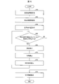
- FIG. 3 is a flowchart illustrating an example of control in the display device 1a according to the present embodiment.
- step S30 the destination information acquisition unit 11 acquires information indicating the destination included in the emergency information from the communication unit 20.
- the display control unit 17 causes the display unit 28 to display emergency information including the destination (“Hama street” in this example) as the second location as character information.
- step S32 the current location information acquisition unit 12 acquires information indicating the current location (“Tokyo” in this example) from the positioning unit 22.
- the reference point position information acquisition unit 13 inputs a reference point position serving as a reference for comparison display, and acquires information indicating the reference point position according to the content detected by the touch sensor unit 26. To do.
- the reference point position information acquisition unit 13 acquires information indicating the reference point position from the reference point position information storage area 32.
- the reference point position information acquisition unit 13 acquires information indicating the arbitrary place name as information indicating the reference point position.
- step S36 the distance calculation unit 14 refers to the information indicating the destination acquired by the destination information acquisition unit 11 in step S30 and the information indicating the current location acquired by the current location information acquisition unit 12 in step S32. And the distance between the destination and the destination.
- the direction calculation unit 15 refers to the information indicating the destination acquired by the destination information acquisition unit 11 in step S30 and the information indicating the current location acquired by the current location information acquisition unit 12 in step S32. Calculate the direction from to the destination.
- the corresponding position calculation unit 16 includes information indicating the reference point position acquired by the reference point position information acquisition unit 13 in step S34, the distance calculated by the distance calculation unit 14 in step S36, and a direction calculation unit in step 38. Referring to the direction calculated by 15, a corresponding position that is separated from the reference point position in the direction from the current location to the destination by the distance between the current location and the destination is calculated.
- step S42 the display control unit 17 causes the display unit 28a to display the corresponding position calculated in step 40 as character information in addition to the emergency information.
- the reference point position as the third place is “Osaka”
- the corresponding position as the fourth place is “Kanazawa Ishikawa”.
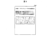
- FIG. 5 shows another display example of the display unit of the display device 1a according to the present embodiment.
- the display unit 28a ′ includes a first map including Tokyo as a first place and Fukushima Hamadori as a second place, and Osaka as a third place. And a second map including Kanazawa as the fourth place are displayed side by side. Further, the display unit 28a 'highlights places corresponding to each of Tokyo, Fukushimahama-dori, Osaka, and Kanazawa on the map.
- the display unit 28a may not display all of the first to fourth places, and may display at least one of the first to fourth places as map information.
- FIG. 6 is a flowchart illustrating an example of control in the display device according to the present embodiment.
- a user residing in Utsunomiya is traveling in Rome.
- Steps S68 to S74 of the present embodiment correspond to steps S36 to S42 shown in FIG. 3 of the first embodiment.
- the destination information acquisition unit 11 acquires a plurality of pieces of information indicating the destination.
- step S60 the destination information acquisition unit 11 acquires information indicating a plurality of destinations included in the emergency information from the communication unit 20.
- the display control unit 17 displays a destination as a second place (in this example, “(1) Trevi Fountain”, “(2) Pantheon”, “ Emergency information including “(3) Titan” and “(4) Roman Forum”) is displayed as text information.
- step S62 the current location information acquisition unit 12 acquires information indicating the current location (“Colosseum” in this example) from the positioning unit 22.
- step S64 the reference point position information acquisition unit 13 inputs a reference point position serving as a reference for comparative display, and the reference point position (in the present example, “JR”) according to the content detected by the touch sensor unit 26. Get Utsunomiya Station)) information.
- step 66 the control unit 10 determines whether or not there is a destination for which the corresponding position is not calculated for a plurality of destinations. If it is determined in step 66 that there is a destination for which the control unit 10 has not calculated the corresponding position (YES), the control unit 10 executes the processes of steps S68 to S72. If it is determined in step 66 that there is no destination for which the control unit 10 has not calculated the corresponding position (NO), the process proceeds to step S74.
- step S74 the display control unit 17 causes the display unit 28 to display the corresponding position calculated in step S72 as character information in addition to the emergency information on the display unit 28b ′ as shown in FIG. 7B.
- the reference point position as the third place is “JR Utsunomiya Station”
- the corresponding position as the fourth place is “(1) Hachimanyama Park”, “(2) Prefectural Office”, “( 3) Sakushin Gakuin "and” (4) Intersection of Odori and Usho Dori ".
- FIG. 8 is a diagram showing an appearance of the display device 1c according to the present embodiment.
- the display device 1c is a television receiver.
- the display device 1b includes a display unit 28c.
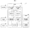
- FIG. 9 is a block diagram illustrating an example of a main configuration of the display device 1c according to the present embodiment.
- the display device 1c includes a control unit 10c, a storage unit 30c, a broadcast receiving unit 38, and a remote control receiving unit 40 in addition to the display unit 28c.
- the storage unit 30 c includes a map information storage area 34 and a current location information storage area 36.
- the current location information storage area 36 stores information indicating the location where the display device 1c is installed.
- the broadcast receiving unit 38 is a tuner and receives a broadcast channel signal.
- the destination information acquisition unit 11c in the present embodiment acquires information indicating the location included in the emergency early warning as information indicating the destination when the broadcast receiving unit 38 receives a signal including the emergency early warning.
- the remote control receiving unit 40 receives a signal corresponding to a user operation from a remote controller operated by the user.
- the user can designate the reference point position by operating the remote controller.
- the reference point position information acquisition unit 13c in the present embodiment acquires information indicating the reference point position via the remote control reception unit 40.
- the reference point position information acquisition unit 13c acquires a plurality of pieces of information indicating the reference point position.
- FIG. 10 is a flowchart illustrating an example of control in the display device 1c according to the present embodiment.
- Step S100 to step S104 and step S108 to step S114 of the present embodiment correspond to step S30 to step S42 shown in FIG. 3 of the first embodiment.
- step 104 when the reference point position information acquisition unit 13c acquires a reference point position as a reference for comparison display, the process proceeds to step 106.
- step 106 the control unit 10c determines whether or not there is a reference point position for which a corresponding position is not calculated for a plurality of reference point positions. If it is determined in step 106 that there is a reference point position for which the control unit 10c has not calculated the corresponding position (YES), the control unit 10c executes steps S108 to S112. If it is determined in step 106 that there is no reference point position for which the control unit 10c has not calculated the corresponding position (NO), the process proceeds to step S104, and the display control unit 17 displays information indicating a plurality of corresponding positions on the display unit. It is displayed as character information in 28c.
- FIG. 11 shows a display example of the display unit 28c of the display device 1c according to the present embodiment.
- Each of a user living in Osaka and a user living in Beijing designates “Osaka” and “Beijing” as reference point positions by operating the remote controller.
- the reference point position information acquisition unit 13c acquires information indicating “Osaka” and information indicating “Beijing” as information indicating the reference point position via the remote control reception unit 40.
- the corresponding position calculation unit 16 calculates a corresponding position having “Osaka” as the reference point position and a corresponding position having “Beijing” as the reference point position. Then, as shown in FIG. 11B, the display unit 28c ′ displays the corresponding position with “Osaka” as the reference point position and the corresponding position with “Beijing” as the reference point position in addition to the emergency information. Display as information.
- the reference point position as the first third place is “Osaka”, and the corresponding position as the fourth place is “Kanazawa Ishikawa”.
- the reference point position as the second third place is “Beijing”, and the corresponding position as the fourth place is “Hebei Chengde”.
- the corresponding positions with the respective residences as reference point positions are displayed as character information, so that each user has a location of a place without a land check Relationships are intuitive and easy to understand.
- the reference point position information acquisition unit 13c acquires information indicating the reference point position.
- the method for acquiring the information indicating the reference point position is as follows. Not limited to this. For example, when the place where the display device is installed is a hotel, a hotel employee may input information indicating the address of the guest into the display device.
- control blocks (particularly the corresponding position calculation unit 16 and the display control unit 17) of the display devices 1a and 1c may be realized by a logic circuit (hardware) formed in an integrated circuit (IC chip) or the like, or a CPU ( It may be realized by software using a Central Processing Unit.
- the display devices 1a and 1c include a CPU that executes instructions of a program that is software for realizing each function, and a ROM (Read (Only Memory) in which the program and various data are recorded so as to be readable by the computer (or CPU). ) Or a storage device (these are referred to as “recording media”), a RAM (Random Access Memory) that expands the program, and the like.
- recording media a “non-temporary tangible medium” such as a tape, a disk, a card, a semiconductor memory, a programmable logic circuit, or the like can be used.
- the program may be supplied to the computer via an arbitrary transmission medium (such as a communication network or a broadcast wave) that can transmit the program.
- an arbitrary transmission medium such as a communication network or a broadcast wave
- one embodiment of the present invention can also be realized in the form of a data signal embedded in a carrier wave, in which the program is embodied by electronic transmission.
- Display devices 1a and 1c according to aspect 1 of the present invention are display devices 1a and 1c including display units 28 and 28c for displaying emergency information, and the distance from a third place serving as a reference point is A fourth location that is the same as the distance between the first location included in the emergency information and the second location that is the current location is displayed as text information.
- the distance between two locations on the map is easy to understand.
- 1a and 1c according to aspect 2 of the present invention are the above-described aspect 1, wherein the direction to the fourth place with respect to the third place is the second place with respect to the first place. It may be the same as the direction to.
- the display units 28 and 28c may display at least one of the first to fourth places as map information.
- both the map and the character information can be visually recognized, so the location is easy to understand.
- the display devices 1a and 1c according to each aspect of the present invention may be realized by a computer.
- the display device is operated by causing the computer to operate as each unit (software element) included in the display devices 1a and 1c.
- a display control program for a display device that realizes the above on a computer and a computer-readable recording medium on which the display control program is recorded fall within the scope of the present invention.
Landscapes
- Engineering & Computer Science (AREA)
- Physics & Mathematics (AREA)
- Theoretical Computer Science (AREA)
- Mathematical Physics (AREA)
- Business, Economics & Management (AREA)
- Educational Administration (AREA)
- Educational Technology (AREA)
- General Physics & Mathematics (AREA)
- Instructional Devices (AREA)
- Navigation (AREA)
Abstract
地図上の複数の場所の間の距離が分かりやすいように地図を表示する。場所情報を含む受信情報を表示する表示部(28,28c)を備えた表示装置(1a,1c)であって、基準点となる第3の場所からの距離が、場所情報を含む受信情報に含まれる第2の場所と現在地である第1の場所との間の距離と同じである第4の場所を文字情報として表示する。
Description
本発明は表示装置、テレビジョン受像機、表示制御プログラム、および記録媒体に関する。
地図情報を表示する画面を2以上の画面に分割し、各々の画面に異なる地図情報を表示する表示装置が従来技術として知られている(例えば特許文献1)。
例えば生活圏外の地域等の土地鑑(土地勘とも表記される)の無い地域の地図上の複数の場所を示されたとしても、各々の場所がどれだけ離れているかが分かりにくい。このように地図上の複数の場所がどれだけ離れているかを分かりやすいように地図を表示する技術が求められている。
本発明の一態様は、地図上の複数の場所の間の距離が分かりやすいように地図を表示することを目的とする。
上記の課題を解決するために、本発明の一態様に係る表示装置は、場所情報を含む受信情報を表示する表示部を備えた表示装置であって、基準点となる第3の場所からの距離が、前記場所情報を含む受信情報に含まれる第1の場所と現在地である第2の場所との間の距離と同じである第4の場所を文字情報として表示する。
本発明の一態様によれば、地図上の2つの場所の間の距離が分かりやすい、という効果を奏する。
〔実施形態1〕
本発明の一実施形態について図1から図5に基づいて説明する。
本発明の一実施形態について図1から図5に基づいて説明する。
図1は、本実施形態に係る表示装置1aの外観を示す図である。本実施形態において、表示装置1aは、スマートフォン、タブレット端末等の携帯情報端末である。表示装置1aは、タッチパネル24を備えている。
図2は、本実施形態に係る表示装置1aの要部構成の一例を示すブロック図である。図2に示すように、表示装置1aは、制御部10、通信部20、測位部22、タッチパネル24、および記憶部30を備える。
通信部20は、インターネット等の通信網と接続し、データ通信を行う。通信部20は、場所情報を含む受信情報を取得する。本実施形態において通信部20は、場所情報を含む受信情報の一例として、緊急情報を取得する。また、通信部20は、地図を示す情報である地図情報を取得する地図情報取得部として機能する。
測位部22は、表示装置1aの現在地を、例えばGPSを利用して測位する。
タッチパネル24は、タッチセンサ部26、および表示部28を含む。
タッチセンサ部26は、ユーザーがタッチした位置を検出するセンサである。
表示部28は、液晶ディスプレイ等の表示デバイスである。表示部28は、通信部20が取得した緊急情報を表示する。
記憶部30は、データ、プログラムの格納領域であり、フラッシュメモリ等から構成される。記憶部30は、基準点位置情報保存領域32、および地図情報保存領域34を含む。
制御部10は、目的地情報取得部11、現在地情報取得部12、基準点位置情報取得部13、距離算出部14、方角算出部15、対応位置算出部16、および表示制御部17として機能する。
目的地情報取得部11は、通信部20が受信した緊急速報に含まれる場所を示す情報を、目的地を示す情報として取得する。
現在地情報取得部12は、測位部22が測位した現在地を示す情報を取得する。
基準点位置情報取得部13は、基準点位置情報保存領域32に格納されている基準点位置を示す情報、またはユーザーが入力し、タッチセンサ部26が検出した基準点位置を示す情報を取得する。
距離算出部14は、目的地情報取得部11が取得した目的地を示す情報、および現在地情報取得部12が取得した現在地を示す情報を参照して、現在地と目的地との距離を算出する。
方角算出部15は、目的地情報取得部11が取得した目的地を示す情報、および現在地情報取得部12が取得した現在地を示す情報を参照して、現在地から目的地に向かう方角を算出する。
対応位置算出部16は、基準点位置情報取得部13が取得した基準点の位置を示す情報、距離算出部14が算出した距離、方角算出部15が算出した方角、および地図情報保存領域34に保存されている地図情報から、基準点位置を参照して、現在地から目的地に向かう方角に、現在地と目的地との距離だけ離れた対応位置を算出する。ただし、算出した対応位置が、海上等の、現在地と目的地との位置関係がかえってわかりにくくなるような不適切な位置であった場合は、現在地と目的地との距離だけ基準点位置から離れた位置を対応位置として再度算出する。
表示制御部17は、表示部28の表示を制御する。表示制御部17は、表示部28に、基準点となる第3の場所からの距離が、緊急情報に含まれる第2の場所としての目的地と現在地である第1の場所との間の距離と同じである第4の場所を文字情報として表示させる。また、表示制御部17は、現在地から目的地に向かう方角と、基準点位置から対応位置に向かう方角とが異なる場合は、現在地と目的地との距離、および現在地から目的地に向かう方角を付随的に表示する。
続いて、図3および図4を参照して、本実施形態に係る表示装置1aにおける制御を説明する。図3は、本実施形態に係る表示装置1aにおける制御の一例を説明するフローチャートである。
ステップS30において、目的地情報取得部11は、通信部20から緊急情報に含まれる目的地を示す情報を取得する。表示制御部17は、図4の(a)に示すように、表示部28に第2の場所としての目的地(本例において「浜通り」)を含む緊急情報を文字情報として表示させる。
ステップS32において、現在地情報取得部12は、測位部22から現在地(本例において「東京」)を示す情報を取得する。
ステップS34において、基準点位置情報取得部13は、比較表示するための基準となる基準点位置を、ユーザーが入力し、タッチセンサ部26が検出した内容に応じて基準点位置を示す情報を取得する。ユーザーが、タッチパネル24において、「いつもの場所」を選択した場合、基準点位置情報取得部13は、基準点位置情報保存領域32から基準点位置を示す情報を取得する。また、ユーザーが、タッチパネル24において、任意の地名を選択した場合、基準点位置情報取得部13は、任意の地名を示す情報を、基準点位置を示す情報として取得する。
ステップS36において、距離算出部14は、ステップS30において目的地情報取得部11が取得した目的地を示す情報、およびステップS32において現在地情報取得部12が取得した現在地を示す情報を参照して、現在地と目的地との距離を算出する。
ステップS38において、方角算出部15は、ステップS30において目的地情報取得部11が取得した目的地を示す情報、およびステップS32において現在地情報取得部12が取得した現在地を示す情報を参照して、現在地から目的地に向かう方角を算出する。
ステップS40において、対応位置算出部16は、ステップS34において基準点位置情報取得部13が取得した基準点位置を示す情報、ステップS36において距離算出部14が算出した距離、およびステップ38において方角算出部15が算出した方角を参照して、基準点位置から、現在地から目的地に向かう方角に、現在地と目的地との距離だけ離れた対応位置を算出する。
ステップS42において、表示制御部17は、図4の(b)に示すように、表示部28aに、緊急情報に加え、ステップ40において算出した対応位置を文字情報として表示させる。本例においては、第3の場所としての基準点位置は「大阪」であり、第4の場所としての対応位置は「石川県金沢」である。
大阪在住のユーザーにとって東京およびその周辺が土地鑑のない場所であった場合、ユーザーは東京から福島浜通りがどのくらい離れているのかがすぐに分からない。本実施形態は、通常生活している生活圏に土地鑑のない場所を置き換えて表示するので、土地鑑のない場所の位置関係が直感的に分かりやすくなる。
図5に、本実施形態に係る表示装置1aの表示部の他の表示例を示す。表示部28a’は、図5に示すように、文字情報に加え、第1の場所としての東京と第2の場所としての福島浜通りを含む第1の地図と、第3の場所としての大阪と第4の場所としての金沢とを含む第2の地図を並べて表示する。また、表示部28a’は、地図上の、東京、福島浜通り、大阪、および金沢の各々に該当する場所を強調表示する。なお、表示部28aは、第1から第4の場所の全てを表示しなくてもよく、第1から第4の場所の少なくとも何れかを地図情報として表示してもよい。
〔実施形態2〕
本発明の他の実施形態について、図6~図7に基づいて説明すれば、以下のとおりである。なお、本実施例に係る表示装置は、実施形態1にて説明した部材と同じ機能を有する部材を備えているので、部材については、その説明を省略する。
本発明の他の実施形態について、図6~図7に基づいて説明すれば、以下のとおりである。なお、本実施例に係る表示装置は、実施形態1にて説明した部材と同じ機能を有する部材を備えているので、部材については、その説明を省略する。
図6は、本実施形態に係る表示装置における制御の一例を説明するフローチャートである。例えば宇都宮在住のユーザーが、ローマを旅行しているとする。
本実施形態のステップS68~ステップS74は、実施形態1の図3に示すステップS36~ステップS42に対応する。
本実施形態においては、目的地情報取得部11が、目的地を示す情報を複数取得する。
ステップS60において、目的地情報取得部11は、通信部20から緊急情報に含まれる複数の目的地を示す情報を取得する。表示制御部17は、図7の(a)に示すように、表示部28bに第2の場所としての目的地(本例において「(1)トレヴィの泉」、「(2)パンテオン」、「(3)ヴァチカン」、および「(4)フォロ・ロマーノ」)を含む緊急情報を文字情報として表示させる。
ステップS62において、現在地情報取得部12は、測位部22から現在地(本例において「コロッセオ」)を示す情報を取得する。
ステップS64において、基準点位置情報取得部13は、比較表示するための基準となる基準点位置をユーザーが入力し、タッチセンサ部26が検出した内容に応じて基準点位置(本例において「JR宇都宮駅」)を示す情報を取得する。
ステップ66において、制御部10は、複数の目的地について、対応位置が算出されていない目的地が存在するか否かを判定する。ステップ66において制御部10が対応位置を算出していない目的地が存在すると判定する(YES)と、制御部10は、ステップS68~ステップS72の処理を実行する。ステップ66において制御部10が対応位置を算出していない目的地が存在しないと判定する(NO)と、ステップS74に移行する。
ステップS74において、表示制御部17は、表示部28に、図7の(b)に示すように、表示部28b’に、緊急情報に加え、ステップS72において算出した対応位置を文字情報として表示させる。本例においては、第3の場所としての基準点位置は「JR宇都宮駅」であり、第4の場所としての対応位置は「(1)八幡山公園」、「(2)県庁」、「(3)作新学院」、および「(4)大通りと宇商通りの交差点」である。
宇都宮在住のユーザーにとってローマが土地鑑のない場所であった場合、「コロッセオ」から「(1)トレヴィの泉」、「(2)パンテオン」、「(3)ヴァチカン」、および「(4)フォロ・ロマーノ」の各々がどのくらい離れているのかがすぐに分からない。本実施形態によれば、通常生活している生活圏に土地鑑のない複数の場所を置き換えて表示するので、土地鑑のない複数の場所の位置関係が直感的に分かりやすくなる。
〔実施形態3〕
本発明の他の実施形態について、図8~図11に基づいて説明すれば、以下のとおりである。なお、説明の便宜上、前記実施形態にて説明した部材と同じ機能を有する部材については、同じ符号を付記し、その説明を省略する。
本発明の他の実施形態について、図8~図11に基づいて説明すれば、以下のとおりである。なお、説明の便宜上、前記実施形態にて説明した部材と同じ機能を有する部材については、同じ符号を付記し、その説明を省略する。
図8は、本実施形態に係る表示装置1cの外観を示す図である。本実施形態において、表示装置1cは、テレビジョン受像機である。表示装置1bは、表示部28cを備えている。
図9は、本実施形態に係る表示装置1cの要部構成の一例を示すブロック図である。図9に示すように、表示装置1cは、表示部28cの他に、制御部10c、記憶部30c、放送受信部38、およびリモコン受信部40を備える。
記憶部30cは、地図情報保存領域34、および現在地情報保存領域36を含む。
現在地情報保存領域36は、表示装置1cが設置されている場所を示す情報を格納している。
放送受信部38は、チューナーであり、放送チャンネル信号を受信する。
本実施形態における目的地情報取得部11cは、放送受信部38が緊急速報を含む信号を受信した場合、緊急速報に含まれる場所を示す情報を、目的地を示す情報として取得する。
リモコン受信部40は、ユーザーが操作するリモートコントローラからユーザーの操作に応じた信号を受信する。ユーザーは、リモートコントローラの操作により、基準点位置を指定することができる。
本実施形態における基準点位置情報取得部13cは、リモコン受信部40を介して、基準点位置を示す情報を取得する。複数のユーザーが各々の基準点位置を指定した場合、基準点位置情報取得部13cは、基準点位置を示す情報を複数取得する。
図10は、本実施形態に係る表示装置1cにおける制御の一例を説明するフローチャートである。
本実施形態のステップS100~ステップS104、およびステップS108~ステップS114は、実施形態1の図3に示すステップS30~ステップS42に対応する。
ステップ104において基準点位置情報取得部13cが比較表示するための基準となる基準点位置を取得すると、ステップ106に移行する。
ステップ106において、制御部10cは、複数の基準点位置について、対応位置が算出されていない基準点位置が存在するか否かを判定する。ステップ106において制御部10cが対応位置を算出していない基準点位置が存在すると判定する(YES)と、制御部10cはステップS108~ステップS112の処理を実行する。ステップ106において制御部10cが対応位置を算出していない基準点位置が存在しないと判定する(NO)と、ステップS104に移行し、表示制御部17は複数の対応位置を示す情報を、表示部28cに文字情報として表示させる。
図11に、本実施形態に係る表示装置1cの表示部28cの表示例を示す。例えば、東京において、大阪に住むユーザーと、北京に住むユーザーとが表示を視聴している表示装置1cが、図11の(a)に示すように「浜通りで地震発生」との緊急速報を受信したとする。大阪に住むユーザーと北京に住むユーザーの各々は、リモートコントローラを操作して、「大阪」、「北京」を基準点位置として指定する。これに応じて、基準点位置情報取得部13cは、リモコン受信部40を介して、「大阪」を示す情報、および「北京」を示す情報を、基準点位置を示す情報として取得する。対応位置算出部16は、「大阪」を基準点位置とする対応位置、および「北京」を基準点位置とする対応位置の各々を算出する。そして、表示部28c’は、図11の(b)に示すように、緊急情報に加え、「大阪」を基準点位置とする対応位置、および「北京」を基準点位置とする対応位置を文字情報として表示させる。本例においては、1つめの第3の場所としての基準点位置は「大阪」であり、第4の場所としての対応位置は「石川県金沢」である。また、2つめの第3の場所としての基準点位置は「北京」であり、第4の場所としての対応位置は「河北省承徳」である。本実施形態によれば、居住地が異なるユーザーが複数人いる場合、各々の居住地を基準点位置とする対応位置を文字情報として各々表示するので、各々のユーザーは土地鑑のない場所の位置関係が直感的に分かりやすくなる。
なお、本実施形態においては、ユーザーがリモートコントローラを操作することにより、基準点位置情報取得部13cは、基準点位置を示す情報を取得しているが、基準点位置を示す情報の取得方法はこれに限らない。例えば表示装置が設置されている場所がホテルである場合、ホテルの従業員が、宿泊者の住所を示す情報を、表示装置に入力してもよい。
〔ソフトウェアによる実現例〕
表示装置1a,1cの制御ブロック(特に対応位置算出部16および表示制御部17)は、集積回路(ICチップ)等に形成された論理回路(ハードウェア)によって実現してもよいし、CPU(Central Processing Unit)を用いてソフトウェアによって実現してもよい。
表示装置1a,1cの制御ブロック(特に対応位置算出部16および表示制御部17)は、集積回路(ICチップ)等に形成された論理回路(ハードウェア)によって実現してもよいし、CPU(Central Processing Unit)を用いてソフトウェアによって実現してもよい。
後者の場合、表示装置1a,1cは、各機能を実現するソフトウェアであるプログラムの命令を実行するCPU、上記プログラムおよび各種データがコンピュータ(またはCPU)で読み取り可能に記録されたROM(Read Only Memory)または記憶装置(これらを「記録媒体」と称する)、上記プログラムを展開するRAM(Random Access Memory)などを備えている。そして、コンピュータ(またはCPU)が上記プログラムを上記記録媒体から読み取って実行することにより、本発明の目的が達成される。上記記録媒体としては、「一時的でない有形の媒体」、例えば、テープ、ディスク、カード、半導体メモリ、プログラマブルな論理回路などを用いることができる。また、上記プログラムは、該プログラムを伝送可能な任意の伝送媒体(通信ネットワークや放送波等)を介して上記コンピュータに供給されてもよい。なお、本発明の一態様は、上記プログラムが電子的な伝送によって具現化された、搬送波に埋め込まれたデータ信号の形態でも実現され得る。
〔まとめ〕
本発明の態様1に係る表示装置1a,1cは、緊急情報を表示する表示部28,28cを備えた表示装置1a,1cであって、基準点となる第3の場所からの距離が、前記緊急情報に含まれる第1の場所と現在地である第2の場所との間の距離と同じである第4の場所を文字情報として表示する。
本発明の態様1に係る表示装置1a,1cは、緊急情報を表示する表示部28,28cを備えた表示装置1a,1cであって、基準点となる第3の場所からの距離が、前記緊急情報に含まれる第1の場所と現在地である第2の場所との間の距離と同じである第4の場所を文字情報として表示する。
上記の構成によれば、地図上の2つの場所の間の距離が分かりやすい。
本発明の態様2に係る1a,1cは、上記態様1において、前記第3の場所を基準とした前記第4の場所への方角は、前記第1の場所を基準とした前記第2の場所への方角と同じであってもよい。
上記の構成によれば、地図上の2つの場所の位置関係が分かりやすい。
本発明の態様3に係る1a,1cは、上記態様1または2において、前記表示部28,28cは、前記第1から第4の場所の少なくとも何れかを地図情報として表示してもよい。
上記の構成によれば、地図と文字情報との両方を視認できるので、場所がわかりやすい。
本発明の各態様に係る表示装置1a,1cは、コンピュータによって実現してもよく、この場合には、コンピュータを上記表示装置1a,1cが備える各部(ソフトウェア要素)として動作させることにより上記表示装置をコンピュータにて実現させる表示装置の表示制御プログラム、およびそれを記録したコンピュータ読み取り可能な記録媒体も、本発明の範疇に入る。
本発明は上述した各実施形態に限定されるものではなく、請求項に示した範囲で種々の変更が可能であり、異なる実施形態にそれぞれ開示された技術的手段を適宜組み合わせて得られる実施形態についても本発明の技術的範囲に含まれる。さらに、各実施形態にそれぞれ開示された技術的手段を組み合わせることにより、新しい技術的特徴を形成することができる。
1a,1c 表示装置
16 対応位置算出部
17 表示制御部
28,28c 表示部
16 対応位置算出部
17 表示制御部
28,28c 表示部
Claims (6)
- 場所情報を含む受信情報を表示する表示部を備えた表示装置であって、
基準点となる第3の場所からの距離が、前記場所情報を含む受信情報に含まれる第2の場所と現在地である第1の場所との間の距離と同じである第4の場所を文字情報として表示する
ことを特徴とする表示装置。 - 前記第3の場所を基準とした前記第4の場所への方角は、前記第1の場所を基準とした前記第2の場所への方角と同じである
ことを特徴とする請求項1に記載の表示装置。 - 前記表示部は、前記第1から第4の場所の少なくとも何れかを地図情報として表示することを特徴とする請求項1または2に記載の表示装置。
- 請求項1~3の何れか1項に記載の表示装置を備えることを特徴とするテレビジョン受像機。
- 請求項1に記載の表示装置としてコンピュータを機能させるための表示制御プログラムであって、上記表示部としてコンピュータを機能させるための表示制御プログラム。
- 請求項5に記載の表示制御プログラムを記録したコンピュータ読み取り可能な記録媒体。
Applications Claiming Priority (2)
| Application Number | Priority Date | Filing Date | Title |
|---|---|---|---|
| JP2017022033A JP6453368B2 (ja) | 2017-02-09 | 2017-02-09 | 表示装置、テレビジョン受像機、表示制御プログラム、および記録媒体 |
| JP2017-022033 | 2017-02-09 |
Publications (1)
| Publication Number | Publication Date |
|---|---|
| WO2018147198A1 true WO2018147198A1 (ja) | 2018-08-16 |
Family
ID=63108200
Family Applications (1)
| Application Number | Title | Priority Date | Filing Date |
|---|---|---|---|
| PCT/JP2018/003669 Ceased WO2018147198A1 (ja) | 2017-02-09 | 2018-02-02 | 表示装置、テレビジョン受像機、表示制御プログラム、および記録媒体 |
Country Status (2)
| Country | Link |
|---|---|
| JP (1) | JP6453368B2 (ja) |
| WO (1) | WO2018147198A1 (ja) |
Citations (4)
| Publication number | Priority date | Publication date | Assignee | Title |
|---|---|---|---|---|
| US20040243306A1 (en) * | 2003-06-02 | 2004-12-02 | Han Maung W. | Display method and apparatus for navigation system |
| JP2013137247A (ja) * | 2011-12-28 | 2013-07-11 | Panasonic Corp | ナビゲーション装置 |
| WO2014020994A1 (ja) * | 2012-07-31 | 2014-02-06 | 古野電気株式会社 | 気象情報表示システム、ヒューマンナビゲーション装置、及び気象情報表示方法 |
| JP2015137856A (ja) * | 2014-01-20 | 2015-07-30 | ヤフー株式会社 | 行き先候補表示システム、行き先候補表示方法及びプログラム |
-
2017
- 2017-02-09 JP JP2017022033A patent/JP6453368B2/ja active Active
-
2018
- 2018-02-02 WO PCT/JP2018/003669 patent/WO2018147198A1/ja not_active Ceased
Patent Citations (4)
| Publication number | Priority date | Publication date | Assignee | Title |
|---|---|---|---|---|
| US20040243306A1 (en) * | 2003-06-02 | 2004-12-02 | Han Maung W. | Display method and apparatus for navigation system |
| JP2013137247A (ja) * | 2011-12-28 | 2013-07-11 | Panasonic Corp | ナビゲーション装置 |
| WO2014020994A1 (ja) * | 2012-07-31 | 2014-02-06 | 古野電気株式会社 | 気象情報表示システム、ヒューマンナビゲーション装置、及び気象情報表示方法 |
| JP2015137856A (ja) * | 2014-01-20 | 2015-07-30 | ヤフー株式会社 | 行き先候補表示システム、行き先候補表示方法及びプログラム |
Also Published As
| Publication number | Publication date |
|---|---|
| JP2018128592A (ja) | 2018-08-16 |
| JP6453368B2 (ja) | 2019-01-16 |
Similar Documents
| Publication | Publication Date | Title |
|---|---|---|
| US10121449B2 (en) | Method and apparatus for screen sharing | |
| KR102276847B1 (ko) | 가상 오브젝트 제공 방법 및 그 전자 장치 | |
| KR102160975B1 (ko) | 전자장치로 위치 기반 서비스를 제공하기 위한 방법 및 시스템 | |
| US10066948B2 (en) | Method and apparatus for generating map-based snippets | |
| KR20160060386A (ko) | 윈도우의 크기를 변경하는 디바이스 및 그 제어 방법 | |
| US8604977B2 (en) | Real-time markup of maps with user-generated content | |
| US20150002539A1 (en) | Methods and apparatuses for displaying perspective street view map | |
| KR20160071785A (ko) | 음향 출력을 제어하는 디바이스 및 그 방법 | |
| KR20180042551A (ko) | 전자 장치 및 그의 제어 방법 | |
| KR20160118000A (ko) | 위젯 제공 시스템 및 방법 | |
| KR20190022429A (ko) | 데이터 표시 방법, 장치, 단말 및 저장 매체 | |
| KR101615504B1 (ko) | 휴대용 단말기에서 컨텐츠를 저장하고 검색하는 방법 및 장치 | |
| US20140195980A1 (en) | Display apparatus and method for providing user interface thereof | |
| JP2018097683A (ja) | 表示制御プログラム、表示制御方法および表示制御装置 | |
| WO2014089319A2 (en) | Predictively presenting search capabilities | |
| JP2017163195A (ja) | 画像処理システム、プログラム、画像処理方法 | |
| US12424105B2 (en) | Information processing method, information processing system, and control program | |
| KR102013728B1 (ko) | 재난 상황 정보 공유 장치 및 방법 | |
| JP2018072980A (ja) | 情報提供システム、情報提供システムの制御方法、およびプログラム | |
| US20170205899A1 (en) | Display control device, display control method, and program | |
| JP6453368B2 (ja) | 表示装置、テレビジョン受像機、表示制御プログラム、および記録媒体 | |
| US20150133165A1 (en) | Method for processing data and electronic device thereof | |
| JP6563432B2 (ja) | 表示装置、テレビジョン受像機、表示制御プログラム、および記録媒体 | |
| CN104967907A (zh) | 视频播放定位的方法和系统 | |
| JP2018097694A (ja) | 送信制御プログラム、送信制御方法および情報処理装置 |
Legal Events
| Date | Code | Title | Description |
|---|---|---|---|
| 121 | Ep: the epo has been informed by wipo that ep was designated in this application |
Ref document number: 18751694 Country of ref document: EP Kind code of ref document: A1 |
|
| NENP | Non-entry into the national phase |
Ref country code: DE |
|
| 122 | Ep: pct application non-entry in european phase |
Ref document number: 18751694 Country of ref document: EP Kind code of ref document: A1 |