WO2018143201A1 - 車両用ミラー装置 - Google Patents
車両用ミラー装置 Download PDFInfo
- Publication number
- WO2018143201A1 WO2018143201A1 PCT/JP2018/002984 JP2018002984W WO2018143201A1 WO 2018143201 A1 WO2018143201 A1 WO 2018143201A1 JP 2018002984 W JP2018002984 W JP 2018002984W WO 2018143201 A1 WO2018143201 A1 WO 2018143201A1
- Authority
- WO
- WIPO (PCT)
- Prior art keywords
- vehicle
- mirror
- monitor
- operated
- rear side
- Prior art date
- Legal status (The legal status is an assumption and is not a legal conclusion. Google has not performed a legal analysis and makes no representation as to the accuracy of the status listed.)
- Ceased
Links
Images


Classifications
-
- B—PERFORMING OPERATIONS; TRANSPORTING
- B60—VEHICLES IN GENERAL
- B60R—VEHICLES, VEHICLE FITTINGS, OR VEHICLE PARTS, NOT OTHERWISE PROVIDED FOR
- B60R1/00—Optical viewing arrangements; Real-time viewing arrangements for drivers or passengers using optical image capturing systems, e.g. cameras or video systems specially adapted for use in or on vehicles
- B60R1/20—Real-time viewing arrangements for drivers or passengers using optical image capturing systems, e.g. cameras or video systems specially adapted for use in or on vehicles
- B60R1/22—Real-time viewing arrangements for drivers or passengers using optical image capturing systems, e.g. cameras or video systems specially adapted for use in or on vehicles for viewing an area outside the vehicle, e.g. the exterior of the vehicle
- B60R1/23—Real-time viewing arrangements for drivers or passengers using optical image capturing systems, e.g. cameras or video systems specially adapted for use in or on vehicles for viewing an area outside the vehicle, e.g. the exterior of the vehicle with a predetermined field of view
- B60R1/26—Real-time viewing arrangements for drivers or passengers using optical image capturing systems, e.g. cameras or video systems specially adapted for use in or on vehicles for viewing an area outside the vehicle, e.g. the exterior of the vehicle with a predetermined field of view to the rear of the vehicle
-
- B—PERFORMING OPERATIONS; TRANSPORTING
- B60—VEHICLES IN GENERAL
- B60R—VEHICLES, VEHICLE FITTINGS, OR VEHICLE PARTS, NOT OTHERWISE PROVIDED FOR
- B60R1/00—Optical viewing arrangements; Real-time viewing arrangements for drivers or passengers using optical image capturing systems, e.g. cameras or video systems specially adapted for use in or on vehicles
- B60R1/02—Rear-view mirror arrangements
- B60R1/04—Rear-view mirror arrangements mounted inside vehicle
-
- B—PERFORMING OPERATIONS; TRANSPORTING
- B60—VEHICLES IN GENERAL
- B60R—VEHICLES, VEHICLE FITTINGS, OR VEHICLE PARTS, NOT OTHERWISE PROVIDED FOR
- B60R1/00—Optical viewing arrangements; Real-time viewing arrangements for drivers or passengers using optical image capturing systems, e.g. cameras or video systems specially adapted for use in or on vehicles
- B60R1/12—Mirror assemblies combined with other articles, e.g. clocks
-
- H—ELECTRICITY
- H04—ELECTRIC COMMUNICATION TECHNIQUE
- H04N—PICTORIAL COMMUNICATION, e.g. TELEVISION
- H04N7/00—Television systems
- H04N7/18—Closed-circuit television [CCTV] systems, i.e. systems in which the video signal is not broadcast
Definitions
- the present invention relates to a vehicle mirror device in which an image is displayed on the front side of a mirror by operating display means.
- the operation lever member is operated to change the direction of the mirror surface of the half mirror. Further, the liquid crystal display device is activated to display an image on the front side of the half mirror.
- the operation lever member is operated to the rear side of the vehicle, the direction of the mirror surface of the half mirror is changed to the upper side, and the liquid crystal display device is operated. Further, the operation lever member is operated to the front side of the vehicle, the direction of the mirror surface of the half mirror is changed to the lower side, and the operation of the liquid crystal display device is released.
- the present invention has been made in view of the above facts, and an object of the present invention is to obtain a vehicle mirror device that can separately change the mirror direction of the mirror and at least one of the operation and deactivation of the display means.
- a vehicle mirror device includes a mirror provided in a vehicle interior, display means that is operated to display an image on the front side of the mirror, and a mirror surface direction of the mirror that is operated on the rear side of the vehicle. Is changed to the upper side, the change unit is operated to the front side of the vehicle and the mirror surface direction of the mirror is changed to the lower side, and is arranged on the change unit, and is operated on the vehicle front side of the change unit to display the display And an actuating means provided with at least one of an actuating part for actuating the means and a releasing part operated on the vehicle rear side of the changing part to release the action of the display means.
- a mirror device for a vehicle includes a mirror provided in a vehicle interior, display means that is operated to display an image on the front side of the mirror, a container that houses the mirror, and a vehicle rear side.
- the mirror surface direction of the mirror is operated to be changed to the upper side
- the change unit is operated to the front side of the vehicle and the mirror surface direction of the mirror is changed to the lower side
- the outer peripheral portion of the container is disposed.
- Actuating means provided with at least one of an operating part operated on the vehicle rear side of the changing part to operate the display means and a releasing part operated on the vehicle front side of the changing part to release the operation of the displaying means. And comprising.
- the vehicle mirror device is the vehicle mirror device according to the first aspect or the second aspect of the present invention, wherein the change unit is operated to activate the display means or to activate the display means. Canceled.
- a mirror is provided in the passenger compartment, and the display means is operated to display an image on the front side of the mirror.
- the changing unit is operated to the rear side of the vehicle, the mirror surface direction of the mirror is changed to the upper side, and the changing unit is operated to the front side of the vehicle, and the mirror surface direction of the mirror is changed to the lower side.
- an operating means is disposed in the changing portion, and at least one of the operating portion and the releasing portion is provided in the operating means, the operating portion is operated on the vehicle front side of the changing portion, the display means is operated, and the releasing portion Is operated on the vehicle rear side of the changing portion, and the operation of the display means is released.
- a mirror is provided in the passenger compartment, and the display means is operated to display an image on the front side of the mirror.
- a container accommodates a mirror.
- the changing unit is operated to the rear side of the vehicle, the mirror surface direction of the mirror is changed to the upper side, and the changing unit is operated to the front side of the vehicle, and the mirror surface direction of the mirror is changed to the lower side.
- the operating means is disposed on the outer peripheral portion of the container, and the operating means is provided with at least one of the operating part and the releasing part, and the operating part is operated on the vehicle rear side of the changing part to operate the display means. Then, the release unit is operated on the vehicle front side of the change unit, and the operation of the display unit is released.
- the changing unit is operated, and the display unit is operated or the display unit is deactivated. Therefore, the operation of the display unit or the operation release of the display unit can be performed by operating the changing unit.
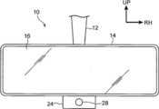
- FIG. 1A shows a vehicle inner mirror device 10 as a vehicle mirror device according to the first embodiment of the present invention in a side view seen from the right side of the vehicle
- FIG. 1B shows a vehicle inner mirror.
- the apparatus 10 is shown in the front view seen from the vehicle rear side.
- the front side of the vehicle is indicated by an arrow FR
- the right side of the vehicle is indicated by an arrow RH
- the upper side is indicated by an arrow UP.
- the inner mirror device 10 for a vehicle according to the present embodiment is installed in the vehicle interior of the vehicle.
- the vehicle inner mirror device 10 includes a substantially columnar stay 12.
- the upper end portion of the stay 12 is attached to the vehicle left-right direction central portion of the front end portion of the upper wall of the vehicle interior, and thereby the vehicle inner mirror device 10 is installed in the vehicle interior.
- a substantially rectangular parallelepiped box-shaped housing 14 as a container is supported at the lower end of the stay 12 at the front side of the vehicle and in the center in the left-right direction of the vehicle.
- the housing 14 is a vehicle centered on the lower end of the stay 12. It can be rotated in the front-rear direction, the vehicle left-right direction, and the vertical direction. Moreover, the inside of the housing 14 is opened to the vehicle rear side.
- a rectangular plate-shaped half mirror 16 as a mirror is fixed (accommodated) to the vehicle rear side end in the housing 14, and the half mirror 16 closes the opening of the housing 14.
- the mirror surface (light reflecting surface) of the half mirror 16 is directed to the vehicle rear side, and the half mirror 16 can reflect light from the vehicle rear side (front side) to the vehicle rear side by the mirror surface. Light from the front side (back side) can be transmitted to the rear side of the vehicle.
- the following monitor 18 is not actuated, light does not arrive at the half mirror 16 from the front side of the vehicle, so that a vehicle occupant (for example, a driver) can see the vehicle rear side (vehicle image) by the reflected light (mirror image) from the mirror surface of the half mirror 16.
- the rear part of the room, the rear of the vehicle, the left diagonal rear and the right diagonal rear) are made visible.
- a rectangular plate-like monitor 18 (liquid crystal display device) as a display means is fixed (accommodated) at the vehicle rear side end portion in the housing 14 on the vehicle front side of the half mirror 16.
- the display screen is directed to the rear side of the vehicle in a state of being arranged parallel to the vertical direction.
- the monitor 18 is actuated so that an image can be displayed on the screen.
- the image arrives at the half mirror 16 from the front side of the vehicle.
- the image can be visually recognized by the transmitted light of the half mirror 16.
- a control device 20 is electrically connected to the monitor 18, and a camera 22 as an imaging unit is electrically connected to the control device 20.
- the camera 22 is installed outside the rear part of the vehicle, and the camera 22 is operated under the control of the control device 20 to image the rear side of the vehicle (the rear side of the vehicle, the diagonally left rear side, and the diagonally right rear side).
- the monitor 18 is operated under the control of the control device 20, whereby the image captured by the camera 22 is displayed on the screen of the monitor 18, and the occupant is transmitted by the transmitted light of the half mirror 16 (display image of the monitor 18).
- the rear side of the vehicle is visible.
- a rectangular plate-shaped operation lever 24 as a changing portion is fixed to the center of the lower surface of the housing 14 in the left-right direction of the vehicle.
- the operation lever 24 protrudes downward, and the rear side of the vehicle and It can be moved to the front of the vehicle.
- the housing 14 including the half mirror 16 and the monitor 18
- the housing 14 is rotated to the vehicle rear side together with the operation lever 24.
- the orientation of the opening of the housing 14, the mirror surface of the half mirror 16, and the screen of the monitor 18 are changed to the upper side.
- the housing 14 (including the half mirror 16 and the monitor 18) is rotated together with the operation lever 24 to the front side of the vehicle.
- the opening of the housing 14, the mirror surface of the half mirror 16, and the orientation of the screen of the monitor 18 are changed to the lower side.
- An ON switch 26 is provided on the vehicle front side surface of the operation lever 24 as an operating part constituting an operating means, and the ON switch 26 can be pressed to the vehicle rear side by a passenger's finger (for example, index finger). ing.
- the ON switch 26 is electrically connected to the control device 20, and the monitor 18 is operated by the control of the control device 20 when the ON switch 26 is pressed.
- An OFF switch 28 serving as a release portion constituting the operating means is provided on the rear side surface of the operation lever 24.
- the OFF switch 28 can be pressed to the front side of the vehicle by a passenger's finger (for example, thumb). Yes.
- the OFF switch 28 is electrically connected to the control device 20, and the operation of the monitor 18 is released by the control of the control device 20 when the OFF switch 28 is pressed.
- the monitor 18 when the monitor 18 is not operated, the occupant can visually recognize the rear side of the vehicle by reflected light from the mirror surface of the half mirror 16.
- an image captured by the camera 22 is displayed on the screen of the monitor 18 so that the occupant can visually recognize the rear side of the vehicle by the transmitted light of the half mirror 16.
- the housing 14 is rotated to the rear side of the vehicle, and the opening of the housing 14, the mirror surface of the half mirror 16, and the monitor The orientation of the 18 screen is changed to the upper side.
- the operation lever 24 is moved to the front side of the vehicle by the passenger's fingers (for example, thumb)
- the housing 14 is rotated to the front side of the vehicle, the opening of the housing 14, the mirror surface of the half mirror 16, and the screen of the monitor 18 The direction of is changed to the lower side.
- the monitor 18 is activated and the occupant is driven by the transmitted light of the half mirror 16.
- the rear side is made visible.
- the OFF switch 28 on the rear side surface of the operation lever 24 is pressed to the front side of the vehicle by the occupant's fingers (for example, thumb), the operation of the monitor 18 is released, and the occupant is reflected by the mirror surface of the half mirror 16.
- the rear side of the vehicle is made visible by light.
- the opening of the housing 14, the mirror surface of the half mirror 16 and the change of the screen orientation of the monitor 18 and the operation and release of the monitor 18 can be performed separately, and the opening of the housing 14, the mirror surface of the half mirror 16 and The monitor 18 can be activated and deactivated without changing the orientation of the screen of the monitor 18, and the opening of the housing 14, the mirror surface of the half mirror 16, and the monitor can be activated without deactivating and deactivating the monitor 18.
- the orientation of the 18 screens can be changed. Thereby, for example, when the vehicle is stopped, the operation of the monitor 18 is canceled, so that the occupant can visually recognize the rear part of the passenger compartment (especially the rear seat (for example, the baby seat child)) by the reflected light from the mirror surface of the half mirror 16.
- the occupant can transmit the light transmitted through the half mirror 16 without changing the orientation of the opening of the housing 14, the mirror surface of the half mirror 16, and the screen of the monitor 18.
- the rear side of the vehicle can be made visible by the display image of the monitor 18).
- the monitor 18 can be operated by pressing the ON switch 26 to the rear side of the vehicle with the occupant's finger (for example, forefinger), and at the same time, the operating lever 24 is moved to the rear side of the vehicle to open the housing 14.
- the direction of the mirror surface of the half mirror 16 and the screen of the monitor 18 can be changed to the upper side. Therefore, the operation for operating the monitor 18 and the operation for changing the opening of the housing 14, the mirror surface of the half mirror 16, and the orientation of the screen of the monitor 18 to the upper side can be performed in one operation.
- the operation of the monitor 18 can be released by pressing the OFF switch 28 to the front side of the vehicle by the occupant's fingers (for example, thumb), and at the same time, the operating lever 24 is moved to the front side of the vehicle to open the housing 14 and the half mirror.
- the direction of the 16 mirror surfaces and the screen of the monitor 18 can be changed to the lower side. Therefore, the operation for releasing the operation of the monitor 18 and the operation for changing the orientation of the opening of the housing 14, the mirror surface of the half mirror 16, and the screen of the monitor 18 to the lower side can be performed in one operation.
- the ON switch 26 is provided between the vehicle rear side of the stay 12 and the housing 14. Thereby, the operation lever 24 is moved to the rear side of the vehicle by the occupant's finger (for example, index finger), and the housing 14 is rotated to the rear side of the vehicle. 14 and the monitor 18 is activated. For this reason, the monitor 18 can be operated by moving the operation lever 24.
- the OFF switch 28 is provided between the vehicle front side of the stay 12 and the housing 14.
- the operation lever 24 is moved to the front side of the vehicle by the occupant's fingers (for example, thumb), and the housing 14 is rotated to the front side of the vehicle, whereby the OFF switch 28 is moved between the front side of the stay 12 and the housing 14.
- the operation of the monitor 18 is released by pressing between them. For this reason, the operation of the monitor 18 can be canceled by the movement operation of the operation lever 24.
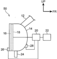
- FIG. 2A shows a vehicle inner mirror device 50 as a vehicle mirror device according to a second embodiment of the present invention in a side view as seen from the right side of the vehicle, and FIG. 2B shows a vehicle inner mirror.
- the apparatus 50 is shown in the front view seen from the vehicle rear side.
- the vehicle inner mirror device 50 according to the present embodiment has substantially the same configuration as the first embodiment, but differs in the following points.
- an ON switch 26 is provided at the vehicle rear side and lower end outer periphery of the housing 14 at the vehicle lateral center.
- the ON switch 26 is disposed on the rear side and the upper side of the operation lever 24, and can be pressed to the front side of the vehicle by the occupant's fingers (for example, thumb).
- An OFF switch 28 is provided on the outer periphery of the end portion of the housing 14 on the vehicle front side and the lower side, in the vehicle left-right central portion, and the OFF switch 28 is disposed on the vehicle front side and the upper side of the operation lever 24.
- a pressing operation can be performed on the rear side of the vehicle by a passenger's finger (for example, an index finger).
- the housing 14 is rotated to the rear side of the vehicle, and the opening of the housing 14, the mirror surface of the half mirror 16, and the monitor The orientation of the 18 screen is changed to the upper side.
- the operation lever 24 is moved to the front side of the vehicle by the passenger's fingers (for example, thumb)
- the housing 14 is rotated to the front side of the vehicle, the opening of the housing 14, the mirror surface of the half mirror 16, and the screen of the monitor 18 The direction of is changed to the lower side.
- the ON switch 26 on the rear side and the lower side of the housing 14 is pressed to the front side of the vehicle by the occupant's fingers (for example, thumb), so that the monitor 18 is activated and the occupant is transmitted by the transmitted light of the half mirror 16.
- the rear side of the vehicle is made visible.
- the OFF switch 28 on the front side and the lower side of the housing 14 is pressed to the rear side of the vehicle by the occupant's finger (for example, the index finger)
- the operation of the monitor 18 is released, and the occupant can mirror the mirror surface of the half mirror 16.
- the rear side of the vehicle can be visually recognized by the reflected light.
- the opening of the housing 14, the mirror surface of the half mirror 16 and the change of the screen orientation of the monitor 18 and the operation and release of the monitor 18 can be performed separately, and the opening of the housing 14, the mirror surface of the half mirror 16 and The monitor 18 can be activated and deactivated without changing the orientation of the screen of the monitor 18, and the opening of the housing 14, the mirror surface of the half mirror 16, and the monitor can be activated without deactivating and deactivating the monitor 18.
- the orientation of the 18 screens can be changed. Thereby, for example, when the vehicle is stopped, the operation of the monitor 18 is canceled, so that the occupant can visually recognize the rear part of the passenger compartment (especially the rear seat (for example, the baby seat child)) by the reflected light from the mirror surface of the half mirror 16.
- the occupant can transmit the light transmitted through the half mirror 16 without changing the orientation of the opening of the housing 14, the mirror surface of the half mirror 16, and the screen of the monitor 18.
- the rear side of the vehicle can be made visible by the display image of the monitor 18).
- the operation lever 24 is moved to the rear side of the vehicle by the occupant's finger (for example, forefinger), and the orientation of the opening of the housing 14, the mirror surface of the half mirror 16 and the screen of the monitor 18 can be changed to the upper side.
- the monitor 18 can be activated by pressing the ON switch 26 toward the vehicle front side with a finger (for example, thumb). For this reason, the operation of changing the orientation of the opening of the housing 14, the mirror surface of the half mirror 16, and the screen of the monitor 18 to the upper side and the operation of operating the monitor 18 can be performed by a single operation.
- the operation lever 24 is moved to the front side of the vehicle by the occupant's fingers (for example, thumb), and the orientation of the opening of the housing 14, the mirror surface of the half mirror 16 and the screen of the monitor 18 can be changed to the lower side.
- the operation of the monitor 18 can be released by pressing the OFF switch 28 toward the rear side of the vehicle with a finger (for example, an index finger). For this reason, the operation of changing the orientation of the opening of the housing 14, the mirror surface of the half mirror 16 and the screen of the monitor 18 to the lower side and the operation of releasing the operation of the monitor 18 can be performed by a single operation.
- the ON switch 26 When the ON switch 26 is not provided at the lower end of the housing 14, for example, the ON switch 26 is provided between the vehicle rear side of the stay 12 and the housing 14. Thereby, the operation lever 24 is moved to the rear side of the vehicle by the occupant's finger (for example, index finger), and the housing 14 is rotated to the rear side of the vehicle. 14 and the monitor 18 is activated. For this reason, the monitor 18 can be operated by moving the operation lever 24.
- the occupant's finger for example, index finger
- the OFF switch 28 When the OFF switch 28 is not provided at the lower end of the housing 14, for example, the OFF switch 28 is provided between the vehicle front side of the stay 12 and the housing 14. As a result, the operation lever 24 is moved to the front side of the vehicle by the occupant's fingers (for example, thumb), and the housing 14 is rotated to the front side of the vehicle, whereby the OFF switch 28 is moved between the front side of the stay 12 and the housing 14. The operation of the monitor 18 is released by pressing between them. For this reason, the operation of the monitor 18 can be canceled by the movement operation of the operation lever 24.
- Vehicle inner mirror device vehicle mirror device
- Housing housing
- Half mirror mirror
- Monitor display means
- Operation lever change part
- ON switch actuating means, actuating part
- OFF switch actuating means, release part
- Inner mirror device for vehicle mirror device for vehicle
Landscapes
- Engineering & Computer Science (AREA)
- Multimedia (AREA)
- Mechanical Engineering (AREA)
- Signal Processing (AREA)
- Closed-Circuit Television Systems (AREA)
- Rear-View Mirror Devices That Are Mounted On The Exterior Of The Vehicle (AREA)
Abstract
車両用インナミラー装置では、操作レバーが移動操作されて、ハーフミラーの鏡面の向きが変更される。さらに、操作レバーのONスイッチ及びOFFスイッチが押圧操作されて、それぞれモニタの作動及び作動解除が行われる。このため、ハーフミラーの鏡面の向きの変更とモニタの作動及び作動解除とを別々に行うことができる。
Description
本発明は、表示手段が作動されてミラーの表側に画像を表示する車両用ミラー装置に関する。
特許第5929509号公報に記載された車両用インナミラーシステムでは、操作レバー部材が操作されて、ハーフミラーの鏡面の向きが変更される。さらに、液晶表示装置が、作動されて、ハーフミラーの表側に画像を表示する。
ここで、この車両用インナミラーシステムでは、操作レバー部材が車両後側に操作されて、ハーフミラーの鏡面の向きが上側に変更されると共に、液晶表示装置が作動される。さらに、操作レバー部材が車両前側に操作されて、ハーフミラーの鏡面の向きが下側に変更されると共に、液晶表示装置の作動が解除される。
本発明は、上記事実を考慮し、ミラーの鏡面の向きの変更と表示手段の作動及び作動解除の少なくとも一方とを別々に行うことができる車両用ミラー装置を得ることが目的である。
本発明の第1態様の車両用ミラー装置は、車室内に設けられるミラーと、作動されて前記ミラーの表側に画像を表示する表示手段と、車両後側に操作されて前記ミラーの鏡面の向きが上側に変更されると共に、車両前側に操作されて前記ミラーの鏡面の向きが下側に変更される変更部と、前記変更部に配置され、前記変更部の車両前側において操作されて前記表示手段が作動される作動部及び前記変更部の車両後側において操作されて前記表示手段の作動が解除される解除部の少なくとも一方が設けられる作動手段と、を備える。
本発明の第2態様の車両用ミラー装置は、車室内に設けられるミラーと、作動されて前記ミラーの表側に画像を表示する表示手段と、前記ミラーを収容する収容体と、車両後側に操作されて前記ミラーの鏡面の向きが上側に変更されると共に、車両前側に操作されて前記ミラーの鏡面の向きが下側に変更される変更部と、前記収容体の外周部に配置され、前記変更部の車両後側において操作されて前記表示手段が作動される作動部及び前記変更部の車両前側において操作されて前記表示手段の作動が解除される解除部の少なくとも一方が設けられる作動手段と、を備える。
本発明の第3態様の車両用ミラー装置は、本発明の第1態様又は第2態様の車両用ミラー装置において、前記変更部が操作されて前記表示手段が作動され又は前記表示手段の作動が解除される。
本発明の第1態様の車両用ミラー装置では、車室内にミラーが設けられており、表示手段が作動されてミラーの表側に画像を表示する。
ここで、変更部が車両後側に操作されて、ミラーの鏡面の向きが上側に変更されると共に、変更部が車両前側に操作されて、ミラーの鏡面の向きが下側に変更される。
さらに、変更部に作動手段が配置されると共に、作動手段に作動部及び解除部の少なくとも一方が設けられており、作動部が変更部の車両前側において操作されて表示手段が作動され、解除部が変更部の車両後側において操作されて表示手段の作動が解除される。
このため、ミラーの鏡面の向きの変更と表示手段の作動及び作動解除の少なくとも一方とを別々に行うことができる。
本発明の第2態様の車両用ミラー装置では、車室内にミラーが設けられており、表示手段が作動されてミラーの表側に画像を表示する。また、収容体がミラーを収容する。
ここで、変更部が車両後側に操作されて、ミラーの鏡面の向きが上側に変更されると共に、変更部が車両前側に操作されて、ミラーの鏡面の向きが下側に変更される。
さらに、収容体の外周部に作動手段が配置されると共に、作動手段に作動部及び解除部の少なくとも一方が設けられており、作動部が変更部の車両後側において操作されて表示手段が作動され、解除部が変更部の車両前側において操作されて表示手段の作動が解除される。
このため、ミラーの鏡面の向きの変更と表示手段の作動及び作動解除の少なくとも一方とを別々に行うことができる。
本発明の第3態様の車両用ミラー装置では、変更部が操作されて、表示手段が作動され又は表示手段の作動が解除される。このため、変更部の操作によって表示手段の作動又は表示手段の作動解除を行うことができる。
[第1実施形態]
図1Aには、本発明の第1実施形態に係る車両用ミラー装置としての車両用インナミラー装置10が車両右側から見た側面図にて示されており、図1Bには、車両用インナミラー装置10が車両後側から見た正面図にて示されている。なお、図面では、車両前方を矢印FRで示し、車両右方を矢印RHで示し、上方を矢印UPで示している。
図1Aには、本発明の第1実施形態に係る車両用ミラー装置としての車両用インナミラー装置10が車両右側から見た側面図にて示されており、図1Bには、車両用インナミラー装置10が車両後側から見た正面図にて示されている。なお、図面では、車両前方を矢印FRで示し、車両右方を矢印RHで示し、上方を矢印UPで示している。
本実施形態に係る車両用インナミラー装置10は、車両の車室内に設置されている。
図1A及び図1Bに示す如く、車両用インナミラー装置10は、略柱状のステー12を備えている。ステー12の上端部は、車室の上壁前端部の車両左右方向中央部分に取付けられており、これにより、車両用インナミラー装置10が車室内に設置されている。
ステー12の下端部には、収容体としての略直方体形箱状のハウジング14が車両前側かつ車両左右方向中央側の部分において支持されており、ハウジング14は、ステー12の下端部を中心として車両前後方向、車両左右方向及び上下方向に回動可能にされている。また、ハウジング14内は、車両後側に開口されている。
ハウジング14内の車両後側端部には、ミラーとしての矩形板状のハーフミラー16が固定(収容)されており、ハーフミラー16は、ハウジング14の開口を閉塞している。ハーフミラー16の鏡面(光反射面)は、車両後側に向けられており、ハーフミラー16は、鏡面によって車両後側(表側)からの光を車両後側に反射可能にされると共に、車両前側(裏側)からの光を車両後側に透過可能にされている。下記モニタ18が作動されない際には、ハーフミラー16に車両前側から光が到来しないことで、車両の乗員(例えば運転手)がハーフミラー16の鏡面による反射光(鏡像)によって車両後側(車室の後部、車両の後方、左斜め後方及び右斜め後方)を視認可能にされている。
ハウジング14内の車両後側端部には、ハーフミラー16の車両前側において、表示手段としての矩形板状のモニタ18(液晶表示装置)が固定(収容)されており、モニタ18の画面(液晶表示画面)は、上下方向に平行に配置された状態で、車両後側に向けられている。モニタ18は、作動されることで、画面に画像を表示可能にされており、モニタ18が作動された際には、ハーフミラー16に車両前側から当該画像(光)が到来することで、乗員がハーフミラー16の透過光によって当該画像を視認可能にされている。
モニタ18には、制御装置20が電気的に接続されており、制御装置20には、撮像手段としてのカメラ22が電気的に接続されている。カメラ22は、車両の後部外側に設置されており、カメラ22は、制御装置20の制御により作動されることで、車両の後側(車両の後方、左斜め後方及び右斜め後方)を撮像する。これにより、制御装置20の制御によりモニタ18が作動されることで、カメラ22が撮像した画像がモニタ18の画面に表示されて、乗員がハーフミラー16の透過光(モニタ18の表示画像)によって車両の後側を視認可能にされている。
ハウジング14の下面の車両左右方向中央部には、変更部としての矩形板状の操作レバー24が固定されており、操作レバー24は、下側に突出されて、乗員の手指によって車両後側及び車両前側に移動操作可能にされている。操作レバー24が乗員の手指(例えば人差し指)によって車両後側に移動操作される際には、ハウジング14(ハーフミラー16及びモニタ18を含む)が操作レバー24と一体に車両後側に回動されて、ハウジング14の開口、ハーフミラー16の鏡面及びモニタ18の画面の向きが上側に変更される。操作レバー24が乗員の手指(例えば親指)によって車両前側に移動操作される際には、ハウジング14(ハーフミラー16及びモニタ18を含む)が操作レバー24と一体に車両前側に回動されて、ハウジング14の開口、ハーフミラー16の鏡面及びモニタ18の画面の向きが下側に変更される。
操作レバー24の車両前側面には、作動手段を構成する作動部としてのONスイッチ26が設けられており、ONスイッチ26は、乗員の手指(例えば人差し指)によって車両後側に押圧操作可能にされている。ONスイッチ26は、制御装置20に電気的に接続されており、ONスイッチ26が押圧操作されることで、制御装置20の制御によりモニタ18が作動される。
操作レバー24の車両後側面には、作動手段を構成する解除部としてのOFFスイッチ28が設けられており、OFFスイッチ28は、乗員の手指(例えば親指)によって車両前側に押圧操作可能にされている。OFFスイッチ28は、制御装置20に電気的に接続されており、OFFスイッチ28が押圧操作されることで、制御装置20の制御によりモニタ18の作動が解除される。
次に、本実施形態の作用を説明する。
以上の構成の車両用インナミラー装置10では、モニタ18が作動されない際に、乗員がハーフミラー16の鏡面による反射光によって車両後側を視認可能にされる。一方、モニタ18が作動された際に、カメラ22が撮像した画像がモニタ18の画面に表示されて、乗員がハーフミラー16の透過光によって車両の後側を視認可能にされる。
ここで、操作レバー24が乗員の手指(例えば人差し指)によって車両後側に移動操作されることで、ハウジング14が車両後側に回動されて、ハウジング14の開口、ハーフミラー16の鏡面及びモニタ18の画面の向きが上側に変更される。一方、操作レバー24が乗員の手指(例えば親指)によって車両前側に移動操作されることで、ハウジング14が車両前側に回動されて、ハウジング14の開口、ハーフミラー16の鏡面及びモニタ18の画面の向きが下側に変更される。
また、操作レバー24の車両前側面のONスイッチ26が乗員の手指(例えば人差し指)によって車両後側に押圧操作されることで、モニタ18が作動されて、乗員がハーフミラー16の透過光によって車両の後側を視認可能にされる。一方、操作レバー24の車両後側面のOFFスイッチ28が乗員の手指(例えば親指)によって車両前側に押圧操作されることで、モニタ18の作動が解除されて、乗員がハーフミラー16の鏡面による反射光によって車両後側を視認可能にされる。
このため、ハウジング14の開口、ハーフミラー16の鏡面及びモニタ18の画面の向きの変更とモニタ18の作動及び作動解除とを別々に行うことができ、ハウジング14の開口、ハーフミラー16の鏡面及びモニタ18の画面の向きを変更しなくてもモニタ18の作動及び作動解除を行うことができると共に、モニタ18の作動及び作動解除を行わなくてもハウジング14の開口、ハーフミラー16の鏡面及びモニタ18の画面の向きを変更できる。これにより、例えば、車両の停車時に、モニタ18の作動を解除することで、乗員がハーフミラー16の鏡面による反射光によって車室の後部(特に後部座席(例えばベビーシートの子供))を視認可能にできると共に、車両の走行時に、モニタ18を作動させることで、ハウジング14の開口、ハーフミラー16の鏡面及びモニタ18の画面の向きを変更しなくても、乗員がハーフミラー16の透過光(モニタ18の表示画像)によって車両の後側を視認可能にできる。
また、乗員の手指(例えば人差し指)によって、ONスイッチ26を車両後側に押圧操作してモニタ18を作動させることができると同時に、操作レバー24を車両後側に移動操作してハウジング14の開口、ハーフミラー16の鏡面及びモニタ18の画面の向きを上側に変更できる。このため、モニタ18を作動させる操作とハウジング14の開口、ハーフミラー16の鏡面及びモニタ18の画面の向きを上側に変更する操作とを1回の操作で行うことができる。
さらに、乗員の手指(例えば親指)によって、OFFスイッチ28を車両前側に押圧操作してモニタ18の作動を解除できると同時に、操作レバー24を車両前側に移動操作してハウジング14の開口、ハーフミラー16の鏡面及びモニタ18の画面の向きを下側に変更できる。このため、モニタ18の作動を解除する操作とハウジング14の開口、ハーフミラー16の鏡面及びモニタ18の画面の向きを下側に変更する操作とを1回の操作で行うことができる。
(変形例)
本変形例では、操作レバー24にONスイッチ26又はOFFスイッチ28が設けられていない。
本変形例では、操作レバー24にONスイッチ26又はOFFスイッチ28が設けられていない。
操作レバー24にONスイッチ26が設けられない場合には、例えば、ONスイッチ26がステー12の車両後側とハウジング14との間に設けられる。これにより、操作レバー24が乗員の手指(例えば人差し指)によって車両後側に移動操作されて、ハウジング14が車両後側に回動されることで、ONスイッチ26がステー12の車両後側とハウジング14との間で押圧操作されて、モニタ18が作動される。このため、操作レバー24の移動操作によってモニタ18を作動させることができる。
操作レバー24にOFFスイッチ28が設けられない場合には、例えば、OFFスイッチ28がステー12の車両前側とハウジング14との間に設けられる。これにより、操作レバー24が乗員の手指(例えば親指)によって車両前側に移動操作されて、ハウジング14が車両前側に回動されることで、OFFスイッチ28がステー12の車両前側とハウジング14との間で押圧操作されて、モニタ18の作動が解除される。このため、操作レバー24の移動操作によってモニタ18の作動を解除できる。
[第2実施形態]
図2Aには、本発明の第2実施形態に係る車両用ミラー装置としての車両用インナミラー装置50が車両右側から見た側面図にて示されており、図2Bには、車両用インナミラー装置50が車両後側から見た正面図にて示されている。
図2Aには、本発明の第2実施形態に係る車両用ミラー装置としての車両用インナミラー装置50が車両右側から見た側面図にて示されており、図2Bには、車両用インナミラー装置50が車両後側から見た正面図にて示されている。
本実施形態に係る車両用インナミラー装置50は、上記第1実施形態と、ほぼ同様の構成であるが、以下の点で異なる。
図2A及び図2Bに示す如く、本実施形態に係る車両用インナミラー装置50では、ハウジング14の車両後側かつ下側の端部外周に、車両左右方向中央部において、ONスイッチ26が設けられており、ONスイッチ26は、操作レバー24の車両後側かつ上側に配置されると共に、乗員の手指(例えば親指)によって車両前側に押圧操作可能にされている。
ハウジング14の車両前側かつ下側の端部外周には、車両左右方向中央部において、OFFスイッチ28が設けられており、OFFスイッチ28は、操作レバー24の車両前側かつ上側に配置されると共に、乗員の手指(例えば人差し指)によって車両後側に押圧操作可能にされている。
ここで、操作レバー24が乗員の手指(例えば人差し指)によって車両後側に移動操作されることで、ハウジング14が車両後側に回動されて、ハウジング14の開口、ハーフミラー16の鏡面及びモニタ18の画面の向きが上側に変更される。一方、操作レバー24が乗員の手指(例えば親指)によって車両前側に移動操作されることで、ハウジング14が車両前側に回動されて、ハウジング14の開口、ハーフミラー16の鏡面及びモニタ18の画面の向きが下側に変更される。
また、ハウジング14の車両後側かつ下側のONスイッチ26が乗員の手指(例えば親指)によって車両前側に押圧操作されることで、モニタ18が作動されて、乗員がハーフミラー16の透過光によって車両の後側を視認可能にされる。一方、ハウジング14の車両前側かつ下側のOFFスイッチ28が乗員の手指(例えば人差し指)によって車両後側に押圧操作されることで、モニタ18の作動が解除されて、乗員がハーフミラー16の鏡面による反射光によって車両後側を視認可能にされる。
このため、ハウジング14の開口、ハーフミラー16の鏡面及びモニタ18の画面の向きの変更とモニタ18の作動及び作動解除とを別々に行うことができ、ハウジング14の開口、ハーフミラー16の鏡面及びモニタ18の画面の向きを変更しなくてもモニタ18の作動及び作動解除を行うことができると共に、モニタ18の作動及び作動解除を行わなくてもハウジング14の開口、ハーフミラー16の鏡面及びモニタ18の画面の向きを変更できる。これにより、例えば、車両の停車時に、モニタ18の作動を解除することで、乗員がハーフミラー16の鏡面による反射光によって車室の後部(特に後部座席(例えばベビーシートの子供))を視認可能にできると共に、車両の走行時に、モニタ18を作動させることで、ハウジング14の開口、ハーフミラー16の鏡面及びモニタ18の画面の向きを変更しなくても、乗員がハーフミラー16の透過光(モニタ18の表示画像)によって車両の後側を視認可能にできる。
また、乗員の手指(例えば人差し指)によって操作レバー24を車両後側に移動操作して、ハウジング14の開口、ハーフミラー16の鏡面及びモニタ18の画面の向きを上側に変更できると同時に、乗員の手指(例えば親指)によってONスイッチ26を車両前側に押圧操作して、モニタ18を作動させることができる。このため、ハウジング14の開口、ハーフミラー16の鏡面及びモニタ18の画面の向きを上側に変更する操作とモニタ18を作動させる操作とを1回の操作で行うことができる。
さらに、乗員の手指(例えば親指)によって操作レバー24を車両前側に移動操作して、ハウジング14の開口、ハーフミラー16の鏡面及びモニタ18の画面の向きを下側に変更できると同時に、乗員の手指(例えば人差し指)によってOFFスイッチ28を車両後側に押圧操作して、モニタ18の作動を解除できる。このため、ハウジング14の開口、ハーフミラー16の鏡面及びモニタ18の画面の向きを下側に変更する操作とモニタ18の作動を解除する操作とを1回の操作で行うことができる。
(変形例)
本変形例では、ハウジング14の下側端部にONスイッチ26又はOFFスイッチ28が設けられていない。
本変形例では、ハウジング14の下側端部にONスイッチ26又はOFFスイッチ28が設けられていない。
ハウジング14の下側端部にONスイッチ26が設けられない場合には、例えば、ONスイッチ26がステー12の車両後側とハウジング14との間に設けられる。これにより、操作レバー24が乗員の手指(例えば人差し指)によって車両後側に移動操作されて、ハウジング14が車両後側に回動されることで、ONスイッチ26がステー12の車両後側とハウジング14との間で押圧操作されて、モニタ18が作動される。このため、操作レバー24の移動操作によってモニタ18を作動させることができる。
ハウジング14の下側端部にOFFスイッチ28が設けられない場合には、例えば、OFFスイッチ28がステー12の車両前側とハウジング14との間に設けられる。これにより、操作レバー24が乗員の手指(例えば親指)によって車両前側に移動操作されて、ハウジング14が車両前側に回動されることで、OFFスイッチ28がステー12の車両前側とハウジング14との間で押圧操作されて、モニタ18の作動が解除される。このため、操作レバー24の移動操作によってモニタ18の作動を解除できる。
2017年2月3日に出願された日本国特許出願2017-18909号の開示は、その全体が参照により本明細書に取込まれる。
10 車両用インナミラー装置(車両用ミラー装置)
14 ハウジング(収容体)
16 ハーフミラー(ミラー)
18 モニタ(表示手段)
24 操作レバー(変更部)
26 ONスイッチ(作動手段、作動部)
28 OFFスイッチ(作動手段、解除部)
50 車両用インナミラー装置(車両用ミラー装置)
14 ハウジング(収容体)
16 ハーフミラー(ミラー)
18 モニタ(表示手段)
24 操作レバー(変更部)
26 ONスイッチ(作動手段、作動部)
28 OFFスイッチ(作動手段、解除部)
50 車両用インナミラー装置(車両用ミラー装置)
Claims (4)
- 車室内に設けられるミラーと、
作動されて前記ミラーの表側に画像を表示する表示手段と、
車両後側に操作されて前記ミラーの鏡面の向きが上側に変更されると共に、車両前側に操作されて前記ミラーの鏡面の向きが下側に変更される変更部と、
前記変更部に配置され、前記変更部の車両前側において操作されて前記表示手段が作動される作動部及び前記変更部の車両後側において操作されて前記表示手段の作動が解除される解除部の少なくとも一方が設けられる作動手段と、
を備える車両用ミラー装置。 - 車室内に設けられるミラーと、
作動されて前記ミラーの表側に画像を表示する表示手段と、
前記ミラーを収容する収容体と、
車両後側に操作されて前記ミラーの鏡面の向きが上側に変更されると共に、車両前側に操作されて前記ミラーの鏡面の向きが下側に変更される変更部と、
前記収容体の外周部に配置され、前記変更部の車両後側において操作されて前記表示手段が作動される作動部及び前記変更部の車両前側において操作されて前記表示手段の作動が解除される解除部の少なくとも一方が設けられる作動手段と、
を備える車両用ミラー装置。 - 前記変更部が操作されて前記表示手段が作動され又は前記表示手段の作動が解除される請求項1又は請求項2記載の車両用ミラー装置。
- 前記変更部と前記作動部又は前記解除部とが同時に操作可能にされる請求項1~請求項3の何れか1項記載の車両用ミラー装置。
Applications Claiming Priority (2)
| Application Number | Priority Date | Filing Date | Title |
|---|---|---|---|
| JP2017018909A JP2018122828A (ja) | 2017-02-03 | 2017-02-03 | 車両用ミラー装置 |
| JP2017-018909 | 2017-02-03 |
Publications (1)
| Publication Number | Publication Date |
|---|---|
| WO2018143201A1 true WO2018143201A1 (ja) | 2018-08-09 |
Family
ID=63040569
Family Applications (1)
| Application Number | Title | Priority Date | Filing Date |
|---|---|---|---|
| PCT/JP2018/002984 Ceased WO2018143201A1 (ja) | 2017-02-03 | 2018-01-30 | 車両用ミラー装置 |
Country Status (2)
| Country | Link |
|---|---|
| JP (1) | JP2018122828A (ja) |
| WO (1) | WO2018143201A1 (ja) |
Families Citing this family (1)
| Publication number | Priority date | Publication date | Assignee | Title |
|---|---|---|---|---|
| DE102021210807A1 (de) | 2021-09-28 | 2023-03-30 | Volkswagen Aktiengesellschaft | Innenspiegel für ein Fahrzeug und Fahrzeug mit einem Innenspiegel |
Citations (2)
| Publication number | Priority date | Publication date | Assignee | Title |
|---|---|---|---|---|
| JP2013244752A (ja) * | 2012-05-23 | 2013-12-09 | Ichikoh Ind Ltd | 車両用インナーミラーシステム及びこの車両用インナーミラーシステムを備えた車両 |
| WO2016056208A1 (ja) * | 2014-10-07 | 2016-04-14 | パナソニックIpマネジメント株式会社 | 電子ミラー装置 |
-
2017
- 2017-02-03 JP JP2017018909A patent/JP2018122828A/ja active Pending
-
2018
- 2018-01-30 WO PCT/JP2018/002984 patent/WO2018143201A1/ja not_active Ceased
Patent Citations (2)
| Publication number | Priority date | Publication date | Assignee | Title |
|---|---|---|---|---|
| JP2013244752A (ja) * | 2012-05-23 | 2013-12-09 | Ichikoh Ind Ltd | 車両用インナーミラーシステム及びこの車両用インナーミラーシステムを備えた車両 |
| WO2016056208A1 (ja) * | 2014-10-07 | 2016-04-14 | パナソニックIpマネジメント株式会社 | 電子ミラー装置 |
Also Published As
| Publication number | Publication date |
|---|---|
| JP2018122828A (ja) | 2018-08-09 |
Similar Documents
| Publication | Publication Date | Title |
|---|---|---|
| US10821925B2 (en) | Apparatus and method for assisting a user | |
| CN111556824B (zh) | 后视镜装置 | |
| KR20090013223A (ko) | 차량 입력 장치 | |
| US20190213932A1 (en) | Projection display device, projection display method, and projection display program | |
| KR102322933B1 (ko) | 정보 디스플레이 장치를 제어하기 위한 방법 및 정보 디스플레이 장치를 포함하는 장치 | |
| US20160368418A1 (en) | Rear-view monitor device and automobile equipeed with same | |
| US20180203517A1 (en) | Method and operator control system for operating at least one function in a vehicle | |
| US10746992B2 (en) | Projection display device with light blocking region detection, and control method and control program for projection display device with light blocking region detection | |
| WO2018061724A1 (ja) | 投写型表示装置、投写型表示装置の作動方法及び作動プログラム | |
| WO2018055852A1 (ja) | 表示装置および車室内システム | |
| JP2022507010A (ja) | 車両用の操作装置 | |
| CN110062911B (zh) | 投影型显示装置、投影型显示装置的控制方法、存储投影型显示装置的控制程序的存储介质 | |
| WO2018143201A1 (ja) | 車両用ミラー装置 | |
| WO2018051734A1 (ja) | 投写型表示装置及びその制御方法 | |
| CN107209558A (zh) | 用于通过照明单元的同步驱动而识别机动车辆乘客的姿势和/或观察方向的检测设备 | |
| US9937793B2 (en) | Three dimensional view interactive activation system to deploy information | |
| CA2848909A1 (en) | Lighting device of an aircraft, system, passenger service unit, method of operating a lighting device | |
| CN108944665B (zh) | 支持操作位于乘客舱内的物体以及机动车辆 | |
| JP2010179700A (ja) | 画像表示装置、動作検出装置および操作システム | |
| JP5115298B2 (ja) | 表示装置 | |
| JP4979651B2 (ja) | 開閉体制御装置 | |
| JP2021026131A (ja) | 車両の報知システム | |
| WO2015155961A1 (ja) | 後方視界確認装置と、それを搭載した自動車 | |
| JP2013256245A (ja) | 車両用表示機構 | |
| JP4609261B2 (ja) | 操作装置 |
Legal Events
| Date | Code | Title | Description |
|---|---|---|---|
| 121 | Ep: the epo has been informed by wipo that ep was designated in this application |
Ref document number: 18748784 Country of ref document: EP Kind code of ref document: A1 |
|
| NENP | Non-entry into the national phase |
Ref country code: DE |
|
| 122 | Ep: pct application non-entry in european phase |
Ref document number: 18748784 Country of ref document: EP Kind code of ref document: A1 |