WO2018135296A1 - 二酸化炭素施肥装置 - Google Patents
二酸化炭素施肥装置 Download PDFInfo
- Publication number
- WO2018135296A1 WO2018135296A1 PCT/JP2017/047290 JP2017047290W WO2018135296A1 WO 2018135296 A1 WO2018135296 A1 WO 2018135296A1 JP 2017047290 W JP2017047290 W JP 2017047290W WO 2018135296 A1 WO2018135296 A1 WO 2018135296A1
- Authority
- WO
- WIPO (PCT)
- Prior art keywords
- carbon dioxide
- plant
- photosynthesis
- leaf
- temperature
- Prior art date
- Legal status (The legal status is an assumption and is not a legal conclusion. Google has not performed a legal analysis and makes no representation as to the accuracy of the status listed.)
- Ceased
Links
Images



Classifications
-
- A—HUMAN NECESSITIES
- A01—AGRICULTURE; FORESTRY; ANIMAL HUSBANDRY; HUNTING; TRAPPING; FISHING
- A01G—HORTICULTURE; CULTIVATION OF VEGETABLES, FLOWERS, RICE, FRUIT, VINES, HOPS OR SEAWEED; FORESTRY; WATERING
- A01G9/00—Cultivation in receptacles, forcing-frames or greenhouses; Edging for beds, lawn or the like
- A01G9/18—Greenhouses for treating plants with carbon dioxide or the like
-
- A—HUMAN NECESSITIES
- A01—AGRICULTURE; FORESTRY; ANIMAL HUSBANDRY; HUNTING; TRAPPING; FISHING
- A01G—HORTICULTURE; CULTIVATION OF VEGETABLES, FLOWERS, RICE, FRUIT, VINES, HOPS OR SEAWEED; FORESTRY; WATERING
- A01G7/00—Botany in general
- A01G7/02—Treatment of plants with carbon dioxide
Definitions
- the present invention relates to a carbon dioxide fertilizer.
- it is related with the carbon dioxide fertilizer of the facility which grows a plant.
- carbon dioxide is a substrate for plant photosynthesis, and the rate of photosynthesis is affected by the concentration of carbon dioxide.
- the rate of photosynthesis decreases.
- carbon dioxide fertilization is a process in which carbon dioxide is fertilized to plants to keep the concentration of carbon dioxide high, increase the rate of photosynthesis, and promote growth to increase yield and improve quality.
- a carbon dioxide fertilization technique a carbon dioxide microbubble-containing water supply method and a carbon dioxide microbubble-containing water supply device capable of supplying sufficient carbon dioxide near the leaves of a plant are known. For example, as described in Patent Document 1.
- the carbon dioxide microbubble-containing water supply method described in Patent Literature 1 introduces carbon dioxide and water into a microbubble generator to generate carbon dioxide microbubble-containing water, and the carbon dioxide microbubble-containing water is sprayed into the spray duct. Then, it is discharged as a fine water droplet to the local part of the plant.
- a carbon dioxide microbubble-containing water supply device measures leaf temperature by thermography or the like, and sprays carbon dioxide microbubble-containing water when the leaf temperature exceeds a predetermined value.
- the carbon dioxide microbubble-containing water supply device promotes photosynthesis by supplying a large amount of carbon dioxide when the plant receives a lot of light.
- the plant even when the plant is exposed to light and the leaf temperature is high, when water stress is insufficient, the plant retains its moisture and closes the pores, so that carbon dioxide is not taken in from the pores and photosynthesis Speed is significantly reduced. Therefore, there has been a demand for a carbon dioxide fertilizer that can control the optimum amount of carbon dioxide even when water stress occurs and photosynthesis cannot actually be performed.
- An object of the present invention is to provide a carbon dioxide fertilizer that can control the optimum supply amount of carbon dioxide in accordance with the state of photosynthesis of plants.
- the carbon dioxide fertilizer application device determines the state of photosynthesis of the plant based on the temperature difference between the leaf vein portion and the leaf blade portion of the plant, and enters the plant where the plant is grown based on the state of photosynthesis of the plant. It controls the supply amount of carbon dioxide.
- the carbon dioxide fertilizer device determines the rate of plant photosynthesis based on the temperature difference between the temperature in the facility and the leaf temperature of the plant, determines the state of plant photosynthesis based on the time, and determines the rate of plant photosynthesis. Is used as an index to control the amount of carbon dioxide supplied to the plant-growing facility based on the state of photosynthesis of the plant.
- the present invention has the following effects.
- the optimal supply amount of carbon dioxide can be controlled in accordance with the state of plant photosynthesis.
- the external environment for performing plant photosynthesis is taken into consideration by a simple method, and it is determined whether or not plant photosynthesis is actually performed. Thereby, according to the photosynthesis state of a plant, control of the supply amount of a more optimal carbon dioxide can be performed.
- carbon dioxide is supplied to plants by a trigeneration system that uses electric power, heat and carbon dioxide produced from the engine. Thereby, the optimal supply amount of carbon dioxide can be controlled in accordance with the state of photosynthesis of the plant using the trigeneration system.
- the state of photosynthesis of the plant in the leaf at a position effective for the growth of the plant is determined. Thereby, the optimal supply amount of carbon dioxide can be controlled in accordance with the state of plant photosynthesis.
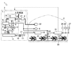
- Agricultural facility 2 is a facility for growing plants such as various vegetables, fruits and flowers. Specifically, a facility configured to form a closed space such as a vinyl house or a glass house can be mentioned.
- the trigeneration device 3 supplies electric power, heat, and carbon dioxide to the agricultural facility 2.
- the trigeneration device 3 is installed in the vicinity of the agricultural facility 2.
- the trigeneration apparatus 3 supplies carbon dioxide to the inside of the agricultural facility 2 through the carbon dioxide supply path 4 provided along the side surface of the agricultural facility 2.
- the trigeneration apparatus 3 includes an engine generator 5, waste heat recovery means 6 of the engine generator 5, exhaust gas carbon dioxide separation means 7 of the engine generator 5, and the like.
- the trigeneration apparatus 3 will be described as the carbon dioxide supply means.
- the present invention is not limited to this, and any device capable of supplying carbon dioxide such as a carbon dioxide cylinder may be used.
- the engine generator 5 included in the trigeneration apparatus 3 is configured to generate electric power by driving the generator with the driving force of the engine.
- the engine is not particularly limited as long as it contains carbon dioxide in the exhaust gas.
- a gas engine using a gas such as biomass gas as fuel can be used.
- the electric power obtained by the generator may be used as it is for various power loads 8 such as lighting in the agricultural facility 2, or is stored in a power sale or a storage battery when it is unnecessary, and if necessary. It may be designed to be used.
- Waste heat recovery means 6 recovers waste heat of the engine generator 5.
- the waste heat recovery means 6 is recovered from the cooling water circulation path 9 that cools the engine generator 5, the exhaust gas heat exchanger 10 that recovers waste heat from the exhaust gas, and the engine generator 5 and the exhaust gas heat exchanger 10.
- the waste heat heat exchanger 12 exchanges heat with the aqueous medium from the hot water storage tank 11 and the waste heat recovery path 13 supplies the waste heat recovered by the waste heat heat exchanger 12 to the hot water storage tank 11. ing.
- the cooling water circulation path 9 is used when the cooling water that has become high temperature after cooling the engine generator 5 passes through the exhaust heat exchanger 10 and then passes through the waste heat heat exchanger 12.
- the waste heat heat exchanger 12 is configured to exchange heat with the aqueous medium from the hot water tank 11.
- the cooling water having a low temperature after the heat exchange cools the engine generator 5 again by the pump 14 and then repeats circulation from the exhaust gas heat exchanger 10 to the waste heat heat exchanger 12.
- the waste heat recovery path 13 supplies the aqueous medium taken out from the hot water storage tank 11 to the waste heat heat exchanger 12 by the pump 15, recovers the waste heat of the engine generator 5 to make hot water, and then stores the hot water. It is configured to return to the inside of the tank 11.
- the hot water medium stored in the hot water tank 11 is sent to the heater 16 via the heat supply path 17 and radiated by the heater 16, and then the aqueous medium whose temperature has decreased is returned to the hot water tank 11 by the pump 18. .
- the trigeneration device 3 can heat the agricultural facility 2.
- the carbon dioxide separating means 7 separates carbon dioxide from the exhaust gas of the engine generator 5 and supplies it to the agricultural facility 2.
- the carbon dioxide separation means 7 includes an exhaust gas supply path 19 for supplying exhaust gas from the engine generator 5, a switching valve 20 for switching the direction of supplying exhaust gas, and a pressure-type separation method (PSA method) using an adsorbent. Is constituted by a carbon dioxide separator 21 that adsorbs components other than carbon dioxide, and a carbon dioxide supply path 4 that supplies carbon dioxide from the carbon dioxide separator 21.
- the exhaust gas released to the atmosphere from the engine generator 5 is switched to a state in which the exhaust gas is supplied to the carbon dioxide separator 21 by the switching valve 20, whereby the carbon dioxide is separated by the carbon dioxide separator 21.
- the carbon dioxide separator 7 can supply carbon dioxide from a carbon dioxide supply duct 22 provided in the agricultural facility.
- the trigeneration apparatus 3 can promote photosynthesis of the plant 23 cultivated in the agricultural facility by supplying carbon dioxide to the agricultural facility 2.
- the thermo camera shooting target changing device 24 changes the shooting target of the thermo camera 25 by changing the position and shooting direction of the thermo camera 25.
- the thermo camera shooting target changing device 24 is provided in the vicinity of the plant 23 to be measured.
- the thermo camera shooting target changing device 24 is provided with a thermo camera 25 via an actuator that can change the vertical position of the thermo camera 25 and change the shooting direction of the thermo camera 25.
- it is good also as a structure which can provide the thermocamera imaging
- the thermo camera 25 captures a temperature distribution of thermal energy radiated from an object.
- the thermo camera 25 is configured to photograph the temperature distribution of the leaves of the plant 23 and to change the leaves of the plant 23 to be photographed by the thermo camera photographing target changing device 24.
- the thermo camera 25 is connected to the control device 31, and the photographed temperature distribution is sent to the control device 31.
- the facility thermometer 26 detects the temperature in the agricultural facility.
- the in-facility thermometer 26 is connected to the control device 31, and the detected temperature is sent to the control device 31.
- sensors such as an outside air thermometer 27, a medium thermometer 28, and a carbon dioxide concentration meter 29 are provided in the agricultural facility 2, and the measured information is used for the growth of the plant 23.
- the outside air thermometer 27 detects the temperature outside the agricultural facility 2
- the medium thermometer 28 detects the temperature of the medium 30 in the agricultural facility 2
- the carbon dioxide concentration meter 29 detects the carbon dioxide concentration in the agricultural facility.
- the outside air thermometer 27, the culture medium thermometer 28, and the carbon dioxide concentration meter 29 are connected to the control device 31, and the detected value is sent to the control device 31.
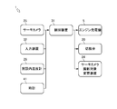
- control device 31 included in the carbon dioxide fertilizer application device 1 will be described with reference to FIG.
- the control device 31 controls the optimal supply amount of carbon dioxide in accordance with the photosynthesis state of the plant 23.
- the control device 31 may actually have a configuration in which a CPU, a ROM, a RAM, an HDD, and the like are connected by a bus, or may be configured by a one-chip LSI or the like.
- the control device 31 stores various programs and data for control.
- the control device 31 is connected to the thermo camera 25, and can acquire the temperature distribution of the leaves taken by the thermo camera 25.
- the control device 31 is connected to the in-facility thermometer 26, and can acquire the temperature in the agricultural facility detected by the in-facility thermometer 26.
- the control device 31 is connected to the clock 41 and can acquire the current time.
- the control device 31 is connected to the engine generator 5 and can control the supply amount of carbon dioxide by controlling the engine load or the operating state of the engine generator 5.
- the control device 31 is connected to the switching valve 20 and can control the supply amount of carbon dioxide by switching the switching valve 20.
- the leaf 33 is an organ that performs photosynthesis and respiration of the plant 23.
- the leaf 33 includes a leaf vein portion 34, a leaf blade portion A, a pore 35, and the like.
- the vein portion 34 is connected to the vascular bundle of the stem to supply water and nutrients, and carries synthetic products such as starch.
- the leaf vein portion 34 runs from the base of the leaf 33 to the tip thereof, and the leaf vein portion 34 branches laterally along the way.
- the leaf blade part A is the main body of the leaf 33 and is a main place for photosynthesis of the plant 23.
- Leaf blade part A is a part which is separated from the stem and extends to the side.
- the leaf vein portion 34 passes through the inside of the leaf blade portion A.
- the pores 35 exchange gas with the outside for breathing and transpiration.
- the pore 35 has a structure in which two cells (guard cells) face the lip shape, and the size of the pore 35 is adjusted by changing the shape of the guard cells.
- Carbon dioxide is mainly supplied through the pores 35.
- oxygen generated by the photosynthesis of the plant 23 performed inside the leaf 33 is also discharged from the pores 35, and similarly, the release of water vapor into the air by transpiration is performed mainly through the pores 35.
- One of the elements that adjust the opening and closing of the pores 35 is water. Specifically, when there is water stress, the plant 23 suppresses the transpiration by closing the pores 35 and delays the moisture reduction in the body. Water stress is stress that the plant 23 receives when moisture is insufficient, and occurs when the soil is dry or when the humidity is lower than the appropriate humidity.
- the temperature distribution of the leaves photographed by the thermo camera 25 also indicates that the darker the color, the higher the temperature, as in the case without water stress. Since the leaf 33 closes the pores and suppresses transpiration, the temperatures of the vein portion 34 and the leaf blade portion A both rise, and the temperature difference decreases.
- the temperature of the leaf vein portion 34 and the leaf blade portion A is compared between the case where there is no water stress and the case where there is water stress.
- the leaf 33 has a temperature of the leaf vein portion 34 higher than the air temperature, and the temperature of the leaf blade portion A is slightly higher than the air temperature.
- both the temperature of the leaf vein portion 34 and the leaf blade portion A rise, and the temperature difference decreases. This is because when there is water stress, the pores are closed to retain moisture, and the amount of latent heat transfer due to transpiration is reduced.
- the temperature difference between the leaf vein portion 34 and the leaf blade portion A decreases (see double arrow B).
- the control device 31 determines whether it is a photosynthesis possible time based on the current time acquired from the clock 41.
- the photosynthesizable time is the daytime, for example, from 6:00 to 18:00.
- the control device 31 performs control for reducing the engine load of the engine generator 5 or switching of the switching valve 20 to thereby reduce carbon dioxide. Reduce supply or cut off supply.
- the photosynthesizable time varies depending on the season and region, so the sunrise and sunset times vary, so the operator can arbitrarily set the photosynthesizable time, or the control device 31 can automatically synthesize photos according to the season. It is good also as a structure which sets time.
- the control device 31 uses the image of the temperature distribution photographed by the thermo camera 25 (see FIGS. 5A and 5B) to recognize the leaf vein part 34 and the blade part A by image recognition. Determine the position.
- the control device 31 reduces the temperature difference between the leaf vein portion 34 and the leaf blade portion A, so whether there is water stress based on the temperature difference between the leaf vein portion 34 and the leaf blade portion A. That is, it is determined whether or not the plant 23 is performing photosynthesis (existence of transpiration).
- the control device 31 measures the leaf temperature from the image captured by the thermo camera 25.
- the control device 31 calculates the average temperature of the part recognized as the leaf by the image recognition as the leaf temperature. Since the temperature difference between the air temperature (the temperature in the facility when the plant 23 is in the facility) and the leaf temperature has a positive correlation with the photosynthesis rate of the plant 23, the control device 31 determines the temperature in the agricultural facility. Based on the temperature difference from the leaf temperature, the photosynthesis rate of the plant 23 is determined.
- the control device 31 controls the supply amount of carbon dioxide by controlling the engine load or operating state of the engine generator 5 or switching the switching valve 20 using the determined photosynthesis speed of the plant 23 as an index.
- control device 31 determines that there is water stress and the plant 23 is not performing photosynthesis (no transpiration)
- the control device 31 performs control for reducing the engine load of the engine generator 5 or switching of the switching valve 20. By performing, the supply amount of carbon dioxide is reduced or the supply is interrupted. As a result, the control device 31 supplies an appropriate amount of carbon dioxide to the plant 23 in accordance with the actual state of photosynthesis.
- the carbon dioxide fertilizer application device 1 is based on the temperature difference between the leaf vein portion 34 and the leaf blade portion A of the plant 23 in consideration of the external environment for photosynthesis of the plant 23 by a simple method.
- the implementation status of the photosynthesis of the plant 23 is determined.
- carbon dioxide contained in the exhaust gas of the engine is supplied to the plant 23. Thereby, it is possible to appropriately control the supply amount of carbon dioxide using the trigeneration system.
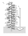
- thermo camera 25 Next, with reference to FIG. 6 and FIG. 7, a photographing method of the thermo camera 25 will be described.
- thermo camera 25 is photographing the back side of the leaf of the tomato 36.
- the thermo camera 25 grows the stem of the tomato 36, it is effective to promote photosynthesis in the vicinity of the growth point 38 (the tip of the stem). 6 (a)).
- the operator operates the input device 32 to move the thermo camera 25 upward (see arrow C), and changes the imaging target of the thermo camera 25 to the leaf 37b near the growth point 38. (See FIG. 6B).
- the control device 31 promotes the growth of the stem and root of the tomato 36 by controlling the supply amount of carbon dioxide based on the photosynthesis state of the leaf at a position suitable for the growth of the stem and root of the tomato 36.
- thermo camera 25 is photographing the back side of the leaf of the tomato 36 that has been fruited.
- the operator operates the input device 32 to set the photographing target of the thermo camera 25 to the upper leaf 37c with reference to the position of the fruit 39 of the tomato 36.
- the control device 31 promotes the growth of the fruit 39 of the tomato 36 by controlling the supply amount of carbon dioxide based on the photosynthesis state of the leaf at a position suitable for the growth of the fruit 39 of the tomato 36.
- the carbon dioxide fertilizer application device 1 determines the state of photosynthesis of the plant 23 that is important for the growth of the plant 23. Thereby, according to the photosynthesis state of the plant 23, control of the supply amount of an appropriate carbon dioxide can be performed.
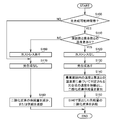
- step S ⁇ b> 100 the control device 31 determines whether or not it is a photosynthesis possible time zone from the time. As a result, when it is determined that it is the photosynthesis possible time zone, the control device 31 proceeds to step S110. On the other hand, if it is determined that the time period is not photosynthesis possible, the control device 31 proceeds to step S170.
- step S ⁇ b> 110 the control device 31 determines whether there is a temperature difference between the leaf vein portion 34 and the leaf blade portion A. In this determination, a threshold is set, and the control device 31 determines whether there is a temperature difference equal to or greater than the threshold. As a result, when it is determined that there is a temperature difference between the leaf vein portion 34 and the leaf blade portion A, the control device 31 proceeds to step S120. On the other hand, if it is determined that there is no temperature difference between the leaf vein portion 34 and the leaf blade portion A, the control device 31 proceeds to step S160.
- step S120 the control device 31 determines that there is no water stress in the plant 23, and proceeds to step S130.
- step S130 the control device 31 determines that the plant 23 is performing photosynthesis, and proceeds to step S140.
- step S140 the control device 31 calculates the supply amount of carbon dioxide using the photosynthetic rate determined based on the temperature difference between the temperature in the agricultural facility and the leaf temperature as an index, and proceeds to step S150.
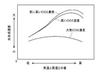
- the control device 31 calculates the supply amount of carbon dioxide so as to increase the photosynthesis rate based on the relationship between the temperature difference between the air temperature and the leaf temperature and the photosynthesis rate (see FIG. 9).
- step S150 the control device 31 performs control to supply the supply amount of carbon dioxide calculated in S140, and ends the control processing of the carbon dioxide fertilizer application device 1.
- step S160 the control device 31 determines that there is water stress of the plant 23, and proceeds to step S170.
- step S170 the control device 31 determines that the plant 23 is not performing photosynthesis, and proceeds to step S180.
- step S180 the control device 31 performs control to reduce the supply amount of carbon dioxide or control to cut off the supply, and terminates the control processing of the carbon dioxide fertilizer application device 1.
- the present invention can be used in a carbon dioxide fertilizer for facilities that grow plants.
Landscapes
- Life Sciences & Earth Sciences (AREA)
- Chemical & Material Sciences (AREA)
- Chemical Kinetics & Catalysis (AREA)
- Environmental Sciences (AREA)
- Biodiversity & Conservation Biology (AREA)
- Botany (AREA)
- Ecology (AREA)
- Forests & Forestry (AREA)
- Cultivation Of Plants (AREA)
- Greenhouses (AREA)
Abstract
植物の光合成の状態に合わせて、最適な二酸化炭素の供給量の制御を行うことができる二酸化炭素施肥装置を提供する。 二酸化炭素施肥装置1は、植物23の葉脈部34と葉身部Aとの温度差と時刻とに基づいて、植物23の光合成の状態を判定し、農業施設内の温度と植物23の葉温との温度差に基づいて植物23の光合成の速度を判定し、判定した植物23の光合成の速度を指標として、植物23の光合成の状態に基づいて、植物23を生育させる農業施設内への二酸化炭素の供給量を制御する。
Description
本発明は、二酸化炭素施肥装置に関する。詳しくは、植物を生育させる施設の二酸化炭素施肥装置に関する。
従来、植物の光合成の基質として二酸化炭素があり、光合成の速度は二酸化炭素の濃度に影響を受ける。光合成に必要な二酸化炭素が不足する場合、光合成の速度が減少する。農産物生産において、二酸化炭素を植物へ施肥して二酸化炭素の濃度を高く保ち、光合成の速度を増大させ、生育を促進することで収量増加および品質向上を達成することを二酸化炭素施肥という。二酸化炭素施肥技術として、植物の葉の近傍に十分な二酸化炭素を供給できる二酸化炭素マイクロバブル含有水供給方法および二酸化炭素マイクロバブル含有水供給装置が知られている。例えば、特許文献1に記載の如くである。
特許文献1に記載の二酸化炭素マイクロバブル含有水供給方法は、マイクロバブル発生装置に二酸化炭素と水とを導入して二酸化炭素マイクロバブル含有水を生成し、この二酸化炭素マイクロバブル含有水を噴霧ダクトで植物の局所に対して微小水滴として吐出する。
特許文献1に記載の技術において、二酸化炭素マイクロバブル含有水供給装置は、サーモグラフィなどで葉温を測定し、葉温が所定値を超えたときに二酸化炭素マイクロバブル含有水を噴霧する。これによって、二酸化炭素マイクロバブル含有水供給装置は、植物が多くの光を受けているときに多くの二酸化炭素を供給し光合成を促進する。しかし、植物が光を受けて葉温が高い場合でも、水分が不足する水ストレスが生じているときは、植物は水分を保持するため気孔を閉鎖し、気孔から二酸化炭素が取り込まれず、光合成の速度が著しく低下する。そこで、水ストレスが生じ光合成を実際に行えない場合でも、最適な二酸化炭素の供給量の制御を行うことができる二酸化炭素施肥装置が求められていた。
本発明の目的は、植物の光合成の状態に合わせて、最適な二酸化炭素の供給量の制御を行うことができる二酸化炭素施肥装置の提供を目的とする。
本発明の解決しようとする課題は以上の如くであり、次にこの課題を解決するための手段を説明する。
即ち、二酸化炭素施肥装置は、植物の葉脈部と葉身部との温度差に基づいて、植物の光合成の状態を判定し、植物の光合成の状態に基づいて、植物を生育させる施設内への二酸化炭素の供給量を制御するものである。
二酸化炭素施肥装置は、施設内の温度と植物の葉温との温度差に基づいて、植物の光合成の速度を判定し、時刻に基づいて植物の光合成の状態を判定し、植物の光合成の速度を指標として、植物の光合成の状態に基づいて、植物を生育させる施設内への二酸化炭素の供給量を制御するものである。
二酸化炭素施肥装置は、エンジン発電機と、エンジン発電機の廃熱回収手段と、エンジン発電機の排気ガスの二酸化炭素分離手段と、を備えたエネルギー供給装置により二酸化炭素を供給するものである。
二酸化炭素施肥装置は、植物の生育状態に応じて、葉脈部と葉身部との温度差を計測する対象の葉を変更するものである。
本発明は、以下に示すような効果を奏する。
二酸化炭素施肥装置においては、植物の光合成が実際に行われているか否かが判定される。これにより、植物の光合成の状態に合わせて、最適な二酸化炭素の供給量の制御を行うことができる。
二酸化炭素施肥装置においては、簡単な手法により植物の光合成を行うための外部環境が考慮されて、植物の光合成が実際に行われているか否かが判定される。これにより、植物の光合成の状態に合わせて、更に最適な二酸化炭素の供給量の制御を行うことができる。
二酸化炭素施肥装置においては、エンジンから生産される電力と熱と二酸化炭素とを利用するトリジェネレーションシステムにより二酸化炭素が植物に供給される。これにより、トリジェネレーションシステムを用いて、植物の光合成の状態に合わせて、最適な二酸化炭素の供給量の制御を行うことができる。
二酸化炭素施肥装置においては、植物の生育に効果的な位置の葉における、植物の光合成の状態が判定される。これにより、植物の光合成の状態に合わせて、最適な二酸化炭素の供給量の制御を行うことができる。
以下に、図1および図2を用いて、二酸化炭素施肥装置の一実施形態に係る二酸化炭素施肥装置1の全体構成について説明する。
農業施設2は、各種野菜、果物、花等の植物を生育させる施設である。具体的には、ビニールハウス、グラスハウスなどの閉塞された空間を形成するように構成された施設が挙げられる。
トリジェネレーション装置3は、農業施設2に電力、熱、および二酸化炭素を供給するものである。トリジェネレーション装置3は、農業施設2の近傍に設置される。トリジェネレーション装置3は、農業施設2の側面に沿って設けられている二酸化炭素供給経路4を通じて農業施設2内部へ二酸化炭素を供給している。トリジェネレーション装置3は、エンジン発電機5、エンジン発電機5の廃熱回収手段6、エンジン発電機5の排気ガスの二酸化炭素分離手段7等を具備する。なお、本実施形態においては、二酸化炭素供給手段としてトリジェネレーション装置3について説明を行うが、これに限定されるものではなく、二酸化炭素ボンベ等の二酸化炭素を供給できるものであればよい。
トリジェネレーション装置3が具備するエンジン発電機5は、エンジンの駆動力によって発電機を駆動して電力を生じるものである。エンジンとしては、排気ガスに二酸化炭素を含むものであれば、特に限定されるものではなく、例えば、バイオマスガスなどのガスを燃料とするガスエンジンを使用することができる。また、発電機によって得られた電力は、そのまま農業施設2内の照明等の各種電力負荷8に使用するものであってもよいし、不必要時に売電または蓄電池に蓄電し、必要に応じて使用するようになされたものであってもよい。
廃熱回収手段6は、エンジン発電機5の廃熱を回収するものである。廃熱回収手段6は、エンジン発電機5を冷却する冷却水循環経路9と、排気ガスからの廃熱を回収する排気ガス熱交換器10と、エンジン発電機5および排気ガス熱交換器10から回収した廃熱を貯湯槽11からの水媒体と熱交換する廃熱熱交換器12と、廃熱熱交換器12で回収した廃熱を貯湯槽11へ供給する廃熱回収経路13とによって構成されている。
冷却水循環経路9は、エンジン発電機5を冷却した後の高温となった冷却水が、排気ガス熱交換器10を通過してさらに高温となった後、廃熱熱交換器12を通過する際、廃熱熱交換器12において、貯湯槽11からの水媒体と熱交換を行うように構成されている。熱交換後、低温となった冷却水は、ポンプ14によって再度エンジン発電機5を冷却し、その後、排気ガス熱交換器10から廃熱熱交換器12へ循環を繰り返すように構成されている。
一方、廃熱回収経路13は、貯湯槽11から取り出した水媒体をポンプ15によって廃熱熱交換器12へ供給し、エンジン発電機5の廃熱を回収して高温のお湯とした後、貯湯槽11の内部へ戻すように構成されている。貯湯槽11に蓄熱され温水媒体は、熱供給経路17を経由し暖房器16へ送られ暖房器16で放熱した後に、温度が低下した水媒体をポンプ18によって、貯湯槽11の内部へ戻される。このようにして、トリジェネレーション装置3は、農業施設2を暖房できる。
二酸化炭素分離手段7は、エンジン発電機5の排気ガスから二酸化炭素を分離し、農業施設2に供給するものである。二酸化炭素分離手段7は、エンジン発電機5から排気ガスを供給する排気ガス供給経路19と、排気ガスを供給する方向を切り換える切換弁20と、吸着剤を用いた圧力式分離方法(PSA法)により二酸化炭素以外の成分を吸着する二酸化炭素分離装置21と、二酸化炭素分離装置21から二酸化炭素を供給する二酸化炭素供給経路4とによって構成されている。エンジン発電機5から大気解放される排気ガスは、切換弁20によって二酸化炭素分離装置21に排気ガスを供給する状態に切り換えることで、二酸化炭素分離装置21により二酸化炭素が分離される。そして、二酸化炭素分離手段7は、農業施設内に設けた二酸化炭素供給ダクト22から、二酸化炭素を供給できる。トリジェネレーション装置3は、農業施設2に二酸化炭素を供給することで、農業施設内で栽培する植物23の光合成を促進することができる。
サーモカメラ撮影対象変更装置24は、サーモカメラ25の位置や撮影方向を変更して、サーモカメラ25の撮影対象を変更するものである。サーモカメラ撮影対象変更装置24は、計測する対象の植物23の近傍に設けられている。サーモカメラ撮影対象変更装置24は、サーモカメラ25の上下の位置を変更可能、かつサーモカメラ25の撮影方向を変更可能なアクチュエータを介してサーモカメラ25が設けられている。なお、サーモカメラ撮影対象変更装置24を台車やロボット等に設け、台車やロボット等を移動させて計測する対象の植物23を変更可能な構成としてもよい。
サーモカメラ25は、物体から放射される熱エネルギーの温度分布を撮影するものである。サーモカメラ25は、植物23の葉の温度分布を撮影し、サーモカメラ撮影対象変更装置24により撮影対象となる植物23の葉を変更可能に構成されている。サーモカメラ25は、制御装置31と接続され、撮影した温度分布は制御装置31に送られる。
施設内温度計26は、農業施設内の温度を検出するものである。施設内温度計26は、制御装置31と接続され、検出した温度は制御装置31に送られる。
また、外気温度計27、培地温度計28、および二酸化炭素濃度計29等のセンサーが農業施設2に設けられ、計測された情報が植物23の生育に利用される。外気温度計27は農業施設2の外部の温度を検出し、培地温度計28は農業施設2の培地30の温度を検出し、二酸化炭素濃度計29は農業施設内の二酸化炭素濃度を検出する。外気温度計27、培地温度計28、および二酸化炭素濃度計29は、制御装置31と接続され、検出した値は、制御装置31に送られる。
次に、図3を用いて、二酸化炭素施肥装置1が具備する制御装置31について説明する。
制御装置31は、植物23の光合成の状態に合わせて、最適な二酸化炭素の供給量の制御を行うものである。制御装置31は、実体的には、CPU、ROM、RAM、HDD等がバスで接続される構成であってもよく、あるいはワンチップのLSI等からなる構成であってもよい。制御装置31は、制御するために種々のプログラムやデータが格納されている。
制御装置31は、サーモカメラ25に接続され、サーモカメラ25が撮影した葉の温度分布を取得することができる。
制御装置31は、入力装置32に接続されている。入力装置32には、キーボードやマウスが含まれており、オペレータによる入力に用いられる。
制御装置31は、施設内温度計26に接続され、施設内温度計26が検出した農業施設内の温度を取得することができる。
制御装置31は、時計41に接続され、現時点の時刻を取得することができる。
制御装置31は、エンジン発電機5に接続され、エンジン発電機5のエンジン負荷もしくは運転状態を制御することにより二酸化炭素の供給量を制御することができる。
制御装置31は、切換弁20に接続され、切換弁20を切り換えることにより二酸化炭素の供給量を制御することができる。
制御装置31は、サーモカメラ撮影対象変更装置24に接続され、サーモカメラ25の撮影対象を変更することができる。
次に、図4を用いて、葉の構成について説明する。なお、本実施例においては、植物23はトマトであるものとして説明するが、これに限定されるものではなく、葉脈部34と葉身部Aと気孔35とを備える植物23であればよい。
葉33は、植物23の光合成や呼吸を行う器官である。葉33は、葉脈部34、葉身部A、気孔35等を備える。
葉脈部34は、茎の維管束と連結して水や養分を供給し、デンプンなどの合成産物を運ぶものである。葉脈部34は、葉33の根元から先端へ中心になる葉脈部34が走り、その途中で側方へ枝の葉脈部34が伸びる。
葉身部Aは、葉33の本体であり植物23の光合成の主要な場となっているものである。葉身部Aは、茎から分かれて側方に伸びている部分である。葉身部Aの内部に葉脈部34が通っている。
気孔35は、呼吸および蒸散のために、外部と気体の交換を行うものである。気孔35は、葉33の裏側の表皮に多く存在する。気孔35は、2つの細胞(孔辺細胞)が唇型に向かい合った構造になっており、孔辺細胞の形が変化することによって、気孔35の大きさが調節される。二酸化炭素は、主に気孔35を通じて供給される。さらに、葉33の内部で行われた植物23の光合成により生じた酸素も気孔35より排出されるほか、蒸散による空気中への水蒸気の放出も同様に、主に気孔35を通じて行われる。気孔35の開閉を調節する要素の一つに水がある。具体的には、植物23は、水ストレスがある場合、気孔35を閉じることで蒸散を抑え体内の水分減少を遅らせる。水ストレスとは、水分が不足するときに植物23が受けるストレスであり、土壌が乾燥している場合や、湿度が適正湿度より低下している場合に生じる。
次に、図5を用いて水ストレスがない場合と水ストレスがある場合との、葉33の温度について説明する。なお、葉33は光合成に必要な光を受けているものとする。
図5(a)に示すように、水ストレスがない場合、サーモカメラ25で撮影した葉の温度分布は、濃い色ほど高い温度であること表している。葉身部Aにある気孔が開いており蒸散が行われているため、葉身部Aは葉脈部34に比べて温度が低くなる。
図5(b)に示すように、水ストレスがある場合、サーモカメラ25で撮影した葉の温度分布も、水ストレスがない場合と同様に濃い色ほど高い温度であること表している。葉33は、気孔を閉じて蒸散を抑えるため、葉脈部34と葉身部Aの温度が共に上昇し、温度差が減少する。
図5(c)に示すように、グラフにより水ストレスがない場合と水ストレスがある場合とについて、葉脈部34と葉身部Aとの温度を比較する。葉33は、水ストレスがない場合、気温よりも葉脈部34の温度が高く、葉身部Aの温度は気温よりやや高い状態となる。葉33は、水ストレスがある場合、葉脈部34と葉身部Aの温度が共に上昇し、温度差が減少する。これは、水ストレスがある場合、水分を保持するために気孔が閉鎖して、蒸散による潜熱伝達量が減少するためである。水ストレスがない場合と水ストレスがある場合とを比較すると、葉脈部34と葉身部Aの温度差が減少する(両矢印B参照)。
次に、制御装置31が行う二酸化炭素の供給量の制御について説明する。
制御装置31は、時計41から取得する現時点の時刻に基づいて、光合成可能時間か否かを判定する。光合成可能時間とは、日中の時間であり、例えば6時から18時である。制御装置31は、光合成可能時間ではなく、植物23が光合成を行っていないと判定した場合、エンジン発電機5のエンジン負荷を減少させる制御、または切換弁20の切り換えを行うことにより、二酸化炭素の供給量を減少または供給を遮断させる。なお、光合成可能時間は、季節や地域によって日の出および日没時間が変わるため、オペレータにより光合成可能時間を任意に設定可能な構成としてもよいし、制御装置31が季節に応じて自動的に光合成可能時間を設定する構成としてもよい。
制御装置31は、光合成可能時間の場合、サーモカメラ25で撮影した温度分布の画像(図5(a)および図5(b)参照)から、画像認識により葉脈部34と葉身部Aとの位置を判定する。制御装置31は、水ストレスがある場合、葉脈部34と葉身部Aとの温度差が小さくなるため、葉脈部34と葉身部Aとの温度差に基づいて、水ストレスがあるか否か、つまり植物23が光合成を行っているか否か(蒸散の有無)を判定する。
制御装置31は、水ストレスがなく植物23が光合成を行っている(蒸散あり)と判定した場合、サーモカメラ25が撮影した画像から葉温を計測する。制御装置31は、画像認識により葉と認識した部分の平均温度を葉温として算出する。気温(植物23が施設内にある場合は、施設内の温度)と葉温との温度差が植物23の光合成の速度と正の相関があるため、制御装置31は、農業施設内の温度と葉温との温度差に基づいて、植物23の光合成の速度を判定する。制御装置31は、判定した植物23の光合成の速度を指標として、エンジン発電機5のエンジン負荷もしくは運転状態の制御、または切換弁20の切り換えを行うことにより、二酸化炭素の供給量を制御する。
制御装置31は、水ストレスがあり植物23が光合成を行っていない(蒸散なし)と判定した場合、制御装置31は、エンジン発電機5のエンジン負荷を減少させる制御、または切換弁20の切り換えを行うことにより、二酸化炭素の供給量を減少、または供給を遮断させる。これにより、制御装置31は、実際の光合成の状態に合わせて、適量の二酸化炭素を植物23に供給する。
このように構成することで、二酸化炭素施肥装置1は、簡単な手法により植物23の光合成を行うための外部環境を考慮し、植物23の葉脈部34と葉身部Aとの温度差に基づいて、植物23の光合成の実施状況が判定される。また、エンジンの排気ガスに含まれる二酸化炭素が植物23に供給される。これにより、トリジェネレーションシステムを用いて、適切な二酸化炭素の供給量の制御を行うことができる。
次に、図6および図7を用いて、サーモカメラ25の撮影方法について説明する。
図6に示すように、サーモカメラ25は、トマト36の葉の裏側を撮影している。サーモカメラ25は、トマト36の茎を成長させる場合、成長点38(茎の先端部)付近の光合成を促すことが効果的であるため、成長点38付近の葉37aを撮影している(図6(a)参照)。オペレータは、トマト36の茎が成長した場合、入力装置32を操作してサーモカメラ25を上に移動させ(矢印C参照)、サーモカメラ25の撮影対象を成長点38付近である葉37bに変更する(図6(b)参照)。制御装置31は、トマト36の茎や根の成長に適した位置の葉の光合成状態に基づいて、二酸化炭素の供給量を制御することで、トマト36の茎や根の成長を促進させる。
図7に示すように、サーモカメラ25は、結実したトマト36の葉の裏側を撮影している。トマト36の実を大きくするため、トマト36の実の位置を基準として上下の葉の光合成を促すことが効果的である。そのため、オペレータは、トマト36の実39を大きくする場合、入力装置32を操作し、サーモカメラ25の撮影対象をトマト36の実39の位置を基準として上の葉37cにする。制御装置31は、トマト36の実39の成長に適した位置の葉の光合成状態に基づいて、二酸化炭素の供給量を制御することで、トマト36の実39の成長を促進する。
このように構成することで、二酸化炭素施肥装置1は、植物23の生育に重要な葉の植物23の光合成の実施状況が判定される。これにより、植物23の光合成の状態に合わせて、適切な二酸化炭素の供給量の制御を行うことができる。
次に、図8および図9を用いて、二酸化炭素施肥装置1の制御装置31における二酸化炭素の供給量の制御について具体的に説明する。
ステップS100において、制御装置31は、時刻から光合成可能時間帯か否かを判断する。
その結果、光合成可能時間帯であると判定された場合、制御装置31はステップS110に移行させる。
一方、光合成可能時間帯でないと判定された場合、制御装置31はステップS170に移行させる。
その結果、光合成可能時間帯であると判定された場合、制御装置31はステップS110に移行させる。
一方、光合成可能時間帯でないと判定された場合、制御装置31はステップS170に移行させる。
ステップS110において、制御装置31は、葉脈部34と葉身部Aとの温度差があるか否かを判断する。なお、この判断においては閾値が設定されており、制御装置31は、閾値以上の温度差があるか否かを判断する。
その結果、葉脈部34と葉身部Aとの温度差があると判定された場合、制御装置31はステップS120に移行させる。
一方、葉脈部34と葉身部Aとの温度差がないと判定された場合、制御装置31はステップS160に移行させる。
その結果、葉脈部34と葉身部Aとの温度差があると判定された場合、制御装置31はステップS120に移行させる。
一方、葉脈部34と葉身部Aとの温度差がないと判定された場合、制御装置31はステップS160に移行させる。
ステップS120において、制御装置31は、植物23の水ストレスがないと判定しステップS130に移行させる。
ステップS130において、制御装置31は、植物23が光合成を行っていると判定しステップS140に移行させる。
ステップS140において、制御装置31は、農業施設内の温度と葉温との温度差に基づいて判定される光合成速度を指標として、二酸化炭素の供給量を算出しステップS150に移行させる。例えば、制御装置31は、気温と葉温との温度差と、光合成速度との関係(図9参照)に基づいて、光合成速度が速くなるように二酸化炭素の供給量を算出する。
ステップS150において、制御装置31は、S140で算出した供給量の二酸化炭素を供給する制御を行い二酸化炭素施肥装置1の制御の処理を終了させる。
ステップS160において、制御装置31は、植物23の水ストレスがあると判定しステップS170に移行させる。
ステップS170において、制御装置31は、植物23が光合成を行っていないと判定しステップS180に移行させる。
ステップS180において、制御装置31は、二酸化炭素の供給量を減少させる制御、または供給を遮断する制御を行い二酸化炭素施肥装置1の制御の処理を終了させる。
上述の実施形態は、代表的な形態を示したに過ぎず、一実施形態の骨子を逸脱しない範囲で種々変形して実施することができる。さらに種々なる形態で実施し得ることは勿論のことであり、本発明の範囲は、特許請求の範囲の記載によって示され、さらに特許請求の範囲に記載の均等の意味、および範囲内のすべての変更を含む。
本発明は、植物を生育させる施設の二酸化炭素施肥装置に利用可能である。
1 二酸化炭素施肥装置
23 植物
34 葉脈部
A 葉身部
23 植物
34 葉脈部
A 葉身部
Claims (4)
- 植物の葉脈部と葉身部との温度差に基づいて、前記植物の光合成の状態を判定し、
前記植物の光合成の状態に基づいて、前記植物を生育させる施設内への二酸化炭素の供給量を制御する二酸化炭素施肥装置。 - 前記施設内の温度と前記植物の葉温との温度差に基づいて、前記植物の光合成の速度を判定し、
時刻に基づいて前記植物の光合成の状態を判定し、
前記植物の光合成の速度を指標として、
前記植物の光合成の状態に基づいて、前記植物を生育させる施設内への二酸化炭素の供給量を制御する請求項1に記載の二酸化炭素施肥装置。 - エンジン発電機と、
前記エンジン発電機の廃熱回収手段と、
前記エンジン発電機の排気ガスの二酸化炭素分離手段と、を備えたエネルギー供給装置により二酸化炭素を供給する請求項1または請求項2に記載の二酸化炭素施肥装置。 - 前記植物の生育状態に応じて、前記葉脈部と葉身部との温度差を計測する対象の葉を変更する請求項1から請求項3のいずれか一項に記載の二酸化炭素施肥装置。
Priority Applications (1)
| Application Number | Priority Date | Filing Date | Title |
|---|---|---|---|
| CN201780066168.4A CN110191632B (zh) | 2017-01-23 | 2017-12-28 | 二氧化碳施肥装置 |
Applications Claiming Priority (2)
| Application Number | Priority Date | Filing Date | Title |
|---|---|---|---|
| JP2017009706A JP6642900B2 (ja) | 2017-01-23 | 2017-01-23 | 二酸化炭素施肥装置 |
| JP2017-009706 | 2017-01-23 |
Publications (1)
| Publication Number | Publication Date |
|---|---|
| WO2018135296A1 true WO2018135296A1 (ja) | 2018-07-26 |
Family
ID=62908642
Family Applications (1)
| Application Number | Title | Priority Date | Filing Date |
|---|---|---|---|
| PCT/JP2017/047290 Ceased WO2018135296A1 (ja) | 2017-01-23 | 2017-12-28 | 二酸化炭素施肥装置 |
Country Status (3)
| Country | Link |
|---|---|
| JP (1) | JP6642900B2 (ja) |
| CN (1) | CN110191632B (ja) |
| WO (1) | WO2018135296A1 (ja) |
Cited By (3)
| Publication number | Priority date | Publication date | Assignee | Title |
|---|---|---|---|---|
| US11632915B2 (en) | 2017-08-24 | 2023-04-25 | Pipp Mobile Storage Systems, Inc. | System for providing circulating air for a vertical gardening system |
| US11641810B2 (en) | 2017-08-24 | 2023-05-09 | Pipp Mobile Storage Systems, Inc. | System for providing circulating air for a vertical gardening system |
| US12041898B2 (en) | 2021-04-09 | 2024-07-23 | Pipp Mobile Storage Systems, Inc. | Air flow systems and methods for horticulture racks |
Families Citing this family (7)
| Publication number | Priority date | Publication date | Assignee | Title |
|---|---|---|---|---|
| JP6578492B1 (ja) * | 2018-11-28 | 2019-09-25 | 株式会社西部技研 | 二酸化炭素回収施用一体型発電機 |
| KR102248334B1 (ko) * | 2019-07-01 | 2021-05-06 | 서울대학교산학협력단 | 작물 위치별 엽 광합성 속도 분포 모델을 이용한 수직 환경 관리 시스템 및 방법 |
| JP7315958B2 (ja) * | 2020-01-23 | 2023-07-27 | 国立研究開発法人農業・食品産業技術総合研究機構 | 作物の撮影装置および作物の撮影方法 |
| CN111373960A (zh) * | 2020-03-26 | 2020-07-07 | 南京白龙有机农业科技开发有限公司 | 一种控制二氧化碳释放量的方法和装置 |
| JP7481678B2 (ja) * | 2020-12-22 | 2024-05-13 | 井関農機株式会社 | 果樹栽培設備 |
| JP7739047B2 (ja) * | 2021-05-25 | 2025-09-16 | エア・ウォーター株式会社 | 施設栽培の環境制御装置 |
| WO2025079592A1 (ja) * | 2023-10-13 | 2025-04-17 | 国立大学法人広島大学 | 植物の水ストレス診断方法 |
Citations (4)
| Publication number | Priority date | Publication date | Assignee | Title |
|---|---|---|---|---|
| JP2011050293A (ja) * | 2009-09-01 | 2011-03-17 | Ehime Univ | 二酸化炭素マイクロバブル含有水供給方法および二酸化炭素マイクロバブル含有水供給装置 |
| JP2012110315A (ja) * | 2010-11-25 | 2012-06-14 | Yoichi Kadokami | 二酸化炭素発生方法および装置 |
| JP2013111073A (ja) * | 2011-12-01 | 2013-06-10 | Mitsubishi Electric Plant Engineering Corp | レタス栽培システムおよび方法 |
| US20150282440A1 (en) * | 2014-04-04 | 2015-10-08 | Greenhouse Hvac Llc | Climate control system and method for a greenhouse |
Family Cites Families (9)
| Publication number | Priority date | Publication date | Assignee | Title |
|---|---|---|---|---|
| CN2232191Y (zh) * | 1995-08-25 | 1996-08-07 | 侯见丁 | 二氧化碳气肥集散器 |
| CN101116410B (zh) * | 2006-12-22 | 2013-08-07 | 万尤宝 | 调节空气中二氧化碳浓度抑制温室效应的方法及其装置 |
| CN102172178B (zh) * | 2011-03-25 | 2013-03-13 | 中国科学院南京地理与湖泊研究所 | 一种不同二氧化碳浓度对沉水植物生长影响的试验方法 |
| JP2013135657A (ja) * | 2011-12-27 | 2013-07-11 | Toyohashi Shubyo Kk | 園芸施設内のco2濃度を制御する装置 |
| JP2015228812A (ja) * | 2014-06-04 | 2015-12-21 | フルタ電機株式会社 | ハウス栽培の空気循環システム |
| CN104322320B (zh) * | 2014-09-28 | 2016-06-15 | 定远县金胜农业开发有限公司 | 温室及水产联合养殖智能控制系统 |
| CN104686135A (zh) * | 2015-02-06 | 2015-06-10 | 郑州师范学院 | 利用co2提高非洲菊切花品质的方法 |
| CN105794475A (zh) * | 2016-04-08 | 2016-07-27 | 黄庆辉 | 一种白皮黄肉番薯的高产种植方法 |
| CN106106011A (zh) * | 2016-06-17 | 2016-11-16 | 霍山县新元生态农业有限公司 | 一种葡萄、草莓和香菇的立体栽培方法 |
-
2017
- 2017-01-23 JP JP2017009706A patent/JP6642900B2/ja active Active
- 2017-12-28 WO PCT/JP2017/047290 patent/WO2018135296A1/ja not_active Ceased
- 2017-12-28 CN CN201780066168.4A patent/CN110191632B/zh active Active
Patent Citations (4)
| Publication number | Priority date | Publication date | Assignee | Title |
|---|---|---|---|---|
| JP2011050293A (ja) * | 2009-09-01 | 2011-03-17 | Ehime Univ | 二酸化炭素マイクロバブル含有水供給方法および二酸化炭素マイクロバブル含有水供給装置 |
| JP2012110315A (ja) * | 2010-11-25 | 2012-06-14 | Yoichi Kadokami | 二酸化炭素発生方法および装置 |
| JP2013111073A (ja) * | 2011-12-01 | 2013-06-10 | Mitsubishi Electric Plant Engineering Corp | レタス栽培システムおよび方法 |
| US20150282440A1 (en) * | 2014-04-04 | 2015-10-08 | Greenhouse Hvac Llc | Climate control system and method for a greenhouse |
Cited By (3)
| Publication number | Priority date | Publication date | Assignee | Title |
|---|---|---|---|---|
| US11632915B2 (en) | 2017-08-24 | 2023-04-25 | Pipp Mobile Storage Systems, Inc. | System for providing circulating air for a vertical gardening system |
| US11641810B2 (en) | 2017-08-24 | 2023-05-09 | Pipp Mobile Storage Systems, Inc. | System for providing circulating air for a vertical gardening system |
| US12041898B2 (en) | 2021-04-09 | 2024-07-23 | Pipp Mobile Storage Systems, Inc. | Air flow systems and methods for horticulture racks |
Also Published As
| Publication number | Publication date |
|---|---|
| JP6642900B2 (ja) | 2020-02-12 |
| CN110191632B (zh) | 2021-08-03 |
| JP2018117539A (ja) | 2018-08-02 |
| CN110191632A (zh) | 2019-08-30 |
Similar Documents
| Publication | Publication Date | Title |
|---|---|---|
| JP6642900B2 (ja) | 二酸化炭素施肥装置 | |
| US20200000045A1 (en) | Growing system mixing box | |
| Wieland et al. | Physiological ecology of three codominant successional annuals | |
| Feng et al. | Contrasting responses of two C4 desert shrubs to drought but consistent decoupling of photosynthesis and stomatal conductance at high temperature | |
| US20180132435A1 (en) | Hydroponic cultivation apparatus | |
| CN105843299B (zh) | 温室环境系统多变量区间控制方法 | |
| JP2015133971A (ja) | 植物栽培プラント | |
| JP2021527406A (ja) | 作物を栽培する方法及び装置 | |
| Challa et al. | Greenhouse climate control in the nineties | |
| Marcelis et al. | Simulating growth and development of tomato crop | |
| WO2019217592A1 (en) | Improved growing system mixing box | |
| Fernando et al. | Design of a fuzzy logic controller for a vent fan and growlight in a tomato growth chamber | |
| Bailey | Microclimate, physical processes and greenhouse technology | |
| Kempkes et al. | Heating system position and vertical microclimate distribution in chrysanthemum greenhouse | |
| NL1031357C2 (nl) | Nevelkas. | |
| CA3050794C (en) | Improved growing system mixing box | |
| CN212414058U (zh) | 一种控制二氧化碳释放量的装置 | |
| CN111373960A (zh) | 一种控制二氧化碳释放量的方法和装置 | |
| NL1038146C2 (nl) | Kas, veld, gewas, werkwijze, watergeefsysteem en regelsysteem voor toediening van vocht aan een gewas. | |
| Buwalda et al. | An energy efficient heating strategy for cut rose production based on crop tolerance to temperature fluctuations | |
| Le Quillec et al. | Benefits of a semi-closed greenhouse for tomato production in the West of France | |
| KR102553718B1 (ko) | 버퍼탱크 및 삼방밸브를 도입하여 냉각 효율을 높인 양액 냉각 장치 및 양액 냉각 장치의 동작 방법 | |
| Devakumar et al. | Effect of elevated CO2 concentration on seedling growth rate and photosynthesis in Hevea brasiliensis | |
| Carvalho et al. | Crop water stress index of cowpea under different water availability levels in Castanhal-PA | |
| KR20230044721A (ko) | 스마트 재배 환경 미러링 시스템 |
Legal Events
| Date | Code | Title | Description |
|---|---|---|---|
| 121 | Ep: the epo has been informed by wipo that ep was designated in this application |
Ref document number: 17892880 Country of ref document: EP Kind code of ref document: A1 |
|
| NENP | Non-entry into the national phase |
Ref country code: DE |
|
| 122 | Ep: pct application non-entry in european phase |
Ref document number: 17892880 Country of ref document: EP Kind code of ref document: A1 |