WO2018135279A1 - 空調システム - Google Patents
空調システム Download PDFInfo
- Publication number
- WO2018135279A1 WO2018135279A1 PCT/JP2017/047002 JP2017047002W WO2018135279A1 WO 2018135279 A1 WO2018135279 A1 WO 2018135279A1 JP 2017047002 W JP2017047002 W JP 2017047002W WO 2018135279 A1 WO2018135279 A1 WO 2018135279A1
- Authority
- WO
- WIPO (PCT)
- Prior art keywords
- conditioning system
- air conditioning
- flow rate
- heat exchanger
- rate control
- Prior art date
- Legal status (The legal status is an assumption and is not a legal conclusion. Google has not performed a legal analysis and makes no representation as to the accuracy of the status listed.)
- Ceased
Links
Images

Classifications
-
- F—MECHANICAL ENGINEERING; LIGHTING; HEATING; WEAPONS; BLASTING
- F24—HEATING; RANGES; VENTILATING
- F24F—AIR-CONDITIONING; AIR-HUMIDIFICATION; VENTILATION; USE OF AIR CURRENTS FOR SCREENING
- F24F5/00—Air-conditioning systems or apparatus not covered by F24F1/00 or F24F3/00, e.g. using solar heat or combined with household units such as an oven or water heater
- F24F5/0007—Air-conditioning systems or apparatus not covered by F24F1/00 or F24F3/00, e.g. using solar heat or combined with household units such as an oven or water heater cooling apparatus specially adapted for use in air-conditioning
- F24F5/001—Compression cycle type
-
- F—MECHANICAL ENGINEERING; LIGHTING; HEATING; WEAPONS; BLASTING
- F24—HEATING; RANGES; VENTILATING
- F24F—AIR-CONDITIONING; AIR-HUMIDIFICATION; VENTILATION; USE OF AIR CURRENTS FOR SCREENING
- F24F11/00—Control or safety arrangements
- F24F11/30—Control or safety arrangements for purposes related to the operation of the system, e.g. for safety or monitoring
- F24F11/41—Defrosting; Preventing freezing
-
- F—MECHANICAL ENGINEERING; LIGHTING; HEATING; WEAPONS; BLASTING
- F24—HEATING; RANGES; VENTILATING
- F24F—AIR-CONDITIONING; AIR-HUMIDIFICATION; VENTILATION; USE OF AIR CURRENTS FOR SCREENING
- F24F5/00—Air-conditioning systems or apparatus not covered by F24F1/00 or F24F3/00, e.g. using solar heat or combined with household units such as an oven or water heater
-
- F—MECHANICAL ENGINEERING; LIGHTING; HEATING; WEAPONS; BLASTING
- F25—REFRIGERATION OR COOLING; COMBINED HEATING AND REFRIGERATION SYSTEMS; HEAT PUMP SYSTEMS; MANUFACTURE OR STORAGE OF ICE; LIQUEFACTION SOLIDIFICATION OF GASES
- F25B—REFRIGERATION MACHINES, PLANTS OR SYSTEMS; COMBINED HEATING AND REFRIGERATION SYSTEMS; HEAT PUMP SYSTEMS
- F25B1/00—Compression machines, plants or systems with non-reversible cycle
-
- F—MECHANICAL ENGINEERING; LIGHTING; HEATING; WEAPONS; BLASTING
- F25—REFRIGERATION OR COOLING; COMBINED HEATING AND REFRIGERATION SYSTEMS; HEAT PUMP SYSTEMS; MANUFACTURE OR STORAGE OF ICE; LIQUEFACTION SOLIDIFICATION OF GASES
- F25B—REFRIGERATION MACHINES, PLANTS OR SYSTEMS; COMBINED HEATING AND REFRIGERATION SYSTEMS; HEAT PUMP SYSTEMS
- F25B13/00—Compression machines, plants or systems, with reversible cycle
-
- F—MECHANICAL ENGINEERING; LIGHTING; HEATING; WEAPONS; BLASTING
- F25—REFRIGERATION OR COOLING; COMBINED HEATING AND REFRIGERATION SYSTEMS; HEAT PUMP SYSTEMS; MANUFACTURE OR STORAGE OF ICE; LIQUEFACTION SOLIDIFICATION OF GASES
- F25B—REFRIGERATION MACHINES, PLANTS OR SYSTEMS; COMBINED HEATING AND REFRIGERATION SYSTEMS; HEAT PUMP SYSTEMS
- F25B47/00—Arrangements for preventing or removing deposits or corrosion, not provided for in another subclass
Definitions
- the present invention relates to an air conditioning system, and more particularly to an air conditioning system that cools electrical components using cooling piping.
- a compressor which is sequentially connected by a refrigerant pipe, an outdoor heat exchanger, an outdoor flow rate control device, a container, and an indoor heat exchanger, the refrigerant pipe between the container and the indoor heat exchanger is
- an air conditioning system including a cooling pipe having an end and an outlet end, and the cooling pipe is in contact with an electrical component through a metal plate.
- the temperature of the refrigerant flowing into the cooling pipe from the inlet end may be lower than the dew point temperature of the air, so that condensation occurs in the cooling pipe (especially the inlet end side). There is. In such a case, if condensed water drops on the electrical components of the air conditioning system, it causes problems such as a short circuit, which is not ideal.
- the present invention has been made in order to solve the above-described problems, and an object of the present invention is to provide an air conditioning system useful for suppressing dew condensation on a cooling pipe constituting a part of a refrigerant pipe.
- an air conditioning system includes a compressor, an outdoor heat exchanger, an outdoor flow rate control device, a container, and an indoor heat exchange that are sequentially connected by refrigerant piping.
- the refrigerant pipe between the container and the indoor heat exchanger includes a cooling pipe.
- the air conditioning system further includes a container pressure increasing pipe and a control unit.
- the container pressure increasing pipe is provided with a flow rate control member, and one end of the container pressure increasing pipe is connected between the compressor and the outdoor heat exchanger, and the other end is connected between the container and the outdoor flow rate control device.
- the control unit controls the operation of the air conditioning system. When the control unit determines that the cooling pipe dew condensation condition, which is a condition for causing condensation on the cooling pipe, is satisfied, the control unit increases the opening degree of the flow rate control member.
- the control unit when the control unit determines that the cooling pipe dew condensation condition is satisfied, the control unit increases the opening of the flow control member. Therefore, the pressure of the saturated liquid refrigerant whose subcooling degree is 0 ° C. at the outlet portion of the container rises, thereby increasing the temperature of the cooling pipe (for example, the outlet temperature), thereby suppressing condensation on the cooling pipe. It becomes easy to do. As a result, it is difficult for problems such as condensation to occur and cause a short circuit by dripping onto the electrical components and the like constituting the air conditioning system.
- the air conditioning system which concerns on the 2nd viewpoint of this invention is an air conditioning system which concerns on the 1st viewpoint of this invention, Comprising: When a control part judges that cooling pipe dew condensation conditions are satisfy
- the control can be simplified.
- the air conditioning system which concerns on the 3rd viewpoint of this invention is an air conditioning system which concerns on the 1st viewpoint of this invention, Comprising: When a control part judges that the piping dew condensation conditions are satisfy
- the outlet temperature of the cooling pipe can be made equal to or higher than the environmental temperature relatively quickly.
- the air conditioning system which concerns on the 4th viewpoint of this invention is an air conditioning system which concerns on the 1st viewpoint of this invention, Comprising: In refrigerant
- the air conditioning system according to the fourth aspect of the present invention can switch between the cooling operation and the heating operation as necessary.
- the air conditioning system according to the fifth aspect of the present invention is the air conditioning system according to any one of the first to fourth aspects of the present invention, and the flow rate control member is an electric valve or an electromagnetic valve.
- the flow rate control member can be easily configured.
- the air conditioning system according to the sixth aspect of the present invention is the air conditioning system according to any one of the first to fourth aspects of the present invention, and the outdoor heat exchanger is a water heat exchanger.
- the outdoor heat exchanger can be easily configured.
- An air conditioning system is the air conditioning system according to any one of the first to fourth aspects of the present invention, wherein the cooling pipe outlet temperature is lower than the environmental temperature in the cooling operation.
- the control unit determines that the cooling pipe dew condensation condition is satisfied.
- the air conditioning system includes a compressor, an outdoor heat exchanger, an outdoor flow rate control device, and an indoor heat exchanger that are sequentially connected by refrigerant piping.
- the refrigerant pipe between the outdoor flow rate control device and the indoor heat exchanger includes a cooling pipe.
- the air conditioning system further includes a pressure increasing pipe and a control unit.
- the pressure increasing pipe is provided with a flow rate control member, and one end of the pressure increasing pipe is connected between the compressor and the outdoor heat exchanger, and the other end is connected between the cooling pipe and the outdoor flow rate control device. .
- the control unit controls the operation of the air conditioning system. When the control unit determines that the cooling pipe dew condensation condition, which is a condition for causing condensation on the cooling pipe, is satisfied, the control unit increases the opening degree of the flow rate control member.
- the control unit when the control unit determines that the cooling pipe dew condensation condition is satisfied, the control unit increases the opening of the flow control member. Therefore, the pressure of the saturated liquid refrigerant whose supercooling degree of the inlet portion of the cooling pipe is 0 ° C. is increased, thereby increasing the temperature of the cooling pipe (for example, the outlet temperature). It becomes easy to suppress. As a result, it is difficult for problems such as condensation to occur and cause a short circuit by dripping onto the electrical components and the like constituting the air conditioning system.
- the air conditioning system which concerns on the 9th viewpoint of this invention is an air conditioning system which concerns on the 8th viewpoint of this invention, Comprising: When a control part judges that the piping dew condensation conditions are satisfy
- the control can be simplified.
- the control unit when it is determined that the cooling pipe dew condensation condition is satisfied, the control unit increases the opening degree of the flow rate control member.
- the pressure of the saturated liquid refrigerant in which the degree of supercooling at the outlet portion of the container is 0 ° C. increases, so the temperature of the cooling pipe (outlet temperature) rises and it becomes easy to suppress dew condensation on the cooling pipe.
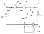
- FIG. 1 is a schematic diagram showing a circuit structure of an air conditioning system according to Embodiment 1 of the present invention.
- the air conditioning system includes a compressor 10, an outdoor heat exchanger 30, an outdoor flow rate control device CD, a container 40, and an indoor heat exchanger 50 that are sequentially connected by a refrigerant pipe R.
- the refrigerant pipe R between the container 40 and the indoor heat exchanger 50 includes a cooling pipe CR having an inlet end CRa and an outlet end CRb.
- cooling pipe CR is in contact with the electrical component through the metal plate MB.
- the air conditioning system further includes a container pressure increasing pipe BP and a control unit 60.
- a flow rate control member DM is provided in the container pressure increasing pipe BP. Further, one end of the container pressure increasing pipe BP is connected between the compressor 10 and the outdoor heat exchanger 30, and the other end is connected between the container 40 and the outdoor flow rate control device CD.
- the control unit 60 controls the operation of the air conditioning system.
- a water heat exchanger is adopted as the outdoor heat exchanger 30.
- an electric valve is adopted as the outdoor flow rate control device CD.
- an electric valve is used as the flow control member DM.
- the refrigerant compressed by the compressor 10 and discharged from the discharge end of the compressor 10 flows into the outdoor heat exchanger 30, performs heat exchange, decreases its temperature, and then flows through the flow control device CD. And flows into the container 40.
- the refrigerant flowing out of the container 40 flows into the cooling pipe CR, and cools the electrical components by using the cooling pipe CR.
- the refrigerant flows out of the cooling pipe CR, flows into the indoor heat exchanger 50, and performs heat exchange in the indoor heat exchanger 50.
- the refrigerant flows out of the indoor heat exchanger 50 and returns to the suction end of the compressor 10.
- the control unit 60 determines that the cooling pipe dew condensation condition is satisfied (for example, when the outlet temperature TL of the cooling pipe CR is lower than the environmental temperature Ta in the cooling operation), the control unit 60 opens the flow control member DM. Increase the degree.
- the control unit 60 determines that the cooling pipe dew condensation condition is satisfied, the control unit 60 increases the opening degree of the flow rate control member DM, and the outlet temperature TL of the cooling pipe CR is equal to the environmental temperature Ta. Determine whether they are equal. Even if the opening degree of the flow rate control member DM is maximized, if the outlet temperature TL of the cooling pipe CR cannot be made equal to the environmental temperature Ta, the control unit 60 reduces the opening degree of the outdoor flow rate control device CD.
- the reason why the opening degree of the outdoor flow control device CD is reduced after the opening degree of the flow rate control member DM is first increased is as follows. If the opening degree of the outdoor flow control device CD is first reduced, the pressure loss of the circuit increases, the pressure at the inlet of the cooling pipe CR decreases, and further, condensation occurs due to the temperature drop of the cooling pipe CR. End up.
- the control unit 60 increases the opening degree of the flow control member DM. Therefore, the pressure of the saturated liquid refrigerant whose subcooling degree is 0 ° C. at the outlet portion of the container rises, and as a result, the temperature (outlet temperature) of the cooling pipe CR rises, so dew condensation on the cooling pipe CR is suppressed. It becomes easy to do. As a result, it is difficult for problems such as condensation to occur and cause a short circuit by dripping onto the electrical components and the like constituting the air conditioning system.
- FIG. 2 is a schematic diagram showing a circuit structure of an air conditioning system according to Embodiment 2 of the present invention.
- the structure of the air conditioning system of this embodiment is basically the same as that of the above-described air conditioning system of Embodiment 1, and the difference is that the switching device 20 is installed in the air conditioning system of this embodiment.
- a switching device 20 that switches the air conditioning system between a cooling operation and a heating operation is installed in the refrigerant pipe R between the compressor 10 and the outdoor heat exchanger 30.
- One end of the container pressure increasing pipe BP is connected between the compressor 10 and the switching device 20, and the other end is connected between the container 40 and the outdoor flow rate control device CD.
- a four-way switching valve is employed as the switching device 20.
- the air conditioning system of the present embodiment can perform heating operation in addition to cooling operation and dew condensation suppression operation.
- the cooling operation and the dew condensation suppression operation are the same as the cooling operation and the dew condensation suppression operation of the first embodiment, respectively, the description is omitted here, and only the heating operation is described.
- -Heating operation Here, the flow control member DM is closed by the control unit 60, and the switching device 20 is switched to the state shown by the broken line in FIG.
- the refrigerant compressed by the compressor 10 and discharged from the discharge end of the compressor 10 flows into the indoor heat exchanger 50 through the switching device 20.
- the refrigerant whose temperature has decreased due to heat exchange in the indoor heat exchanger 50 then flows into the cooling pipe CR, and cools the electrical components by using the cooling pipe CR.
- the refrigerant flows out of the cooling pipe CR and flows through the container 40 and the flow rate control device CD.
- the refrigerant flows into the outdoor heat exchanger 30 and performs heat exchange in the outdoor heat exchanger 30.
- the refrigerant flows out of the outdoor heat exchanger 30 and returns to the suction end of the compressor 10 via the switching device 20.
- the outlet temperature TL of the cooling pipe CR is higher than the environmental temperature Ta.
- the control unit 60 increases the opening degree of the flow control member DM.
- the pressure of the saturated liquid refrigerant in which the degree of supercooling at the outlet portion of the container 40 is 0 ° C. increases, so that the temperature (outlet temperature) of the cooling pipe CR rises and dew condensation on the cooling pipe CR is suppressed. It becomes easy. As a result, it is difficult for dew condensation water to drip onto the electrical components and the like constituting the air conditioning system and cause problems such as a short circuit.
- the cooling operation and the heating operation can be switched as necessary.
- a water heat exchanger is employed as the outdoor heat exchanger 30, but the present invention is not limited to this, and an air heat exchanger may be employed.
- the controller 60 increases the opening degree of the flow rate control member DM and the outlet temperature TL of the cooling pipe CR is increased. It is determined whether or not it is equal to the environmental temperature Ta. If the outlet temperature TL of the cooling pipe CR cannot be made equal to the environmental temperature Ta even when the opening degree of the flow rate control member DM is maximized, the control unit 60 reduces the opening degree of the outdoor flow rate control device CD. is doing.
- the flow rate control member is not limited to this, and when it is determined that the cooling pipe dew condensation condition is satisfied, the control unit 60 causes the cooling pipe outlet temperature to be equal to or higher than the environmental temperature.
- the opening degree of the outdoor flow rate adjusting device may be reduced simultaneously with increasing the opening degree.
- the cooling pipe outlet temperature can be made equal to or higher than the environmental temperature relatively quickly.
- an electric valve is employed as the flow rate control member DM.
- the present invention is not limited to this, and an electromagnetic valve may be employed.
- the control unit 60 opens the flow rate control member DM and whether the outlet temperature TL of the cooling pipe CR is equal to or higher than the environmental temperature Ta. If the outlet temperature TL of the cooling pipe CR cannot be made equal to or higher than the environmental temperature Ta even if the flow rate control member DM is opened, the control unit 60 reduces the opening degree of the outdoor flow rate control device CD.
- the control unit 60 causes the cooling pipe outlet temperature to be equal to or higher than the environmental temperature.
- the opening degree of the outdoor flow rate adjusting device may be decreased simultaneously with opening the flow rate control member.
Landscapes
- Engineering & Computer Science (AREA)
- Mechanical Engineering (AREA)
- General Engineering & Computer Science (AREA)
- Physics & Mathematics (AREA)
- Thermal Sciences (AREA)
- Chemical & Material Sciences (AREA)
- Combustion & Propulsion (AREA)
- Life Sciences & Earth Sciences (AREA)
- Sustainable Development (AREA)
- Air Conditioning Control Device (AREA)
Abstract
Description
<実施形態1>
以下、図面を参照しながら、本発明の実施形態1にかかる空調システムについて説明する。図1は本発明の実施形態1に係る空調システムの回路構造を示す模式図である。
-冷房運転-
ここで、説明の便宜上、流量制御部材DMは閉められていると仮定する。
-結露抑制運転-
制御部60が冷却用配管結露条件を満たすと判断した時(例えば、冷房運転において、冷却用配管CRの出口温度TLが環境温度Taよりも低い時)、制御部60は流量制御部材DMの開度を大きくする。
<実施形態2>
以下、図2を参照して、本発明の実施形態2の空調システムについて説明する。図2は本発明の実施形態2に係る空調システムの回路構造を示す模式図である。
-暖房運転-
ここでは、制御部60によって流量制御部材DMが閉じられ、かつ、切換装置20が図2の破線で示す状態に切り換えられている。
<その他の実施形態>
実施形態1及び2の空調システムでは、冷却用配管CRと室外流量調節装置CDとの間に容器40を介在させているが、容器40を除去したものであってもよい。
20 切換装置
30 室外熱交換器
40 容器
50 室内熱交換器
60 制御部
R 冷媒配管
CD 室外流量調節装置
CR 冷却用配管
CRa 入口端
CRb 出口端
DM 流量制御部材
MB 金属板
Claims (9)
- 冷媒配管によって順に接続された圧縮機(10)と、室外熱交換器(30)と、室外流量調節装置(CD)と、容器(40)と、室内熱交換器(50)とを含み、前記容器(40)と前記室内熱交換器(50)の間の冷媒配管は冷却用配管(CR)を含む空調システムであって、
前記空調システムは、容器増圧配管(BP)と制御部(60)をさらに含み、前記容器増圧配管(BP)には流量制御部材(DM)が設けられ、かつ、前記容器増圧配管(BP)の一端は前記圧縮機(10)と前記室外熱交換器(30)の間に接続され、他端は前記容器(40)と前記室外流量調節装置(CD)の間に接続され、前記制御部(60)は前記空調システムの運転に対して制御を行い、
前記制御部(60)が前記冷却用配管(CR)に結露が発生する条件である冷却用配管結露条件を満たすと判断した時、前記制御部(60)は前記流量制御部材(DM)の開度を大きくすることを特徴とする、
空調システム。 - 前記制御部(60)が冷却用配管結露条件を満たすと判断した時、前記制御部(60)は、前記冷却用配管(CR)の出口温度が環境温度と等しくなるか、または環境温度より高くなるように、前記流量制御部材(DM)の開度を最大にした後、前記室外流量調節装置(CD)の開度を小さくすることを特徴とする、
請求項1に記載の空調システム。 - 前記制御部(60)が冷却用配管結露条件を満たすと判断した時、前記制御部(60)は前記流量制御部材(DM)の開度を大きくすると同時に、前記室外流量調節装置(CD)の開度を小さくすることを特徴とする、
請求項1に記載の空調システム。 - 前記圧縮機(10)と前記室外熱交換器(30)の間の冷媒配管には、前記空調システムを冷房運転と暖房運転とに切り換える切換装置(20)が設置され、
前記容器増圧配管(BP)の一端は前記圧縮機(10)と前記切換装置(20)の間に接続されることを特徴とする、
請求項1に記載の空調システム。 - 前記流量制御部材(DM)は電動弁または電磁弁であることを特徴とする、
請求項1から4のいずれか1項に記載の空調システム。 - 前記室外熱交換器(30)は水熱交換器であることを特徴とする、
請求項1から4のいずれか1項に記載の空調システム。 - 冷房運転において前記冷却用配管(CR)の出口温度が環境温度より低い時、前記制御部(60)は前記冷却用配管結露条件を満たすと判断することを特徴とする、
請求項1から4のいずれか1項に記載の空調システム。 - 冷媒配管によって順に接続された圧縮機(10)と、室外熱交換器(30)と、室外流量調節装置(CD)と、室内熱交換器(50)とを含み、前記室外流量調節装置(CD)と前記室内熱交換器(50)の間の冷媒配管は冷却用配管(CR)を含む空調システムであって、
前記空調システムは、増圧配管(BP)と制御部(60)をさらに含み、前記増圧配管には流量制御部材(DM)が設けられ、かつ、前記増圧配管(BP)の一端は前記圧縮機(10)と前記室外熱交換器(30)の間に接続され、他端は前記冷却用配管(CR)と前記室外流量調節装置(CD)の間に接続され、前記制御部(60)は前記空調システムの運転に対して制御を行い、
前記制御部(60)が前記冷却用配管(CR)に結露が発生する条件である冷却用配管結露条件を満たすと判断した時、前記制御部(60)は前記流量制御部材(DM)の開度を大きくすることを特徴とする、
空調システム。 - 前記制御部(60)が冷却用配管結露条件を満たすと判断した時、前記制御部(60)は、前記冷却用配管(CR)の出口温度が環境温度と等しくなるか、または環境温度より高くなるように、前記流量制御部材(DM)の開度を最大にした後、前記室外流量調節装置(CD)の開度を小さくすることを特徴とする、
請求項8に記載の空調システム。
Priority Applications (2)
| Application Number | Priority Date | Filing Date | Title |
|---|---|---|---|
| MYPI2019004085A MY196222A (en) | 2017-01-22 | 2017-12-27 | Air Conditioning System |
| AU2017395110A AU2017395110B2 (en) | 2017-01-22 | 2017-12-27 | Air conditioning system |
Applications Claiming Priority (2)
| Application Number | Priority Date | Filing Date | Title |
|---|---|---|---|
| CN201710053673.7A CN108344079A (zh) | 2017-01-22 | 2017-01-22 | 空调系统 |
| CN201710053673.7 | 2017-01-22 |
Publications (1)
| Publication Number | Publication Date |
|---|---|
| WO2018135279A1 true WO2018135279A1 (ja) | 2018-07-26 |
Family
ID=62908808
Family Applications (1)
| Application Number | Title | Priority Date | Filing Date |
|---|---|---|---|
| PCT/JP2017/047002 Ceased WO2018135279A1 (ja) | 2017-01-22 | 2017-12-27 | 空調システム |
Country Status (4)
| Country | Link |
|---|---|
| CN (1) | CN108344079A (ja) |
| AU (1) | AU2017395110B2 (ja) |
| MY (1) | MY196222A (ja) |
| WO (1) | WO2018135279A1 (ja) |
Families Citing this family (2)
| Publication number | Priority date | Publication date | Assignee | Title |
|---|---|---|---|---|
| CN113606821A (zh) * | 2021-08-31 | 2021-11-05 | 美的集团武汉暖通设备有限公司 | 空气源热泵设备、控制方法及存储介质 |
| CN113865137B (zh) * | 2021-09-08 | 2022-12-09 | 美的集团武汉暖通设备有限公司 | 一种空气源热泵系统及空气源热泵的控制方法 |
Citations (3)
| Publication number | Priority date | Publication date | Assignee | Title |
|---|---|---|---|---|
| JPS6454174A (en) * | 1987-08-26 | 1989-03-01 | Asahi Kogyosha | Dehumidification capacity control type cooling unit |
| WO2008059803A1 (en) * | 2006-11-13 | 2008-05-22 | Daikin Industries, Ltd. | Heat exchanging system |
| JP2016014512A (ja) * | 2014-07-03 | 2016-01-28 | ダイキン工業株式会社 | 冷凍装置 |
Family Cites Families (4)
| Publication number | Priority date | Publication date | Assignee | Title |
|---|---|---|---|---|
| CN101865552A (zh) * | 2010-06-22 | 2010-10-20 | 合肥天鹅制冷科技有限公司 | 一种空气调节设备 |
| JP5694018B2 (ja) * | 2011-03-16 | 2015-04-01 | 株式会社日本自動車部品総合研究所 | 冷却装置 |
| CN203964447U (zh) * | 2014-06-16 | 2014-11-26 | 广东美的暖通设备有限公司 | 热泵系统 |
| CN105928109A (zh) * | 2016-05-27 | 2016-09-07 | 珠海格力电器股份有限公司 | 一种具有模块换热装置的空调系统及具有其的空调 |
-
2017
- 2017-01-22 CN CN201710053673.7A patent/CN108344079A/zh active Pending
- 2017-12-27 AU AU2017395110A patent/AU2017395110B2/en active Active
- 2017-12-27 MY MYPI2019004085A patent/MY196222A/en unknown
- 2017-12-27 WO PCT/JP2017/047002 patent/WO2018135279A1/ja not_active Ceased
Patent Citations (3)
| Publication number | Priority date | Publication date | Assignee | Title |
|---|---|---|---|---|
| JPS6454174A (en) * | 1987-08-26 | 1989-03-01 | Asahi Kogyosha | Dehumidification capacity control type cooling unit |
| WO2008059803A1 (en) * | 2006-11-13 | 2008-05-22 | Daikin Industries, Ltd. | Heat exchanging system |
| JP2016014512A (ja) * | 2014-07-03 | 2016-01-28 | ダイキン工業株式会社 | 冷凍装置 |
Also Published As
| Publication number | Publication date |
|---|---|
| MY196222A (en) | 2023-03-23 |
| AU2017395110B2 (en) | 2019-09-19 |
| AU2017395110A1 (en) | 2019-09-12 |
| CN108344079A (zh) | 2018-07-31 |
Similar Documents
| Publication | Publication Date | Title |
|---|---|---|
| CA2615689C (en) | An air conditioning heat pump with secondary compressor | |
| EP3098540B1 (en) | Heat pump apparatus | |
| US10006647B2 (en) | Air conditioning system with distributor for a plurality of indoor units | |
| EP2891849A1 (en) | Heat reclaim for a multifunction heat pump and a multifunction air conditioner | |
| CN104220821B (zh) | 空调装置 | |
| CN105066537A (zh) | 多联机制热回油控制方法 | |
| CN104567099A (zh) | 空调器 | |
| JP2012107836A (ja) | 二元冷凍サイクル装置 | |
| JPWO2016139783A1 (ja) | 冷凍サイクル装置 | |
| WO2018142583A1 (ja) | 冷凍システム | |
| CN203518359U (zh) | 一种汽车热泵空调系统 | |
| EP3696473B1 (en) | Air conditioning device | |
| JP5157580B2 (ja) | 冷凍装置 | |
| WO2018135277A1 (ja) | 空調システム | |
| US20180372354A1 (en) | Method for Solving Charge Imbalance in Existing Split Heat Pump | |
| CN102338513B (zh) | 制冷系统和具有该制冷系统的冰箱 | |
| JP2015206553A (ja) | 冷凍サイクル装置 | |
| KR102080836B1 (ko) | 공기조화 시스템 | |
| WO2016189626A1 (ja) | 空気調和装置 | |
| AU2017395110B2 (en) | Air conditioning system | |
| US9267716B2 (en) | Heat exchanger and an air conditioning system having the same | |
| CN105509154A (zh) | 一种空调机及其控制方法 | |
| CN111578464B (zh) | 一种空调器 | |
| JP2016142453A (ja) | 空気調和機 | |
| JP2007032857A (ja) | 冷凍装置 |
Legal Events
| Date | Code | Title | Description |
|---|---|---|---|
| 121 | Ep: the epo has been informed by wipo that ep was designated in this application |
Ref document number: 17892274 Country of ref document: EP Kind code of ref document: A1 |
|
| NENP | Non-entry into the national phase |
Ref country code: DE |
|
| ENP | Entry into the national phase |
Ref document number: 2017395110 Country of ref document: AU Date of ref document: 20171227 Kind code of ref document: A |
|
| 122 | Ep: pct application non-entry in european phase |
Ref document number: 17892274 Country of ref document: EP Kind code of ref document: A1 |
|
| NENP | Non-entry into the national phase |
Ref country code: JP |