WO2018135183A1 - Coordinate input apparatus - Google Patents
Coordinate input apparatus Download PDFInfo
- Publication number
- WO2018135183A1 WO2018135183A1 PCT/JP2017/044409 JP2017044409W WO2018135183A1 WO 2018135183 A1 WO2018135183 A1 WO 2018135183A1 JP 2017044409 W JP2017044409 W JP 2017044409W WO 2018135183 A1 WO2018135183 A1 WO 2018135183A1
- Authority
- WO
- WIPO (PCT)
- Prior art keywords
- input
- touch pad
- coordinate
- vector
- finger
- Prior art date
Links
Images


Classifications
-
- G—PHYSICS
- G06—COMPUTING; CALCULATING OR COUNTING
- G06F—ELECTRIC DIGITAL DATA PROCESSING
- G06F3/00—Input arrangements for transferring data to be processed into a form capable of being handled by the computer; Output arrangements for transferring data from processing unit to output unit, e.g. interface arrangements
- G06F3/01—Input arrangements or combined input and output arrangements for interaction between user and computer
- G06F3/03—Arrangements for converting the position or the displacement of a member into a coded form
- G06F3/041—Digitisers, e.g. for touch screens or touch pads, characterised by the transducing means
- G06F3/0416—Control or interface arrangements specially adapted for digitisers
- G06F3/0418—Control or interface arrangements specially adapted for digitisers for error correction or compensation, e.g. based on parallax, calibration or alignment
- G06F3/04186—Touch location disambiguation
-
- G—PHYSICS
- G06—COMPUTING; CALCULATING OR COUNTING
- G06F—ELECTRIC DIGITAL DATA PROCESSING
- G06F3/00—Input arrangements for transferring data to be processed into a form capable of being handled by the computer; Output arrangements for transferring data from processing unit to output unit, e.g. interface arrangements
- G06F3/01—Input arrangements or combined input and output arrangements for interaction between user and computer
- G06F3/03—Arrangements for converting the position or the displacement of a member into a coded form
- G06F3/033—Pointing devices displaced or positioned by the user, e.g. mice, trackballs, pens or joysticks; Accessories therefor
- G06F3/0354—Pointing devices displaced or positioned by the user, e.g. mice, trackballs, pens or joysticks; Accessories therefor with detection of 2D relative movements between the device, or an operating part thereof, and a plane or surface, e.g. 2D mice, trackballs, pens or pucks
- G06F3/03547—Touch pads, in which fingers can move on a surface
-
- G—PHYSICS
- G06—COMPUTING; CALCULATING OR COUNTING
- G06F—ELECTRIC DIGITAL DATA PROCESSING
- G06F3/00—Input arrangements for transferring data to be processed into a form capable of being handled by the computer; Output arrangements for transferring data from processing unit to output unit, e.g. interface arrangements
- G06F3/01—Input arrangements or combined input and output arrangements for interaction between user and computer
- G06F3/03—Arrangements for converting the position or the displacement of a member into a coded form
- G06F3/041—Digitisers, e.g. for touch screens or touch pads, characterised by the transducing means
- G06F3/044—Digitisers, e.g. for touch screens or touch pads, characterised by the transducing means by capacitive means
-
- G—PHYSICS
- G06—COMPUTING; CALCULATING OR COUNTING
- G06F—ELECTRIC DIGITAL DATA PROCESSING
- G06F3/00—Input arrangements for transferring data to be processed into a form capable of being handled by the computer; Output arrangements for transferring data from processing unit to output unit, e.g. interface arrangements
- G06F3/01—Input arrangements or combined input and output arrangements for interaction between user and computer
- G06F3/048—Interaction techniques based on graphical user interfaces [GUI]
- G06F3/0487—Interaction techniques based on graphical user interfaces [GUI] using specific features provided by the input device, e.g. functions controlled by the rotation of a mouse with dual sensing arrangements, or of the nature of the input device, e.g. tap gestures based on pressure sensed by a digitiser
- G06F3/0488—Interaction techniques based on graphical user interfaces [GUI] using specific features provided by the input device, e.g. functions controlled by the rotation of a mouse with dual sensing arrangements, or of the nature of the input device, e.g. tap gestures based on pressure sensed by a digitiser using a touch-screen or digitiser, e.g. input of commands through traced gestures
Abstract
According to the present invention, V1 represents an input vector when dragging is carried out in the vicinity of the outer periphery of a touch pad 2. By means of an arithmetic unit 6, the input vector V1 is multiplied by a coordinate movement coefficient ACL, and an output vector V4 resulting from dragging in the vicinity of the outer periphery of the touch pad 2 by a short distance and an output vector V5 resulting from dragging in the vicinity of the outer periphery of the touch pad 2 by a long distance are set to be equal in length. The coordinate movement coefficient ACL is calculated by the product of a transmission function f(v) determined from a finger operation speed and a transmission function f(d) for increasing a coordinate movement amount.
Description
本発明は、タッチパッド等の座標入力装置に関する。
The present invention relates to a coordinate input device such as a touch pad.
従来より、ノート型パーソナルコンピュータ等の座標入力装置として、指で操作面をタッチすることによりクリック操作や画面のスクロール等を行うタッチパッドが知られている。また、近年では、スマートフォンやタブレット端末等の座標入力装置としてタッチパネルが用いられている。
Conventionally, as a coordinate input device such as a notebook personal computer, a touch pad that performs a click operation or a screen scroll by touching an operation surface with a finger is known. In recent years, touch panels have been used as coordinate input devices such as smartphones and tablet terminals.
このような人の指等で直感的に機器の操作が行える座標入力装置は、パーソナルコンピュータやスマートフォン等の情報端末に限らず、多くの機器に用いられるようになってきている。例えば、自動車において、カーナビゲーションの操作用、或いはオーディオ機器の操作用等に利用されている。
Such a coordinate input device that can intuitively operate a device with a person's finger or the like is not limited to an information terminal such as a personal computer or a smartphone, but has been used in many devices. For example, in a car, it is used for the operation of car navigation or the operation of audio equipment.
近年では、このような座標入力装置において、操作性を向上させる手法が種々提案されている。例えば、特許文献1では、指やタッチペン等の操作体が操作面に接触した接触状態と、操作面から指が離れた後、近接状態となった操作体の位置の情報を利用する技術が開示されている。
In recent years, various methods for improving the operability of such coordinate input devices have been proposed. For example, Patent Document 1 discloses a technology that uses information on a contact state in which an operating body such as a finger or a touch pen comes into contact with the operation surface, and information on a position of the operating body in a proximity state after the finger is released from the operation surface. Has been.
特許文献1に開示された座標入力装置では、操作面の接触状態において、操作体の移動方向、移動距離、及び移動速度に応じた速度で画面をスクロールし、接触状態から操作体が離れて近接状態となった際の近接位置を利用してベクトルを特定し、そのベクトルの方向又は長さに応じてスクロールの速度を変更している。特許文献1では、このような処理をすることにより、座標入力装置の操作性を向上させることができると記載されている。
In the coordinate input device disclosed in Patent Document 1, in the contact state of the operation surface, the screen is scrolled at a speed corresponding to the movement direction, the movement distance, and the movement speed of the operation body, and the operation body is separated from the contact state and approached. A vector is specified using the proximity position when the state is reached, and the scrolling speed is changed according to the direction or length of the vector. Patent Document 1 describes that the operability of the coordinate input device can be improved by performing such processing.
また、特許文献2では、操作面において操作体を操作できる十分な面積を確保できないような場合であっても、操作体の圧力を検知することによって、簡単に画像の移動表示に係る方向及び速度を決定することができるタッチパネル装置が開示されている。
Further, in Patent Document 2, even if it is not possible to secure a sufficient area for operating the operating tool on the operating surface, the direction and speed relating to the moving display of the image can be easily detected by detecting the pressure of the operating tool. A touch panel device capable of determining the above is disclosed.
このような座標入力装置によって操作される機器においては、操作のための座標入力装置と、操作された状態が表示される表示装置が離れている場合がある。例えば、自動車内の機器の操作において、シフトレバーの上面やステアリングホイール等にタッチパッドを設け、そのタッチパッドにおける操作によりカーナビゲーション等の操作を行う場合等である。このような場合は、ユーザはタッチパッドを見ないで操作を行うことになる。
In a device operated by such a coordinate input device, the coordinate input device for operation may be separated from the display device that displays the operated state. For example, when operating a device in an automobile, a touch pad is provided on the upper surface of a shift lever, a steering wheel, or the like, and an operation such as car navigation is performed by an operation on the touch pad. In such a case, the user operates without looking at the touchpad.
また、このような座標入力装置においては、設置する機器の大きさの制約やデザイン上の理由等により形状を四角形にすることができず、円形や楕円形、或いは他の幾何学形状となる場合がある。
In addition, in such a coordinate input device, the shape cannot be made quadrangular due to restrictions on the size of the equipment to be installed or design reasons, etc., but it may be circular, elliptical, or other geometric shape There is.
例えば、座標入力装置を円形にした場合、中心点付近でドラッグ(座標入力装置の表面に接触させた指等を接触させたままスライドさせる)する際には、最大で座標入力装置の円の直径と同じ距離だけドラッグさせることができる。
For example, when the coordinate input device is circular, when dragging near the center point (sliding with the finger or the like in contact with the surface of the coordinate input device in contact), the maximum diameter of the coordinate input device circle Can be dragged the same distance as.
しかしながら、座標入力装置の中心点から離れた位置でドラッグする際には、短い距離しか指等をドラッグさせることができない。これでは、長い距離をドラッグさせたい場合には、一度指等を座標入力装置の表面から離し、指等を元の位置に戻して再度ドラッグしなければならない。また、場合によっては、複数回ドラッグしなければならない事態も生じうる。
However, when dragging at a position away from the center point of the coordinate input device, a finger or the like can be dragged only for a short distance. In this case, when a long distance is desired to be dragged, the finger or the like must be once removed from the surface of the coordinate input device, the finger or the like is returned to the original position, and then dragged again. In some cases, it may be necessary to drag multiple times.
特許文献1における装置においては、ドラッグ操作の途中で指等が座標入力装置の端部に到達した場合、座標入力装置の表面から指等が離れることになるが、座標入力装置で離れた指等の近接位置を検出できないので、操作のベクトルを正確に検出することができない。この場合、ベクトルの長さが短くなるのでドラッグ操作も短くなってしまい、ユーザに違和感を与えるおそれがある。
In the device in Patent Document 1, when a finger or the like reaches the end of the coordinate input device during the drag operation, the finger or the like is separated from the surface of the coordinate input device. Therefore, the operation vector cannot be detected accurately. In this case, since the length of the vector is shortened, the drag operation is also shortened, which may give the user a feeling of strangeness.
特許文献2においては、操作体の圧力を検知することによって操作体を操作できる十分な面積を確保できない場合に対応しているが、ユーザが操作面を見ないで操作する場合、操作可能な距離が長いか短いかを予め確認することができない。このため、ユーザとしては、予め強めに操作をするといった対応をすることができない。
In Patent Document 2, it corresponds to the case where a sufficient area for operating the operating tool cannot be secured by detecting the pressure of the operating tool, but when the user operates without looking at the operating surface, the operable distance It is impossible to confirm in advance whether the length is short or long. For this reason, as a user, it is not possible to cope with a strong operation in advance.
本発明は、座標入力装置の改良を目的とし、さらに詳しくは、タッチパッド等の座標入力装置において、その形状に関わらず、入力の際にユーザに違和感を生じさせることのない座標入力装置を提供することを目的とする。
The present invention aims to improve a coordinate input device, and more specifically, in a coordinate input device such as a touch pad, a coordinate input device that does not cause a user to feel uncomfortable regardless of the shape of the coordinate input device. The purpose is to do.
前記目的を達成するために、本発明の第1の態様の座標入力装置は、操作体による入力操作を検知する操作検知部と、入力操作の結果を演算して演算結果を算出する演算部とを備えた座標入力装置において、前記演算部は、前記操作検知部への入力操作が所定時間継続した場合、前記操作検知部の第1の時刻における第1の位置と、前記第1の時刻後の第2の時刻に検出された第2の位置の座標を取得して前記第1の位置から前記第2の位置に向かう入力ベクトルを演算し、前記第1の位置と前記第2の位置とを結ぶ線上にある前記操作検知部の端から端までの距離である移動可能距離を演算し、前記移動可能距離が短いほど、前記入力ベクトルの値を補正する補正値を大きくして、出力ベクトルを算出することを特徴とする。
In order to achieve the above object, a coordinate input device according to a first aspect of the present invention includes an operation detection unit that detects an input operation by an operating body, an operation unit that calculates an operation result and calculates an operation result. When the input operation to the operation detection unit continues for a predetermined time, the calculation unit includes a first position at a first time of the operation detection unit and after the first time. To obtain the coordinates of the second position detected at the second time, calculate an input vector from the first position to the second position, and the first position, the second position, The movable distance, which is the distance from end to end of the operation detection unit on the line connecting the two, is calculated, and the shorter the movable distance is, the larger the correction value for correcting the value of the input vector is increased. Is calculated.
本発明の座標入力装置によれば、第1の位置と第2の位置とを結ぶ線上における操作検知部の長さ、即ち操作体が移動可能な移動可能距離が演算され、当該移動可能距離が短いほど入力ベクトルに対する出力ベクトルの大きさが大きくなる。当該構成によれば、座標入力装置の形状が、操作体の操作位置によって異なる形状であったとしても、前記演算部によって入力ベクトルに対する出力ベクトルが補正される。従って、短い距離しか操作体を操作させることができない場合であっても、ユーザに違和感を生じさせることなく入力操作を行わせることができる。
According to the coordinate input device of the present invention, the length of the operation detecting unit on the line connecting the first position and the second position, that is, the movable distance that the operating body can move is calculated, and the movable distance is calculated. The shorter the value, the larger the size of the output vector with respect to the input vector. According to this configuration, even if the shape of the coordinate input device is different depending on the operation position of the operating body, the calculation unit corrects the output vector for the input vector. Therefore, even when the operating body can be operated only for a short distance, the user can perform an input operation without causing a sense of incongruity.
また、本発明の第2の態様の座標入力装置は、操作体による入力操作を検知する操作検知部と、入力操作の結果を演算して演算結果を算出する演算部とを備えた座標入力装置において、前記演算部は、前記操作検知部への入力操作が所定時間継続した場合、前記操作検知部の第1の時刻における第1の位置と、前記第1の時刻後の第2の時刻に検出された第2の位置の座標を取得して前記第1の位置から前記第2の位置に向かう入力ベクトルを演算し、前記第1の位置と前記第2の位置とを結ぶ線から前記操作検知部の基準点までの垂線の長さを求め、前記垂線の長さが長いほど、前記入力ベクトルの値を補正する補正値を大きくして、出力ベクトルを算出することを特徴とする。
The coordinate input device according to the second aspect of the present invention includes an operation detection unit that detects an input operation by an operating body, and a calculation unit that calculates the result of the input operation and calculates the calculation result. When the input operation to the operation detection unit continues for a predetermined time, the calculation unit at a first position of the operation detection unit at a first time and a second time after the first time. The coordinates of the detected second position are acquired, an input vector from the first position toward the second position is calculated, and the operation is performed from a line connecting the first position and the second position. The length of the perpendicular to the reference point of the detector is obtained, and the longer the length of the perpendicular, the larger the correction value for correcting the value of the input vector, and the output vector is calculated.
本発明の座標入力装置によれば、前記演算部により、操作体によって操作された第1の位置と第2の位置を結ぶ線から操作検知部の基準点までの垂線の長さが演算される。そして、垂線の長さが長いほど、即ち、操作検知部の基準点から遠いほど入力ベクトルに対して出力ベクトルを大きくする。これにより、座標入力装置が基準点から離れた位置で操作体の移動可能な距離が短い場合であっても、ユーザに違和感を生じさせることなく入力操作を行わせることができる。なお、この基準点は、操作検知部の形状の中心とすることが好ましいが、適用する装置に応じて適宜決定することができる。
According to the coordinate input device of the present invention, the calculation unit calculates the length of the perpendicular line from the line connecting the first position and the second position operated by the operating body to the reference point of the operation detection unit. . Then, as the length of the perpendicular is longer, that is, the farther from the reference point of the operation detection unit, the larger the output vector with respect to the input vector. Thereby, even when the distance that the operating body can move at a position where the coordinate input device is away from the reference point is short, the user can perform an input operation without causing a sense of incongruity. The reference point is preferably the center of the shape of the operation detection unit, but can be determined as appropriate according to the device to be applied.
本発明の座標入力装置は、前記操作検知部の形状が、円形、楕円形、又は角丸長円形の場合に特に好適である。
The coordinate input device of the present invention is particularly suitable when the shape of the operation detection unit is a circle, an ellipse, or a rounded oval.
また、本発明の座標入力装置においては、前記演算部は、前記第1の時刻から前記第2の時刻までの間の時間と、前記第1の位置の座標から前記第2の位置の座標への移動量から前記操作体の移動速度を算出し、前記移動速度が所定の閾値以下のときは、前記補正値を減少させることが好ましい。
In the coordinate input device according to the aspect of the invention, the calculation unit may include a time between the first time and the second time, and the coordinates of the first position to the coordinates of the second position. It is preferable to calculate a moving speed of the operating body from the moving amount of the operating body and to decrease the correction value when the moving speed is equal to or less than a predetermined threshold.
ユーザが操作検知部に対して精度よく操作を行いたい場合は操作体の移動速度を遅くするため、操作体の移動速度が閾値以下のときは補正量を減少させ、ユーザに違和感を生じさせることなく入力操作を行わせることができる。
When the user wants to operate the operation detection unit with high accuracy, the moving speed of the operating tool is slowed down. Therefore, when the moving speed of the operating tool is equal to or less than the threshold value, the correction amount is decreased, causing the user to feel strange Input operation can be performed.
本発明によれば、タッチパッド等の座標入力装置において、その形状に関わらず、入力の際にユーザに違和感を生じさせることのない座標入力装置を提供することができる。
According to the present invention, a coordinate input device such as a touchpad can be provided that does not cause the user to feel uncomfortable at the time of input regardless of the shape of the coordinate input device.
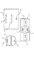
次に、図1~図4を参照して、本発明の第1の実施形態である座標入力装置について説明する。第1の実施形態の座標入力装置1は、タッチパッド2と、コントローラ3とを備えており、ディスプレイ4にタッチパッド2による操作の結果が表示されるように構成されている。
Next, the coordinate input device according to the first embodiment of the present invention will be described with reference to FIGS. The coordinate input device 1 according to the first embodiment includes a touch pad 2 and a controller 3, and is configured to display a result of an operation with the touch pad 2 on a display 4.
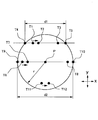
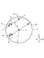
タッチパッド2は、本発明における操作検知部に相当し、例えば、自動車の運転席周りに設けられ、カーナビゲーションシステムやカーオーディオ、或いはカーエアコン等の操作を行うものに利用される。タッチパッド2の形状は、図2に示すように、中心点Pを基準点とする半径rの円となっている。タッチパッド2の外周円は、図2における左右方向をx方向、上下方向をy方向として、式「x2+y2=r2」で表される。
The touch pad 2 corresponds to an operation detection unit in the present invention, and is provided, for example, around a driver's seat of an automobile and used for operations such as a car navigation system, a car audio, or a car air conditioner. The shape of the touch pad 2 is a circle having a radius r with the center point P as a reference point, as shown in FIG. The outer circumferential circle of the touch pad 2 is represented by the expression “x 2 + y 2 = r 2 ” where the left-right direction in FIG.
また、タッチパッド2は、その表面に静電容量センサ(図示省略)が設けられており、ユーザの指やタッチペン等の操作体が触れることにより変化する静電容量を検出し、操作体の操作を検知している。なお、このタッチパッド2は、静電容量検出式のものに限らず、圧力検出式等のものを用いてもよい。
The touch pad 2 is provided with a capacitance sensor (not shown) on the surface thereof, detects the capacitance that changes when an operation body such as a user's finger or a touch pen touches, and operates the operation body. Is detected. The touch pad 2 is not limited to a capacitance detection type but may be a pressure detection type.
コントローラ3は、CPU(中央演算処理装置)、メモリ、或いはインターフェース等の電子デバイスから構成され、その機能的構成として、タッチパッド2から送信されるデータが入力される入力部5と、入力されたデータの各種処理を行う演算部6と、各種データの記憶を行う記憶部7と、各種データが出力される出力部8とを備えている。
The controller 3 is composed of an electronic device such as a CPU (Central Processing Unit), a memory, or an interface, and as its functional configuration, an input unit 5 to which data transmitted from the touchpad 2 is input and an input unit 5 are input. A calculation unit 6 that performs various types of data processing, a storage unit 7 that stores various types of data, and an output unit 8 that outputs various types of data are provided.
演算部6では、単位時間毎(例えば0.01秒毎)にタッチパッド2から送信される信号を受信し、タッチパッド2になされた操作の座標、操作継続時間、移動方向、或いは移動距離の長さ等から操作の種類を判別する。タッチパッド2になされる操作は、タップ操作(指で1回たたく操作)、ダブルタップ操作(指で2回たたく操作)、ドラッグ操作(アイコン等を移動させる操作)、スワイプ操作(軽くはらう操作)、フリック操作(アイコン等をなぞる操作)、ピンチイン操作(2本指でつまんで狭める操作)、ピンチアウト操作(2本指で広げる操作)、ホールド操作(指を保持する操作)等である。
The calculation unit 6 receives a signal transmitted from the touch pad 2 every unit time (for example, every 0.01 seconds), and calculates the coordinates of the operation performed on the touch pad 2, the operation duration, the moving direction, or the moving distance. The type of operation is determined from the length or the like. The operations performed on the touch pad 2 are a tap operation (tapping with a finger once), a double tap operation (tapping with a finger twice), a drag operation (operation to move an icon, etc.), and a swipe operation (light tapping operation). , Flick operation (operation that traces an icon or the like), pinch-in operation (operation that pinches and narrows with two fingers), pinch-out operation (operation that spreads with two fingers), hold operation (operation that holds a finger), and the like.
ディスプレイ4は、例えば、カーナビゲーションシステム用のディスプレイに利用され、カーナビゲーション情報の他、カーオーディオ、或いはカーエアコンの操作情報等が表示される。また、ディスプレイ4は、車両のフロントガラスに反射させて表示させるタイプのディスプレイでもよく、メーターパネル内に設けられるディスプレイであってもよい。
The display 4 is used, for example, as a display for a car navigation system, and displays car audio information, operation information of a car air conditioner, etc. in addition to car navigation information. Further, the display 4 may be a type of display that is reflected on the windshield of the vehicle and may be a display provided in the meter panel.
記憶部7は、RAMやROM等の記憶媒体で構成され、入力部5から入力されるデータ、及び演算部6において演算に利用されるデータが記憶される。また、記憶部7には、本発明の座標入力装置1を作動させるためのプログラムも記憶されている。
The storage unit 7 is configured by a storage medium such as a RAM or a ROM, and stores data input from the input unit 5 and data used for calculation in the calculation unit 6. The storage unit 7 also stores a program for operating the coordinate input device 1 of the present invention.
次に、第1の実施形態の座標入力装置1における作動について説明する。図1は、ユーザがタッチパッド2の表面をドラッグした際の指の動きと、その指の操作がディスプレイ4に表示された際の動きを示している。図1におけるV1はタッチパッド2の外周付近をドラッグしたときの入力ベクトルを示しており、V2はタッチパッド2の中心付近をドラッグしたときの入力ベクトルを示している。また、V3はタッチパッド2の外周付近をゆっくりドラッグしたときの入力ベクトルを示している。
Next, the operation of the coordinate input device 1 of the first embodiment will be described. FIG. 1 shows the movement of a finger when the user drags the surface of the touch pad 2 and the movement when the operation of the finger is displayed on the display 4. V1 in FIG. 1 indicates an input vector when the vicinity of the outer periphery of the touch pad 2 is dragged, and V2 indicates an input vector when the vicinity of the center of the touch pad 2 is dragged. V3 indicates an input vector when the vicinity of the outer periphery of the touch pad 2 is slowly dragged.
ディスプレイ4においては、V4がユーザによって入力ベクトルV1の操作がなされたときの表示上の動きを示しており、V5は入力ベクトルV2の操作がなされたときの表示上の動きを示している。また、V6は入力ベクトルV3の操作がなされたときの表示上の動きを示している。
On the display 4, V4 shows the movement on the display when the input vector V1 is operated by the user, and V5 shows the movement on the display when the input vector V2 is operated. V6 indicates the movement on the display when the input vector V3 is operated.
図1に示すように、第1の実施形態の座標入力装置1では、コントローラ3の演算部6によって、入力ベクトルV1でタッチパッド2の外周付近において短い距離でドラッグされた結果である出力ベクトルV4と、入力ベクトルV2でタッチパッド2の中心付近において長い距離でドラッグされた結果である出力ベクトルV5が同等の長さとなるように設定されている。
As shown in FIG. 1, in the coordinate input device 1 of the first embodiment, an output vector V4 that is a result of being dragged at a short distance near the outer periphery of the touchpad 2 by the calculation unit 6 of the controller 3 with the input vector V1. Then, the output vector V5, which is the result of dragging a long distance near the center of the touchpad 2 with the input vector V2, is set to have the same length.
入力ベクトルV1は、タッチパッド2の外周付近をユーザが指でドラッグしたものであるが、タッチパッド2の外周付近は中心付近に比べて指を動かせる長さが短い。図2の点T1はタッチパッド2に指がタッチした始点であり、点T3が終点となる。
The input vector V1 is obtained by the user dragging the vicinity of the outer periphery of the touch pad 2 with a finger, but the vicinity of the outer periphery of the touch pad 2 is shorter in length than the vicinity of the center. A point T1 in FIG. 2 is a starting point where the finger touches the touch pad 2, and a point T3 is an end point.
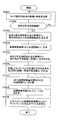
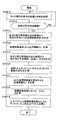
ユーザが指でタッチパッド2の始点T1にタッチすると、演算部6ではタッチパッド2から送信されるデータによって始点T1の座標と、タッチされた時刻を取得する(STEP1)。ユーザが指を終点T3の方向にドラッグすると、演算部6では単位時間毎にタッチパッド2における指の位置を取得しているので、単位時間毎に指の座標が演算部6に入力される。
When the user touches the start point T1 of the touch pad 2 with a finger, the calculation unit 6 acquires the coordinates of the start point T1 and the touched time based on the data transmitted from the touch pad 2 (STEP 1). When the user drags the finger in the direction of the end point T3, the calculation unit 6 acquires the position of the finger on the touch pad 2 every unit time, and thus the finger coordinates are input to the calculation unit 6 every unit time.
図2における点T2は、タッチパッド2に指がタッチした始点T1から単位時間後に検知された指の位置である。本実施形態では、タッチパッド2への入力操作が、この単位時間のn倍(例えば2倍)継続した場合に(STEP2においてYES)、入力操作による入力ベクトルに対して補正処理を行い、ディスプレイ4における出力ベクトルを決定する。
The point T2 in FIG. 2 is the position of the finger detected after a unit time from the start point T1 at which the finger touched the touch pad 2. In this embodiment, when the input operation to the touch pad 2 continues n times (for example, twice) of the unit time (YES in STEP 2), the correction process is performed on the input vector by the input operation, and the display 4 Determine the output vector at.
図2において、タッチパッド2にユーザが指で始点T1から終点T3までドラッグ操作を行うと、このドラッグ操作は単位時間のn倍以上の操作であるため、演算部6において以下の処理が行われる。
In FIG. 2, when the user performs a drag operation on the touch pad 2 with a finger from the start point T1 to the end point T3, the drag operation is an operation of n times or more of the unit time, and thus the following processing is performed in the calculation unit 6. .
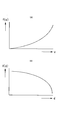
まず、始点T1の座標(x1,y1)と時刻が取得され、単位時間後の点T2における座標(x2,y2)が取得される。次に、演算部6において、これらの情報から指の移動速度vを算出し(STEP3)、伝達関数f(v)を演算する(STEP4)。この伝達関数f(v)は、例えば、感覚量は刺激量の対数に比例するとするウェーバー・フェヒナーの法則を利用して、人間の感覚に合うように非線形に増加させる関数を用いる(式1)。図4(A)は、この式1の関数のグラフを示しており、縦軸は増加させる倍数であり、横軸は指の速さである。
First, the coordinates (x 1 , y 1 ) and time of the start point T1 are acquired, and the coordinates (x 2 , y 2 ) at the point T2 after the unit time are acquired. Next, the calculation unit 6 calculates the moving speed v of the finger from these pieces of information (STEP 3), and calculates the transfer function f (v) (STEP 4). As this transfer function f (v), for example, a function that increases nonlinearly so as to match the human sense by using Weber-Fechner's law that the sense amount is proportional to the logarithm of the stimulus amount (Equation 1). . FIG. 4A shows a graph of the function of Equation 1, where the vertical axis is a multiple to be increased and the horizontal axis is the finger speed.

また、タッチパッド2の外周円は、式「x2+y2=r2」で表される。ここで、直線Lを表す式とタッチパッド2の外周円を示す式を用いて、始点T1から点T2までの移動方向から求められる直線Lと、タッチパッド2の外周円との2つの交点の座標T4,T5を計算し、このT4,T5間の距離d1が求められる(STEP6)。この距離は、始点T1を通る直線Lの方向において、指がタッチパッド2上を移動可能な移動可能距離となる。
Further, the outer peripheral circle of the touch pad 2 is represented by an expression “x 2 + y 2 = r 2 ”. Here, using the equation representing the straight line L and the equation representing the outer circumference circle of the touch pad 2, two intersection points of the straight line L obtained from the moving direction from the start point T1 to the point T2 and the outer circumference circle of the touch pad 2 are calculated. Coordinates T4 and T5 are calculated, and a distance d1 between T4 and T5 is obtained (STEP 6). This distance is a movable distance in which the finger can move on the touch pad 2 in the direction of the straight line L passing through the start point T1.
次に、2点間の距離d1を基礎として、座標移動量を増加させる伝達関数f(d)を計算する(STEP7)。この伝達関数f(d)は、dが小さいほど、f(d)が大きくなる関数を用いる。例えば、タッチパッドの中心Pから直線Lに引いた垂線の長さpに比例する伝達関数f(p)を距離dで表す伝達関数f(d)は、図4(B)のようなグラフで表される。(尚、伝達関数f(p)は、後述する。)T4,T5間の距離d1は、タッチパッド2の直径2rよりも短いので、伝達関数f(d)は、1よりも大きな値となる。
Next, based on the distance d1 between the two points, a transfer function f (d) for increasing the coordinate movement amount is calculated (STEP 7). As the transfer function f (d), a function is used in which f (d) increases as d decreases. For example, the transfer function f (d), which represents the transfer function f (p) proportional to the length p of the perpendicular drawn from the center P of the touchpad to the straight line L, as a distance d, is a graph as shown in FIG. expressed. (The transfer function f (p) will be described later.) Since the distance d1 between T4 and T5 is shorter than the diameter 2r of the touch pad 2, the transfer function f (d) is a value larger than 1. .
次に、演算部6において、入力ベクトルV1を出力ベクトルV4に変換する際の座標移動係数ACLを求める(STEP8)。この座標移動係数は、「ACL=f(d)×f(v)」で求められる。そして、入力ベクトルV1と座標移動係数ACLから、出力ベクトルV4の座標を求める(STEP9)。
Next, the calculation unit 6 obtains a coordinate movement coefficient ACL for converting the input vector V1 into the output vector V4 (STEP 8). This coordinate movement coefficient is obtained by “ACL = f (d) × f (v)”. Then, the coordinates of the output vector V4 are obtained from the input vector V1 and the coordinate movement coefficient ACL (STEP 9).
入力ベクトルV1は、始点T1(x1,y1)から終点T3(x3,y3)までの長さと方向で求められる。この入力ベクトルV1に座標移動係数ACLを乗算して出力ベクトルV4の座標を求める。このように、演算部6で求められた出力ベクトルV4の座標は、出力部8を介してディスプレイ4に送信され、ディスプレイ4上において、出力ベクトルV4の操作の軌跡が表示される。
The input vector V1 is obtained by the length and direction from the start point T1 (x 1 , y 1 ) to the end point T3 (x 3 , y 3 ). The input vector V1 is multiplied by the coordinate movement coefficient ACL to obtain the coordinates of the output vector V4. As described above, the coordinates of the output vector V4 obtained by the calculation unit 6 are transmitted to the display 4 via the output unit 8, and the operation locus of the output vector V4 is displayed on the display 4.
上記操作は、入力ベクトルV2においても同様に行われる。入力ベクトルV2では、ユーザによる操作がタッチパッド2の中心点Pを通る位置でドラッグ操作が行われる。まず、始点T6の座標(x6,y6)が取得され、単位時間後の点T7における座標(x7,y7)が取得される。次に、始点T6から単位時間後の点T7への指の移動動作を元に直線Lを算出する。次に、直線Lとタッチパッド2の外周円との2つの交点T9,T10の座標を計算し、交点間の距離d2(移動可能距離)を求める。
The above operation is similarly performed on the input vector V2. In the input vector V2, the drag operation is performed at a position where the operation by the user passes through the center point P of the touch pad 2. First, the coordinates (x 6 , y 6 ) of the start point T6 are acquired, and the coordinates (x 7 , y 7 ) at the point T7 after the unit time are acquired. Next, a straight line L is calculated based on the movement operation of the finger from the start point T6 to the point T7 after unit time. Next, the coordinates of two intersections T9 and T10 between the straight line L and the outer circumference of the touch pad 2 are calculated, and a distance d2 (movable distance) between the intersections is obtained.
次に、2点間の距離d2を基礎として、座標移動量を増加させる伝達関数f(d)を計算する。入力ベクトルV2では、この距離d2がタッチパッド2における最大の位置となっている。このため、伝達関数f(d)の出力は1となる。
Next, based on the distance d2 between the two points, a transfer function f (d) that increases the coordinate movement amount is calculated. In the input vector V2, this distance d2 is the maximum position on the touch pad 2. For this reason, the output of the transfer function f (d) is 1.
次に、2点間の指の速度vを基礎として、伝達関数f(v)を求める。その後、演算部6において、入力ベクトルV2(始点T6~終点T8)を出力ベクトルV5に変換する際の座標移動係数ACLを求める。この座標移動係数は、「ACL=f(d)×f(v)」で求められる。そして、入力ベクトルV2と座標移動係数ACLから、出力ベクトルV5の座標を求める。
Next, the transfer function f (v) is obtained based on the finger speed v between the two points. Thereafter, the calculation unit 6 obtains a coordinate movement coefficient ACL for converting the input vector V2 (start point T6 to end point T8) into the output vector V5. This coordinate movement coefficient is obtained by “ACL = f (d) × f (v)”. Then, the coordinates of the output vector V5 are obtained from the input vector V2 and the coordinate movement coefficient ACL.
入力ベクトルV2は、伝達関数f(d)の出力が1となっているため、座標移動係数ACLは伝達関数f(v)と同じ値になる。図1においては、伝達関数f(v)が1となる状態を示しており、座標移動係数ACLも1となる。従って、ユーザが指で入力ベクトルV2の入力を行うことにより、ディスプレイ4に入力ベクトルV2と同様の長さの出力ベクトルV5が表示される。
Since the output of the transfer function f (d) is 1 in the input vector V2, the coordinate movement coefficient ACL has the same value as the transfer function f (v). FIG. 1 shows a state where the transfer function f (v) is 1, and the coordinate movement coefficient ACL is also 1. Accordingly, when the user inputs the input vector V2 with a finger, the output vector V5 having the same length as the input vector V2 is displayed on the display 4.
一方、図1における入力ベクトルV3は、ユーザが指をゆっくり動かした際の入力ベクトルである。例えば、ユーザがタッチ操作で何らかの微調整を行う場合、指をゆっくり動かす操作となる。図2において、始点T11から終点T12まで指をゆっくり動かすと、タッチパッド2で検出される操作速度が遅くなるため、伝達関数f(v)の値が小さくなる。なお、指の動きがゆっくりか否かを決める閾値は、適用される製品に応じて決めることができる。
On the other hand, the input vector V3 in FIG. 1 is an input vector when the user slowly moves the finger. For example, when the user performs some fine adjustment by a touch operation, it is an operation of slowly moving a finger. In FIG. 2, when the finger is slowly moved from the start point T11 to the end point T12, the operation speed detected by the touch pad 2 becomes slow, and the value of the transfer function f (v) becomes small. Note that the threshold for determining whether or not the finger moves slowly can be determined according to the product to be applied.
よって、演算部6で求められる座標移動係数ACLの値も小さくなる。このため、入力ベクトルV3に対する出力ベクトルV6の増加倍率も小さくなるので、出力ベクトルV6は入力ベクトルV3とほぼ同等の長さとなる。
Therefore, the value of the coordinate movement coefficient ACL obtained by the calculation unit 6 is also reduced. For this reason, since the increase rate of the output vector V6 with respect to the input vector V3 is also reduced, the output vector V6 has substantially the same length as the input vector V3.
第1の実施形態の座標入力装置1では、このように、ユーザの指の軌跡からタッチパッド2内を移動可能な移動可能距離を算出し、その移動可能距離と指の操作の速度を用いて入力ベクトルV1~V3を出力ベクトルV4~V6に変換する演算を行っている。
In the coordinate input device 1 according to the first embodiment, as described above, the movable distance that can be moved in the touch pad 2 is calculated from the locus of the user's finger, and the movable distance and the operation speed of the finger are used. An operation for converting the input vectors V1 to V3 into the output vectors V4 to V6 is performed.
これにより、タッチパッド2の形状がディスプレイ4とは異なる形状となる場合であっても、ユーザの操作感覚に近い結果がディスプレイ4上で得られることになる。つまり、移動可能距離が短いほど入力ベクトルに対する出力ベクトルの大きさを大きくすることで、端の近くを触った場合にも、出力ベクトルの長さを充分に大きくすることができる。
Thereby, even if the shape of the touch pad 2 is different from that of the display 4, a result close to the user's sense of operation can be obtained on the display 4. That is, as the movable distance is shorter, the size of the output vector with respect to the input vector is increased, so that the length of the output vector can be sufficiently increased even when the end is touched.
よって、本発明によれば、ユーザに違和感を与えることなくタッチパッド2の形状を適用される機器に応じて変形させることが可能となる。タッチパッド2の形状としては、楕円形、角丸長円形等の丸みのある形状にすることもでき、菱形や五角形、その他の多角形等の角張った形状とすることも可能となる。
Therefore, according to the present invention, it is possible to change the shape of the touch pad 2 according to the device to which the touch pad 2 is applied without giving the user a sense of incongruity. The shape of the touch pad 2 may be a round shape such as an ellipse or a rounded oval, or may be a square shape such as a rhombus, a pentagon, or another polygon.
次に、第2の実施形態である座標入力装置1aについて、図5~図10を参照して説明する。第2の実施形態の座標入力装置1aは、ハードウエア構成は第1の実施形態と同様であり、演算部6における入力ベクトルV7,V8から出力ベクトルV9,V10を求める演算が第1の実施形態と異なっている。なお、第2の実施形態において、第1の実施形態と同様の構成の場合、同一の符号を付して詳細な説明を省略する。
Next, a coordinate input device 1a according to the second embodiment will be described with reference to FIGS. The coordinate input device 1a of the second embodiment has the same hardware configuration as that of the first embodiment, and the calculation for obtaining the output vectors V9 and V10 from the input vectors V7 and V8 in the calculation unit 6 is the first embodiment. Is different. Note that, in the second embodiment, in the case of a configuration similar to that of the first embodiment, the same reference numerals are given and detailed description thereof is omitted.
第2の実施形態では、図5に示すように、タッチパッド2の基準点となる中心点Pからユーザの指が操作したベクトルまでの距離pを算出し、その距離pに応じて座標移動係数ACLを求める。図5の点T1はタッチパッド2に指がタッチした始点であり、点T3が終点となる。
In the second embodiment, as shown in FIG. 5, a distance p from a center point P as a reference point of the touch pad 2 to a vector operated by the user's finger is calculated, and a coordinate movement coefficient is calculated according to the distance p. Find the ACL. A point T1 in FIG. 5 is a starting point where the finger touches the touch pad 2, and a point T3 is an end point.
ユーザが指でタッチパッド2の始点T1にタッチすると、演算部6ではタッチパッド2から送信されるデータによって始点T1の座標と、タッチされた時刻を取得する(STEP11)。ユーザが指を終点T3の方向にドラッグすると、演算部6では単位時間毎にタッチパッド2における指の位置を取得しているので、単位時間毎に指の座標が演算部6に入力される。
When the user touches the start point T1 of the touch pad 2 with a finger, the calculation unit 6 acquires the coordinates of the start point T1 and the touched time based on the data transmitted from the touch pad 2 (STEP 11). When the user drags the finger in the direction of the end point T3, the calculation unit 6 acquires the position of the finger on the touch pad 2 every unit time, and thus the finger coordinates are input to the calculation unit 6 every unit time.
図5における点T2は、タッチパッド2に指がタッチした始点T1から単位時間後に検知された指の位置である。演算部6では、始点T1の座標(x1,y1)が取得され、単位時間後の点T2における座標(x2,y2)が取得される。タッチパッド2への入力操作が、この単位時間のn倍(例えば2倍)継続した場合(STEP12においてYES)、演算部6において、これらの情報から指の移動速度vを算出し(STEP13)、伝達関数f(v)を演算する(STEP14)。
A point T2 in FIG. 5 is the position of the finger detected after a unit time from the start point T1 at which the finger touches the touch pad 2. In the calculation unit 6, the coordinates (x 1 , y 1 ) of the start point T1 are acquired, and the coordinates (x 2 , y 2 ) at the point T2 after the unit time are acquired. When the input operation to the touch pad 2 continues n times (for example, twice) of the unit time (YES in STEP 12), the calculation unit 6 calculates the finger moving speed v from these pieces of information (STEP 13). The transfer function f (v) is calculated (STEP 14).
本実施形態では、伝達関数f(v)は、上記式1ではなく、図7のように傾きを徐々に増加させた1次関数を接続したものとしている。このような伝達関数f(v)によっても、人間の操作感覚に合うように増加率を決定することができる。
In this embodiment, it is assumed that the transfer function f (v) is not the above equation 1 but a linear function with a gradually increasing slope as shown in FIG. Also by such a transfer function f (v), the increase rate can be determined so as to match the human operation feeling.
次に、演算部6では、これらの座標から指の移動方向の一次関数である直線L「ax+by+c=0」の係数a,b,cを求める(STEP15)。次に、直線Lからタッチパッド2の中心点Pの座標「x0,y0」までの垂線pの長さを求める(STEP16)。
垂線pの長さは以下の式2で求められる。 Next, thecalculation unit 6 obtains coefficients a, b, and c of the straight line L “ax + by + c = 0”, which is a linear function of the finger movement direction, from these coordinates (STEP 15). Next, the length of the perpendicular p from the straight line L to the coordinates “x 0 , y 0 ” of the center point P of the touch pad 2 is obtained (STEP 16).
The length of the perpendicular p is obtained by thefollowing equation 2.
垂線pの長さは以下の式2で求められる。 Next, the
The length of the perpendicular p is obtained by the

その後、演算部6において、入力ベクトルV7を出力ベクトルV9に変換する際の座標移動係数ACLを求める(STEP18)。この座標移動係数は、「ACL=f(v)×f(p)」で求められる。そして、入力ベクトルV7と座標移動係数ACLから、出力ベクトルV9の座標を求める(STEP19)。
Thereafter, the calculation unit 6 obtains a coordinate movement coefficient ACL for converting the input vector V7 into the output vector V9 (STEP 18). This coordinate movement coefficient is obtained by “ACL = f (v) × f (p)”. Then, the coordinates of the output vector V9 are obtained from the input vector V7 and the coordinate movement coefficient ACL (STEP 19).
入力ベクトルV7は、始点T1(x1,y1)から終点T3(x3,y3)までの長さと方向で求められる。この入力ベクトルV7に座標移動係数ACLを乗算して出力ベクトルV9の座標を求める。このように、演算部6で求められた出力ベクトルV9の座標は、出力部8を介してディスプレイ4に送信され、ディスプレイ4上において、出力ベクトルV9の操作の軌跡が表示される。
The input vector V7 is obtained from the length and direction from the start point T1 (x 1 , y 1 ) to the end point T3 (x 3 , y 3 ). The input vector V7 is multiplied by the coordinate movement coefficient ACL to obtain the coordinates of the output vector V9. As described above, the coordinates of the output vector V9 obtained by the calculation unit 6 are transmitted to the display 4 via the output unit 8, and an operation locus of the output vector V9 is displayed on the display 4.
図8は、タッチパッド2における指の軌跡と、ディスプレイ4における表示の軌跡を表す図である。出力ベクトルV9がユーザによってタッチパッド2の外周付近でのタッチ操作(入力ベクトルV7)がなされたときの表示上の動きを示しており、出力ベクトルV10はタッチパッド2の中心付近でのタッチ操作(入力ベクトルV8)がなされたときの表示上の動きを示している。
FIG. 8 is a diagram illustrating a finger trajectory on the touch pad 2 and a display trajectory on the display 4. The output vector V9 shows the movement on the display when the user performs a touch operation (input vector V7) near the outer periphery of the touch pad 2, and the output vector V10 is a touch operation (near the center of the touch pad 2). The movement on the display when the input vector V8) is made is shown.
図8に示すように、第2の実施形態の座標入力装置1aにおいても、コントローラ3の演算部6によって、タッチパッド2の外周付近において短い距離でドラッグされた結果と、タッチパッド2の中心点P付近において長い距離でドラッグされた結果が同等となるように設定されている。
As shown in FIG. 8, also in the coordinate input device 1 a of the second embodiment, the result of the operation unit 6 of the controller 3 dragging at a short distance near the outer periphery of the touch pad 2 and the center point of the touch pad 2. The result of dragging a long distance in the vicinity of P is set to be equivalent.
ここで、座標移動係数「ACL=f(p)×f(v)」において、pを最小にしたときと、pを最大にしたときの計算結果を図9に示す。図9において、線A1はpを最大に振った際の曲線、線A2はpを最小に振った際の曲線である。
Here, in the coordinate movement coefficient “ACL = f (p) × f (v)”, calculation results when p is minimized and p is maximized are shown in FIG. In FIG. 9, line A1 is a curve when p is maximized, and line A2 is a curve when p is minimized.
このように、タッチパッド2の中心点P付近では、指の操作速度が上がるにつれて座標移動係数が上昇しているが、上昇の割合は小さい。一方で、タッチパッド2の外周円付近では、指の操作速度の上昇に合わせて、座標移動係数の上昇割合が増加している。
Thus, in the vicinity of the center point P of the touch pad 2, the coordinate movement coefficient increases as the finger operation speed increases, but the rate of increase is small. On the other hand, in the vicinity of the outer peripheral circle of the touch pad 2, the increase rate of the coordinate movement coefficient increases with the increase of the finger operation speed.
次に、第2の実施形態の座標入力装置1aの変形例について、図10を参照して説明する。この変形例においては、演算部6において、垂線の長さpから座標移動量を増加させる増加倍率である伝達関数f(p)を計算する際の手法が、上記第2の実施形態と相違している。
Next, a modification of the coordinate input device 1a of the second embodiment will be described with reference to FIG. In this modification, the method for calculating the transfer function f (p), which is an increase magnification for increasing the coordinate movement amount from the length p of the perpendicular line, in the calculation unit 6 is different from that in the second embodiment. ing.
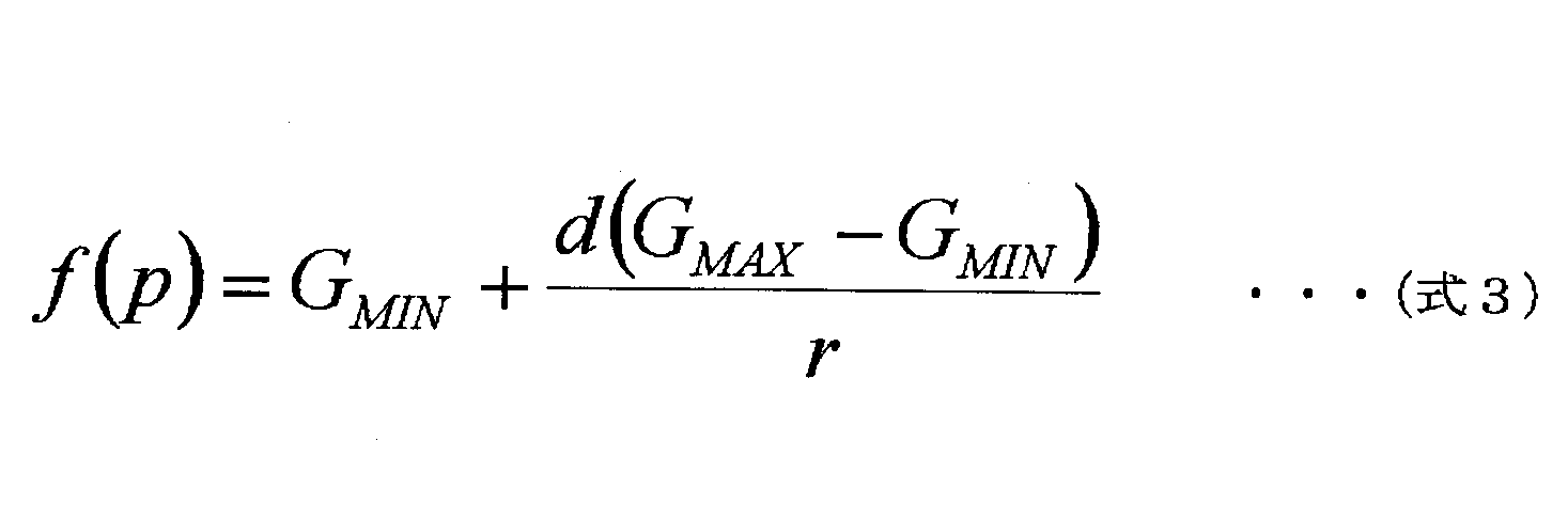
当該変形例においては、伝達関数f(p)を、式3ではなく以下の式4で求める。この式4では、図10に示すように、タッチパッド2の中心点Pから距離eまでは増加倍率を0(GMIN)として、距離eから外周円までの増加倍率を徐々に増やし、タッチパッド2の外周円の位置で最大(GMAX)となるようにしている。
In this modification, the transfer function f (p) is obtained by the following expression 4 instead of expression 3. In this equation 4, as shown in FIG. 10, the increase magnification from the center point P of the touch pad 2 to the distance e is set to 0 (G MIN ), and the increase magnification from the distance e to the outer circle is gradually increased. 2 (G MAX ) at the position of the outer circumference circle.

なお、上記実施形態においては、伝達関数その他の計算式の具体例を示しているが、本発明の座標入力装置においては、上記具体例に限定することなく、適宜好適な計算式を選択して用いることができる。また、本発明の座標入力装置は、自動車に用いる場合の他、パーソナルコンピュータ等の電子機器や、冷蔵庫、レンジ等の家電にも広く適用することができる。
In the above embodiment, specific examples of transfer functions and other calculation formulas are shown. However, in the coordinate input device of the present invention, a suitable calculation formula is appropriately selected without being limited to the above specific examples. Can be used. The coordinate input device of the present invention can be widely applied to electronic devices such as a personal computer, and home appliances such as a refrigerator and a range, as well as when used in an automobile.
本願は、日本特許庁に2017年1月17日に出願された基礎出願2017-005865号の優先権を主張するものであり、その全内容を参照によりここに援用する。
This application claims priority of the basic application 2017-005865 filed on January 17, 2017 with the Japan Patent Office, the entire contents of which are incorporated herein by reference.
1,1a…座標入力装置
2…タッチパッド(操作検知部)
3…コントローラ
4…ディスプレイ
5…入力部
6…演算部
7…記憶部
8…出力部
V1,V2,V3,V7,V8…入力ベクトル
V4,V5,V6,V9,V10…出力ベクトル DESCRIPTION OF SYMBOLS 1, 1a ... Coordinate input device 2 ... Touch pad (operation detection part)
DESCRIPTION OFSYMBOLS 3 ... Controller 4 ... Display 5 ... Input part 6 ... Operation part 7 ... Memory | storage part 8 ... Output part V1, V2, V3, V7, V8 ... Input vector V4, V5, V6, V9, V10 ... Output vector
2…タッチパッド(操作検知部)
3…コントローラ
4…ディスプレイ
5…入力部
6…演算部
7…記憶部
8…出力部
V1,V2,V3,V7,V8…入力ベクトル
V4,V5,V6,V9,V10…出力ベクトル DESCRIPTION OF
DESCRIPTION OF
Claims (4)
- 操作体による入力操作を検知する操作検知部と、入力操作の結果を演算して演算結果を算出する演算部とを備えた座標入力装置において、前記演算部は、前記操作検知部への入力操作が所定時間継続した場合、前記操作検知部の第1の時刻における第1の位置と、前記第1の時刻後の第2の時刻に検出された第2の位置の座標を取得して前記第1の位置から前記第2の位置に向かう入力ベクトルを演算し、前記第1の位置と前記第2の位置とを結ぶ線上にある前記操作検知部の端から端までの距離である移動可能距離を演算し、前記移動可能距離が短いほど、前記入力ベクトルの値を補正する補正値を大きくして、出力ベクトルを算出することを特徴とする座標入力装置。 In a coordinate input apparatus including an operation detection unit that detects an input operation by an operating body and a calculation unit that calculates a result of the input operation and calculates a calculation result, the calculation unit is configured to input an operation to the operation detection unit. Is acquired for a predetermined time, the coordinates of the first position at the first time of the operation detection unit and the second position detected at the second time after the first time are acquired and the first position is acquired. An input vector from the position 1 to the second position is calculated, and a movable distance that is a distance from end to end of the operation detection unit on a line connecting the first position and the second position The coordinate input device calculates the output vector by increasing the correction value for correcting the value of the input vector as the movable distance is shorter.
- 操作体による入力操作を検知する操作検知部と、入力操作の結果を演算して演算結果を算出する演算部とを備えた座標入力装置において、前記演算部は、前記操作検知部への入力操作が所定時間継続した場合、前記操作検知部の第1の時刻における第1の位置と、前記第1の時刻後の第2の時刻に検出された第2の位置の座標を取得して前記第1の位置から前記第2の位置に向かう入力ベクトルを演算し、前記第1の位置と前記第2の位置とを結ぶ線から前記操作検知部の基準点までの垂線の長さを求め、前記垂線の長さが長いほど、前記入力ベクトルの値を補正する補正値を大きくして、出力ベクトルを算出することを特徴とする座標入力装置。 In a coordinate input apparatus including an operation detection unit that detects an input operation by an operating body and a calculation unit that calculates a result of the input operation and calculates a calculation result, the calculation unit is configured to input an operation to the operation detection unit. Is acquired for a predetermined time, the coordinates of the first position at the first time of the operation detection unit and the second position detected at the second time after the first time are acquired and the first position is acquired. Calculating an input vector from the position 1 to the second position, obtaining a length of a perpendicular from a line connecting the first position and the second position to a reference point of the operation detection unit, A coordinate input apparatus that calculates an output vector by increasing a correction value for correcting the value of the input vector as the length of the perpendicular is longer.
- 前記操作検知部の形状が、円形、楕円形、又は角丸長円形であることを特徴とする請求項1又は2に記載の座標入力装置。 The coordinate input device according to claim 1 or 2, wherein the shape of the operation detection unit is a circle, an ellipse, or a rounded oval.
- 前記演算部は、前記第1の時刻から前記第2の時刻までの間の時間と、前記第1の位置の座標から前記第2の位置の座標への移動量から前記操作体の移動速度を算出し、前記移動速度が所定の閾値以下のときは、前記補正値を減少させることを特徴とする請求項1~3のいずれかに記載の座標入力装置。 The calculation unit calculates a moving speed of the operating body from a time from the first time to the second time and a moving amount from the coordinates of the first position to the coordinates of the second position. The coordinate input device according to any one of claims 1 to 3, wherein the coordinate value is calculated and decreased when the moving speed is equal to or less than a predetermined threshold value.
Priority Applications (3)
| Application Number | Priority Date | Filing Date | Title |
|---|---|---|---|
| EP17892459.3A EP3572917B1 (en) | 2017-01-17 | 2017-12-11 | Coordinate input apparatus |
| JP2018563212A JP6724172B2 (en) | 2017-01-17 | 2017-12-11 | Coordinate input device |
| US16/504,489 US10802650B2 (en) | 2017-01-17 | 2019-07-08 | Coordinate input device |
Applications Claiming Priority (2)
| Application Number | Priority Date | Filing Date | Title |
|---|---|---|---|
| JP2017005865 | 2017-01-17 | ||
| JP2017-005865 | 2017-01-17 |
Related Child Applications (1)
| Application Number | Title | Priority Date | Filing Date |
|---|---|---|---|
| US16/504,489 Continuation US10802650B2 (en) | 2017-01-17 | 2019-07-08 | Coordinate input device |
Publications (1)
| Publication Number | Publication Date |
|---|---|
| WO2018135183A1 true WO2018135183A1 (en) | 2018-07-26 |
Family
ID=62907923
Family Applications (1)
| Application Number | Title | Priority Date | Filing Date |
|---|---|---|---|
| PCT/JP2017/044409 WO2018135183A1 (en) | 2017-01-17 | 2017-12-11 | Coordinate input apparatus |
Country Status (4)
| Country | Link |
|---|---|
| US (1) | US10802650B2 (en) |
| EP (1) | EP3572917B1 (en) |
| JP (1) | JP6724172B2 (en) |
| WO (1) | WO2018135183A1 (en) |
Cited By (1)
| Publication number | Priority date | Publication date | Assignee | Title |
|---|---|---|---|---|
| US10838555B2 (en) | 2019-02-12 | 2020-11-17 | Alps Alpine Co., Ltd. | Position outputting device |
Citations (8)
| Publication number | Priority date | Publication date | Assignee | Title |
|---|---|---|---|---|
| JP2002244809A (en) * | 2001-02-13 | 2002-08-30 | Kenji Kishimoto | Method and device for freely changing moving speed of pointer, and minimization of touch pad |
| JP2006268665A (en) * | 2005-03-25 | 2006-10-05 | Sharp Corp | Cursor movement device, cursor movement method, program and recording medium |
| JP2011048525A (en) * | 2009-08-26 | 2011-03-10 | Sony Corp | Apparatus and method for processing information, and computer program |
| US20130120129A1 (en) * | 2011-11-11 | 2013-05-16 | Volkswagen Ag | Gearshift knob and method for operating a vehicle |
| JP2014186555A (en) | 2013-03-22 | 2014-10-02 | Sharp Corp | Information processing device and information processing method |
| JP2015535117A (en) * | 2012-11-19 | 2015-12-07 | アイティヴァス カンパニー リミテッドItvers Co.,Ltd. | Touch pad input device |
| JP2016103214A (en) | 2014-11-28 | 2016-06-02 | シャープ株式会社 | Touch panel device and image display method |
| JP2017005865A (en) | 2015-06-10 | 2017-01-05 | トヨタ自動車株式会社 | Non-contact power transmission device and power transmission system |
Family Cites Families (17)
| Publication number | Priority date | Publication date | Assignee | Title |
|---|---|---|---|---|
| US4736191A (en) * | 1985-08-02 | 1988-04-05 | Karl E. Matzke | Touch activated control method and apparatus |
| US7274355B2 (en) * | 2003-04-25 | 2007-09-25 | Oqo, Inc. | Blended transfer function for computer pointing devices |
| JP2006268663A (en) * | 2005-03-25 | 2006-10-05 | Sharp Corp | Cursor movement control device, cursor movement control method, program and recording medium |
| US8743060B2 (en) * | 2006-07-06 | 2014-06-03 | Apple Inc. | Mutual capacitance touch sensing device |
| JP5477833B2 (en) * | 2007-01-15 | 2014-04-23 | カシオ計算機株式会社 | Pointing device, pointing method and program |
| KR101476088B1 (en) * | 2008-12-18 | 2014-12-23 | 닛본 덴끼 가부시끼가이샤 | Slide bar display control apparatus and slide bar display control method |
| WO2010113397A1 (en) * | 2009-03-31 | 2010-10-07 | 三菱電機株式会社 | Display input device |
| US8466934B2 (en) * | 2009-06-29 | 2013-06-18 | Min Liang Tan | Touchscreen interface |
| JP5552947B2 (en) * | 2010-07-30 | 2014-07-16 | ソニー株式会社 | Information processing apparatus, display control method, and display control program |
| JP5510201B2 (en) * | 2010-08-31 | 2014-06-04 | 日本精機株式会社 | Control device |
| JP5497722B2 (en) * | 2011-10-14 | 2014-05-21 | パナソニック株式会社 | Input device, information terminal, input control method, and input control program |
| JP2014010777A (en) * | 2012-07-02 | 2014-01-20 | Fujitsu Ltd | Display program, display method, and information processing device |
| KR102123061B1 (en) * | 2012-11-27 | 2020-06-16 | 삼성전자주식회사 | Boundary segmentation apparatus and method based on user interaction |
| CN103970278B (en) * | 2013-01-25 | 2017-02-08 | 胡竞韬 | Input method and device for round touch keyboard |
| JP2015032132A (en) * | 2013-08-02 | 2015-02-16 | ブラザー工業株式会社 | Image information processing apparatus and program |
| JP6051183B2 (en) * | 2014-08-19 | 2016-12-27 | 京セラドキュメントソリューションズ株式会社 | Display control apparatus and electronic device |
| KR101681990B1 (en) * | 2015-04-30 | 2016-12-02 | 현대자동차주식회사 | Control apparatus using touch and vehicle comprising the same |
-
2017
- 2017-12-11 JP JP2018563212A patent/JP6724172B2/en active Active
- 2017-12-11 WO PCT/JP2017/044409 patent/WO2018135183A1/en unknown
- 2017-12-11 EP EP17892459.3A patent/EP3572917B1/en active Active
-
2019
- 2019-07-08 US US16/504,489 patent/US10802650B2/en active Active
Patent Citations (8)
| Publication number | Priority date | Publication date | Assignee | Title |
|---|---|---|---|---|
| JP2002244809A (en) * | 2001-02-13 | 2002-08-30 | Kenji Kishimoto | Method and device for freely changing moving speed of pointer, and minimization of touch pad |
| JP2006268665A (en) * | 2005-03-25 | 2006-10-05 | Sharp Corp | Cursor movement device, cursor movement method, program and recording medium |
| JP2011048525A (en) * | 2009-08-26 | 2011-03-10 | Sony Corp | Apparatus and method for processing information, and computer program |
| US20130120129A1 (en) * | 2011-11-11 | 2013-05-16 | Volkswagen Ag | Gearshift knob and method for operating a vehicle |
| JP2015535117A (en) * | 2012-11-19 | 2015-12-07 | アイティヴァス カンパニー リミテッドItvers Co.,Ltd. | Touch pad input device |
| JP2014186555A (en) | 2013-03-22 | 2014-10-02 | Sharp Corp | Information processing device and information processing method |
| JP2016103214A (en) | 2014-11-28 | 2016-06-02 | シャープ株式会社 | Touch panel device and image display method |
| JP2017005865A (en) | 2015-06-10 | 2017-01-05 | トヨタ自動車株式会社 | Non-contact power transmission device and power transmission system |
Non-Patent Citations (1)
| Title |
|---|
| See also references of EP3572917A4 |
Cited By (1)
| Publication number | Priority date | Publication date | Assignee | Title |
|---|---|---|---|---|
| US10838555B2 (en) | 2019-02-12 | 2020-11-17 | Alps Alpine Co., Ltd. | Position outputting device |
Also Published As
| Publication number | Publication date |
|---|---|
| EP3572917A1 (en) | 2019-11-27 |
| US10802650B2 (en) | 2020-10-13 |
| JPWO2018135183A1 (en) | 2019-06-27 |
| JP6724172B2 (en) | 2020-07-15 |
| US20190332242A1 (en) | 2019-10-31 |
| EP3572917A4 (en) | 2020-11-25 |
| EP3572917B1 (en) | 2022-08-17 |
Similar Documents
| Publication | Publication Date | Title |
|---|---|---|
| US8525854B2 (en) | Display device and screen display method | |
| US10035539B2 (en) | Steering wheel control system | |
| US10725543B2 (en) | Input device, display device, and method for controlling input device | |
| JP6188998B2 (en) | Touch panel control device and in-vehicle information device | |
| JP6258513B2 (en) | Tactile sensation control system and tactile sensation control method | |
| JP2018022263A (en) | Input device | |
| WO2018135183A1 (en) | Coordinate input apparatus | |
| US10222906B2 (en) | Input device for vehicle and method of controlling input device for vehicle | |
| TW201520877A (en) | Method for operating gestures and method for calling cursor | |
| JP6565878B2 (en) | Display system | |
| US20210001914A1 (en) | Vehicle input device | |
| US9791956B2 (en) | Touch panel click action | |
| US20150345982A1 (en) | Method for moving image contents displayed on a display device of a vehicle, operator control and display device for a vehicle and computer program product | |
| JP2019032886A (en) | Display control device, display control method, and display control device program | |
| JP6001463B2 (en) | Touch input device | |
| JP2020060930A (en) | Input device | |
| JP6505317B2 (en) | Display controller | |
| JP2020160712A (en) | Touch position detection system | |
| JP2019075033A (en) | Display control device | |
| JP2018156533A (en) | Haptic presentation device | |
| US20210173509A1 (en) | Input device | |
| CN108340782B (en) | Vehicle input device and method of controlling vehicle input device | |
| JP2018124811A (en) | Operation device | |
| JP2015176471A (en) | Display control device, display control method and program for display control device | |
| JP2023017539A (en) | touch pad |
Legal Events
| Date | Code | Title | Description |
|---|---|---|---|
| 121 | Ep: the epo has been informed by wipo that ep was designated in this application |
Ref document number: 17892459 Country of ref document: EP Kind code of ref document: A1 |
|
| ENP | Entry into the national phase |
Ref document number: 2018563212 Country of ref document: JP Kind code of ref document: A |
|
| NENP | Non-entry into the national phase |
Ref country code: DE |
|
| ENP | Entry into the national phase |
Ref document number: 2017892459 Country of ref document: EP Effective date: 20190819 |