WO2018129842A1 - Pilot protection method for transmission line of new energy station based on current waveform similarity - Google Patents
Pilot protection method for transmission line of new energy station based on current waveform similarity Download PDFInfo
- Publication number
- WO2018129842A1 WO2018129842A1 PCT/CN2017/083926 CN2017083926W WO2018129842A1 WO 2018129842 A1 WO2018129842 A1 WO 2018129842A1 CN 2017083926 W CN2017083926 W CN 2017083926W WO 2018129842 A1 WO2018129842 A1 WO 2018129842A1
- Authority
- WO
- WIPO (PCT)
- Prior art keywords
- phase
- new energy
- current
- fault
- correlation coefficient
- Prior art date
Links
Images


Classifications
-
- H—ELECTRICITY
- H02—GENERATION; CONVERSION OR DISTRIBUTION OF ELECTRIC POWER
- H02H—EMERGENCY PROTECTIVE CIRCUIT ARRANGEMENTS
- H02H3/00—Emergency protective circuit arrangements for automatic disconnection directly responsive to an undesired change from normal electric working condition with or without subsequent reconnection ; integrated protection
- H02H3/26—Emergency protective circuit arrangements for automatic disconnection directly responsive to an undesired change from normal electric working condition with or without subsequent reconnection ; integrated protection responsive to difference between voltages or between currents; responsive to phase angle between voltages or between currents
- H02H3/28—Emergency protective circuit arrangements for automatic disconnection directly responsive to an undesired change from normal electric working condition with or without subsequent reconnection ; integrated protection responsive to difference between voltages or between currents; responsive to phase angle between voltages or between currents involving comparison of the voltage or current values at two spaced portions of a single system, e.g. at opposite ends of one line, at input and output of apparatus
- H02H3/30—Emergency protective circuit arrangements for automatic disconnection directly responsive to an undesired change from normal electric working condition with or without subsequent reconnection ; integrated protection responsive to difference between voltages or between currents; responsive to phase angle between voltages or between currents involving comparison of the voltage or current values at two spaced portions of a single system, e.g. at opposite ends of one line, at input and output of apparatus using pilot wires or other signalling channel
-
- H—ELECTRICITY
- H02—GENERATION; CONVERSION OR DISTRIBUTION OF ELECTRIC POWER
- H02H—EMERGENCY PROTECTIVE CIRCUIT ARRANGEMENTS
- H02H7/00—Emergency protective circuit arrangements specially adapted for specific types of electric machines or apparatus or for sectionalised protection of cable or line systems, and effecting automatic switching in the event of an undesired change from normal working conditions
- H02H7/26—Sectionalised protection of cable or line systems, e.g. for disconnecting a section on which a short-circuit, earth fault, or arc discharge has occured
-
- G—PHYSICS
- G01—MEASURING; TESTING
- G01R—MEASURING ELECTRIC VARIABLES; MEASURING MAGNETIC VARIABLES
- G01R31/00—Arrangements for testing electric properties; Arrangements for locating electric faults; Arrangements for electrical testing characterised by what is being tested not provided for elsewhere
- G01R31/08—Locating faults in cables, transmission lines, or networks
- G01R31/081—Locating faults in cables, transmission lines, or networks according to type of conductors
- G01R31/086—Locating faults in cables, transmission lines, or networks according to type of conductors in power transmission or distribution networks, i.e. with interconnected conductors
-
- Y—GENERAL TAGGING OF NEW TECHNOLOGICAL DEVELOPMENTS; GENERAL TAGGING OF CROSS-SECTIONAL TECHNOLOGIES SPANNING OVER SEVERAL SECTIONS OF THE IPC; TECHNICAL SUBJECTS COVERED BY FORMER USPC CROSS-REFERENCE ART COLLECTIONS [XRACs] AND DIGESTS
- Y04—INFORMATION OR COMMUNICATION TECHNOLOGIES HAVING AN IMPACT ON OTHER TECHNOLOGY AREAS
- Y04S—SYSTEMS INTEGRATING TECHNOLOGIES RELATED TO POWER NETWORK OPERATION, COMMUNICATION OR INFORMATION TECHNOLOGIES FOR IMPROVING THE ELECTRICAL POWER GENERATION, TRANSMISSION, DISTRIBUTION, MANAGEMENT OR USAGE, i.e. SMART GRIDS
- Y04S10/00—Systems supporting electrical power generation, transmission or distribution
- Y04S10/50—Systems or methods supporting the power network operation or management, involving a certain degree of interaction with the load-side end user applications
- Y04S10/52—Outage or fault management, e.g. fault detection or location
Definitions
- the invention relates to the field of relay protection of a new energy power system, in particular to a vertical protection method for a new energy field station sending line based on the similarity of current waveforms.
- large-scale and cluster-connected power grids are one of the main ways of using new energy sources such as wind power and photovoltaics.
- Large-scale new energy stations have large generating capacity and are often connected to the grid through dedicated high-voltage transmission lines.
- the power grid fails, in order to improve the efficiency of new energy utilization and ensure the safe and stable operation of the system, the new energy source should not be easily disconnected from the network. For this reason, the grid relay protection is required to reliably and quickly remove the fault.
- the delivery of the line is essential for the correct operation of the grid in the event of a grid failure.
- the current transmission line widely adopts the traditional principle relay protection based on the power frequency quantity structure, such as differential protection and distance protection.
- new energy sources such as wind turbines and photovoltaic cells are different from synchronous generators in power generation principle, control mode and grid connection mode.
- the short-circuit current characteristics provided by new energy stations are completely different from those of traditional synchronous generators.
- Differential protection and distance protection When the traditional relay protection is applied to the transmission line, the sensitivity and the quickness are reduced. And with the increasing scale of new energy sources connected to the grid, these traditional protections are also facing the risk of false rejection. Therefore, it is necessary to study the new principle protection of the transmission line with better performance.
- the object of the present invention is to provide a vertical energy protection method for a new energy field station sending line based on the similarity of current waveforms, which has the advantages of high reliability, high sensitivity and quick action, and is suitable for various types of new energy field stations.
- a vertical energy protection method for a new energy field station sending line based on current waveform similarity comprising:
- the same relay protection device is installed on the M and N sides of the transmission line of the new energy field station, and each set of protection devices independently measures the three-phase current of the current side, and obtains the opposite three-phase current through the communication channel;
- Each set of relay protection device performs correlation coefficient calculation according to the same-phase current sample value in the same time window length corresponding to the same time and the opposite side at the same time;
- Each set of relay protection devices determines whether there is a fault inside the line sent by the new energy field station according to the calculated relationship between the correlation coefficient of each phase current and the setting value, and then activates corresponding protection measures according to the fault category.
- FIG. 1 is a flowchart of a method for protecting a vertical line of a new energy field station based on current waveform similarity according to an embodiment of the present invention
- FIG. 2 is a schematic diagram of connection of a relay protection device for a new energy field station sending line according to an embodiment of the present invention
- 3(a) and 3(b) are logic control diagrams of a relay protection device for internal faults according to an embodiment of the present invention
- FIG. 4 is a schematic diagram of a simulation model system according to an embodiment of the present invention.
- FIG. 1 is a flowchart of a vertical energy protection method for a new energy field station sending line based on current waveform similarity according to an embodiment of the present invention. As shown in Figure 1, it mainly includes the following steps:
- Step 11 Install the same relay protection device on the M and N sides of the transmission line of the new energy field station.
- Each protection device independently measures the three-phase current of the current side and obtains the opposite three-phase current through the communication channel.
- the relay protection devices M and N are respectively installed on the M and N sides, and data is exchanged through the communication channel.
- Step 12 Each set of relay protection device performs correlation coefficient calculation according to the same-phase current sample value in the same time window length corresponding to the same time and the opposite side at the same time.
- the time window length can be taken as 10ms.
- the protection principle is constructed by using the fault feature of the similarity of the two current waveforms after the fault, and the correlation coefficient is used to measure the similarity of the two waveforms.
- the correlation coefficient is calculated as follows:
- r p represents the correlation coefficient of the p-phase currents on both sides of M and N;
- i Mp (k), i Mp (j) are the k-th and j-th p-phase current samples on the M side;
- i Np (k) and i Np (j) are the k-th and j-p-phase current samples on the N side, respectively. value.
- Step 13 Each set of relay protection devices determines whether a fault occurs inside the transmission line of the new energy field station according to the calculated relationship between the correlation coefficient of each phase current and the setting value, and then activates corresponding protection measures according to the fault category. .
- phase A, phase B or phase C is greater than the setting value, it is determined that a single-phase fault occurs inside the transmission line of the new energy field station, and the fault phase is the phase in which the correlation coefficient is greater than the setting value, and the relay is relayed.
- the protection device issues an instruction to trip the corresponding faulty phase breaker;
- phase A, phase B, and phase C are greater than the set value, it is determined that two-phase or three-phase faults occur inside the transmission line of the new energy field station, and the correlation phase is greater than the setting value of the fault phase.
- the two-phase or three-phase, relay protection device issued an instruction to trip the three-phase circuit breaker.
- the M-phase relay protection device M calculates the A-phase current correlation coefficient as an example.
- the side of the transmission line M is the side, and the side of the N side is the opposite side.
- the relay protection device M samples the phase A current i MA of the current side through the current transformer CT, and acquires the phase A current i NA of the opposite side through the communication channel.
- the time window length can be taken as 10ms.
- the setting value is recorded as r set . Considering the influence of the line capacitance current and the current transformer's transmission error, r set can be taken as -0.9.
- the current and opposite phase A currents are provided by the new energy field station and the external equivalent system, respectively.
- the new energy field station provides the shape of the A-phase current waveform irregularly, while the external equivalent system provides the A-phase current waveform mainly according to the fundamental frequency sine wave law.
- the correlation coefficient is greater than -0.9, ie r A > r set , M side protection device works reliably.
- the above describes the determination process of the correlation coefficient calculation of the phase-phase current by the relay protection device M and the determination of the internal and external faults and the operation of the protection device.
- the processing and judgment of the B phase and C phase current waveforms by the relay protection device M are similar.
- the processing and judgment of the protection device N on the current side three-phase current are also the same as the above process.
- Figure 3 is a logic control diagram of the relay protection device during internal faults. Figure 3 applies to both sets of protection devices.
- "&" stands for logical "AND” and " ⁇ 1" stands for logical "OR”.
- the N-side protection device N simultaneously performs the same processing and determination as the protection device M, that is, the operation of the two protection devices is identical.
- the closed loop test results of the present invention on a power system real time simulator are given below.
- the schematic diagram of the primary wiring of the simulation system is shown in Figure 4.
- the voltage level is 220kV
- the sampling frequency is 1000Hz
- the rated capacity of the new energy station is 495MW.
- the new energy source is an inverter type power supply with a rated capacity of 1.5 MW and a rated voltage of 0.69 kV.
- the box has a rated capacity of 3.5MVA, a rated voltage of 35kV/0.69kV, Dyn wiring, and a short-circuit impedance of 6.76%.
- the equivalent collection line resistance is 0.11 ⁇ and the inductance is 409.5 ⁇ H.
- the total length of the outgoing line is 40km, the positive and negative sequence impedances are all 0.076+j0.338 ⁇ /km, and the zero sequence impedance is 0.284+j0.824 ⁇ /km.
- the external system three-sequence impedance is 0.2+j6.283 ⁇ .
- the fault type includes all four types, including single-phase ground fault, two-phase ground fault, two-phase short-circuit fault, three-phase short-circuit fault, the first three faults are grounded in phase A, two-phase in BC, and two-phase in BC.
- the above four types of faults are respectively recorded as AG, BCG, BC, and ABC.
- Table 1 lists the calculation results of the correlation coefficients of the three-phase current waveforms on both sides of the transmission line when four different types of metallic short-circuit faults occur at K1, K2, K3, K4, and K5. It can be seen that the correlation coefficient r is greater than -0.3892, that is, greater than the setting value for the fault phase when the internal fault of the line is sent out; the correlation coefficient r for the phase of the sound phase and the external fault when the internal fault of the line is sent out Both are less than the set value -0.9.
- both sets of protection devices M and N can reliably and sensitively select the fault phase of the internal fault of the outgoing line, and perform corresponding trip according to the logic block diagram; for the external fault and the internal fault sound phase, both sides can protect Reliable and not moving.
Landscapes
- Engineering & Computer Science (AREA)
- Power Engineering (AREA)
- Emergency Protection Circuit Devices (AREA)
Abstract
A pilot protection method for a transmission line of a new energy station based on current waveform similarity, comprising: mounting identical relay protection devices (M, N) respectively on sides M and N of a transmission line of the new energy station, each protection device (M, N) independently measuring the three-phase (A-phase, B-phase, C-phase) current of its own side, and acquiring the three-phase (A-phase, B-phase, C-phase) current of the opposite side by means of a communication channel; each relay protection device (M, N) calculating correlation coefficients (rA, rB, rC) according to the same-phase current sampled values within the same time window of its own side and the opposite side, the same time window referring to the time window both of the sides correspond to at the same time; and each relay protection device (M, N) determining, according to whether the calculated correlation coefficients (rA, rB, rC) of currents of each phase are greater or smaller than or equal to a set value (rset), whether a fault occurs in the transmission line of the new energy station, and then enabling a corresponding protective measure according to the fault category. The method can provide transmission lines of a various types of new energy stations having different capacity sizes with pilot protection of a new principle which has high reliability and sensitivity, and a good speed.
Description
本申请要求于2017年1月10日提交中国专利局、申请号为201710017380.3、发明名称为“基于电流波形相似度的新能源场站送出线路纵联保护方法”的中国专利申请的优先权,其全部内容通过引用结合在本申请中。This application claims the priority of the Chinese Patent Application filed on January 10, 2017, the Chinese Patent Office, the application number is 201710017380.3, and the invention name is “New Energy Field Station Sending Line Vertical Protection Method Based on Current Waveform Similarity”. The entire contents are incorporated herein by reference.
本发明涉及新能源电力系统的继电保护领域,尤其涉及一种基于电流波形相似度的新能源场站送出线路纵联保护方法。The invention relates to the field of relay protection of a new energy power system, in particular to a vertical protection method for a new energy field station sending line based on the similarity of current waveforms.
发明背景Background of the invention
在我国,规模化、集群式接入电网是风电、光伏等新能源电源主要的利用方式之一。大型新能源场站发电容量大,往往通过专门的高压送出线路接入电网。当电网发生故障时,为提高新能源利用效率、保证系统安全稳定运行,新能源电源不应轻易脱网,为此需要电网继电保护可靠、快速切除故障。送出线路作为大型新能源场站功率外送的关键通道,其配置的继电保护在电网发生故障时能够正确动作至关重要。In China, large-scale and cluster-connected power grids are one of the main ways of using new energy sources such as wind power and photovoltaics. Large-scale new energy stations have large generating capacity and are often connected to the grid through dedicated high-voltage transmission lines. When the power grid fails, in order to improve the efficiency of new energy utilization and ensure the safe and stable operation of the system, the new energy source should not be easily disconnected from the network. For this reason, the grid relay protection is required to reliably and quickly remove the fault. As a key channel for power delivery of large new energy stations, the delivery of the line is essential for the correct operation of the grid in the event of a grid failure.
当前送出线路广泛采用基于工频量构造的传统原理继电保护,如差动保护、距离保护。然而风电机组、光伏电池等新能源电源在发电原理、控制方式和并网方式上不同于同步发电机,新能源场站提供的短路电流特性与传统同步发电机截然不同,差动保护、距离保护等传统继电保护应用于送出线路时灵敏性、速动性下降。而且随着新能源电源接入电网规模不断增大,这些传统保护还面临着误拒动的风险。因此需要研究性能更优异的送出线路新原理保护。The current transmission line widely adopts the traditional principle relay protection based on the power frequency quantity structure, such as differential protection and distance protection. However, new energy sources such as wind turbines and photovoltaic cells are different from synchronous generators in power generation principle, control mode and grid connection mode. The short-circuit current characteristics provided by new energy stations are completely different from those of traditional synchronous generators. Differential protection and distance protection When the traditional relay protection is applied to the transmission line, the sensitivity and the quickness are reduced. And with the increasing scale of new energy sources connected to the grid, these traditional protections are also facing the risk of false rejection. Therefore, it is necessary to study the new principle protection of the transmission line with better performance.
发明内容Summary of the invention
本发明的目的是提供一种基于电流波形相似度的新能源场站送出线路纵联保护方法,具有可靠性和灵敏性高、速动性好的优点,适用于各种类型新能源场站。The object of the present invention is to provide a vertical energy protection method for a new energy field station sending line based on the similarity of current waveforms, which has the advantages of high reliability, high sensitivity and quick action, and is suitable for various types of new energy field stations.
本发明的目的是通过以下技术方案实现的:The object of the invention is achieved by the following technical solutions:
一种基于电流波形相似度的新能源场站送出线路纵联保护方法,包括:A vertical energy protection method for a new energy field station sending line based on current waveform similarity, comprising:
在新能源场站送出线路的M、N侧分别安装相同的继电保护装置,每一套保护装置均独立测量本侧三相电流,并通过通信信道获取对侧三相电流;The same relay protection device is installed on the M and N sides of the transmission line of the new energy field station, and each set of protection devices independently measures the three-phase current of the current side, and obtains the opposite three-phase current through the communication channel;
每套继电保护装置根据本侧和对侧同一时刻对应的相同时间窗长内的同名相电流采样值进行相关系数计算;Each set of relay protection device performs correlation coefficient calculation according to the same-phase current sample value in the same time window length corresponding to the same time and the opposite side at the same time;
每一套继电保护装置均根据计算到的每一相电流的相关系数与整定值的大小关系,来判定新能源场站送出线路内部是否发生故障,进而根据故障类别启用相应保护措施。Each set of relay protection devices determines whether there is a fault inside the line sent by the new energy field station according to the calculated relationship between the correlation coefficient of each phase current and the setting value, and then activates corresponding protection measures according to the fault category.
由上述本发明提供的技术方案可以看出,通过计算送出线路两侧同名相短路电流波形的相关系数,根据相关系数与整定值的大小关系判断送出线路内部是否存在故障。该方法充分利用新能源电源在暂态过程中短路电流波形变化无规律的特征,构造的新原理保护可靠性和灵敏性高、速动性好,适用于各种类型不同容量大小的新能源场站。It can be seen from the technical solution provided by the above invention that by calculating the correlation coefficient of the short-circuit current waveform of the same name on both sides of the sending line, it is judged whether there is a fault inside the sending line according to the relationship between the correlation coefficient and the setting value. The method fully utilizes the irregularity of the short-circuit current waveform change in the transient process of the new energy source, and the new principle of the structure has high reliability, high sensitivity and quick action, and is suitable for various types of new energy fields with different capacities. station.
附图简要说明
BRIEF DESCRIPTION OF THE DRAWINGS
图1为本发明实施例提供的基于电流波形相似度的新能源场站送出线路纵联保护方法的流程图;1 is a flowchart of a method for protecting a vertical line of a new energy field station based on current waveform similarity according to an embodiment of the present invention;
图2为本发明实施例提供的新能源场站送出线路继电保护装置连接示意图;2 is a schematic diagram of connection of a relay protection device for a new energy field station sending line according to an embodiment of the present invention;
图3(a)、图3(b)为本发明实施例提供的内部故障时继电保护装置逻辑控制图;3(a) and 3(b) are logic control diagrams of a relay protection device for internal faults according to an embodiment of the present invention;
图4为本发明实施例提供的仿真模型系统示意图。FIG. 4 is a schematic diagram of a simulation model system according to an embodiment of the present invention.
实施本发明的方式Mode for carrying out the invention
图1为本发明实施例提供的基于电流波形相似度的新能源场站送出线路纵联保护方法的流程图。如图1所示,其主要包括如下步骤:FIG. 1 is a flowchart of a vertical energy protection method for a new energy field station sending line based on current waveform similarity according to an embodiment of the present invention. As shown in Figure 1, it mainly includes the following steps:
步骤11、在新能源场站送出线路的M、N侧分别安装相同的继电保护装置,每一套保护装置均独立测量本侧三相电流,并通过通信信道获取对侧三相电流。 Step 11. Install the same relay protection device on the M and N sides of the transmission line of the new energy field station. Each protection device independently measures the three-phase current of the current side and obtains the opposite three-phase current through the communication channel.
如图2所示,M、N侧分别安装了继电保护装置M、N,且通过通信信道互通数据。As shown in FIG. 2, the relay protection devices M and N are respectively installed on the M and N sides, and data is exchanged through the communication channel.
步骤12、每套继电保护装置根据本侧和对侧同一时刻对应的相同时间窗长内的同名相电流采样值进行相关系数计算。Step 12: Each set of relay protection device performs correlation coefficient calculation according to the same-phase current sample value in the same time window length corresponding to the same time and the opposite side at the same time.
考虑变流器控制环暂态响应时间一般不少于8ms,为了尽可能利用暂态过程中短路电流波形特征、确保保护灵敏性,同时兼顾保护速动性,时间窗长可取为10ms。Considering that the transient response time of the converter control loop is generally not less than 8ms, in order to utilize the characteristics of the short-circuit current waveform in the transient process as much as possible, and to ensure the protection sensitivity, the time window length can be taken as 10ms.
本发明实施例中,利用故障后两个电流波形的相似度这一故障特征来构造保护原理,并采用了相关系数来衡量两个波形的相似度,相关系数计算公式如下:In the embodiment of the present invention, the protection principle is constructed by using the fault feature of the similarity of the two current waveforms after the fault, and the correlation coefficient is used to measure the similarity of the two waveforms. The correlation coefficient is calculated as follows:

其中,rp表示M、N两侧p相电流的相关系数;n为时间窗长N毫秒内的采样点数,满足n=N×0.001×fs,fs为继电保护装置的采样频率;iMp(k)、iMp(j)分别为M侧第k、j个p相电流采样值;iNp(k)、iNp(j)分别为N侧第k、j个p相电流采样值。Where r p represents the correlation coefficient of the p-phase currents on both sides of M and N; n is the number of sampling points in the time window of N milliseconds, which satisfies n=N×0.001×f s , and f s is the sampling frequency of the relay protection device; i Mp (k), i Mp (j) are the k-th and j-th p-phase current samples on the M side; i Np (k) and i Np (j) are the k-th and j-p-phase current samples on the N side, respectively. value.
步骤13、每一套继电保护装置均根据计算到的每一相电流的相关系数与整定值的大小关系,来判定新能源场站送出线路内部是否发生故障,进而根据故障类别启用相应保护措施。 Step 13. Each set of relay protection devices determines whether a fault occurs inside the transmission line of the new energy field station according to the calculated relationship between the correlation coefficient of each phase current and the setting value, and then activates corresponding protection measures according to the fault category. .
主要可以分为如下几种情况:Mainly can be divided into the following situations:
若A相、B相与C相电流的相关系数均小于整定值,则判定新能源场站送出线路内部未发生故障,此处继电保护装置不做任何处理;If the correlation coefficients of the A-phase, B-phase and C-phase currents are all smaller than the set value, it is determined that there is no fault inside the transmission line of the new energy field station, and the relay protection device does not do any treatment here;
若A相、B相、C相中任一相电流的相关系数大于整定值,则判定新能源场站送出线路内部发生单相故障,故障相为相关系数大于整定值的那一相,继电保护装置发出跳开相应故障相别断路器的指令;
If the correlation coefficient of any phase current of phase A, phase B or phase C is greater than the setting value, it is determined that a single-phase fault occurs inside the transmission line of the new energy field station, and the fault phase is the phase in which the correlation coefficient is greater than the setting value, and the relay is relayed. The protection device issues an instruction to trip the corresponding faulty phase breaker;
若A相、B相、C相中的任意两相或者三相电流的相关系数大于整定值,则判定新能源场站送出线路内部发生两相或者三相故障,故障相为相关系数大于整定值的那两相或三相,继电保护装置发出跳开三相断路器的指令。If the correlation coefficient of any two phases or three-phase currents of phase A, phase B, and phase C is greater than the set value, it is determined that two-phase or three-phase faults occur inside the transmission line of the new energy field station, and the correlation phase is greater than the setting value of the fault phase. The two-phase or three-phase, relay protection device issued an instruction to trip the three-phase circuit breaker.
为了便于理解,下面以M侧继电保护装置M计算A相电流相关系数为例进行说明。此时送出线路M侧即为本侧,N侧为对侧。继电保护装置M通过电流互感器CT采样本侧的A相电流iMA,通过通信通道获取同时刻对侧的A相电流iNA。考虑变流器控制环暂态响应时间一般不少于8ms,为了尽可能利用暂态过程中短路电流波形特征、确保保护灵敏性,同时兼顾保护速动性,时间窗长可取为10ms。整定值记为rset,考虑送出线路电容电流和电流互感器传变误差的影响,rset可取为-0.9。For ease of understanding, the following is an example in which the M-phase relay protection device M calculates the A-phase current correlation coefficient as an example. At this time, the side of the transmission line M is the side, and the side of the N side is the opposite side. The relay protection device M samples the phase A current i MA of the current side through the current transformer CT, and acquires the phase A current i NA of the opposite side through the communication channel. Considering that the transient response time of the converter control loop is generally not less than 8ms, in order to utilize the characteristics of the short-circuit current waveform in the transient process as much as possible, and to ensure the protection sensitivity, the time window length can be taken as 10ms. The setting value is recorded as r set . Considering the influence of the line capacitance current and the current transformer's transmission error, r set can be taken as -0.9.
然后对相同时间窗长内的A相电流采样值计算相关系数:Then calculate the correlation coefficient for the A-phase current sample values in the same time window length:

式中:rA为两侧A相电流相关系数;n为时间窗长10ms内的采样点数,满足n=10×0.001×fs,fs为保护装置M的采样频率,单位Hz;iMA(k)、iMA(j)分别为送出线路M侧第k、j个A相电流采样值;iNA(k)、iNA(j)分别为送出线路N侧第k、j个A相电流采样值。Where: r A is the correlation coefficient of the A phase currents on both sides; n is the number of sampling points within 10 ms of the time window, satisfying n=10×0.001×f s , f s is the sampling frequency of the protection device M, unit Hz; i MA (k), i MA (j) are the kth and j A phase current sampling values on the sending line M side; i NA (k), i NA (j) are the kth and jth A phases of the sending line N side, respectively. Current sample value.
当送出线路外部(两侧CT以外区域)发生短路故障时,定义电流由母线流向线路为正方向,则由基尔霍夫电流定律可知,本侧和对侧A相电流波形形状几乎相反,计及线路电容电流和电流互感器传变误差的影响,此时相关系数小于-0.9,即rA<rset,M侧保护装置不动作。When a short-circuit fault occurs outside the line (outside the CT on both sides), the current is defined by the bus line to the positive direction. According to Kirchhoff's current law, the current and opposite phase A current waveform shapes are almost opposite. And the influence of line capacitance current and current transformer's transmission error, the correlation coefficient is less than -0.9, that is, r A <r set , the M side protection device does not operate.
当送出线路内部(两侧CT以内区域)发生短路故障时,本侧和对侧A相电流分别由新能源场站提供和外部等值系统提供。受控制器暂态过程影响,新能源场站提供A相电流波形形状无规律,而外部等值系统提供A相电流波形主要以基频正弦波规律变化,此时相关系数大于-0.9,即rA>rset,M侧保护装置可靠动作。When a short-circuit fault occurs inside the outgoing line (inside the CT on both sides), the current and opposite phase A currents are provided by the new energy field station and the external equivalent system, respectively. Affected by the transient process of the controller, the new energy field station provides the shape of the A-phase current waveform irregularly, while the external equivalent system provides the A-phase current waveform mainly according to the fundamental frequency sine wave law. At this time, the correlation coefficient is greater than -0.9, ie r A > r set , M side protection device works reliably.
以上描述了继电保护装置M对A相电流进行相关系数计算并作出内、外部故障的判断过程以及保护装置的动作情况。继电保护装置M对B相和C相电流波形的处理和判断与此类似。保护装置N对本侧三相电流的处理与判断也与上述过程相同。The above describes the determination process of the correlation coefficient calculation of the phase-phase current by the relay protection device M and the determination of the internal and external faults and the operation of the protection device. The processing and judgment of the B phase and C phase current waveforms by the relay protection device M are similar. The processing and judgment of the protection device N on the current side three-phase current are also the same as the above process.
图3为内部故障时继电保护装置逻辑控制图,图3同时适用于两套保护装置;图3中“&”代表逻辑“与”,“≥1”代表逻辑“或”。Figure 3 is a logic control diagram of the relay protection device during internal faults. Figure 3 applies to both sets of protection devices. In Figure 3, "&" stands for logical "AND" and "≥1" stands for logical "OR".
仍以保护装置M为例,如图3(a)所示,如果“rA>rset”有输出,同时“rB>rset”和“rC>rset”没
有输出,说明送出线路内部发生A相故障,继电保护装置M发出跳开本侧A相断路器的指令。如果“rB>rset”有输出,同时“rA>rset”和“rC>rset”没有输出,说明送出线路内部发生B相故障,继电保护装置M发出跳开本侧B相断路器的指令。如果“rC>rset”有输出,同时“rA>rset”和“rB>rset”没有输出,说明送出线路内部发生C相故障,继电保护装置M发出跳开本侧C相断路器的指令。Still taking the protection device M as an example, as shown in Fig. 3(a), if "r A > r set " has an output, and "r B > r set " and "r C > r set " have no output, the outgoing line is indicated. A phase A fault occurs internally, and the relay protection device M issues an instruction to trip the A phase circuit breaker on the side. If “r B >r set ” has an output, and “r A >r set ” and “r C >r set ” have no output, it indicates that a B-phase fault occurs inside the sending line, and the relay protection device M trips to the B-phase of the present side. The instructions of the circuit breaker. If “r C >r set ” has an output, and “r A >r set ” and “r B >r set ” have no output, it indicates that a C-phase fault occurs inside the sending line, and the relay protection device M trips to the C-phase of the local side. The instructions of the circuit breaker.
如图3(b)所示,如果“rA>rset”和“rB>rset”同时有输出,或者“rA>rset”和“rC>rset”同时有输出,或者“rB>rset”和“rC>rset”同时有输出,又或者上述三者同时有输出,说明送出线路内部发生两相或三相故障,继电保护装置M发出跳开本侧三相断路器的指令。As shown in Fig. 3(b), if "r A > r set " and "r B > r set " have outputs at the same time, or "r A > r set " and "r C > r set " have outputs at the same time, or “r B >r set ” and “r C >r set ” have outputs at the same time, or the above three outputs at the same time, indicating that two-phase or three-phase faults occur inside the sending line, and the relay protection device M emits the open side three Phase circuit breaker instructions.
N侧保护装置N同时做出与保护装置M相同的处理和判断,即两个保护装置的动作情况是完全相同的。The N-side protection device N simultaneously performs the same processing and determination as the protection device M, that is, the operation of the two protection devices is identical.
下面给出本发明在电力系统实时仿真器(RTDS)上的闭环试验结果。仿真系统一次接线示意图如图4所示,其电压等级为220kV,采样频率1000Hz,新能源场站额定容量495MW。新能源电源为逆变型电源,额定容量1.5MW,额定电压0.69kV。箱变额定容量3.5MVA,额定电压35kV/0.69kV,Dyn接线,短路阻抗6.76%。等值汇集线电阻0.11Ω,电感409.5μH。主变额定容量500MVA,额定电压220kV/35kV,YNd接线,短路阻抗6%。送出线路总长40km,正、负序阻抗均为0.076+j0.338Ω/km,零序阻抗为0.284+j0.824Ω/km。外部系统三序阻抗均为0.2+j6.283Ω。The closed loop test results of the present invention on a power system real time simulator (RTDS) are given below. The schematic diagram of the primary wiring of the simulation system is shown in Figure 4. The voltage level is 220kV, the sampling frequency is 1000Hz, and the rated capacity of the new energy station is 495MW. The new energy source is an inverter type power supply with a rated capacity of 1.5 MW and a rated voltage of 0.69 kV. The box has a rated capacity of 3.5MVA, a rated voltage of 35kV/0.69kV, Dyn wiring, and a short-circuit impedance of 6.76%. The equivalent collection line resistance is 0.11 Ω and the inductance is 409.5 μH. Main transformer rated capacity 500MVA, rated voltage 220kV/35kV, YNd wiring, short-circuit impedance 6%. The total length of the outgoing line is 40km, the positive and negative sequence impedances are all 0.076+j0.338Ω/km, and the zero sequence impedance is 0.284+j0.824Ω/km. The external system three-sequence impedance is 0.2+j6.283Ω.
故障位置共5处,设置在送出线路M与N侧外部出口、内部离场站侧10km/20km/30km,分别记为K1、K2、K3、K4、K5。故障类型包含所有4种类型,包括单相接地故障、两相接地故障、两相短路故障、三相短路故障,前三种故障以A相接地、BC两相接地和BC两相短路为例,以上4种故障类型分别记为AG、BCG、BC、ABC。There are five fault locations, which are set on the outgoing line M and the N side external exit, and the internal departure station side is 10km/20km/30km, which are respectively recorded as K1, K2, K3, K4, and K5. The fault type includes all four types, including single-phase ground fault, two-phase ground fault, two-phase short-circuit fault, three-phase short-circuit fault, the first three faults are grounded in phase A, two-phase in BC, and two-phase in BC. For example, the above four types of faults are respectively recorded as AG, BCG, BC, and ABC.
表1列出了在K1、K2、K3、K4、K5处发生4种不同类型金属性短路故障时送出线路两侧三相电流波形相关系数的计算结果。从中可知,对于送出线路内部故障时的故障相而言,其相关系数r均大于-0.3892,即大于整定值;对于送出线路内部故障时的健全相和外部故障时的各相,其相关系数r均小于整定值-0.9。由此可知,两套保护装置M和N均能可靠、灵敏地选出送出线路内部故障的故障相,并依据逻辑框图进行相应跳闸;而对于外部故障和内部故障健全相,两侧保护均能可靠不动作。Table 1 lists the calculation results of the correlation coefficients of the three-phase current waveforms on both sides of the transmission line when four different types of metallic short-circuit faults occur at K1, K2, K3, K4, and K5. It can be seen that the correlation coefficient r is greater than -0.3892, that is, greater than the setting value for the fault phase when the internal fault of the line is sent out; the correlation coefficient r for the phase of the sound phase and the external fault when the internal fault of the line is sent out Both are less than the set value -0.9. It can be seen that both sets of protection devices M and N can reliably and sensitively select the fault phase of the internal fault of the outgoing line, and perform corresponding trip according to the logic block diagram; for the external fault and the internal fault sound phase, both sides can protect Reliable and not moving.

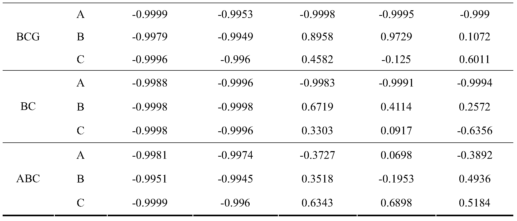
表1不同故障条件下两侧三相电流相关度Table 1 Three-phase current correlation under different fault conditions
以上所述,仅为本发明较佳的具体实施方式,但本发明的保护范围并不局限于此,任何熟悉本技术领域的技术人员在本发明披露的技术范围内,可轻易想到的变化或替换,都应涵盖在本发明的保护范围之内。因此,本发明的保护范围应该以权利要求书的保护范围为准。
The above is only a preferred embodiment of the present invention, but the scope of the present invention is not limited thereto, and any person skilled in the art can easily think of changes or within the technical scope of the present disclosure. Alternatives are intended to be covered by the scope of the present invention. Therefore, the scope of the invention should be determined by the scope of the claims.
Claims (5)
- 一种基于电流波形相似度的新能源场站送出线路纵联保护方法,其特征在于,包括:A new energy field station sending line longitudinal protection method based on current waveform similarity, characterized in that:在新能源场站送出线路的M、N侧分别安装相同的继电保护装置,每一套保护装置均独立测量本侧三相电流,并通过通信信道获取对侧三相电流;The same relay protection device is installed on the M and N sides of the transmission line of the new energy field station, and each set of protection devices independently measures the three-phase current of the current side, and obtains the opposite three-phase current through the communication channel;每套继电保护装置根据本侧和对侧同一时刻对应的相同时间窗长内的同名相电流采样值进行相关系数计算;Each set of relay protection device performs correlation coefficient calculation according to the same-phase current sample value in the same time window length corresponding to the same time and the opposite side at the same time;每一套继电保护装置均根据计算到的每一相电流的相关系数与整定值的大小关系,来判定新能源场站送出线路内部是否发生故障,进而根据故障类别启用相应保护措施。Each set of relay protection devices determines whether there is a fault inside the line sent by the new energy field station according to the calculated relationship between the correlation coefficient of each phase current and the setting value, and then activates corresponding protection measures according to the fault category.
- 根据权利要求1所述的一种基于电流波形相似度的新能源场站送出线路纵联保护方法,其特征在于,利用故障后两个电流波形的相似度这一故障特征来构造保护原理,并采用了相关系数来衡量两个波形的相似度,所述相关系数的计算公式为:The method for protecting a vertical line of a new energy field station based on current waveform similarity according to claim 1, wherein the protection principle is constructed by using a fault feature of the similarity of the two current waveforms after the fault, and The correlation coefficient is used to measure the similarity of the two waveforms, and the correlation coefficient is calculated as:
 其中,rp表示M、N两侧p相电流的相关系数;n为时间窗长N毫秒内的采样点数,满足n=N×0.001×fs,fs为继电保护装置的采样频率;iMp(k)、iMp(j)分别为M侧第k、j个p相电流采样值;iNp(k)、iNp(j)分别为N侧第k、j个p相电流采样值。Where r p represents the correlation coefficient of the p-phase currents on both sides of M and N; n is the number of sampling points in the time window of N milliseconds, which satisfies n=N×0.001×f s , and f s is the sampling frequency of the relay protection device; i Mp (k), i Mp (j) are the k-th and j-th p-phase current samples on the M side; i Np (k) and i Np (j) are the k-th and j-p-phase current samples on the N side, respectively. value.
 - 根据权利要求1所述的一种基于电流波形相似度的新能源场站送出线路纵联保护方法,其特征在于,依据新能源电源控制系统的暂态调节时间,确定了送出线路纵联保护的时间窗长为10ms。The method for protecting a vertical energy line of a new energy field station based on current waveform similarity according to claim 1, wherein the longitudinal line protection of the sending line is determined according to the transient adjustment time of the new energy source control system The time window is 10ms long.
- 根据权利要求1所述的一种基于电流波形相似度的新能源场站送出线路纵联保护方法,其特征在于,所述整定值为-0.9。The method for protecting a vertical line of a new energy field station based on current waveform similarity according to claim 1, wherein the setting value is -0.9.
- 根据权利要求1所述的一种基于电流波形相似度的新能源场站送出线路纵联保护方法,其特征在于,The method for protecting a vertical energy line of a new energy field station based on current waveform similarity according to claim 1, wherein若A相、B相、C相中任一相电流的相关系数大于整定值,则保护判定新能源场站送出线路内部发生单相故障,故障相为相关系数大于整定值的那一相,继电保护装置发出跳开相应故障相别断路器的指令;If the correlation coefficient of any phase current in phase A, phase B, and phase C is greater than the setting value, the protection determines that a single-phase fault occurs inside the transmission line of the new energy field station, and the fault phase is the phase in which the correlation coefficient is greater than the setting value. The electric protection device issues an instruction to trip the corresponding faulty phase breaker;若A相、B相、C相中的任意两相或者三相电流的相关系数大于整定值,则保护判定 新能源场站送出线路内部发生两相或者三相故障,故障相为相关系数大于整定值的那两相或三相,继电保护装置发出跳开三相断路器的指令;If the correlation coefficient of any two phases or three phases of phase A, phase B, and phase C is greater than the setting value, the protection decision Two-phase or three-phase faults occur inside the transmission line of the new energy field station, and the fault phase is the two-phase or three-phase with the correlation coefficient greater than the set value, and the relay protection device issues an instruction to trip the three-phase circuit breaker;若A相、B相与C相电流的相关系数均小于整定值,则保护判定新能源场站送出线路内部未发生故障,继电保护装置不发出跳闸指令。 If the correlation coefficients of the A-phase, B-phase and C-phase currents are less than the set value, the protection determines that there is no fault inside the transmission line of the new energy field station, and the relay protection device does not issue a trip command.
Priority Applications (2)
| Application Number | Priority Date | Filing Date | Title |
|---|---|---|---|
| EP17891483.4A EP3460936B1 (en) | 2017-01-10 | 2017-05-11 | Pilot protection method for transmission line of new energy station based on current waveform similarity |
| DK17891483.4T DK3460936T3 (en) | 2017-01-10 | 2017-05-11 | DIFFERENTIAL PROTECTION METHOD FOR TRANSMISSION LINE FOR NEW ENERGY PLANT BASED ON CURRENT SHAPE SIMILARITY |
Applications Claiming Priority (2)
| Application Number | Priority Date | Filing Date | Title |
|---|---|---|---|
| CN201710017380.3A CN106786424B (en) | 2017-01-10 | 2017-01-10 | Send out method for pilot protection of circuit in new energy station based on current waveform similarity |
| CN201710017380.3 | 2017-01-10 |
Publications (1)
| Publication Number | Publication Date |
|---|---|
| WO2018129842A1 true WO2018129842A1 (en) | 2018-07-19 |
Family
ID=58947447
Family Applications (1)
| Application Number | Title | Priority Date | Filing Date |
|---|---|---|---|
| PCT/CN2017/083926 WO2018129842A1 (en) | 2017-01-10 | 2017-05-11 | Pilot protection method for transmission line of new energy station based on current waveform similarity |
Country Status (4)
| Country | Link |
|---|---|
| EP (1) | EP3460936B1 (en) |
| CN (1) | CN106786424B (en) |
| DK (1) | DK3460936T3 (en) |
| WO (1) | WO2018129842A1 (en) |
Cited By (17)
| Publication number | Priority date | Publication date | Assignee | Title |
|---|---|---|---|---|
| CN109494697A (en) * | 2019-01-08 | 2019-03-19 | 华北电力大学 | A method of the new energy station multiterminal pilot protection based on cosine similarity |
| CN111756025A (en) * | 2020-06-29 | 2020-10-09 | 深圳供电局有限公司 | Method and system for judging line differential protection action based on power grid fault recording diagram |
| CN111934285A (en) * | 2020-09-10 | 2020-11-13 | 桂林五环电器制造有限公司 | Dry-type air-core reactor turn-to-turn short circuit protection method and device |
| CN112271709A (en) * | 2020-11-06 | 2021-01-26 | 国网甘肃省电力公司电力科学研究院 | Time domain distance protection method suitable for wind power plant output line |
| CN113036729A (en) * | 2021-04-12 | 2021-06-25 | 华中科技大学 | Differential protection method, device and system based on Euclidean distance and pearson similarity |
| CN113054633A (en) * | 2019-12-27 | 2021-06-29 | 南京理工大学 | Time-limited current quick-break protection fixed value optimization method for power distribution network access of energy storage power station |
| CN113433456A (en) * | 2021-06-25 | 2021-09-24 | 西安热工研究院有限公司 | Generator fault diagnosis system and method based on current waveform similarity |
| CN113488964A (en) * | 2021-07-27 | 2021-10-08 | 西安热工研究院有限公司 | System and method for protecting high-speed permanent magnet wind driven generator and outgoing cable by electric quantity |
| CN113625190A (en) * | 2021-08-02 | 2021-11-09 | 国网江苏省电力有限公司镇江供电分公司 | Adaptive identification and protection method for 110kV line disconnection fault |
| CN113848429A (en) * | 2021-10-15 | 2021-12-28 | 国网陕西省电力公司电力科学研究院 | Power distribution network single-phase line break fault protection method and system |
| CN113866557A (en) * | 2021-09-25 | 2021-12-31 | 太原理工大学 | Monopole grounding line selection method based on zero-mode current correlation |
| CN114200348A (en) * | 2021-12-06 | 2022-03-18 | 云南电网有限责任公司保山供电局 | Method and system for judging line trip of stability control device |
| CN114498586A (en) * | 2022-01-29 | 2022-05-13 | 河海大学 | Power grid current protection setting method and device for high-proportion fluctuating power supply |
| CN114629089A (en) * | 2022-03-14 | 2022-06-14 | 四川大学 | Single-ended-quantity waveform similarity protection method suitable for flexible direct-current transmission line |
| CN116029152A (en) * | 2023-02-15 | 2023-04-28 | 国网冀北电力有限公司电力科学研究院 | Protection adaptability determination method and device for new energy station |
| CN116466154A (en) * | 2023-03-23 | 2023-07-21 | 国能大渡河流域水电开发有限公司 | Fault diagnosis method and device, storage medium and electronic equipment |
| CN117706281A (en) * | 2024-02-05 | 2024-03-15 | 昆明理工大学 | Fault line selection method, system and storage medium for power distribution network based on phase asymmetry |
Families Citing this family (22)
| Publication number | Priority date | Publication date | Assignee | Title |
|---|---|---|---|---|
| CN107978504B (en) * | 2017-12-31 | 2024-04-12 | 中国电子科技集团公司第十二研究所 | Magnetron energy output device and magnetron comprising same |
| CN108616112A (en) * | 2018-05-07 | 2018-10-02 | 华北电力大学 | A kind of flexible direct current distribution line protection method based on transient current similarity |
| CN109449899B (en) * | 2019-01-14 | 2020-02-18 | 华北电力大学 | Pilot protection method based on spearman grade correlation coefficient |
| CN109787197B (en) * | 2019-01-15 | 2020-02-07 | 三峡大学 | Circuit pilot protection method based on Bhattacharyya distance algorithm |
| CN110161358A (en) * | 2019-04-30 | 2019-08-23 | 云南电网有限责任公司电力科学研究院 | A kind of Earth design method and device |
| CN110112715B (en) * | 2019-05-27 | 2021-08-31 | 三峡大学 | Pilot protection method based on discrete Frechet distance of current sampling values on two sides of line |
| CN110165644B (en) * | 2019-06-03 | 2021-01-01 | 华北电力大学 | New energy station pilot protection method based on transient current time-frequency characteristics |
| CN110504662A (en) * | 2019-07-10 | 2019-11-26 | 山东科技大学 | The longitudinal differential protection method of double-fed fan motor field submitting route |
| CN110492448A (en) * | 2019-07-11 | 2019-11-22 | 华北电力大学 | The distance protecting method of route is sent out suitable for new energy station |
| CN110829388B (en) * | 2019-11-14 | 2021-10-26 | 国网湖南省电力有限公司 | Single-phase earth fault judgment method and reclosing method of double-fed wind power plant |
| CN110880743B (en) * | 2019-12-02 | 2021-03-26 | 华北电力大学 | Kendel rank correlation-based pilot protection method for outgoing line of wind power plant |
| CN111751659B (en) * | 2020-06-29 | 2021-12-14 | 深圳供电局有限公司 | Zero-phase current wiring method and system for judging wave recorder based on power grid fault wave recording diagram |
| CN111896890B (en) * | 2020-08-06 | 2021-10-08 | 山东大学 | Micro-grid line fault diagnosis method and system based on Hilbert-Huang transform |
| CN111987699B (en) * | 2020-08-18 | 2021-08-27 | 广东电网有限责任公司电力调度控制中心 | Current differential protection data synchronization method of alternating current line and related device |
| US10985558B1 (en) * | 2020-08-24 | 2021-04-20 | North China Electric Power University | Structural similarity based pilot protection method and system for renewable power transmission line |
| CN112083284B (en) * | 2020-09-07 | 2021-10-12 | 昆明理工大学 | Method for identifying fault section and fault branch of current collecting line of wind power plant |
| CN112557961B (en) * | 2020-11-06 | 2023-03-21 | 国网河南省电力公司电力科学研究院 | Method for judging fault of double-fed wind power plant outgoing line |
| CN112865032B (en) * | 2021-01-13 | 2023-09-15 | 国网安徽省电力有限公司 | Distributed differential protection method and system for power distribution network adapting to 5G communication network |
| CN114156849A (en) * | 2021-12-10 | 2022-03-08 | 广西电网有限责任公司钦州供电局 | Pilot protection method for high-voltage transmission line based on current waveform correlation |
| CN114966323B (en) * | 2022-06-23 | 2023-06-02 | 中国电力科学研究院有限公司 | Fault identification method and system based on full-time domain mutation information |
| CN117254441B (en) * | 2023-11-16 | 2024-01-26 | 昆明理工大学 | Power distribution network ground fault arc extinguishing method based on active intervention active voltage compensation |
| CN117410947B (en) * | 2023-12-14 | 2024-04-12 | 国网天津市电力公司电力科学研究院 | Differential protection method for new energy station grid-connected line |
Citations (4)
| Publication number | Priority date | Publication date | Assignee | Title |
|---|---|---|---|---|
| US20030060991A1 (en) * | 2001-09-13 | 2003-03-27 | Stoupis James D. | Crossover fault classification for power lines with parallel circuits |
| CN102255291A (en) * | 2011-07-04 | 2011-11-23 | 昆明理工大学 | Simulation after test method for pilot protection of alternating-current transmission line based on Bergeron model |
| CN105356428A (en) * | 2015-11-23 | 2016-02-24 | 国家电网公司 | Time domain model identification pilot protection method suitable for wind power system |
| CN105891676A (en) * | 2016-04-12 | 2016-08-24 | 上海交通大学 | Flexible high-voltage DC line protection method with current correlation |
Family Cites Families (3)
| Publication number | Priority date | Publication date | Assignee | Title |
|---|---|---|---|---|
| CN102288874B (en) * | 2011-07-04 | 2014-07-02 | 昆明理工大学 | After-test simulation method for inner and outer fault recognition of ultra-high voltage alternating-current power transmission line based on lumped parameter T model |
| CN102590704A (en) * | 2012-02-21 | 2012-07-18 | 昆明理工大学 | After-test simulation method for internal and external failure recognition of double-circuit transmission line region based on Bergeron model |
| CN102590693A (en) * | 2012-02-21 | 2012-07-18 | 昆明理工大学 | Simulation after test approach for alternating current (AC) transmission line fault phase selection based on lumped parameter T model |
-
2017
- 2017-01-10 CN CN201710017380.3A patent/CN106786424B/en active Active
- 2017-05-11 EP EP17891483.4A patent/EP3460936B1/en active Active
- 2017-05-11 WO PCT/CN2017/083926 patent/WO2018129842A1/en unknown
- 2017-05-11 DK DK17891483.4T patent/DK3460936T3/en active
Patent Citations (4)
| Publication number | Priority date | Publication date | Assignee | Title |
|---|---|---|---|---|
| US20030060991A1 (en) * | 2001-09-13 | 2003-03-27 | Stoupis James D. | Crossover fault classification for power lines with parallel circuits |
| CN102255291A (en) * | 2011-07-04 | 2011-11-23 | 昆明理工大学 | Simulation after test method for pilot protection of alternating-current transmission line based on Bergeron model |
| CN105356428A (en) * | 2015-11-23 | 2016-02-24 | 国家电网公司 | Time domain model identification pilot protection method suitable for wind power system |
| CN105891676A (en) * | 2016-04-12 | 2016-08-24 | 上海交通大学 | Flexible high-voltage DC line protection method with current correlation |
Non-Patent Citations (2)
| Title |
|---|
| DUAN, JIANDONG ET AL.: "Line Protection Based on Current Frequency Difference for Active Distribution Network", PROCEEDINGS OF THE CSEE, vol. 36, no. 11, 5 June 2016 (2016-06-05), pages 2927 - 2934, XP009515470, ISSN: 0258-8013 * |
| KONG, FEI ET AL.: "A Novel Pilot Protection Scheme for HVDC Transmission Lines Based on Waveform Correlation Analysis of Traveling Wave", DIAN LI XI TONG ZI DONG HUA = AUTOMATION OF ELECTRIC POWER SYSTEMS, vol. 38, no. 20, 25 October 2014 (2014-10-25), pages 108 - 109, XP009515456, ISSN: 1000-1026, DOI: 10.7500/AEPS20130922015 * |
Cited By (31)
| Publication number | Priority date | Publication date | Assignee | Title |
|---|---|---|---|---|
| CN109494697A (en) * | 2019-01-08 | 2019-03-19 | 华北电力大学 | A method of the new energy station multiterminal pilot protection based on cosine similarity |
| CN109494697B (en) * | 2019-01-08 | 2022-08-12 | 华北电力大学 | Cosine similarity-based new energy station multi-end pilot protection method |
| CN113054633A (en) * | 2019-12-27 | 2021-06-29 | 南京理工大学 | Time-limited current quick-break protection fixed value optimization method for power distribution network access of energy storage power station |
| CN113054633B (en) * | 2019-12-27 | 2022-09-16 | 南京理工大学 | Time-limited current quick-break protection fixed value optimization method for power distribution network access of energy storage power station |
| CN111756025A (en) * | 2020-06-29 | 2020-10-09 | 深圳供电局有限公司 | Method and system for judging line differential protection action based on power grid fault recording diagram |
| CN111934285A (en) * | 2020-09-10 | 2020-11-13 | 桂林五环电器制造有限公司 | Dry-type air-core reactor turn-to-turn short circuit protection method and device |
| CN112271709A (en) * | 2020-11-06 | 2021-01-26 | 国网甘肃省电力公司电力科学研究院 | Time domain distance protection method suitable for wind power plant output line |
| CN112271709B (en) * | 2020-11-06 | 2022-09-13 | 国网甘肃省电力公司电力科学研究院 | Time domain distance protection method suitable for wind power plant output line |
| CN113036729B (en) * | 2021-04-12 | 2022-07-12 | 华中科技大学 | Differential protection method, device and system based on Euclidean distance and pearson similarity |
| CN113036729A (en) * | 2021-04-12 | 2021-06-25 | 华中科技大学 | Differential protection method, device and system based on Euclidean distance and pearson similarity |
| CN113433456A (en) * | 2021-06-25 | 2021-09-24 | 西安热工研究院有限公司 | Generator fault diagnosis system and method based on current waveform similarity |
| CN113433456B (en) * | 2021-06-25 | 2022-11-01 | 西安热工研究院有限公司 | Generator fault diagnosis system and method based on current waveform similarity |
| CN113488964A (en) * | 2021-07-27 | 2021-10-08 | 西安热工研究院有限公司 | System and method for protecting high-speed permanent magnet wind driven generator and outgoing cable by electric quantity |
| CN113625190B (en) * | 2021-08-02 | 2022-09-02 | 国网江苏省电力有限公司镇江供电分公司 | Adaptive identification and protection method for 110kV line disconnection fault |
| CN113625190A (en) * | 2021-08-02 | 2021-11-09 | 国网江苏省电力有限公司镇江供电分公司 | Adaptive identification and protection method for 110kV line disconnection fault |
| CN113866557A (en) * | 2021-09-25 | 2021-12-31 | 太原理工大学 | Monopole grounding line selection method based on zero-mode current correlation |
| CN113866557B (en) * | 2021-09-25 | 2023-08-15 | 太原理工大学 | Monopole grounding line selection method based on zero-mode current correlation |
| CN113848429A (en) * | 2021-10-15 | 2021-12-28 | 国网陕西省电力公司电力科学研究院 | Power distribution network single-phase line break fault protection method and system |
| CN113848429B (en) * | 2021-10-15 | 2023-07-18 | 国网陕西省电力公司电力科学研究院 | Single-phase disconnection fault protection method and system for power distribution network |
| CN114200348B (en) * | 2021-12-06 | 2023-07-04 | 云南电网有限责任公司保山供电局 | Circuit tripping judgment method and system for stability control device |
| CN114200348A (en) * | 2021-12-06 | 2022-03-18 | 云南电网有限责任公司保山供电局 | Method and system for judging line trip of stability control device |
| CN114498586A (en) * | 2022-01-29 | 2022-05-13 | 河海大学 | Power grid current protection setting method and device for high-proportion fluctuating power supply |
| CN114498586B (en) * | 2022-01-29 | 2022-11-29 | 河海大学 | Power grid current protection setting method and device for high-proportion fluctuating power supply |
| CN114629089B (en) * | 2022-03-14 | 2023-02-03 | 四川大学 | Single-end-measurement waveform similarity protection method suitable for flexible direct-current transmission line |
| CN114629089A (en) * | 2022-03-14 | 2022-06-14 | 四川大学 | Single-ended-quantity waveform similarity protection method suitable for flexible direct-current transmission line |
| CN116029152A (en) * | 2023-02-15 | 2023-04-28 | 国网冀北电力有限公司电力科学研究院 | Protection adaptability determination method and device for new energy station |
| CN116029152B (en) * | 2023-02-15 | 2024-05-10 | 国网冀北电力有限公司电力科学研究院 | Protection adaptability determination method and device for new energy station |
| CN116466154A (en) * | 2023-03-23 | 2023-07-21 | 国能大渡河流域水电开发有限公司 | Fault diagnosis method and device, storage medium and electronic equipment |
| CN116466154B (en) * | 2023-03-23 | 2023-12-29 | 国能大渡河流域水电开发有限公司 | Fault diagnosis method and device, storage medium and electronic equipment |
| CN117706281A (en) * | 2024-02-05 | 2024-03-15 | 昆明理工大学 | Fault line selection method, system and storage medium for power distribution network based on phase asymmetry |
| CN117706281B (en) * | 2024-02-05 | 2024-06-07 | 昆明理工大学 | Fault line selection method, system and storage medium for power distribution network based on phase asymmetry |
Also Published As
| Publication number | Publication date |
|---|---|
| EP3460936A1 (en) | 2019-03-27 |
| CN106786424B (en) | 2018-11-27 |
| CN106786424A (en) | 2017-05-31 |
| EP3460936A4 (en) | 2020-01-15 |
| DK3460936T3 (en) | 2023-08-14 |
| EP3460936B1 (en) | 2023-07-26 |
Similar Documents
| Publication | Publication Date | Title |
|---|---|---|
| WO2018129842A1 (en) | Pilot protection method for transmission line of new energy station based on current waveform similarity | |
| CN103490394B (en) | The motor synchronizing positive sequence fault component current differential protection method of active power distribution network | |
| US20200341046A1 (en) | Method and apparatus for detecting faults in a three-phase electrical distribution network | |
| He et al. | A DC line protection scheme for MMC-based DC grids based on AC/DC transient information | |
| CN103050933B (en) | Based on the large-sized battery energy-accumulating power station interface protection method of one-terminal current Sudden Changing Rate | |
| CN108802570B (en) | Fault detection system and method for alternating current-direct current series-parallel micro-grid | |
| CN108181550A (en) | A kind of exchange micro-capacitance sensor fault type judges and phase-selecting method | |
| Liu et al. | A novel pilot directional protection scheme for HVDC transmission line based on specific frequency current | |
| Priya et al. | Design and development of distance protection scheme for wind power distributed generation | |
| Tajani et al. | A novel differential protection scheme for AC microgrids based on discrete wavelet transform | |
| Li et al. | Analysis and calculation method for multiple faults in low-resistance grounded systems with inverter-interfaced distributed generators based on a PQ control strategy | |
| Sazli et al. | A brief review of power quality issues in smart grid and a simple user friendly software | |
| CN104979808B (en) | A kind of inverter calculation of penetration level method counted and longitudinal difference protection influences | |
| Eltamaly et al. | HVDC over HVAC transmission system: Fault conditions stability study | |
| CN104167755B (en) | Method for determining commutation failure area caused by single-phase short circuit | |
| CN103728537B (en) | A kind of fault direction judgement system of no-voltage dead band and method of discrimination | |
| Zhao et al. | A passive islanding detection method based on interharmonic impedance | |
| CN113437732B (en) | Pilot protection method and system for photovoltaic power generation grid-connected tie line | |
| Sun et al. | A novel method for pilot protection based on current fault component | |
| Kocar et al. | Nonlinear network equivalents of systems with inverter based resources to study unbalanced faults in steady state | |
| CN109245057B (en) | Time domain full-waveform protection device for power transmission line and interphase mutation direction judgment method | |
| Fei et al. | Digital-analog simulation test of grid-connected performance for string inverter | |
| Xin et al. | Single Phase Ground Fault Locating Method of Multi-Branch Wind Farm Collector Lines | |
| Zhang et al. | Fault location in active distribution network based on the change of current phase | |
| Liu et al. | Short-circuit Current and Current Protection Influence Analysis for Distribution Network with Distribution Generator Access Based on Short-circuit Ratio |
Legal Events
| Date | Code | Title | Description |
|---|---|---|---|
| 121 | Ep: the epo has been informed by wipo that ep was designated in this application |
Ref document number: 17891483 Country of ref document: EP Kind code of ref document: A1 |
|
| ENP | Entry into the national phase |
Ref document number: 2017891483 Country of ref document: EP Effective date: 20181218 |
|
| NENP | Non-entry into the national phase |
Ref country code: DE |