WO2018124018A1 - パーライトおよびその製造方法、ならびに水処理方法および水処理材 - Google Patents
パーライトおよびその製造方法、ならびに水処理方法および水処理材 Download PDFInfo
- Publication number
- WO2018124018A1 WO2018124018A1 PCT/JP2017/046539 JP2017046539W WO2018124018A1 WO 2018124018 A1 WO2018124018 A1 WO 2018124018A1 JP 2017046539 W JP2017046539 W JP 2017046539W WO 2018124018 A1 WO2018124018 A1 WO 2018124018A1
- Authority
- WO
- WIPO (PCT)
- Prior art keywords
- pearlite
- zeolite
- particle size
- modified
- solution
- Prior art date
- Legal status (The legal status is an assumption and is not a legal conclusion. Google has not performed a legal analysis and makes no representation as to the accuracy of the status listed.)
- Ceased
Links
Images
















Classifications
-
- B—PERFORMING OPERATIONS; TRANSPORTING
- B01—PHYSICAL OR CHEMICAL PROCESSES OR APPARATUS IN GENERAL
- B01J—CHEMICAL OR PHYSICAL PROCESSES, e.g. CATALYSIS OR COLLOID CHEMISTRY; THEIR RELEVANT APPARATUS
- B01J20/00—Solid sorbent compositions or filter aid compositions; Sorbents for chromatography; Processes for preparing, regenerating or reactivating thereof
- B01J20/02—Solid sorbent compositions or filter aid compositions; Sorbents for chromatography; Processes for preparing, regenerating or reactivating thereof comprising inorganic material
- B01J20/10—Solid sorbent compositions or filter aid compositions; Sorbents for chromatography; Processes for preparing, regenerating or reactivating thereof comprising inorganic material comprising silica or silicate
- B01J20/12—Naturally occurring clays or bleaching earth
-
- B—PERFORMING OPERATIONS; TRANSPORTING
- B01—PHYSICAL OR CHEMICAL PROCESSES OR APPARATUS IN GENERAL
- B01J—CHEMICAL OR PHYSICAL PROCESSES, e.g. CATALYSIS OR COLLOID CHEMISTRY; THEIR RELEVANT APPARATUS
- B01J20/00—Solid sorbent compositions or filter aid compositions; Sorbents for chromatography; Processes for preparing, regenerating or reactivating thereof
- B01J20/30—Processes for preparing, regenerating, or reactivating
-
- C—CHEMISTRY; METALLURGY
- C01—INORGANIC CHEMISTRY
- C01B—NON-METALLIC ELEMENTS; COMPOUNDS THEREOF; METALLOIDS OR COMPOUNDS THEREOF NOT COVERED BY SUBCLASS C01C
- C01B33/00—Silicon; Compounds thereof
- C01B33/20—Silicates
- C01B33/26—Aluminium-containing silicates, i.e. silico-aluminates
-
- C—CHEMISTRY; METALLURGY
- C01—INORGANIC CHEMISTRY
- C01B—NON-METALLIC ELEMENTS; COMPOUNDS THEREOF; METALLOIDS OR COMPOUNDS THEREOF NOT COVERED BY SUBCLASS C01C
- C01B39/00—Compounds having molecular sieve and base-exchange properties, e.g. crystalline zeolites; Their preparation; After-treatment, e.g. ion-exchange or dealumination
- C01B39/02—Crystalline aluminosilicate zeolites; Isomorphous compounds thereof; Direct preparation thereof; Preparation thereof starting from a reaction mixture containing a crystalline zeolite of another type, or from preformed reactants; After-treatment thereof
-
- C—CHEMISTRY; METALLURGY
- C02—TREATMENT OF WATER, WASTE WATER, SEWAGE, OR SLUDGE
- C02F—TREATMENT OF WATER, WASTE WATER, SEWAGE, OR SLUDGE
- C02F1/00—Treatment of water, waste water, or sewage
- C02F1/28—Treatment of water, waste water, or sewage by sorption
Definitions
- the present invention relates to perlite useful for liquid filtration technology, a method for producing the same, a water treatment method, and a water treatment material.
- Perlite is a powder obtained by using pearlite as a raw material and foaming by crushing and heat treatment.
- This pearlite contains aluminum silicate as a main component, and is used, for example, as a filter aid.
- Patent Document 1 discloses a method of filtering using perlite as a filter aid.
- Patent Document 1 discloses that powders such as activated carbon, zeolite, and calcium salt are mixed and used as a filter aid in addition to pearlite.
- Patent Document 2 discloses an artificial zeolite (surface-modified pearlite) in which a part of pearlite is zeoliteized. It is disclosed that this artificial zeolite is produced by heating a mixture containing pearlite and an alkali metal hydroxide in the presence of water.
- Patent Document 3 discloses a first step of obtaining a first powder by pulverizing a first raw material made of inorganic glass (pearlite) with a dry ball mill, and a second step of obtaining a second raw material made of countless fine bamboo fibers. Two steps, a third step of mixing the first powder and the second raw material in a basic aqueous solution to obtain a first reaction solution, and a fourth step of obtaining a second reaction solution by depressurizing the first reaction solution. And a fifth step of hydrothermally treating the second reaction liquid to obtain a zeolite structure, a method for producing a zeolite structure is disclosed.
- zeolite has chemical characteristics such as ion exchange characteristics and adsorption characteristics, and is required to have both the filtration function of perlite and the chemical characteristics of zeolite.
- Patent Document 1 when zeolite is mixed in addition to pearlite and used as a filter aid, the filtration function of pearlite may be greatly reduced due to inclusion of zeolite.
- the artificial zeolite described in Patent Document 2 may have a sufficient filtration function when part of pearlite is zeoliticized, but a mixture containing pearlite and alkali metal hydroxide is produced at a high temperature during production. There is a problem that the manufacturing cost increases.
- the present invention has been made in view of the above, and an object of the present invention is to provide pearlite capable of achieving both the filtration function of pearlite and the chemical characteristics of zeolite, a method for producing the same, a water treatment method, and a water treatment material. It is to provide.
- the pearlite according to one aspect of the present invention is a pearlite having a structure in which a zeolite is formed, and the pearlite is between the pearlite and the zeolite. It is characterized by having a portion continuously changing from the amorphous structure to the crystal structure of the zeolite.
- the pearlite according to one aspect of the present invention is pearlite having a structure in which zeolite is formed, and at least a particle size distribution of the pearlite powder after the pearlite powder is irradiated with ultrasonic waves for a predetermined time or more.
- the particle size that becomes one peak is approximately equal to the particle size that becomes at least one peak of the particle size distribution in the pearlite powder before irradiation with the ultrasonic wave.
- the pearlite according to one aspect of the present invention is the pearlite powder according to the above-described invention, wherein at least one peak of a particle size distribution after the ultrasonic wave is irradiated to the pearlite powder for a first predetermined time, and the pearlite powder
- at least one peak of the particle size distribution after the ultrasonic wave is irradiated for a second predetermined time longer than the first predetermined time is approximately equal to each other.
- the method for producing pearlite according to one embodiment of the present invention includes a preparation step in which pearlite is added to and mixed with an aqueous solution of an alkali metal hydroxide in which an aluminum salt is dissolved, and the solution obtained in the preparation step is heated. And a heating step.
- the method for producing pearlite according to one embodiment of the present invention is characterized in that the concentration of the alkali metal hydroxide aqueous solution is 0.3 mol / L or more and 1.0 mol / L or less.
- the water treatment method according to one aspect of the present invention comprises Al, Cr, Mn, Fe, Co, Ni, Cu, Zn, Cd, Pb, Cs, and Sr in an aqueous solution using the pearlite according to the above invention. It is characterized by adsorbing at least one element selected from the group.
- a water treatment material according to an aspect of the present invention is a water treatment material containing pearlite according to the above invention, and includes Al, Cr, Mn, Fe, Co, Ni, Cu, Zn, Cd, Pb, and Cs in an aqueous solution. And at least one element selected from the group consisting of Sr can be adsorbed.
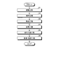
- FIG. 1 is a flowchart of a method for producing a surface-modified pearlite according to an embodiment of the present invention.
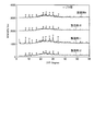
- FIG. 2 is a diagram showing experimental results of the XRD measurement of Example 1.
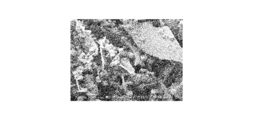
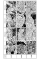
- FIG. 3A is a diagram showing an example of an SEM image of the specimen of Production Example 2.
- FIG. 3B is a diagram illustrating an example of an SEM image of the specimen of Production Example 3.
- FIG. 3C is a diagram showing an example of an SEM image of the specimen of Production Example 3.
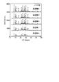
- FIG. 4 is a diagram showing experimental results of XRD measurement in Example 2.
- FIG. 5 is a diagram showing experimental results of XRD measurement of Example 3.
- FIG. 6 is a diagram showing experimental results of XRD measurement of Example 4.
- FIG. 5 is a diagram showing experimental results of XRD measurement of Example 3.
- FIG. 7 is a diagram showing experimental results of XRD measurement of Example 5.
- FIG. 8 is an SEM image showing a state before the experiment in the surface-modified pearlite used in Example 6.
- FIG. 9 is an SEM image showing the state of the surface-modified pearlite after the experiment in Example 6.
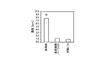
- FIG. 10A is a diagram showing experimental results for Al of Example 6.
- FIG. 10B is a diagram showing experimental results for Cr in Example 6.
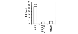
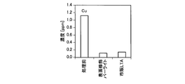
- FIG. 10C is a diagram showing experimental results for Cu in Example 6.
- FIG. 10D is a diagram showing experimental results for Cd of Example 6.
- FIG. 10E is a diagram showing experimental results for Pb of Example 6.
- FIG. 11A is a diagram showing experimental results for Al of Example 6.
- FIG. 11B is a diagram showing experimental results for Cr of Example 6.
- FIG. 11A is a diagram showing experimental results for Al of Example 6.
- FIG. 11B is a diagram showing experimental results for Cr of Example 6.
- FIG. 11C is a diagram showing experimental results for Cu in Example 6.
- FIG. 11D is a diagram showing experimental results for Cd of Example 6.
- FIG. 11E is a diagram showing experimental results for Pb of Example 6.
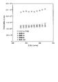
- FIG. 12 is a diagram illustrating experimental results of Example 7.
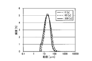
- FIG. 13 is a graph showing the particle size distribution before and after the ultrasonic irradiation of the surface-modified pearlite powder in Example 8.
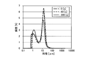
- FIG. 14 is a graph obtained by measuring the particle size distribution before and after ultrasonic irradiation on a powder composed of zeolite without pearlite.
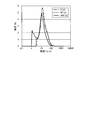
- FIG. 15 is a graph showing the particle size distribution measured before and after ultrasonic irradiation on a mixed powder obtained by simply mixing pearlite powder and zeolite powder as a comparative example to be compared with the surface-modified pearlite according to Example 8. It is.
- FIG. 16A is a diagram showing an example of a TEM image of the surface-modified pearlite produced in Example 8.
- FIG. 16B is a diagram illustrating an example of an electron beam diffraction image in a box B in FIG. 16A.
- FIG. 16C is a diagram illustrating an example of an electron beam diffraction image in a box C in FIG. 16A.
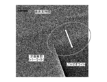
- FIG. 17 is a diagram showing an example of a TEM image showing the surface-modified pearlite formed on the carbon support film.
- FIG. 18 is a diagram illustrating examples of SEM images magnified 2000 times, 5000 times, and 15000 times for each concentration of sodium hydroxide in the generated surface-modified perlite.
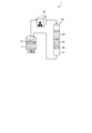
- FIG. 19 is a block diagram for explaining a Cs adsorption test method by circulating adsorption.
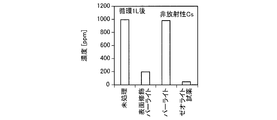
- FIG. 20A is a diagram showing an experimental result when a Cs solution is circulated by 1 L in a non-radioactive Cs circulation adsorption test.
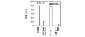
- FIG. 20B is a diagram showing an experimental result when the Cs solution is circulated by 2 L in the non-radioactive Cs circulation adsorption test.
- FIG. 20C is a diagram illustrating an experimental result when the Cs solution is circulated by 3 L in the non-radioactive Cs circulation adsorption test.
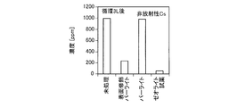
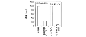
- FIG. 21A is a diagram showing an experimental result after standing for 0 hour in a stationary adsorption test of non-radioactive Cs.
- FIG. 21B is a diagram showing experimental results after standing for 1 hour in a static adsorption test for non-radioactive Cs.
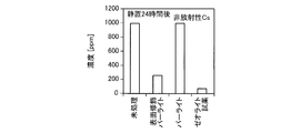
- FIG. 21C is a diagram showing experimental results after standing for 24 hours in a static adsorption test for non-radioactive Cs.
- FIG. 22 is a diagram showing experimental results of a cyclic adsorption test for radioactive Cs.
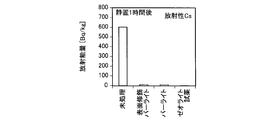
- FIG. 23A is a diagram showing an experimental result after standing for 0 hour in a stationary adsorption test for radioactive Cs.
- FIG. 23B is a diagram showing experimental results after standing for 1 hour in a stationary adsorption test for radioactive Cs.
- FIG. 23C is a diagram showing an experimental result after standing for 24 hours in a stationary adsorption test for radioactive Cs.
- the pearlite according to the embodiment of the present invention is a pearlite having a structure in which a zeolite is formed, and continuously changes from the amorphous structure of pearlite to the crystalline structure of zeolite between the pearlite and the zeolite.
- Perlite with part. In this specification, perlite having such a structure is referred to as surface-modified perlite.
- the surface-modified pearlite contains, for example, Si, Al, K, Na, Fe, Ca, O and the like as constituent elements.
- the Si / Al molar ratio Si / Al is set to 4.3 or less.
- the molar ratio Si / Al between Si and Al is preferably 1.79 or more and 3.75 or less. This molar ratio Si / Al can be obtained by conducting a semi-quantitative analysis on the surface-modified pearlite using a fluorescent X-ray analyzer and calculating the molar ratio of Al and Si from the measured weight.
- Pearlite is a powder foamed by crushing and heat treatment using pearlite as a raw material, and its chemical composition has an amorphous structure mainly composed of aluminum silicate.
- This pearlite is porous and lightweight, and has excellent heat insulation, fire resistance, and chemical resistance.
- the particle size of pearlite is, for example, 5 ⁇ m or more and 5000 ⁇ m or less.
- the average particle size of pearlite is preferably 100 ⁇ m or less.
- Zeolite is an aluminosilicate and has ion exchange characteristics and adsorption characteristics.
- Examples of the zeolite include LTA type zeolite and FAU type zeolite.
- FIG. 1 is a flowchart of a method for producing a surface-modified pearlite according to an embodiment of the present invention.
- This method for producing surface-modified pearlite includes, for example, a preparation step S1, a stirring step S2, an aging step S3, a heating step S4, a suction filtration step S5, and a drying / pulverizing step S6.
- preparation process S1 is performed.
- pearlite and an aluminum salt are prepared and added to an aqueous solution of an alkali metal hydroxide.
- the pearlite is, for example, mass%, SiO 2 : 75.0%, Al 2 O 3 : 14.0%, Fe 2 O 3 : 0.9%, CaO: 0.1%, K 2 O: 4.2. %, Na 2 O: 3.5%, and those having a component composition consisting of the balance are used.
- the aluminum salt is, for example, sodium aluminate, potassium aluminate, aluminum sulfate or the like, and sodium aluminate is used as the aluminum salt in this embodiment.
- the alkali metal hydroxide include sodium hydroxide and potassium hydroxide.
- sodium hydroxide is used as the alkali metal hydroxide.
- pearlite is added to an aqueous sodium hydroxide solution as an aqueous solution of an alkali metal hydroxide in which sodium aluminate as an aluminum salt is dissolved in the preparation step S1.
- concentration of the sodium hydroxide aqueous solution is set to 0.1 mol / L or more and 1.0 mol / L or less, preferably 0.3 mol / L or more, or 0.8 mol / L or less.
- pearlite and sodium aluminate are set such that, for example, the molar ratio Si / Al between Si and Al is less than 2.5.
- the range of preferable Si / Al is 0.5 or more and 2.0 or less, More preferably, it is 0.5 or more and 1.5 or less.
- Si / Al is the ratio of the molar amount of Si in pearlite to the sum of the molar amount of Al in pearlite and the molar amount of Al in sodium aluminate.
- heating is performed in the heating step S4.
- it heats to 100 degrees C or less in a normal pressure, without pressurizing. That is, in the present embodiment, surface-modified pearlite is produced without using an autoclave.
- zeolite is formed on the surface of the pearlite.
- the heating temperature is preferably 80 ° C. or lower. Although the minimum of heating temperature is not specifically limited, For example, 30 degreeC or more is preferable. A more preferable range of the heating temperature is 45 ° C. or higher and 75 ° C. or lower.
- suction filtration step S5 suction filtration is performed on the solution after the heating step S4. Thereby, the solution is filtered, and the solid and the liquid in the solution are separated.
- drying / pulverization step S6 the solid separated in the suction filtration step S5 is dried and then pulverized. In this way, the surface-modified pearlite according to this embodiment is manufactured.
- zeolite can be synthesized on the surface of pearlite to modify the surface of pearlite.
- This surface-modified perlite is formed by substituting the surface of perlite with zeolite, and has both the characteristics of perlite as a filtration function and the characteristics of zeolite as adsorption and cation exchange characteristics. This characteristic can be controlled by adjusting the particle size of pearlite and the amount of zeolite formed.
- zeolite can be synthesized at a lower temperature in the heating step. That is, in the method for producing surface-modified pearlite according to the present embodiment, by adding pearlite to an aqueous solution of an alkali metal hydroxide without adding an aluminum salt, by heating at a lower temperature than in the case of hydrothermal synthesis. Zeolite can be synthesized. Therefore, it is possible to reduce the manufacturing cost by lowering the heating during manufacturing.
- sodium aluminate is used as the aluminum salt and sodium hydroxide is used as the alkali metal hydroxide, so that zeolite can be synthesized efficiently and the heating temperature in the heating process can be lowered. Is possible.
- zeolite in the method for producing a surface-modified pearlite according to the present embodiment, since it is configured as described above, zeolite can be synthesized on the surface of pearlite by heating the temperature of the solution to 100 ° C. or lower in the heating step. .
- zeolite in the method for producing surface-modified pearlite according to the present embodiment, can be synthesized on the surface of pearlite at normal pressure without the need for an apparatus such as an autoclave.
- the above-mentioned surface modification pearlite can be manufactured even by heating at a low temperature of less than 80 ° C.
- the surface-modified pearlite produced by the method for producing the surface-modified pearlite according to the present embodiment can be suitably used as a water treatment material, for example, as a filter aid.
- This filter aid has both a filtration function and a function of adsorption and cation exchange characteristics. For example, it can perform so-called water treatment in which filtration is performed while adsorbing cations of water to be filtered.
- the above-mentioned filter aid is mixed with the water to be filtered, and the water to be filtered is filtered through the filter medium.
- Example 1 Next, examples of the present invention will be described. First, Example 1 will be described. Perlite (LocaHelp 439: Mitsui Metal Mining Co., Ltd.) and sodium aluminate shown in Table 1 were added to 15 ml of 1 mol / L sodium hydroxide aqueous solution and stirred. In addition, Si / Al in a table
- Perlite LicaHelp 439: Mitsui Metal Mining Co., Ltd.
- 3A is a 2000 times SEM image of the specimen of Production Example 2
- FIG. 3B is a 2000 times SEM image of the specimen of Production Example 3
- FIG. 3C is a 15000 times SEM image of the specimen of Production Example 3. It is. From the results of SEM observation, it was also confirmed that the specimen of Production Example 1 had a lower amount of zeolite synthesized than the specimens of Production Examples 2-4.
- Example 2 Next, a second embodiment of the present invention will be described.
- Example 2 specimens of Production Examples 5 to 8 were produced in the same manner as described in Example 1 except that the conditions of Si / Al and heating temperature were changed to the conditions shown in Table 2 ( (See Table 2). Specifically, the heating temperature was set to 75 ° C.
- the crystal structure analysis by XRD and the structure observation by SEM were performed as in Example 1. The result of the crystal structure analysis by XRD is shown in FIG. In FIG. 4, the description of the experimental results of Production Example 7 is omitted.
- Example 3 Embodiment 3 of the present invention will be described.
- specimens of Production Examples 9 to 12 were produced in the same manner as described in Example 1 except that the heating temperature condition was changed to 45 ° C. (see Table 3).
- the crystal structure analysis by XRD and the structure observation by SEM were performed. The results of crystal structure analysis by XRD are shown in FIG.
- Si / Al is 0.5 or more and 1.5 or less from the balance of the amount of zeolite formed and the ratio of pearlite to zeolite. It is preferable to set the range.
- Example 4 Next, a fourth embodiment of the present invention will be described.
- Example 4 it was investigated whether or not an autoclave was necessary when producing surface-modified pearlite.
- a specimen of surface-modified pearlite was produced in the same manner as described in Example 1 except that Si / Al shown in Table 4 was obtained using an autoclave container.
- the solution was put into a ceramic container without using an autoclave container so as to be Si / Al as shown in Table 4, and the others were provided with the surface-modified pearlite in the same manner as described in Example 1.
- a specimen was prepared.
- Production Example 15 was conducted in the same manner as in Example 1 except that LokaHelp 439 and sodium aluminate shown in Table 4 were added to sodium hydroxide so that a 700 ml solution was obtained in a 1 L resin container. A specimen of modified perlite was prepared.
- Example 5 Next, a fifth embodiment of the present invention will be described.
- Example 5 the relationship between the conversion rate of pearlite to zeolite and time was examined. Under the conditions shown in Table 5, specimens of Production Examples 16 to 20 were produced. The heating time was set in the range of 24 h to 120 h.
- Example 6 Next, a sixth embodiment of the present invention will be described.
- an ion adsorption test of the surface-modified pearlite was performed.
- Cd, Cu, Pb, Zn, Mn, Fe, Co, Ni, Al, Cr, Cs, and Sr standard solutions (20 ml, 10 ppm) were prepared.
- 18 wt.% Of the solution shown in No. 18 was added to the solution and immersed for 1 to 12 hours. Thereafter, filtration was performed, the filtrate was collected, and ICP (Inductively Coupled Plasma) measurement was performed.
- ICP Inductively Coupled Plasma
- Reagent LTA type zeolite Zeolum A-4, powder (commercially available from Tosoh Corporation)
- Reagent FAU type zeolite HSZ-300 (320NAA) (commercially available from Tosoh Corporation)
- HSZ-300 320NAA
- FIG. 8 shows an SEM image of the surface-modified pearlite before the adsorption test.
- Table 7 is Cd ion
- Table 8 is Cu ion
- Table 9 is Pb ion
- Table 10 is Zn ion
- Table 11 is Mn ion
- Table 12 is Fe ion
- Table 13 is Co ion
- Table 14 is Ni ion
- Table 15 shows the measurement results for Al ions
- Table 16 for Cr ions Table 17 for Cs ions
- Table 18 for Sr ions.
- SEM observation result of the surface modification pearlite after an adsorption test is shown in FIG.
- Example 6 an adsorption test was further performed using mine drainage containing various ions (Al, Cr, Cu, Cd, Pb). The experiment was conducted with the adsorption time being 10 minutes and 30 minutes, and the ratio of the adsorbent to the mine drainage was 10 mg: 10 ml.
- 10A to 10E show experimental results when the adsorption time is 10 minutes
- FIGS. 11A to 11E show experimental results when the adsorption time is 30 minutes.
- 10A to 10E and FIGS. 11A to 11E correspond to adsorption tests for various ions (Al, Cr, Cu, Cd, Pb), respectively.
- the surface-modified pearlite of the present invention is at least selected from the group consisting of Al, Cr, Mn, Fe, Co, Ni, Cu, Zn, Cd, Pb, Cs, and Sr in an aqueous solution as a water treatment material. It is configured to be able to adsorb one kind of element.
- Example 7 Next, a seventh embodiment of the present invention will be described.
- the cake specific resistance of the surface-modified pearlite was measured.
- a method for measuring cake specific resistance will be described below.
- distilled water is taken into a washing bottle and preheated to 30 ° C. with a water heater.
- the beaker is set in the filter.
- the filter paper No. 2 is fixed to the filter with a clip.
- the two-way cock is closed and the vacuum pump is started, and the negative pressure is adjusted to 200 mmHg.
- the two-way cock is not dropped, and at this time, the negative pressure is set to 200 mmHg.
- the sample adhering to the inside of the filter is washed away with a washing bottle.
- 250 ml of distilled water (warmed to 30 ° C.) is gently poured into the filter so as not to roughen the cake surface.
- the filtration time ⁇ of 100 ml in which the filtrate accumulated in the 300 ml beaker set in the filter passes between 300 ml from 200 ml is measured.
- the two-way cock is closed, the cake is taken out of the filter, and the thickness hcm of the cake is measured.
- cake specific resistance a is computed with the following formula
- ⁇ (cake bulk density) is the bulk density of the auxiliary agent (surface modified pearlite) before filtration.
- Example 7 an experiment was conducted to measure the cake specific resistance (average specific resistance) a by the above-described method using the specimen prepared in Example 5 as the surface-modified pearlite. Here, experimental data was obtained by varying the negative pressure (pressure). For comparison, an experiment was also conducted to measure the cake specific resistance of RocaHelp 439 that was not surface-modified. The results of this experiment are shown in FIG.
- the surface-modified pearlite produced in this example had a filtration function. Moreover, although the formation amount of the zeolite increased with heating time, it turned out that a big difference is not seen by the filtration function.
- the filtration characteristics can be controlled by controlling the particle size of the initial pearlite, and the adsorption characteristics can be controlled by controlling the synthesis amount of zeolite.
- Example 8 Next, an eighth embodiment of the present invention will be described.
- the particle size distribution before and after ultrasonic irradiation was measured for the surface-modified pearlite powder of Production Example 3 produced based on the method for producing surface-modified pearlite according to Example 1 described above.
- FIG. 13 is a graph obtained by measuring the particle size distribution before and after ultrasonic irradiation.
- a particle size distribution measuring device “Microtrac MT3000EXII” (manufactured by Microtrack Bell Co., Ltd.), which is a laser diffraction / scattering particle size distribution measuring device, is used. This was performed while operating the ultrasonic device attached to the distribution measuring device.
- the peak of the particle size distribution is about 20 ⁇ m. It can be seen that there is one particle size.
- a particle size of about 20 ⁇ m is present in about 5.2% of the total amount (hereinafter, the frequency is about 5.2%).
- the particle size distribution of pearlite used in Example 8 had a particle size distribution substantially equal to the particle size distribution before irradiation with ultrasonic waves shown in FIG.
- the peak of the particle size distribution is about 20 ⁇ m even after irradiating ultrasonic waves for 60 seconds (1 minute) as the first predetermined time (60 [s]: broken line). It can be seen that there is one particle size. That is, it can be seen that the particle diameters at which the particle size distribution peaks are approximately equal before the ultrasonic wave irradiation and after the ultrasonic wave irradiation for 60 seconds. In addition, after the ultrasonic irradiation for 60 seconds, the frequency of the particle size of about 20 ⁇ m is about 5.0%.
- the particle size distribution after 300 seconds (5 minutes) of ultrasonic waves as a second predetermined time longer than the first predetermined time (300 [s]: solid line) is similarly determined. It can be seen that one distribution peak exists with a particle size of about 20 ⁇ m.
- the particle sizes at which the particle size distribution peaks are substantially the same before irradiation with ultrasonic waves, after irradiation with ultrasonic waves for 60 seconds, and after irradiation with ultrasonic waves for 300 seconds. You can see that they are equal. This is considered to be due to the presence of surface-modified perlite without separation of perlite and zeolite. That is, between the pearlite and the zeolite, the zeolite and the pearlite are combined as a crystal structure by having a portion that continuously changes from the amorphous structure of the pearlite to the crystal structure of the zeolite. it is conceivable that.
- FIG. 14 is a graph obtained by measuring the particle size distribution before and after ultrasonic irradiation on a powder composed of zeolite without pearlite.
- FIG. 15 is a graph showing the particle size distribution measured before and after ultrasonic irradiation on a mixed powder obtained by simply mixing pearlite powder and zeolite powder as a comparative example to be compared with the surface-modified pearlite according to Example 8. It is.
- For pearlite and zeolite the same materials as those used for the production of the surface-modified pearlite are used.
- the particle size distribution is about 2 to about 2 ⁇ m and about 20 ⁇ m. There is a peak. Then, it can be seen that these two particle size distribution peaks are approximately equal to the two particle size distribution peaks before irradiation with ultrasonic waves (indicated by a one-dot chain line in FIG. 14). Note that after the ultrasonic irradiation for 60 seconds, the frequency of the particle size of about 1 to 2 ⁇ m is about 2.5%, and the frequency of the particle size of about 20 ⁇ m is about 6.0%.
- the frequency is about 1-2 ⁇ m and the frequency is about 3.0%. It can be seen that there are two particle size distribution peaks at about 20 ⁇ m and a frequency of about 4.5%. That is, it can be seen that in the powder composed only of zeolite, the particle diameters that are two peaks in the particle size distribution are approximately equal before and after the ultrasonic irradiation.
- the particle size distribution shown in FIG. 15 is obtained. That is, as shown in FIG. 15, before irradiating the mixed powder with ultrasonic waves (0 [s]: one-dot chain line), the particle size is about 20 ⁇ m due to the particle size distribution of pearlite. It can be seen that there is one peak. In this mixed powder, it can be seen that the frequency of the particle size of about 20 ⁇ m is about 5.7%.
- the peak of the particle size distribution further appears at a particle size of about 5 ⁇ m.
- a particle size distribution peak exists even at a particle size of about 20 ⁇ m.
- the peak of the particle size distribution is about 1 ⁇ m and the frequency is about 2.3. %, And about 20 ⁇ m, the frequency appears to be about 4.8%.
- the particle size distribution of the zeolite powder shown in FIG. This is considered due to the fact that the zeolite and the pearlite are separated by continuing the irradiation of the mixed powder with ultrasonic waves.
- the zeolite only adheres to the surface of pearlite, and it is easily separated by irradiating with ultrasonic waves, so that surface-modified pearlite cannot be obtained. It was done. That is, from FIG. 13 to FIG. 15, it was confirmed that the surface-modified pearlite has a structure in which zeolite is bonded to pearlite, unlike a mixed powder obtained by simply mixing zeolite and pearlite.
- the zeolite particles obtained by the method for producing the surface-modified pearlite according to the above-described embodiment are smaller than the pearlite particles and are generated on the surface portions of the pearlite particles as described later (see FIGS. 16 and 18).
- This zeolite particle has a portion that continuously changes from the surface portion of the pearlite particles, so that the pearlite particles can be firmly bonded to the zeolite particles, and even if irradiated with ultrasonic waves, the pearlite particles are separated from the pearlite particles. Does not separate easily.
- the particle size peak of the fine particle portion that depends on the zeolite particles is not separated from the particle size peak that depends on the pearlite particles. Accordingly, it is considered that the performance as a filter aid possessed by the pearlite particles themselves can be maintained for a long period of time.
- the inventors of the present invention have limited field electron using a transmission electron microscope (TEM) for the purpose of structural analysis at the nanoscale site for the surface-modified pearlite powder according to Example 8.
- SAED Selected Area Electron Diffraction
- SAED Selected Area Electron Diffraction
- FIG. 16A is a diagram showing an example of a TEM image of the surface-modified pearlite produced in Example 8, and FIGS. 16B and 16C show examples of electron diffraction images in the enclosing portions B and C of FIG. 16A, respectively.
- FIG. FIG. 17 is a diagram showing an example of a TEM image showing the surface-modified pearlite formed on the carbon support film.
- the rectangular parallelepiped portion is a portion that is characteristic of zeolite (LTA type zeolite). Therefore, the present inventor selects a rectangular parallelepiped part (enclosed part B) and an indeterminate part (enclosed part C) with a limited field stop, acquires an electron diffraction pattern, The structure was confirmed. As a result, as shown in FIG. 16B, it was confirmed that there is a crystal structure in the rectangular parallelepiped portion, and the period of the crystal belongs to the cubic LTA structure. Further, as shown in FIG.
- the electron diffraction pattern in the irregular-shaped portion was a halo pattern having no diffraction peak peculiar to amorphous.
- a low electron dose observation technique is used for observation, and analysis is performed with a very low dose.
- the TEM image shown in FIG. 16C is not made amorphous due to damage due to electron beam irradiation, but the amorphous material itself is amorphous in nature. It shows that the part is pearlite. From the above, it was confirmed by observation using TEM that an LTA-type zeolite having a rectangular parallelepiped shape and an LTA structure was formed on an amorphous part having an irregular shape.
- the present inventor observed the crystal structure between pearlite and zeolite in the surface-modified pearlite formed on the carbon support film.
- the result is shown in FIG. From FIG. 17, it can be seen that the density changes from a light part to a dark part from the pearlite on the carbon support membrane toward the zeolite in the enclosed part.
- the crystal structure of the surface-modified pearlite on the carbon support membrane has a portion that continuously changes from amorphous pearlite to crystalline zeolite. That is, it can be confirmed that the amorphous structure in pearlite gradually changes into a crystal structure in the direction of the arrow in the enclosed portion in the enclosed portion in FIG. 17 and finally becomes a crystalline structure of zeolite. .
- the amorphous structure of pearlite is continuously changed to the crystal structure of zeolite, and in this continuously changed portion (the enclosed portion in FIG. 17), pearlite and zeolite are chemically converted. It was confirmed that they were firmly bonded to each other.
- the particle size at the peak of the particle size distribution after irradiating the pearlite powder with ultrasonic waves for a predetermined time or more does not move before irradiating the ultrasonic waves. It becomes substantially equal to the particle size at the peak of the particle size distribution in the powder.
- each particle size in the particle size distribution of the surface-modified pearlite is determined after the ultrasonic wave is irradiated for a predetermined time or more. Even if there is, it hardly moves. That is, even when the surface-modified pearlite is irradiated with ultrasonic waves for a predetermined time or more, the respective particle sizes at which the particle size distribution reaches a peak are substantially equal before and after the ultrasonic irradiation.
- FIG. 18 is a diagram illustrating examples of SEM images magnified 2000 times, 5000 times, and 15000 times for each concentration of sodium hydroxide in the generated surface-modified perlite.
- the present inventor changed the concentration of the NaOH aqueous solution as the alkali metal hydroxide aqueous solution used in the method for producing the surface-modified pearlite described above in the range of 0.3 mol / L to 1.0 mol / L,
- the SEM image of the obtained surface-modified perlite was analyzed.
- the synthesis conditions for the surface-modified pearlite are the same as in Production Example 3 of Example 1.
- the concentration of the NaOH aqueous solution is 0.3 mol / L or more and 1.0 mol / L or less
- the surface of the pearlite that is the amorphous part is the surface of the zeolite that is the rectangular parallelepiped part.
- the concentration of the NaOH aqueous solution is preferably 0.3 mol / L or more, more preferably greater than 0.5 mol / L, or preferably 0.8 mol / L or less.
- FIG. 19 is a block diagram for explaining a method of an adsorption test for cesium (Cs) by circulating adsorption.
- a test apparatus 1 that performs an adsorption test includes a container 10, a tube pump 20, and an adsorption column 30.
- the container 10 is configured to be able to store a cesium (Cs) solution 11.
- the tube pump 20 is a conventionally known tube pump. That is, the tube pump 20 sucks and discharges by continuously performing an operation of sucking the liquid when the elastic tube is crushed and the liquid inside the tube is pushed out, and when returning to the original shape by the restoring force. It is a pump to perform.
- the adsorption column 30 is configured by laminating a glass fiber filter paper 32, an adsorbent 33, and glass beads 34 in a column case 31 in order from the lower layer.
- the glass beads 34 do not contribute to the adsorption of the substance to be adsorbed by the adsorbent 33 and can be omitted.
- the glass beads 34 are provided in consideration of the stability of the adsorbent 33.
- the mass of the adsorbent 33 was 1 g.
- the Cs solution is configured to be allowed to flow from the upper part of the column case 31, and the adsorbed Cs solution is configured to be allowed to flow out from the lower part of the column case 31.
- the Cs solution 11 sucked from the container 10 by the tube pump 20 is supplied to the adsorption column 30.
- a part of Cs in the Cs solution is adsorbed by the adsorbent 33 in the adsorption column 30.
- the Cs solution in which a part of Cs is adsorbed is returned from the adsorption column 30 to the container 10.
- the Cs solution is circulated by the test apparatus 1 and passes through the adsorption column 30.
- the adsorption test by the test apparatus 1 is referred to as a circulation adsorption test.
- the present inventor conducted an adsorption experiment on the non-radioactive Cs solution containing non-radioactive cesium as the Cs solution by changing the adsorbent 33 in the adsorption column 30 to various materials.
- the adsorbent 33 the surface modified pearlite according to the present invention, the conventional pearlite LokaHelp 439, and the reagent LTA type zeolite (Zeolam A-4, manufactured by Tosoh Corporation) in a quantity of 1 g are used. It was.
- liquid chromatography was used as a measuring apparatus.
- 20A, 20B, and 20C are experimental results when the Cs solution was circulated for 1 L, 2 L, and 3 L, respectively.
- the circulation of the solution by 1 L means that the solution having a capacity of 100 ml is passed through the adsorption column 30 ten times.
- the time required to circulate the solution for 1 L is about 13 minutes when the adsorbent 33 is surface-modified pearlite, about 15 minutes when pearlite is used, and about 18 when using the zeolite reagent. Minutes.
- the Cs concentration after circulating 1 L of the non-radioactive Cs solution is 207 ppm when the adsorbent 33 is surface-modified pearlite, 986 ppm when pearlite, and 52 ppm when the zeolite reagent is used.
- untreated means the case where the cyclic
- the Cs concentration after circulating the non-radioactive Cs solution for 2 L is 242 ppm when the adsorbent 33 is surface-modified perlite, 977 ppm when it is pearlite, and 98 ppm when it is a zeolite reagent.
- the Cs concentration after circulating the non-radioactive Cs solution for 3 L is 241 ppm when the adsorbent 33 is surface-modified perlite, 983 ppm when it is pearlite, and 58 ppm when it is a zeolite reagent.
- the adsorption target substance can be adsorbed even when the surface-modified perlite according to the present invention is used as the adsorbent 33 in the adsorption column 30. That is, it was confirmed that a recovery method using the adsorption column 30 is possible in addition to the recovery method of adding the adsorbent to the solution and filtering the solution in Example 6 described above. Furthermore, when the present inventor confirmed clogging in the adsorption column 30 in the circulation adsorption test, it was confirmed that clogging hardly occurs due to the effect of the filter aid and stable adsorption treatment is possible. In the experimental results shown in FIGS.
- the adsorption ability of the surface-modified pearlite according to the present invention is inferior to that of the zeolite reagent. This is due to the fact that the amount of zeolite deposited on the surface-modified pearlite according to the present invention is smaller than that of the zeolite reagent used in the circulation adsorption test described above.
- the intensity of the peak attributed to the LTA type zeolite used in the adsorption test is about 1 ⁇ 2 of that of the zeolite reagent.
- the precipitation amount of the LTA type zeolite is about 1 ⁇ 2 of the precipitation amount of the zeolite reagent, in the experimental result of the cyclic adsorption test in Example 10 described above, the adsorption ability of the surface-modified pearlite according to the present invention is It appears as a result inferior to the zeolite reagent.
- the amount of zeolite deposited on the surface of pearlite can be changed by setting various conditions at the time of synthesis. For this reason, the amount of zeolite deposited on the surface of pearlite can be adjusted according to the substance to be purified (substance to be purified) and the characteristics such as the viscosity of the liquid.
- the adsorption device provided with the adsorption column 30 is used as an apparatus for removing the adsorption target substance, a thickener, a filter, or the like is not necessary, and a large facility for adsorption or filtration is not necessary. There is an effect.
- Example 11 of the present invention will be described.
- the non-radioactive Cs solution is allowed to stand and an adsorption test is performed. That is, after adding an adsorbent to the non-radioactive Cs solution, the supernatant solution is recovered as a recovery liquid using a syringe. Thereafter, the collected solution is filtered through a membrane filter to obtain a filtrate from which the adsorption target substance has been removed.
- this adsorption method is referred to as a static adsorption test.
- the present inventor conducted a static adsorption experiment with a non-radioactive Cs solution containing non-radioactive cesium as the Cs solution by changing the adsorbent to various materials.
- the surface-modified perlite according to the present invention, LokaHelp 439, which is a conventional perlite, and the reagent LTA type zeolite (Zeoram A-4, manufactured by Tosoh Corporation), which is a zeolite reagent were used in an amount of 1 g, respectively.
- FIG. 21A, FIG. 21B, and FIG. 21C show the experimental results when the adsorbent was added to the Cs solution and then allowed to stand for 0 hour, 1 hour, and 24 hours, respectively.
- the case where it is allowed to stand for 0 hour in the static adsorption test means that the recovered liquid is filtered immediately after the adsorbent is added to the non-radioactive Cs solution.
- the Cs concentration after the adsorbent was added to the non-radioactive Cs solution and allowed to stand for 0 hour was 252 ppm when the adsorbent was surface-modified perlite, 1000 ppm when perlite, In some cases was found to be 68 ppm.
- the Cs concentration after the adsorbent was added to the non-radioactive Cs solution and allowed to stand for 1 hour was 257 ppm when the adsorbent was surface-modified pearlite, 1000 ppm when pearlite was used, It was found to be 70 ppm in the case of the zeolite reagent.
- FIG. 21A the Cs concentration after the adsorbent was added to the non-radioactive Cs solution and allowed to stand for 0 hour was 252 ppm when the adsorbent was surface-modified perlite, 1000 ppm when perlite, In some cases was found to be 68 ppm.
- the Cs concentration after adding the adsorbent to the non-radioactive Cs solution and allowing it to stand for 24 hours is 261 ppm when the adsorbent is surface-modified perlite, 1000 ppm when it is pearlite, and zeolite
- the reagent was found to be 72 ppm.
- Example 12 Next, a twelfth embodiment of the present invention will be described.
- the test apparatus 1 in Example 10 As a test apparatus used in Example 12, the test apparatus 1 in Example 10 is used.
- Example 12 an adsorption experiment was performed using a radioactive Cs solution as the Cs solution and changing the adsorbent 33 in the adsorption column 30 to various materials.
- the amount of Cs in the radioactive Cs solution is 600 Bq / kg, and the amount of solution is 100 ml.
- Example 10 as the adsorbent 33, the surface-modified perlite according to the present invention, the conventional perlite LokaHelp 439, and the reagent LTA type zeolite (Zeoram A-4, manufactured by Tosoh Corporation) as a zeolite reagent. ) was used in an amount of 1 g each. Further, a germanium semiconductor detector was used as a measuring device.
- FIG. 22 shows the experimental results when the Cs solution was circulated for 1 L.
- the time required to circulate the Cs solution for 1 L is about 13 minutes when the adsorbent 33 is surface-modified perlite, about 15 minutes when the adsorbent 33 is pearlite, as in Example 10.
- the zeolite reagent it was about 18 minutes.
- the amount of radioactivity after circulating the radioactive Cs solution for 1 L is 3.7 Bq / kg when the adsorbent 33 is surface-modified pearlite, 81 Bq / kg when pearlite is used, and when the zeolite reagent is used. It was found to be 2 Bq / kg.
- untreated means the case where the cyclic
- the adsorption target substance can be adsorbed even when the surface-modified pearlite according to the present invention is used as the adsorbent 33 in the adsorption column 30.
- the concentration of radioactive Cs is extremely low compared to the concentration of the non-radioactive Cs solution used in Example 10, and is a so-called extremely dilute system. Even such an extremely dilute solution can be adsorbed by the surface-modified perlite according to the present invention.
- the same effects as those of the tenth embodiment can be obtained. That is, when the surface-modified pearlite according to the present invention is used, it has been confirmed that a recovery method using the adsorption column 30 is possible in addition to a recovery method of adding an adsorbent to the solution and filtering the solution.
- Example 13 Next, Embodiment 13 of the present invention will be described.
- the adsorption test is performed by leaving the radioactive Cs solution to stand. That is, after adding an adsorbent to the radioactive Cs solution, the supernatant solution is recovered as a recovery liquid using a syringe. Thereafter, the collected solution is filtered through a membrane filter to obtain a filtrate from which the adsorption target substance has been removed.
- the present inventor conducted a static adsorption experiment by changing the adsorbent to various materials for the radioactive Cs solution.
- the amount of radioactivity in the radioactive Cs solution is 600 Bq / kg as in Example 12.
- the surface-modified perlite according to the present invention LokaHelp 439, which is a conventional perlite
- the reagent LTA type zeolite Zeoram A-4, manufactured by Tosoh Corporation
- Zeoram A-4 manufactured by Tosoh Corporation
- FIG. 23A, FIG. 23B, and FIG. 23C show the experimental results when the adsorbent was added to the radioactive Cs solution and then allowed to stand for 0 hour, 1 hour, and 24 hours, respectively.
- the amount of radioactivity after the adsorbent was added to the radioactive Cs solution and allowed to stand for 0 hour was 8.8 Bq / kg when the adsorbent was surface-modified perlite, and 17 Bq / kg when the adsorbent was pearlite. In the case of kg and zeolite reagent, it was found to be 2 Bq / kg.
- FIG. 23A shows the amount of radioactivity after the adsorbent was added to the radioactive Cs solution and allowed to stand for 0 hour.
- the amount of radioactivity after the adsorbent was added to the radioactive Cs solution and allowed to stand for 1 hour was 9.1 Bq / kg when the adsorbent was surface-modified perlite, and when it was perlite. 10 Bq / kg and 3.5 Bq / kg in the case of the zeolite reagent. If untreated, it is 600 Bq / kg.
- the amount of radioactivity after the adsorbent was added to the radioactive Cs solution and allowed to stand for 24 hours was 12 Bq / kg when the adsorbent was surface-modified perlite, and 36 Bq / kg when the adsorbent was pearlite. In the case of kg and zeolite reagent, it was found to be 4 Bq / kg. In addition, even when it was untreated, it was confirmed that it was reduced to 590 Bq / kg after being allowed to stand for 24 hours.
- the pearlite according to the present invention, the production method thereof, the water treatment method and the water treatment material are suitably used for filtration for obtaining purified water from waste water or the like.
Landscapes
- Chemical & Material Sciences (AREA)
- Organic Chemistry (AREA)
- Life Sciences & Earth Sciences (AREA)
- Chemical Kinetics & Catalysis (AREA)
- Inorganic Chemistry (AREA)
- General Life Sciences & Earth Sciences (AREA)
- Analytical Chemistry (AREA)
- Geology (AREA)
- Engineering & Computer Science (AREA)
- Geochemistry & Mineralogy (AREA)
- Dispersion Chemistry (AREA)
- Materials Engineering (AREA)
- Hydrology & Water Resources (AREA)
- Environmental & Geological Engineering (AREA)
- Water Supply & Treatment (AREA)
- Solid-Sorbent Or Filter-Aiding Compositions (AREA)
- Silicates, Zeolites, And Molecular Sieves (AREA)
- Water Treatment By Sorption (AREA)
Abstract
パーライトのろ過機能とゼオライトの化学特性とを両立させたパーライトを得る。ゼオライトが形成された構造を有するパーライトであって、パーライトとゼオライトとの間で、パーライトの非晶質構造からゼオライトの結晶構造へ連続的に変化している部分を有するパーライトである。パーライトは、パーライトの粉末に対して超音波を所定時間以上照射した後における粒径分布の少なくとも一つのピークの粒径が、超音波を照射する前のパーライトの粉末における粒径分布の少なくとも一つのピークの粒径とそれぞれ略等しい。
Description
本発明は、液体のろ過技術に有用なパーライトおよびその製造方法、ならびに水処理方法および水処理材に関する。
パーライトは、真珠岩を原料として、粉砕および加熱処理により発泡させることで得られる粉体である。このパーライトはケイ酸アルミニウムを主成分としており、例えばろ過助剤として使用されている。例えば特許文献1には、パーライトをろ過助剤として用いて、ろ過する方法が開示されている。この特許文献1には、パーライトの他に、活性炭、ゼオライト、カルシウム塩などの粉体を混合してろ過助剤として使用することも開示されている。
また、特許文献2には、パーライトの一部をゼオライト化した人工ゼオライト(表面修飾パーライト)が開示されている。この人工ゼオライトは、パーライトとアルカリ金属水酸化物とを含む混合物を、水の共存下において加熱することによって製造することが開示されている。
また、特許文献3には、無機ガラス(パーライト)からなる第1原料を乾式ボールミルにより粉砕し、第1粉体を得る第1工程と、無数の微細な竹繊維からなる第2原料を得る第2工程と、塩基性水溶液中で第1粉体と第2原料とを混合し、第1反応液を得る第3工程と、第1反応液を減圧し、第2反応液を得る第4工程と、第2反応液を水熱処理しゼオライト構造物を得る第5工程とを備えた、ゼオライト構造物の製造方法が開示されている。
ところで、ゼオライトは、イオン交換特性や吸着特性をはじめとする化学特性を有しており、パーライトのろ過機能とゼオライトの化学特性とを両立したものが求められている。しかしながら、特許文献1に記載のように、パーライトの他にゼオライトを混ぜて、ろ過助剤として使用した場合、ゼオライトが含まれることによりパーライトのろ過機能が大きく低下してしまうことがあった。
一方、特許文献2に記載の人工ゼオライトは、パーライトの一部をゼオライト化したときに十分なろ過機能が得られる場合があるが、製造時においてパーライトとアルカリ金属水酸化物とを含む混合物を高温に加熱する必要があり、製造コストが増加する問題があった。
また、特許文献3に記載されたゼオライト構造物の製造方法においては、ゼオライト構造物は生成できるものの、特許文献3に記載された反応条件が厳しいため、無機ガラスであるパーライトがほぼゼオライトに変化してしまうので、パーライトのろ過機能が得られない可能性があるという問題があった。
本発明は、上記に鑑みてなされたものであって、その目的は、パーライトのろ過機能とゼオライトの化学特性とを両立することができるパーライトおよびその製造方法、ならびに水処理方法および水処理材を提供することにある。
上述した課題を解決し、上記目的を達成するために、本発明の一態様に係るパーライトは、ゼオライトが形成された構造を有するパーライトであって、前記パーライトと前記ゼオライトとの間で、前記パーライトの非晶質構造から前記ゼオライトの結晶構造へ連続的に変化している部分を有することを特徴とする。
本発明の一態様に係るパーライトは、ゼオライトが形成された構造を有するパーライトであって、前記パーライトの粉末に対して超音波を所定時間以上照射した後における前記パーライトの粉末の粒径分布の少なくとも一つのピークとなる粒径が、前記超音波を照射する前の前記パーライトの粉末における粒径分布の少なくとも一つのピークとなる粒径とそれぞれ略等しいことを特徴とする。
本発明の一態様に係るパーライトは、上記の発明において、前記パーライトの粉末に対して前記超音波を第1所定時間照射させた後における粒径分布の少なくとも一つのピークと、前記パーライトの粉末に対して前記超音波を前記第1所定時間より長い第2所定時間以上照射させた後における粒径分布の少なくとも一つのピークとが、それぞれ略等しいことを特徴とする。
本発明の一態様に係るパーライトの製造方法は、アルミニウム塩が溶解されたアルカリ金属水酸化物の水溶液に、パーライトを投入して混合させる調製工程と、前記調製工程で得られた溶液を加熱する加熱工程と、を含むことを特徴とする。
本発明の一態様に係るパーライトの製造方法は、前記アルカリ金属水酸化物の水溶液の濃度が、0.3mol/L以上1.0mol/L以下であることを特徴とする。
本発明の一態様に係る水処理方法は、上記の発明によるパーライトを用いて、水溶液中のAl、Cr、Mn、Fe、Co、Ni、Cu、Zn、Cd、Pb、Cs、およびSrからなる群から選ばれた少なくとも1種類の元素を吸着処理することを特徴とする。
本発明の一態様に係る水処理材は、上記の発明によるパーライトを含む水処理材であって、水溶液中のAl、Cr、Mn、Fe、Co、Ni、Cu、Zn、Cd、Pb、Cs、およびSrからなる群から選ばれた少なくとも1種類の元素を吸着可能に構成されていることを特徴とする。
本発明によれば、パーライトのろ過機能とゼオライトの化学特性とを両立させることが可能になる。
以下に、本発明に係るパーライトおよびその製造方法、ならびに水処理方法および水処理材について説明する。なお、以下の実施形態により本発明が限定されるものではない。また、各図面において、同一または対応する要素には適宜同一の符号を付し、重複した説明を適宜省略する。
本発明の実施形態に係るパーライトは、ゼオライトが形成された構造を有するパーライトであって、パーライトとゼオライトとの間で、パーライトの非晶質構造からゼオライトの結晶構造へ連続的に変化している部分を有するパーライトである。本明細書において、このような構造を有するパーライトを、表面修飾パーライトと言う。
表面修飾パーライトは、例えば、構成元素の成分として、Si、Al、K、Na、Fe、Ca、Oなどを含んでいる。ここで、本実施形態に係る表面修飾パーライトにおいて、SiとAlのモル比Si/Alが4.3以下とされている。SiとAlのモル比Si/Alは、好ましくは、1.79以上3.75以下である。このモル比Si/Alは、蛍光X線分析装置を用いて表面修飾パーライトに対して半定量分析を行い、測定された重量からAlとSiとのモル比を算出することによって求めることができる。
パーライトは、真珠岩を原料として、粉砕および加熱処理によって発泡させた粉体であり、その化学組成はケイ酸アルミニウムが主成分の非晶質な構造を有する。このパーライトは、多孔質で軽量であり、断熱性・耐火性・耐薬品性に優れている。例えば、表面修飾パーライトにおいて、パーライトの粒径は、例えば5μm以上5000μm以下とされている。表面修飾パーライトをろ過助剤として用いる場合は、パーライトの平均粒径が、100μm以下であることが好ましい。
ゼオライトは、アルミノケイ酸塩であり、イオン交換特性や吸着特性などを有する。このゼオライトは、例えば、LTA型のゼオライトやFAU型のゼオライトがある。
次に、本実施形態に係る表面修飾パーライトの製造方法について図1を参照して説明する。図1は、本発明の実施形態に係る表面修飾パーライトの製造方法のフロー図である。この表面修飾パーライトの製造方法は、例えば、調製工程S1と、撹拌工程S2と、熟成工程S3と、加熱工程S4と、吸引ろ過工程S5と、乾燥・粉砕工程S6と、を備えている。
まず、調製工程S1が行われる。調製工程S1では、パーライトと、アルミニウム塩とを準備し、これらをアルカリ金属水酸化物の水溶液に加える。パーライトは例えば、質量%で、SiO2:75.0%、Al2O3:14.0%、Fe2O3:0.9%、CaO:0.1%、K2O:4.2%、Na2O:3.5%、および残部からなる成分組成を有するものを使用する。
アルミニウム塩は、例えば、アルミン酸ナトリウム、アルミン酸カリウム、硫酸アルミニウムなどであり、本実施形態ではアルミニウム塩として、アルミン酸ナトリウムを用いる。アルカリ金属水酸化物は、例えば、水酸化ナトリウム、水酸化カリウムなどである。本実施形態では、アルカリ金属水酸化物として、水酸化ナトリウムを用いる。
本実施形態では、調製工程S1において、アルミニウム塩としてのアルミン酸ナトリウムが溶解された、アルカリ金属水酸化物の水溶液としての水酸化ナトリウム水溶液に、パーライトを加える。ここで、水酸化ナトリウム水溶液の濃度は、0.1mol/L以上1.0mol/L以下、好適には0.3mol/L以上、または0.8mol/L以下に設定される。また、パーライトと、アルミン酸ナトリウムとを、例えばSiとAlとのモル比Si/Alが2.5未満となるように設定する。好ましいSi/Alの範囲は、0.5以上2.0以下であり、より好ましくは、0.5以上1.5以下である。なお、Si/Alは、パーライト中のSiのモル量と、パーライト中のAlのモル量およびアルミン酸ナトリウム中のAlのモル量を足し合わせたものと、の比を算出したものである。
次に、撹拌工程S2において、アルミニウム塩が溶解されたアルカリ金属水酸化物の水溶液にパーライトが投入された溶液を撹拌混合させる。続いて、熟成工程S3において、撹拌後の溶液を24時間保持する。
次に、加熱工程S4において、加熱を行う。ここで、必要に応じて加圧を行っても良い。本実施形態では、加圧することなく常圧において100℃以下に加熱する。すなわち、本実施形態においては、オートクレーブを使用せずに表面修飾パーライトの製造を行う。この加熱工程S4において、パーライトの表面にゼオライトが形成される。加熱温度について好ましくは、80℃以下である。加熱温度の下限は特に限定されないが、例えば30℃以上が好ましい。加熱温度のより好ましい範囲は、45℃以上75℃以下である。
次に、吸引ろ過工程S5において、加熱工程S4を行った後の溶液に対して、吸引ろ過を行う。これにより溶液をろ過し、溶液中の固体と液体とを分離する。次に、乾燥・粉砕工程S6において、吸引ろ過工程S5で分離された固体を乾燥させた後に、粉砕を行う。このようにして、本実施形態に係る表面修飾パーライトが製造される。
以上のような構成とされた本実施形態に係る表面修飾パーライトの製造方法においては、パーライトとアルミニウム塩とを、アルカリ金属水酸化物の水溶液に加える調製工程と、調製工程で得られた溶液を加熱する加熱工程とを備えている。そして、この加熱工程においてパーライトの表面にゼオライトを合成し、パーライトの表面を修飾することができる。この表面修飾パーライトは、パーライトの表面がゼオライトに置換されることにより形成されており、ろ過機能としてのパーライトの特性と、吸着や陽イオン交換特性としてのゼオライトの特性とを併せ持つ。また、この特性は、パーライトの粒径およびゼオライトの形成量を調整することで、制御することができる。
また、パーライトとアルミニウム塩とをアルカリ金属水酸化物の水溶液に加える構成とされているので、加熱工程においてより低温でゼオライトを合成することができる。すなわち、本実施形態に係る表面修飾パーライトの製造方法においては、アルミニウム塩を加えずに、パーライトをアルカリ金属水酸化物の水溶液に加え、水熱合成する場合と比較して、より低温の加熱によってゼオライトを合成することができる。したがって、製造時の加熱を低温化することによって製造コストを低減することが可能となる。
また、本実施形態では、アルミニウム塩としてアルミン酸ナトリウムを用い、アルカリ金属水酸化物として水酸化ナトリウムを用いているので、ゼオライトを効率良く合成できるとともに、加熱工程における加熱温度もより低温化することが可能である。
例えば、本実施形態に係る表面修飾パーライトの製造方法においては、上述のような構成とされているため、加熱工程において溶液の温度を100℃以下に加熱することでパーライトの表面にゼオライトを合成できる。また、本実施形態に係る表面修飾パーライトの製造方法においては、オートクレーブのような装置を必要とせず、常圧でパーライトの表面にゼオライトを合成できる。また、本実施形態の表面修飾パーライトの製造方法においては、80℃未満のような低温の加熱でも上述の表面修飾パーライトを製造可能である。
ここで、本実施形態に係る表面修飾パーライトの製造方法により製造される表面修飾パーライトは、水処理材としての例えばろ過助剤として好適に使用することができる。このろ過助剤は、ろ過機能と、吸着や陽イオン交換特性の機能とを併せ持っており、例えば、被ろ過水の陽イオンを吸着しながらろ過する、いわゆる水処理を行うことが可能である。ろ過方法は、例えば前述のろ過助剤を被ろ過水に混合し、ろ材を通じて該被ろ過水をろ過するものである。
なお、上記の実施形態により本発明が限定されるものではない。上述した各構成要素を適宜組み合わせて構成したものも本発明に含まれる。また、さらなる効果や変形例は、当業者によって容易に導き出すことができる。よって、本発明のより広範な態様は、上記の実施形態に限定されるものではなく、様々な変更が可能である。
(実施例1)
次に、本発明の実施例について説明する。まず、実施例1について説明する。表1に示す質量のパーライト(ロカヘルプ439:三井金属鉱業株式会社製)およびアルミン酸ナトリウムを、1mol/Lの水酸化ナトリウム水溶液15mlに加え、撹拌した。なお、表中のSi/Alは、実施形態で説明したSi/Alと同じ意味を有する。次に、撹拌後の溶液を24時間熟成させた後に、55℃に加熱して72時間保持した。次に、この溶液を吸引ろ過により、液体と固体とを分離する。そして、得られた固体を乾燥、粉砕し、製造例1~4の供試体を作製した。
次に、本発明の実施例について説明する。まず、実施例1について説明する。表1に示す質量のパーライト(ロカヘルプ439:三井金属鉱業株式会社製)およびアルミン酸ナトリウムを、1mol/Lの水酸化ナトリウム水溶液15mlに加え、撹拌した。なお、表中のSi/Alは、実施形態で説明したSi/Alと同じ意味を有する。次に、撹拌後の溶液を24時間熟成させた後に、55℃に加熱して72時間保持した。次に、この溶液を吸引ろ過により、液体と固体とを分離する。そして、得られた固体を乾燥、粉砕し、製造例1~4の供試体を作製した。

上述のようにして得た製造例1~4の供試体に対して、XRD(X-Ray Diffraction)による結晶構造解析と、SEM(Scanning Electron Microscope)を用いて組織観察を行った。XRDによる結晶構造解析の結果を図2に示す。また、SEMによる組織観察の結果の例を図3A~Cに示す。
図2に示すように、XRDによる結晶構造解析の結果から製造例1~4の供試体では、LTA型のゼオライトが形成されていることが確認された。また、製造例1(Si/Alが2.0のLTA型ゼオライト)では、X線の回折強度が低く、製造例2~4に比べてゼオライトの合成量が低いことが確認された。なお、製造例1のX線回折結果では、非晶質によるブロードなピークの影響が大きくなっている。
また、SEM観察の結果から、製造例1~4の供試体では、パーライトの表面に微細なゼオライトが形成されていることが確認された。図3Aは、製造例2の供試体の2000倍のSEM画像、図3Bは、製造例3の供試体の2000倍のSEM画像、図3Cは、製造例3の供試体の15000倍のSEM画像である。また、SEM観察の結果からも、製造例1の供試体は、製造例2~4の供試体と比較して、ゼオライトの合成量が少ないことも確認された。以上のことから、Si/Alが2.0以下ではゼオライトを確実に合成することができ、Si/Alが1.5以下では、よりゼオライトを効率的に合成することができることが確認された。なお、SEMによる組織観察において、EDX(Energy Dispersive X-Ray spectrometry)装置を用いて組成分析を行うことで、パーライトとゼオライトとを見分けることもできる。
(実施例2)
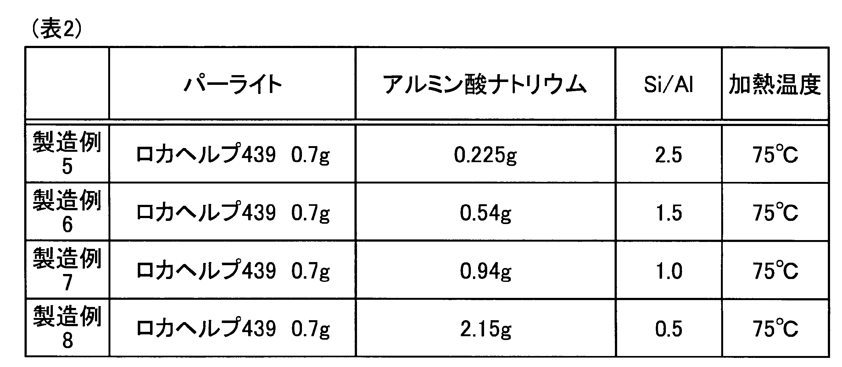
次に、本発明の実施例2について説明する。実施例2では、Si/Alおよび加熱温度の条件を表2に示す条件に変えたこと以外は、実施例1で説明した方法と同様にして、製造例5~8の供試体を作製した(表2参照)。具体的には、加熱温度を75℃に設定した。このようにして作製した製造例5~8の供試体に対して、実施例1と同様に、XRDによる結晶構造解析と、SEMによる組織観察を行った。XRDによる結晶構造解析の結果を図4に示す。なお、図4では、製造例7の実験結果の記載を省略している。
次に、本発明の実施例2について説明する。実施例2では、Si/Alおよび加熱温度の条件を表2に示す条件に変えたこと以外は、実施例1で説明した方法と同様にして、製造例5~8の供試体を作製した(表2参照)。具体的には、加熱温度を75℃に設定した。このようにして作製した製造例5~8の供試体に対して、実施例1と同様に、XRDによる結晶構造解析と、SEMによる組織観察を行った。XRDによる結晶構造解析の結果を図4に示す。なお、図4では、製造例7の実験結果の記載を省略している。
XRDによる結晶構造解析の結果から製造例5~8の供試体は、ゼオライトが形成されていることが確認された。また、55℃で合成した場合よりもX線の回折強度が高く、ゼオライトの結晶性が高くなることも確認された。また、製造例5の供試体では、LTA型およびFAU型のゼオライトが確認された。一方、製造例6~8の供試体では、LTA型のゼオライトが確認された。また、SEM観察の結果から、55℃で作製した場合と比較して、パーライトが少なくなり、ゼオライトが増加することが確認された。Si/Alが2.5の条件で作製された製造例5の供試体では、パーライトの量が特に少ないことが確認された。
(実施例3)
次に、本発明の実施例3について説明する。実施例3では、加熱温度の条件を45℃に変えたこと以外は、実施例1で説明した方法と同様にして、製造例9~12の供試体を作製した(表3参照)。これら製造例9~12の供試体に対して、実施例1と同様に、XRDによる結晶構造解析と、SEMによる組織観察を行った。XRDによる結晶構造解析の結果を図5に示す。
次に、本発明の実施例3について説明する。実施例3では、加熱温度の条件を45℃に変えたこと以外は、実施例1で説明した方法と同様にして、製造例9~12の供試体を作製した(表3参照)。これら製造例9~12の供試体に対して、実施例1と同様に、XRDによる結晶構造解析と、SEMによる組織観察を行った。XRDによる結晶構造解析の結果を図5に示す。

図5に示すように、XRDによる結晶構造解析の結果から、製造例9~12の供試体では、LTA型のゼオライトが形成されていることが確認された。なお、45℃の合成条件では、FAU型のゼオライトは確認されなかった。また、SEM観察の結果からも、パーライトの表面に微細なゼオライトが合成されていることが確認された。
以上の実施例1~3の結果から、加熱温度45℃~75℃の範囲では、ゼオライトの形成量および、パーライトとゼオライトの割合のバランスから、Si/Alが0.5以上1.5以下の範囲に設定することが好ましい。
(実施例4)
次に、本発明の実施例4について説明する。実施例4では、表面修飾パーライトを作製する際においてオートクレーブが必要か否かについて調べた。製造例13は、オートクレーブ容器を用いて、表4に示すSi/Alとなるようにし、その他は実施例1で説明した方法と同様にして表面修飾パーライトの供試体を作製した。製造例14は、オートクレーブ容器を使用せず、セラミックス容器に溶液を入れて、表4に示すSi/Alとなるようにし、その他は実施例1で説明した方法と同様にして表面修飾パーライトの供試体を作製した。製造例15は、1Lの樹脂容器に700mlの溶液となるように、表4に示すロカヘルプ439とアルミン酸ナトリウムとを水酸化ナトリウムに加え、その他は実施例1で説明した方法と同様にして表面修飾パーライトの供試体を作製した。
次に、本発明の実施例4について説明する。実施例4では、表面修飾パーライトを作製する際においてオートクレーブが必要か否かについて調べた。製造例13は、オートクレーブ容器を用いて、表4に示すSi/Alとなるようにし、その他は実施例1で説明した方法と同様にして表面修飾パーライトの供試体を作製した。製造例14は、オートクレーブ容器を使用せず、セラミックス容器に溶液を入れて、表4に示すSi/Alとなるようにし、その他は実施例1で説明した方法と同様にして表面修飾パーライトの供試体を作製した。製造例15は、1Lの樹脂容器に700mlの溶液となるように、表4に示すロカヘルプ439とアルミン酸ナトリウムとを水酸化ナトリウムに加え、その他は実施例1で説明した方法と同様にして表面修飾パーライトの供試体を作製した。

これら製造例13~15の供試体に対して、実施例1と同様に、XRDによる結晶構造解析と、SEMによる組織観察を行った。XRDによる結晶構造解析の結果を図6に示す。図6に示すように、製造例13~15の供試体において、LTA型のゼオライトが形成されていることが確認された。また、SEM観察の結果からも、パーライトの表面にゼオライトが形成されていることを確認した。この結果から、オートクレーブを使用しなくても、本製造例の表面修飾パーライトを製造できることが確認された。
(実施例5)
次に、本発明の実施例5について説明する。実施例5で、パーライトからゼオライトへの転化率と時間との関係を調べた。表5に示す条件で、製造例16~20の供試体を作製した。加熱時間は、24h~120hの範囲に設定した。
次に、本発明の実施例5について説明する。実施例5で、パーライトからゼオライトへの転化率と時間との関係を調べた。表5に示す条件で、製造例16~20の供試体を作製した。加熱時間は、24h~120hの範囲に設定した。
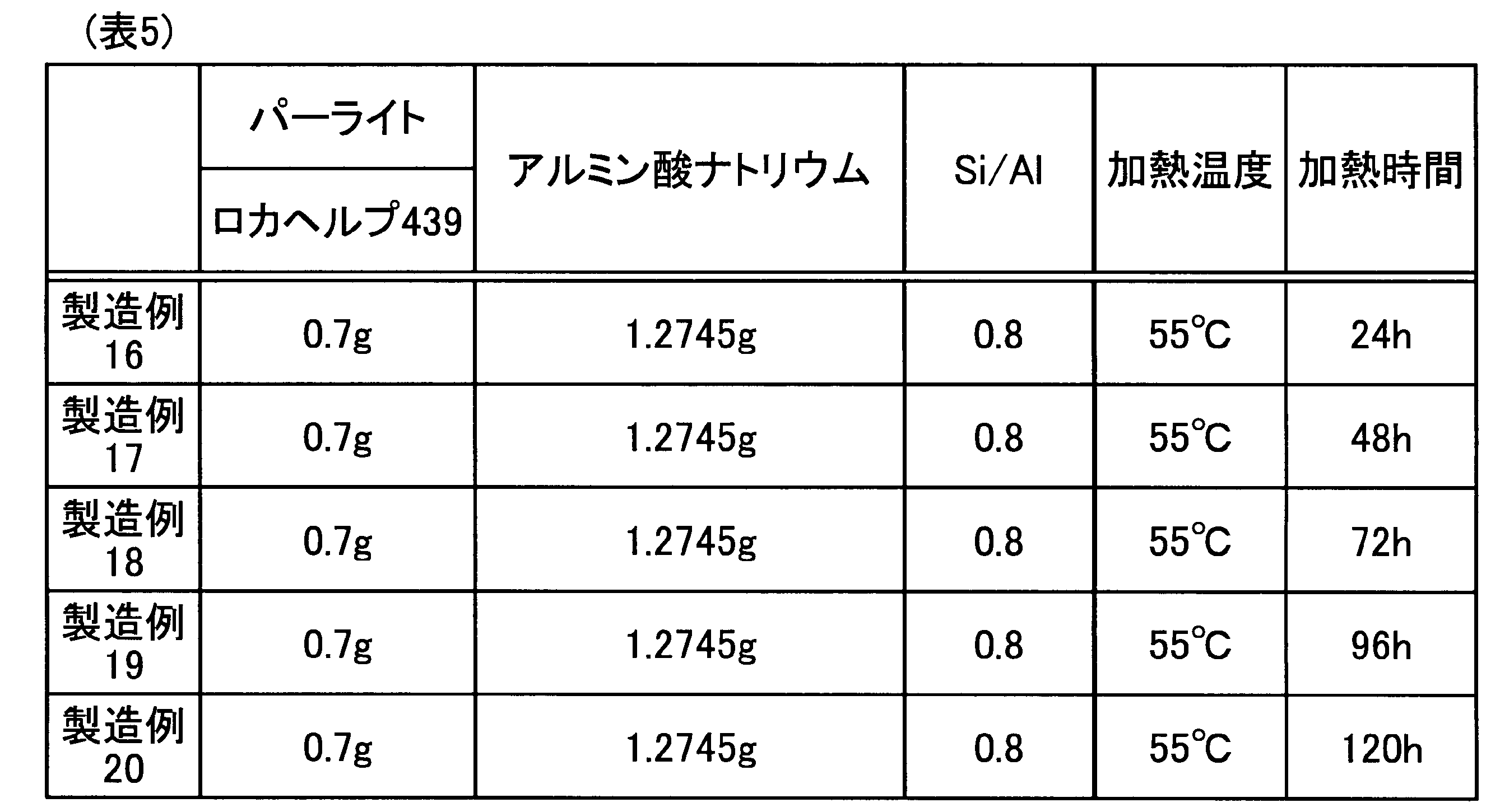
作製した供試体について、XRDによる結晶構造解析と、SEMによる組織観察を行った。また、蛍光X線分析により、表面修飾パーライト中におけるSiO2とAl2O3のmass%の割合を求め、さらにSiとAlのモル比Si/Alを算出した。この評価結果を、表6に示す。また、XRDによる結晶構造解析の結果を図7に示す。
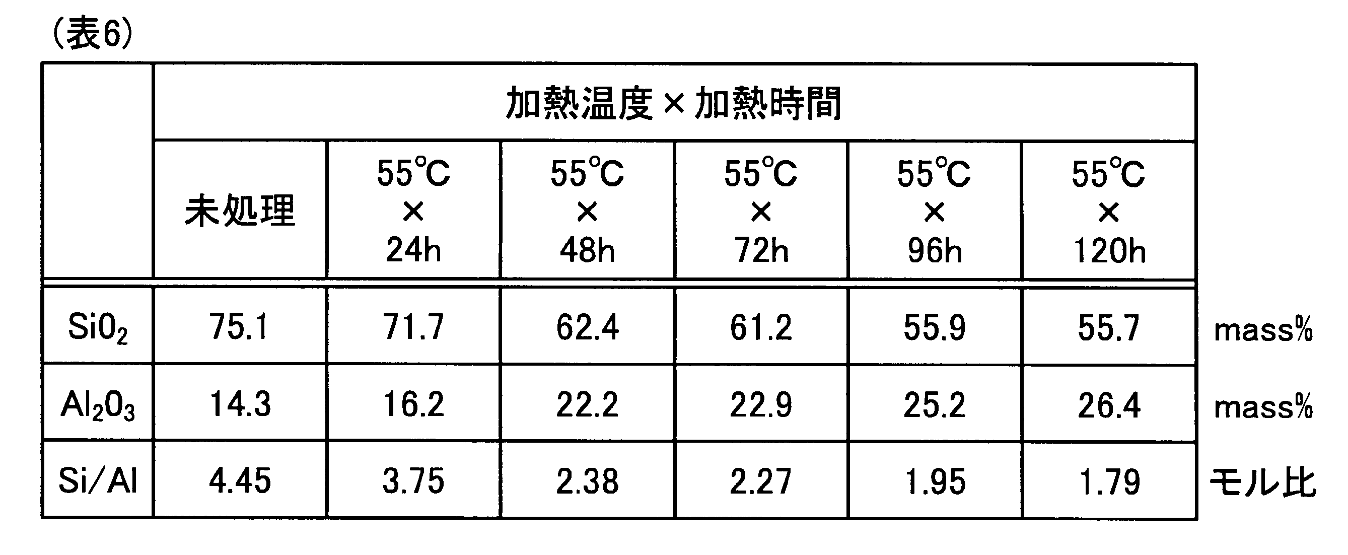
図7に示すように、加熱時間の増加とともに、LTA型のゼオライトのピークが高くなることが確認された。また、蛍光X線分析により得られたSi/Alの結果より、Si/Alが4.45以下1.79以上の範囲で組成が変化することを確認できた。
(実施例6)
次に、本発明の実施例6について説明する。実施例6では、表面修飾パーライトのイオン吸着試験を行った。イオン吸着試験は、Cd、Cu、Pb、Zn、Mn、Fe、Co、Ni、Al、Cr、Cs、およびSrの標準溶液(20ml、10ppm)の溶液を用意し、吸着剤として表7~表18に示すものを溶液に対して1wt%加え、1~12時間浸漬させた。その後、ろ過を行い、ろ液を回収し、ICP(Inductively Coupled Plasma)測定を行った。
次に、本発明の実施例6について説明する。実施例6では、表面修飾パーライトのイオン吸着試験を行った。イオン吸着試験は、Cd、Cu、Pb、Zn、Mn、Fe、Co、Ni、Al、Cr、Cs、およびSrの標準溶液(20ml、10ppm)の溶液を用意し、吸着剤として表7~表18に示すものを溶液に対して1wt%加え、1~12時間浸漬させた。その後、ろ過を行い、ろ液を回収し、ICP(Inductively Coupled Plasma)測定を行った。
なお、吸着剤として、具体的には以下のものを使用した。
試薬LTA型ゼオライト:ゼオラムA-4、粉末(東ソー株式会社製、市販品)
試薬FAU型ゼオライト:HSZ-300(320NAA)(東ソー株式会社製、市販品)
表面修飾パーライト(LTA型)として、実施例6では、製造例4で作製したものを使用した。また、図8に吸着試験前の表面修飾パーライトのSEM画像を示す。
試薬LTA型ゼオライト:ゼオラムA-4、粉末(東ソー株式会社製、市販品)
試薬FAU型ゼオライト:HSZ-300(320NAA)(東ソー株式会社製、市販品)
表面修飾パーライト(LTA型)として、実施例6では、製造例4で作製したものを使用した。また、図8に吸着試験前の表面修飾パーライトのSEM画像を示す。
測定結果を表7~表18に示す。なお、表7はCdイオン、表8はCuイオン、表9はPbイオン、表10はZnイオン、表11はMnイオン、表12はFeイオン、表13はCoイオン、表14はNiイオン、表15はAlイオン、表16はCrイオン、表17はCsイオン、および表18はSrイオンにおけるそれぞれの測定結果を示す。また、図9に吸着試験後の表面修飾パーライトのSEM観察結果を示す。
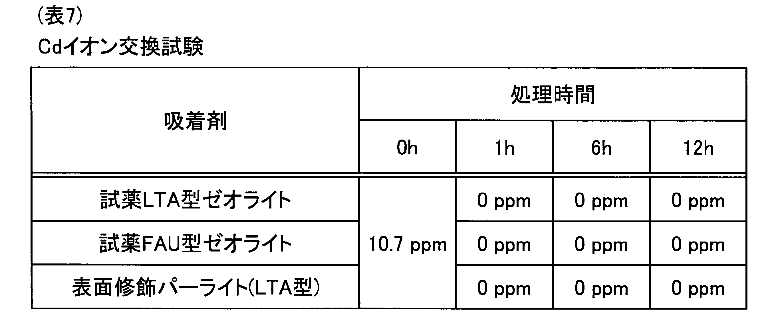
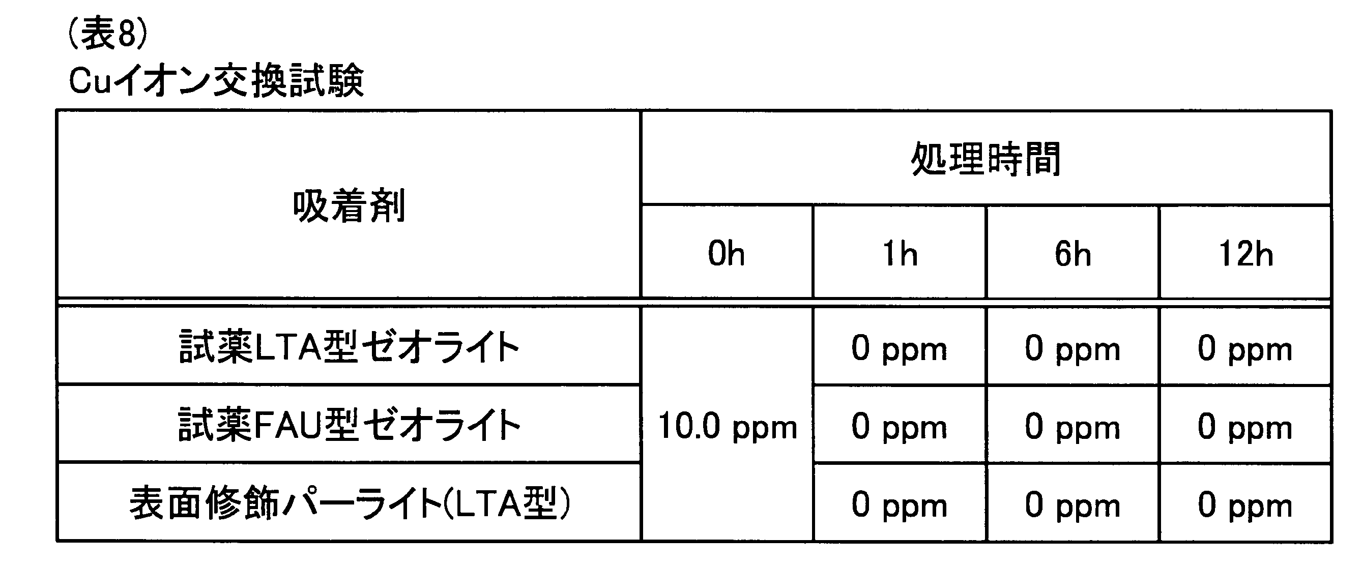


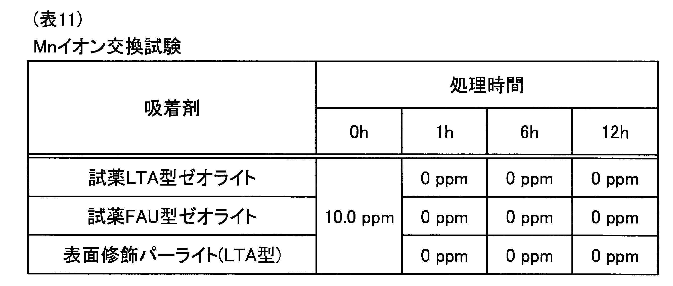


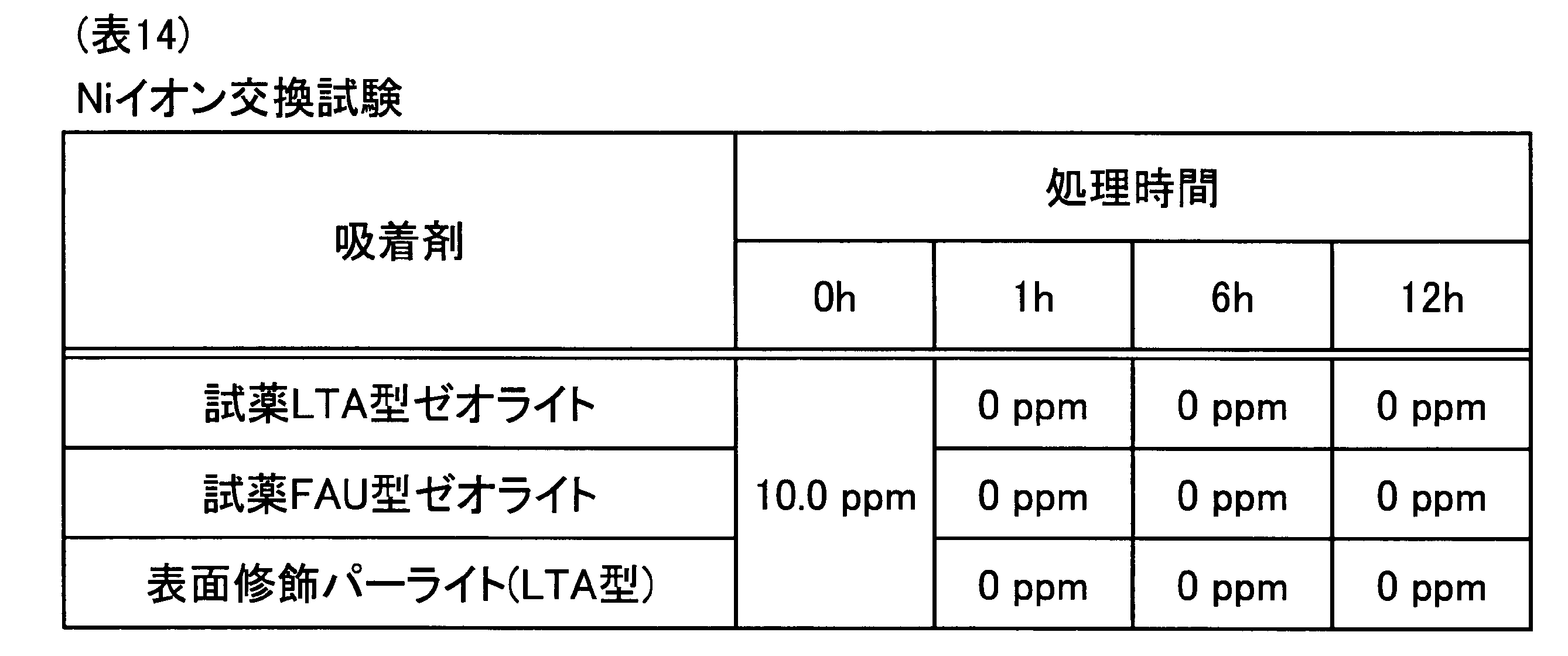

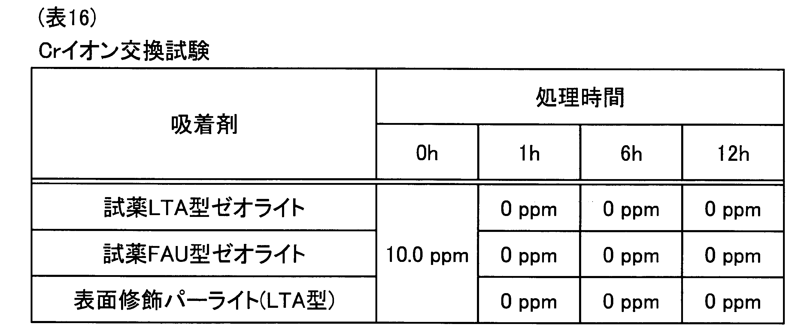


表7~表18に示すように、Cd、Cu、Pb、Zn、Mn、Fe、Co、Ni、Al、Cr、Cs、およびSrのイオンに対して、吸着特性が良好であることが確認された。また、本発明の表面修飾パーライトは、市販品のものと同様に吸着特性を有することが確認された。また、図8および図9に示す吸着試験前後のSEM画像から、吸着前後で表面修飾パーライトに変化がないことが確認された。
実施例6では、さらに、各種イオン(Al、Cr、Cu、Cd、Pb)を含有した鉱山排水を使用して、吸着試験を行った。吸着時間を10分と30分の2条件で行い、吸着剤と鉱山排水との割合が、10mg:10mlとなるようにして実験を行った。図10A~図10Eに、吸着時間10分の時の実験結果、図11A~図11Eに、吸着時間30分の時の実験結果を示す。なお、図10A~図10Eおよび図11A~図11Eは、それぞれ各種イオン(Al、Cr、Cu、Cd、Pb)に対する吸着試験に対応している。
図10A~図10Eおよび図11A~図11Eに示す鉱山排水を使用した実験結果より、本発明に係る表面修飾パーライトが、各種元素を吸着処理できることを確認した。また、処理時間10分と30分では大きな差がなく、10分でも十分に吸着できることを確認した。
すなわち、本発明の表面修飾パーライトは、水処理材として、水溶液中のAl、Cr、Mn、Fe、Co、Ni、Cu、Zn、Cd、Pb、Cs、およびSrからなる群から選ばれた少なくとも1種類の元素を吸着可能に構成される。
(実施例7)
次に、本発明の実施例7について説明する。実施例7では、表面修飾パーライトのケーキ比抵抗を測定した。まずケーキ比抵抗の測定方法について以下に説明する。
次に、本発明の実施例7について説明する。実施例7では、表面修飾パーライトのケーキ比抵抗を測定した。まずケーキ比抵抗の測定方法について以下に説明する。
まず、洗ビンに蒸留水を採り、温水器で予め30℃に加温しておく。次に、ビーカーをろ過器内にセットする。次に、ろ紙(No.2)をろ過器にクリップで固定する。二方コックを閉じて真空ポンプを起動し、負圧を200mmHgに調整する。次に、サンプル2gを300mlビーカーに量る。30℃に加温した蒸留水100mlを加えて撹拌し、ろ過器内に流し込む。このとき、ビーカー内に付着したサンプルは洗ビンで流し込む。次に、二方コックを不落、この時負圧を200mmHgになるようにする。ろ過器内の液面と形成されたケーキ面の差が5mm程度になったらろ過器内側に付着したサンプルを洗ビンにて洗い落とす。この操作を2回行った後、再び液面とケーキ面の差が5mm程度になったら、静かにケーキ面を荒らさないように蒸留水(30℃に加温)250mlをろ過器内に流し込む。ろ過器内にセットした300mlビーカーに溜まったろ過液が200mlより300ml間を通過する100mlのろ過時間θを測定する。ろ過終了後、二方コックを閉じ、ろ過器からケーキを取り出し、ケーキの厚さhcmを測定する。そして、以下の式により、ケーキ比抵抗aを算出する。
k(ろ過速度)=(√(100/θ/1.56))2×1.128
a(ケーキ比抵抗)=1/(k×γ)
ここで、γ(ケーキ嵩密度)は、ろ過前の助剤(表面修飾パーライト)の嵩密度である。
k(ろ過速度)=(√(100/θ/1.56))2×1.128
a(ケーキ比抵抗)=1/(k×γ)
ここで、γ(ケーキ嵩密度)は、ろ過前の助剤(表面修飾パーライト)の嵩密度である。
実施例7では、表面修飾パーライトとして、実施例5で作製した供試体を使用して、上記した方法によりケーキ比抵抗(平均比抵抗)aを測定する実験を行った。なお、ここでは、負圧(圧力)を変動させて実験データを取得した。また、比較のため、表面修飾をしていないロカヘルプ439のケーキ比抵抗を測定する実験も行った。この実験の結果を図12に示す。
図12に示すように、本実施例で作製した表面修飾パーライトは、ろ過機能を有していることが確認された。また、加熱時間によってゼオライトの形成量は増加しているが、ろ過機能には大きな差は見られないことが分かった。初期のパーライトの粒径を制御することでろ過特性を制御し、ゼオライトの合成量を制御することで吸着特性を制御することができる。
(実施例8)
次に、本発明の実施例8について説明する。実施例8においては、上述した実施例1による表面修飾パーライトの製造方法に基づいて製造された製造例3の表面修飾パーライトの粉末に対して、超音波の照射前後における粒径分布を測定した。図13は、超音波の照射前後における粒径分布を測定したグラフである。ここで、粒径分布の測定装置としては、レーザー回折・散乱式粒子径分布測定装置である「マイクロトラックMT3000EXII」(マイクロトラック・ベル株式会社製)を用い、粒径分布の測定は、粒径分布の測定装置に付属した超音波装置を作動させながら行った。
次に、本発明の実施例8について説明する。実施例8においては、上述した実施例1による表面修飾パーライトの製造方法に基づいて製造された製造例3の表面修飾パーライトの粉末に対して、超音波の照射前後における粒径分布を測定した。図13は、超音波の照射前後における粒径分布を測定したグラフである。ここで、粒径分布の測定装置としては、レーザー回折・散乱式粒子径分布測定装置である「マイクロトラックMT3000EXII」(マイクロトラック・ベル株式会社製)を用い、粒径分布の測定は、粒径分布の測定装置に付属した超音波装置を作動させながら行った。
図13に示すように、実施例8による表面修飾パーライトにおいて、表面修飾パーライトの粉末に対して超音波を照射する前(0[s]:一点鎖線)では、粒径分布のピークが約20μm程度の粒径で1つ存在することが分かる。ここで、実施例8による表面修飾パーライトにおいては、20μm程度の粒径が全体量の約5.2%存在している(以下、頻度が約5.2%である等という)。なお、この実施例8において用いたパーライトの粒径分布は、ゼオライトを含まない状態において、図13に示す超音波を照射する前の粒径分布と略等しい粒径分布を有していた。
また、図13から、表面修飾パーライトにおいて、第1所定時間としての60秒間(1分間)超音波を照射した後(60[s]:破線)においても、粒径分布のピークが、20μm程度の粒径で1つ存在していることが分かる。すなわち、超音波を照射する前と超音波を60秒間照射した後とにおいて、粒径分布のピークとなる粒径が略等しいことが分かる。なお、60秒間の超音波の照射後においては、約20μmの粒径の頻度は約5.0%である。さらに、表面修飾パーライトにおいて、第1所定時間よりも長い第2所定時間としての300秒(5分間)超音波を照射した後(300[s]:実線)における粒径分布も同様に、粒径分布のピークが20μm程度の粒径で1つ存在していることが分かる。
すなわち、図13から、表面修飾パーライトにおいては、超音波の照射前、超音波を60秒間照射した後、および超音波を300秒間照射した後において、粒径分布のピークとなる粒径が互いに略等しいことが分かる。これは、表面修飾パーライトは、パーライトとゼオライトとが分離することなく存在していることに起因すると考えられる。すなわち、パーライトとゼオライトとの間で、パーライトの非晶質構造からゼオライトの結晶構造へ連続的に変化している部分を有することによって、ゼオライトとパーライトとが結晶構造として結合されているためであると考えられる。
そこで、実施例8による表面修飾パーライトと比較するために、ゼオライトとパーライトとを単に混合させた状態の混合粉末に対して、超音波の照射前後の粒径分布を測定した。図14は、パーライトを含まずゼオライトから構成される粉末に対して、超音波の照射前後における粒径分布を測定したグラフである。図15は、実施例8による表面修飾パーライトと比較する比較例として、パーライトの粉末とゼオライトの粉末とを単に混合させた混合粉末に対して、超音波の照射前後における粒径分布を測定したグラフである。なお、パーライトおよびゼオライトは、表面修飾パーライトの製造に用いた材料と同様の材料を用いる。
図14に示すように、ゼオライトの粉末に対して超音波を照射する前(0[s]:一点鎖線)においては、1~2μm程度および20μm程度の2つの粒径において、粒径分布のピークが存在することが分かる。このゼオライトの粉末においては、1~2μm程度の粒径の頻度が約2.5%、約20μm程度の粒径の頻度が約6.5%であることが分かる。
また、ゼオライトの粉末に対して超音波を60秒間(1分間)照射した後(60[s]:破線)においても、約1~2μm程度および約20μm程度の2つの粒径において、粒径分布のピークが存在する。そして、これらの2つの粒径分布のピークが、超音波の照射前の2つの粒径分布のピーク(図14中、一点鎖線)と、それぞれ略等しいことが分かる。なお、60秒間の超音波の照射後において、約1~2μmの粒径の頻度が約2.5%、約20μmの粒径の頻度が約6.0%である。さらに、ゼオライトの粉末に対して超音波を300秒(5分間)照射した後(300[s]:実線)における粒径分布においても同様に、約1~2μm程度で頻度が約3.0%、および約20μm程度で頻度が約4.5%の2つの粒径分布のピークが存在することが分かる。すなわち、ゼオライトのみから構成された粉末においては、粒径分布の2つのピークとなる粒径が、超音波の照射前後において、それぞれ略等しいことが分かる。
そして、パーライトの粉末と、図14に示す粒径分布を有するゼオライトの粉末とを単に混合させた混合粉末の場合、図15に示す粒径分布が得られる。すなわち、図15に示すように、混合粉末に対して、超音波を照射する前(0[s]:一点鎖線)においては、パーライトの粒径分布に起因して、約20μm程度の粒径において1つのピークが存在することが分かる。この混合粉末においては、20μm程度の粒径の頻度が約5.7%であることが分かる。
そして、混合粉末に対して超音波を60秒間(1分間)照射した後(60[s]:破線)においては、粒径分布のピークが、5μm程度の粒径でさらに現れることが分かる。なお、超音波の照射前と同様に、粒径分布のピークが20μm程度の粒径においても存在している。さらに、混合粉末に対して超音波を300秒(5分間)照射した後(300[s]:実線)における粒径分布においては、粒径分布のピークは、約1μmで頻度が約2.3%、および約20μmで頻度が約4.8%の2つ現れることが分かる。すなわち、混合粉末に対する超音波の照射時間を長くするに従って、図14に示すゼオライトの粉末の粒径分布に近づいていくことが分かる。これは、混合粉末に対する超音波の照射を継続することによって、ゼオライトとパーライトとが分離されることに起因すると考えられる。
以上から、パーライトとゼオライトとを混合させた混合粉末では、パーライトの表面にゼオライトが付着するのみで、超音波を照射することで容易に分離してしまい、表面修飾パーライトが得られないことが確認された。すなわち、図13~図15から、表面修飾パーライトは、ゼオライトとパーライトとを単に混合させた混合粉末とは異なり、パーライトにゼオライトが結合された構造を有することが確認された。
一方、上述した実施形態による表面修飾パーライトの製造方法によって得られるゼオライト粒子は、後述するように、パーライト粒子よりも小さく、パーライト粒子の表面部分に生成している(図16、図18参照)。このゼオライト粒子は、パーライト粒子の表面部分と連続的に変化している部分を有することによって、パーライト粒子がゼオライト粒子と強固に結合することが可能となり、超音波等を照射してもパーライト粒子から容易に分離しない。そのため、超音波を付加しながら行う粒度分布測定においても、ゼオライト粒子に依拠する微粒子部分の粒度ピークが、パーライト粒子に依拠する粒度ピークから分離しないことが分かる。これにより、パーライト粒子自身が保有するろ過助剤としての性能を長期間維持することも可能になると考えられる。
その上で、本発明者は、実施例8による表面修飾パーライトの粉末に対して、ナノスケール部位での構造解析を目的として、透過型電子顕微鏡(TEM:Transmission Electron Microscope)を用いた制限視野電子回折(SAED:Selected Area Electron Diffraction)法による解析を行った。ここで、解析を行う表面修飾パーライトの試料としては、微量の試料粉末をエタノール中で超音波分散させた後、非晶質の炭素支持膜上に滴下させて乾燥させたものを用いた。なお、ゼオライトの結晶は、電子線に対して耐性が低く容易に非晶質化するため、観察には、低電子線量観察手法を用いた。また、TEM観察装置としては、FEI社製TITAN(登録商標)を用い、加速電圧を300kVとして、収差補正器を調整して球面収差係数を±10μm以内にした。図16Aは、実施例8において製造された表面修飾パーライトのTEM画像の例を示す図であり、図16Bおよび図16Cはそれぞれ、図16Aの囲み部B,Cにおける電子線回折像の例を示す図である。図17は、炭素支持膜に形成された表面修飾パーライトを示すTEM画像の例を示す図である。
上述したTEMを用いた解析の結果、図16Aに示すように、不定形の材料の表面に直方体状の部位が形成されていることが確認された。直方体状の部位は、ゼオライト(LTA型ゼオライト)の特徴となる部位である。そこで、本発明者は、制限視野絞りによって、直方体状の部位部分(囲み部B)および不定形の部位部分(囲み部C)をそれぞれ選択し、電子回折パターンを取得して、これらの部分の構造を確認した。その結果、図16Bに示すように、直方体状の部位部分においては結晶構造が存在し、その結晶の周期は立方晶のLTA構造に帰属していることが確認された。また、図16Cに示すように、不定形の部位部分における電子回折パターンは、非晶質に特有の、回折ピークのないハローパターンになっていることが確認された。なお、上述したように、観察には低電子線量観察手法を用い、極めて低いドーズ量での解析を行っている。これにより、図16Cに示すTEM画像は、不定形の部位部分が電子線の照射による損傷で非晶質化されたのではなく、不定形の材料そのものが本来非晶質であり、不定形の部位がパーライトであることを示している。以上から、TEMを用いた観察によって、不定形の非晶質部分上に、直方体状でLTA構造のLTA型のゼオライトが形成されていることが確認された。
また、本発明者は、炭素支持膜上に形成された表面修飾パーライトにおいて、パーライトとゼオライトとの間の結晶構造を観察した。その結果を図17に示す。図17からは、囲み部分内において、炭素支持膜上のパーライトからゼオライトに向かって、濃淡が淡い部分から濃い部分に変化していることが分かる。これは、炭素支持膜上の表面修飾パーライトの結晶構造が、非晶質構造のパーライトから結晶構造のゼオライトに連続的に変化している部分を有することを示している。すなわち、図17中の囲み部内において、パーライトにおける非晶質構造が、囲み部内の矢印方向に向かって徐々に結晶構造に変化して、最終的にゼオライトの結晶構造となっていることが確認できる。これにより、表面修飾パーライトにおいて、パーライトの非晶質構造からゼオライトの結晶構造に連続的に変化し、この連続的に変化した部分(図17中、囲み部分)において、パーライトとゼオライトとが化学的に強固に結合されていることが確認された。
パーライトとゼオライトとが化学的に強固に結合されていることにより、上述したように、表面修飾パーライトに超音波を所定時間以上照射した場合であっても、表面修飾パーライトからゼオライトが分離することがない。そのため、図13に示すように、パーライトの粉末に対して超音波を所定時間以上照射した後の粒径分布のピークとなる粒径は、超音波を照射する前から移動することなく、パーライトの粉末における粒径分布のピークとなる粒径と略等しくなる。なお、表面修飾パーライトを構成するパーライトの粒径分布のピークが複数存在する場合においても、表面修飾パーライトの粒径分布におけるそれぞれのピークとなる粒径は、超音波を所定時間以上照射した後であっても、ほとんど移動することがない。すなわち、表面修飾パーライトに対して、超音波を所定時間以上照射した場合であっても、粒径分布がピークとなるそれぞれの粒径は、それぞれ超音波の照射前後において略等しくなる。
(実施例9)
次に、本発明の実施例9について説明する。図18は、生成された表面修飾パーライトにおける、水酸化ナトリウムの濃度ごとに、2000倍、5000倍、および15000倍に拡大したSEM画像の例を示す図である。
次に、本発明の実施例9について説明する。図18は、生成された表面修飾パーライトにおける、水酸化ナトリウムの濃度ごとに、2000倍、5000倍、および15000倍に拡大したSEM画像の例を示す図である。
すなわち、本発明者は、上述した表面修飾パーライトの製造方法において用いるアルカリ金属水酸化物の水溶液としてのNaOH水溶液の濃度を、0.3mol/Lから1.0mol/Lの範囲で変化させて、得られた表面修飾パーライトのSEM画像を解析した。なお、表面修飾パーライトの合成条件は、実施例1の製造例3と同様である。その結果、図18に示すように、NaOH水溶液の濃度が、0.3mol/L以上1.0mol/L以下であれば、不定形の部位であるパーライトの表面に直方体状の部位であるゼオライトの結晶が形成されることが確認された。また、NaOH水溶液の濃度が低下するほど、パーライト(不定形の部位)の表面に形成されるゼオライトの結晶(直方体状の部位)の大きさが小さくなって、結晶性が低下し、生成数も低減することが確認された。ゼオライトの結晶性および生成数を考慮すると、NaOH水溶液の濃度は、0.3mol/L以上が好ましく、0.5mol/Lより大きいのがより好ましく、または0.8mol/L以下が好ましい。
(実施例10)
次に、本発明の実施例10について説明する。図19は、循環吸着によるセシウム(Cs)の吸着試験の方法を説明するためのブロック図である。図19に示すように、吸着試験を行う試験装置1は、容器10と、チューブポンプ20と、吸着カラム30とを備える。容器10は、セシウム(Cs)溶液11を貯留可能に構成されている。チューブポンプ20は、従来公知のチューブポンプである。すなわち、チューブポンプ20は、弾性チューブが押し潰されてチューブ内部の液体が押し出されるとともに、復元力によって元の形状に戻る際に液体を吸引する動作を連続的に行うことによって、吸引および吐出を行うポンプである。
次に、本発明の実施例10について説明する。図19は、循環吸着によるセシウム(Cs)の吸着試験の方法を説明するためのブロック図である。図19に示すように、吸着試験を行う試験装置1は、容器10と、チューブポンプ20と、吸着カラム30とを備える。容器10は、セシウム(Cs)溶液11を貯留可能に構成されている。チューブポンプ20は、従来公知のチューブポンプである。すなわち、チューブポンプ20は、弾性チューブが押し潰されてチューブ内部の液体が押し出されるとともに、復元力によって元の形状に戻る際に液体を吸引する動作を連続的に行うことによって、吸引および吐出を行うポンプである。
吸着カラム30は、カラムケース31内に、下層から順に、ガラス繊維ろ紙32、吸着剤33、およびガラスビーズ34が積層されて構成されている。ここで、ガラスビーズ34は、吸着剤33による吸着対象物質の吸着に寄与するものではなく、設けないことも可能である。この実施例10においてガラスビーズ34は、吸着剤33の安定性を考慮して設けられている。ここで、吸着剤33の質量としては1gとした。カラムケース31の上部から、Cs溶液を流入可能に構成されているとともに、カラムケース31の下部から吸着後のCs溶液を流出可能に構成されている。
試験装置1において、容器10からチューブポンプ20によって吸引されたCs溶液11は、吸着カラム30に供給される。吸着カラム30内における吸着剤33によって、Cs溶液中のCsの一部が吸着される。Csの一部が吸着されたCs溶液は吸着カラム30から容器10に戻される。以上によって、試験装置1によってCs溶液が循環されて吸着カラム30を通過する。以下、試験装置1による吸着試験を、循環吸着試験という。
本発明者は、Cs溶液として非放射性のセシウムを含む非放射性Cs溶液に対して、吸着カラム30内の吸着剤33を種々の材料に変えて吸着実験を行った。非放射性Cs溶液の濃度は0.128g/100ml=1000ppm、溶液量は100mlとする。また、吸着剤33としては、本発明による表面修飾パーライト、従来のパーライトであるロカヘルプ439、およびゼオライト試薬である試薬LTA型ゼオライト(ゼオラムA-4、東ソー株式会社製)をそれぞれ1gの量で用いた。また、測定装置としては、液体クロマトグラフィを用いた。
図20A、図20B、および図20Cはそれぞれ、Cs溶液を1L分、2L分、および3L分循環させた場合の実験結果である。ここで、循環吸着試験において、溶液を1L分循環させるとは、容量が100mlの溶液を吸着カラム30に10回通過させることを意味する。実施例10による循環吸着試験において、溶液を1L分循環させるのに要する時間は、吸着剤33が表面修飾パーライトの場合に約13分間、パーライトの場合に約15分、ゼオライト試薬の場合に約18分であった。
図20Aに示すように、非放射性Cs溶液を1L分循環させた後のCs濃度は、吸着剤33が表面修飾パーライトの場合に207ppm、パーライトの場合に986ppm、ゼオライト試薬の場合に52ppmになることが分かった。なお、未処理とは、非放射性Cs溶液に対して循環吸着試験を行っていない場合を意味する。同様に、図20Bに示すように、非放射性Cs溶液を2L分循環させた後のCs濃度は、吸着剤33が表面修飾パーライトの場合に242ppm、パーライトの場合に977ppm、ゼオライト試薬の場合に98ppmになることが分かった。さらに、図20Cに示すように、非放射性Cs溶液を3L分循環させた後のCs濃度は、吸着剤33が表面修飾パーライトの場合に241ppm、パーライトの場合に983ppm、ゼオライト試薬の場合に58ppmになることが分かった。
図20A~20Cに示すように、吸着カラム30における吸着剤33として、本発明による表面修飾パーライトを用いた場合においても、吸着対象物質を吸着できることが確認された。すなわち、上述した実施例6における溶液への吸着剤の添加、および溶液のろ過処理という回収方法以外にも、吸着カラム30を用いた回収方法も可能であることが確認された。さらに、本発明者が循環吸着試験における吸着カラム30内の目詰まりを確認したところ、ろ過助剤の効果によって目詰まりが生じにくく、安定した吸着処理が可能であることが確認された。また、図20A~20Cに示す実験結果においては、本発明による表面修飾パーライトの吸着能が、ゼオライト試薬に比して劣る結果となっている。これは、上述した循環吸着試験において用いたゼオライト試薬に対して、本発明による表面修飾パーライトに析出しているゼオライトの量が少ないことが原因である。
なお、本発明者の知見によれば、吸着試験に用いたゼオライトのLTA型に帰属するピークの強度は、ゼオライト試薬の約1/2である。これにより、LTA型ゼオライトの析出量は、ゼオライト試薬の析出量の約1/2となるので、上述した実施例10における循環吸着試験の実験結果において、本発明による表面修飾パーライトの吸着能が、ゼオライト試薬に比して劣る結果として現れている。また、本発明者の知見によれば、パーライトの表面に析出させるゼオライトの量については、合成を行う際の各種条件の設定によって変化させることが可能である。そのため、パーライトの表面に析出させるゼオライトの量は、浄化する対象の物質(浄化対象物質)や、液体の粘性などの特性に応じて調整することが可能である。
さらに、吸着対象物質を含む溶液に吸着剤を添加した後に、ろ過処理を行った回収する回収方法の場合、工業的な実用化を考慮すると、シックナーやろ過器などが必要となり大型の設備が必要になる。さらに、実際に工業的に実用化する場合、吸着剤の量を増加させる必要が生じる。この場合、吸着剤の量の増加に伴ってろ過性能の差が大きくなり、ろ過が困難になったり、ポンプの電力の消費量が増加したり、大型シックナーが必要になったりする。これに対し、吸着対象物質を除去する装置として、吸着カラム30を備えた吸着装置とした場合、シックナーやろ過器などが不要になるため、吸着やろ過のための大型の設備が不要になるという効果を奏することができる。
(実施例11)
次に、本発明の実施例11について説明する。実施例11においては、非放射性Cs溶液を静置させて吸着試験を行う。すなわち、非放射性Cs溶液に吸着剤を添加した後、シリンジを用いて上澄み溶液を回収液として回収する。その後、得られた回収溶液をメンブレンフィルターによってろ過処理することにより、吸着対象物質が除去されたろ液を得る。以下、この回収方法による吸着試験を、静置吸着試験という。
次に、本発明の実施例11について説明する。実施例11においては、非放射性Cs溶液を静置させて吸着試験を行う。すなわち、非放射性Cs溶液に吸着剤を添加した後、シリンジを用いて上澄み溶液を回収液として回収する。その後、得られた回収溶液をメンブレンフィルターによってろ過処理することにより、吸着対象物質が除去されたろ液を得る。以下、この回収方法による吸着試験を、静置吸着試験という。
本発明者は、Cs溶液として非放射性のセシウムを含む非放射性Cs溶液に対して、吸着剤を種々の材料に変えて静置吸着実験を行った。なお、非放射性Cs溶液の濃度は、実施例10と同様に、0.128g/100ml=1000ppmとする。吸着剤としては、本発明による表面修飾パーライト、従来のパーライトであるロカヘルプ439、およびゼオライト試薬である試薬LTA型ゼオライト(ゼオラムA-4、東ソー株式会社製)をそれぞれ1gの量で用いた。
図21A、図21B、および図21Cはそれぞれ、Cs溶液に吸着剤を添加した後に、0時間静置、1時間静置、および24時間静置させた場合の実験結果である。なお、静置吸着試験において0時間静置させる場合とは、非放射性Cs溶液に吸着剤を添加した直後に、回収液をろ過処理することを意味する。
図21Aに示すように、非放射性Cs溶液に吸着剤を添加して0時間静置させた後のCs濃度は、吸着剤が表面修飾パーライトの場合に252ppm、パーライトの場合に1000ppm、ゼオライト試薬の場合に68ppmになることが分かった。同様に、図21Bに示すように、非放射性Cs溶液に吸着剤を添加して1時間静置させた後のCs濃度は、吸着剤が表面修飾パーライトの場合に257ppm、パーライトの場合に1000ppm、ゼオライト試薬の場合に70ppmになることが分かった。さらに、図21Cに示すように、非放射性Cs溶液に吸着剤を添加して24時間静置させた後のCs濃度は、吸着剤が表面修飾パーライトの場合に261ppm、パーライトの場合に1000ppm、ゼオライト試薬の場合に72ppmになることが分かった。
(実施例12)
次に、本発明の実施例12について説明する。実施例12において使用する試験装置として、実施例10における試験装置1を用いる。実施例12においては、Cs溶液として放射性Cs溶液を用い、吸着カラム30内の吸着剤33を種々の材料に変えて吸着実験を行った。放射性Cs溶液中のCsの量は600Bq/kg、溶液量は100mlとする。また、吸着剤33としては、実施例10におけると同様に、本発明による表面修飾パーライト、従来のパーライトであるロカヘルプ439、およびゼオライト試薬である試薬LTA型ゼオライト(ゼオラムA-4、東ソー株式会社製)をそれぞれ1gの量で用いた。また、測定装置としては、ゲルマニウム半導体検出器を用いた。
次に、本発明の実施例12について説明する。実施例12において使用する試験装置として、実施例10における試験装置1を用いる。実施例12においては、Cs溶液として放射性Cs溶液を用い、吸着カラム30内の吸着剤33を種々の材料に変えて吸着実験を行った。放射性Cs溶液中のCsの量は600Bq/kg、溶液量は100mlとする。また、吸着剤33としては、実施例10におけると同様に、本発明による表面修飾パーライト、従来のパーライトであるロカヘルプ439、およびゼオライト試薬である試薬LTA型ゼオライト(ゼオラムA-4、東ソー株式会社製)をそれぞれ1gの量で用いた。また、測定装置としては、ゲルマニウム半導体検出器を用いた。
図22は、Cs溶液を1L分循環させた場合の実験結果である。実施例12による循環吸着試験において、Cs溶液を1L分循環させるのに要する時間は、実施例10と同様、吸着剤33が表面修飾パーライトの場合に約13分間、パーライトの場合に約15分、ゼオライト試薬の場合に約18分であった。
図22に示すように、放射性Cs溶液を1L分循環させた後の放射能量は、吸着剤33が表面修飾パーライトの場合に3.7Bq/kg、パーライトの場合に81Bq/kg、ゼオライト試薬の場合に2Bq/kgになることが分かった。なお、未処理とは、放射性Cs溶液に対して循環吸着試験を行っていない場合を意味する。この場合、放射能量は、600Bq/kgである。
図22に示すように、吸着カラム30における吸着剤33として、本発明による表面修飾パーライトを用いた場合においても、吸着対象物質を吸着できることが確認された。さらに、放射性Csの含有濃度は、実施例10において用いた非放射性Cs溶液の濃度に比して極めて低く、いわゆる極希薄系である。このような極希薄系の溶液においても本発明による表面修飾パーライトによる吸着が可能となる。さらに、実施例10と同様の効果を得ることができる。すなわち、本発明による表面修飾パーライトを用いれば、溶液への吸着剤の添加、および溶液のろ過処理という回収方法以外にも、吸着カラム30を用いた回収方法も可能であることが確認された。
(実施例13)
次に、本発明の実施例13について説明する。実施例13においては、実施例11と同様にして、放射性Cs溶液を静置させて吸着試験を行う。すなわち、放射性Cs溶液に吸着剤を添加した後、シリンジを用いて上澄み溶液を回収液として回収する。その後、得られた回収溶液をメンブレンフィルターによってろ過処理することにより、吸着対象物質が除去されたろ液を得る。
次に、本発明の実施例13について説明する。実施例13においては、実施例11と同様にして、放射性Cs溶液を静置させて吸着試験を行う。すなわち、放射性Cs溶液に吸着剤を添加した後、シリンジを用いて上澄み溶液を回収液として回収する。その後、得られた回収溶液をメンブレンフィルターによってろ過処理することにより、吸着対象物質が除去されたろ液を得る。
本発明者は、放射性Cs溶液に対して吸着剤を種々の材料に変えて静置吸着実験を行った。なお、放射性Cs溶液中の放射能量は、実施例12と同様に600Bq/kgとする。吸着剤としては、本発明による表面修飾パーライト、従来のパーライトであるロカヘルプ439、およびゼオライト試薬である試薬LTA型ゼオライト(ゼオラムA-4、東ソー株式会社製)をそれぞれ1gの量で用いた。
図23A、図23B、および図23Cはそれぞれ、放射性Cs溶液に吸着剤を添加した後に、0時間静置、1時間静置、および24時間静置させた場合の実験結果である。図23Aに示すように、放射性Cs溶液に吸着剤を添加して0時間静置させた後の放射能量は、吸着剤が表面修飾パーライトの場合に8.8Bq/kg、パーライトの場合に17Bq/kg、ゼオライト試薬の場合に2Bq/kgになることが分かった。同様に、図23Bに示すように、放射性Cs溶液に吸着剤を添加して1時間静置させた後の放射能量は、吸着剤が表面修飾パーライトの場合に9.1Bq/kg、パーライトの場合に10Bq/kg、ゼオライト試薬の場合に3.5Bq/kgになることが分かった。未処理の場合には、600Bq/kgである。さらに、図23Cに示すように、放射性Cs溶液に吸着剤を添加して24時間静置させた後の放射能量は、吸着剤が表面修飾パーライトの場合に12Bq/kg、パーライトの場合に36Bq/kg、ゼオライト試薬の場合に4Bq/kgになることが分かった。なお、未処理の場合においても、24時間静置させた後に590Bq/kgまで低減していることが確認された。
以上、本発明の実施形態について具体的に説明したが、本発明は、上述した実施形態に限定されるものではなく、本発明の技術的思想に基づく各種の変形が可能である。例えば、上述の実施形態において挙げた数値はあくまでも例に過ぎず、必要に応じてこれと異なる数値を用いても良い。また、上述の実施形態により本発明が限定されるものではない。上述した各構成要素を適宜組み合わせて構成したものも本発明に含まれる。また、さらなる効果や変形例は、当業者によって容易に導き出すことができる。
以上のように、本発明に係るパーライトおよびその製造方法、ならびに水処理方法および水処理材は、排水等から浄水を得るためのろ過に好適に用いられる。
1 試験装置
10 容器
11 Cs溶液
20 チューブポンプ
30 吸着カラム
31 カラムケース
32 ガラス繊維ろ紙
33 吸着剤
34 ガラスビーズ
10 容器
11 Cs溶液
20 チューブポンプ
30 吸着カラム
31 カラムケース
32 ガラス繊維ろ紙
33 吸着剤
34 ガラスビーズ
Claims (7)
- ゼオライトが形成された構造を有するパーライトであって、
前記パーライトと前記ゼオライトとの間で、前記パーライトの非晶質構造から前記ゼオライトの結晶構造へ連続的に変化している部分を有する
ことを特徴とするパーライト。 - ゼオライトが形成された構造を有するパーライトであって、
前記パーライトの粉末に対して超音波を所定時間以上照射した後における前記パーライトの粉末の粒径分布の少なくとも一つのピークとなる粒径が、前記超音波を照射する前の前記パーライトの粉末における粒径分布の少なくとも一つのピークとなる粒径とそれぞれ略等しい
ことを特徴とするパーライト。 - 前記パーライトの粉末に対して前記超音波を第1所定時間照射させた後における粒径分布の少なくとも一つのピークと、前記パーライトの粉末に対して前記超音波を前記第1所定時間より長い第2所定時間以上照射させた後における粒径分布の少なくとも一つのピークとが、それぞれ略等しいことを特徴とする請求項2に記載のパーライト。
- アルミニウム塩が溶解されたアルカリ金属水酸化物の水溶液に、パーライトを投入して混合させる調製工程と、
前記調製工程で得られた溶液を加熱する加熱工程と、
を含むことを特徴とするパーライトの製造方法。 - 前記アルカリ金属水酸化物の水溶液の濃度が、0.3mol/L以上1.0mol/L以下であることを特徴とする請求項4に記載のパーライトの製造方法。
- 請求項1~3のいずれか1項に記載のパーライトを用いて、
水溶液中のAl、Cr、Mn、Fe、Co、Ni、Cu、Zn、Cd、Pb、Cs、およびSrからなる群から選ばれた少なくとも1種類の元素を吸着処理する
ことを特徴とする水処理方法。 - 請求項1~3のいずれか1項に記載のパーライトを含む水処理材であって、
水溶液中のAl、Cr、Mn、Fe、Co、Ni、Cu、Zn、Cd、Pb、Cs、およびSrからなる群から選ばれた少なくとも1種類の元素を吸着可能に構成されている
ことを特徴とする水処理材。
Priority Applications (2)
| Application Number | Priority Date | Filing Date | Title |
|---|---|---|---|
| CN201780081196.3A CN110114312B (zh) | 2016-12-28 | 2017-12-26 | 珍珠岩及其制造方法、以及水处理方法及水处理材料 |
| JP2018559488A JPWO2018124018A1 (ja) | 2016-12-28 | 2017-12-26 | パーライトおよびその製造方法、ならびに水処理方法および水処理材 |
Applications Claiming Priority (2)
| Application Number | Priority Date | Filing Date | Title |
|---|---|---|---|
| JP2016-256580 | 2016-12-28 | ||
| JP2016256580 | 2016-12-28 |
Publications (1)
| Publication Number | Publication Date |
|---|---|
| WO2018124018A1 true WO2018124018A1 (ja) | 2018-07-05 |
Family
ID=62711075
Family Applications (1)
| Application Number | Title | Priority Date | Filing Date |
|---|---|---|---|
| PCT/JP2017/046539 Ceased WO2018124018A1 (ja) | 2016-12-28 | 2017-12-26 | パーライトおよびその製造方法、ならびに水処理方法および水処理材 |
Country Status (3)
| Country | Link |
|---|---|
| JP (1) | JPWO2018124018A1 (ja) |
| CN (1) | CN110114312B (ja) |
| WO (1) | WO2018124018A1 (ja) |
Families Citing this family (1)
| Publication number | Priority date | Publication date | Assignee | Title |
|---|---|---|---|---|
| CN113754167B (zh) * | 2021-09-16 | 2022-07-05 | 山东中移能节能环保科技股份有限公司 | 一种从焦化废水中回收氨的方法 |
Citations (2)
| Publication number | Priority date | Publication date | Assignee | Title |
|---|---|---|---|---|
| JP2001278620A (ja) * | 2000-03-31 | 2001-10-10 | Taiheiyo Cement Corp | 人工ゼオライトの製造方法 |
| JP2014237552A (ja) * | 2013-06-06 | 2014-12-18 | 長崎工業株式会社 | ゼオライト構造物の製造方法 |
-
2017
- 2017-12-26 WO PCT/JP2017/046539 patent/WO2018124018A1/ja not_active Ceased
- 2017-12-26 JP JP2018559488A patent/JPWO2018124018A1/ja active Pending
- 2017-12-26 CN CN201780081196.3A patent/CN110114312B/zh active Active
Patent Citations (2)
| Publication number | Priority date | Publication date | Assignee | Title |
|---|---|---|---|---|
| JP2001278620A (ja) * | 2000-03-31 | 2001-10-10 | Taiheiyo Cement Corp | 人工ゼオライトの製造方法 |
| JP2014237552A (ja) * | 2013-06-06 | 2014-12-18 | 長崎工業株式会社 | ゼオライト構造物の製造方法 |
Non-Patent Citations (4)
| Title |
|---|
| KASAI, MAKOTO ET AL.: "Evaluation of synthesis of zeolite using perlite and heavy metal adsorption capacity", PROCEEDINGS OF THE 28TH AUTUMN SYMPOSIUM LECTURE, 1 September 2015 (2015-09-01) * |
| KASAI, MAKOTO ET AL.: "Synthesis of modified pearlite on zeolite surface and heavy metal removal, Lecture Abstracts of the Japan Society of Powder and Powder Metallurgy", AUTUMN CONFERENCE 2015, 20 November 2015 (2015-11-20), pages 40 * |
| KROL, M. ET AL.: "Low-temperature synthesis of zeolite from perlite waste-part II: characteristics of the products", MATERIALS SCIENCE - POLAND, vol. 32, no. 4, 2014, pages 526 - 532, XP035464749 * |
| PICHOR, W. ET AL.: "Synthesis of the zeolites on the lightweight aluminosilicate fillers", MATERIALS RESEARCH BULLETIN, vol. 49, January 2014 (2014-01-01), pages 210 - 215, XP028785017 * |
Also Published As
| Publication number | Publication date |
|---|---|
| JPWO2018124018A1 (ja) | 2020-03-12 |
| CN110114312B (zh) | 2023-07-14 |
| CN110114312A (zh) | 2019-08-09 |
Similar Documents
| Publication | Publication Date | Title |
|---|---|---|
| Seliem et al. | Phosphate removal from solution by composite of MCM-41 silica with rice husk: kinetic and equilibrium studies | |
| Shi et al. | Use of carboxyl functional magnetite nanoparticles as potential sorbents for the removal of heavy metal ions from aqueous solution | |
| Seliem et al. | Equilibrium and kinetic studies for adsorption of iron from aqueous solution by synthetic Na-A zeolites: Statistical modeling and optimization | |
| Wang et al. | A novel magnetic 4A zeolite adsorbent synthesised from kaolinite type pyrite cinder (KTPC) | |
| Dechojarassri et al. | Preparation of alginate fibers coagulated by calcium chloride or sulfuric acid: Application to the adsorption of Sr2+ | |
| Wang et al. | Adsorption of Cd (II) from acidic aqueous solutions by tourmaline as a novel material | |
| JP6380999B2 (ja) | イオン吸着材 | |
| Guo et al. | Study on the adsorption performance of modified high silica fly ash for methylene blue | |
| Jang et al. | Three-dimensional barium-sulfate-impregnated reduced graphene oxide aerogel for removal of strontium from aqueous solutions | |
| EP2231325A1 (en) | Filter aids made from low permeability diatomites | |
| Seliem et al. | Synthesis of Na-A zeolites from natural and thermally activated Egyptian kaolinite: characterization and competitive adsorption of copper ions from aqueous solutions | |
| Nenadović et al. | Mechanochemical treatment and structural properties of lead adsorption on kaolinite (Rudovci, Serbia) | |
| WAKIHARA et al. | Preparation of nano-zeolite X by bead-milling and post-milling recrystallization | |
| JP5969636B2 (ja) | 吸着剤及びその製造方法 | |
| WO2018124018A1 (ja) | パーライトおよびその製造方法、ならびに水処理方法および水処理材 | |
| JP6426213B2 (ja) | 非晶質アルミニウムケイ酸塩及びその製造方法 | |
| Banerjee | Enhanced removal of methylene blue dye from its aqueous solutions using humic acid-functionalized alumina nanoparticles | |
| JP2014094845A (ja) | 鱗片状シリカ粒子の製造方法 | |
| RU2429907C1 (ru) | Гранулы из природного глауконита, состав и способ получения состава для изготовления гранул | |
| JP6467301B2 (ja) | 表面修飾パーライトの製造方法、ろ過助剤、ろ過助剤の製造方法、ろ過方法、及び表面修飾パーライト | |
| US20150306595A1 (en) | Nanoparticulate Apatite Coated Calcite/Limestone Filter Materials for Removing Contaminants from Contaminated Water | |
| Pala et al. | De-fluoridation studies: using Lanthanum-alginate-beads impregnated with green synthesized nSiO2 and active carbon of Terminalia Ivorensis plant as an effective adsorbent | |
| Kasai et al. | Synthesis and evaluation of zeolite surface-modified perlite | |
| Luca et al. | The immobilization of cesium and strontium in ceramic materials derived from tungstate sorbents | |
| JP6807374B2 (ja) | 放射性ヨウ素含有流体の処理方法 |
Legal Events
| Date | Code | Title | Description |
|---|---|---|---|
| 121 | Ep: the epo has been informed by wipo that ep was designated in this application |
Ref document number: 17887076 Country of ref document: EP Kind code of ref document: A1 |
|
| ENP | Entry into the national phase |
Ref document number: 2018559488 Country of ref document: JP Kind code of ref document: A |
|
| NENP | Non-entry into the national phase |
Ref country code: DE |
|
| 122 | Ep: pct application non-entry in european phase |
Ref document number: 17887076 Country of ref document: EP Kind code of ref document: A1 |