WO2018123992A1 - 測定装置、光学式センサ、測定方法及びプログラム - Google Patents
測定装置、光学式センサ、測定方法及びプログラム Download PDFInfo
- Publication number
- WO2018123992A1 WO2018123992A1 PCT/JP2017/046484 JP2017046484W WO2018123992A1 WO 2018123992 A1 WO2018123992 A1 WO 2018123992A1 JP 2017046484 W JP2017046484 W JP 2017046484W WO 2018123992 A1 WO2018123992 A1 WO 2018123992A1
- Authority
- WO
- WIPO (PCT)
- Prior art keywords
- light
- light receiving
- receiving unit
- optical path
- measurement
- Prior art date
- Legal status (The legal status is an assumption and is not a legal conclusion. Google has not performed a legal analysis and makes no representation as to the accuracy of the status listed.)
- Ceased
Links
Images






Classifications
-
- G—PHYSICS
- G01—MEASURING; TESTING
- G01B—MEASURING LENGTH, THICKNESS OR SIMILAR LINEAR DIMENSIONS; MEASURING ANGLES; MEASURING AREAS; MEASURING IRREGULARITIES OF SURFACES OR CONTOURS
- G01B11/00—Measuring arrangements characterised by the use of optical techniques
- G01B11/24—Measuring arrangements characterised by the use of optical techniques for measuring contours or curvatures
-
- G—PHYSICS
- G01—MEASURING; TESTING
- G01C—MEASURING DISTANCES, LEVELS OR BEARINGS; SURVEYING; NAVIGATION; GYROSCOPIC INSTRUMENTS; PHOTOGRAMMETRY OR VIDEOGRAMMETRY
- G01C3/00—Measuring distances in line of sight; Optical rangefinders
- G01C3/02—Details
- G01C3/06—Use of electric means to obtain final indication
Definitions
- the present invention relates to a measuring apparatus, an optical sensor, a measuring method, and a program.
- Patent Document 1 Japanese Patent Application Laid-Open No. 2004-170437
- the method of receiving light from an object with a two-dimensional sensor has a problem that the measurement accuracy or measurement range is easily affected by the element arrangement of the two-dimensional sensor.
- a measuring device may measure the shape of the object with light.
- the measurement apparatus may include a control unit that changes at least one optical path of light incident on the object and light from the object with respect to the light receiving unit for detecting light from the object.
- the measurement apparatus may include a measurement unit that measures the shape of the object based on the optical path when the light receiving unit detects light from the object.
- the measuring device may include an optical element that changes the optical path.
- the control unit may change the optical path with respect to the light receiving unit by changing the state of the optical element.
- the optical element may change the optical path by refraction or diffraction.
- the control unit may change the optical path with respect to the light receiving unit by changing the direction of the optical element.
- the measurement unit may measure the shape of the object based on the direction of the optical element when the light receiving unit detects light from the object.
- the optical element may have one or more prisms.
- the control unit may change the optical path with respect to the light receiving unit by changing the direction of the prism.
- the measurement unit may measure the shape of the object based on the orientation of the prism when the light receiving unit detects light from the object.
- the optical element may change the optical path by reflection.
- the control unit may change the optical path with respect to the light receiving unit by changing the direction of the optical element.
- the measurement unit may measure the shape of the object based on the direction of the optical element when the light receiving unit detects light from the object.
- the control unit may change the optical path with respect to the light receiving unit until light from the object is detected by the light receiving unit.
- the control unit may change the position of the light receiving unit until light from the object is detected by the light receiving unit.
- the light receiving unit may be a line sensor provided so as to be substantially orthogonal to the direction of change of the optical path.
- the light receiving unit may be an area sensor.
- the control unit may cause the light path from the object to enter the first region of the area sensor with the light path of the light from the object as the first optical path.
- the control unit may change the optical path of light from the object from the first optical path to the second optical path, and allow the light from the object to enter the second region of the area sensor.
- the measurement unit is configured to detect the light from the object by the plurality of light receiving elements provided in the first area of the area sensor, and from the object by the plurality of light receiving elements provided in the second area of the area sensor.
- the shape of the object may be measured based on the detection result of light.
- the light receiving unit may be an area sensor.
- the control unit may change the optical path with respect to the area sensor.
- the measurement unit may measure the shape of the object based on an optical path when light from the object is detected at a predetermined position on the area sensor.
- the control unit may cause the area sensor to receive light from the object in a state where the optical path is fixed with respect to the area sensor.
- the measurement unit may measure the shape of the object based on the position on the area sensor where the light from the object is detected.
- the measurement apparatus may include a switching unit that switches between the first measurement mode and the second measurement mode.
- an optical sensor may include the measuring device and a light receiving unit.
- the optical sensor may include a light emitting unit that emits light incident on the object.
- a measurement method may measure the shape of the object with light.
- the measurement method may include a step of changing at least one optical path of light incident on the object and light from the object with respect to a light receiving unit for detecting light from the object.
- the measurement method may include a step of measuring the shape of the object based on an optical path when the light receiving unit detects light from the object.
- a program may be a program for measuring the shape of the object.
- the program may cause the computer to execute a procedure of changing at least one optical path of light incident on the object and light from the object with respect to the light receiving unit for detecting light from the object.
- the program may execute a procedure for measuring the shape of the object based on the optical path when the light receiving unit detects light from the object.
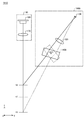
- FIG. 1 schematically shows a prism system 200 as an example of an optical element 100.
- the state of the prism system 200 when light from the H1 position enters the light receiving unit 130 is shown.
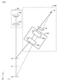
- the state of the prism system 200 when light from the H2 position enters the light receiving unit 130 is shown.
- the state of the prism system 200 when light from the H3 position enters the light receiving unit 130 is shown.
- 6 is a graph showing the dependence of the received light intensity I on the rotation angle ⁇ of the prism system 200.
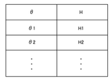
- the correspondence relationship between the rotation angle ⁇ of the prism system 200 and the height H of the object is shown in a table format.
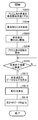
- FIG. 9 It is a flowchart which shows an example of the measuring method which measures the shape of a target object with light.
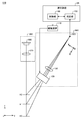
- An example of functional composition of optical sensor 910 in a 2nd embodiment is shown roughly.
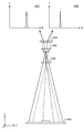
- the irradiated line light is schematically shown together with a signal of the received light intensity I obtained by the light receiving unit 130.
- An example of a functional composition of optical sensor 1110 in a 3rd embodiment is shown roughly.
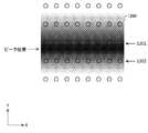
- the light receiving element arrangement in the light receiving unit 1130 and the intensity distribution of reflected light are schematically shown.
- 6 schematically shows the intensity distribution of reflected light when the rotation angle ⁇ of the prism system 200 is changed.
- 1 schematically shows a light projecting system 90 and a light receiving system 1460 of an optical sensor 1410 as a first modification of the first embodiment.
- a light projecting system 90 and a light receiving system 1560 of an optical sensor 1510 as a second modification of the first embodiment are schematically shown.
- 9 schematically shows a light projecting system 90 and a light receiving system 1660 of an optical sensor 1610 as a third modification of the first embodiment.
- An example of a functional composition of optical sensor 1710 in a 4th embodiment is shown roughly.
- An example of a functional composition of optical sensor 1810 in a 5th embodiment is shown roughly.
- 1 illustrates an example of a computer 2000 in which embodiments can be implemented in whole or in part.
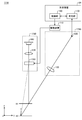
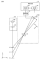
- FIG. 1 schematically shows an example of a functional configuration of the optical sensor 10 in the first embodiment.
- the optical sensor 10 includes a measuring device 20, a driving device 110, a light projecting system 90, and a light receiving system 60.
- the light projecting system 90 includes a light emitting unit 180 and a lens 170.
- the light receiving system 60 includes an optical element 100, a lens 120, and a light receiving unit 130.
- the measurement apparatus 20 includes a control unit 140 and a measurement unit 150.
- the measuring device 20 measures the shape of the object with light. Specifically, the measuring device 20 measures the shape of the object by measuring the height of the object. In the present embodiment, the measuring device 20 measures the height H of the surface of the object from a predetermined reference plane. In the present embodiment, “height” indicates the distance from the reference plane in the direction along the optical axis of the light projecting system 90. In the present embodiment, the height of the surface of the object from a predetermined reference plane may be referred to as “the height of the object”.
- the surface of the object is at a height H1 from the reference surface
- the surface of the object is at a height H2 from the reference surface
- the surface of the object is at a height H3 from the reference surface.
- the reflected light of an object whose surface is at a height H1 from the reference plane may be referred to as light from the H1 position.
- the reflected light of the object whose surface is at a height of H2 from the reference plane is referred to as light from the H2 position
- the reflected light of the object whose surface is at a height of H3 from the reference plane is referred to from the H3 position.
- the direction or the like may be expressed using an xyz coordinate system.
- the z-axis of the orthogonal coordinate system is determined in a direction parallel to the optical axis of the light projecting system 90.
- the direction in which the light from the light projecting system 90 travels is the z-axis minus direction.
- the y axis is determined so that the plane including the optical axis of the light projecting system 90 and the optical axis of the light receiving system 60 is parallel to the yz plane.
- the x-axis, y-axis, and z-axis are a right-handed orthogonal coordinate system.
- an XYZ coordinate system may be used to indicate the direction of the light receiving unit 130 or the like.
- the Z axis is determined in a direction parallel to the optical axis of the light receiving unit 130.
- the X axis is defined in the same direction as the x axis.
- the X axis, Y axis, and Z axis are a right-handed orthogonal coordinate system.
- the light emitting unit 180 emits light for measuring the shape of the object.
- the light emitting unit 180 is a laser diode (LD), for example, and emits laser light.
- the light emitted from the light emitting unit 180 enters the object.
- the light incident on the object is reflected by the surface of the object. At least a part of the light reflected by the surface of the object enters the light receiving system 60.
- LD laser diode
- the light incident on the light receiving system 60 passes through the optical element 100 and the lens 120 and enters the light receiving unit 130.
- the light receiving unit 130 is a member for detecting light from the object.
- the light receiving unit 130 includes a single light receiving element.
- the light receiving element may be a photoelectric conversion element such as a photodiode.
- the optical element 100 is provided in the optical path of light from the object.
- the optical element 100 changes the optical path of light from the object.
- the optical element 100 is an optical element whose amount of change in the optical path is variable.
- the control unit 140 changes the optical path with respect to the light receiving unit 130 by changing the state of the optical element 100.
- the driving device 110 changes the change amount of the optical path changed by the optical element 100 according to the control of the control unit 140.
- the light from the H1 position passes through the optical element 100 and enters the light receiving unit 130.
- the driving device 110 can change the change amount of the optical path by the optical element 100 so that the light from the H2 position enters the light receiving unit 130. Further, the driving device 110 can change the amount of change of the optical path by the optical element 100 so that light from the H3 position enters the light receiving unit 130.
- the control unit 140 changes the optical path of light from the object with respect to the light receiving unit 130. Specifically, the control unit 140 changes the amount of change of the optical path by the optical element 100 by controlling the driving device 110. And the measurement part 150 measures the shape of a target object based on the optical path when the light-receiving part 130 detects the light from a target object. For example, the measurement unit 150 acquires the drive amount of the drive device 110 from the control unit 140. The measuring unit 150 calculates the height H of the surface of the object from the reference plane based on the driving amount when the light receiving unit 130 detects light from the object. Thereby, the measurement part 150 measures the surface shape of a target object.
- the shape of the object can be measured by controlling the optical element 100 so that the light receiving unit 130 receives light from the object. Therefore, compared with the case where the shape of the object is measured from the light receiving level of the two-dimensional sensor, the measurement result of the object shape can be made less susceptible to the element arrangement of the two-dimensional sensor.
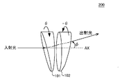
- FIG. 2 schematically shows a prism system 200 as an example of the optical element 100.
- the prism system 200 includes a first prism 101 and a second prism 102. Each of the first prism 101 and the second prism 102 is a wedge prism.
- the prism system 200 forms a Risley prism pair.
- the prism system 200 changes the optical path of light passing through the prism system 200. Specifically, as shown in FIG. 2, the prism system 200 deflects incident light to the prism system 200. More specifically, the incident light to the prism system 200 is deflected by the first prism 101 and the second prism 102, respectively. Thereby, the outgoing light from the prism system 200 travels in a different direction from the incident light.
- the first prism 101 and the second prism 102 are provided to be rotatable about the optical axis AX of the prism system 200.
- the driving device 110 rotates the first prism 101 and the second prism 102 in the opposite directions.
- the control unit 140 outputs an angle ⁇ indicating the rotation angle of the first prism 101 and the second prism 102 to the driving device 110 as a driving amount.
- the driving device 110 includes the first prism 101 and the second prism 102 such that the rotation angle of the first prism 101 is ⁇ from the reference angle and the rotation angle of the second prism 102 is ⁇ from the reference angle. Rotate. Thereby, the deflection angle ⁇ of the outgoing light with respect to the incident light changes according to the rotation angle ⁇ .
- the control unit 140 changes the optical path with respect to the light receiving unit 130 by changing the directions of the first prism 101 and the second prism 102.
- the directions of the first prism 101 and the second prism 102 correspond to the rotation angle around the optical axis AX of the prism system 200.
- the measurement unit 150 can measure the shape of the object based on the orientation of the prism when the light receiving unit 130 detects light from the object. It will be described later.
- the prism system 200 is an example of an optical element that changes the optical path by refraction.
- the driving device 110 may be a galvano motor.
- various actuators such as a servo motor and a stepping motor can be applied in addition to the galvano motor.
- the sign of the rotation angle ⁇ may be described as a plus direction in the clockwise direction when viewed in the traveling direction of incident light.
- the rotation angle of the first prism 101 with respect to the reference angle may be referred to as “the rotation angle of the prism system 200”.
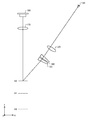
- FIG. 3 shows a state of the prism system 200 when light from the H1 position enters the light receiving unit 130. This state is referred to as a first state.
- the incident-side surface of the first prism 101 is parallel to the exit-side surface of the second prism 102. In this case, the light from the H1 position travels substantially straight in the yz plane.
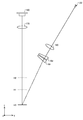
- FIG. 4 shows a state of the prism system 200 when light from the H2 position enters the light receiving unit 130. This state is referred to as a second state.
- the second state is a state in which the first prism 101 is rotated by ⁇ 90 ° and the second prism 102 is rotated by 90 ° with respect to the first state of FIG.
- FIG. 5 shows a state of the prism system 200 when light from the H3 position enters the light receiving unit 130. This state is referred to as a second state.
- the second state is a state in which the first prism 101 is rotated by 90 ° and the second prism 102 is rotated by ⁇ 90 ° with respect to the first state of FIG.
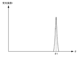
- FIG. 6 is a graph showing the dependence of the received light intensity I on the rotation angle ⁇ of the prism system 200.
- the controller 140 controls the driving device 110 to change the rotation angle ⁇ of the prism system 200 with time.
- the measuring unit 150 Based on the received light amount signal output from the light receiving unit 130, the measuring unit 150 detects a temporal change in the light reception intensity I of the light receiving unit 130. As described above, when the rotation angle ⁇ of the prism system 200 is changed, the peak of the light receiving intensity I of the light receiving unit 130 is obtained at an angle corresponding to the position of the surface of the object.
- the measurement unit 150 analyzes the light reception intensity I of the light reception unit 130 to identify the rotation angle ⁇ 1 of the prism system 200 when the peak of the light reception intensity I is obtained.
- the measurement unit 150 calculates the height H of the surface of the object based on the specified rotation angle ⁇ 1.
- FIG. 7 shows the correspondence between the rotation angle ⁇ of the prism system 200 and the height H of the object in a table format.
- the measuring unit 150 stores association information that associates the rotation angle ⁇ of the prism system 200 with the height H of the object.
- the rotation angle ⁇ is the rotation angle when the peak of the received light intensity I is obtained.
- FIG. 7 shows a table as an example of association information. The table associates the height H of the object with each of the plurality of rotation angles ⁇ .
- the measurement unit 150 refers to the table and determines H corresponding to the rotation angle ⁇ by the table, It is specified as the height of the object. For example, when the rotation angle of the prism system 200 when the peak of the received light intensity I is obtained is ⁇ 1, the measurement unit 150 specifies H1 associated with ⁇ 1 as the height of the object. When the rotation angle ⁇ referred to in the association information is a discrete value, the measurement unit 150 determines the height H of the object associated with the rotation angle ⁇ closest to the identified rotation angle as the object height. May be calculated as Further, the measurement unit 150 may calculate the height of the object by performing an interpolation operation or the like using a plurality of Hs associated with a plurality of rotation angles ⁇ .
- the height H of the object is determined based on the principle of triangulation, the position of the light emitting unit 180 and the light receiving unit 130, the angle of the optical axis of the irradiation light from the light emitting unit 180, and the optical system composed of the light receiving unit 130 and the lens 120. It is determined from the angle of the optical axis and the optical path change amount by the prism system 200.
- triangulation an angle from each of two reference points to a measurement target point is measured, and a base line connecting the two reference points is measured based on the measured angle and the positions of the two reference points. The position of the measurement target point is calculated.
- the prism system 200 does not change the optical path of incident light
- the light emitting unit 180 and the light receiving unit 130 correspond to two reference points in triangulation, and the optical axis of the irradiation light from the light emitting unit 180.
- the angle of the optical axis of the optical system composed of the light receiving unit 130 and the lens 120 correspond to the angle from each reference point to the measurement target point in triangulation.
- the position of the reference point of triangulation corresponding to the position of the light receiving unit 130 and the angle of the measurement target point from the reference point changes according to the optical path change amount of the prism system 200.
- the rotation angle ⁇ of the prism system 200, the position of the light receiving unit 130, and the angle of the optical axis of the optical system including the light receiving unit 130 and the lens 120 are determined. Therefore, the height H of the object is the position of the light emitting unit 180 and the light receiving unit 130, the angle of the optical axis of the light emitted from the light emitting unit 180, the angle of the optical axis of the optical system composed of the light receiving unit 130 and the lens 120, and
- the rotation angle ⁇ of the prism system 200 can be calculated.
- the measurement unit 150 applies the above-described method for calculating the height H of the object without using a table, and determines the positions of the light emitting unit 180 and the light receiving unit 130 and the optical axis of the irradiation light from the light emitting unit 180.
- the angle of the optical axis of the optical system composed of the light receiving unit 130 and the lens 120, and the rotation angle ⁇ of the prism system 200 when the peak of the received light intensity I is obtained the height H of the object is obtained. May be calculated.
- the measuring unit 150 receives the light
- the height H of the object may be calculated by calculation using the rotation angle ⁇ of the prism system 200 when the peak of intensity I is obtained.
- the positions of the light emitting unit 180 and the light receiving unit 130, the angle of the optical axis of the irradiation light from the light emitting unit 180, the optical system including the light receiving unit 130 and the lens 120 A function using the angle of the optical axis and the rotation angle ⁇ of the prism system 200 as arguments may be used.
- association information for specifying the height H of the object based on the rotation angle ⁇ of the prism system 200.
- the association information is not limited to a table or a function. Various data other than tables and functions can be adopted as the association information.
- FIG. 8 is a flowchart showing an example of a measurement method for measuring the shape of an object with light.
- control unit 140 controls the driving device 110 to rotate the prism system 200 until the rotation angle of the prism system 200 reaches a predetermined scanning start angle.
- control unit 140 controls the light emitting unit 180 to emit light from the light emitting unit 180.
- the measurement unit 150 starts reading the received light amount signal from the light receiving unit 130.
- the control unit 140 controls the driving device 110 to start the rotation of the prism system 200.
- the control unit 140 determines whether or not the rotation angle of the prism system 200 has reached a predetermined scanning end angle. If it is determined in S810 that the rotation angle of the prism system 200 has not reached the scanning end angle, the determination in S810 is repeated until the rotation angle of the prism system 200 reaches the scanning end angle.
- the measurement unit 150 receives the light received by the light receiving unit 130 based on the data of the received light intensity I obtained from the light receiving unit 130. A rotation angle ⁇ at which the intensity I reaches a peak is calculated.
- the measurement unit 150 calculates the height H of the object based on the rotation angle ⁇ at which the light reception intensity I of the light reception unit 130 reaches a peak.
- the measurement apparatus 20 outputs the data on the height H of the object calculated in S814 to the outside of the measurement unit 150, and ends the process.
- the prism system 200 is rotated until the scanning end angle is reached.
- the control unit 140 may stop the rotation of the prism system 200 when the peak of the received light intensity I is detected.
- the control unit 140 may change the optical path with respect to the light receiving unit 130 until the light receiving unit 130 detects light from the object.
- the function of the measuring apparatus 20 may be realized by a computer.
- the functions of the control unit 140 and the measurement unit 150 may be realized by a processor included in a computer.
- the program loaded in the computer may cause the processor to execute the procedure shown in the flowchart of FIG. 8 and the procedure for realizing the functions of the control unit 140 and the measurement unit 150.
- the control unit 140 outputs control signals for the driving device 110, the light receiving unit 130, and the light emitting unit 180, and the measuring unit 150 receives the light.
- a received light amount signal indicating the amount of light may be acquired from the light receiving unit 130.
- a specific hardware configuration of the measuring device 20 will be described later.
- the optical sensor 10 it is not necessary to provide a plurality of light receiving elements two-dimensionally unlike a two-dimensional sensor. Moreover, it is not necessary to calculate a peak from the outputs of a plurality of light receiving elements of the two-dimensional sensor. Therefore, the measurement result is not easily affected by the resolving power of the plurality of light receiving elements of the two-dimensional sensor. For example, it can suppress that the measurement accuracy of the height H of a target object falls by the width of the pitch width of the light receiving element of a two-dimensional sensor.
- the prism system 200 is used as the optical element 100. Thereby, even if the optical path is changed, the optical path length does not change greatly. Therefore, it is possible to prevent the light distortion and spread from being greatly different depending on the optical path. Therefore, the measurement accuracy of the height H of the object can be increased.
- the light receiving unit 130 includes a single light receiving element.
- a line sensor can be used instead of the light receiving unit 130.
- a mode in which a line sensor is used as the light receiving unit will be described as a second embodiment.
- FIG. 9 schematically shows an example of the functional configuration of the optical sensor 910 in the second embodiment.
- the optical sensor 910 includes a measuring device 20, a driving device 110, a light projecting system 990, and a light receiving system 960.
- the light projecting system 990 includes a light emitting unit 980 and a lens 970.
- the light receiving system 960 includes an optical element 100, a lens 120, and a light receiving unit 930.
- the measurement apparatus 20 includes a control unit 140 and a measurement unit 150.
- constituent elements included in the optical sensor 910 constituent elements having substantially the same functions as the constituent elements included in the optical sensor 10 in the first embodiment are denoted by the same reference numerals. Therefore, regarding the optical sensor 910, differences from the optical sensor 10 will be mainly described, and redundant description may be omitted.
- the light emitting unit 980 emits light having a spread at least in the x-axis direction.
- the lens 970 converts the light from the light emitting unit 980 into line light having a spread in the x-axis direction and irradiates the object.
- the light projecting system 990 irradiates the target with line light having a spread in the x-axis direction. That is, the light projecting system 990 emits line light that spreads in a direction substantially orthogonal to the yz plane.
- the light receiving unit 930 is a line sensor.
- the light receiving unit 930 is arranged so that the longitudinal direction is along the x-axis.
- the plurality of light receiving elements of the light receiving unit 930 are arranged in a direction along the x axis. That is, the light receiving unit 930 is provided so as to be substantially orthogonal to a plane including the optical axis of the irradiation light and the optical axis of the light receiving unit 930.
- the optical element 100 changes the optical path in the yz plane. Therefore, the light receiving unit 930 is provided so as to be substantially orthogonal to the direction of change of the optical path by the optical element 100.
- FIG. 10 schematically shows irradiated line light together with a signal of received light intensity I obtained by the light receiving unit 130.
- FIG. 10 is a view of the arrangement of the light receiving unit 930, the light emitting unit 980, and the lens 970 and the state of the line light viewed from the direction along the y-axis.
- the line light is represented by a solid line.
- the range of reflected light that can be received by the light receiving unit 930 is represented by a broken line in FIG.
- the alternate long and short dash line indicates the optical path of the reflected light from the surface of the portion where the height H of the object 1000 is low.
- a graph 1001 shows the received light intensity I of the reflected light from the surface of the portion where the height H of the object 1000 is low.
- the two-dot chain line indicates the optical path of the reflected light from the surface of the portion where the height H of the object 1000 is high.
- a graph 1002 is a graph of the received light intensity I of the reflected light from the surface of the portion where the height H of the object 1000 is high. Both the graph 1001 and the graph 1002 show the dependency of the prism system 200 on the rotation angle ⁇ .
- the rotation angle ⁇ at which the peak of the received light intensity I is obtained varies depending on the height H of the surface of the object 1000.
- the measuring unit 150 can calculate the height H of the position corresponding to each light receiving element from the rotation angle ⁇ at which the light receiving intensity I has a peak at each light receiving element included in the light receiving unit 930.
- the shape of the object 1000 can be measured by applying the light cutting method.
- a line sensor in comparison with an area sensor, can easily increase the number of light receiving elements per row. Therefore, by applying a line sensor as the light receiving unit 930, the measurable range of the surface shape of the object 1000 can be expanded as compared with the case of applying an area sensor.
- the line sensor can relatively easily increase the arrangement density of the light receiving elements arranged in a row. Therefore, by applying a line sensor as the light receiving unit 930, the spatial resolution in the x-axis direction of the object 1000 can be increased as compared with the case where an area sensor is applied. Further, as described in relation to the optical sensor 10 of the first embodiment, since the light path is changed by the optical element 100 and detected by the light receiving unit 930, the measurement result is influenced by the resolving power of the plurality of light receiving elements. Hateful. Therefore, for example, it can suppress that the measurement precision of the height H of the target object 1000 falls with the width of the pitch width of a some light receiving element.
- FIG. 11 schematically illustrates an example of a functional configuration of the optical sensor 1110 according to the third embodiment.
- the optical sensor 1110 includes a measuring device 1120, a driving device 110, a light projecting system 990, and a light receiving system 1160.
- the light projecting system 990 includes a light emitting unit 980 and a lens 970.
- the light receiving system 1160 includes the optical element 100, a lens 120, and a light receiving unit 1130.
- the measuring device 1120 includes a control unit 140, a measuring unit 150, and a switching unit 1142.
- optical sensor 1110 components having substantially the same functions as those provided in the optical sensor 910 in the second embodiment are denoted by the same reference numerals. Therefore, with respect to the optical sensor 1110, differences from the optical sensor 910 will be mainly described, and redundant description may be omitted.
- the light receiving unit 1130 is an area sensor.
- the light receiving unit 1130 is arranged so that the longitudinal direction is along the x-axis.
- the control unit 140 changes the optical path with respect to the light receiving unit 1130.
- the measurement unit 150 measures the shape of the object based on the optical path when light from the object is detected at a predetermined position on the light receiving unit 1130.
- the first measurement mode as described in relation to the second embodiment, the light reception of each of the plurality of light receiving elements provided in a specific row while changing the optical path by the optical element 100.
- the intensity I the light cutting method is applied to measure the height H of the object.
- the height H of the object may be measured by detecting.
- the control unit 140 causes the light receiving unit 1130 to receive light from the object in a state where the optical path is fixed to the light receiving unit 1130. Then, the control unit 140 measures the shape of the object on the light receiving unit 1130 based on the position where the light from the object is detected. Specifically, the measurement unit 150 calculates the height H of the object from the received light intensity distribution obtained from the plurality of light receiving elements arranged in the Y direction in the light receiving unit 1130.
- the switching unit 1142 switches between the first measurement mode and the second measurement mode.
- the switching unit 1142 may switch between the first measurement mode and the second measurement mode based on the selection of the user who uses the optical sensor 1110.
- the switching unit 1142 may switch between the first measurement mode and the second measurement mode based on the required measurement accuracy. As an example, switching to the first measurement mode may be performed when measurement accuracy is required, and switching to the second measurement mode may be performed when measurement accuracy is required.
- FIG. 12 schematically shows the arrangement of the light receiving elements in the light receiving unit 1130 and the intensity distribution of reflected light.
- ⁇ indicates the position of the light receiving element. Reflected light from a portion where the height H of the object is constant in the x-axis direction is incident on the light receiving unit 1130 with a band-shaped intensity distribution indicated by an intensity distribution 1200 in FIG. The shading of the intensity distribution 1200 indicates the magnitude of the light intensity.
- the dark and light portions represent the portions with high light intensity.
- the peak position of the intensity distribution in the Y-axis direction of the light receiving unit 1130 exists between the row 1201 and the row 1202.
- an error corresponding to the pitch width of the light receiving elements in the Y-axis direction can be included in the calculation result of the peak position. Therefore, an error corresponding to the pitch width of the light receiving elements in the Y-axis direction can be included in the measurement result of the shape of the object.
- FIG. 13 schematically shows the intensity distribution of the reflected light when the rotation angle ⁇ of the prism system 200 is changed.
- the portion corresponding to the intensity distribution 1200 in FIG. 12 shifts in the Y-axis direction.
- the measurement unit 150 calculates the height H of the object based on the rotation angle ⁇ when the peak position of the intensity distribution matches the row 1201 and the position of the row 1201. Thereby, since the peak position can be specified with high accuracy, the measurement error of the height H of the object can be reduced.
- control unit 140 changes the optical path of light from the object in the yz plane so that the peak position of the intensity distribution matches the row of the light receiving elements.
- the measurement unit 150 can reduce a measurement error of the height H of the target object using a plurality of measurement results obtained by the control unit 140 changing the optical path.
- the optical element 100 is configured to change the optical path in the xz plane instead of changing the optical path in the yz plane or in addition to changing the optical path in the yz plane. May be. “Changing the optical path in the xz plane” means changing the optical path when projected onto the xz plane. If the optical path is changed in the xz plane, the position of the object that can be detected by the light receiving element of the light receiving unit 1130 can be shifted in the x-axis direction. Therefore, the control unit 140 changes the optical path of light from the object using the optical element 100 so that the position of the object that can be detected by the light receiving element of the light receiving unit 1130 is shifted by a distance less than the pitch width of the light receiving element. To do. And the measurement part 150 can calculate the height H of a target object with high spatial resolution using the measurement result of multiple times obtained by the control part 140 changing an optical path.
- control unit 140 causes the light path of the light from the object to be the first light path, and causes the light from the object to enter the first region of the light receiving unit 1130. Further, the control unit 140 changes the optical path of light from the object from the first optical path to the second optical path, and causes the light from the object to enter the second region of the light receiving unit 1130. Then, the measurement unit 150 detects the light from the object by the plurality of light receiving elements provided in the first region of the light receiving unit 1130 and the plurality of light receiving elements provided in the second region of the light receiving unit 1130. The shape of the object is measured based on the detection result of light from the object.
- FIG. 14 schematically shows a light projecting system 90 and a light receiving system 1460 of an optical sensor 1410 as a first modification of the first embodiment.
- the optical sensor 1410 is different from the optical sensor 10 in that a flat plate 1400 is used instead of the prism system 200 as the optical element 100. Therefore, with respect to the optical sensor 1410, differences from the optical sensor 10 will be mainly described, and overlapping description may be omitted.
- the flat plate 1400 has an incident surface that is a surface on which light is incident and an output surface that is a surface from which light is emitted.
- the entrance surface is parallel to the exit surface.
- the entrance surface and the exit surface are provided in parallel to the x axis.
- the flat plate 1400 is provided to be rotatable around an axis AX1 parallel to the x axis.
- the control unit 140 controls the driving device 110 to rotate the flat plate 1400 around the axis AX1.
- the control unit 140 outputs information indicating the angle ⁇ of the flat plate 1400 with reference to a predetermined reference angle to the driving device 110.
- the optical path from the H2 position is indicated by a solid line
- the optical path from the H3 position is indicated by a broken line.
- control unit 140 changes the optical path with respect to the light receiving unit 130 by changing the direction of the flat plate 1400.
- the measurement part 150 measures the shape of a target object based on the direction of the flat plate 1400 when the light-receiving part 130 detects the light from a target object.
- the flat plate 1400 is an example of an optical element that changes the optical path by refraction.
- FIG. 15 schematically shows a light projecting system 90 and a light receiving system 1560 of an optical sensor 1510 as a second modification of the first embodiment.
- the optical sensor 1510 is different from the optical sensor 10 in that a flat mirror 1500 is used instead of the prism system 200 as the optical element 100. Therefore, with respect to the optical sensor 1510, differences from the optical sensor 10 will be mainly described, and redundant description may be omitted.
- the flat mirror 1500 is provided to be rotatable around an axis AX2 parallel to the x axis.
- the control unit 140 controls the driving device 110 to rotate the flat mirror 1500 around the axis AX2.
- the control unit 140 outputs information indicating the angle ⁇ of the flat mirror 1500 with reference to a predetermined reference angle to the driving device 110.
- the optical path from the H2 position is indicated by a solid line
- the optical path from the H3 position is indicated by a broken line.
- the control unit 140 changes the optical path of light from the object with respect to the light receiving unit 130 by changing the direction of the flat mirror 1500.
- the measurement unit 150 calculates the height H of the object based on the angle of the flat mirror 1500 when light is detected by the light receiving unit 130. In this way, the measurement unit 150 measures the shape of the object based on the orientation of the flat mirror 1500 when the light receiving unit 130 detects light from the object.
- a flat mirror 1500 having one reflecting surface is illustrated.
- the flat mirror 1500 is an example of an optical element that changes an optical path by reflection.
- a polygon mirror, a galvanometer mirror, or the like can be applied instead of the flat mirror 1500.
- FIG. 16 schematically shows a light projecting system 90 and a light receiving system 1660 of an optical sensor 1610 as a third modification of the first embodiment.
- the optical sensor 1610 is different from the optical sensor 10 in that an acoustooptic deflector 1600 is used instead of the prism system 200 as the optical element 100. Therefore, with respect to the optical sensor 1610, differences from the optical sensor 10 will be mainly described, and redundant description may be omitted.
- the acousto-optic deflector 1600 includes a first acousto-optic deflector 1601 and a second acousto-optic deflector 1602.
- Each of the first acousto-optic deflector 1601 and the second acousto-optic deflector 1602 has an elastic medium to which ultrasonic waves are applied by a vibrator such as a piezoelectric element.
- Incident light can be diffracted by a coarse-wave diffraction grating generated in an elastic medium by ultrasonic waves.
- the first acoustooptic deflector 1601 and the second acoustooptic deflector 1602 diffract incident light by the Bragg effect.
- the incident angle at which diffraction occurs varies with the frequency of the ultrasonic wave. Therefore, the control unit 140 outputs information indicating the frequency f of the electric signal applied to the vibrator provided in the first acoustooptic deflector 1601 and the second acoustooptic deflector 1602 to the driving device 110.
- the driving device 110 drives the respective vibrators of the first acousto-optic deflector 1601 and the second acousto-optic deflector 1602 with the frequency f specified by the control unit 140, thereby allowing light incident at a specific incident angle. To deflect.
- the optical path from the H2 position is indicated by a solid line
- the optical path from the H3 position is indicated by a broken line.
- the optical path of the light from the object is moved using two acoustooptic deflectors and received by the light receiving unit 130.
- the number of acoustooptic deflectors is not limited to two.
- the light from the object may be received by the light receiving unit 130 by changing the angle of the optical path using one acousto-optic deflector.
- the optical path can be changed using one or more acousto-optic deflectors.
- the light from the object may be received by any one of the light receiving elements on the line sensor or the area sensor.
- an electro-optic deflection light device may replace with the acousto-optic deflector 1600 in the optical sensor 1610, and an electro-optic deflection light device may be applied.
- the electro-optic deflector include an optical element having an electro-optic effect whose refractive index changes according to an electric field, such as a KTN crystal or a liquid crystal.
- the control unit 140 controls the optical path of light from the object by controlling the voltage applied to the electro-optic deflector.
- the measurement unit 150 calculates the height H of the object based on the voltage applied to the electro-optic deflector when light is detected by the light receiving unit 130.
- An electro-optic deflector is an example of an optical element that changes an optical path by refraction.
- FIG. 17 schematically illustrates an example of a functional configuration of the optical sensor 1710 according to the fourth embodiment.
- the optical sensor 1710 includes a measuring device 20, a driving device 110, a light projecting system 1790, and a light receiving system 1760.
- the light projecting system 1790 includes a light emitting unit 980, a lens 970, and an optical element 1700.
- the light receiving system 1760 includes a lens 120 and a light receiving unit 930.
- the measurement apparatus 20 includes a control unit 140 and a measurement unit 150.
- optical sensor 1710 components having substantially the same functions as those provided in the optical sensor 910 in the second embodiment are denoted by the same reference numerals. Therefore, regarding the optical sensor 1710, differences from the optical sensor 910 will be mainly described, and redundant description may be omitted.
- the optical element 1700 is provided in an optical path of incident light that is light incident on an object.
- the optical element 1700 changes the optical path of the incident light to the object in at least one of the y-axis direction and the x-axis direction.
- the optical element 1700 deflects incident light on the object.
- the light from the position on the optical axis of the light receiving unit 930 is incident on the light receiving unit 930.
- the measurement unit 150 calculates the height H3 of the object at the position P in the y-axis direction based on the angle at which the optical element 1700 deflects the incident light.
- the measuring unit 150 includes the position of the light receiving element in which light is detected and the incident by the optical element 1700 among the plurality of light receiving elements included in the light receiving unit 930.
- the position where the height is H1 is calculated from the light deflection angle.
- the measurement part 150 can measure the shape of a target object by changing the optical path of the incident light to a target object.
- the optical element 1700 deflects incident light in the x-axis direction
- the position of the object that can be detected by the light receiving element of the light receiving unit 930 can be shifted. Therefore, according to the optical sensor 1710, the position having the height H1 in the object can be detected with high spatial resolution.
- the control unit 140 changes the optical path of the light incident on the object with respect to the light receiving unit 930.
- the measurement part 150 measures the shape of a target object based on the optical path when the light-receiving part 930 detects the light from a target object.
- a mode in which each light projecting system includes an optical element 1700 can be employed. That is, the control unit 140 may change the optical paths of both the light incident on the object and the light from the object with respect to the light receiving unit 930.
- FIG. 18 schematically illustrates an example of a functional configuration of the optical sensor 1810 according to the fifth embodiment.
- the optical sensor 1810 includes a measuring device 20, a driving device 110, a light projecting system 990, and a light receiving system 1860.
- the light projecting system 990 includes a light emitting unit 980 and a lens 970.
- the light receiving system 1860 includes a lens 120 and a light receiving unit 930.
- the measurement apparatus 20 includes a control unit 140 and a measurement unit 150.
- optical sensor 1810 components having substantially the same functions as those provided in the optical sensor 910 in the second embodiment are denoted by the same reference numerals. Therefore, with respect to the optical sensor 1810, differences from the optical sensor 910 will be mainly described, and redundant description may be omitted.
- the light receiving unit 930 is provided to be movable in a direction orthogonal to the optical axis of the light receiving unit 930.
- the driving device 110 moves the light receiving unit 930 in a direction orthogonal to the Y axis.
- the driving device 110 acquires information indicating the amount of movement of the light receiving unit 930 from the reference position from the control unit 140.
- the driving device 110 moves the light receiving unit 930 in the Y-axis direction of the light receiving unit 930 according to the information acquired from the control unit 140. In this way, the control unit 140 changes the position of the light receiving unit 930 with respect to the optical path of light from the object.
- the light receiving unit 930 can scan the light from the object in the Y-axis direction.
- the measuring unit 150 calculates the height H from the object based on the position of the light receiving unit 930 in the Y-axis direction when the light reception intensity peak of the light receiving unit 930 is obtained.
- the number of light receiving elements per row can be easily increased as compared with the area sensor. Therefore, by applying a line sensor as the light receiving unit 930, it is possible to widen the measurable range of the surface shape of the object in the x-axis direction compared to the case of applying an area sensor.
- the spatial resolution in the x-axis direction of the surface shape of the object can be increased as compared with the case where an area sensor is applied.
- the light receiving unit 930 can be scanned in the Y-axis direction, so that the measurable range and spatial resolution in the Y-axis direction can be increased.
- control unit 140 may change the position of the light receiving unit 930 until light from the object is detected by the light receiving unit 930.
- the control unit 140 may stop the change in the position of the light receiving unit 930 when the light receiving unit 930 detects light from the object.
- the light receiving system detects a part of the diffuse reflected light generated by the object.
- a method for detecting total reflection light generated by an object may be applied.
- the measurement target of the optical sensor in each embodiment described above is an electrode formed on a substrate.
- the measurement target of the optical sensor may be a bump or the like formed on the substrate.
- the measurement target of the optical sensor may be the inner wall of the tunnel.
- the measurement target of the optical sensor is not limited to these.
- the measurement accuracy and measurement range can be made less affected by the element arrangement of the two-dimensional sensor, compared to the case where only the two-dimensional sensor is used.
- Each block in the block diagram may represent (1) a stage of the process in which the operation is performed or (2) a section of the device responsible for performing the operation.
- each of the control unit 140 and the measurement unit 150 may represent one section of the measurement device 20.
- Certain stages and sections are implemented by dedicated circuitry, programmable circuitry supplied with computer readable instructions stored on a computer readable medium, and / or processor supplied with computer readable instructions stored on a computer readable medium. It's okay.
- Dedicated circuitry may include digital and / or analog hardware circuitry and may include integrated circuits (ICs) and / or discrete circuits.
- Programmable circuits include memory elements such as logical AND, logical OR, logical XOR, logical NAND, logical NOR, and other logical operations, flip-flops, registers, field programmable gate arrays (FPGA), programmable logic arrays (PLA), etc. Reconfigurable hardware circuitry, including and the like.
- Computer readable media may include any tangible device capable of storing instructions to be executed by a suitable device, such that a computer readable medium having instructions stored thereon is specified in a flowchart or block diagram. Constitutes at least part of the product including instructions that may be executed to provide a means for performing the operations. Examples of computer readable media may include electronic storage media, magnetic storage media, optical storage media, electromagnetic storage media, semiconductor storage media, and the like.
- Computer readable media include floppy disks, diskettes, hard disks, random access memory (RAM), read only memory (ROM), erasable programmable read only memory (EPROM or flash memory), Electrically erasable programmable read only memory (EEPROM), static random access memory (SRAM), compact disc read only memory (CD-ROM), digital versatile disc (DVD), Blu-ray (RTM) disc, memory stick, integrated A circuit card or the like may be included.
- RAM random access memory
- ROM read only memory
- EPROM or flash memory erasable programmable read only memory
- EEPROM Electrically erasable programmable read only memory
- SRAM static random access memory
- CD-ROM compact disc read only memory
- DVD digital versatile disc
- RTM Blu-ray
- Computer readable instructions can be assembler instructions, instruction set architecture (ISA) instructions, machine instructions, machine dependent instructions, microcode, firmware instructions, state setting data, or object oriented programming such as Smalltalk, JAVA, C ++, etc. Including any source code or object code written in any combination of one or more programming languages, including languages and conventional procedural programming languages such as "C" programming language or similar programming languages Good.
- Computer readable instructions may be directed to a general purpose computer, special purpose computer, or other programmable data processing device processor or programmable circuit locally or in a wide area network (WAN) such as a local area network (LAN), the Internet, etc.
- the computer-readable instructions may be executed to provide a means for performing the operations provided through and specified in the flowchart or block diagram.
- processors include computer processors, processing units, microprocessors, digital signal processors, controllers, microcontrollers, and the like.
- FIG. 19 illustrates an example of a computer 2000 in which a plurality of embodiments may be embodied in whole or in part.
- a program installed in the computer 2000 causes the computer 2000 to perform an operation associated with the device or one or more sections of the device, causing the computer 2000 to function as the device according to the embodiment or one or more sections of the device. And / or a process according to an embodiment or a stage of the process can be executed.
- Such a program may be executed by CPU 2012 to cause computer 2000 to perform certain operations associated with some or all of the blocks in the flowcharts and block diagrams described herein.
- the computer 2000 includes a CPU 2012, a RAM 2014, a graphic controller 2016, and a display device 2018, which are connected to each other by a host controller 2010.
- Computer 2000 also includes ROM 2030.
- the ROM 2030 is connected to the host controller 2010 via the input / output controller 2020.
- the computer 2000 also includes input / output units such as a communication interface 2022, a hard disk drive 2024, a DVD-ROM drive 2026, and a memory card drive 2028, which are connected to the host controller 2010 via the input / output controller 2020.
- the computer 2000 also includes legacy input / output units such as a keyboard 2042, which are connected to an input / output controller 2020 via an input / output chip 2040.
- the CPU 2012 operates according to a program stored in the ROM 2030 and / or the RAM 2014, thereby controlling each unit.
- the graphic controller 2016 acquires a frame buffer or the like provided in the RAM 2014 or image data generated by the CPU 2012 in the RAM 2014 and causes the display device 2018 to display the image data.
- the communication interface 2022 communicates with other electronic devices via a network.
- the hard disk drive 2024 stores programs and data used by the CPU 2012 in the computer 2000.
- the DVD-ROM drive 2026 reads a program and / or data from the DVD-ROM 2001 and provides the program and / or data to the hard disk drive 2024 via the RAM 2014.
- the memory card drive 2028 reads programs and / or data from the memory card 2003, and provides the programs and / or data to the hard disk drive 2024 via the RAM 2014.
- the memory card drive 2028 may write a program and / or data to the memory card 2003.
- the ROM 2030 stores therein a boot program executed by the computer 2000 at the time of activation and / or a program depending on the hardware of the computer 2000.
- the input / output chip 2040 may also connect various input / output units to the input / output controller 2020 via a parallel port, serial port, keyboard port, mouse port, and the like.
- the program is provided by a computer-readable medium such as a DVD-ROM 2001 or a memory card 2003.
- the program is read from a computer-readable medium, installed in the hard disk drive 2024, the RAM 2014, and / or the ROM 2030, which are also examples of the computer-readable medium, and executed by the CPU 2012.
- Information processing described in these programs is read by the computer 2000 to bring about cooperation between the programs and the various types of hardware resources.
- the apparatus or method may be configured by implementing information operations or processing in accordance with the use of computer 2000.
- the CPU 2012 executes a communication program loaded in the RAM 2014 and performs communication processing on the communication interface 2022 based on the processing described in the communication program. You may order.
- the communication interface 2022 reads and reads transmission data stored in a transmission buffer processing area provided in a recording medium such as the RAM 2014, the hard disk drive 2024, the DVD-ROM 2001, or the memory card 2003 under the control of the CPU 2012.
- the transmission data is transmitted to the network, or the reception data received from the network is written in a reception buffer processing area provided on the recording medium.
- the CPU 2012 reads all or a necessary part of a file or database stored in an external recording medium such as the hard disk drive 2024, the DVD-ROM 2001, the memory card 2003 or the like into the RAM 2014, Various types of processing may be performed. Next, the CPU 2012 writes back the processed data to the external recording medium.
- an external recording medium such as the hard disk drive 2024, the DVD-ROM 2001, the memory card 2003 or the like.
- the CPU 2012 performs various types of operations, information processing, condition determination, conditional branching, unconditional branching, information retrieval / information described in this specification and specified by the instruction sequence of the program for the data read from the RAM 2014. Various types of processing, including replacement, may be performed, and the result written back to the RAM 2014. Further, the CPU 2012 may search for information in files, databases, etc. in the recording medium. For example, when a plurality of entries each having an attribute value of the first attribute associated with the attribute value of the second attribute are stored in the recording medium, the CPU 2012 specifies the attribute value of the first attribute. The entry matching the condition is searched from the plurality of entries, the attribute value of the second attribute stored in the entry is read, and the first attribute satisfying a predetermined condition is thereby read. The attribute value of the associated second attribute may be obtained.
- the above-described program or software module may be stored on a computer-readable medium on or near the computer 2000.
- a recording medium such as a hard disk or RAM provided in a server system connected to a dedicated communication network or the Internet can be used as a computer-readable medium, thereby providing the program to the computer 2000 via the network. You can do it.
- Control system 10 10 optical sensor 20 two-dimensional image sensor 60 Light receiving system 90 Floodlight system 100 optical elements 101 First prism 102 2nd prism 110 Drive device 120 lenses 130 Light receiver 140 Control unit 150 Measuring unit 170 lenses 180 Light emitter 200 Prism system 910 Optical sensor 930 Light receiver 960 Light receiving system 970 lens 980 light emitting part 990 Floodlight system 1001 graph 1002 Graph 1110 Optical sensor 1120 Measuring device 1130 Light receiver 1142 switching unit 1160 Light receiving system 1200 intensity distribution Line 1201 Line 1202 1400 flat plate 1410 Optical sensor 1460 Light receiving system 1500 Flat mirror 1510 Optical sensor 1560 light receiving system 1600 Acousto-optic deflector 1601 First acousto-optic deflector 1602 Second acousto-optic deflector 1610 Optical sensor 1660 Light receiving system 1700 Optical device 1710 Optical sensor 1760 Light receiving system 1790 Floodlight system 1810 Optical sensor 1860 Light receiving system 2000 computers 2001 DVD-ROM 2003 Memory card 2010
Landscapes
- Physics & Mathematics (AREA)
- General Physics & Mathematics (AREA)
- Electromagnetism (AREA)
- Engineering & Computer Science (AREA)
- Radar, Positioning & Navigation (AREA)
- Remote Sensing (AREA)
- Length Measuring Devices By Optical Means (AREA)
- Measurement Of Optical Distance (AREA)
Abstract
測定装置は、対象物の形状を光により測定する。測定装置は、対象物からの光を検出するための受光部に対する、対象物に入射する光及び前記対象物からの光の少なくとも一方の光路を変化させる制御部と、受光部が前記対象物からの光を検出した場合の前記光路に基づいて、対象物の形状を測定する測定部とを備える。対象物の形状を光により測定する測定方法は、対象物からの光を検出するための受光部に対する、対象物に入射する光及び対象物からの光の少なくとも一方の光路を変化させる段階と、受光部が対象物からの光を検出した場合の光路に基づいて、対象物の形状を測定する段階とを備える。
Description
本発明は、測定装置、光学式センサ、測定方法及びプログラムに関する。
測定対象物に照射した投光ビームの反射光を2次元イメージセンサによって受光して、受光レベルのピーク位置から物体の表面までの変位又は距離を算出する光式変位センサが知られている(例えば、特許文献1参照)。
特許文献1 特開2004-170437号公報
特許文献1 特開2004-170437号公報
対象物からの光を2次元センサで受光する方式は、測定精度又は測定範囲が2次元センサの素子配置の影響を受け易いという課題があった。
本発明の第1の態様においては、測定装置が提供される。測定装置は、対象物の形状を光により測定してよい。測定装置は、対象物からの光を検出するための受光部に対する、対象物に入射する光及び対象物からの光の少なくとも一方の光路を変化させる制御部を備えてよい。測定装置は、受光部が対象物からの光を検出した場合の光路に基づいて、対象物の形状を測定する測定部を備えてよい。
測定装置は、光路を変更する光素子を備えてよい。制御部は、光素子の状態を変化させることにより、受光部に対して光路を変化させてよい。
光素子は、屈折又は回折により光路を変更してよい。制御部は、光素子の向きを変化させることにより、受光部に対して光路を変化させてよい。測定部は、受光部が対象物からの光を検出した場合の光素子の向きに基づいて、対象物の形状を測定してよい。
光素子は、1つ以上のプリズムを有してよい。制御部は、プリズムの向きを変化させることにより、受光部に対して光路を変化させてよい。測定部は、受光部が対象物からの光を検出した場合のプリズムの向きに基づいて、対象物の形状を測定してよい。
光素子は、反射により光路を変更してよい。制御部は、光素子の向きを変化させることにより、受光部に対して光路を変化させてよい。測定部は、受光部が対象物からの光を検出した場合の光素子の向きに基づいて、対象物の形状を測定してよい。
制御部は、受光部によって対象物からの光が検出されるまで、受光部に対して光路を変化させてよい。
制御部は、受光部によって対象物からの光が検出されるまで、受光部の位置を変化させてよい。
受光部は、光路の変化方向に略直交するように設けられたラインセンサであってよい。
受光部は、エリアセンサであってよい。制御部は、対象物からの光の光路を第1の光路にして、対象物からの光をエリアセンサの第1の領域に入射させてよい。制御部は、対象物からの光の光路を第1の光路から第2の光路に変化させて、対象物からの光をエリアセンサの第2の領域に入射させてよい。測定部は、エリアセンサの第1の領域に設けられた複数の受光素子による対象物からの光の検出結果と、エリアセンサの第2の領域に設けられた複数の受光素子による対象物からの光の検出結果とに基づいて、対象物の形状を測定してよい。
受光部は、エリアセンサであってよい。測定装置は、第1の測定モードにおいて、制御部は、エリアセンサに対して光路を変化させてよい。測定部は、エリアセンサ上の予め定められた位置で対象物からの光が検出された場合の光路に基づいて、対象物の形状を測定してよい。第2の測定モードにおいて、制御部は、エリアセンサに対して光路が固定された状態でエリアセンサに対象物からの光を受光させてよい。測定部は、エリアセンサ上における、対象物からの光が検出された位置に基づいて、対象物の形状を測定してよい。測定装置は、第1の測定モードと第2の測定モードとを切り換える切替部を備えてよい。
本発明の第2の態様においては、光学式センサが提供される。光学式センサは、上記の測定装置と、受光部とを備えてよい。
光学式センサは、対象物に入射する光を出射する発光部を備えてよい。
本発明の第3の態様においては、測定方法が提供される。測定方法は、対象物の形状を光により測定してよい。測定方法は、対象物からの光を検出するための受光部に対する、対象物に入射する光及び対象物からの光の少なくとも一方の光路を変化させる段階を備えてよい。測定方法は、受光部が対象物からの光を検出した場合の光路に基づいて、対象物の形状を測定する段階を備えてよい。
本発明の第4の態様においては、プログラムが提供される。プログラムは、対象物の形状を測定するためのプログラムであってよい。プログラムは、コンピュータに、対象物からの光を検出するための受光部に対する、対象物に入射する光及び対象物からの光の少なくとも一方の光路を変化させる手順を実行させてよい。プログラムは、受光部が対象物からの光を検出した場合の光路に基づいて、対象物の形状を測定する手順を実行させてよい。
上記の発明の概要は、本発明の特徴の全てを列挙したものではない。これらの特徴群のサブコンビネーションも発明となりうる。
以下、発明の実施の形態を通じて本発明を説明するが、以下の実施形態は請求の範囲にかかる発明を限定するものではない。また、実施形態の中で説明されている特徴の組み合わせの全てが発明の解決手段に必須であるとは限らない。
図1は、第1実施形態における光学式センサ10の機能構成の一例を概略的に示す。光学式センサ10は、測定装置20と、駆動装置110と、投光系90と、受光系60とを備える。投光系90は、発光部180と、レンズ170とを備える。受光系60は、光素子100と、レンズ120と、受光部130とを備える。測定装置20は、制御部140と、測定部150とを有する。
測定装置20は、対象物の形状を光により測定する。具体的には、測定装置20は、対象物の高さを測定することにより、対象物の形状を測定する。本実施形態において、測定装置20は、対象物の表面の、予め定められた基準面からの高さHを測定する。本実施形態において、「高さ」は、投光系90の光軸に沿う方向における、基準面からの距離を示す。本実施形態において、対象物の表面の、予め定められた基準面からの高さのことを「対象物の高さ」と呼ぶ場合がある。
本実施形態において、対象物の表面が基準面から高さH1にある場合と、対象物の表面が基準面から高さH2にある場合と、対象物の表面が基準面から高さH3にある場合とを特に取り上げて説明する場合がある。本実施形態の説明において、表面が基準面からH1の高さにある対象物の反射光を、H1位置からの光と呼ぶ場合がある。同様に、表面が基準面からH2の高さにある対象物の反射光を、H2位置からの光と呼び、表面が基準面からH3の高さにある対象物の反射光を、H3位置からの光と呼ぶ場合がある。
また、実施形態の説明において、xyz座標系を用いて方向等を表す場合がある。直交座標系のz軸を、投光系90の光軸に平行な向きに定める。投光系90からの光が進む方向を、z軸マイナス方向とする。また、投光系90の光軸及び受光系60の光軸を含む面がyz面に平行になるように、y軸を定める。x軸、y軸、z軸は右手系の直交座標系とする。また、実施形態の説明において、受光部130の方向等を表す場合に、XYZ座標系を用いる場合がある。Z軸は、受光部130の光軸に平行な方向に定める。X軸は、x軸と同じ方向に定める。X軸、Y軸、Z軸は右手系の直交座標系とする。
投光系90において、発光部180は、対象物の形状を測定するための光を出射する。発光部180は、例えばレーザダイオード(LD)であり、レーザ光を出射する。発光部180が出射した光は、対象物に入射する。対象物に入射した光は、対象物の表面で反射する。受光系60には、対象物の表面で反射した光のうちの少なくとも一部の光が入射する。
受光系60に入射した光は、光素子100及びレンズ120を通過して、受光部130に入射する。受光部130は、対象物からの光を検出するための部材である。本実施形態において、受光部130は、単一の受光素子を備えるとする。受光素子は、例えばフォトダイオード等の光電変換素子であってよい。
光素子100は、対象物からの光の光路中に設けられる。光素子100は、対象物からの光の光路を変化させる。光素子100は、光路の変更量が可変な光素子である。制御部140は、光素子100の状態を変化させることにより、受光部130に対して光路を変化させる。
駆動装置110は、制御部140の制御に従って、光素子100が変更する光路の変更量を変化させる。対象物の表面が基準面からH1の高さにある場合、H1位置からの光は、光素子100を通過して受光部130に入射する。駆動装置110は、H2位置からの光が、受光部130に入射するように、光素子100による光路の変更量を変化させることができる。また、駆動装置110は、H3位置からの光が、受光部130に入射するように、光素子100による光路の変更量を変化させることができる。
このように、制御部140は、受光部130に対する、対象物からの光の光路を変化させる。具体的には、制御部140は、駆動装置110を制御することにより、光素子100による光路の変更量を変化させる。そして、測定部150は、受光部130が対象物からの光を検出した場合の光路に基づいて、対象物の形状を測定する。例えば、測定部150は、駆動装置110の駆動量を、制御部140から取得する。測定部150は、受光部130が対象物からの光を検出した場合における駆動量に基づいて、基準面からの対象物の表面の高さHを算出する。これにより、測定部150は、対象物の表面形状を測定する。
光学式センサ10によれば、受光部130が対象物からの光を受光するように光素子100を制御することによって、対象物の形状を測定することができる。そのため、対象物の形状を2次元センサの受光レベルから測定する場合に比べて、対象物の形状の測定結果が2次元センサの素子配列の影響を受けにくくすることができる。
図2は、光素子100の一例としてのプリズム系200を概略的に示す。プリズム系200は、第1プリズム101と第2プリズム102とを備える。第1プリズム101及び第2プリズム102は、それぞれウェッジプリズムである。プリズム系200は、リズレープリズム対を形成する。
プリズム系200は、プリズム系200を通過する光の光路を変更する。具体的には、図2に示されるように、プリズム系200は、プリズム系200への入射光を偏向する。より具体的には、プリズム系200への入射光は、第1プリズム101及び第2プリズム102によってそれぞれ偏向される。これにより、プリズム系200からの出射光は、入射光とは異なる向きに進む。
第1プリズム101及び第2プリズム102は、プリズム系200の光軸AXを中心に回転可能に設けられる。駆動装置110は、第1プリズム101及び第2プリズム102を互いに逆回りに回転させる。制御部140は、第1プリズム101及び第2プリズム102の回転角度を示す角度θを、駆動量として駆動装置110に出力する。この場合、駆動装置110は、第1プリズム101の回転角度が基準角度からθになり、第2プリズム102の回転角度が基準角度から-θになるように、第1プリズム101及び第2プリズム102を回転させる。これにより、入射光に対する出射光の偏向角φが、回転角度θに応じて変化する。
このように、制御部140は、第1プリズム101及び第2プリズム102の向きを変化させることにより、受光部130に対して光路を変化させる。プリズム系200において、第1プリズム101及び第2プリズム102の向きとは、プリズム系200の光軸AXのまわりの回転角度に対応する。測定部150は、受光部130が対象物からの光を検出した場合のプリズムの向きに基づいて、対象物の形状を測定することができる。後述する。なお、プリズム系200は、屈折により光路を変更する光素子の一例である。
なお、駆動装置110はガルバノモータであってよい。駆動装置110として、ガルバノモータの他に、サーボモータ、ステッピングモータ等、様々なアクチュエータを適用できる。
なお、本実施形態では、回転角度θの符号について、入射光の進行方向に見た場合の右回り方向をプラス方向として説明する場合がある。また、基準角度に対する第1プリズム101の回転角度を、「プリズム系200の回転角度」と呼ぶ場合がある。
図3は、H1位置からの光が受光部130に入射する場合のプリズム系200の状態を示す。この状態を第1の状態と呼ぶ。第1の状態において、第1プリズム101の入射側の面は、第2プリズム102の出射側の面と平行となっている。この場合、H1位置からの光は、yz面内において実質的に直進する。
図4は、H2位置からの光が受光部130に入射する場合のプリズム系200の状態を示す。この状態を第2の状態と呼ぶ。第2の状態は、図3の第1の状態に対して、第1プリズム101を-90°回転させ、第2プリズム102を90°回転させた状態である。
図5は、H3位置からの光が受光部130に入射する場合のプリズム系200の状態を示す。この状態を第2の状態と呼ぶ。第2の状態は、図3の第1の状態に対して、第1プリズム101を90°回転させ、第2プリズム102を-90°回転させた状態である。
図6は、プリズム系200の回転角度θに対する受光強度Iの依存性を示すグラフである。制御部140は、駆動装置110を制御することにより、プリズム系200の回転角度θを時間的に変化させる。測定部150は、受光部130が出力する受光量信号に基づいて、受光部130の受光強度Iの時間変化を検出する。上述したように、プリズム系200の回転角度θを変化させていくと、対象物の表面の位置に対応する角度において、受光部130の受光強度Iのピークが得られる。
測定部150は、受光部130の受光強度Iを解析することにより、受光強度Iのピークが得られたときのプリズム系200の回転角度θ1を特定する。測定部150は、特定した回転角度θ1に基づいて、対象物の表面の高さHを算出する。
図7は、プリズム系200の回転角度θと対象物の高さHとの対応関係をテーブル形式で示す。測定部150は、プリズム系200の回転角度θを対象物の高さHを対応付ける対応付け情報を記憶する。ここで回転角度θは、受光強度Iのピークが得られたときの回転角度である。図7では、対応付け情報の一例としてのテーブルを示す。テーブルは、複数の回転角度θのそれぞれに対して、対象物の高さHを対応付ける。
測定部150は、受光強度Iのピークが得られたときのプリズム系200の回転角度θが得られた場合、当該テーブルを参照して、テーブルによって回転角度θに対応づけられているHを、物体の高さとして特定する。例えば、測定部150は、受光強度Iのピークが得られたときのプリズム系200の回転角度がθ1である場合、θ1に対応づけられているH1を、物体の高さとして特定する。なお、対応付け情報において参照する回転角度θが離散値である場合、測定部150は、特定した回転角度に最も近い回転角度θに対応付けられている物体の高さHを、物体の高さとして算出してよい。また、測定部150は、複数の回転角度θに対応づけられた複数のHを用いて補間演算等をすることによって、物体の高さを算出してもよい。
対象物の高さHは、三角測量の原理に基づいて、発光部180及び受光部130の位置、発光部180からの照射光の光軸の角度、受光部130及びレンズ120からなる光学系の光軸の角度、並びに、プリズム系200による光路変更量から定まる。一般に、三角測量においては、2つの基準点のそれぞれから測定対象点への角度を測定して、測定された角度と、2つの基準点の位置とに基づいて、2つの基準点を結ぶ基線に対する測定対象点の位置を算出する。光学式センサ10において、プリズム系200が入射光の光路を変更しないとすると、発光部180及び受光部130が、三角測量における2つの基準点に対応し、発光部180からの照射光の光軸の角度、及び、受光部130及びレンズ120からなる光学系の光軸の角度が、三角測量における各基準点から測定対象点への角度に対応する。これにより、三角測量の原理に基づいて、発光部180と発光部180とを結ぶ基線に対する対象物の位置を測定することができ、それにより、特定の基準面からの対象物の高さHを測定できる。光学式センサ10においてはプリズム系200が光路を変更する。そのため、受光部130の位置に対応する三角測量の基準点の位置、及び、当該基準点から測定対象点の角度の少なくとも一方が、プリズム系200の光路変更量に応じて変化するが、それらは、プリズム系200の回転角度θと、受光部130の位置と、受光部130及びレンズ120からなる光学系の光軸の角度とによって定まる。よって、対象物の高さHは、発光部180及び受光部130の位置、発光部180からの照射光の光軸の角度、受光部130及びレンズ120からなる光学系の光軸の角度、並びに、プリズム系200の回転角度θから算出することができる。よって、発光部180及び受光部130の位置、発光部180からの照射光の光軸の角度、受光部130及びレンズ120からなる光学系の光軸の角度が固定の場合、複数の回転角度θのそれぞれについて対象物の高さHを予め算出しておき、図7に示すように回転角度θと対象物の高さHとの対応関係をテーブルとして格納することができる。
なお、測定部150は、テーブルを用いることなく、上述した対象物の高さHの算出方法を適用して、発光部180及び受光部130の位置、発光部180からの照射光の光軸の角度、受光部130及びレンズ120からなる光学系の光軸の角度、並びに、受光強度Iのピークが得られたときのプリズム系200の回転角度θを用いた演算により、対象物の高さHを算出してよい。発光部180及び受光部130の位置、発光部180からの照射光の光軸の角度、受光部130及びレンズ120からなる光学系の光軸の角度が固定の場合は、測定部150は、受光強度Iのピークが得られたときのプリズム系200の回転角度θを用いた演算により、対象物の高さHを算出してよい。対象物の高さHを算出するための演算の実現方法として、発光部180及び受光部130の位置、発光部180からの照射光の光軸の角度、受光部130及びレンズ120からなる光学系の光軸の角度、並びに、プリズム系200の回転角度θを引数とする関数を用いてよい。
上述したテーブルや関数は、プリズム系200の回転角度θに基づいて対象物の高さHを特定するための対応付け情報の一例である。対応付け情報は、テーブルや関数に限られない。対応付け情報として、テーブル及び関数以外の様々なデータを採用できる。
図8は、対象物の形状を光により測定する測定方法の一例を示すフローチャートである。
S802において、制御部140は、駆動装置110を制御して、プリズム系200の回転角度が予め定められた走査開始角度になるまで、プリズム系200を回転させる。S804において、制御部140は、発光部180を制御して、発光部180から光を出射させる。
S806において、測定部150は、受光部130からの受光量信号の読み出しを開始する。S808において、制御部140は、駆動装置110を制御して、プリズム系200の回転を開始させる。ステップS810において、制御部140は、プリズム系200の回転角度が予め定められた走査終了角度に到達したか否かを判断する。S810において、プリズム系200の回転角度が走査終了角度に到達していないと判断した場合、プリズム系200の回転角度が走査終了角度に到達するまで、S810の判断を繰り返す。
S810においてプリズム系200の回転角度が走査終了角度に到達したと判断された場合、S812において、測定部150は、受光部130から得られた受光強度Iのデータに基づいて、受光部130の受光強度Iがピークとなる回転角度θを算出する。測定部150は、S814において、受光部130の受光強度Iがピークとなる回転角度θに基づいて、対象物の高さHを算出する。測定装置20は、S816において、S814で算出した対象物の高さHのデータを、測定部150の外部に出力して、処理を終了する。
なお、本フローチャートによれば、S810において、走査終了角度に到達するまでプリズム系200を回転させる。これに代えて、制御部140は、受光強度Iのピークが検出された場合には、プリズム系200の回転を停止してよい。このように、制御部140は、受光部130によって対象物からの光が検出されるまで、受光部130に対して光路を変化させてよい。
なお、測定装置20の機能は、コンピュータによって実現されてよい。例えば、制御部140及び測定部150の機能は、コンピュータが備えるプロセッサによって実現されてよい。例えば、コンピュータにロードされるプログラムが、図8のフローチャートで示される手順や、制御部140及び測定部150の機能を実現するための手順をプロセッサに実行させてよい。また、コンピュータが備えるプロセッサがプログラムを実行することによって、制御部140に、駆動装置110、受光部130及び発光部180のそれぞれに対する制御信号を出力させ、測定部150に、受光部130が受光した光量を示す受光量信号を受光部130から取得させてよい。測定装置20の具体的なハードウェア構成については後述する。
以上に説明した光学式センサ10によれば、2次元センサのように複数の受光素子を2次元的に設ける必要がない。また、2次元センサの複数の受光素子の出力からピークを算出する必要がない。そのため、測定結果が2次元センサの複数の受光素子の解像力の影響を受けにくい。例えば、対象物の高さHの測定精度が2次元センサの受光素子のピッチ幅の広さによって低下することを抑制できる。また、光学式センサ10においては、光素子100としてプリズム系200を用いている。これにより、光路を変更しても、光路長が大きく変化することがない。そのため、光の歪みや広がりが光路によって大きな差異が生じないようにすることができる。そのため、対象物の高さHの測定精度を高めることができる。
第1実施形態の光学式センサ10は、受光部130が単一の受光素子を備えるとした。受光部130に代えて、ラインセンサを用いることができる。受光部としてラインセンサを用いる形態を第2実施形態として説明する。
図9は、第2実施形態における光学式センサ910の機能構成の一例を概略的に示す。光学式センサ910は、測定装置20と、駆動装置110と、投光系990と、受光系960とを備える。投光系990は、発光部980と、レンズ970とを備える。受光系960は、光素子100と、レンズ120と、受光部930とを備える。測定装置20は、制御部140と、測定部150とを有する。
光学式センサ910が備える構成要素のうち、第1実施形態における光学式センサ10が備える構成要素と略同一の機能を有する構成要素には、同じ符号が付されている。そのため、光学式センサ910については、主として光学式センサ10との相違点を説明し、重複する説明を省略する場合がある。
発光部980は、少なくともx軸方向に広がりを有する光を発する。レンズ970は、発光部980からの光を、x軸方向に広がりを有するライン光に変換して対象物に照射する。このように、投光系990は、x軸方向に広がりを有するライン光を対象物に照射する。すなわち、投光系990は、yz面に略直交する方向に広がったライン光を照射する。
受光部930は、ラインセンサである。受光部930は、長手方向がx軸に沿うように配置される。具体的には、受光部930の複数の受光素子が、x軸に沿う方向に配列される。すなわち、受光部930は、照射光の光軸及び受光部930の光軸を含む面に略直交するように設けられる。光素子100は、光路をyz面内で変化させる。よって、受光部930は、光素子100による光路の変化方向に略直交するよう設けられていることになる。
図10は、照射されるライン光を、受光部130で得られる受光強度Iの信号ととともに概略的に示す。図10は、受光部930、発光部980及びレンズ970の配置及びライン光の状態を、y軸に沿う方向から見た図である。図10において、ライン光は実線で表される。受光部930が受光し得る反射光の範囲は、図10において破線で表される。
一点鎖線は、対象物1000の高さHが低い部分の表面からの反射光の光路を示す。グラフ1001は、対象物1000の高さHが低い部分の表面からの反射光の受光強度Iを示す。二点鎖線は、対象物1000の高さHが高い部分の表面からの反射光の光路を示す。グラフ1002は、対象物1000の高さHが高い部分の表面からの反射光の受光強度Iのグラフである。グラフ1001及びグラフ1002は共に、プリズム系200の回転角度θに対する依存性を示す。
グラフ1001及びグラフ1002に示されるように、受光強度Iのピークが得られる回転角度θが、対象物1000の表面の高さHによって変化する。測定部150は、受光部930が有する各受光素子で受光強度Iのピークが得られる回転角度θから、各受光素子に対応する位置の高さHを算出することができる。このように、光学式センサ910によれば、光切断法を適用して対象物1000の形状を測定することができる。
一般に、エリアセンサに比べると、ラインセンサにおいては、一列あたりの受光素子数を容易に高めることができる。そのため、受光部930としてラインセンサを適用することで、エリアセンサを適用する場合に比べて、対象物1000の表面形状の測定可能範囲を広げることができる。
また、エリアセンサに比べると、ラインセンサにおいては、一列に配置する受光素子の配置密度を比較的容易に高めることができる。そのため、受光部930としてラインセンサを適用することで、エリアセンサを適用する場合に比べて、対象物1000のx軸方向の空間分解能を高めることができる。また、第1実施形態の光学式センサ10に関連して説明したように、光素子100により光路を変更して受光部930で検出するので、測定結果が複数の受光素子の解像力の影響を受けにくい。そのため、例えば、対象物1000の高さHの測定精度が複数の受光素子のピッチ幅の広さによって低下することを抑制できる。
図11は、第3実施形態における光学式センサ1110の機能構成の一例を概略的に示す。光学式センサ1110は、測定装置1120と、駆動装置110と、投光系990と、受光系1160とを備える。投光系990は、発光部980と、レンズ970とを備える。受光系1160は、光素子100と、レンズ120と、受光部1130とを備える。測定装置1120は、制御部140と、測定部150と、切換部1142とを有する。
光学式センサ1110が備える構成要素のうち、第2実施形態における光学式センサ910が備える構成要素と略同一の機能を有する構成要素には、同じ符号が付されている。そのため、光学式センサ1110については、主として光学式センサ910との相違点を説明し、重複する説明を省略する場合がある。
受光部1130は、エリアセンサである。受光部1130は、長手方向がx軸に沿うように配置される。第1の測定モードにおいては、制御部140は、受光部1130に対して光路を変化させる。そして、測定部150は、受光部1130上の予め定められた位置で対象物からの光が検出された場合の光路に基づいて、対象物の形状を測定する。具体的には、第1の測定モードにおいて、第2実施形態に関連して説明したように、光素子100により光路を変化させながら、特定の行に設けられた複数の受光素子のそれぞれの受光強度Iを検出することによって、光切断法を適用して、対象物の高さHを測定する。なお、第1実施形態に関連して説明したように、光素子100により光路を変化させながら、受光部1130が有する複数の受光素子のうち、特定位置にある単一の受光素子の受光強度Iを検出することによって、対象物の高さHを測定してよい。
一方、第2の測定モードにおいて、制御部140は、受光部1130に対して光路が固定された状態で受光部1130に対象物からの光を受光させる。そして、制御部140は、受光部1130上における、対象物からの光が検出された位置に基づいて、対象物の形状を測定する。具体的には、測定部150は、受光部1130においてY方向に配置された複数の受光素子から得られる受光強度分布から、対象物の高さHを算出する。
切換部1142は、第1の測定モードと第2の測定モードとを切り換える。切換部1142は、光学式センサ1110を使用するユーザの選択に基づいて、第1の測定モードと第2の測定モードとを切り換えてよい。切換部1142は、要求される測定精度に基づいて、第1の測定モードと第2の測定モードとを切り換えてよい。一例として、測定精度が要求される場合に第1の測定モードに切り換え、測定精度が要求される場合に第2の測定モードに切り換えてよい。
図12は、受光部1130における受光素子配置と反射光の強度分布を概略的に示す。図12において、○は受光素子の位置を示す。対象物の高さHがx軸方向に一定な部分からの反射光は、図12の強度分布1200に示す帯状の強度分布を持って受光部1130に入射する。強度分布1200の濃淡は、光強度の大きさを示す。濃淡の濃い部分が、光強度の大きい部分を表す。
受光部1130のY軸方向における強度分布のピーク位置は、行1201と行1202との間に存在する。Y軸方向における強度分布のピーク位置を演算で算出する場合、ピーク位置の算出結果には、Y軸方向の受光素子のピッチ幅に応じた誤差が含まれ得る。したがって、対象物の形状の測定結果には、Y軸方向の受光素子のピッチ幅に応じた誤差が含まれ得る。
図13は、プリズム系200の回転角度θを変化させた場合の反射光の強度分布を概略的に示す。プリズム系200の回転角度θを変化させると、図12の強度分布1200に対応する部分はY軸方向にシフトする。測定部150は、強度分布のピーク位置が行1201と一致したときの回転角度θと、行1201の位置とに基づいて、対象物の高さHを算出する。これにより、ピーク位置を高い精度で特定できるので、対象物の高さHの測定誤差を低減することができる。
このように、制御部140は、強度分布のピーク位置が受光素子の行と一致するように、対象物からの光の光路をyz面内において変化させる。測定部150は、制御部140が光路を変化させることによって得られた複数回の測定結果を用いて、対象物の高さHの測定誤差を低減することができる。
ここで、光素子100は、光路をyz面内において変更することに代えて、又は、光路をyz面内において変更することに加えて、xz面内において光路を変化させることができるように構成されてよい。「xz面内において光路を変更する」とは、xz面に投影した場合の光路を変更することを意味する。xz面内において光路を変更すれば、受光部1130の受光素子が検出可能な対象物の位置をx軸方向にずらすことができる。そこで、制御部140は、受光部1130の受光素子が検出可能な対象物の位置が受光素子のピッチ幅未満の距離だけずれるように、光素子100を用いて対象物からの光の光路を変更する。そして、測定部150は、制御部140が光路を変化させることによって得られた複数回の測定結果を用いて、対象物の高さHを高い空間分解能で算出することができる。
このように、制御部140は、対象物からの光の光路を第1の光路にして、対象物からの光を受光部1130の第1の領域に入射させる。また、制御部140は、対象物からの光の光路を第1の光路から第2の光路に変化させて、対象物からの光を受光部1130の第2の領域に入射させる。そして、測定部150は、受光部1130の第1の領域に設けられた複数の受光素子による対象物からの光の検出結果と、受光部1130の第2の領域に設けられた複数の受光素子による対象物からの光の検出結果とに基づいて、対象物の形状を測定する。
図14は、第1実施形態の第1変形例としての光学式センサ1410の投光系90及び受光系1460を概略的に示す。光学式センサ1410は、光素子100としてのプリズム系200に代えて、平板1400を用いた点で、光学式センサ10と異なる。そのため、光学式センサ1410については、主として光学式センサ10との相違点を説明し、重複する説明を省略する場合がある。
平板1400は、光が入射する面である入射面と光が出射する面である出射面とを有する。入射面は出射面と平行である。入射面及び出射面はx軸に平行に設けられる。平板1400は、x軸に平行な軸AX1を中心に回転可能に設けられる。制御部140は、駆動装置110を制御して、平板1400を軸AX1まわりに回転させる。制御部140は、予め定められた基準角度を基準にした平板1400の角度αを示す情報を、駆動装置110に出力する。
図14において、H2位置からの光路が実線で示され、H3位置からの光路が破線で示されている。平板1400が図14の実線で示される角度の状態にある場合、H2位置からの光は受光部130に入射し得る。また、平板1400が図14の破線で示される角度の状態にある場合、H3位置からの光は受光部130に入射し得る。したがって、測定部150は、受光部130で光が検出された場合の平板1400の角度αに基づいて、対象物の高さHを算出する。
このように、制御部140は、平板1400の向きを変化させることにより、受光部130に対して光路を変化させる。そして、測定部150は、受光部130が対象物からの光を検出した場合の平板1400の向きに基づいて、対象物の形状を測定する。なお、平板1400は、屈折により光路を変更する光素子の一例である。
図15は、第1実施形態の第2変形例としての光学式センサ1510の投光系90及び受光系1560を概略的に示す。光学式センサ1510は、光素子100としてのプリズム系200に代えて、平板ミラー1500を用いた点で、光学式センサ10と異なる。そのため、光学式センサ1510については、主として光学式センサ10との相違点を説明し、重複する説明を省略する場合がある。
平板ミラー1500は、x軸に平行な軸AX2を中心に回転可能に設けられる。制御部140は、駆動装置110を制御して、平板ミラー1500を軸AX2まわりに回転させる。制御部140は、予め定められた基準角度を基準にした平板ミラー1500の角度βを示す情報を、駆動装置110に出力する。
図15において、H2位置からの光路が実線で示され、H3位置からの光路が破線で示されている。平板ミラー1500が図15の実線で示される角度の状態にある場合、H2位置からの光は受光部130に入射し得る。また、平板ミラー1500が図15の破線で示される角度の状態にある場合、H3位置からの光は受光部130に入射し得る。制御部140は、平板ミラー1500の向きを変化させることにより、受光部130に対する、対象物からの光の光路を変化させる。そして、測定部150は、受光部130で光が検出された場合の平板ミラー1500の角度に基づいて、対象物の高さHを算出する。このようにして、測定部150は、受光部130が対象物からの光を検出した場合の平板ミラー1500の向きに基づいて、対象物の形状を測定する。
なお、光学式センサ1510においては、1つの反射面を有する平板ミラー1500を例示した。平板ミラー1500は、反射により光路を変更する光素子の一例である。他の変形例として、平板ミラー1500に代えて、ポリゴンミラー、ガルバノミラー等を適用することができる。
図16は、第1実施形態の第3変形例としての光学式センサ1610の投光系90及び受光系1660を概略的に示す。光学式センサ1610は、光素子100としてのプリズム系200に代えて、音響光学偏向器1600を用いた点で、光学式センサ10と異なる。そのため、光学式センサ1610については、主として光学式センサ10との相違点を説明し、重複する説明を省略する場合がある。
音響光学偏向器1600は、第1音響光学偏向器1601と、第2音響光学偏向器1602とを備える。第1音響光学偏向器1601及び第2音響光学偏向器1602は、いずれも、圧電素子等の振動子により超音波が加えられる弾性媒体を有する。超音波により弾性媒体内に生成された粗密波の回折格子によって、入射光が回折され得る。例えば、第1音響光学偏向器1601及び第2音響光学偏向器1602は、ブラッグ効果により入射光を回折する。回折が生じる入射角度は超音波の周波数によって変化する。したがって、制御部140は、第1音響光学偏向器1601及び第2音響光学偏向器1602に設けられた振動子に印加する電気信号の周波数fを示す情報を駆動装置110に出力する。駆動装置110は、制御部140から指定された周波数fで第1音響光学偏向器1601及び第2音響光学偏向器1602のそれぞれの振動子を駆動することにより、特定の入射角で入射する光を偏向させる。
図16において、H2位置からの光路が実線で示され、H3位置からの光路が破線で示されている。音響光学偏向器1600が図16の実線で示される入射角の光を偏向する状態にある場合、H2位置からの光が受光部130に入射し得る。また、音響光学偏向器1600が図16の破線で示される入射角の光を偏向する状態にある場合、H3位置からの光が受光部130に入射し得る。したがって、測定部150は、受光部130で光が検出された場合の音響光学偏向器1600に供給された周波数fに基づいて、対象物の高さHを算出する。
なお、光学式センサ1610においては、2つの音響光学偏向器を用いて対象物からの光の光路を移動させて受光部130に受光させるが、音響光学偏向器の数は2つに限られない。例えば、1つの音響光学偏向器を用いて光路の角度を変化させることで、対象物からの光を受光部130に受光させてよい。また、受光部130に代えて、受光部930のようなラインセンサ又は受光部1130のようなエリアセンサを用いる場合も同様に、1つ以上の音響光学偏向器を用いて光路を変化させることで、ラインセンサ又はエリアセンサ上のいずれかの受光素子に対象物からの光を受光させてよい。
なお、光学式センサ1610における音響光学偏向器1600に代えて、電気光学偏向光器を適用してよい。電気光学偏向器としては、KTN結晶や液晶等の、電界に応じて屈折率が変化する電気光学効果を持つ光素子を例示できる。電気光学偏向器を用いる場合、制御部140は、電気光学偏向器への印加電圧を制御することにより、対象物からの光の光路を制御する。そして、測定部150は、受光部130で光が検出された場合の電気光学偏向器への印加電圧に基づいて、対象物の高さHを算出する。電気光学偏向器は、屈折により光路を変更する光素子の一例である。
図17は、第4実施形態における光学式センサ1710の機能構成の一例を概略的に示す。光学式センサ1710は、測定装置20と、駆動装置110と、投光系1790と、受光系1760とを備える。投光系1790は、発光部980と、レンズ970と、光素子1700とを備える。受光系1760は、レンズ120と、受光部930とを備える。測定装置20は、制御部140と、測定部150とを有する。
光学式センサ1710が備える構成要素のうち、第2実施形態における光学式センサ910が備える構成要素と略同一の機能を有する構成要素には、同じ符号が付されている。そのため、光学式センサ1710については、主として光学式センサ910との相違点を説明し、重複する説明を省略する場合がある。
光素子1700は、対象物に入射する光である入射光の光路中に設けられる。光素子1700は、y軸方向及びx軸方向の少なくとも一方において、対象物への入射光の光路を変更する。例えば、光素子1700は、対象物への入射光を偏向する。
受光部930には、受光部930の光軸上の位置からの光が入射する。ここで、図17に示されるように、光素子1700が入射光をy軸方向に点線で示される角度に偏向した場合に受光部930で光が検出されたとする。測定部150は、光素子1700が入射光を偏向する角度に基づいて、y軸方向の位置Pにおける対象物の高さH3を算出する。
また、光素子1700が入射光をx軸方向に偏向した場合において、測定部150は、受光部930が備える複数の受光素子のうち、光が検出された受光素子の位置と光素子1700による入射光の偏向角度から、高さがH1の位置を算出する。これにより、測定部150は、対象物への入射光の光路を変更することで、対象物の形状を測定することができる。また、光素子1700が入射光をx軸方向に偏向することで、受光部930が有する受光素子が検出できる対象物の位置をずらすことができる。そのため、光学式センサ1710によれば、対象物において高さH1を有する位置を高い空間分解能で検出することができる。
このように、制御部140は、受光部930に対する、対象物に入射する光の光路を変化させる。そして、測定部150は、受光部930が対象物からの光を検出した場合の光路に基づいて、対象物の形状を測定する。なお、第1実施形態、第2実施形態及び第3実施形態の変形例として、それぞれの投光系が光素子1700を備える形態を採用できる。すなわち、制御部140は、受光部930に対する、対象物に入射する光及び対象物からの光の両方の光路を変化させてよい。
図18は、第5実施形態における光学式センサ1810の機能構成の一例を概略的に示す。光学式センサ1810は、測定装置20と、駆動装置110と、投光系990と、受光系1860とを備える。投光系990は、発光部980と、レンズ970とを備える。受光系1860は、レンズ120と、受光部930とを備える。測定装置20は、制御部140と、測定部150とを有する。
光学式センサ1810が備える構成要素のうち、第2実施形態における光学式センサ910が備える構成要素と略同一の機能を有する構成要素には、同じ符号が付されている。そのため、光学式センサ1810については、主として光学式センサ910との相違点を説明し、重複する説明を省略する場合がある。
受光部930は、受光部930の光軸に直交する方向に移動可能に設けられる。例えば、駆動装置110は、Y軸に直交する方向に、受光部930を移動させる。駆動装置110は、制御部140から、受光部930の基準位置からの移動量を示す情報を取得する。駆動装置110は、制御部140から取得した情報に従って、受光部930のY軸方向に受光部930を移動する。このようにして、制御部140は、対象物からの光の光路に対する受光部930の位置を変化させる。
これにより、受光部930は、対象物からの光をY軸方向に走査することができる。測定部150は、受光部930の受光強度のピークが得られた場合のY軸方向の受光部930の位置に基づいて、対象物からの高さHを算出する。
上述したように、エリアセンサに比べて、ラインセンサにおいては、一列あたりの受光素子数を容易に高めることができる。そのため、受光部930としてラインセンサを適用することで、エリアセンサを適用する場合に比べて、x軸方向の対象物の表面形状の測定可能範囲を広げることができる。また、受光部930としてラインセンサを適用することで、エリアセンサを適用する場合に比べて、対象物の表面形状のx軸方向の空間分解能を高めることができる。これに加えて、光学式センサ1810においては、受光部930をY軸方向に走査することができるので、Y軸方向の測定可能範囲及び空間分解能を高めることができる。
なお、制御部140は、受光部930によって対象物からの光が検出されるまで、受光部930の位置を変化させてよい。例えば、制御部140は、受光部930によって対象物からの光が検出された場合に、受光部930の位置の変化を停止させてよい。
以上に説明した実施形態においては、受光系は対象物で生じた拡散反射光の一部を検出する。拡散反射光を検出する方式に代えて、対象物で生じた全反射光を検出する方式を適用してよい。
以上に説明した各実施形態における光学式センサの測定対象は、一例として、基板に形成された電極である。光学式センサの測定対象は、基板に形成されたバンプ等であってよい。光学式センサの測定対象は、トンネルの内壁であってよい。光学式センサの測定対象は、これらに限られない。
以上に説明したように各実施形態における光学式センサによれば、2次元センサのみを用いる場合に比べて、測定精度や測定範囲が2次元センサの素子配置の影響を受けにくくすることができる。
様々な実施形態が、フローチャートおよびブロック図等を参照して説明された。ブロック図において各ブロックは、(1)オペレーションが実行されるプロセスの段階または(2)オペレーションを実行する役割を持つ装置のセクションを表わしてよい。例えば、制御部140及び測定部150のそれぞれは、測定装置20の1つのセクションを表してよい。特定の段階およびセクションが、専用回路、コンピュータ可読媒体上に格納されるコンピュータ可読命令と共に供給されるプログラマブル回路、および/またはコンピュータ可読媒体上に格納されるコンピュータ可読命令と共に供給されるプロセッサによって実装されてよい。専用回路は、デジタルおよび/またはアナログハードウェア回路を含んでよく、集積回路(IC)および/またはディスクリート回路を含んでよい。プログラマブル回路は、論理AND、論理OR、論理XOR、論理NAND、論理NOR、および他の論理オペレーション、フリップフロップ、レジスタ、フィールドプログラマブルゲートアレイ(FPGA)、プログラマブルロジックアレイ(PLA)等のようなメモリ要素等を含む、再構成可能なハードウェア回路を含んでよい。
コンピュータ可読媒体は、適切なデバイスによって実行される命令を格納可能な任意の有形なデバイスを含んでよく、その結果、そこに格納される命令を有するコンピュータ可読媒体は、フローチャートまたはブロック図で指定されたオペレーションを実行するための手段をもたらすべく実行され得る命令を含む製品の少なくとも一部を構成する。コンピュータ可読媒体の例としては、電子記憶媒体、磁気記憶媒体、光記憶媒体、電磁記憶媒体、半導体記憶媒体等が含まれてよい。コンピュータ可読媒体のより具体的な例としては、フロッピー(登録商標)ディスク、ディスケット、ハードディスク、ランダムアクセスメモリ(RAM)、リードオンリメモリ(ROM)、消去可能プログラマブルリードオンリメモリ(EPROMまたはフラッシュメモリ)、電気的消去可能プログラマブルリードオンリメモリ(EEPROM)、静的ランダムアクセスメモリ(SRAM)、コンパクトディスクリードオンリメモリ(CD-ROM)、デジタル多用途ディスク(DVD)、ブルーレイ(RTM)ディスク、メモリスティック、集積回路カード等が含まれてよい。
コンピュータ可読命令は、アセンブラ命令、命令セットアーキテクチャ(ISA)命令、マシン命令、マシン依存命令、マイクロコード、ファームウェア命令、状態設定データ、またはSmalltalk、JAVA(登録商標)、C++等のようなオブジェクト指向プログラミング言語、および「C」プログラミング言語または同様のプログラミング言語のような従来の手続型プログラミング言語を含む、1または複数のプログラミング言語の任意の組み合わせで記述されたソースコードまたはオブジェクトコードのいずれかを含んでよい。
コンピュータ可読命令は、汎用コンピュータ、特殊目的のコンピュータ、若しくは他のプログラム可能なデータ処理装置のプロセッサまたはプログラマブル回路に対し、ローカルにまたはローカルエリアネットワーク(LAN)、インターネット等のようなワイドエリアネットワーク(WAN)を介して提供され、フローチャートまたはブロック図で指定されたオペレーションを実行するための手段をもたらすべく、コンピュータ可読命令を実行してよい。プロセッサの例としては、コンピュータプロセッサ、処理ユニット、マイクロプロセッサ、デジタル信号プロセッサ、コントローラ、マイクロコントローラ等を含む。
図19は、複数の実施形態が全体的または部分的に具現化され得るコンピュータ2000の例を示す。コンピュータ2000にインストールされたプログラムは、コンピュータ2000に、実施形態に係る装置または当該装置の1または複数のセクションとして機能させる、当該装置または当該装置の1または複数のセクションに関連付けられるオペレーションを実行させる、および/または、実施形態に係るプロセスまたは当該プロセスの段階を実行させることができる。そのようなプログラムは、コンピュータ2000に、本明細書に記載のフローチャートおよびブロック図のブロックのうちのいくつかまたはすべてに関連付けられた特定のオペレーションを実行させるべく、CPU2012によって実行されてよい。
本実施形態によるコンピュータ2000は、CPU2012、RAM2014、グラフィックコントローラ2016、および表示デバイス2018を含み、それらはホストコントローラ2010によって相互に接続されている。コンピュータ2000はまた、ROM2030を含む。ROM2030は、入力/出力コントローラ2020を介してホストコントローラ2010に接続されている。コンピュータ2000はまた、通信インタフェース2022、ハードディスクドライブ2024、DVD-ROMドライブ2026、およびメモリカードドライブ2028のような入出力ユニットを含み、それらは入力/出力コントローラ2020を介してホストコントローラ2010に接続されている。コンピュータ2000はまた、キーボード2042のようなレガシの入出力ユニットを含み、それらは入力/出力チップ2040を介して入力/出力コントローラ2020に接続されている。
CPU2012は、ROM2030および/またはRAM2014内に格納されたプログラムに従い動作し、それにより各ユニットを制御する。グラフィックコントローラ2016は、RAM2014内に提供されるフレームバッファ等またはRAM2014内にCPU2012によって生成されたイメージデータを取得し、イメージデータを表示デバイス2018上に表示せせる。
通信インタフェース2022は、ネットワークを介して他の電子デバイスと通信する。ハードディスクドライブ2024は、コンピュータ2000内のCPU2012によって使用されるプログラムおよびデータを格納する。DVD-ROMドライブ2026は、プログラムおよび/またはデータをDVD‐ROM2001から読み取り、RAM2014を介してハードディスクドライブ2024にプログラムおよび/またはデータを提供する。メモリカードドライブ2028は、プログラムおよび/またはデータをメモリカード2003から読み取り、RAM2014を介してハードディスクドライブ2024にプログラムおよび/またはデータを提供する。メモリカードドライブ2028は、プログラムおよび/またはデータをメモリカード2003に書き込んでよい。
ROM2030はその中に、アクティブ化時にコンピュータ2000によって実行されるブートプログラム等、および/またはコンピュータ2000のハードウェアに依存するプログラムを格納する。入力/出力チップ2040はまた、様々な入力/出力ユニットをパラレルポート、シリアルポート、キーボードポート、マウスポート等を介して、入力/出力コントローラ2020に接続してよい。
プログラムが、DVD-ROM2001またはメモリカード2003のようなコンピュータ可読媒体によって提供される。プログラムは、コンピュータ可読媒体から読み取られ、コンピュータ可読媒体の例でもあるハードディスクドライブ2024、RAM2014、および/またはROM2030にインストールされ、CPU2012によって実行される。これらのプログラム内に記述される情報処理は、コンピュータ2000に読み取られ、プログラムと、上記様々な種類のハードウェアリソースとの間の連携をもたらす。装置または方法は、コンピュータ2000の使用に従い情報のオペレーションまたは処理を実現することによって構成されてよい。
例えば、通信がコンピュータ2000および外部デバイス間で実行される場合、CPU2012は、RAM2014にロードされた通信プログラムを実行し、通信プログラムに記述された処理に基づいて、通信インタフェース2022に対し、通信処理を命令してよい。通信インタフェース2022は、CPU2012の制御下、RAM2014、ハードディスクドライブ2024、DVD‐ROM2001、またはメモリカード2003のような記録媒体内に提供される送信バッファ処理領域に格納された送信データを読み取り、読み取られた送信データをネットワークに送信し、またはネットワークから受信した受信データを、記録媒体上に提供される受信バッファ処理領域等に書き込む。
また、CPU2012は、ハードディスクドライブ2024、DVD‐ROM2001、メモリカード2003等のような外部記録媒体に格納されたファイルまたはデータベースの全部または必要な部分がRAM2014に読み取られるようにし、RAM2014上のデータに対し様々な種類の処理を実行してよい。CPU2012は次に、処理されたデータを外部記録媒体にライトバックする。
様々な種類のプログラム、データ、テーブル、およびデータベースのような、様々な種類の情報が記録媒体に格納され、情報処理にかけられてよい。CPU2012は、RAM2014から読み取られたデータに対し、本明細書に記載され、プログラムの命令シーケンスによって指定される様々な種類のオペレーション、情報処理、条件判断、条件分岐、無条件分岐、情報の検索/置換等を含む、様々な種類の処理を実行してよく、結果をRAM2014にライトバックする。また、CPU2012は、記録媒体内のファイル、データベース等における情報を検索してよい。例えば、各々が第2の属性の属性値に関連付けられた第1の属性の属性値を有する複数のエントリが記録媒体内に格納される場合、CPU2012は、第1の属性の属性値が指定されている、条件に一致するエントリを当該複数のエントリの中から検索し、当該エントリ内に格納された第2の属性の属性値を読み取り、それにより予め定められた条件を満たす第1の属性に関連付けられた第2の属性の属性値を取得してよい。
上述したプログラムまたはソフトウェアモジュールは、コンピュータ2000上またはコンピュータ2000近傍のコンピュータ可読媒体に格納されてよい。また、専用通信ネットワークまたはインターネットに接続されたサーバーシステム内に提供されるハードディスクまたはRAMのような記録媒体が、コンピュータ可読媒体として使用可能であり、それによりプログラムを、ネットワークを介してコンピュータ2000に提供してよい。
以上、本発明を実施の形態を用いて説明したが、本発明の技術的範囲は上記実施の形態に記載の範囲には限定されない。上記実施の形態に、多様な変更または改良を加えることが可能であることが当業者に明らかである。その様な変更または改良を加えた形態も本発明の技術的範囲に含まれ得ることが、請求の範囲の記載から明らかである。
請求の範囲、明細書、および図面中において示した装置、システム、プログラム、および方法における動作、手順、ステップ、および段階等の各処理の実行順序は、特段「より前に」、「先立って」等と明示しておらず、また、前の処理の出力を後の処理で用いるのでない限り、任意の順序で実現しうることに留意すべきである。請求の範囲、明細書、および図面中の動作フローに関して、便宜上「まず、」、「次に、」等を用いて説明したとしても、この順で実施することが必須であることを意味するものではない。
制御システム10
10 光学式センサ
20 2次元イメージセンサ
60 受光系
90 投光系
100 光素子
101 第1プリズム
102 第2プリズム
110 駆動装置
120 レンズ
130 受光部
140 制御部
150 測定部
170 レンズ
180 発光部
200 プリズム系
910 光学式センサ
930 受光部
960 受光系
970 レンズ
980 発光部
990 投光系
1001 グラフ
1002 グラフ
1110 光学式センサ
1120 測定装置
1130 受光部
1142 切換部
1160 受光系
1200 強度分布
1201 行
1202 行
1400 平板
1410 光学式センサ
1460 受光系
1500 平板ミラー
1510 光学式センサ
1560 受光系
1600 音響光学偏向器
1601 第1音響光学偏向器
1602 第2音響光学偏向器
1610 光学式センサ
1660 受光系
1700 光素子
1710 光学式センサ
1760 受光系
1790 投光系
1810 光学式センサ
1860 受光系
2000 コンピュータ
2001 DVD‐ROM
2003 メモリカード
2010 ホストコントローラ
2012 CPU
2014 RAM
2016 グラフィックコントローラ
2018 表示デバイス
2020 入力/出力コントローラ
2022 通信インタフェース
2024 ハードディスクドライブ
2026 DVD-ROMドライブ
2028 メモリカードドライブ
2030 ROM
2040 入力/出力チップ
2042 キーボード
10 光学式センサ
20 2次元イメージセンサ
60 受光系
90 投光系
100 光素子
101 第1プリズム
102 第2プリズム
110 駆動装置
120 レンズ
130 受光部
140 制御部
150 測定部
170 レンズ
180 発光部
200 プリズム系
910 光学式センサ
930 受光部
960 受光系
970 レンズ
980 発光部
990 投光系
1001 グラフ
1002 グラフ
1110 光学式センサ
1120 測定装置
1130 受光部
1142 切換部
1160 受光系
1200 強度分布
1201 行
1202 行
1400 平板
1410 光学式センサ
1460 受光系
1500 平板ミラー
1510 光学式センサ
1560 受光系
1600 音響光学偏向器
1601 第1音響光学偏向器
1602 第2音響光学偏向器
1610 光学式センサ
1660 受光系
1700 光素子
1710 光学式センサ
1760 受光系
1790 投光系
1810 光学式センサ
1860 受光系
2000 コンピュータ
2001 DVD‐ROM
2003 メモリカード
2010 ホストコントローラ
2012 CPU
2014 RAM
2016 グラフィックコントローラ
2018 表示デバイス
2020 入力/出力コントローラ
2022 通信インタフェース
2024 ハードディスクドライブ
2026 DVD-ROMドライブ
2028 メモリカードドライブ
2030 ROM
2040 入力/出力チップ
2042 キーボード
Claims (14)
- 対象物の形状を光により測定する測定装置であって、
前記対象物からの光を検出するための受光部に対する、前記対象物に入射する光及び前記対象物からの光の少なくとも一方の光路を変化させる制御部と、
前記受光部が前記対象物からの光を検出した場合の前記光路に基づいて、前記対象物の形状を測定する測定部と
を備える測定装置。 - 前記光路を変更する光素子
をさらに備え、
前記制御部は、前記光素子の状態を変化させることにより、前記受光部に対して前記光路を変化させる
請求項1に記載の測定装置。 - 前記光素子は、屈折又は回折により前記光路を変更し、
前記制御部は、前記光素子の向きを変化させることにより、前記受光部に対して前記光路を変化させ、
前記測定部は、前記受光部が前記対象物からの光を検出した場合の前記光素子の向きに基づいて、前記対象物の形状を測定する
請求項2に記載の測定装置。 - 前記光素子は、1つ以上のプリズムを有し、
前記制御部は、前記プリズムの向きを変化させることにより、前記受光部に対して前記光路を変化させ、
前記測定部は、前記受光部が前記対象物からの光を検出した場合の前記プリズムの向きに基づいて、前記対象物の形状を測定する
請求項2又は3に記載の測定装置。 - 前記光素子は、反射により前記光路を変更し、
前記制御部は、前記光素子の向きを変化させることにより、前記受光部に対して前記光路を変化させ、
前記測定部は、前記受光部が前記対象物からの光を検出した場合の前記光素子の向きに基づいて、前記対象物の形状を測定する
請求項2に記載の測定装置。 - 前記制御部は、前記受光部によって前記対象物からの光が検出されるまで、前記受光部に対して前記光路を変化させる
請求項2から5のいずれか一項に記載の測定装置。 - 前記制御部は、前記受光部によって前記対象物からの光が検出されるまで、前記受光部の位置を変化させる
請求項1から5のいずれか一項に記載の測定装置。 - 前記受光部は、前記光路の変化方向に略直交するように設けられたラインセンサである
請求項1から7のいずれか一項に記載の測定装置。 - 前記受光部は、エリアセンサであり、
前記制御部は、
前記対象物からの光の光路を第1の光路にして、前記対象物からの光を前記エリアセンサの第1の領域に入射させ、
前記対象物からの光の光路を前記第1の光路から第2の光路に変化させて、前記対象物からの光を前記エリアセンサの第2の領域に入射させ、
前記測定部は、前記エリアセンサの前記第1の領域に設けられた複数の受光素子による前記対象物からの光の検出結果と、前記エリアセンサの前記第2の領域に設けられた複数の受光素子による前記対象物からの光の検出結果とに基づいて、前記対象物の形状を測定する
請求項1から6のいずれか一項に記載の測定装置。 - 前記受光部は、エリアセンサであり、
前記測定装置は、
第1の測定モードにおいて、前記制御部は、前記エリアセンサに対して前記光路を変化させ、前記測定部は、前記エリアセンサ上の予め定められた位置で前記対象物からの光が検出された場合の前記光路に基づいて、前記対象物の形状を測定し、
第2の測定モードにおいて、前記制御部は、前記エリアセンサに対して前記光路が固定された状態で前記エリアセンサに前記対象物からの光を受光させ、前記測定部は、前記エリアセンサ上における、前記対象物からの光が検出された位置に基づいて、前記対象物の形状を測定し、
前記測定装置は、
前記第1の測定モードと前記第2の測定モードとを切り換える切替部
をさらに備える請求項1から6のいずれか一項に記載の測定装置。 - 請求項1から10のいずれか一項に記載の測定装置と、
前記受光部と
を備える光学式センサ。 - 前記対象物に入射する光を出射する発光部
をさらに備える請求項11に記載の光学式センサ。 - 対象物の形状を光により測定する測定方法であって、
前記対象物からの光を検出するための受光部に対する、前記対象物に入射する光及び前記対象物からの光の少なくとも一方の光路を変化させる段階と、
前記受光部が前記対象物からの光を検出した場合の前記光路に基づいて、前記対象物の形状を測定する段階と
を備える測定方法。 - 対象物の形状を測定するためのプログラムであって、コンピュータに、
前記対象物からの光を検出するための受光部に対する、前記対象物に入射する光及び前記対象物からの光の少なくとも一方の光路を変化させる手順と、
前記受光部が前記対象物からの光を検出した場合の前記光路に基づいて、前記対象物の形状を測定する手順と
を実行させるためのプログラム。
Applications Claiming Priority (2)
| Application Number | Priority Date | Filing Date | Title |
|---|---|---|---|
| JP2016-254494 | 2016-12-27 | ||
| JP2016254494A JP6890797B2 (ja) | 2016-12-27 | 2016-12-27 | 測定装置、光学式センサ、測定方法及びプログラム |
Publications (1)
| Publication Number | Publication Date |
|---|---|
| WO2018123992A1 true WO2018123992A1 (ja) | 2018-07-05 |
Family
ID=62710416
Family Applications (1)
| Application Number | Title | Priority Date | Filing Date |
|---|---|---|---|
| PCT/JP2017/046484 Ceased WO2018123992A1 (ja) | 2016-12-27 | 2017-12-25 | 測定装置、光学式センサ、測定方法及びプログラム |
Country Status (2)
| Country | Link |
|---|---|
| JP (1) | JP6890797B2 (ja) |
| WO (1) | WO2018123992A1 (ja) |
Families Citing this family (2)
| Publication number | Priority date | Publication date | Assignee | Title |
|---|---|---|---|---|
| JP7380865B2 (ja) * | 2020-05-19 | 2023-11-15 | 日本電信電話株式会社 | 角度計測装置 |
| EP4517255B1 (de) * | 2023-08-30 | 2025-06-04 | Sick Ag | Aufnahme von 3d-bilddaten mit einem lichtschnittverfahren |
Citations (5)
| Publication number | Priority date | Publication date | Assignee | Title |
|---|---|---|---|---|
| US5032023A (en) * | 1990-07-02 | 1991-07-16 | General Electric Company | Optical fiber based sensor for a variable depth range camera |
| JPH0452619A (ja) * | 1990-06-20 | 1992-02-20 | Fujitsu Ltd | 光学走査方法およびその装置 |
| JPH0566116A (ja) * | 1991-09-09 | 1993-03-19 | Sumitomo Electric Ind Ltd | 三次元位置測定装置 |
| JPH0571930A (ja) * | 1991-09-10 | 1993-03-23 | Amada Co Ltd | 溶接線検出装置及び溶接線検出方法 |
| JP2015111148A (ja) * | 2009-09-02 | 2015-06-18 | ケーエルエー−テンカー・コーポレーションKla−Tencor Corporation | スピンウェーハ検査システム |
-
2016
- 2016-12-27 JP JP2016254494A patent/JP6890797B2/ja active Active
-
2017
- 2017-12-25 WO PCT/JP2017/046484 patent/WO2018123992A1/ja not_active Ceased
Patent Citations (5)
| Publication number | Priority date | Publication date | Assignee | Title |
|---|---|---|---|---|
| JPH0452619A (ja) * | 1990-06-20 | 1992-02-20 | Fujitsu Ltd | 光学走査方法およびその装置 |
| US5032023A (en) * | 1990-07-02 | 1991-07-16 | General Electric Company | Optical fiber based sensor for a variable depth range camera |
| JPH0566116A (ja) * | 1991-09-09 | 1993-03-19 | Sumitomo Electric Ind Ltd | 三次元位置測定装置 |
| JPH0571930A (ja) * | 1991-09-10 | 1993-03-23 | Amada Co Ltd | 溶接線検出装置及び溶接線検出方法 |
| JP2015111148A (ja) * | 2009-09-02 | 2015-06-18 | ケーエルエー−テンカー・コーポレーションKla−Tencor Corporation | スピンウェーハ検査システム |
Also Published As
| Publication number | Publication date |
|---|---|
| JP2018105796A (ja) | 2018-07-05 |
| JP6890797B2 (ja) | 2021-06-18 |
Similar Documents
| Publication | Publication Date | Title |
|---|---|---|
| US11994628B2 (en) | Systems and methods for scanning of an environment using a frequency-varied beam split into a reference beam and object beam | |
| JP5740321B2 (ja) | 距離計測装置、距離計測方法及び制御プログラム | |
| JP6359466B2 (ja) | サブ解像度での光学的検出 | |
| JP5618898B2 (ja) | 変位検出装置 | |
| JP6288280B2 (ja) | 表面形状測定装置 | |
| JP6890797B2 (ja) | 測定装置、光学式センサ、測定方法及びプログラム | |
| CN114838916A (zh) | 衍射光波导的测试系统、方法及装置 | |
| CN113884180A (zh) | 衍射光波导的测试系统、方法及装置 | |
| US8908084B2 (en) | Electronic device and method for focusing and measuring points of objects | |
| KR102485214B1 (ko) | 복수의 홀로그램 소자를 이용한 비전 검사 장치 및 방법 | |
| WO2016185618A1 (ja) | 干渉縞投影光学系及び形状測定装置 | |
| EP2873946A1 (en) | Measuring apparatus, and method of manufacturing article | |
| US20250172996A1 (en) | Light Scanner Having Closed-Loop Control Based on Optical Feedback | |
| US12560510B2 (en) | Methods of geometry parameters measurement for optical gratings | |
| CN114088349B (zh) | 合色棱镜的测试方法、装置及系统 | |
| US10900987B2 (en) | Robust particle velocity measurement | |
| US11353583B2 (en) | Optical position-measurement device with varying focal length along a transverse direction | |
| TWI843228B (zh) | 測量系統和方法 | |
| US11223816B2 (en) | Multi-image projector and electronic device having multi-image projector | |
| EP4275030A1 (en) | Interference in-sensitive littrow system for optical device structure measurement | |
| US8059499B2 (en) | Drive signal generating apparatus and drawing apparatus | |
| JP2016133334A (ja) | レーザレンジファインダ、3次元スキャナおよびレーザ光偏向装置 | |
| US12203870B2 (en) | Measurement system and measurement method | |
| JP7246543B1 (ja) | 通信装置、プログラム、及び通信方法 | |
| US20080316878A1 (en) | Method for measuring thickness and measuring device using the same |
Legal Events
| Date | Code | Title | Description |
|---|---|---|---|
| 121 | Ep: the epo has been informed by wipo that ep was designated in this application |
Ref document number: 17889374 Country of ref document: EP Kind code of ref document: A1 |
|
| NENP | Non-entry into the national phase |
Ref country code: DE |
|
| 122 | Ep: pct application non-entry in european phase |
Ref document number: 17889374 Country of ref document: EP Kind code of ref document: A1 |