WO2018123989A1 - Metal plate forming method, intermediate shape designing method, metal plate forming mold, computer program, and recording medium - Google Patents
Metal plate forming method, intermediate shape designing method, metal plate forming mold, computer program, and recording medium Download PDFInfo
- Publication number
- WO2018123989A1 WO2018123989A1 PCT/JP2017/046477 JP2017046477W WO2018123989A1 WO 2018123989 A1 WO2018123989 A1 WO 2018123989A1 JP 2017046477 W JP2017046477 W JP 2017046477W WO 2018123989 A1 WO2018123989 A1 WO 2018123989A1
- Authority
- WO
- WIPO (PCT)
- Prior art keywords
- metal plate
- shape
- element data
- stress
- forming
- Prior art date
Links
Images


Classifications
-
- G—PHYSICS
- G06—COMPUTING; CALCULATING OR COUNTING
- G06F—ELECTRIC DIGITAL DATA PROCESSING
- G06F30/00—Computer-aided design [CAD]
- G06F30/20—Design optimisation, verification or simulation
- G06F30/23—Design optimisation, verification or simulation using finite element methods [FEM] or finite difference methods [FDM]
-
- B—PERFORMING OPERATIONS; TRANSPORTING
- B21—MECHANICAL METAL-WORKING WITHOUT ESSENTIALLY REMOVING MATERIAL; PUNCHING METAL
- B21D—WORKING OR PROCESSING OF SHEET METAL OR METAL TUBES, RODS OR PROFILES WITHOUT ESSENTIALLY REMOVING MATERIAL; PUNCHING METAL
- B21D22/00—Shaping without cutting, by stamping, spinning, or deep-drawing
- B21D22/20—Deep-drawing
- B21D22/24—Deep-drawing involving two drawing operations having effects in opposite directions with respect to the blank
-
- B—PERFORMING OPERATIONS; TRANSPORTING
- B21—MECHANICAL METAL-WORKING WITHOUT ESSENTIALLY REMOVING MATERIAL; PUNCHING METAL
- B21D—WORKING OR PROCESSING OF SHEET METAL OR METAL TUBES, RODS OR PROFILES WITHOUT ESSENTIALLY REMOVING MATERIAL; PUNCHING METAL
- B21D22/00—Shaping without cutting, by stamping, spinning, or deep-drawing
- B21D22/20—Deep-drawing
- B21D22/26—Deep-drawing for making peculiarly, e.g. irregularly, shaped articles
Definitions
- the present invention relates to a metal plate forming method, an intermediate shape designing method, a metal plate forming mold, a computer program, and a recording medium.
- the thickness reduction of the portion deformed by pressing is not necessarily uniform.
- the plate is formed at the top of the bulge.
- the thickness may decrease the most, leading to necking (cracking) and cracking.
- necking necking
- cracking there is a demand for a technology that spreads the reduction in sheet thickness over the entire part and uses it to the limit of the material (uses up the material).
- ultra-high strength steel High Tensile Strength ⁇ ⁇ Steel
- cracks occur even if a slight reduction in plate thickness occurs. Therefore, it is necessary to reduce the maximum thickness reduction rate of a metal plate.
- Japanese Patent Application Laid-Open No. 2007-326112 discloses that the blank is crumpled with a die and a blank holder, and the blank is projected in a state where the movable punch protrudes from the die and is preformed.
- a press molding method that leads to an increase in surface area due to a reduction in sheet thickness even in areas such as the bottom of a product that has not been formed, and that uniformly deforms a wide range of the molded panel.
- the method described in Japanese Patent Application Laid-Open No. 2007-326112 is a method suitable for press molding of a cylindrical container, and application to shapes other than the cylindrical container is not considered. Further, according to the method described in Japanese Patent Application Laid-Open No.
- 2007-326112 a molded product is formed by a single pressing process, and thus the shape of the mold becomes complicated. Furthermore, since the region where the strain is dispersed is limited to the punch shoulder and the vertical wall, it is not a fundamental solution to necking and cracking associated with the reduction in plate thickness.
- the present invention has been made in view of the above circumstances, and is capable of reducing the maximum value of the plate thickness reduction rate after press forming, for forming a metal plate, designing an intermediate shape, and for forming a metal plate. It is an object to provide a mold computer program and a recording medium.
- the following aspects (1) to (32) are disclosed.
- (1) When a metal plate is press-molded into a molded shape, the metal plate is molded into an intermediate shape different from the molded shape, and then directly formed into the molded shape through the intermediate shape
- a molding method When forming the intermediate shape from the metal plate, the thickness reduction rate from the metal plate is greater when molding from the intermediate shape to the molded shape than when molding from the metal plate to the molded shape.
- some elements corresponding to the first region include element data of the metal plate having the forming shape corresponding to each element of the partial element.
- (B) giving the strain necessary to deform into the shape of each element Of the element data (D) of the virtual metal plate before forming, the plate formed from the metal plate is directly formed from the metal plate into the formed shape rather than formed into the formed shape through the intermediate shape.
- the remaining elements corresponding to the second region including at least a part of the portion where the thickness reduction rate is large include each element of the element data (B) of the shaped metal plate corresponding to each element of the remaining element Either give a strain whose absolute value is smaller than the strain required to deform into the shape of
- 1st step The step which prepares the element data (A) of a temporary metal plate, and the element data (B) of the metal plate of the said shaping
- Second step The provisional metal plate's element data (A) and the shape-formed metal plate's element data (B) are reduced so that the difference in shape between corresponding elements becomes small. Correcting the element data (A) to obtain element data (D) of the virtual metal plate before forming; (3) The first step obtains element data (B) of the shaped metal plate based on element data (A) of the temporary metal plate by forming analysis by a finite element method. Metal plate forming method. (4) In the first step, element data (A) of the temporary metal plate is obtained based on element data (B) of the shaped metal plate by inverse analysis using a finite element method. (2) A method for forming the metal plate according to the description.
- Step 2-1 Necessary for elastically deforming to the shape of each element of the element data (B) of the shaped metal plate corresponding to each element of the element data (A) of the temporary metal plate, Obtaining a stress (F1) to be applied to each element of the element data (A) of the temporary metal plate for each element of the element data (A) of the temporary metal sheet;
- Step 2-2 Each element of the element data (A) of the temporary metal plate is given a stress (F2) whose absolute value is greater than or equal to the stress (F1) obtained in the step 2-1 and A step of creating a finite element model (I) that gives a condition for constraining a displacement of a finite element node in an out-of-plane direction.
- Step 2-3 Elastic deformation analysis by the finite element method is performed based on the finite element model (I) created in the step 2-2, and element data (H) after elastic deformation is obtained.
- the shape of each finite element of the element data (A) of the metal plate is corrected so as to be the shape of each finite element of the finite element data (H) after elastic deformation, and the corrected finite element data is virtual before forming.
- (6) The method for forming a metal plate according to (5), wherein the stress (F2) is a stress having an absolute value larger than the stress (F1) and not more than 1.5 times the stress (F1).
- Stress (F3) required to elastically deform into the shape of each element in the element data (B) of the shaped metal plate corresponding to each element in the element data (D) of the virtual metal plate before forming For each element of the element data (D) of the virtual metal plate before forming, A stress (F3) necessary for the elastic deformation is applied to a part of the element data (D) of the virtual metal plate before forming, and the element data (D) of the virtual metal plate before forming is applied.
- a finite element model (J) is created in which a stress having an absolute value smaller than the stress necessary for elastic deformation (F3) or no stress is created.
- a part of the element data (D) of the virtual metal plate before forming is transformed into the shape of each element of the element data (B) of the metal plate of the forming shape corresponding to the part of the element.
- the remaining elements of the element data (D) of the virtual metal plate before forming are necessary to transform into the shape of each element of the element data (B) of the metal plate of the forming shape corresponding to the remaining elements.
- a method of forming a plate (11) When a metal plate is press-molded into a molded shape, the metal plate is sequentially formed into a plurality of intermediate shapes different from the molded shape, and the metal plate is formed from the last intermediate shape into the molded shape.
- a molding method The shape obtained by the molding method according to any one of (1) to (10) in all or a part of the step of obtaining the plurality of intermediate shapes and the step of obtaining the molded shape, A method for forming a metal plate, which is an intermediate shape formed in the previous step of the step. (12) When the metal plate is press-molded into a molded shape, the intermediate plate is formed into an intermediate shape different from the molded shape, and then formed from the intermediate shape to the molded shape.
- the thickness from the metal plate is greater when forming the molded shape through the intermediate shape than when forming directly from the metal plate into the molded shape.
- the strain or plate thickness reduction rate is greater when the metal plate is formed into the formed shape than when the intermediate shape is formed into the formed shape.
- An intermediate shape design method in which a shape when a first region including at least a part of a part is formed is the intermediate shape.
- some elements corresponding to the first region include element data of the metal plate having the forming shape corresponding to each element of the partial element.
- (B) giving the strain necessary to deform into the shape of each element Of the element data (D) of the virtual metal plate before forming, the plate formed from the metal plate is directly formed from the metal plate into the formed shape rather than formed into the formed shape through the intermediate shape.
- the remaining elements corresponding to the second region including at least a part of the portion where the thickness reduction rate is large include each element of the element data (B) of the shaped metal plate corresponding to each element of the remaining element Either give a strain whose absolute value is smaller than the strain required to deform into the shape of
- 1st step The step which prepares the element data (A) of a temporary metal plate, and the element data (B) of the metal plate of the said shaping
- Second step The temporary metal so that the difference in shape between the topologically corresponding elements of the element data (A) of the temporary metal plate and the element data (B) of the metal plate of the formed shape is small. Correcting the element data (A) of the plate to obtain the element data (D) of the virtual metal plate before forming; (14) The first step obtains element data (B) of the shaped metal plate based on the element data (A) of the temporary metal plate by forming analysis by a finite element method. Intermediate shape design method. (15) In the first step, element data (A) of the temporary metal plate is obtained based on element data (B) of the shaped metal plate by inverse analysis using a finite element method. (13) The intermediate shape design method described.
- Step 2-1 Necessary for elastically deforming each element of the element data (A) of the temporary metal plate to the shape of each element of the element data (B) of the shaped metal plate corresponding to the topological shape
- Step 2-3 Elastic deformation analysis by the finite element method is performed based on the finite element model (I) created in the step 2-2, and element data (H) after elastic deformation is obtained.
- the shape of each finite element of the element data (A) of the metal plate is corrected so as to be the shape of each finite element of the finite element data (H) after elastic deformation, and the corrected finite element data is virtual before forming.
- (17) The intermediate shape design method according to (16), wherein the stress (F2) is a stress having an absolute value larger than the stress (F1) and not more than 1.5 times the stress (F1).
- a stress (F3) necessary for the elastic deformation is applied to a part of the element data (D) of the virtual metal plate before forming, and the element data (D) of the virtual metal plate before forming is applied.
- a finite element model (J) is created in which a stress having an absolute value smaller than the stress necessary for elastic deformation (F3) or no stress is created.
- a part of the element data (D) of the virtual metal plate before forming is transformed into the shape of each element of the element data (B) of the metal plate of the forming shape corresponding to the part of the element.
- the remaining elements of the element data (D) of the virtual metal plate before forming are necessary to transform into the shape of each element of the element data (B) of the metal plate of the forming shape corresponding to the remaining elements.
- step 2-1 and step 2-2 Based on the element data (A) of the temporary metal plate and the element data (B) of the shaped metal plate corresponding to the element data (A) of the temporary metal plate in the finite element method analysis , By sequentially performing the following step 2-1 and step 2-2, The element data (A) of the temporary metal plate is reduced so that the difference in shape between the elements of the element data (A) of the temporary metal plate and the element data (B) of the metal plate of the formed shape is reduced.
- the computer program according to (24) including creating a finite element model (I) for performing elastic deformation analysis by a finite element method for correcting and obtaining element data (D) of the virtual metal plate before forming.
- Step 2-1 The temporary metal plate element data (A) required for elastically deforming each element of the shaped metal plate element data (B) into the shape of each element. Obtaining a stress (F1) applied to each element of the element data (A) of the metal plate for each element of the element data (A) of the temporary metal plate.
- Step 2-2 Each element of the element data (A) of the temporary metal plate is given a stress (F2) whose absolute value is greater than or equal to the stress (F1) obtained in the step 2-1 and A step of creating a finite element model (I) that gives a condition for constraining a displacement of a finite element node in an out-of-plane direction.
- Step 2-1 Necessary for elastically deforming each element of the element data (A) of the temporary metal plate to the shape of each element of the element data (B) of the shaped metal plate corresponding to the topological shape
- Step 2-3 Elastic deformation analysis by the finite element method is performed based on the finite element model (I) to obtain element data (H) after elastic deformation, and element data (A) of the temporary metal plate
- the shape of each finite element is corrected to be the shape of each finite element of the finite element data (H) after elastic deformation, and the corrected finite element data is converted to the element data (D) of the virtual metal plate before forming.
- Step to do (27) The computer program according to (25) or (26), wherein the stress (F2) is greater than the stress (F1) and not more than 1.5 times the stress (F1).
- Element data (D) of the virtual metal plate before forming in the finite element method analysis and element data (B) of the metal plate having a forming shape corresponding to the element data (D) of the virtual metal plate before forming Based on Each element of the element data (D) of the virtual metal plate before forming corresponds to each element of the element data (D) of the virtual metal plate before forming.
- the computer program including creating (29) Based on the finite element model (J), by performing elastic deformation analysis by the finite element method, Among the element data (D) of the virtual metal plate before forming, some elements corresponding to the first region include element data of the metal plate having the forming shape corresponding to each element of the partial element. (B) giving the strain necessary to deform into the shape of each element, Of the element data (D) of the virtual metal plate before forming, the remaining elements corresponding to the second region include element data (B of the metal plate having the forming shape corresponding to each element of the remaining elements.
- (31) First, obtain element data (A) of the temporary metal plate and element data (B) of the metal plate of the formed shape when forming the temporary metal plate into a formed shape by forming analysis by the finite element method.
- One step Based on the finite element model (J), by performing elastic deformation analysis by a finite element method, the third step to the intermediate shape, The computer program according to any one of (28) to (30).
- (32) After replacing the element data (D) of the virtual metal plate before forming obtained in the 2-3 step with the element data (A) of the temporary metal plate in the first step, The computer executes the first step to the second to third step or the second to the second step to the second to third step in order to recalculate the element data (D) of the virtual metal plate before forming.
- the remaining elements of the element data (D) of the virtual metal plate before forming are transformed into the shapes of the elements in the element data (B) of the metal plate of the forming shape corresponding to each element in the topological manner.
- Apply a strain whose absolute value is smaller than the required strain or no strain A method for forming a metal plate, wherein the shape of the element data (G) of the deformed virtual metal plate when deformed is the intermediate shape.
- 1st step The step which calculates
- Second step The temporary metal so that the difference in shape between the topologically corresponding elements of the element data (A) of the temporary metal plate and the element data (B) of the metal plate of the formed shape is small. Correcting the element data (A) of the plate to obtain the element data (D) of the virtual metal plate before forming; [2] In the second step, by sequentially performing the following 2-1 step, the following 2-2 step, and the following 2-3 step, Element data of the temporary metal plate so that the difference in shape between topologically corresponding elements of the element data (A) of the temporary metal plate and the element data (B) of the metal plate of the formed shape is reduced.
- Step 2-1 Necessary for elastically deforming each element of the element data (A) of the temporary metal plate to the shape of each element of the element data (B) of the shaped metal plate corresponding to the topological shape
- Step 2-2 Applying the stress (F1) corresponding to each element of the element data (A) of the temporary metal plate or a stress (F2) not more than 1.5 times the stress (F1), A step of creating a finite element model (I) that gives a condition for constraining a displacement of a finite element node in an out-of-plane direction.
- Step 2-3 Elastic deformation analysis by the finite element method is performed based on the finite element model (I) created in the step 2-2, and element data (H) after elastic deformation is obtained.
- each finite element of the element data (A) of the metal plate is corrected so as to be the shape of each finite element of the finite element data (H) after elastic deformation, and the corrected finite element data is virtual before forming.
- the remaining elements of the element data (D) of the virtual metal plate before forming are transformed into the shapes of the elements in the element data (B) of the metal plate of the forming shape corresponding to each element in the topological manner.
- Apply a strain whose absolute value is smaller than the required strain or no strain Obtaining the element data (G) of the virtual metal plate after deformation when it is deformed,
- the metal according to any one of [1] to [3], wherein the element data (D) of the virtual metal plate before forming is recalculated by performing the step and the second step or the second step.
- a method of forming a plate [5] State change amount before and after forming each finite element corresponding topologically between element data (D) of the virtual metal plate before forming and element data (B) of the metal plate having the forming shape ( ⁇ X) upper threshold or upper threshold and lower threshold, When only the upper limit threshold of the state change amount ( ⁇ X) is set, until the maximum value of the state change amount ( ⁇ X) becomes element data equal to or less than the threshold value, When only the upper limit and lower limit thresholds of the state change amount ( ⁇ X) are set, until the maximum value and the minimum value of the state change amount ( ⁇ X) are equal to or lower than the upper limit threshold and become element data equal to or higher than the lower limit threshold, After replacing the element data (D) of the pre-forming virtual metal plate obtained in the second step with the element data (A) of the temporary metal plate in the first step, the first step and the The metal according to any one of [1] to [3], wherein the second step or the second step is repeated to re-determine element data (
- a method of forming a plate [6] When the metal plate is press-molded into a molded shape, the metal plate is sequentially formed into a plurality of intermediate shapes different from the molded shape, and the metal plate is formed from the last intermediate shape to the molded shape.
- a molding method The molding according to any one of [1] to [5], wherein in all or a part of the steps of obtaining the plurality of intermediate shapes and the step of obtaining the molding shape, the molding shape in the step is selected.
- a method for forming a metal plate wherein an intermediate shape obtained by forming the formed shape in the method is an intermediate shape formed in a previous step of the step.
- the metal plate When the metal plate is press-molded into a molded shape, the metal plate is formed into an intermediate shape different from the molded shape, and then the intermediate shape is formed from the intermediate shape to the molded shape.
- Design method Based on the element data (B) of the shaped metal plate and the element data (D) of the virtual metal plate before forming in the finite element method analysis obtained by sequentially performing the following first step and the following second step.
- each element is transformed into the shape of each element of the element data (B) of the metal plate of the forming shape corresponding topologically.
- Second step The temporary metal so that the difference in shape between the topologically corresponding elements of the element data (A) of the temporary metal plate and the element data (B) of the metal plate of the formed shape is small. Correcting the element data (A) of the plate to obtain the element data (D) of the virtual metal plate before forming; [8] In the second step, by sequentially performing the following 2-1 step, the following 2-2 step, and the following 2-3 step, Element data of the temporary metal plate so that the difference in shape between topologically corresponding elements of the element data (A) of the temporary metal plate and the element data (B) of the metal plate of the formed shape is reduced.
- Step 2-1 Necessary for elastically deforming each element of the element data (A) of the temporary metal plate to the shape of each element of the element data (B) of the shaped metal plate corresponding to the topological shape
- Step 2-2 Applying the stress (F1) corresponding to each element of the element data (A) of the temporary metal plate or a stress (F2) not more than 1.5 times the stress (F1), A step of creating a finite element model (I) that gives a condition for constraining a displacement of a finite element node in an out-of-plane direction.
- Step 2-3 Elastic deformation analysis by the finite element method is performed based on the finite element model (I) created in the step 2-2, and element data (H) after elastic deformation is obtained.
- each finite element of the element data (A) of the metal plate is corrected so as to be the shape of each finite element of the finite element data (H) after elastic deformation, and the corrected finite element data is virtual before forming.
- the remaining elements of the element data (D) of the virtual metal plate before forming are transformed into the shapes of the elements in the element data (B) of the metal plate of the forming shape corresponding to each element in the topological manner.
- Apply a strain whose absolute value is smaller than the required strain or no strain Obtaining the element data (G) of the virtual metal plate after deformation when it is deformed,
- Shape design method [11] State change amount before and after forming each finite element topologically corresponding between element data (D) of the virtual metal plate before forming and element data (B) of the metal plate having the forming shape ( ⁇ X) upper threshold or upper threshold and lower threshold, When only the upper limit threshold of the state change amount ( ⁇ X) is set, until the maximum value of the state change amount ( ⁇ X) becomes element data equal to or less than the threshold value, When only the upper limit and lower limit thresholds of the state change amount ( ⁇ X) are set, until the maximum value and the minimum value of the state change amount ( ⁇ X) are equal to or lower than the upper limit threshold and become element data equal to or higher than the lower limit threshold, After replacing the element data (D) of the pre-forming virtual metal plate obtained in the second step with the element data (A) of the temporary metal plate in the first step, the first step and the The intermediate according to any one of [7] to [9], wherein the second step or the second step is repeated to obtain the element data (D) of the virtual metal plate before
- Shape design method When the metal plate is press-molded into a molded shape, the metal plate is sequentially molded into a plurality of intermediate shapes different from the molded shape, and the last intermediate shape is molded into the molded shape.
- a method for designing an intermediate shape wherein an intermediate shape obtained by forming the molded shape in the method is an intermediate shape formed in the previous step of the step.
- a metal plate molding die comprising an intermediate shape obtained by the method for molding a metal plate according to any one of [1] to [6] as a shape of a die face surface .
- the metal plate is press-molded into a molded shape, the metal plate is formed into an intermediate shape different from the molded shape, and then the intermediate shape is formed from the intermediate shape to the molded shape.
- a computer program for designing Based on the element data (A) of the temporary metal plate and the element data (A) of the temporary metal plate in the finite element method analysis based on the element data (B) of the shaped metal plate that is topologically in phase By sequentially performing the following step 2-1 and step 2-2, Element data of the temporary metal plate so that the difference in shape between topologically corresponding elements of the element data (A) of the temporary metal plate and the element data (B) of the metal plate of the formed shape is reduced.
- a computer program including creating a finite element model (I) for performing elastic deformation analysis by a finite element method for correcting (A) and obtaining element data (D) of a virtual metal plate before forming.
- Step 2-1 Necessary for elastically deforming each element of the element data (A) of the temporary metal plate to the shape of each element of the element data (B) of the shaped metal plate corresponding to the topological shape
- the metal plate When the metal plate is press-molded into a molded shape, the metal plate is molded into an intermediate shape different from the molded shape, and then the intermediate shape is formed from the intermediate shape to the molded shape.
- a computer program for designing Based on the element data (A) of the temporary metal plate and the element data (A) of the temporary metal plate in the finite element method analysis based on the element data (B) of the shaped metal plate that is topologically in phase, By sequentially performing the following 2-1 step, the following 2-2 step and the following 2-3 step, Element data of the temporary metal plate so that the difference in shape between topologically corresponding elements of the element data (A) of the temporary metal plate and the element data (B) of the metal plate of the formed shape is reduced.
- a computer program including correcting (A) and obtaining element data (D) of a virtual metal plate before forming.
- Step 2-1 Necessary for elastically deforming each element of the element data (A) of the temporary metal plate to the shape of each element of the element data (B) of the shaped metal plate corresponding to the topological shape The step of obtaining the stress (F1) applied to each element of the element data (A) of the temporary metal plate for each element of the element data (A) of the temporary metal sheet.
- Step 2-2 Applying the stress (F1) corresponding to each element of the element data (A) of the temporary metal plate or a stress (F2) not more than 1.5 times the stress (F1), A step of creating a finite element model (I) that gives a condition for constraining a displacement of a finite element node in an out-of-plane direction.
- Step 2-3 Elastic deformation analysis by the finite element method is performed based on the finite element model (I) to obtain element data (H) after elastic deformation, and element data (A) of the temporary metal plate
- the shape of each finite element is corrected to be the shape of each finite element of the finite element data (H) after elastic deformation, and the corrected finite element data is converted to the element data (D) of the virtual metal plate before forming.
- Step to do [16] Element data (D) of the virtual metal plate before forming and element data (D) of the virtual metal plate before forming in the finite element method analysis.
- each element of the element data (D) of the virtual metal plate before forming corresponding to each element of the element data (B) of the shaped metal plate corresponding to the topologically corresponds to each element. Seeking A stress necessary for the deformation is applied to some elements of the element data (D) of the virtual metal plate before forming, and the deformation is applied to the rest of the element data (D) of the virtual metal plate before forming.
- each element is transformed into the shape of each element of the element data (B) of the metal plate of the forming shape corresponding topologically.
- the remaining elements of the element data (D) of the virtual metal plate before forming are transformed into the shapes of the elements in the element data (B) of the metal plate of the forming shape corresponding to each element in the topological manner.
- a computer program for Computer system A first step of obtaining element data (A) of the temporary metal plate and element data (B) of the metal plate of the formed shape when forming the temporary metal plate into a formed shape by forming analysis by a finite element method; , The temporary metal necessary for elastically deforming each element of the element data (A) of the temporary metal plate into the shape of each element of the element data (B) of the shaped metal plate corresponding topologically
- the stress (F1) corresponding to each element of the element data (A) of the temporary metal plate or a stress (F2) not more than 1.5 times the stress (F1) is applied, and the node surface of each finite element
- a finite element method based on the finite element model (I) created in the 2-2 step and the 2-2 step for creating the finite element model (I) given the conditions for restraining
- Elastic deformation analysis is performed to obtain element data (H) after elastic deformation, the shape of each finite element in the element data (A) of the temporary metal plate is changed to each of the finite element data (H) after elastic deformation.
- a second step of correcting the shape of the finite element so that the corrected finite element data is element data (D) of the virtual metal plate before forming;
- the stress necessary for elastic deformation of each element of the element data (D) of the virtual metal plate before forming corresponding to each element of the element data (B) of the shaped metal plate corresponding to the topologically corresponds to each element.
- a stress necessary for the deformation is applied to some elements of the element data (D) of the virtual metal plate before forming, and the deformation is applied to the rest of the element data (D) of the virtual metal plate before forming.
- a metal plate molding method an intermediate shape design method, a metal plate molding die, a computer program, and a recording capable of reducing the maximum thickness reduction rate after press molding Media can be provided.
- 1B is a graph showing the distribution of the plate thickness reduction rate along the line AB in FIG. 1A when a metal plate having the forming shape shown in FIG. 1A is formed by a conventional method.
- 1B is a graph showing a thickness reduction rate distribution (dotted line) and a preferable thickness reduction rate distribution (solid line) along line AB of the metal plate having the forming shape shown in FIG. 1A.
- the graph which shows distribution of the plate
- the perspective view which shows the metal plate shape
- molding method The perspective view explaining the shape change of the micro area
- FIG. 3 is a flowchart for explaining a metal plate forming method according to the first embodiment.
- 3 is a flowchart for explaining a metal plate forming method according to the first embodiment.
- 3 is a flowchart for explaining a metal plate forming method according to the first embodiment.
- 3 is a flowchart for explaining a metal plate forming method according to the first embodiment.
- FIG. 3 is a three-sided view showing product shapes of Embodiment 1, Examples 1 to 4 and Comparative Examples 1 and 2; The perspective view which shows the product shape of Embodiment 1, Examples 1-4 and Comparative Examples 1 and 2.
- FIG. FIG. 3 is a schematic plan view showing the shapes of temporary metal plates according to Embodiment 1, Examples 1 to 4 and Comparative Example 2.
- FIG. 14B is a stress distribution diagram in the X direction in the cross section 1 and the cross section 2 of the virtual metal plate illustrated in FIG.
- FIG. 14B is a stress distribution diagram in the Y direction in the cross section 1 and the cross section 2 of the virtual metal plate illustrated in FIG. 14A.
- FIG. 15C is a stress distribution diagram in the X direction at the cross section 5 and the cross section 6 of the virtual metal plate illustrated in FIG. 15A.
- FIG. 15B is a stress distribution diagram in the Y direction at the cross section 5 and the cross section 6 of the virtual metal plate illustrated in FIG. 15A.
- FIG. 3 is a perspective view showing a molded shape of the material 2 in the first embodiment.
- 9 is a flowchart for explaining a modification of the metal plate forming method according to the first embodiment.
- 9 is a flowchart for explaining another modified example of the metal plate forming method according to the first embodiment.
- FIG. 6 is a three-side view illustrating product shapes of Embodiment 3, Example 5, and Comparative Example 3.
- FIG. 6 is a schematic plan view showing the shape of a temporary metal plate according to Embodiment 3 and Example 5.
- FIG. The figure which shows the element data (B) of the metal plate of the shaping
- FIG. FIG. 10 is a schematic plan view showing the shape of the virtual metal plate before forming in Embodiment 3 and Example 5.
- FIG. 13 is a cross-sectional view in cross section 10-12.
- the perspective view which shows the shape after shaping
- FIG. 6 is a diagram illustrating a second intermediate shape of the second embodiment and the fourth embodiment, where (a) is a plan view, (b) is a perspective view, and (c) is a diagram of (a) and (b). Sectional drawing in the cross section 8 and the cross section.
- the perspective view which shows the shape after shaping
- FIG. The plane schematic diagram which shows the raw material metal plate of the comparative example 1.
- FIG. 1 The perspective view which shows the shaping
- FIG. The top view which shows the area
- FIG. The plane schematic diagram which shows the raw material metal plate of the comparative example 3.
- FIG. The functional block diagram of the intermediate shape design apparatus. The block diagram at the time of comprising the intermediate shape design apparatus with a computer system.
- FIG. 1A shows a perspective view of a molded product (molded metal plate) 20 obtained by press-molding a disk-shaped metal plate.
- FIG. 1B shows the distribution of the plate thickness reduction rate along the line AB in FIG. 1A when the molded product 20 shown in FIG. 1A is molded by the conventional method.
- the molded product 20 having the distribution of the plate thickness reduction rate shown in FIG. 1B is obtained by pushing a punch whose tip is a hemispherical surface while the outer peripheral portion of the metal plate as a blank material is constrained by a die and a wrinkle presser. It is the molded product shape
- the plate thickness reduction rate (%) is obtained by (plate thickness before processing ⁇ plate thickness after processing) / plate thickness before processing ⁇ 100.
- the plate thickness reduction rate at the center is the maximum. This is because the punch first contacted the central portion of the metal plate, and then the center portion of the metal plate was stretched most in the process where the punch was further pushed to reduce the plate thickness and increase the amount of strain. When the plate thickness reduction rate at the center of the metal plate exceeds the limit, material necking or fracture occurs locally.
- the present inventors considered that the material would not easily break if it was formed so that the maximum value of the plate thickness reduction rate in the processed metal plate was reduced. More specifically, as shown by the solid line in FIG. 2, if the material is stretched evenly over a wide range of the metal plate so as not to cause a large reduction in thickness, a dotted line in FIG. Compared to the case of the conventional method, the maximum value of the plate thickness reduction rate was reduced, and it was considered that the material was not easily broken.
- the plate thickness reduction rate of the solid line is lower than that of the dotted line at the central portion (second part) of the metal plate, whereas the outer edge In the vicinity of the portion (first part), the thickness reduction rate of the solid line is higher than that of the dotted line. That is, in the case of the solid line, the metal plate is stretched more near the outer edge than in the case of the dotted line, and the reduction rate of the plate thickness increases, and in the center part, the amount of the metal plate that is stretched is reduced compared to the case of the dotted line. As a result, the maximum thickness reduction rate in the solid line is smaller than the maximum thickness reduction rate in the dotted line.
- the plate thickness reduction rate distribution shown by the solid line in FIG. 2 In order to obtain the distribution of the plate thickness reduction rate shown by the solid line in FIG. 2 by uniformly extending the metal plate in this way, for example, first, a process of extending the outer edge portion is performed (the plate thickness reduction rate distribution is shown in FIG. 3A). Next, the center portion may be stretched (the thickness reduction rate distribution is as shown in FIG. 3B).
- the central portion of the metal plate is at least one of the portions where the plate thickness reduction rate from the metal plate is larger in the case of forming the intermediate shape through the intermediate shape than in the case of directly forming the metal plate into the formed shape. It is the 1st field including a part.
- the first region may include all the portions where the plate thickness reduction rate from the metal plate is larger in the case where the first region is formed into the formed shape through the intermediate shape than in the case where the metal plate is directly formed into the formed shape. However, only a part may be included.
- the outer edge portion includes at least a part of a portion where the plate thickness reduction rate from the metal plate is larger when the metal plate is directly formed into the formed shape than when the outer edge portion is formed into the formed shape through the intermediate shape. It is an area.
- the second region may include all the portions where the plate thickness reduction rate from the metal plate is larger when the metal plate is directly formed into the formed shape than when the second region is formed into the formed shape via the intermediate shape. , May include only a part.
- the metal plate is formed into a substantially truncated cone shape 22 as shown in FIG. 3C as a process corresponding to FIG. 3A, and then the upper surface of the truncated cone shape 22 is projected as a process corresponding to FIG. 3B. Just do it.
- the intermediate plate may be formed into a molded shape after the metal plate is molded into an intermediate shape.
- the part that is difficult to stretch in the normal molding process (the outer edge of the part to be processed) is stretched first (during the molding of the intermediate shape), and then the part that is excessively stretched in the normal molding process (the part that undergoes processing) Can be processed so as to be appropriately stretched, and breakage can be prevented.
- FIG. 4 shows a temporary metal plate 24 and a shaped metal plate 26.
- the temporary metal plate 24 is a plate material for evaluation by a finite element method, and is a blank material before forming.
- the shaped metal plate 26 is a metal plate having a substantially quadrangular pyramid-shaped bulged portion 26A in the example of FIG. The inventors paid attention to the analysis result of the finite element method when the temporary metal plate 24 is processed into the shaped metal plate 26.
- the temporary metal plate 24 is divided into a plurality of finite elements having a rectangular shape in plan view, and attention is paid to one of the finite elements.
- this finite element be the initial pre-molding region ⁇ .
- a finite element that is a finite element of the shaped metal plate 26 and is topologically in phase with the initial pre-molding region ⁇ will be noted as a post-molding region ⁇ ”.
- a “finite element” refers to a finite element having the same positional relationship with adjacent finite elements before and after molding.
- the post-molding region ⁇ ′′ is located in the inclined portion of the bulging portion 26A.
- FIG. 4 shows the shape of the pre-molding region ⁇ and the shape of the post-molding region ⁇ ′′.
- the shape of the initial pre-molding region ⁇ is square, whereas the post-molding region ⁇ ′′ is substantially rhombus, and the area of the post-molding region ⁇ ′′ is the pre-molding region. Increased compared to ⁇ .
- a plate thickness reduction rate or strain based on a change in the shape of each region ⁇ , ⁇ ′′ before and after forming occurs in the post-forming region ⁇ ′′.
- the stress required for elastic deformation from the pre-molding region ⁇ to the post-molding region ⁇ ′′ is determined from the shape, strain, elastic modulus and Poisson's ratio of the element before and after molding. Can be calculated.
- FIG. 5 shows a temporary metal plate 24, a virtual metal plate 25 before being formed, and a metal plate 26 having a formed shape.
- the temporary metal plate 24 and the shaped metal plate 26 are the same as in the case of FIG.
- the virtual metal plate 25 before forming is such that the difference in shape between topologically corresponding elements of the finite element of the temporary metal plate 24 and the finite element of the formed metal plate 26 is small.
- This is a virtual metal plate obtained by correcting a finite element of the metal plate 24, specifically, a metal plate having element data obtained by the following analysis method.
- a finite element model is created with a condition that constrains the displacement of each finite element node in the out-of-plane direction, and elastic deformation analysis is performed using the finite element method based on this finite element model.
- the shape of each finite element in the temporary metal plate 24 is corrected to be the shape of each finite element of the element data after elastic deformation, and the metal plate having this corrected element data is This is a virtual metal plate 25.
- the element data includes the shape and area of each finite element, the plate thickness and area of each element, and the like.
- the “out-of-plane direction” refers to a direction orthogonal to a plane including the temporary metal plate 24 having a flat plate shape.
- each finite element of the element data of the temporary metal plate 24 is transformed into the shape of the element data of each finite element of the shaped metal plate 26
- the strain generated in each element and the plate thickness reduction rate are as follows: It is the distortion and the plate thickness reduction rate generated in each part when the temporary metal plate 24 is formed into a molded shape.
- the strain and the plate thickness reduction rate generated in each element are as follows: These are the strain and the plate thickness reduction rate generated in each part when the virtual metal plate 25 is formed into a molded shape.
- ⁇ ′′ shapes are superimposed on each other. These regions are topologically in-phase regions.
- the elements of the region ⁇ of the temporary metal plate 24 are the same as the elements of the region ⁇ ′′ after forming. It is greatly stretched. A large stress is required to stretch the shape of the element in the region ⁇ to the shape of the element in the region ⁇ ′′ by elastic deformation. This stress is applied to the element in the region ⁇ of the virtual metal plate 25 and is displaced in the out-of-plane direction.
- the element in the region ⁇ is stretched and enlarged, and becomes an element in the region ⁇ ′ of the virtual metal plate 25 before forming. Since the element of ⁇ ′ has a shape closer to the element of the region ⁇ ′′ than the region ⁇ , forming from the region ⁇ ′ to the region ⁇ ′′ occurs during forming rather than forming from the region ⁇ to the region ⁇ ′′. It becomes smaller than the strain and plate thickness reduction rate.
- the plate thickness reduction rate when forming from the virtual metal plate 25 to the shaped metal plate 26 is lower than the plate thickness reduction rate when forming from the temporary metal plate 24 to the shaped metal plate 26.
- the amount of the element that can be applied with a greater stress in the finite element model with the out-of-plane constraint condition, that is, when it is formed from the temporary metal plate 24 to the shaped metal plate 26, is greatly increased, and the plate thickness reduction rate is large.
- the larger the area element the larger.
- the stress applied to the finite element model to which the out-of-plane constraint condition is applied is also small for an element that does not stretch so much when it is molded from the temporary metal plate 24 to the shaped metal plate 26 and has a small plate thickness reduction rate.
- the virtual metal plate 25 is molded into the shaped metal plate 26, the reduction in the plate thickness reduction rate is reduced.
- the stress necessary for elastically deforming each finite element of the temporary metal plate 24 from each finite element of the temporary metal plate 24 to each finite element of the formed metal plate 26 is applied to the temporary metal plate 24 not only in a part of the region but also over the entire metal plate.
- a finite element model is created that is given to each finite element and a condition that constrains the displacement of each finite element's node in the out-of-plane direction.
- elastic deformation analysis using the finite element method is performed.
- the virtual metal plate 25 is obtained by correcting the shape of each finite element in the temporary metal plate 24 to be the shape of each finite element in the element data after elastic deformation.
- the plate thickness reduction rate when forming from the virtual metal plate 25 to the shaped metal plate 26 is compared with the plate thickness reduction rate when forming from the temporary metal plate 24 to the shaped metal plate 26. Thickness reduction rate is made uniform, plate thickness reduction rate The maximum value is reduced.
- the strain and thickness reduction rate when forming from the temporary metal plate 24 to the formed metal plate 26 Comparing the strain and thickness reduction rate when forming the metal plate 26, the portion where the strain and thickness reduction rate when forming from the virtual metal plate 25 to the molded metal plate 26 is larger first. If it is stretched by being formed into an intermediate shape and then formed into a shaped metal plate 26, the strain and thickness reduction rate when forming from the temporary metal plate 25 to the shaped metal plate 26 are greater.
- the amount of elongation required for forming can be reduced, and even in actual press forming, it becomes possible to form close to the case of forming from the virtual metal plate 25 to the formed metal plate 26 in the finite element model, Thickness reduction It is possible to reduce the maximum value of.
- the intermediate shape is obtained by the following procedure. First, assuming that the virtual metal plate 25 is an elastic body, each of the elements of the virtual metal plate 25 is subjected to a deformation required stress, which is a stress necessary for elastically deforming into the shape of each element of the corresponding shaped metal plate 26. Calculate for each element. Next, in the element of the portion where the strain and the plate thickness reduction rate when forming from the virtual metal plate 25 are larger than the strain and plate thickness reduction rate when forming from the temporary metal plate 24 to the shaped metal plate 26, In addition to applying the required stress required for deformation, the strain and thickness reduction rate when molding from the temporary metal plate 24 are compared to the strain and thickness reduction rate when molding from the virtual metal plate 25 to the molded metal plate 26.
- An intermediate shape is obtained by creating a finite element model in which a stress having a smaller absolute value than that required for deformation or a stress is not applied to an element of a larger portion and performing an elastic deformation analysis.
- a stress having a smaller absolute value than that required for deformation or a stress is not applied to an element of a larger portion and performing an elastic deformation analysis.
- the stress when the stress is large or small, it means that the absolute value of the stress is large or small. The same applies to strain.
- the intermediate shape thus determined is a portion where the strain and the plate thickness reduction rate are larger when the virtual metal plate 25 is formed than when the temporary metal plate 24 is formed into the formed metal plate 26. Is formed in a shape close to the shape-shaped metal plate 26, and the strain and the thickness reduction rate are obtained from the temporary metal plate 24 rather than from the virtual metal plate 25 to the shape-shaped metal plate 26.
- the part with a large is a shape that is not so molded. For this reason, by forming the intermediate shape first, it is possible to first shape and extend a portion having a larger strain or reduction rate when the virtual metal plate 25 is formed into the shaped metal plate 26. Thereafter, when forming into a molded shape, the plate thickness reduction rate is made uniform, and the maximum value of the plate thickness reduction rate can be reduced.
- an intermediate shape is designed based on the shape and element data of the pre-forming virtual metal plate 25 and the formed metal plate 26 obtained as described above, and the material metal plate is formed into this intermediate shape.
- the element data of the virtual metal plate 25 before forming is obtained from the element data of the metal plate 26 having the shape and the provisional metal plate 24, and the element data of the metal plate 26 having the shape and the obtained virtual data before forming.
- the metal plate forming method according to the first embodiment is formed by pressing the metal plate (reference numeral 90) into a formed shape.
- This is a method of obtaining a molded product (symbol 94) by molding into a different intermediate shape (symbol 91), and molding the metal plate (symbol 92) molded into the intermediate shape into a molded shape.
- the intermediate shape is a shape obtained by the following procedure.
- the element data (D) of the virtual metal plate 25 before forming is obtained, and the element data (B) of the formed metal plate 26 in which each element topologically corresponds to a part of the element data (D).
- Is required to deform into the shape of each element and the remaining elements of the element data (D) are the elements of the element data (B) of the shaped metal plate 26 corresponding to each element topologically.
- FIG. 35 shows a functional block diagram of the design device 60 for obtaining an intermediate shape.
- the design device 60 includes a forming analysis unit 62, a virtual metal plate shape calculation unit 64, and an intermediate shape calculation unit 66.
- the forming analysis unit 62 obtains element data (B) of the finite element of the shaped metal plate 26 based on the element data (A) of the finite element of the temporary metal plate 24 by forming analysis by the finite element method. .
- the virtual metal plate shape calculating unit 64 obtains the element data (D) of the virtual metal plate 25 before forming.
- the intermediate shape calculation unit 66 obtains an intermediate shape from the element data (B) of the finite element of the shaped metal plate 26 and the element data (D) of the virtual metal plate 25 before forming.
- FIG. 7 is a flowchart for explaining the procedure of the design method for obtaining the intermediate shape.
- the intermediate shape design method includes a first step, a second step, and a third step.
- the flowcharts of FIGS. 7 to 9 described below are also flowcharts of computer programs for executing the following first to third steps.
- the flowchart described in this specification describes a rectangular box and an elliptical box.
- the rectangular box displays the contents of data before or after processing.
- the processing contents of various data are displayed in the oval box.
- Each box is labeled for convenience of explanation.
- the element data (B) of the finite element of the shaped metal plate 26 based on the element data (A) of the finite element of the temporary metal plate 24 by the forming analysis by the finite element method.
- a state change amount ( ⁇ X) before and after forming in a topologically corresponding finite element is obtained.
- the state change amount ( ⁇ X) includes, for example, at least one of an area reduction rate, a plate thickness reduction rate, a maximum strain change rate, and a minimum strain change rate before and after forming.
- element data (D) of the virtual metal plate 25 before forming is obtained based on the element data (B) of the shaped metal plate 26 and the element data (A) of the temporary metal plate 24.
- an intermediate shape is obtained from the element data (B) of the finite element of the metal plate 26 having a shape and the element data (D) of the virtual metal plate 25 before forming.
- FIGS. 8 and 9 are flowcharts for explaining the intermediate shape design method in more detail. The first to third steps described in FIG. 7 are divided into more detailed steps as shown in FIGS.
- element data (A) of the temporary metal plate 24 is prepared (reference numeral 101).
- this element data (A) the temporary metal plate 24 is divided into a plurality of finite elements, and element data (A) that is an initial value is set for each finite element.
- an elastoplastic forming analysis by the finite element method is performed (reference numeral 102).
- the temporary metal plate 24 is subjected to forming analysis as an elastic-plastic material.
- element data (B) is obtained for each finite element of the shaped metal plate 26 (reference numeral 103).
- FIG. 10A shows an example of a product shape 30 to be finally obtained in a three-sided view
- FIG. 10B shows a perspective view of the product shape 30
- the product shape 30 shown in FIGS. 10A and 10B has an outer shape of 160 mm in length and 160 mm in width, and has a bulging portion 30A of a substantially square pyramid having a height of 12 mm, and the periphery of the bulging portion 30A is a flange portion. 30B.
- the bending radius R between the inclined surface of the bulging portion 30A and the flange portion 30B is set to 10 mm
- the bending radius R between the inclined surface of the bulging portion 30A and the upper surface of the bulging portion 30A is set to 10 mm.
- the shape applicable in this invention is not limited to the shape of FIG. 10A and 10B.
- the target shape in the first embodiment is slightly less than the product shape 30 in the outer peripheral portion.
- the product shape 30 can be obtained by forming the target shape and trimming the outer periphery after forming the target shape. Therefore, for example, a shape slightly larger than the minimum material metal plate shape necessary for forming the product shape 30 is used as the shape of the temporary metal plate 24. Specifically, the square of 190 mm in length and breadth shown in FIG. 11A is formed into the shape of the temporary metal plate 24, and the thickness of the shape of the temporary metal plate is 1.2 mm.
- FIG. 11B shows an image of a model obtained by dividing the temporary metal plate 24 shown in FIG. 11A into a plurality of finite elements. This corresponds to the element data (A) of the temporary metal plate denoted by reference numeral 101 in FIG.
- the molding in the case where the outer peripheral portion of the product shape 30 is molded by a mold having an expanded shape by the elasto-plastic molding analysis of the finite element method.
- the shape is obtained, and the element data (B) of the shaped metal plate 26 is obtained.
- FIG. 12 shows element data (B) of the obtained shaped metal plate 26. This corresponds to the element data (B) of the shaped metal plate 26 at reference numeral 103 in FIG.
- the element data (B) of the shaped metal plate 26 shown in FIG. 12 has a slightly larger outer peripheral portion than the product shape 30 shown in FIGS. 10A and 10B. By trimming the outer periphery of the element data (B), the shape is almost the same as the product shape 30 in FIGS. 10A and 10B.
- the shape of the temporary metal plate 24 does not necessarily need to be larger than the minimum material metal plate shape necessary for forming the product shape 30.
- the shape of the metal plate 26 after forming does not need to be larger than the product shape 30 which is the target shape.
- the shape of the temporary metal plate 24 is the minimum material metal plate shape necessary for forming the product shape 30, and the metal after forming
- the shape of the plate 26 may be a product shape that is a target shape.
- the product shape 30 is divided into finite elements, a reverse analysis is performed on the basis thereof, a blank shape obtained by developing the product shape 30 into finite elements is obtained, and the obtained blank shape is determined as the shape of the temporary metal plate 24.
- the element data of the blank shape becomes the element data of the product shape 30 after forming
- the element data of the product shape 30 is set as the element data (B) of the metal plate 26 of the formed shape, and the element data of the blank shape is temporarily set.
- the element data (A) of the metal plate 24 may be used.
- the element data (A) of the temporary metal plate is obtained based on the element data (B) of the shaped metal plate by inverse analysis using the finite element method. Also good.
- each finite element is a square.
- the shape is not limited to a square, and may be another shape.
- the shape of each finite element may include a plurality of types of shapes.
- the provisional metal plate 24 element data (A) and the shaped metal plate 26 element data (B) have a temporary difference so that the difference in shape between the topologically corresponding elements becomes small.
- the element data (A) of the metal plate 24 is corrected to obtain the element data (D) of the virtual metal plate 25 before forming.
- This second step includes the following 2-1 step, 2-2 step, and 2-3 step. The second step is not limited to this, and any step may be performed as long as the element data (D) of the virtual metal plate before forming can be obtained.
- each element of the element data (A) of the provisional metal plate 24 is topologically associated with each element of the element data (B) of the shaped metal plate 26 corresponding to the shape.
- the stress (F1) applied to each finite element of the temporary metal plate 24 necessary for elastic deformation to the shape is obtained.
- the stress (F1) is calculated by calculating the element data (A) (reference numeral 104) of the temporary metal plate 24, the element data (B) (reference numeral 103) of the metal plate 26 having a shape obtained by elasto-plastic forming analysis, and the like. Is used.
- each finite element of the element data (B) of the shaped metal plate 26 shown in FIG. 12 and each finite element of the element data (A) of the temporary metal plate 24 make an association. The association is made between the element data (A) finite element of the temporary metal plate 24 and the finite element of the element data (B) of the shaped metal plate 26 that is topologically in phase with the finite element of the element data (A). Associate. Then, stress (F1) necessary for elastically deforming the temporary metal plate 24 from the shape of the temporary metal plate 24 to the shaped metal plate 26 is assumed between the associated finite elements as the elastic metal plate 24 being an elastic body. And obtained for each finite element (reference numeral 105 in FIG. 8).
- the obtained stress (F1) (reference numeral 106) is, for example, element data (for the metal plate 26 having a shape corresponding to each element of the element data (A) of the temporary metal plate 24 based on the shape of each element before and after forming).
- the strain required for deformation into each element of B) can be obtained and calculated from the obtained required strain, elastic modulus and Poisson's ratio.
- step 2-2 the stress (F1) (reference numeral 106) obtained in step 2-1 is applied to each finite element of the temporary metal plate 24, or the absolute value of the stress (F1) is A stress (F2) of more than 1.0 times and less than 1.5 times is applied to each finite element of the element data (A) of the temporary metal plate 24, and the displacement of the node of each finite element in the out-of-plane direction is constrained.
- a condition (out-of-plane constraint condition) is given (reference numeral 107) to obtain a finite element model (I) (reference numeral 108).
- step 2-3 elastic deformation analysis by the finite element method is performed based on the finite element model (I) denoted by reference numeral 108 (reference numeral 109).
- reference numeral 108 reference numeral 109
- element data of the metal plate having the final formed shape can be obtained.
- element data (H) after elastic deformation is obtained (reference numeral 110).
- each finite element in the element data (A) of the temporary metal plate 24 is corrected to be the shape of each finite element in the finite element data (H) after elastic deformation (reference numeral 111).
- the corrected finite element data is defined as element data (D) of the virtual metal plate 25 before forming (reference numeral 112).
- FIG. 13A shows the overall shape of the virtual metal plate 25 before forming
- FIG. 13B shows element data (D) of the virtual metal plate 25.
- the shape of the finite element model (I) before elastic deformation in reference numeral 108 is the same as the shape and element shape of the temporary metal plate 24 shown in FIGS. 11A and 11B, and the shape of the entire metal plate is a square. The elements are also square.
- the virtual metal plate 25 having a shape after the elastic deformation is slightly distorted rather than a perfect square.
- the shape of the finite element is changed from a square to a slightly collapsed shape. This is a deformation caused by the stress applied to each finite element before the elastic deformation analysis.
- the finite element in the element data (A) of the temporary metal plate 24 is compared with the finite element of the element data (B) of the corresponding shaped metal plate 26, the finite element is stretched and enlarged (ie, formed). (The strain generated by the element and the plate thickness reduction rate are large), the element is given a greater stress. Therefore, the finite element of the element data of the corresponding virtual metal plate 25 is the element data of the temporary metal plate 24 due to elastic deformation. It becomes larger than the finite element and becomes a shape close to the finite element of the element data of the shaped metal plate 26.
- the intermediate shape is actually When molding the material, the material in the region that needs to be stretched is not sufficiently stretched, so that the strain applied when molding from the intermediate shape to the final molded shape becomes large, and there is a possibility that cracks and breaks may occur in the final molded shape.
- the press molding method according to the present invention obtains an intermediate shape etc. based on numerical calculation by the finite element method. However, numerical calculation by the finite element method includes a calculation error, so it is slightly different from an actual press. Occurs.
- the absolute value of the stress applied to the temporary metal plate 24 must be set to ensure that the material in the region that needs to be stretched when the intermediate shape is formed is stretched.
- the absolute value of the stress (F1) obtained in step 2-1 may be set larger than the absolute value, but the absolute value of the stress applied to the temporary metal plate 24 exceeds 1.5 times the absolute value of the stress (F1). Then, when the temporary metal plate 24 is formed into an intermediate shape, there is a possibility that a portion in which the plate thickness is reduced or the strain is locally increased in the intermediate shape, and there is a possibility that cracking or breaking occurs.
- element data (D) of the virtual metal plate 25 before forming and element data (B) of the formed metal plate 26 are prepared (reference numerals 201 and 202).
- a stress (F3) necessary for elastically deforming the virtual metal plate 25 before forming into a forming shape is obtained for each finite element assuming that the virtual metal plate 25 is an elastic body (reference numerals 203 and 204).
- the stress (F3) is, for example, each element of the element data (B) of the shaped metal plate 26 corresponding to each element of the element data (D) of the virtual metal sheet 25 before forming from the shape of each element before and after forming.
- the strain required for deformation is calculated and calculated from the required strain, elastic modulus and Poisson's ratio.
- the stress (F3) (reference numeral 204) obtained for each finite element is given to a part of the topologically corresponding finite element of the virtual metal plate 25 before forming and topologically corresponding.
- a finite element model (J) in which a stress smaller than the stress (F3) or no stress is applied to the remainder of the finite element is created (reference numerals 205 and 206). Specifically, stress (F3) is given to some finite elements of the element data (D) of the virtual metal plate 25 before forming, and stress smaller than stress (F3) is given to the remaining finite elements, or stress is given.
- a finite element model (J) that is not given is created (reference numeral 206).
- an element in a region that needs to be stretched when forming the intermediate shape may be selected.
- a temporary metal plate Strain and plate thickness reduction generated when each element of the element data (A) 24 is transformed into a corresponding element of the element data (B) of the shaped metal plate 26, and the element data (D ) are compared to the corresponding elements of the element data (B) of the shaped metal plate 26, and the latter is more greatly compared to the latter. do it.
- the selection of the element of the area that needs to be stretched during the forming of the intermediate shape is not limited to this, but the intermediate shape is also based on the plate thickness reduction rate, strain, etc. as a result of the forming analysis and the results of the actual press forming test.
- the designer may arbitrarily select or set a threshold value for the plate thickness reduction rate, strain, area change rate, or the like.
- a stress smaller than the stress (F3) is given to a finite element that is not selected as a finite element in the region that needs to be stretched when forming the intermediate shape. What is necessary is just not to give stress.
- the element data (D) of the virtual metal plate 25 before forming when the intermediate shape is obtained without applying stress to an element that has not been selected as a finite element in the region that needs to be stretched when forming the intermediate shape, When the intermediate shape is formed, the thickness reduction and distortion of the portion are reduced, and the maximum value of the plate thickness reduction rate can be reduced even when forming the shape.
- the intermediate shape is obtained by elastic deformation analysis of the finite element model (J) with discontinuous stress distribution, it becomes a shape in which an extreme angle change occurs at the boundary of the intermediate shape, and the intermediate shape in the actual press Problems such as creases or wrinkles may occur during molding.
- FIGS. 15A to 15C show the finite element to which stress (F3) is applied.
- FIG. 14A a region to which stress (F3) is applied is indicated by hatching, and a region to which stress is not applied is indicated by blank space.
- the region to which the stress (F3) in FIG. 14A is applied is deformed from, for example, each element of the temporary metal plate element data (FIG. 11B) to a corresponding element of the element data (FIG. 12) of the shaped metal plate 26.
- Strain and plate thickness reduction that occurs in the case, and strain that occurs when each element of the element data (FIG. 13B) of the virtual metal plate 26 is deformed to a corresponding element of the element data (FIG. 12) of the shaped metal plate Compare the decrease in thickness and thickness, and make the latter distortion and thickness reduction greater.
- the method of determining the area to which stress (F3) is applied is not limited to this, and the intermediate shape is designed based on the plate thickness reduction rate, strain, etc., as a result of the forming analysis, and the results of the actual press forming test.
- the user may arbitrarily select the threshold value or set the threshold value for the plate thickness reduction rate, strain, area change rate, or the like.
- FIG. 14A the stress distribution of the virtual metal plate 25 before forming in the case where stress (F3) is applied to the shaded portion 25A and no stress is applied to the blank portion 25B is indicated by a solid line. Show. In FIG. 14B and FIG. 14C, the stress rapidly changes at the boundary between the region to which the stress (F3) is applied and the region to which the stress is not applied. In the graphs of FIGS. 14B and 14C, the dotted line in the region where no stress is applied is the distribution of stress (F3) in the region.
- FIG. 15A the region to which the stress (F3) is applied is indicated by oblique lines, and the region to which the stress smaller than the stress (F3) is indicated by blank space. 15B and 15C, stress (F3) is applied to the hatched portion 25A in FIG. 15A, stress smaller than stress (F3) is applied to a part of the blank portion 25B, and stress is applied to the remaining portion of the blank portion 25B.
- the stress distribution of the virtual metal plate 25 before forming when (F3) is not given is indicated by a solid line.
- the finite element model (J) is subjected to elastic deformation analysis by the finite element method.
- the elastic deformation analysis is performed assuming that the finite element model (J) is an elastic body.
- element data (G) of the virtual metal plate after deformation is obtained (reference numeral 208).
- the shape of the element data (G) of a virtual metal plate be an intermediate shape (code
- FIG. 16A shows an intermediate shape 40 obtained by the finite element model (J) having the stress distribution shown in FIGS. 14A, 14B, and 14C.
- the metal plate used as a raw material should be shape
- the molds for forming the blank metal plate into the intermediate shape 40 may be designed as an upper die and a lower die including the intermediate shape 40 shown in FIG. 16A as the shape of the die face surface. Or you may design the upper type
- the above first to third steps may be calculated by a computer system. That is, the design device 60 shown in FIG. 35 may be configured by a computer system as shown in FIG. As shown in FIG. 36, the design device 60 is configured by a computer system including a memory unit 60A, a central processing unit 60B, an input unit 60C, and an output unit 60D. Further, a computer program 60E for executing the flowcharts shown in FIGS. 7 to 9 is stored in the memory unit 60A of the computer system.
- the program is read from the memory unit 60A to the central processing unit 60B, the element data (A) of the finite element of the temporary metal plate 26, the shape data of the formed shape, the Young's modulus, Poisson's ratio, yield strength, tensile strength of the metal plate.
- the element data (A) of the finite element of the temporary metal plate 26 the shape data of the formed shape, the Young's modulus, Poisson's ratio, yield strength, tensile strength of the metal plate.
- the input unit 60C the calculation is executed in the central processing unit 60B.
- the intermediate shape data obtained as a result of the calculation may be output to the output unit 60D.
- the computer program 60E to be executed by the computer system may have the above-mentioned 2-2 step and the above-mentioned 2-3 step.
- the above-mentioned 2-1 step, the above-mentioned 2-2 step, and It may have the 2-3 step, or may have the 2-1 step, the 2-2 step, the 2-3 step, and the 3rd step.
- the computer program 60E may have only the third step. Further, the computer program 60E may have the above-mentioned 2-1 step and the 2-2 step.
- the element data (D) of the virtual metal plate 25 before forming is converted into the element data ( B) and element data (A) of the temporary metal plate 24.
- the metal plate which is a blank material is shape
- molding becomes small, and it can suppress a crack and a fracture
- cracks and breaks can be suppressed.
- the element data (D) of the pre-forming virtual metal plate 25 obtained by performing the first and second steps only once is included in the element data (B) of each finite element of the formed metal plate 26.
- the difference in element data between each finite element is reduced, and the maximum value of the sheet thickness reduction rate in the molded shape is reduced, but depending on the initial boundary conditions, the reduction is insufficient, Cracks and breaks may occur in the molded shape.
- the first to second steps or the second step may be repeated.
- the following modifications may be employed.
- the element data (A) of the temporary metal plate 24 before the start of the first step is obtained from the virtual before forming obtained in the second step.
- the element data (D) of the metal plate 25 is obtained from the pre-forming obtained in the second step.
- the second step is repeated by replacing with the element data (D) of the virtual metal plate 25.
- the element data (A) of the temporary metal plate 24 before the start of the first step or before the start of the second step is used as the element data (D) of the virtual metal plate 25 before forming obtained in the second step.
- the convergence calculation can be performed by repeating the subsequent steps. Thereby, the difference of the element data between each finite element in the element data (D) of the virtual metal plate 25 before shaping
- Whether to perform the convergence calculation as in the above-described modification corresponds topologically between the element data (D) of the virtual metal plate 25 before forming and the element data (B) of the formed metal plate 26.
- the state change amount ( ⁇ X) of the finite element before and after molding is obtained, a threshold value of the state change amount ( ⁇ X) is set, and whether or not the element data (D) is equal to or less than the threshold value of the state change amount ( ⁇ X) is determined. Good.
- the metal plate forming method of the present embodiment is not limited to the product shape shown in FIGS. 10A and 10B, and can be applied to forming various product shapes.
- the present invention can be applied to a product shape as shown in FIGS. 19A and 19B.
- FIGS. 19A and 19B an application example to the product shape shown in FIGS. 19A and 19B will be described.
- FIG. 19A shows a perspective view of another product shape 32 to be finally obtained
- FIG. 19B shows a three-sided view of the product shape 32.
- the product shape 32 shown in FIGS. 19A and 19B is a rectangular shape having an outer shape of 220 mm in length and 168.4 mm in width, and has two bulged portions having a height of 17.4 mm.
- the bulged portion is formed on the first convex portion 32A of the first step having a height of 10.4 mm and the second convex portion formed on the first convex portion 32A and having a height of 7.0 mm smaller than the first convex portion 32A.
- the inclined part of each convex part is set so that the bending radius R is 10 mm.
- the shape of the temporary metal plate 24 is slightly larger than the minimum material metal plate shape necessary for forming the product shape 32. Specifically, a rectangular shape having a length of 243 mm and a width of 189 mm, the plan view of which is shown in FIG. 20, is used as the shape of the temporary metal plate 24, and the thickness of the temporary metal plate 24 is 1.2 mm.
- FIG. 21 shows an image of a model in which the temporary metal plate 24 shown in FIG. 20 is divided into a plurality of finite elements. This corresponds to the element data (A) of the temporary metal plate 24 at reference numeral 101 in FIG.
- the shape of the finite element is a square, but is not limited to a square, and may be another shape. 21.
- molding is performed when the outer periphery of the product shape 32 is molded with an expanded shape by an elasto-plastic molding analysis of the finite element method.
- the shape is obtained, and the element data (B) of the shaped metal plate 26 is obtained.
- the temporary metal plate 24 is subjected to forming analysis as an elastic-plastic material.
- the element data (B) of the obtained shaped metal plate 26 shows the element data (B) of the obtained shaped metal plate 26. This corresponds to the element data (B) of the shaped metal plate 26 at reference numeral 103 in FIG.
- the element data (B) of the shaped metal plate 26 shown in FIG. 22 has a slightly larger outer peripheral portion than the product shape 32 shown in FIGS. 19A and 19B, and the product shape can be obtained by trimming the shape after molding. it can.
- each element of the element data (B) of the shaped metal plate 26 that topologically corresponds to each element of the element data (A) of the temporary metal plate 24.
- the stress (F1) applied to each finite element of the temporary metal plate 24 necessary for elastically deforming the temporary metal plate is obtained assuming that the temporary metal plate is an elastic body.
- the stress (F1) is applied to each finite element of the temporary metal plate 24, or the absolute value is more than 1.0 times the stress (F1) and 1.5 times.
- the following stress (F2) is applied to each finite element of the temporary metal plate 24, and the finite element model (I ) Is obtained (reference numeral 108).
- the element data (H) after the elastic deformation is not directly used as the element data (D) of the virtual metal plate 25.
- the element data (H) after the elastic deformation is subjected to steps 105 to 109 in FIG. Therefore, parameters such as bullet plate thickness and stress have changed from the state before forming, whereas the element data (D) of the virtual metal plate 25 has the same shape as the element data (H) after elastic deformation.
- other parameters such as plate thickness and stress are the same as the element data (A) of the temporary metal plate 24 in the state before forming and are different from the element data (H) after elastic deformation. is there.
- the stress (F3) necessary for elastically deforming the virtual metal plate 25 before molding into a molded shape is assumed to be the virtual metal plate 25 as an elastic body for each finite element. Ask for.
- a stress (F3) is applied to a part of the finite element of the virtual metal plate 25 before forming, and a stress smaller than the stress (F3) is applied to the remaining finite element, or A finite element model (J) that does not give stress is created (reference numeral 206).
- a region to which stress (F3) is applied is indicated by a hatched portion 25A, and a region to which no stress is applied is indicated by a blank portion 25B.
- the area to which the stress (F3) is applied is generated when each element of the element data (A) of the temporary metal plate 24 is deformed to a corresponding element of the element data (B) of the shaped metal plate 26.
- region with an element except the outer peripheral part of the virtual metal plate 25 was selected among the elements in which the latter distortion
- the reason why the stress (F3) is not applied to the outer peripheral portion of the virtual metal plate 25 is to prevent the outer peripheral portion of the intermediate shape from becoming a complicated shape and to facilitate the design and manufacture of a mold for forming the actual intermediate shape. It is.
- the elastic deformation analysis by the finite element method is performed on the finite element model (J).
- the elastic deformation analysis is performed assuming that the finite element model (J) is an elastic body.
- the shape of the element data (G) obtained by this elastic deformation analysis is set as an intermediate shape (reference numerals 208 and 209).
- FIG. 25 shows the intermediate shape 42 of this example.
- a blank metal plate may be formed into an intermediate shape designed by the above procedure, and then the intermediate shape may be formed into a final formed shape.
- an upper die and a lower die including the intermediate shape 42 shown in FIG. 25 as the shape of the die face surface may be designed.
- FIG. 26 shows a perspective view of the metal plate 44 formed into a molded shape.
- type which include the shaping
- an intermediate shape may be designed by preparing a computer program having the algorithm shown in the flowcharts of FIGS. 7 to 9 and causing the computer system to execute the computer program. Further, the element data (A) of the temporary metal plate 24 may be replaced with the element data (D) of the virtual metal plate 25 before forming, and the first to second steps or the second step may be repeated. .
- Embodiment 2 The second embodiment will be described below.
- Embodiment 1 demonstrated the example which shape
- this invention is not only one intermediate shape but multiple from blank material.
- the intermediate shape may be used to form the molded shape.
- a first intermediate shape is formed from a metal plate serving as a blank material
- the first intermediate shape is formed into a second intermediate shape
- the second intermediate shape is formed into a formed shape.
- the shape and element data of the temporary metal plate and the formed metal plate, which are the basis of the intermediate shape design, are the same as those in the first embodiment.
- the metal plate is compared even if the intermediate shape is designed by the intermediate shape design method described in the first embodiment for the purpose of forming the temporary metal plate into the final formed shape.
- necking is performed at the stage of forming the blank into an intermediate shape even if the convergence calculation as described in FIGS. 17A, 17B, 18A, and 18B is repeated. And cracking may occur. In such a case, it is necessary to separately design an intermediate shape for forming the intermediate shape obtained by the first calculation.
- an intermediate shape necessary for forming the final formed shape from the temporary metal plate is designed.
- the obtained intermediate shape is replaced with the final molded shape, and the intermediate shape necessary for forming the previously obtained intermediate shape is newly designed in the same manner as in the first embodiment.
- FIG. 27 shows a first intermediate shape 46 in the present embodiment.
- FIG. 28 shows a second intermediate shape 48. Furthermore, in FIG. 29, the metal plate shape
- a first intermediate shape 46 shown in FIG. 27 is an intermediate shape obtained as a result of applying the intermediate shape design method described in the first embodiment by using the second intermediate shape 48 of FIG. 28 as a molded shape.
- a second intermediate shape 48 shown in FIG. 28 is an intermediate shape designed by the same method as the intermediate shape design method described in the first embodiment.
- the intermediate shape in order to obtain a plurality of intermediate shapes, the intermediate shape is designed by the design method described in Embodiment 1, and then the designed intermediate shape is After the replacement with the molded shape, the intermediate shape for obtaining the initially designed intermediate shape is designed by the same method as the intermediate shape design method described in the first embodiment.
- the designed intermediate shape is replaced with the molded shape, By performing the first to third steps, an appropriate intermediate shape can be designed.
- the present invention is not limited to the above-described embodiment, and three or more intermediate shapes may be passed through until a molded shape is obtained.
- the method of the present invention may be performed for all intermediate shape designs, or the method of the present invention may be performed only for some intermediate shape designs.
- FIG. 31 shows a molding shape 53 molded from the material 1.
- Example 1 Based on the product shape 30 shown in FIGS. 10A and 10B and the shape of the temporary metal plate 24 shown in FIG. 11A, the shape and intermediate shape of the virtual metal plate 25 before forming are obtained by the procedure described in the first embodiment.
- the four types of steel plates having the plate thickness, tensile strength, and elongation (EL) shown in Table 1 of the shape of the virtual metal plate 25 before forming were formed into an intermediate shape and then formed into a formed shape.
- FIG. 16B shows a forming shape in the case where the steel material 2 having the shape of the virtual metal plate 25 is formed.
- the shape and intermediate shape of the virtual metal plate 25 before forming were determined according to the flowcharts of FIGS. First, from the element data (A) of the temporary metal plate 24 shown in FIG.
- the metal having the formed shape shown in FIG. Element data (B) of the plate 26 was obtained. Further, the shape and element data (D) of the virtual metal plate 25 shown in FIGS. 13A and 13B were obtained from the element data (A) of the temporary metal plate 24 and the element data (B) of the shaped metal plate 26. At this time, the stress applied to the element data (A) of the temporary metal plate in step S7 in FIG. 8 was 1.0 times the stress (F1) obtained in step S6.
- step S15 of FIG. 9 the finite element model (J) is applied without applying stress to the finite elements other than the finite element to which the stress (F3) of the element data (D) of the virtual metal plate 25 before forming is applied. It was created.
- the region to which the stress (F3) is applied is the region of the shaded portion 25A in FIG. 14A, and the region to which the stress is not applied is the region of the blank portion 25B in FIG. 14A.
- the stress distribution at this time is shown by the solid graph lines in FIGS. 14B and 14C. In the graphs of FIG. 14B and FIG.
- the dotted line in the region where no stress is applied is the distribution of stress (F3) in the region.
- the intermediate shape was calculated
- the intermediate shape is the intermediate shape 40 shown in FIG. 16A.
- the material 2 having higher strength and lower elongation than the material 1 was cracked in the case of the comparative example 1, but can be formed without causing the crack in the case of the example 1 of the present invention. there were.
- produced in the materials 1 and 2 occurred in the boundary of the area
- Example 2 Similar to Example 1, based on the product shape 30 shown in FIGS. 10A and 10B and the shape of the temporary metal plate 24 shown in FIG. 4 types of steel sheets having the thickness, tensile strength and elongation (EL) shown in Table 1 of the shape of the virtual metal plate 25 before forming are formed into an intermediate shape and then formed into a forming shape. did. The shape and intermediate shape of the virtual metal plate 25 before forming were obtained according to the flowcharts of FIGS. 17A, 17B, and 9.
- Example 2 There are two differences between Example 2 and Example 1.
- the first difference is that when obtaining the shape and element data (D) of the virtual metal plate 25 from the element data (A) of the provisional metal plate 24 and the element data (B) of the shaped metal plate 26, FIG. 17B shows stress applied to the element data (A) of the metal plate 24 (step S7 in FIG. 17B).
- the stress applied to the element data (A) of the temporary metal plate 24 is 1.0 times the stress (F1).
- Example 2 a part of the stress was 1.0 times the stress (F1), and the rest was 1.2 times the stress (F1).
- 1.0 times the stress (F1) was applied to the blank portion 24B of the temporary metal plate 24 of FIG.
- the second difference is that after obtaining the element data (D) of the virtual metal plate 25 before forming in the flowchart of FIG. 17B, the element data (A) of the temporary metal plate 24 is converted to the element data (D of the virtual metal plate 25). ) And re-determining the element data (D) of the virtual metal plate was repeated twice.
- Example 2 bending marks occurred in materials 1 to 3, but no cracks occurred. However, the material 4 was cracked. Regarding the material 3, necking occurred in Example 1, but in Example 2, molding was possible without causing cracking or necking. This is because the stress applied to the element data (A) of the temporary metal plate 24 when obtaining the shape and element data (D) of the virtual metal plate 25 in the portion (necking occurrence region) where the thickness reduction is large during forming. This is because the element data (D) of the virtual metal plate 25 is further optimized by repeating the process of obtaining the element data (D) of the virtual metal plate 25 twice, and making it larger than the first embodiment.
- Example 2 Similar to Example 2, based on the product shape shown in FIGS. 10A and 10B and the shape of the temporary metal plate 24 shown in FIG. 11A, the virtual metal plate 25 before forming is formed according to the procedure described in the first embodiment. The shape and intermediate shape were obtained, and four types of steel plates having the thickness, tensile strength, and elongation (EL) shown in Table 1 of the shape of the virtual metal plate 25 before forming were formed into an intermediate shape and then formed into a molded shape. .
- the shape and intermediate shape of the virtual metal plate 25 before forming were determined according to the flowcharts of FIGS. 17A, 17B, and 9.
- the element data (A) of the temporary metal plate 24 is replaced with the element data (D) of the virtual metal plate 25.
- the element data (D) of the virtual metal plate 25 was recalculated twice. By repeating twice, the shape and element data (D) of the obtained virtual metal plate 25 become slightly different from the shape and element data shown in FIGS. 13A and 13B.
- Example 3 The difference between Example 3 and Example 2 is that the shape and element data (D) of the virtual metal plate 25 are obtained from the element data (A) of the temporary metal plate 24 and the element data (B) of the formed metal plate 26.
- This is the stress (step S7 in FIG. 17B) applied to the element data (A) of the temporary metal plate 24 when it is obtained.
- a stress that is 1.0 times the stress (F1) is applied to the blank portion 24B in FIG.
- Comparative Example 2 a stress which is 1.0 times the stress (F1) is applied to the blank portion 24B of FIG. 32, and the hatched portion 24A is applied.
- Table 2 The results are shown in Table 2.
- Example 2 the materials 1 to 3 could be molded without causing cracking or necking, but in Comparative Example 2, the material 1 could be molded without causing cracking or necking. Cracks occurred at ⁇ 3. This is because the stress applied to the element data (A) of the temporary metal plate 24 when obtaining the shape and element data (D) of the virtual metal plate 25 is too large in the hatched portion 24A in FIG.
- Example 3 Based on the product shape 30 shown in FIGS. 10A and 10B and the shape of the temporary metal plate 24 shown in FIG. 11A, the shape and intermediate shape of the virtual metal plate 25 before forming are obtained by the procedure described in the first embodiment.
- the four types of steel plates having the plate thickness, tensile strength, and elongation (EL) shown in Table 1 of the shape of the virtual metal plate 25 before forming were formed into an intermediate shape and then formed into a formed shape.
- the shape and intermediate shape of the virtual metal plate 25 before forming were determined according to the flowcharts of FIGS.
- the metal having the formed shape shown in FIG. Element data (B) of the plate 26 was obtained.
- the shape and element data (D) of the virtual metal plate 25 shown in FIGS. 13A and 13B were obtained from the element data (A) of the temporary metal plate 24 and the element data (B) of the shaped metal plate 26.
- the stress applied to the element data (A) of the temporary metal plate 24 in step S7 in FIG. 8 was 1.0 times the stress (F1) obtained in step S6.
- an intermediate shape was obtained from the element data (B) of the shaped metal plate 26 and the element data (D) of the virtual metal plate 25.
- step S15 of FIG. 9 is a stress smaller than the stress (F3) applied to the finite elements other than the finite element to which the stress (F3) of the element data (D) of the virtual metal plate 25 before forming is applied?
- a finite element model (J) was created without applying stress.
- the region to which the stress (F3) is applied is the region of the shaded portion 25A in FIG. 15A, and the region to which the stress is smaller than the stress (F3) is the region in the vicinity of the boundary with the shaded portion 25A in the blank portion 25B of FIG. The other region of the blank portion 25B in FIG.
- the intermediate shape was obtained by elastic deformation analysis of the created finite element model (J). Furthermore, it tried to shape
- Example 3 The material 2 having higher strength and lower elongation than the material 1 was cracked in the case of the comparative example 1, but in the case of the example 3 of the present invention, it could be formed without causing the crack.
- the reason why the trace of bending did not occur in Example 3 is that, as shown in FIG. 15B and FIG. 15C, the change in stress between the finite element to which stress (F3) was applied and the other finite elements was that of Example 1. This is because it was more gradual.
- Example 4 Based on the product shape 30 shown in FIGS. 10A and 10B and the shape of the temporary metal plate 24 shown in FIG. 11A, the thickness, tensile strength, and elongation (EL) shown in Table 1 are the same as those described in Embodiment 2.
- the four types of steel plates having a shape were formed into a formed shape.
- the intermediate shape was designed by the procedure described in the second embodiment. That is, the first intermediate shape and the second intermediate shape were designed.
- FIG. 27 shows a first intermediate shape 46 and FIG. 28 shows a second intermediate shape 48.
- the stress applied to the element data (A) of the temporary metal plate 24 in step S7 in FIG. 8 is 1.0 times the stress (F1) obtained in step S6.
- a metal plate made of material 2 (thickness 1.2 mm, tensile strength: 1029 MPa, EL: 15%) can be formed into a molded shape without causing cracking or necking. It was possible. In Example 3, no bending trace was generated. Moreover, in Example 2, it was possible to shape
- a metal plate made of material 1 (thickness 1.2 mm, tensile strength: 460 MPa, EL: 37%) can be formed into a molded shape without causing cracking or necking.
- the metal plate made of the materials 2 to 4 cracks occurred and the metal plate could not be formed.
- the stress applied to the shaded area in FIG. 32 is 2.0 times the stress (F1) obtained in Step S6, it is considered that cracking occurred even when Material 2 was used. It is done.
- Example 5 Based on the product shape shown in FIGS. 19A and 19B and the shape of the temporary metal plate 24 shown in FIG. 20, the shape and intermediate shape of the virtual metal plate 25 before forming are obtained by the procedure described in the first embodiment.
- FIG. 26 shows a metal plate 44 formed by forming a steel material 2 having the shape of the virtual metal plate 25 into a molded shape.
- the shape and intermediate shape of the virtual metal plate 25 before forming were determined according to the flowcharts of FIGS.
- the metal having the formed shape shown in FIG. Element data (B) of the plate 26 was obtained.
- the shape and element data (D) of the virtual metal plate 25 shown in FIGS. 23A and 23B were obtained from the element data (A) of the temporary metal plate 24 and the element data (B) of the shaped metal plate 26.
- the stress applied to the element data (A) of the temporary metal plate 24 in step S7 in FIG. 8 was 1.0 times the stress (F1) obtained in step S6.
- an intermediate shape was obtained from the element data (B) of the shaped metal plate 26 and the element data (D) of the virtual metal plate 25.
- the finite element model (J) is applied without applying stress to the finite elements other than the finite element to which the stress (F3) of the element data (D) of the virtual metal plate 25 before forming is applied. It was created.
- the region to which the stress (F3) is applied is the region of the shaded portion 25A in FIG. 24, and the region to which the stress is not applied is the region of the blank portion 25B in FIG.
- the intermediate shape was calculated
- A Element data of temporary metal plate
- B Element data of formed metal plate
- D Element data of virtual metal plate before forming
- F1 Element data of temporary metal plate (A) topology
- the stress applied to each element necessary for elastic deformation to the shape of each element in the element data (B) of the correspondingly shaped metal plate, F2... stress.
Landscapes
- Engineering & Computer Science (AREA)
- Physics & Mathematics (AREA)
- Theoretical Computer Science (AREA)
- Mechanical Engineering (AREA)
- General Engineering & Computer Science (AREA)
- Geometry (AREA)
- Evolutionary Computation (AREA)
- General Physics & Mathematics (AREA)
- Computer Hardware Design (AREA)
- Shaping Metal By Deep-Drawing, Or The Like (AREA)
- Mounting, Exchange, And Manufacturing Of Dies (AREA)
- Architecture (AREA)
- Software Systems (AREA)
Abstract
Description
(1) 金属板をプレス成形して成形形状に成形する際に、前記金属板を成形形状とは異なる中間形状に成形し、次いで、前記中間形状を経て前記成形形状に直接成形する金属板の成形方法であって、
前記金属板から前記中間形状を成形する際に、前記金属板から前記成形形状に成形する場合よりも前記中間形状から前記成形形状に成形する場合の方が、前記金属板からの板厚減少率が大きい第1の部位の少なくとも一部を含む領域を成形することにより、前記中間形状を成形する
金属板の成形方法。
(2) 下記第1ステップと下記第2ステップとを順次行うことにより求められた有限要素法解析における成形形状の金属板の要素データ(B)と成形前の仮想金属板の要素データ(D)をもとに、
前記成形前の仮想金属板の要素データ(D)のうち前記第1の領域に対応する一部の要素には、前記一部の要素の各要素に対応する前記成形形状の金属板の要素データ(B)の各要素の形状に変形するのに必要なひずみを与え、
前記成形前の仮想金属板の要素データ(D)のうち前記中間形状を経て前記成形形状に成形する場合よりも前記金属板から前記成形形状に直接成形する場合の方が前記金属板からの板厚減少率が大きい部位の少なくとも一部を含む第2の領域に対応する残りの要素には、前記残りの要素の各要素に対応する前記成形形状の金属板の要素データ(B)の各要素の形状に変形するのに必要なひずみより絶対値の小さなひずみを与えるかまたはひずみを与えずに、
前記成形前の仮想金属板を変形させた場合の変形後の仮想金属板の要素データ(G)の形状を前記中間形状とする、(1)記載の金属板の成形方法。
第1ステップ:仮の金属板の要素データ(A)および前記成形形状の金属板の要素データ(B)を用意するステップ。
第2ステップ:前記仮の金属板の要素データ(A)と前記成形形状の金属板の要素データ(B)の、対応する各要素間の形状の差が小さくなるように前記仮の金属板の要素データ(A)を修正して成形前の仮想金属板の要素データ(D)を求めるステップ。
(3) 前記第1ステップは、有限要素法による成形解析により、仮の金属板の要素データ(A)をもとに、前記成形形状の金属板の要素データ(B)を求める
(2)記載の金属板の成形方法。
(4) 前記第1ステップは、有限要素法による逆解析により、前記成形形状の金属板の要素データ(B)をもとに、前記仮の金属板の要素データ(A)を求める
(2)記載の金属板の成形方法。
(5) 前記第2ステップにおいて、下記第2-1ステップ、下記第2-2ステップ及び下記第2-3ステップを順次行うことにより、
前記仮の金属板の要素データ(A)と前記成形形状の金属板の要素データ(B)の、対応する各要素間の形状の差が小さくなるように前記仮の金属板の要素データ(A)を修正して成形前の仮想金属板の要素データ(D)を求めることを特徴とする(2)乃至(4)の何れか1項に記載の金属板の成形方法。
第2-1ステップ:前記仮の金属板の要素データ(A)の各要素に対応する前記成形形状の金属板の要素データ(B)の各要素の形状に弾性変形させるために必要な、前記仮の金属板の要素データ(A)の各要素に印加する応力(F1)を前記仮の金属板の要素データ(A)の各要素毎に求めるステップ。
第2-2ステップ:前記仮の金属板の要素データ(A)の各要素に、絶対値が前記第2-1ステップにおいて求めた前記応力(F1)以上の応力(F2)を与えるとともに、各有限要素の節点の面外方向への変位を拘束する条件を与えた有限要素モデル(I)を作成するステップ。
第2-3ステップ:前記第2-2のステップで作成した有限要素モデル(I)をもとに有限要素法による弾性変形解析を行い、弾性変形後の要素データ(H)を求め、前記仮の金属板の要素データ(A)の各有限要素の形状を、弾性変形後の有限要素データ(H)の各有限要素の形状となるように修正し、修正した有限要素データを成形前の仮想金属板の要素データ(D)とするステップ。
(6) 前記応力(F2)は、絶対値が前記応力(F1)より大きく且つ前記応力(F1)の1.5倍以下の応力である
(5)記載の金属板の成形方法。
(7) 前記成形前の仮想金属板の要素データ(D)の各要素に対応する前記成形形状の金属板の要素データ(B)の各要素の形状に弾性変形するのに必要な応力(F3)を、前記成形前の仮想金属板の要素データ(D)の各要素毎に求め、
前記成形前の仮想金属板の要素データ(D)の一部の要素には前記弾性変形するのに必要な応力(F3)を与えるとともに、前記成形前の仮想金属板の要素データ(D)の残りの要素には前記弾性変形するのに必要な応力(F3)より絶対値の小さな応力を与えるかまたは応力を与えない有限要素モデル(J)を作成し、
前記有限要素モデル(J)をもとに、有限要素法による弾性変形解析を行うことにより、
前記成形前の仮想金属板の要素データ(D)の一部の要素には、前記一部の要素に対応する前記成形形状の金属板の要素データ(B)の各要素の形状に変形するのに必要なひずみを与え、
前記成形前の仮想金属板の要素データ(D)の残りの要素には、前記残りの要素に対応する前記成形形状の金属板の要素データ(B)の各要素の形状に変形するのに必要なひずみより絶対値の小さなひずみを与えるかまたはひずみを与えずに、
変形させた場合の変形後の仮想金属板の要素データ(G)を求める、
ことを特徴とする(2)乃至(6)の何れか一項に記載の金属板の成形方法。
(8) 前記成形前の仮想金属板の要素データ(D)の残りの要素のうち、前記一部の要素との境界近傍の要素には絶対値が前記応力(F3)より小さな応力を与え、前記境界近傍の要素から離れるにつれ徐々に絶対値が小さくなる応力を前記残りの要素に与える
(7)記載の金属板の成形方法。
(9) 前記第2ステップにおいて得られた前記成形前の仮想金属板の要素データ(D)を前記第1ステップにおける前記仮の金属板の要素データ(A)と置換してから、前記第1ステップおよび前記第2ステップを行う、または、前記第2ステップを行って成形前の仮想金属板の要素データ(D)を求め直すことを特徴とする(2)乃至(8)の何れか一項に記載の金属板の成形方法。
(10) 前記成形前の仮想金属板の要素データ(D)と前記成形形状の金属板の要素データ(B)との間において対応する各要素の成形前後での状態変化量(ΔX)の上限の閾値、または、上限の閾値および下限の閾値を設定し、
前記状態変化量(ΔX)の上限の閾値のみを設定した場合は、状態変化量(ΔX)の最大値が閾値以下の要素データになるまで、
前記状態変化量(ΔX)の上限および下限の閾値を設定した場合は、状態変化量(ΔX)の最大値および最小値が上限の閾値以下でかつ下限の閾値以上の要素データになるまで、
前記第2ステップにおいて得られた前記成形前の仮想金属板の要素データ(D)を前記第1ステップにおける前記仮の金属板の要素データ(A)と置換してから、前記第1ステップおよび前記第2ステップまたは前記第2ステップを行って成形前の仮想金属板の要素データ(D)を求め直すことを繰り返すことを特徴とする(2)乃至(9)の何れか一項に記載の金属板の成形方法。
(11) 金属板をプレス成形して成形形状に成形する際に、前記金属板を成形形状とは異なる複数の中間形状に順次成形し、最後の中間形状から前記成形形状に成形する金属板の成形方法であって、
前記複数の中間形状を得る工程および前記成形形状を得る工程のうち、全部もしくは一部の工程において、(1)~(10)の何れか一項に記載の成形方法で得られた形状を、前記工程の前工程で成形する中間形状とする、金属板の成形方法。
(12) 金属板をプレス成形して成形形状に成形する際に、前記金属板を成形形状とは異なる中間形状に成形し、次いで、前記中間形状から前記成形形状に成形する場合の前記中間形状の設計方法であって、
前記金属板から前記中間形状を成形する際に、前記金属板から前記成形形状に直接成形する場合よりも前記中間形状を経て前記成形形状に成形する場合の方が、前記金属板からの板厚減少率が大きい第1の領域を先に成形した後に、前記中間形状から前記成形形状に成形する場合よりも前記金属板から前記成形形状に成形する場合の方がひずみまたは板厚減少率が大きい部位の少なくとも一部を含む第1の領域を成形した場合の形状を、前記中間形状とする
中間形状の設計方法。
(13) 下記第1ステップと下記第2ステップとを順次行うことにより求められた有限要素法解析における成形形状の金属板の要素データ(B)と成形前の仮想金属板の要素データ(D)をもとに、
前記成形前の仮想金属板の要素データ(D)のうち前記第1の領域に対応する一部の要素には、前記一部の要素の各要素に対応する前記成形形状の金属板の要素データ(B)の各要素の形状に変形するのに必要なひずみを与え、
前記成形前の仮想金属板の要素データ(D)のうち前記中間形状を経て前記成形形状に成形する場合よりも前記金属板から前記成形形状に直接成形する場合の方が前記金属板からの板厚減少率が大きい部位の少なくとも一部を含む第2の領域に対応する残りの要素には、前記残りの要素の各要素に対応する前記成形形状の金属板の要素データ(B)の各要素の形状に変形するのに必要なひずみより絶対値の小さなひずみを与えるかまたはひずみを与えずに、
前記成形前の仮想金属板を変形させた場合の変形後の仮想金属板の要素データ(G)の形状を前記中間形状とする、(11)記載の中間形状の設計方法。
第1ステップ:仮の金属板の要素データ(A)および前記成形形状の金属板の要素データ(B)を用意するステップ。
第2ステップ:前記仮の金属板の要素データ(A)と前記成形形状の金属板の要素データ(B)のトポロジー的に対応する各要素間の形状の差が小さくなるように前記仮の金属板の要素データ(A)を修正して成形前の仮想金属板の要素データ(D)を求めるステップ。
(14) 前記第1ステップは、有限要素法による成形解析により、仮の金属板の要素データ(A)をもとに、前記成形形状の金属板の要素データ(B)を求める
(13)記載の中間形状の設計方法。
(15) 前記第1ステップは、有限要素法による逆解析により、前記成形形状の金属板の要素データ(B)をもとに、前記仮の金属板の要素データ(A)を求める
(13)記載の中間形状の設計方法。
(16) 前記第2ステップにおいて、下記第2-1ステップ、下記第2-2ステップ及び下記第2-3ステップを順次行うことにより、
前記仮の金属板の要素データ(A)と前記成形形状の金属板の要素データ(B)の、対応する各要素間の形状の差が小さくなるように前記仮の金属板の要素データ(A)を修正して成形前の仮想金属板の要素データ(D)を求めることを特徴とする(13)乃至(15)の何れか1項に記載の中間形状の設計方法。
第2-1ステップ:前記仮の金属板の要素データ(A)の各要素をトポロジー的に対応
する前記成形形状の金属板の要素データ(B)の各要素の形状に弾性変形させるために必要な、前記仮の金属板の要素データ(A)の各要素に印加する応力(F1)を前記仮の金属板の要素データ(A)の各要素毎に求めるステップ。
第2-2ステップ:前記仮の金属板の要素データ(A)の各要素に、絶対値が前記第2-1ステップにおいて求めた前記応力(F1)以上の応力(F2)を与えるとともに、各有限要素の節点の面外方向への変位を拘束する条件を与えた有限要素モデル(I)を作成するステップ。
第2-3ステップ:前記第2-2のステップで作成した有限要素モデル(I)をもとに有限要素法による弾性変形解析を行い、弾性変形後の要素データ(H)を求め、前記仮の金属板の要素データ(A)の各有限要素の形状を、弾性変形後の有限要素データ(H)の各有限要素の形状となるように修正し、修正した有限要素データを成形前の仮想金属板の要素データ(D)とするステップ。
(17) 前記応力(F2)は、絶対値が前記応力(F1)より大きく且つ前記応力(F1)の1.5倍以下の応力である
(16)記載の中間形状の設計方法。
(18) 前記成形前の仮想金属板の要素データ(D)の各要素に対応する前記成形形状の金属板の要素データ(B)の各要素の形状に弾性変形するのに必要な応力(F3)を、前記成形前の仮想金属板の要素データ(D)の各要素毎に求め、
前記成形前の仮想金属板の要素データ(D)の一部の要素には前記弾性変形するのに必要な応力(F3)を与えるとともに、前記成形前の仮想金属板の要素データ(D)の残りの要素には前記弾性変形するのに必要な応力(F3)より絶対値の小さな応力を与えるかまたは応力を与えない有限要素モデル(J)を作成し、
前記有限要素モデル(J)をもとに、有限要素法による弾性変形解析を行うことにより、
前記成形前の仮想金属板の要素データ(D)の一部の要素には、前記一部の要素に対応する前記成形形状の金属板の要素データ(B)の各要素の形状に変形するのに必要なひずみを与え、
前記成形前の仮想金属板の要素データ(D)の残りの要素には、前記残りの要素に対応する前記成形形状の金属板の要素データ(B)の各要素の形状に変形するのに必要なひずみより絶対値の小さなひずみを与えるかまたはひずみを与えずに、
変形させた場合の変形後の仮想金属板の要素データ(G)を求める、
ことを特徴とする(13)乃至(17)の何れか一項に記載の中間形状の設計方法。
(19) 前記成形前の仮想金属板の要素データ(D)の残りの要素のうち、前記一部の要素との境界近傍の要素には絶対値が前記応力(F3)より小さな応力を与え、前記境界近傍の要素から離れるにつれ徐々に絶対値が小さくなる応力を前記残りの要素に与える
(18)記載の中間形状の設計方法。
(20) 前記第2ステップにおいて得られた前記成形前の仮想金属板の要素データ(D)を前記第1ステップにおける前記仮の金属板の要素データ(A)と置換してから、前記第1ステップおよび前記第2ステップを行う、または、前記第2ステップを行って成形前の仮想金属板の要素データ(D)を求め直すことを特徴とする(13)乃至(19)の何れか一項に記載の中間形状の設計方法。
(21) 前記成形前の仮想金属板の要素データ(D)と前記成形形状の金属板の要素データ(B)との間においてトポロジー的に対応する各有限要素の成形前後での状態変化量(ΔX)の上限の閾値、または、上限の閾値および下限の閾値を設定し、
前記状態変化量(ΔX)の上限の閾値のみを設定した場合は、状態変化量(ΔX)の最大値が閾値以下の要素データになるまで、
前記状態変化量(ΔX)の上限および下限の閾値を設定した場合は、状態変化量(ΔX)の最大値および最小値が上限の閾値以下でかつ下限の閾値以上の要素データになるまで、
前記第2ステップにおいて得られた前記成形前の仮想金属板の要素データ(D)を前記第1ステップにおける前記仮の金属板の要素データ(A)と置換してから、前記第1ステップおよび前記第2ステップまたは前記第2ステップを行って成形前の仮想金属板の要素データ(D)を求め直すことを繰り返すことを特徴とする(13)乃至(19)の何れか一項に記載の中間形状の設計方法。
(22) 金属板をプレス成形して成形形状に成形する際に、前記金属板を成形形状とは異なる複数の中間形状に順次成形し、最後の中間形状から前記成形形状に成形する場合の前記中間形状の設計方法において、
前記複数の中間形状を得る工程および前記成形形状を得る工程のうち、全部もしくは一部の工程において、(12)~(21)の何れか一項に記載の設計方法で得られた形状を、前記工程の前工程で成形する中間形状とする、中間形状の設計方法。
(23) (1)~(11)の何れか一項に記載の金属板の成形方法において得られた中間形状を、ダイフェース面の形状として含むことを特徴とする金属板の成形用金型。
(24) 金属板をプレス成形して成形形状に成形する際に、前記金属板を成形形状とは異なる中間形状に成形し、次いで、前記中間形状から前記成形形状に成形する場合に前記中間形状を設計するためのコンピュータプログラムであって、
コンピュータに、
前記金属板から前記中間形状を成形する際に、前記金属板から前記成形形状に直接成形する場合よりも前記中間形状を経て前記成形形状に成形する場合の方が、前記金属板からの板厚減少率が大きい部位の少なくとも一部を含む第1の領域を成形した場合の形状を、前記中間形状とするステップ
を含む処理を実行させるためのコンピュータプログラム。
(25) 有限要素法解析における、仮の金属板の要素データ(A)と、前記仮の金属板の要素データ(A)に対応する成形形状の金属板の要素データ(B)をもとに、
下記第2-1ステップと下記第2-2ステップを順次行うことにより、
前記仮の金属板の要素データ(A)と前記成形形状の金属板の要素データ(B)との各要素間の形状の差が小さくなるように前記仮の金属板の要素データ(A)を修正して成形前の仮想金属板の要素データ(D)を求めるための有限要素法による弾性変形解析を行うための有限要素モデル(I)を作成することを含む(24)記載のコンピュータプログラム。
第2-1ステップ:前記仮の金属板の要素データ(A)の各要素を、前記成形形状の金属板の要素データ(B)の各要素の形状に弾性変形させるために必要な、前記仮の金属板の要素データ(A)の各要素に印加する応力(F1)を前記仮の金属板の要素データ(A)の各要素毎に求めるステップ。
第2-2ステップ:前記仮の金属板の要素データ(A)の各要素に、絶対値が前記第2-1ステップにおいて求めた前記応力(F1)以上の応力(F2)を与えるとともに、各有限要素の節点の面外方向への変位を拘束する条件を与えた有限要素モデル(I)を作成するステップ。
(26) 有限要素法解析における、仮の金属板の要素データ(A)と仮の金属板の要素データ(A)とトポロジー的に同相な成形形状の金属板の要素データ(B)をもとに、
下記第2-1ステップ、下記第2-2ステップ及び下記2-3ステップを順次行うことにより、
前記仮の金属板の要素データ(A)と前記成形形状の金属板の要素データ(B)のトポロジー的に対応する各要素間の形状の差が小さくなるように前記仮の金属板の要素データ(A)を修正して成形前の仮想金属板の要素データ(D)を求めることを含む(24)記載のコンピュータプログラム。
第2-1ステップ:前記仮の金属板の要素データ(A)の各要素をトポロジー的に対応
する前記成形形状の金属板の要素データ(B)の各要素の形状に弾性変形させるために必要な、前記仮の金属板の要素データ(A)の各要素に印加する応力(F1)を前記仮の金属板の要素データ(A)の各要素毎に求めるステップ。
第2-2ステップ:前記仮の金属板の要素データ(A)の各要素に、絶対値が前記第2-1ステップにおいて求めた前記応力(F1)以上の応力(F2)を与えるとともに、各有限要素の節点の面外方向への変位を拘束する条件を与えた有限要素モデル(I)を作成するステップ。
第2-3ステップ:前記有限要素モデル(I)をもとに有限要素法による弾性変形解析を行い、弾性変形後の要素データ(H)を求め、前記仮の金属板の要素データ(A)の各有限要素の形状を、弾性変形後の有限要素データ(H)の各有限要素の形状となるように修正し、修正した有限要素データを成形前の仮想金属板の要素データ(D)とするステップ。
(27) 前記応力(F2)は、前記応力(F1)より大きく且つ前記応力(F1)の1.5倍以下の応力である
(25)又は(26)記載のコンピュータプログラム。
(28) 有限要素法解析における、成形前の仮想金属板の要素データ(D)と、前記成形前の仮想金属板の要素データ(D)に対応する成形形状の金属板の要素データ(B)をもとに、
前記成形前の仮想金属板の要素データ(D)の各要素が、前記成形前の仮想金属板の要素データ(D)の各要素に対応する前記成形形状の金属板の要素データ(B)の各要素の形状に弾性変形するのに必要な応力(F3)を各要素毎に求め、
前記成形前の仮想金属板の要素データ(D)のうち前記第1の領域に対応する一部の要素には前記弾性変形するのに必要な応力(F3)を与えるとともに、前記成形前の仮想金属板の要素データ(D)のうち中間形状を経て前記成形形状に成形する場合よりも前記金属板から前記成形形状に直接成形する場合の方が前記金属板からの板厚減少率が大きい部位の少なくとも一部を含む第2の領域に対応する残りの要素には前記弾性変形するのに必要な応力(F3)より絶対値の小さな応力を与えるかまたは応力を与えない有限要素モデル(J)を作成することを含む(25)~(27)の何れか1項に記載のコンピュータプログラム。
(29) 前記有限要素モデル(J)をもとに、有限要素法による弾性変形解析を行うことにより、
前記成形前の仮想金属板の要素データ(D)のうち前記第1の領域に対応する一部の要素には、前記一部の要素の各要素に対応する前記成形形状の金属板の要素データ(B)の各要素の形状に変形するのに必要なひずみを与え、
前記成形前の仮想金属板の要素データ(D)のうち前記第2の領域に対応する残りの要素には、前記残りの要素の各要素に対応する前記成形形状の金属板の要素データ(B)の各要素の形状に変形するのに必要なひずみより絶対値の小さなひずみを与えるかまたはひずみを与えずに、
前記成形前の仮想金属板を変形させた場合の変形後の仮想金属板の要素データ(G)を求める、
ことを含む(28)記載のコンピュータプログラム。
(30) 前記成形前の仮想金属板の要素データ(D)の残りの要素のうち、前記一部の要素との境界近傍の要素には絶対値が前記応力(F3)より小さな応力を与え、前記境界近傍の要素から離れるにつれ徐々に絶対値が小さくなる応力を前記残りの要素に与える
(28)又は(29)記載のコンピュータプログラム。
(31) 有限要素法による成形解析により、仮の金属板を成形形状に成形する際の前記仮の金属板の要素データ(A)、前記成形形状の金属板の要素データ(B)を求める第1ステップと、
前記有限要素モデル(J)をもとに、有限要素法による弾性変形解析を行うことにより、前記中間形状とする第3ステップと、
を実行させるための(28)乃至(30)の何れか一項に記載のコンピュータプログラム。
(32) 前記第2-3ステップにおいて得られた前記成形前の仮想金属板の要素データ(D)を前記第1ステップにおける前記仮の金属板の要素データ(A)と置換してから、前記第1ステップ~前記第2-3ステップ、または、前記第2-1ステップ~前記第2-3ステップを順次行って成形前の仮想金属板の要素データ(D)を求め直すことをコンピュータに実行させることを特徴とする(31)に記載のコンピュータプログラム。
(33) 前記成形前の仮想金属板の要素データ(D)と前記成形形状の金属板の要素データ(B)との間において対応する各要素の成形前後での状態変化量(ΔX)の上限の閾値、または、上限の閾値および下限の閾値を設定し、
前記状態変化量(ΔX)の上限の閾値のみを設定した場合は、状態変化量(ΔX)の最大値が閾値以下の要素データになるまで、
前記状態変化量(ΔX)の上限および下限の閾値を設定した場合は、状態変化量(ΔX)の最大値および最小値が上限の閾値以下でかつ下限の閾値以上の要素データになるまで、
前記第2-3ステップにおいて得られた前記成形前の仮想金属板の要素データ(D)を前記第1ステップにおける前記仮の金属板の要素データ(A)と置換してから、前記第1ステップ~前記第2-3ステップもしくは前記第2-1ステップ~前記第2-3ステップを行って成形前の仮想金属板の要素データ(D)を求め直すことを繰り返すことを特徴とする(31)または(32)に記載のコンピュータプログラム。
(34) 金属板をプレス成形して成形形状に成形する際に、前記金属板を成形形状とは異なる複数の中間形状に順次成形し、最後の中間形状から前記成形形状に成形する際の前記中間形状を求めるコンピュータプログラムであって、
コンピュータに、
(31)乃至(33)の何れか一項に記載のコンピュータプログラムにおいて求められた形状を中間形状に置き換えて、前記第1ステップから前記第3ステップを順次行う(31)乃至(33)の何れか一項に記載のコンピュータプログラム。
(35) (24)乃至(34)の何れか一項に記載のコンピュータプログラムを記録したコンピュータ読取可能な記録媒体。 With respect to the present invention, the following aspects (1) to (32) are disclosed.
(1) When a metal plate is press-molded into a molded shape, the metal plate is molded into an intermediate shape different from the molded shape, and then directly formed into the molded shape through the intermediate shape A molding method,
When forming the intermediate shape from the metal plate, the thickness reduction rate from the metal plate is greater when molding from the intermediate shape to the molded shape than when molding from the metal plate to the molded shape. A method for forming a metal plate, wherein the intermediate shape is formed by forming a region including at least a part of a first portion having a large diameter.
(2) Element data (B) of a shaped metal plate and element data (D) of a virtual metal plate before forming in the finite element method analysis obtained by sequentially performing the following first step and the following second step. Based on
Among the element data (D) of the virtual metal plate before forming, some elements corresponding to the first region include element data of the metal plate having the forming shape corresponding to each element of the partial element. (B) giving the strain necessary to deform into the shape of each element,
Of the element data (D) of the virtual metal plate before forming, the plate formed from the metal plate is directly formed from the metal plate into the formed shape rather than formed into the formed shape through the intermediate shape. The remaining elements corresponding to the second region including at least a part of the portion where the thickness reduction rate is large include each element of the element data (B) of the shaped metal plate corresponding to each element of the remaining element Either give a strain whose absolute value is smaller than the strain required to deform into the shape of
The method for forming a metal plate according to (1), wherein the shape of the element data (G) of the virtual metal plate after deformation when the virtual metal plate before forming is deformed is the intermediate shape.
1st step: The step which prepares the element data (A) of a temporary metal plate, and the element data (B) of the metal plate of the said shaping | molding shape.
Second step: The provisional metal plate's element data (A) and the shape-formed metal plate's element data (B) are reduced so that the difference in shape between corresponding elements becomes small. Correcting the element data (A) to obtain element data (D) of the virtual metal plate before forming;
(3) The first step obtains element data (B) of the shaped metal plate based on element data (A) of the temporary metal plate by forming analysis by a finite element method. Metal plate forming method.
(4) In the first step, element data (A) of the temporary metal plate is obtained based on element data (B) of the shaped metal plate by inverse analysis using a finite element method. (2) A method for forming the metal plate according to the description.
(5) In the second step, by sequentially performing the following 2-1 step, the following 2-2 step, and the following 2-3 step,
The element data (A) of the temporary metal plate so that the difference in shape between corresponding elements of the element data (A) of the temporary metal plate and the element data (B) of the metal plate of the formed shape is reduced. ) To obtain the element data (D) of the virtual metal plate before forming, and the method for forming a metal plate according to any one of (2) to (4).
Step 2-1: Necessary for elastically deforming to the shape of each element of the element data (B) of the shaped metal plate corresponding to each element of the element data (A) of the temporary metal plate, Obtaining a stress (F1) to be applied to each element of the element data (A) of the temporary metal plate for each element of the element data (A) of the temporary metal sheet;
Step 2-2: Each element of the element data (A) of the temporary metal plate is given a stress (F2) whose absolute value is greater than or equal to the stress (F1) obtained in the step 2-1 and A step of creating a finite element model (I) that gives a condition for constraining a displacement of a finite element node in an out-of-plane direction.
Step 2-3: Elastic deformation analysis by the finite element method is performed based on the finite element model (I) created in the step 2-2, and element data (H) after elastic deformation is obtained. The shape of each finite element of the element data (A) of the metal plate is corrected so as to be the shape of each finite element of the finite element data (H) after elastic deformation, and the corrected finite element data is virtual before forming. A step of setting element data (D) of the metal plate.
(6) The method for forming a metal plate according to (5), wherein the stress (F2) is a stress having an absolute value larger than the stress (F1) and not more than 1.5 times the stress (F1).
(7) Stress (F3) required to elastically deform into the shape of each element in the element data (B) of the shaped metal plate corresponding to each element in the element data (D) of the virtual metal plate before forming ) For each element of the element data (D) of the virtual metal plate before forming,
A stress (F3) necessary for the elastic deformation is applied to a part of the element data (D) of the virtual metal plate before forming, and the element data (D) of the virtual metal plate before forming is applied. For the remaining elements, a finite element model (J) is created in which a stress having an absolute value smaller than the stress necessary for elastic deformation (F3) or no stress is created,
Based on the finite element model (J), by performing elastic deformation analysis by the finite element method,
A part of the element data (D) of the virtual metal plate before forming is transformed into the shape of each element of the element data (B) of the metal plate of the forming shape corresponding to the part of the element. To give the necessary strain
The remaining elements of the element data (D) of the virtual metal plate before forming are necessary to transform into the shape of each element of the element data (B) of the metal plate of the forming shape corresponding to the remaining elements. Either give a strain whose absolute value is smaller than the normal strain or
Obtaining the element data (G) of the virtual metal plate after deformation when it is deformed,
(2) thru | or the shaping | molding method of the metal plate as described in any one of (6) characterized by the above-mentioned.
(8) Among the remaining elements of the element data (D) of the virtual metal plate before forming, an element in the vicinity of the boundary with the partial element is given a stress whose absolute value is smaller than the stress (F3), The method for forming a metal plate according to (7), wherein stress is applied to the remaining elements as the absolute value gradually decreases with distance from the elements in the vicinity of the boundary.
(9) After replacing the element data (D) of the virtual metal plate before forming obtained in the second step with the element data (A) of the temporary metal plate in the first step, the first data Any one of (2) to (8), wherein the step and the second step are performed, or the element data (D) of the virtual metal plate before forming is recalculated by performing the second step. A method for forming a metal plate as described in 1. above.
(10) Upper limit of state change amount (ΔX) before and after forming corresponding elements between element data (D) of virtual metal plate before forming and element data (B) of metal plate of forming shape Or set an upper threshold and a lower threshold,
When only the upper limit threshold of the state change amount (ΔX) is set, until the maximum value of the state change amount (ΔX) becomes element data equal to or less than the threshold value,
When the upper limit and lower limit thresholds of the state change amount (ΔX) are set, until the maximum value and the minimum value of the state change amount (ΔX) are equal to or lower than the upper limit threshold and become element data equal to or higher than the lower limit threshold,
After replacing the element data (D) of the pre-forming virtual metal plate obtained in the second step with the element data (A) of the temporary metal plate in the first step, the first step and the The metal according to any one of (2) to (9), characterized in that the second step or the second step is repeated to recalculate element data (D) of the virtual metal plate before forming. A method of forming a plate.
(11) When a metal plate is press-molded into a molded shape, the metal plate is sequentially formed into a plurality of intermediate shapes different from the molded shape, and the metal plate is formed from the last intermediate shape into the molded shape. A molding method,
The shape obtained by the molding method according to any one of (1) to (10) in all or a part of the step of obtaining the plurality of intermediate shapes and the step of obtaining the molded shape, A method for forming a metal plate, which is an intermediate shape formed in the previous step of the step.
(12) When the metal plate is press-molded into a molded shape, the intermediate plate is formed into an intermediate shape different from the molded shape, and then formed from the intermediate shape to the molded shape. Design method,
When forming the intermediate shape from the metal plate, the thickness from the metal plate is greater when forming the molded shape through the intermediate shape than when forming directly from the metal plate into the molded shape. After the first region having a large reduction rate is formed first, the strain or plate thickness reduction rate is greater when the metal plate is formed into the formed shape than when the intermediate shape is formed into the formed shape. An intermediate shape design method in which a shape when a first region including at least a part of a part is formed is the intermediate shape.
(13) Element data (B) of the shaped metal plate and element data (D) of the virtual metal plate before forming in the finite element method analysis obtained by sequentially performing the following first step and the following second step. Based on
Among the element data (D) of the virtual metal plate before forming, some elements corresponding to the first region include element data of the metal plate having the forming shape corresponding to each element of the partial element. (B) giving the strain necessary to deform into the shape of each element,
Of the element data (D) of the virtual metal plate before forming, the plate formed from the metal plate is directly formed from the metal plate into the formed shape rather than formed into the formed shape through the intermediate shape. The remaining elements corresponding to the second region including at least a part of the portion where the thickness reduction rate is large include each element of the element data (B) of the shaped metal plate corresponding to each element of the remaining element Either give a strain whose absolute value is smaller than the strain required to deform into the shape of
The intermediate shape design method according to (11), wherein the shape of element data (G) of the virtual metal plate after deformation when the virtual metal plate before forming is deformed is the intermediate shape.
1st step: The step which prepares the element data (A) of a temporary metal plate, and the element data (B) of the metal plate of the said shaping | molding shape.
Second step: The temporary metal so that the difference in shape between the topologically corresponding elements of the element data (A) of the temporary metal plate and the element data (B) of the metal plate of the formed shape is small. Correcting the element data (A) of the plate to obtain the element data (D) of the virtual metal plate before forming;
(14) The first step obtains element data (B) of the shaped metal plate based on the element data (A) of the temporary metal plate by forming analysis by a finite element method. Intermediate shape design method.
(15) In the first step, element data (A) of the temporary metal plate is obtained based on element data (B) of the shaped metal plate by inverse analysis using a finite element method. (13) The intermediate shape design method described.
(16) In the second step, by sequentially performing the following 2-1 step, the following 2-2 step, and the following 2-3 step,
The element data (A) of the temporary metal plate so that the difference in shape between corresponding elements of the element data (A) of the temporary metal plate and the element data (B) of the metal plate of the formed shape is reduced. The intermediate shape design method according to any one of (13) to (15), wherein the element data (D) of the virtual metal plate before forming is obtained by correcting ().
Step 2-1: Necessary for elastically deforming each element of the element data (A) of the temporary metal plate to the shape of each element of the element data (B) of the shaped metal plate corresponding to the topological shape The step of obtaining the stress (F1) applied to each element of the element data (A) of the temporary metal plate for each element of the element data (A) of the temporary metal sheet.
Step 2-2: Each element of the element data (A) of the temporary metal plate is given a stress (F2) whose absolute value is greater than or equal to the stress (F1) obtained in the step 2-1 and A step of creating a finite element model (I) that gives a condition for constraining a displacement of a finite element node in an out-of-plane direction.
Step 2-3: Elastic deformation analysis by the finite element method is performed based on the finite element model (I) created in the step 2-2, and element data (H) after elastic deformation is obtained. The shape of each finite element of the element data (A) of the metal plate is corrected so as to be the shape of each finite element of the finite element data (H) after elastic deformation, and the corrected finite element data is virtual before forming. A step of setting element data (D) of the metal plate.
(17) The intermediate shape design method according to (16), wherein the stress (F2) is a stress having an absolute value larger than the stress (F1) and not more than 1.5 times the stress (F1).
(18) Stress (F3) required to elastically deform into the shape of each element of the element data (B) of the shaped metal plate corresponding to each element of the element data (D) of the virtual metal plate before forming ) For each element of the element data (D) of the virtual metal plate before forming,
A stress (F3) necessary for the elastic deformation is applied to a part of the element data (D) of the virtual metal plate before forming, and the element data (D) of the virtual metal plate before forming is applied. For the remaining elements, a finite element model (J) is created in which a stress having an absolute value smaller than the stress necessary for elastic deformation (F3) or no stress is created,
Based on the finite element model (J), by performing elastic deformation analysis by the finite element method,
A part of the element data (D) of the virtual metal plate before forming is transformed into the shape of each element of the element data (B) of the metal plate of the forming shape corresponding to the part of the element. To give the necessary strain
The remaining elements of the element data (D) of the virtual metal plate before forming are necessary to transform into the shape of each element of the element data (B) of the metal plate of the forming shape corresponding to the remaining elements. Either give a strain whose absolute value is smaller than the normal strain or
Obtaining the element data (G) of the virtual metal plate after deformation when it is deformed,
The intermediate shape design method according to any one of (13) to (17).
(19) Of the remaining elements of the element data (D) of the virtual metal plate before forming, an element in the vicinity of the boundary with the partial element is given a stress whose absolute value is smaller than the stress (F3), (18) The intermediate shape design method according to (18), wherein stress is applied to the remaining elements with a gradually decreasing absolute value as the distance from the element near the boundary increases.
(20) After replacing the element data (D) of the virtual metal plate before forming obtained in the second step with the element data (A) of the temporary metal plate in the first step, the first data (13) to (19), wherein the step and the second step are performed, or the element data (D) of the virtual metal sheet before forming is recalculated by performing the second step. The intermediate shape design method described in 1.
(21) State change amount before and after forming each finite element topologically corresponding between element data (D) of the virtual metal plate before forming and element data (B) of the metal plate having the forming shape ( ΔX) upper threshold or upper threshold and lower threshold,
When only the upper limit threshold of the state change amount (ΔX) is set, until the maximum value of the state change amount (ΔX) becomes element data equal to or less than the threshold value,
When the upper limit and lower limit thresholds of the state change amount (ΔX) are set, until the maximum value and the minimum value of the state change amount (ΔX) are equal to or lower than the upper limit threshold and become element data equal to or higher than the lower limit threshold,
After replacing the element data (D) of the pre-forming virtual metal plate obtained in the second step with the element data (A) of the temporary metal plate in the first step, the first step and the The intermediate according to any one of (13) to (19), wherein the second step or the second step is repeated to recalculate element data (D) of the virtual metal plate before forming Shape design method.
(22) When the metal plate is press-molded into a molded shape, the metal plate is sequentially molded into a plurality of intermediate shapes different from the molded shape, and the last intermediate shape is molded into the molded shape. In the intermediate shape design method,
The shape obtained by the design method according to any one of (12) to (21) in all or a part of the step of obtaining the plurality of intermediate shapes and the step of obtaining the molded shape, An intermediate shape design method in which the intermediate shape is formed in the previous step of the above step.
(23) A metal plate molding die comprising an intermediate shape obtained by the method for molding a metal plate according to any one of (1) to (11) as a shape of a die face surface .
(24) When the metal plate is press-molded into a molded shape, the metal plate is molded into an intermediate shape different from the molded shape, and then the intermediate shape is formed from the intermediate shape to the molded shape. A computer program for designing
On the computer,
When forming the intermediate shape from the metal plate, the thickness from the metal plate is greater when forming the molded shape through the intermediate shape than when forming directly from the metal plate into the molded shape. A computer program for executing a process including a step of setting a shape when a first region including at least a part of a portion having a large decrease rate is formed as the intermediate shape.
(25) Based on the element data (A) of the temporary metal plate and the element data (B) of the shaped metal plate corresponding to the element data (A) of the temporary metal plate in the finite element method analysis ,
By sequentially performing the following step 2-1 and step 2-2,
The element data (A) of the temporary metal plate is reduced so that the difference in shape between the elements of the element data (A) of the temporary metal plate and the element data (B) of the metal plate of the formed shape is reduced. The computer program according to (24), including creating a finite element model (I) for performing elastic deformation analysis by a finite element method for correcting and obtaining element data (D) of the virtual metal plate before forming.
Step 2-1: The temporary metal plate element data (A) required for elastically deforming each element of the shaped metal plate element data (B) into the shape of each element. Obtaining a stress (F1) applied to each element of the element data (A) of the metal plate for each element of the element data (A) of the temporary metal plate.
Step 2-2: Each element of the element data (A) of the temporary metal plate is given a stress (F2) whose absolute value is greater than or equal to the stress (F1) obtained in the step 2-1 and A step of creating a finite element model (I) that gives a condition for constraining a displacement of a finite element node in an out-of-plane direction.
(26) In the finite element method analysis, based on element data (A) of the temporary metal sheet and element data (B) of the metal sheet having a topologically in-phase shape with the element data (A) of the temporary metal sheet In addition,
By sequentially performing the following 2-1 step, the following 2-2 step and the following 2-3 step,
Element data of the temporary metal plate so that the difference in shape between topologically corresponding elements of the element data (A) of the temporary metal plate and the element data (B) of the metal plate of the formed shape is reduced. The computer program according to (24), including correcting (A) and obtaining element data (D) of a virtual metal plate before forming.
Step 2-1: Necessary for elastically deforming each element of the element data (A) of the temporary metal plate to the shape of each element of the element data (B) of the shaped metal plate corresponding to the topological shape The step of obtaining the stress (F1) applied to each element of the element data (A) of the temporary metal plate for each element of the element data (A) of the temporary metal sheet.
Step 2-2: Each element of the element data (A) of the temporary metal plate is given a stress (F2) whose absolute value is greater than or equal to the stress (F1) obtained in the step 2-1 and A step of creating a finite element model (I) that gives a condition for constraining a displacement of a finite element node in an out-of-plane direction.
Step 2-3: Elastic deformation analysis by the finite element method is performed based on the finite element model (I) to obtain element data (H) after elastic deformation, and element data (A) of the temporary metal plate The shape of each finite element is corrected to be the shape of each finite element of the finite element data (H) after elastic deformation, and the corrected finite element data is converted to the element data (D) of the virtual metal plate before forming. Step to do.
(27) The computer program according to (25) or (26), wherein the stress (F2) is greater than the stress (F1) and not more than 1.5 times the stress (F1).
(28) Element data (D) of the virtual metal plate before forming in the finite element method analysis and element data (B) of the metal plate having a forming shape corresponding to the element data (D) of the virtual metal plate before forming Based on
Each element of the element data (D) of the virtual metal plate before forming corresponds to each element of the element data (D) of the virtual metal plate before forming. Obtain stress (F3) required for elastic deformation to the shape of each element for each element,
Among the element data (D) of the virtual metal plate before forming, a part of the elements corresponding to the first region is given stress (F3) necessary for the elastic deformation, and the virtual data before forming Of the element data (D) of the metal plate, the portion where the plate thickness reduction rate from the metal plate is larger when the metal plate is directly formed into the formed shape than when the metal plate is formed into the formed shape through an intermediate shape A finite element model (J) in which the remaining element corresponding to the second region including at least a part of the stress is given a stress having an absolute value smaller than the stress (F3) necessary for the elastic deformation or no stress. The computer program according to any one of (25) to (27), including creating
(29) Based on the finite element model (J), by performing elastic deformation analysis by the finite element method,
Among the element data (D) of the virtual metal plate before forming, some elements corresponding to the first region include element data of the metal plate having the forming shape corresponding to each element of the partial element. (B) giving the strain necessary to deform into the shape of each element,
Of the element data (D) of the virtual metal plate before forming, the remaining elements corresponding to the second region include element data (B of the metal plate having the forming shape corresponding to each element of the remaining elements. ) Strain with absolute value less than the strain required to transform into the shape of each element or without strain,
Obtaining element data (G) of the virtual metal plate after deformation when the virtual metal plate before forming is deformed,
(28) The computer program of description including this.
(30) Among the remaining elements of the element data (D) of the virtual metal plate before forming, an element in the vicinity of the boundary with the partial element is given a stress whose absolute value is smaller than the stress (F3), The computer program according to (28) or (29), wherein a stress that gradually decreases in absolute value as the distance from the element near the boundary decreases is applied to the remaining elements.
(31) First, obtain element data (A) of the temporary metal plate and element data (B) of the metal plate of the formed shape when forming the temporary metal plate into a formed shape by forming analysis by the finite element method. One step,
Based on the finite element model (J), by performing elastic deformation analysis by a finite element method, the third step to the intermediate shape,
The computer program according to any one of (28) to (30).
(32) After replacing the element data (D) of the virtual metal plate before forming obtained in the 2-3 step with the element data (A) of the temporary metal plate in the first step, The computer executes the first step to the second to third step or the second to the second step to the second to third step in order to recalculate the element data (D) of the virtual metal plate before forming. The computer program according to (31), characterized in that:
(33) Upper limit of state change amount (ΔX) before and after forming corresponding elements between element data (D) of virtual metal plate before forming and element data (B) of metal plate of forming shape Or set an upper threshold and a lower threshold,
When only the upper limit threshold of the state change amount (ΔX) is set, until the maximum value of the state change amount (ΔX) becomes element data equal to or less than the threshold value,
When the upper limit and lower limit thresholds of the state change amount (ΔX) are set, until the maximum value and the minimum value of the state change amount (ΔX) are equal to or lower than the upper limit threshold and become element data equal to or higher than the lower limit threshold,
The element data (D) of the virtual metal plate before forming obtained in the 2-3 step is replaced with the element data (A) of the temporary metal plate in the first step, and then the first step. -Repeating the second to third steps or the second to first steps to the second to third steps to re-determine element data (D) of the virtual metal plate before forming (31) Or the computer program as described in (32).
(34) When the metal plate is press-molded into a molded shape, the metal plate is sequentially molded into a plurality of intermediate shapes different from the molded shape, and the last intermediate shape is molded into the molded shape. A computer program for determining an intermediate shape,
On the computer,
Any one of (31) to (33) is performed by replacing the shape obtained in the computer program according to any one of (31) to (33) with an intermediate shape and sequentially performing the first step to the third step. A computer program according to
(35) A computer-readable recording medium on which the computer program according to any one of (24) to (34) is recorded.
[1] 金属板をプレス成形して成形形状に成形する際に、前記金属板を成形形状とは異なる中間形状に成形し、次いで、前記中間形状から前記成形形状に成形する金属板の成形方法であって、
下記第1ステップと下記第2ステップとを順次行うことにより求められた有限要素法解析における成形形状の金属板の要素データ(B)と成形前の仮想金属板の要素データ(D)をもとに、
前記成形前の仮想金属板の要素データ(D)の一部の要素には、各要素がトポロジー的に対応する前記成形形状の金属板の要素データ(B)の各要素の形状に変形するのに必要なひずみを与え、
前記成形前の仮想金属板の要素データ(D)の残りの要素には、各要素がトポロジー的に対応する前記成形形状の金属板の要素データ(B)の各要素の形状に変形するのに必要なひずみより絶対値の小さなひずみを与えるかまたはひずみを与えずに、
変形させた場合の変形後の仮想金属板の要素データ(G)の形状を前記中間形状とする、金属板の成形方法。
第1ステップ:有限要素法による成形解析により、仮の金属板の要素データ(A)をもとに、前記成形形状の金属板の要素データ(B)を求めるステップ。
第2ステップ:前記仮の金属板の要素データ(A)と前記成形形状の金属板の要素データ(B)のトポロジー的に対応する各要素間の形状の差が小さくなるように前記仮の金属板の要素データ(A)を修正して成形前の仮想金属板の要素データ(D)を求めるステップ。
[2] 前記第2ステップにおいて、下記第2-1ステップ、下記第2-2ステップ及び下記第2-3ステップを順次行うことにより、
前記仮の金属板の要素データ(A)と前記成形形状の金属板の要素データ(B)のトポロジー的に対応する各要素間の形状の差が小さくなるように前記仮の金属板の要素データ(A)を修正して成形前の仮想金属板の要素データ(D)を求めることを特徴とする[1]に記載の金属板の成形方法。
第2-1ステップ:前記仮の金属板の要素データ(A)の各要素をトポロジー的に対応する前記成形形状の金属板の要素データ(B)の各要素の形状に弾性変形させるために必要な、前記仮の金属板の要素データ(A)の各要素に印加する応力(F1)を前記仮の金属板の要素データ(A)の各要素毎に求めるステップ。
第2-2ステップ:前記仮の金属板の要素データ(A)の各要素に対応する前記応力(F1)または前記応力(F1)の1.5倍以下の応力(F2)を与えるとともに、各有限要素の節点の面外方向への変位を拘束する条件を与えた有限要素モデル(I)を作成するステップ。
第2-3ステップ:前記第2-2のステップで作成した有限要素モデル(I)をもとに有限要素法による弾性変形解析を行い、弾性変形後の要素データ(H)を求め、前記仮の金属板の要素データ(A)の各有限要素の形状を、弾性変形後の有限要素データ(H)の各有限要素の形状となるように修正し、修正した有限要素データを成形前の仮想金属板の要素データ(D)とするステップ。
[3] 前記成形前の仮想金属板の要素データ(D)の各要素がトポロジー的に対応する前記成形形状の金属板の要素データ(B)の各要素に弾性変形するのに必要な応力(F3)を各要素毎に求め、
前記成形前の仮想金属板の要素データ(D)の一部の要素には前記弾性変形するのに必要な応力(F3)を与えるとともに前記成形前の仮想金属板の要素データ(D)の残部には前記弾性変形するのに必要な応力(F3)より絶対値の小さな応力を与えるかまたは応力を与えない有限要素モデル(J)を作成し、
前記有限要素モデル(J)をもとに、有限要素法による弾性変形解析を行うことにより、
前記成形前の仮想金属板の要素データ(D)の一部の要素には、各要素がトポロジー的に対応する前記成形形状の金属板の要素データ(B)の各要素の形状に変形するのに必要なひずみを与え、
前記成形前の仮想金属板の要素データ(D)の残りの要素には、各要素がトポロジー的に対応する前記成形形状の金属板の要素データ(B)の各要素の形状に変形するのに必要なひずみより絶対値の小さなひずみを与えるかまたはひずみを与えずに、
変形させた場合の変形後の仮想金属板の要素データ(G)を求める、
ことを特徴とする[1]または[2]に記載の金属板の成形方法。
[4] 前記第2ステップにおいて得られた前記成形前の仮想金属板の要素データ(D)を前記第1ステップにおける前記仮の金属板の要素データ(A)と置換してから、前記第1ステップおよび前記第2ステップまたは前記第2ステップを行って成形前の仮想金属板の要素データ(D)を求め直すことを特徴とする[1]乃至[3]の何れか一項に記載の金属板の成形方法。
[5] 前記成形前の仮想金属板の要素データ(D)と前記成形形状の金属板の要素データ(B)との間においてトポロジー的に対応する各有限要素の成形前後での状態変化量(ΔX)の上限の閾値もしくは上限の閾値と下限の閾値を設定し、
前記状態変化量(ΔX)の上限の閾値のみを設定した場合は、状態変化量(ΔX)の最大値が閾値以下の要素データになるまで、
前記状態変化量(ΔX)の上限と下限の閾値のみを設定した場合は、状態変化量(ΔX)の最大値および最小値が上限の閾値以下でかつ下限の閾値以上の要素データになるまで、
前記第2ステップにおいて得られた前記成形前の仮想金属板の要素データ(D)を前記第1ステップにおける前記仮の金属板の要素データ(A)と置換してから、前記第1ステップおよび前記第2ステップまたは前記第2ステップを行って成形前の仮想金属板の要素データ(D)を求め直すことを繰り返すことを特徴とする[1]乃至[3]の何れか一項に記載の金属板の成形方法。
[6] 金属板をプレス成形して成形形状に成形する際に、前記金属板を成形形状とは異なる複数の中間形状に順次成形し、最後の中間形状から前記成形形状に成形する金属板の成形方法であって、
前記複数の中間形状を得る工程および前記成形形状を得る工程のうち、全部もしくは一部の工程において、当該工程での成形形状を、[1]~[5]の何れか一項に記載の成形方法における前記成形形状とすることによって得られる中間形状を、当該工程の前工程で成形する中間形状とする、金属板の成形方法。
[7] 金属板をプレス成形して成形形状に成形する際に、前記金属板を成形形状とは異なる中間形状に成形し、次いで、前記中間形状から前記成形形状に成形する場合の前記中間形状の設計方法であって、
下記第1ステップと下記第2ステップとを順次行うことにより求められた有限要素法解析における成形形状の金属板の要素データ(B)と成形前の仮想金属板の要素データ(D)をもとに、
前記成形前の仮想金属板の要素データ(D)の一部の要素には、各要素がトポロジー的に対応する前記成形形状の金属板の要素データ(B)の各要素の形状に変形するのに必要なひずみを与え、
前記成形前の仮想金属板の要素データ(D)の残りの要素には、各要素がトポロジー的に対応する前記成形形状の金属板の要素データ(B)の各要素の形状に変形するのに必要なひずみより絶対値の小さなひずみを与えるかまたはひずみを与えずに、
変形させた場合の変形後の仮想金属板の要素データ(G)の形状を前記中間形状とする、中間形状の設計方法。
第1ステップ:有限要素法による成形解析により、仮の金属板の要素データ(A)をもとに、前記成形形状の金属板の要素データ(B)を求めるステップ。
第2ステップ:前記仮の金属板の要素データ(A)と前記成形形状の金属板の要素データ(B)のトポロジー的に対応する各要素間の形状の差が小さくなるように前記仮の金属板の要素データ(A)を修正して成形前の仮想金属板の要素データ(D)を求めるステップ。
[8] 前記第2ステップにおいて、下記第2-1ステップ、下記第2-2ステップ及び下記第2-3ステップを順次行うことにより、
前記仮の金属板の要素データ(A)と前記成形形状の金属板の要素データ(B)のトポロジー的に対応する各要素間の形状の差が小さくなるように前記仮の金属板の要素データ(A)を修正して成形前の仮想金属板の要素データ(D)を求めることを特徴とする、[7]に記載の中間形状の設計方法。
第2-1ステップ:前記仮の金属板の要素データ(A)の各要素をトポロジー的に対応
する前記成形形状の金属板の要素データ(B)の各要素の形状に弾性変形させるために必要な、前記仮の金属板の要素データ(A)の各要素に印加する応力(F1)を前記仮の金属板の要素データ(A)の各要素毎に求めるステップ。
第2-2ステップ:前記仮の金属板の要素データ(A)の各要素に対応する前記応力(F1)または前記応力(F1)の1.5倍以下の応力(F2)を与えるとともに、各有限要素の節点の面外方向への変位を拘束する条件を与えた有限要素モデル(I)を作成するステップ。
第2-3ステップ:前記第2-2のステップで作成した有限要素モデル(I)をもとに有限要素法による弾性変形解析を行い、弾性変形後の要素データ(H)を求め、前記仮の金属板の要素データ(A)の各有限要素の形状を、弾性変形後の有限要素データ(H)の各有限要素の形状となるように修正し、修正した有限要素データを成形前の仮想金属板の要素データ(D)とするステップ。
[9] 前記成形前の仮想金属板の要素データ(D)の各要素がトポロジー的に対応する前記成形形状の金属板の要素データ(B)の各要素に弾性変形するのに必要な応力(F3)を各要素毎に求め、
前記成形前の仮想金属板の要素データ(D)の一部の要素には前記弾性変形するのに必要な応力(F3)を与えるとともに前記成形前の仮想金属板の要素データ(D)の残部には前記弾性変形するのに必要な応力(F3)より絶対値の小さな応力を与えるかまたは応力を与えない有限要素モデル(J)を作成し、
前記有限要素モデル(J)をもとに、有限要素法による弾性変形解析を行うことにより、
前記成形前の仮想金属板の要素データ(D)の一部の要素には、各要素がトポロジー的に対応する前記成形形状の金属板の要素データ(B)の各要素の形状に変形するのに必要なひずみを与え、
前記成形前の仮想金属板の要素データ(D)の残りの要素には、各要素がトポロジー的に対応する前記成形形状の金属板の要素データ(B)の各要素の形状に変形するのに必要なひずみより絶対値の小さなひずみを与えるかまたはひずみを与えずに、
変形させた場合の変形後の仮想金属板の要素データ(G)を求める、
ことを特徴とする[7]または[8]に記載の中間形状の設計方法。
[10] 前記第2ステップにおいて得られた前記成形前の仮想金属板の要素データ(D)を前記第1ステップにおける前記仮の金属板の要素データ(A)と置換してから、前記第1ステップおよび前記第2ステップまたは前記第2ステップを行って成形前の仮想金属板の要素データ(D)を求め直すことを特徴とする[7]乃至[9]の何れか一項に記載の中間形状の設計方法。
[11] 前記成形前の仮想金属板の要素データ(D)と前記成形形状の金属板の要素データ(B)との間においてトポロジー的に対応する各有限要素の成形前後での状態変化量(ΔX)の上限の閾値もしくは上限の閾値と下限の閾値を設定し、
前記状態変化量(ΔX)の上限の閾値のみを設定した場合は、状態変化量(ΔX)の最大値が閾値以下の要素データになるまで、
前記状態変化量(ΔX)の上限と下限の閾値のみを設定した場合は、状態変化量(ΔX)の最大値および最小値が上限の閾値以下でかつ下限の閾値以上の要素データになるまで、
前記第2ステップにおいて得られた前記成形前の仮想金属板の要素データ(D)を前記第1ステップにおける前記仮の金属板の要素データ(A)と置換してから、前記第1ステップおよび前記第2ステップまたは前記第2ステップを行って成形前の仮想金属板の要素データ(D)を求め直すことを繰り返すことを特徴とする[7]乃至[9]の何れか一項に記載の中間形状の設計方法。
[12] 金属板をプレス成形して成形形状に成形する際に、前記金属板を成形形状とは異なる複数の中間形状に順次成形し、最後の中間形状から前記成形形状に成形する場合の前記中間形状の設計方法において、
前記複数の中間形状を得る工程および前記成形形状を得る工程のうち、全部もしくは一部の工程において、当該工程での成形形状を、[1]~[5]の何れか一項に記載の成形方法における前記成形形状とすることによって得られる中間形状を、当該工程の前工程で成形する中間形状とする、中間形状の設計方法。
[13] [1]~[6]の何れか一項に記載の金属板の成形方法において得られた中間形状を、ダイフェース面の形状として含むことを特徴とする金属板の成形用金型。
[14] 金属板をプレス成形して成形形状に成形する際に、前記金属板を成形形状とは異なる中間形状に成形し、次いで、前記中間形状から前記成形形状に成形する場合に前記中間形状を設計するためのコンピュータプログラムであって、
有限要素法解析における、仮の金属板の要素データ(A)と仮の金属板の要素データ(A)とトポロジー的に同相な成形形状の金属板の要素データ(B)をもとに、
下記第2-1ステップと下記第2-2ステップを順次行うことにより、
前記仮の金属板の要素データ(A)と前記成形形状の金属板の要素データ(B)のトポロジー的に対応する各要素間の形状の差が小さくなるように前記仮の金属板の要素データ(A)を修正して成形前の仮想金属板の要素データ(D)を求めるための有限要素法による弾性変形解析を行うための有限要素モデル(I)を作成することを含むコンピュータプログラム。
第2-1ステップ:前記仮の金属板の要素データ(A)の各要素をトポロジー的に対応
する前記成形形状の金属板の要素データ(B)の各要素の形状に弾性変形させるために必要な、前記仮の金属板の要素データ(A)の各要素に印加する応力(F1)を前記仮の金属板の要素データ(A)の各要素毎に求めるステップ。
第2-2ステップ:前記仮の金属板の要素データ(A)の各要素に対応する前記応力(F1)または前記応力(F1)の1.5倍以下の応力(F2)を与えるとともに、各有限要素の節点の面外方向への変位を拘束する条件を与えた有限要素モデル(I)を作成するステップ。
[15] 金属板をプレス成形して成形形状に成形する際に、前記金属板を成形形状とは異なる中間形状に成形し、次いで、前記中間形状から前記成形形状に成形する場合に前記中間形状を設計するためのコンピュータプログラムであって、
有限要素法解析における、仮の金属板の要素データ(A)と仮の金属板の要素データ(A)とトポロジー的に同相な成形形状の金属板の要素データ(B)をもとに、
下記第2-1ステップ、下記第2-2ステップ及び下記2-3ステップを順次行うことにより、
前記仮の金属板の要素データ(A)と前記成形形状の金属板の要素データ(B)のトポロジー的に対応する各要素間の形状の差が小さくなるように前記仮の金属板の要素データ(A)を修正して成形前の仮想金属板の要素データ(D)を求めることを含むコンピュータプログラム。
第2-1ステップ:前記仮の金属板の要素データ(A)の各要素をトポロジー的に対応
する前記成形形状の金属板の要素データ(B)の各要素の形状に弾性変形させるために必要な、前記仮の金属板の要素データ(A)の各要素に印加する応力(F1)を前記仮の金属板の要素データ(A)の各要素毎に求めるステップ。
第2-2ステップ:前記仮の金属板の要素データ(A)の各要素に対応する前記応力(F1)または前記応力(F1)の1.5倍以下の応力(F2)を与えるとともに、各有限要素の節点の面外方向への変位を拘束する条件を与えた有限要素モデル(I)を作成するステップ。
第2-3ステップ:前記有限要素モデル(I)をもとに有限要素法による弾性変形解析を行い、弾性変形後の要素データ(H)を求め、前記仮の金属板の要素データ(A)の各有限要素の形状を、弾性変形後の有限要素データ(H)の各有限要素の形状となるように修正し、修正した有限要素データを成形前の仮想金属板の要素データ(D)とするステップ。
[16] 有限要素法解析における、成形前の仮想金属板の要素データ(D)と成形前の仮想金属板の要素データ(D)とトポロジー的に同相な成形形状の金属板の要素データ(B)をもとに、
前記成形前の仮想金属板の要素データ(D)の各要素がトポロジー的に対応する前記成形形状の金属板の要素データ(B)の各要素に弾性変形するのに必要な応力(F3)を各要素毎に求め、
前記成形前の仮想金属板の要素データ(D)の一部の要素には前記弾性変形するのに必要な応力(F3)を与えるとともに前記成形前の仮想金属板の要素データ(D)の残部には前記弾性変形するのに必要な応力(F3)より絶対値の小さな応力を与えるかまたは応力を与えない有限要素モデル(J)を作成することを含むコンピュータプログラム。
[17] 有限要素法解析における、成形前の仮想金属板の要素データ(D)と成形前の仮想金属板の要素データ(D)とトポロジー的に同相な成形形状の金属板の要素データ(B)をもとに、
前記成形前の仮想金属板の要素データ(D)の各要素がトポロジー的に対応する前記成形形状の金属板の要素データ(B)の各要素に弾性変形するのに必要な応力を各要素毎に求め、
前記成形前の仮想金属板の要素データ(D)の一部の要素には前記変形するのに必要な応力を与えるとともに前記成形前の仮想金属板の要素データ(D)の残部には前記変形するのに必要な応力より絶対値の小さな応力を与えるかまたは応力を与えない有限要素モデル(J)を作成し、
作成した有限要素モデル(J)をもとに、有限要素法による弾性変形解析を行うことにより、
前記成形前の仮想金属板の要素データ(D)の一部の要素には、各要素がトポロジー的に対応する前記成形形状の金属板の要素データ(B)の各要素の形状に変形するのに必要なひずみを与え、
前記成形前の仮想金属板の要素データ(D)の残りの要素には、各要素がトポロジー的に対応する前記成形形状の金属板の要素データ(B)の各要素の形状に変形するのに必要なひずみより絶対値の小さなひずみを与えるかまたはひずみを与えずに、
変形させた場合の変形後の仮想金属板の要素データ(G)を求める、
ことを含むコンピュータプログラム。
[18] 金属板をプレス成形して成形形状に成形する際に、前記金属板を成形形状とは異なる中間形状に成形し、次いで、前記中間形状から前記成形形状に成形する際の前記中間形状を求めるコンピュータプログラムであって、
コンピュータシステムに、
有限要素法による成形解析により、仮の金属板を成形形状に成形する際の前記仮の金属板の要素データ(A)、前記成形形状の金属板の要素データ(B)を求める第1ステップと、
前記仮の金属板の要素データ(A)の各要素をトポロジー的に対応する前記成形形状の金属板の要素データ(B)の各要素の形状に弾性変形させるために必要な、前記仮の金属板の要素データ(A)の各要素に印加する応力(F1)を前記仮の金属板の要素データ(A)の各要素毎に求める第2-1ステップと、
前記仮の金属板の要素データ(A)の各要素に対応する前記応力(F1)または前記応力(F1)の1.5倍以下の応力(F2)を与えるとともに、各有限要素の節点の面外方向への変位を拘束する条件を与えた有限要素モデル(I)を作成する第2-2ステップと
前記第2-2のステップで作成した有限要素モデル(I)をもとに有限要素法による弾性変形解析を行い、弾性変形後の要素データ(H)を求め、前記仮の金属板の要素データ(A)の各有限要素の形状を、弾性変形後の有限要素データ(H)の各有限要素の形状となるように修正し、修正した有限要素データを成形前の仮想金属板の要素データ(D)とする第2-3ステップと、
前記成形前の仮想金属板の要素データ(D)の各要素がトポロジー的に対応する前記成形形状の金属板の要素データ(B)の各要素に弾性変形するのに必要な応力を各要素毎に求め、
前記成形前の仮想金属板の要素データ(D)の一部の要素には前記変形するのに必要な応力を与えるとともに前記成形前の仮想金属板の要素データ(D)の残部には前記変形するのに必要な応力より絶対値の小さな応力を与えるかまたは応力を与えない有限要素モデル(J)を作成し、
作成した有限要素モデル(J)をもとに、有限要素法による弾性変形解析を行うことにより、前記中間形状とする第3ステップと、
を実行させるためのコンピュータプログラム。
[19] 前記第2-3ステップにおいて得られた前記成形前の仮想金属板の要素データ(D)を前記第1ステップにおける前記仮の金属板の要素データ(A)と置換してから、前記第1ステップ~前記第2-3ステップまたは前記第2-1ステップ~前記第2-3ステップを順次行って成形前の仮想金属板の要素データ(D)を求め直すことをコンピュータシステムに実行させることを特徴とする[18]に記載のコンピュータプログラム。
[20] 前記成形前の仮想金属板の要素データ(D)と前記成形形状の金属板の要素データ(B)との間においてトポロジー的に対応する各有限要素の成形前後での状態変化量(ΔX)の上限の閾値もしくは上限の閾値と下限の閾値を設定し、
前記状態変化量(ΔX)の上限の閾値のみを設定した場合は、状態変化量(ΔX)の最大値が閾値以下の要素データになるまで、
前記状態変化量(ΔX)の上限と下限の閾値のみを設定した場合は、状態変化量(ΔX)の最大値および最小値が上限の閾値以下でかつ下限の閾値以上の要素データになるまで、
前記第2-3ステップにおいて得られた前記成形前の仮想金属板の要素データ(D)を前記第1ステップにおける前記仮の金属板の要素データ(A)と置換してから、前記第1ステップ~前記第2-3ステップもしくは前記第2-1ステップ~前記第2-3ステップを行って成形前の仮想金属板の要素データ(D)を求め直すことを繰り返すことを特徴とする[18]または[19]に記載のコンピュータプログラム。
[21] 金属板をプレス成形して成形形状に成形する際に、前記金属板を成形形状とは異なる複数の中間形状に順次成形し、最後の中間形状から前記成形形状に成形する際の前記中間形状を求めるコンピュータプログラムであって、
[18]乃至[20]の何れか一項に記載のコンピュータプログラムにおける前記成形形状を、各中間形状を成形することによって得られる次の中間形状に置き換えて、前記第1ステップから前記第3ステップを順次行う[18]乃至[20]の何れか一項に記載のコンピュータプログラム。 Further, the following aspects [1] to [21] are disclosed in relation to the present invention.
[1] When a metal plate is press-molded into a molded shape, the metal plate is molded into an intermediate shape different from the molded shape, and then formed from the intermediate shape to the molded shape Because
Based on the element data (B) of the shaped metal plate and the element data (D) of the virtual metal plate before forming in the finite element method analysis obtained by sequentially performing the following first step and the following second step. In addition,
In some elements of the element data (D) of the virtual metal plate before forming, each element is transformed into the shape of each element of the element data (B) of the metal plate of the forming shape corresponding topologically. To give the necessary strain
The remaining elements of the element data (D) of the virtual metal plate before forming are transformed into the shapes of the elements in the element data (B) of the metal plate of the forming shape corresponding to each element in the topological manner. Apply a strain whose absolute value is smaller than the required strain or no strain,
A method for forming a metal plate, wherein the shape of the element data (G) of the deformed virtual metal plate when deformed is the intermediate shape.
1st step: The step which calculates | requires the element data (B) of the metal plate of the said shaping | molding shape based on the element data (A) of a temporary metal plate by forming analysis by a finite element method.
Second step: The temporary metal so that the difference in shape between the topologically corresponding elements of the element data (A) of the temporary metal plate and the element data (B) of the metal plate of the formed shape is small. Correcting the element data (A) of the plate to obtain the element data (D) of the virtual metal plate before forming;
[2] In the second step, by sequentially performing the following 2-1 step, the following 2-2 step, and the following 2-3 step,
Element data of the temporary metal plate so that the difference in shape between topologically corresponding elements of the element data (A) of the temporary metal plate and the element data (B) of the metal plate of the formed shape is reduced. The method for forming a metal plate according to [1], wherein element data (D) of the virtual metal plate before forming is obtained by correcting (A).
Step 2-1: Necessary for elastically deforming each element of the element data (A) of the temporary metal plate to the shape of each element of the element data (B) of the shaped metal plate corresponding to the topological shape The step of obtaining the stress (F1) applied to each element of the element data (A) of the temporary metal plate for each element of the element data (A) of the temporary metal sheet.
Step 2-2: Applying the stress (F1) corresponding to each element of the element data (A) of the temporary metal plate or a stress (F2) not more than 1.5 times the stress (F1), A step of creating a finite element model (I) that gives a condition for constraining a displacement of a finite element node in an out-of-plane direction.
Step 2-3: Elastic deformation analysis by the finite element method is performed based on the finite element model (I) created in the step 2-2, and element data (H) after elastic deformation is obtained. The shape of each finite element of the element data (A) of the metal plate is corrected so as to be the shape of each finite element of the finite element data (H) after elastic deformation, and the corrected finite element data is virtual before forming. A step of setting element data (D) of the metal plate.
[3] Stresses required for elastic deformation of each element of the element data (D) of the virtual metal plate before forming into the elements of the element data (B) of the metal plate of the formed shape corresponding topologically ( F3) is calculated for each element,
A part of the element data (D) of the virtual metal plate before forming is subjected to the stress (F3) necessary for the elastic deformation and the remainder of the element data (D) of the virtual metal plate before forming A finite element model (J) that gives a stress having an absolute value smaller than the stress necessary for elastic deformation (F3) or no stress is created,
Based on the finite element model (J), by performing elastic deformation analysis by the finite element method,
In some elements of the element data (D) of the virtual metal plate before forming, each element is transformed into the shape of each element of the element data (B) of the metal plate of the forming shape corresponding topologically. To give the necessary strain
The remaining elements of the element data (D) of the virtual metal plate before forming are transformed into the shapes of the elements in the element data (B) of the metal plate of the forming shape corresponding to each element in the topological manner. Apply a strain whose absolute value is smaller than the required strain or no strain,
Obtaining the element data (G) of the virtual metal plate after deformation when it is deformed,
The method for forming a metal plate according to [1] or [2], wherein
[4] After replacing the element data (D) of the virtual metal plate before forming obtained in the second step with the element data (A) of the temporary metal plate in the first step, the first data The metal according to any one of [1] to [3], wherein the element data (D) of the virtual metal plate before forming is recalculated by performing the step and the second step or the second step. A method of forming a plate.
[5] State change amount before and after forming each finite element corresponding topologically between element data (D) of the virtual metal plate before forming and element data (B) of the metal plate having the forming shape ( ΔX) upper threshold or upper threshold and lower threshold,
When only the upper limit threshold of the state change amount (ΔX) is set, until the maximum value of the state change amount (ΔX) becomes element data equal to or less than the threshold value,
When only the upper limit and lower limit thresholds of the state change amount (ΔX) are set, until the maximum value and the minimum value of the state change amount (ΔX) are equal to or lower than the upper limit threshold and become element data equal to or higher than the lower limit threshold,
After replacing the element data (D) of the pre-forming virtual metal plate obtained in the second step with the element data (A) of the temporary metal plate in the first step, the first step and the The metal according to any one of [1] to [3], wherein the second step or the second step is repeated to re-determine element data (D) of the virtual metal plate before forming. A method of forming a plate.
[6] When the metal plate is press-molded into a molded shape, the metal plate is sequentially formed into a plurality of intermediate shapes different from the molded shape, and the metal plate is formed from the last intermediate shape to the molded shape. A molding method,
The molding according to any one of [1] to [5], wherein in all or a part of the steps of obtaining the plurality of intermediate shapes and the step of obtaining the molding shape, the molding shape in the step is selected. A method for forming a metal plate, wherein an intermediate shape obtained by forming the formed shape in the method is an intermediate shape formed in a previous step of the step.
[7] When the metal plate is press-molded into a molded shape, the metal plate is formed into an intermediate shape different from the molded shape, and then the intermediate shape is formed from the intermediate shape to the molded shape. Design method,
Based on the element data (B) of the shaped metal plate and the element data (D) of the virtual metal plate before forming in the finite element method analysis obtained by sequentially performing the following first step and the following second step. In addition,
In some elements of the element data (D) of the virtual metal plate before forming, each element is transformed into the shape of each element of the element data (B) of the metal plate of the forming shape corresponding topologically. To give the necessary strain
The remaining elements of the element data (D) of the virtual metal plate before forming are transformed into the shapes of the elements in the element data (B) of the metal plate of the forming shape corresponding to each element in the topological manner. Apply a strain whose absolute value is smaller than the required strain or no strain,
An intermediate shape design method in which the shape of element data (G) of a virtual metal plate after deformation when deformed is the intermediate shape.
1st step: The step which calculates | requires the element data (B) of the metal plate of the said shaping | molding shape based on the element data (A) of a temporary metal plate by forming analysis by a finite element method.
Second step: The temporary metal so that the difference in shape between the topologically corresponding elements of the element data (A) of the temporary metal plate and the element data (B) of the metal plate of the formed shape is small. Correcting the element data (A) of the plate to obtain the element data (D) of the virtual metal plate before forming;
[8] In the second step, by sequentially performing the following 2-1 step, the following 2-2 step, and the following 2-3 step,
Element data of the temporary metal plate so that the difference in shape between topologically corresponding elements of the element data (A) of the temporary metal plate and the element data (B) of the metal plate of the formed shape is reduced. The method for designing an intermediate shape according to [7], wherein (A) is modified to obtain element data (D) of a virtual metal plate before forming.
Step 2-1: Necessary for elastically deforming each element of the element data (A) of the temporary metal plate to the shape of each element of the element data (B) of the shaped metal plate corresponding to the topological shape The step of obtaining the stress (F1) applied to each element of the element data (A) of the temporary metal plate for each element of the element data (A) of the temporary metal sheet.
Step 2-2: Applying the stress (F1) corresponding to each element of the element data (A) of the temporary metal plate or a stress (F2) not more than 1.5 times the stress (F1), A step of creating a finite element model (I) that gives a condition for constraining a displacement of a finite element node in an out-of-plane direction.
Step 2-3: Elastic deformation analysis by the finite element method is performed based on the finite element model (I) created in the step 2-2, and element data (H) after elastic deformation is obtained. The shape of each finite element of the element data (A) of the metal plate is corrected so as to be the shape of each finite element of the finite element data (H) after elastic deformation, and the corrected finite element data is virtual before forming. A step of setting element data (D) of the metal plate.
[9] Stress required for elastic deformation of each element of the element data (D) of the virtual metal plate before forming to each element of the element data (B) of the metal plate of the formed shape corresponding to the topologically ( F3) is calculated for each element,
A part of the element data (D) of the virtual metal plate before forming is subjected to the stress (F3) necessary for the elastic deformation and the remainder of the element data (D) of the virtual metal plate before forming A finite element model (J) that gives a stress having an absolute value smaller than the stress necessary for elastic deformation (F3) or no stress is created,
Based on the finite element model (J), by performing elastic deformation analysis by the finite element method,
In some elements of the element data (D) of the virtual metal plate before forming, each element is transformed into the shape of each element of the element data (B) of the metal plate of the forming shape corresponding topologically. To give the necessary strain
The remaining elements of the element data (D) of the virtual metal plate before forming are transformed into the shapes of the elements in the element data (B) of the metal plate of the forming shape corresponding to each element in the topological manner. Apply a strain whose absolute value is smaller than the required strain or no strain,
Obtaining the element data (G) of the virtual metal plate after deformation when it is deformed,
The intermediate shape design method according to [7] or [8], wherein:
[10] After replacing the element data (D) of the pre-forming virtual metal plate obtained in the second step with the element data (A) of the temporary metal plate in the first step, the first data The intermediate according to any one of [7] to [9], wherein the element data (D) of the virtual metal plate before forming is recalculated by performing the step and the second step or the second step. Shape design method.
[11] State change amount before and after forming each finite element topologically corresponding between element data (D) of the virtual metal plate before forming and element data (B) of the metal plate having the forming shape ( ΔX) upper threshold or upper threshold and lower threshold,
When only the upper limit threshold of the state change amount (ΔX) is set, until the maximum value of the state change amount (ΔX) becomes element data equal to or less than the threshold value,
When only the upper limit and lower limit thresholds of the state change amount (ΔX) are set, until the maximum value and the minimum value of the state change amount (ΔX) are equal to or lower than the upper limit threshold and become element data equal to or higher than the lower limit threshold,
After replacing the element data (D) of the pre-forming virtual metal plate obtained in the second step with the element data (A) of the temporary metal plate in the first step, the first step and the The intermediate according to any one of [7] to [9], wherein the second step or the second step is repeated to obtain the element data (D) of the virtual metal plate before forming again. Shape design method.
[12] When the metal plate is press-molded into a molded shape, the metal plate is sequentially molded into a plurality of intermediate shapes different from the molded shape, and the last intermediate shape is molded into the molded shape. In the intermediate shape design method,
The molding according to any one of [1] to [5], wherein in all or a part of the steps of obtaining the plurality of intermediate shapes and the step of obtaining the molding shape, the molding shape in the step is selected. A method for designing an intermediate shape, wherein an intermediate shape obtained by forming the molded shape in the method is an intermediate shape formed in the previous step of the step.
[13] A metal plate molding die comprising an intermediate shape obtained by the method for molding a metal plate according to any one of [1] to [6] as a shape of a die face surface .
[14] When the metal plate is press-molded into a molded shape, the metal plate is formed into an intermediate shape different from the molded shape, and then the intermediate shape is formed from the intermediate shape to the molded shape. A computer program for designing
Based on the element data (A) of the temporary metal plate and the element data (A) of the temporary metal plate in the finite element method analysis based on the element data (B) of the shaped metal plate that is topologically in phase,
By sequentially performing the following step 2-1 and step 2-2,
Element data of the temporary metal plate so that the difference in shape between topologically corresponding elements of the element data (A) of the temporary metal plate and the element data (B) of the metal plate of the formed shape is reduced. A computer program including creating a finite element model (I) for performing elastic deformation analysis by a finite element method for correcting (A) and obtaining element data (D) of a virtual metal plate before forming.
Step 2-1: Necessary for elastically deforming each element of the element data (A) of the temporary metal plate to the shape of each element of the element data (B) of the shaped metal plate corresponding to the topological shape The step of obtaining the stress (F1) applied to each element of the element data (A) of the temporary metal plate for each element of the element data (A) of the temporary metal sheet.
Step 2-2: Applying the stress (F1) corresponding to each element of the element data (A) of the temporary metal plate or a stress (F2) not more than 1.5 times the stress (F1), A step of creating a finite element model (I) that gives a condition for constraining a displacement of a finite element node in an out-of-plane direction.
[15] When the metal plate is press-molded into a molded shape, the metal plate is molded into an intermediate shape different from the molded shape, and then the intermediate shape is formed from the intermediate shape to the molded shape. A computer program for designing
Based on the element data (A) of the temporary metal plate and the element data (A) of the temporary metal plate in the finite element method analysis based on the element data (B) of the shaped metal plate that is topologically in phase,
By sequentially performing the following 2-1 step, the following 2-2 step and the following 2-3 step,
Element data of the temporary metal plate so that the difference in shape between topologically corresponding elements of the element data (A) of the temporary metal plate and the element data (B) of the metal plate of the formed shape is reduced. A computer program including correcting (A) and obtaining element data (D) of a virtual metal plate before forming.
Step 2-1: Necessary for elastically deforming each element of the element data (A) of the temporary metal plate to the shape of each element of the element data (B) of the shaped metal plate corresponding to the topological shape The step of obtaining the stress (F1) applied to each element of the element data (A) of the temporary metal plate for each element of the element data (A) of the temporary metal sheet.
Step 2-2: Applying the stress (F1) corresponding to each element of the element data (A) of the temporary metal plate or a stress (F2) not more than 1.5 times the stress (F1), A step of creating a finite element model (I) that gives a condition for constraining a displacement of a finite element node in an out-of-plane direction.
Step 2-3: Elastic deformation analysis by the finite element method is performed based on the finite element model (I) to obtain element data (H) after elastic deformation, and element data (A) of the temporary metal plate The shape of each finite element is corrected to be the shape of each finite element of the finite element data (H) after elastic deformation, and the corrected finite element data is converted to the element data (D) of the virtual metal plate before forming. Step to do.
[16] Element data (D) of the virtual metal plate before forming and element data (D) of the virtual metal plate before forming in the finite element method analysis. )
The stress (F3) required for elastic deformation of each element of the element data (D) of the virtual metal plate before forming to each element of the element data (B) of the metal plate of the forming shape corresponding topologically. For each element,
A part of the element data (D) of the virtual metal plate before forming is subjected to the stress (F3) necessary for the elastic deformation and the remainder of the element data (D) of the virtual metal plate before forming A computer program including creating a finite element model (J) that gives a stress having an absolute value smaller than or less than the stress (F3) necessary for the elastic deformation.
[17] Element data (D) of the virtual metal plate before forming and element data (D) of the virtual metal plate before forming in the finite element method analysis. )
The stress necessary for elastic deformation of each element of the element data (D) of the virtual metal plate before forming corresponding to each element of the element data (B) of the shaped metal plate corresponding to the topologically corresponds to each element. Seeking
A stress necessary for the deformation is applied to some elements of the element data (D) of the virtual metal plate before forming, and the deformation is applied to the rest of the element data (D) of the virtual metal plate before forming. Create a finite element model (J) that gives a stress that is less in absolute value than the stress needed to
By performing elastic deformation analysis by the finite element method based on the created finite element model (J),
In some elements of the element data (D) of the virtual metal plate before forming, each element is transformed into the shape of each element of the element data (B) of the metal plate of the forming shape corresponding topologically. To give the necessary strain
The remaining elements of the element data (D) of the virtual metal plate before forming are transformed into the shapes of the elements in the element data (B) of the metal plate of the forming shape corresponding to each element in the topological manner. Apply a strain whose absolute value is smaller than the required strain or no strain,
Obtaining the element data (G) of the virtual metal plate after deformation when it is deformed,
A computer program including that.
[18] When the metal plate is press-molded into a molded shape, the metal plate is formed into an intermediate shape different from the molded shape, and then the intermediate shape is formed from the intermediate shape to the molded shape. A computer program for
Computer system,
A first step of obtaining element data (A) of the temporary metal plate and element data (B) of the metal plate of the formed shape when forming the temporary metal plate into a formed shape by forming analysis by a finite element method; ,
The temporary metal necessary for elastically deforming each element of the element data (A) of the temporary metal plate into the shape of each element of the element data (B) of the shaped metal plate corresponding topologically A step 2-1 for obtaining a stress (F1) applied to each element of the element data (A) of the plate for each element of the element data (A) of the temporary metal plate;
The stress (F1) corresponding to each element of the element data (A) of the temporary metal plate or a stress (F2) not more than 1.5 times the stress (F1) is applied, and the node surface of each finite element A finite element method based on the finite element model (I) created in the 2-2 step and the 2-2 step for creating the finite element model (I) given the conditions for restraining the outward displacement. Elastic deformation analysis is performed to obtain element data (H) after elastic deformation, the shape of each finite element in the element data (A) of the temporary metal plate is changed to each of the finite element data (H) after elastic deformation. A second step of correcting the shape of the finite element so that the corrected finite element data is element data (D) of the virtual metal plate before forming;
The stress necessary for elastic deformation of each element of the element data (D) of the virtual metal plate before forming corresponding to each element of the element data (B) of the shaped metal plate corresponding to the topologically corresponds to each element. Seeking
A stress necessary for the deformation is applied to some elements of the element data (D) of the virtual metal plate before forming, and the deformation is applied to the rest of the element data (D) of the virtual metal plate before forming. Create a finite element model (J) that gives a stress that is less in absolute value than the stress needed to
Based on the created finite element model (J), by performing elastic deformation analysis by the finite element method, the third step to the intermediate shape,
A computer program for running.
[19] After replacing the element data (D) of the pre-forming virtual metal plate obtained in the 2-3 step with the element data (A) of the temporary metal plate in the first step, Causes the computer system to recalculate the element data (D) of the virtual metal plate before forming by sequentially performing the first step to the second to third step or the second to first step to the second to third step. [18] The computer program according to [18].
[20] State change amount before and after forming each finite element topologically corresponding between element data (D) of the virtual metal plate before forming and element data (B) of the metal plate having the forming shape ( ΔX) upper threshold or upper threshold and lower threshold,
When only the upper limit threshold of the state change amount (ΔX) is set, until the maximum value of the state change amount (ΔX) becomes element data equal to or less than the threshold value,
When only the upper limit and lower limit thresholds of the state change amount (ΔX) are set, until the maximum value and the minimum value of the state change amount (ΔX) are equal to or lower than the upper limit threshold and become element data equal to or higher than the lower limit threshold,
The element data (D) of the virtual metal plate before forming obtained in the 2-3 step is replaced with the element data (A) of the temporary metal plate in the first step, and then the first step. -Repeating the second to third step or the second to first step to the second to third step to obtain the element data (D) of the virtual metal plate before forming is repeated [18] Or the computer program as described in [19].
[21] When the metal plate is press-molded into a molded shape, the metal plate is sequentially molded into a plurality of intermediate shapes different from the molded shape, and the last intermediate shape is molded into the molded shape. A computer program for determining an intermediate shape,
[18] to [20] In the computer program according to any one of [18] to [20], the molded shape in the computer program is replaced with a next intermediate shape obtained by molding each intermediate shape, and the first step to the third step. [18] The computer program according to any one of [18] to [20], which is sequentially performed.
図1Aに、円板状の金属板をプレス成形することにより得られる成形品(成形形状の金属板)20の斜視図を示す。また、図1Bには、図1Aに示す成形品20を、従来方法により成形した場合の、図1AのA-B線における板厚減少率の分布を示す。図1Bに示す板厚減少率の分布を有する成形品20は、ブランク材である金属板の外周部をダイスとしわ押さえによって拘束した状態で、先端が半球面状のポンチを押し込むことにより図1Aに示す形状に成形された成形品である。なお、板厚減少率(%)は、(加工前の板厚-加工後の板厚)/加工前の板厚×100で求められる。 With reference to FIGS. 1A to 5, an outline of a method for forming a metal plate according to an embodiment of the present invention will be described.
FIG. 1A shows a perspective view of a molded product (molded metal plate) 20 obtained by press-molding a disk-shaped metal plate. FIG. 1B shows the distribution of the plate thickness reduction rate along the line AB in FIG. 1A when the molded
また、仮想金属板25の要素データの各有限要素の形状を、成形形状の金属板26の各有限要素の要素データの形状に変形させた場合の各要素に発生するひずみや板厚減少率は、仮想金属板25を成形形状に成形した場合の各部位に発生するひずみや板厚減少率である。 When the shape of each finite element of the element data of the
In addition, when the shape of each finite element of the element data of the
そのため、先にこの中間形状に成形することにより、仮想金属板25から成形形状の金属板26に成形した際のひずみや板厚減少率の方が大きい部分を先に成形して伸ばすことができ、その後に成形形状に成形する際には板厚減少率が均一化され、板厚減少率の最大値を低減させることができる。 The intermediate shape thus determined is a portion where the strain and the plate thickness reduction rate are larger when the
For this reason, by forming the intermediate shape first, it is possible to first shape and extend a portion having a larger strain or reduction rate when the
(実施形態1)
実施形態1の金属板の成形方法は、図6のフローチャートに示すように、金属板(符号90)をプレス成形して成形形状に成形する際に、金属板(符号90)を成形形状とは異なる中間形状に成形し(符号91)、中間形状に成形された金属板(符号92)を、成形形状に成形して成形品(符号94)を得る方法である。その際、中間形状を、以下の手順で得られた形状とする。すなわち、成形前の仮想金属板25の要素データ(D)を求め、この要素データ(D)の一部の要素に、各要素がトポロジー的に対応する成形形状の金属板26の要素データ(B)の各要素の形状に変形するのに必要なひずみを与え、要素データ(D)の残りの要素には、各要素がトポロジー的に対応する成形形状の金属板26の要素データ(B)の各要素の形状に変形するのに必要なひずみより絶対値の小さなひずみを与えるかまたはひずみを与えずに、変形させた形状とする。 Hereinafter, embodiments of the present invention will be described with reference to the drawings.
(Embodiment 1)
As shown in the flowchart of FIG. 6, the metal plate forming method according to the first embodiment is formed by pressing the metal plate (reference numeral 90) into a formed shape. This is a method of obtaining a molded product (symbol 94) by molding into a different intermediate shape (symbol 91), and molding the metal plate (symbol 92) molded into the intermediate shape into a molded shape. At that time, the intermediate shape is a shape obtained by the following procedure. That is, the element data (D) of the
図8に示すように、第1ステップでは、仮の金属板24の要素データ(A)を用意する(符号101)。この要素データ(A)は、仮の金属板24が複数の有限要素に分割され、各有限要素に対して初期値である要素データ(A)が設定されたものである。次に、有限要素法による弾塑性成形解析を実施する(符号102)。この場合、仮の金属板24は弾塑性体として成形解析を行う。この解析の結果、成形形状の金属板26の各有限要素における要素データ(B)を得る(符号103)。 (First step)
As shown in FIG. 8, in the first step, element data (A) of the
第2ステップは、仮の金属板24の要素データ(A)と成形形状の金属板26の要素データ(B)のトポロジー的に対応する各要素間の形状の差が小さくなるように、仮の金属板24の要素データ(A)を修正して成形前の仮想金属板25の要素データ(D)を求めるステップである。この第2ステップは、下記の第2-1ステップ、第2-2ステップ及び第2-3ステップよりなる。なお、第2ステップはこれに限らず、成形前の仮想金属板の要素データ(D)を求めることが可能であれば、いかなるステップを行ってもよい。 (Second step)
In the second step, the
(第2-1ステップ)
図8に示すように、第2-1ステップでは、仮の金属板24の要素データ(A)の各要素をトポロジー的に対応する成形形状の金属板26の要素データ(B)の各要素の形状に弾性変形させるために必要な、仮の金属板24の各有限要素に印加する応力(F1)を求める。応力(F1)の算出は、仮の金属板24の要素データ(A)(符号104)と、弾塑性成形解析によって得られた成形形状の金属板26の要素データ(B)(符号103)とを用いる。 Hereinafter, each step will be described in detail.
(Step 2-1)
As shown in FIG. 8, in step 2-1, each element of the element data (A) of the
次に、第2-2ステップでは、第2-1ステップにおいて求めた応力(F1)(符号106)を仮の金属板24の各有限要素に与えるか、または、絶対値が応力(F1)の1.0倍超1.5倍以下の応力(F2)を仮の金属板24の要素データ(A)の各有限要素に与えるとともに、各有限要素の節点の面外方向への変位を拘束する条件(面外拘束条件)を与えて(符号107)、有限要素モデル(I)を得る(符号108)。 (Step 2-2)
Next, in step 2-2, the stress (F1) (reference numeral 106) obtained in step 2-1 is applied to each finite element of the
次に、第2-3ステップでは、符号108の有限要素モデル(I)をもとに、有限要素法による弾性変形解析を行う(符号109)。ここで仮に、面外拘束条件を与えない有限要素モデルをもとに弾性変形解析を行うと最終成形形状を有する金属板の要素データが得られることになるが、本実施形態では面外拘束条件を付与した有限要素モデル(I)をもとにして解析する。その結果、弾性変形後の要素データ(H)が求められる(符号110)。 (2nd-3 steps)
Next, in step 2-3, elastic deformation analysis by the finite element method is performed based on the finite element model (I) denoted by reference numeral 108 (reference numeral 109). Here, if elastic deformation analysis is performed based on a finite element model that does not give out-of-plane constraint conditions, element data of the metal plate having the final formed shape can be obtained. Based on the finite element model (I) to which As a result, element data (H) after elastic deformation is obtained (reference numeral 110).
次に、第3ステップでは、図9に示すように、成形前の仮想金属板25の要素データ(D)と成形形状の金属板26の要素データ(B)とを用意し(符号201、202)、成形前の仮想金属板25を成形形状に弾性変形させるために必要な応力(F3)を、仮想金属板25が弾性体であるとして各有限要素毎に求める(符号203、204)。応力(F3)は例えば、成形前後の各要素の形状から、成形前の仮想金属板25の要素データ(D)の各要素が対応する成形形状の金属板26の要素データ(B)の各要素に変形するのに必要なひずみを求め、求めた必要なひずみと弾性係数とポアソン比より算出する。 (Third step)
Next, in the third step, as shown in FIG. 9, element data (D) of the
図14Aでの応力(F3)を与える領域は、例えば、仮の金属板の要素データ(図11B)の各要素から成形形状の金属板26の要素データ(図12)の対応する要素に変形させる場合に発生するひずみや板厚減少と、仮想金属板26の要素データ(図13B)の各要素から成形形状の金属板の要素データ(図12)の対応する要素に変形させる場合に発生するひずみや板厚減少を比較し、後者のひずみや板厚減少の方が大きい要素とする。 In FIG. 14A, a region to which stress (F3) is applied is indicated by hatching, and a region to which stress is not applied is indicated by blank space.
The region to which the stress (F3) in FIG. 14A is applied is deformed from, for example, each element of the temporary metal plate element data (FIG. 11B) to a corresponding element of the element data (FIG. 12) of the shaped
次に、図8の符号107と同様にして、応力(F1)を仮の金属板24の各有限要素に与えるか、または、絶対値が応力(F1)の1.0倍超1.5倍以下の応力(F2)を仮の金属板24の各有限要素に与えるとともに、各有限要素の節点の面外方向への変位を拘束する条件(面外拘束条件)を与えた有限要素モデル(I)を得る(符号108)。そして、この有限要素モデル(I)をもとに、図8の符号109と同様にして、有限要素法による弾性変形解析を行う。その結果、弾性変形後の要素データ(H)が求められる(符号110)。次に、仮の金属板24の要素データ(A)の各有限要素の形状を、弾性変形後の有限要素データ(H)の各有限要素の形状となるように修正する(符号111)。修正した有限要素データを成形前の仮想金属板の要素データ(D)とする(符号112)。本実施形態では、図23A及び図23Bに示すような、仮想金属板25の形状及び要素データ(D)が得られる。 Next, similarly to reference numeral 105 in FIG. 8, the shape of each element of the element data (B) of the shaped
Next, as in the case of
以下、実施形態2について説明する。
実施形態1では、ブランク材である金属板を中間形状に成形し、次いで、中間形状を成形形状に成形する例について説明したが、本発明は、1つの中間形状のみならず、ブランク材から複数の中間形状を経て成形形状まで成形してもよい。本実施形態2では、ブランク材となる金属板から第1中間形状を成形し、第1中間形状を第2中間形状に成形し、第2中間形状を成形形状に成形する場合について説明する。なお、本実施形態において中間形状の設計の基礎となる仮の金属板及び成形形状の金属板のそれぞれの形状及び要素データは、実施形態1の場合と同様である。 (Embodiment 2)
The second embodiment will be described below.
Although
(比較例1)
図30に示す形状の金属板52を中間形状を経ることなくプレス成形(絞り成形)することにより、成形形状の成形品を製造した。より詳細には、ダイとしわ押さえによって金属板の外縁部を拘束し、ポンチを押し込むことで絞り成形を行った。金属板は、表1に示す板厚、引張強度及び伸び(EL)を有する4種類の鋼板を用いた。成形後の成形品について、割れや曲げ跡の有無を目視で調べた。結果を表2に示す。また、図31に、材料1で成形した成形形状53を示す。表2に示すように、比較例1では強度が低く、伸び性の良い材料1では割れも曲げ跡もなく成形できたが、引張強度が1000MPaを超える高強度鋼板からなる材料2~4では、割れが発生した。 Examples of the present invention will be described below.
(Comparative Example 1)
A molded product having a molded shape was manufactured by press-forming (drawing) the
図10A、図10Bに示す製品形状30と図11Aに示す仮の金属板24の形状をもとに、実施形態1において説明した手順で、成形前の仮想金属板25の形状と中間形状を求め、成形前の仮想金属板25の形状の表1に示す板厚、引張強度及び伸び(EL)を有する4種類の鋼板について、中間形状に成形した後に成形形状に成形した。仮想金属板25の形状をした材料2の鋼材を成形した場合の成形形状を図16Bに示す。成形前の仮想金属板25の形状と中間形状は図7、図8、図9のフローチャートに従って求めた。まずは、図11Aに示す仮の金属板24の形状を有限要素法における要素に分割した図11Bに示す仮の金属板24の要素データ(A)から、成形解析により図12に示す成形形状の金属板26の要素データ(B)を求めた。さらには仮の金属板24の要素データ(A)と成形形状の金属板26の要素データ(B)から図13A、図13Bに示す仮想金属板25の形状と要素データ(D)を求めた。この際、図8のステップS7において仮の金属板の要素データ(A)に与える応力を、ステップS6において求めた応力(F1)の1.0倍の応力とした。 Example 1
Based on the
実施例1と同様に、図10A、図10Bに示す製品形状30と図11Aに示す仮の金属板24の形状をもとに、実施形態1において説明した手順で、成形前の仮想金属板25の形状と中間形状を求め、成形前の仮想金属板25の形状の表1に示す板厚、引張強度及び伸び(EL)を有する4種類の鋼板について、中間形状に成形した後に成形形状に成形した。成形前の仮想金属板25の形状と中間形状は図17A、図17B、図9のフローチャートに従って求めた。 (Example 2)
Similar to Example 1, based on the
実施例2と同様に、図10A、図10Bに示す製品形状と図11Aに示す仮の金属板24の形状をもとに、実施形態1において説明した手順で、成形前の仮想金属板25の形状と中間形状を求め、成形前の仮想金属板25の形状の表1に示す板厚、引張強度及び伸び(EL)を有する4種類の鋼板について、中間形状に成形した後に成形形状に成形した。 (Comparative Example 2)
Similar to Example 2, based on the product shape shown in FIGS. 10A and 10B and the shape of the
図10A、図10Bに示す製品形状30と図11Aに示す仮の金属板24の形状をもとに、実施形態1において説明した手順で、成形前の仮想金属板25の形状と中間形状を求め、成形前の仮想金属板25の形状の表1に示す板厚、引張強度及び伸び(EL)を有する4種類の鋼板について、中間形状に成形した後に成形形状に成形した。 (Example 3)
Based on the
表2に示すように、実施例3では材料1及び材料2において曲げ跡はなく割れも生じなかった。しかし、材料3では割れは発生しなかったがネッキングが起こり、材料4では割れが発生した。 About the molded product after shaping | molding, the presence or absence of a crack and a bending trace was investigated visually. The results are shown in Table 2.
As shown in Table 2, in Example 3, there were no bending traces and no cracks occurred in the
図10A、図10Bに示す製品形状30と図11Aに示す仮の金属板24の形状をもとに、実施形態2において説明した手順で、表1に示す板厚、引張強度及び伸び(EL)を有する4種類の鋼板について、成形形状に成形した。 中間形状は、実施形態2において説明した手順で設計した。すなわち、第1の中間形状と第2の中間形状を設計した。図27に第1の中間形状46、図28に第2の中間形状48を示す。中間形状を設計する際、図8のステップS7において仮の金属板24の要素データ(A)に与える応力を、ステップS6において求めた応力(F1)の1.0倍の応力とした。また、図9のステップS15において、応力(F3)を印加した有限要素以外の有限要素には応力をせずに有限要素モデル(J)を作成し、ステップS17の弾性変形解析を経て中間形状を得た。成形後の成形品について、割れや曲げ跡の有無を目視で調べた。結果を表2に示す。表2に示すように、実施例4では材料1~4の全てネッキングや割れを発生させることなく成形することができた。 Example 4
Based on the
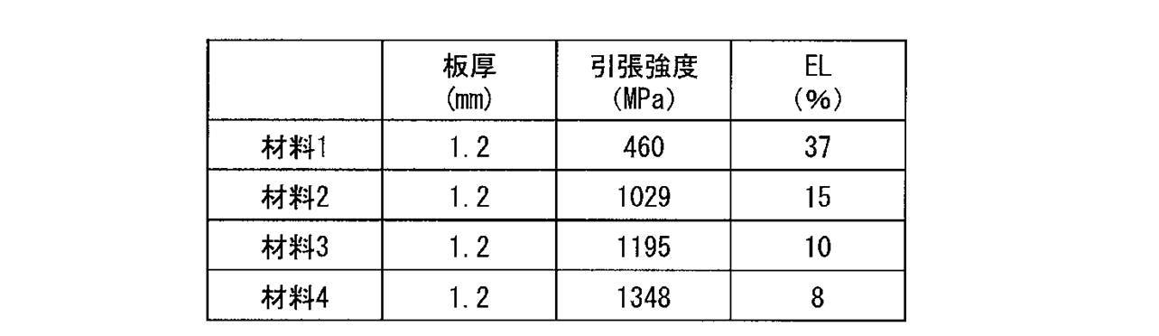

図19Aおよび図19Bに示す製品形状を得るために、図33に示す金属板54を中間形状を経ることなくプレス成形(絞り成形)することにより、図34に示す成形形状の成形品55を製造した。より詳細には、ダイとしわ押さえによって金属板の外縁部を拘束し、ポンチを押し込むことで絞り成形を行った。金属板は、表1に示す板厚、引張強度及び伸び(EL)を有する3種類(材料1~3)の鋼板を用いた。成形後の成形品について、割れの有無を目視で調べた。結果を表3に示す。 (Comparative Example 3)
In order to obtain the product shape shown in FIGS. 19A and 19B, the
図19A、図19Bに示す製品形状と図20に示す仮の金属板24の形状をもとに、実施形態1において説明した手順で、成形前の仮想金属板25の形状と中間形状を求め、成形前の仮想金属板25の形状の表1に示す板厚、引張強度及び伸び(EL)を有する3種類(材料1~3)の鋼板について、中間形状に成形した後に成形形状に成形した。 (Example 5)
Based on the product shape shown in FIGS. 19A and 19B and the shape of the
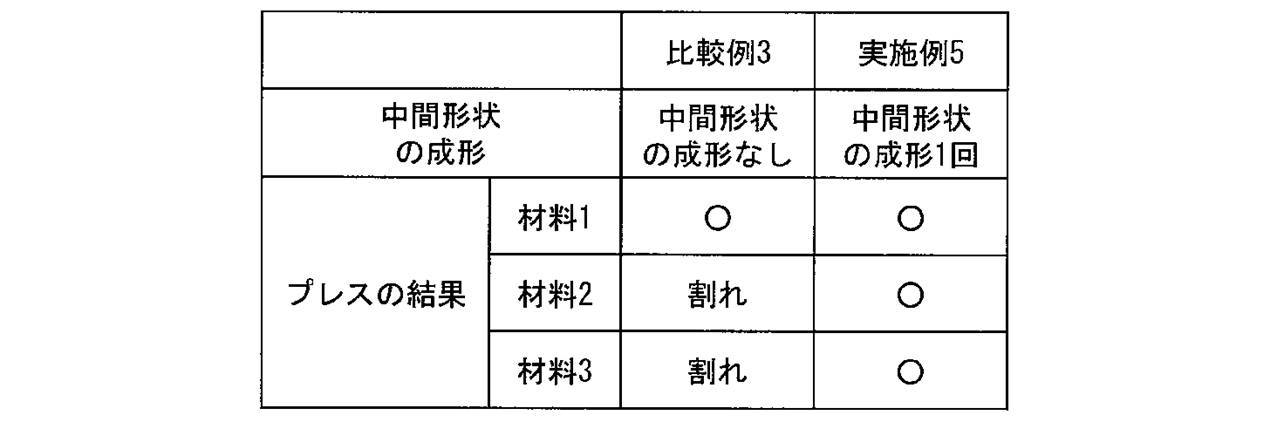
Claims (35)
- 金属板をプレス成形して成形形状に成形する際に、前記金属板を成形形状とは異なる中間形状に成形し、次いで、前記中間形状から前記成形形状に成形する金属板の成形方法であって、
前記金属板から前記中間形状を成形する際に、前記金属板から前記成形形状に直接成形する場合よりも前記中間形状を経て前記成形形状に成形する場合の方が、前記金属板からの板厚減少率が大きい部位の少なくとも一部を含む第1の領域を成形することにより、前記中間形状を成形する
金属板の成形方法。 When forming a metal plate into a molded shape by press molding, the metal plate is molded into an intermediate shape different from the molded shape, and then formed from the intermediate shape to the molded shape. ,
When forming the intermediate shape from the metal plate, the thickness from the metal plate is greater when forming the molded shape through the intermediate shape than when forming directly from the metal plate into the molded shape. A method for forming a metal plate, wherein the intermediate shape is formed by forming a first region including at least a part of a portion having a large reduction rate. - 下記第1ステップと下記第2ステップとを順次行うことにより求められた有限要素法解析における成形形状の金属板の要素データ(B)と成形前の仮想金属板の要素データ(D)をもとに、
前記成形前の仮想金属板の要素データ(D)のうち前記第1の領域に対応する一部の要素には、前記一部の要素の各要素に対応する前記成形形状の金属板の要素データ(B)の各要素の形状に変形するのに必要なひずみを与え、
前記成形前の仮想金属板の要素データ(D)のうち前記中間形状を経て前記成形形状に成形する場合よりも前記金属板から前記成形形状に直接成形する場合の方が前記金属板からの板厚減少率が大きい部位の少なくとも一部を含む第2の領域に対応する残りの要素には、前記残りの要素の各要素に対応する前記成形形状の金属板の要素データ(B)の各要素の形状に変形するのに必要なひずみより絶対値の小さなひずみを与えるかまたはひずみを与えずに、
前記成形前の仮想金属板を変形させた場合の変形後の仮想金属板の要素データ(G)の形状を前記中間形状とする、請求項1記載の金属板の成形方法。
第1ステップ:仮の金属板の要素データ(A)および前記成形形状の金属板の要素データ(B)を用意するステップ。
第2ステップ:前記仮の金属板の要素データ(A)と前記成形形状の金属板の要素データ(B)の、対応する各要素間の形状の差が小さくなるように前記仮の金属板の要素データ(A)を修正して成形前の仮想金属板の要素データ(D)を求めるステップ。 Based on the element data (B) of the shaped metal plate and the element data (D) of the virtual metal plate before forming in the finite element method analysis obtained by sequentially performing the following first step and the following second step. In addition,
Among the element data (D) of the virtual metal plate before forming, some elements corresponding to the first region include element data of the metal plate having the forming shape corresponding to each element of the partial element. (B) giving the strain necessary to deform into the shape of each element,
Of the element data (D) of the virtual metal plate before forming, the plate formed from the metal plate is directly formed from the metal plate into the formed shape rather than formed into the formed shape through the intermediate shape. The remaining elements corresponding to the second region including at least a part of the portion where the thickness reduction rate is large include each element of the element data (B) of the shaped metal plate corresponding to each element of the remaining element Either give a strain whose absolute value is smaller than the strain required to deform into the shape of
The metal plate forming method according to claim 1, wherein the shape of element data (G) of the virtual metal plate after deformation when the virtual metal plate before forming is deformed is the intermediate shape.
1st step: The step which prepares the element data (A) of a temporary metal plate, and the element data (B) of the metal plate of the said shaping | molding shape.
Second step: The provisional metal plate's element data (A) and the shape-formed metal plate's element data (B) are reduced so that the difference in shape between corresponding elements becomes small. Correcting the element data (A) to obtain element data (D) of the virtual metal plate before forming; - 前記第1ステップは、有限要素法による成形解析により、仮の金属板の要素データ(A)をもとに、前記成形形状の金属板の要素データ(B)を求める
請求項2記載の金属板の成形方法。 The metal plate according to claim 2, wherein the first step obtains element data (B) of the shaped metal plate based on element data (A) of the temporary metal plate by forming analysis using a finite element method. Molding method. - 前記第1ステップは、有限要素法による逆解析により、前記成形形状の金属板の要素データ(B)をもとに、前記仮の金属板の要素データ(A)を求める
請求項2記載の金属板の成形方法。 3. The metal according to claim 2, wherein the first step obtains element data (A) of the temporary metal plate based on element data (B) of the shaped metal plate by inverse analysis using a finite element method. A method of forming a plate. - 前記第2ステップにおいて、下記第2-1ステップ、下記第2-2ステップ及び下記第2-3ステップを順次行うことにより、
前記仮の金属板の要素データ(A)と前記成形形状の金属板の要素データ(B)の、対応する各要素間の形状の差が小さくなるように前記仮の金属板の要素データ(A)を修正して成形前の仮想金属板の要素データ(D)を求めることを特徴とする請求項2乃至請求項4の何れか1項に記載の金属板の成形方法。
第2-1ステップ:前記仮の金属板の要素データ(A)の各要素に対応する前記成形形状の金属板の要素データ(B)の各要素の形状に弾性変形させるために必要な、前記仮の金属板の要素データ(A)の各要素に印加する応力(F1)を前記仮の金属板の要素データ(A)の各要素毎に求めるステップ。
第2-2ステップ:前記仮の金属板の要素データ(A)の各要素に、絶対値が前記第2-1ステップにおいて求めた前記応力(F1)以上の応力(F2)を与えるとともに、各有限要素の節点の面外方向への変位を拘束する条件を与えた有限要素モデル(I)を作成するステップ。
第2-3ステップ:前記第2-2のステップで作成した有限要素モデル(I)をもとに有限要素法による弾性変形解析を行い、弾性変形後の要素データ(H)を求め、前記仮の金属板の要素データ(A)の各有限要素の形状を、弾性変形後の有限要素データ(H)の各有限要素の形状となるように修正し、修正した有限要素データを成形前の仮想金属板の要素データ(D)とするステップ。 In the second step, by sequentially performing the following 2-1 step, the following 2-2 step, and the following 2-3 step,
The element data (A) of the temporary metal plate so that the difference in shape between corresponding elements of the element data (A) of the temporary metal plate and the element data (B) of the metal plate of the formed shape is reduced. 5) to obtain element data (D) of the virtual metal plate before forming, the metal plate forming method according to any one of claims 2 to 4.
Step 2-1: Necessary for elastically deforming to the shape of each element of the element data (B) of the shaped metal plate corresponding to each element of the element data (A) of the temporary metal plate, Obtaining a stress (F1) to be applied to each element of the element data (A) of the temporary metal plate for each element of the element data (A) of the temporary metal sheet;
Step 2-2: Each element of the element data (A) of the temporary metal plate is given a stress (F2) whose absolute value is greater than or equal to the stress (F1) obtained in the step 2-1 and A step of creating a finite element model (I) that gives a condition for constraining a displacement of a finite element node in an out-of-plane direction.
Step 2-3: Elastic deformation analysis by the finite element method is performed based on the finite element model (I) created in the step 2-2, and element data (H) after elastic deformation is obtained. The shape of each finite element of the element data (A) of the metal plate is corrected so as to be the shape of each finite element of the finite element data (H) after elastic deformation, and the corrected finite element data is virtual before forming. A step of setting element data (D) of the metal plate. - 前記応力(F2)は、絶対値が前記応力(F1)より大きく且つ前記応力(F1)の1.5倍以下の応力である
請求項5記載の金属板の成形方法。 The method for forming a metal plate according to claim 5, wherein the stress (F2) is a stress having an absolute value larger than the stress (F1) and not more than 1.5 times the stress (F1). - 前記成形前の仮想金属板の要素データ(D)の各要素に対応する前記成形形状の金属板の要素データ(B)の各要素の形状に弾性変形するのに必要な応力(F3)を、前記成形前の仮想金属板の要素データ(D)の各要素毎に求め、
前記成形前の仮想金属板の要素データ(D)の一部の要素には前記弾性変形するのに必要な応力(F3)を与えるとともに、前記成形前の仮想金属板の要素データ(D)の残りの要素には前記弾性変形するのに必要な応力(F3)より絶対値の小さな応力を与えるかまたは応力を与えない有限要素モデル(J)を作成し、
前記有限要素モデル(J)をもとに、有限要素法による弾性変形解析を行うことにより、
前記成形前の仮想金属板の要素データ(D)の一部の要素には、前記一部の要素に対応する前記成形形状の金属板の要素データ(B)の各要素の形状に変形するのに必要なひずみを与え、
前記成形前の仮想金属板の要素データ(D)の残りの要素には、前記残りの要素に対応する前記成形形状の金属板の要素データ(B)の各要素の形状に変形するのに必要なひずみより絶対値の小さなひずみを与えるかまたはひずみを与えずに、
変形させた場合の変形後の仮想金属板の要素データ(G)を求める、
ことを特徴とする請求項2乃至請求項6の何れか一項に記載の金属板の成形方法。 Stress (F3) required to elastically deform into the shape of each element in the element data (B) of the metal plate of the shaped shape corresponding to each element of the element data (D) of the virtual metal plate before forming, Obtained for each element of element data (D) of the virtual metal plate before forming,
A stress (F3) necessary for the elastic deformation is applied to a part of the element data (D) of the virtual metal plate before forming, and the element data (D) of the virtual metal plate before forming is applied. For the remaining elements, a finite element model (J) is created in which a stress having an absolute value smaller than the stress necessary for elastic deformation (F3) or no stress is created,
Based on the finite element model (J), by performing elastic deformation analysis by the finite element method,
A part of the element data (D) of the virtual metal plate before forming is transformed into the shape of each element of the element data (B) of the metal plate of the forming shape corresponding to the part of the element. To give the necessary strain
The remaining elements of the element data (D) of the virtual metal plate before forming are necessary to transform into the shape of each element of the element data (B) of the metal plate of the forming shape corresponding to the remaining elements. Either give a strain whose absolute value is smaller than the normal strain or
Obtaining the element data (G) of the virtual metal plate after deformation when it is deformed,
The method for forming a metal plate according to any one of claims 2 to 6, wherein the metal plate is formed. - 前記成形前の仮想金属板の要素データ(D)の残りの要素のうち、前記一部の要素との境界近傍の要素には絶対値が前記応力(F3)より小さな応力を与え、前記境界近傍の要素から離れるにつれ徐々に絶対値が小さくなる応力を前記残りの要素に与える
請求項7記載の金属板の成形方法。 Among the remaining elements of the element data (D) of the virtual metal plate before forming, the elements in the vicinity of the boundary with the partial elements are given stress whose absolute value is smaller than the stress (F3), and the vicinity of the boundary The method for forming a metal plate according to claim 7, wherein a stress whose absolute value gradually decreases as the distance from the element is reduced is applied to the remaining elements. - 前記第2ステップにおいて得られた前記成形前の仮想金属板の要素データ(D)を前記第1ステップにおける前記仮の金属板の要素データ(A)と置換してから、前記第1ステップおよび前記第2ステップを行う、または、前記第2ステップを行って成形前の仮想金属板の要素データ(D)を求め直すことを特徴とする請求項2乃至請求項8の何れか一項に記載の金属板の成形方法。 After replacing the element data (D) of the pre-forming virtual metal plate obtained in the second step with the element data (A) of the temporary metal plate in the first step, the first step and the The second step is performed, or the element data (D) of the virtual metal plate before forming is re-determined by performing the second step, and the second step is performed. Metal plate forming method.
- 前記成形前の仮想金属板の要素データ(D)と前記成形形状の金属板の要素データ(B)との間において対応する各要素の成形前後での状態変化量(ΔX)の上限の閾値、または、上限の閾値および下限の閾値を設定し、
前記状態変化量(ΔX)の上限の閾値のみを設定した場合は、状態変化量(ΔX)の最大値が閾値以下の要素データになるまで、
前記状態変化量(ΔX)の上限および下限の閾値を設定した場合は、状態変化量(ΔX)の最大値および最小値が上限の閾値以下でかつ下限の閾値以上の要素データになるまで、
前記第2ステップにおいて得られた前記成形前の仮想金属板の要素データ(D)を前記第1ステップにおける前記仮の金属板の要素データ(A)と置換してから、前記第1ステップおよび前記第2ステップまたは前記第2ステップを行って成形前の仮想金属板の要素データ(D)を求め直すことを繰り返すことを特徴とする請求項2乃至請求項9の何れか一項に記載の金属板の成形方法。 The upper limit threshold value of the state change amount (ΔX) before and after forming each corresponding element between the element data (D) of the virtual metal plate before forming and the element data (B) of the metal plate having the formed shape, Or set the upper and lower thresholds,
When only the upper limit threshold of the state change amount (ΔX) is set, until the maximum value of the state change amount (ΔX) becomes element data equal to or less than the threshold value,
When the upper limit and lower limit thresholds of the state change amount (ΔX) are set, until the maximum value and the minimum value of the state change amount (ΔX) are equal to or lower than the upper limit threshold and become element data equal to or higher than the lower limit threshold,
After replacing the element data (D) of the pre-forming virtual metal plate obtained in the second step with the element data (A) of the temporary metal plate in the first step, the first step and the The metal according to any one of claims 2 to 9, wherein the second step or the second step is repeated to re-determine element data (D) of the virtual metal plate before forming. A method of forming a plate. - 金属板をプレス成形して成形形状に成形する際に、前記金属板を成形形状とは異なる複数の中間形状に順次成形し、最後の中間形状から前記成形形状に成形する金属板の成形方法であって、
前記複数の中間形状を得る工程および前記成形形状を得る工程のうち、全部もしくは一部の工程において、請求項1~10の何れか一項に記載の成形方法で得られた形状を、前記工程の前工程で成形する中間形状とする、金属板の成形方法。 When a metal plate is press-molded into a molded shape, the metal plate is sequentially formed into a plurality of intermediate shapes different from the molded shape, and the metal plate is formed from the last intermediate shape to the molded shape. There,
The shape obtained by the molding method according to any one of claims 1 to 10 in the whole or a part of the step of obtaining the plurality of intermediate shapes and the step of obtaining the molded shape, A metal plate forming method in which the intermediate shape is formed in the previous step. - 金属板をプレス成形して成形形状に成形する際に、前記金属板を成形形状とは異なる中間形状に成形し、次いで、前記中間形状から前記成形形状に成形する場合の前記中間形状の設計方法であって、
前記金属板から前記中間形状を成形する際に、前記金属板から前記成形形状に直接成形する場合よりも前記中間形状を経て前記成形形状に成形する場合の方が、前記金属板からの板厚減少率が大きい部位の少なくとも一部を含む第1の領域を成形した場合の形状を、前記中間形状とする
中間形状の設計方法。 When the metal plate is press-molded into a molded shape, the metal plate is molded into an intermediate shape different from the molded shape, and then the intermediate shape is designed from the intermediate shape to the molded shape. Because
When forming the intermediate shape from the metal plate, the thickness from the metal plate is greater when forming the molded shape through the intermediate shape than when forming directly from the metal plate into the molded shape. A method for designing an intermediate shape, wherein a shape when the first region including at least a part of a portion having a large reduction rate is formed is the intermediate shape. - 下記第1ステップと下記第2ステップとを順次行うことにより求められた有限要素法解析における成形形状の金属板の要素データ(B)と成形前の仮想金属板の要素データ(D)をもとに、
前記成形前の仮想金属板の要素データ(D)のうち前記第1の領域に対応する一部の要素には、前記一部の要素の各要素に対応する前記成形形状の金属板の要素データ(B)の各要素の形状に変形するのに必要なひずみを与え、
前記成形前の仮想金属板の要素データ(D)のうち前記中間形状を経て前記成形形状に成形する場合よりも前記金属板から前記成形形状に直接成形する場合の方が前記金属板からの板厚減少率が大きい部位の少なくとも一部を含む第2の領域に対応する残りの要素には、前記残りの要素の各要素に対応する前記成形形状の金属板の要素データ(B)の各要素の形状に変形するのに必要なひずみより絶対値の小さなひずみを与えるかまたはひずみを与えずに、
前記成形前の仮想金属板を変形させた場合の変形後の仮想金属板の要素データ(G)の形状を前記中間形状とする、請求項11記載の中間形状の設計方法。
第1ステップ:仮の金属板の要素データ(A)および前記成形形状の金属板の要素データ(B)を用意するステップ。
第2ステップ:前記仮の金属板の要素データ(A)と前記成形形状の金属板の要素データ(B)のトポロジー的に対応する各要素間の形状の差が小さくなるように前記仮の金属板の要素データ(A)を修正して成形前の仮想金属板の要素データ(D)を求めるステップ。 Based on the element data (B) of the shaped metal plate and the element data (D) of the virtual metal plate before forming in the finite element method analysis obtained by sequentially performing the following first step and the following second step. In addition,
Among the element data (D) of the virtual metal plate before forming, some elements corresponding to the first region include element data of the metal plate having the forming shape corresponding to each element of the partial element. (B) giving the strain necessary to deform into the shape of each element,
Of the element data (D) of the virtual metal plate before forming, the plate formed from the metal plate is directly formed from the metal plate into the formed shape rather than formed into the formed shape through the intermediate shape. The remaining elements corresponding to the second region including at least a part of the portion where the thickness reduction rate is large include each element of the element data (B) of the shaped metal plate corresponding to each element of the remaining element Either give a strain whose absolute value is smaller than the strain required to deform into the shape of
The intermediate shape design method according to claim 11, wherein the shape of element data (G) of the virtual metal plate after deformation when the virtual metal plate before forming is deformed is the intermediate shape.
1st step: The step which prepares the element data (A) of a temporary metal plate, and the element data (B) of the metal plate of the said shaping | molding shape.
Second step: The temporary metal so that the difference in shape between the topologically corresponding elements of the element data (A) of the temporary metal plate and the element data (B) of the metal plate of the formed shape is small. Correcting the element data (A) of the plate to obtain the element data (D) of the virtual metal plate before forming; - 前記第1ステップは、有限要素法による成形解析により、仮の金属板の要素データ(A)をもとに、前記成形形状の金属板の要素データ(B)を求める
請求項13記載の中間形状の設計方法。 The intermediate shape according to claim 13, wherein the first step obtains element data (B) of the shaped metal plate based on element data (A) of the temporary metal plate by forming analysis using a finite element method. Design method. - 前記第1ステップは、有限要素法による逆解析により、前記成形形状の金属板の要素データ(B)をもとに、前記仮の金属板の要素データ(A)を求める
請求項13記載の中間形状の設計方法。 The intermediate | middle of Claim 13 WHEREIN: The said 1st step calculates | requires the element data (A) of the said temporary metal plate based on the element data (B) of the metal plate of the said shaping | molding by the reverse analysis by a finite element method. Shape design method. - 前記第2ステップにおいて、下記第2-1ステップ、下記第2-2ステップ及び下記第2-3ステップを順次行うことにより、
前記仮の金属板の要素データ(A)と前記成形形状の金属板の要素データ(B)の、対応する各要素間の形状の差が小さくなるように前記仮の金属板の要素データ(A)を修正して成形前の仮想金属板の要素データ(D)を求めることを特徴とする請求項13乃至請求項15の何れか1項に記載の中間形状の設計方法。
第2-1ステップ:前記仮の金属板の要素データ(A)の各要素をトポロジー的に対応
する前記成形形状の金属板の要素データ(B)の各要素の形状に弾性変形させるために必要な、前記仮の金属板の要素データ(A)の各要素に印加する応力(F1)を前記仮の金属板の要素データ(A)の各要素毎に求めるステップ。
第2-2ステップ:前記仮の金属板の要素データ(A)の各要素に、絶対値が前記第2-1ステップにおいて求めた前記応力(F1)以上の応力(F2)を与えるとともに、各有限要素の節点の面外方向への変位を拘束する条件を与えた有限要素モデル(I)を作成するステップ。
第2-3ステップ:前記第2-2のステップで作成した有限要素モデル(I)をもとに有限要素法による弾性変形解析を行い、弾性変形後の要素データ(H)を求め、前記仮の金属板の要素データ(A)の各有限要素の形状を、弾性変形後の有限要素データ(H)の各有限要素の形状となるように修正し、修正した有限要素データを成形前の仮想金属板の要素データ(D)とするステップ。 In the second step, by sequentially performing the following 2-1 step, the following 2-2 step, and the following 2-3 step,
The element data (A) of the temporary metal plate so that the difference in shape between corresponding elements of the element data (A) of the temporary metal plate and the element data (B) of the metal plate of the formed shape is reduced. The intermediate shape design method according to any one of claims 13 to 15, wherein the element data (D) of the virtual metal plate before forming is obtained by correcting (1).
Step 2-1: Necessary for elastically deforming each element of the element data (A) of the temporary metal plate to the shape of each element of the element data (B) of the shaped metal plate corresponding to the topological shape The step of obtaining the stress (F1) applied to each element of the element data (A) of the temporary metal plate for each element of the element data (A) of the temporary metal sheet.
Step 2-2: Each element of the element data (A) of the temporary metal plate is given a stress (F2) whose absolute value is greater than or equal to the stress (F1) obtained in the step 2-1 and A step of creating a finite element model (I) that gives a condition for constraining a displacement of a finite element node in an out-of-plane direction.
Step 2-3: Elastic deformation analysis by the finite element method is performed based on the finite element model (I) created in the step 2-2, and element data (H) after elastic deformation is obtained. The shape of each finite element of the element data (A) of the metal plate is corrected so as to be the shape of each finite element of the finite element data (H) after elastic deformation, and the corrected finite element data is virtual before forming. A step of setting element data (D) of the metal plate. - 前記応力(F2)は、絶対値が前記応力(F1)より大きく且つ前記応力(F1)の1.5倍以下の応力である
請求項16記載の中間形状の設計方法。 The intermediate shape design method according to claim 16, wherein the stress (F2) is a stress having an absolute value larger than the stress (F1) and not more than 1.5 times the stress (F1). - 前記成形前の仮想金属板の要素データ(D)の各要素に対応する前記成形形状の金属板の要素データ(B)の各要素の形状に弾性変形するのに必要な応力(F3)を、前記成形前の仮想金属板の要素データ(D)の各要素毎に求め、
前記成形前の仮想金属板の要素データ(D)の一部の要素には前記弾性変形するのに必要な応力(F3)を与えるとともに、前記成形前の仮想金属板の要素データ(D)の残りの要素には前記弾性変形するのに必要な応力(F3)より絶対値の小さな応力を与えるかまたは応力を与えない有限要素モデル(J)を作成し、
前記有限要素モデル(J)をもとに、有限要素法による弾性変形解析を行うことにより、
前記成形前の仮想金属板の要素データ(D)の一部の要素には、前記一部の要素に対応する前記成形形状の金属板の要素データ(B)の各要素の形状に変形するのに必要なひずみを与え、
前記成形前の仮想金属板の要素データ(D)の残りの要素には、前記残りの要素に対応する前記成形形状の金属板の要素データ(B)の各要素の形状に変形するのに必要なひずみより絶対値の小さなひずみを与えるかまたはひずみを与えずに、
変形させた場合の変形後の仮想金属板の要素データ(G)を求める、
ことを特徴とする請求項13乃至請求項17の何れか一項に記載の中間形状の設計方法。 Stress (F3) required to elastically deform into the shape of each element in the element data (B) of the metal plate of the shaped shape corresponding to each element of the element data (D) of the virtual metal plate before forming, Obtained for each element of element data (D) of the virtual metal plate before forming,
A stress (F3) necessary for the elastic deformation is applied to a part of the element data (D) of the virtual metal plate before forming, and the element data (D) of the virtual metal plate before forming is applied. For the remaining elements, a finite element model (J) is created in which a stress having an absolute value smaller than the stress necessary for elastic deformation (F3) or no stress is created,
Based on the finite element model (J), by performing elastic deformation analysis by the finite element method,
A part of the element data (D) of the virtual metal plate before forming is transformed into the shape of each element of the element data (B) of the metal plate of the forming shape corresponding to the part of the element. To give the necessary strain
The remaining elements of the element data (D) of the virtual metal plate before forming are necessary to transform into the shape of each element of the element data (B) of the metal plate of the forming shape corresponding to the remaining elements. Either give a strain whose absolute value is smaller than the normal strain or
Obtaining the element data (G) of the virtual metal plate after deformation when it is deformed,
The intermediate shape design method according to any one of claims 13 to 17, wherein the intermediate shape is designed. - 前記成形前の仮想金属板の要素データ(D)の残りの要素のうち、前記一部の要素との境界近傍の要素には絶対値が前記応力(F3)より小さな応力を与え、前記境界近傍の要素から離れるにつれ徐々に絶対値が小さくなる応力を前記残りの要素に与える
請求項18記載の中間形状の設計方法。 Among the remaining elements of the element data (D) of the virtual metal plate before forming, the elements in the vicinity of the boundary with the partial elements are given stress whose absolute value is smaller than the stress (F3), and the vicinity of the boundary The intermediate shape design method according to claim 18, wherein a stress whose absolute value gradually decreases as the distance from the element is reduced is applied to the remaining elements. - 前記第2ステップにおいて得られた前記成形前の仮想金属板の要素データ(D)を前記第1ステップにおける前記仮の金属板の要素データ(A)と置換してから、前記第1ステップおよび前記第2ステップを行う、または、前記第2ステップを行って成形前の仮想金属板の要素データ(D)を求め直すことを特徴とする請求項13乃至請求項19の何れか一項に記載の中間形状の設計方法。 After replacing the element data (D) of the pre-forming virtual metal plate obtained in the second step with the element data (A) of the temporary metal plate in the first step, the first step and the The second step is performed, or the element data (D) of the virtual metal plate before forming is recalculated by performing the second step, and according to any one of claims 13 to 19, Intermediate shape design method.
- 前記成形前の仮想金属板の要素データ(D)と前記成形形状の金属板の要素データ(B)との間においてトポロジー的に対応する各有限要素の成形前後での状態変化量(ΔX)の上限の閾値、または、上限の閾値および下限の閾値を設定し、
前記状態変化量(ΔX)の上限の閾値のみを設定した場合は、状態変化量(ΔX)の最大値が閾値以下の要素データになるまで、
前記状態変化量(ΔX)の上限および下限の閾値を設定した場合は、状態変化量(ΔX)の最大値および最小値が上限の閾値以下でかつ下限の閾値以上の要素データになるまで、
前記第2ステップにおいて得られた前記成形前の仮想金属板の要素データ(D)を前記第1ステップにおける前記仮の金属板の要素データ(A)と置換してから、前記第1ステップおよび前記第2ステップまたは前記第2ステップを行って成形前の仮想金属板の要素データ(D)を求め直すことを繰り返すことを特徴とする請求項13乃至請求項19の何れか一項に記載の中間形状の設計方法。 The state change amount (ΔX) before and after forming each finite element topologically corresponding between the element data (D) of the virtual metal plate before forming and the element data (B) of the metal plate having the formed shape Set the upper threshold, or the upper and lower thresholds,
When only the upper limit threshold of the state change amount (ΔX) is set, until the maximum value of the state change amount (ΔX) becomes element data equal to or less than the threshold value,
When the upper limit and lower limit thresholds of the state change amount (ΔX) are set, until the maximum value and the minimum value of the state change amount (ΔX) are equal to or lower than the upper limit threshold and become element data equal to or higher than the lower limit threshold,
After replacing the element data (D) of the pre-forming virtual metal plate obtained in the second step with the element data (A) of the temporary metal plate in the first step, the first step and the The intermediate according to any one of claims 13 to 19, wherein the second step or the second step is repeated to obtain the element data (D) of the virtual metal plate before forming again. Shape design method. - 金属板をプレス成形して成形形状に成形する際に、前記金属板を成形形状とは異なる複数の中間形状に順次成形し、最後の中間形状から前記成形形状に成形する場合の前記中間形状の設計方法において、
前記複数の中間形状を得る工程および前記成形形状を得る工程のうち、全部もしくは一部の工程において、請求項12~21の何れか一項に記載の設計方法で得られた形状を、前記工程の前工程で成形する中間形状とする、中間形状の設計方法。 When the metal plate is press-molded into a molded shape, the metal plate is sequentially molded into a plurality of intermediate shapes different from the molded shape, and the intermediate shape in the case of forming from the last intermediate shape to the molded shape. In the design method,
The shape obtained by the design method according to any one of claims 12 to 21 in all or a part of the step of obtaining the plurality of intermediate shapes and the step of obtaining the molded shape, An intermediate shape design method in which the intermediate shape is formed in the previous step. - 請求項1~11の何れか一項に記載の金属板の成形方法において得られた中間形状を、ダイフェース面の形状として含むことを特徴とする金属板の成形用金型。 A metal plate molding die comprising an intermediate shape obtained by the method for molding a metal plate according to any one of claims 1 to 11 as a shape of a die face surface.
- 金属板をプレス成形して成形形状に成形する際に、前記金属板を成形形状とは異なる中間形状に成形し、次いで、前記中間形状から前記成形形状に成形する場合に前記中間形状を設計するためのコンピュータプログラムであって、
コンピュータに、
前記金属板から前記中間形状を成形する際に、前記金属板から前記成形形状に直接成形する場合よりも前記中間形状を経て前記成形形状に成形する場合の方が、前記金属板からの板厚減少率が大きい部位の少なくとも一部を含む第1の領域を成形した場合の形状を、前記中間形状とするステップ
を含む処理を実行させるためのコンピュータプログラム。 When the metal plate is press-molded into a molded shape, the metal plate is formed into an intermediate shape different from the molded shape, and then the intermediate shape is designed when forming from the intermediate shape to the molded shape. A computer program for
On the computer,
When forming the intermediate shape from the metal plate, the thickness from the metal plate is greater when forming the molded shape through the intermediate shape than when forming directly from the metal plate into the molded shape. A computer program for executing a process including a step of setting a shape when a first region including at least a part of a portion having a large decrease rate is formed as the intermediate shape. - 有限要素法解析における、仮の金属板の要素データ(A)と、前記仮の金属板の要素データ(A)に対応する成形形状の金属板の要素データ(B)をもとに、
下記第2-1ステップと下記第2-2ステップを順次行うことにより、
前記仮の金属板の要素データ(A)と前記成形形状の金属板の要素データ(B)との各要素間の形状の差が小さくなるように前記仮の金属板の要素データ(A)を修正して成形前の仮想金属板の要素データ(D)を求めるための有限要素法による弾性変形解析を行うための有限要素モデル(I)を作成することを含む請求項24記載のコンピュータプログラム。
第2-1ステップ:前記仮の金属板の要素データ(A)の各要素を、前記成形形状の金属板の要素データ(B)の各要素の形状に弾性変形させるために必要な、前記仮の金属板の要素データ(A)の各要素に印加する応力(F1)を前記仮の金属板の要素データ(A)の各要素毎に求めるステップ。
第2-2ステップ:前記仮の金属板の要素データ(A)の各要素に、絶対値が前記第2-1ステップにおいて求めた前記応力(F1)以上の応力(F2)を与えるとともに、各有限要素の節点の面外方向への変位を拘束する条件を与えた有限要素モデル(I)を作成するステップ。 Based on the element data (A) of the temporary metal plate in the finite element method analysis and the element data (B) of the shaped metal plate corresponding to the element data (A) of the temporary metal plate,
By sequentially performing the following step 2-1 and step 2-2,
The element data (A) of the temporary metal plate is reduced so that the difference in shape between the elements of the element data (A) of the temporary metal plate and the element data (B) of the metal plate of the formed shape is reduced. The computer program according to claim 24, further comprising: creating a finite element model (I) for performing elastic deformation analysis by a finite element method for correcting and obtaining element data (D) of the virtual metal plate before forming.
Step 2-1: The temporary metal plate element data (A) required for elastically deforming each element of the shaped metal plate element data (B) into the shape of each element. Obtaining a stress (F1) applied to each element of the element data (A) of the metal plate for each element of the element data (A) of the temporary metal plate.
Step 2-2: Each element of the element data (A) of the temporary metal plate is given a stress (F2) whose absolute value is greater than or equal to the stress (F1) obtained in the step 2-1 and A step of creating a finite element model (I) that gives a condition for constraining a displacement of a finite element node in an out-of-plane direction. - 有限要素法解析における、仮の金属板の要素データ(A)と仮の金属板の要素データ(A)とトポロジー的に同相な成形形状の金属板の要素データ(B)をもとに、
下記第2-1ステップ、下記第2-2ステップ及び下記2-3ステップを順次行うことにより、
前記仮の金属板の要素データ(A)と前記成形形状の金属板の要素データ(B)のトポロジー的に対応する各要素間の形状の差が小さくなるように前記仮の金属板の要素データ(A)を修正して成形前の仮想金属板の要素データ(D)を求めることを含む請求項24記載のコンピュータプログラム。
第2-1ステップ:前記仮の金属板の要素データ(A)の各要素をトポロジー的に対応
する前記成形形状の金属板の要素データ(B)の各要素の形状に弾性変形させるために必要な、前記仮の金属板の要素データ(A)の各要素に印加する応力(F1)を前記仮の金属板の要素データ(A)の各要素毎に求めるステップ。
第2-2ステップ:前記仮の金属板の要素データ(A)の各要素に、絶対値が前記第2-1ステップにおいて求めた前記応力(F1)以上の応力(F2)を与えるとともに、各有限要素の節点の面外方向への変位を拘束する条件を与えた有限要素モデル(I)を作成するステップ。
第2-3ステップ:前記有限要素モデル(I)をもとに有限要素法による弾性変形解析を行い、弾性変形後の要素データ(H)を求め、前記仮の金属板の要素データ(A)の各有限要素の形状を、弾性変形後の有限要素データ(H)の各有限要素の形状となるように修正し、修正した有限要素データを成形前の仮想金属板の要素データ(D)とするステップ。 Based on the element data (A) of the temporary metal plate and the element data (A) of the temporary metal plate in the finite element method analysis based on the element data (B) of the shaped metal plate that is topologically in phase,
By sequentially performing the following 2-1 step, the following 2-2 step and the following 2-3 step,
Element data of the temporary metal plate so that the difference in shape between topologically corresponding elements of the element data (A) of the temporary metal plate and the element data (B) of the metal plate of the formed shape is reduced. 25. The computer program according to claim 24, comprising correcting (A) to obtain element data (D) of a virtual metal plate before forming.
Step 2-1: Necessary for elastically deforming each element of the element data (A) of the temporary metal plate to the shape of each element of the element data (B) of the shaped metal plate corresponding to the topological shape The step of obtaining the stress (F1) applied to each element of the element data (A) of the temporary metal plate for each element of the element data (A) of the temporary metal sheet.
Step 2-2: Each element of the element data (A) of the temporary metal plate is given a stress (F2) whose absolute value is greater than or equal to the stress (F1) obtained in the step 2-1 and A step of creating a finite element model (I) that gives a condition for constraining a displacement of a finite element node in an out-of-plane direction.
Step 2-3: Elastic deformation analysis by the finite element method is performed based on the finite element model (I) to obtain element data (H) after elastic deformation, and element data (A) of the temporary metal plate The shape of each finite element is corrected to be the shape of each finite element of the finite element data (H) after elastic deformation, and the corrected finite element data is converted to the element data (D) of the virtual metal plate before forming. Step to do. - 前記応力(F2)は、絶対値が前記応力(F1)より大きく且つ前記応力(F1)の1.5倍以下の応力である
請求項25又は請求項26記載のコンピュータプログラム。 27. The computer program according to claim 25, wherein the stress (F2) is a stress having an absolute value larger than the stress (F1) and not more than 1.5 times the stress (F1). - 有限要素法解析における、成形前の仮想金属板の要素データ(D)と、前記成形前の仮想金属板の要素データ(D)に対応する成形形状の金属板の要素データ(B)をもとに、
前記成形前の仮想金属板の要素データ(D)の各要素が、前記成形前の仮想金属板の要素データ(D)の各要素に対応する前記成形形状の金属板の要素データ(B)の各要素の形状に弾性変形するのに必要な応力(F3)を各要素毎に求め、
前記成形前の仮想金属板の要素データ(D)のうち前記第1の領域に対応する一部の要素には前記弾性変形するのに必要な応力(F3)を与えるとともに、前記成形前の仮想金属板の要素データ(D)のうち中間形状を経て前記成形形状に成形する場合よりも前記金属板から前記成形形状に直接成形する場合の方が前記金属板からの板厚減少率が大きい部位の少なくとも一部を含む第2の領域に対応する残りの要素には前記弾性変形するのに必要な応力(F3)より絶対値の小さな応力を与えるかまたは応力を与えない有限要素モデル(J)を作成することを含む請求項25~請求項27の何れか1項に記載のコンピュータプログラム。 Based on element data (D) of a virtual metal plate before forming and element data (B) of a metal plate having a shape corresponding to the element data (D) of the virtual metal plate before forming in the finite element method analysis In addition,
Each element of the element data (D) of the virtual metal plate before forming corresponds to each element of the element data (D) of the virtual metal plate before forming. Obtain stress (F3) required for elastic deformation to the shape of each element for each element,
Among the element data (D) of the virtual metal plate before forming, a part of the elements corresponding to the first region is given stress (F3) necessary for the elastic deformation, and the virtual data before forming Of the element data (D) of the metal plate, the portion where the plate thickness reduction rate from the metal plate is larger when the metal plate is directly formed into the formed shape than when the metal plate is formed into the formed shape through an intermediate shape A finite element model (J) in which the remaining element corresponding to the second region including at least a part of the stress is given a stress having an absolute value smaller than the stress (F3) necessary for the elastic deformation or no stress. The computer program according to any one of claims 25 to 27, comprising creating - 前記有限要素モデル(J)をもとに、有限要素法による弾性変形解析を行うことにより、
前記成形前の仮想金属板の要素データ(D)のうち前記第1の領域に対応する一部の要素には、前記一部の要素の各要素に対応する前記成形形状の金属板の要素データ(B)の各要素の形状に変形するのに必要なひずみを与え、
前記成形前の仮想金属板の要素データ(D)のうち前記第2の領域に対応する残りの要素には、前記残りの要素の各要素に対応する前記成形形状の金属板の要素データ(B)の各要素の形状に変形するのに必要なひずみより絶対値の小さなひずみを与えるかまたはひずみを与えずに、
前記成形前の仮想金属板を変形させた場合の変形後の仮想金属板の要素データ(G)を求める、
ことを含む請求項28記載のコンピュータプログラム。 Based on the finite element model (J), by performing elastic deformation analysis by the finite element method,
Among the element data (D) of the virtual metal plate before forming, some elements corresponding to the first region include element data of the metal plate having the forming shape corresponding to each element of the partial element. (B) giving the strain necessary to deform into the shape of each element,
Of the element data (D) of the virtual metal plate before forming, the remaining elements corresponding to the second region include element data (B of the metal plate having the forming shape corresponding to each element of the remaining elements. ) Strain with absolute value less than the strain required to transform into the shape of each element or without strain,
Obtaining element data (G) of the virtual metal plate after deformation when the virtual metal plate before forming is deformed,
29. The computer program according to claim 28. - 前記成形前の仮想金属板の要素データ(D)の残りの要素のうち、前記一部の要素との境界近傍の要素には絶対値が前記応力(F3)より小さな応力を与え、前記境界近傍の要素から離れるにつれ徐々に絶対値が小さくなる応力を前記残りの要素に与える
請求項28又は請求項29記載のコンピュータプログラム。 Among the remaining elements of the element data (D) of the virtual metal plate before forming, the elements in the vicinity of the boundary with the partial elements are given stress whose absolute value is smaller than the stress (F3), and the vicinity of the boundary 30. The computer program according to claim 28, wherein stress is applied to the remaining elements as the absolute value thereof gradually decreases as the distance from the element increases. - 有限要素法による成形解析により、仮の金属板を成形形状に成形する際の前記仮の金属板の要素データ(A)、前記成形形状の金属板の要素データ(B)を求める第1ステップと、
前記有限要素モデル(J)をもとに、有限要素法による弾性変形解析を行うことにより、前記中間形状とする第3ステップと、
を実行させるための請求項28乃至請求項30の何れか一項に記載のコンピュータプログラム。 A first step of obtaining element data (A) of the temporary metal plate and element data (B) of the metal plate of the formed shape when forming the temporary metal plate into a formed shape by forming analysis by a finite element method; ,
Based on the finite element model (J), by performing elastic deformation analysis by a finite element method, the third step to the intermediate shape,
The computer program according to any one of claims 28 to 30, wherein the computer program is executed. - 前記第2-3ステップにおいて得られた前記成形前の仮想金属板の要素データ(D)を前記第1ステップにおける前記仮の金属板の要素データ(A)と置換してから、前記第1ステップ~前記第2-3ステップ、または、前記第2-1ステップ~前記第2-3ステップを順次行って成形前の仮想金属板の要素データ(D)を求め直すことをコンピュータに実行させることを特徴とする請求項31に記載のコンピュータプログラム。 The element data (D) of the pre-forming virtual metal plate obtained in the 2-3 step is replaced with the element data (A) of the temporary metal plate in the first step, and then the first step. -Causing the computer to recalculate the element data (D) of the virtual metal plate before forming by sequentially performing the 2-3 step or the 2-1 step to the 2-3 step. 32. A computer program according to claim 31 characterized in that
- 前記成形前の仮想金属板の要素データ(D)と前記成形形状の金属板の要素データ(B)との間において対応する各要素の成形前後での状態変化量(ΔX)の上限の閾値、または、上限の閾値および下限の閾値を設定し、
前記状態変化量(ΔX)の上限の閾値のみを設定した場合は、状態変化量(ΔX)の最大値が閾値以下の要素データになるまで、
前記状態変化量(ΔX)の上限および下限の閾値を設定した場合は、状態変化量(ΔX)の最大値および最小値が上限の閾値以下でかつ下限の閾値以上の要素データになるまで、
前記第2-3ステップにおいて得られた前記成形前の仮想金属板の要素データ(D)を前記第1ステップにおける前記仮の金属板の要素データ(A)と置換してから、前記第1ステップ~前記第2-3ステップもしくは前記第2-1ステップ~前記第2-3ステップを行って成形前の仮想金属板の要素データ(D)を求め直すことを繰り返すことを特徴とする請求項31または請求項32に記載のコンピュータプログラム。 The upper limit threshold value of the state change amount (ΔX) before and after forming each corresponding element between the element data (D) of the virtual metal plate before forming and the element data (B) of the metal plate having the formed shape, Or set the upper and lower thresholds,
When only the upper limit threshold of the state change amount (ΔX) is set, until the maximum value of the state change amount (ΔX) becomes element data equal to or less than the threshold value,
When the upper limit and lower limit thresholds of the state change amount (ΔX) are set, until the maximum value and the minimum value of the state change amount (ΔX) are equal to or lower than the upper limit threshold and become element data equal to or higher than the lower limit threshold,
The element data (D) of the virtual metal plate before forming obtained in the 2-3 step is replaced with the element data (A) of the temporary metal plate in the first step, and then the first step. 32. Repeatedly obtaining the element data (D) of the virtual metal plate before forming by performing the step 2-3 or the step 2-1 to the step 2-3. Or the computer program of Claim 32. - 金属板をプレス成形して成形形状に成形する際に、前記金属板を成形形状とは異なる複数の中間形状に順次成形し、最後の中間形状から前記成形形状に成形する際の前記中間形状を求めるコンピュータプログラムであって、
コンピュータに、
請求項31乃至請求項33の何れか一項に記載のコンピュータプログラムにおいて求められた形状を中間形状に置き換えて、前記第1ステップから前記第3ステップを順次行う請求項31乃至請求項33の何れか一項に記載のコンピュータプログラム。 When the metal plate is press-molded into a molded shape, the metal plate is sequentially formed into a plurality of intermediate shapes different from the molded shape, and the intermediate shape when forming from the last intermediate shape to the molded shape is determined. A computer program for which
On the computer,
The shape obtained by the computer program according to any one of claims 31 to 33 is replaced with an intermediate shape, and the first step to the third step are sequentially performed. A computer program according to claim 1. - 請求項24乃至請求項34の何れか一項に記載のコンピュータプログラムを記録したコンピュータ読取可能な記録媒体。 A computer-readable recording medium on which the computer program according to any one of claims 24 to 34 is recorded.
Priority Applications (8)
| Application Number | Priority Date | Filing Date | Title |
|---|---|---|---|
| US16/471,442 US11270047B2 (en) | 2016-12-26 | 2017-12-25 | Metal sheet forming method, intermediate shape design method, metal sheet forming die, computer program, and recording medium |
| EP17889010.9A EP3560618A4 (en) | 2016-12-26 | 2017-12-25 | Metal plate forming method, intermediate shape designing method, metal plate forming mold, computer program, and recording medium |
| KR1020197016057A KR102225319B1 (en) | 2016-12-26 | 2017-12-25 | Metal plate molding method, intermediate shape design method, metal plate molding mold, computer program, and recording medium |
| CN201780078222.7A CN110087790B (en) | 2016-12-26 | 2017-12-25 | Method for molding metal plate, method for designing intermediate shape, mold for molding metal plate, computer program, and recording medium |
| MX2019007662A MX2019007662A (en) | 2016-12-26 | 2017-12-25 | Metal plate forming method, intermediate shape designing method, metal plate forming mold, computer program, and recording medium. |
| CA3046944A CA3046944A1 (en) | 2016-12-26 | 2017-12-25 | Metal sheet forming method, intermediate shape design method, metal sheet forming die, computer program, and recording medium |
| JP2018559472A JP6856078B2 (en) | 2016-12-26 | 2017-12-25 | Metal plate molding method, intermediate shape design method, metal plate molding mold, computer program, and recording medium |
| BR112019012411-0A BR112019012411A2 (en) | 2016-12-26 | 2017-12-25 | METAL PLATE CONFORMATION METHOD, INTERMEDIATE FORMAT DESIGN METHOD, METAL PLATE CONFORMATION MATRIX, COMPUTER PROGRAM AND RECORDING MEDIA |
Applications Claiming Priority (2)
| Application Number | Priority Date | Filing Date | Title |
|---|---|---|---|
| JP2016-251820 | 2016-12-26 | ||
| JP2016251820 | 2016-12-26 |
Publications (1)
| Publication Number | Publication Date |
|---|---|
| WO2018123989A1 true WO2018123989A1 (en) | 2018-07-05 |
Family
ID=62709427
Family Applications (1)
| Application Number | Title | Priority Date | Filing Date |
|---|---|---|---|
| PCT/JP2017/046477 WO2018123989A1 (en) | 2016-12-26 | 2017-12-25 | Metal plate forming method, intermediate shape designing method, metal plate forming mold, computer program, and recording medium |
Country Status (9)
| Country | Link |
|---|---|
| US (1) | US11270047B2 (en) |
| EP (1) | EP3560618A4 (en) |
| JP (1) | JP6856078B2 (en) |
| KR (1) | KR102225319B1 (en) |
| CN (1) | CN110087790B (en) |
| BR (1) | BR112019012411A2 (en) |
| CA (1) | CA3046944A1 (en) |
| MX (1) | MX2019007662A (en) |
| WO (1) | WO2018123989A1 (en) |
Cited By (3)
| Publication number | Priority date | Publication date | Assignee | Title |
|---|---|---|---|---|
| JP6996671B1 (en) * | 2020-09-02 | 2022-01-17 | Jfeスチール株式会社 | Manufacturing method of stamped parts, die design method, die shape design device, and die |
| JP7020599B1 (en) * | 2020-09-02 | 2022-02-16 | Jfeスチール株式会社 | Manufacturing method of stamped parts, die design method, die shape design device, and die |
| WO2022049904A1 (en) * | 2020-09-02 | 2022-03-10 | Jfeスチール株式会社 | Pressed component manufacturing method, mold designing method, mold shape designing device, and mold |
Families Citing this family (1)
| Publication number | Priority date | Publication date | Assignee | Title |
|---|---|---|---|---|
| KR20210155437A (en) * | 2020-06-15 | 2021-12-23 | 삼성디스플레이 주식회사 | Window molding apparatus and window molding method using the same |
Citations (6)
| Publication number | Priority date | Publication date | Assignee | Title |
|---|---|---|---|---|
| JP2007326112A (en) | 2006-06-06 | 2007-12-20 | Hiroshima Pref Gov | Press forming method |
| JP2010172916A (en) * | 2009-01-28 | 2010-08-12 | Jatco Ltd | Method and system for forming workpiece |
| JP4879588B2 (en) | 2006-01-19 | 2012-02-22 | 新日本製鐵株式会社 | Metal plate press molding method for automobile parts having a tensile strength of 440 MPa or more for suppressing spring back |
| JP2015110237A (en) * | 2013-12-06 | 2015-06-18 | 新日鐵住金株式会社 | Device and method for press forming |
| WO2015115348A1 (en) * | 2014-01-28 | 2015-08-06 | Jfeスチール株式会社 | Press molding method, manufacturing method for press-molded component, and method for determining preform shape for use in said methods |
| JP2016104492A (en) * | 2014-11-20 | 2016-06-09 | Jfeスチール株式会社 | Press molding method |
Family Cites Families (13)
| Publication number | Priority date | Publication date | Assignee | Title |
|---|---|---|---|---|
| WO2000053349A1 (en) * | 1999-03-10 | 2000-09-14 | Ishikawajima-Harima Heavy Industries Co., Ltd. | Device and method for manufacturing hot-rolled sheet steel and device and method for sheet thickness pressing used for the device and method |
| JP2006247661A (en) * | 2005-03-08 | 2006-09-21 | Nok Corp | Projection portion working method, and work having projection portion |
| CN101213033B (en) * | 2005-06-30 | 2013-05-08 | 新日铁住金株式会社 | Method and device for designing member, computer program, and computer-readable recording medium |
| JP4697086B2 (en) * | 2005-12-01 | 2011-06-08 | 日産自動車株式会社 | Molded part having bent corners, manufacturing method thereof and manufacturing apparatus |
| US20090272171A1 (en) * | 2008-05-05 | 2009-11-05 | Ford Global Technologies, Llc | Method of designing and forming a sheet metal part |
| CN102581126B (en) * | 2012-02-28 | 2014-10-01 | 昆山三景科技股份有限公司 | Stamping die and method for circular convex hull on backboard of flat display |
| CN104220185B (en) * | 2012-04-16 | 2017-09-26 | 杰富意钢铁株式会社 | The manufacture method of the method for making of stamping forming limit line chart, fracturing shape method and punching parts |
| JP5884194B2 (en) * | 2013-07-17 | 2016-03-15 | Jfeスチール株式会社 | Press molding method and press molding apparatus |
| US20170140081A1 (en) * | 2014-07-30 | 2017-05-18 | Nippon Steel & Sumitomo Metal Corporation | Model setting method, forming simulation method, production method of forming tool, program, computer-readable recording medium having program recorded thereon, and finite element model |
| JP6418995B2 (en) * | 2015-03-18 | 2018-11-07 | 国立大学法人岩手大学 | Press forming method |
| CN106140901A (en) * | 2015-03-31 | 2016-11-23 | 株式会社日立制作所 | Sheet metal bending forming control method |
| TWI610733B (en) * | 2015-07-06 | 2018-01-11 | Nippon Steel & Sumitomo Metal Corp | Stamping part manufacturing method and manufacturing device |
| CN105149455B (en) * | 2015-09-28 | 2017-04-05 | 华南理工大学 | A kind of vertical stilling well drawing forming method and its mould |
-
2017
- 2017-12-25 US US16/471,442 patent/US11270047B2/en active Active
- 2017-12-25 BR BR112019012411-0A patent/BR112019012411A2/en not_active Application Discontinuation
- 2017-12-25 WO PCT/JP2017/046477 patent/WO2018123989A1/en active Application Filing
- 2017-12-25 CN CN201780078222.7A patent/CN110087790B/en active Active
- 2017-12-25 EP EP17889010.9A patent/EP3560618A4/en active Pending
- 2017-12-25 KR KR1020197016057A patent/KR102225319B1/en active IP Right Grant
- 2017-12-25 CA CA3046944A patent/CA3046944A1/en not_active Abandoned
- 2017-12-25 JP JP2018559472A patent/JP6856078B2/en active Active
- 2017-12-25 MX MX2019007662A patent/MX2019007662A/en unknown
Patent Citations (6)
| Publication number | Priority date | Publication date | Assignee | Title |
|---|---|---|---|---|
| JP4879588B2 (en) | 2006-01-19 | 2012-02-22 | 新日本製鐵株式会社 | Metal plate press molding method for automobile parts having a tensile strength of 440 MPa or more for suppressing spring back |
| JP2007326112A (en) | 2006-06-06 | 2007-12-20 | Hiroshima Pref Gov | Press forming method |
| JP2010172916A (en) * | 2009-01-28 | 2010-08-12 | Jatco Ltd | Method and system for forming workpiece |
| JP2015110237A (en) * | 2013-12-06 | 2015-06-18 | 新日鐵住金株式会社 | Device and method for press forming |
| WO2015115348A1 (en) * | 2014-01-28 | 2015-08-06 | Jfeスチール株式会社 | Press molding method, manufacturing method for press-molded component, and method for determining preform shape for use in said methods |
| JP2016104492A (en) * | 2014-11-20 | 2016-06-09 | Jfeスチール株式会社 | Press molding method |
Non-Patent Citations (1)
| Title |
|---|
| See also references of EP3560618A4 |
Cited By (4)
| Publication number | Priority date | Publication date | Assignee | Title |
|---|---|---|---|---|
| JP6996671B1 (en) * | 2020-09-02 | 2022-01-17 | Jfeスチール株式会社 | Manufacturing method of stamped parts, die design method, die shape design device, and die |
| JP7020599B1 (en) * | 2020-09-02 | 2022-02-16 | Jfeスチール株式会社 | Manufacturing method of stamped parts, die design method, die shape design device, and die |
| WO2022049904A1 (en) * | 2020-09-02 | 2022-03-10 | Jfeスチール株式会社 | Pressed component manufacturing method, mold designing method, mold shape designing device, and mold |
| WO2022049905A1 (en) * | 2020-09-02 | 2022-03-10 | Jfeスチール株式会社 | Method for producing pressed component, method for designing die, die shape designing device, and die |
Also Published As
| Publication number | Publication date |
|---|---|
| EP3560618A1 (en) | 2019-10-30 |
| US20200311325A1 (en) | 2020-10-01 |
| KR102225319B1 (en) | 2021-03-09 |
| CA3046944A1 (en) | 2018-07-05 |
| JPWO2018123989A1 (en) | 2019-11-07 |
| KR20190084073A (en) | 2019-07-15 |
| CN110087790A (en) | 2019-08-02 |
| CN110087790B (en) | 2021-04-30 |
| BR112019012411A2 (en) | 2020-02-27 |
| MX2019007662A (en) | 2019-09-04 |
| JP6856078B2 (en) | 2021-04-07 |
| EP3560618A4 (en) | 2020-09-09 |
| US11270047B2 (en) | 2022-03-08 |
Similar Documents
| Publication | Publication Date | Title |
|---|---|---|
| WO2018123989A1 (en) | Metal plate forming method, intermediate shape designing method, metal plate forming mold, computer program, and recording medium | |
| JP6191846B2 (en) | PRESS MOLDING METHOD, METHOD FOR PRODUCING PRESS MOLDED PARTS, AND METHOD FOR DETERMINING PREFORMED SHAPE USED FOR THEM | |
| JP2006289480A (en) | Press forming method and metal mold used for the same | |
| JP6123951B2 (en) | Blank shape determination method, blank manufacturing method, press molding method, press molded product manufacturing method, computer program, and recording medium | |
| JP6098664B2 (en) | Shear edge molding availability evaluation method | |
| JP6512191B2 (en) | Method of designing mold and method of manufacturing press-formed product | |
| JP2009104456A (en) | Model design system | |
| JP2017013090A (en) | Manufacturing method for press formed product having hat-shaped cross-sectional shape and preliminary formed product formed by the same manufacturing method | |
| JP2008119736A (en) | Press forming die device and press forming method | |
| WO2019167792A1 (en) | Production method for pressed components, press molding device, and metal plate for press molding | |
| JP2014161911A (en) | Press-forming method | |
| JP6665837B2 (en) | Manufacturing method of press-formed product | |
| JP2005266892A (en) | Mold designing support system and method, and program for supporting mold designing | |
| JP2017006943A (en) | Press molding product manufacturing method | |
| JP2010005651A (en) | Die for press forming of metallic member of hat-shaped section, and press forming method thereof | |
| EP3747566A1 (en) | Press molding method, rigidity-improved-position specifying method, press-molding system, and press-molded product | |
| JP4660637B2 (en) | Press molding system | |
| JP2020093303A (en) | Method of manufacturing press component, and design method for lower die | |
| JP2020069534A (en) | Manufacturing method of press part, and design method of lower mold | |
| JP2006281281A (en) | Forming process decision apparatus, forming process decision program, forming process decision method, and formability determination apparatus, formability determination program, and formability determination method | |
| Lin et al. | Compensation of Contour Distortion in Stretch-Flanging Metal Sheets | |
| JP7409583B1 (en) | Manufacturing method of press molded products | |
| WO2021125290A1 (en) | Method for manufacturing press-formed product, press-forming device, and press-forming line | |
| JP4576322B2 (en) | Shape correction method, mold, and method of manufacturing molded product | |
| KR20200067879A (en) | Press forming method of sheet |
Legal Events
| Date | Code | Title | Description |
|---|---|---|---|
| 121 | Ep: the epo has been informed by wipo that ep was designated in this application |
Ref document number: 17889010 Country of ref document: EP Kind code of ref document: A1 |
|
| ENP | Entry into the national phase |
Ref document number: 20197016057 Country of ref document: KR Kind code of ref document: A |
|
| ENP | Entry into the national phase |
Ref document number: 3046944 Country of ref document: CA |
|
| ENP | Entry into the national phase |
Ref document number: 2018559472 Country of ref document: JP Kind code of ref document: A |
|
| REG | Reference to national code |
Ref country code: BR Ref legal event code: B01A Ref document number: 112019012411 Country of ref document: BR |
|
| NENP | Non-entry into the national phase |
Ref country code: DE |
|
| WWE | Wipo information: entry into national phase |
Ref document number: 2017889010 Country of ref document: EP Ref document number: 2019119706 Country of ref document: RU |
|
| ENP | Entry into the national phase |
Ref document number: 112019012411 Country of ref document: BR Kind code of ref document: A2 Effective date: 20190617 |