WO2018123601A1 - Forceps robot - Google Patents
Forceps robot Download PDFInfo
- Publication number
- WO2018123601A1 WO2018123601A1 PCT/JP2017/044785 JP2017044785W WO2018123601A1 WO 2018123601 A1 WO2018123601 A1 WO 2018123601A1 JP 2017044785 W JP2017044785 W JP 2017044785W WO 2018123601 A1 WO2018123601 A1 WO 2018123601A1
- Authority
- WO
- WIPO (PCT)
- Prior art keywords
- rotary actuator
- claw
- gripper
- housing
- pair
- Prior art date
Links
Images


Classifications
-
- A—HUMAN NECESSITIES
- A61—MEDICAL OR VETERINARY SCIENCE; HYGIENE
- A61B—DIAGNOSIS; SURGERY; IDENTIFICATION
- A61B34/00—Computer-aided surgery; Manipulators or robots specially adapted for use in surgery
- A61B34/30—Surgical robots
-
- B—PERFORMING OPERATIONS; TRANSPORTING
- B25—HAND TOOLS; PORTABLE POWER-DRIVEN TOOLS; MANIPULATORS
- B25J—MANIPULATORS; CHAMBERS PROVIDED WITH MANIPULATION DEVICES
- B25J9/00—Programme-controlled manipulators
- B25J9/10—Programme-controlled manipulators characterised by positioning means for manipulator elements
- B25J9/14—Programme-controlled manipulators characterised by positioning means for manipulator elements fluid
- B25J9/146—Rotary actuators
-
- A—HUMAN NECESSITIES
- A61—MEDICAL OR VETERINARY SCIENCE; HYGIENE
- A61B—DIAGNOSIS; SURGERY; IDENTIFICATION
- A61B17/00—Surgical instruments, devices or methods, e.g. tourniquets
- A61B17/28—Surgical forceps
-
- A—HUMAN NECESSITIES
- A61—MEDICAL OR VETERINARY SCIENCE; HYGIENE
- A61B—DIAGNOSIS; SURGERY; IDENTIFICATION
- A61B17/00—Surgical instruments, devices or methods, e.g. tourniquets
- A61B17/28—Surgical forceps
- A61B17/29—Forceps for use in minimally invasive surgery
-
- B—PERFORMING OPERATIONS; TRANSPORTING
- B25—HAND TOOLS; PORTABLE POWER-DRIVEN TOOLS; MANIPULATORS
- B25J—MANIPULATORS; CHAMBERS PROVIDED WITH MANIPULATION DEVICES
- B25J15/00—Gripping heads and other end effectors
- B25J15/02—Gripping heads and other end effectors servo-actuated
- B25J15/0206—Gripping heads and other end effectors servo-actuated comprising articulated grippers
- B25J15/024—Gripping heads and other end effectors servo-actuated comprising articulated grippers having fingers directly connected to actuator
-
- B—PERFORMING OPERATIONS; TRANSPORTING
- B25—HAND TOOLS; PORTABLE POWER-DRIVEN TOOLS; MANIPULATORS
- B25J—MANIPULATORS; CHAMBERS PROVIDED WITH MANIPULATION DEVICES
- B25J15/00—Gripping heads and other end effectors
- B25J15/08—Gripping heads and other end effectors having finger members
-
- A—HUMAN NECESSITIES
- A61—MEDICAL OR VETERINARY SCIENCE; HYGIENE
- A61B—DIAGNOSIS; SURGERY; IDENTIFICATION
- A61B17/00—Surgical instruments, devices or methods, e.g. tourniquets
- A61B2017/00535—Surgical instruments, devices or methods, e.g. tourniquets pneumatically or hydraulically operated
- A61B2017/00539—Surgical instruments, devices or methods, e.g. tourniquets pneumatically or hydraulically operated hydraulically
-
- A—HUMAN NECESSITIES
- A61—MEDICAL OR VETERINARY SCIENCE; HYGIENE
- A61B—DIAGNOSIS; SURGERY; IDENTIFICATION
- A61B34/00—Computer-aided surgery; Manipulators or robots specially adapted for use in surgery
- A61B34/30—Surgical robots
- A61B34/35—Surgical robots for telesurgery
-
- A—HUMAN NECESSITIES
- A61—MEDICAL OR VETERINARY SCIENCE; HYGIENE
- A61B—DIAGNOSIS; SURGERY; IDENTIFICATION
- A61B34/00—Computer-aided surgery; Manipulators or robots specially adapted for use in surgery
- A61B34/30—Surgical robots
- A61B34/37—Master-slave robots
Definitions
- the present invention relates to a robot forceps that opens and closes a gripper using hydraulic pressure.
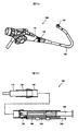
- Patent Literature 1 discloses a robot forceps 100 that opens and closes the gripper 103 using hydraulic pressure as shown in FIG. 7A. The robot forceps 100 is manually operated.
- the robot forceps 100 shown in FIG. 7A includes an operation unit main body 101, an insertion tube 102, and a gripper 103.
- the operation unit main body 101 is provided with an opening / closing operation unit 104 for the gripper 103.
- the gripper 103 is connected to a piston 110 that slides in the guide cylinder 120 as shown in FIG. 7B. That is, the piston 110 and the guide tube 120 are disposed in the distal end portion of the insertion tube 102.
- the opening / closing operation unit 104 is provided with a cylindrical body 140.
- the cylinder 140 and the guide cylinder 120 are connected by a tube 130 that passes through the insertion tube 102.
- a cylinder 150 is disposed in the cylindrical body 140, a small diameter portion of the pusher 160 is inserted into the cylinder 150, and a large diameter portion of the pusher 160 is exposed from the cylindrical body 140.
- the piston 110 is moved forward or backward to open and close the gripper 103. For this reason, when the gripper 103 is opened and closed, in addition to the linearly moving piston 110, a mechanism for converting this linear motion into a rotational motion for opening and closing the gripper 103 is required. Therefore, the robot forceps 100 is increased in size.
- an object of the present invention is to provide a robot forceps that can be made smaller than before.
- the robot forceps of the present invention includes an insertion tube and a gripper provided at a tip of the insertion tube, and the gripper includes a first claw portion and a first claw portion disposed to face each other. A second claw portion; and a first rotary actuator that is connected to the first claw portion and rotationally drives the first claw portion by supplying hydraulic fluid into the first pressure chamber.
- the gripper can be opened and closed by changing the distance between the first claw part and the second claw part that are arranged to face each other by rotationally driving the first claw part by the rotary actuator. it can.
- the robot forceps can be made smaller than before.
- the robot forceps may include a second rotary actuator that is connected to the second claw portion and rotationally drives the second claw portion by supplying hydraulic fluid into the second pressure chamber.
- the gripper can be opened and closed by rotationally driving the first claw portion and the second claw portion by the first rotary actuator and the second rotary actuator.
- the grippers are provided not only on the front side of the insertion tube but also on both sides in the rotation direction of the first claw portion and the second claw portion. The opening / closing position of can be changed.
- the first rotary actuator includes a first shaft portion, a first housing having a fan-shaped first recess, a first lid covering the first recess, the first recess, and the first lid.
- the first space formed by the first pressure chamber is divided into a pair of first pressure chambers, and has a first vane that rotates around the first shaft portion by the pressure of the hydraulic fluid
- the second rotary actuator has a second A second space formed by the shaft, a second housing having a fan-shaped second depression, a second lid covering the second depression, and the second depression and the second lid forms a pair of the second pressures.
- the first and second housings may be integrally formed with a second vane that is divided into chambers and rotates about the second shaft portion by the pressure of the hydraulic fluid. According to this structure, size reduction and cost reduction can be achieved by forming the first housing and the second housing integrally.
- the robot forceps further includes a wrist portion interposed between the insertion tube and the gripper, and the wrist portion rotationally drives the gripper with respect to the insertion tube by supplying hydraulic fluid into a third pressure chamber.
- the third rotary actuator may be included. According to this configuration, the gripper can be bent (inclined) with respect to the insertion tube by rotationally driving the gripper with respect to the insertion tube by the third rotary actuator.
- the third rotary actuator includes a third shaft portion, a third housing having a fan-shaped third recess, a third lid covering the third recess, the third recess, and the third lid.
- the third space is divided into a pair of third pressure chambers, and has a third vane that rotates around the third shaft portion by the pressure of the hydraulic fluid, and the third housing is fixed to the gripper.
- the wrist part may include a support part fixed to the third shaft part and connected to the insertion tube. According to this structure, the 3rd housing fixed to the gripper rotates with respect to the support part to which the 3rd axial part was fixed. Thereby, a gripper can be bent (inclined) with respect to the insertion tube connected to a support part.
- the third space is opposite to the first claw portion and the second claw portion with respect to the third shaft portion, and the third space is partitioned by the third vane.
- Each of the third pressure chambers is connected to each of the third pressure chambers, passes through the insertion pipe and passes between the support portion and the third rotary actuator, and passes through the insertion pipe. You may further provide a pair of piping each connected with a road part.
- connection portion between the pipe and the flow path portion can be disposed at a position close to the third shaft portion.
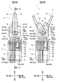
- FIG. 3A is a cross-sectional view of the robot forceps cut along line AA in FIG. 3A
- FIG. 4B is a front view of the robot forceps in FIG. 3A
- FIG. 4C is the robot forceps in FIG. 3B. It is the figure which looked at from the back side.
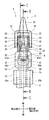
- FIG. 6A is a cross-sectional view of the robot forceps cut along line BB in FIG. 5, and FIG. 6B is a cross-sectional view of the robot forceps cut along line CC in FIG.
- FIG. 7A is a perspective view of a conventional robot forceps, and FIG. 7B is a cross-sectional view showing an internal structure of the conventional robot forceps.
- the axial direction of the insertion tube is referred to as the front-rear direction (the gripper side is the front and the drive unit side is the rear).
- the direction orthogonal to the front-rear direction is referred to as the first direction (the first claw portion side is the first a side and the second claw portion side is the first b side), and the direction orthogonal to the front-rear direction and the first direction is the first direction.
- Two directions (the first connecting portion side is referred to as the second a side, and the second connecting portion side is referred to as the second b side).
- the direction of the robot forceps is not limited to these directions and is arbitrary.
- FIG. 1 shows a robot forceps 1 according to the first embodiment of the present invention.
- the robot forceps 1 opens and closes the gripper 2 using the hydraulic pressure of the working fluid.
- the working fluid is not particularly limited, and examples thereof include water, physiological saline, and oil.
- the robot forceps 1 is used for a surgery support robot.
- the robot forceps 1 is attached to the manipulator of the slave side device and is remotely operated by the doctor on the master side device.
- the manipulator freely changes the posture of the robot forceps 1 so that a hole provided in the patient's skin serves as a fulcrum.
- the robot forceps 1 includes a drive unit 3, an insertion tube 4 that extends from the drive unit 3 and is inserted into a patient's body, and a gripper 2 that is provided at the distal end of the insertion tube 4 via a wrist portion 5. Including.
- the insertion tube 4 is a highly rigid tube that extends linearly.
- a pair of pipes 8 that connect the rotary actuators 30, 40, 60 of the gripper 2 and the wrist 5 and the drive unit 3 extend to the insertion pipe 4. Details of the gripper 2 and the wrist 5 will be described later.
- the drive unit 3 includes a supply / discharge mechanism 6 for operating the hydraulic fluid.
- the supply / discharge mechanism 6 supplies hydraulic fluid to the rotary actuators 30, 40, 60 through the one pipe 8 of the pair of pipes 8 when the pair of claw parts 21, 22 and the wrist part 5 are moved in one direction.
- the supply / discharge mechanism 6 supplies hydraulic fluid from the rotary actuators 30, 40, 60 through the other pipe 8 of the pair of pipes 8 when the pair of claw parts 21, 22 and the wrist part 5 are moved in the other direction.
- Discharge Each rotary actuator 30, 40, 60 has two pressure chambers, and the supply / discharge mechanism 6 is connected to each pressure chamber by a pipe 8. Therefore, the robot forceps 1 includes six supply / discharge mechanisms 6. It has been.
- the supply / discharge mechanism 6 includes a cylinder 6a to which a pipe 8 is connected, and a piston 6b disposed in the cylinder 6a.
- the cylinder 6a has a tubular portion that slidably holds the piston 6b and a front wall that closes the front opening of the tubular portion.
- a pressure chamber communicating with the pressure chambers of the rotary actuators 30, 40, 60 via the pipe 8 is formed between the piston 6 b and the front wall of the cylinder 6 a.
- the piston 6b is connected to the linear motion mechanism 7 by a rod 6c.
- the linear motion mechanism 7 is connected to the output shaft 72 of the motor 71, and converts the rotational motion of the output shaft 72 of the motor 71 into the linear motion of the rod 6c.
- the motor 71 is, for example, a servo motor.
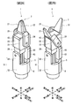
- the gripper 2 is shown in FIGS. 2A-6B.
- the gripper 2 holds, for example, an affected part and a suture needle.
- the gripper 2 includes a pair of claw portions (first claw portion 21 and second claw portion 22) and a first support portion 23.
- claw part 22 are arrange
- the first claw portion 21 is, for example, a triangular flat plate in plan view, the apex of which is forward, the base is spaced from the first support portion 23, and the first connecting portion 24 is used as the first support portion. 23.
- the first connecting part 24 extends from the bottom part of the first claw part 21 to the second direction 2a side, bends backward, and extends along the second side 2a side of the first support part 23 in the second direction.
- the rear portion of the first connecting portion 24 is connected to the first shaft portion 31 of the first rotary actuator 30.
- the second claw portion 22 is, for example, a triangular flat plate in a plan view, the apex thereof is forward, the base is spaced from the first support portion 23, and the first support portion is separated by the second connecting portion 25. 23.
- the second connecting portion 25 extends from the bottom of the second claw portion 22 to the second b side in the second direction, bends backward, and extends along the second b side surface of the first support portion 23 in the second direction.
- the rear portion of the second connecting portion 25 is connected to the second shaft portion 41 of the second rotary actuator 40.
- the first support portion 23 has a substantially rectangular parallelepiped main body.
- the first support portion 23 is provided with a first rotary actuator 30 and a second rotary actuator 40.
- the first rotary actuator 30 is connected to the first claw portion 21 and rotationally drives the first claw portion 21.
- the first rotary actuator 30 includes a first shaft portion 31, a first housing 32, a first lid 33, and a first vane 34.
- the 1st housing 32 is provided in the main body of the 1st support part 23, for example, is arranged at the 2a side of the 2nd direction of a main part.
- the first housing 32 is provided with a first recess 35 having a fan-shaped bottom surface (for example, a semicircular shape). In the first recess 35, the fan-shaped arc portion is in front of the straight portion, and the fan shape of the first recess 35 protrudes to the front gripper 2 side.
- the opening of the first recess 35 is covered with the first lid 33, whereby a first internal space is provided in the first housing 32.
- the first internal space is closer to the first and second claw portions 21 and 31 than the first shaft portion 31, and the first internal space is filled with hydraulic fluid.
- the first shaft portion 31 is provided at the fan-shaped center of the first recess 35, extends in the second direction, penetrates the first lid 33, and is connected to the first connecting portion 24 of the gripper 2.
- the first vane 34 is connected to the first shaft portion 31 in the first internal space.
- the first vane 34 is a plate-like body, extends from the first shaft portion 31 in the fan-shaped radial direction of the first recess 35, and passes through the first internal space through a pair of first pressure chambers (a first pressure chamber 36a and a first pressure chamber 36a). 1b pressure chamber 36b).
- the connection port of the 1a pressure chamber 36a is provided in the straight part of the 1st hollow 35, and is connected to the 1a channel part 37a.
- the first a flow path portion 37 a is provided in the main body of the first support portion 23, extends in the front-rear direction, and is connected to a first a pipe 81 a that passes through the insertion tube 4.
- the 1a flow path portion 37a and the 1a pipe 81a constitute a 1a pipe line, and the 1a pressure chamber 36a is connected to the supply / discharge mechanism 6 (FIG. 1) via the 1a pipe line.
- the connection port of the 1b pressure chamber 36b is provided in the straight part of the 1st hollow 35, and the 1b channel part 37b connects.
- the first b flow path portion 37 b is provided in the main body of the first support portion 23, extends in the front-rear direction, and is connected to the first b pipe 81 b that passes through the insertion pipe 4.
- the first b flow path portion 37b and the first b pipe 81b constitute a first b pipe line, and the first b pressure chamber 36b is connected to the supply / discharge mechanism 6 (FIG. 1) via the first b pipe line.
- the hydraulic fluid is supplied to the 1a and 1b pressure chambers 36a and 36b by the supply / discharge mechanism 6 via the 1a and 1b pipes.
- the first vane 34 rotates around the first shaft portion 31 due to the pressure difference of the hydraulic fluid between the first a pressure chamber 36a and the first b pressure chamber 36b.
- claw part 21 connected to the 1st vane 34 via the 1st axial part 31 moves.
- the second rotary actuator 40 is connected to the second claw portion 22 and rotationally drives the second claw portion 22.
- the second rotary actuator 40 includes a second shaft portion 41, a second housing 42, a second lid 43, and a second vane 44.
- the second internal space is formed by the second recess 45 and the second lid 43 of the second housing 42, and a pair of second pressure chambers (a second pressure chamber 46a and a second b pressure chamber 46b) by the second vane 44. It is divided into.
- the 2a flow path portion 47a connected to the 2a pressure chamber 46a and the 2a piping 82a connected to the 2a pressure chamber 46a constitute a 2a pipeline, and the 2a pressure chamber 46a is connected to the supply / exhaust mechanism 6 ( Connect to Figure 1).
- the second b flow path portion 47b connected to the second b pressure chamber 46b and the second b pipe 82b connected to the second b pressure chamber 46b constitute a second b pipe line, and the second b pressure chamber 46b passes through the second b pipe line, and the supply / discharge mechanism 6 ( Connect to Figure 1).
- the second rotary actuator 40 is disposed on the first support portion 23 symmetrically with the first rotary actuator 30 with respect to a plane orthogonal to the second direction. For this reason, since each part of the 2nd rotary actuator 40 is the same as each part of the 1st rotary actuator 30 except for plane symmetry, the explanation is omitted.
- first housing 32 and the second housing 42 arranged in plane symmetry in the first support portion 23 are integrally formed in the main body of the first support portion 23.
- the first shaft portion 31 and the second shaft portion 41 are arranged on the same straight line.
- the gripper 2 and the wrist 5 are shown in FIGS. 2A to 6B.
- the wrist part 5 is provided at the distal end of the insertion tube 4 and is a part connected to the gripper 2, and has a second support part 51 and a third rotary actuator 60.
- the second support portion 51 has a cylindrical portion 52 and a pair of extending portions 53, and the cylindrical portion 52 is attached to the distal end of the insertion tube 4.
- the extending portion 53 is a substantially plate-like body and extends forward from the cylindrical portion 52.
- the pair of extending portions 53 are disposed to face each other in the first direction, and a notch portion is provided between the pair of extending portions 53 along the circumferential direction of the cylindrical portion 52.
- the third rotary actuator 60 is fixed to the first support portion 23 of the gripper 2 and rotationally drives the gripper 2 with respect to the insertion tube 4.
- the third rotary actuator 60 has a third shaft portion 61, a third housing 62, a third lid 63, and a third vane 64.
- the third housing 62 has, for example, a rectangular parallelepiped shape, and the front surface thereof is connected to the rear surface of the first support portion 23 and is disposed between the pair of extending portions 53 and on the first b side in the first direction from the center thereof. Has been.
- the third housing 62 is provided with a third recess 65 whose bottom surface is fan-shaped (for example, semicircular).
- the fan-shaped arc portion is rearward of the straight portion, and the fan-shaped arc of the first recess 35 protrudes toward the rear insertion tube 4 side.
- the opening of the third recess 65 is covered with a third lid 63, whereby a third internal space is provided in the third housing 62.
- the third internal space is located on the opposite side to the first and second claw portions 21 and 31 side (insertion tube 4 side) with respect to the third shaft portion 61, and the third internal space is filled with hydraulic fluid.
- the third shaft portion 61 is provided at the fan-shaped center of the third recess 65, extends in the first direction, passes through the third housing 62 and the third lid 63, and is connected to each of the pair of extension portions 53.
- the third vane 64 is a plate-like body, one end of which is connected to the third shaft portion 61, extends from the third shaft portion 61 in the fan-shaped radial direction of the third recess 65, and passes through the third internal space.
- a pair of third pressure chambers (a 3a pressure chamber 66a and a 3b pressure chamber 66b) is partitioned.
- connection port of the 3a pressure chamber 66a is provided in the straight part of the 3rd hollow 65, and the 3a1 channel part (channel part) 67a1 connects.
- the third a1 flow path portion 67a1 is provided in the third housing 62, extends forward, and is connected to the third a2 flow path portion (flow path portion) 67a2.
- the third a2 flow path portion 67a2 is provided in the main body of the first support portion 23, extends forward from the rear end surface of the main body, bends in a U shape and extends rearward, and passes through the insertion tube 4 through a third a pipe (pipe) 83a. Connect to.
- the 3a1 flow path portion 67a1, the 3a2 flow path portion 67a2, and the 3a pipe 83a constitute a 3a pipe, and the 3a pressure chamber 66a is connected to the supply / discharge mechanism 6 (FIG. 1) via the 3a pipe. is doing.
- connection port of the 3b pressure chamber 66b is provided in the straight part of the 3rd hollow 65, and the 3b1 channel part (channel part) 67b1 connects.
- the third b1 flow path portion 67b1 is provided in the third housing 62, extends forward, and is connected to the third b2 flow path portion (flow path portion) 67b2.
- the third b2 flow path portion 67b2 is provided in the main body of the first support portion 23, extends forward from the rear end surface of the main body, bends in a U shape, extends rearward, and passes through the insertion tube 4 through a third b pipe (pipe) 83b. Connect to.
- the 3b1 flow path part 67b1, the 3b2 flow path part 67b2, and the 3b pipe 83b constitute a 3b pipe, and the 3b pressure chamber 66b is connected to the supply / discharge mechanism 6 (FIG. 1) via the 3b pipe. is doing.
- the third rotary actuator 60 is disposed on one side (second b side) of the second support portion 51, and the connection portion between the flow path portions 37a, 37b, 47a, 47b, 67a2, 67b2 of each pipe and the pipe 8. 26 is disposed on the other side (the second a side) of the second support portion 51.
- the pipe 8 includes a first a pipe 81a, a first b pipe 81b, a second a pipe 82a, a second b pipe 82b, a third a pipe 83a, and a third b pipe 83b.
- the piping 8 when it is not necessary to distinguish these, they may be simply referred to as the piping 8.
- the 1a piping 81a and the 1b piping 81b are a pair
- the 2a piping 82a and the 2b piping 82b are a pair
- the 3a piping 83a and the 3b piping 83b are a pair.
- the third rotary actuator 60 is disposed between the extending portion 53 on the 1b side of the second support portion 51 and the pipe 8 and the connection portion 26 thereof.
- the piping 8 and its connecting portion 26 are disposed between the extending portion 53 on the 1a side of the second support portion 51 and the third rotary actuator 60.
- the pipes 8 are parallel to each other and extend to the insertion pipe 4.
- the pair of pipes 8 arranged in the second direction has a center extending in the second direction in the second support part 51 and the insertion pipe 4 with the third shaft part 61 of the third rotary actuator 60 interposed therebetween. They are arranged symmetrically with respect to the line.
- the hydraulic fluid is supplied to or discharged from the first and second rotary actuators 30 and 40 of the gripper 2 through the pipes by the supply / discharge mechanism 6.
- the hydraulic fluid passes through each connection port through each pipeline and flows into each pressure chamber 36a, 36b, 46a, 46b of the first and second rotary actuators 30, 40, or flows out from each pressure chamber 36a, 36b, 46a, 46b. .
- the pressure of the hydraulic fluid is applied to the first and second vanes 34, 44 between the adjacent pressure chambers 36a, 36b, 46a, 46b, and the first pressure chamber 36a, 36b, 46a, 46b is caused by the pressure difference between the adjacent pressure chambers 36a, 36b, 46a, 46b.
- the 2nd vanes 34 and 44 rotate with the 1st and 2nd axial parts 31 and 41 connected to this.
- the first and second claw portions 21, 22 connected to the first and second shaft portions 31, 41 by the first and second connecting portions 24, 25 are connected to the first and second rotary actuators 30, It inclines with respect to the 1st support part 23 in which 40 was provided.
- the first and second internal spaces constituted by the adjacent pressure chambers 36a, 36b, 46a, 46b are semicircular.
- the first and second vanes 34 and 44 rotate about 180 ° in the first direction ( ⁇ about 90 ° with respect to the front-rear direction), and the first and second claw portions 21 and 22 connected to the first and second vanes 34 and 44 also move in the first direction. It is inclined about 180 ° in one direction. Note that about 180 ° is a value including 180 ° and a manufacturing error, and about 90 ° is a value including 90 ° and a manufacturing error.
- the first claw part 21 and the second claw part 22 that are inclined in this manner relatively move, so that the interval between the first claw part 21 and the second claw part 22 that are arranged to face each other is increased or decreased.
- a grasped object such as a body tissue or an instrument is sandwiched between the first claw part 21 and the second claw part 22. It can be gripped with.
- the grasped object sandwiched between the first claw part 21 and the second claw part 22 can be released. it can.
- the first claw portion 21 is driven by the first rotary actuator 30, and the second claw portion 22 is driven by the second rotary actuator 40.
- claw part 22 can also move independently, respectively, and can also move interlockingly.
- claw part 22 may fix one side, and only the other may move.
- the hydraulic fluid is supplied to or discharged from the third rotary actuator 60 of the wrist portion 5 through each pipeline in the insertion tube 4 by the supply / discharge mechanism 6.
- the hydraulic fluid passes through the connection ports through the pipes and flows into the pressure chambers 66a and 66b of the third rotary actuator 60 or flows out of the pressure chambers 66a and 66b.
- the pressure of the hydraulic fluid is applied to the third vane 64 between the adjacent pressure chambers 66a and 66b, and the third housing 62 constituting each pressure chamber 66a and 66b is formed by the pressure difference between the adjacent pressure chambers 66a and 66b. It rotates with respect to the 3 vane 64 and the 3rd axial part 61 connected to this.
- the first and second claw portions 21 and 22 connected to the third housing 62 via the first support portion 23 are inclined with respect to the third support portion connected to the third shaft portion 61.
- This inclination direction is a direction (second direction) perpendicular to the third shaft portion 61 extending in the first direction.
- the third housing 62 having the third internal space is about 180 ° ( ⁇ about relative to the front-rear direction). 90 °)
- the first and second claw portions 21 and 22 connected thereto are also inclined by about 180 °. Note that about 180 ° is a value including 180 ° and a manufacturing error, and about 90 ° is a value including 90 ° and a manufacturing error.
- the first and second rotary actuators 30 and 40 rotate and drive the first and second claw portions 21 and 22.
- claw parts 21 and 22 is unnecessary. Therefore, the robot forceps 1 can be reduced in size, for example, the robot forceps 1 can be used for surgery in a limited space in the body.
- first and second vanes 34 and 44 that drive the first and second claw portions 21 and 22 rotate in the first and second rotary actuators 30 and 40. For this reason, it is not necessary to separately provide a space for the first and second vanes 34 and 44 to operate. Therefore, the robot forceps 1 can be reduced in size.
- first and second claw portions 21 and 22 are connected to the shaft portions 31 and 41 of the first and second rotary actuators 30 and 40 that drive the first and second claw portions 21 and 22, respectively. Therefore, it is not necessary to provide a power transmission mechanism such as a wire and a pulley between the first and second claw portions 21 and 22 and the driving portion. For this reason, there is no loss of power of the first and second claw portions 21 and 22 due to friction in the power transmission mechanism, and a decrease in gripping force by the first and second claw portions 21 and 22 can be suppressed. Further, there is no deterioration of the power transmission mechanism such as wire wear due to the pulley, and a decrease in durability of the robot forceps 1 due to this deterioration can be suppressed.
- first and second claw portions 21 and 22 are inclined ⁇ 90 ° with respect to the front-rear direction by the first and second rotary actuators 30 and 40, and the movable range is wide. Moreover, the 1st nail
- first housing 32 and the second housing 42 are formed integrally with the main body of the first support portion 23. For this reason, it can hold down rather than a cost and a manufacturing process rather than the case where these are provided separately.
- the 3a2 and 3b2 flow path portions 67a2 and 67b2 are bent in a U-shape in the first direction, and the connection portion 26 between the 3a and 3b pipes 83a and 83b is the third rotary actuator 60 and the second support portion 51. It is arrange
- connection portion 26 between the flow path portion and the third and third b pipes 83 a and 83 b is located at the rear portion of the third rotary actuator 60 and is provided away from the third shaft portion 61. Therefore, when the third rotary actuator 60 is rotated and the wrist portion 5 is bent, the 3a and 3b pipes 83a and 83b extend from the third rotary actuator 60 in the second direction and then bend backward. It protrudes from the rotary actuator 60. Moreover, the difference of the length of 3a and 3b piping 83a, 83b with the case where the wrist part 5 is bent and the case where it is not bent is large.
- connection ports of the pressure chambers 66a and 66b of the third rotary actuator 60 are provided in the front, and the 3a2 and 3b2 flows connected to the connection ports via the 3a1 and 3b1 flow path portions 67b1.
- the path portions 67a2 and 67b2 are bent in a U shape and connected to the 3a and 3b pipes 83a and 83b.
- the connection portion 26 between the third a2 and third b2 flow path portions 67a2 and 67b2 and the third a and third b pipes 83a and 83b can be provided close to the third shaft portion 61.
- the 3a and 3b pipes 83a and 83b extend in the second direction from the first support portion 23 and then bend backward.
- the connecting portion 26 is located at the rear portion of the first support portion 23 between the third rotary actuator 60 and the first-a-side extending portion 53 of the second support portion 51. For this reason, it can suppress that the 3a and 3b piping 38a, 83b protrudes from the 3rd rotary actuator 60.
- the third rotary actuator 60 is disposed on the 1b side, and the connection portion 26 between the flow path portion of each pipeline and the pipe 8 is disposed on the 1a side.
- the connection portion 26 is not provided on the first b side of the third rotary actuator 60, so the third lid 63 is disposed on the first b side of the third rotary actuator 60. Therefore, internal processing of the third recess 65 of the third housing 62 and the like can be performed from the 1b side. Further, the third lid 63 can be easily attached to the third housing 62 from the first 1b side.
- surface treatment such as coating may be performed on at least one of the inner surface of the first recess 35 of the first rotary actuator 30 and the end surface of the first vane 34 in contact therewith. .
- the liquid tightness between the 1st hollow 35 and the 1st vane 34 is ensured, and the moving precision of the 1st nail
- the wear can be reduced and the durability can be improved.
- Surface treatment such as coating may be applied to at least one of the inner surface and the end surface of the third vane 64 in contact with the inner surface.
- both the first claw portion 21 and the second claw portion 22 are provided on the robot forceps 1 so as to be movable, but the second claw portion 22 may be fixed.
- the robot forceps 1 may not be provided with the second rotary actuator 40 connected to the second claw portion 22.
- the first claw portion 21 to which the first rotary actuator 30 is connected moves with respect to the second claw portion 22, the interval between them can be changed, and the gripper 2 can be opened and closed.
- the wrist portion 5 is constituted by the third rotary actuator 60, but the wrist portion 5 may be constituted by a wire and a mechanism for operating the wire.
- the gripper 2 is inclined and bent with respect to the insertion tube 4 by pulling the wire.
- the linear motion mechanism 7 and the motor 71 may be omitted, and the piston 6b may be manually operated.
- the insertion tube 4 may be flexible, and a ring may be provided in the insertion tube 4 at a predetermined pitch, and each pipe 8 may be guided by these rings.
- the supply / discharge mechanism 6 does not necessarily include the cylinder 6a and the piston 6b, and may be a small rotary pump.
- a gear box may be interposed between the motor 71 and the pump.
- Robot forceps 2 Gripper 4: Insertion tube 5: Wrist part 21: 1st nail
Abstract
A forceps robot (1) comprises an insertion tube (4), and a gripper (2) provided on the distal end of the insertion tube. The gripper has a first claw (21) and a second claw (22) disposed to face each other, and a first rotary actuator (30) that is connected to the first claw and that rotationally drives the first claw by a working fluid being supplied into a first pressure chamber.
Description
本発明は、液圧を利用してグリッパーの開閉を行うロボット鉗子に関する。
The present invention relates to a robot forceps that opens and closes a gripper using hydraulic pressure.
従来から、内視鏡手術などでは、ロボット鉗子が用いられている。例えば、特許文献1には、図7Aに示すような、液圧を利用してグリッパー103の開閉を行うロボット鉗子100が開示されている。このロボット鉗子100は手動で操作される。
Conventionally, robotic forceps have been used in endoscopic surgery and the like. For example, Patent Literature 1 discloses a robot forceps 100 that opens and closes the gripper 103 using hydraulic pressure as shown in FIG. 7A. The robot forceps 100 is manually operated.
具体的に、図7Aに示すロボット鉗子100は、操作部本体101、挿入管102及びグリッパー103を含む。操作部本体101には、グリッパー103用の開閉操作部104が設けられている。
Specifically, the robot forceps 100 shown in FIG. 7A includes an operation unit main body 101, an insertion tube 102, and a gripper 103. The operation unit main body 101 is provided with an opening / closing operation unit 104 for the gripper 103.
グリッパー103は、図7Bに示すように、ガイド筒120内を摺動するピストン110と連結されている。すなわち、ピストン110及びガイド筒120は、挿入管102の先端部内に配置されている。一方、開閉操作部104には筒体140が設けられている。筒体140とガイド筒120とは、挿入管102内を通るチューブ130によって接続している。筒体140内にはシリンダ150が配置されており、プッシャ160の小径部がシリンダ150内に挿入され、プッシャ160の大径部が筒体140から露出している。
The gripper 103 is connected to a piston 110 that slides in the guide cylinder 120 as shown in FIG. 7B. That is, the piston 110 and the guide tube 120 are disposed in the distal end portion of the insertion tube 102. On the other hand, the opening / closing operation unit 104 is provided with a cylindrical body 140. The cylinder 140 and the guide cylinder 120 are connected by a tube 130 that passes through the insertion tube 102. A cylinder 150 is disposed in the cylindrical body 140, a small diameter portion of the pusher 160 is inserted into the cylinder 150, and a large diameter portion of the pusher 160 is exposed from the cylindrical body 140.
そして、プッシャ160を筒体140内に押し込むと、作動液がシリンダ150内から押し出され、ピストン110が前進してグリッパー103が開く。グリッパー103を閉じる際には、ロッド180を操作して弁体170を開状態とした上でプッシャ160を筒体140から引き出す。これにより、作動液がシリンダ150内に引き込まれ、ピストン110が後退してグリッパー103が閉じる。
Then, when the pusher 160 is pushed into the cylinder 140, the hydraulic fluid is pushed out from the cylinder 150, the piston 110 advances, and the gripper 103 opens. When closing the gripper 103, the rod 180 is operated to open the valve body 170, and the pusher 160 is pulled out from the cylindrical body 140. As a result, the hydraulic fluid is drawn into the cylinder 150, the piston 110 is retracted, and the gripper 103 is closed.
しかしながら、図7A及び図7Bに示すロボット鉗子100では、ピストン110を前進又は後退させて、グリッパー103を開閉している。このため、グリッパー103の開閉に際し、直線運動するピストン110に加えて、この直線運動をグリッパー103を開閉させるための回転運動に変換する機構が必要になる。したがって、ロボット鉗子100が大型化してしまう。
However, in the robot forceps 100 shown in FIGS. 7A and 7B, the piston 110 is moved forward or backward to open and close the gripper 103. For this reason, when the gripper 103 is opened and closed, in addition to the linearly moving piston 110, a mechanism for converting this linear motion into a rotational motion for opening and closing the gripper 103 is required. Therefore, the robot forceps 100 is increased in size.
そこで、本発明は、従来よりも小型化が可能なロボット鉗子を提供することを目的とする。
Therefore, an object of the present invention is to provide a robot forceps that can be made smaller than before.
前記課題を解決するために、本発明のロボット鉗子は、挿入管と、前記挿入管の先端に設けられたグリッパーと、を備え、前記グリッパーは、互いに対向して配置される第1爪部及び第2爪部と、前記第1爪部に接続し、第1圧力室内への作動液の供給により前記第1爪部を回転駆動する第1ロータリアクチュエータと、を有している。
In order to solve the above problems, the robot forceps of the present invention includes an insertion tube and a gripper provided at a tip of the insertion tube, and the gripper includes a first claw portion and a first claw portion disposed to face each other. A second claw portion; and a first rotary actuator that is connected to the first claw portion and rotationally drives the first claw portion by supplying hydraulic fluid into the first pressure chamber.
上記の構成によれば、第1爪部をロータリアクチュエータにより回転駆動することにより、互いに対向して配置される第1爪部と第2爪部との間隔を変更してグリッパーを開閉することができる。このように、グリッパーの開閉に際し、第1爪部の回転運動に変換するための機構が必要ない。このため、ロボット鉗子を従来よりも小型化することができる。
According to the above configuration, the gripper can be opened and closed by changing the distance between the first claw part and the second claw part that are arranged to face each other by rotationally driving the first claw part by the rotary actuator. it can. Thus, when opening and closing the gripper, there is no need for a mechanism for converting into the rotational motion of the first claw portion. For this reason, the robot forceps can be made smaller than before.
このロボット鉗子では、前記第2爪部に接続し、第2圧力室内への作動液の供給により前記第2爪部を回転駆動する第2ロータリアクチュエータと、を備えていてもよい。この構成によれば、第1爪部及び第2爪部を第1ロータリアクチュエータ及び第2ロータリアクチュエータによって回転駆動することにより、グリッパーを開閉することができる。また、挿入管の先端において第1爪部及び第2爪部がそれぞれ回転移動することにより、挿入管の前方だけでなく、第1爪部及び第2爪部の回転方向の両側のそれぞれにグリッパーの開閉位置を変えることができる。
The robot forceps may include a second rotary actuator that is connected to the second claw portion and rotationally drives the second claw portion by supplying hydraulic fluid into the second pressure chamber. According to this configuration, the gripper can be opened and closed by rotationally driving the first claw portion and the second claw portion by the first rotary actuator and the second rotary actuator. Further, when the first claw portion and the second claw portion are rotated and moved at the distal end of the insertion tube, the grippers are provided not only on the front side of the insertion tube but also on both sides in the rotation direction of the first claw portion and the second claw portion. The opening / closing position of can be changed.
ロボット鉗子では、前記第1ロータリアクチュエータは、第1軸部、扇形状の第1窪みを有する第1ハウジングと、前記第1窪みを覆う第1蓋と、前記第1窪みと前記第1蓋とにより形成される第1空間を一対の前記第1圧力室に分割し、作動液の圧力により前記第1軸部を中心に回転する第1ベーンと有し、前記第2ロータリアクチュエータは、第2軸部、扇形状の第2窪みを有する第2ハウジングと、前記第2窪みを覆う第2蓋と、前記第2窪みと第2蓋とにより形成される第2空間を一対の前記第2圧力室に分割し、作動液の圧力により前記第2軸部を中心に回転する第2ベーンと有し、前記第1ハウジング及び前記第2ハウジングは一体的に形成されていてもよい。この構成によれば、第1ハウジングと第2ハウジングを一体的に形成することにより、小型化及び低コスト化を図ることができる。
In the robot forceps, the first rotary actuator includes a first shaft portion, a first housing having a fan-shaped first recess, a first lid covering the first recess, the first recess, and the first lid. The first space formed by the first pressure chamber is divided into a pair of first pressure chambers, and has a first vane that rotates around the first shaft portion by the pressure of the hydraulic fluid, and the second rotary actuator has a second A second space formed by the shaft, a second housing having a fan-shaped second depression, a second lid covering the second depression, and the second depression and the second lid forms a pair of the second pressures. The first and second housings may be integrally formed with a second vane that is divided into chambers and rotates about the second shaft portion by the pressure of the hydraulic fluid. According to this structure, size reduction and cost reduction can be achieved by forming the first housing and the second housing integrally.
ロボット鉗子では、前記挿入管と前記グリッパーとの間に介在する手首部、をさらに備え、前記手首部は、第3圧力室内への作動液の供給により前記グリッパーを前記挿入管に対して回転駆動する第3ロータリアクチュエータを有していてもよい。この構成によれば、第3ロータリアクチュエータにより挿入管に対してグリッパーを回転駆動することにより、グリッパーを挿入管に対して屈曲(傾斜)させることができる。
The robot forceps further includes a wrist portion interposed between the insertion tube and the gripper, and the wrist portion rotationally drives the gripper with respect to the insertion tube by supplying hydraulic fluid into a third pressure chamber. The third rotary actuator may be included. According to this configuration, the gripper can be bent (inclined) with respect to the insertion tube by rotationally driving the gripper with respect to the insertion tube by the third rotary actuator.
ロボット鉗子では、前記第3ロータリアクチュエータは、第3軸部、扇形状の第3窪みを有する第3ハウジングと、前記第3窪みを覆う第3蓋と、前記第3窪みと前記第3蓋とにより形成される第3空間を一対の前記第3圧力室に分割し、作動液の圧力により前記第3軸部を中心に回転する第3ベーンと有し、前記第3ハウジングが前記グリッパーに固定されており、前記手首部は、前記第3軸部に固定され、且つ、前記挿入管に接続した支持部と、を有していてもよい。この構成によれば、第3軸部が固定された支持部に対しグリッパーに固定された第3ハウジングが回転する。これにより、支持部に接続する挿入管に対してグリッパーを屈曲(傾斜)させることができる。
In the robot forceps, the third rotary actuator includes a third shaft portion, a third housing having a fan-shaped third recess, a third lid covering the third recess, the third recess, and the third lid. The third space is divided into a pair of third pressure chambers, and has a third vane that rotates around the third shaft portion by the pressure of the hydraulic fluid, and the third housing is fixed to the gripper. The wrist part may include a support part fixed to the third shaft part and connected to the insertion tube. According to this structure, the 3rd housing fixed to the gripper rotates with respect to the support part to which the 3rd axial part was fixed. Thereby, a gripper can be bent (inclined) with respect to the insertion tube connected to a support part.
また、ロボット鉗子では、前記第3空間は前記第3軸部に対して前記第1爪部及び前記第2爪部と反対側にあり、前記第3ベーンにより前記第3空間が仕切られた一対の前記第3圧力室のそれぞれに接続し、U字状に曲がる一対の流路部分と、前記挿入管を通過し、前記支持部と前記第3ロータリアクチュエータとの間を通り、一対の前記流路部分とそれぞれ接続する一対の配管と、をさらに備えていてもよい。
Further, in the robot forceps, the third space is opposite to the first claw portion and the second claw portion with respect to the third shaft portion, and the third space is partitioned by the third vane. Each of the third pressure chambers is connected to each of the third pressure chambers, passes through the insertion pipe and passes between the support portion and the third rotary actuator, and passes through the insertion pipe. You may further provide a pair of piping each connected with a road part.
この構成によれば、配管と流路部分との接続部分を、第3軸部に近い位置に配置することができる。これにより、第3軸部に対して第3ハウジングが回転して手首部を屈曲した場合と屈曲していない場合との配管の移動距離の差を小さくすることができる。また、手首部を屈曲した場合に第3ロータリアクチュエータから突出する配管を小さくすることができる。
According to this configuration, the connection portion between the pipe and the flow path portion can be disposed at a position close to the third shaft portion. Thereby, the difference of the moving distance of piping between the case where the 3rd housing rotates with respect to the 3rd axial part and a wrist part is bent, and the case where it is not bent can be made small. Further, the pipe protruding from the third rotary actuator when the wrist is bent can be reduced.
本発明によれば、従来よりも小型化が可能なロボット鉗子を提供することができるという効果を奏する。
According to the present invention, it is possible to provide a robot forceps that can be made smaller than before.
以下、本発明の実施形態を、図面を参照しながら具体的に説明する。なお、以下では全ての図面を通じて同一又は相当する要素には同一の参照符号を付して、その重複する説明を省略する。また、説明の便宜上、挿入管の軸方向を前後方向(グリッパー側を前方、駆動ユニット側を後方)という。また、前後方向に対して直交する方向を第1方向(第1爪部側を第1a側、第2爪部側を第1b側)と称し、前後方向及び第1方向に直交する方向を第2方向(第1連結部側を第2a側、第2連結部側を第2b側)と称する。ただし、ロボット鉗子の方向はこれらの方向に限定されず、任意である。
Hereinafter, embodiments of the present invention will be specifically described with reference to the drawings. In the following description, the same or corresponding elements are denoted by the same reference symbols throughout all the drawings, and redundant description thereof is omitted. For convenience of explanation, the axial direction of the insertion tube is referred to as the front-rear direction (the gripper side is the front and the drive unit side is the rear). The direction orthogonal to the front-rear direction is referred to as the first direction (the first claw portion side is the first a side and the second claw portion side is the first b side), and the direction orthogonal to the front-rear direction and the first direction is the first direction. Two directions (the first connecting portion side is referred to as the second a side, and the second connecting portion side is referred to as the second b side). However, the direction of the robot forceps is not limited to these directions and is arbitrary.
(第1実施形態)
[ロボット鉗子の構成]
図1に、本発明の第1実施形態に係るロボット鉗子1を示す。このロボット鉗子1は、作動液の液圧を利用してグリッパー2の開閉を行うものである。作動液は、特に限定されるものではないが、例えば、水、生理食塩水及び油などである。 (First embodiment)
[Configuration of robot forceps]
FIG. 1 shows arobot forceps 1 according to the first embodiment of the present invention. The robot forceps 1 opens and closes the gripper 2 using the hydraulic pressure of the working fluid. The working fluid is not particularly limited, and examples thereof include water, physiological saline, and oil.
[ロボット鉗子の構成]
図1に、本発明の第1実施形態に係るロボット鉗子1を示す。このロボット鉗子1は、作動液の液圧を利用してグリッパー2の開閉を行うものである。作動液は、特に限定されるものではないが、例えば、水、生理食塩水及び油などである。 (First embodiment)
[Configuration of robot forceps]
FIG. 1 shows a
例えば、ロボット鉗子1は手術支援ロボットに用いられる。この場合、ロボット鉗子1がスレーブ側装置のマニピュレータに取り付けられ、マスタ側装置で医師により遠隔操作される。マニピュレータは、患者の皮膚に設けられた穴が支点となるようにロボット鉗子1の姿勢を自在に変更する。
For example, the robot forceps 1 is used for a surgery support robot. In this case, the robot forceps 1 is attached to the manipulator of the slave side device and is remotely operated by the doctor on the master side device. The manipulator freely changes the posture of the robot forceps 1 so that a hole provided in the patient's skin serves as a fulcrum.
具体的に、ロボット鉗子1は、駆動ユニット3と、駆動ユニット3から延びて患者の体内に挿入される挿入管4と、挿入管4の先端に手首部5を介して設けられたグリッパー2を含む。
Specifically, the robot forceps 1 includes a drive unit 3, an insertion tube 4 that extends from the drive unit 3 and is inserted into a patient's body, and a gripper 2 that is provided at the distal end of the insertion tube 4 via a wrist portion 5. Including.
挿入管4は、直線状に延びる高剛性の管である。挿入管4には、グリッパー2及び手首部5の各ロータリアクチュエータ30、40、60と駆動ユニット3とを繋ぐ一対の配管8が延びている。グリッパー2及び手首部5の詳細については後述する。
The insertion tube 4 is a highly rigid tube that extends linearly. A pair of pipes 8 that connect the rotary actuators 30, 40, 60 of the gripper 2 and the wrist 5 and the drive unit 3 extend to the insertion pipe 4. Details of the gripper 2 and the wrist 5 will be described later.
駆動ユニット3は、作動液を操作するための給排機構6を含む。給排機構6は、一対の爪部21、22及び手首部5を一方方向に移動させる際に一対の配管8の一方配管8を通じて各ロータリアクチュエータ30、40、60に作動液を供給する。また、給排機構6は、一対の爪部21、22及び手首部5を他方方向に移動させる際に一対の配管8の他方配管8を通じて各ロータリアクチュエータ30、40、60から作動液を供給又は排出する。なお、各ロータリアクチュエータ30、40、60には2つの圧力室があり、各圧力室に給排機構6が配管8により連結しているため、ロボット鉗子1には6つの給排機構6が備えられている。
The drive unit 3 includes a supply / discharge mechanism 6 for operating the hydraulic fluid. The supply / discharge mechanism 6 supplies hydraulic fluid to the rotary actuators 30, 40, 60 through the one pipe 8 of the pair of pipes 8 when the pair of claw parts 21, 22 and the wrist part 5 are moved in one direction. The supply / discharge mechanism 6 supplies hydraulic fluid from the rotary actuators 30, 40, 60 through the other pipe 8 of the pair of pipes 8 when the pair of claw parts 21, 22 and the wrist part 5 are moved in the other direction. Discharge. Each rotary actuator 30, 40, 60 has two pressure chambers, and the supply / discharge mechanism 6 is connected to each pressure chamber by a pipe 8. Therefore, the robot forceps 1 includes six supply / discharge mechanisms 6. It has been.
具体的に、給排機構6は、配管8が接続したシリンダ6aと、シリンダ6a内に配置されたピストン6bを含む。シリンダ6aは、ピストン6bを摺動可能に保持する管状部と、管状部の前側開口を閉塞する前壁を有している。そして、ピストン6bとシリンダ6aの前壁との間に、配管8を介して各ロータリアクチュエータ30、40、60の圧力室と連通する圧力室が形成されている。ピストン6bは、ロッド6cにより直動機構7と連結されている。直動機構7は、モータ71の出力シャフト72と連結されており、モータ71の出力シャフト72の回転運動をロッド6cの直線運動に変換する。モータ71は、例えばサーボモータである。
Specifically, the supply / discharge mechanism 6 includes a cylinder 6a to which a pipe 8 is connected, and a piston 6b disposed in the cylinder 6a. The cylinder 6a has a tubular portion that slidably holds the piston 6b and a front wall that closes the front opening of the tubular portion. A pressure chamber communicating with the pressure chambers of the rotary actuators 30, 40, 60 via the pipe 8 is formed between the piston 6 b and the front wall of the cylinder 6 a. The piston 6b is connected to the linear motion mechanism 7 by a rod 6c. The linear motion mechanism 7 is connected to the output shaft 72 of the motor 71, and converts the rotational motion of the output shaft 72 of the motor 71 into the linear motion of the rod 6c. The motor 71 is, for example, a servo motor.
[グリッパーの構成]
図2A~図6Bにグリッパー2を示す。グリッパー2は、例えば、患部及び縫合用の針などを把持する。グリッパー2は、一対の爪部(第1爪部21及び第2爪部22)、及び第1支持部23を有する。第1爪部21及び第2爪部22は、互いに対向して配置され、互いの間隔を変更可能に相対移動する。 [Gripper configuration]
Thegripper 2 is shown in FIGS. 2A-6B. The gripper 2 holds, for example, an affected part and a suture needle. The gripper 2 includes a pair of claw portions (first claw portion 21 and second claw portion 22) and a first support portion 23. The 1st nail | claw part 21 and the 2nd nail | claw part 22 are arrange | positioned facing each other, and relatively move so that a mutual space | interval can be changed.
図2A~図6Bにグリッパー2を示す。グリッパー2は、例えば、患部及び縫合用の針などを把持する。グリッパー2は、一対の爪部(第1爪部21及び第2爪部22)、及び第1支持部23を有する。第1爪部21及び第2爪部22は、互いに対向して配置され、互いの間隔を変更可能に相対移動する。 [Gripper configuration]
The
第1爪部21は、例えば、平面視において三角形状の平板であって、その頂点が前方になり、底辺が第1支持部23と間隔を空けて、第1連結部24により第1支持部23に接続している。第1連結部24は、第1爪部21の底部から第2方向の第2a側へ延び、後方へ曲がって、第1支持部23の第2方向の第2a側面に沿って延びる。第1連結部24の後部は、第1ロータリアクチュエータ30の第1軸部31に接続する。
The first claw portion 21 is, for example, a triangular flat plate in plan view, the apex of which is forward, the base is spaced from the first support portion 23, and the first connecting portion 24 is used as the first support portion. 23. The first connecting part 24 extends from the bottom part of the first claw part 21 to the second direction 2a side, bends backward, and extends along the second side 2a side of the first support part 23 in the second direction. The rear portion of the first connecting portion 24 is connected to the first shaft portion 31 of the first rotary actuator 30.
第2爪部22は、例えば、平面視において三角形状の平板であって、その頂点が前方になり、底辺が第1支持部23と間隔を空けて、第2連結部25により第1支持部23に接続している。第2連結部25は、第2爪部22の底部から第2方向の第2b側へ延び、後方へ曲がって、第1支持部23の第2方向の第2b側面に沿って延びる。第2連結部25の後部は、第2ロータリアクチュエータ40の第2軸部41に接続する。
The second claw portion 22 is, for example, a triangular flat plate in a plan view, the apex thereof is forward, the base is spaced from the first support portion 23, and the first support portion is separated by the second connecting portion 25. 23. The second connecting portion 25 extends from the bottom of the second claw portion 22 to the second b side in the second direction, bends backward, and extends along the second b side surface of the first support portion 23 in the second direction. The rear portion of the second connecting portion 25 is connected to the second shaft portion 41 of the second rotary actuator 40.
第1支持部23は、略直方体形状の本体を有している。第1支持部23には、第1ロータリアクチュエータ30及び第2ロータリアクチュエータ40が設けられている。
The first support portion 23 has a substantially rectangular parallelepiped main body. The first support portion 23 is provided with a first rotary actuator 30 and a second rotary actuator 40.
第1ロータリアクチュエータ30は、第1爪部21に接続し、第1爪部21を回転駆動する。第1ロータリアクチュエータ30は、第1軸部31、第1ハウジング32、第1蓋33及び第1ベーン34を有している。第1ハウジング32は、第1支持部23の本体に設けられており、例えば、本体の第2方向の第2a側に配置されている。第1ハウジング32には、底面が扇形状(例えば、半円状)の第1窪み35が設けられている。第1窪み35においてその扇形状の円弧部分は直線部分よりも前方にあり、第1窪み35の扇形状は前方のグリッパー2側に突出する。第1窪み35の開口は第1蓋33により覆われており、これにより第1ハウジング32には第1内部空間が設けられる。第1内部空間は第1軸部31よりも第1及び第2爪部21、31側にあり、第1内部空間には作動液が充填されている。
The first rotary actuator 30 is connected to the first claw portion 21 and rotationally drives the first claw portion 21. The first rotary actuator 30 includes a first shaft portion 31, a first housing 32, a first lid 33, and a first vane 34. The 1st housing 32 is provided in the main body of the 1st support part 23, for example, is arranged at the 2a side of the 2nd direction of a main part. The first housing 32 is provided with a first recess 35 having a fan-shaped bottom surface (for example, a semicircular shape). In the first recess 35, the fan-shaped arc portion is in front of the straight portion, and the fan shape of the first recess 35 protrudes to the front gripper 2 side. The opening of the first recess 35 is covered with the first lid 33, whereby a first internal space is provided in the first housing 32. The first internal space is closer to the first and second claw portions 21 and 31 than the first shaft portion 31, and the first internal space is filled with hydraulic fluid.
第1軸部31は、第1窪み35の扇形状の中心に設けられ、第2方向に延びて第1蓋33を貫通し、グリッパー2の第1連結部24に接続している。第1内部空間において、第1軸部31に第1ベーン34が接続している。第1ベーン34は、板状体であって、第1軸部31から第1窪み35の扇形状の径方向に延び、第1内部空間を一対の第1圧力室(第1a圧力室36aと第1b圧力室36bと)に区切る。
The first shaft portion 31 is provided at the fan-shaped center of the first recess 35, extends in the second direction, penetrates the first lid 33, and is connected to the first connecting portion 24 of the gripper 2. The first vane 34 is connected to the first shaft portion 31 in the first internal space. The first vane 34 is a plate-like body, extends from the first shaft portion 31 in the fan-shaped radial direction of the first recess 35, and passes through the first internal space through a pair of first pressure chambers (a first pressure chamber 36a and a first pressure chamber 36a). 1b pressure chamber 36b).
第1a圧力室36aの接続口は、第1窪み35の直線部分に設けられ、第1a流路部分37aに接続する。第1a流路部分37aは、第1支持部23の本体に設けられ、前後方向に延びて、挿入管4を通る第1a配管81aに接続する。第1a流路部分37a及び第1a配管81aは第1a管路を構成し、第1a圧力室36aは第1a管路を介して給排機構6(図1)に接続している。
The connection port of the 1a pressure chamber 36a is provided in the straight part of the 1st hollow 35, and is connected to the 1a channel part 37a. The first a flow path portion 37 a is provided in the main body of the first support portion 23, extends in the front-rear direction, and is connected to a first a pipe 81 a that passes through the insertion tube 4. The 1a flow path portion 37a and the 1a pipe 81a constitute a 1a pipe line, and the 1a pressure chamber 36a is connected to the supply / discharge mechanism 6 (FIG. 1) via the 1a pipe line.
第1b圧力室36bの接続口は、第1窪み35の直線部分に設けられ、第1b流路部分37bが接続する。第1b流路部分37bは、第1支持部23の本体に設けられ、前後方向に延びて、挿入管4を通る第1b配管81bに接続する。第1b流路部分37b及び第1b配管81bは第1b管路を構成し、第1b圧力室36bは第1b管路を介して給排機構6(図1)に接続している。
The connection port of the 1b pressure chamber 36b is provided in the straight part of the 1st hollow 35, and the 1b channel part 37b connects. The first b flow path portion 37 b is provided in the main body of the first support portion 23, extends in the front-rear direction, and is connected to the first b pipe 81 b that passes through the insertion pipe 4. The first b flow path portion 37b and the first b pipe 81b constitute a first b pipe line, and the first b pressure chamber 36b is connected to the supply / discharge mechanism 6 (FIG. 1) via the first b pipe line.
給排機構6により第1a及び第1b管路を介して第1a及び第1b圧力室36a、36bに作動液が供給される。この第1a圧力室36aと第1b圧力室36bとの作動液の圧力差によって第1ベーン34は第1軸部31を中心に回転する。そして、第1軸部31を介して第1ベーン34に接続する第1爪部21が移動する。
The hydraulic fluid is supplied to the 1a and 1b pressure chambers 36a and 36b by the supply / discharge mechanism 6 via the 1a and 1b pipes. The first vane 34 rotates around the first shaft portion 31 due to the pressure difference of the hydraulic fluid between the first a pressure chamber 36a and the first b pressure chamber 36b. And the 1st nail | claw part 21 connected to the 1st vane 34 via the 1st axial part 31 moves.
第2ロータリアクチュエータ40は、第2爪部22に接続し、第2爪部22を回転駆動する。第2ロータリアクチュエータ40は、第2軸部41、第2ハウジング42、第2蓋43及び第2ベーン44を有している。第2内部空間は、第2ハウジング42の第2窪み45と第2蓋43とにより形成され、第2ベーン44により一対の第2圧力室(第2a圧力室46aと第2b圧力室46bと)に区切られる。第2a圧力室46aに接続する第2a流路部分47a及びこれに接続する第2a配管82aは第2a管路を構成し、第2a圧力室46aは第2a管路を介して給排機構6(図1)に接続する。第2b圧力室46bに接続する第2b流路部分47b及びこれに接続する第2b配管82bは第2b管路を構成し、第2b圧力室46bは第2b管路を介して給排機構6(図1)に接続する。
The second rotary actuator 40 is connected to the second claw portion 22 and rotationally drives the second claw portion 22. The second rotary actuator 40 includes a second shaft portion 41, a second housing 42, a second lid 43, and a second vane 44. The second internal space is formed by the second recess 45 and the second lid 43 of the second housing 42, and a pair of second pressure chambers (a second pressure chamber 46a and a second b pressure chamber 46b) by the second vane 44. It is divided into. The 2a flow path portion 47a connected to the 2a pressure chamber 46a and the 2a piping 82a connected to the 2a pressure chamber 46a constitute a 2a pipeline, and the 2a pressure chamber 46a is connected to the supply / exhaust mechanism 6 ( Connect to Figure 1). The second b flow path portion 47b connected to the second b pressure chamber 46b and the second b pipe 82b connected to the second b pressure chamber 46b constitute a second b pipe line, and the second b pressure chamber 46b passes through the second b pipe line, and the supply / discharge mechanism 6 ( Connect to Figure 1).
第2ロータリアクチュエータ40は、第2方向に直交する面に対して第1ロータリアクチュエータ30と対称に第1支持部23に配置されている。このため、第2ロータリアクチュエータ40の各部については面対称を除いて第1ロータリアクチュエータ30の各部と同様であるため、その説明を省略する。
The second rotary actuator 40 is disposed on the first support portion 23 symmetrically with the first rotary actuator 30 with respect to a plane orthogonal to the second direction. For this reason, since each part of the 2nd rotary actuator 40 is the same as each part of the 1st rotary actuator 30 except for plane symmetry, the explanation is omitted.
このように、第1支持部23において面対称に配置された第1ハウジング32及び第2ハウジング42は、第1支持部23の本体において一体的に形成されている。また、第1軸部31及び第2軸部41とは同一直線上に配置されている。
As described above, the first housing 32 and the second housing 42 arranged in plane symmetry in the first support portion 23 are integrally formed in the main body of the first support portion 23. The first shaft portion 31 and the second shaft portion 41 are arranged on the same straight line.
[手首部の構成]
図2A~図6Bにグリッパー2及び手首部5を示す。手首部5は、挿入管4の先端に設けられ、グリッパー2と接続する部分であって、第2支持部51及び第3ロータリアクチュエータ60を有している。第2支持部51は円筒部52及び一対の伸延部53を有しており、円筒部52は挿入管4の先端に取り付けられる。 [Composition of the wrist]
Thegripper 2 and the wrist 5 are shown in FIGS. 2A to 6B. The wrist part 5 is provided at the distal end of the insertion tube 4 and is a part connected to the gripper 2, and has a second support part 51 and a third rotary actuator 60. The second support portion 51 has a cylindrical portion 52 and a pair of extending portions 53, and the cylindrical portion 52 is attached to the distal end of the insertion tube 4.
図2A~図6Bにグリッパー2及び手首部5を示す。手首部5は、挿入管4の先端に設けられ、グリッパー2と接続する部分であって、第2支持部51及び第3ロータリアクチュエータ60を有している。第2支持部51は円筒部52及び一対の伸延部53を有しており、円筒部52は挿入管4の先端に取り付けられる。 [Composition of the wrist]
The
伸延部53は、略板状体であって、円筒部52から前方に延びる。一対の伸延部53は第1方向において互いに対向して配置され、円筒部52の周方向に沿って一対の伸延部53の互いの間に切欠き部が設けられる。
The extending portion 53 is a substantially plate-like body and extends forward from the cylindrical portion 52. The pair of extending portions 53 are disposed to face each other in the first direction, and a notch portion is provided between the pair of extending portions 53 along the circumferential direction of the cylindrical portion 52.
第3ロータリアクチュエータ60は、グリッパー2の第1支持部23に固定され、グリッパー2を挿入管4に対して回転駆動する。第3ロータリアクチュエータ60は、第3軸部61、第3ハウジング62、第3蓋63及び第3ベーン64を有している。第3ハウジング62は、例えば、直方体形状であって、その前面が第1支持部23の後面に接続し、一対の伸延部53の間であってその中心より第1方向の第1b側に配置されている。第3ハウジング62には、底面が扇形状(例えば、半円状)の第3窪み65が設けられている。第3窪み65においてその扇形状の円弧部分は直線部分よりも後方にあり、第1窪み35の扇形状は後方の挿入管4側に突出する。第3窪み65の開口は第3蓋63により覆われており、これにより第3ハウジング62には第3内部空間が設けられている。第3内部空間は第3軸部61よりも第1及び第2爪部21、31側と反対側(挿入管4側)にあり、第3内部空間には作動液が充填されている。
The third rotary actuator 60 is fixed to the first support portion 23 of the gripper 2 and rotationally drives the gripper 2 with respect to the insertion tube 4. The third rotary actuator 60 has a third shaft portion 61, a third housing 62, a third lid 63, and a third vane 64. The third housing 62 has, for example, a rectangular parallelepiped shape, and the front surface thereof is connected to the rear surface of the first support portion 23 and is disposed between the pair of extending portions 53 and on the first b side in the first direction from the center thereof. Has been. The third housing 62 is provided with a third recess 65 whose bottom surface is fan-shaped (for example, semicircular). In the third recess 65, the fan-shaped arc portion is rearward of the straight portion, and the fan-shaped arc of the first recess 35 protrudes toward the rear insertion tube 4 side. The opening of the third recess 65 is covered with a third lid 63, whereby a third internal space is provided in the third housing 62. The third internal space is located on the opposite side to the first and second claw portions 21 and 31 side (insertion tube 4 side) with respect to the third shaft portion 61, and the third internal space is filled with hydraulic fluid.
第3軸部61は、第3窪み65の扇形状の中心に設けられ、第1方向に延びて第3ハウジング62及び第3蓋63を貫通し一対の伸延部53のそれぞれに接続する。第3ベーン64は、板状体であって、その一方端が第3軸部61に接続し、第3軸部61から第3窪み65の扇形状の径方向に延び、第3内部空間を一対の第3圧力室(第3a圧力室66aと第3b圧力室66bと)に区切る。
The third shaft portion 61 is provided at the fan-shaped center of the third recess 65, extends in the first direction, passes through the third housing 62 and the third lid 63, and is connected to each of the pair of extension portions 53. The third vane 64 is a plate-like body, one end of which is connected to the third shaft portion 61, extends from the third shaft portion 61 in the fan-shaped radial direction of the third recess 65, and passes through the third internal space. A pair of third pressure chambers (a 3a pressure chamber 66a and a 3b pressure chamber 66b) is partitioned.
第3a圧力室66aの接続口は、第3窪み65の直線部分に設けられ、第3a1流路部分(流路部分)67a1が接続する。第3a1流路部分67a1は、第3ハウジング62に設けられ、前方に延びて、第3a2流路部分(流路部分)67a2に接続する。第3a2流路部分67a2は、第1支持部23の本体に設けられ、本体の後端面から前方に延びてU字状に曲がって後方に延び、挿入管4を通る第3a配管(配管)83aに接続する。第3a1流路部分67a1、第3a2流路部分67a2及び第3a配管83aは第3a管路を構成し、第3a圧力室66aは第3a管路を介して給排機構6(図1)に接続している。
The connection port of the 3a pressure chamber 66a is provided in the straight part of the 3rd hollow 65, and the 3a1 channel part (channel part) 67a1 connects. The third a1 flow path portion 67a1 is provided in the third housing 62, extends forward, and is connected to the third a2 flow path portion (flow path portion) 67a2. The third a2 flow path portion 67a2 is provided in the main body of the first support portion 23, extends forward from the rear end surface of the main body, bends in a U shape and extends rearward, and passes through the insertion tube 4 through a third a pipe (pipe) 83a. Connect to. The 3a1 flow path portion 67a1, the 3a2 flow path portion 67a2, and the 3a pipe 83a constitute a 3a pipe, and the 3a pressure chamber 66a is connected to the supply / discharge mechanism 6 (FIG. 1) via the 3a pipe. is doing.
第3b圧力室66bの接続口は、第3窪み65の直線部分に設けられ、第3b1流路部分(流路部分)67b1が接続する。第3b1流路部分67b1は、第3ハウジング62に設けられ、前方に延びて、第3b2流路部分(流路部分)67b2に接続する。第3b2流路部分67b2は、第1支持部23の本体に設けられ、本体の後端面から前方に延びてU字状に曲がって後方に延び、挿入管4を通る第3b配管(配管)83bに接続する。第3b1流路部分67b1、第3b2流路部分67b2及び第3b配管83bは第3b管路を構成し、第3b圧力室66bは第3b管路を介して給排機構6(図1)に接続している。
The connection port of the 3b pressure chamber 66b is provided in the straight part of the 3rd hollow 65, and the 3b1 channel part (channel part) 67b1 connects. The third b1 flow path portion 67b1 is provided in the third housing 62, extends forward, and is connected to the third b2 flow path portion (flow path portion) 67b2. The third b2 flow path portion 67b2 is provided in the main body of the first support portion 23, extends forward from the rear end surface of the main body, bends in a U shape, extends rearward, and passes through the insertion tube 4 through a third b pipe (pipe) 83b. Connect to. The 3b1 flow path part 67b1, the 3b2 flow path part 67b2, and the 3b pipe 83b constitute a 3b pipe, and the 3b pressure chamber 66b is connected to the supply / discharge mechanism 6 (FIG. 1) via the 3b pipe. is doing.
また、第2支持部51の一方側(第2b側)に第3ロータリアクチュエータ60が配置され、各管路の流路部分37a、37b、47a、47b、67a2、67b2と配管8との接続部分26が第2支持部51の他方側(第2a側)に配置されている。なお、配管8は、第1a配管81a、第1b配管81b、第2a配管82a、第2b配管82b、第3a配管83a、第3b配管83bを含む。以下、これらを区別する必要がない場合、単に配管8と称することがある。また、第1a配管81aと第1b配管81bとが対であり、第2a配管82aと第2b配管82bとが対であり、第3a配管83aと第3b配管83bとが対である。
Further, the third rotary actuator 60 is disposed on one side (second b side) of the second support portion 51, and the connection portion between the flow path portions 37a, 37b, 47a, 47b, 67a2, 67b2 of each pipe and the pipe 8. 26 is disposed on the other side (the second a side) of the second support portion 51. The pipe 8 includes a first a pipe 81a, a first b pipe 81b, a second a pipe 82a, a second b pipe 82b, a third a pipe 83a, and a third b pipe 83b. Hereinafter, when it is not necessary to distinguish these, they may be simply referred to as the piping 8. The 1a piping 81a and the 1b piping 81b are a pair, the 2a piping 82a and the 2b piping 82b are a pair, and the 3a piping 83a and the 3b piping 83b are a pair.
このように、第2支持部51の第1b側の伸延部53と配管8及びその接続部分26との間に第3ロータリアクチュエータ60が配置される。第2支持部51の第1a側の伸延部53と第3ロータリアクチュエータ60との間に配管8及びその接続部分26が配置される。この配管8は互いに平行であって、挿入管4に延びている。このうち、第2方向に並ぶ一対の配管8は、その互いの間に第3ロータリアクチュエータ60の第3軸部61を挟んで、第2支持部51及び挿入管4における第2方向に延びる中心線に対して線対称に配置されている。
Thus, the third rotary actuator 60 is disposed between the extending portion 53 on the 1b side of the second support portion 51 and the pipe 8 and the connection portion 26 thereof. The piping 8 and its connecting portion 26 are disposed between the extending portion 53 on the 1a side of the second support portion 51 and the third rotary actuator 60. The pipes 8 are parallel to each other and extend to the insertion pipe 4. Among these, the pair of pipes 8 arranged in the second direction has a center extending in the second direction in the second support part 51 and the insertion pipe 4 with the third shaft part 61 of the third rotary actuator 60 interposed therebetween. They are arranged symmetrically with respect to the line.
[ロボット鉗子の動作方法]
図1~図6Bに示すように、給排機構6により各管路を介してグリッパー2の第1及び第2ロータリアクチュエータ30、40に作動液を供給又は排出する。作動液は、各管路により各接続口を通り第1及び第2ロータリアクチュエータ30、40の各圧力室36a、36b、46a、46bに流入又は各圧力室36a、36b、46a、46bから流出する。隣接する各圧力室36a、36b、46a、46b間の第1及び第2ベーン34、44に作動液の圧力が加わり、隣接する各圧力室36a、36b、46a、46b間の圧力差によって第1及び第2ベーン34、44がこれに接続する第1及び第2軸部31、41と共に回転する。この回転に伴い、第1及び第2軸部31、41に第1及び第2連結部24、25により接続する第1及び第2爪部21、22は、第1及び第2ロータリアクチュエータ30、40が設けられた第1支持部23に対して傾斜する。 [Robot forceps operation method]
As shown in FIGS. 1 to 6B, the hydraulic fluid is supplied to or discharged from the first and second rotary actuators 30 and 40 of the gripper 2 through the pipes by the supply / discharge mechanism 6. The hydraulic fluid passes through each connection port through each pipeline and flows into each pressure chamber 36a, 36b, 46a, 46b of the first and second rotary actuators 30, 40, or flows out from each pressure chamber 36a, 36b, 46a, 46b. . The pressure of the hydraulic fluid is applied to the first and second vanes 34, 44 between the adjacent pressure chambers 36a, 36b, 46a, 46b, and the first pressure chamber 36a, 36b, 46a, 46b is caused by the pressure difference between the adjacent pressure chambers 36a, 36b, 46a, 46b. And the 2nd vanes 34 and 44 rotate with the 1st and 2nd axial parts 31 and 41 connected to this. Along with this rotation, the first and second claw portions 21, 22 connected to the first and second shaft portions 31, 41 by the first and second connecting portions 24, 25 are connected to the first and second rotary actuators 30, It inclines with respect to the 1st support part 23 in which 40 was provided.
図1~図6Bに示すように、給排機構6により各管路を介してグリッパー2の第1及び第2ロータリアクチュエータ30、40に作動液を供給又は排出する。作動液は、各管路により各接続口を通り第1及び第2ロータリアクチュエータ30、40の各圧力室36a、36b、46a、46bに流入又は各圧力室36a、36b、46a、46bから流出する。隣接する各圧力室36a、36b、46a、46b間の第1及び第2ベーン34、44に作動液の圧力が加わり、隣接する各圧力室36a、36b、46a、46b間の圧力差によって第1及び第2ベーン34、44がこれに接続する第1及び第2軸部31、41と共に回転する。この回転に伴い、第1及び第2軸部31、41に第1及び第2連結部24、25により接続する第1及び第2爪部21、22は、第1及び第2ロータリアクチュエータ30、40が設けられた第1支持部23に対して傾斜する。 [Robot forceps operation method]
As shown in FIGS. 1 to 6B, the hydraulic fluid is supplied to or discharged from the first and second
例えば、隣接する圧力室36a、36b、46a、46bにより構成される第1及び第2内部空間は半円形状である。この場合、第1及び第2ベーン34、44は第1方向に約180°(前後方向に対し±約90°)回転し、これに連結される第1及び第2爪部21、22も第1方向に約180°傾斜する。なお、約180°は180°及びこれに製造誤差などを含む値であり、約90°は90°及びこれに製造誤差などを含む値である。
For example, the first and second internal spaces constituted by the adjacent pressure chambers 36a, 36b, 46a, 46b are semicircular. In this case, the first and second vanes 34 and 44 rotate about 180 ° in the first direction (± about 90 ° with respect to the front-rear direction), and the first and second claw portions 21 and 22 connected to the first and second vanes 34 and 44 also move in the first direction. It is inclined about 180 ° in one direction. Note that about 180 ° is a value including 180 ° and a manufacturing error, and about 90 ° is a value including 90 ° and a manufacturing error.
このように傾斜する第1爪部21及び第2爪部22が相対的に移動することにより、対向して配置される第1爪部21及び第2爪部22の互いの間隔を拡げたり狭めたりすることができる。この第1爪部21及び第2爪部22の互いの間隔を狭める(グリッパー2を閉じる)ことにより、体内組織及び器具などの把持対象物を第1爪部21及び第2爪部22により挟んで把持することができる。一方、第1爪部21及び第2爪部22の互いの間隔を拡げる(グリッパー2を開く)ことにより、第1爪部21及び第2爪部22により挟んでいた把持対象物を放すことができる。
The first claw part 21 and the second claw part 22 that are inclined in this manner relatively move, so that the interval between the first claw part 21 and the second claw part 22 that are arranged to face each other is increased or decreased. Can be. By narrowing the distance between the first claw part 21 and the second claw part 22 (closing the gripper 2), a grasped object such as a body tissue or an instrument is sandwiched between the first claw part 21 and the second claw part 22. It can be gripped with. On the other hand, by widening the distance between the first claw part 21 and the second claw part 22 (opening the gripper 2), the grasped object sandwiched between the first claw part 21 and the second claw part 22 can be released. it can.
なお、第1爪部21は第1ロータリアクチュエータ30により駆動し、第2爪部22は第2ロータリアクチュエータ40により駆動する。このため、第1爪部21及び第2爪部22はそれぞれ独立して動くこともでき、また、連動させて動くこともできる。さらに、第1爪部21及び第2爪部22は、その一方を固定し、他方のみが動いてもよい。
The first claw portion 21 is driven by the first rotary actuator 30, and the second claw portion 22 is driven by the second rotary actuator 40. For this reason, the 1st nail | claw part 21 and the 2nd nail | claw part 22 can also move independently, respectively, and can also move interlockingly. Furthermore, the 1st nail | claw part 21 and the 2nd nail | claw part 22 may fix one side, and only the other may move.
また、給排機構6により挿入管4内の各管路を介して手首部5の第3ロータリアクチュエータ60に作動液を供給又は排出する。作動液は、各管路により各接続口を通り第3ロータリアクチュエータ60の各圧力室66a、66bに流入又は各圧力室66a、66bから流出する。隣接する各圧力室66a、66b間の第3ベーン64に作動液の圧力が加わり、隣接する各圧力室66a、66b間の圧力差によって各圧力室66a、66bを構成する第3ハウジング62が第3ベーン64及びこれに接続する第3軸部61に対して回転する。この回転に伴い、第3ハウジング62に第1支持部23を介して接続する第1及び第2爪部21、22は、第3軸部61と接続する第3支持部に対して傾斜する。この傾斜方向は、第1方向に延びる第3軸部61に対して垂直な方向(第2方向)である。また、傾斜範囲は、その内部に第3ベーン64が配置された第3内部空間が半円形状である場合、第3内部空間を有する第3ハウジング62は約180°(前後方向に対し±約90°)回転するため、これに連結された第1及び第2爪部21、22も約180°傾斜する。なお、約180°は180°及びこれに製造誤差などを含む値であり、約90°は90°及びこれに製造誤差などを含む値である。
In addition, the hydraulic fluid is supplied to or discharged from the third rotary actuator 60 of the wrist portion 5 through each pipeline in the insertion tube 4 by the supply / discharge mechanism 6. The hydraulic fluid passes through the connection ports through the pipes and flows into the pressure chambers 66a and 66b of the third rotary actuator 60 or flows out of the pressure chambers 66a and 66b. The pressure of the hydraulic fluid is applied to the third vane 64 between the adjacent pressure chambers 66a and 66b, and the third housing 62 constituting each pressure chamber 66a and 66b is formed by the pressure difference between the adjacent pressure chambers 66a and 66b. It rotates with respect to the 3 vane 64 and the 3rd axial part 61 connected to this. Along with this rotation, the first and second claw portions 21 and 22 connected to the third housing 62 via the first support portion 23 are inclined with respect to the third support portion connected to the third shaft portion 61. This inclination direction is a direction (second direction) perpendicular to the third shaft portion 61 extending in the first direction. In addition, when the third internal space in which the third vane 64 is disposed has a semicircular shape, the third housing 62 having the third internal space is about 180 ° (± about relative to the front-rear direction). 90 °), the first and second claw portions 21 and 22 connected thereto are also inclined by about 180 °. Note that about 180 ° is a value including 180 ° and a manufacturing error, and about 90 ° is a value including 90 ° and a manufacturing error.
[作用、効果]
このように、第1及び第2ロータリアクチュエータ30、40は第1及び第2爪部21、22を回転駆動する。このため、第1及び第2爪部21、22を駆動するための回転運動に変換する機構が必要ない。よって、ロボット鉗子1を小型化することができ、例えば、体内の限られたスペースにおける手術にロボット鉗子1を用いることができる。 [Action, Effect]
As described above, the first and second rotary actuators 30 and 40 rotate and drive the first and second claw portions 21 and 22. For this reason, the mechanism converted into the rotational motion for driving the 1st and 2nd nail | claw parts 21 and 22 is unnecessary. Therefore, the robot forceps 1 can be reduced in size, for example, the robot forceps 1 can be used for surgery in a limited space in the body.
このように、第1及び第2ロータリアクチュエータ30、40は第1及び第2爪部21、22を回転駆動する。このため、第1及び第2爪部21、22を駆動するための回転運動に変換する機構が必要ない。よって、ロボット鉗子1を小型化することができ、例えば、体内の限られたスペースにおける手術にロボット鉗子1を用いることができる。 [Action, Effect]
As described above, the first and second
また、第1及び第2爪部21、22を駆動する第1及び第2ベーン34、44は、第1及び第2ロータリアクチュエータ30、40内において回転する。このため、第1及び第2ベーン34、44が動作するための空間を別途、設ける必要がない。よって、ロボット鉗子1を小型化することができる。
Further, the first and second vanes 34 and 44 that drive the first and second claw portions 21 and 22 rotate in the first and second rotary actuators 30 and 40. For this reason, it is not necessary to separately provide a space for the first and second vanes 34 and 44 to operate. Therefore, the robot forceps 1 can be reduced in size.
さらに、第1及び第2爪部21、22は、これを駆動する第1及び第2ロータリアクチュエータ30、40の各軸部31、41に接続している。よって、第1及び第2爪部21、22とこの駆動部との間にワイヤー及びプーリー等の動力伝達機構を設ける必要がない。このため、動力伝達機構における摩擦などによる第1及び第2爪部21、22の動力の損失がなく、第1及び第2爪部21、22による把持力の低下を抑制することができる。また、プーリーによるワイヤー摩耗などの動力伝達機構の劣化がなく、この劣化によるロボット鉗子1の耐久性の低下を抑制することができる。
Furthermore, the first and second claw portions 21 and 22 are connected to the shaft portions 31 and 41 of the first and second rotary actuators 30 and 40 that drive the first and second claw portions 21 and 22, respectively. Therefore, it is not necessary to provide a power transmission mechanism such as a wire and a pulley between the first and second claw portions 21 and 22 and the driving portion. For this reason, there is no loss of power of the first and second claw portions 21 and 22 due to friction in the power transmission mechanism, and a decrease in gripping force by the first and second claw portions 21 and 22 can be suppressed. Further, there is no deterioration of the power transmission mechanism such as wire wear due to the pulley, and a decrease in durability of the robot forceps 1 due to this deterioration can be suppressed.
さらに、第1及び第2爪部21、22が第1及び第2ロータリアクチュエータ30、40により前後方向に対し±約90°傾斜し、その可動範囲が広い。また、第1爪部21と第2爪部22とが独立して回転移動することができる。このため、第1及び第2爪部21、22は、挿入管4の前方だけでなく、それよりも第1方向の第1a側又は第1b側(第1及び第2爪部21、22の回転方向の両側のそれぞれ)に移動させて、グリッパー2を開閉することができる。よって、挿入管4に対してグリッパー2の開閉位置を変えるために第1及び第2爪部21、22を第1a側及び第1b側に移動させるための機構が必要なく、ロボット鉗子1を簡素化でき、また、別の機構を操作する必要がなく、操作性に優れる。
Furthermore, the first and second claw portions 21 and 22 are inclined ± 90 ° with respect to the front-rear direction by the first and second rotary actuators 30 and 40, and the movable range is wide. Moreover, the 1st nail | claw part 21 and the 2nd nail | claw part 22 can be rotationally moved independently. For this reason, the first and second claw portions 21 and 22 are arranged not only in front of the insertion tube 4 but also in the first direction of the first a side or the first b side (of the first and second claw portions 21 and 22). The gripper 2 can be opened and closed by moving to both sides in the rotational direction. Therefore, there is no need for a mechanism for moving the first and second claw portions 21 and 22 to the 1a side and 1b side in order to change the opening / closing position of the gripper 2 with respect to the insertion tube 4, and the robot forceps 1 can be simplified. In addition, there is no need to operate another mechanism and the operability is excellent.
また、第1ハウジング32と第2ハウジング42とは第1支持部23の本体に一体的に形成されている。このため、これらを別体で設けた場合よりもコスト及び製造工程よりも少なく抑えることができる。
Further, the first housing 32 and the second housing 42 are formed integrally with the main body of the first support portion 23. For this reason, it can hold down rather than a cost and a manufacturing process rather than the case where these are provided separately.
さらに、第3a2及び第3b2流路部分67a2、67b2が第1方向にU字状に曲がり、第3a及び第3b配管83a、83bとの接続部分26が第3ロータリアクチュエータ60と第2支持部51の第1a側伸延部53との間に配置されている。このため、手首部5が傾斜して屈曲する際の第3a及び第3b配管83a、83bの突出及び長さの差を小さくすることができる。
Furthermore, the 3a2 and 3b2 flow path portions 67a2 and 67b2 are bent in a U-shape in the first direction, and the connection portion 26 between the 3a and 3b pipes 83a and 83b is the third rotary actuator 60 and the second support portion 51. It is arrange | positioned between the 1a side extension parts 53 of this. For this reason, the difference of the protrusion and length of 3a and 3b piping 83a, 83b when the wrist part 5 inclines and bends can be made small.
つまり、第3ロータリアクチュエータ60の接続口が第3a及び第3b圧力室66a、66bの後部に設けられると、この接続口に接続する各流路部分が後方に延びて、第3ハウジング62の後部で第3a及び第3b配管83a、83bに接続する。このため、流路部分と第3a及び第3b配管83a、83bとの接続部分26が第3ロータリアクチュエータ60の後部に位置し、第3軸部61から離れて設けられる。よって、第3ロータリアクチュエータ60が回転して手首部5を屈曲した際に、第3a及び第3b配管83a、83bが第3ロータリアクチュエータ60から第2方向に延びてから後方へ曲がるため、第3ロータリアクチュエータ60から突出してしまう。また、手首部5を屈曲した場合と屈曲していない場合との第3a及び第3b配管83a、83bの長さの差が大きい。
That is, when the connection port of the third rotary actuator 60 is provided in the rear part of the 3a and 3b pressure chambers 66a and 66b, each flow path part connected to this connection port extends rearward, and the rear part of the third housing 62 To the 3a and 3b pipes 83a and 83b. For this reason, the connection portion 26 between the flow path portion and the third and third b pipes 83 a and 83 b is located at the rear portion of the third rotary actuator 60 and is provided away from the third shaft portion 61. Therefore, when the third rotary actuator 60 is rotated and the wrist portion 5 is bent, the 3a and 3b pipes 83a and 83b extend from the third rotary actuator 60 in the second direction and then bend backward. It protrudes from the rotary actuator 60. Moreover, the difference of the length of 3a and 3b piping 83a, 83b with the case where the wrist part 5 is bent and the case where it is not bent is large.
これに対して、第3ロータリアクチュエータ60の各圧力室66a、66bの接続口が前方に設けられ、この接続口に第3a1及び第3b1流路部分67b1を介して接続する第3a2及び第3b2流路部分67a2、67b2をU字状に曲げて、第3a及び第3b配管83a、83bに接続する。これにより、第3a2及び第3b2流路部分67a2、67b2と第3a及び第3b配管83a、83bとの接続部分26を第3軸部61に近づけて設けることができる。このため、手首部5を屈曲した場合と屈曲していない場合との第3a及び第3b配管83a、83bの長さの差が小さい。このため、第3a及び第3b配管83a、83bに伸縮しないパイプを用いることができる。
On the other hand, the connection ports of the pressure chambers 66a and 66b of the third rotary actuator 60 are provided in the front, and the 3a2 and 3b2 flows connected to the connection ports via the 3a1 and 3b1 flow path portions 67b1. The path portions 67a2 and 67b2 are bent in a U shape and connected to the 3a and 3b pipes 83a and 83b. Thereby, the connection portion 26 between the third a2 and third b2 flow path portions 67a2 and 67b2 and the third a and third b pipes 83a and 83b can be provided close to the third shaft portion 61. For this reason, the difference of the length of the 3a and 3b piping 83a, 83b with the case where the wrist part 5 is bent and the case where it is not bent is small. For this reason, the pipe which does not expand-contract can be used for the 3a and 3b piping 83a, 83b.
また、手首部5を屈曲した際に、第3a及び第3b配管83a、83bが第1支持部23から第2方向に延びてから後方へ曲がる。この接続部分26が第3ロータリアクチュエータ60と第2支持部51の第1a側伸延部53との間の第1支持部23の後部に位置する。このため、第3a及び第3b配管38a、83bが第3ロータリアクチュエータ60から突出することを抑えることができる。
Further, when the wrist portion 5 is bent, the 3a and 3b pipes 83a and 83b extend in the second direction from the first support portion 23 and then bend backward. The connecting portion 26 is located at the rear portion of the first support portion 23 between the third rotary actuator 60 and the first-a-side extending portion 53 of the second support portion 51. For this reason, it can suppress that the 3a and 3b piping 38a, 83b protrudes from the 3rd rotary actuator 60.
また、第2支持部51において第1b側に第3ロータリアクチュエータ60が配置され、第1a側に各管路の流路部分と配管8との接続部分26が配置されている。これにより、第3ロータリアクチュエータ60の第1b側に接続部分26が設けられないため、第3ロータリアクチュエータ60の第1b側に第3蓋63が配置される。よって、第1b側から第3ハウジング62の第3窪み65等の内部加工を行うことができる。また、第1b側から第3ハウジング62に第3蓋63を容易に取り付けることができる。
Further, in the second support portion 51, the third rotary actuator 60 is disposed on the 1b side, and the connection portion 26 between the flow path portion of each pipeline and the pipe 8 is disposed on the 1a side. As a result, the connection portion 26 is not provided on the first b side of the third rotary actuator 60, so the third lid 63 is disposed on the first b side of the third rotary actuator 60. Therefore, internal processing of the third recess 65 of the third housing 62 and the like can be performed from the 1b side. Further, the third lid 63 can be easily attached to the third housing 62 from the first 1b side.
(その他の実施形態)
本発明は上述した実施形態に限定されるものではなく、本発明の要旨を逸脱しない範囲で種々の変形が可能である。 (Other embodiments)
The present invention is not limited to the above-described embodiments, and various modifications can be made without departing from the gist of the present invention.
本発明は上述した実施形態に限定されるものではなく、本発明の要旨を逸脱しない範囲で種々の変形が可能である。 (Other embodiments)
The present invention is not limited to the above-described embodiments, and various modifications can be made without departing from the gist of the present invention.
例えば、上記の実施形態において、第1ロータリアクチュエータ30の第1窪み35の内面、及び、これに接する第1ベーン34の端面の少なくともいずれか一方にコーティング等の表面処理が施されていてもよい。これにより、第1窪み35と第1ベーン34との間の液密性を確保して、第1ベーン34に連結する第1爪部21の移動精度を高く維持することができる。しかもこれらの摩耗を低減して、耐久性を向上することができる。また、これと同様に、第2ロータリアクチュエータ40の第2窪み45の内面、及び、これに接する第2ベーン44の端面の少なくともいずれか一方、並びに、第3ロータリアクチュエータ60の第3窪み65の内面、及び、これに接する第3ベーン64の端面の少なくともいずれか一方にコーティング等の表面処理が施されていてもよい。
For example, in the above-described embodiment, surface treatment such as coating may be performed on at least one of the inner surface of the first recess 35 of the first rotary actuator 30 and the end surface of the first vane 34 in contact therewith. . Thereby, the liquid tightness between the 1st hollow 35 and the 1st vane 34 is ensured, and the moving precision of the 1st nail | claw part 21 connected with the 1st vane 34 can be maintained highly. Moreover, the wear can be reduced and the durability can be improved. Similarly, at least one of the inner surface of the second recess 45 of the second rotary actuator 40 and the end surface of the second vane 44 in contact with the inner surface of the second rotary actuator 40 and the third recess 65 of the third rotary actuator 60. Surface treatment such as coating may be applied to at least one of the inner surface and the end surface of the third vane 64 in contact with the inner surface.
上記の実施形態において、第1爪部21及び第2爪部22の両方を移動可能にロボット鉗子1に設けたが、第2爪部22が固定されていてもよい。この場合、第2爪部22に接続される第2ロータリアクチュエータ40がロボット鉗子1に設けられていなくてもよい。この場合であっても、第1ロータリアクチュエータ30が接続した第1爪部21が第2爪部22に対して移動し、これらの間隔を変更可能であり、グリッパー2を開閉することができる。
In the above embodiment, both the first claw portion 21 and the second claw portion 22 are provided on the robot forceps 1 so as to be movable, but the second claw portion 22 may be fixed. In this case, the robot forceps 1 may not be provided with the second rotary actuator 40 connected to the second claw portion 22. Even in this case, the first claw portion 21 to which the first rotary actuator 30 is connected moves with respect to the second claw portion 22, the interval between them can be changed, and the gripper 2 can be opened and closed.
上記の実施形態において、手首部5は第3ロータリアクチュエータ60により構成されていたが、手首部5はワイヤー及びこれを操作するための機構により構成されていてもよい。この場合、ワイヤーを引っ張ることによりグリッパー2が挿入管4に対して傾斜して屈曲する。
In the above embodiment, the wrist portion 5 is constituted by the third rotary actuator 60, but the wrist portion 5 may be constituted by a wire and a mechanism for operating the wire. In this case, the gripper 2 is inclined and bent with respect to the insertion tube 4 by pulling the wire.
上記の実施形態において、直動機構7及びモータ71が省略され、ピストン6bが手動で操作されてもよい。
In the above embodiment, the linear motion mechanism 7 and the motor 71 may be omitted, and the piston 6b may be manually operated.
上記の実施形態において、挿入管4がフレキシブルであり、挿入管4内に所定ピッチでリングが設けられ、これらのリングで各配管8がガイドされてもよい。
In the above embodiment, the insertion tube 4 may be flexible, and a ring may be provided in the insertion tube 4 at a predetermined pitch, and each pipe 8 may be guided by these rings.
上記の実施形態において、給排機構6は、必ずしもシリンダ6a及びピストン6bを含む必要はなく、小型の回転式ポンプであってもよい。この場合、モータ71とポンプとの間にギアボックスを介在させてもよい。
In the above embodiment, the supply / discharge mechanism 6 does not necessarily include the cylinder 6a and the piston 6b, and may be a small rotary pump. In this case, a gear box may be interposed between the motor 71 and the pump.
1 :ロボット鉗子
2 :グリッパー
4 :挿入管
5 :手首部
21 :第1爪部
22 :第2爪部
36a :第1a圧力室(第1圧力室)
36b :第1b圧力室(第1圧力室)
30 :第1ロータリアクチュエータ
31 :第1軸部
32 :第1ハウジング
33 :第1蓋
34 :第1ベーン
35 :第1窪み
40 :第2ロータリアクチュエータ
41 :第2軸部
42 :第2ハウジング
43 :第2蓋
44 :第2ベーン
45 :第2窪み
46a :第2a圧力室(第2圧力室)
46b :第2b圧力室(第2圧力室)
51 :第2支持部(支持部)
60 :第3ロータリアクチュエータ
61 :第3軸部
62 :第3ハウジング
63 :第3蓋
64 :第3ベーン
65 :第3窪み
66a :第3a圧力室(第3圧力室)
66b :第3b圧力室(第3圧力室)
67a1 :第3a1流路部分(流路部分)
67a2 :第3a2流路部分(流路部分)
67b1 :第3b1流路部分(流路部分)
67b2 :第3b2流路部分(流路部分)
83a :第3a配管(配管)
83b :第3b配管(配管) 1: Robot forceps 2: Gripper 4: Insertion tube 5: Wrist part 21: 1st nail | claw part 22: 2nd nail | clawpart 36a: 1a pressure chamber (1st pressure chamber)
36b: 1b pressure chamber (first pressure chamber)
30: 1st rotary actuator 31: 1st axial part 32: 1st housing 33: 1st lid 34: 1st vane 35: 1st hollow 40: 2nd rotary actuator 41: 2nd axial part 42: 2nd housing 43 : Second lid 44: second vane 45:second recess 46a: second a pressure chamber (second pressure chamber)
46b: 2b pressure chamber (second pressure chamber)
51: 2nd support part (support part)
60: 3rd rotary actuator 61: 3rd axial part 62: 3rd housing 63: 3rd cover 64: 3rd vane 65: 3rd hollow 66a: 3a pressure chamber (3rd pressure chamber)
66b: 3b pressure chamber (third pressure chamber)
67a1: 3rd a1 flow path part (flow path part)
67a2: 3a2 flow path part (flow path part)
67b1: third b1 flow path part (flow path part)
67b2: 3rd b2 flow path part (flow path part)
83a: 3a piping (piping)
83b: 3b piping (piping)
2 :グリッパー
4 :挿入管
5 :手首部
21 :第1爪部
22 :第2爪部
36a :第1a圧力室(第1圧力室)
36b :第1b圧力室(第1圧力室)
30 :第1ロータリアクチュエータ
31 :第1軸部
32 :第1ハウジング
33 :第1蓋
34 :第1ベーン
35 :第1窪み
40 :第2ロータリアクチュエータ
41 :第2軸部
42 :第2ハウジング
43 :第2蓋
44 :第2ベーン
45 :第2窪み
46a :第2a圧力室(第2圧力室)
46b :第2b圧力室(第2圧力室)
51 :第2支持部(支持部)
60 :第3ロータリアクチュエータ
61 :第3軸部
62 :第3ハウジング
63 :第3蓋
64 :第3ベーン
65 :第3窪み
66a :第3a圧力室(第3圧力室)
66b :第3b圧力室(第3圧力室)
67a1 :第3a1流路部分(流路部分)
67a2 :第3a2流路部分(流路部分)
67b1 :第3b1流路部分(流路部分)
67b2 :第3b2流路部分(流路部分)
83a :第3a配管(配管)
83b :第3b配管(配管) 1: Robot forceps 2: Gripper 4: Insertion tube 5: Wrist part 21: 1st nail | claw part 22: 2nd nail | claw
36b: 1b pressure chamber (first pressure chamber)
30: 1st rotary actuator 31: 1st axial part 32: 1st housing 33: 1st lid 34: 1st vane 35: 1st hollow 40: 2nd rotary actuator 41: 2nd axial part 42: 2nd housing 43 : Second lid 44: second vane 45:
46b: 2b pressure chamber (second pressure chamber)
51: 2nd support part (support part)
60: 3rd rotary actuator 61: 3rd axial part 62: 3rd housing 63: 3rd cover 64: 3rd vane 65: 3rd hollow 66a: 3a pressure chamber (3rd pressure chamber)
66b: 3b pressure chamber (third pressure chamber)
67a1: 3rd a1 flow path part (flow path part)
67a2: 3a2 flow path part (flow path part)
67b1: third b1 flow path part (flow path part)
67b2: 3rd b2 flow path part (flow path part)
83a: 3a piping (piping)
83b: 3b piping (piping)
Claims (6)
- 挿入管と、
前記挿入管の先端に設けられたグリッパーと、を備え、
前記グリッパーは、
互いに対向して配置される第1爪部及び第2爪部と、
前記第1爪部に接続し、第1圧力室内への作動液の供給により前記第1爪部を回転駆動する第1ロータリアクチュエータと、を有している、ロボット鉗子。 An insertion tube;
A gripper provided at the tip of the insertion tube,
The gripper is
A first claw portion and a second claw portion arranged to face each other;
A robot forceps having a first rotary actuator connected to the first claw portion and rotationally driving the first claw portion by supplying hydraulic fluid into the first pressure chamber. - 前記第2爪部に接続し、第2圧力室内への作動液の供給により前記第2爪部を回転駆動する第2ロータリアクチュエータと、を備えている、請求項1に記載のロボット鉗子。 The robot forceps according to claim 1, further comprising a second rotary actuator that is connected to the second claw portion and rotationally drives the second claw portion by supplying hydraulic fluid into the second pressure chamber.
- 前記第1ロータリアクチュエータは、第1軸部、扇形状の第1窪みを有する第1ハウジングと、前記第1窪みを覆う第1蓋と、前記第1窪みと前記第1蓋とにより形成される第1空間を一対の前記第1圧力室に分割し、作動液の圧力により前記第1軸部を中心に回転する第1ベーンと有し、
前記第2ロータリアクチュエータは、第2軸部、扇形状の第2窪みを有する第2ハウジングと、前記第2窪みを覆う第2蓋と、前記第2窪みと第2蓋とにより形成される第2空間を一対の前記第2圧力室に分割し、作動液の圧力により前記第2軸部を中心に回転する第2ベーンと有し、
前記第1ハウジング及び前記第2ハウジングは一体的に形成されている、請求項2に記載のロボット鉗子。 The first rotary actuator is formed by a first shaft portion, a first housing having a fan-shaped first recess, a first lid covering the first recess, the first recess and the first lid. A first vane that divides the first space into a pair of the first pressure chambers and rotates around the first shaft portion by the pressure of the hydraulic fluid;
The second rotary actuator includes a second shaft portion, a second housing having a fan-shaped second depression, a second lid covering the second depression, and a second lid formed by the second depression and the second lid. A second vane that divides two spaces into a pair of the second pressure chambers and rotates around the second shaft portion by the pressure of the hydraulic fluid;
The robot forceps according to claim 2, wherein the first housing and the second housing are integrally formed. - 前記挿入管と前記グリッパーとの間に介在する手首部、をさらに備え、
前記手首部は、第3圧力室内への作動液の供給により前記グリッパーを前記挿入管に対して回転駆動する第3ロータリアクチュエータを有している、請求項1~3のいずれか一項に記載のロボット鉗子。 A wrist portion interposed between the insertion tube and the gripper,
The wrist part includes a third rotary actuator that rotationally drives the gripper with respect to the insertion tube by supplying hydraulic fluid into a third pressure chamber. Robot forceps. - 前記第3ロータリアクチュエータは、第3軸部、扇形状の第3窪みを有する第3ハウジングと、前記第3窪みを覆う第3蓋と、前記第3窪みと前記第3蓋とにより形成される第3空間を一対の前記第3圧力室に分割し、作動液の圧力により前記第3軸部を中心に回転する第3ベーンと有し、
前記第3ハウジングが前記グリッパーに固定されており、
前記手首部は、前記第3軸部に固定され、且つ、前記挿入管に接続した支持部と、を有している、請求項4に記載のロボット鉗子。 The third rotary actuator is formed by a third shaft portion, a third housing having a fan-shaped third recess, a third lid that covers the third recess, the third recess, and the third lid. A third vane that divides the third space into a pair of the third pressure chambers and that rotates around the third shaft portion by the pressure of the hydraulic fluid;
The third housing is fixed to the gripper;
The robot forceps according to claim 4, wherein the wrist portion includes a support portion fixed to the third shaft portion and connected to the insertion tube. - 前記第3空間は前記第3軸部に対して前記第1爪部及び前記第2爪部と反対側にあり、
前記第3ベーンにより前記第3空間が仕切られた一対の前記第3圧力室のそれぞれに接続し、U字状に曲がる一対の流路部分と、
前記挿入管を通過し、前記支持部と前記第3ロータリアクチュエータとの間を通り、一対の前記流路部分とそれぞれ接続する一対の配管と、をさらに備えている、請求項5に記載のロボット鉗子。 The third space is on the opposite side to the first claw portion and the second claw portion with respect to the third shaft portion,
A pair of flow path portions that are connected to each of the pair of third pressure chambers in which the third space is partitioned by the third vane and bend in a U-shape;
The robot according to claim 5, further comprising a pair of pipes that pass through the insertion pipe, pass between the support portion and the third rotary actuator, and are respectively connected to the pair of flow path portions. forceps.
Priority Applications (3)
| Application Number | Priority Date | Filing Date | Title |
|---|---|---|---|
| EP17888871.5A EP3563781A4 (en) | 2016-12-28 | 2017-12-13 | Forceps robot |
| CN201780073436.5A CN109996503A (en) | 2016-12-28 | 2017-12-13 | Robot pliers |
| US16/474,740 US20190314982A1 (en) | 2016-12-28 | 2017-12-13 | Robot forceps |
Applications Claiming Priority (2)
| Application Number | Priority Date | Filing Date | Title |
|---|---|---|---|
| JP2016255037A JP6646570B2 (en) | 2016-12-28 | 2016-12-28 | Robot forceps |
| JP2016-255037 | 2016-12-28 |
Publications (1)
| Publication Number | Publication Date |
|---|---|
| WO2018123601A1 true WO2018123601A1 (en) | 2018-07-05 |
Family
ID=62708081
Family Applications (1)
| Application Number | Title | Priority Date | Filing Date |
|---|---|---|---|
| PCT/JP2017/044785 WO2018123601A1 (en) | 2016-12-28 | 2017-12-13 | Forceps robot |
Country Status (5)
| Country | Link |
|---|---|
| US (1) | US20190314982A1 (en) |
| EP (1) | EP3563781A4 (en) |
| JP (1) | JP6646570B2 (en) |
| CN (1) | CN109996503A (en) |
| WO (1) | WO2018123601A1 (en) |
Families Citing this family (2)
| Publication number | Priority date | Publication date | Assignee | Title |
|---|---|---|---|---|
| JP6577936B2 (en) * | 2016-12-27 | 2019-09-18 | 川崎重工業株式会社 | Hydraulic forceps system |
| JP2020002966A (en) * | 2018-06-26 | 2020-01-09 | 川崎重工業株式会社 | Rotary actuator and robot forceps |
Citations (4)
| Publication number | Priority date | Publication date | Assignee | Title |
|---|---|---|---|---|
| JPS63160631A (en) | 1986-12-25 | 1988-07-04 | 富士写真光機株式会社 | Endoscope |
| JP2009285099A (en) * | 2008-05-28 | 2009-12-10 | Tokyo Institute Of Technology | Manipulating system having haptic function |
| JP2013039637A (en) * | 2011-08-16 | 2013-02-28 | Tokai Kyohan Co Ltd | Robot hand, robot hand parts, and robot hand unit |
| JP2016505316A (en) * | 2012-12-20 | 2016-02-25 | アバテラメディカル、ゲゼルシャフト、ミット、ベシュレンクテル、ハフツングAvateramedical Gmbh | Active positioning device for surgical instrument and robotic surgical system provided with the same |
Family Cites Families (8)
| Publication number | Priority date | Publication date | Assignee | Title |
|---|---|---|---|---|
| FR2492908A1 (en) * | 1980-10-29 | 1982-04-30 | Renault | Rotary type slave actuator - has vane operated by fluid pressure selectors and pressure limiter formed by ball valve |
| DE3222982C2 (en) * | 1982-06-19 | 1986-04-30 | Südhydraulik Kork-Steinbach GmbH & Co KG, 2400 Lübeck | Rotary piston cylinder |
| EP0248986B1 (en) * | 1986-06-09 | 1992-03-04 | AlliedSignal Inc. | Rotary vane hydraulic actuator |
| DE3942775C2 (en) * | 1989-12-23 | 2001-07-05 | Hense Systemtechnik Gmbh & Co | Hydraulic swivel motor |
| US5791231A (en) * | 1993-05-17 | 1998-08-11 | Endorobotics Corporation | Surgical robotic system and hydraulic actuator therefor |
| US6723087B2 (en) * | 2001-12-14 | 2004-04-20 | Medtronic, Inc. | Apparatus and method for performing surgery on a patient |
| DE102014204568B4 (en) * | 2014-03-12 | 2019-05-23 | Fraunhofer-Gesellschaft zur Förderung der angewandten Forschung e.V. | Surgical instrument |
| JP2016169818A (en) * | 2015-03-13 | 2016-09-23 | 川崎重工業株式会社 | Hydraulic driving system |
-
2016
- 2016-12-28 JP JP2016255037A patent/JP6646570B2/en active Active
-
2017
- 2017-12-13 CN CN201780073436.5A patent/CN109996503A/en active Pending
- 2017-12-13 EP EP17888871.5A patent/EP3563781A4/en not_active Withdrawn
- 2017-12-13 US US16/474,740 patent/US20190314982A1/en not_active Abandoned
- 2017-12-13 WO PCT/JP2017/044785 patent/WO2018123601A1/en unknown
Patent Citations (4)
| Publication number | Priority date | Publication date | Assignee | Title |
|---|---|---|---|---|
| JPS63160631A (en) | 1986-12-25 | 1988-07-04 | 富士写真光機株式会社 | Endoscope |
| JP2009285099A (en) * | 2008-05-28 | 2009-12-10 | Tokyo Institute Of Technology | Manipulating system having haptic function |
| JP2013039637A (en) * | 2011-08-16 | 2013-02-28 | Tokai Kyohan Co Ltd | Robot hand, robot hand parts, and robot hand unit |
| JP2016505316A (en) * | 2012-12-20 | 2016-02-25 | アバテラメディカル、ゲゼルシャフト、ミット、ベシュレンクテル、ハフツングAvateramedical Gmbh | Active positioning device for surgical instrument and robotic surgical system provided with the same |
Non-Patent Citations (1)
| Title |
|---|
| See also references of EP3563781A4 * |
Also Published As
| Publication number | Publication date |
|---|---|
| CN109996503A (en) | 2019-07-09 |
| EP3563781A4 (en) | 2020-08-12 |
| US20190314982A1 (en) | 2019-10-17 |
| EP3563781A1 (en) | 2019-11-06 |
| JP2018102804A (en) | 2018-07-05 |
| JP6646570B2 (en) | 2020-02-14 |
Similar Documents
| Publication | Publication Date | Title |
|---|---|---|
| US11317977B2 (en) | Surgical instrument with commonly actuated robotic and manual features | |
| EP2444013B1 (en) | Manipulator | |
| EP3057515B1 (en) | Wrist mechanism for surgical instrument | |
| JP5006430B2 (en) | Medical instruments | |
| CN104188710B (en) | Medical manipulator | |
| WO2018123601A1 (en) | Forceps robot | |
| JP2005074621A (en) | Angular motion type pneumatic gripper | |
| JP2011045500A (en) | Medical manipulator | |
| EA032197B1 (en) | Endoscopic access device and assembly comprising such device | |
| JP5200055B2 (en) | Endoscopic surgical forceps | |
| US9050121B2 (en) | Hydraulic device including a spool valve and method of use thereof | |
| WO2020179814A1 (en) | Liquid pressure medical device and surgical assistance robot | |
| WO2015182561A1 (en) | Manipulator | |
| WO2018123755A1 (en) | Robot forceps | |
| KR101051118B1 (en) | Articulated device and articulated system having same | |
| WO2023102904A1 (en) | Power system suitable for flexible bending | |
| WO2023191056A1 (en) | Medical device | |
| JP2022104218A (en) | Hydraulically driven instrument | |
| JP2022104219A (en) | Liquid pressure drive unit and liquid pressure drive-type instrument unit including the same | |
| WO2020196351A1 (en) | Hydraulically driven clip applier | |
| WO2020003853A1 (en) | Rotary actuator and robotic forceps | |
| JP6932490B2 (en) | Endoscope conduit and endoscope | |
| EP4106636A1 (en) | End-effector for endoscopic surgical instrument |
Legal Events
| Date | Code | Title | Description |
|---|---|---|---|
| 121 | Ep: the epo has been informed by wipo that ep was designated in this application |
Ref document number: 17888871 Country of ref document: EP Kind code of ref document: A1 |
|
| NENP | Non-entry into the national phase |
Ref country code: DE |
|
| ENP | Entry into the national phase |
Ref document number: 2017888871 Country of ref document: EP Effective date: 20190729 |