WO2018123036A1 - Relay device - Google Patents
Relay device Download PDFInfo
- Publication number
- WO2018123036A1 WO2018123036A1 PCT/JP2016/089157 JP2016089157W WO2018123036A1 WO 2018123036 A1 WO2018123036 A1 WO 2018123036A1 JP 2016089157 W JP2016089157 W JP 2016089157W WO 2018123036 A1 WO2018123036 A1 WO 2018123036A1
- Authority
- WO
- WIPO (PCT)
- Prior art keywords
- relay
- contact
- relay switch
- turned
- abnormality
- Prior art date
Links
Images


Classifications
-
- H—ELECTRICITY
- H01—ELECTRIC ELEMENTS
- H01H—ELECTRIC SWITCHES; RELAYS; SELECTORS; EMERGENCY PROTECTIVE DEVICES
- H01H3/00—Mechanisms for operating contacts
- H01H3/001—Means for preventing or breaking contact-welding
-
- H—ELECTRICITY
- H01—ELECTRIC ELEMENTS
- H01H—ELECTRIC SWITCHES; RELAYS; SELECTORS; EMERGENCY PROTECTIVE DEVICES
- H01H47/00—Circuit arrangements not adapted to a particular application of the relay and designed to obtain desired operating characteristics or to provide energising current
- H01H47/001—Functional circuits, e.g. logic, sequencing, interlocking circuits
-
- H—ELECTRICITY
- H01—ELECTRIC ELEMENTS
- H01H—ELECTRIC SWITCHES; RELAYS; SELECTORS; EMERGENCY PROTECTIVE DEVICES
- H01H47/00—Circuit arrangements not adapted to a particular application of the relay and designed to obtain desired operating characteristics or to provide energising current
- H01H47/002—Monitoring or fail-safe circuits
-
- H—ELECTRICITY
- H02—GENERATION; CONVERSION OR DISTRIBUTION OF ELECTRIC POWER
- H02J—CIRCUIT ARRANGEMENTS OR SYSTEMS FOR SUPPLYING OR DISTRIBUTING ELECTRIC POWER; SYSTEMS FOR STORING ELECTRIC ENERGY
- H02J7/00—Circuit arrangements for charging or depolarising batteries or for supplying loads from batteries
- H02J7/0068—Battery or charger load switching, e.g. concurrent charging and load supply
-
- H—ELECTRICITY
- H01—ELECTRIC ELEMENTS
- H01H—ELECTRIC SWITCHES; RELAYS; SELECTORS; EMERGENCY PROTECTIVE DEVICES
- H01H47/00—Circuit arrangements not adapted to a particular application of the relay and designed to obtain desired operating characteristics or to provide energising current
- H01H47/002—Monitoring or fail-safe circuits
- H01H2047/003—Detecting welded contacts and applying weld break pulses to coil
-
- H—ELECTRICITY
- H02—GENERATION; CONVERSION OR DISTRIBUTION OF ELECTRIC POWER
- H02J—CIRCUIT ARRANGEMENTS OR SYSTEMS FOR SUPPLYING OR DISTRIBUTING ELECTRIC POWER; SYSTEMS FOR STORING ELECTRIC ENERGY
- H02J2207/00—Indexing scheme relating to details of circuit arrangements for charging or depolarising batteries or for supplying loads from batteries
- H02J2207/50—Charging of capacitors, supercapacitors, ultra-capacitors or double layer capacitors
-
- H—ELECTRICITY
- H02—GENERATION; CONVERSION OR DISTRIBUTION OF ELECTRIC POWER
- H02J—CIRCUIT ARRANGEMENTS OR SYSTEMS FOR SUPPLYING OR DISTRIBUTING ELECTRIC POWER; SYSTEMS FOR STORING ELECTRIC ENERGY
- H02J7/00—Circuit arrangements for charging or depolarising batteries or for supplying loads from batteries
- H02J7/0029—Circuit arrangements for charging or depolarising batteries or for supplying loads from batteries with safety or protection devices or circuits
-
- H—ELECTRICITY
- H02—GENERATION; CONVERSION OR DISTRIBUTION OF ELECTRIC POWER
- H02J—CIRCUIT ARRANGEMENTS OR SYSTEMS FOR SUPPLYING OR DISTRIBUTING ELECTRIC POWER; SYSTEMS FOR STORING ELECTRIC ENERGY
- H02J7/00—Circuit arrangements for charging or depolarising batteries or for supplying loads from batteries
- H02J7/34—Parallel operation in networks using both storage and other dc sources, e.g. providing buffering
- H02J7/345—Parallel operation in networks using both storage and other dc sources, e.g. providing buffering using capacitors as storage or buffering devices
Definitions
- the present invention relates to a relay device.
- Patent Document 1 A power supply relay control device that eliminates the problem is disclosed (Patent Document 1).
- the problem to be solved by the present invention is to provide a relay device that can operate normally in an environment where freezing is likely to occur.
- the present invention includes a discharge resistor that discharges a charge charged in a capacitor, and a parallel circuit in which a first relay switch and a second relay switch are connected in parallel, the parallel circuit is connected to the discharge resistor,
- the present invention can operate the relay device normally under conditions where icing is likely to occur.
- FIG. 1 is a schematic diagram of a charger and a vehicle including a relay device according to the present embodiment.
- FIG. 2 is a schematic diagram of the relay device shown in FIG.
- FIG. 3 is a block diagram of the controller shown in FIG.
- FIG. 4 is a flowchart showing a control flow of the controller.
- FIG. 5 is a flowchart showing a control flow of foreign matter removal control.
- FIG. 6 is a flowchart showing a control flow of the controller in the relay device according to another embodiment of the present invention.
- FIG. 1 is a schematic diagram of a charger and a vehicle including a relay device according to the present embodiment.
- the charger 100 is a vehicle charging device.
- the charger 100 is connected to the vehicle 200 via a charging cable.
- the charger 100 is installed in a place such as a parking lot where a stable power source can be secured.
- Vehicle 200 is an electric vehicle having a battery, such as an electric vehicle or a hybrid vehicle.
- the charger 100 includes an AC power source 1, an inverter 2, a rectifier circuit 3, a smoothing circuit 4, a voltage sensor 5, and a connector 6.
- the AC power source 1 outputs, for example, three-phase 200V AC power.
- the inverter (INV) 2 is a circuit that converts alternating current input from an alternating current power source into direct current.
- the inverter 2 is connected between the AC power source 1 and the rectifier circuit 3.
- the rectifier circuit 3 rectifies the output current output from the inverter 2.
- the rectifier circuit 3 is connected to the output side of the inverter 2.
- the smoothing circuit 4 smoothes the waveform of the output power rectified by the rectifier circuit.
- the smoothing circuit 4 has at least a smoothing capacitor.
- the charger 100 charges the vehicle battery while the smoothing capacitor is charged.
- the voltage sensor 5 is connected in parallel with the capacitor of the smoothing circuit 4.
- the voltage sensor 5 detects the output voltage of the charger 100 by detecting the voltage of the capacitor.
- the connector 6 is an instrument connected to the charging port of the vehicle, and is provided at the tip of the charging cable.
- the vehicle 200 includes a battery 210 and a vehicle relay 220.
- the battery 210 is configured by connecting a plurality of secondary batteries such as lithium ion batteries or nickel metal hydride batteries.
- the battery 210 is a power source for the vehicle.
- the vehicle relay 220 is a relay switch for switching between electrical connection and disconnection between the battery 210 and a charging port (corresponding to a connection destination of the connector 6). In FIG. 1, some of the components related to external charging among the components of the vehicle 200 are illustrated.
- the vehicle 200 includes not only the battery 210 and the vehicle relay 220 but also other components such as a motor.
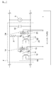
- FIG. 2 is a schematic diagram of the relay device.
- the relay device is mounted on the charger 100.
- the relay device includes a smoothing circuit 4, a voltage sensor 5, and a controller 40 included in the charger 100.
- the smoothing circuit 4 includes a first relay unit 10, a second relay unit 20, a discharge resistor 31, and a capacitor 32.
- the capacitor 32 is a smoothing capacitor.
- the first relay unit 10 includes a relay contact 11, an exciting coil 12, a temperature sensor 13, and a heater 14.
- the relay contact 11, the exciting coil 12, the temperature sensor 13, and the heater 14 are accommodated in a case.
- the relay contact 11 is a contact (a contact) that is in a closed state (on state) when the excitation coil 12 is energized.
- the relay contact 11 is always open and is closed by energizing the exciting coil 12.
- the relay contact 11 is a normally open contact.
- the relay contact 11 is connected in series with the discharge resistor 31.
- the excitation coil 12 generates a magnetic field and mechanically moves the relay contact 11 to switch the relay switch on and off.
- the exciting coil 12 is provided in the vicinity of the relay contact 11.
- the relay contact 11 and the exciting coil 12 function as a first relay switch.
- the temperature sensor 13 is a sensor that detects the temperature of the relay contact 11.
- the heater 14 is provided in the vicinity of the relay contact 11 and warms the relay contact 11.
- the second relay unit 20 has a relay contact 21, an exciting coil 22, a temperature sensor 23, and a heater 24.
- the relay contact 21, the exciting coil 22, the temperature sensor 23, and the heater 24 are accommodated in a case.
- the relay contact 21 is a contact (b contact) that is in an open state (off state) when the excitation coil 22 is energized.
- the relay contact 21 is a normally closed contact.
- the relay contact 21 is in an open state by energizing the exciting coil 22.
- the relay contact 21 is connected in series with the discharge resistor 31.
- the relay contact 11 and the relay contact 21 are connected in parallel.
- the excitation coil 22 generates a magnetic field and mechanically moves the relay contact 21 to switch the relay switch on and off.
- the exciting coil 22 is provided in the vicinity of the relay contact 21.
- the relay contact 21 and the exciting coil 22 function as a second relay switch.
- the temperature sensor 23 is a sensor that detects the temperature of the relay contact 21.
- the heater 24 is provided in the vicinity of the relay contact 21 and warms the temperature of the relay contact 21.
- the parallel circuit formed by the relay contact 11 and the relay contact 21 is connected in series to the discharge resistor 31.
- a connection circuit between the parallel circuit of the relay contacts 11 and 21 and the discharge resistor 31 is connected to the capacitor 32 in parallel.
- the discharge resistor 31 is a resistor for discharging the electric charge charged in the capacitor 32.
- the discharge resistor 31 is connected between a pair of power supply lines (corresponding to the output line of the inverter 2).
- the controller 40 controls the first relay unit 10 and the second relay unit 20.
- the controller 40 controls the discharge circuit by switching on / off of energization to the excitation coil 12 and on / off of energization to the excitation coil 22.
- the voltage detected by the voltage sensor and the temperature detected by the temperature sensors 13 and 23 are input to the controller 40.
- the controller 40 switches the heaters 14 and 24 on and off.
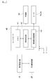
- FIG. 3 is a block diagram of the configuration controlled by the controller 40 and the controller 40.
- the first drive circuit 15 is connected to the excitation coil 12.
- the first drive circuit 15 has a switch, a power supply, and the like.
- the first drive circuit 15 drives the first relay unit 10 by conducting current to the exciting coil 12.
- the second drive circuit 25 is connected to the excitation coil 22.
- the second drive circuit 25 has a switch, a power supply, and the like.
- the second drive circuit 25 drives the second relay unit 20 by conducting current to the exciting coil 22.
- the controller 40 includes a memory 41, an abnormality determination unit 42, and a foreign matter removal control unit 43.
- the controller 40 has a CPU, a RAM and the like in addition to the memory 41.
- the controller 40 includes an abnormality determination unit 42 and a foreign matter removal control unit 43 as functional blocks of the abnormality determination function and the relay protection function.
- the abnormality determination unit 42 determines whether or not an abnormality has occurred in the first relay unit 10 and the second relay unit 20, respectively.
- the foreign matter removal control unit 43 raises the temperature of the heaters 14 and 15 and melts the ice attached to the relay contacts 11 and 21. Further, the foreign matter removal control unit 43 switches the relay switch included in the first relay unit 10 and the second relay unit 20 on and off via the first drive circuit 15 and the second drive circuit 25, so that the relay Remove foreign material adhering to the contacts.
- the freezing of the relay contacts 11 and 21 will be described.
- the water in the relay unit may become ice and the relay contacts may freeze.
- Relay units have different conditions in which icing is likely to occur depending on the internal structure or the nature of the contacts. Freezing is likely to occur when the temperature difference between the ambient temperature of the relay contact and the temperature of the relay contact (temperature of the contact portion) is large.
- the relay contact 11 is an a contact that is closed when energized.
- the charger 100 When the charger 100 is not driven, no current flows through the exciting coil 12, and the relay contact 11 is in an open state. Therefore, when the charger 1 is driven, the temperature difference between the ambient temperature of the relay contact 11 and the temperature of the relay contact is small.
- the relay contact 21 is a b contact that is opened when energized.
- the state where the current flows through the exciting coil 22 is maintained, and the relay contact 21 is opened. Since the temperature of the exciting coil 22 is increased by energization of the exciting coil 22, the ambient temperature of the relay contact 21 becomes higher than the temperature of the relay contact 21. Due to the temperature difference between the ambient temperature of the relay contact 21 and the temperature of the relay contact 21, the surface temperature of the relay contact is condensed, and the condensed moisture becomes an ice film. Such freezing causes poor contact of the relay.
- the controller 40 causes a current to flow through the exciting coil 22 and the relay contact 21 is opened. Since the current flows through the exciting coil 22 in the process in which the temperature around the relay contact 21 and the relay contact 21 decreases after the relay contact 21 is opened, the contact temperature of the relay contact 21 is It becomes lower than the ambient temperature, and the temperature difference widens. As a result, icing occurs at the relay contacts, causing poor relay contact.
- the relay contact 11 is connected in parallel to the relay contact 21.
- the contact failure of the relay contact 21 occurs due to freezing of the relay contact 21
- the charge of the capacitor 32 can be discharged using the relay contact 11.
- a relay apparatus can be normally operate
- FIG. 4 is a flowchart showing a control flow of the controller 40.
- the control flow shown in FIG. 4 is executed when the capacitor 32 is discharged after being charged by the charger 100.
- the controller 40 executes the control flow shown in FIG. 4 at every timing when charging is completed.
- step 1 the abnormality determination unit 42 increments the number of times of charging N.
- the incremented number N of times of charging is stored in the memory 41 for use in determining an abnormality after the next charging.
- step 2 the abnormality determination unit 42 determines whether N is an even number.
- the abnormality determination unit 42 turns on the relay contact (first relay) 11 and turns off the relay contact (second relay) 21 in step 3. On the other hand, if N is an odd number, the abnormality determination unit 42 turns off the relay contact 11 and turns on the relay contact 21 in step 4.
- the abnormality determination unit 42 determines whether or not a discharge abnormality has occurred. Specifically, the abnormality determination unit 42 detects the output voltage of the capacitor 32 using the voltage sensor 5 with either one of the relay contact 11 and the relay contact 21 turned on. The abnormality determination unit 42 determines whether or not the output voltage of the capacitor 32 is higher than the threshold voltage.
- the threshold voltage is a threshold for detecting a discharge abnormality. When the output voltage of the capacitor 32 is higher than the threshold voltage, the abnormality determination unit 42 determines that a discharge abnormality has occurred due to an abnormality of the relay switch in the on state. On the other hand, when the output voltage of the capacitor 32 is equal to or lower than the threshold voltage, the abnormality determination unit 42 determines that the relay in the on state is normal and is normally discharged.
- the abnormality determination unit 42 determines that there is a discharge abnormality.
- the controller 40 ends the control flow. If it is determined that the battery is normally discharged, the controller 40 ends the control flow. If it is determined that the discharge is abnormal, the abnormality determination unit 42 increments the number of abnormalities ( N_r1 or N_r2 ) of the relay that is turned on in step 6. The number of abnormalities ( N_r1 or N_r2 ) indicates the number of times that the abnormality determining unit 42 determines that a discharge abnormality has occurred. N_r1 indicates the number of abnormalities of the relay contact 11, and N_r2 indicates the number of abnormalities of the relay contact 21.
- the abnormality determination unit 42 The number of abnormalities ( N_r2 ) is incremented.
- step 7 the abnormality determination unit 42 determines whether or not the number of abnormalities ( N_r1 ) or the number of abnormalities ( N_r2 ) is 2 or more.
- the abnormality determination unit 42 determines whether the number of abnormalities ( N_r1 ) or the number of abnormalities ( N_r2 ) is 2 or more. It is determined that an abnormality has occurred at the contacts 11 and 21. That is, when the abnormality determination unit 42 determines that one of the relay contacts 11 and 21 among the relay contact 11 and the relay contact 21 has a discharge abnormality twice or more in succession, It is determined that 21 abnormality has occurred. Thereby, the determination accuracy can be increased. When it is determined that an abnormality has occurred in the relay contacts 11, 21, the abnormality determination unit 42 notifies the user of the abnormality in the relay contacts 11, 21 using the alarm device 50.
- the abnormality determining unit 42 sets the relay contacts 11, 21 that have been turned on.
- the relay contacts 11 and 21 that have been turned off are turned on.
- the abnormality determination unit 42 11 is incremented ( N_r1 ).
- the number of abnormalities ( N_r1 ) is changed from 0 to 1, and the number of abnormalities ( N_r2 ) is set to 0. Since the number of abnormalities ( N_r1 , N_r2 ) is less than 2, the control flow proceeds from step 7 to step 8.
- the abnormality determination unit 42 switches the relay contact 11 from on to off, and relay contact 21 Switch from off to on.
- step 9 the abnormality determination unit 42 determines whether or not a discharge abnormality has occurred.
- the determination method for the discharge abnormality is the same as the determination method in Step 5. If it is determined that a discharge abnormality has occurred, the abnormality determination unit 42 determines in step 11 that an abnormality has occurred in the relay contacts 11, 21. If the abnormality determination unit 42 determines that there is a discharge abnormality in the control flow in step 9, it determines that there is a discharge abnormality in the control flow in step 5. That is, since it is determined that the relay contact 11 and the relay contact 21 are abnormal once each time, the abnormality determination unit 42 finally determines that the relay contact 11 or 21 is abnormal. . Thereby, safety can be improved.
- step 10 the abnormality determination unit determines whether or not the number of abnormalities ( N_r1 ) or the number of abnormalities ( N_r2 ) is 1. When the number of abnormalities ( N_r1 ) and the number of abnormalities ( N_r2 ) are not 1, the controller 40 ends the control flow. If it is determined that the discharge is abnormal, the controller 40 performs foreign matter removal control in step 20.
- FIG. 5 is a flowchart showing a control flow of foreign matter removal control.
- the foreign matter removal control unit 43 detects the temperature of the relay contacts 11 and 21 using the temperature sensors 13 and 23. In step 22, the foreign matter removal control unit 43 determines whether or not the detected temperature is lower than the temperature threshold.
- the temperature threshold is a threshold indicating a low temperature environment.
- the temperature of the low temperature environment is a temperature at which freezing is likely to occur.
- the foreign matter removal control unit 43 turns on the heaters 14 and 24 in step 22 respectively.
- the foreign matter removal control unit 43 executes the control flow of step S23.
- step 23 the foreign matter removal control unit 43 turns on the relay contact (first relay) 11 by flowing current through the exciting coil 12, and does not flow current through the exciting coil 22, but relay contact (second relay) 21. Turn off.
- step 24 the foreign matter removal control unit 43 turns on the switch included in the first drive circuit 15, measures the elapsed time from the time when the current is passed through the exciting coil 12, and the elapsed time reaches 300 ms. It is determined whether or not. Actually, since there is a delay time until the current flows through the exciting coil 12, a standby time (300 ms) is provided. If 300 ms has elapsed, the control flow proceeds to step 25. Note that the standby time is not necessarily set to 300 ms.
- step 25 the foreign matter removal control unit 43 stops energizing the exciting coil 12 and turns off the relay contact 11. Further, the foreign matter removal control unit 43 turns on the relay contact 21 by causing a current to flow through the exciting coil 22.
- step 26 the foreign matter removal control unit 43 turns on the switch included in the second drive circuit 25, measures the elapsed time from the time when the current is passed through the exciting coil 22, and the elapsed time reaches 300 ms. It is determined whether or not. If 300 ms has elapsed, the control flow proceeds to step 27.
- step 27 the foreign matter removal control unit 43 determines whether or not the number of wiping operations is equal to or greater than a predetermined threshold value.
- the number of wiping times indicates the number of times the relay contacts 11 and 21 are switched on and off, and the cycle from step 23 to step 25 is one.
- the threshold value represents the end timing of wiping by the number of times.
- the threshold is set, for example, twice. Wiping is an operation in which the relay contacts 11 and 21 are repeatedly mechanically switched on and off.
- the foreign matter removal control unit 43 increments the number of wiping and then executes the control flow of step 23. If the number of wiping times is equal to or greater than the predetermined threshold, the foreign matter removal control unit 43 ends the foreign matter removal control flow. The controller 40 ends the control flow.
- the present embodiment includes the capacitor 32 included in the charger 100 and the discharge circuit that discharges the electric charge charged in the capacitor 32.
- the discharge circuit is connected to the discharge resistor 31, the first relay switch having the relay contact 11 that is closed when energized, and connected in parallel to the first relay switch, and is opened when energized.
- a second relay switch having a relay contact 21.
- the relay switch provided in the charger 100 employs a b-contact to electrically connect the discharge resistor 31 and the capacitor 32 when a power failure occurs during charging. Since the b contact is turned on when no current flows to the exciting coil, the discharge resistor 31 and the capacitor 32 can be conducted even when a power failure occurs during charging.
- the relay switch having the b contact when the charger 100 is not driven, it is necessary to pass a current through the exciting coil in order to disconnect the discharge resistor 31 and the capacitor 32.
- a current must be passed through the exciting coil in order to keep the discharge resistor 31 and the capacitor 32 disconnected during battery charging.
- the contact temperature of the b contact becomes lower than the ambient temperature of the contact, and the temperature difference is widened. Therefore, freezing occurs at the b contact.
- the relay contact 11 that is the a contact is connected in parallel to the relay contact 21 that is the b contact.
- the a contact is a switch that is less likely to freeze than the b contact. Therefore, even when icing occurs at the b contact, the a contact can be used for discharging. As a result, the relay device can be operated normally even under conditions where icing is likely to occur while ensuring safety when a power failure occurs during charging.
- the first relay switch is turned on and the second relay switch is turned off, and the first relay switch is turned off and the second relay switch is turned on.
- the abnormality of the switch and the second relay switch is determined.
- two types of relay switches are mutually used during the discharge operation to determine an abnormality of the two types of relay switches.
- the abnormality determination unit 42 when the number of times of charging is an even number, the relay contact 11 is turned on and the relay contact 21 is turned off to determine the abnormality of the relay switch.
- the relay contact 11 When the number of times of charging is an odd number, the relay contact 11 is turned off and the relay contact 21 is turned on to determine whether the relay switch is abnormal. Therefore, when an abnormality occurs in one of the relay contacts 11 and 21, the relay contact where the abnormality has occurred can be specified. Therefore, the relay device according to the present embodiment can improve the safety of the relay.
- the number of times of abnormality determination is calculated, and when the number of times of abnormality determination is two or more, the relay switch abnormality is notified. Thereby, abnormality determination accuracy can be improved.
- the charge of the capacitor 32 cannot be discharged. With the switch on and one relay switch off, the charge is discharged. Thereby, when one of the relay switches is not closed due to freezing or the like, the charge of the capacitor 32 can be discharged using the other relay switch.
- the foreign matter removal control for removing the foreign matter at the contact point is performed. Execute for relay switch. Thereby, the foreign material adhering to the contact of one relay switch can be removed.
- the abnormality determination by the abnormality determination unit 42 may be performed after the charger 100 is driven and before the start of charging.
- the foreign matter removal control by the foreign matter removal control unit 43 may be executed after the vehicle battery is charged and before the next charging.
- the first relay switch and the second relay switch are switched to each other to determine whether the first relay switch and the second relay switch are abnormal.
- the abnormality of the first relay switch is determined during the first half of the predetermined discharge time after the end of charging, and the abnormality of the second relay switch is determined during the second half of the time.
- the abnormality determination unit 42 determines the abnormality of the first relay switch, the abnormality determination unit 42 turns on the first relay switch and turns off the second relay switch, and the first relay switch based on the detection voltage of the voltage sensor 5. Judge abnormalities.
- the abnormality determination unit 42 turns on the first relay switch based on the detection voltage of the voltage sensor 5 with the first relay switch turned on and the second relay switch turned on. Determine whether the relay switch is abnormal.
- FIG. 6 is a flowchart showing a control flow of the controller in the relay device.
- the timing for executing the foreign substance removal control is different from that in the first embodiment.
- the contents and configuration of the control flow other than this are the same as those in the first embodiment described above, and the description thereof is incorporated.
- the abnormality determination unit 42 executes the control flow shown in FIG.
- the control flow of steps 31 to 35 is the same as that of steps 1 to 5 executed by the abnormality determination unit 42 according to the first embodiment.
- step 36 the foreign matter removal control unit 43 executes foreign matter removal control.
- the foreign matter removal control is the same as the foreign matter removal control in the first embodiment.
- step 37 the abnormality determination unit 42 turns on the relay contacts 11 and 21 that have been turned on immediately before the foreign matter removal control, and again turns on the relay contacts 11 and 21 that have been turned off immediately before the foreign matter removal control. Turn off.
- the abnormality determination unit 42 detects the output voltage of the capacitor 32 using the voltage sensor 5 and compares the detected voltage with the threshold voltage.
- the abnormality determination unit 42 determines whether or not a discharge abnormality has occurred based on the comparison result.
- the foreign matter determination method is the same as in step 35.
- step 36 when the relay contact 11 is turned off and the relay contact 21 is turned on in the control flow of step 34 and it is determined in the control flow of step 35 that there is a discharge abnormality, foreign matter removal control is executed in step 36. Later, the abnormality determination unit 42 turns off the relay contact 11 and turns on the relay contact 21 to determine whether or not the discharge is normally performed.
- step 37 If it is determined that the battery is normally discharged, the controller 40 ends the control flow. If it is determined that the discharge is abnormal, the control flow proceeds from step 37 to step 38.
- Step 38 to Step 43 The control flow from Step 38 to Step 43 is the same as that from Step 6 to Step 11 executed by the abnormality determination unit 42 according to the first embodiment.
Abstract
Provided is a relay device comprising: a capacitor 32 included in a charger 100, and a discharge circuit which discharges an electric charge charged in the capacitor 32. The discharge circuit has: a discharge resistor 31; a first relay switch connected to the discharge resistor 31, and having a contact that becomes a closed state through the passage of electric current to an excitation coil; and a second relay switch connected in parallel to the first relay switch, and having a contact that opens via the passage of electric current to an excitation coil.
Description
本発明は、リレー装置に関するものである。
The present invention relates to a relay device.
従来より、リレー接点間に導通異常が発生している場合には、当該リレー接点間に所定の電位差を持たせた状態で電源リレー回路を開閉することで、リレー接点間に存在する氷の皮膜を除去する電源リレー制御装置が開示されている(特許文献1)。
Conventionally, when a continuity abnormality occurs between relay contacts, the ice film that exists between the relay contacts is opened and closed by opening and closing the power relay circuit with a predetermined potential difference between the relay contacts. A power supply relay control device that eliminates the problem is disclosed (Patent Document 1).
しかしながら、氷の皮膜を除去できない場合には、リレー装置が正常に動作できないという問題があった。
However, when the ice film cannot be removed, there is a problem that the relay device cannot operate normally.
本発明が解決しようとする課題は、氷結が発生しやすい環境下で、正常に動作可能なリレー装置を提供することである。
The problem to be solved by the present invention is to provide a relay device that can operate normally in an environment where freezing is likely to occur.
本発明は、コンデンサに充電された電荷を放電する放電抵抗と、第1リレースイッチと第2リレースイッチとを並列に接続した並列回路とを備え、当該並列回路を当該放電抵抗に接続し、第1リレースイッチの接点を、通電により通常開になる接点とし、第2リレースイッチの接点を、通電により通常閉になる接点とすることによって上記課題を解決する。
The present invention includes a discharge resistor that discharges a charge charged in a capacitor, and a parallel circuit in which a first relay switch and a second relay switch are connected in parallel, the parallel circuit is connected to the discharge resistor, The above-mentioned problem is solved by making the contact of one relay switch a contact that normally opens when energized and the contact of the second relay switch that normally closes when energized.
本発明は、氷結が発生しやすい条件下で、リレー装置を正常に動作させることができる。
The present invention can operate the relay device normally under conditions where icing is likely to occur.
以下、本発明の実施形態を図面に基づいて説明する。
Hereinafter, embodiments of the present invention will be described with reference to the drawings.
《第1実施形態》
図1は、本実施形態に係るリレー装置を含む充電器及び車両の概略図である。充電器100は、車両用の充電装置である。充電器100は充電ケーブルを介して車両200に接続される。充電器100は、駐車場等、安定した電源を確保できる場所に設置されている。 << First Embodiment >>
FIG. 1 is a schematic diagram of a charger and a vehicle including a relay device according to the present embodiment. Thecharger 100 is a vehicle charging device. The charger 100 is connected to the vehicle 200 via a charging cable. The charger 100 is installed in a place such as a parking lot where a stable power source can be secured.
図1は、本実施形態に係るリレー装置を含む充電器及び車両の概略図である。充電器100は、車両用の充電装置である。充電器100は充電ケーブルを介して車両200に接続される。充電器100は、駐車場等、安定した電源を確保できる場所に設置されている。 << First Embodiment >>
FIG. 1 is a schematic diagram of a charger and a vehicle including a relay device according to the present embodiment. The
車両200は、電気自動車又はハイブリッド自動車など、バッテリを有する電動車両である。
Vehicle 200 is an electric vehicle having a battery, such as an electric vehicle or a hybrid vehicle.
図1に示すように、充電器100は、交流電源1、インバータ2、整流回路3、平滑回路4、電圧センサ5、及びコネクタ6を有している。交流電源1は、例えば三相200Vの交流電力を出力する。インバータ(INV)2は、交流電源から入力される交流を直流に変換する回路である。インバータ2は、交流電源1と整流回路3の間に接続されている。
As shown in FIG. 1, the charger 100 includes an AC power source 1, an inverter 2, a rectifier circuit 3, a smoothing circuit 4, a voltage sensor 5, and a connector 6. The AC power source 1 outputs, for example, three-phase 200V AC power. The inverter (INV) 2 is a circuit that converts alternating current input from an alternating current power source into direct current. The inverter 2 is connected between the AC power source 1 and the rectifier circuit 3.
整流回路3は、インバータ2から出力される出力電流を整流する。整流回路3はインバータ2の出力側に接続されている。平滑回路4は、整流回路で整流された出力電力の波形を平滑する。平滑回路4は、少なくとも平滑用のコンデンサを有している。充電器100は、平滑用のコンデンサが充電された状態で、車両用のバッテリを充電する。
The rectifier circuit 3 rectifies the output current output from the inverter 2. The rectifier circuit 3 is connected to the output side of the inverter 2. The smoothing circuit 4 smoothes the waveform of the output power rectified by the rectifier circuit. The smoothing circuit 4 has at least a smoothing capacitor. The charger 100 charges the vehicle battery while the smoothing capacitor is charged.
電圧センサ5は、平滑回路4のコンデンサに対して並列に接続されている。電圧センサ5は、コンデンサの電圧を検出することで、充電器100の出力電圧を検出する。
The voltage sensor 5 is connected in parallel with the capacitor of the smoothing circuit 4. The voltage sensor 5 detects the output voltage of the charger 100 by detecting the voltage of the capacitor.
コネクタ6は、車両の充電口に接続される器具であり、充電ケーブルの先端部分に設けられている。
The connector 6 is an instrument connected to the charging port of the vehicle, and is provided at the tip of the charging cable.
車両200は、バッテリ210及び車両用リレー220を備えている。バッテリ210は、リチウムイオン電池又はニッケル水素電池等の二次電池を複数接続することで構成されている。バッテリ210は、車両の電力源となる。車両用リレー220は、バッテリ210と充電口(コネクタ6の接続先に相当)との間の電気的な導通及び遮断を切り換えるためのリレースイッチである。なお、図1では、車両200の構成要素のうち、外部充電に関する構成要素の一部を図示している。車両200は、バッテリ210及び車両用リレー220に限らず、モータ等の他の構成要素を備えている。
The vehicle 200 includes a battery 210 and a vehicle relay 220. The battery 210 is configured by connecting a plurality of secondary batteries such as lithium ion batteries or nickel metal hydride batteries. The battery 210 is a power source for the vehicle. The vehicle relay 220 is a relay switch for switching between electrical connection and disconnection between the battery 210 and a charging port (corresponding to a connection destination of the connector 6). In FIG. 1, some of the components related to external charging among the components of the vehicle 200 are illustrated. The vehicle 200 includes not only the battery 210 and the vehicle relay 220 but also other components such as a motor.
次に、図2を用いて、本実施形態に係るリレー装置を説明する。図2は、リレー装置の概略図である。リレー装置は、充電器100に搭載されている。リレー装置は、充電器100に含まれる平滑回路4、電圧センサ5、及びコントローラ40を備えている。
Next, the relay device according to the present embodiment will be described with reference to FIG. FIG. 2 is a schematic diagram of the relay device. The relay device is mounted on the charger 100. The relay device includes a smoothing circuit 4, a voltage sensor 5, and a controller 40 included in the charger 100.
平滑回路4は、第1リレーユニット10、第2リレーユニット20、放電抵抗31、及びコンデンサ32を有している。コンデンサ32が平滑用のコンデンサである。
The smoothing circuit 4 includes a first relay unit 10, a second relay unit 20, a discharge resistor 31, and a capacitor 32. The capacitor 32 is a smoothing capacitor.
第1リレーユニット10は、リレー接点11、励磁コイル12、温度センサ13、及びヒータ14を有している。リレー接点11、励磁コイル12、温度センサ13、及びヒータ14はケースに収容されている。
The first relay unit 10 includes a relay contact 11, an exciting coil 12, a temperature sensor 13, and a heater 14. The relay contact 11, the exciting coil 12, the temperature sensor 13, and the heater 14 are accommodated in a case.
リレー接点11は、励磁コイル12への通電によりクローズ状態(オン状態)となる接点(a接点)である。リレー接点11は、常時開いており、励磁コイル12への通電により閉じた状態になる。リレー接点11はノーマリオープンの接点である。リレー接点11は、放電抵抗31に対して直列に接続されている。
The relay contact 11 is a contact (a contact) that is in a closed state (on state) when the excitation coil 12 is energized. The relay contact 11 is always open and is closed by energizing the exciting coil 12. The relay contact 11 is a normally open contact. The relay contact 11 is connected in series with the discharge resistor 31.
励磁コイル12は、磁場を発生させて、リレー接点11を機械的に動かすことで、リレースイッチのオン、オフを切り換える。励磁コイル12はリレー接点11の付近に設けられている。リレー接点11及び励磁コイル12が、第1リレースイッチとして機能する。温度センサ13は、リレー接点11の温度を検出センサである。ヒータ14は、リレー接点11の付近に設けられており、リレー接点11を暖める。
The excitation coil 12 generates a magnetic field and mechanically moves the relay contact 11 to switch the relay switch on and off. The exciting coil 12 is provided in the vicinity of the relay contact 11. The relay contact 11 and the exciting coil 12 function as a first relay switch. The temperature sensor 13 is a sensor that detects the temperature of the relay contact 11. The heater 14 is provided in the vicinity of the relay contact 11 and warms the relay contact 11.
第2リレーユニット20は、リレー接点21、励磁コイル22、温度センサ23、及びヒータ24を有している。リレー接点21、励磁コイル22、温度センサ23、及びヒータ24はケースに収容されている。
The second relay unit 20 has a relay contact 21, an exciting coil 22, a temperature sensor 23, and a heater 24. The relay contact 21, the exciting coil 22, the temperature sensor 23, and the heater 24 are accommodated in a case.
リレー接点21は、励磁コイル22への通電によりオープン状態(オフ状態)となる接点(b接点)である。リレー接点21は、ノーマリクローズの接点である。充電装置1が駆動していない場合、及び、充電装置1が車両用のバッテリ210を充電している場合には、リレー接点21は、励磁コイル22への通電により開いた状態になっている。リレー接点21は、放電抵抗31に対して直列に接続されている。またリレー接点11及びリレー接点21は並列に接続されている。
The relay contact 21 is a contact (b contact) that is in an open state (off state) when the excitation coil 22 is energized. The relay contact 21 is a normally closed contact. When the charging device 1 is not driven and when the charging device 1 is charging the vehicle battery 210, the relay contact 21 is in an open state by energizing the exciting coil 22. The relay contact 21 is connected in series with the discharge resistor 31. The relay contact 11 and the relay contact 21 are connected in parallel.
励磁コイル22は、磁場を発生させて、リレー接点21を機械的に動かすことで、リレースイッチのオン、オフを切り換える。励磁コイル22はリレー接点21の付近に設けられている。リレー接点21及び励磁コイル22が、第2リレースイッチとして機能する。温度センサ23は、リレー接点21の温度を検出センサである。ヒータ24は、リレー接点21の付近に設けられており、リレー接点21の温度を暖める。
The excitation coil 22 generates a magnetic field and mechanically moves the relay contact 21 to switch the relay switch on and off. The exciting coil 22 is provided in the vicinity of the relay contact 21. The relay contact 21 and the exciting coil 22 function as a second relay switch. The temperature sensor 23 is a sensor that detects the temperature of the relay contact 21. The heater 24 is provided in the vicinity of the relay contact 21 and warms the temperature of the relay contact 21.
リレー接点11とリレー接点21で形成される並列回路は、放電抵抗31に直列に接続されている。そして、リレー接点11、21の並列回路と放電抵抗31との接続回路がコンデンサ32に対して、並列に接続されている。リレー接点11とリレー接点21の少なくともいずれか一方のリレーがクローズ状態になると、放電抵抗31とコンデンサ32の間が導通し、コンデンサ32に充電された電荷が放電される。すなわち、第1リレーユニット10、第2リレーユニット20及び放電抵抗31で形成される回路が、コンデンサ32の電荷を放電する放電回路に相当する。
The parallel circuit formed by the relay contact 11 and the relay contact 21 is connected in series to the discharge resistor 31. A connection circuit between the parallel circuit of the relay contacts 11 and 21 and the discharge resistor 31 is connected to the capacitor 32 in parallel. When at least one of the relay contact 11 and the relay contact 21 is in a closed state, the discharge resistor 31 and the capacitor 32 are conducted, and the charge charged in the capacitor 32 is discharged. That is, the circuit formed by the first relay unit 10, the second relay unit 20, and the discharge resistor 31 corresponds to a discharge circuit that discharges the electric charge of the capacitor 32.
放電抵抗31は、コンデンサ32に充電された電荷を放電するための抵抗である。放電抵抗31は、一対の電源線(インバータ2の出力線に相当)の間に接続されている。
The discharge resistor 31 is a resistor for discharging the electric charge charged in the capacitor 32. The discharge resistor 31 is connected between a pair of power supply lines (corresponding to the output line of the inverter 2).
コントローラ40は、第1リレーユニット10及び第2リレーユニット20を制御する。コントローラ40は、励磁コイル12への通電のオン、オフ及び励磁コイル22への通電のオン、オフを切り換えることで、放電回路を制御する。電圧センサの検出電圧、及び温度センサ13、23の検出温度は、コントローラ40に入力される。また、コントローラ40は、ヒータ14,24のオン、オフを切り換える。
The controller 40 controls the first relay unit 10 and the second relay unit 20. The controller 40 controls the discharge circuit by switching on / off of energization to the excitation coil 12 and on / off of energization to the excitation coil 22. The voltage detected by the voltage sensor and the temperature detected by the temperature sensors 13 and 23 are input to the controller 40. The controller 40 switches the heaters 14 and 24 on and off.
次に、図3を用いて、コントローラ40の構成を説明する。図3は、コントローラ40により制御される構成とコントローラ40のブロック図である。
Next, the configuration of the controller 40 will be described with reference to FIG. FIG. 3 is a block diagram of the configuration controlled by the controller 40 and the controller 40.
第1駆動回路15は、励磁コイル12に接続されている。第1駆動回路15はスイッチ、電源等を有している。第1駆動回路15は、励磁コイル12に対して電流を導通させることで、第1リレーユニット10を駆動させる。
The first drive circuit 15 is connected to the excitation coil 12. The first drive circuit 15 has a switch, a power supply, and the like. The first drive circuit 15 drives the first relay unit 10 by conducting current to the exciting coil 12.
第2駆動回路25は、励磁コイル22に接続されている。第2駆動回路25はスイッチ、電源等を有している。第2駆動回路25は、励磁コイル22に対して電流を導通させることで、第2リレーユニット20を駆動させる。
The second drive circuit 25 is connected to the excitation coil 22. The second drive circuit 25 has a switch, a power supply, and the like. The second drive circuit 25 drives the second relay unit 20 by conducting current to the exciting coil 22.
コントローラ40は、メモリ41、異常判定部42及び異物除去制御部43を有している。コントローラ40は、メモリ41の他に、CPU、RAM等を有している。また、コントローラ40は、異常判定機能及びリレー保護機能の機能ブロックとして、異常判定部42及び異物除去制御部43を有している。異常判定部42は、第1リレーユニット10及び第2リレーユニット20に異常が発生しているか否か、それぞれ判定する。異物除去制御部43は、ヒータ14、15の温度を上げて、リレー接点11、21に付着した氷を溶解する。また、異物除去制御部43は、第1駆動回路15及び第2駆動回路25を介して、第1リレーユニット10及び第2リレーユニット20に含まれるリレースイッチのオン、オフを切り替えることで、リレー接点に付着した異物を除去する。
The controller 40 includes a memory 41, an abnormality determination unit 42, and a foreign matter removal control unit 43. The controller 40 has a CPU, a RAM and the like in addition to the memory 41. The controller 40 includes an abnormality determination unit 42 and a foreign matter removal control unit 43 as functional blocks of the abnormality determination function and the relay protection function. The abnormality determination unit 42 determines whether or not an abnormality has occurred in the first relay unit 10 and the second relay unit 20, respectively. The foreign matter removal control unit 43 raises the temperature of the heaters 14 and 15 and melts the ice attached to the relay contacts 11 and 21. Further, the foreign matter removal control unit 43 switches the relay switch included in the first relay unit 10 and the second relay unit 20 on and off via the first drive circuit 15 and the second drive circuit 25, so that the relay Remove foreign material adhering to the contacts.
ここで、リレー接点11、21の氷結について説明する。充電器100が低温環境下にある場合には、リレーユニットの水分が氷になって、リレー接点が凍結するおそれがある。リレーユニットは、内部構造又は接点の性質等により、氷結の発生し易い状況が異なる。リレー接点の周囲温度とリレー接点の温度(接点部分の温度)との温度差が大きい場合に、氷結が発生し易い。
Here, the freezing of the relay contacts 11 and 21 will be described. When the charger 100 is in a low temperature environment, the water in the relay unit may become ice and the relay contacts may freeze. Relay units have different conditions in which icing is likely to occur depending on the internal structure or the nature of the contacts. Freezing is likely to occur when the temperature difference between the ambient temperature of the relay contact and the temperature of the relay contact (temperature of the contact portion) is large.
本実施形態に係るリレー装置において、リレー接点11は、通電によりクローズ状態になるa接点である。充電器100が駆動しない場合には、電流は励磁コイル12に流れておらず、リレー接点11はオープン状態となる。そのため、充電器1の駆動時に、リレー接点11の周囲温度とリレー接点の温度の温度差は小さい。
In the relay device according to the present embodiment, the relay contact 11 is an a contact that is closed when energized. When the charger 100 is not driven, no current flows through the exciting coil 12, and the relay contact 11 is in an open state. Therefore, when the charger 1 is driven, the temperature difference between the ambient temperature of the relay contact 11 and the temperature of the relay contact is small.
一方、リレー接点21は、通電によりオープン状態になるb接点である。充電器100が駆動しない場合には、電流が励磁コイル22に流れている状態が維持されて、リレー接点21はオープン状態となる。励磁コイル22の通電により励磁コイル22の温度が高くなるため、リレー接点21の周囲温度がリレー接点21の温度より高くなる。リレー接点21の周囲温度とリレー接点21の温度の温度差によって、リレー接点の表面温度が結露し、結露した水分が氷の膜となる。そして、このような氷結はリレーの接触不良を引き起こす。
On the other hand, the relay contact 21 is a b contact that is opened when energized. When the charger 100 is not driven, the state where the current flows through the exciting coil 22 is maintained, and the relay contact 21 is opened. Since the temperature of the exciting coil 22 is increased by energization of the exciting coil 22, the ambient temperature of the relay contact 21 becomes higher than the temperature of the relay contact 21. Due to the temperature difference between the ambient temperature of the relay contact 21 and the temperature of the relay contact 21, the surface temperature of the relay contact is condensed, and the condensed moisture becomes an ice film. Such freezing causes poor contact of the relay.
また、充電器100の充電が終了し、コンデンサ32の電荷の放電が終了したときに、コントローラ40は、励磁コイル22に電流を流して、リレー接点21がオープン状態になる。リレー接点21がオープン状態になった後、リレー接点21及びリレー接点21の周囲の温度が低下する過程において、電流が励磁コイル22に流れているため、リレー接点21の接点温度がリレー接点21の周囲温度よりも低くなり、温度差が広がる。そのため、氷結がリレー接点で発生し、リレーの接触不良を引き起こす。
Further, when the charging of the charger 100 is completed and the discharging of the charge of the capacitor 32 is completed, the controller 40 causes a current to flow through the exciting coil 22 and the relay contact 21 is opened. Since the current flows through the exciting coil 22 in the process in which the temperature around the relay contact 21 and the relay contact 21 decreases after the relay contact 21 is opened, the contact temperature of the relay contact 21 is It becomes lower than the ambient temperature, and the temperature difference widens. As a result, icing occurs at the relay contacts, causing poor relay contact.
本実施形態では、リレー接点21で氷結が発生し易いため、リレー接点21に対して並列にリレー接点11を接続する。本実施形態では、リレー接点21の氷結によりリレー接点21の接触不良が発生した場合に、リレー接点11を用いて、コンデンサ32の電荷を放電できる。これにより、本実施形態では、氷結が発生し易い条件下で、リレー装置を正常に動作できる。
In this embodiment, since the icing is likely to occur at the relay contact 21, the relay contact 11 is connected in parallel to the relay contact 21. In the present embodiment, when the contact failure of the relay contact 21 occurs due to freezing of the relay contact 21, the charge of the capacitor 32 can be discharged using the relay contact 11. Thereby, in this embodiment, a relay apparatus can be normally operate | moved on the conditions on which icing tends to generate | occur | produce.
次に、図4を用いて、異常判定部42による異常判定制御の制御フローを説明する。図4は、コントローラ40の制御フローを示すフローチャートである。図4に示す制御フローは、充電器100による充電の後、コンデンサ32の電荷を放電する際に実行される。コントローラ40は、充電終了するタイミング毎に、図4に示す制御フローを実行する。
Next, the control flow of the abnormality determination control by the abnormality determination unit 42 will be described with reference to FIG. FIG. 4 is a flowchart showing a control flow of the controller 40. The control flow shown in FIG. 4 is executed when the capacitor 32 is discharged after being charged by the charger 100. The controller 40 executes the control flow shown in FIG. 4 at every timing when charging is completed.
ステップ1にて、異常判定部42は、充電回数Nをインクリメントする。インクリメントされた充電回数Nは、次回の充電後の異常判定の際に用いるため、メモリ41に記憶される。ステップ2にて、異常判定部42は、Nが偶数であるか否かを判定する。
In step 1, the abnormality determination unit 42 increments the number of times of charging N. The incremented number N of times of charging is stored in the memory 41 for use in determining an abnormality after the next charging. In step 2, the abnormality determination unit 42 determines whether N is an even number.
Nが偶数である場合には、ステップ3にて異常判定部42はリレー接点(第1リレー)11をオンにし、リレー接点(第2リレー)21をオフにする。一方、Nが奇数である場合には、ステップ4にて異常判定部42はリレー接点11をオフにし、リレー接点21をオンにする。
If N is an even number, the abnormality determination unit 42 turns on the relay contact (first relay) 11 and turns off the relay contact (second relay) 21 in step 3. On the other hand, if N is an odd number, the abnormality determination unit 42 turns off the relay contact 11 and turns on the relay contact 21 in step 4.
ステップ5にて、異常判定部42は放電異常が発生しているか否かを判定する。具体的には、異常判定部42は、リレー接点11及びリレー接点21のいずれか一方をオンにしている状態で、電圧センサ5を用いて、コンデンサ32の出力電圧を検出する。異常判定部42は、コンデンサ32の出力電圧が閾値電圧より高いか否かを判定する。閾値電圧は、放電異常を検出するための閾値である。コンデンサ32の出力電圧が閾値電圧より高い場合には、異常判定部42は、オン状態のリレースイッチの異常により、放電異常が発生していると判定する。一方、コンデンサ32の出力電圧が閾値電圧以下である場合には、異常判定部42は、オン状態のリレーが正常であり、正常に放電されていると判定する。
In step 5, the abnormality determination unit 42 determines whether or not a discharge abnormality has occurred. Specifically, the abnormality determination unit 42 detects the output voltage of the capacitor 32 using the voltage sensor 5 with either one of the relay contact 11 and the relay contact 21 turned on. The abnormality determination unit 42 determines whether or not the output voltage of the capacitor 32 is higher than the threshold voltage. The threshold voltage is a threshold for detecting a discharge abnormality. When the output voltage of the capacitor 32 is higher than the threshold voltage, the abnormality determination unit 42 determines that a discharge abnormality has occurred due to an abnormality of the relay switch in the on state. On the other hand, when the output voltage of the capacitor 32 is equal to or lower than the threshold voltage, the abnormality determination unit 42 determines that the relay in the on state is normal and is normally discharged.
例えばステップ3の制御フローの後、コンデンサ32のコンデンサの出力電圧が閾値電圧より高い場合には、コンデンサ32は、リレー接点11を介して放電抵抗31と電気的に導通していないため、コンデンサ32の電荷は放電されない。そのため、異常判定部42は、放電異常であると判定する。
For example, if the output voltage of the capacitor 32 is higher than the threshold voltage after the control flow in step 3, the capacitor 32 is not electrically connected to the discharge resistor 31 via the relay contact 11. The charge is not discharged. Therefore, the abnormality determination unit 42 determines that there is a discharge abnormality.
正常に放電されていると判定した場合には、コントローラ40は制御フローを終了する。放電異常であると判定した場合には、ステップ6にて異常判定部42は、オンにしたリレーの異常回数(N_r1又はN_r2)をインクリメントする。異常回数(N_r1又はN_r2)は、異常判定部42により放電異常が発生していると判定された回数を示す。N_r1はリレー接点11の異常回数を示し、N_r2はリレー接点21の異常回数を示す。
If it is determined that the battery is normally discharged, the controller 40 ends the control flow. If it is determined that the discharge is abnormal, the abnormality determination unit 42 increments the number of abnormalities ( N_r1 or N_r2 ) of the relay that is turned on in step 6. The number of abnormalities ( N_r1 or N_r2 ) indicates the number of times that the abnormality determining unit 42 determines that a discharge abnormality has occurred. N_r1 indicates the number of abnormalities of the relay contact 11, and N_r2 indicates the number of abnormalities of the relay contact 21.
例えばステップ4の制御フローで、リレー接点11をオフにしてリレー接点21をオンにして、ステップ5の制御フローで放電異常であると判定した場合には、異常判定部42は、リレー接点21の異常回数(N_r2)をインクリメントする。
For example, when the relay contact 11 is turned off and the relay contact 21 is turned on in the control flow of step 4 and it is determined that there is a discharge abnormality in the control flow of step 5, the abnormality determination unit 42 The number of abnormalities ( N_r2 ) is incremented.
ステップ7にて、異常判定部42は、異常回数(N_r1)又は異常回数(N_r2)が2以上であるか否かを判定する。
In step 7, the abnormality determination unit 42 determines whether or not the number of abnormalities ( N_r1 ) or the number of abnormalities ( N_r2 ) is 2 or more.
異常回数(N_r1)又は異常回数(N_r2)が2以上である場合には、ステップ11にて、異常判定部42は、異常回数(N_r1又はN_r2)が2以上である方のリレー接点11、21で異常が発生していると判定する。すなわち、異常判定部42は、リレー接点11及びリレー接点21のうち一方のリレー接点11、21で、連続して2回以上、放電異常が発生していると判定した場合に、リレー接点11、21の異常が発生していると判定する。これにより、判定精度を高めることができる。リレー接点11、21の異常が発生していると判定された場合には、異常判定部42は警報機50を用いて、ユーザに対してリレー接点11、21の異常を通知する。
When the number of abnormalities ( N_r1 ) or the number of abnormalities ( N_r2 ) is 2 or more, in step 11, the abnormality determination unit 42 determines whether the number of abnormalities ( N_r1 or N_r2 ) is 2 or more. It is determined that an abnormality has occurred at the contacts 11 and 21. That is, when the abnormality determination unit 42 determines that one of the relay contacts 11 and 21 among the relay contact 11 and the relay contact 21 has a discharge abnormality twice or more in succession, It is determined that 21 abnormality has occurred. Thereby, the determination accuracy can be increased. When it is determined that an abnormality has occurred in the relay contacts 11, 21, the abnormality determination unit 42 notifies the user of the abnormality in the relay contacts 11, 21 using the alarm device 50.
ステップ7の判定制御で、異常回数(N_r1)及び異常回数(N_r2)が2未満である場合には、ステップ8にて、異常判定部42は、オンにしていたリレー接点11、21をオフにして、オフにしていたリレー接点11、21をオンに入れ替える。
When the number of abnormalities ( N_r1 ) and the number of abnormalities ( N_r2 ) are less than 2 in the determination control in step 7, in step 8, the abnormality determining unit 42 sets the relay contacts 11, 21 that have been turned on. The relay contacts 11 and 21 that have been turned off are turned on.
例えば、ステップ3の制御フローで、リレー接点11をオンにして、リレー接点21をオフにして、ステップ5の制御フローで放電異常であると判定した場合には、異常判定部42は、リレー接点11の異常回数(N_r1)をインクリメントする。ここでは、異常回数(N_r1)が0から1になり、異常回数(N_r2)は0とする。異常回数(N_r1、N_r2)が2未満であるため、制御フローはステップ7からステップ8に進む。ステップ3の制御フローで、リレー接点11はオンになり、リレー接点21はオフになっているため、ステップ8にて、異常判定部42は、リレー接点11をオンからオフに切り換え、リレー接点21をオフからオンに切り換える。
For example, when the relay contact 11 is turned on and the relay contact 21 is turned off in the control flow of Step 3, and it is determined that the discharge is abnormal in the control flow of Step 5, the abnormality determination unit 42 11 is incremented ( N_r1 ). Here, the number of abnormalities ( N_r1 ) is changed from 0 to 1, and the number of abnormalities ( N_r2 ) is set to 0. Since the number of abnormalities ( N_r1 , N_r2 ) is less than 2, the control flow proceeds from step 7 to step 8. In the control flow of step 3, since the relay contact 11 is turned on and the relay contact 21 is turned off, in step 8, the abnormality determination unit 42 switches the relay contact 11 from on to off, and relay contact 21 Switch from off to on.
ステップ9にて、異常判定部42は、放電異常が発生しているか否かを判定する。放電異常の判定方法は、ステップ5の判定方法と同様である。放電異常が発生していると判定された場合には、ステップ11にて異常判定部42は、リレー接点11、21で異常が発生していると判定する。異常判定部42は、ステップ9の制御フローで放電異常であると判定した場合には、ステップ5の制御フローでも放電異常であると判定している。すなわち、リレー接点11及びリレー接点21がそれぞれ1回ずつ異常であると判定されたことになるため、異常判定部42は、リレー接点11、21の異常で発生していると最終的に判定する。これにより、安全性を高めることができる。
In step 9, the abnormality determination unit 42 determines whether or not a discharge abnormality has occurred. The determination method for the discharge abnormality is the same as the determination method in Step 5. If it is determined that a discharge abnormality has occurred, the abnormality determination unit 42 determines in step 11 that an abnormality has occurred in the relay contacts 11, 21. If the abnormality determination unit 42 determines that there is a discharge abnormality in the control flow in step 9, it determines that there is a discharge abnormality in the control flow in step 5. That is, since it is determined that the relay contact 11 and the relay contact 21 are abnormal once each time, the abnormality determination unit 42 finally determines that the relay contact 11 or 21 is abnormal. . Thereby, safety can be improved.
ステップ9の制御フローで、正常に放電されていると判定した場合には、制御フローはステップ10に進む。ステップ10にて、異常判定部は、異常回数(N_r1)又は異常回数(N_r2)が1であるか否かを判定する。異常回数(N_r1)及び異常回数(N_r2)が1でない場合には、コントローラ40は制御フローを終了させる。放電異常であると判定した場合には、ステップ20にて、コントローラ40は異物除去制御を行う。
If it is determined in the control flow of step 9 that the battery is normally discharged, the control flow proceeds to step 10. In step 10, the abnormality determination unit determines whether or not the number of abnormalities ( N_r1 ) or the number of abnormalities ( N_r2 ) is 1. When the number of abnormalities ( N_r1 ) and the number of abnormalities ( N_r2 ) are not 1, the controller 40 ends the control flow. If it is determined that the discharge is abnormal, the controller 40 performs foreign matter removal control in step 20.
図5を用いて、異物除去制御の制御フローを説明する。図5は、異物除去制御の制御フローを示すフローチャートである。
The control flow of foreign matter removal control will be described with reference to FIG. FIG. 5 is a flowchart showing a control flow of foreign matter removal control.
ステップ21にて、異物除去制御部43は、温度センサ13、23を用いてリレー接点11、21の温度を検出する。ステップ22にて、異物除去制御部43は、検出温度が温度閾値未満であるか否かを判定する。温度閾値は低温環境を示す閾値である。低温環境の温度は、氷結の発生し易い温度である。
In step 21, the foreign matter removal control unit 43 detects the temperature of the relay contacts 11 and 21 using the temperature sensors 13 and 23. In step 22, the foreign matter removal control unit 43 determines whether or not the detected temperature is lower than the temperature threshold. The temperature threshold is a threshold indicating a low temperature environment. The temperature of the low temperature environment is a temperature at which freezing is likely to occur.
低温環境であると判定した場合には、ステップ22にて異物除去制御部43は、ヒータ14、24をそれぞれオンにする。リレー接点11、21の温度が温度閾値以上になると、異物除去制御部43はステップS23の制御フローを実行する。
If it is determined that the environment is a low temperature environment, the foreign matter removal control unit 43 turns on the heaters 14 and 24 in step 22 respectively. When the temperature of the relay contacts 11 and 21 is equal to or higher than the temperature threshold, the foreign matter removal control unit 43 executes the control flow of step S23.
ステップ23にて、異物除去制御部43は、励磁コイル12に電流を流すことでリレー接点(第1リレー)11をオンにし、励磁コイル22に電流を流さず、リレー接点(第2リレー)21をオフにする。ステップ24にて、異物除去制御部43は、第1駆動回路15に含まれるスイッチをオンにして、励磁コイル12に電流を流した時点からの経過時間を計測し、経過時間が300msに達したか否かを判定する。実際に、励磁コイル12に電流が流れるまでには遅延時間があるため、待機時間(300ms)を設けている。300msが経過した場合には、制御フローはステップ25に進む。なお、待機時間は、必ずしも300msにする必要はない。
In step 23, the foreign matter removal control unit 43 turns on the relay contact (first relay) 11 by flowing current through the exciting coil 12, and does not flow current through the exciting coil 22, but relay contact (second relay) 21. Turn off. In step 24, the foreign matter removal control unit 43 turns on the switch included in the first drive circuit 15, measures the elapsed time from the time when the current is passed through the exciting coil 12, and the elapsed time reaches 300 ms. It is determined whether or not. Actually, since there is a delay time until the current flows through the exciting coil 12, a standby time (300 ms) is provided. If 300 ms has elapsed, the control flow proceeds to step 25. Note that the standby time is not necessarily set to 300 ms.
ステップ25にて、異物除去制御部43は、励磁コイル12への通電を停止してリレー接点11をオフにする。また、異物除去制御部43は、励磁コイル22に電流を流すことで、リレー接点21をオンにする。ステップ26にて、異物除去制御部43は、第2駆動回路25に含まれるスイッチをオンにして、励磁コイル22に電流を流した時点からの経過時間を計測し、経過時間が300msに達したか否かを判定する。300msが経過した場合には、制御フローはステップ27に進む。
In step 25, the foreign matter removal control unit 43 stops energizing the exciting coil 12 and turns off the relay contact 11. Further, the foreign matter removal control unit 43 turns on the relay contact 21 by causing a current to flow through the exciting coil 22. In step 26, the foreign matter removal control unit 43 turns on the switch included in the second drive circuit 25, measures the elapsed time from the time when the current is passed through the exciting coil 22, and the elapsed time reaches 300 ms. It is determined whether or not. If 300 ms has elapsed, the control flow proceeds to step 27.
ステップ27にて、異物除去制御部43は、ワイピング回数が所定の閾値以上であるか否かを判定する。ワイピング回数は、リレー接点11、21のオン、オフの切り換える回数を示しており、ステップ23からステップ25までのサイクルを1回としている。閾値は、ワイピングの終了タイミングを回数で表したものである。閾値は、例えば2回に設定されている。ワイピングは、リレー接点11、21のオン、オフの機械的な切り換えを繰り返す動作である。
In step 27, the foreign matter removal control unit 43 determines whether or not the number of wiping operations is equal to or greater than a predetermined threshold value. The number of wiping times indicates the number of times the relay contacts 11 and 21 are switched on and off, and the cycle from step 23 to step 25 is one. The threshold value represents the end timing of wiping by the number of times. The threshold is set, for example, twice. Wiping is an operation in which the relay contacts 11 and 21 are repeatedly mechanically switched on and off.
ワイピング回数が所定の閾値未満である場合には、異物除去制御部43は、ワイピング回数をインクリメントした上で、ステップ23の制御フローを実行する。ワイピング回数が所定の閾値以上である場合には、異物除去制御部43は、異物除去制御フローを終了する。コントローラ40は制御フローを終了する。
When the number of wiping is less than the predetermined threshold, the foreign matter removal control unit 43 increments the number of wiping and then executes the control flow of step 23. If the number of wiping times is equal to or greater than the predetermined threshold, the foreign matter removal control unit 43 ends the foreign matter removal control flow. The controller 40 ends the control flow.
本実施形態では、ワイピングを行うことで、リレー接点11、21に付着した塵や酸化被膜等の不純物を取り除くことができる。また、リレー接点11、21が低温環境下にあり、氷結が発生し易い状態である場合には、ヒータ14、24を用いて、氷結が発生し難い接点温度まで上昇させる。これにより、リレー接点11、21に氷が付着していた場合には、氷を除去し易くなる。また、ヒータ動作とワイピング動作を組み合わせることで、異物を除去し易くなる。
In this embodiment, by wiping, impurities such as dust and oxide film adhering to the relay contacts 11 and 21 can be removed. Further, when the relay contacts 11 and 21 are in a low temperature environment and are in a state where icing is likely to occur, the heaters 14 and 24 are used to raise the contact temperature to a level where icing is unlikely to occur. Thereby, when the ice contacts the relay contacts 11 and 21, it becomes easy to remove the ice. Moreover, it becomes easy to remove foreign substances by combining the heater operation and the wiping operation.
上記のように、本実施形態では、充電器100に含まれるコンデンサ32と、コンデンサ32に充電された電荷を放電する放電回路とを備える。放電回路は、放電抵抗31と、放電抵抗31に接続され、通電によりクローズ状態となるリレー接点11をもつ第1リレースイッチと、当該第1リレースイッチに並列に接続され、通電によりオープン状態となるリレー接点21をもつ第2リレースイッチとを有する。これにより、氷結が発生しやすい条件下で、リレースイッチを正常に動作させることができる。
As described above, the present embodiment includes the capacitor 32 included in the charger 100 and the discharge circuit that discharges the electric charge charged in the capacitor 32. The discharge circuit is connected to the discharge resistor 31, the first relay switch having the relay contact 11 that is closed when energized, and connected in parallel to the first relay switch, and is opened when energized. And a second relay switch having a relay contact 21. As a result, the relay switch can be operated normally under conditions where icing is likely to occur.
ところで、充電器100に設けられるリレースイッチは、充電中に停電が発生した場合に、放電抵抗31とコンデンサ32とを電気的に導通させるために、b接点が採用される。b接点は、励磁コイルへ電流を流さない状態でオン状態になるため、充電中に停電が発生した場合でも、放電抵抗31とコンデンサ32とを導通できる。
By the way, the relay switch provided in the charger 100 employs a b-contact to electrically connect the discharge resistor 31 and the capacitor 32 when a power failure occurs during charging. Since the b contact is turned on when no current flows to the exciting coil, the discharge resistor 31 and the capacitor 32 can be conducted even when a power failure occurs during charging.
しかしながら、b接点をもつリレースイッチは、充電器100が駆動しない場合には、放電抵抗31とコンデンサ32とを切り離すために、励磁コイルに電流を流す必要がある。そして、低温環境下で、充電器100を開始した場合には、バッテリの充電中、放電抵抗31とコンデンサ32を切り離した状態を維持するために、励磁コイルに電流を流さなければならない。そして、励磁コイルへの通電によって、b接点の接点温度が接点の周囲温度よりも低くなり、温度差が広がる。そのため、氷結がb接点で発生する。
However, in the relay switch having the b contact, when the charger 100 is not driven, it is necessary to pass a current through the exciting coil in order to disconnect the discharge resistor 31 and the capacitor 32. When the charger 100 is started under a low temperature environment, a current must be passed through the exciting coil in order to keep the discharge resistor 31 and the capacitor 32 disconnected during battery charging. And by energizing the exciting coil, the contact temperature of the b contact becomes lower than the ambient temperature of the contact, and the temperature difference is widened. Therefore, freezing occurs at the b contact.
そして、氷結がb接点で発生すると、コンデンサ32の電荷を放電するために、b接点をオンにしても、放電抵抗31とコンデンサ32が接続されず、放電できない状態となる。
When freezing occurs at the b-contact, the charge of the capacitor 32 is discharged, and even if the b-contact is turned on, the discharge resistor 31 and the capacitor 32 are not connected and cannot be discharged.
本実施形態では、b接点であるリレー接点21に対して、a接点であるリレー接点11を並列に接続している。a接点は、b接点よりも、氷結が発生し難いスイッチである。そのため、氷結がb接点で発生した場合でも、a接点を用いて、放電を行うことができる。これにより、充電中に停電が発生した時の安全性を確保した上で、氷結が発生し易い条件下でも、リレー装置を正常に動作させることができる。
In this embodiment, the relay contact 11 that is the a contact is connected in parallel to the relay contact 21 that is the b contact. The a contact is a switch that is less likely to freeze than the b contact. Therefore, even when icing occurs at the b contact, the a contact can be used for discharging. As a result, the relay device can be operated normally even under conditions where icing is likely to occur while ensuring safety when a power failure occurs during charging.
また本実施形態では、第1リレースイッチをオンに第2リレースイッチをオフにした状態と、第1リレースイッチをオフに第2リレースイッチをオンにした状態とを相互に切り換えて、第1リレースイッチ及び第2リレースイッチの異常を判定する。
In the present embodiment, the first relay switch is turned on and the second relay switch is turned off, and the first relay switch is turned off and the second relay switch is turned on. The abnormality of the switch and the second relay switch is determined.
すなわち、本実施形態では、放電動作時に2種類のリレースイッチを相互に使用して、2種類のリレースイッチの異常を判定する。異常判定部42の制御フローでは、充電回数が偶数回のときに、リレー接点11をオンにリレー接点21をオフにして、リレースイッチの異常を判定する。また、充電回数が奇数回のときに、リレー接点11をオフにリレー接点21をオンにして、リレースイッチの異常を判定する。これにより、リレー接点11及びリレー接点21のうち、どちらか一方のリレー接点に異常が生じた場合には、異常が発生したリレー接点を特定できる。ゆえに、本実施形態に係るリレー装置は、リレーの安全性を向上できる。
That is, in the present embodiment, two types of relay switches are mutually used during the discharge operation to determine an abnormality of the two types of relay switches. In the control flow of the abnormality determination unit 42, when the number of times of charging is an even number, the relay contact 11 is turned on and the relay contact 21 is turned off to determine the abnormality of the relay switch. When the number of times of charging is an odd number, the relay contact 11 is turned off and the relay contact 21 is turned on to determine whether the relay switch is abnormal. Thereby, when an abnormality occurs in one of the relay contacts 11 and 21, the relay contact where the abnormality has occurred can be specified. Therefore, the relay device according to the present embodiment can improve the safety of the relay.
また本実施形態では、異常判定回数を算出し異常判定回数が2回以上である場合に、リレースイッチの異常を通知する。これにより、異常の判定精度を高めることができる。
In this embodiment, the number of times of abnormality determination is calculated, and when the number of times of abnormality determination is two or more, the relay switch abnormality is notified. Thereby, abnormality determination accuracy can be improved.
また本実施形態では、第1リレースイッチ及び第2リレースイッチのうち何れか一方のリレースイッチをオンに他方のリレースイッチをオフにした状態でコンデンサ32の電荷を放電できない場合には、他方のリレースイッチをオンに一方のリレースイッチをオフにした状態で、電荷を放電させる。これにより、一方のリレースイッチが氷結等でクローズ状態にならない場合に、他方のリレースイッチを用いて、コンデンサ32の電荷を放電できる。
In the present embodiment, when one of the first relay switch and the second relay switch is turned on and the other relay switch is turned off, the charge of the capacitor 32 cannot be discharged. With the switch on and one relay switch off, the charge is discharged. Thereby, when one of the relay switches is not closed due to freezing or the like, the charge of the capacitor 32 can be discharged using the other relay switch.
また本実施形態では、第1リレースイッチ及び第2リレースイッチのうち何れか一方のリレースイッチをオンにした状態で電荷を放電できない場合には、接点の異物を除去する異物除去制御を、一方のリレースイッチに対して実行する。これにより、一方のリレースイッチの接点に付着した異物を除去できる。
Further, in the present embodiment, when one of the first relay switch and the second relay switch is turned on and the charge cannot be discharged, the foreign matter removal control for removing the foreign matter at the contact point is performed. Execute for relay switch. Thereby, the foreign material adhering to the contact of one relay switch can be removed.
なお、本実施形態において、異常判定部42による異常判定は、充電器100の駆動後、充電開始前に実行されてもよい。また異物除去制御部43による異物除去制御は、車両用バッテリの充電後、次回の充電時までに実行してもよい。
In the present embodiment, the abnormality determination by the abnormality determination unit 42 may be performed after the charger 100 is driven and before the start of charging. The foreign matter removal control by the foreign matter removal control unit 43 may be executed after the vehicle battery is charged and before the next charging.
なお、本実施形態では、1回の充電の後に、第1リレースイッチと第2リレースイッチとを相互に切り換えて、第1リレースイッチ及び第2リレースイッチの異常を判定する。例えば、充電の終了後の所定の放電時間のうち、前半の時間に第1リレースイッチの異常を判定し、後半の時間に第2リレースイッチの異常を判定する。第1リレースイッチの異常判定の際には、異常判定部42は、第1リレースイッチをオンにし、第2リレースイッチをオフにした状態で、電圧センサ5の検出電圧に基づいて第1リレースイッチの異常を判定する。また、第2リレースイッチの異常判定の際には、異常判定部42は、第1リレースイッチをオンにし、第2リレースイッチをオンにした状態で、電圧センサ5の検出電圧に基づいて第2リレースイッチの異常を判定する。
In the present embodiment, after one charge, the first relay switch and the second relay switch are switched to each other to determine whether the first relay switch and the second relay switch are abnormal. For example, the abnormality of the first relay switch is determined during the first half of the predetermined discharge time after the end of charging, and the abnormality of the second relay switch is determined during the second half of the time. When determining the abnormality of the first relay switch, the abnormality determination unit 42 turns on the first relay switch and turns off the second relay switch, and the first relay switch based on the detection voltage of the voltage sensor 5. Judge abnormalities. Further, when determining the abnormality of the second relay switch, the abnormality determination unit 42 turns on the first relay switch based on the detection voltage of the voltage sensor 5 with the first relay switch turned on and the second relay switch turned on. Determine whether the relay switch is abnormal.
《第2実施形態》
本発明の他の実施形態に係るリレー装置を説明する。図6は、リレー装置において、コントローラの制御フローを示すフローチャートである。本実施形態では、第1実施形態に対して、異物除去制御を実行するタイミングが異なる。これ以外の制御フローの内容及び構成は上述した第1実施形態と同じであり、その記載を援用する。 << Second Embodiment >>
A relay device according to another embodiment of the present invention will be described. FIG. 6 is a flowchart showing a control flow of the controller in the relay device. In the present embodiment, the timing for executing the foreign substance removal control is different from that in the first embodiment. The contents and configuration of the control flow other than this are the same as those in the first embodiment described above, and the description thereof is incorporated.
充電器100による充電の後、異常判定部42は、図6に示す制御フローを実行する。ステップ31~35の制御フローは、第1実施形態に係る異常判定部42で実行されるステップ1~5と同様である。
After charging by the charger 100, the abnormality determination unit 42 executes the control flow shown in FIG. The control flow of steps 31 to 35 is the same as that of steps 1 to 5 executed by the abnormality determination unit 42 according to the first embodiment.
ステップ35の制御フローで、放電異常が発生していると判定された場合には、ステップ36にて、異物除去制御部43は、異物除去制御を実行する。異物除去制御は、第1実施形態における異物除去制御と同様である。
If it is determined in the control flow in step 35 that a discharge abnormality has occurred, in step 36, the foreign matter removal control unit 43 executes foreign matter removal control. The foreign matter removal control is the same as the foreign matter removal control in the first embodiment.
ステップ37にて、異常判定部42は、異物除去制御の直前にオンになっていたリレー接点11、21を再びオンにし、異物除去制御の直前にオフになっていたリレー接点11、21を再びオフにする。異常判定部42は、電圧センサ5を用いて、コンデンサ32の出力電圧を検出し、検出電圧と閾値電圧とを比較する。異常判定部42は、比較結果に基づき、放電異常が発生しているか否かを判定する。異物の判定方法は、ステップ35と同様である。
In step 37, the abnormality determination unit 42 turns on the relay contacts 11 and 21 that have been turned on immediately before the foreign matter removal control, and again turns on the relay contacts 11 and 21 that have been turned off immediately before the foreign matter removal control. Turn off. The abnormality determination unit 42 detects the output voltage of the capacitor 32 using the voltage sensor 5 and compares the detected voltage with the threshold voltage. The abnormality determination unit 42 determines whether or not a discharge abnormality has occurred based on the comparison result. The foreign matter determination method is the same as in step 35.
例えばステップ34の制御フローで、リレー接点11をオフにしてリレー接点21をオンにして、ステップ35の制御フローで放電異常であると判定した場合には、ステップ36にて異物除去制御を実行した後に、異常判定部42は、リレー接点11をオフにしてリレー接点21をオンにして、放電が正常に行われているか否かを判定する。
For example, when the relay contact 11 is turned off and the relay contact 21 is turned on in the control flow of step 34 and it is determined in the control flow of step 35 that there is a discharge abnormality, foreign matter removal control is executed in step 36. Later, the abnormality determination unit 42 turns off the relay contact 11 and turns on the relay contact 21 to determine whether or not the discharge is normally performed.
正常に放電されていると判定した場合には、コントローラ40は制御フローを終了する。放電異常であると判定した場合には、制御フローはステップ37からステップ38に進む。
If it is determined that the battery is normally discharged, the controller 40 ends the control flow. If it is determined that the discharge is abnormal, the control flow proceeds from step 37 to step 38.
ステップ38~ステップ43の制御フローは、第1実施形態に係る異常判定部42で実行されるステップ6~ステップ11と同様である。
The control flow from Step 38 to Step 43 is the same as that from Step 6 to Step 11 executed by the abnormality determination unit 42 according to the first embodiment.
1…交流電源
2…インバータ
3…整流回路
4…平滑回路
5…電圧センサ
6…コネクタ
10…ステップ
11…リレー接点
12…励磁コイル
13…温度センサ
14…ヒータ
15…第1駆動回路
20…第2リレーユニット
21…リレー接点
22…励磁コイル
23…温度センサ
24…ヒータ
25…第2駆動回路
31…放電抵抗
32…コンデンサ
40…コントローラ
41…メモリ
42…異常判定部
43…異物除去制御部
50…警報機
100…充電器
200…車両
210…バッテリ
220…車両用リレー DESCRIPTION OF SYMBOLS 1 ...AC power source 2 ... Inverter 3 ... Rectification circuit 4 ... Smoothing circuit 5 ... Voltage sensor 6 ... Connector 10 ... Step 11 ... Relay contact 12 ... Excitation coil 13 ... Temperature sensor 14 ... Heater 15 ... First drive circuit 20 ... Second Relay unit 21 ... Relay contact 22 ... Excitation coil 23 ... Temperature sensor 24 ... Heater 25 ... Second drive circuit 31 ... Discharge resistor 32 ... Capacitor 40 ... Controller 41 ... Memory 42 ... Abnormality determination unit 43 ... Foreign matter removal control unit 50 ... Alarm Machine 100 ... Charger 200 ... Vehicle 210 ... Battery 220 ... Relay for vehicle
2…インバータ
3…整流回路
4…平滑回路
5…電圧センサ
6…コネクタ
10…ステップ
11…リレー接点
12…励磁コイル
13…温度センサ
14…ヒータ
15…第1駆動回路
20…第2リレーユニット
21…リレー接点
22…励磁コイル
23…温度センサ
24…ヒータ
25…第2駆動回路
31…放電抵抗
32…コンデンサ
40…コントローラ
41…メモリ
42…異常判定部
43…異物除去制御部
50…警報機
100…充電器
200…車両
210…バッテリ
220…車両用リレー DESCRIPTION OF SYMBOLS 1 ...
Claims (5)
- 充電器に含まれるコンデンサと、
前記コンデンサに充電された電荷を放電する放電回路とを備え、
前記放電回路は、
放電抵抗と、
前記放電抵抗に接続され、励磁コイルへの通電によりクローズ状態となる接点をもつ第1リレースイッチと、
前記第1リレースイッチに並列に接続され、励磁コイルへの通電によりオープン状態となる接点をもつ第2リレースイッチとを有するリレー装置。 A capacitor included in the charger;
A discharge circuit for discharging the charge charged in the capacitor,
The discharge circuit is:
Discharge resistance,
A first relay switch connected to the discharge resistor and having a contact that is closed when energized to the exciting coil;
A relay device having a second relay switch connected in parallel to the first relay switch and having a contact point that is opened by energization of the exciting coil. - 前記放電回路を制御するコントローラを備え、
前記コントローラは、
前記第1リレースイッチをオンに前記第2リレースイッチをオフにした状態と、前記第1リレースイッチをオフに前記第2リレースイッチをオンにした状態とを相互に切り換えて、前記第1リレースイッチ及び前記第2リレースイッチの異常を判定する
請求項1記載のリレー装置。 A controller for controlling the discharge circuit;
The controller is
The first relay switch is switched between a state in which the first relay switch is turned on and the second relay switch is turned off, and a state in which the first relay switch is turned off and the second relay switch is turned on. The relay device according to claim 1, wherein an abnormality of the second relay switch is determined. - 前記コントローラは、
前記第1リレースイッチ又は前記第2リレースイッチの異常を判定する回数を異常判定回数として算出し、
前記異常判定回数が2回以上である場合に、リレースイッチの異常を通知する
請求項2記載のリレー装置。 The controller is
Calculating the number of times of determining abnormality of the first relay switch or the second relay switch as the number of times of abnormality determination;
The relay device according to claim 2, wherein the abnormality of the relay switch is notified when the abnormality determination number is 2 times or more. - 前記放電回路を制御するコントローラを備え、
前記コントローラは、
前記第1リレースイッチ及び前記第2リレースイッチのうち何れか一方のリレースイッチをオンに他方のリレースイッチをオフにした状態で前記電荷を放電できない場合には、前記他方のリレースイッチをオンに前記一方のリレースイッチをオフにした状態で前記電荷を放電させる
請求項1~3のいずれか一項に記載のリレー装置。 A controller for controlling the discharge circuit;
The controller is
If the charge cannot be discharged with one of the first relay switch and the second relay switch turned on and the other relay switch turned off, the other relay switch is turned on. The relay device according to any one of claims 1 to 3, wherein the charge is discharged in a state where one of the relay switches is turned off. - 前記放電回路を制御するコントローラを備え、
前記コントローラは、
前記第1リレースイッチ及び前記第2リレースイッチのうち何れか一方のリレースイッチをオンにした状態で前記電荷を放電できない場合には、接点の異物を除去する異物除去制御を前記一方のリレースイッチに対して実行する
請求項1~4のいずれか一項に記載のリレー装置。 A controller for controlling the discharge circuit;
The controller is
When one of the first relay switch and the second relay switch is turned on and the charge cannot be discharged, the one relay switch has a foreign matter removal control for removing the foreign matter at the contact. 5. The relay device according to claim 1, wherein the relay device is executed for the relay device.
Priority Applications (4)
| Application Number | Priority Date | Filing Date | Title |
|---|---|---|---|
| US16/474,843 US11056303B2 (en) | 2016-12-28 | 2016-12-28 | Relay device |
| JP2018558621A JP6717388B2 (en) | 2016-12-28 | 2016-12-28 | Relay device |
| PCT/JP2016/089157 WO2018123036A1 (en) | 2016-12-28 | 2016-12-28 | Relay device |
| EP16925668.2A EP3564981B1 (en) | 2016-12-28 | 2016-12-28 | Relay device |
Applications Claiming Priority (1)
| Application Number | Priority Date | Filing Date | Title |
|---|---|---|---|
| PCT/JP2016/089157 WO2018123036A1 (en) | 2016-12-28 | 2016-12-28 | Relay device |
Publications (1)
| Publication Number | Publication Date |
|---|---|
| WO2018123036A1 true WO2018123036A1 (en) | 2018-07-05 |
Family
ID=62710411
Family Applications (1)
| Application Number | Title | Priority Date | Filing Date |
|---|---|---|---|
| PCT/JP2016/089157 WO2018123036A1 (en) | 2016-12-28 | 2016-12-28 | Relay device |
Country Status (4)
| Country | Link |
|---|---|
| US (1) | US11056303B2 (en) |
| EP (1) | EP3564981B1 (en) |
| JP (1) | JP6717388B2 (en) |
| WO (1) | WO2018123036A1 (en) |
Cited By (2)
| Publication number | Priority date | Publication date | Assignee | Title |
|---|---|---|---|---|
| CN112509864A (en) * | 2020-11-06 | 2021-03-16 | 联创汽车电子有限公司 | Relay control method and control structure thereof |
| EP3799097A1 (en) * | 2019-09-26 | 2021-03-31 | ALSTOM Transport Technologies | System for monitoring an electromechanical relay, assembly and method for monitoring relay operation conditions |
Families Citing this family (1)
| Publication number | Priority date | Publication date | Assignee | Title |
|---|---|---|---|---|
| JP7247877B2 (en) * | 2019-12-10 | 2023-03-29 | トヨタ自動車株式会社 | Power storage system and vehicle equipped with the same |
Citations (2)
| Publication number | Priority date | Publication date | Assignee | Title |
|---|---|---|---|---|
| JP2007258109A (en) * | 2006-03-24 | 2007-10-04 | Sanyo Electric Co Ltd | Vehicular power supply device, and deposition detecting method which distinguishes deposition of contactor of this power supply device |
| JP2014120380A (en) * | 2012-12-18 | 2014-06-30 | Nsk Ltd | Power supply relay controller and electric power steering device |
Family Cites Families (9)
| Publication number | Priority date | Publication date | Assignee | Title |
|---|---|---|---|---|
| JPH06276610A (en) * | 1993-03-19 | 1994-09-30 | Sanden Corp | Driver for motor |
| JP2000078851A (en) * | 1998-08-28 | 2000-03-14 | Nissan Motor Co Ltd | Forcible discharger for dc link capacitor |
| US6301091B1 (en) * | 1999-04-27 | 2001-10-09 | Rockwell Automation Technologies, Inc. | Relay configuration |
| KR100750463B1 (en) * | 2003-03-31 | 2007-08-22 | 후지 주고교 가부시키가이샤 | Relay contact welding detection method and apparatus |
| US7360848B2 (en) * | 2004-04-16 | 2008-04-22 | Advics Co., Ltd. | Parallel relay circuit for hydraulic braking device |
| JP2007276552A (en) | 2006-04-04 | 2007-10-25 | Nsk Ltd | Electric power steering device |
| WO2010032309A1 (en) * | 2008-09-19 | 2010-03-25 | トヨタ自動車株式会社 | Noncontact power receiving device and vehicle equipped with it |
| JP5751282B2 (en) * | 2013-05-29 | 2015-07-22 | 株式会社デンソー | Control device |
| JP6185337B2 (en) * | 2013-08-26 | 2017-08-23 | 株式会社トランストロン | Relay circuit diagnostic device and diagnostic method |
-
2016
- 2016-12-28 WO PCT/JP2016/089157 patent/WO2018123036A1/en unknown
- 2016-12-28 US US16/474,843 patent/US11056303B2/en active Active
- 2016-12-28 JP JP2018558621A patent/JP6717388B2/en active Active
- 2016-12-28 EP EP16925668.2A patent/EP3564981B1/en active Active
Patent Citations (2)
| Publication number | Priority date | Publication date | Assignee | Title |
|---|---|---|---|---|
| JP2007258109A (en) * | 2006-03-24 | 2007-10-04 | Sanyo Electric Co Ltd | Vehicular power supply device, and deposition detecting method which distinguishes deposition of contactor of this power supply device |
| JP2014120380A (en) * | 2012-12-18 | 2014-06-30 | Nsk Ltd | Power supply relay controller and electric power steering device |
Cited By (2)
| Publication number | Priority date | Publication date | Assignee | Title |
|---|---|---|---|---|
| EP3799097A1 (en) * | 2019-09-26 | 2021-03-31 | ALSTOM Transport Technologies | System for monitoring an electromechanical relay, assembly and method for monitoring relay operation conditions |
| CN112509864A (en) * | 2020-11-06 | 2021-03-16 | 联创汽车电子有限公司 | Relay control method and control structure thereof |
Also Published As
| Publication number | Publication date |
|---|---|
| JP6717388B2 (en) | 2020-07-01 |
| US20200411265A1 (en) | 2020-12-31 |
| EP3564981A4 (en) | 2020-02-12 |
| JPWO2018123036A1 (en) | 2019-10-31 |
| EP3564981A1 (en) | 2019-11-06 |
| US11056303B2 (en) | 2021-07-06 |
| EP3564981B1 (en) | 2021-03-10 |
Similar Documents
| Publication | Publication Date | Title |
|---|---|---|
| EP2377196B1 (en) | Storage battery recycling apparatus | |
| US20180210036A1 (en) | Storage Battery Control Device | |
| WO2013132874A1 (en) | Charging cable | |
| EP2843681A1 (en) | Diagnosis apparatus and diagnosis method for relay circuit | |
| JP6098011B2 (en) | Vehicle power equipment | |
| JP2010041794A (en) | Vehicle driving device | |
| JP7119401B2 (en) | FAILURE DIAGNOSIS DEVICE, POWER STORAGE DEVICE, FAILURE DIAGNOSIS METHOD | |
| CN111796201B (en) | Ground fault detection device | |
| US20130293188A1 (en) | Charging apparatus and method for determining conduction state | |
| JP2009290978A (en) | Method and device for detecting failure of vehicle power circuit | |
| JP2009038925A (en) | Power supply unit for vehicle, and control method thereof | |
| JP5528898B2 (en) | Motor device and electric tool | |
| CN105128688A (en) | Electric vehicle start control method and system | |
| WO2018123036A1 (en) | Relay device | |
| WO2017110437A1 (en) | Lithium ion battery residual capacity estimation device | |
| WO2013150825A1 (en) | Power supply and anomaly detection method of power supply | |
| CN110945731A (en) | Method for detecting a fault arc during charging of a battery system | |
| JP2009229405A (en) | Current value measuring method and current value measuring device of battery | |
| JP7221193B2 (en) | Secondary battery system | |
| WO2016194271A1 (en) | Auxiliary battery status determination device and auxiliary battery status determination method | |
| JP6804320B2 (en) | Ground fault detector, power supply system | |
| JP2012178895A (en) | Abnormality diagnostic device of power supply apparatus of electric motor | |
| JP6341145B2 (en) | Power system | |
| JP2018115971A (en) | Power supply device | |
| JP2017093008A (en) | Contactor failure determination device and contactor failure determination method |
Legal Events
| Date | Code | Title | Description |
|---|---|---|---|
| 121 | Ep: the epo has been informed by wipo that ep was designated in this application |
Ref document number: 16925668 Country of ref document: EP Kind code of ref document: A1 |
|
| ENP | Entry into the national phase |
Ref document number: 2018558621 Country of ref document: JP Kind code of ref document: A |
|
| NENP | Non-entry into the national phase |
Ref country code: DE |
|
| ENP | Entry into the national phase |
Ref document number: 2016925668 Country of ref document: EP Effective date: 20190729 |