WO2018117139A1 - 基地局装置、端末装置及び通信方法 - Google Patents
基地局装置、端末装置及び通信方法 Download PDFInfo
- Publication number
- WO2018117139A1 WO2018117139A1 PCT/JP2017/045663 JP2017045663W WO2018117139A1 WO 2018117139 A1 WO2018117139 A1 WO 2018117139A1 JP 2017045663 W JP2017045663 W JP 2017045663W WO 2018117139 A1 WO2018117139 A1 WO 2018117139A1
- Authority
- WO
- WIPO (PCT)
- Prior art keywords
- signal
- reference signal
- terminal device
- base station
- unit
- Prior art date
- Legal status (The legal status is an assumption and is not a legal conclusion. Google has not performed a legal analysis and makes no representation as to the accuracy of the status listed.)
- Ceased
Links
Images




Classifications
-
- H—ELECTRICITY
- H04—ELECTRIC COMMUNICATION TECHNIQUE
- H04L—TRANSMISSION OF DIGITAL INFORMATION, e.g. TELEGRAPHIC COMMUNICATION
- H04L27/00—Modulated-carrier systems
- H04L27/26—Systems using multi-frequency codes
- H04L27/2601—Multicarrier modulation systems
- H04L27/2602—Signal structure
- H04L27/26025—Numerology, i.e. varying one or more of symbol duration, subcarrier spacing, Fourier transform size, sampling rate or down-clocking
-
- H—ELECTRICITY
- H04—ELECTRIC COMMUNICATION TECHNIQUE
- H04J—MULTIPLEX COMMUNICATION
- H04J1/00—Frequency-division multiplex systems
-
- H—ELECTRICITY
- H04—ELECTRIC COMMUNICATION TECHNIQUE
- H04L—TRANSMISSION OF DIGITAL INFORMATION, e.g. TELEGRAPHIC COMMUNICATION
- H04L1/00—Arrangements for detecting or preventing errors in the information received
- H04L1/08—Arrangements for detecting or preventing errors in the information received by repeating transmission, e.g. Verdan system
-
- H—ELECTRICITY
- H04—ELECTRIC COMMUNICATION TECHNIQUE
- H04L—TRANSMISSION OF DIGITAL INFORMATION, e.g. TELEGRAPHIC COMMUNICATION
- H04L1/00—Arrangements for detecting or preventing errors in the information received
- H04L1/12—Arrangements for detecting or preventing errors in the information received by using return channel
- H04L1/16—Arrangements for detecting or preventing errors in the information received by using return channel in which the return channel carries supervisory signals, e.g. repetition request signals
- H04L1/18—Automatic repetition systems, e.g. Van Duuren systems
- H04L1/1867—Arrangements specially adapted for the transmitter end
- H04L1/189—Transmission or retransmission of more than one copy of a message
-
- H—ELECTRICITY
- H04—ELECTRIC COMMUNICATION TECHNIQUE
- H04L—TRANSMISSION OF DIGITAL INFORMATION, e.g. TELEGRAPHIC COMMUNICATION
- H04L25/00—Baseband systems
- H04L25/02—Details ; arrangements for supplying electrical power along data transmission lines
- H04L25/0202—Channel estimation
- H04L25/0204—Channel estimation of multiple channels
-
- H—ELECTRICITY
- H04—ELECTRIC COMMUNICATION TECHNIQUE
- H04L—TRANSMISSION OF DIGITAL INFORMATION, e.g. TELEGRAPHIC COMMUNICATION
- H04L25/00—Baseband systems
- H04L25/02—Details ; arrangements for supplying electrical power along data transmission lines
- H04L25/0202—Channel estimation
- H04L25/0224—Channel estimation using sounding signals
- H04L25/0226—Channel estimation using sounding signals sounding signals per se
-
- H—ELECTRICITY
- H04—ELECTRIC COMMUNICATION TECHNIQUE
- H04L—TRANSMISSION OF DIGITAL INFORMATION, e.g. TELEGRAPHIC COMMUNICATION
- H04L27/00—Modulated-carrier systems
- H04L27/26—Systems using multi-frequency codes
-
- H—ELECTRICITY
- H04—ELECTRIC COMMUNICATION TECHNIQUE
- H04L—TRANSMISSION OF DIGITAL INFORMATION, e.g. TELEGRAPHIC COMMUNICATION
- H04L27/00—Modulated-carrier systems
- H04L27/26—Systems using multi-frequency codes
- H04L27/2601—Multicarrier modulation systems
- H04L27/2602—Signal structure
- H04L27/261—Details of reference signals
- H04L27/2613—Structure of the reference signals
-
- H—ELECTRICITY
- H04—ELECTRIC COMMUNICATION TECHNIQUE
- H04L—TRANSMISSION OF DIGITAL INFORMATION, e.g. TELEGRAPHIC COMMUNICATION
- H04L27/00—Modulated-carrier systems
- H04L27/26—Systems using multi-frequency codes
- H04L27/2601—Multicarrier modulation systems
- H04L27/2626—Arrangements specific to the transmitter only
- H04L27/2627—Modulators
- H04L27/2634—Inverse fast Fourier transform [IFFT] or inverse discrete Fourier transform [IDFT] modulators in combination with other circuits for modulation
- H04L27/2636—Inverse fast Fourier transform [IFFT] or inverse discrete Fourier transform [IDFT] modulators in combination with other circuits for modulation with FFT or DFT modulators, e.g. standard single-carrier frequency-division multiple access [SC-FDMA] transmitter or DFT spread orthogonal frequency division multiplexing [DFT-SOFDM]
-
- H—ELECTRICITY
- H04—ELECTRIC COMMUNICATION TECHNIQUE
- H04L—TRANSMISSION OF DIGITAL INFORMATION, e.g. TELEGRAPHIC COMMUNICATION
- H04L5/00—Arrangements affording multiple use of the transmission path
- H04L5/003—Arrangements for allocating sub-channels of the transmission path
- H04L5/0048—Allocation of pilot signals, i.e. of signals known to the receiver
-
- H—ELECTRICITY
- H04—ELECTRIC COMMUNICATION TECHNIQUE
- H04L—TRANSMISSION OF DIGITAL INFORMATION, e.g. TELEGRAPHIC COMMUNICATION
- H04L5/00—Arrangements affording multiple use of the transmission path
- H04L5/003—Arrangements for allocating sub-channels of the transmission path
- H04L5/0048—Allocation of pilot signals, i.e. of signals known to the receiver
- H04L5/0051—Allocation of pilot signals, i.e. of signals known to the receiver of dedicated pilots, i.e. pilots destined for a single user or terminal
-
- H—ELECTRICITY
- H04—ELECTRIC COMMUNICATION TECHNIQUE
- H04L—TRANSMISSION OF DIGITAL INFORMATION, e.g. TELEGRAPHIC COMMUNICATION
- H04L5/00—Arrangements affording multiple use of the transmission path
- H04L5/0091—Signalling for the administration of the divided path, e.g. signalling of configuration information
- H04L5/0094—Indication of how sub-channels of the path are allocated
-
- H—ELECTRICITY
- H04—ELECTRIC COMMUNICATION TECHNIQUE
- H04L—TRANSMISSION OF DIGITAL INFORMATION, e.g. TELEGRAPHIC COMMUNICATION
- H04L5/00—Arrangements affording multiple use of the transmission path
- H04L5/0091—Signalling for the administration of the divided path, e.g. signalling of configuration information
- H04L5/0096—Indication of changes in allocation
-
- H—ELECTRICITY
- H04—ELECTRIC COMMUNICATION TECHNIQUE
- H04W—WIRELESS COMMUNICATION NETWORKS
- H04W72/00—Local resource management
- H04W72/04—Wireless resource allocation
-
- H—ELECTRICITY
- H04—ELECTRIC COMMUNICATION TECHNIQUE
- H04W—WIRELESS COMMUNICATION NETWORKS
- H04W72/00—Local resource management
- H04W72/20—Control channels or signalling for resource management
- H04W72/23—Control channels or signalling for resource management in the downlink direction of a wireless link, i.e. towards a terminal
-
- H—ELECTRICITY
- H04—ELECTRIC COMMUNICATION TECHNIQUE
- H04L—TRANSMISSION OF DIGITAL INFORMATION, e.g. TELEGRAPHIC COMMUNICATION
- H04L5/00—Arrangements affording multiple use of the transmission path
- H04L5/0001—Arrangements for dividing the transmission path
- H04L5/0003—Two-dimensional division
- H04L5/0005—Time-frequency
- H04L5/0007—Time-frequency the frequencies being orthogonal, e.g. OFDM(A) or DMT
-
- H—ELECTRICITY
- H04—ELECTRIC COMMUNICATION TECHNIQUE
- H04L—TRANSMISSION OF DIGITAL INFORMATION, e.g. TELEGRAPHIC COMMUNICATION
- H04L5/00—Arrangements affording multiple use of the transmission path
- H04L5/0001—Arrangements for dividing the transmission path
- H04L5/0014—Three-dimensional division
- H04L5/0023—Time-frequency-space
-
- H—ELECTRICITY
- H04—ELECTRIC COMMUNICATION TECHNIQUE
- H04L—TRANSMISSION OF DIGITAL INFORMATION, e.g. TELEGRAPHIC COMMUNICATION
- H04L5/00—Arrangements affording multiple use of the transmission path
- H04L5/003—Arrangements for allocating sub-channels of the transmission path
- H04L5/0044—Allocation of payload; Allocation of data channels, e.g. PDSCH or PUSCH
-
- H—ELECTRICITY
- H04—ELECTRIC COMMUNICATION TECHNIQUE
- H04L—TRANSMISSION OF DIGITAL INFORMATION, e.g. TELEGRAPHIC COMMUNICATION
- H04L5/00—Arrangements affording multiple use of the transmission path
- H04L5/003—Arrangements for allocating sub-channels of the transmission path
- H04L5/0058—Allocation criteria
- H04L5/0064—Rate requirement of the data, e.g. scalable bandwidth, data priority
Definitions
- the present invention relates to a base station device, a terminal device, and a communication method.
- NR New Radio
- eMBB enhanced Mobile Broadband
- mMTC massive Machine Type Communication
- URLLC Ultra-Reliable and
- LTE Long Term Term Evolution
- OFDM Orthogonal Frequency Division Division Multiplexing
- CP Cyclic Prefix
- OFDMA Orthogonal Frequency Division Multiple Access
- Non-Patent Document 1 and Non-Patent Document 2 it is studied to suppress the side lobe by a band-pass filter of a transmitter to realize frequency division multiplexing (FDM).
- FDM frequency division multiplexing
- the uplink signals of each terminal apparatus can be spatially multiplexed, and spatial filtering can be applied at the receiver. That is, MU-MIMO can be applied. If MU-MIMO is applied, the same time / frequency resource (radio resource) can be shared by a plurality of terminal devices, so that the frequency utilization efficiency can be improved.
- One aspect of the present invention has been made in view of the above problems, and an object of the present invention is to provide a base station apparatus capable of performing channel estimation with high accuracy when spatially filtering signals having different OFDM symbol lengths, A terminal device and a communication method thereof are provided.
- each configuration of a base station and a terminal according to an aspect of the present invention is as follows.
- a terminal apparatus includes a receiving unit that receives downlink control information from a base station apparatus, and a resource element that maps a data signal and a reference signal to subcarriers.
- the information on the number of repetitions is set according to the subcarrier interval of the subcarrier.
- the resource element mapping unit changes the number of repetitions of the data signal mapped to the OFDM symbol including the reference signal according to the information related to repetition of the reference signal. To do.
- a base station apparatus includes a transmitter that transmits downlink control information and a signal reception that receives reception signals generated at a plurality of subcarrier intervals. And the transmitter transmits information on the number of repetitions of the reference signal to the terminal device so that the same signal is repeatedly generated in the OFDM symbol including at least the reference signal among the received signals. Notice.
- a terminal device communication method includes a reception step of receiving downlink control information from a base station device from a terminal device, and a resource element mapping step of mapping a data signal and a reference signal to subcarriers. And a signal generation step of transmitting a transmission signal including the reference signal and the data signal, wherein the downlink control information includes information regarding the number of repetitions of the reference signal, and the resource element mapping step includes the step of The number of repetitions of the reference signal is changed according to information regarding repetition of the reference signal.
- high-accuracy channel estimation can be performed when signals having different OFDM symbol lengths are multiplexed.
- Terminal equipment includes user equipment (User Equipment: UE), mobile station (Mobile Station: MS, MobileTerminal: MT), mobile station equipment, mobile terminal, subscriber unit, subscriber station, wireless terminal, mobile device, node, Let us generically refer to mobile or fixed user end equipment such as devices, remote stations, remote terminals, wireless communication devices, wireless communication devices, user agents, access terminals and the like.
- a base station apparatus is a generic term for any node at the end of a network that communicates with a terminal such as a node B (NodeB), an enhanced node B (eNodeB), a base station, or an access point (Access AP: AP).
- NodeB node B
- eNodeB enhanced node B
- AP access point
- the base station apparatus includes RRH (Remote Radio Head, an apparatus having an outdoor-type radio unit smaller than the base station apparatus, Remote Radio Unit: also referred to as RRU) (also referred to as a remote antenna or a distributed antenna).
- RRH Remote Radio Head, an apparatus having an outdoor-type radio unit smaller than the base station apparatus, Remote Radio Unit: also referred to as RRU) (also referred to as a remote antenna or a distributed antenna).
- the RRH can be said to be a special form of the base station apparatus.
- the RRH has only a signal processing unit, and can be said to be a base station apparatus in which parameters used in the RRH are set by another base station apparatus and scheduling is determined.
- FIG. 1 is a schematic block diagram illustrating a configuration of a wireless communication system according to the present embodiment.
- the system includes a base station apparatus 101, a terminal apparatus 102-A, and a terminal apparatus 102-B.
- the terminal apparatus 102-A performs transmission using a narrow subcarrier interval (for example, 15 kHz), and the terminal apparatus 102-B performs transmission using a wide subcarrier interval (for example, 30 kHz).
- the terminal apparatus 102-A assigns radio resources to be used for uplink transmission by downlink control information (DCI; Downlink Control Information) from the base station apparatus 101 (also called scheduled access, scheduled base, grant base).
- DCI downlink control information
- the terminal device 102-B does not perform radio resource allocation by the DCI from the base station device 101, and one or more radio resources specified by the base station device 101 or one or more radio resources defined in advance.
- One may be selected for transmission (also called grant-free, grant-less, or contention-based).
- the designation from the base station apparatus may be notified using an upper layer (for example, RRC (Radio Resource Control)).
- RRC Radio Resource Control
- Whether to use the scheduled access or grant free may be selected by eMBB communication or URLLC communication.
- the terminal apparatus 102-A and the terminal apparatus 102-B can also support a plurality of the narrow subcarrier intervals and the wide subcarrier intervals. In this case, the terminal apparatus can also notify the base station apparatus of the subcarrier interval supported by Capability.
- a terminal device that supports a plurality of subcarrier intervals may transmit data at subcarrier intervals instructed by the base station device.
- the base station apparatus can transmit the subcarrier interval indication information by DCI or / and RRC.
- the number of antenna ports configured in each terminal device may be one or plural.
- the antenna port indicates not a physical antenna but a logical antenna that can be recognized by a communication device.
- existing techniques such as SU-MIMO (Single User MIMO) and transmission diversity may be applied.
- FIG. 2 is a diagram illustrating a transmitter configuration example of the terminal apparatus 102-A according to the present embodiment.
- FIG. 2 shows only blocks (processing units) necessary for describing the embodiment of the present invention.
- the terminal device 102-A can also have the same configuration.
- the terminal apparatuses 102-A and 102-B in FIG. 2 receive a downlink signal (downlink control information, RRC signaling, data signal, etc.) transmitted by the base station apparatus 101, although not shown. Is provided.
- a downlink signal downlink control information, RRC signaling, data signal, etc.
- the encoded bit sequence (codeword) obtained by encoding the data of the terminal device 102-A is input to the scrambling unit 201-1 and the scrambling unit 201-2. If the number of code words is 1, nothing is input to the scrambling unit 201-2. Further, the number of code words may be three or more. In this case, the same number of scrambling units as the number of code words are prepared. In scrambling section 201-1 and scrambling section 201-2, scrambling specific to the terminal device and specific to the codeword is applied. Outputs of scrambling sections 201-1 to 201-2 are input to modulation sections 202-1 to 202-2, respectively.
- the modulation units 201-1 to 201-2 perform processing for converting the input bit string into modulation symbols (QPSK modulation symbols, QAM modulation symbols) such as QPSK and 64QAM.
- QPSK modulation symbols QAM modulation symbols
- QPSK modulation symbols QPSK and 64QAM.
- description will be made on the assumption that the modulation method of the terminal device serving as the remote terminal device is always limited to QPSK.
- the present invention is not limited to this, and a modulation method such as 16QAM or 64QAM is used. May be.
- a modulation unit that modulates a terminal device serving as a nearby terminal device is not limited to QPSK, and a modulation scheme such as 16QAM or 64QAM is applied.
- the outputs of the modulation units 202-1 to 202-2 are input to the layer mapping unit 203, respectively.
- the layer mapping unit 203 when the terminal apparatus 102-A performs transmission using a plurality of layers, a process of allocating one or a plurality of codewords to each layer is applied. In the following description, the number of layers is described as 2. However, any number may be used as long as it is a natural number.
- the output of the layer mapping unit 203 is input to the modified precoding units 204-1 and 204-2. In the modified precoding unit, the modulation symbol sequence input from the layer mapping unit 203 is transformed (Transform) by DFT (Discrete Fourier Transform).
- the modified precoding units 204-1 and 204-2 do nothing.
- the outputs of modified precoding units 204-1 and 204-2 are input to precoding unit 205.
- the precoding unit 205 performs precoding for transmitting each layer from a plurality of antenna ports.
- precoding depends on the processing in modified precoding units 204-1 and 204-2, that is, whether DFT is applied (or whether PAPR (Peak to Average Power Ratio) is a high transmission method). Different precoding may be applied.
- DFT Determination to Average Power Ratio
- the output of precoding section 205 is input to resource element mapping sections 206-1 and 206-1.
- the resource element mapping unit 206 arranges the signal input from the precoding unit 205 in an arbitrary radio resource (resource element, subcarrier). Note that which resource element is used is determined by an input from a scheduling unit (not shown).
- control information eg, DCI (Downlink Control Information)
- a reference signal DM-RS; DeModulation
- CRS Common Reference Signal
- CSI-RS Channel Statement Information-Reference Signal, etc.
- CRS Cell-specific Reference Signal
- CSI-RS Channel Statement Information-Reference Signal
- the outputs of the resource element mapping units 206-1 and 206-2 are input to the signal generation units 207-1 and 207-2, respectively.
- the signal generation units 207-1 and 207-2 apply IFFT (Inverse Fast Fourier Transform) to the inputs from the resource element mapping units 206-1 and 206-2 and add CP (Cyclic Prefix).
- IFFT Inverse Fast Fourier Transform
- the terminal apparatus 102-A performs transmission using a narrow subcarrier interval (that is, a long OFDM symbol length)
- the terminal apparatus 102-B applies IFFT with a large number of points (eg, 2048 points), while the terminal apparatus 102-B
- IFFT with a small number of points for example, 512 points
- processing such as D / A conversion, transmission power control, filtering, up-conversion is applied.
- the outputs of the signal generation units 207-1 and 207-2 are transmitted from the antennas 208-1 and 208-2.
- transmission power control may be performed such that URLLC is received by base station apparatus 101 with higher energy (power spectrum density) than eMBB. That is, when communication using a wide subcarrier interval is performed, transmission may be performed with higher power than when using a narrow subcarrier interval.
- the transmission power is set by components such as the bandwidth to which data is mapped, the target reception power of the data terminal device, and the path loss. For example, the transmission power is set higher by the target reception power when performing communication using a wide subcarrier interval than when using a narrow subcarrier interval.
- the target received power can be set to be specific to a terminal device or / and cell-specific by RRC. Further, the transmission power may be adjusted by a correction term for the transmission power calculated by the component.
- the transmission power is adjusted with respect to the transmission power calculated by the component by a correction term specific to the subcarrier interval.
- the transmission power is adjusted by the correction term so that the power is higher when communication using a wide subcarrier interval is performed than when the narrow subcarrier interval is used.
- the correction term may be notified from the base station apparatus using RRC or / and DCI.
- FIG. 3 shows a resource block when the subcarrier interval is 15 kHz. In the case of 15 kHz, one resource block is composed of 12 subcarriers and 14 OFDM symbols, and allocation is performed in units of resource blocks.
- FIG. 4 shows a resource block when the subcarrier interval is 30 kHz. In the case of 30 kHz, one resource block is composed of 6 subcarriers and 28 OFDM symbols. However, not only resource block units but also one or more OFDM symbol units are allocated. That is, in terms of time, a 30 kHz terminal can transmit a signal in a part of resource blocks used by a terminal having a subcarrier interval of 15 kHz.
- FIG. 5 shows OFDM symbols of a terminal device with a subcarrier interval (SCS) of 15 kHz and a terminal device with a subcarrier interval of 30 kHz.
- SCS subcarrier interval
- FIG. 6 shows a case where the terminal apparatus 102-A repeatedly transmits the same signal in the OFDM symbol including the reference signal. That is, the same signal is transmitted in the first half (A) of the OFDM symbol and the second half (B) of the OFDM symbol in the figure.
- CP (C) of the OFDM symbol is a copy behind B and also a copy behind A.
- the reception signal by the direct wave and the reception signal by the delayed wave of the terminal device 102-A satisfy the periodicity. As a result, there is no interference due to different OFDM symbol lengths, so that channel estimation without interference can be performed.
- FIG. 6 shows a case where the terminal apparatus 102-A repeatedly transmits the same signal in the OFDM symbol including the reference signal. That is, the same signal is transmitted in the first half (A) of the OFDM symbol and the second half (B) of the OFDM symbol in the figure.
- CP (C) of the OFDM symbol is a copy behind B and also a copy behind A.
- the same signal as that in the first half (A) of the OFDM symbol is transmitted in the second half (B) of the OFDM symbol.
- the non-transmission period it is possible to avoid interference with the data of the terminal apparatus 102-B and to reduce power consumption.
- the back of the first half (A) for transmitting the reference signal may be copied, or the back of the second half (B) may be copied, that is, a non-transmission section.
- CP (C) may be determined according to the CP length or OFDM length of the terminal apparatus 102-B, that is, the other terminal apparatus, without depending on other OFDM symbols or predetermined.
- the base station apparatus notifies the terminal apparatus 102-A of the number of repetitions according to the SCS used by the terminal apparatus spatially multiplexed with the terminal apparatus 102-A. For example, when the SCS of the terminal apparatus 102-A is 15 kHz and the SCS of the terminal apparatus 102-B is 30 kHz, the base station apparatus 101 notifies the terminal apparatus 102-A that the repetition number is 2. When the SCS of the terminal apparatus 102-B is 60 kHz, the base station apparatus 101 notifies the terminal apparatus 102-A that the number of repetitions is 4.
- the resource element mapping unit of the terminal apparatus 102-A forms a signal so that the OFDM symbol including the reference signal satisfies the repetition number notified from the base station apparatus.
- the terminal device 102-A may determine to repeat the signal when receiving information regarding repetition. If the terminal apparatus 102-A does not receive information regarding repetition, the terminal apparatus 102-A determines not to repeat and transmit a signal. When the terminal apparatus 102-A does not receive information regarding repetition, the terminal apparatus 102-A determines to transmit a signal by setting a default reference signal. Furthermore, when receiving information regarding repetition, the terminal apparatus 102-A forms a signal so as to satisfy the number of repetitions included in the information regarding repetition.
- the information regarding the repetition number notified from the base station apparatus 101 may be notified dynamically using DCI, or may be notified semi-statically using an upper layer (for example, RRC), It may be broadcast or groupcast as system information (System Information Broadcast, SIB).
- SIB System Information Broadcast
- the information regarding the number of repetitions may be the length of the sequence as the repetition source instead of the number of repetitions. For example, when a terminal device with an SCS of 15 kHz and a terminal device with an SCS of 30 kHz are spatially multiplexed, information indicating 1024 that is the IFFT size of the terminal device with an SCS of 30 kHz may be notified to the terminal device with an SCS of 15 kHz. . That is, the number of repetitions may be notified implicitly by being associated with other setting information.
- the information on the number of repetitions can be associated with the subcarrier interval by a subcarrier interval index.
- the base station apparatus can notify the subcarrier interval and the number of repetitions by transmitting the subcarrier interval index to the terminal apparatus.
- the subcarrier interval index may be transmitted using DCI / RRC. Further, the base station apparatus may transmit information on the number of repetitions or a subcarrier interval index together with an ACK / NACK signal.
- the terminal apparatus retransmits the signal according to the information regarding the number of repetitions or the subcarrier interval index.
- the first method assumes that the terminal apparatus 102-A uses 1024-point IFFT, which is an IFFT size that is half that of the other OFDM symbols, for the OFDM symbol including the reference signal. Do. For example, in the case of a frequency index of 2048 points, when assigning from the Xth frequency index to the X + Gth frequency index, assuming 1024 points, the reference signal from the X / 2th to the (X + G) / 2nd frequency index. Assign.
- the second method is a method of inserting zero (null carrier) to the output to the resource element mapping unit. For example, when the input signals are a, b, c, d,..., Z, the resource element mapping unit sets a, 0, b, 0, c, 0, d, 0,. Generate and map to a given resource.
- the signal generation unit can generate a signal obtained by repeating the signal twice by performing IFFT of the same size as other OFDM symbols.
- the input signals a, b, c, d,..., Z may all be reference signals, or only some may be reference signals, and other signals may be data signals or control information signals. There may be.
- a CP is added to the head of an OFDM symbol, but instead of a CP, a zero interval or a predetermined sequence may be used.
- the reference signal is configured to be separated by FDMA, TDMA, CDMA, or the like.
- a different spreading code (cyclic delay and / or Walsh matrix) may be given to each terminal device.
- spatially multiplexed reference signals are separated using a cyclic shift (CS) or orthogonal cover code (OCC).
- CS cyclic shift
- OCC orthogonal cover code
- orthogonal reference signals can be formed by applying CS so that the rotation amount with adjacent subcarriers that are not null carriers (subcarriers with zero amplitude) is constant.
- FIG. 7 is a diagram illustrating a receiver configuration example of the base station apparatus 102 according to the present embodiment.
- FIG. 7 shows only blocks (processing units) necessary for describing the embodiment of the present invention.
- the base station apparatus 101 transmits uplink control information (UCI; Uplink Control Information), RRC signaling (capability, etc.), data signals) transmitted by the terminal apparatuses 102-A and 102-B.
- UCI Uplink Control Information
- RRC signaling capability, etc.
- data signals transmitted by the terminal apparatuses 102-A and 102-B.
- the transmission part to be provided.
- the signals transmitted by the terminal device 102-A and the terminal device 102-B are received by the receiving antenna 701-1 and the receiving antenna 701-2.
- the number of reception antennas is two, but may be one or three or more.
- the signal reception unit 702-1 and the signal reception unit 702-2 down-conversion, A / D conversion, CP removal, FFT application, and the like are performed on the signal received by the reception antenna.
- the demodulation of the terminal apparatus 102-A will be described.
- the FFT is performed according to the number of IFFT points used in the transmitter of the terminal apparatus 102-B.
- a signal including the reference signal after A / D conversion is input to channel estimation section 709.
- Outputs of the signal reception unit 702-1 and the signal reception unit 702 are input to the resource element demapping unit 703-1 and the resource element demapping unit 703-2, respectively.
- Resource element demapping units 703-1 and 703-2 extract resource elements used for communication with terminal apparatus 102-A based on scheduling information input from a scheduling unit (not shown).
- the output of the resource element demapping unit 703 is input to the signal detection unit 904.
- the propagation path compensation unit 704 processing for compensating for the influence of the propagation path is applied.
- the propagation path compensation unit 704 detects only the signal addressed to the terminal apparatus 102-A by applying spatial filtering or MLD.
- the output of the propagation path compensation unit 704 is input to the IDFT unit 705-1 and the IDFT unit 705-2.
- IDFT section 705-1 and IDFT section 705-2 conversion to a time domain signal is performed by applying IDFT.
- IDFT is applied only when precoding (DFT) is applied in modified precoding section 204-1 and modified precoding section 204-2 in FIG. 2 which are transmitters.
- IDFT unit 705-1 and IDFT unit 705-2 apply IDFT, but the present invention is not limited to this, and inverse conversion of conversion in the precoding unit is performed. Furthermore, it can be determined whether to apply for every layer.
- the outputs of IDFT section 705-1 and IDFT section 705-2 are input to layer demapping section 706.
- layer demapping unit 706 when the signal transmitted from the terminal apparatus 102-A is composed of a plurality of layers (streams), conversion into a code word is performed.
- the output of the layer demapping unit 706 is input to the demodulation unit 707-1 and the demodulation unit 707-2.
- Demodulator 707-1 and demodulator 707-2 perform processing for calculating a bit sequence LLR (Log Likelihood Ratio) from the input received signal sequence.
- the bit LLR sequences output from the demodulation unit 707-1 and the demodulation unit 707-2 are input to the descrambling unit 708-1 and the descrambling unit 708-2.
- LLR Log Likelihood Ratio
- descrambling section 708-1 and descrambling section 708-2 scrambling unique to the terminal device is released.
- the coded bit strings output from the descrambling unit descrambling unit 708-1 and descrambling unit 708-2 are subjected to processing such as decoding in the receiving apparatus.
- the channel estimation unit 709 for signal detection of the terminal apparatus 102-A performs processing depending on whether or not another terminal apparatus (for example, the wireless terminal apparatus 102-B) exists in the radio resource used by the terminal apparatus 102-A. Different. When there is no other terminal device, the channel estimation unit 709 does not receive a signal repeated in the time domain at the transmitter, and thus performs FFT with a large number of FFT points (for example, 2048). On the other hand, when another terminal device exists, in order to receive a signal repeated in the time domain, the channel estimation unit 709 performs FFT with a small number of FFT points (for example, 2048). That is, FFT is applied in the FFT window of FIG.
- another terminal apparatus for example, the wireless terminal apparatus 102-B
- channel estimation section 709 performs channel estimation based on received signals having a different number of subcarriers (intervals) than data (PUSCH). Note that whether there is another terminal device is notified from the scheduling unit in the base station device 101.
- the base station apparatus 101 notifies the terminal apparatus 102-A and the terminal apparatus 102-B of information regarding repetition.
- the notification method may be performed dynamically using DCI or may be performed semi-statically using RRC.
- FIG. 8 illustrates an example of a channel estimation method in the channel estimation unit 709.
- the channel estimation part 709 performs channel estimation with fewer FFT points than a data part.
- 0 is inserted as shown in (b) to double the number of frequency indexes.
- the number of FFT points is four times the original number, three 0s are inserted into one spectrum to obtain a frequency index number that is four times as many.
- interpolation processing is applied using the odd-numbered spectrum in (b), and channel estimation is performed at all frequency indexes as in (c).
- an existing interpolation method such as linear interpolation (primary interpolation) or MMSE interpolation can be used.
- B since B also includes a reference signal, channel estimation is performed using B. May be.
- the terminal apparatus 102-B data is decoded, a received signal replica is generated from the obtained data, and the channel estimation is performed after subtracting from the received signal. Then, channel estimation is performed after interference from the terminal apparatus 102-B is suppressed by filtering or the like.
- the obtained channel estimation result is input to the propagation path compensation unit.
- a program that operates in a device is a program that controls a central processing unit (CPU) or the like to function a computer so as to realize the functions of the above-described embodiments according to one aspect of the present invention.
- CPU central processing unit
- the program or the information handled by the program is temporarily read into volatile memory such as Random Access Memory (RAM) during processing, or stored in nonvolatile memory such as flash memory or Hard Disk Drive (HDD).
- RAM Random Access Memory
- HDD Hard Disk Drive
- the CPU reads and corrects / writes.
- a program for realizing the functions of the embodiments may be recorded on a computer-readable recording medium.
- the “computer system” here is a computer system built in the apparatus, and includes hardware such as an operating system and peripheral devices.
- the “computer-readable recording medium” may be any of a semiconductor recording medium, an optical recording medium, a magnetic recording medium, and the like.
- Computer-readable recording medium means a program that dynamically holds a program for a short time, such as a communication line when transmitting a program via a network such as the Internet or a communication line such as a telephone line.
- a volatile memory inside a computer system serving as a server or a client may be included, which holds a program for a certain period of time.
- the program may be a program for realizing a part of the functions described above, and may be a program capable of realizing the functions described above in combination with a program already recorded in a computer system.
- each functional block or various features of the apparatus used in the above-described embodiments can be implemented or executed by an electric circuit, that is, typically an integrated circuit or a plurality of integrated circuits.
- Electrical circuits designed to perform the functions described herein can be general purpose processors, digital signal processors (DSPs), application specific integrated circuits (ASICs), field programmable gate arrays (FPGAs), or others Programmable logic devices, discrete gate or transistor logic, discrete hardware components, or a combination thereof.
- a general purpose processor may be a microprocessor or a conventional processor, controller, microcontroller, or state machine.
- the electric circuit described above may be configured by a digital circuit or an analog circuit.
- an integrated circuit based on the technology can be used.
- the present invention is not limited to the above-described embodiment.
- an example of the apparatus has been described.
- the present invention is not limited to this, and a stationary or non-movable electronic device installed indoors or outdoors, such as an AV device, a kitchen device, It can be applied to terminal devices or communication devices such as cleaning / washing equipment, air conditioning equipment, office equipment, vending machines, and other daily life equipment.
- One embodiment of the present invention is suitable for use in a base station device, a terminal device, and a communication method thereof.
- One embodiment of the present invention is used in, for example, a communication system, a communication device (for example, a mobile phone device, a base station device, a wireless LAN device, or a sensor device), an integrated circuit (for example, a communication chip), a program, or the like. be able to.
- Reception Antenna 702-1, 702-2, signal receiving unit, 703-1, 703-2, resource element demapping unit, 704, propagation path compensating unit, 705-1, 705-2,. ⁇ IDFT , 706 ... layer demapping unit, 707-1,707-2 ... demodulator, 708-1,708-2 ... descrambling unit, 909 ... channel estimating section
Landscapes
- Engineering & Computer Science (AREA)
- Signal Processing (AREA)
- Computer Networks & Wireless Communication (AREA)
- Physics & Mathematics (AREA)
- Mathematical Physics (AREA)
- Power Engineering (AREA)
- Discrete Mathematics (AREA)
- General Physics & Mathematics (AREA)
- Mobile Radio Communication Systems (AREA)
Abstract
大きなFFTポイントを用いる端末装置は、短いOFDMシンボルが繰り返されるように、参照信号を送信する。
Description
本発明は、基地局装置、端末装置及び通信方法に関する。
本願は、2016年12月21日に日本に出願された特願2016-248067号について優先権を主張し、その内容をここに援用する。
本願は、2016年12月21日に日本に出願された特願2016-248067号について優先権を主張し、その内容をここに援用する。
近年のスマートフォンやタブレット端末等の普及により、高速無線伝送の要求が高まっている。標準化団体の1つである3GPP(The Third Generation Partnership Project)では、第5世代移動通信システム(5G)としてNR(New Radio)の検討を行っている。NRでは、高い周波数利用効率で大容量通信を行うeMBB(enhanced Mobile Broadband)と、多数端末を収容するmMTC(massive Machine Type Communication)と、高信頼な低遅延通信を実現するURLLC(Ultra-Reliable and Low Latency Communication)という3つのユースケースの要求条件を満たすように仕様化が行われている。LTE(Long Term Evolution)では、CP(Cyclic Prefix)を挿入することで周波数選択性フェージングチャネルにおいて信号の周期性を維持することができるOFDM(Orthogonal Frequency Division Multiplexing)が採用された。ここでLTEでは、セル内のすべての端末装置で同じOFDMシンボル長、つまり同じサブキャリア間隔を共有するため、サブキャリア間の直交性を用いるOFDMA(Orthogonal Frequency Division Multiple Access)によるマルチアクセスが可能である。一方NRでは、uRLLCを考慮して、LTEよりも短いOFDMシンボル長を仕様化することが合意されている。短いOFDMシンボル長を仕様化することでLTEよりも低遅延な通信を実現することができる。
OFDMシンボル長が異なる信号を周波数領域で多重する場合、サブキャリア間での直交性を維持できないため、隣接チャネルの信号のサイドローブによる干渉が生じしてしまう。そこで非特許文献1および非特許文献2では、サイドローブを送信機の帯域通過フィルタによって抑圧し、周波数分割多重(FDM)を実現することが検討されている。
Huawei, HiSilicon, R1-166091, "Waveform evaluation results for case 4," Gothenburg, Sweden, Aug. 2016.
MediaTek Inc., R1-167529, "An RX based interference mitigation method for waveform with multiple numerologies," Gothenburg, Sweden, Aug. 2016.
受信機が複数の受信アンテナを備える場合、各端末装置のアップリンク信号を空間多重し、受信機で空間フィルタリングを適用することができる。つまり、MU-MIMOを適用することができる。MU-MIMOを適用すれば、同じ時間/周波数リソース(無線リソース)を複数の端末装置が共有することができるため、周波数利用効率を向上させることができる。
しかしながら、空間フィルタリングを適用するにはチャネル推定を行う必要がある。OFDMシンボル長が異なる信号は、サブキャリアが直交しないため、パイロット同士が非直交となるため、チャネル推定精度が著しく劣化することが予想される。
本発明の一態様は、上記問題に鑑みてなされたものであり、その目的は、OFDMシンボル長が異なる信号を空間フィルタリングする際のチャネル推定を高精度に行うことを可能とする基地局装置、端末装置及びその通信方法を提供することにある。
上述した課題を解決するために本発明の一態様に係る基地局および端末の各構成は、次の通りである。
(1)上記課題を解決するために、本発明の一様態にかかる端末装置は、基地局装置から下りリンク制御情報を受信する受信部と、データ信号と参照信号をサブキャリアにマッピングするリソースエレメントマッピング部と、前記参照信号と前記データ信号を含む送信信号を送信する信号生成部と、を備え、前記下りリンク制御情報は、参照信号の繰り返し数に関する情報を含み、前記リソースエレメントマッピング部は、前記参照信号の繰り返しに関する情報に応じて、前記参照信号の繰り返し数を変更する。
(2)また、本発明の一様態にかかる端末装置では、前記繰り返し数に関する情報は、前記サブキャリアのサブキャリア間隔に応じて設定される。
(3)また、本発明の一様態にかかる端末装置では、前記リソースエレメントマッピング部は、前記参照信号の繰り返しに関する情報に応じて、参照信号を含むOFDMシンボルにマッピングするデータ信号の繰り返し数を変更する。
(4)上記課題を解決するために、本発明の一様態にかかる基地局装置は、下りリンク制御情報を送信する送信部と、複数のサブキャリア間隔で生成された受信信号を受信する信号受信部と、を備え、前記送信部は、前記受信信号のうち、少なくとも参照信号が含まれるOFDMシンボルにおいて、同じ信号が繰り返されて生成されるように、参照信号の繰り返し数に関する情報を端末装置に通知する。
(5)本発明の一様態にかかる端末装置の通信方法は、基地局装置から下りリンク制御情報を端末装置から受信する受信ステップと、データ信号と参照信号をサブキャリアにマッピングするリソースエレメントマッピングステップと、前記参照信号と前記データ信号を含む送信信号を送信する信号生成ステップと、を有し、前記下りリンク制御情報は、参照信号の繰り返し数に関する情報を含み、前記リソースエレメントマッピングステップは、前記参照信号の繰り返しに関する情報に応じて、前記参照信号の繰り返し数を変更する。
(6)また、本発明の一様態にかかる基地局装置の通信方法では、下りリンク制御情報を端末装置へ送信する送信ステップと、複数のサブキャリア間隔で生成された受信信号を受信する信号受信ステップと、を有し、前記送信ステップは、前記受信信号のうち、少なくとも参照信号が含まれるOFDMシンボルにおいて、同じ信号が繰り返されて生成されるように、参照信号の繰り返し数に関する情報を前記端末装置に通知する。
この発明の一態様によれば、OFDMシンボル長が異なる信号が多重される場合において、高精度なチャネル推定を行うことができる。
端末装置は、ユーザ装置(User Equipment: UE)、移動局(Mobile Station: MS, MobileTerminal: MT)、移動局装置、移動端末、加入者ユニット、加入者局、ワイヤレス端末、移動体デバイス、ノード、デバイス、遠隔局、遠隔端末、ワイヤレス通信デバイス、ワイヤレス通信装置、ユーザエージェント、アクセス端末などの移動型又は固定型のユーザ端機器を総称するものとする。基地局装置は、ノードB(NodeB)、強化ノードB(eNodeB)、基地局、アクセスポイント(Access Point: AP)などの端末と通信するネットワーク端の任意のノードを総称するものとする。なお、基地局装置は、RRH(Remote Radio Head、基地局装置より小型の屋外型の無線部を有する装置、Remote Radio Unit: RRUとも称す)(リモートアンテナ、分散アンテナとも呼称する。)を含むものとする。RRHは、基地局装置の特殊な形態とも言える。例えば、RRHは信号処理部のみを有し、他の基地局装置によってRRHで用いられるパラメータの設定、スケジューリングの決定などが行われる基地局装置と言うことができる。
以下、本発明の実施形態について、図面を参照して詳細に説明する。[第1の実施形態]
図1は、本実施形態に係る無線通信システムの構成を示す概略ブロック図である。該システムは、基地局装置101、端末装置102-Aおよび端末装置102-Bから構成される。図1において、端末装置102-Aは、狭いサブキャリア間隔(例えば15kHz)を用いて送信を行い、端末装置102-Bは広いサブキャリア間隔(例えば30kHz)を用いて送信を行う。端末装置102-Aは、基地局装置101から下りリンク制御情報(DCI;Downlink Control Information)により、アップリンク伝送に用いる無線リソースの割り当てが行われ(スケジュールドアクセス、スケジュールドベース、グラントベースとも呼ばれる。)、端末装置102-Bは、基地局装置101からDCIによる無線リソースの割り当てが行わず、基地局装置101が指定する1または複数の無線リソース、あるいは予め規定された1または複数の無線リソースから1つを選択して、伝送を行ってもよい(グラントフリー、グラントレス、コンテンションベースとも呼ばれる)。ここで基地局装置からの指定は上位レイヤ(例えばRRC(Radio Resource Control))を用いて通知されてもよい。上記スケジュールドアクセス又はグラントフリーのいずれを用いるかは、eMBB通信又はURLLC通信によって選択されてもよい。端末装置102-A及び端末装置102-Bは、前記狭いサブキャリア間隔及び広いサブキャリア間隔の複数をサポートすることもできる。この場合、端末装置は、基地局装置にサポートしているサブキャリア間隔をCapabilityで通知することもできる。複数のサブキャリア間隔をサポートする端末装置は、基地局装置から指示されたサブキャリア間隔で、データを送信してもよい。基地局装置は、サブキャリア間隔指示情報をDCIまたは/およびRRCで送信することができる。なお、各端末装置に構成されるアンテナポート数は1であっても複数であってもよい。ここで、アンテナポートとは、物理的なアンテナではなく、通信を行う装置が認識できる論理的なアンテナを指す。複数のアンテナポートを備える場合、SU-MIMO(Single User MIMO)や送信ダイバーシチ等の既存の技術を適用してもよい。
図1は、本実施形態に係る無線通信システムの構成を示す概略ブロック図である。該システムは、基地局装置101、端末装置102-Aおよび端末装置102-Bから構成される。図1において、端末装置102-Aは、狭いサブキャリア間隔(例えば15kHz)を用いて送信を行い、端末装置102-Bは広いサブキャリア間隔(例えば30kHz)を用いて送信を行う。端末装置102-Aは、基地局装置101から下りリンク制御情報(DCI;Downlink Control Information)により、アップリンク伝送に用いる無線リソースの割り当てが行われ(スケジュールドアクセス、スケジュールドベース、グラントベースとも呼ばれる。)、端末装置102-Bは、基地局装置101からDCIによる無線リソースの割り当てが行わず、基地局装置101が指定する1または複数の無線リソース、あるいは予め規定された1または複数の無線リソースから1つを選択して、伝送を行ってもよい(グラントフリー、グラントレス、コンテンションベースとも呼ばれる)。ここで基地局装置からの指定は上位レイヤ(例えばRRC(Radio Resource Control))を用いて通知されてもよい。上記スケジュールドアクセス又はグラントフリーのいずれを用いるかは、eMBB通信又はURLLC通信によって選択されてもよい。端末装置102-A及び端末装置102-Bは、前記狭いサブキャリア間隔及び広いサブキャリア間隔の複数をサポートすることもできる。この場合、端末装置は、基地局装置にサポートしているサブキャリア間隔をCapabilityで通知することもできる。複数のサブキャリア間隔をサポートする端末装置は、基地局装置から指示されたサブキャリア間隔で、データを送信してもよい。基地局装置は、サブキャリア間隔指示情報をDCIまたは/およびRRCで送信することができる。なお、各端末装置に構成されるアンテナポート数は1であっても複数であってもよい。ここで、アンテナポートとは、物理的なアンテナではなく、通信を行う装置が認識できる論理的なアンテナを指す。複数のアンテナポートを備える場合、SU-MIMO(Single User MIMO)や送信ダイバーシチ等の既存の技術を適用してもよい。
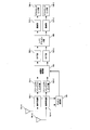
図2は、本実施形態に係る端末装置102-Aの送信機構成例を示す図である。なお、図2では、本発明の実施形態の説明に必要となるブロック(処理部)のみを示している。また、端末装置102-Aも同様の構成をもつことができる。なお、図2の端末装置102-A、102-Bは、図示していないが、基地局装置101が送信する下りリンク信号(下りリンク制御情報、RRCシグナリング、データ信号等)を受信する受信部を備える。
端末装置102-Aのデータを符号化した符号化ビット系列(コードワード)はスクランブリング部201-1およびスクランブリング部201-2に入力される。ここでコードワード数が1の場合、スクランブリング部201-2には何も入力されない。また、コードワード数は3以上であってもよく、その場合、コードワード数と同数のスクランブリング部が用意される。スクランブリング部201-1およびスクランブリング部201-2では、端末装置固有でコートワード固有のスクランブリングが適用される。スクランブリング部201-1~201-2の出力は、それぞれ変調部202-1~202-2に入力される。変調部201-1~201-2では、入力されたビット列をQPSKや64QAM等の変調シンボル(QPSK変調シンボル、QAM変調シンボル)に変換する処理がなされる。ここで、本実施形態では、遠方端末装置となる端末装置の変調方式は常にQPSKに限定されることを仮定して説明を行うが、これに限定されず、16QAMや64QAM等の変調方式を用いてもよい。なお、近傍端末装置となる端末装置の変調を行う変調部は、QPSKに限定されず、16QAMや64QAM等の変調方式が適用される。
変調部202-1~202-2の出力は、それぞれレイヤマッピング部203に入力される。レイヤマッピング部203では、端末装置102-Aが複数のレイヤを用いて送信を行う場合に、1または複数のコードワードを各レイヤに割り振る処理が適用される。以降の説明では、レイヤ数を2として説明を行うが、自然数であればどのような数であってもよい。レイヤマッピング部203の出力は、変形プリコーディング部204-1及び204-2に入力される。変形プリコーディング部では、レイヤマッピング部203から入力される変調シンボル系列に対して、DFT(Discrete Fourier Transform)による変形(Transform)を行う。ただし、DFT-S-OFDM(DFT-spread-Orthogonal Frequency Division Multiplexing)ではなくOFDMで伝送を行う場合は、変形プリコーディング部204-1および204-2では何も行わない。変形プリコーディング部204-1および204-2の出力はプリコーディング部205に入力される。プリコーディング部205では、各レイヤを複数のアンテナポートから送信するためのプリコーディングを行う。ここで、プリコーディングは変形プリコーディング部204-1および204-2での処理、つまりDFTを適用したか否か(あるいはPAPR(Peak to Average Power Ratio)が高い伝送方式か否か)に応じて、異なるプリコーディングを適用してもよい。また図2では送信アンテナ数(アンテナポート数)を2として説明を行ったが、レイヤ数以上の自然数であればどのような数であってもよい。プリコーディング部205の出力は、リソースエレメントマッピング部206-1および206-1に入力される。リソースエレメントマッピング部206では、プリコーディング部205から入力された信号を、任意の無線リソース(リソースエレメント、サブキャリア)に配置する。なお、どのリソースエレメントを用いるかは、図示されていないスケジューリング部からの入力によって決定される。またリソースマッピング部206-1および206-2では、制御情報生成部から入力される制御情報(例えばDCI(Downlink Control Information))、および参照信号生成部から入力される参照信号(DM-RS;DeModulation-Reference Signal、CRS;Common Reference Signal、CSI-RS;Channel Statement Information-Reference Signalなど)を所定のリソースエレメントに配置する処理も合わせて行われる。DM-RS、CSI-RSは、端末固有の参照信号である。CRSは、セル固有の参照信号である、DM-RSは、データを復調する際に用いられる参照信号である。CSI-RSは、Measurementに用いられる参照信号である。CRSは、データ復調する際、または/およびMeasurementの際に用いることができる。
リソースエレメントマッピング部206-1および206-2の出力はそれぞれ、信号生成部207-1および207-2に入力される。信号生成部207-1および207-2では、リソースエレメントマッピング部206-1および206-2からの入力に対し、IFFT(Inverse Fast Fourier Transform)を適用し、CP(Cyclic Prefix)を付加する。なお、端末装置102-Aは、狭いサブキャリア間隔(つまり、長いOFDMシンボル長)を用いた伝送を行うため、ポイント数の多い(例えば2048ポイント)IFFTを適用する一方、端末装置102-Bは、広いサブキャリア間隔(つまり、短いOFDMシンボル長)を用いた伝送を行うため、ポイント数の少ない(例えば512ポイント)IFFTを適用する。さらに、D/A変換、送信電力制御、フィルタリング、アップコンバージョン等の処理を適用する。信号生成部207-1および207-2の出力は、アンテナ208-1および208-2から送信を行う。
ここで、eMBBよりもURLLCの方が高いエネルギー(電力スペクトル密度)で基地局装置101において受信されるように送信電力制御が行われてもよい。つまり、広いサブキャリア間隔を用いた通信を行う場合、狭いサブキャリア間隔を用いる場合と比較して電力を高くして送信してもよい。送信電力は、データがマッピングされる帯域幅、データの端末装置における目標受信電力、パスロス等の構成要素によって、設定される。例えば、送信電力は、前記目標受信電力によって、広いサブキャリア間隔を用いた通信を行う場合、狭いサブキャリア間隔を用いる場合と比較して電力を高く設定される。前記目標受信電力は、RRCによって、端末装置固有または/およびセル固有に設定することができる。さらに、送信電力は、前記構成要素によって算出される送信電力に対する補正項等によって、調整してもよい。例えば、送信電力は、サブキャリア間隔固有の補正項によって、前記前記構成要素によって算出される送信電力に対して、調整される。送信電力は、前記補正項によって、広いサブキャリア間隔を用いた通信を行う場合、狭いサブキャリア間隔を用いる場合と比較して電力を高くなるように調整される。前記補正項は、RRCまたは/およびDCIを用いて、基地局装置から通知されてもよい。
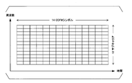
次にリソースマッピング部が行う無線フレーム(サブフレーム、スロット、ミニスロット)構成について説明を行う。図3にサブキャリア間隔が15kHzの時のリソースブロックを記載する。15kHzの場合、1リソースブロックは12サブキャリア、14OFDMシンボルからなり、リソースブロック単位の割当が行われる。図4にサブキャリア間隔が30kHzの時のリソースブロックを記載する。30kHzの場合、1リソースブロックは6サブキャリア、28OFDMシンボルからなるが、リソースブロック単位の割当だけではなく、1または複数のOFDMシンボル単位の割当が行われる。つまり時間的に、サブキャリア間隔が15kHzの端末が使用するリソースブロックの一部で、30kHzの端末が信号を送信することができる。
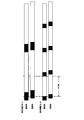
次に、本実施形態にかかるフレーム構成について説明を行う。図5は15kHzのサブキャリア間隔(SCS;Sub-Carrier Spacing)の端末装置と30kHzのサブキャリア間隔の端末装置のOFDMシンボルを記載している。図に示すように、SCSが30kHzの端末装置102-Bに対するFFT窓において、SCSが15kHzの端末装置102-Aの直接波による受信信号と遅延波による受信信号は周期性を満たさず、干渉となってしまう。この結果、OFDMシンボルが参照信号(パイロットシンボル)を含む場合、チャネル推定精度が劣化してしまう。
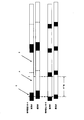
図6に端末装置102-Aが、参照信号を含むOFDMシンボルにおいて、同じ信号を繰り返して送信する場合を示す。つまり図中のOFDMシンボルの前半(A)とOFDMシンボルの後半(B)で、同じ信号を送信する。この結果、OFDMシンボルのCP(C)はBの後方のコピーであると共に、Aの後方のコピーでもあることになる。結果として、SCSが30kHzの端末装置のFFT窓において、端末装置102-Aの直接波による受信信号と遅延波による受信信号は、周期性を満たすことになる。結果としてOFDMシンボル長が異なることによる干渉は存在しなくなるため、干渉のないチャネル推定を行うことができる。なお図6ではOFDMシンボルの後半(B)でOFDMシンボルの前半(A)と同じ信号を送信しているが、無送信区間としてもよい。無送信区間とすることで端末装置102-Bのデータと干渉することを避けることができる上、消費電力も削減できる。なおCP(C)の区間は、参照信号を送信する前半(A)の後方をコピーしてもよいし、後半(B)の後方をコピー、つまり無送信区間としてもよい。さらにCP(C)は、他のOFDMシンボルや所定に依らず、端末装置102-B、つまり他の端末装置のCP長やOFDM長に応じて決定されてもよい。
端末装置102-Aが、信号を繰り返して送信するか否かは、基地局装置101から通知される。基地局装置は、端末装置102-Aと空間多重される端末装置が用いるSCSに応じて、繰り返し数を端末装置102-Aに通知する。例えば、端末装置102-AのSCSが15kHz、端末装置102-BのSCSが30kHzの場合、基地局装置101は繰り返し数が2であることを端末装置102-Aに通知する。また端末装置102-BのSCSが60kHzの場合、基地局装置101は繰り返し数が4であることを端末装置102-Aに通知する。端末装置102-Aのリソースエレメントマッピング部は、参照信号が含まれるOFDMシンボルは基地局装置から通知される繰り返し数を満たすように信号を形成する。端末装置102-Aは、繰り返しに関する情報を受信した場合、信号を繰り返すと判断してもよい。端末装置102-Aは、繰り返しに関する情報を受信しない場合、繰り返しを行わず、信号を送信すると判断する。端末装置102-Aは、繰り返しに関する情報を受信しない場合、デフォルトの参照信号の設定によって、信号を送信すると判断する。さらに、端末装置102-Aは、繰り返しに関する情報を受信した場合、繰り返しに関する情報に含まれる繰り返し数を充たすように信号を形成する。なお、基地局装置101から通知される繰り返し数に関する情報は、DCIを用いて動的に通知されてもよいし、上位層(例えばRRC)を用いて準静的に通知されてもよいし、システム情報(System Information Broadcast、SIB)としてブロードキャスト、あるいはグループキャストされてもよい。さらに繰り返し数に関する情報は、繰り返し数ではなく、繰り返し元となる系列の長さであってもよい。例えばSCSが15kHzの端末装置とSCSが30kHzの端末装置が空間多重される場合、SCSが30kHzの端末装置のIFFTサイズである1024を示す情報を、SCSが15kHzの端末装置に通知してもよい。つまり繰り返し数は、他の設定情報に関連付けられることによって、暗黙的に通知されてもよい。
繰り返し数に関する情報は、サブキャリア間隔インデックスによって、前記サブキャリア間隔と関連づけることもできる。基地局装置は、サブキャリア間隔インデックスを端末装置に送信することで、サブキャリア間隔及び繰り返し数を通知することができる。サブキャリア間隔インデックスは、DCI/RRCを用いて、送信されうる。また、基地局装置は、繰り返し数に関する情報またはサブキャリア間隔インデックスを、ACK/NACKの信号と共に、送信してもよい。端末装置は、前記繰り返し数に関する情報またはサブキャリア間隔インデックスに従って、信号を再送する。
次に、リソースエレメントマッピング部における具体的な処理について説明を行う。時間領域で信号波形が繰り返し出力されればどのような構成であってもよいが、本実施形態では、2つの方法について説明を行う。1つ目の方法は、端末装置102-Aが、参照信号が含まれるOFDMシンボルに対しては、他のOFDMシンボルの半分のIFFTサイズである1024ポイントIFFTを用いることを想定し、リソースマッピングを行う。例えば、2048ポイントの周波数インデックスの場合に、X番目の周波数インデックスからX+G番目の周波数インデックスに割り当てる場合、1024ポイントを想定した場合、X/2番目から(X+G)/2番目の周波数インデックスに参照信号を割り当てる。その後、信号生成部のIFFTで、他のOFDMシンボルの半分のIFFTサイズのIFFTを適用し、生成した信号を2回繰り返し、CPを付加する方法である。この方法によれば小さなサイズのFFTを1度行えばよいため、計算量を削減することができる。2つ目の方法は、リソースエレメントマッピング部への出力に対してゼロ(ヌルキャリア)を挿入する方法である。例えば入力される信号がa、b、c、d、…、zである場合、リソースエレメントマッピング部は、a、0、b,0、c、0、d、0、…0、z、0を生成し、所定のリソースにマッピングする。信号生成部では他のOFDMシンボルと同様のサイズのIFFTを行うことで信号を2回繰り返した信号を生成することができる。なお、入力される信号a、b、c、d、…、zは、全てが参照信号であってもよいし、一部のみが参照信号であり、他の信号はデータ信号や制御情報信号であってもよい。
上記では、OFDMシンボルの先頭にCPを付加することを記載したが、CPではなくゼロ区間であってもよいし、所定の系列であってもよい。
端末装置102-Aおよび端末装置102-Bの送信する参照信号は、分離される必要があるため、FDMAあるいはTDMAあるいはCDMA等で分離可能な構成を取る。例えばCDMAの場合、端末装置毎に異なる拡散符号(循環遅延および/もしくはWalsh行列)を与えればよい。LTEでは空間多重された参照信号を分離するため、サイクリックシフト(CS)や直交カバーコード(OCC)を用いて分離している。隣接サブキャリアで所定の回転量を与えることで、異なる回転量が与えられた信号と直交した信号を生成することができる。本実施形態においては、ヌルキャリア(振幅がゼロのサブキャリア)ではない隣接サブキャリアとの回転量が一定となるようにCSを適用することで、直交した参照信号を形成することができる。
次に端末装置102-Aおよび端末装置102-Bが送信した信号を受信する基地局装置101について説明を行う。図7は、本実施形態に係る基地局装置102の受信機構成例を示す図である。なお、図7では、本発明の実施形態の説明に必要となるブロック(処理部)のみを示している。また、図示していないが、基地局装置101は、端末装置102-A、102-Bが送信した上りリンク制御情報(UCI;Uplink Control Information)、RRCシグナリング(Capability等)、データ信号)を送信する送信部を備える。
端末装置102-Aおよび端末装置102-Bが送信した信号は、受信アンテナ701-1および受信アンテナ701-2で受信される。ここで受信アンテナ数を2として説明を行うが、1本でも良いし3本以上であってもよい。受信アンテナで受信した信号に対して信号受信部702-1および信号受信部702-2では、ダウンコンバージョン、A/D変換、CPの除去、FFTの適用等が行われる。ここでは、端末装置102-Aの復調について説明を行うが、端末装置102-Bの復調を行う場合、端末装置102-Bの送信機で用いられたIFFTのポイント数によってFFTを行う。またA/D変換後の参照信号を含む信号は、チャネル推定部709に入力される。チャネル推定部での処理については後述する。信号受信部702-1および信号受信部702-の出力はリソースエレメントデマッピング部703-1およびリソースエレメントデマッピング部703-2にそれぞれ入力される。リソースエレメントデマッピング部703-1および703-2にて、図示されていないスケジューリング部から入力されるスケジューリング情報によって、端末装置102-Aとの通信に用いられたリソースエレメントを抽出する。リソースエレメントデマッピング部703の出力は信号検出部904に入力される。伝搬路補償部704では、伝搬路の影響を補償する処理が適用される。受信アンテナが複数存在する場合は、伝搬路補償部704において空間フィルタリングやMLDを適用することで、端末装置102-A宛の信号のみを検出する。伝搬路補償部704の出力は、IDFT部705-1およびIDFT部705-2に入力される。本実施形態ではレイヤ数が2として説明を行うが、1であっても3以上であってもよい。IDFT部705-1およびIDFT部705-2では、IDFTを適用することで時間領域信号への変換が行われる。ここで、IDFTの適用は送信機である図2の変形プリコーディング部204-1および変形プリコーディング部204-2でプリコーディング(DFT)を適用した場合にのみ適用される。プリコーディングがDFTの場合、IDFT部705-1およびIDFT部705-2では、IDFTを適用するが、これに限定されず、プリコーディング部での変換の逆変換を行う。さらにレイヤ毎に適用するか否かを決定できる。IDFT部705-1およびIDFT部705-2の出力は、レイヤデマッピング部706に入力される。レイヤデマッピング部706では、端末装置102-Aが送信した信号が複数のレイヤ(ストリーム)からなる場合、コードワードへの変換が行われる。レイヤデマッピング部706の出力は、復調部707-1および復調部707-2に入力される。復調部707-1および復調部707-2では、入力された受信信号系列からビット系列のLLR(Log Likelihood Ratio)を算出する処理が行われる。復調部707-1および復調部707-2が出力するビットLLR列は、デスクランブリング部708-1およびデスクランブリング部708-2に入力される。デスクランブリング部708-1およびデスクランブリング部708-2では、端末装置固有のスクランブリングが解除される。デスクランブリング部デスクランブリング部708-1およびデスクランブリング部708-2が出力する符号化ビット列は、受信装置内で復号等の処理が適用される。
次に本実施形態のチャネル推定部709について説明を行う。端末装置102-Aの信号検出のためのチャネル推定部709は、端末装置102-Aが使用する無線リソースにおいて他の端末装置(例えば無線端末装置102-B)が存在するか否かによって処理が異なる。他の端末装置が存在しない場合、チャネル推定部709は、送信機において時間領域で繰り返された信号を受信しないため、大きなFFTポイント数(例えば2048)でFFTを行う。一方、他の端末装置が存在する場合、時間領域で繰り返された信号を受信するため、チャネル推定部709は、小さなFFTポイント数(例えば2048)でFFTを行う。つまり図6のFFT窓においてFFTを適用する。したがって、チャネル推定部709は、データ(PUSCH)とは異なるサブキャリア数(間隔)の受信信号によってチャネル推定を行うことになる。なお、他の端末装置が存在するか否かは基地局装置101内のスケジューリング部から通知される。上記はアップリンクで説明を行ったが、ダウンリンクの場合、基地局装置101から端末装置102-Aおよび端末装置102-Bに繰り返しに関する情報が通知される。通知方法はDCIを用いて動的に行ってもよいし、RRCを用いて準静的に行ってもよい。
図8にチャネル推定部709でのチャネル推定法の一例について説明を行う。(a)に示すように、他の端末装置が存在する場合、チャネル推定部709は、データ部より少ないFFTポイント数でチャネル推定を行う。本来のFFTポイント数の半分のFFTによってチャネル推定を行った場合、(b)のように0を挿入して、周波数インデックス数を2倍にする。ここで本来のFFTポイント数の4倍の場合、1つのスペクトルに対して3つの0を挿入して4倍の周波数インデックス数とする。その後(b)の奇数のスペクトルを用いて補間処理を適用し、(c)のようなすべての周波数インデックスにおけるチャネル推定を行う。ここで、補間方法としては線形補間(1次補間)やMMSE補間等、既存の補間方法を用いることができる。また、上記の説明ではOFDMシンボルの前半、つまり図6のAの部分のみを用いてチャネル推定を行う例を説明したが、Bにも参照信号が含まれるため、Bを用いてチャネル推定を行ってもよい。ただし端末装置102-Bと無線リソースを共有する場合は、端末装置102-Bのデータを復号し、得られたデータから受信信号レプリカを生成し、受信信号から減算してからチャネル推定を行ったり、端末装置102-Bからの干渉をフィルタリング等によって抑圧したりしてからチャネル推定を行う。得られたチャネル推定結果は伝搬路補償部に入力される。
本発明の一態様に関わる装置で動作するプログラムは、本発明の一態様に関わる上述した実施形態の機能を実現するように、Central Processing Unit(CPU)等を制御してコンピュータを機能させるプログラムであっても良い。プログラムあるいはプログラムによって取り扱われる情報は、処理時に一時的にRandom Access Memory(RAM)などの揮発性メモリに読み込まれ、あるいはフラッシュメモリなどの不揮発性メモリやHard Disk Drive(HDD)に格納され、必要に応じてCPUによって読み出し、修正・書き込みが行なわれる。
尚、上述した実施形態における装置の一部、をコンピュータで実現するようにしても良い。その場合、実施形態の機能を実現するためのプログラムをコンピュータが読み取り可能な記録媒体に記録しても良い。この記録媒体に記録されたプログラムをコンピュータシステムに読み込ませ、実行することによって実現しても良い。ここでいう「コンピュータシステム」とは、装置に内蔵されたコンピュータシステムであって、オペレーティングシステムや周辺機器等のハードウェアを含むものとする。また、「コンピュータが読み取り可能な記録媒体」とは、半導体記録媒体、光記録媒体、磁気記録媒体等のいずれであっても良い。
さらに「コンピュータが読み取り可能な記録媒体」とは、インターネット等のネットワークや電話回線等の通信回線を介してプログラムを送信する場合の通信線のように、短時間、動的にプログラムを保持するもの、その場合のサーバやクライアントとなるコンピュータシステム内部の揮発性メモリのように、一定時間プログラムを保持しているものも含んでも良い。また上記プログラムは、前述した機能の一部を実現するためのものであっても良く、さらに前述した機能をコンピュータシステムにすでに記録されているプログラムとの組み合わせで実現できるものであっても良い。
また、上述した実施形態に用いた装置の各機能ブロック、または諸特徴は、電気回路、すなわち典型的には集積回路あるいは複数の集積回路で実装または実行され得る。本明細書で述べられた機能を実行するように設計された電気回路は、汎用用途プロセッサ、デジタルシグナルプロセッサ(DSP)、特定用途向け集積回路(ASIC)、フィールドプログラマブルゲートアレイ(FPGA)、またはその他のプログラマブル論理デバイス、ディスクリートゲートまたはトランジスタロジック、ディスクリートハードウェア部品、またはこれらを組み合わせたものを含んでよい。汎用用途プロセッサは、マイクロプロセッサであってもよいし、従来型のプロセッサ、コントローラ、マイクロコントローラ、またはステートマシンであっても良い。前述した電気回路は、デジタル回路で構成されていてもよいし、アナログ回路で構成されていてもよい。また、半導体技術の進歩により現在の集積回路に代替する集積回路化の技術が出現した場合、当該技術による集積回路を用いることも可能である。
なお、本願発明は上述の実施形態に限定されるものではない。実施形態では、装置の一例を記載したが、本願発明は、これに限定されるものではなく、屋内外に設置される据え置き型、または非可動型の電子機器、たとえば、AV機器、キッチン機器、掃除・洗濯機器、空調機器、オフィス機器、自動販売機、その他生活機器などの端末装置もしくは通信装置に適用出来る。
以上、この発明の実施形態に関して図面を参照して詳述してきたが、具体的な構成はこの実施形態に限られるものではなく、この発明の要旨を逸脱しない範囲の設計変更等も含まれる。また、本発明の一態様は、請求項に示した範囲で種々の変更が可能であり、異なる実施形態にそれぞれ開示された技術的手段を適宜組み合わせて得られる実施形態についても本発明の技術的範囲に含まれる。また、上記各実施形態に記載された要素であり、同様の効果を奏する要素同士を置換した構成も含まれる。
本発明の一態様は、基地局装置や端末装置及びその通信方法に用いて好適である。本発明の一態様は、例えば、通信システム、通信機器(例えば、携帯電話装置、基地局装置、無線LAN装置、或いはセンサーデバイス)、集積回路(例えば、通信チップ)、又はプログラム等において、利用することができる。
101・・・基地局装置、102-A、102-B・・・端末装置、201-1、201-2・・・スクランブリング部、202-1、202-2・・・変調部、203・・・レイヤマッピング部、204-1、204-2・・・変形プリコーディング部、205・・・プリコーディング部、206-1、206-2・・・リソースエレメントマッピング部、207-1、207-2・・・信号生成部、208-1、208-2・・・送信アンテナ、209・・・制御情報生成部、210・・・参照信号生成部、701-1、701-2・・・受信アンテナ、702-1、702-2・・・信号受信部、703-1、703-2・・・リソースエレメントデマッピング部、704・・・伝搬路補償部、705-1、705-2・・・IDFT部、706・・・レイヤデマッピング部、707-1、707-2・・・復調部、708-1、708-2・・・デスクランブリング部、909・・・チャネル推定部
Claims (6)
- 基地局装置と通信する端末装置であって、
前記基地局装置から、下りリンク制御情報を受信する受信部と、
データ信号と参照信号をサブキャリアにマッピングするリソースエレメントマッピング部と、前記参照信号と前記データ信号を含む送信信号を送信する信号生成部と、を備え、
前記下りリンク制御情報は、参照信号の繰り返し数に関する情報を含み、
前記リソースエレメントマッピング部は、前記参照信号の繰り返しに関する情報に応じて、前記参照信号の繰り返し数を変更する端末装置。 - 前記繰り返し数に関する情報は、前記サブキャリアのサブキャリア間隔に応じて設定される、請求項1に記載の端末装置。
- 前記リソースエレメントマッピング部は、前記参照信号の繰り返しに関する情報に応じて、参照信号を含むOFDMシンボルにマッピングするデータ信号の繰り返し数を変更する請求項1に記載の端末装置。
- 端末装置と通信する基地局装置であって、
下りリンク制御情報を前記端末装置に送信する送信部と、
複数のサブキャリア間隔で生成された受信信号を受信する信号受信部と、を備え、
前記送信部は、前記受信信号のうち、少なくとも参照信号が含まれるOFDMシンボルにおいて、同じ信号が繰り返されて生成されるように、参照信号の繰り返し数に関する情報を端末装置に通知する基地局装置。 - 基地局装置と通信する端末装置であって、
前記基地局装置から、下りリンク制御情報を受信する受信ステップと、
データ信号と参照信号をサブキャリアにマッピングするリソースエレメントマッピングステップと、前記参照信号と前記データ信号を含む送信信号を送信する信号生成ステップと、を有し、
前記下りリンク制御情報は、参照信号の繰り返し数に関する情報を含み、
前記リソースエレメントマッピングステップは、前記参照信号の繰り返しに関する情報に応じて、前記参照信号の繰り返し数を変更する端末装置。 - 端末装置と通信する基地局装置の通信方法であって、
下りリンク制御情報を前記端末装置へ送信する送信ステップと、
複数のサブキャリア間隔で生成された受信信号を受信する信号受信ステップと、を有し、
前記送信ステップは、前記受信信号のうち、少なくとも参照信号が含まれるOFDMシンボルにおいて、同じ信号が繰り返されて生成されるように、参照信号の繰り返し数に関する情報を前記端末装置に通知する通信方法。
Priority Applications (1)
| Application Number | Priority Date | Filing Date | Title |
|---|---|---|---|
| US16/470,424 US10917221B2 (en) | 2016-12-21 | 2017-12-20 | Base station apparatus, terminal apparatus, and communication method |
Applications Claiming Priority (2)
| Application Number | Priority Date | Filing Date | Title |
|---|---|---|---|
| JP2016248067A JP2020031251A (ja) | 2016-12-21 | 2016-12-21 | 基地局装置、端末装置及び通信方法 |
| JP2016-248067 | 2016-12-21 |
Publications (1)
| Publication Number | Publication Date |
|---|---|
| WO2018117139A1 true WO2018117139A1 (ja) | 2018-06-28 |
Family
ID=62627346
Family Applications (1)
| Application Number | Title | Priority Date | Filing Date |
|---|---|---|---|
| PCT/JP2017/045663 Ceased WO2018117139A1 (ja) | 2016-12-21 | 2017-12-20 | 基地局装置、端末装置及び通信方法 |
Country Status (3)
| Country | Link |
|---|---|
| US (1) | US10917221B2 (ja) |
| JP (1) | JP2020031251A (ja) |
| WO (1) | WO2018117139A1 (ja) |
Cited By (1)
| Publication number | Priority date | Publication date | Assignee | Title |
|---|---|---|---|---|
| US20210399934A1 (en) * | 2018-10-02 | 2021-12-23 | Huawei Technologies Co., Ltd. | System and Method for Reducing Power Consumption Using Power Saving Reference Signals |
Families Citing this family (2)
| Publication number | Priority date | Publication date | Assignee | Title |
|---|---|---|---|---|
| WO2019126948A1 (zh) * | 2017-12-25 | 2019-07-04 | 华为技术有限公司 | 一种参数调整方法及相关设备 |
| US20250184200A1 (en) * | 2022-03-11 | 2025-06-05 | Sony Group Corporation | Communication device and communication method |
Citations (1)
| Publication number | Priority date | Publication date | Assignee | Title |
|---|---|---|---|---|
| US20150009951A1 (en) * | 2013-07-02 | 2015-01-08 | Samsung Electronics Co., Ltd. | Methods and apparatus for sounding channel operation in millimeter wave communication systems |
Family Cites Families (2)
| Publication number | Priority date | Publication date | Assignee | Title |
|---|---|---|---|---|
| JP5061892B2 (ja) * | 2007-12-28 | 2012-10-31 | 富士通株式会社 | 無線通信システムにおける信号多重方法、送信局及び受信局 |
| US10638474B2 (en) * | 2016-04-21 | 2020-04-28 | Qualcomm Incorporated | Different numerology for signal transmission |
-
2016
- 2016-12-21 JP JP2016248067A patent/JP2020031251A/ja active Pending
-
2017
- 2017-12-20 WO PCT/JP2017/045663 patent/WO2018117139A1/ja not_active Ceased
- 2017-12-20 US US16/470,424 patent/US10917221B2/en active Active
Patent Citations (1)
| Publication number | Priority date | Publication date | Assignee | Title |
|---|---|---|---|---|
| US20150009951A1 (en) * | 2013-07-02 | 2015-01-08 | Samsung Electronics Co., Ltd. | Methods and apparatus for sounding channel operation in millimeter wave communication systems |
Non-Patent Citations (3)
| Title |
|---|
| "ZTE Microelectronics", 3GPP TSG RAN WG1 MEETING #87, R1-1611267, 18 November 2016 (2016-11-18), XP051175248 * |
| ERICSSON: "Summary of offline discussion on UL Control Channels", 3GPP TSG RAN WG1 MEETING #87, R1-1613349, 19 November 2016 (2016-11-19), XP051191213 * |
| LG ELECTRONICS: "Design of short duration UL control channel for NR", 3GPP TSG RAN WG1 MEETING #87, R1-1611843, 18 November 2016 (2016-11-18), XP051175811 * |
Cited By (2)
| Publication number | Priority date | Publication date | Assignee | Title |
|---|---|---|---|---|
| US20210399934A1 (en) * | 2018-10-02 | 2021-12-23 | Huawei Technologies Co., Ltd. | System and Method for Reducing Power Consumption Using Power Saving Reference Signals |
| US12267195B2 (en) * | 2018-10-02 | 2025-04-01 | Huawei Technologies Co., Ltd. | System and method for reducing power consumption using power saving reference signals |
Also Published As
| Publication number | Publication date |
|---|---|
| US20190312714A1 (en) | 2019-10-10 |
| US10917221B2 (en) | 2021-02-09 |
| JP2020031251A (ja) | 2020-02-27 |
Similar Documents
| Publication | Publication Date | Title |
|---|---|---|
| US11082192B2 (en) | Methods and systems for numerology determination of wireless communication systems | |
| EP3567784B1 (en) | Method and device for transmitting a reference signal | |
| CN110506397B (zh) | 高级无线通信系统中基于不等比特分配的高分辨率csi报告 | |
| EP3433970B1 (en) | Method and apparatus for transmitting and receiving reference signals in wireless communication | |
| US10069610B2 (en) | Method and apparatus for generating a reference signal sequence in a wireless communication system | |
| JP6178393B2 (ja) | アップリンク伝送時に、多重符号語ベースの単一ユーザmimoが用いられるシステムにおけるphich割当及び参照信号生成方法 | |
| JP2025131739A (ja) | Mu-mimoにおいて協調スケジューリングされるdmrsポートを示すためのシグナリング態様 | |
| JP5503756B2 (ja) | ダウンリンクpdsch電力設定のための方法及び装置 | |
| CN109560910B (zh) | 用于虚拟(基带)载波聚合宽带lte的设备、网络和方法 | |
| RU2696258C2 (ru) | Устройство связи и способ связи | |
| JP2020513171A (ja) | 位相追跡参照信号処理方法および装置 | |
| CN106411486B (zh) | 一种上行解调导频的发送接收方法及装置 | |
| US9237049B2 (en) | Wireless communication base station device, wireless communication mobile station device, and propagation path estimation method | |
| CN104937873A (zh) | 无线通信系统中的方法和节点 | |
| JPWO2018008739A1 (ja) | 基地局装置、端末装置、通信方法、および、集積回路 | |
| KR20140144208A (ko) | 기지국 장치, 단말 장치, 통신 방법, 집적 회로 및 통신 시스템 | |
| US20160143038A1 (en) | Terminal device, base station device, wireless communication system, and communication method | |
| CN110999117B (zh) | 用于先进无线通信系统中csi报告的波束选择的方法和装置 | |
| WO2018181283A1 (ja) | 基地局装置、端末装置及び通信方法 | |
| WO2016070829A1 (en) | System and method for transmission symbol arrangement for reducing mutual interference | |
| US10917221B2 (en) | Base station apparatus, terminal apparatus, and communication method | |
| CN117121414A (zh) | 用于传输参考信号的方法和装置 | |
| WO2023198123A1 (en) | Method and apparatus for increasing system capacity of demodulation reference signals | |
| CN102017559A (zh) | 在无线通信系统中传送控制信号的方法 | |
| WO2011052192A1 (ja) | 無線通信端末装置、無線通信基地局装置および系列番号決定方法 |
Legal Events
| Date | Code | Title | Description |
|---|---|---|---|
| 121 | Ep: the epo has been informed by wipo that ep was designated in this application |
Ref document number: 17885113 Country of ref document: EP Kind code of ref document: A1 |
|
| NENP | Non-entry into the national phase |
Ref country code: DE |
|
| 122 | Ep: pct application non-entry in european phase |
Ref document number: 17885113 Country of ref document: EP Kind code of ref document: A1 |
|
| NENP | Non-entry into the national phase |
Ref country code: JP |