WO2018116605A1 - 画像処理装置、画像処理方法及びプログラム - Google Patents
画像処理装置、画像処理方法及びプログラム Download PDFInfo
- Publication number
- WO2018116605A1 WO2018116605A1 PCT/JP2017/037600 JP2017037600W WO2018116605A1 WO 2018116605 A1 WO2018116605 A1 WO 2018116605A1 JP 2017037600 W JP2017037600 W JP 2017037600W WO 2018116605 A1 WO2018116605 A1 WO 2018116605A1
- Authority
- WO
- WIPO (PCT)
- Prior art keywords
- image
- unit
- image processing
- processing
- signal
- Prior art date
Links
Images


Classifications
-
- H—ELECTRICITY
- H04—ELECTRIC COMMUNICATION TECHNIQUE
- H04N—PICTORIAL COMMUNICATION, e.g. TELEVISION
- H04N1/00—Scanning, transmission or reproduction of documents or the like, e.g. facsimile transmission; Details thereof
- H04N1/41—Bandwidth or redundancy reduction
-
- G—PHYSICS
- G06—COMPUTING OR CALCULATING; COUNTING
- G06T—IMAGE DATA PROCESSING OR GENERATION, IN GENERAL
- G06T3/00—Geometric image transformations in the plane of the image
-
- H—ELECTRICITY
- H04—ELECTRIC COMMUNICATION TECHNIQUE
- H04N—PICTORIAL COMMUNICATION, e.g. TELEVISION
- H04N1/00—Scanning, transmission or reproduction of documents or the like, e.g. facsimile transmission; Details thereof
- H04N1/46—Colour picture communication systems
- H04N1/56—Processing of colour picture signals
- H04N1/60—Colour correction or control
-
- H—ELECTRICITY
- H04—ELECTRIC COMMUNICATION TECHNIQUE
- H04N—PICTORIAL COMMUNICATION, e.g. TELEVISION
- H04N1/00—Scanning, transmission or reproduction of documents or the like, e.g. facsimile transmission; Details thereof
- H04N1/46—Colour picture communication systems
- H04N1/64—Systems for the transmission or the storage of the colour picture signal; Details therefor, e.g. coding or decoding means therefor
- H04N1/642—Adapting to different types of images, e.g. characters, graphs, black and white image portions
-
- H—ELECTRICITY
- H04—ELECTRIC COMMUNICATION TECHNIQUE
- H04N—PICTORIAL COMMUNICATION, e.g. TELEVISION
- H04N19/00—Methods or arrangements for coding, decoding, compressing or decompressing digital video signals
- H04N19/10—Methods or arrangements for coding, decoding, compressing or decompressing digital video signals using adaptive coding
- H04N19/102—Methods or arrangements for coding, decoding, compressing or decompressing digital video signals using adaptive coding characterised by the element, parameter or selection affected or controlled by the adaptive coding
- H04N19/124—Quantisation
- H04N19/126—Details of normalisation or weighting functions, e.g. normalisation matrices or variable uniform quantisers
-
- H—ELECTRICITY
- H04—ELECTRIC COMMUNICATION TECHNIQUE
- H04N—PICTORIAL COMMUNICATION, e.g. TELEVISION
- H04N19/00—Methods or arrangements for coding, decoding, compressing or decompressing digital video signals
- H04N19/10—Methods or arrangements for coding, decoding, compressing or decompressing digital video signals using adaptive coding
- H04N19/134—Methods or arrangements for coding, decoding, compressing or decompressing digital video signals using adaptive coding characterised by the element, parameter or criterion affecting or controlling the adaptive coding
- H04N19/136—Incoming video signal characteristics or properties
- H04N19/14—Coding unit complexity, e.g. amount of activity or edge presence estimation
-
- H—ELECTRICITY
- H04—ELECTRIC COMMUNICATION TECHNIQUE
- H04N—PICTORIAL COMMUNICATION, e.g. TELEVISION
- H04N19/00—Methods or arrangements for coding, decoding, compressing or decompressing digital video signals
- H04N19/10—Methods or arrangements for coding, decoding, compressing or decompressing digital video signals using adaptive coding
- H04N19/134—Methods or arrangements for coding, decoding, compressing or decompressing digital video signals using adaptive coding characterised by the element, parameter or criterion affecting or controlling the adaptive coding
- H04N19/167—Position within a video image, e.g. region of interest [ROI]
-
- H—ELECTRICITY
- H04—ELECTRIC COMMUNICATION TECHNIQUE
- H04N—PICTORIAL COMMUNICATION, e.g. TELEVISION
- H04N19/00—Methods or arrangements for coding, decoding, compressing or decompressing digital video signals
- H04N19/10—Methods or arrangements for coding, decoding, compressing or decompressing digital video signals using adaptive coding
- H04N19/169—Methods or arrangements for coding, decoding, compressing or decompressing digital video signals using adaptive coding characterised by the coding unit, i.e. the structural portion or semantic portion of the video signal being the object or the subject of the adaptive coding
- H04N19/186—Methods or arrangements for coding, decoding, compressing or decompressing digital video signals using adaptive coding characterised by the coding unit, i.e. the structural portion or semantic portion of the video signal being the object or the subject of the adaptive coding the unit being a colour or a chrominance component
-
- H—ELECTRICITY
- H04—ELECTRIC COMMUNICATION TECHNIQUE
- H04N—PICTORIAL COMMUNICATION, e.g. TELEVISION
- H04N19/00—Methods or arrangements for coding, decoding, compressing or decompressing digital video signals
- H04N19/60—Methods or arrangements for coding, decoding, compressing or decompressing digital video signals using transform coding
-
- H—ELECTRICITY
- H04—ELECTRIC COMMUNICATION TECHNIQUE
- H04N—PICTORIAL COMMUNICATION, e.g. TELEVISION
- H04N23/00—Cameras or camera modules comprising electronic image sensors; Control thereof
- H04N23/10—Cameras or camera modules comprising electronic image sensors; Control thereof for generating image signals from different wavelengths
Definitions
- the present disclosure relates to an image processing apparatus, an image processing method, and a program.
- HDR High Dynamic Range
- SDR Standard Dynamic Range
- HLG Hybrid Log-Gamma
- ST2084 Spin-Log3
- An image processing apparatus includes a control unit that determines a parameter, and a processing unit that executes the image processing using the processing parameter determined by the control unit.
- an image processing method including: determining a processing parameter of the image processing method; and executing the image processing using the determined processing parameter.
- the processor of the image processing device is based on at least one of a transfer function related to conversion between light applied to an image and an image signal and a color gamut applied to the image.
- a program for functioning as a control unit that determines processing parameters for image processing on the image and a processing unit that executes the image processing using the processing parameters determined by the control unit is provided.
- FIG. 5 is an explanatory diagram for explaining a color gamut defined by 2020.
- FIG. It is explanatory drawing for demonstrating the influence which the difference in the classification of a transfer function has on an encoding difficulty level. It is explanatory drawing which shows the 1st example of a structure of the image processing system which concerns on one Embodiment. It is explanatory drawing which shows the 2nd example of a structure of the image processing system which concerns on one Embodiment.
- 1 is a block diagram illustrating a first example of a schematic configuration of an image processing apparatus according to a first embodiment. It is a block diagram which shows the 2nd example of schematic structure of the image processing apparatus which concerns on 1st Embodiment.
- FIG. 20 is a flowchart illustrating an example of a flow of image processing according to a modification described using FIG. 19.
- FIG. It is a block diagram which shows an example of the hardware constitutions of an apparatus. It is a figure showing roughly the whole operation room system composition. It is a figure which shows the example of a display of the operation screen in a concentrated operation panel. It is a figure which shows an example of the mode of the surgery to which the operating room system was applied. It is a block diagram which shows an example of a function structure of the camera head shown in FIG. 24, and CCU.
- FIG. 1A is an explanatory diagram for explaining the luminance dynamic range of the SDR video.
- the vertical axis in FIG. 1A represents luminance [nit].
- the maximum brightness in the natural world may reach 20000 nit, and the brightness of a general subject is, for example, about 12000 nit at the maximum.
- the upper limit of the dynamic range of the image sensor is lower than the maximum brightness in the natural world, and may be, for example, 4000 nits.
- An imaging apparatus such as a digital camera or a digital camcorder converts an electrical signal generated by photoelectrically converting incident light in an image sensor into, for example, a 10-bit digital image signal in a signal processing circuit subsequent to the image sensor.
- the digital image signal generated by the imaging device is encoded by a predetermined video encoding method (also referred to as a video codec) according to the purpose of an application such as transmission or recording, and converted into an encoded bit stream.
- a digital image signal acquired by decoding the encoded bit stream is provided to the display device, and the video is reproduced with a display luminance of 100 nits maximum.
- FIG. 1B is an explanatory diagram for explaining the luminance dynamic range of the HDR video.
- the imaging apparatus converts incident light to the image sensor into an analog electric signal, and further converts the analog electric signal into, for example, a 10-bit digital image signal.
- the HDR video signal format maintains the gradation of the high-luminance portion exceeding 100 nits during such conversion, and allows the video to be reproduced with a luminance up to the upper limit of several hundreds or thousands of nits.
- the digital image signal generated by the imaging device is also encoded by a predetermined video encoding method according to the purpose of the application, and converted into an encoded bit stream.
- a digital image signal obtained by decoding the encoded bitstream is provided to the display device, and the video is reproduced with a luminance dynamic range including display luminance higher than 100 nits.
- codec distortion Regardless of whether the video is an SDR video or an HDR video, when an image signal is encoded by a video encoding method including irreversible compression, image quality is deteriorated in an image reproduced based on the decoded image signal. Such image quality degradation is referred to as codec distortion in this specification.
- the degree of codec distortion can be evaluated by an index called PSNR (Peak Signal-to-Noise Ratio).
- PSNR Peak Signal-to-Noise Ratio
- H when coding efficiency is equal, H.
- the image quality of an image encoded / decoded by H.264 / AVC is higher than the image quality of an image encoded / decoded by MPEG-2.
- the image quality of an image encoded / decoded by H.265 / HEVC is H.265. It is higher than H.264 / AVC.
- evaluation of codec distortion is usually performed by comparing the original image input to the encoder and the decoded image output from the decoder. It is not well known how signal conversion performed during HDR image capture or display, or how dynamic range reduction or expansion affects codec distortion.
- the inventors have converted a large number of sample videos into image signals in the HDR signal format. After encoding and decoding by an encoder and decoder compliant with H.264 / AVC, an experiment was conducted to verify the image quality of an HDR video reproduced from a decoded image signal. As a result, it was recognized that there was a case where degradation of image quality that was not detected in the SDR video with the same sample was visually recognized in the HDR video that passed through the video codec. The deterioration of the image quality has occurred remarkably in a part of the image mainly in the form of block noise or mosquito noise.
- the degree of deterioration that occurs when the same 10-bit image signal is encoded by the same video encoding method is usually the same. Nevertheless, it is considered that the distortion that is not perceived (or difficult to perceive) in the SDR video is detected in the HDR video because the codec distortion is expanded together when the dynamic range of the decoded image signal is expanded.
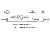
- FIG. 2A shows a state where codec distortion occurs in an image signal of an SDR video through encoding and decoding. Since the codec distortion is not enlarged when the SDR video is reproduced, the distortion is not perceived subjectively if the distortion is sufficiently small.
- FIG. 2B shows that the codec distortion still occurs in the image signal of the HDR video. When playing back an HDR video, the codec distortion is increased with the expansion of the dynamic range. As a result, the possibility of subjectively perceiving image quality degradation such as block noise or mosquito noise increases.
- Codec distortion can also be increased when format conversion from HDR to SDR is performed on an image signal expressed in the HDR signal format.
- FIG. 2C shows how the codec distortion is expanded through format conversion from HDR to SDR, that is, HDR-SDR conversion.
- the HDR-SDR conversion is generally an inverse function of a transfer function corresponding to a signal format for HDR (for example, obtained by decoding an encoded bit stream) into an original signal corresponding to the output of an image sensor.
- the codec distortion expanded in the former of these processes is not reduced in the reconversion to the signal format for SDR. Therefore, when the SDR video is reproduced based on the image signal after the HDR-SDR conversion, the enlarged codec distortion can be subjectively sensed.
- the codec distortion as described above is due to the performance of the video coding system itself, the distortion should occur uniformly.
- the above-described sample video verification confirmed that distortion is significant in the characteristic partial areas as exemplified below: -Specific color area (eg skin color area) -Flat areas (eg unpatterned building walls)
- the reason that distortion becomes prominent in these partial regions depends on the signal transfer function of the HDR signal format and the selection of the color gamut in the gradation or color in the real world, which means the individual code values of the color components. There is a difference.
- FIG. 3 illustrates an example of a typical SDR signal format OETF and an HDR signal format OETF.
- the horizontal axis represents the luminance dynamic range of light before conversion, and 100% corresponds to the luminance of 100 nits.
- the vertical axis represents the code value of the converted image signal. In the case of 10 bits, the code value can take values from 0 to 1023.
- the code value is particularly
- the difference in the slope of the transfer function is significant in a relatively large portion. This is because the image information is compressed at a higher compression ratio in the HDR case than in the SDR in such a portion, that is, in the HDR case, the same change in the code value is larger in the HDR case than in the SDR case. It means to express the change of key. Even when the transfer functions of the red (R) component, the green (G) component, and the blue (B) component are analyzed in the RGB color system, the relationship between HDR and SDR similar to the graph shown in FIG. Differences in signal transfer characteristics were confirmed.
- FIG. 4 shows SDR BT.
- a graph 709 shows how much the S-Log3 for HDR compresses image information.
- the horizontal axis in FIG. 4 represents the code value of a 10-bit image signal.
- the vertical axis represents BT.
- the ratio of the compression ratio of S-Log3 to the compression ratio of 709 is represented.
- the compression ratio of S-Log3 is BT. It is about 4 times the compression ratio of 709, and the compression ratio of S-Log3 becomes relatively higher as the code value increases.
- the image information is more strongly compressed in the HDR case than in the SDR case in the portion where the code value is relatively large.
- an EOTF Electro-Optical Transfer Function
- OETF Electro-Optical Transfer Function
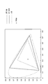
- FIG. 709 and BT. 5 is an explanatory diagram for explaining a color gamut defined by 2020.
- FIG. 5 Referring to FIG. 5, there is shown a color gamut graph in which a three-dimensional color space is mapped to a two-dimensional plane using predetermined constraint conditions. The cross mark in the graph indicates the position where white is mapped. The broken line in the graph indicates BT.
- BT. 709 shows the range of colors that can be represented according to 709.
- the solid line in the graph is BT.
- the range of colors that can be expressed according to 2020 is shown.
- the dotted lines in the graph indicate the range of colors that human vision can identify.
- BT. 2020 It is possible to express a variety of colors more than 709.
- BT. 709 can express about 75% of colors in the real world, whereas BT. 2020 is said to be able to express more than 99% of the colors.
- BT. 2020 may be used as the color gamut of the SDR video, or may be used as the color gamut of the HDR video.
- the quantization step determination method employed in some encoders can be expressed as the following equation (1).
- Q i represents a provisional quantization step of the i-th block in the image, which is determined so as to achieve a required compression rate according to the purpose of the application, regardless of the content of the image.
- Q ′ i represents an adjusted quantization step that is adjusted based on the coding difficulty level for each block.
- Act Bi represents an activity that is statistically calculated for the i-th block. The activity is one of the indexes of the encoding difficulty level, and is equal to the minimum value among the variances calculated for each of the plurality of sub-blocks in the block, for example.
- the function F (Act Bi ) is a function that takes an activity for each block (or another index of the encoding difficulty) as an argument and returns an adjustment coefficient for the quantization step.
- F 1 and F 2 Two examples of function F (Act Bi ) are shown below as F 1 and F 2 :
- Act PIC represents a representative value (e.g., average, median or maximum) of activity across the image.
- G is the case the activity Act Bi is equal to the activity Act PIC of the entire image, which corresponds to the ratio of adjusted quantization step Q'i for provisional quantization step Q i.
- the return value of the function F 1 (Act Bi ) changes between G / 2 and 2G.
- the remaining terms other than G on the right side of Expression (2) have a role of normalizing the activity Act Bi .
- G corresponds to the adjustment gain when the activity Act Bi is equal to zero (ie, the i-th block is quite flat).
- Equation (2) or Equation (3) if the image of the i-th block B i is relatively flat with respect to other blocks, the adjusted quantization step Q ′ i decreases to a smaller value. Adjusted. The smaller the quantization step used for a block, the finer the transform coefficients for that block are. This means that a larger amount of code is allocated to the block, that is, the gradation of the image of the block is maintained without being impaired.
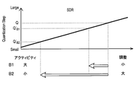
- Block B i is the i-th block set in the image Im1.
- the encoding difficulty level (arrow D1 in the lower left of the figure) calculated from the image signal when the SDR transfer function is applied.
- the calculated encoding difficulty (arrow D2 at the lower right of the figure) is smaller.
- a gain included in the function F of Equation (1) (for example, Equation (2) or Equation ( It is desirable that the basic adjustment gain G) of 3) is variably set so as to cancel the fluctuation of the statistical value accompanying the compression of information.
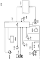
- FIG. 7A is an explanatory diagram illustrating a first example of the configuration of the image processing system according to the present embodiment.
- the image processing system 10a illustrated in FIG. 7A includes an imaging device 11, a signal processing device 14, and a server device 15.
- the imaging device 11 may be, for example, a digital video camera or a digital still camera, or any type of device having a video shooting function (for example, a monitoring camera, a Web camera, or an information terminal).
- the imaging device 11 captures the state of the real world using an image sensor and generates a primitive image signal.
- the signal processing device 14 may be a BPU (Baseband Processing Unit), for example, and is connected to the imaging device 11.
- the signal processing device 14 performs AD conversion and digital signal processing on the primitive image signal generated by the imaging device 11, and generates an image signal in a predetermined signal format.
- Digital signal processing performed by the signal processing device 14 may include, for example, gamma correction and color conversion.
- the signal processing device 14 may be configured integrally with the imaging device 11.
- the signal processing device 14 may generate an image signal with a transfer function and a color gamut selected from a plurality of candidates by a user via some user interface.
- a transfer function candidate is BT. 709, may include HLG, ST2084 and S-Log3 for HDR.
- the color gamut candidates are BT. 709, BT. 2020 and S-Gamut may be included.
- the signal processing device 14 multiplexes an auxiliary signal including an audio signal and metadata as necessary on the image signal generated as a result of signal conversion, and outputs the multiplexed signals to the server device 15.
- the server device 15 is an image processing device connected to the signal processing device 14 via a signal line conforming to a transmission protocol such as SDI (Serial Digital Interface) or HD-SDI.
- SDI Serial Digital Interface
- HD-SDI High Speed Digital Interface
- the server device 15 acquires the image signal transmitted from the signal processing device 14, encodes the image with a predetermined video encoding method, and generates an encoded bitstream 17a.
- the encoded bit stream 17a may be stored in a storage device inside or outside the server device 15, or may be transmitted to another device (for example, a display device) connected to the server device 15.
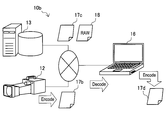
- FIG. 7B is an explanatory diagram illustrating a second example of the configuration of the image processing system according to the present embodiment.
- the image processing system 10b illustrated in FIG. 7B includes an imaging device 12, a storage device 13, and a terminal device 16.
- the imaging device 12 may be, for example, a digital video camera, a digital camcorder or a digital still camera, or any type of device having a video shooting function.
- the imaging device 12 captures a real-world situation using an image sensor and generates a primitive image signal.
- the imaging device 12 performs AD conversion and digital signal processing as described above in connection with the signal processing device 14, and generates an image signal in a predetermined signal format. Similar to the signal processing device 14, the imaging device 12 may generate an image signal with a transfer function and a color gamut selected by the user from a plurality of candidates via some user interface.
- the imaging device 12 encodes an image by a predetermined video encoding method based on an image signal generated as a result of signal conversion, and generates an encoded bit stream 17b.
- the encoded bit stream 17b may be stored as a video file, for example, or may be provided to the storage device 13 or the terminal device 16 via a network.
- the storage device 13 is a data storage that stores various video data.
- the storage device 13 may store a video file 17c generated by encoding an image using a predetermined video encoding method.
- the type of transfer function, the type of color gamut, and the video encoding method relating to conversion between light and image signal applied to the video content included in the video file are identified. Parameters can be included.
- the storage device 13 may store a RAW video file 18 that records an image signal before encoding (or before signal conversion) as RAW data.
- the storage device 13 provides a file that the user desires to reproduce or edit to the terminal device 16 via the network.
- the terminal device 16 is an image processing device having a function of reproducing or editing a video file generated by the imaging device 12 or stored by the storage device 13. For example, the terminal device 16 may decode a coded bitstream included in the video file 17b or 17c acquired from the imaging device 12 or the storage device 13 to generate a decoded image signal. Further, the terminal device 16 may perform dynamic range conversion (for example, HDR-SDR conversion or SDR-HDR conversion) on the decoded image generated as described above. Further, the terminal device 16 may encode the image signal included in the RAW video file 18 or the decoded image signal after dynamic range conversion by a predetermined video encoding method to generate the encoded bit stream 17d.
- dynamic range conversion for example, HDR-SDR conversion or SDR-HDR conversion
- the server device 15 in the example of FIG. 7A, and the imaging device 12 and the terminal device 16 in the example of FIG. 7B all have a function as an image processing device (that is, an encoder) that encodes an image.
- an image processing device that is, an encoder
- the quantum is based on at least one of a transfer function and a color gamut applied to the image (for example, based on their type or other attributes).
- the parameters relating to the digitization process are controlled, thereby reducing image quality degradation. From the next section, a specific and exemplary configuration of such an image processing apparatus will be described in detail.
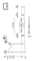
- FIG. 8A is a block diagram illustrating a first example of a schematic configuration of the image processing apparatus according to the present embodiment.
- the image processing apparatus 100a illustrated in FIG. 8A is, for example, the server apparatus 15 in the example of FIG. 7A, or the imaging apparatus 12 or the terminal apparatus 16 in the example of FIG. 7B (or an image processing module mounted on any of these apparatuses).
- the image processing apparatus 100a includes a signal acquisition unit 101, an information acquisition unit 103, an encoding unit 110, and a control unit 140.
- the signal acquisition unit 101 acquires an input image signal generated based on a transfer function related to conversion between light and an image signal.
- the signal acquisition unit 101 may acquire an input image signal from an external device via a transmission interface, or input from an imaging module and a signal processing module (not shown) configured integrally with the image processing device 100a. An image signal may be acquired.
- the information acquisition unit 103 acquires input information related to a transfer function and a color gamut applied to an image input to the encoding unit 110.
- the information acquisition unit 103 may acquire input information via a user interface included in the image processing apparatus 100a.
- the user interface may be provided by a physical input device such as a touch panel, a button, or a switch provided in the housing of the image processing apparatus 100a. Instead, the user interface may be provided as a GUI (Graphical User Interface) on a terminal device that is remotely connected via the communication interface.
- the input information includes at least a transfer function type indicating the type of transfer function applied to the image to be encoded and a color gamut type indicating the type of color gamut applied to the image.
- the user interface is, for example, BT. 709, the user may select one of a plurality of transfer function type candidates that may include HLG, ST2084, and S-Log3 for HDR.
- the user interface is BT. 709, BT.
- the user may select one of a plurality of color gamut type candidates that may include 2020 and S-Gamut.
- the information acquisition unit 103 may acquire input information from an auxiliary signal multiplexed with an input image signal.
- the auxiliary signal is received by the signal acquisition unit 101 during a period in which no image signal is transmitted on the signal line (for example, a blanking period). Then, the information acquisition unit 103 can acquire input information including the transfer function type and the color gamut type from the auxiliary signal separated in the signal acquisition unit 101.
- the information acquisition unit 103 may acquire input information required by accessing an external data source.
- the encoding unit 110 encodes an image represented by the image signal acquired by the signal acquisition unit 101, and generates an encoded bit stream.
- the encoding unit 110 is, for example, MPEG-2, H.264, or the like. H.264 / AVC or H.264
- the encoding process may be executed according to any video encoding method such as H.265 / HEVC.
- the encoding process executed by the encoding unit 110 typically includes various arithmetic processes such as prediction, orthogonal transform, quantization, and entropy encoding. Among them, quantization is used to achieve a required compression rate. This process includes lossy compression.
- the control unit 140 controls the quantization process executed in the encoding unit 110 based on at least one of the transfer function type and the color gamut type indicated by the input information acquired by the information acquisition unit 103. For example, the control unit 140 may cause the encoding unit 110 to adjust the quantization step in the quantization process with a different adjustment gain depending on what type of transfer function is applied to the image. Further, the control unit 140 may cause the encoding unit 110 to adjust the quantization step in the quantization process with a different adjustment gain depending on what type of color gamut is applied to the image.
- processing parameters such as a quantization step are determined based mainly on the transfer function and the type of color gamut will be described, but the processing parameters may be determined based on other attributes. The same applies to a second embodiment described later.
- FIG. 8B is a block diagram illustrating a second example of a schematic configuration of the image processing apparatus according to the present embodiment.
- the image processing apparatus 100b illustrated in FIG. 8B is also, for example, the server apparatus 15 in the example of FIG. 7A, or the image processing apparatus 12 or the terminal apparatus 16 in the example of FIG. Module).
- the image processing apparatus 100b includes a signal processing unit 102, an information acquisition unit 104, a storage unit 107, an encoding unit 110, and a control unit 140.
- the signal processing unit 102 acquires a primitive image signal input from the imaging device via some transmission interface or a signal line inside the device, or acquires an image signal from a video file stored in the storage unit 107. . Then, the signal processing unit 102 performs digital signal processing that can include, for example, gamma correction and color conversion on the primitive image signal, and generates an image signal to be encoded in a predetermined signal format. The transfer function and color gamut applied to the image by the signal processing unit 102 are determined based on the input information acquired by the information acquisition unit 104. Then, the signal processing unit 102 outputs the generated image signal to the encoding unit 110.
- the information acquisition unit 104 acquires input information related to a transfer function and a color gamut applied to the image encoded by the encoding unit 110.
- the information acquisition unit 104 may acquire input information via a user interface (provided by a physical input device or provided as a GUI) of the image processing apparatus 100b.
- the input information includes at least a transfer function type and a color gamut type.
- the user interface is, for example, BT. 709, the user may select one of a plurality of transfer function type candidates that may include HLG, ST2084, and S-Log3 for HDR.
- the user interface is BT. 709, BT.
- the user may select one of a plurality of color gamut type candidates that may include 2020 and S-Gamut.
- the storage unit 107 is a storage device for storing various video data.
- the storage unit 107 may store, for example, a video file that records a digital image signal before signal conversion.
- the user may store the video file acquired from the external storage medium in the storage unit 107 via an input / output interface (not shown) included in the image processing apparatus 100b.
- the storage unit 107 may store a video file including an encoded bit stream generated as a result of the encoding process executed by the encoding unit 110.
- the video file may be output to an external device upon request.
- the encoding unit 110 encodes an image represented by the image signal input from the signal processing unit 102 to generate an encoded bitstream.
- the control unit 140 controls the quantization process executed in the encoding unit 110 based on at least one of the transfer function type and the color gamut type indicated by the input information acquired by the information acquisition unit 104.
- the encoded bit stream generated by the encoding unit 110 may be transmitted to a device external to the image processing apparatus 100b, or may be stored as a video file by the storage unit 107.
- FIG. 9 is a block diagram illustrating an example of a detailed configuration of the encoding unit and the control unit according to the first embodiment.
- the encoding unit 110 includes a rearrangement buffer 111, a block setting unit 112, a subtraction unit 113, an orthogonal transformation unit 114, a quantization unit 115, a lossless encoding unit 116, and an inverse quantum.
- the rearrangement buffer 111 rearranges the image data of a series of images expressed by the image signal acquired by the signal acquisition unit 101 or the signal processing unit 102 according to a GOP (Group of Pictures) structure.
- the rearrangement buffer 111 outputs the rearranged image data to the block setting unit 112, the intra prediction unit 130, and the inter prediction unit 135.
- the block setting unit 112 divides each image corresponding to a picture into a plurality of blocks.
- MPEG-2 and H.264 In H.264 / AVC a picture is divided into a plurality of macroblocks having a fixed size in a grid pattern, and an encoding process is executed using each macroblock as a processing unit.
- the quantization process can be executed using a smaller sub-block set for each macroblock as a processing unit.
- H. In H.265 / HEVC a picture is divided into a plurality of coding units (Coding Units) having a variable size, and coding processing is executed with each CU as a processing unit.
- the quantization process can be executed with a smaller transform unit (Transform Unit) set in each CU as a processing unit.
- the subtraction unit 113 calculates prediction residual data that is the difference between the image data input from the block setting unit 112 and the prediction image data, and outputs the prediction residual data to the orthogonal transformation unit 114.
- the orthogonal transform unit 114 transforms the prediction residual data input from the subtraction unit 113 from spatial domain image data to frequency domain transform coefficient data.
- the orthogonal transformation executed by the orthogonal transformation unit 114 may be, for example, discrete cosine transformation or discrete sine transformation. Then, orthogonal transform section 114 outputs transform coefficient data to quantization section 115.
- the quantization unit 115 quantizes the transform coefficient data input from the orthogonal transform unit 114. For example, if the buffer or transmission path has a large free capacity relative to the size of the output encoded bit stream, the quantization step is set to a small value. Conversely, if the free capacity is small, the quantization step is set to a large value. obtain. More specifically, the quantization unit 115 tentatively determines a quantization step for each block so that a required compression rate is achieved, and further performs the quantization step according to the encoding difficulty level for each block. adjust. Then, the quantization unit 115 quantizes the transform coefficient data in the adjusted quantization step.
- the quantized transform coefficient data (hereinafter referred to as quantized data) is output to the lossless encoding unit 116 and the inverse quantization unit 121.
- the adjustment of the quantization step in the quantization unit 115 may be performed according to the equation (1) described above.
- the function F (Act Bi ) in equation (1) includes a processing parameter representing the adjustment gain of the quantization step. As the adjustment gain increases, the quantization step is adjusted to a smaller value, and as a result, the amount of code allocated to the block increases.
- An example of the parameter representing the adjustment gain is the basic adjustment gain G included in the equations (2) and (3).
- the quantization unit 115 performs a quantization process on each block in an adjusted quantization step that is adjusted based on the basic adjustment gain G and the encoding difficulty level Act Bi of each block. In the quantization unit 115, a different quantization step may be used for each color component. Further, the adjustment of the quantization step may be performed using different processing parameters for each color component.
- the lossless encoding unit 116 generates an encoded bitstream by encoding the quantized data input from the quantizing unit 115. Further, the lossless encoding unit 116 encodes various parameters referred to by the decoder, and inserts the encoded parameters into the encoded bitstream.
- the parameters encoded by the lossless encoding unit 116 may include information regarding transfer functions, information regarding color gamuts, and information regarding quantization parameters.
- the lossless encoding unit 116 outputs the generated encoded bit stream to an output destination according to the purpose of the application.
- the inverse quantization unit 121, the inverse orthogonal transform unit 122, and the addition unit 123 constitute a local decoder.
- the local decoder is responsible for reconstructing the original image from the encoded data.
- the inverse quantization unit 121 performs inverse quantization on the quantized data in the same quantization step as that used by the quantization unit 115, and restores transform coefficient data. Then, the inverse quantization unit 121 outputs the restored transform coefficient data to the inverse orthogonal transform unit 122.
- the inverse orthogonal transform unit 122 restores the prediction residual data by performing an inverse orthogonal transform process on the transform coefficient data input from the inverse quantization unit 121. Then, the inverse orthogonal transform unit 122 outputs the restored prediction residual data to the addition unit 123.
- the adding unit 123 generates decoded image data by adding the restored prediction residual data input from the inverse orthogonal transform unit 122 and the predicted image data generated by the intra prediction unit 130 or the inter prediction unit 135. To do. Then, the adding unit 123 outputs the generated decoded image data to the loop filter 124 and the frame memory 126.
- the loop filter 124 is an in-loop filter for the purpose of improving the image quality of the decoded image.
- the loop filter 124 may include, for example, a deblocking filter for reducing block distortion appearing in the decoded image.
- the loop filter 124 may include an adaptive offset filter for adding an edge offset or a band offset to the decoded image.
- the loop filter 124 outputs the decoded image data after filtering to the frame memory 126.
- the frame memory 126 stores the decoded image data before filtering input from the adder 123 and the decoded image data after application of the in-loop filter input from the loop filter 124.
- the switch 127 reads decoded image data before filtering used for intra prediction from the frame memory 126, and supplies the read decoded image data to the intra prediction unit 130 as reference image data. Further, the switch 127 reads out the decoded image data after filtering used for inter prediction from the frame memory 126 and supplies the read out decoded image data to the inter prediction unit 135 as reference image data.
- the mode selection unit 128 selects a prediction method for each block based on the cost comparison input from the intra prediction unit 130 and the inter prediction unit 135. For the block for which intra prediction is selected, the mode selection unit 128 outputs the prediction image data generated by the intra prediction unit 130 to the subtraction unit 113 and outputs information related to the intra prediction to the lossless encoding unit 116. For the block for which inter prediction is selected, the mode selection unit 128 outputs the prediction image data generated by the inter prediction unit 135 to the subtraction unit 113 and outputs information related to inter prediction to the lossless encoding unit 116. .
- the intra prediction unit 130 executes an intra prediction process based on the original image data and the decoded image data. For example, the intra prediction unit 130 evaluates a cost estimated to occur for each of a plurality of candidate modes included in the search range. Next, the intra prediction unit 130 selects the prediction mode that minimizes the cost as the best prediction mode. Further, the intra prediction unit 130 generates predicted image data according to the selected best prediction mode. Then, the intra prediction unit 130 outputs information related to intra prediction including prediction mode information indicating the best prediction mode, the corresponding cost, and prediction image data to the mode selection unit 128.
- the inter prediction unit 135 performs inter prediction processing (motion compensation) based on the original image data and the decoded image data. For example, the inter prediction unit 135 evaluates a cost estimated to occur for each of a plurality of candidate modes included in the search range. Next, the inter prediction unit 135 selects the prediction mode with the lowest cost as the best prediction mode. Further, the inter prediction unit 135 generates predicted image data according to the selected best prediction mode. Then, the inter prediction unit 135 outputs information related to inter prediction, corresponding costs, and predicted image data to the mode selection unit 128.
- inter prediction processing motion compensation
- control unit 140 includes a statistical calculation unit 141 and a quantization control unit 143.
- the statistical calculation unit 141 calculates the encoding difficulty level for the entire image and the encoding difficulty level for each block set in the image. For example, the statistical calculation unit 141 can calculate the activities Act Bi and Act PIC described above as the encoding difficulty level. Then, the statistical calculation unit 141 outputs the calculated statistical values to the quantization control unit 143.
- the quantization control unit 143 determines the transfer function and color gamut applied to the image to be encoded based on the input information input from the information acquisition unit 103 or 104. Then, the quantization control unit 143 determines a basic adjustment gain to be used for adjustment of the quantization step based on the transfer function, the color gamut, or a combination thereof. More specifically, the quantization control unit 143 sets the basic adjustment gain so as to cancel the influence of the change in the code value of the image signal caused by the difference in one or both of the transfer function and the color gamut on the quantization process. Can be determined. The effect here typically appears as a variation in the degree of codec distortion that occurs as a result of quantization and can also be perceived as subjective image quality degradation.
- the degree of codec distortion can be evaluated using the above-mentioned index called PSNR.
- PSNR the above-mentioned index
- the value of the basic adjustment gain can be determined, and the value of the basic adjustment gain determined as described above can be stored in the storage unit 107.
- the quantization control unit 143 reads, for example, one of those predetermined values corresponding to the transfer function or the color gamut, or a combination thereof from the storage unit 107, and adjusts the quantization step. It can be determined as the value of the basic adjustment gain to be used.
- FIG. 10 shows an image Im1 similar to that illustrated in FIG.
- the block B1 is located in a region having a relatively complicated image content in the image Im1
- the block B2 is located in a region having a relatively flat image content in the image Im1.
- 11 shows an example of adjustment of the quantization step in the SDR case (for example, the transfer function is BT.709).
- the quantization steps provisionally determined for the blocks B1 and B2 are both equal to Q. Higher (activity greater than) the quantization step of the block B1 of the encoding difficulty is adjusted to Q'B1.
- the quantization step of the block B2 having a lower encoding difficulty (less activity) is adjusted to Q ′ B2 smaller than Q ′ B1 .
- the range of these adjustments depends on the basic adjustment gain G SDR that is well designed for the SDR case.
- FIG. 12 shows an example of adjustment of the quantization step in the HDR case (for example, the transfer function is HLG) according to the existing method.
- the transfer function is HLG
- a fixed basic adjustment gain is used regardless of the transfer function and color gamut applied to the image.
- the encoding difficulty level calculated for images showing the same subject becomes a smaller value if the image information is more strongly compressed at the time of signal conversion, and the quantization step adjustment formula (1) accordingly.
- the adjustment range at is also smaller. Consequently, in the case of FIG. 12, the quantization step of the block B1 is adjusted to Q'' B1 greater than Q'B1, the quantization step of the block B2 is to Q'' B2 greater than Q'B2 And can be adjusted.
- FIG. 13 shows an example of adjustment of the quantization step according to the present embodiment.
- the quantization control unit 143 uses the basic adjustment used when adjusting the quantization step based on at least one of the transfer function and the color gamut applied to the image. Switch the gain.
- the basic adjustment gain G HDR use of the basic adjustment gain G HDR for basic adjustment gain G SDR and HDR for SDR designed respectively according to the degree of compression of the image information in the HDR cases Is done.
- the quantization step of the block B1 is adjusted to Q'B1, the quantization step of the block B2 can be adjusted to Q'B2.
- Such switching of processing parameters compensates for fluctuations in the statistical value of the degree of difficulty in encoding due to compression of image information, and reduces image quality deterioration due to a lack of allocated code amount.
- the quantization control unit 143 calculates an adjustment coefficient by using the basic adjustment gain determined in this way and the encoding difficulty (for the entire image and each block) calculated by the statistical calculation unit 141, and calculates the adjustment coefficient.
- the adjusted coefficient may be provided to the quantization unit 115.
- the basic adjustment gain determined by the quantization control unit 143 and the encoding difficulty calculated by the statistical calculation unit 141 are provided to the quantization unit 115, and the quantization unit 115 uses the formula (2) or the formula ( The adjustment coefficient may be calculated according to 3).
- the storage unit 107 may store a basic adjustment gain value associated with one or both of the transfer function and the color gamut. The value of the basic adjustment gain may be defined for each transfer function, for each color gamut, or for each combination of transfer function and color gamut.
- Such control of the quantization step is typically MPEG-2 or H.264.
- H.264 / AVC macroblock or sub-block, or H.264 This is performed for each rectangular block such as CU or TU in H.265 / HEVC.
- the idea of the present embodiment can also be applied to a case where the quantization control process is executed for each partial region having a non-rectangular shape.
- FIG. 14 is a flowchart illustrating an example of the flow of the encoding control process according to the present embodiment.
- the encoding control process described here may be repeated for each image constituting the video. Processing steps for obtaining or setting parameters that do not change across multiple images may be skipped in the second and subsequent iterations.
- description of processing steps not directly related to control of quantization processing is omitted.
- the signal acquisition unit 101 or the signal processing unit 102 acquires an image signal generated based on a transfer function related to conversion between light and an image signal (step S110).
- the image signal acquired here is output to the encoding unit 110.
- the information acquisition unit 103 or 104 multiplexes the input information indicating the transfer function and the color gamut applied to the image input to the encoding unit 110 via the user interface or with the input image signal. Obtained from the auxiliary signal (step S112). The input information acquired here is output to the control unit 140.
- the quantization control unit 143 determines a basic adjustment gain based on at least one of the transfer function and the color gamut indicated by the input information described above (step S114). Further, the statistical calculation unit 141 calculates the encoding difficulty level of the entire picture, and outputs the calculated encoding difficulty level to the quantization control unit 143 (step S116).
- a block to be processed in each iteration is referred to as a target block here.
- the quantization unit 115 of the encoding unit 110 determines the provisional quantization step of the block of interest so that a required compression rate is achieved regardless of what transfer function and color gamut are applied ( Step S120).
- the statistical calculation unit 141 calculates the encoding difficulty level of the block of interest, and outputs the calculated encoding difficulty level to the quantization control unit 143 (step S130).
- the quantization control unit 143 determines an adjustment coefficient for the block of interest using the basic adjustment gain determined in step S114 and the encoding difficulty level calculated by the statistical calculation unit 141 (step S140).
- the quantization unit 115 uses the adjustment coefficient provided from the quantization control unit 143 to adjust the quantization step determined in step S120 (step S150). Then, the quantization unit 115 quantizes the transform coefficient data of the target block input from the orthogonal transform unit 114 in the adjusted quantization step (step S160).
- the quantization step may be determined.
- the lossless encoding unit 116 encodes the quantized data and the quantization parameter input from the quantization unit 115 to generate an encoded bit stream (step S170).
- Steps S120 to S170 are repeated until processing is completed for all blocks in the picture (step S180).
- the encoding control process shown in FIG. 14 ends (step S190).
- a processing parameter related to a quantization process when an image is encoded is determined based on at least one of a transfer function and a color gamut related to conversion between light and an image signal. According to such a configuration, it is possible to prevent an inappropriate quantization step from being used due to a difference in transfer function or a difference in color gamut. As a result, it is possible to secure a sufficient amount of code to express the gradation of the original signal when encoding an image, and to prevent image quality deterioration.
- the basic adjustment gain used when adjusting the quantization step according to the encoding difficulty level for each partial region of the image is based on at least one of the transfer function and the color gamut. It is determined. According to such a configuration, a relatively large basic adjustment gain is used in a case where the encoding difficulty level becomes small on the statistical value depending on the selection of the transfer function or the color gamut, and conversely the encoding difficulty level is the statistical value. In the larger case above, a relatively small basic adjustment gain can be used. As a result, a consistent quantization step adjustment that is not affected by the image signal representation technique is realized.
- the transfer function and the color gamut can be determined based on the input information related to the transfer function and the color gamut.
- control as desired by the user can be executed even when these types cannot be determined from the input signal.
- an appropriate type can be automatically determined without requiring user input.
- FIGS. 15A to 15D a process for classifying whether or not a certain pixel belongs to the skin color region will be examined using FIGS. 15A to 15D.
- the horizontal axis represents the code value of the Cb component that is one of the two color difference components
- the vertical axis represents the code value of the Cr component that is the other of the two color difference components.
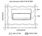
- the rectangular region R11 in FIG. 15A represents a set of real world colors that are perceived subjectively by humans as skin color, a transfer function for SDR, and BT.
- This is a region including a set of skin colors after mapping as a result of mapping on the Cb-Cr plane in the 709 color gamut.
- the left side and the right side of the rectangular region R11 correspond to threshold values that are compared with the code value of the Cb component when classifying whether the pixel belongs to the skin color region, and the lower side and the upper side indicate whether the pixel belongs to the skin color region.
- the same skin color set in the real world is transferred to the SDR transfer function and BT.
- mapping is performed on the Cb—Cr plane in the 2020 color gamut
- the set of these skin colors after mapping is located in the rectangular region R12.
- R11 and R12 are compared, in the case of SDR, when different types of color gamuts are applied to the image, different threshold values are used in the pixel classification process for classifying pixels as skin colors or not. It is understood that it should be.
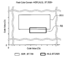
- the rectangular region R2 in FIG. 15B represents a set of the same skin color in the real world as S-Log3 and BT. This is a region including a set of skin colors after mapping as a result of mapping on the Cb—Cr plane in the 2020 color gamut.
- a rectangular region R3 in FIG. 15C represents a set of the same skin color in the real world as HLG and BT. This is a region including a set of skin colors after mapping as a result of mapping on the Cb—Cr plane in the 2020 color gamut.
- the rectangular area R3 occupies an area different from the rectangular area R2 on the Cb-Cr plane. This means that when a different transfer function is applied to an image even if the color gamut is the same, different threshold values should be used in the pixel classification process for classifying the pixel as skin color. I mean.
- the rectangular region R4 in FIG. 15D shows the result of mapping the same set of skin colors in the real world on the Cb-Cr plane as a result of mapping the HDR transfer functions S-Log3 and S-Gamut on the Cb-Cr plane. It is an area including a set of skin colors.
- the rectangular area R4 occupies an area different from the rectangular area R2 on the Cb-Cr plane. This is because, in the case of HDR, when different color gamuts are applied to an image even if the transfer function is the same, different threshold values are used in the pixel classification process for classifying pixels as skin colors. It means that it should be.
- the image processing system according to the present embodiment may be configured similarly to the image processing system 10a or 10b according to the first embodiment.
- any device in the system has a function as an encoder that encodes an image, and an area detection process is executed in the encoder to enhance protection of image quality of a specific area (for example, a skin color area). May be.
- the image processing system according to the present embodiment includes any type of device that acquires an image signal, in which pixels are used for various purposes such as face recognition, gesture recognition, biometric authentication, or augmented reality.
- a classification process may be performed.
- processing parameters for pixel classification are controlled based on at least one of a transfer function and a color gamut in such pixel classification processing. Thereby, it is possible to obtain a more accurate pixel classification result as compared with an example in which uniform processing parameters are used.
- FIG. 16 is a block diagram illustrating an example of a schematic configuration of an image processing apparatus according to the second embodiment.
- the image processing apparatus 200a illustrated in FIG. 16 includes a signal acquisition unit 201, an information acquisition unit 203, an encoding unit 210, and a control unit 240.
- the signal acquisition unit 201 acquires an input image signal generated based on a transfer function related to conversion between light and an image signal.
- the signal acquisition unit 201 may acquire an input image signal from an external device via a transmission interface, or input from an imaging module and a signal processing module (not shown) configured integrally with the image processing device 200a. An image signal may be acquired.
- the information acquisition unit 203 acquires input information related to the transfer function and color gamut applied to the image input to the encoding unit 210.
- the information acquisition unit 203 may acquire input information via a user interface included in the image processing apparatus 200a.
- the user interface may be provided by a physical input device such as a touch panel, a button, or a switch provided in the casing of the image processing apparatus 200a.
- the user interface may be provided as a GUI on a terminal device that is remotely connected via a communication interface.
- the input information includes at least a transfer function type indicating the type of transfer function applied to the image to be encoded and a color gamut type indicating the type of color gamut applied to the image.
- the user interface is, for example, BT.
- the user may select one of a plurality of transfer function type candidates that may include HLG, ST2084, and S-Log3 for HDR.
- the user interface is BT. 709, BT.
- the user may select one of a plurality of color gamut type candidates that may include 2020 and S-Gamut.
- the information acquisition unit 203 may acquire input information from an auxiliary signal multiplexed with an input image signal.
- the auxiliary signal is received by the signal acquisition unit 201 during a period in which no image signal is transmitted on the signal line.
- the information acquisition unit 203 can acquire input information including the transfer function type and the color gamut type from the auxiliary signal separated in the signal acquisition unit 201.
- the encoding unit 210 encodes an image represented by the image signal acquired by the signal acquisition unit 201 to generate an encoded bitstream.
- the encoding unit 210 is, for example, MPEG-2, H.264 or the like. H.264 / AVC or H.264
- the encoding process may be executed according to any video encoding method such as H.265 / HEVC.
- the encoding process executed by the encoding unit 210 includes a quantization process including irreversible compression for achieving a required compression rate.
- the control unit 240 performs pixel classification processing based on at least one of the transfer function type and the color gamut type indicated by the input information acquired by the information acquisition unit 203, and depends on the result of pixel classification, the encoding unit 210. Controls the quantization process in. For example, the control unit 240 detects a specific region in the image using different thresholds depending on what transfer function and color gamut combination is applied to the image. And the control part 240 strengthens the protection of the image quality of a specific area by scaling the quantization step applied to the detected specific area.
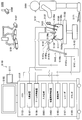
- FIG. 17 is a block diagram illustrating an example of a detailed configuration of the encoding unit and the control unit according to the second embodiment.
- the encoding unit 210 includes a rearrangement buffer 111, a block setting unit 112, a subtraction unit 113, an orthogonal transformation unit 114, a quantization unit 215, a lossless encoding unit 116, and an inverse quantum.
- the quantization unit 215 quantizes the transform coefficient data input from the orthogonal transform unit 114. More specifically, the quantization unit 215 tentatively determines a quantization step for each block so that a required compression rate is achieved, and further adjusts the quantization step according to the result of pixel classification. Then, the quantization unit 215 quantizes the transform coefficient data in the adjusted quantization step, and outputs the quantized data to the lossless encoding unit 116 and the inverse quantization unit 221.
- the adjustment of the quantization step in the quantization unit 215 may be performed by applying the adjustment gain provided by the control unit 240 to the provisional quantization step (for example, multiplying the provisional quantization step by the adjustment coefficient). As the adjustment gain increases, the quantization step is adjusted to a smaller value, and as a result, the allocation of the code amount to the target block increases. For example, by increasing the code amount allocation for the blocks belonging to the skin color region, the image quality protection of the region in which a human face or hand is shown can be enhanced.
- the quantization unit 215 may use a different quantization step for each color component.
- the inverse quantization unit 221 dequantizes the quantized data in the same quantization step as that used by the quantization unit 215, and restores transform coefficient data. Then, the inverse quantization unit 221 outputs the restored transform coefficient data to the inverse orthogonal transform unit 122.
- control unit 240 includes a threshold control unit 241, a pixel classification unit 243, and a quantization control unit 245.
- the threshold control unit 241 determines the transfer function and color gamut applied to the image to be encoded based on the input information input from the information acquisition unit 203. Then, the threshold control unit 241 determines a threshold to be used in the pixel classification process and to be compared with the code value of the color component based on the transfer function, the color gamut, or a combination thereof.
- the pixel classification process may be an area detection process for classifying whether each pixel represents a specific color and detecting a specific color area.
- the pixel classification process may be an area detection process for classifying whether each pixel represents a specific brightness and detecting a specific brightness area. It is not limited to these examples, Arbitrary pixel classification processing which classifies a pixel into a certain category may be adopted.
- the threshold control unit 241 uses, for example, a threshold associated with a type indicated by input information with reference to a memory (not shown) that stores a threshold associated with a transfer function or a color gamut, or a combination thereof. You may determine as a threshold value which should be. Typically, for each transfer function, for each color gamut, or for each of them, so as to negate the effect of the change in the code value of the image signal due to the difference between at least one of the transfer function and the color gamut on the pixel classification process Different thresholds may be used for each combination.
- the pixel classification unit 243 uses the threshold determined by the threshold control unit 241 to perform pixel classification processing on the image represented by the input image signal.
- the threshold value determined by the threshold control unit 241 includes a skin color determination threshold value.
- the skin color determination threshold corresponds to the boundary of the rectangular region R11, R12, R2, R3, or R4 illustrated in FIGS. 15A to 15D, the left side and the right side are two thresholds compared with the Cb component, and the lower side and the upper side are Cr. Each corresponds to two thresholds to be compared with the component. For example, a transfer function for SDR and BT.
- the pixel classification unit 243 indicates that the pixel represents the skin color when it is determined that each pixel is located in the rectangular region R11 on the Cb-Cr plane as a result of the threshold determination. Can be determined. SDR transfer function and BT. In the case where the color gamut of 2020 is applied, the pixel classification unit 243 represents the skin color when the pixel is determined to be located in the rectangular region R12 on the Cb-Cr plane as a result of the threshold determination. Can be determined. Even in cases where other transfer functions and color gamuts are applied, the same determination can be made using the corresponding region detection threshold. The pixel classification unit 243 outputs the result of such pixel classification to the quantization control unit 245.
- category method is not limited to this example.
- an area determination function that uses a code value of one or more color components as an argument may be used.
- a parameter such as a coefficient or a constant included in the area determination function may be switched depending on one or both of the transfer function and the color gamut.
- a plurality of area determination functions to which different identification information is assigned are defined in advance, and the area determination is identified by identification information selected depending on one or both of a transfer function and a color gamut.
- a function may be used.
- the quantization control unit 245 controls the quantization process executed in the quantization unit 215 based on the pixel classification result input from the pixel classification unit 243. For example, when the pixel or block to be controlled is classified as belonging to a specific region where it is desired to enhance the image quality protection, the quantization control unit 245 performs the provisional quantization step on the pixel or block. Alternatively, the quantization unit 215 may use a quantization step adjusted to a smaller value. In addition, the quantization control unit 245 causes the quantization unit 215 to use a quantization step adjusted to a value larger than the provisional quantization step for pixels or blocks belonging to an area where a certain degree of image quality degradation is allowed. Also good. As described above, the quantization unit 215 performs the quantization process in the quantization step adjusted based on the result of the pixel classification performed using the processing parameters that are flexibly set, thereby expressing the image signal. Consistent image quality protection that is not affected by
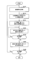
- FIG. 18 is a flowchart illustrating an example of the flow of the encoding control process according to the present embodiment.
- the encoding control process described here may be repeated for each image constituting the video. Processing steps for obtaining or setting parameters that do not change across multiple images may be skipped in the second and subsequent iterations.
- description of processing steps not related to pixel classification is omitted.
- the signal acquisition unit 201 acquires an image signal generated based on a transfer function relating to conversion between light and an image signal (step S210).
- the image signal acquired here is output to the encoding unit 210.
- the information acquisition unit 203 inputs the input information indicating the transfer function and the color gamut applied to the image input to the encoding unit 210 via the user interface or an auxiliary signal that is multiplexed with the input image signal. (Step S212).
- the input information acquired here is output to the control unit 240.
- the threshold control unit 241 determines a threshold for pixel classification based on at least one of the transfer function and the color gamut indicated by the input information described above (step S214).
- a block to be processed in each iteration is referred to as a target block here.
- the pixel classification unit 243 performs pixel classification for the block of interest using the threshold value determined by the threshold value control unit 241 (step S220). For example, in the case of specific area detection, the pixel classification unit 243 classifies whether each pixel in the block is located in a specific area surrounded by a threshold on the Cb-Cr plane. The pixel classification unit 243 calculates the ratio of the number of pixels located in the specific area to the total number of pixels in the block. Then, the pixel classification unit 243 can determine that the block of interest belongs to the specific region when the calculated ratio exceeds a predetermined threshold.
- the quantization unit 215 determines the provisional quantization step of the block of interest so that the required compression rate is achieved regardless of what transfer function and color gamut are applied (step S230). Next, the quantization unit 215 adjusts the quantization step determined in step S230 by using the adjustment coefficient determined by the quantization control unit 245 based on the pixel classification result (step S240). Then, the quantization unit 215 quantizes the transform coefficient data of the target block input from the orthogonal transform unit 214 in the adjusted quantization step (step S250).
- the lossless encoding unit 216 encodes the quantized data and the quantization parameter input from the quantization unit 215 to generate an encoded bit stream (step S260).
- Step S220 to step S260 are repeated until the processing is completed for all the blocks in the picture (step S280).
- the encoding control process shown in FIG. 18 ends (step S290).
- FIG. 19 is a block diagram showing a modification of the configuration of the image processing device according to the second embodiment.
- the image processing apparatus 200b illustrated in FIG. 19 includes a signal acquisition unit 201, an information acquisition unit 203, a threshold control unit 250, a pixel classification unit 260, and an output signal generation unit 270.
- the threshold control unit 250 determines the transfer function and color gamut applied to the image based on the input information input from the information acquisition unit 203. Then, the threshold control unit 250 determines a threshold to be used in the pixel classification process and to be compared with the code value of the color component based on the transfer function, the color gamut, or a combination thereof.
- the threshold control unit 250 uses, for example, a threshold associated with the type indicated by the input information with reference to a memory (not shown) that stores a threshold associated with a transfer function or a color gamut, or a combination thereof. You may determine as a threshold value which should be.
- the threshold control unit 250 outputs the determined threshold value to the pixel classification unit 260.
- the pixel classification unit 260 uses the threshold determined by the threshold control unit 250 to perform pixel classification processing on the image represented by the input image signal.
- the threshold value determined by the threshold control unit 250 includes a skin color determination threshold value.
- a transfer function for SDR and BT In the case where the color gamut of 709 is applied, the pixel classification unit 260 represents the skin color when it is determined that each pixel is located in the rectangular region R11 on the Cb-Cr plane as a result of the threshold determination. Can be determined. SDR transfer function and BT.
- the pixel classification unit 260 represents the skin color when the pixel is determined to be located in the rectangular region R12 on the Cb-Cr plane as a result of the threshold determination. Can be determined. Even in cases where other transfer functions and color gamuts are applied, the same determination can be performed using the corresponding skin color determination threshold.
- the pixel classification unit 260 outputs the result of such pixel classification to the output signal generation unit 270.
- the output signal generation unit 270 generates an output signal based on the pixel classification result input from the pixel classification unit 260. For example, the output signal generation unit 270 may generate an output signal for displaying a sign (for example, a frame surrounding the region) indicating the position of a specific region detected as a result of pixel classification on the image. Further, the output signal generation unit 270 may perform face recognition using the skin color area detection result and generate an output signal indicating the face recognition result. The output signal generation unit 270 may generate an output signal for displaying a result of gesture recognition, a result of biometric authentication, or a display object to be superimposed on an output image in augmented reality.
- a sign for example, a frame surrounding the region
- the output signal generation unit 270 may perform face recognition using the skin color area detection result and generate an output signal indicating the face recognition result.
- the output signal generation unit 270 may generate an output signal for displaying a result of gesture recognition, a result of biometric authentication, or a display object to be superimposed on an output
- FIG. 20 is a flowchart illustrating an example of the flow of image processing according to the modification described with reference to FIG.
- the signal acquisition unit 201 acquires an image signal generated based on a transfer function related to conversion between light and an image signal (step S210).
- the image signal acquired here is output to the pixel classification unit 260.
- the information acquisition unit 203 obtains input information indicating the transfer function and color gamut applied to the image processed by the pixel classification unit 260 from the auxiliary signal multiplexed with the input image signal through the user interface. Obtain (step S212). The input information acquired here is output to the threshold control unit 250.
- the threshold control unit 250 determines a threshold for pixel classification based on at least one of the transfer function and the color gamut indicated by the input information described above (step S214).
- the pixel classification unit 260 executes pixel classification for each pixel in the image using the threshold value determined by the threshold value control unit 250 (step S225). The pixel classification is repeated until there are no more pixels to be processed in the image (step S270).
- the output signal generation unit 270 generates an output signal based on the result of the pixel classification executed in step S225 (step S285).
- step S290 If there is no next image, the encoding control process shown in FIG. 20 ends.
- processing parameters relating to pixel classification processing that can be performed for various purposes are determined based on at least one of a transfer function and a color gamut relating to conversion between light and an image signal. According to such a configuration, it is possible to prevent a pixel from being classified based on an inappropriate reference due to a difference in transfer function or a color gamut, and to ensure proper execution of processing based on the result of pixel classification. Can do.
- the threshold value to be compared with the code value of the color component in the pixel classification process is determined based on at least one of the transfer function and the color gamut. According to such a configuration, even when the same brightness or color in the real world is expressed by different code values depending on the selection of the transfer function or the color gamut, a consistent threshold value that is not affected by the representation method of the image signals. A decision can be provided.
- the pixel classification process may be an area detection process for detecting a specific area in the image
- the threshold value may be an area detection threshold value.
- a quantization process at the time of encoding an image is executed in a quantization step adjusted based on the result of the region detection process described above. In this case, it is possible to accurately detect a specific area where it is desired to enhance the protection of image quality, and to increase the amount of code assigned to the specific area.
- the transfer function and the color gamut can be determined based on the input information related to the transfer function and the color gamut.
- control as desired by the user can be executed even when the transfer function or color gamut cannot be determined from the input signal.
- the input information is acquired from an auxiliary signal multiplexed with an input image signal, an appropriate type can be automatically determined without requiring user input.
- Hardware configuration example> The embodiments described up to the previous section may be implemented using any of software, hardware, and a combination of software and hardware.
- a program that configures the software is stored in advance in, for example, a storage medium (non-transitory media) provided inside or outside the apparatus. Stored.
- Each program is read into a RAM (Random Access Memory) at the time of execution and executed by a processor such as a CPU (Central Processing Unit).
- RAM Random Access Memory
- FIG. 21 is a block diagram illustrating an example of a hardware configuration of an apparatus to which one or more of the above-described embodiments can be applied.
- the image processing apparatus 900 includes a system bus 910, an image processing chip 920, and an off-chip memory 990.
- the image processing chip 920 includes n (n is 1 or more) processing circuits 930-1, 930-2,..., 930-n, a reference buffer 940, a system bus interface 950, and a local bus interface 960.
- the system bus 910 provides a communication path between the image processing chip 920 and an external module (for example, a central control function, an application function, a communication interface, or a user interface).
- the processing circuits 930-1, 930-2,..., 930-n are connected to the system bus 910 via the system bus interface 950 and to the off-chip memory 990 via the local bus interface 960.
- the processing circuits 930-1, 930-2,..., 930-n can also access a reference buffer 940, which can correspond to an on-chip memory (eg, SRAM).
- the off-chip memory 990 may be a frame memory that stores image data processed by the image processing chip 920, for example.
- the processing circuit 930-1 may be used for conversion of an image signal.
- the processing circuit 930-2 may be used for encoding an image signal.
- Other processing circuits may be used for pixel classification. Note that these processing circuits may be formed not on the same image processing chip 920 but on separate chips.
- the technology according to the present disclosure can be applied to various products.
- the technology according to the present disclosure may be applied to an operating room system as described in this section.
- FIG. 22 is a diagram schematically showing an overall configuration of an operating room system 5100 to which the technology according to the present disclosure can be applied.
- the operating room system 5100 is configured by connecting a group of devices installed in the operating room so as to cooperate with each other via an audio-visual controller (AV Controller) 5107 and an operating room control device 5109.
- AV Controller audio-visual controller
- FIG. 22 various devices can be installed in the operating room.
- various apparatus groups 5101 for endoscopic surgery a ceiling camera 5187 provided on the ceiling of the operating room and imaging the operator's hand, and an operating room provided on the operating room ceiling.
- An operating field camera 5189 that images the entire situation, a plurality of display devices 5103A to 5103D, a recorder 5105, a patient bed 5183, and an illumination 5191 are illustrated.
- the device group 5101 belongs to an endoscopic surgery system 5113 described later, and includes an endoscope, a display device that displays an image captured by the endoscope, and the like.
- Each device belonging to the endoscopic surgery system 5113 is also referred to as a medical device.
- the display devices 5103A to 5103D, the recorder 5105, the patient bed 5183, and the illumination 5191 are devices provided in an operating room, for example, separately from the endoscopic surgery system 5113.
- These devices that do not belong to the endoscopic surgery system 5113 are also referred to as non-medical devices.
- the audiovisual controller 5107 and / or the operating room control device 5109 controls the operations of these medical devices and non-medical devices in cooperation with each other.
- the audiovisual controller 5107 comprehensively controls processing related to image display in medical devices and non-medical devices.
- the device group 5101, the ceiling camera 5187, and the surgical field camera 5189 have a function of transmitting information to be displayed during surgery (hereinafter also referred to as display information). It may be a device (hereinafter also referred to as a source device).
- Display devices 5103A to 5103D can be devices that output display information (hereinafter also referred to as output destination devices).
- the recorder 5105 may be a device that corresponds to both a transmission source device and an output destination device.
- the audiovisual controller 5107 controls the operation of the transmission source device and the output destination device, acquires display information from the transmission source device, and transmits the display information to the output destination device for display or recording.
- the display information includes various images captured during the operation, various types of information related to the operation (for example, patient physical information, past examination results, information on a surgical procedure, and the like).
- the audiovisual controller 5107 can transmit information about the image of the surgical site in the patient's body cavity captured by the endoscope from the device group 5101 as display information.
- information about the image at hand of the surgeon captured by the ceiling camera 5187 can be transmitted from the ceiling camera 5187 as display information.
- information about an image showing the entire operating room imaged by the operating field camera 5189 can be transmitted from the operating field camera 5189 as display information.
- the audiovisual controller 5107 acquires information about an image captured by the other device from the other device as display information. May be.
- information about these images captured in the past is recorded by the audiovisual controller 5107 in the recorder 5105.
- the audiovisual controller 5107 can acquire information about the image captured in the past from the recorder 5105 as display information.
- the recorder 5105 may also record various types of information related to surgery in advance.
- the audiovisual controller 5107 displays the acquired display information (that is, images taken during the operation and various information related to the operation) on at least one of the display devices 5103A to 5103D that are output destination devices.
- the display device 5103A is a display device that is suspended from the ceiling of the operating room
- the display device 5103B is a display device that is installed on the wall surface of the operating room
- the display device 5103C is installed in the operating room.
- the display device 5103D is a mobile device (for example, a tablet PC (Personal Computer)) having a display function.
- the operating room system 5100 may include a device outside the operating room.
- the device outside the operating room can be, for example, a server connected to a network constructed inside or outside the hospital, a PC used by medical staff, a projector installed in a conference room of the hospital, or the like.
- the audio-visual controller 5107 can display the display information on a display device of another hospital via a video conference system or the like for telemedicine.
- the operating room control device 5109 comprehensively controls processing other than processing related to image display in non-medical devices.
- the operating room control device 5109 controls the driving of the patient bed 5183, the ceiling camera 5187, the operating field camera 5189, and the illumination 5191.
- the operating room system 5100 is provided with a centralized operation panel 5111, and the user gives an instruction for image display to the audiovisual controller 5107 via the centralized operation panel 5111, or the operating room control apparatus 5109. An instruction about the operation of the non-medical device can be given.
- the central operation panel 5111 is configured by providing a touch panel on the display surface of the display device.
- FIG. 23 is a diagram showing a display example of an operation screen on the centralized operation panel 5111.
- an operation screen corresponding to a case where the operating room system 5100 is provided with two display devices as output destination devices is shown.
- the operation screen 5193 is provided with a transmission source selection area 5195, a preview area 5197, and a control area 5201.
- a transmission source device provided in the operating room system 5100 and a thumbnail screen representing display information of the transmission source device are displayed in association with each other. The user can select display information to be displayed on the display device from any of the transmission source devices displayed in the transmission source selection area 5195.
- the preview area 5197 displays a preview of the screen displayed on the two display devices (Monitor 1 and Monitor 2) that are output destination devices.
- four images are displayed as PinP on one display device.
- the four images correspond to display information transmitted from the transmission source device selected in the transmission source selection area 5195. Of the four images, one is displayed as a relatively large main image, and the remaining three are displayed as a relatively small sub image. The user can switch the main image and the sub image by appropriately selecting an area in which four images are displayed.
- a status display area 5199 is provided below the area where the four images are displayed, and the status relating to the surgery (for example, the elapsed time of the surgery, the patient's physical information, etc.) is appropriately displayed in the area. obtain.
- a GUI (Graphical User Interface) part for displaying a GUI (Graphical User Interface) part for operating the source apparatus and a GUI part for operating the output destination apparatus are displayed.
- the transmission source operation area 5203 is provided with GUI parts for performing various operations (panning, tilting, and zooming) on the camera in the transmission source device having an imaging function. The user can operate the operation of the camera in the transmission source device by appropriately selecting these GUI components.
- the transmission source device selected in the transmission source selection area 5195 is a recorder (that is, in the preview area 5197, images recorded in the past are displayed on the recorder).
- a GUI component for performing operations such as playback, stop playback, rewind, and fast forward of the image can be provided in the transmission source operation area 5203.
- GUI parts for performing various operations are provided. Is provided. The user can operate the display on the display device by appropriately selecting these GUI components.
- the operation screen displayed on the centralized operation panel 5111 is not limited to the example shown in the figure, and the user can use the audiovisual controller 5107 and the operating room control device 5109 provided in the operating room system 5100 via the centralized operation panel 5111. Operation input for each device that can be controlled may be possible.
- FIG. 24 is a diagram showing an example of a state of surgery to which the operating room system described above is applied.
- the ceiling camera 5187 and the operating field camera 5189 are provided on the ceiling of the operating room, and can photograph the state of the operator (doctor) 5181 who performs treatment on the affected part of the patient 5185 on the patient bed 5183 and the entire operating room. It is.
- the ceiling camera 5187 and the surgical field camera 5189 may be provided with a magnification adjustment function, a focal length adjustment function, a photographing direction adjustment function, and the like.
- the illumination 5191 is provided on the ceiling of the operating room and irradiates at least the hand of the operator 5181.
- the illumination 5191 may be capable of appropriately adjusting the irradiation light amount, the wavelength (color) of the irradiation light, the light irradiation direction, and the like.
- Endoscopic surgery system 5113, patient bed 5183, ceiling camera 5187, operating field camera 5189, and illumination 5191 are connected via audiovisual controller 5107 and operating room controller 5109 (not shown in FIG. 24) as shown in FIG. Are connected to each other.
- a centralized operation panel 5111 is provided in the operating room. As described above, the user can appropriately operate these devices existing in the operating room via the centralized operating panel 5111.
- an endoscopic surgery system 5113 includes an endoscope 5115, other surgical tools 5131, a support arm device 5141 that supports the endoscope 5115, and various devices for endoscopic surgery. And a cart 5151 on which is mounted.
- trocars 5139a to 5139d are punctured into the abdominal wall. Then, the lens barrel 5117 of the endoscope 5115 and other surgical tools 5131 are inserted into the body cavity of the patient 5185 from the trocars 5139a to 5139d.
- an insufflation tube 5133, an energy treatment tool 5135, and forceps 5137 are inserted into the body cavity of the patient 5185.
- the energy treatment instrument 5135 is a treatment instrument that performs incision and detachment of a tissue, blood vessel sealing, and the like by a high-frequency current and ultrasonic vibration.
- the illustrated surgical tool 5131 is merely an example, and as the surgical tool 5131, for example, various surgical tools generally used in endoscopic surgery such as a lever and a retractor may be used.
- An image of the surgical site in the body cavity of the patient 5185 taken by the endoscope 5115 is displayed on the display device 5155.
- the surgeon 5181 performs a treatment such as excision of the affected part using the energy treatment tool 5135 and the forceps 5137 while viewing the image of the surgical part displayed on the display device 5155 in real time.
- the pneumoperitoneum tube 5133, the energy treatment tool 5135, and the forceps 5137 are supported by an operator 5181 or an assistant during surgery.
- the support arm device 5141 includes an arm portion 5145 extending from the base portion 5143.
- the arm portion 5145 includes joint portions 5147a, 5147b, and 5147c, and links 5149a and 5149b, and is driven by control from the arm control device 5159.
- the endoscope 5115 is supported by the arm unit 5145, and its position and posture are controlled. Thereby, the stable position fixing of the endoscope 5115 can be realized.
- the endoscope 5115 includes a lens barrel 5117 in which a region having a predetermined length from the distal end is inserted into the body cavity of the patient 5185, and a camera head 5119 connected to the proximal end of the lens barrel 5117.
- an endoscope 5115 configured as a so-called rigid mirror having a rigid lens barrel 5117 is illustrated, but the endoscope 5115 is configured as a so-called flexible mirror having a flexible lens barrel 5117. Also good.
- An opening into which an objective lens is fitted is provided at the tip of the lens barrel 5117.
- a light source device 5157 is connected to the endoscope 5115, and the light generated by the light source device 5157 is guided to the tip of the lens barrel by a light guide extending inside the lens barrel 5117, and the objective Irradiation is performed toward the observation target in the body cavity of the patient 5185 through the lens.
- the endoscope 5115 may be a direct endoscope, a perspective mirror, or a side endoscope.
- An optical system and an image sensor are provided inside the camera head 5119, and reflected light (observation light) from the observation target is condensed on the image sensor by the optical system. Observation light is photoelectrically converted by the imaging element, and an electrical signal corresponding to the observation light, that is, an image signal corresponding to the observation image is generated.
- the image signal is transmitted to a camera control unit (CCU) 5153 as RAW data.
- CCU camera control unit
- the camera head 5119 has a function of adjusting the magnification and the focal length by appropriately driving the optical system.
- a plurality of image sensors may be provided in the camera head 5119 in order to cope with, for example, stereoscopic viewing (3D display).
- a plurality of relay optical systems are provided inside the lens barrel 5117 in order to guide observation light to each of the plurality of imaging elements.
- the CCU 5153 includes a CPU (Central Processing Unit), a GPU (Graphics Processing Unit), and the like, and comprehensively controls the operations of the endoscope 5115 and the display device 5155. Specifically, the CCU 5153 performs various image processing for displaying an image based on the image signal, such as development processing (demosaic processing), for example, on the image signal received from the camera head 5119. The CCU 5153 provides the display device 5155 with the image signal subjected to the image processing. Further, the audiovisual controller 5107 shown in FIG. 22 is connected to the CCU 5153. The CCU 5153 also provides an image signal subjected to image processing to the audiovisual controller 5107.
- a CPU Central Processing Unit
- GPU Graphics Processing Unit
- the CCU 5153 transmits a control signal to the camera head 5119 to control the driving thereof.
- the control signal can include information regarding imaging conditions such as magnification and focal length. Information regarding the imaging conditions may be input via the input device 5161 or may be input via the above-described centralized operation panel 5111.
- the display device 5155 displays an image based on an image signal subjected to image processing by the CCU 5153 under the control of the CCU 5153.
- the endoscope 5115 is compatible with high-resolution imaging such as 4K (horizontal pixel number 3840 ⁇ vertical pixel number 2160) or 8K (horizontal pixel number 7680 ⁇ vertical pixel number 4320), and / or 3D display.
- high-resolution imaging such as 4K (horizontal pixel number 3840 ⁇ vertical pixel number 2160) or 8K (horizontal pixel number 7680 ⁇ vertical pixel number 4320), and / or 3D display.
- a display device 5155 capable of high-resolution display and / or 3D display can be used.
- 4K or 8K high resolution imaging a more immersive feeling can be obtained by using a display device 5155 having a size of 55 inches or more.
- a plurality of display devices 5155 having different resolutions and sizes may be provided depending on applications.
- the light source device 5157 is composed of a light source such as an LED (light emitting diode), for example, and supplies the endoscope 5115 with irradiation light when photographing a surgical site.
- a light source such as an LED (light emitting diode)
- the arm control device 5159 is configured by a processor such as a CPU, for example, and operates according to a predetermined program to control driving of the arm portion 5145 of the support arm device 5141 according to a predetermined control method.
- the input device 5161 is an input interface to the endoscopic surgery system 5113.
- a user can input various information and instructions to the endoscopic surgery system 5113 via the input device 5161.
- the user inputs various types of information related to the operation, such as the patient's physical information and information about the surgical technique, via the input device 5161.
- the user instructs to drive the arm unit 5145 via the input device 5161 or an instruction to change the imaging conditions (type of irradiation light, magnification, focal length, etc.) by the endoscope 5115.
- An instruction to drive the energy treatment instrument 5135 is input.
- the type of the input device 5161 is not limited, and the input device 5161 may be various known input devices.
- the input device 5161 for example, a mouse, a keyboard, a touch panel, a switch, a foot switch 5171 and / or a lever can be applied.
- the touch panel may be provided on the display surface of the display device 5155.
- the input device 5161 is a device worn by the user, such as a glasses-type wearable device or an HMD (Head Mounted Display), for example, and various inputs according to the user's gesture and line of sight detected by these devices. Is done.
- the input device 5161 includes a camera capable of detecting a user's movement, and various inputs are performed according to a user's gesture and line of sight detected from an image captured by the camera.
- the input device 5161 includes a microphone that can pick up the voice of the user, and various inputs are performed by voice through the microphone.
- the input device 5161 is configured to be able to input various types of information without contact, so that a user belonging to the clean area (for example, an operator 5181) operates a device belonging to the unclean area without contact. Is possible.
- a user belonging to the clean area for example, an operator 5181
- the user can operate the device without releasing his / her hand from the surgical tool he / she has, the convenience for the user is improved.
- the treatment instrument control device 5163 controls driving of the energy treatment instrument 5135 for tissue cauterization, incision, blood vessel sealing, or the like.
- the pneumoperitoneum device 5165 passes gas into the body cavity via the pneumothorax tube 5133.
- the recorder 5167 is an apparatus capable of recording various types of information related to surgery.
- the printer 5169 is a device that can print various types of information related to surgery in various formats such as text, images, or graphs.
- the support arm device 5141 includes a base portion 5143 which is a base, and an arm portion 5145 extending from the base portion 5143.
- the arm portion 5145 includes a plurality of joint portions 5147a, 5147b, and 5147c and a plurality of links 5149a and 5149b connected by the joint portions 5147b.
- FIG. The structure of the arm part 5145 is shown in a simplified manner. Actually, the shape, number and arrangement of the joint portions 5147a to 5147c and the links 5149a and 5149b, the direction of the rotation axis of the joint portions 5147a to 5147c, and the like are appropriately set so that the arm portion 5145 has a desired degree of freedom. obtain.
- the arm portion 5145 can be preferably configured to have six or more degrees of freedom. Accordingly, the endoscope 5115 can be freely moved within the movable range of the arm unit 5145, and therefore the lens barrel 5117 of the endoscope 5115 can be inserted into the body cavity of the patient 5185 from a desired direction. It becomes possible.
- the joint portions 5147a to 5147c are provided with actuators, and the joint portions 5147a to 5147c are configured to be rotatable around a predetermined rotation axis by driving the actuators.
- the drive of the actuator is controlled by the arm control device 5159
- the rotation angles of the joint portions 5147a to 5147c are controlled, and the drive of the arm portion 5145 is controlled.
- control of the position and posture of the endoscope 5115 can be realized.
- the arm control device 5159 can control the driving of the arm unit 5145 by various known control methods such as force control or position control.
- the arm controller 5159 appropriately controls the driving of the arm unit 5145 according to the operation input.
- the position and posture of the endoscope 5115 may be controlled. With this control, the endoscope 5115 at the distal end of the arm portion 5145 can be moved from an arbitrary position to an arbitrary position and then fixedly supported at the position after the movement.
- the arm unit 5145 may be operated by a so-called master slave method. In this case, the arm unit 5145 can be remotely operated by the user via the input device 5161 installed at a location away from the operating room.
- the arm control device 5159 When force control is applied, the arm control device 5159 receives the external force from the user and moves the actuators of the joint portions 5147a to 5147c so that the arm portion 5145 moves smoothly according to the external force. You may perform what is called power assist control to drive. Accordingly, when the user moves the arm unit 5145 while directly touching the arm unit 5145, the arm unit 5145 can be moved with a relatively light force. Therefore, the endoscope 5115 can be moved more intuitively and with a simpler operation, and the convenience for the user can be improved.
- an endoscope 5115 is supported by a doctor called a scopist.
- the position of the endoscope 5115 can be more reliably fixed without relying on human hands, so that an image of the surgical site can be stably obtained. It becomes possible to perform the operation smoothly.
- the arm control device 5159 is not necessarily provided in the cart 5151. Further, the arm control device 5159 does not necessarily have to be one device. For example, the arm control device 5159 may be provided in each of the joint portions 5147a to 5147c of the arm portion 5145 of the support arm device 5141, and the plurality of arm control devices 5159 cooperate to drive the arm portion 5145. Control may be realized.
- the light source device 5157 supplies irradiation light for imaging the surgical site to the endoscope 5115.
- the light source device 5157 is constituted by a white light source constituted by, for example, an LED, a laser light source or a combination thereof.
- a white light source is configured by a combination of RGB laser light sources
- the output intensity and output timing of each color (each wavelength) can be controlled with high accuracy. Adjustments can be made.
- the laser light from each of the RGB laser light sources is irradiated onto the observation target in a time-sharing manner, and the driving of the image sensor of the camera head 5119 is controlled in synchronization with the irradiation timing, thereby corresponding to each RGB. It is also possible to take the images that have been taken in time division. According to this method, a color image can be obtained without providing a color filter in the image sensor.
- the driving of the light source device 5157 may be controlled so as to change the intensity of the output light every predetermined time. Synchronously with the timing of changing the intensity of the light, the driving of the image sensor of the camera head 5119 is controlled to acquire an image in a time-sharing manner, and the image is synthesized, so that high dynamic without so-called blackout and overexposure is obtained. A range image can be generated.
- the light source device 5157 may be configured to be able to supply light of a predetermined wavelength band corresponding to special light observation.
- special light observation for example, by utilizing the wavelength dependence of light absorption in body tissue, the surface of the mucous membrane is irradiated by irradiating light in a narrow band compared to irradiation light (ie, white light) during normal observation.
- narrow band imaging is performed in which a predetermined tissue such as a blood vessel is imaged with high contrast.
- fluorescence observation may be performed in which an image is obtained by fluorescence generated by irradiating excitation light.
- the body tissue is irradiated with excitation light to observe fluorescence from the body tissue (autofluorescence observation), or a reagent such as indocyanine green (ICG) is locally administered to the body tissue and applied to the body tissue.
- a reagent such as indocyanine green (ICG) is locally administered to the body tissue and applied to the body tissue.
- ICG indocyanine green
- the light source device 5157 can be configured to be able to supply narrowband light and / or excitation light corresponding to such special light observation.
- FIG. 25 is a block diagram illustrating an example of functional configurations of the camera head 5119 and the CCU 5153 illustrated in FIG.
- the camera head 5119 has a lens unit 5121, an imaging unit 5123, a drive unit 5125, a communication unit 5127, and a camera head control unit 5129 as its functions.
- the CCU 5153 includes a communication unit 5173, an image processing unit 5175, and a control unit 5177 as its functions.
- the camera head 5119 and the CCU 5153 are connected to each other via a transmission cable 5179 so that they can communicate with each other.
- the lens unit 5121 is an optical system provided at a connection portion with the lens barrel 5117. Observation light taken from the tip of the lens barrel 5117 is guided to the camera head 5119 and enters the lens unit 5121.
- the lens unit 5121 is configured by combining a plurality of lenses including a zoom lens and a focus lens. The optical characteristics of the lens unit 5121 are adjusted so that the observation light is condensed on the light receiving surface of the image sensor of the imaging unit 5123. Further, the zoom lens and the focus lens are configured such that their positions on the optical axis are movable in order to adjust the magnification and focus of the captured image.
- the imaging unit 5123 is configured by an imaging element, and is arranged at the rear stage of the lens unit 5121.
- the observation light that has passed through the lens unit 5121 is collected on the light receiving surface of the imaging element, and an image signal corresponding to the observation image is generated by photoelectric conversion.
- the image signal generated by the imaging unit 5123 is provided to the communication unit 5127.
- the image pickup element constituting the image pickup unit 5123 for example, a CMOS (Complementary Metal Oxide Semiconductor) type image sensor that can perform color photographing having a Bayer array is used.
- the imaging element for example, an element capable of capturing a high-resolution image of 4K or more may be used.
- the image sensor that constitutes the image capturing unit 5123 is configured to have a pair of image sensors for acquiring right-eye and left-eye image signals corresponding to 3D display. By performing the 3D display, the operator 5181 can more accurately grasp the depth of the living tissue in the surgical site. Note that in the case where the imaging unit 5123 is configured as a multi-plate type, a plurality of lens units 5121 are also provided corresponding to each imaging element.
- the imaging unit 5123 is not necessarily provided in the camera head 5119.
- the imaging unit 5123 may be provided inside the lens barrel 5117 immediately after the objective lens.
- the driving unit 5125 includes an actuator, and moves the zoom lens and the focus lens of the lens unit 5121 by a predetermined distance along the optical axis under the control of the camera head control unit 5129. Thereby, the magnification and focus of the image captured by the imaging unit 5123 can be adjusted as appropriate.
- the communication unit 5127 includes a communication device for transmitting and receiving various types of information to and from the CCU 5153.
- the communication unit 5127 transmits the image signal obtained from the imaging unit 5123 to the CCU 5153 via the transmission cable 5179 as RAW data.
- the image signal is preferably transmitted by optical communication.
- the surgeon 5181 performs the surgery while observing the state of the affected part with the captured image, so that a moving image of the surgical part is displayed in real time as much as possible for safer and more reliable surgery. Because it is required.
- the communication unit 5127 is provided with a photoelectric conversion module that converts an electrical signal into an optical signal.
- the image signal is converted into an optical signal by the photoelectric conversion module, and then transmitted to the CCU 5153 via the transmission cable 5179.
- the communication unit 5127 receives a control signal for controlling the driving of the camera head 5119 from the CCU 5153.
- the control signal includes, for example, information for designating the frame rate of the captured image, information for designating the exposure value at the time of imaging, and / or information for designating the magnification and focus of the captured image. Contains information about the condition.
- the communication unit 5127 provides the received control signal to the camera head control unit 5129.
- the control signal from the CCU 5153 may also be transmitted by optical communication.
- the communication unit 5127 is provided with a photoelectric conversion module that converts an optical signal into an electrical signal.
- the control signal is converted into an electrical signal by the photoelectric conversion module and then provided to the camera head control unit 5129.
- the imaging conditions such as the frame rate, exposure value, magnification, and focus are automatically set by the control unit 5177 of the CCU 5153 based on the acquired image signal. That is, a so-called AE (Auto Exposure) function, AF (Auto Focus) function, and AWB (Auto White Balance) function are mounted on the endoscope 5115.
- AE Auto Exposure
- AF Automatic Focus
- AWB Automatic White Balance
- the camera head control unit 5129 controls driving of the camera head 5119 based on a control signal from the CCU 5153 received via the communication unit 5127. For example, the camera head control unit 5129 controls driving of the image sensor of the imaging unit 5123 based on information indicating that the frame rate of the captured image is specified and / or information indicating that the exposure at the time of imaging is specified. For example, the camera head control unit 5129 appropriately moves the zoom lens and the focus lens of the lens unit 5121 via the drive unit 5125 based on information indicating that the magnification and focus of the captured image are designated.
- the camera head control unit 5129 may further have a function of storing information for identifying the lens barrel 5117 and the camera head 5119.
- the camera head 5119 can be resistant to autoclave sterilization by arranging the lens unit 5121, the imaging unit 5123, and the like in a sealed structure with high airtightness and waterproofness.
- the communication unit 5173 is configured by a communication device for transmitting and receiving various types of information to and from the camera head 5119.
- the communication unit 5173 receives an image signal transmitted from the camera head 5119 via the transmission cable 5179.
- the image signal can be suitably transmitted by optical communication.
- the communication unit 5173 is provided with a photoelectric conversion module that converts an optical signal into an electric signal.
- the communication unit 5173 provides the image processing unit 5175 with the image signal converted into the electrical signal.
- the communication unit 5173 transmits a control signal for controlling the driving of the camera head 5119 to the camera head 5119.
- the control signal may also be transmitted by optical communication.
- the image processing unit 5175 performs various types of image processing on the image signal that is RAW data transmitted from the camera head 5119. Examples of the image processing include development processing, high image quality processing (band enhancement processing, super-resolution processing, NR (Noise reduction) processing and / or camera shake correction processing, etc.), and / or enlargement processing (electronic zoom processing). Various known signal processing is included. Further, the image processing unit 5175 performs detection processing on the image signal for performing AE, AF, and AWB.
- the image processing unit 5175 is configured by a processor such as a CPU or a GPU, and the above-described image processing and detection processing can be performed by the processor operating according to a predetermined program. Note that when the image processing unit 5175 includes a plurality of GPUs, the image processing unit 5175 appropriately divides information related to the image signal, and performs image processing in parallel with the plurality of GPUs.
- the control unit 5177 performs various controls relating to imaging of the surgical site by the endoscope 5115 and display of the captured image. For example, the control unit 5177 generates a control signal for controlling driving of the camera head 5119. At this time, when the imaging condition is input by the user, the control unit 5177 generates a control signal based on the input by the user. Alternatively, when the endoscope 5115 is equipped with the AE function, the AF function, and the AWB function, the control unit 5177 determines the optimum exposure value, focal length, and the distance according to the detection processing result by the image processing unit 5175. A white balance is appropriately calculated and a control signal is generated.
- control unit 5177 causes the display device 5155 to display an image of the surgical site based on the image signal subjected to image processing by the image processing unit 5175.
- the control unit 5177 recognizes various objects in the surgical unit image using various image recognition techniques. For example, the control unit 5177 detects the shape and color of the edge of the object included in the surgical part image, thereby removing surgical tools such as forceps, specific biological parts, bleeding, mist when using the energy treatment tool 5135, and the like. Can be recognized.
- the control unit 5177 causes various types of surgery support information to be superimposed and displayed on the image of the surgical site using the recognition result. Surgery support information is displayed in a superimposed manner and presented to the operator 5181, so that the surgery can be performed more safely and reliably.
- the transmission cable 5179 connecting the camera head 5119 and the CCU 5153 is an electric signal cable corresponding to electric signal communication, an optical fiber corresponding to optical communication, or a composite cable thereof.
- communication is performed by wire using the transmission cable 5179, but communication between the camera head 5119 and the CCU 5153 may be performed wirelessly.
- communication between the two is performed wirelessly, there is no need to install the transmission cable 5179 in the operating room, so that the situation where the movement of the medical staff in the operating room is hindered by the transmission cable 5179 can be solved.
- the operating room system 5100 to which the technology according to the present disclosure can be applied has been described.
- the medical system to which the operating room system 5100 is applied is the endoscopic operating system 5113 is described here as an example
- the configuration of the operating room system 5100 is not limited to such an example.
- the operating room system 5100 may be applied to an examination flexible endoscope system or a microscope operation system instead of the endoscope operation system 5113.
- the technology according to the present disclosure can be preferably applied to the recorder 5105 among the configurations described above.
- the recorder 5105 relates to a quantization process according to the technique according to the present disclosure when encoding an image captured by any camera (for example, the ceiling camera 5187, the surgical field camera 5189, or the camera head 5119).
- the processing parameter may be determined based on at least one of a transfer function and a color gamut for conversion between light and an image signal. Accordingly, it is possible to prevent an inappropriate quantization step from being used due to a difference in transfer function or color gamut, and to secure a sufficient allocated code amount for expressing the gradation of the original signal. .
- the processing parameters related to pixel classification processing that can be performed for various purposes according to the technique according to the present disclosure are set as light and image. You may determine based on at least one of the transfer function regarding the conversion between signals, and a color gamut. Accordingly, it is possible to prevent pixels from being classified based on an inappropriate standard due to a difference in transfer function or color gamut, and to ensure proper execution of processing based on the classification. As a result, in any example, the accuracy of diagnosis or treatment using images can be improved.
- the technology according to the present disclosure is not necessarily fully adapted to the diversified video signal representation according to the mechanism described in detail so far, for example, a digital video camera, a digital camcorder, a video encoder, or an encoding function or a pixel classification function. It provides an improvement over any kind of existing device that you have. According to the technology according to the present disclosure, it is possible to prevent inappropriate processing parameters from being used when handling HDR video.
- luminance / luma and chrominance / chroma are replaced by other terms such as brightness and saturation, depending on the color system used. May be.
- a control unit that determines processing parameters for image processing on the image based on at least one of a transfer function relating to conversion between light applied to the image and an image signal and a color gamut applied to the image
- a processing unit that executes the image processing using the processing parameter determined by the control unit
- An image processing apparatus comprising: (2) The image processing apparatus according to (1), wherein the control unit determines the processing parameter based on a combination of the transfer function and the color gamut.
- the control unit determines the processing parameter so as to cancel the influence of the change in the code value of the image signal due to the difference between the at least one of the transfer function and the color gamut on the image processing;
- the image processing apparatus according to (1) or (2).
- the processing unit performs a quantization process for each partial region in a quantization step adjusted according to the encoding difficulty level for each partial region of the image,
- the processing parameter is a parameter relating to the quantization processing.
- the image processing apparatus according to any one of (1) to (3).
- the parameter related to the quantization process includes an adjustment gain of the quantization step for the image.
- the control unit determines a basic adjustment gain of the quantization step for the image based on the at least one of the transfer function and the color gamut.
- the processing unit performs the quantization process on each partial region in the post-adjustment quantization step adjusted based on the basic adjustment gain and the encoding difficulty level of each partial region.
- the image processing apparatus described. (8) The image processing apparatus according to (1) or (2), wherein the processing unit performs pixel classification processing on the image using the processing parameter. (9) The image processing apparatus according to (8), wherein the processing parameter includes a threshold value to be compared with a code value of a color component in the pixel classification process. (10)
- the pixel classification process includes an area detection process for detecting a specific area in the image, The threshold value includes a region detection threshold value, The image processing apparatus according to (9).
- the specific area is an area of a specific color;
- the region detection threshold includes a color determination threshold,
- the specific color is a skin color;
- the color determination threshold includes a skin color determination threshold,
- the control unit determines the type of the at least one of the transfer function and the color gamut based on input information regarding the at least one of the transfer function and the color gamut, and based on the determined type
- the image processing apparatus according to any one of (1) to (14), wherein the processing parameter for the image processing is determined.
- the input information is information acquired through a user interface.
- the input information is information acquired from an auxiliary signal multiplexed with an input image signal representing the image.
- An image processing method including: (19) The processor of the image processing device, A control unit that determines processing parameters for image processing on the image based on at least one of a transfer function relating to conversion between light applied to the image and an image signal and a color gamut applied to the image When, A processing unit that executes the image processing using the processing parameter determined by the control unit; Program to function as.
- 100a, 100b Image processing apparatus 101 Signal acquisition unit 102 Signal processing unit 103, 104 Information acquisition unit 107 Storage unit 110 Coding unit 115 Quantization unit (processing unit) 140 Control Unit 200a, 200b Image Processing Device 201 Signal Acquisition Unit 203 Information Acquisition Unit 210 Encoding Unit 240 Control Unit 241, 250 Threshold Control Unit 243, 260 Pixel Classification Unit (Processing Unit) 270 Output signal generator
Landscapes
- Engineering & Computer Science (AREA)
- Multimedia (AREA)
- Signal Processing (AREA)
- Physics & Mathematics (AREA)
- General Physics & Mathematics (AREA)
- Theoretical Computer Science (AREA)
- Compression Or Coding Systems Of Tv Signals (AREA)
- Image Processing (AREA)
- Color Television Image Signal Generators (AREA)
- Facsimile Image Signal Circuits (AREA)
Priority Applications (6)
| Application Number | Priority Date | Filing Date | Title |
|---|---|---|---|
| KR1020197016706A KR20190097004A (ko) | 2016-12-19 | 2017-10-17 | 화상 처리 장치, 화상 처리 방법 및 프로그램 |
| EP17885014.5A EP3641315A4 (en) | 2016-12-19 | 2017-10-17 | IMAGE PROCESSING DEVICE, IMAGE PROCESSING METHOD AND PROGRAM |
| CN201780076634.7A CN110050465B (zh) | 2016-12-19 | 2017-10-17 | 图像处理设备、图像处理方法和程序 |
| US16/469,020 US11006113B2 (en) | 2016-12-19 | 2017-10-17 | Image processing device, method, and program deciding a processing parameter |
| BR112019011927-2A BR112019011927A2 (pt) | 2016-12-19 | 2017-10-17 | dispositivo de processamento de imagem, método de processamento de imagem, e, programa. |
| US17/226,556 US20210235089A1 (en) | 2016-12-19 | 2021-04-09 | Image processing device, image processing method, and program |
Applications Claiming Priority (2)
| Application Number | Priority Date | Filing Date | Title |
|---|---|---|---|
| JP2016-245983 | 2016-12-19 | ||
| JP2016245983A JP6822121B2 (ja) | 2016-12-19 | 2016-12-19 | 画像処理装置、画像処理方法及びプログラム |
Related Child Applications (2)
| Application Number | Title | Priority Date | Filing Date |
|---|---|---|---|
| US16/469,020 A-371-Of-International US11006113B2 (en) | 2016-12-19 | 2017-10-17 | Image processing device, method, and program deciding a processing parameter |
| US17/226,556 Continuation US20210235089A1 (en) | 2016-12-19 | 2021-04-09 | Image processing device, image processing method, and program |
Publications (1)
| Publication Number | Publication Date |
|---|---|
| WO2018116605A1 true WO2018116605A1 (ja) | 2018-06-28 |
Family
ID=62626130
Family Applications (1)
| Application Number | Title | Priority Date | Filing Date |
|---|---|---|---|
| PCT/JP2017/037600 WO2018116605A1 (ja) | 2016-12-19 | 2017-10-17 | 画像処理装置、画像処理方法及びプログラム |
Country Status (7)
Families Citing this family (17)
| Publication number | Priority date | Publication date | Assignee | Title |
|---|---|---|---|---|
| JP7024713B2 (ja) * | 2016-08-04 | 2022-02-24 | ソニーグループ株式会社 | 画像処理装置、及び画像処理方法 |
| JP6822122B2 (ja) * | 2016-12-19 | 2021-01-27 | ソニー株式会社 | 画像処理装置、画像処理方法及びプログラム |
| JP6822121B2 (ja) * | 2016-12-19 | 2021-01-27 | ソニー株式会社 | 画像処理装置、画像処理方法及びプログラム |
| EP3888366B1 (en) * | 2018-11-27 | 2024-04-10 | OP Solutions, LLC | Block-based picture fusion for contextual segmentation and processing |
| JP7253053B2 (ja) * | 2018-11-27 | 2023-04-05 | オーピー ソリューションズ, エルエルシー | ピクチャのためのブロックベースの空間活性測度 |
| US10986320B2 (en) | 2019-01-31 | 2021-04-20 | Coretronic Corporation | Projector and method for projecting image light beam |
| US11095861B2 (en) | 2019-01-31 | 2021-08-17 | Coretronic Corporation | Projector and method for projecting image light beam |
| JP7256658B2 (ja) * | 2019-03-01 | 2023-04-12 | キヤノン株式会社 | 画像符号化装置及びその制御方法及びプログラム |
| EP3754978B1 (en) * | 2019-06-18 | 2025-08-06 | Coretronic Corporation | Projector and method for projecting image light beam |
| CN110400308B (zh) * | 2019-07-30 | 2022-01-28 | 青岛海信医疗设备股份有限公司 | 一种图像显示方法、装置、设备及存储介质 |
| CN110781932B (zh) * | 2019-10-14 | 2022-03-11 | 国家广播电视总局广播电视科学研究院 | 一种多类别图像转换与对比的超高清片源色域检测方法 |
| CN112802131A (zh) * | 2019-11-14 | 2021-05-14 | 华为技术有限公司 | 一种图像处理方法及装置 |
| US11638019B2 (en) * | 2020-07-29 | 2023-04-25 | Alibaba Group Holding Limited | Methods and systems for prediction from multiple cross-components |
| US11330196B2 (en) * | 2020-10-12 | 2022-05-10 | Microsoft Technology Licensing, Llc | Estimating illumination in an environment based on an image of a reference object |
| US12238265B2 (en) | 2022-12-12 | 2025-02-25 | Cilag Gmbh International | Optical filter for improved multispectral imaging performance in stereo camera |
| US12316965B2 (en) | 2023-02-27 | 2025-05-27 | Cilag Gmbh International | Adaptive overlay stabilization of false color overlay heatmaps |
| CN116630305B (zh) * | 2023-07-18 | 2024-02-13 | 北京阿丘机器人科技有限公司 | 电池盖板外观检测方法、装置、设备及存储介质 |
Citations (3)
| Publication number | Priority date | Publication date | Assignee | Title |
|---|---|---|---|---|
| JP2011509536A (ja) * | 2008-01-04 | 2011-03-24 | シャープ株式会社 | レイヤー間(inter−layer)画像予測パラメータを決定するための方法及び装置 |
| JP2014518030A (ja) * | 2011-04-28 | 2014-07-24 | コーニンクレッカ フィリップス エヌ ヴェ | Hdr画像を符号化及び復号化するための装置及び方法 |
| WO2015130797A1 (en) * | 2014-02-25 | 2015-09-03 | Apple Inc. | Adaptive transfer function for video encoding and decoding |
Family Cites Families (35)
| Publication number | Priority date | Publication date | Assignee | Title |
|---|---|---|---|---|
| US4791483A (en) * | 1987-11-20 | 1988-12-13 | The Grass Valley Group, Inc. | Adaptive differential pulse code modulation video encoder |
| KR100307618B1 (ko) * | 1994-05-31 | 2001-11-30 | 윤종용 | 영상부호화방법및장치 |
| US6343141B1 (en) * | 1996-10-08 | 2002-01-29 | Lucent Technologies Inc. | Skin area detection for video image systems |
| EP1025708B1 (de) * | 1997-10-28 | 2002-03-13 | Siemens Aktiengesellschaft | Verfahren und vorrichtung zur verarbeitung eines digitalisierten bildes |
| US6882685B2 (en) * | 2001-09-18 | 2005-04-19 | Microsoft Corporation | Block transform and quantization for image and video coding |
| US8315466B2 (en) * | 2006-12-22 | 2012-11-20 | Qualcomm Incorporated | Decoder-side region of interest video processing |
| US8503521B2 (en) * | 2007-01-16 | 2013-08-06 | Chih-Ta Star SUNG | Method of digital video reference frame compression |
| US20080198932A1 (en) * | 2007-02-21 | 2008-08-21 | Nucore Technology Inc. | Complexity-based rate control using adaptive prefilter |
| US8787445B2 (en) * | 2007-03-15 | 2014-07-22 | Nvidia Corporation | Allocation of available bits to represent different portions of video frames captured in a sequence |
| US8363719B2 (en) * | 2007-10-29 | 2013-01-29 | Canon Kabushiki Kaisha | Encoding apparatus, method of controlling thereof, and computer program |
| EP2094016A1 (en) * | 2008-02-19 | 2009-08-26 | Thomson Licensing | Method and device for compressing an image and storage medium carrying an image compressed by said method |
| TWI538473B (zh) * | 2011-03-15 | 2016-06-11 | 杜比實驗室特許公司 | 影像資料轉換的方法與設備 |
| US8792550B2 (en) * | 2011-08-04 | 2014-07-29 | Qualcomm Incorporated | Color/gray patch prevention for video coding |
| CN104041054A (zh) * | 2012-01-17 | 2014-09-10 | 索尼公司 | 编码设备及编码方法、解码设备及解码方法以及程序 |
| KR102070622B1 (ko) * | 2012-11-23 | 2020-01-29 | 삼성전자주식회사 | 동영상을 위한 양자화 테이블 추정 방법 및 장치 |
| US9307256B2 (en) * | 2013-01-21 | 2016-04-05 | The Regents Of The University Of California | Method and apparatus for spatially scalable video compression and transmission |
| KR102157032B1 (ko) * | 2013-02-21 | 2020-09-18 | 돌비 레버러토리즈 라이쎈싱 코오포레이션 | 고 동적 범위 비디오에 대한 디스플레이 관리 |
| US20150016509A1 (en) * | 2013-07-09 | 2015-01-15 | Magnum Semiconductor, Inc. | Apparatuses and methods for adjusting a quantization parameter to improve subjective quality |
| US20150063461A1 (en) * | 2013-08-27 | 2015-03-05 | Magnum Semiconductor, Inc. | Methods and apparatuses for adjusting macroblock quantization parameters to improve visual quality for lossy video encoding |
| JP6202330B2 (ja) * | 2013-10-15 | 2017-09-27 | ソニー株式会社 | 復号装置および復号方法、並びに符号化装置および符号化方法 |
| US20150181168A1 (en) * | 2013-12-20 | 2015-06-25 | DDD IP Ventures, Ltd. | Interactive quality improvement for video conferencing |
| CN110708545B (zh) * | 2014-02-26 | 2022-04-01 | 交互数字Vc控股公司 | 用于对hdr图像进行编码和解码的方法和装置 |
| WO2016017236A1 (ja) | 2014-07-28 | 2016-02-04 | 株式会社J-オイルミルズ | 飼料原料及びその用途 |
| US10136133B2 (en) * | 2014-11-11 | 2018-11-20 | Dolby Laboratories Licensing Corporation | Rate control adaptation for high-dynamic range images |
| US20160309154A1 (en) * | 2015-04-17 | 2016-10-20 | Qualcomm Incorporated | Dynamic range adjustment for high dynamic range and wide color gamut video coding |
| US10735755B2 (en) * | 2015-04-21 | 2020-08-04 | Arris Enterprises Llc | Adaptive perceptual mapping and signaling for video coding |
| WO2016172361A1 (en) * | 2015-04-21 | 2016-10-27 | Vid Scale, Inc. | High dynamic range video coding |
| CN107852512A (zh) * | 2015-06-07 | 2018-03-27 | 夏普株式会社 | 基于亮度转换函数或视频色彩分量值的优化视频编码的系统及方法 |
| US10397585B2 (en) | 2015-06-08 | 2019-08-27 | Qualcomm Incorporated | Processing high dynamic range and wide color gamut video data for video coding |
| US10244245B2 (en) * | 2015-06-08 | 2019-03-26 | Qualcomm Incorporated | Content-adaptive application of fixed transfer function to high dynamic range (HDR) and/or wide color gamut (WCG) video data |
| JP2018525905A (ja) * | 2015-07-22 | 2018-09-06 | アリス エンタープライジズ エルエルシーArris Enterprises Llc | 高ダイナミックレンジおよび広色域シーケンスを符号化するシステム |
| KR102787093B1 (ko) * | 2015-09-23 | 2025-03-25 | 콤스코프 유케이 리미티드 | 높은 동적 범위 비디오 데이터의 재형성 및 적응을 위한 시스템 및 방법 |
| US10491895B2 (en) * | 2016-05-23 | 2019-11-26 | Intel Corporation | Fast and robust human skin tone region detection for improved video coding |
| JP6822121B2 (ja) * | 2016-12-19 | 2021-01-27 | ソニー株式会社 | 画像処理装置、画像処理方法及びプログラム |
| JP6822122B2 (ja) * | 2016-12-19 | 2021-01-27 | ソニー株式会社 | 画像処理装置、画像処理方法及びプログラム |
-
2016
- 2016-12-19 JP JP2016245983A patent/JP6822121B2/ja active Active
-
2017
- 2017-10-17 BR BR112019011927-2A patent/BR112019011927A2/pt not_active IP Right Cessation
- 2017-10-17 US US16/469,020 patent/US11006113B2/en active Active
- 2017-10-17 EP EP17885014.5A patent/EP3641315A4/en active Pending
- 2017-10-17 CN CN201780076634.7A patent/CN110050465B/zh active Active
- 2017-10-17 KR KR1020197016706A patent/KR20190097004A/ko not_active Withdrawn
- 2017-10-17 WO PCT/JP2017/037600 patent/WO2018116605A1/ja active Application Filing
-
2021
- 2021-04-09 US US17/226,556 patent/US20210235089A1/en not_active Abandoned
Patent Citations (3)
| Publication number | Priority date | Publication date | Assignee | Title |
|---|---|---|---|---|
| JP2011509536A (ja) * | 2008-01-04 | 2011-03-24 | シャープ株式会社 | レイヤー間(inter−layer)画像予測パラメータを決定するための方法及び装置 |
| JP2014518030A (ja) * | 2011-04-28 | 2014-07-24 | コーニンクレッカ フィリップス エヌ ヴェ | Hdr画像を符号化及び復号化するための装置及び方法 |
| WO2015130797A1 (en) * | 2014-02-25 | 2015-09-03 | Apple Inc. | Adaptive transfer function for video encoding and decoding |
Non-Patent Citations (2)
| Title |
|---|
| "ARIB STD-B67", 3 July 2015, ASSOCIATION OF RADIO INDUSTRIES AND BUSINESSES, article "ESSENTIAL PARAMETER VALUES FOR THE EXTENDED IMAGE DYNAMIC RANGE TELEVISION (EIDRTV) SYSTEM FOR PROGRAMME PRODUCTION ARIB STANDARD" |
| See also references of EP3641315A4 |
Also Published As
| Publication number | Publication date |
|---|---|
| JP6822121B2 (ja) | 2021-01-27 |
| CN110050465A (zh) | 2019-07-23 |
| US11006113B2 (en) | 2021-05-11 |
| EP3641315A1 (en) | 2020-04-22 |
| JP2018101863A (ja) | 2018-06-28 |
| KR20190097004A (ko) | 2019-08-20 |
| US20210235089A1 (en) | 2021-07-29 |
| EP3641315A4 (en) | 2020-05-06 |
| US20190320187A1 (en) | 2019-10-17 |
| BR112019011927A2 (pt) | 2019-10-29 |
| CN110050465B (zh) | 2022-06-17 |
Similar Documents
| Publication | Publication Date | Title |
|---|---|---|
| US20210235089A1 (en) | Image processing device, image processing method, and program | |
| CN110050464B (zh) | 图像处理设备、图像处理方法和存储介质 | |
| EP3557868B1 (en) | Image processing device, image processing method, and program | |
| JP6844539B2 (ja) | 映像信号処理装置および映像信号処理方法、ならびに表示装置 | |
| CN109863755B (zh) | 信号处理设备、方法和程序 | |
| US11729519B2 (en) | Video signal processing apparatus, video signal processing method, and image-capturing apparatus | |
| KR20190109406A (ko) | 영상 신호 처리 장치, 영상 신호 처리 방법, 및 다이나믹 레인지 압축용 프로그램 | |
| WO2018030238A2 (en) | Multi-camera system, camera, processing method of camera, confirmation apparatus, and processing method of confirmation apparatus | |
| CN110945399B (zh) | 信号处理设备、成像设备、信号处理方法和存储器 | |
| US12200256B2 (en) | Delivery apparatus and delivery method | |
| WO2018230510A1 (ja) | 画像処理装置、画像処理方法および撮像システム | |
| WO2020066972A1 (ja) | 受信装置、および受信方法、並びに、画像処理システム | |
| JP7081597B2 (ja) | 通信システムおよび送信装置 |
Legal Events
| Date | Code | Title | Description |
|---|---|---|---|
| 121 | Ep: the epo has been informed by wipo that ep was designated in this application |
Ref document number: 17885014 Country of ref document: EP Kind code of ref document: A1 |
|
| ENP | Entry into the national phase |
Ref document number: 20197016706 Country of ref document: KR Kind code of ref document: A |
|
| NENP | Non-entry into the national phase |
Ref country code: DE |
|
| REG | Reference to national code |
Ref country code: BR Ref legal event code: B01A Ref document number: 112019011927 Country of ref document: BR |
|
| WWE | Wipo information: entry into national phase |
Ref document number: 2017885014 Country of ref document: EP |
|
| ENP | Entry into the national phase |
Ref document number: 112019011927 Country of ref document: BR Kind code of ref document: A2 Effective date: 20190612 |
|
| ENP | Entry into the national phase |
Ref document number: 2017885014 Country of ref document: EP Effective date: 20190719 |