WO2018116368A1 - 演奏音提供装置および記録媒体 - Google Patents
演奏音提供装置および記録媒体 Download PDFInfo
- Publication number
- WO2018116368A1 WO2018116368A1 PCT/JP2016/087890 JP2016087890W WO2018116368A1 WO 2018116368 A1 WO2018116368 A1 WO 2018116368A1 JP 2016087890 W JP2016087890 W JP 2016087890W WO 2018116368 A1 WO2018116368 A1 WO 2018116368A1
- Authority
- WO
- WIPO (PCT)
- Prior art keywords
- player
- sound
- performer
- azimuth angle
- performance
- Prior art date
- Legal status (The legal status is an assumption and is not a legal conclusion. Google has not performed a legal analysis and makes no representation as to the accuracy of the status listed.)
- Ceased
Links
Images




Classifications
-
- H—ELECTRICITY
- H04—ELECTRIC COMMUNICATION TECHNIQUE
- H04R—LOUDSPEAKERS, MICROPHONES, GRAMOPHONE PICK-UPS OR LIKE ACOUSTIC ELECTROMECHANICAL TRANSDUCERS; ELECTRIC HEARING AIDS; PUBLIC ADDRESS SYSTEMS
- H04R1/00—Details of transducers, loudspeakers or microphones
- H04R1/10—Earpieces; Attachments therefor ; Earphones; Monophonic headphones
-
- H—ELECTRICITY
- H04—ELECTRIC COMMUNICATION TECHNIQUE
- H04R—LOUDSPEAKERS, MICROPHONES, GRAMOPHONE PICK-UPS OR LIKE ACOUSTIC ELECTROMECHANICAL TRANSDUCERS; ELECTRIC HEARING AIDS; PUBLIC ADDRESS SYSTEMS
- H04R3/00—Circuits for transducers
-
- H—ELECTRICITY
- H04—ELECTRIC COMMUNICATION TECHNIQUE
- H04R—LOUDSPEAKERS, MICROPHONES, GRAMOPHONE PICK-UPS OR LIKE ACOUSTIC ELECTROMECHANICAL TRANSDUCERS; ELECTRIC HEARING AIDS; PUBLIC ADDRESS SYSTEMS
- H04R5/00—Stereophonic arrangements
- H04R5/033—Headphones for stereophonic communication
-
- H—ELECTRICITY
- H04—ELECTRIC COMMUNICATION TECHNIQUE
- H04S—STEREOPHONIC SYSTEMS
- H04S1/00—Two-channel systems
-
- H—ELECTRICITY
- H04—ELECTRIC COMMUNICATION TECHNIQUE
- H04S—STEREOPHONIC SYSTEMS
- H04S7/00—Indicating arrangements; Control arrangements, e.g. balance control
Definitions
- the present invention relates to, for example, a sound image providing apparatus and a recording medium that localize a sound image of a musical instrument played by another player as viewed from a certain player in the direction of the other player.
- a technique is known in which when each of a plurality of performers plays an instrument, the sound image of each instrument is localized at the performance position of each instrument in a sound emission device (typically headphones) worn by each performer. (See Patent Document 1).
- the performer may perform while moving.
- the position of the player who is visually recognized by the wearer of the sound emitting device does not match the sound image of the musical instrument played by the performer, which makes the wearer of the sound emitting device feel uncomfortable. It will end up.
- the present invention has been made in view of such circumstances, and one of the purposes thereof is a feeling of strangeness given to the wearer of the sound emitting device even when the player plays the instrument while moving. It is to provide a technology for keeping the size small.
- a performance sound providing apparatus includes an azimuth angle detection unit that detects an azimuth angle of a second player based on a direction in which the head of the first player faces.
- the audio signal based on the performance by the second performer is signal-processed, and the sound image based on the performance is localized in the direction detected by the azimuth angle detection unit with respect to the direction in which the head of the first performer is facing.
- a sound image processing unit that outputs the sound toward a sound emitting device attached to the first performer.
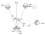
- FIG. 5 is a diagram showing the performance positions of the four performers 10a, 10b, 10c, and 10d in a bird's-eye view (from a top view).
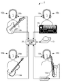
- the performer 10b performs the instrument 14b
- the performer 10c performs the instrument 14c
- the performer 10d performs the instrument 14d, as shown in FIG.
- the performer 10a also plays a musical instrument, which is omitted in FIG.
- Each of the musical instruments 14b, 14c, and 14d outputs performance results as audio signals.
- Examples of such musical instruments typically include electronic (electrical) musical instruments such as electronic pianos, electronic organs, and electric guitars.
- electronic musical instrument has a low volume, however, even if it is an acoustic musical instrument such as a grand (or upright) piano and a folk guitar, a sound collecting device such as a microphone If it is converted into an audio signal, the performance sound providing apparatus 1 can be used.
- the performer 10a wears the headphones 16a.
- An autofocus camera 12a is mounted on the headband of the headphones 16a.
- the image photographed by the camera 12a is supplied to a signal processing device omitted in FIG.
- the signal processing device the image captured by the camera 12a is analyzed, and the azimuth angles of the other performers 10b, 10c, and 10d are detected with respect to the center direction Acntr where the head (face) of the performer 10a faces.
- the azimuth angle is information indicating at what angle the target player is positioned in the left or right direction with respect to the direction Acntr in which a certain player's head faces. is there.
- the signal processing apparatus uses the direction Acntr as a reference as the azimuth angle of the performer 10b with respect to the performer 10a.
- Information indicating that the angle ⁇ ab is in the left direction (counterclockwise in FIG. 5) is output, and the angle ⁇ ac in the right direction (clockwise in FIG. 5) is set as the azimuth angle at which the player 10c is located with respect to the player 10a.
- Information indicating that the player 10d is positioned with respect to the player 10a is output as information indicating that the angle ⁇ ad is in the right direction.
- the signal processing device processes the audio signals output from each of the musical instruments 14b, 14c, and 14d, and applies a stereo signal in which the sound image is localized in the following direction to the headphones 16a worn by the performer 10a.
- Supply That is, the signal processing device localizes the sound image of the musical instrument 14b performed by the player 10b other than the player 10a in the direction Ab of the angle ⁇ ab to the left with respect to the direction Acntr serving as the center for the player 10a.
- the sound image of the musical instrument 14c performed by the performer 10c is localized in the direction of the angle ⁇ ac in the right direction
- the sound image of the instrument 14d performed by the performer 10d is localized in the direction of the angle ⁇ ad in the right direction.
- the signal processing device localizes the sound image of the musical instrument performed by the performer 10a itself, for example, within the head of the performer 10a.
- the sound image of the musical instrument 14b is localized in the direction in which the player 10b is located.
- the sound image of the musical instrument 14c is localized in the direction of the performer 10c, and the sound image of the musical instrument 14c is localized in the direction of the performer 10c.
- the sound image of the musical instrument played by the performer is made to follow the direction of the performer, so that the performance sound with less sense of incongruity and full of realism is provided to the headphone wearer. be able to.
- the signal processing for the headphone 16a of the performer 10a has been described, but the same applies to the signal processing for the headphone 16b of the performer 10b, the headphone 16c of the performer 10c, and the headphone 16d of the performer 10d. is there.
- the above is the outline of the performance sound providing apparatus 1. Next, details of the performance sound providing apparatus 1 will be described.
- FIG. 1 is a diagram showing a configuration of a performance sound providing apparatus 1 according to the first embodiment
- FIG. 2 is a schematic diagram of the performance sound providing apparatus 1.
- the performance sound providing apparatus 1 includes a camera 12a, a musical instrument 14a, and headphones 16a corresponding to the performer 10a, a camera 12b, a musical instrument 14b, and headphones 16b corresponding to the performer 10b, and a performance.
- the camera 12c, the musical instrument 14c, and the headphones 16c corresponding to the player 10c, the camera 12d, the musical instrument 14d, and the headphones 16d corresponding to the performer 10d, and the signal processing device 20 are included.
- each of the cameras 12a to 12d, the musical instruments 14a to 14d, and the headphones 16a to 16d is generally described without corresponding to a specific player, and a, b, c, and d at the end of the reference numerals are used. It explains without attaching.
- the reference numeral is 16 for headphones when the performer is not specified.
- a headphone 16a attached to the performer 10a emits a stereo signal processed by the signal processing device 20.
- the camera 12a is a camera fixed to substantially the midpoint of the headband of the headphone 16a, and the shooting direction is the front side of the sheet in FIG. For this reason, the optical axis direction of the camera 12a substantially coincides with the direction in which the head of the performer 10a faces.
- the angle of view of the camera 12a is preferably such that the other players 10b, 10c, and 10d can be photographed in the same field of view, for example, about 180 degrees. If a situation is assumed in which other performers perform behind the performer 10a, the camera 12a may be an all-round camera.
- the performer 10a plays the musical instrument 14a while wearing the headphones 16a.
- the musical instrument 14 a is an electronic violin.
- the instrument 14 a converts a string vibration into, for example, a digital audio signal by a pickup disposed below the frame, and supplies the digital audio signal to the signal processing device 20.
- the headphones 16b are attached to the performer 10b, and the camera 12b is fixed to almost the midpoint of the headband of the headphones 16b. The other player is photographed, and the musical instrument 14b is played by the player 10b.
- the headphone 16c is attached to the performer 10c, the camera 12c is fixed to substantially the midpoint of the headband of the headphone 16c, and the musical instrument 14c is played by the performer 10c.
- the headphone 16d is attached to the performer 10d, the camera 12d is fixed to substantially the midpoint of the headband of the headphone 16d, and the musical instrument 14d is played by the performer 10d.
- the musical instrument 14b is an electric guitar
- the musical instrument 14c is an electronic piano
- both the musical instruments 14b and 14c supply an audio signal to the signal processing device 20, for example, digitally.
- the musical instrument 14d is a saxophone that is an acoustic musical instrument, and the sound from the saxophone is converted into an audio signal by a sound collecting device inserted in a morning glory tube (bell), and is supplied to the signal processing device 20, for example, digitally.
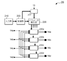
- FIG. 3 is a block diagram illustrating a configuration of the signal processing device 20.
- the signal processing device 20 includes a control unit 200, an input unit 210, a parameter generation unit 220, azimuth angle detection units 215a, 215b, 215c, and 215d, sound image processing units 230a, 230b, 230c and 230d.
- the azimuth angle detection unit 215a and the sound image processing unit 230a correspond to the performer 10a
- the azimuth angle detection unit 215b and the sound image processing unit 230b correspond to the performer 10b
- the azimuth angle detection unit 215c and the sound image processing unit 230c correspond to the player 10d.
- the control unit 200, the azimuth angle detection units 215a, 215b, 215c, and 215d and the parameter generation unit 220 are functional blocks that are constructed when, for example, a CPU (Central Processing Unit) executes a predetermined program.
- a CPU Central Processing Unit
- the azimuth angle detectors 215a, 215b, 215c, and 215d are divided for convenience in order to be explained for each performer, but may be collectively considered as one azimuth angle detector. .
- the input unit 210 is operated by one of the performers and supplies the operation content to the control unit 200.
- the control unit 200 receives content when the player 10 operates the input unit 210 and controls the azimuth angle detection units 215a, 215b, 215c, and 215d and the parameter generation unit 220.
- the azimuth angle detector 215a analyzes the image taken by the camera 12a and detects the azimuth angles of the other players 10b, 10c, and 10d with respect to the player 10a.
- the detection of such an azimuth angle for example, first, the player 10b to be detected is specified by face recognition or the like, and second, when the camera 12a is focused on the face of the specified player 10b. Is obtained from the camera 12a, and thirdly, a distance Rab from the center of the photographed image (center direction Acntr) to the center of the face of the player 10a as the target is obtained. Third, the value of the arc sine obtained by dividing the distance Rab by the distance Lab may be calculated.
- the azimuth angle detection unit 215a performs such detection while specifying other performers photographed by the camera 12a in order from the left to the right of the image, for example. Thereby, the azimuth angle detector 215a detects the azimuth angles of the other players 10b, 10c, and 10d with respect to the player 10a.
- the azimuth angle detection unit 215b detects the azimuth angles of the other players 10a, 10c, and 10d with respect to the player 10b, respectively, and the azimuth angle detection unit 215c detects the other players 10a, 10b, and 10d with respect to the player 10c.
- the azimuth angle is detected, and the azimuth angle detector 215d detects the azimuth angles of the other players 10a, 10b, and 10c with respect to the player 10d.
- the parameter generation unit 220 generates various parameters such as sound image setting filter coefficients and gains based on the azimuth angle output from the azimuth angle detection unit 215a, and supplies the generated parameters to the sound image processing unit 230a. Similarly, the parameter generation unit 220 generates a sound image setting parameter based on the azimuth angle from the azimuth angle detection unit 215b (215c or 315d) and supplies it to the sound image processing unit 230b (230c or 230d).
- the sound image processing units 230a, 230b, 230c, and 230d are a group of digital filters composed of one or a plurality of DSPs (Digital Signal Processors). Note that the sound image processing units 230a, 230c, 230c, and 230d are divided for convenience in order to be explained corresponding to each performer, but can be collectively considered as one sound image processing unit. .
- DSPs Digital Signal Processors
- the sound image processing unit 230a corresponding to the performer 10a performs a sound image localization process defined by parameters by the parameter generation unit 220 on each of the audio signals of the musical instruments 14a, 14b, 14c, and 14d, and performs a sound image localization process.
- Each stereo signal is mixed, converted into an analog signal, amplified, and supplied to the headphone 16a.
- the sound image processing unit 230a for example, the sound image of one musical instrument is localized using the technique described in Japanese Patent Laid-Open No. 10-23600.
- the sound image processing unit 230a since the sound image processing unit 230a localizes the sound images of the four musical instruments, the four signals each localized using the above technique are added and supplied to the headphones 16a.
- the sound image processing unit 230a first delays the audio signal of the musical instrument 14b sequentially by a multi-stage delay circuit, and among these, the signal having the smaller delay time is used as the preceding sound (direct sound). ), And the signal having the longer delay time is extracted as the following sound (initial reflected sound). Secondly, the sound image processing unit 230a performs a convolution operation on the preceding sound and the following sound with, for example, FIR filters of the head-related transfer functions from eight directions to both ears, and performs the player on these FIR filters. The gain corresponding to the direction Ab of 10b is set, and the stereo signal of the musical instrument 14a is output.
- the sound image processing unit 230a similarly processes the audio signals of the musical instruments 14c, 14d, and 14a, and outputs the stereo signal of the musical instrument 14c, the stereo signal of the musical instrument 14d, and the stereo signal of the musical instrument 14a, respectively.
- the sound image processing unit 230a adds these four stereo signals, converts them into analog signals, amplifies them, and supplies them to the headphones 16a.
- the performer 10a wearing the headphones 16a localizes the sound images of the musical instruments 14a, 14b, 14c and 14d in the respective performance directions.
- the sound image processing unit 230b (230c or 230d) is defined by the filter coefficient generated by the parameter generation unit 220 for each of the audio signals of the musical instruments 14a, 14b, 14c, and 14d.
- the sound image localization process is performed, and the stereo signal subjected to the sound image localization process is supplied to the headphones 16b (16c or 16d).
- FIG. 4 is a flowchart showing the operation of the sound image localization process in the signal processing apparatus 20 in the performance sound providing apparatus 1.
- the azimuth angle detection units 215a, 215b, 215c, and 215d and the sound image processing units 230a, 230b, 230b, and 230d are used. May not be attached.
- This sound image localization processing is executed in response to a predetermined operation, for example, an operation on the input unit 210.
- the control unit 200 performs various initial settings (step Sa11).
- This initial setting includes, for example, a process of setting the number of performers and a process of registering the correspondence between the performer 10, the musical instrument 14, and the headphones 16.
- the number of performers for example, the number of musical instruments and the number of sets of headphones connected to the signal processing device 20 may be detected, or any performer 10 may input to the input unit 210.
- the number of performers may be obtained by analyzing (face recognition) an image captured by a certain camera 12 and adding “1” to the number obtained by the analysis.
- the reason why “1” is added to the number of persons obtained by analysis is that the player 10 wearing the headphones 16 becomes a blind spot of the camera 12 mounted on the headphones 16.
- the reason why the correspondence relationship between the performer 10, the musical instrument 14, and the headphones 16 needs to be registered is that, for example, when the performer 10 is identified by face recognition from the photographed image, the identified performer 10 determines which instrument 14 This is because it is necessary to grasp which headphones 16 are worn.
- control unit 200 selects any one of the initially set number of players, that is, pays attention to one player (step Sa12).
- the reason for paying attention to one performer is to select and process the performers one by one in order when supplying the signals in which the sound images are localized to the headphones of all performers. .
- control unit 200 specifies one player other than the player of interest (step Sa13).
- the reason for identifying one of the other performers is that the other performers are processed one by one in order to localize the sound image of the instrument performed by other performers other than the performer of interest. Because.
- the control unit 200 causes the azimuth angle detection unit 215 corresponding to the focused player to detect the azimuth angle of the specific player from the image captured by the camera 12 mounted on the focused player's headphones 16. .
- the azimuth angle detection unit 215 detects the azimuth angle and supplies the azimuth angle to the parameter generation unit 220, and the parameter generation unit 220 acquires the azimuth angle (step Sa14).
- the control unit 200 causes the sound image processing unit 230 corresponding to the player of interest to obtain a sound image of the musical instrument played by the specific player with the acquired azimuth angle.
- the direction is localized (step Sa15).
- control unit 200 causes the parameter generation unit 220 to cause the sound image processing unit 230 corresponding to the player of interest to localize the sound image of the musical instrument played by the specific player in the direction of the acquired azimuth angle. Instructing the supply of the parameter, the sound image processing unit 230 performs a sound image localization process on the audio signal of the musical instrument according to the parameter.
- the control unit 200 determines whether or not the sound image localization processing has been executed for all other players other than the player of interest (step Sa16). If the determination result is “No”, the control unit 200 changes the other player to be identified to a person who has not performed the sound image localization processing (step Sa17), and then returns the processing procedure to step Sa14. In step Sa14 and Sb15, the sound image localization processing of the musical instrument played by the other changed player is executed.
- step Sa16 determines whether or not all the performers have been paid attention to in order (step Sa19). If this determination result is “No”, the control unit 200 changes the focused player to one of the players not focused (step Sa20), and then returns the processing procedure to step Sa12. Then, the processing of steps Sa14 to Sa18 is executed corresponding to the changed focused player.
- step Sa19 determines, for example, the amount of change between the previously acquired azimuth angle and the currently acquired azimuth angle as the focused player. Is determined for all of the specific performers, and it is determined whether or not the average value is equal to or less than a predetermined threshold value (step Sa21).
- step Sa22 If the determination result is “Yes”, that is, if the relative movement of each player 10 is relatively small, the control unit 200 increases the time interval for executing the sound image localization processing by one step (step Sa22). On the other hand, if the determination result is “No”, that is, if the relative movement of each player 10 is relatively large, the control unit 200 further shortens the time interval for executing the sound image localization processing (step Sa23).
- step Sa24 determines whether or not the changed time interval has elapsed since the previous execution. If it has not elapsed (if the determination result in step Sa24 is “No”), the control unit 200 returns the processing procedure to step Sa24. That is, the control unit 200 stands by in step Sa24 until the changed time interval elapses. On the other hand, if the changed time interval has elapsed since the previous execution (if the determination result in step Sa24 is “Yes”), the control unit 200 returns the processing procedure to step Sa12.
- steps Sa12 to Sa24 are executed again, and the other player performs the performance in the direction in which the other player plays on the player's headphone 16 with reference to the direction of the head of the player.
- the process of localizing the sound image of the musical instrument to be performed is executed corresponding to each performer.
- the sound image of the instrument 14b is displayed on the headphone 16a.
- the sound image of the musical instrument 14c is localized in the direction Ac of the performer 10c
- the sound image of the musical instrument 14d is localized in the direction Ad of the performer 10b.
- the player 10a wearing the headphones 16a can experience a sense of reality as if other players are playing at that point.
- the performer 10c moves from the position of the broken line shown in FIG. 7 to the position of the solid line toward the direction Acntr (left side in the drawing), the player 10c is selected in the headphones 16a.
- the sound image of the musical instrument 14c to be played changes with the movement. Specifically, in the sound image localization processing of FIG. 4, when the focused player is the player 10a (step Sa12) and the specific player is the player 10c (step Sa13 or Sa17), the head of the player 10a.
- the azimuth angle detection unit 215a detects that the player 10c is positioned on the left side in the direction Ac 'of the angle ⁇ ac' with respect to the direction Acntr to which the angle is directed, and the detected azimuth angle is acquired by the parameter generation unit 220. (Step Sa14). As a result, the sound image of the musical instrument 14b is localized in the direction Ac ′ by the sound image processing unit 230a (step Sa15).
- the movement of the player 10c is processed in the same manner when the player of interest becomes the player 10b (10d), and the sound image of the instrument 14c is localized at the point after the movement in the headphones 16b (16d).
- the performer 10c moves, even if the other performers 10a, 10b, and 10d do not actually move, the player 10c moves relatively. For this reason, when the focused player becomes the player 10c, the sound images of the musical instruments 14a, 14b, and 14d are localized at the position after the relative movement in the headphones 16c.
- step Sa22 If the average value of the change amount from the direction Ac to Ac ′ of the player 10c viewed from the player 10a and the other change amount exceeds the threshold value, it is determined that the movement is relatively large, and steps Sa12 to Sa24 are performed. The time interval for executing is changed by one step. For this reason, since the sound image localization is frequently executed at short intervals, the sound image can be localized while following the movement. On the other hand, if the average value is less than or equal to the threshold value, it is determined that the movement is relatively small, and the time interval for executing steps Sa12 to Sa24 is changed by one step (step Sa22).
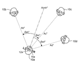
- the other performers 10b, 10c, and 10d Even if they are not actually moving, they are moving relative to the player 10a. For this reason, when the focused performer becomes the performer 10a, the sound images of the musical instruments 14b, 14c, and 14d are localized in the direction after relative movement in the headphones 16a.
- the sound image of the musical instrument 14b is localized in the direction Ab ′′ of the angle ⁇ ab ′′ to the left with respect to the direction Acntr toward the head of the performer 10a, and the sound image of the musical instrument 14c is based on the direction Acntr.
- the sound image of the musical instrument 14d is localized in the direction Ad ′′ at the angle ⁇ ad ′′ with respect to the direction Acntr.
- the performance sound providing apparatus 1 when another player moves relative to a certain target player, the other player performs the movement with the headphone 16 worn by the target player.
- the sound image of the musical instrument 14 to be played also moves. Therefore, even if another player plays the instrument while moving, or the other player's position moves relative to the head due to a change in head direction (center direction), Since the sound image of the musical instrument played by the performer follows the movement of the performer, it is possible to provide a performer wearing headphones with less sense of incongruity and full of realism.
- the azimuth angle of the specific player with respect to the player of interest is detected by analyzing the image photographed by the camera 12, but other than this.
- the configuration can also be detected.
- a second embodiment in which the azimuth angle is detected with another configuration will be described.
- FIG. 9 is a diagram showing a configuration of the performance sound providing apparatus 1 according to the second embodiment
- FIG. 10 is a schematic diagram of the performance sound providing apparatus 1.
- the second embodiment is different from the first embodiment in that a camera 13 is provided instead of the camera 12.
- the camera 13 is an omnidirectional camera that is installed on the ceiling or the like and shoots all directions (360 degrees) from the installation point, that is, shoots all performers at once at the installation point.
- photographed with the camera 13 is supplied to the signal processing apparatus 20 similarly to 1st Embodiment.
- FIG. 11 is a block diagram illustrating a configuration of the signal processing device 20 in the performance sound providing device 1 according to the second embodiment. As shown in this figure, in the signal processing device 20 in the second embodiment, an azimuth angle detector 217 is provided corresponding to the camera 13.
- the camera 13 when the camera 13 is installed on the ceiling, all the performers 10 can be photographed at once. However, since only a part of the player 10, particularly the head, may be photographed, the player 10 cannot be identified by face recognition, and the direction in which the player 10's head faces cannot be detected. It is also assumed.
- the azimuth angle detection unit 217 identifies the performer 10 by, for example, the following image processing, and detects the position of the performer and the direction in which the performer's 10 head faces.
- earphones for both ears of the headphone 16 to be worn by the performer 10 are each provided with a marker that can identify the left and right for each headphone 16 when image processing is performed.
- the azimuth angle detection unit 217 analyzes the image taken by the camera 13 installed on the ceiling, identifies the headphones from the markers attached to the ear cups of both ears, and identifies the performer wearing the headphones. At the same time, the midpoint of the straight line connecting the ear cups of both ears is detected as the position of the performer, and the direction substantially orthogonal to the straight line is detected as the direction in which the head (face) of the performer faces.
- the azimuth angle detection unit 217 uses the midpoint of the straight line connecting the ear cups of both ears as the position of the player 10a wearing the headphone 16a. If the left-ear ear cup (L) is at 9 o'clock and the right-ear ear cup (R) is at 3 o'clock with reference to the midpoint of the straight line, the 12 o'clock direction is Then, the direction Acntr facing the head of the player 10a is detected. Similarly, the azimuth angle detection unit 217 detects the position and the direction of the head, respectively, for the performers 10b, 10c, and 10d.
- the azimuth angle detection unit 217 uses geometric calculations to determine the performance of other players when viewed from one player. Each azimuth can be determined.
- a stereo signal obtained by localizing the sound image of the musical instrument played by the other player at the azimuth angle of the other player is supplied to the headphones worn by the one player. It is the same.
- the player 10 can experience a sense of realism as if he / she is performing while moving, and the camera 12 does not have to be mounted on the headphones 16 according to the second embodiment.
- the burden on the player 10 can be reduced.
- the present invention is not limited to the first embodiment and the second embodiment described above, and various applications and modifications as described below, for example, are possible. Note that one or a plurality of arbitrarily selected aspects of application / deformation described below can be appropriately combined.
- the signal processing device 20 is shared over the performers 10a, 10b, 10c, and 10d, but a signal processing device may be prepared for each performer.
- FIG. 12 shows a signal processing device 20a corresponding to the performer 10a, a signal processing device 20b corresponding to the performer 10b, a signal processing device 20c corresponding to the performer 10c, and a performer 10d.
- signal processing devices 20d are provided. Note that the signal processing device 20a corresponding to the performer 10a detects the azimuths of the performers 10b, 10c, and 10d with respect to the performer 10a from the image captured by the camera 12a, and the performers 10b, 10c, and 10d.
- the sound image of the musical instrument played by the player is localized in the direction of the detected azimuth angle and supplied to the headphones 16a worn by the performer 10a.
- the signal processing device 20b corresponding to the performer 10b detects the azimuths of the performers 10a, 10c, and 10d with respect to the performer 10b from the image captured by the camera 12b, and the performers 10a, 10c, and 10d
- the sound image of the musical instrument to be played is localized in the direction of the detected azimuth angle and supplied to the headphones 16b worn by the performer 10b.
- the sound image of the musical instrument played by the other player is localized in the direction of the azimuth angle of the other player as viewed from a certain player.
- a sensor for detecting the direction of the head of a certain player may be provided.
- this sensor can measure at any angle in either the left or right direction when a player points his head from the initial position (reference position) to the other player. Detect if there was. Then, when the performance is returned to the initial position, the sound image of the musical instrument played by another player may be localized in the direction of the detected azimuth angle.
- the sound image to be given to a certain player's headphones may be configured to be localized in a direction in which the other player is located and a distance from the certain player to the other player. That is, the sound image may be localized at a three-dimensional point in consideration of not only the direction but also the distance.
- the sound image of the musical instrument played by the performer is more precisely the point of the instrument rather than the performer, the instrument is recognized by pattern matching, etc., and is localized in the direction or point where the instrument is recognized. You may let them.
- the musical instrument played by the performer wearing the headphones may be localized at the point of the musical instrument instead of in the head.
- a performer is performing in a virtual space prepared in advance, a sound field in that space is given, and the sound image of the instrument played by another performer is displayed on the performer's headphones. You may localize to the point.
- the virtual space must be prepared in advance, such as halls, churches, and studios, with multiple sizes of space and intensity of reflected sound. As well as how the performer is to be placed in the selected space.
- the sound image to be localized is not limited to musical instruments, and may be a singer. That is, the performance includes singing, and the sound represented by the audio signal includes singing voice.
- the following inventions can be grasped from the viewpoint of minimizing the uncomfortable feeling given to the headphone wearer even when the performer plays the instrument while moving. Is done.
- an azimuth angle detection unit that detects the azimuth angle of the second player with respect to the direction in which the head of the first player is facing, and an audio signal based on the performance by the second player are signal-processed, and the performance Is localized in a direction detected by the azimuth angle detection unit with reference to a direction in which the head of the first player faces, and is output toward a sound emitting device attached to the first player.
- a performance sound providing apparatus including a sound image processing unit is grasped. According to the performance sound providing apparatus, even when the performer plays a musical instrument while moving or the like, the uncomfortable feeling given to the wearer of the sound emitting device such as headphones can be suppressed to a small level.
- “towards” means that another intermediate element such as an amplifier circuit may be interposed in the middle.
- the azimuth angle detection unit analyzes an image photographed by a photographing device collocated on the head of the first performer, and the second performer with respect to the first performer.
- the configuration for detecting the azimuth angle of is determined. According to the above configuration, it is possible to detect the azimuth angle of the second player with respect to the first player without directly obtaining the direction toward the head of the first player.
- the azimuth angle detecting unit analyzes an image obtained by photographing the first player and the second player by a photographing device installed at a predetermined point, and provides the first player with the first sound.
- a configuration for detecting the azimuth angle of the second player is grasped. According to the above configuration, it is possible to reduce the burden on the first performer when detecting the azimuth angle of the second performer with respect to the first performer.
- the azimuth angle acquisition by the direction acquisition unit and the sound image localization by the sound image processing unit are executed at predetermined time intervals. According to the above configuration, the sound image can appropriately follow the change in the orientation of the head of the first player and / or the movement of the second player.
- the azimuth angle obtaining unit obtains a distance from the first player to the second player
- the sound image processing unit obtains a sound image based on the performance by the second player
- the azimuth angle detection unit detects an azimuth angle of the first player with reference to a direction in which the head of the second player is facing, and the sound image processing unit is configured to detect the first player.
- the audio signal based on the performance by the signal is signal-processed, and the sound image based on the performance is localized in the direction detected by the azimuth angle detection unit with respect to the direction in which the head of the second player faces.
- a configuration for output to a sound emitting device attached to the performer is grasped. According to the said structure, a 1st player and a 2nd player can be made to experience an ensemble.
- the computer is based on the performance by the second player with respect to the azimuth angle detecting unit for detecting the azimuth angle of the second player with respect to the direction in which the head of the first player faces, and the sound image processing unit.
- the audio signal is subjected to signal processing, and a sound image based on the performance is localized in a direction acquired by the azimuth acquisition unit with reference to a direction in which the head of the first player faces, and is attached to the first player.
- a recording medium on which a computer program that functions as a control unit that controls to output the sound to the sound emitting device is recorded is grasped. According to the recording medium described above, when the computer functions as a performance sound, even if the performer plays the instrument while moving, the uncomfortable feeling given to the wearer of the sound emitting device such as the headphones can be suppressed. it can.
- Performance sound provision apparatus 10a, 10b, 10c, 10d ... Performer, 12a, 12b, 12c, 12d ... Camera, 14a, 14b, 14c, 14d ... Music instrument, 16a, 16b, 16c, 16d ... Headphone, 20 ... Signal processing device, 200 ... control unit, 215a, 215b, 215c, 215d ... azimuth angle detection unit, 230a, 230b, 230c, 230d ... sound image processing unit.
Landscapes
- Physics & Mathematics (AREA)
- Engineering & Computer Science (AREA)
- Acoustics & Sound (AREA)
- Signal Processing (AREA)
- Stereophonic System (AREA)
Abstract
ヘッドフォン(16a)を装着する演奏者(10a)に対し、他の演奏者(10c)が移動等しながら楽器を演奏する場合であっても、ヘッドフォン(16a)を装着する演奏者(10a)に与える違和感を小さくするため、演奏者(10a)の頭部が向く方向(Acntr)を基準として演奏者(10b)の方位角(θac)を検出し、演奏者(10c)による演奏に基づくオーディオ信号を信号処理して、当該演奏に基づく音像を、方向(Acntr)を基準として方位角(θac)の方向(Ac)に定位させ、演奏者(10a)に装着されたヘッドフォン(16a)に向けて出力する。
Description
本発明は、例えばある演奏者からみて他の演奏者が演奏した楽器の音像を当該他の演奏者の方向に定位させる音像提供装置および記録媒体に関する。
複数の演奏者の各々がそれぞれ楽器を演奏した場合に、各演奏者が装着した放音装置(典型的にはヘッドフォン)において各楽器の音像を各楽器の演奏位置に定位させる技術が知られている(特許文献1参照)。
ところで、演奏によっては、演奏者が移動しながら演奏する場合がある。このような場合に、放音装置の装着者が視認する演奏者の位置と、当該演奏者が演奏する楽器の音像とが一致していないので、当該放音装置の装着者に違和感を与えてしまうことになる。
本発明は、このような事情に鑑みてなされたものであり、その目的の一つは、演奏者が移動等しながら楽器を演奏する場合であっても、放音装置の装着者に与える違和感を小さく抑える技術を提供することにある。
本発明は、このような事情に鑑みてなされたものであり、その目的の一つは、演奏者が移動等しながら楽器を演奏する場合であっても、放音装置の装着者に与える違和感を小さく抑える技術を提供することにある。
上記目的を達成するため、本発明の一態様に係る演奏音提供装置は、第1演奏者の頭部が向く方向を基準として第2演奏者の方位角を検出する方位角検出部と、前記第2演奏者による演奏に基づくオーディオ信号を信号処理して、当該演奏に基づく音像を、前記第1演奏者の頭部が向く方向を基準として前記方位角検出部で検出された方向に定位させ、前記第1演奏者に装着された放音装置に向けて出力する音像処理部と、を含む。
本発明の実施形態に係る演奏音提供装置1の概略について説明する。
なお、演奏音提供装置1では、4人の演奏者で楽器を合奏して、当該4人の演奏者のヘッドフォンの各々に、各楽器の音像をそれぞれ定位させたステレオ信号を供給する場合を想定して説明するが、演奏者の人数を「4」に限定する趣旨ではない。
なお、演奏音提供装置1では、4人の演奏者で楽器を合奏して、当該4人の演奏者のヘッドフォンの各々に、各楽器の音像をそれぞれ定位させたステレオ信号を供給する場合を想定して説明するが、演奏者の人数を「4」に限定する趣旨ではない。
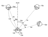
図5は、4人の演奏者10a、10b、10c、および10dの演奏位置を、合奏する場所で俯瞰して(頭上から平面視して)示す図である。また、演奏者のうち、演奏者10bは、図6に示されるように楽器14bを、演奏者10cは楽器14cを、演奏者10dは楽器14dを、それぞれ演奏する。なお、演奏者10aも楽器を演奏するが、図6では省略されている。
楽器14b、14c、および14dの各々は、演奏結果をオーディオ信号で出力する。このような楽器の例としては、典型的には、電子ピアノ、電子オルガン、およびエレクトリックギターなどの電子(電気)楽器などが挙げられる。また、このような電子楽器には、音量が小さいただし、グランド(またはアップライト)ピアノおよびフォークギターなどのようなアコースティックな楽器であっても、当該楽器で発生した音をマイクロフォンなどの収音装置でオーディオ信号に変換すれば、演奏音提供装置1に用いることが可能である。
演奏者10aは、ヘッドフォン16aを装着する。ヘッドフォン16aのヘッドバンドには、オートフォーカスのカメラ12aが同架される。カメラ12aで撮影された画像は、図5では省略された信号処理装置に供給される。信号処理装置では、カメラ12aで撮影された画像を解析して、演奏者10aの頭部(顔)が向くセンター方向Acntrに対し他の演奏者10b、10c、および10dの方位角をそれぞれ検出して出力する。
なお、ここでいう方位角とは、ある演奏者の頭部が向く方向Acntrを基準にして、対象となる演奏者が左右のどちらの方向に、どれだけの角度で位置するかを示す情報である。
なお、ここでいう方位角とは、ある演奏者の頭部が向く方向Acntrを基準にして、対象となる演奏者が左右のどちらの方向に、どれだけの角度で位置するかを示す情報である。
例えば、演奏者10a、10b、10c、および10dが平面視で図5に示されるように位置するとき、信号処理装置は、演奏者10aに対する演奏者10bの方位角として、方向Acntrを基準にして左方向(図5では反時計回り)の角度θabである旨の情報を出力し、演奏者10aに対する演奏者10cが位置する方位角として、右方向(図5では時計回り)の角度θacである旨の情報を出力し、演奏者10aに対する演奏者10dが位置する方位角として、右方向の角度θadである旨の情報を出力する。
また、信号処理装置は、楽器14b、14c、および14dの各々から出力されたオーディオ信号を処理して、次のような方向に音像を定位させたステレオ信号を演奏者10aが装着するヘッドフォン16aに供給する。
すなわち、信号処理装置は、演奏者10a以外の演奏者10bが演奏する楽器14bの音像を、演奏者10aにとってのセンターとなる方向Acntrを基準にして左方向に角度θabの方向Abに定位させ、演奏者10cが演奏する楽器14cの音像を右方向に角度θacの方向Acに定位させ、演奏者10dが演奏する楽器14dの音像を右方向に角度θadの方向Adに定位させる。なお、信号処理装置は、演奏者10a自身が演奏する楽器の音像については、例えば当該演奏者10aの頭内に定位させる。
すなわち、信号処理装置は、演奏者10a以外の演奏者10bが演奏する楽器14bの音像を、演奏者10aにとってのセンターとなる方向Acntrを基準にして左方向に角度θabの方向Abに定位させ、演奏者10cが演奏する楽器14cの音像を右方向に角度θacの方向Acに定位させ、演奏者10dが演奏する楽器14dの音像を右方向に角度θadの方向Adに定位させる。なお、信号処理装置は、演奏者10a自身が演奏する楽器の音像については、例えば当該演奏者10aの頭内に定位させる。
これにより、図6に示されるように、ヘッドフォン16aを装着した演奏者10aからすれば、楽器14bの音像が、演奏者10bの位置する方向に定位する。同様に、演奏者10aからすれば、楽器14cの音像が演奏者10cの方向に、また、楽器14cの音像が演奏者10cの方向に、それぞれ定位する。
そして、このような演奏者の方位角の検出、および、音像の定位を、所定の時間間隔毎に繰り返し実行することで、演奏者が移動しながら演奏したり、ヘッドフォンの装着者の頭部の向きを変化させながら演奏したり場合であっても、当該演奏者が演奏する楽器の音像を当該演奏者の方向に追従させて、違和感の少ない、臨場感あふれる演奏音をヘッドフォン装着者に提供することができる。
そして、このような演奏者の方位角の検出、および、音像の定位を、所定の時間間隔毎に繰り返し実行することで、演奏者が移動しながら演奏したり、ヘッドフォンの装着者の頭部の向きを変化させながら演奏したり場合であっても、当該演奏者が演奏する楽器の音像を当該演奏者の方向に追従させて、違和感の少ない、臨場感あふれる演奏音をヘッドフォン装着者に提供することができる。
なお、ここでは、演奏者10aのヘッドフォン16aについての信号処理について説明したが、演奏者10bのヘッドフォン16b、演奏者10cのヘッドフォン16c、および演奏者10dのヘッドフォン16dについての信号処理についても、同様である。
以上が演奏音提供装置1の概要である。次に、演奏音提供装置1の詳細について説明する。
以上が演奏音提供装置1の概要である。次に、演奏音提供装置1の詳細について説明する。
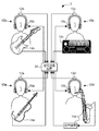
図1は、第1実施形態に係る演奏音提供装置1の構成を示す図であり、図2は、当該演奏音提供装置1の模式図である。
図1に示されるように、演奏音提供装置1は、演奏者10aに対応したカメラ12a、楽器14a、およびヘッドフォン16aと、演奏者10bに対応したカメラ12b、楽器14b、およびヘッドフォン16bと、演奏者10cに対応したカメラ12c、楽器14c、およびヘッドフォン16cと、演奏者10dに対応したカメラ12d、楽器14d、およびヘッドフォン16dと、信号処理装置20とを含む。
なお、カメラ12a~12d、楽器14a~14d、およびヘッドフォン16a~16dの各々については、固有の演奏者に対応させないで一般的に説明する場合には、符号末尾のa、b、c、およびdを付さないで説明する。例えば、演奏者を特定しない場合のヘッドフォンについては符号を16とする。
なお、カメラ12a~12d、楽器14a~14d、およびヘッドフォン16a~16dの各々については、固有の演奏者に対応させないで一般的に説明する場合には、符号末尾のa、b、c、およびdを付さないで説明する。例えば、演奏者を特定しない場合のヘッドフォンについては符号を16とする。
これらの図において、演奏者10aに装着されたヘッドフォン16aは、信号処理装置20によって処理されたステレオ信号を放音する。
カメラ12aは、ヘッドフォン16aのヘッドバンドのほぼ中点に固定されたカメラであり、撮影方向は、図2にあっては紙面手前側である。このため、カメラ12aの光軸方向は、演奏者10aの頭部が向く方向にほぼ一致する。なお、当該カメラ12aの画角は、他の演奏者10b、10c、および10dを同一視野で撮影できる程度、例えば180度程度であることが好ましい。
なお、演奏者10aの背後で他の演奏者が演奏するような状況が想定される場合には、カメラ12aを全周カメラとしても良い。
カメラ12aは、ヘッドフォン16aのヘッドバンドのほぼ中点に固定されたカメラであり、撮影方向は、図2にあっては紙面手前側である。このため、カメラ12aの光軸方向は、演奏者10aの頭部が向く方向にほぼ一致する。なお、当該カメラ12aの画角は、他の演奏者10b、10c、および10dを同一視野で撮影できる程度、例えば180度程度であることが好ましい。
なお、演奏者10aの背後で他の演奏者が演奏するような状況が想定される場合には、カメラ12aを全周カメラとしても良い。
演奏者10aは、ヘッドフォン16aを装着した状態で楽器14aを演奏する。楽器14aは、図2の例でいえば、電子ヴァイオリンであり、駒下に配置されたピックアップによって弦の振動を例えばデジタルのオーディオ信号に変換して、信号処理装置20に供給する。
演奏者10bに対応するカメラ12b、楽器14bおよびヘッドフォン16bも同様であり、ヘッドフォン16bは演奏者10bに装着され、カメラ12bは、ヘッドフォン16bのヘッドバンドのほぼ中点に固定されて、演奏者10b以外の他の演奏者を撮影し、楽器14bは演奏者10bによって演奏される。
同様に、ヘッドフォン16cは演奏者10cに装着され、カメラ12cはヘッドフォン16cのヘッドバンドのほぼ中点に固定され、楽器14cは演奏者10cによって演奏される。ヘッドフォン16dは演奏者10dに装着され、カメラ12dはヘッドフォン16dのヘッドバンドのほぼ中点に固定され、楽器14dは演奏者10dによって演奏される。
同様に、ヘッドフォン16cは演奏者10cに装着され、カメラ12cはヘッドフォン16cのヘッドバンドのほぼ中点に固定され、楽器14cは演奏者10cによって演奏される。ヘッドフォン16dは演奏者10dに装着され、カメラ12dはヘッドフォン16dのヘッドバンドのほぼ中点に固定され、楽器14dは演奏者10dによって演奏される。
なお、この例において、楽器14bはエレクトリックギターであり、楽器14cは電子ピアノであり、楽器14bおよび14cのいずれもオーディオ信号を例えばデジタルで信号処理装置20に供給する。また、楽器14dはアコースティック楽器であるサクソフォンであり、当該サクソフォンからの音を、朝顔管(ベル)に挿入された収音装置でオーディオ信号に変換し、例えばデジタルで信号処理装置20に供給する。
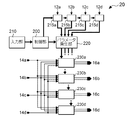
図3は、信号処理装置20の構成を示すブロック図である。この図に示されるように信号処理装置20は、制御部200と、入力部210と、パラメータ発生部220と、方位角検出部215a、215b、215c、および215dと、音像処理部230a、230b、230c、および230dと、を含む。
このうち、方位角検出部215aおよび音像処理部230aは演奏者10aに対応し、方位角検出部215bおよび音像処理部230bは演奏者10bに対応し、方位角検出部215cおよび音像処理部230cは演奏者10cに対応し、方位角検出部215dおよび音像処理部230dは演奏者10dに対応する。
このうち、方位角検出部215aおよび音像処理部230aは演奏者10aに対応し、方位角検出部215bおよび音像処理部230bは演奏者10bに対応し、方位角検出部215cおよび音像処理部230cは演奏者10cに対応し、方位角検出部215dおよび音像処理部230dは演奏者10dに対応する。
制御部200、方位角検出部215a、215b、215c、215dおよびパラメータ発生部220は、例えばCPU(Central Processing Unit)が所定のプログラムを実行することによって構築される機能ブロックである。
なお、方位角検出部215a、215b、215c、215dについては、演奏者毎に対応させて説明するため便宜的に分けているが、まとめて1つの方位角検出部として概念することも可能である。
なお、方位角検出部215a、215b、215c、215dについては、演奏者毎に対応させて説明するため便宜的に分けているが、まとめて1つの方位角検出部として概念することも可能である。
入力部210は、いずれかの演奏者によって操作され、その操作内容を制御部200に供給する。制御部200は、演奏者10が入力部210を操作したときの内容を受け付けるとともに、方位角検出部215a、215b、215c、215dおよびパラメータ発生部220を制御する。
方位角検出部215aは、カメラ12aで撮影された画像を解析して、演奏者10aに対する他の演奏者10b、10cおよび10dの方位角をそれぞれ検出する。
このような方位角の検出については、例えば第1に、顔認識等により検出の対象となる演奏者10bを特定し、第2に、特定した演奏者10bの顔にカメラ12aが合焦したときの距離Lab(図5参照)の情報を当該カメラ12aから取得し、第3に、撮影された画像の中心(センター方向Acntr)から当該対象となる演奏者10aの顔の中心までの距離Rabを求め、第3に、距離Rabを距離Labで除した逆正弦(アークサイン)の値を算出すれば良い。
方位角検出部215aは、このような検出について、カメラ12aで撮影された他の演奏者を例えば画像の左から右に向かって順番に特定しながら実行する。これにより、方位角検出部215aは、演奏者10aに対する他の演奏者10b、10cおよび10dの方位角をそれぞれ検出する。
このような方位角の検出については、例えば第1に、顔認識等により検出の対象となる演奏者10bを特定し、第2に、特定した演奏者10bの顔にカメラ12aが合焦したときの距離Lab(図5参照)の情報を当該カメラ12aから取得し、第3に、撮影された画像の中心(センター方向Acntr)から当該対象となる演奏者10aの顔の中心までの距離Rabを求め、第3に、距離Rabを距離Labで除した逆正弦(アークサイン)の値を算出すれば良い。
方位角検出部215aは、このような検出について、カメラ12aで撮影された他の演奏者を例えば画像の左から右に向かって順番に特定しながら実行する。これにより、方位角検出部215aは、演奏者10aに対する他の演奏者10b、10cおよび10dの方位角をそれぞれ検出する。
同様に、方位角検出部215bは演奏者10bに対する他の演奏者10a、10cおよび10dの方位角をそれぞれ検出し、方位角検出部215cは演奏者10cに対する他の演奏者10a、10bおよび10dの方位角をそれぞれ検出し、方位角検出部215dは演奏者10dに対する他の演奏者10a、10bおよび10cの方位角をそれぞれ検出する。
パラメータ発生部220は、方位角検出部215aから出力される方位角に基づき音像設定用のフィルタ係数およびゲイン等の各種のパラメータを生成して、音像処理部230aに供給する。同様に、パラメータ発生部220は、方位角検出部215b(215cまたは315d)からの方位角に基づき音像設定用のパラメータを生成して、音像処理部230b(230cまたは230d)に供給する。
音像処理部230a、230b、230c、および230dは、1個または複数個のDSP(Digital Signal Processor)で構成されるデジタルフィルタ群である。なお、音像処理部230a、230c、230c、および230dについては、演奏者毎に対応させて説明するために便宜的に分けているが、まとめて1つの音像処理部として概念することも可能である。
演奏者10aに対応する音像処理部230aは、楽器14a、14b、14c、および14dのオーディオ信号の各々に、パラメータ発生部220によるパラメータで規定される音像定位処理を施し、当音像定位処理を施した各ステレオ信号をミキシングし、アナログ変換および増幅した上で、ヘッドフォン16aに供給する。なお、音像処理部230aでは、例えば1つの楽器の音像を、特開平10-23600号公報に記載された技術を用いて定位させる。本例において音像処理部230aでは、4つの楽器の音像を定位させるので、上記技術を用いてそれぞれ定位させた4つの信号を加算してヘッドフォン16aに供給する。
上記技術について簡単に説明すれば、音像処理部230aは、第1に、楽器14bのオーディオ信号を多段の遅延回路で順次遅延させ、このうち、遅延時間の小さい方の信号を先行音(直接音)として取り出し、遅延時間の大きい方の信号を後行音(初期反射音)として取り出す。音像処理部230aは、第2に、当該先行音および当該後行音を、例えば8つの方向から両耳への頭部伝達関数のFIRフィルタで畳み込み演算するとともに、これらのFIRフィルタに対し演奏者10bの方向Abに対応したゲインを設定して、楽器14aのステレオ信号を出力する。
音像処理部230aは、楽器14c、14dおよび14aのオーディオ信号についても同様に処理して、楽器14cのステレオ信号と、楽器14dのステレオ信号と、楽器14aのステレオ信号をそれぞれ出力する。そして、音像処理部230aは、これらの4つのステレオ信号を加算し、アナログ信号に変換し、増幅した上でヘッドフォン16aに供給する。
これによりヘッドフォン16aを装着した演奏者10aは、楽器14a、14b、14cおよび14dの音像がそれぞれの演奏方向で定位することになる。
音像処理部230aは、楽器14c、14dおよび14aのオーディオ信号についても同様に処理して、楽器14cのステレオ信号と、楽器14dのステレオ信号と、楽器14aのステレオ信号をそれぞれ出力する。そして、音像処理部230aは、これらの4つのステレオ信号を加算し、アナログ信号に変換し、増幅した上でヘッドフォン16aに供給する。
これによりヘッドフォン16aを装着した演奏者10aは、楽器14a、14b、14cおよび14dの音像がそれぞれの演奏方向で定位することになる。
音像処理部230b(230cまたは230d)についても、音像処理部230aと同様に、楽器14a、14b、14c、および14dのオーディオ信号の各々に、パラメータ発生部220で生成されたフィルタ係数で規定される音像定位処理を施し、当音像定位処理を施したステレオ信号をヘッドフォン16b(16cまたは16d)に供給する。
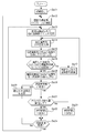
図4は、演奏音提供装置1のうち、おもに信号処理装置20における音像定位処理の動作を示すフローチャートである。
なお、方位角検出部215a、215b、215c、および215dと、音像処理部230a、230b、230b、および230dとについて、一般的に説明するために、符号末尾のa、b、c、およびdを付さない場合がある。
なお、方位角検出部215a、215b、215c、および215dと、音像処理部230a、230b、230b、および230dとについて、一般的に説明するために、符号末尾のa、b、c、およびdを付さない場合がある。
この音像定位処理は、所定の操作、例えば入力部210に対する操作を契機として実行される。
まず、信号処理装置20において、制御部200は、各種の初期設定をする(ステップSa11)。この初期設定には、例えば、演奏者の人数を設定する処理と、演奏者10、楽器14およびヘッドフォン16の対応関係を登録する処理等とが含まれる。
なお、演奏者の人数については、例えば信号処理装置20に接続される楽器数およびヘッドフォンの組数を検出しても良いし、いずれかの演奏者10が入力部210に入力しても良いし、ある1つのカメラ12で撮影された画像を解析(顔認識)し、解析して求めた人数に「1」を加えて、演奏者の人数としても良い。ここで、解析して求めた人数に「1」を加える理由は、ヘッドフォン16を装着した演奏者10については当該ヘッドフォン16に同架されたカメラ12の死角となるためである。
また、演奏者10、楽器14およびヘッドフォン16の対応関係を登録する必要がある理由は、例えば撮影された画像から顔認識により演奏者10を識別したときに、識別した演奏者10がどの楽器14を演奏し、どのヘッドフォン16を装着しているかを把握する必要があるからである。
まず、信号処理装置20において、制御部200は、各種の初期設定をする(ステップSa11)。この初期設定には、例えば、演奏者の人数を設定する処理と、演奏者10、楽器14およびヘッドフォン16の対応関係を登録する処理等とが含まれる。
なお、演奏者の人数については、例えば信号処理装置20に接続される楽器数およびヘッドフォンの組数を検出しても良いし、いずれかの演奏者10が入力部210に入力しても良いし、ある1つのカメラ12で撮影された画像を解析(顔認識)し、解析して求めた人数に「1」を加えて、演奏者の人数としても良い。ここで、解析して求めた人数に「1」を加える理由は、ヘッドフォン16を装着した演奏者10については当該ヘッドフォン16に同架されたカメラ12の死角となるためである。
また、演奏者10、楽器14およびヘッドフォン16の対応関係を登録する必要がある理由は、例えば撮影された画像から顔認識により演奏者10を識別したときに、識別した演奏者10がどの楽器14を演奏し、どのヘッドフォン16を装着しているかを把握する必要があるからである。
次に、制御部200は、初期設定された人数の演奏者のうち、いずれか1人の演奏者を選択してすなわち、1人の演奏者に着目する(ステップSa12)。なお、ここで1人の演奏者について着目する理由は、演奏者全員の各ヘッドフォンに音像を定位させた信号をそれぞれ供給するにあたって、演奏者を順番に1人ずつ選択して処理するためである。
続いて、制御部200は、着目演奏者以外の他の演奏者のうち、1人を特定する(ステップSa13)。なお、他の演奏者のうち、1人を特定する理由は、着目する演奏者以外の他の演奏者が演奏する楽器の音像を定位させるにあたって、他の演奏者を順番に1人ずつ処理するためである。
制御部200は、着目演奏者に対応する方位角検出部215に対して、当該着目演奏者のヘッドフォン16に同架されたカメラ12で撮影された画像から、特定演奏者の方位角を検出させる。これにより、方位角検出部215は、当該方位角を検出して当該方位角をパラメータ発生部220に供給して、パラメータ発生部220は、当該方位角を取得する(ステップSa14)。
着目演奏者に対する特定演奏者の方位角を取得させると、制御部200は、着目演奏者に対応する音像処理部230に対し、特定演奏者が演奏する楽器の音像を、当該取得した方位角の方向に定位させる(ステップSa15)。具体的には、制御部200は、パラメータ発生部220に対して、着目演奏者に対応する音像処理部230に、特定演奏者が演奏する楽器の音像を、取得した方位角の方向に定位させるパラメータの供給を指示し、音像処理部230は、当該パラメータにしたがって当該楽器のオーディオ信号に対して音像定位処理を施す。
着目演奏者に対する特定演奏者の方位角を取得させると、制御部200は、着目演奏者に対応する音像処理部230に対し、特定演奏者が演奏する楽器の音像を、当該取得した方位角の方向に定位させる(ステップSa15)。具体的には、制御部200は、パラメータ発生部220に対して、着目演奏者に対応する音像処理部230に、特定演奏者が演奏する楽器の音像を、取得した方位角の方向に定位させるパラメータの供給を指示し、音像処理部230は、当該パラメータにしたがって当該楽器のオーディオ信号に対して音像定位処理を施す。
制御部200は、着目演奏者以外の他の演奏者の全員について音像定位処理をそれぞれ実行したか否かを(ステップSa16)。
この判別結果が「No」であれば、制御部200は、特定する他の演奏者を、音像定位処理をしていない者に変更し(ステップSa17)、この後に、処理手順をステップSa14に戻し、変更した他の演奏者が演奏する楽器の音像定位処理を、ステップSa14およびSb15で実行する。
この判別結果が「No」であれば、制御部200は、特定する他の演奏者を、音像定位処理をしていない者に変更し(ステップSa17)、この後に、処理手順をステップSa14に戻し、変更した他の演奏者が演奏する楽器の音像定位処理を、ステップSa14およびSb15で実行する。
一方、制御部200は、ステップSa16の判別結果が「Yes」であれば、すなわち、着目演奏者以外の他の演奏者が演奏する楽器の各々についての音像定位処理を実行したならば、着目演奏者が演奏する楽器の音像定位処理を実行して、当該楽器の音像を例えば着目演奏者の頭内に定位させる(ステップSa18)。
ステップSa18が終了すると、着目演奏者10のヘッドフォン16についてすべての楽器の音像を定位させたことになる。このため、制御部200は、次に、演奏者の全員について順番に着目したか否かを判別する(ステップSa19)。
この判別結果が「No」であれば、制御部200は、着目する演奏者を、着目していない演奏者の1人に変更し(ステップSa20)、この後に、処理手順をステップSa12に戻して、変更した着目演奏者に対応してステップSa14~Sa18の処理を実行する。
ステップSa18が終了すると、着目演奏者10のヘッドフォン16についてすべての楽器の音像を定位させたことになる。このため、制御部200は、次に、演奏者の全員について順番に着目したか否かを判別する(ステップSa19)。
この判別結果が「No」であれば、制御部200は、着目する演奏者を、着目していない演奏者の1人に変更し(ステップSa20)、この後に、処理手順をステップSa12に戻して、変更した着目演奏者に対応してステップSa14~Sa18の処理を実行する。
ステップSa19の判別結果が「Yes」であれば、すなわち、演奏者全員に着目したならば、制御部200は、例えば前回取得した方位角と今回取得した方位角との変化量を、着目演奏者に対する特定演奏者についてすべてに求めて、その平均値が予め定められた閾値以下であるか否かを判別する(ステップSa21)。
この判別結果が「Yes」であれば、すなわち、各演奏者10の相対移動が比較的小さければ、制御部200は、音像定位処理を実行する時間間隔を一段長くする(ステップSa22)。
一方、この判別結果が「No」であれば、すなわち、各演奏者10の相対移動が比較的大きければ、制御部200は、音像定位処理を実行する時間間隔を一段短くする(ステップSa23)。
一方、この判別結果が「No」であれば、すなわち、各演奏者10の相対移動が比較的大きければ、制御部200は、音像定位処理を実行する時間間隔を一段短くする(ステップSa23)。
ステップSa22またはSa23の処理後、制御部200は、変更した時間間隔が前回の実行時から経過したか否かを判別する(ステップSa24)。
経過していなかったら(ステップSa24の判別結果が「No」であれば)、制御部200は、処理手順をステップSa24に戻す。すなわち、制御部200は、変更した時間間隔が経過するまで、ステップSa24で待機する。
一方、変更した時間間隔が前回の実行時から経過すれば(ステップSa24の判別結果が「Yes」であれば)、制御部200は、処理手順をステップSa12に戻す。
これにより、再びステップSa12~Sa24が実行されて、演奏者のヘッドフォン16に、当該演奏者の頭部の向く方向に基準にして他の演奏者が演奏する方向に、当該他の演奏者が演奏する楽器の音像を定位させる処理が、演奏者の各々に対応して実行される。
経過していなかったら(ステップSa24の判別結果が「No」であれば)、制御部200は、処理手順をステップSa24に戻す。すなわち、制御部200は、変更した時間間隔が経過するまで、ステップSa24で待機する。
一方、変更した時間間隔が前回の実行時から経過すれば(ステップSa24の判別結果が「Yes」であれば)、制御部200は、処理手順をステップSa12に戻す。
これにより、再びステップSa12~Sa24が実行されて、演奏者のヘッドフォン16に、当該演奏者の頭部の向く方向に基準にして他の演奏者が演奏する方向に、当該他の演奏者が演奏する楽器の音像を定位させる処理が、演奏者の各々に対応して実行される。
例えば4人の演奏者10a、10b、10c、および10dが上述した図5に示されるような位置で合奏する場合、図6に示されるように、ヘッドフォン16aでは、楽器14bの音像が演奏者10bの方向Abで、楽器14cの音像が演奏者10cの方向Acで、また、楽器14dの音像が演奏者10bの方向Adで、それぞれ定位する。このため、当該ヘッドフォン16aを装着する演奏者10aは、他の演奏者があたかもその地点で演奏しているかのような臨場感を体験することができる。
また、4人の演奏者のうち、例えば演奏者10cが図7に示される破線の位置から方向Acntr寄り(図において左側)に実線の位置まで移動したとき、ヘッドフォン16aでは、当該演奏者10cが演奏する楽器14cの音像が当該移動に伴って変化する。詳細には、図4の音像定位処理において、着目演奏者が演奏者10aであり(ステップSa12)、特定演奏者が演奏者10cであるときに(ステップSa13またはSa17)、演奏者10aの頭部が向く方向Acntrに対し、演奏者10cが左側で角度θac'の方向Ac'に位置する旨が方位角検出部215aで検出されて、当該検出された方位角がパラメータ発生部220に取得される(ステップSa14)。これにより、音像処理部230aによって、楽器14bの音像が方向Ac'に定位される(ステップSa15)。
なお、演奏者10cの移動は、着目演奏者が演奏者10b(10d)となったときも同様に処理されて、ヘッドフォン16b(16d)では、移動後の地点で楽器14cの音像が定位する。
一方、演奏者10cが移動したとき、他の演奏者10a、10b、および10dが実際には移動していなくても、演奏者10cからみれば、相対的に移動していることになる。このため、着目演奏者が演奏者10cとなったときに、ヘッドフォン16cでは、相対的な移動後の地点で楽器14a、14b、および14dの音像が定位する。
一方、演奏者10cが移動したとき、他の演奏者10a、10b、および10dが実際には移動していなくても、演奏者10cからみれば、相対的に移動していることになる。このため、着目演奏者が演奏者10cとなったときに、ヘッドフォン16cでは、相対的な移動後の地点で楽器14a、14b、および14dの音像が定位する。
演奏者10aからみた演奏者10cの方向AcからAc’への変化量と、他の変化量との平均値が閾値を超えていれば、比較的移動が多いと判断されて、ステップSa12~Sa24を実行する時間間隔が1段短く変更される。このため、音像定位が短い間隔で頻繁に実行されるので、その移動に追従しながら、音像を定位させることができる。
一方、上記平均値が閾値以下であれば、比較的移動が少ないと判断されて、ステップSa12~Sa24を実行する時間間隔が1段長く変更される(ステップSa22)。
一方、上記平均値が閾値以下であれば、比較的移動が少ないと判断されて、ステップSa12~Sa24を実行する時間間隔が1段長く変更される(ステップSa22)。
4人の演奏者のうち、例えば演奏者10aだけが頭部を、図5に示される方向Acntrから図8に示される方向Acntr''に向けたとき、他の演奏者10b、10c、および10dが実際には移動していなくても、演奏者10aからみれば、相対的に移動していることになる。このため、着目演奏者が演奏者10aとなったときに、ヘッドフォン16aでは、楽器14b、14c、および14dの各音像が相対的な移動後の方向にそれぞれ定位される。
詳細には、楽器14bの音像は、演奏者10aの頭部が向く方向Acntrを基準にして左方向に角度θab''の方向Ab''に定位され、楽器14cの音像が方向Acntrを基準にして右方向に角度θac''の方向Ac''に定位され、楽器14dの音像が方向Acntrを基準にして右方向に角度θad''の方向Ad''に定位される。
詳細には、楽器14bの音像は、演奏者10aの頭部が向く方向Acntrを基準にして左方向に角度θab''の方向Ab''に定位され、楽器14cの音像が方向Acntrを基準にして右方向に角度θac''の方向Ac''に定位され、楽器14dの音像が方向Acntrを基準にして右方向に角度θad''の方向Ad''に定位される。
このように演奏音提供装置1では、ある着目演奏者に対して他の演奏者が相対的に移動したとき、当該着目演奏者が装着するヘッドフォン16では、当該移動に伴って他の演奏者が演奏する楽器14の音像も移動する。このため、他の演奏者が移動しながら楽器を演奏しても、また、頭部の向き(センター方向)が変化して他の演奏者の位置が相対的に移動しても、当該他の演奏者が演奏する楽器の音像が、当該演奏者の移動に追従するので、違和感の少ない、臨場感あふれる演奏音を、ヘッドフォンを装着する演奏者に提供することができる。
ところで、第1実施形態に係る演奏音提供装置1では、着目演奏者に対する特定演奏者の方位角を、カメラ12で撮影された画像を解析することにより検出する構成としたが、これに以外の構成でも検出可能である。そこで次に、方位角について別の構成で検出する第2実施形態について説明する。
図9は、第2実施形態に係る演奏音提供装置1の構成を示す図であり、図10は、当該演奏音提供装置1の模式図である。
第2実施形態が第1実施形態と相違する点は、カメラ12の代わりにカメラ13が設けられている点にある。カメラ13は、天井などに設置されて、当該設置地点から全方位(360度)を撮影する、すなわち設置地点において演奏者全員を1度で撮影する全天球型のカメラである。
なお、カメラ13で撮影された画像は、第1実施形態と同様に、信号処理装置20に供給される。
なお、カメラ13で撮影された画像は、第1実施形態と同様に、信号処理装置20に供給される。
図11は、第2実施形態に係る演奏音提供装置1における信号処理装置20の構成を示すブロック図である。
この図に示されるように、第2実施形態における信号処理装置20では、方位角検出部217がカメラ13に対応して設けられる。
この図に示されるように、第2実施形態における信号処理装置20では、方位角検出部217がカメラ13に対応して設けられる。
第2実施形態において、カメラ13が天井に設置された場合、演奏者10の全員を1度に撮影することができる。しかしながら、演奏者10の一部、特に頭部しか撮影されない場合があるので、顔認識によっては演奏者10を識別することができず、また、演奏者10の頭部が向く方向についても検出できないことも想定される。
そこで第2実施形態では、方位角検出部217が、例えば次のような画像処理によって演奏者10を識別するとともに、演奏者の位置と、演奏者10の頭部が向く方向とを検出する。
まず、事前準備として、演奏者10の装着が予定されるヘッドフォン16における両耳のイヤーカップに、画像処理したときにヘッドフォン16毎に、かつ、左右を識別可能なマーカーをそれぞれ付しておく。
まず、事前準備として、演奏者10の装着が予定されるヘッドフォン16における両耳のイヤーカップに、画像処理したときにヘッドフォン16毎に、かつ、左右を識別可能なマーカーをそれぞれ付しておく。
方位角検出部217は、天井に設置されたカメラ13で撮影された画像を解析し、両耳のイヤーカップに付されたマーカーからヘッドフォンを識別して、当該ヘッドフォンを装着する演奏者を識別するとともに、両耳のイヤーカップを結ぶ直線の中点を当該演奏者の位置と検出し、当該直線に対してほぼ直交する方向を当該演奏者の頭部(顔)が向く方向として検出する。
具体的には、例えば図5において、方位角検出部217は、マーカーからヘッドフォン16aを識別したとき、両耳のイヤーカップを結ぶ直線の中点を、当該ヘッドフォン16aを装着する演奏者10aの位置と検出し、当該直線の中点を基準に左耳のイヤーカップ(L)が9時の方向であり、右耳のイヤーカップ(R)が3時の方向であれば、12時の方向を、当該演奏者10aの頭部の向く方向Acntrと検出する。
方位角検出部217は、演奏者10b、10c、および10dについても同様にして、位置および頭部の向く方向をそれぞれ検出する。
方位角検出部217は、演奏者10b、10c、および10dについても同様にして、位置および頭部の向く方向をそれぞれ検出する。
各演奏者10a、10b、10c、および10dの位置および頭部の向く方向が判れば、方位角検出部217は、幾何学計算により、ある1人の演奏者からみたときの他の演奏者の方位角をそれぞれ求めることができる。
なお、当該ある1人の演奏者が装着するヘッドフォンに、他の演奏者の方位角に当該他の演奏者が演奏する楽器の音像を定位させたステレオ信号を供給する点については第1実施形態と同様である。
なお、当該ある1人の演奏者が装着するヘッドフォンに、他の演奏者の方位角に当該他の演奏者が演奏する楽器の音像を定位させたステレオ信号を供給する点については第1実施形態と同様である。
第2実施形態によれば、違和感が小さく、移動しながら演奏しているかのような臨場感を演奏者10に体験させることができるとともに、カメラ12をヘッドフォン16にを同架させなくて済むので、演奏者10への負担感を減らすことができる。
本発明は、上述した第1実施形態および第2実施形態に限定されるものではなく、例えば次に述べるような各種の応用・変形が可能である。なお、次に述べる応用・変形の態様は、任意に選択された一または複数を適宜に組み合わせることもできる。
第1実施形態および第2実施形態では、演奏者10a、10b、10c、および10dにわたって信号処理装置20を共用したが、演奏者毎に信号処理装置を用意しても良い。
図12は、演奏者10aに対応して信号処理装置20aを、演奏者10bに対応して信号処理装置20bを、演奏者10cに対応して信号処理装置20cを、演奏者10dに対応して信号処理装置20dを、それぞれ設けた例である。
なお、演奏者10aに対応する信号処理装置20aは、カメラ12aで撮影された画像から、演奏者10aに対する演奏者10b、10c、および10dの方位角を検出するとともに、演奏者10b、10c、10dが演奏する楽器の音像を、検出した方位角の方向にそれぞれ定位させて、演奏者10aが装着するヘッドフォン16aに供給する。
演奏者10bに対応する信号処理装置20bは、カメラ12bで撮影された画像から、演奏者10bに対する演奏者10a、10c、および10dの方位角を検出するとともに、演奏者10a、10c、および10dが演奏する楽器の音像を、検出した方位角の方向にそれぞれ定位させて、演奏者10bが装着するヘッドフォン16bに供給する。
演奏者10cに対応する信号処理装置20c、および、演奏者10dに対応する信号処理装置20dについても同様である。
図12は、演奏者10aに対応して信号処理装置20aを、演奏者10bに対応して信号処理装置20bを、演奏者10cに対応して信号処理装置20cを、演奏者10dに対応して信号処理装置20dを、それぞれ設けた例である。
なお、演奏者10aに対応する信号処理装置20aは、カメラ12aで撮影された画像から、演奏者10aに対する演奏者10b、10c、および10dの方位角を検出するとともに、演奏者10b、10c、10dが演奏する楽器の音像を、検出した方位角の方向にそれぞれ定位させて、演奏者10aが装着するヘッドフォン16aに供給する。
演奏者10bに対応する信号処理装置20bは、カメラ12bで撮影された画像から、演奏者10bに対する演奏者10a、10c、および10dの方位角を検出するとともに、演奏者10a、10c、および10dが演奏する楽器の音像を、検出した方位角の方向にそれぞれ定位させて、演奏者10bが装着するヘッドフォン16bに供給する。
演奏者10cに対応する信号処理装置20c、および、演奏者10dに対応する信号処理装置20dについても同様である。
第1実施形態および第2実施形態では、ある演奏者からみて他の演奏者の方位角の方向に当該他の演奏者が演奏する楽器の音像を定位させる構成であった。
ここで、ある演奏者の頭部の向く方向を検出するセンサーを設けても良い。このセンサーは、例えば他の演奏者の方位角について、ある演奏者が頭部を初期位置(基準位置)から当該他の演奏者に向けたときに、左右のどちらの方向にどれだけの角度であったのかを検出する。そして、演奏時には初期位置に戻したときに、検出した方位角の方向に、他の演奏者が演奏する楽器の音像を定位させれば良い。
ここで、ある演奏者の頭部の向く方向を検出するセンサーを設けても良い。このセンサーは、例えば他の演奏者の方位角について、ある演奏者が頭部を初期位置(基準位置)から当該他の演奏者に向けたときに、左右のどちらの方向にどれだけの角度であったのかを検出する。そして、演奏時には初期位置に戻したときに、検出した方位角の方向に、他の演奏者が演奏する楽器の音像を定位させれば良い。
ある演奏者のヘッドフォンに与える音像については、他の演奏者が位置する方向であって、当該ある演奏者から当該他の演奏者までの距離の地点に定位させる構成としても良い。すなわち、音像を、方向のみならず、距離を考慮した三次元の地点に定位させても良い。また、演奏者が演奏する楽器の音像は、より正確にいえば、当該演奏者ではなく、楽器の地点であるから、楽器をパターンマッチングなどで認識して、楽器を認識した方向または地点に定位させても良い。
くわえて、ヘッドフォンを装着する演奏者が演奏する楽器についても、頭内ではなく、当該楽器の地点に定位させても良い。
くわえて、ヘッドフォンを装着する演奏者が演奏する楽器についても、頭内ではなく、当該楽器の地点に定位させても良い。
演奏者が予め用意された仮想的な空間で合奏すると想定し、その空間での音場を付与した上で、ある演奏者のヘッドフォンに、他の演奏者の演奏する楽器の音像を、当該演奏の地点に定位させても良い。
なお、仮想的な空間としては、ホール、チャーチ、およびスタジオなどのように空間の大きさ、および反射音の強さなどを予め複数用意しておくともに、いずかの演奏者が所望の空間を選択するとともに、選択した空間に対して演奏者がどのように配置するのかを入力すれば良い。
なお、仮想的な空間としては、ホール、チャーチ、およびスタジオなどのように空間の大きさ、および反射音の強さなどを予め複数用意しておくともに、いずかの演奏者が所望の空間を選択するとともに、選択した空間に対して演奏者がどのように配置するのかを入力すれば良い。
定位させる音像については、楽器に限られず、歌唱者でも良い。すなわち、演奏には歌唱も含まれ、オーディオ信号が表す音には、歌唱音声も含まれる。
上述した実施形態や、応用・変形の態様からは、演奏者が移動等しながら楽器を演奏する場合であっても、ヘッドフォン装着者に与える違和感を小さく抑える、という観点より、以下の発明が把握される。
まず、第1演奏者の頭部が向く方向を基準として第2演奏者の方位角を検出する方位角検出部と、前記第2演奏者による演奏に基づくオーディオ信号を信号処理して、当該演奏に基づく音像を、前記第1演奏者の頭部が向く方向を基準として前記方位角検出部で検出された方向に定位させ、前記第1演奏者に装着された放音装置に向けて出力する音像処理部と、を含む演奏音提供装置が把握される。上記演奏音提供装置によれば、演奏者が移動等しながら楽器を演奏する場合であっても、ヘッドフォンのような放音装置の装着者に与える違和感を小さく抑えることができる。
なお、「に向けて」とは、途中に別の中間要素、例えば増幅回路などが介在しても良い、という意味である。
なお、「に向けて」とは、途中に別の中間要素、例えば増幅回路などが介在しても良い、という意味である。
上記演奏音提供装置において、前記方位角検出部は、前記第1演奏者の頭部に同架された撮影装置により撮影された画像を解析して、前記第1演奏者に対する前記第2演奏者の方位角を検出する構成が把握される。上記構成によれば、第1演奏者に対する第2演奏者の方位角を、第1演奏者の頭部を向く方向を直接求めることなく、検出することができる。
上記演奏音提供装置において、前記方位角検出部は、所定の地点に設置された撮影装置が前記第1演奏者および前記第2演奏者を撮影した画像を解析して、前記第1演奏者に対する前記第2演奏者の方位角を検出する構成が把握される。上記構成によれば、第1演奏者に対する第2演奏者の方位角を検出するにあたって、第1演奏者に与える負担感を減らすことができる。
上記演奏音提供装置において、前記方向取得部による方位角の取得、および、前記音像処理部による音像の定位は、それぞれ所定の時間間隔で実行される構成が把握される。上記構成によれば、第1演奏者の頭部の向きの変化、または/および、第2演奏者の移動に音像を適度に追従させることができる。
上記演奏音提供装置において、前記方位角取得部は、前記第1演奏者から前記第2演奏者までの距離を取得し、前記音像処理部は、前記第2演奏者による演奏に基づく音像を、前記第1演奏者の頭部が向く方向を基準として前記方位取得部で取得された方向および距離の地点に定位させる構成が把握される。上記構成によれば、音像の定位の精度を向上させることができる。
上記演奏音提供装置において、前記方位角検出部は、前記第2演奏者の頭部が向く方向を基準として第1演奏者の方位角を検出し、前記音像処理部は、前記第1演奏者による演奏に基づくオーディオ信号を信号処理して、当該演奏に基づく音像を、前記第2演奏者の頭部が向く方向を基準として前記方位角検出部で検出された方向に定位させ、前記第2演奏者に装着された放音装置に向けて出力する構成が把握される。上記構成によれば、第1演奏者および第2演奏者に合奏を体験させることができる。
また、コンピュータを、第1演奏者の頭部が向く方向を基準として第2演奏者の方位角を検出する方位角検出部、および、音像処理部に対し、前記第2演奏者による演奏に基づくオーディオ信号を信号処理して、当該演奏に基づく音像を、前記第1演奏者の頭部が向く方向を基準として前記方位取得部で取得された方向に定位させ、前記第1演奏者に装着された放音装置に向けて出力するように制御する制御部として機能させるコンピュータプログラムを記録した記録媒体が把握される。上記記録媒体によれば、コンピュータを演奏音提供として機能させる場合に、演奏者が移動等しながら楽器を演奏しても、ヘッドフォンのような放音装置の装着者に与える違和感を小さく抑えることができる。
1…演奏音提供装置、10a、10b、10c、10d…演奏者、12a、12b、12c、12d…カメラ、14a、14b、14c、14d…楽器、16a、16b、16c、16d…ヘッドフォン、20…信号処理装置、200…制御部、215a、215b、215c、215d…方位角検出部、230a、230b、230c、230d…音像処理部。
Claims (6)
- 第1演奏者の頭部が向く方向を基準として第2演奏者の方位角を検出する方位角検出部と、
前記第2演奏者による演奏に基づくオーディオ信号を信号処理して、当該演奏に基づく音像を、前記第1演奏者の頭部が向く方向を基準として前記方位角検出部で検出された方向に定位させ、前記第1演奏者に装着された放音装置に向けて出力する音像処理部と、
を含む演奏音提供装置。 - 前記方位角検出部は、
前記第1演奏者の頭部に同架された撮影装置により撮影された画像を解析して、前記第1演奏者に対する前記第2演奏者の方位角を検出する
請求項1の演奏音提供装置。 - 前記方位角検出部は、
所定の地点に設置された撮影装置が前記第1演奏者および前記第2演奏者を撮影した画像を解析して、前記第1演奏者に対する前記第2演奏者の方位角を検出する
請求項1の演奏音提供装置。 - 前記方向取得部による方位角の取得、および、前記音像処理部による音像の定位は、それぞれ所定の時間間隔で実行される
請求項1に記載の演奏音提供装置。 - 前記方位角検出部は、
前記第2演奏者の頭部が向く方向を基準として第1演奏者の方位角を検出し、
前記音像処理部は、
前記第1演奏者による演奏に基づくオーディオ信号を信号処理して、当該演奏に基づく音像を、前記第2演奏者の頭部が向く方向を基準として前記方位角検出部で検出された方向に定位させ、前記第2演奏者に装着された放音装置に向けて出力する
請求項1に記載の演奏音提供装置。 - コンピュータを、
第1演奏者の頭部が向く方向を基準として第2演奏者の方位角を検出する方位角検出部、および、
音像処理部に対し、前記第2演奏者による演奏に基づくオーディオ信号を信号処理して、当該演奏に基づく音像を、前記第1演奏者の頭部が向く方向を基準として前記方位取得部で取得された方向に定位させ、前記第1演奏者に装着された放音装置に向けて出力するように制御する制御部、
として機能させるコンピュータプログラムを記録した記録媒体。
Priority Applications (1)
| Application Number | Priority Date | Filing Date | Title |
|---|---|---|---|
| PCT/JP2016/087890 WO2018116368A1 (ja) | 2016-12-20 | 2016-12-20 | 演奏音提供装置および記録媒体 |
Applications Claiming Priority (1)
| Application Number | Priority Date | Filing Date | Title |
|---|---|---|---|
| PCT/JP2016/087890 WO2018116368A1 (ja) | 2016-12-20 | 2016-12-20 | 演奏音提供装置および記録媒体 |
Publications (1)
| Publication Number | Publication Date |
|---|---|
| WO2018116368A1 true WO2018116368A1 (ja) | 2018-06-28 |
Family
ID=62626955
Family Applications (1)
| Application Number | Title | Priority Date | Filing Date |
|---|---|---|---|
| PCT/JP2016/087890 Ceased WO2018116368A1 (ja) | 2016-12-20 | 2016-12-20 | 演奏音提供装置および記録媒体 |
Country Status (1)
| Country | Link |
|---|---|
| WO (1) | WO2018116368A1 (ja) |
Cited By (5)
| Publication number | Priority date | Publication date | Assignee | Title |
|---|---|---|---|---|
| WO2022196073A1 (ja) * | 2021-03-18 | 2022-09-22 | ソニーグループ株式会社 | 情報処理装置、情報処理方法、およびプログラム |
| JP2022189036A (ja) * | 2021-06-10 | 2022-12-22 | トヨタ紡織株式会社 | 制御装置、制御システム、および制御方法 |
| JP2023092583A (ja) * | 2021-12-22 | 2023-07-04 | カシオ計算機株式会社 | 情報処理装置、音出力装置、情報処理方法及びプログラム |
| GB2627540A (en) * | 2023-04-12 | 2024-08-28 | Bonza Music Ltd | A system and method for immersive musical performance between at least two remote locations over a network |
| US20240430558A1 (en) * | 2023-06-23 | 2024-12-26 | Otto Edward Collins | Headphones embodying a wearable audio-video recording and tracking system |
Citations (3)
| Publication number | Priority date | Publication date | Assignee | Title |
|---|---|---|---|---|
| JP2004088608A (ja) * | 2002-08-28 | 2004-03-18 | Yamaha Corp | ミキシング装置 |
| JP2005295181A (ja) * | 2004-03-31 | 2005-10-20 | Victor Co Of Japan Ltd | 音声情報生成装置 |
| JP2011097268A (ja) * | 2009-10-28 | 2011-05-12 | Sony Corp | 再生装置、ヘッドホン及び再生方法 |
-
2016
- 2016-12-20 WO PCT/JP2016/087890 patent/WO2018116368A1/ja not_active Ceased
Patent Citations (3)
| Publication number | Priority date | Publication date | Assignee | Title |
|---|---|---|---|---|
| JP2004088608A (ja) * | 2002-08-28 | 2004-03-18 | Yamaha Corp | ミキシング装置 |
| JP2005295181A (ja) * | 2004-03-31 | 2005-10-20 | Victor Co Of Japan Ltd | 音声情報生成装置 |
| JP2011097268A (ja) * | 2009-10-28 | 2011-05-12 | Sony Corp | 再生装置、ヘッドホン及び再生方法 |
Cited By (10)
| Publication number | Priority date | Publication date | Assignee | Title |
|---|---|---|---|---|
| WO2022196073A1 (ja) * | 2021-03-18 | 2022-09-22 | ソニーグループ株式会社 | 情報処理装置、情報処理方法、およびプログラム |
| US20240163624A1 (en) * | 2021-03-18 | 2024-05-16 | Sony Group Corporation | Information processing device, information processing method, and program |
| JP2022189036A (ja) * | 2021-06-10 | 2022-12-22 | トヨタ紡織株式会社 | 制御装置、制御システム、および制御方法 |
| JP7632097B2 (ja) | 2021-06-10 | 2025-02-19 | トヨタ紡織株式会社 | 制御装置、制御システム、および制御方法 |
| JP2023092583A (ja) * | 2021-12-22 | 2023-07-04 | カシオ計算機株式会社 | 情報処理装置、音出力装置、情報処理方法及びプログラム |
| JP7826684B2 (ja) | 2021-12-22 | 2026-03-10 | カシオ計算機株式会社 | 電子鍵盤楽器、情報処理方法及びプログラム |
| GB2627540A (en) * | 2023-04-12 | 2024-08-28 | Bonza Music Ltd | A system and method for immersive musical performance between at least two remote locations over a network |
| WO2024213865A1 (en) | 2023-04-12 | 2024-10-17 | Bonza Music Limited | A system and method for immersive musical performance between at least two remote locations over a network |
| GB2627540B (en) * | 2023-04-12 | 2025-04-16 | Bonza Music Ltd | A system and method for immersive musical performance between at least two remote locations over a network |
| US20240430558A1 (en) * | 2023-06-23 | 2024-12-26 | Otto Edward Collins | Headphones embodying a wearable audio-video recording and tracking system |
Similar Documents
| Publication | Publication Date | Title |
|---|---|---|
| JP6665379B2 (ja) | 聴覚支援システムおよび聴覚支援装置 | |
| US10097921B2 (en) | Methods circuits devices systems and associated computer executable code for acquiring acoustic signals | |
| CN108369811B (zh) | 分布式音频捕获和混合 | |
| US10812926B2 (en) | Sound output device, sound generation method, and program | |
| US10165386B2 (en) | VR audio superzoom | |
| WO2018116368A1 (ja) | 演奏音提供装置および記録媒体 | |
| CA2765116C (en) | Method and apparatus for processing audio signals | |
| US20150326963A1 (en) | Real-time Control Of An Acoustic Environment | |
| JP2021520760A (ja) | 音源の位置特定 | |
| KR101678305B1 (ko) | 텔레프레즌스를 위한 하이브리드형 3d 마이크로폰 어레이 시스템 및 동작 방법 | |
| Geronazzo et al. | Superhuman hearing-virtual prototyping of artificial hearing: a case study on interactions and acoustic beamforming | |
| JP2018191127A (ja) | 信号生成装置、信号生成方法およびプログラム | |
| JP6587047B2 (ja) | 臨場感伝達システムおよび臨場感再現装置 | |
| JP6550756B2 (ja) | オーディオ信号処理装置 | |
| JP2016134767A (ja) | オーディオ信号処理装置 | |
| CN116913328B (zh) | 音频处理方法、电子设备及存储介质 | |
| JP3750198B2 (ja) | 音像定位装置 | |
| JP2004088608A (ja) | ミキシング装置 | |
| JP2017175256A (ja) | ヘッドホン | |
| JP2005051801A (ja) | 音像定位装置 | |
| US20190306618A1 (en) | Methods circuits devices systems and associated computer executable code for acquiring acoustic signals | |
| JP2002304191A (ja) | 鳴き声による音声ガイドシステム | |
| JP2002142299A (ja) | 聴覚補助装置 | |
| WO2025197425A1 (ja) | スピーカ装置、音信号処理方法及びプログラム | |
| WO2026063142A1 (ja) | 音信号処理方法および音信号処理装置 |
Legal Events
| Date | Code | Title | Description |
|---|---|---|---|
| 121 | Ep: the epo has been informed by wipo that ep was designated in this application |
Ref document number: 16924339 Country of ref document: EP Kind code of ref document: A1 |
|
| NENP | Non-entry into the national phase |
Ref country code: DE |
|
| 122 | Ep: pct application non-entry in european phase |
Ref document number: 16924339 Country of ref document: EP Kind code of ref document: A1 |
|
| NENP | Non-entry into the national phase |
Ref country code: JP |