WO2018116361A1 - コンピュータシステム、入退室管理方法及びプログラム - Google Patents
コンピュータシステム、入退室管理方法及びプログラム Download PDFInfo
- Publication number
- WO2018116361A1 WO2018116361A1 PCT/JP2016/087848 JP2016087848W WO2018116361A1 WO 2018116361 A1 WO2018116361 A1 WO 2018116361A1 JP 2016087848 W JP2016087848 W JP 2016087848W WO 2018116361 A1 WO2018116361 A1 WO 2018116361A1
- Authority
- WO
- WIPO (PCT)
- Prior art keywords
- terminal
- exit
- computer
- entrance
- computer system
- Prior art date
- Legal status (The legal status is an assumption and is not a legal conclusion. Google has not performed a legal analysis and makes no representation as to the accuracy of the status listed.)
- Ceased
Links
Images




Classifications
-
- G—PHYSICS
- G07—CHECKING-DEVICES
- G07C—TIME OR ATTENDANCE REGISTERS; REGISTERING OR INDICATING THE WORKING OF MACHINES; GENERATING RANDOM NUMBERS; VOTING OR LOTTERY APPARATUS; ARRANGEMENTS, SYSTEMS OR APPARATUS FOR CHECKING NOT PROVIDED FOR ELSEWHERE
- G07C9/00—Individual registration on entry or exit
Definitions
- the present invention relates to a computer system, an entrance / exit management method, and a program used in places where entrance / exit is restricted.
- an entrance / exit management system for an office, a facility, or the like restricts the entry / exit of the owner of the recording medium by reading the identification information recorded on a recording medium such as a dedicated card with a reader such as a card reader. Corresponding entry / exit management is performed.
- Patent Document 1 is not convenient because even a regular worker cannot enter the room when the recording medium is lost or not carried.
- An object of the present invention is to provide a computer system, an entrance / exit management method, and a program that improve convenience by substituting an application such as a portable terminal for a recording medium.
- the present invention provides the following solutions.
- the present invention is a computer system used in a place where entry and exit are restricted, Registration means for performing registration of the current location of the terminal within the location; Control means for permitting admission to the terminal in which the internal position is registered; A computer system is provided.
- a computer system used in a place where entrance / exit is restricted performs registration of the current position of the terminal inside the place, and for the terminal in which the internal position is registered, Allow admission.
- the present invention is a computer system category, but the same actions and effects according to the category are exhibited in other categories such as an entrance / exit management method and program.
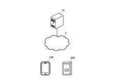
- FIG. 1 is a diagram showing an outline of an entrance / exit management system 1.
- FIG. 2 is an overall configuration diagram of the entrance / exit management system 1.
- FIG. 3 is a functional block diagram of the computer 10, the portable terminal 100, and the reading device 200.
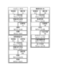
- FIG. 4 is a flowchart showing registration processing executed by the computer 10 and the portable terminal 100.
- FIG. 5 is a flowchart showing registration processing executed by the computer 10 and the portable terminal 100.
- FIG. 6 is a flowchart showing an unlocking process executed by the computer 10, the portable terminal 100, and the reading device 200.
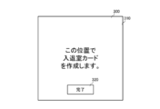
- FIG. 7 is a diagram illustrating an example of an entry / exit card creation screen.
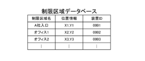
- FIG. 8 is a diagram illustrating an example of a restricted area database.
- FIG. 9 is a diagram illustrating an example of the permission database.
- FIG. 1 is a diagram for explaining the outline of an entrance / exit management system 1 which is a preferred embodiment of the present invention.
- the entrance / exit management system 1 includes a computer 10, a portable terminal 100, and a reading device 200, and is a computer system used in places where entrance / exit is restricted.
- the number of computers 10, portable terminals 100, and reading devices 200 can be changed as appropriate.
- the computer 10, the mobile terminal 100, and the reading device 200 are not limited to real devices, and may be virtual devices.
- each process to be described later may be realized by any one or a combination of the computer 10, the mobile terminal 100, and the reading device 200.
- the computer 10 is a computer device connected to the mobile terminal 100 and the reading device 200 so as to be able to perform data communication.
- the computer 10 may be a network device such as a router connected to the portable terminal 100 and the reading device 200 via a LAN.
- the portable terminal 100 is a terminal device that is connected to the computer 10 so as to be able to perform data communication, and is connected to the reading device 200 via NFC (Near Field Communication).
- the portable terminal 100 is, for example, a mobile phone, a portable information terminal, a tablet terminal, a personal computer, an electric appliance such as a netbook terminal, a slate terminal, an electronic book terminal, a portable music player, a smart glass, a head-mounted display, etc. Wearable terminals and other items.
- the reading device 200 is an NFC compatible terminal that is installed inside and outside a restricted area where entry and exit are restricted, and can communicate with the mobile terminal 100 via NFC.
- the reading device 200 reads a recording medium such as a card that records a user identification number, whether or not a restricted area can be entered, and various information of the mobile terminal 100.
- the mobile terminal 100 activates an entry / exit application (step S01).
- the portable terminal 100 activates the entry / exit application in response to activation input of the entry / exit application from the user.
- the mobile terminal 100 acquires its own location information from the GPS, stores this location information, and creates a virtual entrance / exit card at this location (step S02).
- the mobile terminal 100 sends its own location information and terminal ID (an identifier that can uniquely identify the mobile terminal 100 such as a preset character string, telephone number, device number, MAC address, IP address) to the computer 10. Transmit (step S03).
- terminal ID an identifier that can uniquely identify the mobile terminal 100 such as a preset character string, telephone number, device number, MAC address, IP address
- the computer 10 receives the location information of the mobile terminal 100 and the terminal ID, and confirms whether this location information is location information within the restricted area (step S04).
- the computer 10 When the computer 10 matches the position information in the restricted area stored in advance, the computer 10 associates the received position information with the terminal ID and registers it as a permission ID (step S05). At this time, the computer 10 may further register the device ID of the reading device 200 (name, a preset character string, an identifier that can uniquely identify the reading device 200 such as a device number) in association with the permission ID. Good.
- the device ID of the reading device 200 name, a preset character string, an identifier that can uniquely identify the reading device 200 such as a device number
- the reading device 200 reads the terminal ID of the portable terminal 100 by receiving the radio wave from the portable terminal 100 (step S06). At this time, for example, the portable terminal 100 activates an entry / exit application upon receiving radio waves, and the reading device 200 reads the terminal ID via the entry / exit application.
- the reading device 200 transmits this terminal ID to the computer 10 (step S07).
- the computer 10 receives the terminal ID and checks whether or not the terminal ID matches the permission ID (step S08).
- the computer 10 transmits a notification indicating that the terminal ID matches the reading device 200 (step S09).
- the reading device 200 receives this notification and permits entry to the mobile terminal 200 (step S10).
- the reading device 200 permits the user to enter and leave the room by unlocking an unlocking device (not shown).
- FIG. 2 is a diagram showing a system configuration of the entrance / exit management system 1 which is a preferred embodiment of the present invention.
- the entrance / exit management system 1 includes a computer 10, a portable terminal 100, a reading device 200, and a public network (such as the Internet network and third and fourth generation communication networks) 5, and is used in places where entrance and exit are restricted.
- Computer system is a diagram showing a system configuration of the entrance / exit management system 1 which is a preferred embodiment of the present invention.
- the entrance / exit management system 1 includes a computer 10, a portable terminal 100, a reading device 200, and a public network (such as the Internet network and third and fourth generation communication networks) 5, and is used in places where entrance and exit are restricted. Computer system.
- each device constituting the entrance / exit management system 1 can be changed as appropriate. Further, the entrance / exit management system 1 is not limited to a real device, and may be realized by virtual devices. Moreover, each process mentioned later may be implement
- the computer 10 is the above-described computer device having the functions described below.
- the mobile terminal 100 is the above-described terminal device having the functions described below.
- the reading apparatus 200 is the above-described NFC compatible terminal having the functions described below.
- FIG. 3 is a functional block diagram of the computer 10, the portable terminal 100, and the reading device 200.
- the computer 10 includes a CPU (Central Processing Unit), a RAM (Random Access Memory), a ROM (Read Only Memory), etc. as the control unit 11, and a device for enabling communication with other devices as the communication unit 12. For example, a device compatible with WiFi (Wireless Fidelity) compliant with IEEE 802.11 is provided.
- the computer 10 also includes a data storage unit such as a hard disk, a semiconductor memory, a recording medium, or a memory card as the storage unit 13.
- control unit 11 reads a predetermined program, thereby realizing the data transmission / reception module 20 and the unlocking instruction transmission module 21 in cooperation with the communication unit 12.
- control module 11 reads a predetermined program, thereby realizing the management module 30 and the storage module 31 in cooperation with the storage unit 13.
- the mobile terminal 100 includes a CPU, RAM, ROM, and the like as the control unit 110, a device for enabling communication with other devices as the communication unit 120, and a data Storage unit.
- the portable terminal 100 serves as an input / output unit 140 such as a display unit that outputs and displays data and images controlled by the control unit 110, an input unit such as a touch panel, a keyboard, and a mouse that accepts input from the user, and a GPS itself.
- Various devices such as a device for acquiring the position information of the device.
- the data transmission / reception module 150 and the radio wave reception module 151 are realized in cooperation with the communication unit 120 by the control unit 110 reading a predetermined program.
- the storage module 160 is realized in cooperation with the storage unit 130 by the control unit 110 reading a predetermined program.
- the control unit 110 reads a predetermined program, thereby realizing the application module 170, the position information acquisition module 171, and the card creation module 172 in cooperation with the input / output unit 140.
- the reading device 200 includes a CPU, RAM, ROM, and the like as the control unit 210, and a device for enabling communication with other devices as the communication unit 220.
- the reading unit 240 includes a device that performs non-contact communication such as NFC and reads various information of the mobile terminal 100.
- the data transmission / reception module 250 and the unlocking instruction receiving module 251 are realized in cooperation with the communication unit 220 by the control unit 210 reading a predetermined program.
- the reading unit 270 and the control module 271 are realized in cooperation with the reading unit 240 by the control unit 210 reading a predetermined program.
- FIG.4 and FIG.5 are flowcharts of registration processing executed by the computer 10 and the portable terminal 100.
- FIG. 4 and 5 The processing executed by the modules of each device described above will be described together with this processing.
- Application module 170 activates an entry / exit application (step S20).
- the application module 170 activates the entry / exit application by receiving the activation input of the entry / exit application from the user.
- the position information acquisition module 171 acquires its own position information (step S21). In step S21, the position information acquisition module 171 acquires its own position information from GPS or the like. The position information acquisition module 171 acquires position information by receiving input from the user to the entry / exit application. Note that the location information acquisition module 171 may acquire the SSID in a network device such as a router connected to the LAN as its location information.
- Storage module 160 stores position information (step S22).
- the card creation module 172 displays an entry / exit card creation screen (step S23).
- FIG. 7 is a diagram illustrating an example of an entry / exit card creation screen.
- the card creation module 172 displays a content display area 310 and a completion icon 320 as the entrance / exit card creation screen 300.
- the content display area 310 is an area for displaying a description of the contents of this screen, and notifies the user that an entry / exit card will be created based on the current location information.
- the completion icon 320 is an icon that accepts input from the user. Upon accepting input from the user, an entry / exit card is created and the display of this screen is terminated.
- the card creation module 172 creates an entry / exit card (step S24).
- the card creation module 172 creates an entry / exit card as a virtual card for entering / exiting the restricted area.
- the entry / exit card includes a terminal ID of the mobile terminal 100 (an identifier that can uniquely identify the mobile terminal 100 such as a preset character string, telephone number, device number, MAC address, IP address, etc.) Position information is associated.
- the storage module 160 stores the created entry / exit card (step S25).
- the data transmitting / receiving module 150 transmits its own location information and terminal ID as management data to the computer 10 (step S26).
- the data transmission / reception module 20 receives management data.
- the management module 30 includes an identifier of a restricted area (name, information that can uniquely identify a restricted area such as a preset character string), position information in the restricted area, and the reading device 200 stored in the storage module 31 in advance.
- Position information included in the received management data with reference to a restricted area database that associates the device ID (information that can uniquely identify the reading device 200 such as a name, a preset character string, and a device number) Is registered (step S27).
- the management module 30 makes a determination based on whether or not the position information included in the restricted area database matches the position information included in the management data.
- the restricted area database will be described with reference to FIG. FIG. 8 is a diagram illustrating an example of a restricted area database.
- the storage module 31 stores a restricted area name, position information, and a device ID in association with each other as a restricted area database.
- the restricted area name is an identifier of the restricted area.
- the restricted area name is, for example, an entrance of a company or facility, an office name, a character string preset in the office, or a department name in the company or facility.
- the position information is position information within the restricted area. This position information is, for example, predetermined coordinates or coordinates in a predetermined range.
- the device ID is an identifier of the reading device 200.
- the device ID is, for example, the name of the reading device 200, a preset character string, and a device number.
- the items registered in the restricted area database are not limited to the examples described above, and other items may be added and can be changed as appropriate. Similarly, the contents of each item can be changed as appropriate.
- step S27 if the management module 30 determines that the location information of the management data is not registered in the restricted area database (NO in step S27), the process ends.
- the computer 10 creates an error notification (for example, a notification screen indicating that it is not registered, a warning sound), and the mobile terminal 100 notifies the error (for example, the mobile terminal 100 notifies Screen display and warning sound) may be displayed.
- step S27 when the management module 30 determines in step S27 that the location information of the management data is registered in the restricted area database (YES in step S27), the storage module 31 stores the management data and the restricted area in the restricted area database.
- the device ID of the provided reading device 200 is registered in the permission database (step S28).
- step S28 the storage module 31 may register only management data as a permission database.
- the permission database will be described based on FIG. FIG. 9 is a diagram illustrating an example of the permission database.
- the storage module 31 stores a terminal ID, position information, and a device ID in association with each other.
- the terminal ID is an identifier that identifies the mobile terminal 100.
- the terminal ID is, for example, a preset character string, telephone number, device number, MAC address, or IP address.
- the position information is position information at the current position of the mobile terminal 100.
- the position information is, for example, latitude / longitude, coordinate system, and SSID.
- the device ID is an identifier of the reading device 200.
- the reading device name is, for example, the name of the reading device 200, a preset character string, and a device number.
- FIG. 6 is a diagram illustrating a flowchart of unlocking processing executed by the computer 10, the portable terminal 100, and the reading device 200. The processing executed by the modules of each device described above will be described together with this processing.
- the radio wave receiving module 151 determines whether or not a radio wave is received from the reading device 200 (step S30).
- the radio wave reception module 151 receives radio waves by NFC. For example, when the user holds the portable terminal 100 over the reading device 200, the portable terminal 100 receives radio waves from the reading device 200.
- step S30 when the radio wave receiving module 151 determines that it has not received (step S30: NO), this process is repeated.
- step S31 the application module 170 activates the entry / exit application (step S31).
- the application module 170 activates an entry / exit application and displays the above-described entry / exit card.
- step S31 the application module 170 is not limited to receiving radio waves, and may activate an entry / exit application based on an activation input from a user and display an entry / exit card. In this case, you may abbreviate
- the reading module 270 receives radio waves from the mobile terminal 100 and reads the terminal ID of the mobile terminal 100 (step S32). In step S32, the reading module 270 reads the terminal ID by reading the entry / exit card.
- the data transmitting / receiving module 250 transmits the read terminal ID and its own device ID as read result data to the computer 10 (step S33).
- the data transmission / reception module 250 may transmit only the read terminal ID as the read result data, or read the position information of the reading device 200 or the position information of the portable terminal 100 instead of the device ID. It may be transmitted as data.
- the data transmission / reception module 20 receives the read result data.
- the management module 30 refers to the permission database and determines whether or not the terminal ID and device ID included in the read result data are registered in association with the location information of the restricted area (step S34). In step S34, the management module 30 determines whether the terminal ID and the device ID are registered in the permission database, and the location information of the place in the restricted area that the user is trying to unlock this time is associated with them. Determine whether. That is, it is determined whether or not the terminal ID of the mobile terminal 100 functions as an electronic key for a place where entry / exit is restricted.
- the management module 30 may determine whether or not it is registered in the permission database based only on the terminal ID.
- the management module 30 refers to the permission database based on the position information of the mobile terminal 100 and the terminal ID, and the position information associated with the terminal ID matches the position information acquired this time. It may be determined based on whether or not.
- step S34 if the management module 30 determines that it is not registered (NO in step S34), the process is terminated.
- the computer 10 creates an error notification (for example, a notification screen indicating that it is not registered, a warning sound), and the mobile terminal 100 or the reading device 200 notifies the user of this error notification.
- an error notification for example, a notification screen indicating that it is not registered, a warning sound
- the mobile terminal 100 or the reading device 200 notifies the user of this error notification.
- either or both of the mobile terminal 100 and the reading device 200 emit a display of a notification screen and a warning sound.
- step S34 determines in step S34 that it is registered (YES in step S34)
- the unlock instruction transmission module 21 transmits the unlock instruction to the reading device 200 (step S35).
- the unlock instruction receiving module 251 receives the unlock instruction. Based on this release instruction, the control module 271 permits entry to the mobile terminal 100 (step S36). In step S36, the control module 271 unlocks the electronic lock applied to the door and permits the user of the mobile terminal 100 to enter and leave the room as permission for entry.
- the computer 10 may transmit a notification indicating that it has been registered to the reading device 200 instead of the release instruction, and the reading device 200 may permit admission based on this notification.
- each process executed by the computer 10 described above may be executed instead by the reading device 200.
- the reading device 200 may execute the function executed by each module of the computer 10 instead.
- the means and functions described above are realized by a computer (including a CPU, an information processing apparatus, and various terminals) reading and executing a predetermined program.
- the program is provided, for example, in a form (SaaS: Software as a Service) provided from a computer via a network.
- the program is provided in a form recorded on a computer-readable recording medium such as a flexible disk, CD (CD-ROM, etc.), DVD (DVD-ROM, DVD-RAM, etc.).
- the computer reads the program from the recording medium, transfers it to the internal storage device or the external storage device, stores it, and executes it.
- the program may be recorded in advance in a storage device (recording medium) such as a magnetic disk, an optical disk, or a magneto-optical disk, and provided from the storage device to a computer via a communication line.
- Entrance / exit management system 10 computer, 100 mobile terminal, 200 reader
Landscapes
- Physics & Mathematics (AREA)
- General Physics & Mathematics (AREA)
- Time Recorders, Dirve Recorders, Access Control (AREA)
Abstract
【課題】利便性を向上させたコンピュータシステム、入退室管理方法及びプログラムを提供することを目的とする。 【解決手段】入退室が制限される場所で利用されるコンピュータシステムは、前記場所の内部で、端末の現在位置の登録を実行し、前記内部の位置が登録された端末に対して、入場の許可を行う。また、コンピュータシステムは、前記場所に設けられたNFC対応端末の電波を受信し、前記電波を受信した際、所定のアプリケーションを起動する。また、コンピュータシステムは、前記NFC対応端末の識別子と、前記現在位置とを対応付けて登録をし、前記内部の位置とNFC対応端末の識別子とが登録された端末に対して、入場の許可を行う。
Description
本発明は、入退室が制限される場所で利用されるコンピュータシステム、入退室管理方法及びプログラムに関する。
従来、オフィスや施設等への入退室管理システムは、専用のカード等の記録媒体に記録された識別情報をカードリーダ等の読取装置で読み取ることより、この記録媒体の所持者の入退室制限に対応した入退室管理を行っている。
このような入退室管理システムにおいて、読取装置で記録媒体を読み取るとともに、監視カメラにより、作業者を識別することにより、不審者を判別する構成が開示されている(特許文献1参照)。
しかしながら、特許文献1の構成では、正規な作業者であっても、記録媒体の紛失や不携帯時には、入室することができないため、利便性が低かった。
本発明は、記録媒体を携帯端末等のアプリケーションで代用することにより、利便性を向上させたコンピュータシステム、入退室管理方法及びプログラムを提供することを目的とする。
本発明では、以下のような解決手段を提供する。
本発明は、入退室が制限される場所で利用されるコンピュータシステムであって、
前記場所の内部で、端末の現在位置の登録を実行する登録手段と、
前記内部の位置が登録された端末に対して、入場の許可を行う制御手段と、
を備えることを特徴とするコンピュータシステムを提供する。
前記場所の内部で、端末の現在位置の登録を実行する登録手段と、
前記内部の位置が登録された端末に対して、入場の許可を行う制御手段と、
を備えることを特徴とするコンピュータシステムを提供する。
本発明によれば、入退室が制限される場所で利用されるコンピュータシステムは、前記場所の内部で、端末の現在位置の登録を実行し、前記内部の位置が登録された端末に対して、入場の許可を行う。
本発明は、コンピュータシステムのカテゴリであるが、入退室管理方法及びプログラム等の他のカテゴリにおいても、そのカテゴリに応じた同様の作用・効果を発揮する。
本発明によれば、利便性を向上させたコンピュータシステム、入退室管理方法及びプログラムを提供することが可能となる。
以下、本発明を実施するための最良の形態について図を参照しながら説明する。なお、これはあくまでも一例であって、本発明の技術的範囲はこれに限られるものではない。
[入退室管理システム1の概要]
本発明の好適な実施形態の概要について、図1に基づいて説明する。図1は、本発明の好適な実施形態である入退室管理システム1の概要を説明するための図である。入退室管理システム1は、コンピュータ10、携帯端末100、読取装置200から構成され、入退室が制限される場所で使用されるコンピュータシステムである。
本発明の好適な実施形態の概要について、図1に基づいて説明する。図1は、本発明の好適な実施形態である入退室管理システム1の概要を説明するための図である。入退室管理システム1は、コンピュータ10、携帯端末100、読取装置200から構成され、入退室が制限される場所で使用されるコンピュータシステムである。
なお、図1において、コンピュータ10、携帯端末100、読取装置200の数は、適宜変更可能である。また、コンピュータ10、携帯端末100、読取装置200は、実在する装置に限らず、仮想的な装置であってもよい。また、後述する各処理は、コンピュータ10、携帯端末100、読取装置200のいずれか又は複数の組み合わせにより実現されてもよい。
コンピュータ10は、携帯端末100、読取装置200とデータ通信可能に接続されたコンピュータ装置である。なお、コンピュータ10は、携帯端末100、読取装置200とLAN接続されたルータ等のネットワーク装置であってもよい。
携帯端末100は、コンピュータ10とデータ通信可能に接続され、NFC(Near Field Communication)により読取装置200と通信可能に接続された端末装置である。携帯端末100は、例えば、携帯電話、携帯情報端末、タブレット端末、パーソナルコンピュータに加え、ネットブック端末、スレート端末、電子書籍端末、携帯型音楽プレーヤ等の電化製品や、スマートグラス、ヘッドマウントディスプレイ等のウェアラブル端末や、その他の物品である。
読取装置200は、入退室が制限される制限区域の内側及び外側に設置され、携帯端末100とNFCにより通信可能なNFC対応端末である。読取装置200は、ユーザの識別番号や制限区域の入場の可否等を記録したカード等の記録媒体や、携帯端末100の各種情報を読み取る。
はじめに、携帯端末100は、制限区域内に入場したのちに、入退室アプリケーションを起動する(ステップS01)。携帯端末100は、ユーザからの入退室アプリケーションの起動入力により入退室アプリケーションを起動する。
携帯端末100は、GPSから自身の位置情報を取得し、この位置情報を記憶するとともに、この場所での仮想的な入退室カードを作成する(ステップS02)。
携帯端末100は、自身の位置情報と、端末ID(予め設定された文字列、電話番号、機器番号、MACアドレス、IPアドレス等の携帯端末100を一意に特定可能な識別子)とをコンピュータ10に送信する(ステップS03)。
コンピュータ10は、携帯端末100の位置情報、端末IDとを受信し、この位置情報が、制限区域内の位置情報であるかを確認する(ステップS04)。
コンピュータ10は、予め自身が記憶する制限区域内の位置情報と一致する場合、受信した位置情報と端末IDとを対応付けて許可IDとして登録する(ステップS05)。このとき、コンピュータ10は、読取装置200の装置ID(名称、予め設定された文字列、機器番号等の読取装置200を一意に特定可能な識別子)を許可IDにさらに対応付けて登録してもよい。
読取装置200は、携帯端末100からの電波を受信することにより、この携帯端末100の端末IDを読み取る(ステップS06)。このとき、携帯端末100は、例えば、電波を受信することを契機として、入退室アプリケーションを起動し、読取装置200は、この入退室アプリケーションを介して、端末IDを読み取る。
読取装置200は、この端末IDをコンピュータ10に送信する(ステップS07)。
コンピュータ10は、端末IDを受信し、この端末IDが許可IDと一致するか否かを確認する(ステップS08)。
コンピュータ10は、端末IDが許可IDと一致する場合、読取装置200に一致する旨の通知を送信する(ステップS09)。
読取装置200は、この通知を受信し、携帯端末200に対して、入場の許可を行う(ステップS10)。読取装置200は、図示していない解錠装置を解錠させることにより、ユーザの入退室を許可する。
以上が、入退室管理方法の概要である。
[入退室管理システム1のシステム構成]
図2に基づいて、本発明の好適な実施形態である入退室管理システム1のシステム構成について説明する。図2は、本発明の好適な実施形態である入退室管理システム1のシステム構成を示す図である。入退室管理システム1は、コンピュータ10、携帯端末100、読取装置200、公衆回線網(インターネット網や、第3、第4世代通信網等)5から構成され、入退室が制限される場所で利用されるコンピュータシステムである。
図2に基づいて、本発明の好適な実施形態である入退室管理システム1のシステム構成について説明する。図2は、本発明の好適な実施形態である入退室管理システム1のシステム構成を示す図である。入退室管理システム1は、コンピュータ10、携帯端末100、読取装置200、公衆回線網(インターネット網や、第3、第4世代通信網等)5から構成され、入退室が制限される場所で利用されるコンピュータシステムである。
なお、入退室管理システム1を構成する各装置類の数及びその種類は、適宜変更可能である。また、入退室管理システム1は、実在する装置に限らず、仮想的な装置類により実現されてもよい。また、後述する各処理は、入退室管理システム1を構成する各装置類のいずれか又は複数の組み合わせにより実現されてもよい。また、コンピュータ10が実行する処理を、読取装置200が実行してもよい。
コンピュータ10は、後述の機能を備えた上述したコンピュータ装置である。
携帯端末100は、後述の機能を備えた上述した端末装置である。
読取装置200は、後述の機能を備えた上述したNFC対応端末である。
[各機能の説明]
図3に基づいて、本発明の好適な実施形態である入退室管理システム1の機能について説明する。図3は、コンピュータ10、携帯端末100、読取装置200の機能ブロック図を示す図である。
図3に基づいて、本発明の好適な実施形態である入退室管理システム1の機能について説明する。図3は、コンピュータ10、携帯端末100、読取装置200の機能ブロック図を示す図である。
コンピュータ10は、制御部11として、CPU(Central Processing Unit)、RAM(Random Access Memory)、ROM(Read Only Memory)等を備え、通信部12として、他の機器と通信可能にするためのデバイス、例えば、IEEE802.11に準拠したWiFi(Wireless Fidelity)対応デバイス等を備える。また、コンピュータ10は、記憶部13として、ハードディスクや半導体メモリ、記録媒体、メモリカード等によるデータのストレージ部を備える。
コンピュータ10において、制御部11が所定のプログラムを読み込むことにより、通信部12と協働して、データ送受信モジュール20、解錠指示送信モジュール21を実現する。また、コンピュータ10において、制御部11が所定のプログラムを読み込むことにより、記憶部13と協働して、管理モジュール30、記憶モジュール31を実現する。
携帯端末100は、コンピュータ10と同様に、制御部110として、CPU、RAM、ROM等を備え、通信部120として、他の機器と通信可能にするためのデバイスを備え、記憶部130として、データのストレージ部を備える。また、携帯端末100は、入出力部140として、制御部110で制御したデータや画像を出力表示する表示部や、ユーザからの入力を受け付けるタッチパネルやキーボード、マウス等の入力部や、GPSから自身の位置情報を取得するデバイス等の各種デバイス等を備える。
携帯端末100において、制御部110が所定のプログラムを読み込むことにより、通信部120と協働して、データ送受信モジュール150、電波受信モジュール151を実現する。また、携帯端末100において、制御部110が所定のプログラムを読み込むことにより、記憶部130と協働して、記憶モジュール160を実現する。また、携帯端末100において、制御部110が所定のプログラムを読み込むことにより、入出力部140と協働して、アプリケーションモジュール170、位置情報取得モジュール171、カード作成モジュール172を実現する。
読取装置200は、コンピュータ10と同様に、制御部210として、CPU、RAM、ROM等を備え、通信部220として、他の機器と通信可能にするためのデバイスを備える。また、読取部240として、NFC等の非接触通信を実行し、携帯端末100の各種情報を読み取るデバイス等を備える。
読取装置200において、制御部210が所定のプログラムを読み込むことにより、通信部220と協働して、データ送受信モジュール250、解錠指示受信モジュール251を実現する。また、読取装置200において、制御部210が所定のプログラムを読み込むことにより、読取部240と協働して、読取モジュール270、制御モジュール271を実現する。
[登録処理]
図4及び図5に基づいて、入退室管理システム1が実行する登録処理について説明する。図4及び図5は、コンピュータ10、携帯端末100が実行する登録処理のフローチャートを示す図である。上述した各装置のモジュールが実行する処理について、本処理に併せて説明する。
図4及び図5に基づいて、入退室管理システム1が実行する登録処理について説明する。図4及び図5は、コンピュータ10、携帯端末100が実行する登録処理のフローチャートを示す図である。上述した各装置のモジュールが実行する処理について、本処理に併せて説明する。
アプリケーションモジュール170は、入退室アプリケーションを起動する(ステップS20)。ステップS20において、アプリケーションモジュール170は、ユーザからこの入退室アプリケーションの起動入力を受け付けることにより入退室アプリケーションを起動する。
位置情報取得モジュール171は、自身の位置情報を取得する(ステップS21)。ステップS21において、位置情報取得モジュール171は、GPS等から自身の位置情報を取得する。位置情報取得モジュール171は、ユーザからの入退室アプリケーションへの入力を受け付けることにより、位置情報を取得する。なお、位置情報取得モジュール171は、LAN接続するルータ等のネットワーク機器におけるSSIDを自身の位置情報として取得してもよい。
記憶モジュール160は、位置情報を記憶する(ステップS22)。
カード作成モジュール172は、入退室カード作成画面を表示する(ステップS23)。
図7に基づいて、入退室カード作成画面について説明する。図7は、入退室カード作成画面の一例を示す図である。カード作成モジュール172は、入退室カード作成画面300として、内容表示領域310、完了アイコン320を表示する。内容表示領域310は、この画面の内容の説明文を表示する領域であり、現在の位置情報に基づいて、入退室カードを作成することをユーザに通知する。完了アイコン320は、ユーザからの入力を受け付けるアイコンであり、ユーザからの入力を受け付けることにより、入退室カードを作成するとともに、本画面の表示を終了する。
カード作成モジュール172は、入退室カードを作成する(ステップS24)。ステップS24において、カード作成モジュール172は、制限区域内に入退室するための仮想的なカードとして、入退室カードを作成する。この入退室カードには、携帯端末100の端末ID(予め設定された文字列、電話番号、機器番号、MACアドレス、IPアドレス等の携帯端末100を一意に特定可能な識別子)や、この場所の位置情報が対応付けられている。
記憶モジュール160は、作成した入退室カードを記憶する(ステップS25)。
データ送受信モジュール150は、自身の位置情報と、端末IDとを管理用データとして、コンピュータ10に送信する(ステップS26)。
データ送受信モジュール20は、管理用データを受信する。管理モジュール30は、予め記憶モジュール31が記憶する制限区域の識別子(名称、予め設定された文字列等の制限区域を一意に特定可能な情報)と、制限区域内の位置情報と、読取装置200の装置ID(名称、予め設定された文字列、機器番号等の読取装置200を一意に特定可能な情報)とを対応付けた制限区域データベースを参照し、受信した管理用データに含まれる位置情報が、登録されているか否かを判断する(ステップS27)。ステップS27において、管理モジュール30は、制限区域データベースに含まれる位置情報と、管理用データに含まれる位置情報が一致又は所定の範囲内にあるか否かに基づいて判断する。
[制限区域データベース]
図8に基づいて、制限区域データベースについて説明する。図8は、制限区域データベースの一例を示す図である。記憶モジュール31は、制限区域データベースとして、制限区域名と、位置情報と、装置IDとを対応付けて記憶する。制限区域名は、制限区域の識別子である。制限区域名は、例えば、会社や施設等の入口、オフィスの名称、オフィスに予め設定された文字列、会社や施設内の部門名である。位置情報は、制限区域内の位置情報である。この位置情報は、例えば、所定の座標や、所定の範囲の座標である。装置IDは、読取装置200の識別子である。装置IDは、例えば、読取装置200の名称、予め設定された文字列、機器番号である。
図8に基づいて、制限区域データベースについて説明する。図8は、制限区域データベースの一例を示す図である。記憶モジュール31は、制限区域データベースとして、制限区域名と、位置情報と、装置IDとを対応付けて記憶する。制限区域名は、制限区域の識別子である。制限区域名は、例えば、会社や施設等の入口、オフィスの名称、オフィスに予め設定された文字列、会社や施設内の部門名である。位置情報は、制限区域内の位置情報である。この位置情報は、例えば、所定の座標や、所定の範囲の座標である。装置IDは、読取装置200の識別子である。装置IDは、例えば、読取装置200の名称、予め設定された文字列、機器番号である。
なお、制限区域データベースに登録される項目は、上述した例に限らず、その他の項目が追加されていてもよく、適宜変更可能である。また、各項目の内容も同様に、適宜変更可能である。
ステップS27において、管理モジュール30は、管理用データの位置情報が、制限区域データベースに登録されていないと判断した場合(ステップS27 NO)、本処理を終了する。このとき、入退室管理システム1は、コンピュータ10がエラー通知(例えば、登録されていない旨の通知画面、警告音)を作成し、携帯端末100がこのエラー通知(例えば、携帯端末100が、通知画面の表示及び警告音を放音する)を表示してもよい。
一方、ステップS27において、管理モジュール30は、管理用データの位置情報が、制限区域データベースに登録されていると判断した場合(ステップS27 YES)、記憶モジュール31は、管理用データとこの制限区域に設けられた読取装置200の装置IDとを許可データベースに登録する(ステップS28)。なお、ステップS28において、記憶モジュール31は、管理用データのみを許可データベースとして登録してもよい。
[許可データベース]
図9に基づいて、許可データベースについて説明する。図9は、許可データベースの一例を示す図である。記憶モジュール31は、端末IDと、位置情報と、装置IDとを対応付けて記憶する。端末IDは、携帯端末100を識別する識別子である。端末IDは、例えば、予め設定された文字列、電話番号、機器番号、MACアドレス、IPアドレスである。位置情報は、携帯端末100の現在位置における位置情報である。位置情報は、例えば、緯度経度、座標系、SSIDである。装置IDは、読取装置200の識別子である。読取装置名は、例えば、読取装置200の名称、予め設定された文字列、機器番号である。
図9に基づいて、許可データベースについて説明する。図9は、許可データベースの一例を示す図である。記憶モジュール31は、端末IDと、位置情報と、装置IDとを対応付けて記憶する。端末IDは、携帯端末100を識別する識別子である。端末IDは、例えば、予め設定された文字列、電話番号、機器番号、MACアドレス、IPアドレスである。位置情報は、携帯端末100の現在位置における位置情報である。位置情報は、例えば、緯度経度、座標系、SSIDである。装置IDは、読取装置200の識別子である。読取装置名は、例えば、読取装置200の名称、予め設定された文字列、機器番号である。
以上が、登録処理である。
[解錠処理]
図6に基づいて、入退室管理システム1が実行する解錠処理について説明する。図6は、コンピュータ10、携帯端末100、読取装置200が実行する解錠処理のフローチャートを示す図である。上述した各装置のモジュールが実行する処理について、本処理に併せて説明する。
図6に基づいて、入退室管理システム1が実行する解錠処理について説明する。図6は、コンピュータ10、携帯端末100、読取装置200が実行する解錠処理のフローチャートを示す図である。上述した各装置のモジュールが実行する処理について、本処理に併せて説明する。
はじめに、電波受信モジュール151は、読取装置200から電波を受信したか否かを判断する(ステップS30)。ステップS30において、電波受信モジュール151は、NFCにより、電波を受信する。例えば、ユーザが携帯端末100を読取装置200にかざすことにより、携帯端末100は、読取装置200から電波を受信する。
ステップS30において、電波受信モジュール151は、受信していないと判断した場合(ステップS30 NO)、本処理を繰り返す。
一方、ステップS30において、電波受信モジュール151は、受信したと判断した場合(ステップS30 YES)、アプリケーションモジュール170は、入退室アプリケーションを起動する(ステップS31)。アプリケーションモジュール170は、入退室アプリケーションを起動し、上述した入退室カードを表示する。なお、ステップS31において、アプリケーションモジュール170は、電波を受信した場合に限らず、ユーザからの起動入力に基づいて入退室アプリケーションを起動し、入退室カードを表示してもよい。この場合、上述したステップS30及びステップS31の処理を省略してもよい。
読取モジュール270は、携帯端末100から電波を受信し、この携帯端末100の端末IDを読み取る(ステップS32)。ステップS32において、読取モジュール270は、入退室カードを読み取ることにより、端末IDを読み取る。
データ送受信モジュール250は、読み取った端末IDと自身の装置IDとを読取結果データとして、コンピュータ10に送信する(ステップS33)。ステップS33において、データ送受信モジュール250は、読み取った端末IDのみを読取結果データとして送信してもよいし、装置IDの代わりに、この読取装置200の位置情報や携帯端末100の位置情報を読取結果データとして送信してもよい。
データ送受信モジュール20は、読取結果データを受信する。管理モジュール30は、許可データベースを参照し、読取結果データに含まれる端末ID及び装置IDとこの制限区域の位置情報とが対応付けられて登録されているか否かを判断する(ステップS34)。ステップS34において、管理モジュール30は、端末ID及び装置IDが、許可データベースに登録されており、かつ今回ユーザが解錠しようとしている制限区域内の場所の位置情報がこれらに対応付けられているか否かを判断する。すなわち、携帯端末100の端末IDが、入退室が制限された場所に対しての電子鍵として機能するか否かを判断する。
なお、ステップS34において、管理モジュール30は、端末IDのみに基づいて、許可データベースに登録されているか否かを判断してもよい。この場合、例えば、管理モジュール30は、携帯端末100の位置情報と端末IDとに基づいて、許可データベースを参照し、この端末IDに関連付けられた位置情報と、今回取得した位置情報とが一致するか否かに基づいて判断してもよい。
ステップS34において、管理モジュール30は、登録されていないと判断した場合(ステップS34 NO)、本処理を終了する。このとき、入退室管理システム1は、コンピュータ10がエラー通知(例えば、登録されていない旨の通知画面、警告音)を作成し、携帯端末100又は読取装置200は、このエラー通知をユーザに通知してもよい(例えば、携帯端末100又は読取装置200のいずれか又は双方が、通知画面の表示及び警告音を放音する)。
一方、ステップS34において、管理モジュール30は、登録されていると判断した場合(ステップS34 YES)、解錠指示送信モジュール21は、解錠指示を読取装置200に送信する(ステップS35)。
解錠指示受信モジュール251は、解錠指示を受信する。制御モジュール271は、この解除指示に基づいて、携帯端末100に対して、入場の許可を行う(ステップS36)。ステップS36において、制御モジュール271は、入場の許可として、ドアに施された電子錠を解錠し、この携帯端末100のユーザの入退室を許可する。
なお、コンピュータ10は、解除指示の代わりに、登録されていることを示す通知を読取装置200に送信し、読取装置200は、この通知に基づいて、入場の許可を行ってもよい。
また、上述したコンピュータ10が実行する各処理は、読取装置200が代わりに実行してもよい。この場合、コンピュータ10の各モジュールが実行する機能を、読取装置200が代わりに実行すればよい。
以上が、解錠処理である。
上述した手段、機能は、コンピュータ(CPU、情報処理装置、各種端末を含む)が、所定のプログラムを読み込んで、実行することによって実現される。プログラムは、例えば、コンピュータからネットワーク経由で提供される(SaaS:ソフトウェア・アズ・ア・サービス)形態で提供される。また、プログラムは、例えば、フレキシブルディスク、CD(CD-ROMなど)、DVD(DVD-ROM、DVD-RAMなど)等のコンピュータ読取可能な記録媒体に記録された形態で提供される。この場合、コンピュータはその記録媒体からプログラムを読み取って内部記憶装置又は外部記憶装置に転送し記憶して実行する。また、そのプログラムを、例えば、磁気ディスク、光ディスク、光磁気ディスク等の記憶装置(記録媒体)に予め記録しておき、その記憶装置から通信回線を介してコンピュータに提供するようにしてもよい。
以上、本発明の実施形態について説明したが、本発明は上述したこれらの実施形態に限るものではない。また、本発明の実施形態に記載された効果は、本発明から生じる最も好適な効果を列挙したに過ぎず、本発明による効果は、本発明の実施形態に記載されたものに限定されるものではない。
1 入退室管理システム、10 コンピュータ、100 携帯端末、200 読取装置
Claims (5)
- 入退室が制限される場所で利用されるコンピュータシステムであって、
前記場所の内部で、端末の現在位置の登録を実行する登録手段と、
前記内部の位置が登録された端末に対して、入場の許可を行う制御手段と、
を備えることを特徴とするコンピュータシステム。 - 前記場所に設けられたNFC対応端末の電波を受信する受信手段と
前記電波を受信した際、所定のアプリケーションを起動する起動手段と、
を備えることを特徴とする請求項1に記載のコンピュータシステム。 - 前記登録手段は、前記NFC対応端末の識別子と、前記現在位置とを対応付けて登録をし、
前記制御手段は、前記内部の位置とNFC対応端末の識別子とが登録された端末に対して、入場の許可を行う、
ことを特徴とする請求項2に記載のコンピュータシステム。 - 入退室が制限される場所で利用される入退室管理方法であって、
前記場所の内部で、端末の現在位置の登録を実行するステップと、
前記内部の位置が登録された端末に対して、入場の許可を行うステップと、
を備えることを特徴とする入退室管理方法。 - 入退室が制限される場所で利用されるコンピュータシステムに、
前記場所の内部で、端末の現在位置の登録を実行するステップ、
前記内部の位置が登録された端末に対して、入場の許可を行うステップ、
を実行させるためのプログラム。
Priority Applications (1)
| Application Number | Priority Date | Filing Date | Title |
|---|---|---|---|
| PCT/JP2016/087848 WO2018116361A1 (ja) | 2016-12-19 | 2016-12-19 | コンピュータシステム、入退室管理方法及びプログラム |
Applications Claiming Priority (1)
| Application Number | Priority Date | Filing Date | Title |
|---|---|---|---|
| PCT/JP2016/087848 WO2018116361A1 (ja) | 2016-12-19 | 2016-12-19 | コンピュータシステム、入退室管理方法及びプログラム |
Publications (1)
| Publication Number | Publication Date |
|---|---|
| WO2018116361A1 true WO2018116361A1 (ja) | 2018-06-28 |
Family
ID=62627240
Family Applications (1)
| Application Number | Title | Priority Date | Filing Date |
|---|---|---|---|
| PCT/JP2016/087848 Ceased WO2018116361A1 (ja) | 2016-12-19 | 2016-12-19 | コンピュータシステム、入退室管理方法及びプログラム |
Country Status (1)
| Country | Link |
|---|---|
| WO (1) | WO2018116361A1 (ja) |
Citations (2)
| Publication number | Priority date | Publication date | Assignee | Title |
|---|---|---|---|---|
| JP2002216196A (ja) * | 2001-01-19 | 2002-08-02 | Mitsubishi Electric Corp | 建物内通行管理装置 |
| JP2011169049A (ja) * | 2010-02-19 | 2011-09-01 | Miwa Lock Co Ltd | 出入管理システム |
-
2016
- 2016-12-19 WO PCT/JP2016/087848 patent/WO2018116361A1/ja not_active Ceased
Patent Citations (2)
| Publication number | Priority date | Publication date | Assignee | Title |
|---|---|---|---|---|
| JP2002216196A (ja) * | 2001-01-19 | 2002-08-02 | Mitsubishi Electric Corp | 建物内通行管理装置 |
| JP2011169049A (ja) * | 2010-02-19 | 2011-09-01 | Miwa Lock Co Ltd | 出入管理システム |
Similar Documents
| Publication | Publication Date | Title |
|---|---|---|
| KR102279422B1 (ko) | 와이파이 핫스팟 연결 방법 및 단말 | |
| KR102188983B1 (ko) | 애플리케이션의 인증 | |
| US9253190B2 (en) | Information management system and method for managing identification information | |
| US20190279448A1 (en) | Electronic device and method for managing electronic key thereof | |
| US10277592B2 (en) | Apparatus management system, information terminal, apparatus management apparatus, and apparatus management method | |
| CN104202306A (zh) | 访问认证方法、装置及系统 | |
| JP6105023B1 (ja) | 画面共有サーバ、画面共有方法及び画面共有サーバ用プログラム | |
| WO2014115605A1 (ja) | 複数の端末間で認証状態を伝播させる方法、並びに、そのためのサーバ及びコンピュータ・プログラム | |
| CN111556216A (zh) | 配置无线连接的方法及执行该方法的图像形成装置 | |
| UA112438C2 (uk) | Спосіб і пристрій для спільного використання налаштувань взаємодії через соціальні мережі | |
| CN106255102B (zh) | 一种终端设备的鉴定方法及相关设备 | |
| KR20120078313A (ko) | 사용자 단말을 이용한 출입 인증 방법 및 장치 | |
| JP2019138006A (ja) | 解錠管理システム、解錠管理プログラム、解錠管理方法、解錠許可端末、解錠許可端末の制御プログラム、及び、解錠許可端末の制御方法 | |
| JP2009075688A (ja) | 携帯装置の位置に関する情報とファイル用暗号鍵とを管理するためのプログラムおよび方法 | |
| JP6544950B2 (ja) | 認証支援システム | |
| US20140047536A1 (en) | Electronic device and method for performing user authentication using access point and peripheral device | |
| JP2005354136A (ja) | 通信端末装置、接続管理サーバおよび通信システム | |
| JP6200451B2 (ja) | 識別子記憶サーバ、識別子記憶方法及び識別子記憶サーバ用プログラム | |
| JP6065623B2 (ja) | 情報管理装置、携帯端末装置及びプログラム | |
| KR20140103579A (ko) | 근거리무선통신을 이용한 무선네트워크 접속 시스템 및 방법 | |
| US10685555B2 (en) | Information processing apparatus, information processing method, and program | |
| JP6071109B2 (ja) | 携帯端末装置及びプログラム | |
| JP6218226B2 (ja) | 端末装置、認証方法、及びプログラム | |
| WO2018116361A1 (ja) | コンピュータシステム、入退室管理方法及びプログラム | |
| US20220364871A1 (en) | Storage medium and first terminal |
Legal Events
| Date | Code | Title | Description |
|---|---|---|---|
| 121 | Ep: the epo has been informed by wipo that ep was designated in this application |
Ref document number: 16924613 Country of ref document: EP Kind code of ref document: A1 |
|
| NENP | Non-entry into the national phase |
Ref country code: DE |
|
| 122 | Ep: pct application non-entry in european phase |
Ref document number: 16924613 Country of ref document: EP Kind code of ref document: A1 |
|
| NENP | Non-entry into the national phase |
Ref country code: JP |