WO2018109868A1 - Vehicle control device - Google Patents
Vehicle control device Download PDFInfo
- Publication number
- WO2018109868A1 WO2018109868A1 PCT/JP2016/087231 JP2016087231W WO2018109868A1 WO 2018109868 A1 WO2018109868 A1 WO 2018109868A1 JP 2016087231 W JP2016087231 W JP 2016087231W WO 2018109868 A1 WO2018109868 A1 WO 2018109868A1
- Authority
- WO
- WIPO (PCT)
- Prior art keywords
- vehicle
- control
- unit
- control device
- state change
- Prior art date
Links
- 230000008859 change Effects 0.000 claims abstract description 104
- 230000001133 acceleration Effects 0.000 claims description 23
- 230000000007 visual effect Effects 0.000 claims description 8
- 230000000638 stimulation Effects 0.000 claims 2
- 230000007704 transition Effects 0.000 abstract description 20
- 230000009471 action Effects 0.000 description 17
- 238000012545 processing Methods 0.000 description 17
- 238000000034 method Methods 0.000 description 13
- 230000008569 process Effects 0.000 description 10
- 238000001514 detection method Methods 0.000 description 9
- 238000010586 diagram Methods 0.000 description 9
- 230000006870 function Effects 0.000 description 7
- 230000007613 environmental effect Effects 0.000 description 5
- 230000006399 behavior Effects 0.000 description 3
- 238000004891 communication Methods 0.000 description 3
- 238000003384 imaging method Methods 0.000 description 2
- 238000003825 pressing Methods 0.000 description 2
- 230000005540 biological transmission Effects 0.000 description 1
- 238000012790 confirmation Methods 0.000 description 1
- 230000007850 degeneration Effects 0.000 description 1
- 230000000694 effects Effects 0.000 description 1
- 238000011156 evaluation Methods 0.000 description 1
- 239000003897 fog Substances 0.000 description 1
- 239000003665 fog water Substances 0.000 description 1
- 230000008014 freezing Effects 0.000 description 1
- 238000007710 freezing Methods 0.000 description 1
- 238000005259 measurement Methods 0.000 description 1
- 238000002360 preparation method Methods 0.000 description 1
- 230000005855 radiation Effects 0.000 description 1
- 230000004044 response Effects 0.000 description 1
- 239000000523 sample Substances 0.000 description 1
- 230000003068 static effect Effects 0.000 description 1
- 239000013589 supplement Substances 0.000 description 1
- 230000002123 temporal effect Effects 0.000 description 1
Images


Classifications
-
- B—PERFORMING OPERATIONS; TRANSPORTING
- B60—VEHICLES IN GENERAL
- B60W—CONJOINT CONTROL OF VEHICLE SUB-UNITS OF DIFFERENT TYPE OR DIFFERENT FUNCTION; CONTROL SYSTEMS SPECIALLY ADAPTED FOR HYBRID VEHICLES; ROAD VEHICLE DRIVE CONTROL SYSTEMS FOR PURPOSES NOT RELATED TO THE CONTROL OF A PARTICULAR SUB-UNIT
- B60W60/00—Drive control systems specially adapted for autonomous road vehicles
- B60W60/005—Handover processes
- B60W60/0053—Handover processes from vehicle to occupant
-
- B—PERFORMING OPERATIONS; TRANSPORTING
- B60—VEHICLES IN GENERAL
- B60W—CONJOINT CONTROL OF VEHICLE SUB-UNITS OF DIFFERENT TYPE OR DIFFERENT FUNCTION; CONTROL SYSTEMS SPECIALLY ADAPTED FOR HYBRID VEHICLES; ROAD VEHICLE DRIVE CONTROL SYSTEMS FOR PURPOSES NOT RELATED TO THE CONTROL OF A PARTICULAR SUB-UNIT
- B60W50/00—Details of control systems for road vehicle drive control not related to the control of a particular sub-unit, e.g. process diagnostic or vehicle driver interfaces
- B60W50/08—Interaction between the driver and the control system
-
- B—PERFORMING OPERATIONS; TRANSPORTING
- B60—VEHICLES IN GENERAL
- B60W—CONJOINT CONTROL OF VEHICLE SUB-UNITS OF DIFFERENT TYPE OR DIFFERENT FUNCTION; CONTROL SYSTEMS SPECIALLY ADAPTED FOR HYBRID VEHICLES; ROAD VEHICLE DRIVE CONTROL SYSTEMS FOR PURPOSES NOT RELATED TO THE CONTROL OF A PARTICULAR SUB-UNIT
- B60W30/00—Purposes of road vehicle drive control systems not related to the control of a particular sub-unit, e.g. of systems using conjoint control of vehicle sub-units, or advanced driver assistance systems for ensuring comfort, stability and safety or drive control systems for propelling or retarding the vehicle
- B60W30/18—Propelling the vehicle
- B60W30/18009—Propelling the vehicle related to particular drive situations
- B60W30/18163—Lane change; Overtaking manoeuvres
-
- B—PERFORMING OPERATIONS; TRANSPORTING
- B60—VEHICLES IN GENERAL
- B60W—CONJOINT CONTROL OF VEHICLE SUB-UNITS OF DIFFERENT TYPE OR DIFFERENT FUNCTION; CONTROL SYSTEMS SPECIALLY ADAPTED FOR HYBRID VEHICLES; ROAD VEHICLE DRIVE CONTROL SYSTEMS FOR PURPOSES NOT RELATED TO THE CONTROL OF A PARTICULAR SUB-UNIT
- B60W50/00—Details of control systems for road vehicle drive control not related to the control of a particular sub-unit, e.g. process diagnostic or vehicle driver interfaces
- B60W50/08—Interaction between the driver and the control system
- B60W50/14—Means for informing the driver, warning the driver or prompting a driver intervention
-
- B—PERFORMING OPERATIONS; TRANSPORTING
- B60—VEHICLES IN GENERAL
- B60W—CONJOINT CONTROL OF VEHICLE SUB-UNITS OF DIFFERENT TYPE OR DIFFERENT FUNCTION; CONTROL SYSTEMS SPECIALLY ADAPTED FOR HYBRID VEHICLES; ROAD VEHICLE DRIVE CONTROL SYSTEMS FOR PURPOSES NOT RELATED TO THE CONTROL OF A PARTICULAR SUB-UNIT
- B60W60/00—Drive control systems specially adapted for autonomous road vehicles
- B60W60/001—Planning or execution of driving tasks
- B60W60/0015—Planning or execution of driving tasks specially adapted for safety
- B60W60/0018—Planning or execution of driving tasks specially adapted for safety by employing degraded modes, e.g. reducing speed, in response to suboptimal conditions
- B60W60/00182—Planning or execution of driving tasks specially adapted for safety by employing degraded modes, e.g. reducing speed, in response to suboptimal conditions in response to weather conditions
-
- B—PERFORMING OPERATIONS; TRANSPORTING
- B60—VEHICLES IN GENERAL
- B60W—CONJOINT CONTROL OF VEHICLE SUB-UNITS OF DIFFERENT TYPE OR DIFFERENT FUNCTION; CONTROL SYSTEMS SPECIALLY ADAPTED FOR HYBRID VEHICLES; ROAD VEHICLE DRIVE CONTROL SYSTEMS FOR PURPOSES NOT RELATED TO THE CONTROL OF A PARTICULAR SUB-UNIT
- B60W60/00—Drive control systems specially adapted for autonomous road vehicles
- B60W60/005—Handover processes
- B60W60/0059—Estimation of the risk associated with autonomous or manual driving, e.g. situation too complex, sensor failure or driver incapacity
-
- G—PHYSICS
- G05—CONTROLLING; REGULATING
- G05D—SYSTEMS FOR CONTROLLING OR REGULATING NON-ELECTRIC VARIABLES
- G05D1/00—Control of position, course or altitude of land, water, air, or space vehicles, e.g. automatic pilot
- G05D1/0088—Control of position, course or altitude of land, water, air, or space vehicles, e.g. automatic pilot characterized by the autonomous decision making process, e.g. artificial intelligence, predefined behaviours
-
- B—PERFORMING OPERATIONS; TRANSPORTING
- B60—VEHICLES IN GENERAL
- B60W—CONJOINT CONTROL OF VEHICLE SUB-UNITS OF DIFFERENT TYPE OR DIFFERENT FUNCTION; CONTROL SYSTEMS SPECIALLY ADAPTED FOR HYBRID VEHICLES; ROAD VEHICLE DRIVE CONTROL SYSTEMS FOR PURPOSES NOT RELATED TO THE CONTROL OF A PARTICULAR SUB-UNIT
- B60W50/00—Details of control systems for road vehicle drive control not related to the control of a particular sub-unit, e.g. process diagnostic or vehicle driver interfaces
- B60W2050/0062—Adapting control system settings
- B60W2050/007—Switching between manual and automatic parameter input, and vice versa
- B60W2050/0073—Driver overrides controller
-
- B—PERFORMING OPERATIONS; TRANSPORTING
- B60—VEHICLES IN GENERAL
- B60W—CONJOINT CONTROL OF VEHICLE SUB-UNITS OF DIFFERENT TYPE OR DIFFERENT FUNCTION; CONTROL SYSTEMS SPECIALLY ADAPTED FOR HYBRID VEHICLES; ROAD VEHICLE DRIVE CONTROL SYSTEMS FOR PURPOSES NOT RELATED TO THE CONTROL OF A PARTICULAR SUB-UNIT
- B60W2555/00—Input parameters relating to exterior conditions, not covered by groups B60W2552/00, B60W2554/00
- B60W2555/20—Ambient conditions, e.g. wind or rain
-
- B—PERFORMING OPERATIONS; TRANSPORTING
- B60—VEHICLES IN GENERAL
- B60W—CONJOINT CONTROL OF VEHICLE SUB-UNITS OF DIFFERENT TYPE OR DIFFERENT FUNCTION; CONTROL SYSTEMS SPECIALLY ADAPTED FOR HYBRID VEHICLES; ROAD VEHICLE DRIVE CONTROL SYSTEMS FOR PURPOSES NOT RELATED TO THE CONTROL OF A PARTICULAR SUB-UNIT
- B60W2710/00—Output or target parameters relating to a particular sub-units
- B60W2710/20—Steering systems
-
- B—PERFORMING OPERATIONS; TRANSPORTING
- B60—VEHICLES IN GENERAL
- B60W—CONJOINT CONTROL OF VEHICLE SUB-UNITS OF DIFFERENT TYPE OR DIFFERENT FUNCTION; CONTROL SYSTEMS SPECIALLY ADAPTED FOR HYBRID VEHICLES; ROAD VEHICLE DRIVE CONTROL SYSTEMS FOR PURPOSES NOT RELATED TO THE CONTROL OF A PARTICULAR SUB-UNIT
- B60W2720/00—Output or target parameters relating to overall vehicle dynamics
- B60W2720/10—Longitudinal speed
- B60W2720/106—Longitudinal acceleration
Definitions
- the present invention relates to a vehicle control device that automatically and at least partially performs traveling control of the host vehicle.
- a vehicle control device that automatically performs at least partially the running control of the host vehicle is known.
- various timing control techniques for smoothly shifting the operation mode have been developed.
- Japanese Patent Application Laid-Open No. 09-161196 proposes an apparatus that requests takeover from automatic operation to manual operation by prompting the driver to change the operation mode. Yes.
- the driver may react reflexively to the requested operation of takeover, and may perform a switching operation without sufficient preparation.
- the driver may not be able to perform a smooth driving operation immediately after taking over the driving, taking time to recognize the driving environment.
- the present invention has been made to solve the above-described problems, and an object of the present invention is to provide a vehicle control device capable of smoothly performing a transition from automatic to manual even under a specific traveling environment. .
- a vehicle control device is a device that at least partially automatically performs travel control of the host vehicle, the travel environment acquiring unit acquiring the travel environment of the host vehicle when performing the travel control, Based on the travel environment acquired by the travel environment acquisition unit, state change control is performed to change the state of the host vehicle when the travel control is handed over from automatic to manual or when it is predicted to take over.
- a vehicle control unit is provided.
- the traveling environment acquisition unit may acquire the traveling environment at a predicted point where the host vehicle is predicted to travel in the future. Thereby, when it is going to take over in a prediction point, it can grasp
- the vehicle control device further includes an influence determination unit that determines the degree of influence of the driving environment on the driver, and the vehicle control unit, when the influence determination unit determines that the influence degree is high, You may perform the said state change control which changes to the state in which a driver is easy to perform manual operation. As a result, even if the degree of influence of the driving environment on the driver is high, the driver can perform manual driving under a state that is more adapted to the driving environment than before execution of the state change control.
- the influence determination unit determines the degree of influence based on the intensity of visual stimulus or auditory stimulus given to the driver, and the vehicle control unit determines the visual stimulus or the auditory stimulus. You may perform the said state change control to weaken relatively. As a result, the driver can perform manual operation under a state where external stimuli relating to visual or auditory sense are alleviated compared to before the execution of the state change control.
- the travel control includes inter-vehicle distance control with respect to other vehicles in the vicinity of the host vehicle, and the vehicle control unit sets the inter-vehicle distance to the other vehicle as the inter-vehicle distance when the state change control is not performed.
- the driver can perform manual operation in a state in which a safety margin is secured in advance from the viewpoint of the relative position between the host vehicle and the other vehicle.
- the travel control includes vehicle speed control of the host vehicle, and the vehicle control unit sets the speed of the host vehicle in the vehicle speed control when the state change control is not performed as the state change control. You may perform the said vehicle speed control set low compared with a value. As a result, the driver can perform a manual operation in a state in which a safety margin is secured in advance from the viewpoint of the relative speed between the host vehicle and the other vehicle.
- the travel control includes acceleration control or deceleration control of the host vehicle, and the vehicle control unit does not perform acceleration or deceleration of the host vehicle as the state change control.
- the acceleration control or the deceleration control that is set lower than the set value in the acceleration control or deceleration control in the case may be performed.
- the driver can perform manual operation in a state in which a safety margin is secured in advance from the viewpoint of the acceleration operation or the deceleration operation of the host vehicle.
- the travel control includes lane change control of the host vehicle, and the vehicle control unit, as the state change control, when the host vehicle is traveling on a double-track road having a travel lane and an overtaking lane,
- the lane change control for changing from an overtaking lane to the traveling lane may be performed.
- the driver can perform manual driving while traveling on a traveling lane where there are many relatively low-speed vehicles.
- the vehicle control device further includes a takeover request unit that performs a request operation for requesting the driver of the host vehicle to take over to manual operation, and the vehicle control unit includes the takeover request unit that performs the request operation.
- the state change control may be performed before it is performed. As a result, the driver can start manual operation under a state in which the state of the host vehicle is changed regardless of the timing at which the driver takes over during the requested operation.
- the vehicle control unit may cancel the change by the state change control when the takeover request unit has not yet performed the request operation even though the host vehicle has passed the predicted point. Good. As a result, it is possible to return to a state suitable for automatic travel control, assuming that there is no need to take over at the predicted point.
- the vehicle control unit may perform the request operation by the takeover request unit even though the host vehicle has traveled a predetermined distance and / or a predetermined time has elapsed since the start of the state change control. If not, the change by the state change control may be canceled. As a result, it is possible to return to a state suitable for automatic travel control, assuming that it is no longer necessary to take over within the predicted distance range or time range.
- the vehicle control device further includes a takeover request unit that performs a request operation for requesting the driver of the host vehicle to take over to manual operation, and the takeover request unit, before the takeover is completed,
- the influence determining unit determines that the state with the high degree of influence has been eliminated, the requested operation may be stopped.
- the degree of influence is subsequently reduced, automatic driving can be continued as it is, and the convenience of driving is improved.
- the vehicle control device further includes a takeover request unit that performs a request operation for requesting the driver of the host vehicle to take over to manual operation, and the takeover request unit, before the takeover is completed, The requested operation may be continued even though the influence determining unit determines that the high influence state has been eliminated. As a result, it is possible to prevent the intermittent requested operation from being performed when the degree of influence fluctuates greatly within a short period of time, so that the driver does not feel uncomfortable.
- the vehicle control apparatus can smoothly perform the transition from automatic driving to manual driving even under a specific traveling environment.
- FIG. 5A is a diagram illustrating a traveling state of the host vehicle at a normal time during automatic driving.
- 5B and 5C are diagrams illustrating a traveling state of the host vehicle with state change control.
- FIG. 6A is a diagram illustrating a traveling state of the host vehicle at a normal time during automatic driving.
- FIG. 6B is a diagram illustrating a traveling state of the host vehicle with state change control.
- 3 is a flowchart in an example different from FIG. 2.
- FIG. 1 is a block diagram showing a configuration of a vehicle control device 10 according to an embodiment of the present invention.
- the vehicle control device 10 is incorporated in a vehicle (the own vehicle 100 shown in FIG. 3 and the like), and performs traveling control of the vehicle automatically or manually.
- This “automatic driving” is a concept that includes not only “fully automatic driving” in which all driving control of a vehicle is automatically performed, but also “partial automatic driving” in which driving control is partially performed automatically.
- the vehicle control device 10 basically includes an input system device group, a control system 12, and an output system device group. Each device forming the input system device group and the output system device group is connected to the control system 12 via a communication line.
- the input system device group includes an external sensor 14, a communication device 16, a navigation device 18, a vehicle sensor 20, an automatic operation switch 22, and an operation detection sensor 26 connected to the operation device 24.
- the output system device group includes a driving force device 28 that drives a wheel (not shown), a steering device 30 that steers the wheel, a braking device 32 that brakes the wheel, and a notification that informs the driver mainly through vision and hearing.
- the apparatus 34 and the control object 36 in the state change control mentioned later are provided.
- the outside world sensor 14 acquires information indicating the outside world state of the vehicle (hereinafter, outside world information) and outputs the outside world information to the control system 12.
- the external sensor 14 includes a plurality of cameras 38, a plurality of radars 39, and a plurality of LIDARs 40 (Light Detection and Ranging; Laser Imaging Detection and Ranging). It is comprised including.
- the communication device 16 is configured to be able to communicate with roadside units, other vehicles, and external devices including a server. For example, information related to traffic equipment, information related to other vehicles, probe information, or the latest map information 44. Send and receive.
- the map information 44 is stored in a predetermined memory area of the storage device 42 or in the navigation device 18.
- the navigation device 18 includes a satellite positioning device that can detect the current position of the vehicle and a user interface (for example, a touch panel display, a speaker, and a microphone). The navigation device 18 calculates a route to the designated destination based on the current position of the vehicle or the position designated by the user, and outputs the route to the control system 12. The route calculated by the navigation device 18 is stored as route information 46 in a predetermined memory area of the storage device 42.
- the vehicle sensor 20 is a speed sensor that detects a vehicle speed V (vehicle speed), an acceleration sensor that detects acceleration, a lateral G sensor that detects lateral G, a yaw rate sensor that detects angular velocity around a vertical axis, and a direction / orientation.
- V vehicle speed
- a azimuth sensor that detects the gradient and a gradient sensor that detects the gradient, and outputs a detection signal from each sensor to the control system 12.
- These detection signals are stored as own vehicle information 48 in a predetermined memory area of the storage device 42.
- the automatic operation switch 22 is, for example, a push button switch provided on the instrument panel.
- the automatic operation switch 22 is configured so that a plurality of operation modes can be switched by a manual operation of a user including a driver.
- the operation device 24 includes an accelerator pedal, a steering wheel, a brake pedal, a shift lever, and a direction indicating lever.
- the operation device 24 is provided with an operation detection sensor 26 that detects the presence / absence of the operation by the driver, the operation amount, and the operation position.
- the operation detection sensor 26 outputs the accelerator depression amount (accelerator opening), the steering operation amount (steering amount), the brake depression amount, the shift position, the right / left turn direction, and the like as detection results to the travel control unit 60.
- the driving force device 28 includes a driving force ECU (Electronic Control Unit) and a driving source including an engine and a driving motor.
- the driving force device 28 generates a traveling driving force (torque) of the vehicle according to the traveling control value input from the traveling control unit 60 and transmits it to the wheels via the transmission or directly.
- the steering device 30 includes an EPS (electric power steering system) ECU and an EPS device.
- the steering device 30 changes the direction of the wheels (steering wheels) according to the travel control value input from the travel control unit 60.
- the braking device 32 is, for example, an electric servo brake that also uses a hydraulic brake, and includes a brake ECU and a brake actuator.
- the braking device 32 brakes the wheel according to the travel control value input from the travel control unit 60.
- the notification device 34 includes a notification ECU, a display device, and an acoustic device.
- the notification device 34 performs a notification operation (including TOR described later) related to automatic driving or manual driving in response to a notification command output from the control system 12 (specifically, the mode transition processing unit 54).
- the control target 36 is an operation target by state change control described later, and is, for example, a wiper, a defroster (defogger), a lighting device, a blind device, or a driver seat. Further, the control target 36 may also serve as another configuration (for example, the navigation device 18) included in the vehicle control device 10.
- the automatic operation mode is an operation mode in which the vehicle travels under the control of the control system 12 while the driver does not operate the operation device 24 (specifically, the accelerator pedal, the steering wheel, and the brake pedal).
- the automatic operation mode is an operation mode in which the control system 12 controls a part or all of the driving force device 28, the steering device 30, and the braking device 32 in accordance with the action plan that is sequentially generated.
- the automatic operation mode is automatically canceled and the operation mode (manual operation) with a relatively low level of operation automation is performed. (Including operation mode).
- the operation of the automatic operation switch 22 or the operation device 24 by the driver in order to shift from the automatic operation to the manual operation is also referred to as “takeover operation”.
- the control system 12 includes one or a plurality of ECUs, and includes various function implementation units in addition to the storage device 42 described above.
- the function realizing unit is a software function in which a function is realized by one or more CPUs (Central Processing Units) executing a program stored in the non-transitory storage device 42.
- the function implementation unit may be a hardware function unit including an integrated circuit such as an FPGA (Field-Programmable Gate Array).
- control system 12 includes an external environment recognition unit 50, an action plan creation unit 52, a mode transition processing unit 54, an information acquisition unit 56, a trajectory generation unit 58, and device control. Part 62.
- the outside world recognition unit 50 recognizes lane marks (white lines) on both sides of the vehicle using various information (for example, outside world information from the outside world sensor 14) input by the input system device group, “Static” external environment recognition information including position information or a travelable area is generated.
- the external environment recognition unit 50 uses the various input information to provide “dynamic” external environment recognition information including obstacles such as parked and stopped vehicles, traffic participants such as people and other vehicles, or traffic lights. Is generated.
- the action plan creation unit 52 creates an action plan (time series of events) for each traveling section based on the recognition result by the external recognition unit 50, and updates the action plan as necessary.
- Examples of the event type include deceleration, acceleration, branching, merging, lane keeping, lane change, and overtaking.
- deceleration and acceleration are events that decelerate or accelerate the vehicle.
- Brain and “Join” are events that allow a vehicle to smoothly travel at a branch point or a merge point.
- “Lane change” is an event for changing the traveling lane of a vehicle.
- “Overtaking” is an event in which a vehicle overtakes the preceding vehicle.
- the “lane keep” is an event for driving the vehicle so as not to deviate from the driving lane, and is subdivided according to the combination with the driving mode.
- the traveling mode includes constant speed traveling, following traveling, deceleration traveling, curve traveling, or obstacle avoidance traveling.
- the mode transition processing unit 54 performs the operation mode transition processing and outputs a signal to the action plan creation unit 52 or the device control unit 62. Specifically, the mode transition processing unit 54 functions as a traveling environment acquisition unit 64, an influence determination unit 66, and a takeover request unit 68.
- the information acquisition unit 56 acquires information necessary for determining the influence of the driving environment on the driver.
- necessary information include time information (for example, current time / time zone / estimated arrival time), geographical information (for example, latitude / longitude / altitude / terrain / level difference), weather information (for example, weather / Temperature, humidity, forecast information).
- the track generation unit 58 uses the map information 44, the route information 46, and the vehicle information 48 read from the storage device 42 to generate a travel track (time series of target behavior) according to the action plan created by the action plan creation unit 52. Generate. More specifically, the traveling track is a time series data set in which the position, posture angle, speed, acceleration, curvature, yaw rate, and steering angle are data units.
- the traveling control unit 60 determines each traveling control value for traveling control of the vehicle according to the traveling track (time series of the target behavior) generated by the track generating unit 58. Then, the traveling control unit 60 outputs the obtained traveling control values to the driving force device 28, the steering device 30, and the braking device 32.
- the device control unit 62 drives and controls the notification device 34 or the control target 36 in accordance with a command from the mode transition processing unit 54.
- the traveling control unit 60 and the device control unit 62 may be collectively referred to as a “vehicle control unit 70”.
- the vehicle control device 10 in the present embodiment is configured as described above. Next, the operation of the vehicle control device 10 (particularly, the operation mode switching operation) will be described with reference mainly to the flowchart of FIG. Here, it is assumed that the host vehicle 100 equipped with the vehicle control device 10 travels automatically or manually.
- step S1 the mode transition processing unit 54 determines whether or not the automatic operation mode (automatic operation switch 22) is “ON”. When it is determined that it is not “on” (“off”) (step S1: NO), the vehicle control device 10 continues the travel control of the host vehicle 100 by hand, that is, manual operation (step S2). On the other hand, when it determines with it being "on” (step S1: YES), it progresses to step S3.
- step S3 the traveling environment acquisition unit 64 acquires the traveling environment of the host vehicle 100 at an arbitrary point predicted to travel in the future (hereinafter, predicted point 112; FIG. 3).
- This travel environment includes the latest recognition result by the external environment recognition unit 50 or the acquisition information from the information acquisition unit 56 (for example, the time information, geographical information, and weather information described above).
- the influence determination unit 66 determines the degree of influence the driving environment acquired in step S3 has on the driver. For example, the influence determination unit 66 may determine that the degree of influence is high when a specific environmental condition is satisfied, and that the degree of influence is low when the specific environmental condition is not satisfied.
- the “specific environmental condition” is, for example, a condition (specifically, it is assumed that it is difficult to continue automatic driving control with a dynamic / temporal change of the natural environment (external stimulus). Examples include conditions of backlight, dense fog, and road surface freezing.
- the host vehicle 100 is traveling on a straight traveling lane 102.
- the traveling lane 102 and the opposite lane 104 are partitioned by three lane marks 106, 107, and 108.
- the lane marks 106 and 108 are continuous lines, and the lane mark 107 is a broken line.
- This drawing shows a road in a country where it is determined that the automobile is traveling on the left side, and the other vehicle 110 is traveling on the same traveling lane 102 prior to the host vehicle 100.
- each of the host vehicle 100 and the other vehicle 110 is traveling toward the west-southwest (WSW) direction.
- WSW west-southwest
- the influence determination unit 66 uses the map information 44, the route information 46, and the own vehicle information 48 to predict [1] the predicted point 112 and [2] the traveling direction of the own vehicle 100 that has reached the predicted point 112, respectively.
- the predicted point 112 is a position on the planned travel route where the requested operation (TOR described later) or manual handover is predicted to be performed in the future.
- the influence determination part 66 uses [3] incident direction of external light (sunlight), [4] external light, using time information (for example, date, local time) and geographical information (for example, latitude). Predicts the intensity and illuminance of each.
- the influence determination unit 66 determines whether the angle difference between the traveling direction of the host vehicle 100 (for example, west-southwest) and the external light incident direction (for example, “east-northeast” corresponding to the west day) is equal to 180 degrees. If it is close to, it is determined to be in the “backlight state”. On the other hand, when the angle difference is significantly different from 180 degrees, the influence determination unit 66 determines that the state is not “backlit state”.
- the environmental conditions used for the determination process are not limited to the above-described conditions, and other constraint conditions may be combined.
- the constraint conditions [1] the weather is “sunny”, [2] the measured or predicted temperature is higher than the threshold, and [3] a tall structure around the predicted point 112 is 114. It is not present, [4] the predicted point 112 is an uphill, and the gradient is larger than a threshold, and [5] the predicted point 112 is located under an overpass or at the exit of a tunnel.
- the intensity of external light may be measured using a light detection device (specifically, camera 38, illuminance meter not shown) provided in front of the vehicle body, and the measurement result may be reflected in the determination process.
- the influence determination unit 66 may analyze the imaging signal obtained by the camera 38 and determine that the state is the “backlight state” when saturation, flare, ghost, or smear occurs.
- the influence determination unit 66 may perform threshold determination based on the magnitude relationship between the quantified and quantified influence degree and the threshold instead of the above-described determination method (condition success / failure).
- the threshold value determination may be performed directly using these values.
- the influence determination unit 66 may score various information (conditions or numerical values) according to a predetermined evaluation criterion, and calculate the degree of influence using the total of the respective scores.
- step S4 when it is determined that the degree of influence on the driver is not high (step S4: NO), the vehicle control device 10 continues the automatic travel control of the host vehicle 100, that is, automatic driving (step S5). ). On the other hand, when it is determined that the degree of influence is high (step S4: YES), the process proceeds to step S6.
- step S6 the vehicle control unit 70 (specifically, the travel control unit 60) performs state change control on the driving force device 28, the steering device 30, the braking device 32, or the control target 36.
- the “state change control” is control that changes the state of the host vehicle 100 when the travel control is handed over from automatic to manual, or when it is predicted to take over, and more specifically, This is control (in other words, hospitality control) for constructing an operating environment in which the driver can easily perform manual operation.
- the vehicle control unit 70 performs state change control before the takeover request unit 68 performs a requested operation (step S8 described later).
- the driver can start manual operation under a state in which the state of the host vehicle 100 is changed no matter what timing during the requested operation is taken over.
- step S7 the influence determination unit 66 determines whether or not it is difficult to continue the automatic driving because the above-described degree of influence is high.
- the influence determination unit 66 determines whether or not the automatic driving can be continued by performing the same or different determination process as in step S4.
- step S7 NO
- step S5 the vehicle control device 10 continues the automatic travel control of the host vehicle 100, that is, automatic driving (step S5).
- step S7: YES the process proceeds to step S8.
- step S8 the takeover request unit 68 performs a request operation for requesting the driver to take over to the manual operation (takeover).
- the device control unit 62 instructs the notification device 34 to output.
- the notification device 34 notifies the driver that the handover should be performed with control by the device control unit 62.
- TOR takeover request
- step S9 the influence determination unit 66 determines whether or not the state where it is difficult to continue the automatic driving still continues.
- the influence determination part 66 determines the continuity of a state by performing the same or different determination process as the case of step S7.
- step S10 When it is determined that the difficult state does not continue (step S9: NO), after the takeover request unit 68 stops the TOR (step S10), the vehicle control device 10 automatically controls the traveling of the host vehicle 100, That is, automatic operation is continued (step S5).
- the takeover request unit 68 may stop the requested operation when the influence determination unit 66 determines that the state having a high influence level has been resolved before the takeover is completed. As a result, when the degree of influence is subsequently reduced, automatic driving can be continued as it is, and the convenience of driving is improved.
- step S9 YES
- the influence determination unit 66 proceeds to step S11.
- step S11 the vehicle control unit 70 determines whether or not a takeover operation by the driver has been accepted.
- step S11: YES the vehicle control device 10 continues the manual travel control after shifting to the manual operation.
- step S11: NO the process proceeds to step S12.
- step S12 the vehicle control unit 70 performs, for example, [1] hazard lamp lighting control, [2] deceleration control of the host vehicle 100, [3] steering / stop control for stopping the vehicle on the road lane 102, [4] At least one control (that is, degeneration control) is performed among maintaining the stop state or [5] lane change of the highway (see FIGS. 6A and 6B).
- step S6 in FIG. 2 a first example of state change control (step S6 in FIG. 2) will be described in detail with reference to the flowchart in FIG. It should be noted that this state change control is executed in parallel with the flowchart of FIG. 2 (after step S7) with the start timing (S6) shown in FIG. 2 as a trigger.
- the current action plan is “lane keeping (follow-up traveling or constant speed traveling)”
- the target value of the inter-vehicle distance D is set to D1
- the target value of the speed V is set to V1.
- the host vehicle 100 is traveling while maintaining the distance D between the preceding vehicle 110 and the other vehicle 110 during normal operation (inter-vehicle distance control) during automatic driving.
- the host vehicle 100 travels while maintaining the speed V at “V1” during normal operation (vehicle speed control) during automatic driving.
- step S61 the mode transition processing unit 54 determines whether a start condition for the state change control is satisfied.
- a start condition for example, [1] the probability that the host vehicle 100 passes through the predicted point 112 is high, [2] the host vehicle 100 is within a predetermined distance range from the predicted point 112, and [3] the host vehicle. 100 can reach the predicted point 112 within a predetermined time range.
- step S62 after receiving the start command from the mode transition processing unit 54, the device control unit 62 instructs the notification device 34 to output. Then, the notification device 34 starts a notification operation to the driver with control by the device control unit 62. Thereby, the notification device 34 outputs a message such as “Please prepare for driving” as text information or voice.
- step S63 the control system 12 sets / changes a target value related to travel control. Specifically, the mode transition processing unit 54 notifies the action plan creation unit 52 that state change control is to be started. Then, the action plan creation unit 52 updates the target value of the inter-vehicle distance D to D2 (> D1) and / or the target value of the speed V to V2 ( ⁇ V1).
- step S64 the traveling control unit 60 performs traveling control of the host vehicle 100 according to the setting value changed in step S63.
- the track generation unit 58 sets D2 (V2) as a target value of the inter-vehicle distance D (speed V) and generates a travel track for following the other vehicle 110.
- D2 V2
- speed V the inter-vehicle distance
- step S65 the mode transition processing unit 54 determines whether or not the condition change control release condition is satisfied. If it is determined that the release condition is not satisfied (step S65: NO), the process returns to step S64, and steps S64 and S65 are sequentially repeated. As a result, the host vehicle 100 exhibits a traveling behavior in which the target value setting change (step S63) is appropriately reflected as time passes.
- the host vehicle 100 is traveling while maintaining the inter-vehicle distance D with the other vehicle 110 in the preceding run at “D2” in accordance with the execution of the state change control.
- the driving environment of the host vehicle 100 is a state in which a safety margin is further ensured as compared to the normal time of automatic driving (before the execution of the state change control).
- the state change control is performed on the inter-vehicle distance D with the other vehicle 110.
- the inter-vehicle distance control that is set to a value (D2) that is larger than the set value (D1) in the inter-vehicle distance control when the vehicle is not in the vehicle may be performed as state change control.
- the driver can start manual operation in a state in which a safety margin is secured in advance from the viewpoint of the relative position between the host vehicle 100 and the other vehicle 110.
- the host vehicle 100 is traveling while maintaining the speed V at “V2” as the state change control is executed.
- the driving environment of the host vehicle 100 is a state in which a safety margin is further ensured as compared with the normal time during automatic driving (before execution of the state change control).
- the vehicle control unit 70 when the vehicle control unit 70 performs vehicle speed control of the host vehicle 100 as one form of travel control, the vehicle control unit 70 sets the speed V of the host vehicle 100 in the vehicle speed control when the state change control is not performed.
- Vehicle speed control that is set to a lower value (V2) than (V1) may be performed as state change control.
- V2 a lower value
- V1 a safety margin
- the host vehicle 100 is traveling while maintaining the acceleration / deceleration ⁇ at “ ⁇ 1” during normal operation (acceleration control or deceleration control) during automatic driving (see FIG. 5A).
- the acceleration / deceleration ⁇ corresponds to acceleration when ⁇ > 0, and corresponds to deceleration when ⁇ ⁇ 0.
- the host vehicle 100 is traveling while maintaining the acceleration / deceleration ⁇ at “ ⁇ 2” (see FIG. 5C).
- the driving environment of the host vehicle 100 is a state in which a safety margin is further ensured as compared to the normal time during automatic driving (before the execution of the state change control). It is.
- the acceleration control that is set to a lower value ( ⁇ 2) than the set value ( ⁇ 1) in may be performed as state change control.
- the vehicle control unit 70 determines the deceleration ( ⁇ ) of the host vehicle 100 when the deceleration control of the host vehicle 100 is performed, and the deceleration control when the state change control is not performed.
- the deceleration control that is set to a lower value ( ⁇ 2) than the set value ( ⁇ 1) in may be performed as the state change control.
- step S65 if the mode transition processing unit 54 determines that the condition for canceling the state change control is satisfied (step S65: YES), the process proceeds to step S66.
- step S66 the control system 12 returns the setting of the target value related to the travel control. Specifically, the mode transition processing unit 54 notifies the action plan creating unit 52 that the state change control is to be canceled. Then, the action plan creation unit 52 updates the target value of the inter-vehicle distance D from D2 to D1 and / or the target value of the speed V from V2 to V1.
- step S67 the apparatus control unit 62 receives an end command from the mode transition processing unit 54, and then instructs the notification apparatus 34 to output. Then, the notification device 34 ends the notification operation to the driver with control by the device control unit 62.
- the vehicle control unit 70 cancels the change by the state change control when the takeover request unit 68 has not yet performed the requested operation even though the own vehicle 100 has passed the predicted point 112. Good. As a result, it is possible to return to a state suitable for automatic travel control, assuming that there is no need to take over at the predicted point 112.
- the vehicle control unit 70 has not yet performed the requested operation by the takeover request unit 68 even though the host vehicle 100 has traveled a predetermined distance and / or a predetermined time has elapsed since the start of the state change control. In this case, the change by the state change control may be canceled. As a result, it is possible to return to a state suitable for automatic travel control, assuming that it is no longer necessary to take over within the predicted distance range or time range.
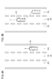
- FIG. 6A is a diagram illustrating a traveling state of the host vehicle 100 at a normal time during automatic driving.
- FIG. 6B is a diagram illustrating a traveling state of the host vehicle 100 with state change control.
- the double-track road 120 includes a traveling lane 122, a traveling lane 123, and an overtaking lane 124 in order from the left side.
- the current action plan is “lane keeping (constant speed running)” and the vehicle is traveling on the overtaking lane 124.
- the mode transition processing unit 54 notifies the action plan creation unit 52 that the lane change will be performed.
- the trajectory generation unit 58 generates a travel trajectory for changing the lane from the overtaking lane 124 to the travel lane 123 in accordance with the change of the action plan. Accordingly, the host vehicle 100 travels according to the travel track generated by the track generation unit 58 through the travel control by the travel control unit 60.
- the host vehicle 100 travels while maintaining the state of “constant speed traveling” after changing the lane along the track indicated by the dashed arrow as the state change control is executed. is doing.
- the vehicle control unit 70 when the vehicle control unit 70 performs lane change control of the host vehicle 100 as one form of the travel control, the host vehicle 100 is traveling on the double-track road 120 having the travel lanes 122 and 123 and the overtaking lane 124.
- the lane change control for changing the lane from the overtaking lane 124 to the traveling lane 123 may be performed as the state change control.
- the driver can start the manual operation while traveling on the travel lane 123 where there are many relatively low-speed vehicles.
- the travel control of the host vehicle 100 for securing the “safety margin” has been described, but the state change control is not limited to this form and purpose. Specifically, the state change control may be control for operating the control target 36 in order to prevent the “recognition ability” from being lowered by the driver.
- the vehicle control unit 70 may ensure the visibility of the driver by operating a wiper or a defroster as the control target 36.
- the device control unit 62 may reduce the amount of light entering the driver's field of view by operating a driver seat or blind device as the control target 36.
- the device control unit 62 may make the driver's vision easier to adapt to the external environment by lowering the brightness (illuminance) of the lighting device as the control target 36. [4] The device control unit 62 may make the driver's vision and hearing easier to adapt to the external environment by lowering the brightness and volume of the audio / video equipment as the control target 36.
- the influence determination unit 66 determines the degree of influence based on the intensity of the visual stimulus or the auditory stimulus given to the driver, and the vehicle control unit 70 determines the visual stimulus or the auditory stimulus as a relative. You may perform state change control weakened. As a result, the driver can perform manual operation under a state where external stimuli relating to visual or auditory sense are alleviated compared to before the execution of the state change control.
- FIG. 7 is a flowchart in an example different from FIG. As understood from this figure, this flowchart differs from FIG. 2 in that the execution order of steps S9 and S11 is reversed. In this case, the takeover request unit 68 continues the requested operation until accepting a takeover operation regardless of whether or not the influence degree has changed (step S11).
- the takeover request unit 68 may continue the requested operation even though the influence determining unit 66 determines that the high influence state has been eliminated before the takeover is completed. .
- the influence determining unit 66 determines that the high influence state has been eliminated before the takeover is completed.
- the vehicle control device 10 is a device that at least partially automatically performs the travel control of the host vehicle 100, and [1] travel environment acquisition that acquires the travel environment of the host vehicle 100 when performing the travel control. Based on the travel environment acquired by the unit 64 and [2], when the travel control is handed over from automatic to manual, or when it is predicted to take over, state change control for changing the state of the host vehicle 100 is performed.
- a vehicle control unit 70 is a device that at least partially automatically performs the travel control of the host vehicle 100, and [1] travel environment acquisition that acquires the travel environment of the host vehicle 100 when performing the travel control. Based on the travel environment acquired by the unit 64 and [2], when the travel control is handed over from automatic to manual, or when it is predicted to take over, state change control for changing the state of the host vehicle 100 is performed.
- a vehicle control unit 70 is a device that at least partially automatically performs the travel control of the host vehicle 100, and [1] travel environment acquisition that acquires the travel environment of the host vehicle 100 when performing the travel control. Based on the
- the vehicle control method using the vehicle control apparatus 10 is based on [1] acquisition step (S3) which acquires the traveling environment of the own vehicle 100 when performing traveling control, and [2] the acquired traveling environment.
- the traveling environment acquisition unit 64 may acquire the traveling environment at the predicted point 112 where the host vehicle 100 is predicted to travel in the future. Thereby, when it is going to take over in the prediction point 112, it can be grasped
- the vehicle control device 10 further includes an influence determination unit 66 that determines the degree of influence of the driving environment on the driver.
- an influence determination unit 66 that determines the degree of influence of the driving environment on the driver.
- the vehicle control unit 70 determines that the degree of influence is high, the driver easily performs manual driving. You may perform state change control which changes to a state. As a result, even if the degree of influence of the driving environment on the driver is high, the driver can perform manual driving under a state that is more adapted to the driving environment than before execution of the state change control.
Abstract
The vehicle control device (10) according to the present invention is a device that automatically controls the travel of a vehicle (100) at least partially, the vehicle control device comprising: a traveling environment acquisition unit (64) that acquires a traveling environment of the vehicle (100) when the travel control is performed; and a vehicle control unit (70) that performs state change control to change a state of the vehicle (100) on the basis of the traveling environment acquired by the traveling environment acquisition unit (64), when the travel control is transitioned from automatic to manual or when such transition is predicted.
Description
本発明は、自車両の走行制御を少なくとも部分的に自動で行う車両制御装置に関する。
The present invention relates to a vehicle control device that automatically and at least partially performs traveling control of the host vehicle.
従来から、自車両の走行制御を少なくとも部分的に自動で行う車両制御装置が知られている。例えば、運転モードを円滑に移行するためのタイミング制御技術が種々開発されている。
Conventionally, a vehicle control device that automatically performs at least partially the running control of the host vehicle is known. For example, various timing control techniques for smoothly shifting the operation mode have been developed.
特開平09-161196号公報(段落[0005]等)では、ドライバに対して運転モードの切り替え操作を促すことで、自動運転から手動運転への引き継ぎ(テイクオーバー)を要求する装置が提案されている。
Japanese Patent Application Laid-Open No. 09-161196 (paragraph [0005], etc.) proposes an apparatus that requests takeover from automatic operation to manual operation by prompting the driver to change the operation mode. Yes.
特開2015-175824号公報(段落[0025]、[0047]等)では、自動運転の中断理由が生じている「中断推奨」区間については、自動運転による走行が可能でないと判定された場合に自動運転を中断して手動運転により走行させる「中断」区間に設定するシステムが提案されている。中断推奨区間の一例として、車両走行時にカメラ又はセンサによる検出が難しい天候である区間が挙げられている。
In Japanese Patent Laying-Open No. 2015-175824 (paragraphs [0025], [0047], etc.), when it is determined that driving by automatic driving is not possible for the “recommended interruption” section in which the reason for interruption of automatic driving occurs. There has been proposed a system for setting an “interruption” section in which automatic operation is interrupted and the vehicle is driven by manual operation. As an example of the recommended interruption section, a section in which the weather is difficult to detect by a camera or a sensor when the vehicle is traveling is cited.
ところが、例えば、ドライバは、引き継ぎの要求動作に対して反射的に反応し、十分な準備が整わないまま切り替え操作を行ってしまう場合がある。特に、上記した天候である中断推奨区間を走行する場合、ドライバは、走行環境の認識に手間取って、運転を引き継いだ直後から円滑な運転操作を行うことができない可能性もある。
However, for example, the driver may react reflexively to the requested operation of takeover, and may perform a switching operation without sufficient preparation. In particular, when the vehicle travels in the recommended interruption section, which is the above-described weather, the driver may not be able to perform a smooth driving operation immediately after taking over the driving, taking time to recognize the driving environment.
本発明は上記した問題を解決するためになされたものであり、特定の走行環境下であっても、自動から手動への移行を円滑に遂行可能な車両制御装置を提供することを目的とする。
The present invention has been made to solve the above-described problems, and an object of the present invention is to provide a vehicle control device capable of smoothly performing a transition from automatic to manual even under a specific traveling environment. .
本発明に係る車両制御装置は、自車両の走行制御を少なくとも部分的に自動で行う装置であって、前記走行制御を行う際の前記自車両の走行環境を取得する走行環境取得部と、前記走行環境取得部により取得された前記走行環境に基づいて、前記走行制御を自動から手動に引き継ぐ際に、又は引き継ぐことが予測される際に、前記自車両の状態を変更する状態変更制御を行う車両制御部を備える。
A vehicle control device according to the present invention is a device that at least partially automatically performs travel control of the host vehicle, the travel environment acquiring unit acquiring the travel environment of the host vehicle when performing the travel control, Based on the travel environment acquired by the travel environment acquisition unit, state change control is performed to change the state of the host vehicle when the travel control is handed over from automatic to manual or when it is predicted to take over. A vehicle control unit is provided.
このように構成したので、走行制御を自動から手動に引き継ぐ際に、又は引き継ぐことが予測される際に、自車両の状態を走行環境に順応させることが可能になり、特定の走行環境下であっても自動運転から手動運転への移行を円滑に遂行することができる。
With this configuration, it is possible to adapt the state of the host vehicle to the driving environment when the driving control is handed over from automatic to manual, or when it is predicted to take over, under a specific driving environment. Even in such a case, the transition from automatic operation to manual operation can be performed smoothly.
また、前記走行環境取得部は、前記自車両が将来走行することが予測される予測地点における前記走行環境を取得してもよい。これにより、予測地点にて引き継ぎを行おうとする場合、状態変更制御の要否について事前に把握することができる。
Further, the traveling environment acquisition unit may acquire the traveling environment at a predicted point where the host vehicle is predicted to travel in the future. Thereby, when it is going to take over in a prediction point, it can grasp | ascertain beforehand about the necessity of state change control.
また、当該車両制御装置は、前記走行環境がドライバに与える影響度合いを判定する影響判定部をさらに備え、前記車両制御部は、前記影響判定部により前記影響度合いが高いと判定された場合、前記ドライバが手動運転を行い易い状態に変更する前記状態変更制御を行ってもよい。これにより、走行環境がドライバに与える影響度合いが高い場合であっても、ドライバは、状態変更制御の実行前と比べて走行環境により順応した状態下にて手動運転を行うことができる。
The vehicle control device further includes an influence determination unit that determines the degree of influence of the driving environment on the driver, and the vehicle control unit, when the influence determination unit determines that the influence degree is high, You may perform the said state change control which changes to the state in which a driver is easy to perform manual operation. As a result, even if the degree of influence of the driving environment on the driver is high, the driver can perform manual driving under a state that is more adapted to the driving environment than before execution of the state change control.
また、前記影響判定部は、前記ドライバに付与される視覚的刺激又は聴覚的刺激の強さに基づいて前記影響度合いを判定し、前記車両制御部は、前記視覚的刺激又は前記聴覚的刺激を相対的に弱める前記状態変更制御を行ってもよい。これにより、ドライバは、状態変更制御の実行前と比べて視覚又は聴覚に関する外的刺激が緩和されている状態下にて手動運転を行うことができる。
The influence determination unit determines the degree of influence based on the intensity of visual stimulus or auditory stimulus given to the driver, and the vehicle control unit determines the visual stimulus or the auditory stimulus. You may perform the said state change control to weaken relatively. As a result, the driver can perform manual operation under a state where external stimuli relating to visual or auditory sense are alleviated compared to before the execution of the state change control.
また、前記走行制御は、前記自車両の周辺の他車両に対する車間距離制御を含み、前記車両制御部は、前記他車両との車間距離を、前記状態変更制御が行われていない場合の車間距離制御における設定値と比べて大きい値に設定する前記状態変更制御を行ってもよい。これにより、ドライバは、自車両と他車両の間の相対位置の観点から、安全マージンを予備的に確保した状態下にて手動運転を行うことができる。
The travel control includes inter-vehicle distance control with respect to other vehicles in the vicinity of the host vehicle, and the vehicle control unit sets the inter-vehicle distance to the other vehicle as the inter-vehicle distance when the state change control is not performed. You may perform the said state change control set to a big value compared with the setting value in control. As a result, the driver can perform manual operation in a state in which a safety margin is secured in advance from the viewpoint of the relative position between the host vehicle and the other vehicle.
また、前記走行制御は、前記自車両の車速制御を含み、前記車両制御部は、前記状態変更制御として、前記自車両の速度を、前記状態変更制御が行われていない場合の車速制御における設定値と比べて低く設定する前記車速制御を行ってもよい。これにより、ドライバは、自車両と他車両の間の相対速度の観点から、安全マージンを予備的に確保した状態下にて手動運転を行うことができる。
The travel control includes vehicle speed control of the host vehicle, and the vehicle control unit sets the speed of the host vehicle in the vehicle speed control when the state change control is not performed as the state change control. You may perform the said vehicle speed control set low compared with a value. As a result, the driver can perform a manual operation in a state in which a safety margin is secured in advance from the viewpoint of the relative speed between the host vehicle and the other vehicle.
また、前記走行制御は、前記自車両の加速制御又は減速制御を含み、前記車両制御部は、前記状態変更制御として、前記自車両の加速度又は減速度を、前記状態変更制御が行われていない場合の加速制御又は減速制御における設定値と比べて低く設定する前記加速制御又は前記減速制御を行ってもよい。これにより、ドライバは、自車両の加速動作又は減速動作の観点から、安全マージンを予備的に確保した状態下にて手動運転を行うことができる。
The travel control includes acceleration control or deceleration control of the host vehicle, and the vehicle control unit does not perform acceleration or deceleration of the host vehicle as the state change control. The acceleration control or the deceleration control that is set lower than the set value in the acceleration control or deceleration control in the case may be performed. As a result, the driver can perform manual operation in a state in which a safety margin is secured in advance from the viewpoint of the acceleration operation or the deceleration operation of the host vehicle.
また、前記走行制御は、前記自車両のレーン変更制御を含み、前記車両制御部は、走行レーン及び追い越しレーンを有する複線道路を前記自車両が走行中である場合、前記状態変更制御として、前記追い越しレーンから前記走行レーンに変更する前記レーン変更制御を行ってもよい。これにより、ドライバは、相対的に低速の車両が多い走行レーンを走行しながら手動運転を行うことができる。
Further, the travel control includes lane change control of the host vehicle, and the vehicle control unit, as the state change control, when the host vehicle is traveling on a double-track road having a travel lane and an overtaking lane, The lane change control for changing from an overtaking lane to the traveling lane may be performed. As a result, the driver can perform manual driving while traveling on a traveling lane where there are many relatively low-speed vehicles.
また、当該車両制御装置は、前記自車両のドライバに対して手動運転への引き継ぎを要求する要求動作を行う引継要求部をさらに備え、前記車両制御部は、前記引継要求部が前記要求動作を行う前に前記状態変更制御を行ってもよい。これにより、ドライバは、要求動作中のどのタイミングで引き継いだとしても、自車両の状態が変更されている状態下にて手動運転を開始することができる。
The vehicle control device further includes a takeover request unit that performs a request operation for requesting the driver of the host vehicle to take over to manual operation, and the vehicle control unit includes the takeover request unit that performs the request operation. The state change control may be performed before it is performed. As a result, the driver can start manual operation under a state in which the state of the host vehicle is changed regardless of the timing at which the driver takes over during the requested operation.
また、前記車両制御部は、前記自車両が前記予測地点を通過したにもかかわらず、前記引継要求部が前記要求動作をまだ行っていない場合に、前記状態変更制御による変更を解除してもよい。これにより、予測地点での引き継ぎの必要が無くなったとして、自動による走行制御に適した状態に戻すことができる。
In addition, the vehicle control unit may cancel the change by the state change control when the takeover request unit has not yet performed the request operation even though the host vehicle has passed the predicted point. Good. As a result, it is possible to return to a state suitable for automatic travel control, assuming that there is no need to take over at the predicted point.
また、前記車両制御部は、前記状態変更制御の開始時点から、前記自車両が所定距離を走行し及び/又は所定時間が経過したにもかかわらず、前記引継要求部が前記要求動作をまだ行っていない場合に、前記状態変更制御による変更を解除してもよい。これにより、予測していた距離範囲内又は時間範囲内での引き継ぎの必要が無くなったとして、自動による走行制御に適した状態に戻すことができる。
In addition, the vehicle control unit may perform the request operation by the takeover request unit even though the host vehicle has traveled a predetermined distance and / or a predetermined time has elapsed since the start of the state change control. If not, the change by the state change control may be canceled. As a result, it is possible to return to a state suitable for automatic travel control, assuming that it is no longer necessary to take over within the predicted distance range or time range.
また、当該車両制御装置は、前記自車両のドライバに対して手動運転への引き継ぎを要求する要求動作を行う引継要求部をさらに備え、前記引継要求部は、前記引き継ぎが完了する前に、前記影響判定部により前記影響度合いの高い状態が解消された旨の判定がなされた場合、前記要求動作を中止してもよい。これにより、影響度合いが事後的に低下した場合において自動運転をそのまま継続可能となり、運転の利便性が向上する。
In addition, the vehicle control device further includes a takeover request unit that performs a request operation for requesting the driver of the host vehicle to take over to manual operation, and the takeover request unit, before the takeover is completed, When the influence determining unit determines that the state with the high degree of influence has been eliminated, the requested operation may be stopped. As a result, when the degree of influence is subsequently reduced, automatic driving can be continued as it is, and the convenience of driving is improved.
また、当該車両制御装置は、前記自車両のドライバに対して手動運転への引き継ぎを要求する要求動作を行う引継要求部をさらに備え、前記引継要求部は、前記引き継ぎが完了する前に、前記影響判定部により前記影響度合いの高い状態が解消された旨の判定がなされたにもかかわらず、前記要求動作を継続してもよい。これにより、短時間の中で影響度合いが大きく変動した場合に断続的な要求動作が行われるのを防げるため、ドライバに違和感を与えなくて済む。
In addition, the vehicle control device further includes a takeover request unit that performs a request operation for requesting the driver of the host vehicle to take over to manual operation, and the takeover request unit, before the takeover is completed, The requested operation may be continued even though the influence determining unit determines that the high influence state has been eliminated. As a result, it is possible to prevent the intermittent requested operation from being performed when the degree of influence fluctuates greatly within a short period of time, so that the driver does not feel uncomfortable.
本発明に係る車両制御装置によれば、特定の走行環境下であっても、自動運転から手動運転への移行を円滑に遂行することができる。
The vehicle control apparatus according to the present invention can smoothly perform the transition from automatic driving to manual driving even under a specific traveling environment.
以下、本発明に係る車両制御装置について好適な実施形態を挙げ、添付の図面を参照しながら説明する。
Hereinafter, preferred embodiments of the vehicle control device according to the present invention will be described with reference to the accompanying drawings.
[車両制御装置10の構成]
<全体構成>
図1は、本発明の一実施形態に係る車両制御装置10の構成を示すブロック図である。車両制御装置10は、車両(図3等の自車両100)に組み込まれており、且つ、自動又は手動により車両の走行制御を行う。この「自動運転」は、車両の走行制御をすべて自動で行う「完全自動運転」のみならず、走行制御を部分的に自動で行う「部分自動運転」を含む概念である。 [Configuration of Vehicle Control Device 10]
<Overall configuration>
FIG. 1 is a block diagram showing a configuration of avehicle control device 10 according to an embodiment of the present invention. The vehicle control device 10 is incorporated in a vehicle (the own vehicle 100 shown in FIG. 3 and the like), and performs traveling control of the vehicle automatically or manually. This “automatic driving” is a concept that includes not only “fully automatic driving” in which all driving control of a vehicle is automatically performed, but also “partial automatic driving” in which driving control is partially performed automatically.
<全体構成>
図1は、本発明の一実施形態に係る車両制御装置10の構成を示すブロック図である。車両制御装置10は、車両(図3等の自車両100)に組み込まれており、且つ、自動又は手動により車両の走行制御を行う。この「自動運転」は、車両の走行制御をすべて自動で行う「完全自動運転」のみならず、走行制御を部分的に自動で行う「部分自動運転」を含む概念である。 [Configuration of Vehicle Control Device 10]
<Overall configuration>
FIG. 1 is a block diagram showing a configuration of a
車両制御装置10は、基本的には、入力系装置群と、制御システム12と、出力系装置群とから構成される。入力系装置群及び出力系装置群をなす各々の装置は、制御システム12に通信線を介して接続されている。
The vehicle control device 10 basically includes an input system device group, a control system 12, and an output system device group. Each device forming the input system device group and the output system device group is connected to the control system 12 via a communication line.
入力系装置群は、外界センサ14と、通信装置16と、ナビゲーション装置18と、車両センサ20と、自動運転スイッチ22と、操作デバイス24に接続された操作検出センサ26と、を備える。
The input system device group includes an external sensor 14, a communication device 16, a navigation device 18, a vehicle sensor 20, an automatic operation switch 22, and an operation detection sensor 26 connected to the operation device 24.
出力系装置群は、図示しない車輪を駆動する駆動力装置28と、当該車輪を操舵する操舵装置30と、当該車輪を制動する制動装置32と、主に視覚・聴覚を通じて運転者に報知する報知装置34と、後述する状態変更制御における制御対象36と、を備える。
The output system device group includes a driving force device 28 that drives a wheel (not shown), a steering device 30 that steers the wheel, a braking device 32 that brakes the wheel, and a notification that informs the driver mainly through vision and hearing. The apparatus 34 and the control object 36 in the state change control mentioned later are provided.
<入力系装置群の具体的構成>
外界センサ14は、車両の外界状態を示す情報(以下、外界情報)を取得し、当該外界情報を制御システム12に出力する。外界センサ14は、具体的には、複数のカメラ38と、複数のレーダ39と、複数のLIDAR40(Light Detection and Ranging;光検出と測距/Laser Imaging Detection and Ranging;レーザ画像検出と測距)を含んで構成される。 <Specific configuration of input device group>
Theoutside world sensor 14 acquires information indicating the outside world state of the vehicle (hereinafter, outside world information) and outputs the outside world information to the control system 12. Specifically, the external sensor 14 includes a plurality of cameras 38, a plurality of radars 39, and a plurality of LIDARs 40 (Light Detection and Ranging; Laser Imaging Detection and Ranging). It is comprised including.
外界センサ14は、車両の外界状態を示す情報(以下、外界情報)を取得し、当該外界情報を制御システム12に出力する。外界センサ14は、具体的には、複数のカメラ38と、複数のレーダ39と、複数のLIDAR40(Light Detection and Ranging;光検出と測距/Laser Imaging Detection and Ranging;レーザ画像検出と測距)を含んで構成される。 <Specific configuration of input device group>
The
通信装置16は、路側機、他の車両、及びサーバを含む外部装置と通信可能に構成されており、例えば、交通機器に関わる情報、他の車両に関わる情報、プローブ情報又は最新の地図情報44を送受信する。この地図情報44は、記憶装置42の所定メモリ領域内に、或いはナビゲーション装置18に記憶される。
The communication device 16 is configured to be able to communicate with roadside units, other vehicles, and external devices including a server. For example, information related to traffic equipment, information related to other vehicles, probe information, or the latest map information 44. Send and receive. The map information 44 is stored in a predetermined memory area of the storage device 42 or in the navigation device 18.
ナビゲーション装置18は、車両の現在位置を検出可能な衛星測位装置と、ユーザインタフェース(例えば、タッチパネル式のディスプレイ、スピーカ及びマイク)を含んで構成される。ナビゲーション装置18は、車両の現在位置又はユーザによる指定位置に基づいて、指定した目的地までの経路を算出し、制御システム12に出力する。ナビゲーション装置18により算出された経路は、記憶装置42の所定メモリ領域内に、経路情報46として記憶される。
The navigation device 18 includes a satellite positioning device that can detect the current position of the vehicle and a user interface (for example, a touch panel display, a speaker, and a microphone). The navigation device 18 calculates a route to the designated destination based on the current position of the vehicle or the position designated by the user, and outputs the route to the control system 12. The route calculated by the navigation device 18 is stored as route information 46 in a predetermined memory area of the storage device 42.
車両センサ20は、車両の速度V(車速)を検出する速度センサ、加速度を検出する加速度センサ、横Gを検出する横Gセンサ、垂直軸周りの角速度を検出するヨーレートセンサ、向き・方位を検出する方位センサ、勾配を検出する勾配センサを含み、各々のセンサからの検出信号を制御システム12に出力する。これらの検出信号は、記憶装置42の所定メモリ領域内に、自車情報48として記憶される。
The vehicle sensor 20 is a speed sensor that detects a vehicle speed V (vehicle speed), an acceleration sensor that detects acceleration, a lateral G sensor that detects lateral G, a yaw rate sensor that detects angular velocity around a vertical axis, and a direction / orientation. A azimuth sensor that detects the gradient and a gradient sensor that detects the gradient, and outputs a detection signal from each sensor to the control system 12. These detection signals are stored as own vehicle information 48 in a predetermined memory area of the storage device 42.
自動運転スイッチ22は、例えば、インストルメントパネルに設けられた押しボタンスイッチである。自動運転スイッチ22は、ドライバを含むユーザのマニュアル操作により、複数の運転モードを切り替え可能に構成される。
The automatic operation switch 22 is, for example, a push button switch provided on the instrument panel. The automatic operation switch 22 is configured so that a plurality of operation modes can be switched by a manual operation of a user including a driver.
操作デバイス24は、アクセルペダル、ステアリングホイール、ブレーキペダル、シフトレバー、及び方向指示レバーを含んで構成される。操作デバイス24には、ドライバによる操作の有無や操作量、操作位置を検出する操作検出センサ26が取り付けられている。
The operation device 24 includes an accelerator pedal, a steering wheel, a brake pedal, a shift lever, and a direction indicating lever. The operation device 24 is provided with an operation detection sensor 26 that detects the presence / absence of the operation by the driver, the operation amount, and the operation position.
操作検出センサ26は、検出結果としてアクセル踏込量(アクセル開度)、ステアリング操作量(操舵量)、ブレーキ踏込量、シフト位置、右左折方向等を走行制御部60に出力する。
The operation detection sensor 26 outputs the accelerator depression amount (accelerator opening), the steering operation amount (steering amount), the brake depression amount, the shift position, the right / left turn direction, and the like as detection results to the travel control unit 60.
<出力系装置群の具体的構成>
駆動力装置28は、駆動力ECU(電子制御装置;Electronic Control Unit)と、エンジン・駆動モータを含む駆動源から構成される。駆動力装置28は、走行制御部60から入力される走行制御値に従って車両の走行駆動力(トルク)を生成し、トランスミッションを介して、或いは直接的に車輪に伝達する。 <Specific configuration of output system group>
The driving force device 28 includes a driving force ECU (Electronic Control Unit) and a driving source including an engine and a driving motor. The driving force device 28 generates a traveling driving force (torque) of the vehicle according to the traveling control value input from the travelingcontrol unit 60 and transmits it to the wheels via the transmission or directly.
駆動力装置28は、駆動力ECU(電子制御装置;Electronic Control Unit)と、エンジン・駆動モータを含む駆動源から構成される。駆動力装置28は、走行制御部60から入力される走行制御値に従って車両の走行駆動力(トルク)を生成し、トランスミッションを介して、或いは直接的に車輪に伝達する。 <Specific configuration of output system group>
The driving force device 28 includes a driving force ECU (Electronic Control Unit) and a driving source including an engine and a driving motor. The driving force device 28 generates a traveling driving force (torque) of the vehicle according to the traveling control value input from the traveling
操舵装置30は、EPS(電動パワーステアリングシステム)ECUと、EPS装置とから構成される。操舵装置30は、走行制御部60から入力される走行制御値に従って車輪(操舵輪)の向きを変更する。
The steering device 30 includes an EPS (electric power steering system) ECU and an EPS device. The steering device 30 changes the direction of the wheels (steering wheels) according to the travel control value input from the travel control unit 60.
制動装置32は、例えば、油圧式ブレーキを併用する電動サーボブレーキであって、ブレーキECUと、ブレーキアクチュエータとから構成される。制動装置32は、走行制御部60から入力される走行制御値に従って車輪を制動する。
The braking device 32 is, for example, an electric servo brake that also uses a hydraulic brake, and includes a brake ECU and a brake actuator. The braking device 32 brakes the wheel according to the travel control value input from the travel control unit 60.
報知装置34は、報知ECUと、表示装置と、音響装置とから構成される。報知装置34は、制御システム12(具体的には、モード移行処理部54)から出力される報知指令に応じて、自動運転又は手動運転に関わる報知動作(後述するTORを含む)を行う。
The notification device 34 includes a notification ECU, a display device, and an acoustic device. The notification device 34 performs a notification operation (including TOR described later) related to automatic driving or manual driving in response to a notification command output from the control system 12 (specifically, the mode transition processing unit 54).
制御対象36は、後述する状態変更制御による動作対象物であり、例えば、ワイパ、デフロスタ(デフォッガ)、照明装置、ブラインド装置、又はドライバシートである。また、制御対象36は、車両制御装置10に含まれる別の構成(例えば、ナビゲーション装置18)と兼ねてもよい。
The control target 36 is an operation target by state change control described later, and is, for example, a wiper, a defroster (defogger), a lighting device, a blind device, or a driver seat. Further, the control target 36 may also serve as another configuration (for example, the navigation device 18) included in the vehicle control device 10.
<運転モード>
ここで、自動運転スイッチ22が押される度に、「自動運転モード」と「手動運転モード」(非自動運転モード)が順次切り替わるように設定されている。これに代わって、ドライバの意思確認を確実にするため、例えば、2度押しで手動運転モードから自動運転モードに切り替わり、1度押しで自動運転モードから手動運転モードに切り替わるように設定することもできる。 <Operation mode>
Here, each time theautomatic operation switch 22 is pressed, the “automatic operation mode” and the “manual operation mode” (non-automatic operation mode) are sequentially switched. Instead of this, in order to ensure the driver's intention confirmation, for example, it is possible to switch from manual operation mode to automatic operation mode by pressing twice to switch from automatic operation mode to manual operation mode by pressing once. it can.
ここで、自動運転スイッチ22が押される度に、「自動運転モード」と「手動運転モード」(非自動運転モード)が順次切り替わるように設定されている。これに代わって、ドライバの意思確認を確実にするため、例えば、2度押しで手動運転モードから自動運転モードに切り替わり、1度押しで自動運転モードから手動運転モードに切り替わるように設定することもできる。 <Operation mode>
Here, each time the
自動運転モードは、ドライバが、操作デバイス24(具体的には、アクセルペダル、ステアリングホイール及びブレーキペダル)の操作を行わない状態で、車両が制御システム12による制御下に走行する運転モードである。換言すれば、自動運転モードは、制御システム12が、逐次作成される行動計画に従って、駆動力装置28、操舵装置30、及び制動装置32の一部又は全部を制御する運転モードである。
The automatic operation mode is an operation mode in which the vehicle travels under the control of the control system 12 while the driver does not operate the operation device 24 (specifically, the accelerator pedal, the steering wheel, and the brake pedal). In other words, the automatic operation mode is an operation mode in which the control system 12 controls a part or all of the driving force device 28, the steering device 30, and the braking device 32 in accordance with the action plan that is sequentially generated.
なお、ドライバが、自動運転モードの実行中に操作デバイス24を用いた所定の操作を行うと、自動運転モードが自動的に解除されると共に、運転の自動化レベルが相対的に低い運転モード(手動運転モードを含む)に切り替わる。以下、自動運転から手動運転へ移行させるために、ドライバが自動運転スイッチ22又は操作デバイス24を操作することを「テイクオーバー操作」ともいう。
Note that if the driver performs a predetermined operation using the operation device 24 during the execution of the automatic operation mode, the automatic operation mode is automatically canceled and the operation mode (manual operation) with a relatively low level of operation automation is performed. (Including operation mode). Hereinafter, the operation of the automatic operation switch 22 or the operation device 24 by the driver in order to shift from the automatic operation to the manual operation is also referred to as “takeover operation”.
<制御システム12の構成>
制御システム12は、1つ又は複数のECUにより構成され、上記した記憶装置42の他、各種機能実現部を備える。この実施形態では、機能実現部は、1つ又は複数のCPU(Central Processing Unit)が、非一過性の記憶装置42に記憶されているプログラムを実行することにより機能が実現されるソフトウエア機能部である。これに代わって、機能実現部は、FPGA(Field-Programmable Gate Array)等の集積回路からなるハードウエア機能部であってもよい。 <Configuration ofcontrol system 12>
Thecontrol system 12 includes one or a plurality of ECUs, and includes various function implementation units in addition to the storage device 42 described above. In this embodiment, the function realizing unit is a software function in which a function is realized by one or more CPUs (Central Processing Units) executing a program stored in the non-transitory storage device 42. Part. Alternatively, the function implementation unit may be a hardware function unit including an integrated circuit such as an FPGA (Field-Programmable Gate Array).
制御システム12は、1つ又は複数のECUにより構成され、上記した記憶装置42の他、各種機能実現部を備える。この実施形態では、機能実現部は、1つ又は複数のCPU(Central Processing Unit)が、非一過性の記憶装置42に記憶されているプログラムを実行することにより機能が実現されるソフトウエア機能部である。これに代わって、機能実現部は、FPGA(Field-Programmable Gate Array)等の集積回路からなるハードウエア機能部であってもよい。 <Configuration of
The
制御システム12は、記憶装置42及び走行制御部60の他、外界認識部50と、行動計画作成部52と、モード移行処理部54と、情報取得部56と、軌道生成部58と、装置制御部62と、を含んで構成される。
In addition to the storage device 42 and the travel control unit 60, the control system 12 includes an external environment recognition unit 50, an action plan creation unit 52, a mode transition processing unit 54, an information acquisition unit 56, a trajectory generation unit 58, and device control. Part 62.
外界認識部50は、入力系装置群により入力された各種情報(例えば、外界センサ14からの外界情報)を用いて、車両の両側にあるレーンマーク(白線)を認識し、停止線・信号機の位置情報、又は走行可能領域を含む「静的」な外界認識情報を生成する。また、外界認識部50は、入力された各種情報を用いて、駐停車車両等の障害物、人・他車両等の交通参加者、又は信号機の灯色を含む「動的」な外界認識情報を生成する。
The outside world recognition unit 50 recognizes lane marks (white lines) on both sides of the vehicle using various information (for example, outside world information from the outside world sensor 14) input by the input system device group, “Static” external environment recognition information including position information or a travelable area is generated. In addition, the external environment recognition unit 50 uses the various input information to provide “dynamic” external environment recognition information including obstacles such as parked and stopped vehicles, traffic participants such as people and other vehicles, or traffic lights. Is generated.
行動計画作成部52は、外界認識部50による認識結果に基づいて走行区間毎の行動計画(イベントの時系列)を作成し、必要に応じて行動計画を更新する。イベントの種類として、例えば、減速、加速、分岐、合流、レーンキープ、レーン変更、追い越しが挙げられる。ここで、「減速」「加速」は、車両を減速又は加速させるイベントである。「分岐」「合流」は、分岐地点又は合流地点にて車両を円滑に走行させるイベントである。「レーン変更」は、車両の走行レーンを変更させるイベントである。「追い越し」は、車両に前走車両を追い越させるイベントである。
The action plan creation unit 52 creates an action plan (time series of events) for each traveling section based on the recognition result by the external recognition unit 50, and updates the action plan as necessary. Examples of the event type include deceleration, acceleration, branching, merging, lane keeping, lane change, and overtaking. Here, “deceleration” and “acceleration” are events that decelerate or accelerate the vehicle. “Branch” and “Join” are events that allow a vehicle to smoothly travel at a branch point or a merge point. “Lane change” is an event for changing the traveling lane of a vehicle. “Overtaking” is an event in which a vehicle overtakes the preceding vehicle.
また、「レーンキープ」は、走行レーンを逸脱しないように車両を走行させるイベントであり、走行態様との組み合わせによって細分化される。走行態様として、具体的には、定速走行、追従走行、減速走行、カーブ走行、或いは障害物回避走行が含まれる。
Also, the “lane keep” is an event for driving the vehicle so as not to deviate from the driving lane, and is subdivided according to the combination with the driving mode. Specifically, the traveling mode includes constant speed traveling, following traveling, deceleration traveling, curve traveling, or obstacle avoidance traveling.
モード移行処理部54は、運転モードの移行処理を行うと共に、行動計画作成部52又は装置制御部62に向けて信号を出力する。具体的には、モード移行処理部54は、走行環境取得部64、影響判定部66、及び引継要求部68として機能する。
The mode transition processing unit 54 performs the operation mode transition processing and outputs a signal to the action plan creation unit 52 or the device control unit 62. Specifically, the mode transition processing unit 54 functions as a traveling environment acquisition unit 64, an influence determination unit 66, and a takeover request unit 68.
情報取得部56は、走行環境がドライバに与える影響の判定処理に必要な情報を取得する。必要な情報には、具体例として、時間情報(例えば、現在時刻・時間帯・到着予想時刻)、地理情報(例えば、緯度・経度・標高・地形・高低差)、天候情報(例えば、天気・気温・湿度・予報情報)が挙げられる。
The information acquisition unit 56 acquires information necessary for determining the influence of the driving environment on the driver. Specific examples of necessary information include time information (for example, current time / time zone / estimated arrival time), geographical information (for example, latitude / longitude / altitude / terrain / level difference), weather information (for example, weather / Temperature, humidity, forecast information).
軌道生成部58は、記憶装置42から読み出した地図情報44、経路情報46及び自車情報48を用いて、行動計画作成部52により作成された行動計画に従う走行軌道(目標挙動の時系列)を生成する。この走行軌道は、具体的には、位置、姿勢角、速度、加速度、曲率、ヨーレート、操舵角をデータ単位とする時系列データセットである。
The track generation unit 58 uses the map information 44, the route information 46, and the vehicle information 48 read from the storage device 42 to generate a travel track (time series of target behavior) according to the action plan created by the action plan creation unit 52. Generate. More specifically, the traveling track is a time series data set in which the position, posture angle, speed, acceleration, curvature, yaw rate, and steering angle are data units.
走行制御部60は、軌道生成部58により生成された走行軌道(目標挙動の時系列)に従って、車両を走行制御するための各々の走行制御値を決定する。そして、走行制御部60は、得られた各々の走行制御値を、駆動力装置28、操舵装置30、及び制動装置32に出力する。
The traveling control unit 60 determines each traveling control value for traveling control of the vehicle according to the traveling track (time series of the target behavior) generated by the track generating unit 58. Then, the traveling control unit 60 outputs the obtained traveling control values to the driving force device 28, the steering device 30, and the braking device 32.
装置制御部62は、モード移行処理部54からの指令に応じて、報知装置34又は制御対象36を駆動制御する。以下、走行制御部60及び装置制御部62を総称して「車両制御部70」という場合がある。
The device control unit 62 drives and controls the notification device 34 or the control target 36 in accordance with a command from the mode transition processing unit 54. Hereinafter, the traveling control unit 60 and the device control unit 62 may be collectively referred to as a “vehicle control unit 70”.
[車両制御装置10の動作]
<全体の流れ>
本実施形態における車両制御装置10は、以上のように構成される。続いて、車両制御装置10の動作(特に、運転モードの切り替え動作)について、図2のフローチャートを主に参照しながら説明する。ここでは、車両制御装置10を搭載した自車両100が、自動又は手動により走行する場合を想定する。 [Operation of Vehicle Control Device 10]
<Overall flow>
Thevehicle control device 10 in the present embodiment is configured as described above. Next, the operation of the vehicle control device 10 (particularly, the operation mode switching operation) will be described with reference mainly to the flowchart of FIG. Here, it is assumed that the host vehicle 100 equipped with the vehicle control device 10 travels automatically or manually.
<全体の流れ>
本実施形態における車両制御装置10は、以上のように構成される。続いて、車両制御装置10の動作(特に、運転モードの切り替え動作)について、図2のフローチャートを主に参照しながら説明する。ここでは、車両制御装置10を搭載した自車両100が、自動又は手動により走行する場合を想定する。 [Operation of Vehicle Control Device 10]
<Overall flow>
The
ステップS1において、モード移行処理部54は、自動運転モード(自動運転スイッチ22)が「オン」であるか否かを判定する。「オン」ではない(「オフ」である)と判定された場合(ステップS1:NO)、車両制御装置10は、手動による自車両100の走行制御、つまり手動運転を継続する(ステップS2)。一方、「オン」であると判定された場合(ステップS1:YES)、ステップS3に進む。
In step S1, the mode transition processing unit 54 determines whether or not the automatic operation mode (automatic operation switch 22) is “ON”. When it is determined that it is not “on” (“off”) (step S1: NO), the vehicle control device 10 continues the travel control of the host vehicle 100 by hand, that is, manual operation (step S2). On the other hand, when it determines with it being "on" (step S1: YES), it progresses to step S3.
ステップS3において、走行環境取得部64は、将来走行することが予測される任意の地点(以下、予測地点112;図3)における自車両100の走行環境を取得する。この走行環境には、外界認識部50による直近の認識結果、又は、情報取得部56からの取得情報(例えば、上記した時間情報・地理情報・天候情報)が含まれる。
In step S3, the traveling environment acquisition unit 64 acquires the traveling environment of the host vehicle 100 at an arbitrary point predicted to travel in the future (hereinafter, predicted point 112; FIG. 3). This travel environment includes the latest recognition result by the external environment recognition unit 50 or the acquisition information from the information acquisition unit 56 (for example, the time information, geographical information, and weather information described above).
ステップS4において、影響判定部66は、ステップS3で取得された走行環境がドライバに与える影響度合いを判定する。例えば、影響判定部66は、特定の環境条件を満たす場合に影響度合いが高く、満たさない場合に影響度合いが低いと判定してもよい。ここで、「特定の環境条件」とは、例えば、自然環境(外的刺激)の動的・時間的な変化に伴って、自動による走行制御の継続が困難であると推認される条件(具体例としては、逆光・濃霧・路面凍結の発生条件)である。
In step S4, the influence determination unit 66 determines the degree of influence the driving environment acquired in step S3 has on the driver. For example, the influence determination unit 66 may determine that the degree of influence is high when a specific environmental condition is satisfied, and that the degree of influence is low when the specific environmental condition is not satisfied. Here, the “specific environmental condition” is, for example, a condition (specifically, it is assumed that it is difficult to continue automatic driving control with a dynamic / temporal change of the natural environment (external stimulus). Examples include conditions of backlight, dense fog, and road surface freezing.
図3に示すように、自車両100は、直線状の走行レーン102を走行している場合を想定する。走行レーン102と対向レーン104は、3本のレーンマーク106、107、108により区画されている。レーンマーク106、108は連続線状であり、レーンマーク107は破線状である。
As shown in FIG. 3, it is assumed that the host vehicle 100 is traveling on a straight traveling lane 102. The traveling lane 102 and the opposite lane 104 are partitioned by three lane marks 106, 107, and 108. The lane marks 106 and 108 are continuous lines, and the lane mark 107 is a broken line.
本図は、自動車が左側走行することを取り極められている国の道路を示しており、他車両110は、自車両100に先行して同一の走行レーン102を走行している。ここでは、自車両100及び他車両110はそれぞれ、西南西(WSW)の方位に向かって走行している。
This drawing shows a road in a country where it is determined that the automobile is traveling on the left side, and the other vehicle 110 is traveling on the same traveling lane 102 prior to the host vehicle 100. Here, each of the host vehicle 100 and the other vehicle 110 is traveling toward the west-southwest (WSW) direction.
以下、特定の環境条件が「逆光状態であること」を例に説明する。影響判定部66は、地図情報44、経路情報46及び自車情報48を用いて、[1]予測地点112、[2]予測地点112に到達した自車両100の走行方向、をそれぞれ予測する。この予測地点112は、要求動作(後述するTOR)又は手動への引き継ぎが将来的に行われると予測された、走行予定経路上の位置である。
Hereinafter, an example in which a specific environmental condition is “backlit state” will be described. The influence determination unit 66 uses the map information 44, the route information 46, and the own vehicle information 48 to predict [1] the predicted point 112 and [2] the traveling direction of the own vehicle 100 that has reached the predicted point 112, respectively. The predicted point 112 is a position on the planned travel route where the requested operation (TOR described later) or manual handover is predicted to be performed in the future.
また、影響判定部66は、時間情報(例えば、年月日、ローカル時刻)及び地理情報(例えば、緯度)を用いて、[3]外光(太陽光)の入射方向、[4]外光の強さ・照度、をそれぞれ予測する。
Moreover, the influence determination part 66 uses [3] incident direction of external light (sunlight), [4] external light, using time information (for example, date, local time) and geographical information (for example, latitude). Predicts the intensity and illuminance of each.
そして、影響判定部66は、自車両100の走行方向(例えば、西南西)と、外光入射方向(例えば、西日に相当する「東北東」)の間の角度差が180度に等しいかこれに近い場合、「逆光状態」であると判定する。一方、影響判定部66は、この角度差が180度とは有意に異なる場合には「逆光状態」ではないと判定する。
Then, the influence determination unit 66 determines whether the angle difference between the traveling direction of the host vehicle 100 (for example, west-southwest) and the external light incident direction (for example, “east-northeast” corresponding to the west day) is equal to 180 degrees. If it is close to, it is determined to be in the “backlight state”. On the other hand, when the angle difference is significantly different from 180 degrees, the influence determination unit 66 determines that the state is not “backlit state”.
なお、判定処理に供される環境条件は上記した条件に限られず、他の制約条件を組み合わせてもよい。制約条件の具体例として、[1]天候が「晴れ」であること、[2]実測気温又は予想気温が閾値よりも高いこと、[3]予測地点112の周辺114に背の高い構造物が存在しないこと、[4]予測地点112が上り坂であって勾配が閾値よりも大きいこと、[5]予測地点112が高架下又はトンネルの出口に位置すること、等が挙げられる。
Note that the environmental conditions used for the determination process are not limited to the above-described conditions, and other constraint conditions may be combined. As specific examples of the constraint conditions, [1] the weather is “sunny”, [2] the measured or predicted temperature is higher than the threshold, and [3] a tall structure around the predicted point 112 is 114. It is not present, [4] the predicted point 112 is an uphill, and the gradient is larger than a threshold, and [5] the predicted point 112 is located under an overpass or at the exit of a tunnel.
また、車体前方に設けられた光検出装置(具体的には、カメラ38、図示しない照度計)を用いて外光の強さを測定し、この測定結果を判定処理に反映させてもよい。例えば、影響判定部66は、カメラ38により得られた撮像信号を解析し、サチュレーション、フレア、ゴースト又はスミアが発生した場合に「逆光状態」であると判定してもよい。
Alternatively, the intensity of external light may be measured using a light detection device (specifically, camera 38, illuminance meter not shown) provided in front of the vehicle body, and the measurement result may be reflected in the determination process. For example, the influence determination unit 66 may analyze the imaging signal obtained by the camera 38 and determine that the state is the “backlight state” when saturation, flare, ghost, or smear occurs.
また、影響判定部66は、上記した判定手法(条件成否)に代わって、定量化・数値化した影響度合いと閾値の間の大小関係による閾値判定を行ってもよい。走行環境が数値(観測値又は予測値)で示される場合、例えば、気温、湿度、日射量、風速、雨量、又は霧水量に関して、これらの値を用いて直接的に閾値判定を行ってもよい。或いは、影響判定部66は、所定の評価基準に従って各種情報(条件又は数値)を得点化し、各々の得点の合計をもって影響度合いを算出してもよい。
In addition, the influence determination unit 66 may perform threshold determination based on the magnitude relationship between the quantified and quantified influence degree and the threshold instead of the above-described determination method (condition success / failure). When the driving environment is indicated by a numerical value (observed value or predicted value), for example, regarding the temperature, humidity, solar radiation amount, wind speed, rain amount, or fog water amount, the threshold value determination may be performed directly using these values. . Alternatively, the influence determination unit 66 may score various information (conditions or numerical values) according to a predetermined evaluation criterion, and calculate the degree of influence using the total of the respective scores.
図2に戻って、ドライバに与える影響度合いが高くないと判定された場合(ステップS4:NO)、車両制御装置10は、自動による自車両100の走行制御、つまり自動運転を継続する(ステップS5)。一方、影響度が高いと判定された場合(ステップS4:YES)、ステップS6に進む。
Returning to FIG. 2, when it is determined that the degree of influence on the driver is not high (step S4: NO), the vehicle control device 10 continues the automatic travel control of the host vehicle 100, that is, automatic driving (step S5). ). On the other hand, when it is determined that the degree of influence is high (step S4: YES), the process proceeds to step S6.
ステップS6において、車両制御部70(具体的には、走行制御部60)は、駆動力装置28、操舵装置30、制動装置32又は制御対象36に対して状態変更制御を行う。ここで、「状態変更制御」とは、走行制御を自動から手動に引き継ぐ際に、又は引き継ぐことが予測される際に、自車両100の状態を変更する制御であり、より具体的には、ドライバが手動運転を行い易い運転環境を構築するための制御(換言すれば、おもてなし制御)である。
In step S6, the vehicle control unit 70 (specifically, the travel control unit 60) performs state change control on the driving force device 28, the steering device 30, the braking device 32, or the control target 36. Here, the “state change control” is control that changes the state of the host vehicle 100 when the travel control is handed over from automatic to manual, or when it is predicted to take over, and more specifically, This is control (in other words, hospitality control) for constructing an operating environment in which the driver can easily perform manual operation.
ここで、車両制御部70は、引継要求部68が要求動作(後述するステップS8)を行う前に状態変更制御を行う点に留意する。これにより、ドライバは、要求動作中のどのタイミングで引き継いだとしても、自車両100の状態が変更されている状態下にて手動運転を開始することができる。
Here, it should be noted that the vehicle control unit 70 performs state change control before the takeover request unit 68 performs a requested operation (step S8 described later). As a result, the driver can start manual operation under a state in which the state of the host vehicle 100 is changed no matter what timing during the requested operation is taken over.
ステップS7において、影響判定部66は、上記した影響度合いが高いため、自動運転を継続することが困難な状態であるか否かを判定する。ここで、影響判定部66は、ステップS4の場合と同一の又は異なる判定処理を行うことで、自動運転の継続の可否を判定する。
In step S7, the influence determination unit 66 determines whether or not it is difficult to continue the automatic driving because the above-described degree of influence is high. Here, the influence determination unit 66 determines whether or not the automatic driving can be continued by performing the same or different determination process as in step S4.
継続が困難な状態ではないと判定された場合(ステップS7:NO)、車両制御装置10は、自動による自車両100の走行制御、つまり自動運転を継続する(ステップS5)。一方、継続が困難な状態であると判定された場合(ステップS7:YES)、ステップS8に進む。
When it is determined that the continuation is not difficult (step S7: NO), the vehicle control device 10 continues the automatic travel control of the host vehicle 100, that is, automatic driving (step S5). On the other hand, when it is determined that the continuation is difficult (step S7: YES), the process proceeds to step S8.
ステップS8において、引継要求部68は、ドライバに対して手動運転への引き継ぎ(テイクオーバー)を要求する要求動作を行う。装置制御部62は、引継要求部68からの要求動作(報知指令)を受け付けた後、報知装置34に対して出力の指示を行う。すると、報知装置34は、装置制御部62による制御を伴って、ドライバに対して引き継ぎを行うべき旨を報知する。以下、この要求動作から報知動作までの一連の動作のことを「TOR」(テイクオーバーリクエスト)という場合がある。
In step S8, the takeover request unit 68 performs a request operation for requesting the driver to take over to the manual operation (takeover). After receiving the request operation (notification command) from the takeover request unit 68, the device control unit 62 instructs the notification device 34 to output. Then, the notification device 34 notifies the driver that the handover should be performed with control by the device control unit 62. Hereinafter, a series of operations from the request operation to the notification operation may be referred to as “TOR” (takeover request).
このTORの終了条件として、例えば、[1]TORの開始時点から所定時間が経過したこと、[2]TORの開始時点から所定距離を走行したこと、[3]上記した影響度合いが事後的に低下することで自動運転の継続が可能になったこと、が挙げられる。
For example, [1] the predetermined time has elapsed since the start of TOR, [2] the vehicle has traveled a predetermined distance from the start of TOR, and [3] the above-described degree of influence It is mentioned that it became possible to continue automatic driving by lowering.
ステップS9において、影響判定部66は、自動運転を継続することが困難な状態がなおも続いているか否かを判定する。ここで、影響判定部66は、ステップS7の場合と同一の又は異なる判定処理を行うことで、状態の継続性を判定する。
In step S9, the influence determination unit 66 determines whether or not the state where it is difficult to continue the automatic driving still continues. Here, the influence determination part 66 determines the continuity of a state by performing the same or different determination process as the case of step S7.
困難な状態が継続していないと判定された場合(ステップS9:NO)、引継要求部68がTORを中止した後(ステップS10)、車両制御装置10は、自動による自車両100の走行制御、つまり自動運転を継続する(ステップS5)。
When it is determined that the difficult state does not continue (step S9: NO), after the takeover request unit 68 stops the TOR (step S10), the vehicle control device 10 automatically controls the traveling of the host vehicle 100, That is, automatic operation is continued (step S5).
このように、引継要求部68は、引き継ぎが完了する前に、影響判定部66により影響度合いの高い状態が解消された旨の判定がなされた場合、要求動作を中止してもよい。これにより、影響度合いが事後的に低下した場合において自動運転をそのまま継続可能となり、運転の利便性が向上する。
As described above, the takeover request unit 68 may stop the requested operation when the influence determination unit 66 determines that the state having a high influence level has been resolved before the takeover is completed. As a result, when the degree of influence is subsequently reduced, automatic driving can be continued as it is, and the convenience of driving is improved.
一方、影響判定部66は、自動運転を継続することが困難な状態がなおも続いていると判定した場合(ステップS9:YES)、ステップS11に進む。
On the other hand, when it is determined that the state where it is difficult to continue the automatic driving still continues (step S9: YES), the influence determination unit 66 proceeds to step S11.
ステップS11において、車両制御部70は、ドライバによるテイクオーバー操作を受け付けたか否かを判定する。テイクオーバー操作を受け付けた場合(ステップS11:YES)、車両制御装置10は、手動運転に移行した後、手動による走行制御を継続する(ステップS2)。一方、テイクオーバー操作を受け付けなかった場合(ステップS11:NO)、ステップS12に進む。
In step S11, the vehicle control unit 70 determines whether or not a takeover operation by the driver has been accepted. When the takeover operation is accepted (step S11: YES), the vehicle control device 10 continues the manual travel control after shifting to the manual operation (step S2). On the other hand, when the takeover operation is not accepted (step S11: NO), the process proceeds to step S12.
ステップS12において、車両制御部70は、例えば、[1]ハザードランプの点灯制御、[2]自車両100の減速制御、[3]走行レーン102の路肩に停車させる操舵・停車制御、[4]停車状態の保持、又は[5]高速道路のレーン変更(図6A及び図6B参照)、のうち少なくとも1つの制御(つまり、縮退制御)を行う。
In step S12, the vehicle control unit 70 performs, for example, [1] hazard lamp lighting control, [2] deceleration control of the host vehicle 100, [3] steering / stop control for stopping the vehicle on the road lane 102, [4] At least one control (that is, degeneration control) is performed among maintaining the stop state or [5] lane change of the highway (see FIGS. 6A and 6B).
[状態変更制御による動作例]
<第1例>
続いて、状態変更制御(図2のステップS6)の第1例について、図4のフローチャートを参照しながら詳細に説明する。なお、この状態変更制御は、図2に示す開始タイミング(S6)をトリガとして、図2のフローチャート(ステップS7以降)と並列的に実行する点に留意する。 [Operation example by status change control]
<First example>
Next, a first example of state change control (step S6 in FIG. 2) will be described in detail with reference to the flowchart in FIG. It should be noted that this state change control is executed in parallel with the flowchart of FIG. 2 (after step S7) with the start timing (S6) shown in FIG. 2 as a trigger.
以下、現在の行動計画が「レーンキープ(追従走行又は定速走行)」であり、車間距離Dの目標値がD1、速度Vの目標値がV1にそれぞれ設定されている場合を想定する。
Hereinafter, it is assumed that the current action plan is “lane keeping (follow-up traveling or constant speed traveling)”, the target value of the inter-vehicle distance D is set to D1, and the target value of the speed V is set to V1.
図5Aに示すように、自車両100は、自動運転中の通常時(車間距離制御)において、前走の他車両110との車間距離Dを「D1」に維持しながら走行している。また、自車両100は、自動運転中の通常時(車速制御)において、速度Vを「V1」に維持しながら走行している。
As shown in FIG. 5A, the host vehicle 100 is traveling while maintaining the distance D between the preceding vehicle 110 and the other vehicle 110 during normal operation (inter-vehicle distance control) during automatic driving. In addition, the host vehicle 100 travels while maintaining the speed V at “V1” during normal operation (vehicle speed control) during automatic driving.
ステップS61において、モード移行処理部54は、状態変更制御の開始条件が成立したか否かを判定する。この開始条件として、例えば、[1]自車両100が予測地点112を通過する確度が高いこと、[2]自車両100が予測地点112から所定の距離範囲内にあること、[3]自車両100が所定の時間範囲内に予測地点112に到達し得ること、が挙げられる。
In step S61, the mode transition processing unit 54 determines whether a start condition for the state change control is satisfied. As the start condition, for example, [1] the probability that the host vehicle 100 passes through the predicted point 112 is high, [2] the host vehicle 100 is within a predetermined distance range from the predicted point 112, and [3] the host vehicle. 100 can reach the predicted point 112 within a predetermined time range.
ステップS62において、装置制御部62は、モード移行処理部54からの開始指令を受け付けた後、報知装置34に対して出力の指示を行う。すると、報知装置34は、装置制御部62による制御を伴って、ドライバへの報知動作を開始する。これにより、報知装置34は、「運転の準備をお願いします」等のメッセージを文字情報又は音声により出力する。
In step S62, after receiving the start command from the mode transition processing unit 54, the device control unit 62 instructs the notification device 34 to output. Then, the notification device 34 starts a notification operation to the driver with control by the device control unit 62. Thereby, the notification device 34 outputs a message such as “Please prepare for driving” as text information or voice.
ステップS63において、制御システム12は、走行制御に関わる目標値の設定・変更を行う。具体的には、モード移行処理部54は、状態変更制御を開始する旨を行動計画作成部52に対して通知する。そして、行動計画作成部52は、車間距離Dの目標値をD2(>D1)に、及び/又は、速度Vの目標値をV2(<V1)に更新する。
In step S63, the control system 12 sets / changes a target value related to travel control. Specifically, the mode transition processing unit 54 notifies the action plan creation unit 52 that state change control is to be started. Then, the action plan creation unit 52 updates the target value of the inter-vehicle distance D to D2 (> D1) and / or the target value of the speed V to V2 (<V1).
ステップS64において、走行制御部60は、ステップS63にて変更された設定値に応じて、自車両100の走行制御を行う。この制御に先立ち、軌道生成部58は、D2(V2)を車間距離D(速度V)の目標値とし、且つ、他車両110に対する追従走行を行うための走行軌道を生成する。これにより、自車両100は、軌道生成部58により生成された走行軌道に従って走行する。
In step S64, the traveling control unit 60 performs traveling control of the host vehicle 100 according to the setting value changed in step S63. Prior to this control, the track generation unit 58 sets D2 (V2) as a target value of the inter-vehicle distance D (speed V) and generates a travel track for following the other vehicle 110. As a result, the host vehicle 100 travels according to the travel track generated by the track generation unit 58.
ステップS65において、モード移行処理部54は、状態変更制御の解除条件が成立したか否かを判定する。解除条件が成立しないと判定された場合(ステップS65:NO)、ステップS64に戻って、以下ステップS64及びS65を順次繰り返す。その結果、自車両100は、時間の経過に伴って、目標値の設定変更(ステップS63)が適切に反映された走行挙動を示す。
In step S65, the mode transition processing unit 54 determines whether or not the condition change control release condition is satisfied. If it is determined that the release condition is not satisfied (step S65: NO), the process returns to step S64, and steps S64 and S65 are sequentially repeated. As a result, the host vehicle 100 exhibits a traveling behavior in which the target value setting change (step S63) is appropriately reflected as time passes.
図5Bに示すように、自車両100は、状態変更制御の実行に伴って、前走の他車両110との車間距離Dを「D2」に維持しながら走行している。ここではD2>D1の大小関係を満たすので、自車両100の運転環境は、自動運転の通常時(状態変更制御の実行前)と比べて、安全マージンが一層確保された状態である。
As shown in FIG. 5B, the host vehicle 100 is traveling while maintaining the inter-vehicle distance D with the other vehicle 110 in the preceding run at “D2” in accordance with the execution of the state change control. Here, since the magnitude relationship of D2> D1 is satisfied, the driving environment of the host vehicle 100 is a state in which a safety margin is further ensured as compared to the normal time of automatic driving (before the execution of the state change control).
このように、車両制御部70は、走行制御の一形態として、自車両100の周辺の他車両110に対する車間距離制御を行う際、他車両110との車間距離Dを、状態変更制御が行われていない場合の車間距離制御における設定値(D1)と比べて大きい値(D2)に設定する車間距離制御を、状態変更制御として行ってもよい。これにより、ドライバは、自車両100と他車両110の間の相対位置の観点から、安全マージンを予備的に確保した状態下にて手動運転を開始することができる。
As described above, when the vehicle control unit 70 performs the inter-vehicle distance control with respect to the other vehicle 110 around the host vehicle 100 as one form of the travel control, the state change control is performed on the inter-vehicle distance D with the other vehicle 110. The inter-vehicle distance control that is set to a value (D2) that is larger than the set value (D1) in the inter-vehicle distance control when the vehicle is not in the vehicle may be performed as state change control. As a result, the driver can start manual operation in a state in which a safety margin is secured in advance from the viewpoint of the relative position between the host vehicle 100 and the other vehicle 110.
図5Cに示すように、自車両100は、状態変更制御の実行に伴って、速度Vを「V2」に維持しながら走行している。ここではV2<V1の大小関係を満たすので、自車両100の運転環境は、自動運転中の通常時(状態変更制御の実行前)と比べて、安全マージンが一層確保された状態である。
As shown in FIG. 5C, the host vehicle 100 is traveling while maintaining the speed V at “V2” as the state change control is executed. Here, since the magnitude relationship of V2 <V1 is satisfied, the driving environment of the host vehicle 100 is a state in which a safety margin is further ensured as compared with the normal time during automatic driving (before execution of the state change control).
このように、車両制御部70は、走行制御の一形態として、自車両100の車速制御を行う際、自車両100の速度Vを、状態変更制御が行われていない場合の車速制御における設定値(V1)と比べて低い値(V2)に設定する車速制御を、状態変更制御として行ってもよい。これにより、ドライバは、自車両100と他車両110の間の相対速度の観点から、安全マージンを予備的に確保した状態下にて手動運転を開始することができる。
Thus, when the vehicle control unit 70 performs vehicle speed control of the host vehicle 100 as one form of travel control, the vehicle control unit 70 sets the speed V of the host vehicle 100 in the vehicle speed control when the state change control is not performed. Vehicle speed control that is set to a lower value (V2) than (V1) may be performed as state change control. As a result, the driver can start manual operation in a state in which a safety margin is secured in advance from the viewpoint of the relative speed between the host vehicle 100 and the other vehicle 110.
なお、現在の行動計画が「レーンキープ」の事例を説明したが、「加速」又は「減速」に対しても同様に適用できる。例えば、自車両100は、自動運転中の通常時(加速制御又は減速制御)において、加減速度αを「α1」に維持しながら走行している(図5A参照)。なお、加減速度αは、α>0の場合は加速度に相当し、α<0の場合は減速度に相当する。
Although the case where the current action plan is “lane keep” has been described, the same can be applied to “acceleration” or “deceleration”. For example, the host vehicle 100 is traveling while maintaining the acceleration / deceleration α at “α1” during normal operation (acceleration control or deceleration control) during automatic driving (see FIG. 5A). The acceleration / deceleration α corresponds to acceleration when α> 0, and corresponds to deceleration when α <0.
状態変更制御の実行に伴って、自車両100は、加減速度αを「α2」に維持しながら走行している(図5C参照)。ここでは|α2|<|α1|の大小関係を満たすので、自車両100の運転環境は、自動運転中の通常時(状態変更制御の実行前)と比べて、安全マージンが一層確保された状態である。
As the state change control is executed, the host vehicle 100 is traveling while maintaining the acceleration / deceleration α at “α2” (see FIG. 5C). Here, since the magnitude relationship of | α2 | <| α1 | is satisfied, the driving environment of the host vehicle 100 is a state in which a safety margin is further ensured as compared to the normal time during automatic driving (before the execution of the state change control). It is.
このように、車両制御部70は、走行制御の一形態として、自車両100の加速制御を行う際、自車両100の加減速度(α)を、状態変更制御が行われていない場合の加速制御における設定値(α1)と比べて低い値(α2)に設定する加速制御を、状態変更制御として行ってもよい。
As described above, when the vehicle control unit 70 performs acceleration control of the host vehicle 100 as one form of travel control, the acceleration control when the state change control is not performed on the acceleration / deceleration (α) of the host vehicle 100. The acceleration control that is set to a lower value (α2) than the set value (α1) in may be performed as state change control.
同様に、車両制御部70は、走行制御の一形態として、自車両100の減速制御を行う際、自車両100の減速度(-α)を、状態変更制御が行われていない場合の減速制御における設定値(-α1)と比べて低い値(-α2)に設定する減速制御を、状態変更制御として行ってもよい。
Similarly, as one form of travel control, the vehicle control unit 70 determines the deceleration (−α) of the host vehicle 100 when the deceleration control of the host vehicle 100 is performed, and the deceleration control when the state change control is not performed. The deceleration control that is set to a lower value (−α2) than the set value (−α1) in may be performed as the state change control.
ステップS65に戻って、モード移行処理部54は、状態変更制御の解除条件が成立したと判定した場合(ステップS65:YES)、ステップS66に進む。
Returning to step S65, if the mode transition processing unit 54 determines that the condition for canceling the state change control is satisfied (step S65: YES), the process proceeds to step S66.
ステップS66において、制御システム12は、走行制御に関わる目標値の設定を戻す。具体的には、モード移行処理部54は、状態変更制御を解除する旨を行動計画作成部52に対して通知する。そして、行動計画作成部52は、車間距離Dの目標値をD2からD1に、及び/又は、速度Vの目標値をV2からV1に更新する。
In step S66, the control system 12 returns the setting of the target value related to the travel control. Specifically, the mode transition processing unit 54 notifies the action plan creating unit 52 that the state change control is to be canceled. Then, the action plan creation unit 52 updates the target value of the inter-vehicle distance D from D2 to D1 and / or the target value of the speed V from V2 to V1.
ステップS67において、装置制御部62は、モード移行処理部54からの終了指令を受け付けた後、報知装置34に対して出力の指示を行う。すると、報知装置34は、装置制御部62による制御を伴って、ドライバへの報知動作を終了する。
In step S67, the apparatus control unit 62 receives an end command from the mode transition processing unit 54, and then instructs the notification apparatus 34 to output. Then, the notification device 34 ends the notification operation to the driver with control by the device control unit 62.
ところで、状態変更制御の解除条件として、例えば、[1]自車両100が予測地点112を経過したこと、[2]自車両100が予測地点112を通過する際に、ドライバに与える影響度合いが低くなる(上述の閾値を下回る)ことが予測されたこと、[3]状態変更制御の開始時点から所定距離を走行したこと、[4]状態変更制御の開始時点から所定時間が経過したこと、が挙げられる。
By the way, as conditions for canceling the state change control, for example, [1] the own vehicle 100 has passed the predicted point 112, and [2] the degree of influence on the driver when the own vehicle 100 passes the predicted point 112 is low. (3) The vehicle has traveled a predetermined distance from the start time of the state change control, and [4] The predetermined time has elapsed from the start time of the state change control. Can be mentioned.
このように、車両制御部70は、自車両100が予測地点112を通過したにもかかわらず、引継要求部68が要求動作をまだ行っていない場合に、状態変更制御による変更を解除してもよい。これにより、予測地点112での引き継ぎの必要が無くなったとして、自動による走行制御に適した状態に戻すことができる。
As described above, the vehicle control unit 70 cancels the change by the state change control when the takeover request unit 68 has not yet performed the requested operation even though the own vehicle 100 has passed the predicted point 112. Good. As a result, it is possible to return to a state suitable for automatic travel control, assuming that there is no need to take over at the predicted point 112.
また、車両制御部70は、状態変更制御の開始時点から、自車両100が所定距離を走行し及び/又は所定時間が経過したにもかかわらず、引継要求部68が要求動作をまだ行っていない場合に、状態変更制御による変更を解除してもよい。これにより、予測していた距離範囲内又は時間範囲内での引き継ぎの必要が無くなったとして、自動による走行制御に適した状態に戻すことができる。
Further, the vehicle control unit 70 has not yet performed the requested operation by the takeover request unit 68 even though the host vehicle 100 has traveled a predetermined distance and / or a predetermined time has elapsed since the start of the state change control. In this case, the change by the state change control may be canceled. As a result, it is possible to return to a state suitable for automatic travel control, assuming that it is no longer necessary to take over within the predicted distance range or time range.
<第2例>
続いて、状態変更制御(図2のステップS6)の第2例について、図6A及び図6Bを参照しながら説明する。図6Aは、自動運転中の通常時における自車両100の走行状態を示す図である。図6Bは、状態変更制御を伴う自車両100の走行状態を示す図である。 <Second example>
Subsequently, a second example of the state change control (step S6 in FIG. 2) will be described with reference to FIGS. 6A and 6B. FIG. 6A is a diagram illustrating a traveling state of thehost vehicle 100 at a normal time during automatic driving. FIG. 6B is a diagram illustrating a traveling state of the host vehicle 100 with state change control.
続いて、状態変更制御(図2のステップS6)の第2例について、図6A及び図6Bを参照しながら説明する。図6Aは、自動運転中の通常時における自車両100の走行状態を示す図である。図6Bは、状態変更制御を伴う自車両100の走行状態を示す図である。 <Second example>
Subsequently, a second example of the state change control (step S6 in FIG. 2) will be described with reference to FIGS. 6A and 6B. FIG. 6A is a diagram illustrating a traveling state of the
図6Aに示すように、自車両100は、片側3車線の複線道路120を走行している場合を想定する。この複線道路120は、左側から順に、走行レーン122と、走行レーン123と、追い越しレーン124とから構成される。例えば、現在の行動計画が「レーンキープ(定速走行)」であり、追い越しレーン124を走行していることを想定する。
As shown in FIG. 6A, it is assumed that the host vehicle 100 is traveling on a three-lane double-lane road 120 on one side. The double-track road 120 includes a traveling lane 122, a traveling lane 123, and an overtaking lane 124 in order from the left side. For example, it is assumed that the current action plan is “lane keeping (constant speed running)” and the vehicle is traveling on the overtaking lane 124.
ここで、モード移行処理部54は、状態変更制御の実行に先立ち、レーン変更を行う旨を行動計画作成部52に対して通知する。軌道生成部58は、行動計画の変更に伴って、追い越しレーン124から走行レーン123にレーン変更するための走行軌道を生成する。これにより、自車両100は、走行制御部60による走行制御を通じて、軌道生成部58により生成された走行軌道に従って走行する。
Here, prior to the execution of the state change control, the mode transition processing unit 54 notifies the action plan creation unit 52 that the lane change will be performed. The trajectory generation unit 58 generates a travel trajectory for changing the lane from the overtaking lane 124 to the travel lane 123 in accordance with the change of the action plan. Accordingly, the host vehicle 100 travels according to the travel track generated by the track generation unit 58 through the travel control by the travel control unit 60.
図6Bに示すように、自車両100は、状態変更制御の実行に伴って、破線状の矢印で示す軌道に沿いながらレーン変更を行った後、「定速走行」の状態を維持したまま走行している。
As shown in FIG. 6B, the host vehicle 100 travels while maintaining the state of “constant speed traveling” after changing the lane along the track indicated by the dashed arrow as the state change control is executed. is doing.
このように、車両制御部70は、走行制御の一形態として、自車両100のレーン変更制御を行う際、走行レーン122、123及び追い越しレーン124を有する複線道路120を自車両100が走行中である場合、追い越しレーン124から走行レーン123にレーン変更するレーン変更制御を、状態変更制御として行ってもよい。これにより、ドライバは、相対的に低速の車両が多い走行レーン123を走行しながら手動運転を開始することができる。
As described above, when the vehicle control unit 70 performs lane change control of the host vehicle 100 as one form of the travel control, the host vehicle 100 is traveling on the double-track road 120 having the travel lanes 122 and 123 and the overtaking lane 124. In some cases, the lane change control for changing the lane from the overtaking lane 124 to the traveling lane 123 may be performed as the state change control. As a result, the driver can start the manual operation while traveling on the travel lane 123 where there are many relatively low-speed vehicles.
<第3例>
第1例及び第2例では、「安全マージン」を確保するための自車両100の走行制御に関して説明したが、状態変更制御はこの形態及び目的に限られない。具体的には、状態変更制御は、ドライバによる「認識能力」の低下を未然に防止するために、制御対象36を動作させる制御であってもよい。 <Third example>
In the first example and the second example, the travel control of thehost vehicle 100 for securing the “safety margin” has been described, but the state change control is not limited to this form and purpose. Specifically, the state change control may be control for operating the control target 36 in order to prevent the “recognition ability” from being lowered by the driver.
第1例及び第2例では、「安全マージン」を確保するための自車両100の走行制御に関して説明したが、状態変更制御はこの形態及び目的に限られない。具体的には、状態変更制御は、ドライバによる「認識能力」の低下を未然に防止するために、制御対象36を動作させる制御であってもよい。 <Third example>
In the first example and the second example, the travel control of the
例えば、[1]車両制御部70(具体的には、装置制御部62)は、制御対象36としてのワイパ又はデフロスタを作動することで、ドライバの視界を確保してもよい。また、[2]装置制御部62は、制御対象36としてのドライバシート又はブラインド装置を作動することで、ドライバの視野に入ってくる光量を低減してもよい。
For example, [1] The vehicle control unit 70 (specifically, the device control unit 62) may ensure the visibility of the driver by operating a wiper or a defroster as the control target 36. [2] The device control unit 62 may reduce the amount of light entering the driver's field of view by operating a driver seat or blind device as the control target 36.
[3]装置制御部62は、制御対象36としての照明装置の明るさ(照度)を下げることで、ドライバの視覚を外部環境に対して順応し易くしてもよい。また、[4]装置制御部62は、制御対象36としての音響・映像機器のブライトネス・音量ボリュームを下げることで、ドライバの視覚・聴覚を外部環境に対して順応し易くしてもよい。
[3] The device control unit 62 may make the driver's vision easier to adapt to the external environment by lowering the brightness (illuminance) of the lighting device as the control target 36. [4] The device control unit 62 may make the driver's vision and hearing easier to adapt to the external environment by lowering the brightness and volume of the audio / video equipment as the control target 36.
このように、影響判定部66は、ドライバに付与される視覚的刺激又は聴覚的刺激の強さに基づいて影響度合いを判定し、車両制御部70は、視覚的刺激又は聴覚的刺激を相対的に弱める状態変更制御を行ってもよい。これにより、ドライバは、状態変更制御の実行前と比べて視覚又は聴覚に関する外的刺激が緩和されている状態下にて手動運転を行うことができる。
As described above, the influence determination unit 66 determines the degree of influence based on the intensity of the visual stimulus or the auditory stimulus given to the driver, and the vehicle control unit 70 determines the visual stimulus or the auditory stimulus as a relative. You may perform state change control weakened. As a result, the driver can perform manual operation under a state where external stimuli relating to visual or auditory sense are alleviated compared to before the execution of the state change control.
[車両制御装置10の別の動作例]
図7は、図2とは別の一例におけるフローチャートである。本図から理解されるように、このフローチャートは、ステップS9及びS11の実行順番が逆になっている点で、図2とは異なっている。この場合、引継要求部68は、影響度合いの変化の有無又は程度によらず、テイクオーバー操作を受け付けるまで要求動作を継続することになる(ステップS11)。 [Another operation example of the vehicle control device 10]
FIG. 7 is a flowchart in an example different from FIG. As understood from this figure, this flowchart differs from FIG. 2 in that the execution order of steps S9 and S11 is reversed. In this case, thetakeover request unit 68 continues the requested operation until accepting a takeover operation regardless of whether or not the influence degree has changed (step S11).
図7は、図2とは別の一例におけるフローチャートである。本図から理解されるように、このフローチャートは、ステップS9及びS11の実行順番が逆になっている点で、図2とは異なっている。この場合、引継要求部68は、影響度合いの変化の有無又は程度によらず、テイクオーバー操作を受け付けるまで要求動作を継続することになる(ステップS11)。 [Another operation example of the vehicle control device 10]
FIG. 7 is a flowchart in an example different from FIG. As understood from this figure, this flowchart differs from FIG. 2 in that the execution order of steps S9 and S11 is reversed. In this case, the
このように、引継要求部68は、引き継ぎが完了する前に、影響判定部66により影響度合いの高い状態が解消された旨の判定がなされたにもかかわらず、要求動作を継続してもよい。これにより、短時間の中で影響度合いが大きく変動した場合に断続的な要求動作が行われるのを防げるため、ドライバに違和感を与えなくて済む。
As described above, the takeover request unit 68 may continue the requested operation even though the influence determining unit 66 determines that the high influence state has been eliminated before the takeover is completed. . As a result, it is possible to prevent the intermittent requested operation from being performed when the degree of influence fluctuates greatly within a short period of time, so that the driver does not feel uncomfortable.
[この車両制御装置10による効果]
以上のように、車両制御装置10は、自車両100の走行制御を少なくとも部分的に自動で行う装置であり、[1]走行制御を行う際の自車両100の走行環境を取得する走行環境取得部64と、[2]取得された走行環境に基づいて、走行制御を自動から手動に引き継ぐ際に、又は引き継ぐことが予測される際に、自車両100の状態を変更する状態変更制御を行う車両制御部70と、を備える。 [Effects of the vehicle control device 10]
As described above, thevehicle control device 10 is a device that at least partially automatically performs the travel control of the host vehicle 100, and [1] travel environment acquisition that acquires the travel environment of the host vehicle 100 when performing the travel control. Based on the travel environment acquired by the unit 64 and [2], when the travel control is handed over from automatic to manual, or when it is predicted to take over, state change control for changing the state of the host vehicle 100 is performed. A vehicle control unit 70.
以上のように、車両制御装置10は、自車両100の走行制御を少なくとも部分的に自動で行う装置であり、[1]走行制御を行う際の自車両100の走行環境を取得する走行環境取得部64と、[2]取得された走行環境に基づいて、走行制御を自動から手動に引き継ぐ際に、又は引き継ぐことが予測される際に、自車両100の状態を変更する状態変更制御を行う車両制御部70と、を備える。 [Effects of the vehicle control device 10]
As described above, the
また、車両制御装置10を用いた車両制御方法は、[1]走行制御を行う際の自車両100の走行環境を取得する取得ステップ(S3)と、[2]取得された走行環境に基づいて、走行制御を自動から手動に引き継ぐ際に、又は引き継ぐことが予測される際に、自車両100の状態を変更する状態変更制御を行う制御ステップ(S6)と、を1つ又は複数の処理演算装置に実行させる。
Moreover, the vehicle control method using the vehicle control apparatus 10 is based on [1] acquisition step (S3) which acquires the traveling environment of the own vehicle 100 when performing traveling control, and [2] the acquired traveling environment. The control step (S6) for performing the state change control for changing the state of the host vehicle 100 when the travel control is handed over from automatic to manual, or when it is predicted to take over, one or more processing operations Let the device run.
このように構成したので、走行制御を自動から手動に引き継ぐ際に、又は引き継ぐことが予測される際に、自車両100の状態を走行環境に順応させることが可能になり、特定の走行環境下であっても自動運転から手動運転への移行を円滑に遂行することができる。
Since it comprised in this way, when taking over driving | running | working control from automatic to manual, or when taking over is estimated, it becomes possible to adapt the state of the own vehicle 100 to a driving | running | working environment, Even so, the transition from automatic operation to manual operation can be performed smoothly.
また、走行環境取得部64は、自車両100が将来走行することが予測される予測地点112における走行環境を取得してもよい。これにより、予測地点112にて引き継ぎを行おうとする場合、状態変更制御の要否について事前に把握することができる。
Further, the traveling environment acquisition unit 64 may acquire the traveling environment at the predicted point 112 where the host vehicle 100 is predicted to travel in the future. Thereby, when it is going to take over in the prediction point 112, it can be grasped | ascertained beforehand about the necessity of state change control.
また、車両制御装置10は、走行環境がドライバに与える影響度合いを判定する影響判定部66をさらに備え、車両制御部70は、影響度合いが高いと判定された場合、ドライバが手動運転を行い易い状態に変更する状態変更制御を行ってもよい。これにより、走行環境がドライバに与える影響度合いが高い場合であっても、ドライバは、状態変更制御の実行前と比べて走行環境により順応した状態下にて手動運転を行うことができる。
The vehicle control device 10 further includes an influence determination unit 66 that determines the degree of influence of the driving environment on the driver. When the vehicle control unit 70 determines that the degree of influence is high, the driver easily performs manual driving. You may perform state change control which changes to a state. As a result, even if the degree of influence of the driving environment on the driver is high, the driver can perform manual driving under a state that is more adapted to the driving environment than before execution of the state change control.
[補足]
なお、この発明は、上述した実施形態に限定されるものではなく、この発明の主旨を逸脱しない範囲で自由に変更できることは勿論である。或いは、技術的に矛盾が生じない範囲で各々の構成を任意に組み合わせてもよい。 [Supplement]
In addition, this invention is not limited to embodiment mentioned above, Of course, it can change freely in the range which does not deviate from the main point of this invention. Or you may combine each structure arbitrarily in the range which does not produce technical contradiction.
Claims (13)
- 自車両の走行制御を少なくとも部分的に自動で行う車両制御装置であって、
前記走行制御を行う際の前記自車両の走行環境を取得する走行環境取得部と、
前記走行環境取得部により取得された前記走行環境に基づいて、前記走行制御を自動から手動に引き継ぐ際に、又は引き継ぐことが予測される際に、前記自車両の状態を変更する状態変更制御を行う車両制御部と、
を備えることを特徴とする車両制御装置。 A vehicle control device that automatically and at least partially performs traveling control of the host vehicle,
A traveling environment acquisition unit that acquires a traveling environment of the host vehicle when performing the traveling control;
Based on the travel environment acquired by the travel environment acquisition unit, state change control for changing the state of the host vehicle when the travel control is handed over from automatic to manual or when it is predicted to take over. A vehicle control unit to perform,
A vehicle control device comprising: - 請求項1に記載の車両制御装置において、
前記走行環境取得部は、前記自車両が将来走行することが予測される予測地点における前記走行環境を取得することを特徴とする車両制御装置。 The vehicle control device according to claim 1,
The travel environment acquisition unit acquires the travel environment at a predicted point where the host vehicle is predicted to travel in the future. - 請求項1又は2に記載の車両制御装置において、
前記走行環境がドライバに与える影響度合いを判定する影響判定部をさらに備え、
前記車両制御部は、前記影響判定部により前記影響度合いが高いと判定された場合、前記ドライバが手動運転を行い易い状態に変更する前記状態変更制御を行う
ことを特徴とする車両制御装置。 In the vehicle control device according to claim 1 or 2,
An impact determination unit for determining the degree of influence of the driving environment on the driver;
The said vehicle control part performs the said state change control to which the said driver changes to the state which is easy to perform a manual drive, when it determines with the said influence degree being high by the said influence determination part. The vehicle control apparatus characterized by the above-mentioned. - 請求項3に記載の車両制御装置において、
前記影響判定部は、前記ドライバに付与される視覚的刺激又は聴覚的刺激の強さに基づいて前記影響度合いを判定し、
前記車両制御部は、前記視覚的刺激又は前記聴覚的刺激を相対的に弱める前記状態変更制御を行う
ことを特徴とする車両制御装置。 In the vehicle control device according to claim 3,
The influence determination unit determines the degree of influence based on the intensity of visual stimulation or auditory stimulation given to the driver,
The vehicle control unit performs the state change control that relatively weakens the visual stimulus or the auditory stimulus. - 請求項1-4のいずれか1項に記載の車両制御装置において、
前記走行制御は、前記自車両の周辺の他車両に対する車間距離制御を含み、
前記車両制御部は、前記他車両との車間距離を、前記状態変更制御が行われていない場合の車間距離制御における設定値と比べて大きい値に設定する前記状態変更制御を行う
ことを特徴とする車両制御装置。 The vehicle control device according to any one of claims 1-4,
The travel control includes inter-vehicle distance control for other vehicles around the host vehicle,
The vehicle control unit performs the state change control for setting the inter-vehicle distance with the other vehicle to a value larger than a set value in the inter-vehicle distance control when the state change control is not performed. Vehicle control device. - 請求項1-5のいずれか1項に記載の車両制御装置において、
前記走行制御は、前記自車両の車速制御を含み、
前記車両制御部は、前記状態変更制御として、前記自車両の速度を、前記状態変更制御が行われていない場合の車速制御における設定値と比べて低く設定する前記車速制御を行う
ことを特徴とする車両制御装置。 The vehicle control device according to any one of claims 1 to 5,
The travel control includes vehicle speed control of the host vehicle,
The vehicle control unit performs, as the state change control, the vehicle speed control that sets the speed of the host vehicle to be lower than a set value in vehicle speed control when the state change control is not performed. Vehicle control device. - 請求項1-5のいずれか1項に記載の車両制御装置において、
前記走行制御は、前記自車両の加速制御又は減速制御を含み、
前記車両制御部は、前記状態変更制御として、前記自車両の加速度又は減速度を、前記状態変更制御が行われていない場合の加速制御又は減速制御における設定値と比べて低く設定する前記加速制御又は前記減速制御を行う
ことを特徴とする車両制御装置。 The vehicle control device according to any one of claims 1 to 5,
The travel control includes acceleration control or deceleration control of the host vehicle,
The vehicle control unit, as the state change control, sets the acceleration or deceleration of the host vehicle to be lower than a set value in acceleration control or deceleration control when the state change control is not performed. Alternatively, the vehicle control device performs the deceleration control. - 請求項1-7のいずれか1項に記載の車両制御装置において、
前記走行制御は、前記自車両のレーン変更制御を含み、
前記車両制御部は、走行レーン及び追い越しレーンを有する複線道路を前記自車両が走行中である場合、前記状態変更制御として、前記追い越しレーンから前記走行レーンに変更する前記レーン変更制御を行う
ことを特徴とする車両制御装置。 The vehicle control device according to any one of claims 1 to 7,
The travel control includes lane change control of the own vehicle,
The vehicle control unit performs the lane change control for changing from the overtaking lane to the traveling lane as the state change control when the host vehicle is traveling on a double track road having a driving lane and an overtaking lane. A vehicle control device. - 請求項2に記載の車両制御装置において、
前記自車両のドライバに対して手動運転への引き継ぎを要求する要求動作を行う引継要求部をさらに備え、
前記車両制御部は、前記引継要求部が前記要求動作を行う前に前記状態変更制御を行う
ことを特徴とする車両制御装置。 The vehicle control device according to claim 2,
A handover requesting unit for performing a requesting operation for requesting the driver of the vehicle to take over to manual driving;
The vehicle control unit performs the state change control before the takeover request unit performs the requested operation. - 請求項9に記載の車両制御装置において、
前記車両制御部は、前記自車両が前記予測地点を通過したにもかかわらず、前記引継要求部が前記要求動作をまだ行っていない場合に、前記状態変更制御による変更を解除することを特徴とする車両制御装置。 The vehicle control device according to claim 9, wherein
The vehicle control unit cancels the change by the state change control when the takeover request unit has not yet performed the request operation even though the host vehicle has passed the prediction point. Vehicle control device. - 請求項9に記載の車両制御装置において、
前記車両制御部は、前記状態変更制御の開始時点から、前記自車両が所定距離を走行し及び/又は所定時間が経過したにもかかわらず、前記引継要求部が前記要求動作をまだ行っていない場合に、前記状態変更制御による変更を解除することを特徴とする車両制御装置。 The vehicle control device according to claim 9, wherein
The vehicle control unit has not yet performed the request operation by the takeover request unit even though the host vehicle has traveled a predetermined distance and / or a predetermined time has elapsed since the start of the state change control. In this case, the vehicle control device releases the change by the state change control. - 請求項3に記載の車両制御装置において、
前記自車両のドライバに対して手動運転への引き継ぎを要求する要求動作を行う引継要求部をさらに備え、
前記引継要求部は、前記引き継ぎが完了する前に、前記影響判定部により前記影響度合いの高い状態が解消された旨の判定がなされた場合、前記要求動作を中止する
ことを特徴とする車両制御装置。 In the vehicle control device according to claim 3,
A handover requesting unit for performing a requesting operation for requesting the driver of the vehicle to take over to manual driving;
The takeover request unit stops the requested operation when the influence determining unit determines that the high influence state has been eliminated before the takeover is completed. apparatus. - 請求項3に記載の車両制御装置において、
前記自車両のドライバに対して手動運転への引き継ぎを要求する要求動作を行う引継要求部をさらに備え、
前記引継要求部は、前記引き継ぎが完了する前に、前記影響判定部により前記影響度合いの高い状態が解消された旨の判定がなされたにもかかわらず、前記要求動作を継続する
ことを特徴とする車両制御装置。 In the vehicle control device according to claim 3,
A handover requesting unit for performing a requesting operation for requesting the driver of the vehicle to take over to manual driving;
The takeover request unit continues the request operation even though the influence determination unit has determined that the state of high influence has been resolved before the takeover is completed. Vehicle control device.
Priority Applications (4)
| Application Number | Priority Date | Filing Date | Title |
|---|---|---|---|
| CN201680091633.5A CN110072748B (en) | 2016-12-14 | 2016-12-14 | Vehicle control device |
| JP2018556091A JP6748739B2 (en) | 2016-12-14 | 2016-12-14 | Vehicle control device |
| PCT/JP2016/087231 WO2018109868A1 (en) | 2016-12-14 | 2016-12-14 | Vehicle control device |
| US16/468,974 US11084497B2 (en) | 2016-12-14 | 2016-12-14 | Vehicle control device |
Applications Claiming Priority (1)
| Application Number | Priority Date | Filing Date | Title |
|---|---|---|---|
| PCT/JP2016/087231 WO2018109868A1 (en) | 2016-12-14 | 2016-12-14 | Vehicle control device |
Publications (1)
| Publication Number | Publication Date |
|---|---|
| WO2018109868A1 true WO2018109868A1 (en) | 2018-06-21 |
Family
ID=62558243
Family Applications (1)
| Application Number | Title | Priority Date | Filing Date |
|---|---|---|---|
| PCT/JP2016/087231 WO2018109868A1 (en) | 2016-12-14 | 2016-12-14 | Vehicle control device |
Country Status (4)
| Country | Link |
|---|---|
| US (1) | US11084497B2 (en) |
| JP (1) | JP6748739B2 (en) |
| CN (1) | CN110072748B (en) |
| WO (1) | WO2018109868A1 (en) |
Cited By (5)
| Publication number | Priority date | Publication date | Assignee | Title |
|---|---|---|---|---|
| CN111391868A (en) * | 2018-12-27 | 2020-07-10 | 观致汽车有限公司 | Method, apparatus and computer readable medium for safe driving of a vehicle |
| JP2021094970A (en) * | 2019-12-16 | 2021-06-24 | トヨタ自動車株式会社 | Operation support control device |
| CN113306390A (en) * | 2020-02-27 | 2021-08-27 | 丰田自动车株式会社 | Vehicle control device and vehicle control method |
| JP2023033411A (en) * | 2019-07-05 | 2023-03-10 | 本田技研工業株式会社 | Control system of vehicle, control method of vehicle and program |
| US11772671B2 (en) | 2019-06-03 | 2023-10-03 | Toyota Research Institute, Inc. | Systems and methods for predicting control handback |
Families Citing this family (8)
| Publication number | Priority date | Publication date | Assignee | Title |
|---|---|---|---|---|
| EP3611469B1 (en) * | 2017-04-12 | 2022-11-23 | Nissan Motor Co., Ltd. | Driving control method and driving control device |
| DE102018209183A1 (en) * | 2018-06-08 | 2019-12-12 | Volkswagen Aktiengesellschaft | Method and device for assisting a driver in a vehicle |
| US11858318B2 (en) * | 2021-03-09 | 2024-01-02 | GM Global Technology Operations LLC | Vehicular power shade control system and method |
| CN112849161B (en) * | 2021-03-28 | 2022-06-07 | 重庆长安汽车股份有限公司 | Meteorological condition prediction method and device for automatic driving vehicle, automobile and controller |
| CN113071497B (en) * | 2021-04-28 | 2022-05-24 | 中国第一汽车股份有限公司 | Driving scene judging method, device, equipment and storage medium |
| US20230109171A1 (en) * | 2021-09-28 | 2023-04-06 | Honda Motor Co., Ltd. | Operator take-over prediction |
| CN114435407A (en) * | 2022-03-24 | 2022-05-06 | 广州小鹏自动驾驶科技有限公司 | Vehicle control method and device and vehicle |
| DE102022115965A1 (en) | 2022-06-27 | 2023-12-28 | Bayerische Motoren Werke Aktiengesellschaft | Method and assistance system for supporting the handover of vehicle guidance to a driver and motor vehicle |
Citations (5)
| Publication number | Priority date | Publication date | Assignee | Title |
|---|---|---|---|---|
| JPH09161196A (en) * | 1995-12-05 | 1997-06-20 | Toyota Motor Corp | Automatic operation controller of vehicle |
| JP2000306194A (en) * | 1999-04-21 | 2000-11-02 | Toshiba Corp | Automatic running support system |
| JP2007199939A (en) * | 2006-01-25 | 2007-08-09 | Equos Research Co Ltd | Automatic operation controller |
| WO2014083631A1 (en) * | 2012-11-28 | 2014-06-05 | トヨタ自動車株式会社 | Vehicle travel control device |
| JP2016038768A (en) * | 2014-08-08 | 2016-03-22 | トヨタ自動車株式会社 | Vehicle controller |
Family Cites Families (12)
| Publication number | Priority date | Publication date | Assignee | Title |
|---|---|---|---|---|
| KR100815298B1 (en) * | 2005-12-13 | 2008-03-19 | 현대자동차주식회사 | An auto defog system of vehicle and method for controlling it |
| US8509982B2 (en) * | 2010-10-05 | 2013-08-13 | Google Inc. | Zone driving |
| US8825258B2 (en) * | 2012-11-30 | 2014-09-02 | Google Inc. | Engaging and disengaging for autonomous driving |
| US10059175B2 (en) * | 2014-03-13 | 2018-08-28 | Ford Global Technologies, Llc | Autonomous vehicle with automatic window shade |
| JP6318741B2 (en) | 2014-03-18 | 2018-05-09 | アイシン・エィ・ダブリュ株式会社 | Automatic driving support system, automatic driving support method, and computer program |
| CN104290745B (en) * | 2014-10-28 | 2017-02-01 | 奇瑞汽车股份有限公司 | Driving method of semi-automatic driving system for vehicle |
| JP6474307B2 (en) * | 2015-04-27 | 2019-02-27 | アイシン・エィ・ダブリュ株式会社 | Automatic driving support system, automatic driving support method, and computer program |
| US9727056B2 (en) * | 2015-06-24 | 2017-08-08 | Delphi Technologies, Inc. | Automated vehicle control with time to take-over compensation |
| EP3417240A4 (en) * | 2016-02-15 | 2019-07-17 | Allstate Insurance Company | Early notification of non-autonomous area |
| JP2017200786A (en) * | 2016-05-02 | 2017-11-09 | 本田技研工業株式会社 | Vehicle control system, vehicle control method and vehicle control program |
| JP6778872B2 (en) * | 2016-06-28 | 2020-11-04 | パナソニックIpマネジメント株式会社 | Driving support device and driving support method |
| JP6831190B2 (en) * | 2016-08-15 | 2021-02-17 | トヨタ自動車株式会社 | Control system and control method for autonomous vehicles |
-
2016
- 2016-12-14 US US16/468,974 patent/US11084497B2/en active Active
- 2016-12-14 CN CN201680091633.5A patent/CN110072748B/en active Active
- 2016-12-14 JP JP2018556091A patent/JP6748739B2/en active Active
- 2016-12-14 WO PCT/JP2016/087231 patent/WO2018109868A1/en active Application Filing
Patent Citations (5)
| Publication number | Priority date | Publication date | Assignee | Title |
|---|---|---|---|---|
| JPH09161196A (en) * | 1995-12-05 | 1997-06-20 | Toyota Motor Corp | Automatic operation controller of vehicle |
| JP2000306194A (en) * | 1999-04-21 | 2000-11-02 | Toshiba Corp | Automatic running support system |
| JP2007199939A (en) * | 2006-01-25 | 2007-08-09 | Equos Research Co Ltd | Automatic operation controller |
| WO2014083631A1 (en) * | 2012-11-28 | 2014-06-05 | トヨタ自動車株式会社 | Vehicle travel control device |
| JP2016038768A (en) * | 2014-08-08 | 2016-03-22 | トヨタ自動車株式会社 | Vehicle controller |
Cited By (12)
| Publication number | Priority date | Publication date | Assignee | Title |
|---|---|---|---|---|
| CN111391868A (en) * | 2018-12-27 | 2020-07-10 | 观致汽车有限公司 | Method, apparatus and computer readable medium for safe driving of a vehicle |
| US11772671B2 (en) | 2019-06-03 | 2023-10-03 | Toyota Research Institute, Inc. | Systems and methods for predicting control handback |
| JP2023033411A (en) * | 2019-07-05 | 2023-03-10 | 本田技研工業株式会社 | Control system of vehicle, control method of vehicle and program |
| US11858527B2 (en) | 2019-07-05 | 2024-01-02 | Honda Motor Co., Ltd. | Control system for vehicle and control method for vehicle |
| JP7445028B2 (en) | 2019-07-05 | 2024-03-06 | 本田技研工業株式会社 | Vehicle control system, vehicle control method, and program |
| JP2021094970A (en) * | 2019-12-16 | 2021-06-24 | トヨタ自動車株式会社 | Operation support control device |
| JP7365563B2 (en) | 2019-12-16 | 2023-10-20 | トヨタ自動車株式会社 | Driving support control device |
| CN113306390A (en) * | 2020-02-27 | 2021-08-27 | 丰田自动车株式会社 | Vehicle control device and vehicle control method |
| JP2021133826A (en) * | 2020-02-27 | 2021-09-13 | トヨタ自動車株式会社 | Vehicle control apparatus and vehicle control method |
| JP7264086B2 (en) | 2020-02-27 | 2023-04-25 | トヨタ自動車株式会社 | Vehicle control device and vehicle control method |
| US11691651B2 (en) | 2020-02-27 | 2023-07-04 | Toyota Jidosha Kabushiki Kaisha | Vehicle control apparatus and method |
| CN113306390B (en) * | 2020-02-27 | 2023-10-27 | 丰田自动车株式会社 | Vehicle control device and vehicle control method |
Also Published As
| Publication number | Publication date |
|---|---|
| JP6748739B2 (en) | 2020-09-02 |
| CN110072748A (en) | 2019-07-30 |
| JPWO2018109868A1 (en) | 2019-10-24 |
| US20200079395A1 (en) | 2020-03-12 |
| CN110072748B (en) | 2022-04-29 |
| US11084497B2 (en) | 2021-08-10 |
Similar Documents
| Publication | Publication Date | Title |
|---|---|---|
| WO2018109868A1 (en) | Vehicle control device | |
| JP6469635B2 (en) | Vehicle control device | |
| US10435021B2 (en) | Vehicle control device | |
| US20180129206A1 (en) | Vehicle control device | |
| US11518414B2 (en) | Traveling control method and traveling control device for vehicle | |
| JP2018100009A (en) | Vehicle control device | |
| JP2018173787A (en) | Vehicle control device | |
| JP6489084B2 (en) | Automated driving system | |
| JP2020163908A (en) | Vehicle control device, vehicle control method, and program | |
| JP6623311B2 (en) | Control apparatus and control method | |
| US10345807B2 (en) | Control system for and control method of autonomous driving vehicle | |
| US11247677B2 (en) | Vehicle control device for maintaining inter-vehicle spacing including during merging | |
| JP6970626B2 (en) | Vehicle control device | |
| WO2020230303A1 (en) | Traveling control method and traveling control device for vehicle | |
| US10807609B2 (en) | Vehicle control device | |
| JP6729326B2 (en) | Automatic driving device | |
| JP6817413B2 (en) | Vehicle control device | |
| JP6600671B2 (en) | Vehicle control device | |
| JP7268433B2 (en) | vehicle controller | |
| JP2018149977A (en) | Automatic driving system | |
| JP2017159790A (en) | Automatic driving system | |
| JP7156516B2 (en) | VEHICLE TRIP CONTROL METHOD AND TRIP CONTROL DEVICE | |
| JP2018134971A (en) | Vehicle control device | |
| CN111417838A (en) | Travel control device, vehicle, and travel control method | |
| WO2023047452A1 (en) | Driving control method and driving control device |
Legal Events
| Date | Code | Title | Description |
|---|---|---|---|
| 121 | Ep: the epo has been informed by wipo that ep was designated in this application |
Ref document number: 16923816 Country of ref document: EP Kind code of ref document: A1 |
|
| ENP | Entry into the national phase |
Ref document number: 2018556091 Country of ref document: JP Kind code of ref document: A |
|
| NENP | Non-entry into the national phase |
Ref country code: DE |
|
| 122 | Ep: pct application non-entry in european phase |
Ref document number: 16923816 Country of ref document: EP Kind code of ref document: A1 |