JP6970626B2 - Vehicle control device - Google Patents
Vehicle control device Download PDFInfo
- Publication number
- JP6970626B2 JP6970626B2 JP2018026272A JP2018026272A JP6970626B2 JP 6970626 B2 JP6970626 B2 JP 6970626B2 JP 2018026272 A JP2018026272 A JP 2018026272A JP 2018026272 A JP2018026272 A JP 2018026272A JP 6970626 B2 JP6970626 B2 JP 6970626B2
- Authority
- JP
- Japan
- Prior art keywords
- vehicle
- control
- state
- sensor
- control device
- Prior art date
- Legal status (The legal status is an assumption and is not a legal conclusion. Google has not performed a legal analysis and makes no representation as to the accuracy of the status listed.)
- Active
Links
- 238000001514 detection method Methods 0.000 claims description 41
- 230000001629 suppression Effects 0.000 claims description 7
- 230000006870 function Effects 0.000 description 63
- 238000000034 method Methods 0.000 description 20
- 230000008569 process Effects 0.000 description 19
- 230000004048 modification Effects 0.000 description 18
- 238000012986 modification Methods 0.000 description 18
- 230000006399 behavior Effects 0.000 description 17
- 230000001133 acceleration Effects 0.000 description 6
- 238000004891 communication Methods 0.000 description 6
- 238000012545 processing Methods 0.000 description 6
- 230000007704 transition Effects 0.000 description 6
- 238000012937 correction Methods 0.000 description 4
- 230000009471 action Effects 0.000 description 3
- 230000010391 action planning Effects 0.000 description 3
- 230000008859 change Effects 0.000 description 3
- 238000013461 design Methods 0.000 description 2
- 238000010586 diagram Methods 0.000 description 2
- 230000033001 locomotion Effects 0.000 description 2
- 230000003068 static effect Effects 0.000 description 2
- 230000005856 abnormality Effects 0.000 description 1
- 238000013459 approach Methods 0.000 description 1
- 230000005540 biological transmission Effects 0.000 description 1
- 239000000470 constituent Substances 0.000 description 1
- 230000007613 environmental effect Effects 0.000 description 1
- 230000005484 gravity Effects 0.000 description 1
- 238000003384 imaging method Methods 0.000 description 1
- 230000004044 response Effects 0.000 description 1
- 239000000523 sample Substances 0.000 description 1
- 230000035807 sensation Effects 0.000 description 1
- 230000000007 visual effect Effects 0.000 description 1
Images


Classifications
-
- B—PERFORMING OPERATIONS; TRANSPORTING
- B60—VEHICLES IN GENERAL
- B60W—CONJOINT CONTROL OF VEHICLE SUB-UNITS OF DIFFERENT TYPE OR DIFFERENT FUNCTION; CONTROL SYSTEMS SPECIALLY ADAPTED FOR HYBRID VEHICLES; ROAD VEHICLE DRIVE CONTROL SYSTEMS FOR PURPOSES NOT RELATED TO THE CONTROL OF A PARTICULAR SUB-UNIT
- B60W30/00—Purposes of road vehicle drive control systems not related to the control of a particular sub-unit, e.g. of systems using conjoint control of vehicle sub-units, or advanced driver assistance systems for ensuring comfort, stability and safety or drive control systems for propelling or retarding the vehicle
- B60W30/14—Adaptive cruise control
- B60W30/143—Speed control
-
- B—PERFORMING OPERATIONS; TRANSPORTING
- B60—VEHICLES IN GENERAL
- B60W—CONJOINT CONTROL OF VEHICLE SUB-UNITS OF DIFFERENT TYPE OR DIFFERENT FUNCTION; CONTROL SYSTEMS SPECIALLY ADAPTED FOR HYBRID VEHICLES; ROAD VEHICLE DRIVE CONTROL SYSTEMS FOR PURPOSES NOT RELATED TO THE CONTROL OF A PARTICULAR SUB-UNIT
- B60W30/00—Purposes of road vehicle drive control systems not related to the control of a particular sub-unit, e.g. of systems using conjoint control of vehicle sub-units, or advanced driver assistance systems for ensuring comfort, stability and safety or drive control systems for propelling or retarding the vehicle
- B60W30/14—Adaptive cruise control
- B60W30/16—Control of distance between vehicles, e.g. keeping a distance to preceding vehicle
- B60W30/162—Speed limiting therefor
-
- B—PERFORMING OPERATIONS; TRANSPORTING
- B60—VEHICLES IN GENERAL
- B60W—CONJOINT CONTROL OF VEHICLE SUB-UNITS OF DIFFERENT TYPE OR DIFFERENT FUNCTION; CONTROL SYSTEMS SPECIALLY ADAPTED FOR HYBRID VEHICLES; ROAD VEHICLE DRIVE CONTROL SYSTEMS FOR PURPOSES NOT RELATED TO THE CONTROL OF A PARTICULAR SUB-UNIT
- B60W30/00—Purposes of road vehicle drive control systems not related to the control of a particular sub-unit, e.g. of systems using conjoint control of vehicle sub-units, or advanced driver assistance systems for ensuring comfort, stability and safety or drive control systems for propelling or retarding the vehicle
- B60W30/14—Adaptive cruise control
- B60W30/16—Control of distance between vehicles, e.g. keeping a distance to preceding vehicle
- B60W30/17—Control of distance between vehicles, e.g. keeping a distance to preceding vehicle with provision for special action when the preceding vehicle comes to a halt, e.g. stop and go
-
- B—PERFORMING OPERATIONS; TRANSPORTING
- B60—VEHICLES IN GENERAL
- B60W—CONJOINT CONTROL OF VEHICLE SUB-UNITS OF DIFFERENT TYPE OR DIFFERENT FUNCTION; CONTROL SYSTEMS SPECIALLY ADAPTED FOR HYBRID VEHICLES; ROAD VEHICLE DRIVE CONTROL SYSTEMS FOR PURPOSES NOT RELATED TO THE CONTROL OF A PARTICULAR SUB-UNIT
- B60W30/00—Purposes of road vehicle drive control systems not related to the control of a particular sub-unit, e.g. of systems using conjoint control of vehicle sub-units, or advanced driver assistance systems for ensuring comfort, stability and safety or drive control systems for propelling or retarding the vehicle
- B60W30/18—Propelling the vehicle
-
- B—PERFORMING OPERATIONS; TRANSPORTING
- B60—VEHICLES IN GENERAL
- B60W—CONJOINT CONTROL OF VEHICLE SUB-UNITS OF DIFFERENT TYPE OR DIFFERENT FUNCTION; CONTROL SYSTEMS SPECIALLY ADAPTED FOR HYBRID VEHICLES; ROAD VEHICLE DRIVE CONTROL SYSTEMS FOR PURPOSES NOT RELATED TO THE CONTROL OF A PARTICULAR SUB-UNIT
- B60W40/00—Estimation or calculation of non-directly measurable driving parameters for road vehicle drive control systems not related to the control of a particular sub unit, e.g. by using mathematical models
- B60W40/10—Estimation or calculation of non-directly measurable driving parameters for road vehicle drive control systems not related to the control of a particular sub unit, e.g. by using mathematical models related to vehicle motion
- B60W40/105—Speed
-
- B—PERFORMING OPERATIONS; TRANSPORTING
- B60—VEHICLES IN GENERAL
- B60W—CONJOINT CONTROL OF VEHICLE SUB-UNITS OF DIFFERENT TYPE OR DIFFERENT FUNCTION; CONTROL SYSTEMS SPECIALLY ADAPTED FOR HYBRID VEHICLES; ROAD VEHICLE DRIVE CONTROL SYSTEMS FOR PURPOSES NOT RELATED TO THE CONTROL OF A PARTICULAR SUB-UNIT
- B60W50/00—Details of control systems for road vehicle drive control not related to the control of a particular sub-unit, e.g. process diagnostic or vehicle driver interfaces
- B60W50/02—Ensuring safety in case of control system failures, e.g. by diagnosing, circumventing or fixing failures
- B60W50/023—Avoiding failures by using redundant parts
-
- G—PHYSICS
- G05—CONTROLLING; REGULATING
- G05D—SYSTEMS FOR CONTROLLING OR REGULATING NON-ELECTRIC VARIABLES
- G05D1/00—Control of position, course or altitude of land, water, air, or space vehicles, e.g. automatic pilot
- G05D1/02—Control of position or course in two dimensions
- G05D1/021—Control of position or course in two dimensions specially adapted to land vehicles
- G05D1/0212—Control of position or course in two dimensions specially adapted to land vehicles with means for defining a desired trajectory
- G05D1/0223—Control of position or course in two dimensions specially adapted to land vehicles with means for defining a desired trajectory involving speed control of the vehicle
-
- B—PERFORMING OPERATIONS; TRANSPORTING
- B60—VEHICLES IN GENERAL
- B60W—CONJOINT CONTROL OF VEHICLE SUB-UNITS OF DIFFERENT TYPE OR DIFFERENT FUNCTION; CONTROL SYSTEMS SPECIALLY ADAPTED FOR HYBRID VEHICLES; ROAD VEHICLE DRIVE CONTROL SYSTEMS FOR PURPOSES NOT RELATED TO THE CONTROL OF A PARTICULAR SUB-UNIT
- B60W50/00—Details of control systems for road vehicle drive control not related to the control of a particular sub-unit, e.g. process diagnostic or vehicle driver interfaces
- B60W2050/0062—Adapting control system settings
- B60W2050/0075—Automatic parameter input, automatic initialising or calibrating means
- B60W2050/0095—Automatic control mode change
-
- B—PERFORMING OPERATIONS; TRANSPORTING
- B60—VEHICLES IN GENERAL
- B60W—CONJOINT CONTROL OF VEHICLE SUB-UNITS OF DIFFERENT TYPE OR DIFFERENT FUNCTION; CONTROL SYSTEMS SPECIALLY ADAPTED FOR HYBRID VEHICLES; ROAD VEHICLE DRIVE CONTROL SYSTEMS FOR PURPOSES NOT RELATED TO THE CONTROL OF A PARTICULAR SUB-UNIT
- B60W50/00—Details of control systems for road vehicle drive control not related to the control of a particular sub-unit, e.g. process diagnostic or vehicle driver interfaces
- B60W50/02—Ensuring safety in case of control system failures, e.g. by diagnosing, circumventing or fixing failures
- B60W50/0205—Diagnosing or detecting failures; Failure detection models
- B60W2050/0215—Sensor drifts or sensor failures
-
- B—PERFORMING OPERATIONS; TRANSPORTING
- B60—VEHICLES IN GENERAL
- B60W—CONJOINT CONTROL OF VEHICLE SUB-UNITS OF DIFFERENT TYPE OR DIFFERENT FUNCTION; CONTROL SYSTEMS SPECIALLY ADAPTED FOR HYBRID VEHICLES; ROAD VEHICLE DRIVE CONTROL SYSTEMS FOR PURPOSES NOT RELATED TO THE CONTROL OF A PARTICULAR SUB-UNIT
- B60W50/00—Details of control systems for road vehicle drive control not related to the control of a particular sub-unit, e.g. process diagnostic or vehicle driver interfaces
- B60W50/02—Ensuring safety in case of control system failures, e.g. by diagnosing, circumventing or fixing failures
- B60W50/029—Adapting to failures or work around with other constraints, e.g. circumvention by avoiding use of failed parts
- B60W2050/0292—Fail-safe or redundant systems, e.g. limp-home or backup systems
-
- B—PERFORMING OPERATIONS; TRANSPORTING
- B60—VEHICLES IN GENERAL
- B60W—CONJOINT CONTROL OF VEHICLE SUB-UNITS OF DIFFERENT TYPE OR DIFFERENT FUNCTION; CONTROL SYSTEMS SPECIALLY ADAPTED FOR HYBRID VEHICLES; ROAD VEHICLE DRIVE CONTROL SYSTEMS FOR PURPOSES NOT RELATED TO THE CONTROL OF A PARTICULAR SUB-UNIT
- B60W2554/00—Input parameters relating to objects
- B60W2554/40—Dynamic objects, e.g. animals, windblown objects
- B60W2554/404—Characteristics
- B60W2554/4041—Position
-
- B—PERFORMING OPERATIONS; TRANSPORTING
- B60—VEHICLES IN GENERAL
- B60W—CONJOINT CONTROL OF VEHICLE SUB-UNITS OF DIFFERENT TYPE OR DIFFERENT FUNCTION; CONTROL SYSTEMS SPECIALLY ADAPTED FOR HYBRID VEHICLES; ROAD VEHICLE DRIVE CONTROL SYSTEMS FOR PURPOSES NOT RELATED TO THE CONTROL OF A PARTICULAR SUB-UNIT
- B60W2554/00—Input parameters relating to objects
- B60W2554/80—Spatial relation or speed relative to objects
- B60W2554/804—Relative longitudinal speed
-
- B—PERFORMING OPERATIONS; TRANSPORTING
- B60—VEHICLES IN GENERAL
- B60W—CONJOINT CONTROL OF VEHICLE SUB-UNITS OF DIFFERENT TYPE OR DIFFERENT FUNCTION; CONTROL SYSTEMS SPECIALLY ADAPTED FOR HYBRID VEHICLES; ROAD VEHICLE DRIVE CONTROL SYSTEMS FOR PURPOSES NOT RELATED TO THE CONTROL OF A PARTICULAR SUB-UNIT
- B60W2556/00—Input parameters relating to data
- B60W2556/25—Data precision
Description
この発明は、車両センサにより検出された自車両の挙動に基づき、該自車両が、外界センサにより取得された外界情報に適合するように走行制御を行う車両制御装置に関する。 The present invention relates to a vehicle control device that controls traveling so that the own vehicle conforms to the outside world information acquired by the outside world sensor based on the behavior of the own vehicle detected by the vehicle sensor.
特許文献1には、自車両の車速、ヨーレート、及び前方の物体を検出し、高速走行する先行車が存在する場合に、該先行車との車間距離が目標車間距離となるように追従制御するACC制御を行う車両走行制御装置が開示されている(特許文献1の[0028])。
In
また、自車両の車速、ヨーレート、及び前方の物体を検出し、渋滞時に停止したり低速走行する先行車に追従して停止・走行するTJA(Traffic Jam Assist)制御を行う車両走行制御装置も提案されている。 We also propose a vehicle travel control device that detects the vehicle speed, yaw rate, and objects in front of the vehicle and controls TJA (Traffic Jam Assist) to stop and travel following the preceding vehicle that stops or travels at low speed during traffic jams. Has been done.
ところで、車両制御装置に利用されるヨーレートセンサは、温度等の環境条件の変化や経時変化によりゼロ点がずれる。 By the way, the yaw rate sensor used in the vehicle control device shifts its zero point due to changes in environmental conditions such as temperature and changes over time.
そのため、特許文献1では、イグニッションオンで且つ、自車両が安定して停車しているときにゼロ点を補正する、いわゆるゼロ点学習を行い、ゼロ点学習が完了した場合には完了フラグをセットし、ACC制御を行うと開示されている(特許文献1の[0079]、[0094]、[0095]、[0102])。
Therefore, in
なお、通常、ゼロ点学習が未完了の場合やヨーレートセンサに異常が発生した場合には、ACC制御の機能が縮退乃至禁止されると記載されている(特許文献1の[0103])。 It is usually described that the ACC control function is degenerated or prohibited when the zero point learning is not completed or when an abnormality occurs in the yaw rate sensor (Patent Document 1 [0103]).
この発明は、このような課題を考慮してなされたものであり、車両の挙動を検出する車両センサの検出精度が所定未満である場合であっても、機能の過剰な制限を防止し、一定の車両制御(車両自動運転制御)を許可することを可能とする車両制御装置を提供することを目的とする。 The present invention has been made in consideration of such a problem, and even when the detection accuracy of the vehicle sensor that detects the behavior of the vehicle is less than a predetermined value, it prevents excessive limitation of the function and is constant. It is an object of the present invention to provide a vehicle control device capable of permitting vehicle control (automatic vehicle driving control) of the vehicle.
この発明に係る車両制御装置は、
自車両の挙動を検出する車両センサと、
前記自車両の周囲の外界情報を取得する外界センサと、
前記自車両の挙動に基づき、前記自車両が前記外界情報に適合するように第1制御状態又は第2制御状態で走行制御する走行制御装置と、を有し、
前記走行制御装置は、
前記車両センサの検出精度が所定未満である場合に、前記第1制御状態での走行制御を抑制し、前記第2制御状態での走行制御を許可する。
The vehicle control device according to the present invention is
A vehicle sensor that detects the behavior of your vehicle, and
An outside world sensor that acquires outside world information around the own vehicle,
It has a traveling control device that controls traveling in a first control state or a second control state so that the own vehicle conforms to the outside world information based on the behavior of the own vehicle.
The travel control device is
When the detection accuracy of the vehicle sensor is less than a predetermined value, the traveling control in the first control state is suppressed, and the traveling control in the second control state is permitted.
この発明によれば、車両の挙動を検出する車両センサの検出精度が所定未満である場合、例えば、車両センサが学習されていないと判断した場合あるいは検出精度が確認できない場合等に、第1制御状態での走行制御を抑制し、前記第2制御状態での走行制御を許可するようにしたので、前記第2制御状態に対応する一定の範囲での走行制御を行うことができる。従って、機能の過剰な制限が防止されて該車両制御装置を搭載する車両の商品性が向上する。 According to the present invention, the first control is performed when the detection accuracy of the vehicle sensor for detecting the behavior of the vehicle is less than a predetermined value, for example, when it is determined that the vehicle sensor has not been learned or when the detection accuracy cannot be confirmed. Since the traveling control in the state is suppressed and the traveling control in the second control state is permitted, the traveling control in a certain range corresponding to the second control state can be performed. Therefore, excessive limitation of the function is prevented, and the commercial value of the vehicle equipped with the vehicle control device is improved.
この場合、前記第2制御状態での走行制御は、前記第1制御状態での走行制御に比較し、前走車との車間距離設定を短い設定に制限しているか、自車速設定を低い設定に制限している。このため、この設定で実行可能な第2制御状態での走行制御を行うことができる。 In this case, the traveling control in the second control state is limited to the setting of the distance between the vehicle in front and the vehicle in front, or the own vehicle speed setting is set lower than the traveling control in the first control state. It is limited to. Therefore, it is possible to perform running control in the second control state that can be executed with this setting.
なお、前記走行制御装置は、前記車両センサの検出精度が所定以上であることを検出した場合に、前記第1制御状態での前記走行制御の抑制を解除することが好ましい。 When the travel control device detects that the detection accuracy of the vehicle sensor is equal to or higher than a predetermined value, it is preferable to release the suppression of the travel control in the first control state.
車両センサの検出精度が所定以上であることを検出し次第、例えば車両センサの学習が完了次第、第1制御状態での走行制御が可能となるので、第2制御状態での走行制御から第1制御状態での走行制御に円滑に切り替えることができる。 As soon as it is detected that the detection accuracy of the vehicle sensor is equal to or higher than a predetermined value, for example, as soon as the learning of the vehicle sensor is completed, the traveling control in the first control state becomes possible. It is possible to smoothly switch to running control in the controlled state.
ここで、前記車両センサは、少なくとも1つの同一の挙動を検出可能な第1車両センサ及び第2車両センサにより構成されており、
前記走行制御装置は、
前記第1車両センサ又は前記第2車両センサのいずれかの検出精度が所定未満である場合には、前記第1制御状態での走行制御を抑制し、両方の検出精度が所定以上の場合に、前記第1制御状態での走行制御を許可するようにする。
Here, the vehicle sensor is composed of a first vehicle sensor and a second vehicle sensor capable of detecting at least one identical behavior.
The travel control device is
When the detection accuracy of either the first vehicle sensor or the second vehicle sensor is less than the predetermined value, the running control in the first control state is suppressed, and when both detection accuracys are equal to or higher than the predetermined value. The traveling control in the first control state is permitted.
このように、車両センサが冗長設計となっている場合に、前記第1車両センサ又は前記第2車両センサのいずれかの検出精度が所定未満である場合、例えばいずれかが学習されていないときには、前記第1制御状態での走行制御を抑制し、両方の検出精度が所定以上の場合、例えば両方が学習されているときには、前記第1制御状態での走行制御を許可するので、車両走行時における適応性に優れる。 As described above, when the vehicle sensor has a redundant design, the detection accuracy of either the first vehicle sensor or the second vehicle sensor is less than a predetermined value, for example, when any of them has not been learned. When the traveling control in the first control state is suppressed and the detection accuracy of both is equal to or higher than a predetermined value, for example, when both are learned, the traveling control in the first control state is permitted, so that the vehicle is traveling. Excellent adaptability.
また、前記車両センサは、少なくとも1つの同一の挙動を検出可能な第1車両センサ及び第2車両センサにより構成されており、
前記走行制御装置は、
前記第1車両センサ又は前記第2車両センサのいずれかの検出精度が所定以上であることを検出した場合には、検出精度が不明の残りの車両センサを、検出精度が所定以上であることを検出した車両センサの検出値を利用して使用に供するようにしてもよい。
Further, the vehicle sensor is composed of a first vehicle sensor and a second vehicle sensor capable of detecting at least one identical behavior.
The travel control device is
When it is detected that the detection accuracy of either the first vehicle sensor or the second vehicle sensor is equal to or higher than a predetermined value, the remaining vehicle sensors whose detection accuracy is unknown are determined to have a detection accuracy of a predetermined value or higher. The detected value of the detected vehicle sensor may be used for use.
このように、少なくとも1つの同一の挙動を検出可能な第1車両センサ及び第2車両センサのいずれかの検出精度が所定以上であることを検出した場合には、検出精度が不明の残りの車両センサを、検出精度が所定以上であることを検出した車両センサの検出値を利用して使用に供することで、過剰となる場合がある機能の制限を抑制することができる。 In this way, when it is detected that the detection accuracy of any one of the first vehicle sensor and the second vehicle sensor capable of detecting at least one same behavior is equal to or higher than a predetermined value, the remaining vehicles whose detection accuracy is unknown. By using the sensor by utilizing the detection value of the vehicle sensor that has detected that the detection accuracy is equal to or higher than a predetermined value, it is possible to suppress the limitation of the function that may be excessive.
なお、前記第1制御状態を能動状態又は抑制状態に切り替える第1スイッチと、前記第2制御状態を能動状態又は抑制状態に切り替える第2スイッチと、をさらに備え、
前記走行制御装置は、
前記車両センサが学習されていないと判断した場合には、前記第1スイッチの切り替え操作を無効とし、前記第2スイッチの切り替え操作を有効とし、前記第2制御状態での走行制御のみを許可するようにしてもよい。
Further, a first switch for switching the first control state to the active state or the suppression state and a second switch for switching the second control state to the active state or the suppression state are further provided.
The travel control device is
When it is determined that the vehicle sensor has not been learned, the switching operation of the first switch is invalidated, the switching operation of the second switch is enabled, and only the traveling control in the second control state is permitted. You may do so.
このように、車両センサが学習されていないと判断した場合には、第1制御状態の能動・抑制を切り替える第1スイッチの切り替え操作を無効とし、第2制御状態の能動・抑制を切り替える第2スイッチの切り替え操作を有効とし、前記第2制御状態での走行制御のみを許可するようにしたので、ユーザに対するHMI(human machine interface)性が向上する。 In this way, when it is determined that the vehicle sensor has not been learned, the switching operation of the first switch for switching the active / suppressed state of the first control state is invalidated, and the second switch for switching the active / suppressed state of the second control state is performed. Since the switch switching operation is enabled and only the traveling control in the second control state is permitted, the HMI (human machine interface) property for the user is improved.
さらに、前記第1及び第2制御状態を能動状態又は抑制状態に切り替える兼用スイッチをさらに備え、
前記走行制御装置は、
前記兼用スイッチが能動状態側に切り替えられた場合に、前記車両センサの検出精度が所定未満であると判断したときに、前記第1制御状態での走行制御を抑制し、前記第2制御状態での走行制御を許可するようにしてもよい。
Further, a dual-purpose switch for switching between the first and second control states to an active state or a suppressed state is further provided.
The travel control device is
When it is determined that the detection accuracy of the vehicle sensor is less than a predetermined value when the combined switch is switched to the active state side, the traveling control in the first control state is suppressed, and in the second control state. The driving control of the vehicle may be permitted.
この発明によれば、前記兼用スイッチが能動状態側に切り替えられた場合に、前記車両センサの検出精度が所定未満である、例えば学習されていないと判断したときに、前記第1制御状態での走行制御を抑制し、前記第2制御状態での走行制御を許可するようにしたので運転者等の乗員に対するHMI性が向上する。 According to the present invention, when it is determined that the detection accuracy of the vehicle sensor is less than a predetermined value when the combined switch is switched to the active state side, for example, it is determined that the vehicle sensor has not been learned, the first control state is used. Since the driving control is suppressed and the driving control in the second control state is permitted, the HMI property for the occupant such as the driver is improved.
この発明によれば、車両の挙動を検出する車両センサの検出精度が所定未満である場合、例えば、車両センサが学習されていないと判断した場合に、第1制御状態での走行制御を抑制し、前記第2制御状態での走行制御を許可するようにしたので、前記第2制御状態に対応する一定の範囲での走行制御を行うことができる。従って、機能の過剰な制限が防止されて該車両制御装置を搭載する車両の商品性が向上する。 According to the present invention, when the detection accuracy of the vehicle sensor for detecting the behavior of the vehicle is less than a predetermined value, for example, when it is determined that the vehicle sensor has not been learned, the traveling control in the first control state is suppressed. Since the traveling control in the second control state is permitted, the traveling control in a certain range corresponding to the second control state can be performed. Therefore, excessive limitation of the function is prevented, and the commercial value of the vehicle equipped with the vehicle control device is improved.
以下、この発明に係る車両制御装置について好適な実施形態を挙げ、添付の図面を参照しながら説明する。 Hereinafter, a vehicle control device according to the present invention will be described with reference to suitable embodiments with reference to the accompanying drawings.
[構成]
図1は、車両100に搭載される実施形態に係る車両制御装置10の構成を示している。
[composition]
FIG. 1 shows the configuration of the
図1に示すように、車両制御装置10は、車両100に組み込まれており、且つ、自動運転又は手動運転により車両100の走行制御を行う。ここで「自動運転」は、車両100の走行制御を全て自動で行う「完全自動運転」のみならず、走行制御を部分的に自動で行う「部分自動運転」や「運転支援」も含む。
As shown in FIG. 1, the
車両制御装置10は、基本的には、入力系装置群2と、外界認識装置22と、走行制御装置28と、出力系装置群4とから構成される。入力系装置群2及び出力系装置群4を構成する個々の装置は、外界認識装置22及び/又は走行制御装置28に通信線を介して接続される。また、外界認識装置22と走行制御装置28は通信線を介して互いに接続される。
The
入力系装置群2は、外界センサ14と、ナビゲーション装置16と、通信装置18と、車両センサ20と、渋滞追従機能付きACCスイッチ(ACC・TJAスイッチともいう。)21と、パワースイッチ23と、自動運転スイッチ24と、操作デバイス(図示せず)に接続された操作検出センサ26を備える。出力系装置群4は、車輪(図示せず)を駆動する駆動力装置30と、車輪を操舵する操舵装置32と、車輪を制動する制動装置34と、主に視覚・聴覚・触覚を通じて運転者に報知する報知装置36を備える。
The input
一部の入力系装置(外界センサ14、ナビゲーション装置16、通信装置18、車両センサ20)と外界認識装置22は、外界認識システム12を構成する。
A part of the input system device (
外界センサ14は、車両100の外界状態を示す情報(以下、外界情報)を取得し、外界情報を外界認識装置22に出力する。外界センサ14は、具体的には、1以上のカメラ40と、1以上のレーダ42と、1以上のLIDAR44(Light Detection and Ranging、Laser Imaging Detection and Ranging;光検出と測距)を含んで構成される。
The
ナビゲーション装置16は、衛星測位装置46と、ヨーレートジャイロセンサ48と、図示しないユーザインタフェース(例えば、タッチパネル式のディスプレイ、スピーカ及びマイク)を含んで構成される。ナビゲーション装置16は、衛星測位装置46等の検出情報を用いて車両100の現在位置(走行位置)を測定し、その位置からユーザが指定した目的地までの走行経路を生成する。なお、トンネル等を走行中で衛星測位装置46を利用できないとき、ヨーレートジャイロセンサ48の検出情報を用いて慣性航法により走行経路を生成する。
The
通信装置18は、路側機、他の車両、及びサーバを含む外部装置と通信可能に構成されており、例えば、交通機器に関わる情報(交通信号等)、他の車両に関わる情報、プローブ情報又は最新の地図情報82を送受信する。各情報は外界認識装置22又は走行制御装置28に出力される。
The
車両センサ20は、垂直軸周りの角速度を検出するヨーレートセンサ52を含む他、図示しない各種センサ、例えば、車両速度(車速)Vを検出する速度センサと、加速度を検出する加速度センサと、横Gを検出する横Gセンサと、向き・方位を検出する方位センサと、勾配を検出する勾配センサを含む。各々のセンサで検出される信号は、外界認識装置22及び/又は走行制御装置28に出力され、各々のメモリ64及びメモリ80に自車情報86として記憶される。
The
なお、ヨーレートセンサ52は、コーナリング中などの車両100の挙動を安定させるVSA(Vehicle Stability Assist)制御等に使用される。
The
自動運転スイッチ24は、例えば、ステアリングホイール又はインストルメントパネル等に設けられるボタンスイッチである。自動運転スイッチ24は、ドライバを含むユーザの手動操作により、複数の運転モードを切り替え可能に構成される。自動運転スイッチ24は、モード切替信号を走行制御装置28に出力する。
The
操作検出センサ26は、図示しない各種操作デバイス、例えばアクセルペダル、ステアリングホイール、ブレーキペダル、シフトレバー、及び方向指示レバーに対するドライバの操作の有無や操作量、操作位置を検出する。操作検出センサ26は、検出結果としてアクセル踏込量(アクセル開度)、ステアリング操作量(操舵量)、ブレーキ踏込量、シフト位置、右左折方向等を走行制御装置28に出力する。
The
ACC・TJAスイッチ21は、例えば、ステアリングホイール又はインストルメントパネル等に設けられるボタンスイッチである。ACC・TJAスイッチ21が操作されると、ACC機能により車両100は、予め設定した速度で定速走行する他、前走車が近づいたらカメラ40とレーダ42が前走車との距離や速度差を測定し、自動的に加減速することで、適切な車間距離を維持しながら追従走行する。また、渋滞追従機能により車両100は、前走車が停止したら自動的に停止し、前走車が走り出したら運転者の操作で追従走行を再開する。なお、自動運転の場合、前走車が走り出したら車両100が自動で追従走行を再開する(TJP:Traffic Jam Pilot)。
The ACC /
パワースイッチ23は、例えば、インストルメントパネル等に設けられるボタンスイッチである。パワースイッチ23が操作されると図示しないバッテリの電力が車両100に供給され、再度操作されると、車両100へのバッテリの電力の供給が停止される。
The
駆動力装置30は、駆動力ECU(電子制御装置;Electronic Control Unit)と、エンジン・駆動モータを含む駆動源から構成される。駆動力装置30は、車両制御部76から出力される車両制御値に従って車両100の走行駆動力(トルク)を生成し、トランスミッションを介して、あるいは直接的に車輪に伝達する。
The driving
操舵装置32は、EPS(電動パワーステアリングシステム)ECUと、EPSアクチュエータとから構成される。操舵装置32は、車両制御部76から出力される車両制御値に従って車輪(操舵輪)の向きを変更する。
The
制動装置34は、例えば、油圧式ブレーキを併用する電動サーボブレーキであって、ブレーキECUと、ブレーキアクチュエータとから構成される。制動装置34は、車両制御部76から出力される車両制御値に従って車輪を制動する。
The
報知装置36は、報知ECUと、表示装置と、音響装置と、触覚装置とから構成される。報知装置36は、走行制御装置28から出力される報知指令に応じて、自動運転又は手動運転に関わる報知動作を行う。報知動作の際に、報知ECUは表示装置と音響装置と触覚装置の1つ又は複数を制御する。このとき、報知ECUは報知内容に応じて動作させる装置やその動作自体を変えてもよい。
The
外界認識装置22は、1つ又は複数のECUにより構成され、メモリ64と各種機能実現部を備える。この実施形態では、機能実現部は、CPU(中央処理ユニット)がメモリ64に記憶されているプログラムを実行することにより機能が実現されるソフトウエア機能部である。なお、機能実現部は、FPGA(Field-Programmable Gate Array)等の集積回路からなるハードウエア機能部により実現することもできる。機能実現部は、外界認識部60と、補正処理部62を含む。
The outside
外界認識部60は、外界センサ14で取得される外界情報、ナビゲーション装置16の地図情報等を用いて、車両100の周辺の静的な外界情報を認識し、外界認識情報を生成する。静的な外界情報には、例えば、レーンマーク、停止線、交通信号機、交通標識、地物(不動産)、走行可能領域、退避領域等の認識対象が含まれる。外界認識部60は、外界センサ14で取得される外界情報、通信装置18で受信される情報等を用いて、車両100の周辺の動的な外界情報を認識し、外界認識情報を生成する。動的な外界情報には、例えば、駐停車車両等の障害物、歩行者・他車両(自転車を含む)等の交通参加者、交通信号(交通信号機の灯色)等が含まれる。また、動的な外界情報には、各認識対象の動作方向の情報も含まれる。外界認識部60は、各認識対象の位置を衛星測位装置46の測位結果とナビゲーション装置16の地図情報に基づいて認識する。
The outside
補正処理部62は、TJA(Traffic Jam Assist)許可フラグFtjaをセット・リセットするとともに、ヨーレートジャイロセンサ48及びヨーレートセンサ52のゼロ点学習等を行い、学習フラグFys及びACC許可フラグFaccをセット・リセットする。
The
メモリ64は、各種プログラムの他に、補正処理部62によりセット・リセットされたTJA許可フラグFtja、学習フラグFys及びACC許可フラグFaccのセット・リセット情報であるフラグ情報68等を記憶する。
In addition to the various programs, the
走行制御装置28は、外界認識装置22と同様に1つ又は複数のECUにより構成され、メモリ80と各種機能実現部を備える。機能実現部は、行動計画部70と、軌道生成部72と、運転モード制御部74と、車両制御部76を含む。
Like the outside
行動計画部70は、外界認識装置22の認識結果に基づいて走行区間毎の行動計画(イベントの時系列)を作成し、必要に応じて行動計画を更新する。イベントの種類として、例えば、減速、加速、分岐、合流、レーンキープ、レーン変更、追い越しが挙げられる。ここで、「減速」「加速」は、車両100を減速又は加速させるイベントである。「分岐」「合流」は、分岐地点又は合流地点にて車両100を円滑に走行させるイベントである。「レーン変更」は、車両100の走行レーンを変更させるイベントである。「追い越し」は、車両100に前方の他車両を追い越させるイベントである。「レーンキープ」は、走行レーンを逸脱しないように車両100を走行させるイベントであり、走行態様との組み合わせによって細分化される。走行態様として、具体的には、定速走行、追従走行、減速走行、カーブ走行、あるいは障害物回避走行が含まれる。
The
軌道生成部72は、メモリ80から読み出した地図情報82、経路情報84及び自車情報86を用いて、行動計画部70により作成された行動計画に従う走行予定軌道を生成する。この走行予定軌道は、時系列の目標挙動を示すデータであり、具体的には、位置、姿勢角、速度、加減速度、曲率、ヨーレート、操舵角をデータ単位とする時系列データセットである。
The
運転モード制御部74は、自動運転スイッチ24から出力される信号に応じて手動運転モードから自動運転モードへの移行処理、又は、自動運転モードから手動運転モードへの移行処理を行う。また、運転モード制御部74は、操作検出センサ26から出力される信号に応じて自動運転モードから手動運転モードへの移行処理を行う。
The operation
車両制御部76は、軌道生成部72により生成された走行予定軌道に従って、車両100を走行制御するための各々の車両制御値を決定する。そして、車両制御部76は、決定した各々の車両制御値を、駆動力装置30、操舵装置32、及び制動装置34に出力する。
The
[動作]
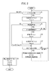
基本的には以上のように構成される車両制御装置10のTJA走行及びACC走行の抑制乃至許可の仕方を例として図2のフローチャートを参照して説明する。
[motion]
Basically, a method of suppressing or permitting TJA traveling and ACC traveling of the
ステップS1にて、乗員の操作によりパワースイッチ23がOFF位置からON位置に遷移したか否か、あるいはON位置にあるか否かが判定される。
In step S1, it is determined whether or not the
パワースイッチ23がON位置からOFF位置に遷移した(ステップS1:NO)場合には、図示しないバッテリの電力の車両100への供給が停止されるので、ステップS2の停止処理によりTJA許可フラグFtja、ヨーレートセンサ52の学習フラグFys、及びACC許可フラグFaccを全てリセットする(Ftja=0、Fys=0、Facc=0)。
When the
その一方、パワースイッチ23がOFF位置からON位置に遷移した(ステップS1:YES)場合、又はON位置にある(ステップS1:YES)場合には、図示しないバッテリの電力が車両100へ供給され、車両制御装置10の全ての構成部材に故障がなく問題なく動作していることを確認した上で、ステップS3にて、TJA許可フラグFtjaをセットする(Ftja=1)。
On the other hand, when the
次いで、ステップS4にて、車両速度Vに基づき車両100が、パワースイッチ23がON状態での停車中(V=0)か否か(V≠0)が判定される。
Next, in step S4, it is determined whether or not the
車両100が、パワースイッチ23がON状態での停車中である(ステップS4:YES)場合、補正処理部62は、ステップS5にてヨーレートセンサ52のゼロ点学習を行い、ゼロ点のずれ(オフセット)を補正する。
When the
ゼロ点学習は、パワースイッチ23のON後に、車両100が停車したままの安定状態が保持される一定の時間が必要であるので、ステップS5のゼロ点学習中(ステップS5:NO)には、ステップS4の車両100が停車中であるか否かの判断を継続する。
Since the zero point learning requires a certain period of time after the
ゼロ点学習が完了した(ステップS5:YES)場合、ステップS6にて学習フラグFysをセットする(Fys=1)。 When the zero point learning is completed (step S5: YES), the learning flag Fys is set in step S6 (Fys = 1).
さらに、ステップS7にて、ACC許可フラグFaccをセットし(Facc=1)処理をステップS8に移行する。 Further, in step S7, the ACC permission flag Facc is set (Facc = 1), and the process proceeds to step S8.
なお、ステップS6及びステップS7の処理は、順序は問わず、学習フラグFys及びACC許可フラグFaccは、同時にセットされる。 In the processes of steps S6 and S7, the learning flag Fys and the ACC permission flag Facc are set at the same time regardless of the order.
その一方、ステップS5のゼロ点学習完了前に車両100が走行を開始した(ステップS4:NO)場合には、学習フラグFys及びACC許可フラグFaccは、リセット状態が保持され(Fys=0、Facc=0)、処理をステップS8に移行する。
On the other hand, when the
ステップS8にて、ACC・TJAスイッチ21がON状態にされているか否かを判断し、ON状態にされている(ステップS8:YES)場合、TJA許可フラグFtja及びACC許可フラグFacc(学習フラグFys)がセットされているときは渋滞追従機能付きACC制御を実行し(ステップS7→ステップS8:YES→ステップS9)、TJA許可フラグFtjaのみがセットされているときは渋滞追従機能制御を実行し(ステップS3→ステップS4:NO→ステップS8:YES→ステップS9)、処理をステップS1に戻す。
In step S8, it is determined whether or not the ACC /
なお、TJA許可フラグFtja及びACC許可フラグFacc(学習フラグFys)がセットされているときに、ACC・TJAスイッチ21が能動状態(ON状態)にされている場合(ステップS5:YES→ステップS6→ステップS7→ステップS8:YES)であって、自車100の速度(自車速)が所定速度、例えば30[km/h]未満である場合には、ステップS9にて、自動的に渋滞追従機能制御を実行し、30[km/h]以上である場合には、ステップS9にて自動的に渋滞追従機能付きACC制御を実行するようにしてもよい。
When the ACC /
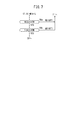
図3は、メモリ64に記憶されている渋滞追従機能付きACC制御(第1制御状態ともいう。)と、渋滞追従機能制御(第2制御状態ともいう。)の車間距離及び自車速の設定マップ(設定表)90を示している。
FIG. 3 is a setting map of the inter-vehicle distance and the own vehicle speed of the ACC control with the traffic jam tracking function (also referred to as the first control state) and the traffic jam tracking function control (also referred to as the second control state) stored in the
渋滞追従機能付きACC制御では、車間距離設定が最小〜最大の範囲で設定可能とされ、自車速設定が、例えば30[km/h]以上の高車速設定が可能である。渋滞追従機能制御では、車間距離設定が最小のみの設定が可能とされ、自車速設定が、例えば30[km/h]〜40[km/h]の範囲での低車速設定が可能である。 In the ACC control with the traffic jam tracking function, the inter-vehicle distance setting can be set in the minimum to maximum range, and the own vehicle speed setting can be set to a high vehicle speed of, for example, 30 [km / h] or more. In the traffic jam tracking function control, it is possible to set only the minimum inter-vehicle distance setting, and it is possible to set the own vehicle speed in the range of, for example, 30 [km / h] to 40 [km / h].
なお、前回のステップS4、S5の処理にて、ヨーレートセンサ52の学習ができなかった(ステップS4:NO)場合であって、学習フラグFysとACC許可フラグFaccがセットされていなかった場合でも、例えば、赤信号での停車中あるいは渋滞追従機能制御による前走車追従走行中に前走車の停止に合わせた自車100の自動停止中に、ステップS5にて、ゼロ点学習が完了したときには、ステップS6、S7にて、学習フラグFysとACC許可フラグFaccがセットされる(Fys=1、Facc=1)。
Even if the
この場合には、ステップS9にて、渋滞追従機能制御から渋滞追従機能付きACC制御に移行する。 In this case, in step S9, the control of the traffic jam tracking function is changed to the ACC control with the traffic jam tracking function.
[実施形態のまとめ]
以上説明したように、実施形態に係る車両制御装置10は、自車両100の挙動(ヨーレート)を検出するヨーレートセンサ52(車両センサ)と、自車両100の周囲の外界情報を取得する外界センサ14と、自車両100の挙動に基づき、自車両100が前記外界情報に適合するように第1制御状態(渋滞追従機能付きACC制御)又は第2制御状態(渋滞追従機能制御)で走行制御する走行制御装置28と、を有している。
[Summary of embodiments]
As described above, the
ここで、走行制御装置28は、ヨーレートセンサ52(車両センサ)の検出精度が所定未満であると判断した場合、例えばヨーレートセンサ52が学習されていないと判断した(ステップS5:NO→ステップS4:NO)場合(Fys=0)には、第1制御状態(渋滞追従機能付きACC制御)での走行制御を抑制し(Facc=0)、第2制御状態(渋滞追従機能制御)での走行制御を許可する(Ftja=1)ようにしたので、第2制御状態(渋滞追従機能制御)に対応する一定の範囲での走行制御を行うことができる。従って、機能の過剰な制限が未然に防止されて該車両制御装置10を搭載する車両100の商品性が向上する。
Here, when the
この場合、第2制御状態(渋滞追従機能制御)での走行制御は、図3の設定マップ90を参照して説明したように、第1制御状態(渋滞追従機能付きACC制御)での走行制御に比較し、前走車との車間距離設定が短い設定になっているか、自車速設定が低い設定になっている。
In this case, the running control in the second control state (traffic jam following function control) is the running control in the first control state (ACC control with the traffic jam following function) as described with reference to the
このように、学習フラグFys及びACC許可フラグFaccがセットされていない場合でも、パワースイッチ23がON状態になっていれば、TJA許可フラグFtjaをセットするようにしているので、車間距離設定が短い、又は自車速設定が低い設定において実行可能な第2制御状態(渋滞追従機能制御)での走行制御を行うことができる。これにより、機能の過剰な制限(例えば、TJA許可フラグFtjaのセットをゼロ点学習の完了に依存させ、ゼロ点学習の未完了時に、TJA許可フラグFtjaまでリセットしてしまうこと)を防止することができる。
In this way, even if the learning flag Fys and the ACC permission flag Facc are not set, if the
なお、走行制御装置28は、走行時の停車中時等にヨーレートセンサ52のゼロ点学習が完了されたことを検出した場合(ステップS4:YES→ステップS5:YES)に、第1制御状態(渋滞追従機能付きACC制御)での走行制御の抑制を解除するようにしている。
When the
ヨーレートセンサ52の学習が完了次第、第1制御状態(渋滞追従機能付きACC制御)での走行制御が可能となるので、第2制御状態(渋滞追従機能制御)での走行制御から第1制御状態(渋滞追従機能付きACC制御)での走行制御に円滑に切り替えることができる。
As soon as the learning of the
この実施形態に係る車両制御装置10では、ACC・TJAスイッチ21は、第1制御状態(渋滞追従機能付きACC制御)及び第2制御状態(渋滞追従機能制御)を能動状態又は抑制状態に切り替える兼用スイッチとされている。
In the
走行制御装置28は、兼用スイッチとしてのACC・TJAスイッチ21が能動状態(ON状態)側に切り替えられた(ステップS8:YES)場合に、ヨーレートセンサ52が学習されていない(学習フラグFys=0)と判断したときに(ステップS5:NO→ステップS4:NO)、第1制御状態(渋滞追従機能付きACC制御)での走行制御を抑制し、第2制御状態(渋滞追従機能制御)での走行制御を許可(ステップS9)するようにしたので、運転者等の乗員に対するHMI性が向上する。
In the
また、兼用スイッチとしてのACC・TJAスイッチ21が能動状態(ON状態)側に切り替えられている(ステップS8:YES)場合に、ヨーレートセンサ52が学習されていると判断したとき{ステップS5:YES→ステップS6(Fys=1)→ステップS7(Facc=1)}、上述したように、自車100の速度(自車速)が所定速度、例えば30[km/h]未満である場合には、ステップS9にて、自動的に渋滞追従機能制御を実行し、30[km/h]以上である場合には、ステップS9にて自動的に渋滞追従機能付きACC制御を実行するようにしてもよい。
Further, when it is determined that the
[変形例1]
変形例1では、車両100の挙動であるヨーレートを検出するのに、ヨーレートセンサ52で検出されるヨーレート及びヨーレートジャイロセンサ48で検出されるヨーレートの、例えば平均ヨーレートをヨーレートとして使用することで、ヨーレートの精度を向上させる。
[Modification 1]
In the first modification, the yaw rate detected by the
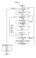
図4のフローチャートを参照して変形例1を説明する。なお、図4に示した処理と図2に示した一連の処理は、ステップS2´、S5´、S6´の処理を除き互いに一致する。ここでは、図4で示す処理のうち、図2で示す処理と相違する処理について説明する。
パワースイッチ23がON位置からOFF位置に遷移した(ステップS1:NO)場合には、ステップS2´の停止処理によりTJA許可フラグFtja、ヨーレートセンサ52の学習フラグFys、ACC許可フラグFacc、及びヨーレートジャイロセンサ48の学習フラグFgsを全てリセットする(Ftja=0、Fys=0、Facc=0、Fgs=0)。
When the
ステップS5´にて、ヨーレートセンサ52及びヨーレートジャイロセンサ48のゼロ点学習を行い、両方のゼロ点学習が完了したときに、ステップS6´にて、ヨーレートセンサ52の学習フラグFysとヨーレートジャイロセンサ48の学習フラグFgsをセットする(Fys=1、Fgs=1)。
In step S5', zero point learning of the
なお、実際上は、ステップS4:YES、ステップS5´にて、ヨーレートセンサ52のゼロ点学習が完了したときに、学習フラグFysがセットされ、ヨーレートジャイロセンサ48のゼロ点学習が完了したときに、学習フラグFgsがセットされるように別々にセットされる。
In practice, when the zero point learning of the
このように、変形例1では、車両センサは、少なくとも1つの同一の挙動であるヨーレートを検出可能なヨーレートセンサ52(第1車両センサ)及びヨーレートジャイロセンサ48(第2車両センサ)により構成されている。 As described above, in the first modification, the vehicle sensor is composed of the yaw rate sensor 52 (first vehicle sensor) and the yaw rate gyro sensor 48 (second vehicle sensor) capable of detecting at least one yaw rate having the same behavior. There is.
ステップS9では、変形例1に係る図5Aの機能制御マップ(機能表)102に示すように、走行制御装置28は、車両センサが冗長設計となっていて、ACC・TJAスイッチ21がON状態であって、ヨーレートセンサ52又はヨーレートジャイロセンサ48のいずれかが学習されていない{ステップS5´:NO→ステップS4:NOで、いずれかの学習フラグFys、Fgsがリセット(0値と)されている}場合には、第1制御状態(渋滞追従機能付きACC制御)での走行制御を抑制し(図5A中、ACC機能制御が「NG」でTJA機能制御が「OK」)、両方が学習されている(Fys=1、Fgs=1)場合に、第1制御状態(渋滞追従機能付きACC制御)での走行制御を許可する(ステップS9、図5A中、ACC機能制御が「OK」)ので、車両走行時における適応性に優れる。
In step S9, as shown in the function control map (function table) 102 of FIG. 5A according to the
なお、ACC・TJAスイッチ21がOFF状態である場合には、学習フラグFys、Fgsのセット、リセットにかかわらず、第1制御状態(渋滞追従機能付きACC制御)及び第2制御装置(渋滞追従機能制御)での走行制御を抑制する。
When the ACC /
[変形例1の応用例]
上述した変形例1の制御では、図4、図5Aを参照して説明したように、ACC・TJAスイッチ21がON状態(ステップS8:YES)であって、学習フラグFys、Fgsのいずれかがリセット状態(Fys=0、Fgs=1又はFys=1、Fgs=0)である場合、第1制御状態(渋滞追従機能付きACC制御)の機能を抑制している(ACC機能制御:NG)。
[Application example of modification 1]
In the control of the above-described
しかし、これに限らず、車両100の重心位置近傍に装着されているヨーレートセンサ52と、ナビゲーション装置16に装着されているヨーレートジャイロセンサ48は、いずれも車両100のヨーレートを検出可能であることに留意する。
However, not limited to this, the
この場合、学習フラグFys、Fgsのいずれかがセット状態(Fys=0、Fgs=1又はFys=1、Fgs=0)にある場合、換言すれば、ヨーレートセンサ52又はヨーレートジャイロセンサ48のいずれかの学習が完了した場合、学習完了済みのセンサのゼロ点のずれ(オフセット)であるセンサ値を基に残りのセンサのゼロ点のずれ(オフセット)を推定(推定学習)するようにしてもよい。
In this case, if any of the learning flags Fys and Fgs is in the set state (Fys = 0, Fgs = 1 or Fys = 1, Fgs = 0), in other words, either the
ヨーレートセンサ52とヨーレートジャイロセンサ48のゼロ点のずれ(オフセット)は、相関関係があり、該相関関係を、例えば、予めマップ化しておき、学習完了済みのセンサのゼロ点のずれ(オフセット)であるセンサ値で該マップを参照することで、残りのセンサのゼロ点のズレ(オフセット)であるセンサ値を推定(推定学習)することができる。
The deviation (offset) of the zero points of the
このように、学習完了した一方の車両センサのゼロ点のずれ(オフセット)を基に、他方の車両センサのゼロ点のズレ(オフセット)を推定(推定学習)することで学習フラグFys、Fgsが共にセットしているとみなし、ステップS9では、渋滞追従機能付きACC制御を実行するように構成を変更してもよい。 In this way, the learning flags Fys and Fgs are set by estimating (estimate learning) the deviation (offset) of the zero point of the other vehicle sensor based on the deviation (offset) of the zero point of one vehicle sensor that has completed learning. It is considered that they are set together, and in step S9, the configuration may be changed so as to execute the ACC control with the traffic jam tracking function.
この[変形例1の応用例]では、車両センサは、少なくとも1つの同一の挙動を検出可能な第1車両センサとしてのヨーレートセンサ52及び第2車両センサとしてのヨーレートジャイロセンサ48により構成されている。
In this [application example of modification 1], the vehicle sensor is composed of a
そして、走行制御装置28は、ヨーレートセンサ52(前記第1車両センサ)又はヨーレートジャイロセンサ48(前記第2車両センサ)のいずれかの検出精度が所定以上であることを検出した場合、例えば学習フラグFys、Fgsのいずれかが学習完了した場合には、学習が完了した車両センサの学習値を反映したセンサ値に基づいて、学習が完了していないセンサを、車両100の停車中、走行中に係わらず校正(推定学習)することが可能になるので、速やかに両方のセンサの検出精度を高めることができ、機能の過剰な制限を抑制することができる。
When the
[変形例2]
図6に示す変形例2の車両制御装置10Aを搭載した車両100Aでは、図1例の車両制御装置10を搭載した車両100に比較して、1つのACC・TJAスイッチ21を、ACCスイッチ21aとTJAスイッチ21bと別々に設け、運転者等のユーザのHMI性を向上させる。
[Modification 2]
In the
この変形例2は、図2のフローチャート又は図4のフローチャートにおいて、ステップS8の処理が変更される。
In this
図7は、変形例2の処理を説明するフローチャートである。ここでは、その他の処理は、図2のフローチャートの処理と一致する。
FIG. 7 is a flowchart illustrating the process of the
ステップS8aにて、ACCスイッチ21aがON状態であるかOFF状態であるかが判定され、さらにステップS8bにて、TJAスイッチ21bがON状態であるかOFF状態であるかが判定される。
In step S8a, it is determined whether the
ステップS9(図4参照)では、変形例2に係る図5Bの機能制御マップ(機能表)104に示すように、ヨーレートセンサ52が学習されていない(Fys=0)と判断した場合には、ACCスイッチ21aをON状態に切り替えても該切り替え操作を無効としてACC機能制御を抑制し、この場合に、TJAスイッチ21bがON状態に切り替えられていることを条件(切り替え操作を有効)として、TJA機能制御のみを許可するようにしている。ACCスイッチ21aとTJAスイッチ21bとを別々に設けているために、ユーザに対するHMI性が向上する。
In step S9 (see FIG. 4), when it is determined that the
なお、この発明に係る車両制御装置は、上述の実施形態に限らず、本発明の要旨を逸脱することなく、種々の構成を採り得ることはもちろんである。 It should be noted that the vehicle control device according to the present invention is not limited to the above-described embodiment, and of course, various configurations can be adopted without departing from the gist of the present invention.
例えば、ヨーレートセンサ52に限らず、加速度センサ、舵角センサ等の自車両100の挙動を検出する車両センサに適用してもよい。
For example, it may be applied not only to the
また、ACC・TJAスイッチ21、ACCスイッチ21a、及びTJAスイッチ21bをOFF状態からON状態へ操作したにもかかわらず、ACC機能制御及び/又はTJA機能制御が抑制される場合には、その旨及びその理由を報知装置36を通じて報知することが好ましい。このように報知することにより、車両制御装置10、10AがよりユーザフレンドリーなHMI性を有することになる。
If the ACC function control and / or the TJA function control is suppressed even though the ACC /
10、10A…車両制御装置 12…外界認識システム
16…ナビゲーション装置 48…ヨーレートジャイロセンサ
52…ヨーレートセンサ 68…フラグ情報
100、100A…車両
10, 10A ...
Claims (6)
前記自車両の周囲の外界情報を取得する外界センサと、
前記自車両の挙動に基づき、前記自車両が前記外界情報に適合するように第1制御状態又は第2制御状態で走行制御する走行制御装置と、を有し、
前記走行制御装置は、
前記車両センサの検出精度が所定未満である場合に、前記第1制御状態での走行制御を抑制し、前記第2制御状態での走行制御を許可する車両制御装置において、
前記第1制御状態を能動状態又は抑制状態に切り替える第1スイッチと、前記第2制御状態を能動状態又は抑制状態に切り替える第2スイッチと、をさらに備え、
前記走行制御装置は、
前記車両センサが学習されていないと判断した場合には、前記第1スイッチの切り替え操作を無効とし、前記第2スイッチの切り替え操作を有効とし、前記第2制御状態での走行制御のみを許可する
ことを特徴とする車両制御装置。 A vehicle sensor that detects the behavior of your vehicle, and
An outside world sensor that acquires outside world information around the own vehicle,
It has a traveling control device that controls traveling in a first control state or a second control state so that the own vehicle conforms to the outside world information based on the behavior of the own vehicle.
The travel control device is
In a vehicle control device that suppresses driving control in the first control state and permits driving control in the second control state when the detection accuracy of the vehicle sensor is less than a predetermined value.
A first switch for switching the first control state to the active state or the suppression state, and a second switch for switching the second control state to the active state or the suppression state are further provided.
The travel control device is
When it is determined that the vehicle sensor has not been learned, the switching operation of the first switch is invalidated, the switching operation of the second switch is enabled, and only the traveling control in the second control state is permitted. A vehicle control device characterized by that.
前記自車両の周囲の外界情報を取得する外界センサと、
前記自車両の挙動に基づき、前記自車両が前記外界情報に適合するように第1制御状態又は第2制御状態で走行制御する走行制御装置と、を有し、
前記走行制御装置は、
前記車両センサの検出精度が所定未満である場合に、前記第1制御状態での走行制御を抑制し、前記第2制御状態での走行制御を許可する車両制御装置において、
前記第1及び第2制御状態を能動状態又は抑制状態に切り替える兼用スイッチをさらに備え、
前記走行制御装置は、
前記兼用スイッチが能動状態側に切り替えられた場合に、前記車両センサの検出精度が所定未満であると判断したときに、前記第1制御状態での走行制御を抑制し、前記第2制御状態での走行制御を許可する
ことを特徴とする車両制御装置。 A vehicle sensor that detects the behavior of your vehicle, and
An outside world sensor that acquires outside world information around the own vehicle,
It has a traveling control device that controls traveling in a first control state or a second control state so that the own vehicle conforms to the outside world information based on the behavior of the own vehicle.
The travel control device is
In a vehicle control device that suppresses driving control in the first control state and permits driving control in the second control state when the detection accuracy of the vehicle sensor is less than a predetermined value.
Further, a dual-purpose switch for switching the first and second control states between the active state and the suppressed state is provided.
The travel control device is
When it is determined that the detection accuracy of the vehicle sensor is less than a predetermined value when the combined switch is switched to the active state side, the traveling control in the first control state is suppressed, and in the second control state. A vehicle control device characterized by permitting driving control of a vehicle.
前記第2制御状態での走行制御は、前記第1制御状態での走行制御に比較し、前走車との車間距離設定を短い設定に制限しているか、自車速設定を低い設定に制限している
ことを特徴とする車両制御装置。 In the vehicle control device according to claim 1 or 2.
Compared to the driving control in the first control state, the traveling control in the second control state limits the vehicle-to-vehicle distance setting with the preceding vehicle to a shorter setting or the own vehicle speed setting to a lower setting. A vehicle control device characterized by being
前記走行制御装置は、
前記車両センサの検出精度が所定以上であることを検出した場合に、前記第1制御状態での前記走行制御の抑制を解除する
ことを特徴とする車両制御装置。 The vehicle control device according to any one of claims 1 to 3.
The travel control device is
A vehicle control device, characterized in that, when it is detected that the detection accuracy of the vehicle sensor is equal to or higher than a predetermined value, the suppression of the traveling control in the first control state is released.
前記車両センサは、少なくとも1つの同一の挙動を検出可能な第1車両センサ及び第2車両センサにより構成されており、
前記走行制御装置は、
前記第1車両センサ又は前記第2車両センサのいずれかの検出精度が所定未満の場合には、前記第1制御状態での走行制御を抑制し、両方の検出精度が所定以上の場合に、前記第1制御状態での走行制御を許可する
ことを特徴とする車両制御装置。 In the vehicle control device according to any one of claims 1 to 3.
The vehicle sensor is composed of a first vehicle sensor and a second vehicle sensor capable of detecting at least one identical behavior.
The travel control device is
When the detection accuracy of either the first vehicle sensor or the second vehicle sensor is less than the predetermined value, the running control in the first control state is suppressed, and when both detection accuracys are equal to or higher than the predetermined value, the driving control is suppressed. A vehicle control device characterized in that driving control is permitted in the first control state.
前記車両センサは、少なくとも1つの同一の挙動を検出可能な第1車両センサ及び第2車両センサにより構成されており、
前記走行制御装置は、
前記第1車両センサ又は前記第2車両センサのいずれかの検出精度が所定以上であることを検出した場合には、検出精度が不明の残りの車両センサを、検出精度が所定以上であることを検出した車両センサの検出値を利用して使用に供する
ことを特徴とする車両制御装置。
In the vehicle control device according to any one of claims 1 to 3.
The vehicle sensor is composed of a first vehicle sensor and a second vehicle sensor capable of detecting at least one identical behavior.
The travel control device is
When it is detected that the detection accuracy of either the first vehicle sensor or the second vehicle sensor is equal to or higher than a predetermined value, the remaining vehicle sensors whose detection accuracy is unknown are determined to have a detection accuracy of a predetermined value or higher. A vehicle control device characterized in that it is used by using the detected value of the detected vehicle sensor.
Priority Applications (3)
| Application Number | Priority Date | Filing Date | Title |
|---|---|---|---|
| JP2018026272A JP6970626B2 (en) | 2018-02-16 | 2018-02-16 | Vehicle control device |
| US16/276,088 US11014558B2 (en) | 2018-02-16 | 2019-02-14 | Vehicle control apparatus |
| CN201910117665.3A CN110171421B (en) | 2018-02-16 | 2019-02-15 | Vehicle control device |
Applications Claiming Priority (1)
| Application Number | Priority Date | Filing Date | Title |
|---|---|---|---|
| JP2018026272A JP6970626B2 (en) | 2018-02-16 | 2018-02-16 | Vehicle control device |
Publications (3)
| Publication Number | Publication Date |
|---|---|
| JP2019142288A JP2019142288A (en) | 2019-08-29 |
| JP2019142288A5 JP2019142288A5 (en) | 2021-04-22 |
| JP6970626B2 true JP6970626B2 (en) | 2021-11-24 |
Family
ID=67617559
Family Applications (1)
| Application Number | Title | Priority Date | Filing Date |
|---|---|---|---|
| JP2018026272A Active JP6970626B2 (en) | 2018-02-16 | 2018-02-16 | Vehicle control device |
Country Status (3)
| Country | Link |
|---|---|
| US (1) | US11014558B2 (en) |
| JP (1) | JP6970626B2 (en) |
| CN (1) | CN110171421B (en) |
Families Citing this family (8)
| Publication number | Priority date | Publication date | Assignee | Title |
|---|---|---|---|---|
| EP3770712B1 (en) * | 2018-03-19 | 2022-09-21 | Honda Motor Co., Ltd. | Autonomous traveling work machine |
| JP7158356B2 (en) * | 2019-09-25 | 2022-10-21 | 本田技研工業株式会社 | travel control device |
| KR102274802B1 (en) * | 2019-11-22 | 2021-07-08 | 한양대학교 산학협력단 | Method for controling vehicle in abnornal situation of acc |
| JP6982108B2 (en) * | 2020-01-30 | 2021-12-17 | 本田技研工業株式会社 | Vehicle control devices, vehicle control methods and programs |
| JP6936350B2 (en) * | 2020-02-05 | 2021-09-15 | 本田技研工業株式会社 | Vehicle control device and vehicle control method |
| CN111806456A (en) * | 2020-07-20 | 2020-10-23 | 上汽通用五菱汽车股份有限公司 | Traffic jam auxiliary control method, system and storage medium |
| FR3116252B1 (en) * | 2020-11-19 | 2023-03-24 | Renault Sas | System and method of control adapted to perception |
| JP2023132591A (en) * | 2022-03-11 | 2023-09-22 | 日野自動車株式会社 | Yaw rate calibration device |
Family Cites Families (8)
| Publication number | Priority date | Publication date | Assignee | Title |
|---|---|---|---|---|
| JPS6426913A (en) * | 1987-07-23 | 1989-01-30 | Nissan Motor | Controller for self-traveling vehicle |
| JP2012066777A (en) * | 2010-09-27 | 2012-04-05 | Mazda Motor Corp | Yaw rate deviation detection apparatus |
| JP6205947B2 (en) * | 2013-07-26 | 2017-10-04 | 日産自動車株式会社 | Automatic operation control device |
| JP5939226B2 (en) * | 2013-10-16 | 2016-06-22 | トヨタ自動車株式会社 | Driving assistance device |
| US9308914B1 (en) * | 2015-01-23 | 2016-04-12 | Denso International America, Inc. | Advanced driver assistance system for vehicle |
| WO2016139747A1 (en) * | 2015-03-03 | 2016-09-09 | パイオニア株式会社 | Vehicle control device, control method, program, and storage medium |
| JP6211043B2 (en) * | 2015-11-05 | 2017-10-11 | 三菱電機株式会社 | Vehicle collision prevention device |
| JP6515814B2 (en) * | 2016-01-06 | 2019-05-22 | 株式会社デンソー | Driving support device |
-
2018
- 2018-02-16 JP JP2018026272A patent/JP6970626B2/en active Active
-
2019
- 2019-02-14 US US16/276,088 patent/US11014558B2/en active Active
- 2019-02-15 CN CN201910117665.3A patent/CN110171421B/en active Active
Also Published As
| Publication number | Publication date |
|---|---|
| CN110171421A (en) | 2019-08-27 |
| CN110171421B (en) | 2022-08-23 |
| US20190256093A1 (en) | 2019-08-22 |
| US11014558B2 (en) | 2021-05-25 |
| JP2019142288A (en) | 2019-08-29 |
Similar Documents
| Publication | Publication Date | Title |
|---|---|---|
| JP6970626B2 (en) | Vehicle control device | |
| JP6677822B2 (en) | Vehicle control device | |
| JP6630267B2 (en) | Vehicle control device | |
| US10202123B2 (en) | Vehicle control system | |
| JP6469635B2 (en) | Vehicle control device | |
| CN108216213B (en) | Vehicle control device | |
| CN109426244B (en) | Automatic driving device | |
| JP6473735B2 (en) | Vehicle control device | |
| CN110678372B (en) | Vehicle control device | |
| JP2019144975A (en) | Vehicle control device | |
| JP7115184B2 (en) | Autonomous driving system | |
| WO2018073886A1 (en) | Vehicle control device | |
| JP2019142337A (en) | Vehicle control device | |
| JP6637193B2 (en) | Vehicle control device | |
| JP6637194B2 (en) | Vehicle control device | |
| JP6674560B2 (en) | External recognition system | |
| CN111204344B (en) | Vehicle travel control device | |
| JP6731071B2 (en) | Vehicle control device and method | |
| JP2021149178A (en) | Vehicle controller, vehicle, vehicle controller operation method, and program | |
| JP7252993B2 (en) | CONTROL DEVICE, MOVING OBJECT, CONTROL METHOD AND PROGRAM | |
| JP2021018743A (en) | Image display device |
Legal Events
| Date | Code | Title | Description |
|---|---|---|---|
| A621 | Written request for application examination |
Free format text: JAPANESE INTERMEDIATE CODE: A621 Effective date: 20201130 |
|
| A521 | Request for written amendment filed |
Free format text: JAPANESE INTERMEDIATE CODE: A523 Effective date: 20210311 |
|
| A131 | Notification of reasons for refusal |
Free format text: JAPANESE INTERMEDIATE CODE: A131 Effective date: 20210824 |
|
| A521 | Request for written amendment filed |
Free format text: JAPANESE INTERMEDIATE CODE: A523 Effective date: 20211012 |
|
| TRDD | Decision of grant or rejection written | ||
| A01 | Written decision to grant a patent or to grant a registration (utility model) |
Free format text: JAPANESE INTERMEDIATE CODE: A01 Effective date: 20211026 |
|
| A61 | First payment of annual fees (during grant procedure) |
Free format text: JAPANESE INTERMEDIATE CODE: A61 Effective date: 20211029 |
|
| R150 | Certificate of patent or registration of utility model |
Ref document number: 6970626 Country of ref document: JP Free format text: JAPANESE INTERMEDIATE CODE: R150 |