WO2018105235A1 - Antenna device - Google Patents
Antenna device Download PDFInfo
- Publication number
- WO2018105235A1 WO2018105235A1 PCT/JP2017/037195 JP2017037195W WO2018105235A1 WO 2018105235 A1 WO2018105235 A1 WO 2018105235A1 JP 2017037195 W JP2017037195 W JP 2017037195W WO 2018105235 A1 WO2018105235 A1 WO 2018105235A1
- Authority
- WO
- WIPO (PCT)
- Prior art keywords
- antenna
- antenna device
- vehicle roof
- case
- loading elements
- Prior art date
Links
Images


Classifications
-
- H—ELECTRICITY
- H01—ELECTRIC ELEMENTS
- H01Q—ANTENNAS, i.e. RADIO AERIALS
- H01Q1/00—Details of, or arrangements associated with, antennas
- H01Q1/52—Means for reducing coupling between antennas; Means for reducing coupling between an antenna and another structure
-
- H—ELECTRICITY
- H01—ELECTRIC ELEMENTS
- H01Q—ANTENNAS, i.e. RADIO AERIALS
- H01Q1/00—Details of, or arrangements associated with, antennas
- H01Q1/27—Adaptation for use in or on movable bodies
- H01Q1/32—Adaptation for use in or on road or rail vehicles
- H01Q1/325—Adaptation for use in or on road or rail vehicles characterised by the location of the antenna on the vehicle
- H01Q1/3275—Adaptation for use in or on road or rail vehicles characterised by the location of the antenna on the vehicle mounted on a horizontal surface of the vehicle, e.g. on roof, hood, trunk
-
- H—ELECTRICITY
- H01—ELECTRIC ELEMENTS
- H01Q—ANTENNAS, i.e. RADIO AERIALS
- H01Q1/00—Details of, or arrangements associated with, antennas
- H01Q1/12—Supports; Mounting means
-
- H—ELECTRICITY
- H01—ELECTRIC ELEMENTS
- H01Q—ANTENNAS, i.e. RADIO AERIALS
- H01Q1/00—Details of, or arrangements associated with, antennas
- H01Q1/12—Supports; Mounting means
- H01Q1/22—Supports; Mounting means by structural association with other equipment or articles
-
- H—ELECTRICITY
- H01—ELECTRIC ELEMENTS
- H01Q—ANTENNAS, i.e. RADIO AERIALS
- H01Q1/00—Details of, or arrangements associated with, antennas
- H01Q1/27—Adaptation for use in or on movable bodies
- H01Q1/32—Adaptation for use in or on road or rail vehicles
-
- H—ELECTRICITY
- H01—ELECTRIC ELEMENTS
- H01Q—ANTENNAS, i.e. RADIO AERIALS
- H01Q1/00—Details of, or arrangements associated with, antennas
- H01Q1/36—Structural form of radiating elements, e.g. cone, spiral, umbrella; Particular materials used therewith
-
- H—ELECTRICITY
- H01—ELECTRIC ELEMENTS
- H01Q—ANTENNAS, i.e. RADIO AERIALS
- H01Q1/00—Details of, or arrangements associated with, antennas
- H01Q1/42—Housings not intimately mechanically associated with radiating elements, e.g. radome
-
- H—ELECTRICITY
- H01—ELECTRIC ELEMENTS
- H01Q—ANTENNAS, i.e. RADIO AERIALS
- H01Q1/00—Details of, or arrangements associated with, antennas
- H01Q1/48—Earthing means; Earth screens; Counterpoises
-
- H—ELECTRICITY
- H01—ELECTRIC ELEMENTS
- H01Q—ANTENNAS, i.e. RADIO AERIALS
- H01Q21/00—Antenna arrays or systems
- H01Q21/28—Combinations of substantially independent non-interacting antenna units or systems
-
- H—ELECTRICITY
- H01—ELECTRIC ELEMENTS
- H01Q—ANTENNAS, i.e. RADIO AERIALS
- H01Q5/00—Arrangements for simultaneous operation of antennas on two or more different wavebands, e.g. dual-band or multi-band arrangements
- H01Q5/30—Arrangements for providing operation on different wavebands
- H01Q5/307—Individual or coupled radiating elements, each element being fed in an unspecified way
- H01Q5/342—Individual or coupled radiating elements, each element being fed in an unspecified way for different propagation modes
- H01Q5/357—Individual or coupled radiating elements, each element being fed in an unspecified way for different propagation modes using a single feed point
- H01Q5/364—Creating multiple current paths
- H01Q5/371—Branching current paths
-
- H—ELECTRICITY
- H01—ELECTRIC ELEMENTS
- H01Q—ANTENNAS, i.e. RADIO AERIALS
- H01Q9/00—Electrically-short antennas having dimensions not more than twice the operating wavelength and consisting of conductive active radiating elements
- H01Q9/04—Resonant antennas
- H01Q9/30—Resonant antennas with feed to end of elongated active element, e.g. unipole
- H01Q9/32—Vertical arrangement of element
- H01Q9/36—Vertical arrangement of element with top loading
Definitions
- the present invention relates to a low-profile antenna device that is attached to a vehicle roof and can receive radio waves for a plurality of media.
- Patent Documents 1 to 3 As conventional antenna devices attached to a vehicle roof or the like, those disclosed in Patent Documents 1 to 3 are known.
- an antenna portion is housed in an antenna case that protrudes at a distance of 70 mm or less from the vehicle roof.
- the antenna section is provided with an antenna element that receives radio waves in the FM wave band and a metal plate provided in an umbrella shape near the top of the antenna element in order to increase the gain of the AM wave band.
- An object of the present invention is to provide an antenna device that can reduce stray capacitance even if it is small and low-profile, and can also be mounted with other media antennas without hindrance.
- An antenna device provided by the present invention is an antenna device attached to a vehicle roof, and includes a radio wave transmissive case portion in which a storage space is formed, and an antenna portion stored in the storage space. ing.
- Each of the antenna portions is opposed to each other at a predetermined interval and a predetermined angle with a plane orthogonal to the vehicle roof as a center, and a connection portion is provided at a portion lower than the upper edge, and a pair of conductors are connected to each other via each connection portion. It is characterized by including a capacity loading element and a helical element that is electrically connected to each of the connecting portions to enable reception of FM broadcasts.
- (A)-(c) is an external view of the antenna apparatus which concerns on 1st Embodiment. Arrangement explanatory drawing of the parts which constitute the antenna device concerning a 1st embodiment.
- (A)-(c) is structure explanatory drawing of a holder.
- (A)-(d) is structure explanatory drawing of a capacity
- (A)-(c) is structure explanatory drawing of a helical element.
- A)-(d) is structure explanatory drawing of AM * FM antenna.
- the external appearance perspective view which shows the state of the antenna part accommodated in storage space.
- the perspective view which shows the structural example of the antenna apparatus containing the antenna part of storage space.
- (A)-(e) is a figure which showed the example of a change of the electrical property of a SDARS antenna.
- (A)-(c) is an illustration figure of the connection part of capacitive loading elements.
- (A)-(c) is structure explanatory drawing of the antenna device which concerns on 2nd Embodiment.
- (A) is structure explanatory drawing of the antenna device which concerns on 3rd Embodiment.
- (A)-(c) is structure explanatory drawing of the AM / FM antenna in 4th Embodiment.
- (A) is an external appearance perspective view of the antenna device which concerns on 5th Embodiment
- (b) is the partial notch figure in (a).
- FIG. 22 is an explanatory diagram of an arrangement of components constituting the SDARS antenna of FIG.
- FIG. 22 is a cross-sectional view taken along the line AA ′ of FIG. The figure which shows the positional relationship of the parasitic element for SDARS, and an antenna main body.
- the simulation figure which shows the gain change by the direction of a SDARS antenna.
- (A), (b) is structure explanatory drawing of a capacity
- This antenna apparatus includes a plurality of types of antennas in order to receive or transmit / receive radio waves for a plurality of media.
- the vehicle roof side is downward
- the upward direction is upward from the vehicle roof
- the longitudinal direction of the present invention is the front-rear direction (front is front, the rear is rear)
- the direction perpendicular to the longitudinal direction is left and right. It is called direction.
- the vertical direction may be expressed as front and back, or expressions similar to them may be used.
- the antenna device 1 includes a case portion made of synthetic resin having radio wave permeability in which a storage space is formed, and an antenna portion stored in the storage space.
- the case portion includes an antenna case 10 having an opening surface portion on the lower surface side and an inner case (not shown).
- the antenna device 1 also includes a base portion 20 that closes the opening surface portion of the antenna case 10, and a capture portion 30 that attaches the antenna device 1 to the vehicle roof and takes a ground.
- the antenna case 10 is formed into a streamlined shape that becomes thinner and lower toward the front (going to the tip), and has a curved surface curved inward (toward the central axis in the longitudinal direction).
- the lower surface portion of the antenna case 10 is formed in a shape that matches the shape of a vehicle roof mounting surface (the bottom surface of the vehicle roof side portion to which the antenna device 1 is mounted, the same applies hereinafter).
- the length of the antenna case 10 in the longitudinal direction is about 230 mm, the width is about 75 mm, and the height is about 70 mm.
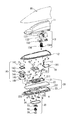
- FIG. 2 is an explanatory diagram of component arrangement of the antenna device 1.
- the antenna device 1 includes an inner case 11 whose outer wall has a shape corresponding to the shape of the inner wall of the antenna case 10.
- the inner case 11 is made of a radio wave transmitting synthetic resin, and its lower surface side is open.
- a groove portion and a plurality of bosses for screwing and fixing to the base portion 20 are formed on the outer flange of the lower surface portion.
- the storage space is formed inside the inner case 11 and is used to protect the antenna.
- the O-ring 22 is sandwiched and fixed between the inner wall of the inner case 11 and the outer wall of the inner rib of the insulating wall of the insulating base 23. It is the structure which can ensure the dust-proof inside the apparatus 1, and waterproofness.
- the resin engagement piece provided on the inner rear side of the antenna case 10 is aligned with the engagement piece fitting portion of the insulation base 23, and the front of the antenna case 10 and the insulation base 23 is used as a fulcrum.
- the antenna case 10 is fixed to the insulating base 23 by engaging the locking claws provided on the left and right sides.
- fixed pieces are provided on the left and right portions of the antenna case 10, and the fixed pieces are inserted into the fixed piece holes provided in the insulating base 23 and assembled. Yes.
- the fixing piece By providing the fixing piece, it is possible to prevent the antenna case 10 from being deformed by the external force received by the antenna case 10, and to reduce the external force transmitted to the locking claw because the external force is distributed to the fixing piece. The engagement between the locking claws can be prevented from being disengaged.
- a pad 12 made of soft insulation is attached between the outer edge of the lower surface of the inner case 11 and the opening end of the antenna case 10.
- the pad 12 is sandwiched and fixed when the antenna case 10 is fixed to the base portion 20. Since the pad 12 closes the gap between the vehicle roof and the antenna case 10 and the inner case 11, it is possible to improve the aesthetics and to improve the dust resistance and waterproofness. In particular, it prevents water from being directly blown onto the sealing material 34 due to water discharge from the car wash machine, thereby improving the waterproofness of the sealing material 34.
- an AM / FM antenna 13 receives an AM broadcast radio wave of 522 kHz to 1710 kHz and an FM broadcast radio wave of 76 MHz to 108 MHz. Further, LW broadcast radio waves of 153 kHz to 279 kHz can also be received.
- the SDARS antenna 14 that receives circularly polarized waves receives radio waves in the 2.3 GHz band, which is a satellite digital audio radio service.
- the LTE (Long Term Evolution) antenna 15 transmits and receives radio waves from the 700 MHz band to the 2.7 GHz band.
- GNSS Global Navigation Satellite System
- GPS Global Navigation Satellite System
- GLONASS Galileo
- QZSS Quasi-Zenith Satellite
- the GNSS antenna 16 that receives circularly polarized waves receives radio waves around 1.5 GHz band of GNSS.
- the telephone antenna 17 transmits and receives radio waves from the 700 MHz band to the 2.7 GHz band.
- the telephone antenna 17 is actually a kind of LTE antenna.
- the AM / FM antenna 13 is screwed to the inner wall boss of the inner case 11 and is elastically held by an M-shaped connecting piece 191 that is an elastic conductive member formed on the substrate 19.
- the SDARS antenna 14 is screwed and held on the insulating base 23.
- the LTE antenna 15 and the GNSS antenna 16 are fixed to the conductive base 21 via the substrate 18.
- the telephone antenna 17 is fixed to the conductive base 21 via the substrate 19.
- the signals received and amplified by the antennas 13 to 17 are sent to the vehicle-side electronic circuit through the signal cables C1, C2, and C3.
- the AM / FM antenna 13 includes a pair of capacitive loading elements 131 and 132, a holder 133 made of synthetic resin having radio wave permeability, and a helical element 134.
- the capacitive loading elements 131 and 132 are elements each having an electrical delay portion, for example, a composite shape formed in a meander shape, in the substantially central portion, and do not resonate by themselves in the AM / FM band. However, it functions as a capacity loading plate that adds (loads) ground capacitance to the helical element 134, improves the function as a voltage receiving element in the AM band, and the AM / FM antenna 13 resonates in the FM band.
- the helical element 134 is inserted between the capacitive loading elements 131 and 132 and the AM / FM amplifier circuit, and operates as a helical antenna that resonates in the FM wave band in cooperation with the capacitive loading elements 131 and 132.
- the helical element 134 is formed by winding a linear conductor around a hollow bobbin, and terminal terminals (lower terminal terminals in the example shown in FIG. 2) are respectively connected to the ends of the linear conductors at the upper and lower ends. 1341) is formed, and the lower terminal terminal 1341 is elastically held by the M-shaped connecting piece 191 described above.
- the structure of the AM / FM antenna 13 will be described in detail later.
- the SDARS antenna 14 includes a parasitic element 141, a parasitic element holder 142, a planar antenna 143, an SDARS amplifier substrate 144, a shield cover 145, and a ground plate 146.
- the planar antenna 143 is an SDARS main antenna, and the thin metal plate parasitic element 141 is provided above the planar antenna 143 with a predetermined interval in order to improve the antenna gain of the planar antenna 143.
- a shield cover 145 formed of a thin metal plate in a box shape is a conductive member that electrically shields the SDARS amplifier board 144.
- the ground plate 146 is a conductive member that serves as a ground (grounded part, the same applies hereinafter) of the planar antenna 143.
- the shield cover 145 and the ground plate 146 may be integrated.
- Such an SDARS antenna 14 is disposed in a concave portion of the insulating base 23 existing in front of the conductive base 21.
- the ground plate 146 is separated from the vehicle roof by a predetermined distance. Further, it is electrically separated from the ground of other antennas other than the SDARS antenna. The reason will be described later.
- the LTE antenna 15 is erected on the substrate 18.
- the GNSS antenna 16 is a planar antenna and is attached to the surface of the substrate 18.
- a GNSS antenna 16 is electrically connected to the input portion of the GNSS amplifier circuit.
- the LTE antenna 15 is electrically connected to the input portion of the LTE antenna matching circuit. Electrical connection is performed by soldering or the like.
- the telephone antenna 17 is erected on the surface of the substrate 19.
- the base portion 20 has a metal conductive base 21 that has the same potential as that of the vehicle roof after being mounted on the vehicle roof, an O-ring 22 that is a soft insulator, and an outer periphery that matches the shape of the lower surface portion of the antenna case 10. And an insulating base 23 made of resin.
- the insulating base 23 is made of a resin having strength for holding the conductive base 21, the antenna case 10, the inner case 11, and the SDARS antenna 14.
- the conductive base 21 is a member having a predetermined strength constituted by die casting, and has the same potential as the vehicle roof when mounted, and functions as a ground (ground).
- the recess 211 accommodates an electronic component such as an AM / FM amplifier circuit mounted on the back surface of the substrate 19.
- the recess 212 accommodates an electronic component such as a GNSS amplifier circuit mounted on the back surface of the substrate 18.
- the wall portion 213 shields these storage spaces. That is, the concave portions 211 and 212 and the wall portion 213 position the substrates 18 and 19 and form independent shield regions. That is, the conductive base 21 also serves as a shield member for various electronic components.
- Screw holes for fixing the substrates 18, 19 and the like with screws are also formed around the recesses 211, 212. However, in order to prevent leakage of radio waves in a desired frequency band, it is desirable that the screw hole interval be 1 ⁇ 2 or less of the wavelength of the radio waves. Note that portions such as signal output patterns of the substrates 18 and 19 may be opened. On the other hand, on the back side of the conductive base 21, a boss for fixing the capture portion 30 with screws is projected downward.
- the outer periphery of the insulating base 23 has a shape corresponding to the shape of the opening surface portion of the antenna case 10, and the inner case 11 is engaged with a guide groove for fitting the O-ring 22 slightly inside the outer periphery. And an engagement mechanism for the purpose.
- a flat component placement surface 231 is formed inside the guide groove and the engagement mechanism.
- a hole 232 for mechanically connecting the conductive base 21 and the capture unit 30 is formed at a substantially central portion of the component placement surface 231.
- a recess 233 is formed from the front of the insulating base 23. The SDARS antenna 14 is accommodated in the recess 233.
- the capture unit 30 includes a bolt 31, a vehicle fixing claw member 32, a pre-lock holder 33, a sealing material 34, and a metal spring 35.
- the pre-lock holder 33 temporarily fixes the antenna device 1 to the vehicle roof.
- the pre-lock holder 33 is provided with a locking claw.
- the antenna mounting boss is inserted into the mounting hole on the vehicle roof side and fitted, the locking claw is fitted around the mounting hole on the vehicle roof side.
- the antenna device 1 can be temporarily fixed before the bolt 31 is tightened, and the workability of attaching the antenna to the vehicle roof is improved.
- the claw of the vehicle fixing claw member 32 is opened.
- the front end of the fixed claw member 32 cuts the painted surface of the vehicle roof, so that the vehicle roof and the conductive base 21 are electrically connected to have substantially the same potential and are mechanically fixed. Further, the sealing material 34 fixed to the back surface of the insulating base 23 with an adhesive or the like by tightening the bolt 31 is compressed because it has elasticity. As a result, dust entering the vehicle through the vehicle roof can be prevented or waterproofed. Moreover, the rust prevention and waterproofness of the conductive base 21 and the metal spring 35 can be ensured.
- the curvature of the vehicle roof on which the antenna device 1 is mounted may vary depending on the vehicle type.
- the metal spring 35 is a slidable member having a convex portion at the abutment with the vehicle roof, and is deformed so as to follow the shape (curvature) of the vehicle roof. The effect will be described later.
- the AM / FM antenna 13 includes a three-dimensional holder 133 having a trapezoidal cross section.
- 3A is a top view of the holder 133
- FIG. 3B is a front view
- FIG. 3C is a side view.
- the holder 133 is made of a radio wave-transmitting synthetic resin that is long in the front-rear direction and short in the left-right direction
- the upper bottom surface 1331 is substantially flat.
- a groove portion 1332 having a flat bottom surface with a predetermined width is formed in the upper bottom surface 1331 slightly forward from the long central portion.
- a screw hole 1333 is formed in a predetermined portion of the groove portion 1332.
- the screw hole 1333 is for fixing the capacity loading elements 131 and 132 and the helical element 134 to the inner wall boss of the inner case 11 with screws.
- a plurality of ribs 1334 having various widths exist on both sides of the holder 133.
- a locking claw 1335 is formed on any of the ribs 1334. The ribs 1334 and the locking claws 1335 not only restrict the angle and position of the capacity loading elements 131 and 132 but also improve the strength of the holder.
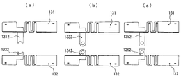
- FIG. 4 is an explanatory view showing the shape and arrangement example of the capacity loading elements 131 and 132, in which (a) is a top view, (b) is a front view, and (c) is a side view.
- FIG. 6D is a size explanatory diagram of these capacity loading elements 131 and 132.
- each of the capacity loading elements 131 and 132 is an element composed of a composite element in which a front surface portion that is forward and a rear surface portion that is rearward is connected by a belt-like meander portion.
- the “meander portion” refers to a surface formed by thin conductor elements formed so as to have a meandering shape at least once.
- Both are substantially symmetrical elements, one of which is opposed to the other at a predetermined interval and a predetermined angle with respect to a plane orthogonal to the vehicle roof.
- the interval and angle are determined according to the shape of the inner space of the inner case 11. Further, the rear surface portion has a high height structure.
- the capacity loading elements 131 and 132 are formed with connecting portions 1312 and 1322 at portions lower than the uppermost portion (hereinafter referred to as “the zenith portion”) when attached, and these connecting portions 1312 and 1322 are formed. Through each other.
- Each of the connecting portions 1312 and 1322 can be realized by forming a slit in a part of each of the capacity loading elements 131 and 132 and then bending the slit.
- the lengths of the connecting portions 1312 and 1322 are different in order to clarify the mounting direction of the one capacitive loading element 131 and the other capacitive loading element 132 that are substantially symmetrical, but they must always be so. It is not a thing.
- Fixing holes 1311 and 1321 are formed in the front surface portion and the rear surface portion of these capacity loading elements 131 and 132. These fixing holes 1311 and 1321 are used for fitting into the locking claws 1335 of the holder 133. As a result, since the capacity loading elements 131 and 132 can be locked to the holder 133 without using an adhesive or the like, not only the assembly process is simplified, but also electrical characteristics due to the use of the adhesive or the like are reduced. Variations can be suppressed. Further, instead of fixing with the locking claw, after temporarily fixing with the locking claw, it is possible to heat and heat and fix it by welding with the holder.
- the height a1 of the front surface portion shown in FIG. 4D is about 26 mm
- the length a2 in the horizontal direction is about 23 mm
- the length a3 in the horizontal direction of the meander portion is about 14 mm
- the rear The lateral length a4 of the direction portion is 23 mm.
- the meander part also has a path length in the height direction.
- the SDARS wavelength ⁇ 1 is about 120 mm, the height a1, the lengths a2 and a4 are about 1 ⁇ 4 or less of the SDARS wavelength ⁇ 1, and the meander path length is about 1 ⁇ 2. Therefore, the impedance when the meander portion (starting end) is viewed from the front surface portion becomes high at the SDARS frequency and is electrically separated. That is, the capacitive loading elements 131 and 132 function as impedance converters in a frequency band used for SDARS, for example. The impedance is the same when the meander part (rear end) is viewed from the rear face part. Therefore, for the SDARS antenna 14, the capacity loading elements 131 and 132 are conductors having a size that does not affect their own operation (including directivity).
- the impedance from the rear end portion to the meander portion direction and from the front end portion to the meander portion direction becomes high in the SDARS frequency band, and thus is not affected by the SDARS radio wave. That is, they do not interfere with each other.
- the wavelength ⁇ 2 of the GNSS is about 190 mm and the electrical length of the capacitive loading elements 131 and 132 is set to a length that does not resonate so as not to be 1 ⁇ 2 of the wavelength ⁇ 2 of the GNSS, the capacitive loading elements 131 and 132 are There is no interference with the GNSS antenna 16.
- the lateral length is about 60 mm and the wavelength ⁇ 1 Therefore, at least for the SDARS antenna 14, effects such as a decrease in gain and distortion of directivity are likely to occur. Further, the height is about twice the height a1, and is also about 1 ⁇ 2 of the wavelength ⁇ 1, and the SDARS antenna 14 is likely to be affected by a decrease in gain and distortion of directivity.
- the plate thickness of the capacitive loading elements 131 and 132 with respect to the wavelengths ⁇ 1 and ⁇ 2 is set to 1 to 2 mm or less (thickness sufficiently small with respect to the wavelengths ⁇ 1 and ⁇ 2), and the height If a2 is a wavelength of about 1 ⁇ 4 or less than the wavelength ⁇ 1 of the radio wave received by the planar antenna 143, and the path length of the meander portion is about 1 ⁇ 2 plus or minus 8 with respect to the wavelength ⁇ 1, AM / There was no interference between the FM antenna 13 and the SDARS antenna 14.
- the capacity loading elements 131 and 132 have a length that does not resonate with the radio wave received by the GNSS antenna 16, no interference was observed between the AM / FM antenna 13 and the GNSS antenna 16.
- the length of the front surface portion and the rear surface portion electrically separated by the meander portion is preferably about 1 ⁇ 4 or less of the wavelength ⁇ 1.
- the capacity loading elements 131 and 132 having a structure in which the zenith portion is open also exhibit excellent effects in relation to the helical element 134. That is, since the zenith portions of the capacity loading elements 131 and 132 are opened, the projected area of the helical element 134 and the zenith portion is reduced as compared with the case where capacity loading is performed on one sheet. Therefore, in the capacity loading elements 131 and 132, the eddy current that works to cancel the high-frequency current generated in the helical element 134 is reduced. Thereby, the efficiency deterioration of the AM / FM antenna 13 is reduced.
- the degree of freedom of the arrangement position of the helical element 134 with respect to the zenith portion is improved. For example, it is not always necessary to arrange the helical element 134 at the center of the top of the capacity loading elements 131 and 132.
- the structure according to the present embodiment in which the top portions of the capacity loading elements 131 and 132 are opened eliminates the need to bend or draw the capacity loading elements 131 and 132, thereby simplifying the machining process and contributing to a reduction in manufacturing costs. To do.
- Such a structure also has an effect of reducing the stray capacitance generated between adjacent conductors, in this example, between the telephone antenna 17 and the case of using a capacitive loading plate on one surface.
- the stray capacitance is a reactive capacitance component that is not intended by the designer, and is caused by a physical structure. As described above, the gain decreases as the stray capacitance increases.
- the telephone antenna 17 is disposed substantially at the center between the side edges of the front surface portions of the capacitive loading elements 131 and 132 facing each other. This also makes it possible to reduce the stray capacitance, so that the facing distance between the telephone antenna 17 and the capacitive loading elements 131 and 132 can be shortened as shown in FIGS.
- one or more holes or slits may be formed in the capacity loading elements 131 and 132. By doing so, the stray capacitance with the ground mainly on the lower surface side of the capacity loading elements 131 and 132 can be reduced, so that sufficient performance can be obtained even if the lower surface side is constituted by a conductive base.
- FIG. 5A is a top view of the helical element 134
- FIG. 5B is a front view
- FIG. 5C is a rear view.
- the helical element 134 is formed by winding a conducting wire around a cylindrical bobbin made of radio wave transmitting synthetic resin.
- a groove having a determined diameter and pitch is formed so that a desired shape of the helical antenna can be configured, and by winding a linear conductor around the bobbin as many times as necessary, It can operate as a helical antenna.
- a lower terminal terminal 1341 electrically connected to one end of the conducting wire is formed at the lower part of the bobbin.
- the lower terminal terminal 1341 is elastically held by the M-shaped connection piece 191 described above and is electrically connected to the input terminal of the AM / FM amplification circuit mounted on the back surface of the substrate 19.
- the upper terminal terminal 1342 is electrically connected to the other end of the conducting wire.
- a metal screw is inserted upward from the bobbin, and the foot of this metal screw is inserted into the circular hole formed by the screw hole 1333 of the holder 133 and the coupling parts 1312, 1322 of the capacity loading elements 131, 132, and these are inserted.
- the metal screw may be a screw with a spring washer to enhance mechanical retention.
- the upper terminal 1342 can be attached to the bobbin by inverting 180 degrees, and the number of turns of the helical element 134 can be adjusted every half turn while sharing parts. The frequency can be adjusted, and the degree of design freedom can be improved.
- FIG. 6 shows a state in which the capacity loading elements 131 and 132 are fixed to the holder 133 and the helical element 134 is attached to the holder 133.
- 6A is a top view
- FIG. 6B is a front view
- FIG. 6C is a side view
- FIG. 6D is a bottom view.
- the degree of freedom of the arrangement position of the helical element 134 is improved as compared with the case of a single-surface capacitive loading plate with the zenith portion closed.
- the lower terminal terminal 1341 is positioned approximately in the middle of the capacity loading elements 131 and 132, and the helical element 134 itself is slightly eccentric to the capacity loading element 132 side.
- the capacitive loading element adjacent to the helical element 134 becomes the capacitive loading element 132. Therefore, electrical interference can be generated only with the capacitive loading element 132, and interference can be reduced and performance degradation can be suppressed compared to when electrical interference occurs with both capacitive loading elements 131 and 132. Become.
- the helical element 134 may be slightly eccentric to the capacity loading element 131 side.
- FIG. 7 is an external perspective view showing a state in which only the antenna case 10, the inner case 11, and the O-ring 22 are removed from the antenna device 1 assembled according to the arrangement shown in FIG.
- FIG. 8 is an explanatory view showing a state in which the storage space is seen through with the antenna case 10, the inner case 11, and the O-ring 22 assembled.
- the edges of the capacitive loading elements 131 and 132 are separated from each other, and a plane parallel to the vehicle roof is opened. Therefore, ground capacitance is added to the helical element 134 by the capacitive loading elements 131 and 132, but stray capacitance is reduced. Therefore, the gain of AM broadcast and FM broadcast is improved.
- the edges of the opposing capacitive loading elements 131 and 132 are discontinuous, interference with radio waves received by other media antennas can be suppressed.
- the antenna device 1 is a low profile and narrow storage space having a length in the longitudinal direction of about 230 mm, a width of about 75 mm, and a height of about 70 mm
- the antenna 17 and the AM / FM antenna 13 can be arranged side by side in this order without interfering with each other.
- the AM / FM antenna 13 and the telephone antenna 17 are arranged close to each other. Therefore, the AM / FM antenna 13 that performs reception at a frequency lower than that of the telephone antenna 17 is easily affected by the telephone antenna 17. Therefore, in the present embodiment, among the matching circuits mounted on the back surface of the substrate 19, a capacitor of preferably about 20 pF is preferably connected in series to the feeding point of the telephone antenna 17, and then the impedance matching is performed on the received signals of each frequency. I did it.
- 20 pF has an impedance of about 80 k ⁇ at 1 MHz in the AM band, and about 80 ⁇ at 100 MHz in the FM band.
- the frequency band received by the telephone antenna 17 for example, at 800 MHz or more, it becomes 10 ⁇ or less, and the impedance becomes remarkably low. Further, since impedance matching with the telephone antenna 17 is performed by the matching circuit, the loss becomes smaller in the reception band of the telephone antenna 17. Considering the reception bandwidth of the telephone antenna 17, it is preferably about 2 pF to 20 pF. As a result, the gain of both the telephone antenna 17 and the AM / FM antenna 13 can be secured.
- a BEF Band Elimination Filter
- a parallel resonant circuit using an inductor and a capacitor can be configured to increase the impedance in the vicinity of the AM band or the FM band, thereby obtaining the same effect.
- a filter having a high impedance frequency of the telephone antenna 17 is connected in series between the M-shaped connecting piece 191 that feeds the AM / FM antenna 13 and the AM / FM amplifier, so that no mutual interference occurs. I did it.
- the filter is configured such that a chip capacitor is not disposed in the signal path and the ground, and the AM band received signal is not divided and attenuated by the capacitor.
- a filter that reflects or attenuates a desired frequency band of the telephone antenna 17 by using parallel resonance of an inductor and a capacitor or an open stub is configured.
- the SDARS amplifier board 144 is mounted on the back side of the SDARS planar antenna 143, and the planar antenna 143 and the SDARS amplifier board 144 are placed in the parasitic element holder that houses the parasitic element 141. 142 and a metal shield cover 145. At least two or more ribs for positioning with the SDARS planar antenna 143 are provided on the lower surface of the parasitic element holder 142. Further, the thickness of the parasitic element holder 142 is set so that the distance between the parasitic element 141 and the SDARS planar antenna 143 is constant.
- the conductive parasitic element 141 is provided with at least one positioning slit, and positioning is performed by fitting the slit to the positioning rib of the parasitic element holder 142.
- This may be a structure in which the parasitic element 141 is provided with a protrusion and the parasitic element holder 142 has a concave shape.
- These holes are fixed by tightening the holes provided in the SDARS amplifier board 144 and the holes provided in the ground plate 146 with screws.
- the ground plate 146 is disposed in front of the insulating base 23 and is fitted so as to be positioned in a recess 233 provided inside the rib of the insulating base 23.
- the thickness of the insulating base 233 in the portion where the recess 233 is formed is thinner than the thickness of the portion where the recess 233 is not formed, but the recess 233 is formed on the inner side of the rib of the insulating base 23 and the shape of the ground plate 146. Therefore, the strength of the insulating base 23 is sufficiently maintained.
- the ground plate 146 is not connected to the conductive base 21 so as to be electrically separated from the conductive base 21. This is to prevent the influence of electrical characteristics on the LTE antenna 15 and / or the telephone antenna 17 and the influence of directivity on the SDARS antenna 14.
- the conductive base 21 functions as a ground for the LTE antenna 15, the GNSS antenna 16, the telephone antenna 17, and the AM / FM antenna 13, but depending on the distance between the vehicle roof and the conductive base 21 and the size of the conductive base 21, This also causes unnecessary resonance (resonance phenomenon). Unnecessary resonance is more likely to occur as the conductive base 21 becomes larger. When unnecessary resonance occurs, the gain of an antenna that receives radio waves in a band including the frequency decreases. Further, depending on the curvature of the vehicle roof on which the antenna device 1 is mounted, the capacitance component between the conductive base 21 and the vehicle roof may change, and the gain of each antenna 13 to 17 may decrease or change due to unnecessary resonance. .
- the unnecessary resonance is briefly explained.
- the inductance of the conductive base 21 and the portion of the capture unit 30 up to the vehicle fixing claw member 32 is L
- the capacitance of the space between the conductive base 21 and the vehicle roof is C
- the frequency f of the unnecessary resonance is 1 / [2 ⁇ (LC )].
- the area between the conductive base 21 and the vehicle roof is S
- the distance between the conductive base 21 and the vehicle roof is d
- the relative dielectric constant of the space is ⁇
- the capacitance C is ⁇ ⁇ S / d.
- the conductor loss is R
- the conductive base 21 is increased and the area S is increased, the capacitance C is increased and the frequency f of unnecessary resonance is decreased. As a result, the frequency f of the unwanted resonance becomes a frequency included in the band of the frequency used for transmission or reception (within the specification band), and the gain of the antenna that receives the radio wave in the band including the frequency may decrease. is there.
- the frequency f of unnecessary resonance increases, the Q value increases, and the gain of each antenna 13 to 17 decreases.
- the capacitance C increases, the unnecessary resonance frequency f decreases, and the Q value decreases.
- the capacitance C greatly varies depending on the curvature of the vehicle roof, and the frequency f of the unwanted resonance also varies greatly.
- the antenna device 5 is made to have a vehicle with various curvatures. It can be attached to the roof.
- the metal spring 35 has slidability, so that the protruding convex portion deforms following the curvature of the vehicle roof. For this reason, the variation amount of the capacitance C is reduced, and the variation amount of the frequency f of the unnecessary resonance is also reduced, so that it can be attached to the vehicle roof having various curvatures.
- the convex portion of the metal spring 35 is brought into contact with the vehicle roof.
- the capacitance C is increased, and the frequency f of the unnecessary resonance is shifted to a low range. . Therefore, the frequency of unnecessary resonance can be shifted out of the specification band.
- the SDARS antenna 14 is not arranged on the conductive base 21 but on the insulating base 23 in order to reduce the size of the conductive base 21 to such a size that unnecessary resonance does not enter.
- the ground of the SDARS planar antenna 143 is a ground plate 146 that is electrically separated from the conductive base 21. Since the reception band of the planar antenna 143 is a high frequency band such as the 2.3 GHz band, even if the ground plate 146 is separated, the antenna gain is ensured only by making it slightly larger than the planar antenna 143. A sufficient ground size can be obtained.
- the structure in which the ground plate 146 is separated from the conductive base 21 also has an effect of increasing the size of the ground plate 146 and the degree of freedom of the structure.
- the size and arrangement structure of the conductive base 21 are determined to some extent according to the required specifications of the antenna device 1. For example, the electrical length between the vehicle roof and the conductive base 21 is approximately 1 ⁇ 4 of the wavelength ⁇ 1 of SDARS. As a result, the electrical characteristics of the SDARS may deteriorate.
- the shape and size of the ground plate 146 can be arbitrarily set so that desired electrical characteristics of the SDARS antenna 14 can be obtained. Can be improved and the degree of freedom in design can be increased.
- FIG. 9 is a diagram showing an example of a change in electrical characteristics due to a change in the structure of the SDARS antenna 14.
- the SDARS antenna 14 is accommodated in the recess 233 of the insulating base 23.
- the concave portion 233 facilitates positioning of the ground plate 146 during assembly and improves workability.
- the depth (thickness) of the concave portion 233 is an element that determines the distance between the ground plate 146 and the vehicle roof.
- the ground plate 146 is slightly larger than the planar antenna 143.
- FIG. 9A when the distance between the vehicle roof and the ground plate 146 (the depth of the recess 233) is t, the vertical directivity of the planar antenna 143 is as shown in FIG.
- the distance t is 10 mm or less, preferably 2 mm to 10 mm.
- the distance t is 10 mm or less, preferably 2 mm to 10 mm.
- the shielding performance of the SDARS amplifier board 144 ensures the shielding effect by soldering or welding the periphery of the shield cover 145 to the SDARS amplifier board 144. Since the shield cover 145 is electrically connected to the ground plate 146, it has the same potential as the ground plate 146.
- a portion corresponding to the screw hole 1333 is a circular hole
- FIG. 10A when the connecting portions 1312 and 1322 are formed, the opposing end portions can be easily formed by cutting them into a semicircular shape.
- FIGS. 10B and 10C the opposing end portions of the connecting portions 1312 and 1322 may be formed in an R shape or a rectangular shape, and a circular hole may be formed in the vicinity of the tip portion thereof. .
- these circular holes play a role of positioning, an effect of facilitating the work for fixing to the holder 133 can be obtained.
- the meander shape is also in the vertical direction, the same effect can be obtained in the front-rear direction.
- the antenna device of the second embodiment is similar to the antenna device 1 of the first embodiment in the basic components such as an antenna case, an inner case, a base part, a plurality of antennas, a substrate, and a capture part, and the arrangement thereof.
- the shape of the capacitive loading element constituting the / FM antenna and the structure of the holder are different from the antenna device 1 of the first embodiment.
- FIG. 11A is a side view of the capacitive loading element included in the antenna device according to the second embodiment
- FIG. 11B is a top view
- FIG. 11C is an assembly description showing a part of the inner case cut out for convenience.
- the antenna device 2 of this embodiment includes a pair of capacitive loading elements 131b and 132b, and the same as the capacitive loading elements 131 and 132 of the first embodiment in that a part of them is a connecting portion 1312b and 1322b.
- the meander shape and the mounting structure to the holder 133b are different.
- the distal ends of the connecting portions 1312b and 1322b extend downward, and are electrically connected to each other by a metal screw via a conductive relay member.
- the upper and lower edges of the capacity loading elements 131b and 132b are separated from each other, and a plane parallel to the vehicle roof is opened. Therefore, although the ground capacitance is added to the helical element by the capacitive loading elements 131b and 132b, the stray capacitance is reduced. Since the connecting portions 1312b and 1322b extend downward, the generation of stray capacitance can be suppressed also in the connecting portions 1312b and 1322b. Therefore, the gain of AM broadcast and FM broadcast is improved. Moreover, since the edges of the opposing capacitive loading elements are discontinuous, interference with radio waves received by other media antennas can be suppressed.
- the antenna device of the third embodiment is also similar to the antenna device 1 of the first embodiment in the basic components such as the antenna case, the inner case, the base unit, the plurality of antennas, the substrate, and the capture unit, and the arrangement thereof.
- the shape of the capacitive loading element constituting the AM / FM antenna and the structure of the holder are different from the antenna device 1 of the first embodiment.
- FIG. 12A is an exploded view of a capacitive loading element included in the antenna device according to the second embodiment
- FIG. 12B is an external perspective view of the antenna device after assembly.
- the antenna device 3 includes a pair of capacitive loading elements 131c and 132c, and the same as the capacitive loading elements 131b and 132b according to the second embodiment, except that a part thereof is a connecting portion. The difference is that there are two meander shapes and two connecting portions.
- the upper and lower edges of the capacity loading elements 131c and 132c are separated from each other, and a surface parallel to the vehicle roof is opened. Therefore, although the ground capacitance is added to the helical element by the capacitive loading elements 131c and 132c, the stray capacitance is reduced. Therefore, the gain of AM broadcast and FM broadcast is improved. Moreover, since the edges of the opposing capacitive loading elements are discontinuous, interference with radio waves received by other media antennas can be suppressed.
- FIG. 14 is an explanatory view of the structure of the AM / FM antenna in the fourth embodiment.
- FIG. 14A is a top view
- FIG. 14B is a front view
- FIG. 14C is a side view.
- the antenna device 4 of the fourth embodiment is provided with a pair of capacitive loading elements 131d and 132d, a part of which is a connecting part, and a point fixed to the holder 133d through the fixing hole 1321d.
- the remaining portion of the portion that becomes the connecting portion and bends becomes the wide surface portion, the front becomes the first meander portion, and the rear becomes the second meander portion.
- the helical element 134 has the same components as the helical element 134 described in the first embodiment, but differs from the first embodiment in that the helical element 134 is disposed on the conductive base 21 outside the substrate 19. Therefore, the helical element 134 is eccentric toward the capacity loading element 131d.
- the upper and lower edges of the capacity loading elements 131d and 132d are separated from each other, and a plane parallel to the vehicle roof is opened. Therefore, ground capacitance is added to the helical element 134 by the capacitive loading elements 131d and 132d, but stray capacitance is reduced. Therefore, the gain of AM broadcast and FM broadcast is improved. Moreover, since the edges of the opposing capacitive loading elements are discontinuous, interference with radio waves received by other media antennas can be suppressed.
- the embodiments of the present invention are not limited to these embodiments.
- the pair of capacitive loading elements 131 (131b to 131d) and 132 (132b to 132d) (hereinafter abbreviated as “131 etc.”) and the helical element 134 are electrically connected through a connecting piece having a spring property. It may be.
- the capacitive loading elements 131 and the like are connected to each other by an LC element (inductor and capacitor) or a conductive pattern filter formed on the substrate. May be connected.
- the capacity loading element 131 or the like may be any one that functions as an electrical delay unit, such as at least one fold, zigzag shape, ninety-nine fold shape, and fractal shape.
- the upper edge and the lower edge of the capacity loading element 131 and the like are discontinuous, but the front edge and the rear edge may be discontinuous.
- the pair of capacity loading elements 131 and the like do not necessarily have a symmetrical shape.
- the arrangement of the SDARS planar antenna 143 and the GNSS antenna 16 may be reversed. Alternatively, the SDARS planar antenna 143 and the GNSS antenna 16 may be vertically stacked. Also, if the required performance requirements are not strict, the ground plate 146 is not set, and if the ground size of the SDARS amplifier board 144 or the shield cover 145 is sufficient, the shape is similarly recessed. As a result, improvement in electrical performance can be expected.
- the conductive base 21 is integrally formed by die casting or the like and the ground plate 146 is separately provided, the conductive base 21 is electrically connected to the conductive base 21 and the metal thin plate by screwing or welding. The thing comprised by the electric potential is also included.
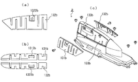
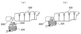
- FIG. 15A is an external perspective view of the antenna device according to the fifth embodiment
- FIG. 15B is a partially cutaway view of FIG. 15A viewed from the direction AA ′
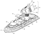
- FIG. 16 is an explanatory view of the arrangement of components constituting the antenna device according to the fifth embodiment.
- the antenna device 5 of the fifth embodiment is an antenna device that is attached to the vehicle roof, as in the previous embodiments, and is housed in a storage space, a radio wave transmissive case part in which a storage space is formed. And an antenna portion.
- the case portion includes an antenna case 50 having an opening surface portion on the lower surface side, and a base portion 60 that closes the opening surface portion of the antenna case 50 via a soft resin pad 52.
- the antenna case 50 is formed into a streamlined shape that becomes thinner and lower toward the front (going to the tip) and has a curved surface curved inward (toward the central axis in the longitudinal direction).
- the material and size of the antenna case 50 are substantially the same as those of the antenna case 10 of the first embodiment.
- the base unit 60 includes a conductive base 61 and an insulating base 63 for fixing the conductive base 61. Holes 611 and 612 through which cables C51, C53, C54, and C57 pass are formed in front and rear of the conductive base 61.
- the insulating base 63 is formed with mounting holes 631 for screwing and fixing the conductive base 61 from the vehicle roof side, and holes 632 and 633 for penetrating the cables C51, C53, C54, and C57. .
- Grooves for accommodating the metal spring 64 and the soft sealing material 65 are formed on the back surface of the insulating base 63. The metal spring 64 is deformed so as to follow the shape (curvature) of the vehicle roof.
- the metal spring 64 first suppresses the fluctuation amount of the capacitance C (the fluctuation amount of the frequency f of the unnecessary resonance), so that the antenna device 5 is attached to the vehicle roof having various curvatures. Second, the frequency f of unnecessary resonance can be shifted out of the specification band. Therefore, the applicable range of the vehicle roof that can provide a sufficient antenna gain can be expanded.
- the base portion 60 is fastened with a bolt from a vehicle roof side (not shown) and locked with a nut 66.
- the antenna portion is arranged such that the SDARS antenna 54, the telephone antenna 57, the AM / FM antenna 53, and the keyless entry antenna 51 are arranged in this order from the front.
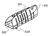
- the AM / FM antenna 53 is capable of receiving FM broadcasts by a pair of capacitive loading elements 531 and 532 electrically connected via a connecting portion 533 and one end thereof being electrically connected to the connecting portion 533.
- a helical element 535 The pair of capacitive loading elements 531 and 532 and the connecting portion 533 are fixed to an element holder 534 that is a hard insulating member, and are fixed to the inner wall of the antenna case 50 via screws 5331.
- the helical element 535 is fixed to the inner wall of the antenna case 50 with screws 5341 together with the element holder 534.
- a telephone antenna 57 is disposed in front of the capacity loading elements 531 and 532 at a predetermined interval so as to be electrically discontinuous with the capacity loading elements 531 and 532.
- the telephone antenna 17 of the first embodiment is an antenna for transmitting and receiving a signal having a frequency of 800 MHz band, but the upper part of the telephone antenna 57 of the fifth embodiment is folded along the inner wall of the antenna case 50. It is a planar conductor plate having a substantially ⁇ -shaped cross section, and has an element width larger than that of the telephone antenna 17. Therefore, it is possible to widen the bandwidth, and transmission / reception is possible even at a frequency of 700 MHz.
- the telephone antenna 57 is fixed to the inner wall of the antenna case 50 with screws 571.
- a substantially rectangular SDARS parasitic element 55 is disposed in front of the telephone antenna 57.
- the parasitic element 55 is fixed to the inner wall of the antenna case 50 with a screw 551.
- a keyless entry board 510, an AM / FM board 530, and a telephone board 570 each having an electronic circuit component mounted on an insulating member are fixed to the conductive base 61 with screws.
- the other end (feeding portion) of the helical element 535 is electrically connected to the circuit contact of the AM / FM substrate 530 while being elastically held.
- the circuit contact is electrically connected to an electronic circuit component such as an amplifier mounted on the AM / FM substrate 530.
- the electronic circuit component of the AM / FM board 530 is electrically connected to the vehicle-side electronic device through the cable C53.
- the power feeding portion of the telephone antenna 57 is electrically connected to the circuit contact of the telephone board 570 while being elastically held.
- the circuit contact is electrically connected to the electronic circuit component mounted on the telephone board 570, and the electronic circuit component is electrically connected to the vehicle-side electronic device through the cable C57.
- the keyless entry antenna 51 is erected on the keyless entry substrate 510.
- the keyless entry antenna 51 is an antenna in which a linear conductor 512 is wound around a cylindrical holder 511 made of an insulator, and receives a signal having a frequency in the 900 MHz band.
- the power feeding portion of the keyless entry antenna 51 is electrically connected to the electronic circuit components of the keyless entry substrate 510.
- the electronic circuit components of the keyless entry board 510 are electrically connected to the vehicle-side electronic device through the cable C51.
- the keyless entry antenna 51 is positioned so as to be electrically discontinuous with the pair of capacitive loading elements 531 and 532 behind the helical element 535 of the AM / FM antenna 53 in the longitudinal direction. Since the antenna device 5 is disposed at the rearmost position in the antenna portion, for example, on the rear side of the vehicle roof, not only vertical polarization but also horizontal polarization can be received well, and the horizontal gain is improved. be able to.
- the area of the conductive base 61 is larger than the areas of the capacity loading elements 531 and 532 when viewed from above. That is, the area of the conductive base 61 is larger than the projected area of the capacitive loading elements 531 and 532. Further, since the keyless entry antenna 51 is disposed below the capacity loading elements 531, 532, the keyless entry antenna 51 can be reliably grounded. Furthermore, since the gap between the capacitive loading elements 531 and 532 and the conductive base 61 is constant, the reception performance in the AM / FM wave band is not affected by the curvature of the vehicle roof.
- a ground plate 56 serving as a ground for the SDARS antenna 54 is fixed in front of the insulating base 63.
- the SDARS antenna 54 is electrically connected to the vehicle-side electronic device through the cable C54.
- Detailed shapes of the parasitic element 55, the SDARS antenna 54, and the ground plate 56 and their positional relationships will be described later.
- the telephone antenna 57 and the keyless entry antenna 51 are close in frequency. Therefore, interference can be reduced by interposing the AM / FM antenna 53 between the two and physically separating them.
- the frequency band of the AM / FM antenna 53 is far from the frequency band of the telephone antenna 57 and the keyless entry antenna 51. Therefore, even if the AM / FM antenna 53 and the telephone antenna 57 and the AM / FM antenna 53 and the keyless entry antenna 51 are physically close to each other, the AM / FM antenna 53 and the telephone antenna 57 can be operated almost without any trouble in each frequency band.
- the keyless entry antenna 51 is disposed behind and below the capacity loading elements 531 and 532, but is not limited thereto.
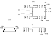
- FIG. 17 is an external perspective view of the capacity loading elements 531 and 532.
- 18 is an explanatory view of the shape of the capacity loading elements 531 and 532, (a) is a front view thereof, (b) is a top view thereof, (c) is a left side view thereof, and (d) is a top view thereof.
- the right side view, (e) is the bottom view.
- the pair of upper edges of the capacity loading elements 531 and 532 are separated from each other, and the others are integrally formed including the connecting portion 530 at the lower edge. That is, the connection part 530 also has an electrical delay part.
- a locking portion 5321 is formed in a part of the capacity loading elements 531 and 532, for example, in the lower part of the capacity loading element 532.
- the locking portion 5321 is formed to lock the capacity loading elements 531 and 532 to the element holder 533.
- the capacity loading elements 531 and 532 including the connecting portion 530 are formed in a meander shape.
- the capacity loading elements 53 and 532 have more meander-shaped portions than the capacity loading elements 131 and 132 of the first embodiment. Therefore, the electrical length of the capacity loading elements 53 and 532 is the capacity loading element of the first embodiment. It differs from the electrical length of 131,132.
- the electrical lengths of the capacitive loading elements 531 and 532 of the fifth embodiment are lengths that do not resonate in the frequency band used by the telephone antenna 57 (about 700 MHz to 800 MHz) and the keyless entry antenna 51, and the SDARS antenna 54 Longer than the wavelength of the frequency band used.
- the electrical length of the capacitive loading elements 531 and 532 is a length that does not resonate in the frequency band used by the SDARS antenna 54. Thereby, interference with the capacitive loading elements 531 and 532, the telephone antenna 57, and the keyless entry antenna 51 can be reduced. In addition, a drop in the horizontal directivity of the SDARS antenna 54 can be suppressed.
- FIG. 19 shows an example of the result of verifying the difference in characteristics between the telephone antenna 17 of the first embodiment and the telephone antenna 57 of the fifth embodiment.
- FIG. 19 is a simulation diagram showing the relationship between the frequency (700 MHz to 800 MHz) and the average gain (dBi).
- the broken line indicates the average gain G11 of the telephone antenna 17
- the solid line indicates the average gain G51 of the telephone antenna 57.
- the telephone antenna 57 has a higher average gain from 700 MHz to near 780 MHz compared to the telephone antenna 17. From this, it can be seen that according to the capacity loading elements 531 and 532 of the fifth embodiment, the interference given to the telephone antenna 57 is reduced more than the capacity loading elements 131 and 132 of the first embodiment.
- FIG. 20 is a simulation diagram showing the relationship between the frequency (915 MHz to 935 MHz) of the keyless entry antenna 51 and the average gain (dBi).
- the broken line indicates the average gain G12 of the keyless entry antenna 51 when the capacity loading elements 131 and 132 of the first embodiment are used instead of the capacity loading elements 531 and 532
- the solid line indicates the capacity loading elements 531 and 532.
- the average gain G52 of the keyless entry antenna 51 when used is shown.
- the average gain of the keyless entry antenna 51 is increased by using the capacity loading elements 531 and 532. That is, the keyless entry antenna 51 is less susceptible to interference by the capacity loading elements 531 and 532.
- the keyless entry antenna 51 Since the keyless entry antenna 51 has a narrow frequency band, there is no problem even if the height is lowered. Therefore, in the fifth embodiment, by arranging the keyless entry antenna 51 below the capacitive loading elements 531 and 532, the length of the antenna device 5 in the front-rear direction is increased despite the increase in the number of media (antennas). Is not so long as the antenna device 1 of the first embodiment.
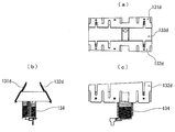
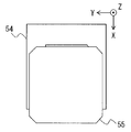
- FIG. 21 is an external perspective view of the SDARS antenna 54.
- FIG. 22 is an explanatory diagram of the arrangement of the components constituting the SDARS antenna 54.
- FIG. 23 is a cross-sectional view taken along the line AA ′ of FIG.
- the SDARS antenna 54 has a planar antenna 540 as a main antenna.
- the planar antenna 540 is fixed to the surface of the SDARS substrate 542 with a double-sided tape 541.
- Electronic circuit components such as an amplifier are mounted on the back surface of the SDARS substrate 542 and shielded by a shield cover 543.
- the shield cover 543 is fixed by screws to a ground plate 56 having a hole 561 formed in the center.
- the ground of the SDARS antenna 54 is separated from the vehicle roof by a predetermined distance and is electrically separated from the grounds of other antennas that receive radio waves other than the frequency band of the SDARS antenna 54. It is the same as the antenna device 1.
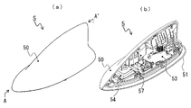
- FIG. 24 shows the positional relationship between the SDARS parasitic element 55 and the SDARS antenna 54 (antenna body 540) when the antenna case 50 is put on the base 60.
- the direction (Z) away from the paper surface is the zenith direction of the antenna device 5
- the downward direction (X) of the paper surface is the rear of the antenna device 5
- the left direction (Y) of the paper surface is the width direction of the antenna device 5.
- the parasitic element 55 is arranged to be shifted rearward (X direction) with respect to the SDARS antenna 54. Therefore, it is possible to suppress the influence of the antenna characteristics caused by the presence of the telephone antenna 57 and the like behind the SDARS antenna 54.
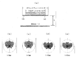
- FIG. 25 is a simulation diagram showing gain change depending on the direction of the SDARS antenna 54.
- the broken line indicates the gain when the parasitic element 55 is not shifted, and the solid line indicates the gain when it is shifted.
- the directivity Gx of the SDARS antenna 54 when the parasitic element is shifted backward (X direction) does not change greatly compared to the directivity Go when the parasitic element is not shifted, but the backward (X It can be seen that the gain in the (direction) increases in the shifted direction (X direction).
- the SDARS antenna 54 of the fifth embodiment has a parasitic element 55 shifted rearward (X direction) and has a hole 561 formed in the center of the ground plate 56. Is different. That is, in the SDARS antenna 54, the shield cover 543 and the ground plate 56 are not easily coupled, and the distance between the planar antenna 540 and the vehicle roof can be shorter than that of the planar antenna 143 of the first embodiment.
- FIG. 26 is an actual measurement diagram showing the relationship between the frequency and the gain in the 2.3 GHz band of the SDARS antenna 14 in the first embodiment and the SDARS antenna 54 in the fifth embodiment.
- the broken line represents the gain G13 of the SDARS antenna 14
- the solid line represents the gain G53 of the SDARS antenna 54.
- the average gain G13 of the SDARS antenna 14 at a frequency of 2320 MHz to 2345 MHz (for SDARS) was 28.7 dBi
- the average of the gain G53 of the SDARS antenna 54 was 31.0 dBi.
- the SDARS antenna 54 has a higher average gain at a frequency in the 2.3 GHz band than the SDARS antenna 14.
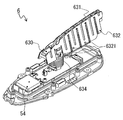
- FIG. 27 is an external perspective view of the antenna unit of the antenna device 6 according to the sixth embodiment.
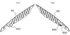
- FIGS. 28A and 28B are explanatory diagrams of the structure of the capacitive loading element in the antenna device 6.
- FIGS. 29A and 29B are explanatory diagrams of the attachment procedure of the element holder and the helical coil, in which FIG. 29A shows a state before assembly, and FIG.
- a buffer 6321 is provided in one or a plurality of portions in a gap between the pair of capacitive loading elements 631 and 632 and the inner wall of the antenna case to fill the gap.
- the buffer body 6321 may be formed by projecting the capacitive loading element 632 from the inside, for example, or may be provided on the inner wall of the antenna case.
- the connecting portions 6313 and 6323 extending from the capacity loading elements 631 and 632 are formed so as to overlap in the vertical direction when attached to the element holder 630, respectively.
- a protrusion 6325 is provided on the connecting portion 6313, 6323, which overlaps with the connecting portion 6323 in this example.
- FIG. 27 only the buffer body 6321 of one capacity loading element 632 is shown, but the other capacity loading element 631 that is not visible in FIG. Yes.
- These buffer bodies 6321 fill a gap with the inner wall of the antenna case when the assembly is completed. That is, it contacts the antenna case. Therefore, after the antenna device 6 is attached to the vehicle, it is possible to prevent the capacitive loading elements 631 and 632 from vibrating due to the vibration of the vehicle and generating abnormal noise.
- the reason why the connecting portions 6313 and 6323 overlap in the vertical direction is to ensure electrical connection between the pair of capacitive loading elements 631 and 632 and one helical element 634, but the protrusion 6325 has an error in the overlapping direction. It is provided to prevent That is, if the connecting portion 6323 is mistakenly stacked under the connecting portion 6313, the shape of the capacity loading elements 631, 632 is distorted, or the distance from one end of the helical element 634 to the end of each capacity loading element 631, 632 is different. End up.
- the protrusion 6325 is provided to prevent such a situation from occurring.
- the element holder 630 is formed with a guide having a predetermined thickness having a double-sided portion at a predetermined front portion, and a protrusion 6301 is provided on one surface of the guide (in the left direction in this example).
- a guide having a predetermined thickness having both side portions is also provided at the upper end portion of the cylindrical holder of the helical element 634, and a groove 6341 of a size to fit the projection 6301 is formed on one surface portion (left direction in this example) of the guide.
- the protrusion 6301 of the element holder 630 Prior to assembly, the protrusion 6301 of the element holder 630 is positioned above the groove 6341 of the helical element 634 as shown in FIG. Thereafter, the protrusion 6301 is fitted into the groove 6341 as shown in FIG.
- the helical element 134 By adopting such an attachment structure, it is possible to prevent the helical element 134 from being mistakenly assembled in the front-rear direction. Further, the helical element 634 is less likely to rotate with respect to the element holder 630, and the other end (feeding portion) of the helical element is securely held at the circuit contact of the AM / FM substrate 530.
Abstract
[Problem]
To provide an antenna device with which stray capacitance can be reduced and which can be mounted jointly with an antenna used for another medium without hindrance, while being compact and having a low height.
[Solution]
An AM/FM antenna 13 formed by securing a pair of capacity loaded elements 131 and 132 to a holder 133 by means of securing holes 1321, and securing a helical antenna 134 to the lower part of this holder 134. The capacity loaded elements 131 and 132 oppose one another with a prescribed interval and at a prescribed angle, and centered around a plane orthogonal to a vehicle roof. Furthermore, connecting parts are provided at a location lower than their respective upper edges, and the capacity loaded elements are electrically connected to each other via the connecting parts. The size of the edges of the capacity loaded elements 131 and 132 is set so as not to interfere with a SDARS antenna 14 or a GNSS antenna 19, for example.
Description
本発明は、車両ルーフに取り付けられ、複数のメディア用の電波を受信可能な低背型のアンテナ装置に関する。
The present invention relates to a low-profile antenna device that is attached to a vehicle roof and can receive radio waves for a plurality of media.
車両ルーフなどに取り付けられる従来のアンテナ装置として、特許文献1~3に開示されたものが知られている。これらのアンテナ装置は、車両ルーフから70mm以下で突出するアンテナケースにアンテナ部を収納している。アンテナ部は、FM波帯の電波を受信するアンテナ素子と、AM波帯の利得を高めるためにアンテナ素子の頂上付近に傘状に設けられた金属板が設けられている。
As conventional antenna devices attached to a vehicle roof or the like, those disclosed in Patent Documents 1 to 3 are known. In these antenna devices, an antenna portion is housed in an antenna case that protrudes at a distance of 70 mm or less from the vehicle roof. The antenna section is provided with an antenna element that receives radio waves in the FM wave band and a metal plate provided in an umbrella shape near the top of the antenna element in order to increase the gain of the AM wave band.
近年、AM放送及びFM放送のほかにも電話用アンテナやGPSアンテナなど、多数のメディア用のアンテナをアンテナケース内に混載する傾向がある。このため、特許文献1~3に開示されたアンテナ装置のように、小型低背化のためにアンテナ素子を1つの大きな金属板として設けた場合、他のメディア用アンテナが近接して配置されることとなり、近接するアンテナによって浮遊容量が大きくなる。浮遊容量は、設計者が意図しない無効容量成分であり、物理的な構造に起因する。この浮遊容量が大きくなるほど利得が低下する。また、近接しないアンテナにおいてもアンテナ相互の影響も受けやすくなっている。
In recent years, in addition to AM broadcasting and FM broadcasting, there is a tendency to incorporate a large number of media antennas such as telephone antennas and GPS antennas in an antenna case. Therefore, as in the antenna devices disclosed in Patent Documents 1 to 3, when the antenna element is provided as one large metal plate in order to reduce the size and height, other media antennas are arranged close to each other. As a result, the stray capacitance is increased by the adjacent antenna. The stray capacitance is a reactive capacitance component that is not intended by the designer, and is caused by a physical structure. The gain decreases as the stray capacitance increases. In addition, antennas that are not close to each other are easily affected by each other.
本発明の課題は、小型低背であっても浮遊容量を低減させることができ、他のメディア用のアンテナをも支障なく混載することができるアンテナ装置を提供することにある。
An object of the present invention is to provide an antenna device that can reduce stray capacitance even if it is small and low-profile, and can also be mounted with other media antennas without hindrance.
本発明が提供するアンテナ装置は、車両ルーフに取り付けられるアンテナ装置であって、その内部に収納空間が形成されている電波透過性のケース部と、前記収納空間に収納されるアンテナ部とを備えている。前記アンテナ部は、それぞれ前記車両ルーフと直交する面を中心として所定間隔及び所定角度で対向し、それぞれ上縁よりも低い部位に連結部が設けられ、各連結部を介して互いに導通する一対の容量装荷エレメントと、前記各連結部に電気的に接続されることによりFM放送の受信を可能にするヘリカルエレメントとを含んで構成されることを特徴とする。
An antenna device provided by the present invention is an antenna device attached to a vehicle roof, and includes a radio wave transmissive case portion in which a storage space is formed, and an antenna portion stored in the storage space. ing. Each of the antenna portions is opposed to each other at a predetermined interval and a predetermined angle with a plane orthogonal to the vehicle roof as a center, and a connection portion is provided at a portion lower than the upper edge, and a pair of conductors are connected to each other via each connection portion. It is characterized by including a capacity loading element and a helical element that is electrically connected to each of the connecting portions to enable reception of FM broadcasts.
容量装荷エレメントの縁(上縁、側縁、下縁)同士が離れているため、車両ルーフに対して平行となる面が開口する。そのため、容量装荷エレメントによりヘリカルエレメントに対地静電容量は付加されるが、浮遊容量は低減する。そのため、AM放送及びFM放送の利得が向上する。また、対向する容量装荷エレメントの縁同士が不連続となるので、他のメディア用のアンテナが受信する電波との干渉を抑制することができる。
∙ Since the edges (upper edge, side edge, lower edge) of the capacity loading elements are separated from each other, a plane parallel to the vehicle roof opens. For this reason, the electrostatic capacitance is added to the helical element by the capacitive loading element, but the stray capacitance is reduced. Therefore, the gain of AM broadcast and FM broadcast is improved. Moreover, since the edges of the opposing capacitive loading elements are discontinuous, interference with radio waves received by other media antennas can be suppressed.
以下、本発明を、車両ルーフに取り付けられる低背のアンテナ装置に適用した場合の実施の形態例を説明する。このアンテナ装置は、複数メディア用の電波を受信又は送受信するために、複数種類のアンテナを備えるものである。
なお、以下において、便宜上、車両ルーフ側を下方向、車両ルーフから鉛直上向きを上方向、本発明の長手方向を前後方向(正面を前方、背面を後方)、長手方向に対して垂直方向を左右方向という。また、上下方向をそれぞれ表裏と表現したり、それらに類似する表現を用いることもある。 Hereinafter, embodiments of the present invention applied to a low-profile antenna device attached to a vehicle roof will be described. This antenna apparatus includes a plurality of types of antennas in order to receive or transmit / receive radio waves for a plurality of media.
In the following, for the sake of convenience, the vehicle roof side is downward, the upward direction is upward from the vehicle roof, the longitudinal direction of the present invention is the front-rear direction (front is front, the rear is rear), and the direction perpendicular to the longitudinal direction is left and right. It is called direction. In addition, the vertical direction may be expressed as front and back, or expressions similar to them may be used.
[第1実施形態]
図1(a)は、第1実施形態に係るアンテナ装置の平面図、同(b)は側面図、同(c)は背面図である。本実施形態にかかるアンテナ装置1は、その内部に収納空間が形成されている電波透過性を有する合成樹脂製のケース部と、収納空間に収納されるアンテナ部とを有する。ケース部は、下面側が開口面部を有するアンテナケース10と図示しないインナーケースとで構成される。アンテナ装置1は、また、アンテナケース10の開口面部を閉塞するベース部20と、アンテナ装置1を車両ルーフへ取り付けるとともに、グランドを取るためのキャプチャ部30とを備える。
アンテナケース10は前方へ向かう(先端に行く)ほど細くかつ低くなると共に、側面も内側に(長手方向の中心軸線に向かって)湾曲した曲面とされた流線型に成形されている。アンテナケース10の下面部は、図示しない車両ルーフの取付面(アンテナ装置1を取り付ける車両ルーフ側の部位の底面、以下同じ)の形状に合わせた形状に成形されている。アンテナケース10の長手方向の長さは約230mm、横幅は約75mm、高さは約70mmである。 [First Embodiment]
1A is a plan view of the antenna device according to the first embodiment, FIG. 1B is a side view, and FIG. 1C is a rear view. Theantenna device 1 according to the present embodiment includes a case portion made of synthetic resin having radio wave permeability in which a storage space is formed, and an antenna portion stored in the storage space. The case portion includes an antenna case 10 having an opening surface portion on the lower surface side and an inner case (not shown). The antenna device 1 also includes a base portion 20 that closes the opening surface portion of the antenna case 10, and a capture portion 30 that attaches the antenna device 1 to the vehicle roof and takes a ground.
Theantenna case 10 is formed into a streamlined shape that becomes thinner and lower toward the front (going to the tip), and has a curved surface curved inward (toward the central axis in the longitudinal direction). The lower surface portion of the antenna case 10 is formed in a shape that matches the shape of a vehicle roof mounting surface (the bottom surface of the vehicle roof side portion to which the antenna device 1 is mounted, the same applies hereinafter). The length of the antenna case 10 in the longitudinal direction is about 230 mm, the width is about 75 mm, and the height is about 70 mm.
図1(a)は、第1実施形態に係るアンテナ装置の平面図、同(b)は側面図、同(c)は背面図である。本実施形態にかかるアンテナ装置1は、その内部に収納空間が形成されている電波透過性を有する合成樹脂製のケース部と、収納空間に収納されるアンテナ部とを有する。ケース部は、下面側が開口面部を有するアンテナケース10と図示しないインナーケースとで構成される。アンテナ装置1は、また、アンテナケース10の開口面部を閉塞するベース部20と、アンテナ装置1を車両ルーフへ取り付けるとともに、グランドを取るためのキャプチャ部30とを備える。
アンテナケース10は前方へ向かう(先端に行く)ほど細くかつ低くなると共に、側面も内側に(長手方向の中心軸線に向かって)湾曲した曲面とされた流線型に成形されている。アンテナケース10の下面部は、図示しない車両ルーフの取付面(アンテナ装置1を取り付ける車両ルーフ側の部位の底面、以下同じ)の形状に合わせた形状に成形されている。アンテナケース10の長手方向の長さは約230mm、横幅は約75mm、高さは約70mmである。 [First Embodiment]
1A is a plan view of the antenna device according to the first embodiment, FIG. 1B is a side view, and FIG. 1C is a rear view. The
The
<部品配置構造>
図2は、アンテナ装置1の部品配置説明図である。アンテナ装置1は、その外壁がアンテナケース10の内壁の形状に応じた形状のインナーケース11を備えている。インナーケース11は、電波透過性の合成樹脂製であり、その下面側が開口している。またその下面部の外側のフランジには、ベース部20にネジ止め固定するための溝部及び複数のボスが形成されている。
上記収納空間は、このインナーケース11の内側に形成され、アンテナを保護するために用いられている。さらに、該インナーケース11はベース部20にネジ止めされる際に、インナーケース11の内壁と、絶縁ベース23の絶縁壁の内側リブの外壁とでOリング22を挟み込んで固定することで、アンテナ装置1の内部の防塵、防水性が確保できる構成となっている。
該アンテナケース10の内側後方に設けられた樹脂製の係合片を、絶縁ベース23の係合片はめ込み部に位置あわせをし、そこを支点として、該アンテナケース10及び絶縁ベース23の前方、及び左右にそれぞれ設けられた係止爪同志が係合することにより、アンテナケース10が絶縁ベース23に固定される。
また、該アンテナケース10の左右部には係止爪の他に固定片が設けられており、固定片は絶縁ベース23に設けられた固定片用の穴に挿入されて組み付けられる構造となっている。固定片を設けることにより、該アンテナケース10が受ける外力によってアンテナケース10が変形することを防止することが出来、また、外力を固定片へ分散するため、係止爪に伝わる外力を減少して係止爪同志の係合が外れるのを防止することができる。 <Part arrangement structure>
FIG. 2 is an explanatory diagram of component arrangement of theantenna device 1. The antenna device 1 includes an inner case 11 whose outer wall has a shape corresponding to the shape of the inner wall of the antenna case 10. The inner case 11 is made of a radio wave transmitting synthetic resin, and its lower surface side is open. In addition, a groove portion and a plurality of bosses for screwing and fixing to the base portion 20 are formed on the outer flange of the lower surface portion.
The storage space is formed inside theinner case 11 and is used to protect the antenna. Further, when the inner case 11 is screwed to the base portion 20, the O-ring 22 is sandwiched and fixed between the inner wall of the inner case 11 and the outer wall of the inner rib of the insulating wall of the insulating base 23. It is the structure which can ensure the dust-proof inside the apparatus 1, and waterproofness.
The resin engagement piece provided on the inner rear side of theantenna case 10 is aligned with the engagement piece fitting portion of the insulation base 23, and the front of the antenna case 10 and the insulation base 23 is used as a fulcrum. The antenna case 10 is fixed to the insulating base 23 by engaging the locking claws provided on the left and right sides.
In addition to the locking claws, fixed pieces are provided on the left and right portions of theantenna case 10, and the fixed pieces are inserted into the fixed piece holes provided in the insulating base 23 and assembled. Yes. By providing the fixing piece, it is possible to prevent the antenna case 10 from being deformed by the external force received by the antenna case 10, and to reduce the external force transmitted to the locking claw because the external force is distributed to the fixing piece. The engagement between the locking claws can be prevented from being disengaged.
図2は、アンテナ装置1の部品配置説明図である。アンテナ装置1は、その外壁がアンテナケース10の内壁の形状に応じた形状のインナーケース11を備えている。インナーケース11は、電波透過性の合成樹脂製であり、その下面側が開口している。またその下面部の外側のフランジには、ベース部20にネジ止め固定するための溝部及び複数のボスが形成されている。
上記収納空間は、このインナーケース11の内側に形成され、アンテナを保護するために用いられている。さらに、該インナーケース11はベース部20にネジ止めされる際に、インナーケース11の内壁と、絶縁ベース23の絶縁壁の内側リブの外壁とでOリング22を挟み込んで固定することで、アンテナ装置1の内部の防塵、防水性が確保できる構成となっている。
該アンテナケース10の内側後方に設けられた樹脂製の係合片を、絶縁ベース23の係合片はめ込み部に位置あわせをし、そこを支点として、該アンテナケース10及び絶縁ベース23の前方、及び左右にそれぞれ設けられた係止爪同志が係合することにより、アンテナケース10が絶縁ベース23に固定される。
また、該アンテナケース10の左右部には係止爪の他に固定片が設けられており、固定片は絶縁ベース23に設けられた固定片用の穴に挿入されて組み付けられる構造となっている。固定片を設けることにより、該アンテナケース10が受ける外力によってアンテナケース10が変形することを防止することが出来、また、外力を固定片へ分散するため、係止爪に伝わる外力を減少して係止爪同志の係合が外れるのを防止することができる。 <Part arrangement structure>
FIG. 2 is an explanatory diagram of component arrangement of the
The storage space is formed inside the
The resin engagement piece provided on the inner rear side of the
In addition to the locking claws, fixed pieces are provided on the left and right portions of the
インナーケース11の下面部の外縁とアンテナケース10の開口端部との間には、軟質絶縁製のパッド12が取り付けられる。パッド12は、アンテナケース10がベース部20に固定される際に、挟み込まれて固定される。パッド12が、車両ルーフとアンテナケース10及びインナーケース11との隙間を塞ぐため、美観を向上させるとともに、防塵、防水性を向上することが出来る。特に洗車機の放水などによって、シール材34へ直接的に水が吹き付けられるのを防止することで、シール材34の防水性を向上させる役割を果たしている。
A pad 12 made of soft insulation is attached between the outer edge of the lower surface of the inner case 11 and the opening end of the antenna case 10. The pad 12 is sandwiched and fixed when the antenna case 10 is fixed to the base portion 20. Since the pad 12 closes the gap between the vehicle roof and the antenna case 10 and the inner case 11, it is possible to improve the aesthetics and to improve the dust resistance and waterproofness. In particular, it prevents water from being directly blown onto the sealing material 34 due to water discharge from the car wash machine, thereby improving the waterproofness of the sealing material 34.
インナーケース11の収納空間には、AM/FMアンテナ13、SDARS(Satellite Digital Audio Radio Service)アンテナ14、LTEアンテナ15、GNSSアンテナ16、電話用アンテナ17が取り付けられる。AM/FMアンテナ13は、522kHz~1710kHzのAM放送電波と、76MHz~108MHzのFM放送電波を受信する。また、153kHz~279kHzのLW放送電波も受信可能である。円偏波を受信するSDARSアンテナ14は、衛星デジタル音声ラジオサービスである2.3GHz帯の電波を受信する。LTE(Long Term Evolution)アンテナ15は、700MHz帯から2.7GHz帯の電波を送受信する。GNSS(Global Navigation Satellite System)は、GPS、GLONASS、Galileo、準天頂衛星(QZSS)等の衛星測位システムの総称である。円偏波を受信するGNSSアンテナ16は、GNSSの1.5GHz帯前後の電波を受信する。電話用アンテナ17は、700MHz帯から2.7GHz帯の電波を送受信する。電話用アンテナ17は、実際にはLTEアンテナの一種である。
In the storage space of the inner case 11, an AM / FM antenna 13, a SDARS (Satellite Digital Audio Radio Service) antenna 14, an LTE antenna 15, a GNSS antenna 16, and a telephone antenna 17 are attached. The AM / FM antenna 13 receives an AM broadcast radio wave of 522 kHz to 1710 kHz and an FM broadcast radio wave of 76 MHz to 108 MHz. Further, LW broadcast radio waves of 153 kHz to 279 kHz can also be received. The SDARS antenna 14 that receives circularly polarized waves receives radio waves in the 2.3 GHz band, which is a satellite digital audio radio service. The LTE (Long Term Evolution) antenna 15 transmits and receives radio waves from the 700 MHz band to the 2.7 GHz band. GNSS (Global Navigation Satellite System) is a general term for satellite positioning systems such as GPS, GLONASS, Galileo, and Quasi-Zenith Satellite (QZSS). The GNSS antenna 16 that receives circularly polarized waves receives radio waves around 1.5 GHz band of GNSS. The telephone antenna 17 transmits and receives radio waves from the 700 MHz band to the 2.7 GHz band. The telephone antenna 17 is actually a kind of LTE antenna.
AM/FMアンテナ13は、インナーケース11の内壁ボスにネジ止め固定されるとともに、基板19に形成された弾性導電部材であるM字状接続片191に弾性保持される。SDARSアンテナ14は、絶縁ベース23にネジ止めされ保持される。LTEアンテナ15及びGNSSアンテナ16は、基板18を介して導電ベース21に固定される。電話用アンテナ17は、基板19を介して導電ベース21に固定される。各アンテナ13~17で受信され、増幅された信号は、信号ケーブルC1,C2,C3を通じて車両側の電子回路に送られる。
The AM / FM antenna 13 is screwed to the inner wall boss of the inner case 11 and is elastically held by an M-shaped connecting piece 191 that is an elastic conductive member formed on the substrate 19. The SDARS antenna 14 is screwed and held on the insulating base 23. The LTE antenna 15 and the GNSS antenna 16 are fixed to the conductive base 21 via the substrate 18. The telephone antenna 17 is fixed to the conductive base 21 via the substrate 19. The signals received and amplified by the antennas 13 to 17 are sent to the vehicle-side electronic circuit through the signal cables C1, C2, and C3.
AM/FMアンテナ13は、一対の容量装荷エレメント131,132、電波透過性を有する合成樹脂製のホルダ133、及び、ヘリカルエレメント134を含んで構成される。容量装荷エレメント131,132は、それぞれ略中央部に電気的遅延部、例えばミアンダ状に形成された複合形状、を有するエレメントであり、それ自体ではAM/FM帯では共振しない。しかし、ヘリカルエレメント134に対地静電容量を付加(装荷)する容量装荷板として機能し、AM帯では電圧受信素子としての機能を向上し、FM帯ではAM/FMアンテナ13が共振する。さらに、AM波帯及びFM波帯以外の周波数では、後述するインピーダンス変換器として機能する。ヘリカルエレメント134は、容量装荷エレメント131,132とAM/FM増幅回路との間に介挿され、容量装荷エレメント131,132と協働してFM波帯で共振するヘリカルアンテナとして動作する。このヘリカルエレメント134は、中空のボビンに線状導体を巻回したものであり、上下端には、それぞれ線状導体の端部と導通するターミナル端子(図2に示された例では下部ターミナル端子1341)が形成されており、この下部ターミナル端子1341が上述したM字状接続片191に弾性保持される。AM/FMアンテナ13の構造については、後で詳しく説明する。
The AM / FM antenna 13 includes a pair of capacitive loading elements 131 and 132, a holder 133 made of synthetic resin having radio wave permeability, and a helical element 134. The capacitive loading elements 131 and 132 are elements each having an electrical delay portion, for example, a composite shape formed in a meander shape, in the substantially central portion, and do not resonate by themselves in the AM / FM band. However, it functions as a capacity loading plate that adds (loads) ground capacitance to the helical element 134, improves the function as a voltage receiving element in the AM band, and the AM / FM antenna 13 resonates in the FM band. Furthermore, it functions as an impedance converter, which will be described later, at frequencies other than the AM wave band and the FM wave band. The helical element 134 is inserted between the capacitive loading elements 131 and 132 and the AM / FM amplifier circuit, and operates as a helical antenna that resonates in the FM wave band in cooperation with the capacitive loading elements 131 and 132. The helical element 134 is formed by winding a linear conductor around a hollow bobbin, and terminal terminals (lower terminal terminals in the example shown in FIG. 2) are respectively connected to the ends of the linear conductors at the upper and lower ends. 1341) is formed, and the lower terminal terminal 1341 is elastically held by the M-shaped connecting piece 191 described above. The structure of the AM / FM antenna 13 will be described in detail later.
SDARSアンテナ14は、無給電素子141、無給電素子用ホルダ142、平面アンテナ143、SDARS用アンプ基板144、シールドカバー145及びグランドプレート146を含んで構成される。平面アンテナ143は、SDARS用の主アンテナであり、金属薄板状の無給電素子141は、平面アンテナ143のアンテナ利得を向上させるために所定間隔をあけて平面アンテナ143の上側に設けられる。金属薄板を箱状に構成したシールドカバー145は、SDARS用アンプ基板144を電気的にシールドする導電部材である。グランドプレート146は、平面アンテナ143のグランド(接地部位、以下同じ)となる導電部材である。なお、シールドカバー145とグランドプレート146は、一体化してもよい。このようなSDARSアンテナ14は、導電ベース21の前方に存在する絶縁ベース23の凹部に配置される。グランドプレート146は、車両ルーフと所定距離だけ離される。また、SDARSアンテナ以外の他のアンテナのグランドと電気的に分離される。その理由については後述する。
The SDARS antenna 14 includes a parasitic element 141, a parasitic element holder 142, a planar antenna 143, an SDARS amplifier substrate 144, a shield cover 145, and a ground plate 146. The planar antenna 143 is an SDARS main antenna, and the thin metal plate parasitic element 141 is provided above the planar antenna 143 with a predetermined interval in order to improve the antenna gain of the planar antenna 143. A shield cover 145 formed of a thin metal plate in a box shape is a conductive member that electrically shields the SDARS amplifier board 144. The ground plate 146 is a conductive member that serves as a ground (grounded part, the same applies hereinafter) of the planar antenna 143. The shield cover 145 and the ground plate 146 may be integrated. Such an SDARS antenna 14 is disposed in a concave portion of the insulating base 23 existing in front of the conductive base 21. The ground plate 146 is separated from the vehicle roof by a predetermined distance. Further, it is electrically separated from the ground of other antennas other than the SDARS antenna. The reason will be described later.
LTEアンテナ15は、基板18に立設される。GNSSアンテナ16は平面アンテナであり、基板18の表面に取り付けられる。基板18の裏面には、図には顕れないGNSS増幅回路とLTEアンテナ整合回路と、両アンテナ15,16の出力を一つとするダイプレクサ回路とが実装されている。GNSS増幅回路の入力部にはGNSSアンテナ16が電気的に接続されている。また、LTEアンテナ整合回路の入力部にはLTEアンテナ15が電気的に接続されている。電気的な接続は、ハンダ付け等により行われる。基板19の表面には上記の電話用アンテナ17が立設される。基板19の裏面には、図には顕れない電話用アンテナ17のための整合回路及びAM/FM増幅用回路などが実装されている。
The LTE antenna 15 is erected on the substrate 18. The GNSS antenna 16 is a planar antenna and is attached to the surface of the substrate 18. On the back surface of the substrate 18, a GNSS amplifier circuit and an LTE antenna matching circuit that are not shown in the figure, and a diplexer circuit that combines the outputs of both antennas 15 and 16 are mounted. A GNSS antenna 16 is electrically connected to the input portion of the GNSS amplifier circuit. The LTE antenna 15 is electrically connected to the input portion of the LTE antenna matching circuit. Electrical connection is performed by soldering or the like. The telephone antenna 17 is erected on the surface of the substrate 19. On the back surface of the substrate 19, a matching circuit for the telephone antenna 17 and an AM / FM amplification circuit, which are not shown in the figure, are mounted.
ベース部20は、車両ルーフへの取付後に当該車両ルーフと同電位となる金属製の導電ベース21と、軟性絶縁体であるOリング22と、その外周がアンテナケース10の下面部の形状に適合する樹脂製の絶縁ベース23とを含んで構成される。絶縁ベース23は、導電ベース21、アンテナケース10、インナーケース11及びSDARSアンテナ14を保持するための強度を有する樹脂製のものである。導電ベース21はダイキャストで構成される所定強度を有する部材であり、取付時に車両ルーフと同電位となり、グランド(接地)として機能する。
The base portion 20 has a metal conductive base 21 that has the same potential as that of the vehicle roof after being mounted on the vehicle roof, an O-ring 22 that is a soft insulator, and an outer periphery that matches the shape of the lower surface portion of the antenna case 10. And an insulating base 23 made of resin. The insulating base 23 is made of a resin having strength for holding the conductive base 21, the antenna case 10, the inner case 11, and the SDARS antenna 14. The conductive base 21 is a member having a predetermined strength constituted by die casting, and has the same potential as the vehicle roof when mounted, and functions as a ground (ground).
導電ベース21の表側には、凹部211,212と、これらの凹部211,212を遮蔽する壁部213が形成されている。凹部211には、基板19の裏面に実装されたAM/FM増幅回路などの電子部品が収容される。凹部212には、基板18の裏面に実装されたGNSS増幅回路などの電子部品が収容される。壁部213は、これらの収納空間をシールドする。つまり、凹部211,212と壁部213は、各基板18,19の位置決めを行うとともに、それぞれ独立したシールド領域を形成する。つまり、導電ベース21は、各種電子部品のシールド部材を兼ねる。
On the front side of the conductive base 21, recesses 211 and 212 and wall portions 213 that shield these recesses 211 and 212 are formed. The recess 211 accommodates an electronic component such as an AM / FM amplifier circuit mounted on the back surface of the substrate 19. The recess 212 accommodates an electronic component such as a GNSS amplifier circuit mounted on the back surface of the substrate 18. The wall portion 213 shields these storage spaces. That is, the concave portions 211 and 212 and the wall portion 213 position the substrates 18 and 19 and form independent shield regions. That is, the conductive base 21 also serves as a shield member for various electronic components.
凹部211,212の周辺には、基板18,19等をネジ止め固定するためのネジ孔も形成されている。ただし、ネジ孔の間隔は、所望周波数帯の電波の漏れを防ぐため、当該電波の波長の1/2以下とすることが望ましい。なお、基板18,19の信号出力パターンなどの部分は開口してもよい。他方、導電ベース21の裏側には、上記のキャプチャ部30をネジ止め固定するためのボスが下方に突出して形成されている。
Screw holes for fixing the substrates 18, 19 and the like with screws are also formed around the recesses 211, 212. However, in order to prevent leakage of radio waves in a desired frequency band, it is desirable that the screw hole interval be ½ or less of the wavelength of the radio waves. Note that portions such as signal output patterns of the substrates 18 and 19 may be opened. On the other hand, on the back side of the conductive base 21, a boss for fixing the capture portion 30 with screws is projected downward.
絶縁ベース23は、その外周部がアンテナケース10の開口面部の形状に応じた形状であり、該外周部のやや内側には、Oリング22をはめ込むための案内溝と、インナーケース11を係合するための係合機構とが形成されている。案内溝や係合機構の内側には、平坦な部品載置面231が形成されている。この部品載置面231の略中央部には、導電ベース21とキャプチャ部30とが機械的に接続されるようにするための孔部232が形成されている。また、絶縁ベース23の前方よりには凹部233が形成されている。この凹部233には、SDARSアンテナ14が収容される。
The outer periphery of the insulating base 23 has a shape corresponding to the shape of the opening surface portion of the antenna case 10, and the inner case 11 is engaged with a guide groove for fitting the O-ring 22 slightly inside the outer periphery. And an engagement mechanism for the purpose. A flat component placement surface 231 is formed inside the guide groove and the engagement mechanism. A hole 232 for mechanically connecting the conductive base 21 and the capture unit 30 is formed at a substantially central portion of the component placement surface 231. A recess 233 is formed from the front of the insulating base 23. The SDARS antenna 14 is accommodated in the recess 233.
キャプチャ部30は、ボルト31、車両固定爪部材32、プリロックホルダ33、シール材34、金属バネ35を含む。プリロックホルダ33は、アンテナ装置1を車両ルーフに仮固定する。このプリロックホルダ33には係止爪が設けられている。この係止爪は、アンテナ取付ボス部を車両ルーフ側の取付穴へ挿入して嵌めた際に、車両ルーフ側の取付孔周辺に嵌合する。これにより、ボルト31を締め付ける前にアンテナ装置1を仮固定することができ、車両ルーフへのアンテナ取付の作業性が向上する。仮固定後にボルト31を締めつけることで、車両固定爪部材32の爪が開く。その後、固定爪部材32の先端が車両ルーフの塗装面を削ることで、車両ルーフと導電ベース21とが電気的にほぼ同電位となるように接続されるとともに、機械的に固定される。また、ボルト31を締めつけることで絶縁ベース23の裏面に粘着剤等で固定されたシール材34が、弾性をもっていることから圧縮される。これにより、車両ルーフを通じて車内に入る塵を防いだり、防水を図ることができる。また、導電ベース21と金属バネ35の防錆、防水性を確保することができる。
アンテナ装置1が搭載される車両ルーフの曲率は車種によって異なる場合がある。金属バネ35は車両ルーフに当接する部分が凸状をなす摺動性を有する部材であり、車両ルーフの形状(曲率)へ追従するように変形する。その作用効果については後述する。 Thecapture unit 30 includes a bolt 31, a vehicle fixing claw member 32, a pre-lock holder 33, a sealing material 34, and a metal spring 35. The pre-lock holder 33 temporarily fixes the antenna device 1 to the vehicle roof. The pre-lock holder 33 is provided with a locking claw. When the antenna mounting boss is inserted into the mounting hole on the vehicle roof side and fitted, the locking claw is fitted around the mounting hole on the vehicle roof side. Thereby, the antenna device 1 can be temporarily fixed before the bolt 31 is tightened, and the workability of attaching the antenna to the vehicle roof is improved. By tightening the bolt 31 after temporary fixing, the claw of the vehicle fixing claw member 32 is opened. Thereafter, the front end of the fixed claw member 32 cuts the painted surface of the vehicle roof, so that the vehicle roof and the conductive base 21 are electrically connected to have substantially the same potential and are mechanically fixed. Further, the sealing material 34 fixed to the back surface of the insulating base 23 with an adhesive or the like by tightening the bolt 31 is compressed because it has elasticity. As a result, dust entering the vehicle through the vehicle roof can be prevented or waterproofed. Moreover, the rust prevention and waterproofness of the conductive base 21 and the metal spring 35 can be ensured.
The curvature of the vehicle roof on which theantenna device 1 is mounted may vary depending on the vehicle type. The metal spring 35 is a slidable member having a convex portion at the abutment with the vehicle roof, and is deformed so as to follow the shape (curvature) of the vehicle roof. The effect will be described later.
アンテナ装置1が搭載される車両ルーフの曲率は車種によって異なる場合がある。金属バネ35は車両ルーフに当接する部分が凸状をなす摺動性を有する部材であり、車両ルーフの形状(曲率)へ追従するように変形する。その作用効果については後述する。 The
The curvature of the vehicle roof on which the
<AM/FMアンテナの構造>
次に、AM/FMアンテナ13の構造について詳しく説明する。AM/FMアンテナ13は、断面台形の立体型形状のホルダ133を有する。図3(a)は、このホルダ133の上面図、同(b)は正面図、同(c)は側面図である。ホルダ133は、前後方向に長く左右方向に短い電波透過性の合成樹脂製であり、上底面1331はほぼ平坦面である。また、上底面1331のうち、長尺中央部からやや前方よりに、所定幅の平坦底面を有する溝部1332が形成されている。この溝部1332の所定部位には、ネジ孔1333が形成されている。このネジ孔1333は、容量装荷エレメント131,132及びヘリカルエレメント134をインナーケース11の内壁ボスへネジで共締固定するためのものである。ホルダ133の両側部には様々な幅をもつ複数のリブ1334が存在する。いずれかのリブ1334には、係止爪1335が形成されている。リブ1334、係止爪1335は容量装荷エレメント131,132の角度及び位置を規制しているだけでなく,ホルダの強度の向上もなしている。 <Structure of AM / FM antenna>
Next, the structure of the AM /FM antenna 13 will be described in detail. The AM / FM antenna 13 includes a three-dimensional holder 133 having a trapezoidal cross section. 3A is a top view of the holder 133, FIG. 3B is a front view, and FIG. 3C is a side view. The holder 133 is made of a radio wave-transmitting synthetic resin that is long in the front-rear direction and short in the left-right direction, and the upper bottom surface 1331 is substantially flat. Further, a groove portion 1332 having a flat bottom surface with a predetermined width is formed in the upper bottom surface 1331 slightly forward from the long central portion. A screw hole 1333 is formed in a predetermined portion of the groove portion 1332. The screw hole 1333 is for fixing the capacity loading elements 131 and 132 and the helical element 134 to the inner wall boss of the inner case 11 with screws. A plurality of ribs 1334 having various widths exist on both sides of the holder 133. A locking claw 1335 is formed on any of the ribs 1334. The ribs 1334 and the locking claws 1335 not only restrict the angle and position of the capacity loading elements 131 and 132 but also improve the strength of the holder.
次に、AM/FMアンテナ13の構造について詳しく説明する。AM/FMアンテナ13は、断面台形の立体型形状のホルダ133を有する。図3(a)は、このホルダ133の上面図、同(b)は正面図、同(c)は側面図である。ホルダ133は、前後方向に長く左右方向に短い電波透過性の合成樹脂製であり、上底面1331はほぼ平坦面である。また、上底面1331のうち、長尺中央部からやや前方よりに、所定幅の平坦底面を有する溝部1332が形成されている。この溝部1332の所定部位には、ネジ孔1333が形成されている。このネジ孔1333は、容量装荷エレメント131,132及びヘリカルエレメント134をインナーケース11の内壁ボスへネジで共締固定するためのものである。ホルダ133の両側部には様々な幅をもつ複数のリブ1334が存在する。いずれかのリブ1334には、係止爪1335が形成されている。リブ1334、係止爪1335は容量装荷エレメント131,132の角度及び位置を規制しているだけでなく,ホルダの強度の向上もなしている。 <Structure of AM / FM antenna>
Next, the structure of the AM /
図4は、容量装荷エレメント131,132の形状及び配置例を示す説明図であり、同(a)は上面図、(b)は正面図、同(c)は側面図である。また、同(d)はこれらの容量装荷エレメント131,132のサイズ説明図である。これらの図に示されるように、容量装荷エレメント131,132は、それぞれ取付時に前方となる前方面部と、後方となる後方面部とを帯状のミアンダ部でつなぐ複合要素からなるエレメントである。「ミアンダ部」は、少なくとも1回以上の蛇行状を有するように形成された細い導体エレメントで形成される面をいう。両者はほぼ対称となる形状のエレメントであり、その一方が他方と車両ルーフと直交する面を中心として所定間隔及び所定角度で対向する。この間隔及び角度は、インナーケース11の内部空間の形状に応じて決められる。また、後方面部は高さが高い構造となる。
FIG. 4 is an explanatory view showing the shape and arrangement example of the capacity loading elements 131 and 132, in which (a) is a top view, (b) is a front view, and (c) is a side view. FIG. 6D is a size explanatory diagram of these capacity loading elements 131 and 132. As shown in these drawings, each of the capacity loading elements 131 and 132 is an element composed of a composite element in which a front surface portion that is forward and a rear surface portion that is rearward is connected by a belt-like meander portion. The “meander portion” refers to a surface formed by thin conductor elements formed so as to have a meandering shape at least once. Both are substantially symmetrical elements, one of which is opposed to the other at a predetermined interval and a predetermined angle with respect to a plane orthogonal to the vehicle roof. The interval and angle are determined according to the shape of the inner space of the inner case 11. Further, the rear surface portion has a high height structure.
容量装荷エレメント131,132は、また、それぞれ取付時に最上端となる部位(以下、「天頂部」という)よりも低い部位に連結部1312,1322が形成されており、これらの連結部1312,1322を通じて互いに導通する。各連結部1312,1322は、それぞれ容量装荷エレメント131,132の一部にスリットを形成した後、折り曲げることで実現できる。各連結部1312,1322の長さが異なるのは、ほぼ対称となる一方の容量装荷エレメント131と他方の容量装荷エレメント132の取付方向を明確にするためであるが、常にそのようにしなければならないものではない。
The capacity loading elements 131 and 132 are formed with connecting portions 1312 and 1322 at portions lower than the uppermost portion (hereinafter referred to as “the zenith portion”) when attached, and these connecting portions 1312 and 1322 are formed. Through each other. Each of the connecting portions 1312 and 1322 can be realized by forming a slit in a part of each of the capacity loading elements 131 and 132 and then bending the slit. The lengths of the connecting portions 1312 and 1322 are different in order to clarify the mounting direction of the one capacitive loading element 131 and the other capacitive loading element 132 that are substantially symmetrical, but they must always be so. It is not a thing.
これらの容量装荷エレメント131,132の前方面部及び後方面部には、固定孔1311,1321が形成されている。これらの固定孔1311,1321は、ホルダ133の係止爪1335に嵌合するために用いられる。これにより、容量装荷エレメント131,132を、接着剤などを用いずにホルダ133に係止することができるため、組立工程を簡略化するだけでなく、接着剤などを用いることによる電気的特性の変動を抑制することができる。
また、係止爪での固定ではなく、係止爪で仮固定した後に、熱などで加熱しホルダと溶着させ固定を図ることも可能である。 Fixing holes 1311 and 1321 are formed in the front surface portion and the rear surface portion of these capacity loading elements 131 and 132. These fixing holes 1311 and 1321 are used for fitting into the locking claws 1335 of the holder 133. As a result, since the capacity loading elements 131 and 132 can be locked to the holder 133 without using an adhesive or the like, not only the assembly process is simplified, but also electrical characteristics due to the use of the adhesive or the like are reduced. Variations can be suppressed.
Further, instead of fixing with the locking claw, after temporarily fixing with the locking claw, it is possible to heat and heat and fix it by welding with the holder.
また、係止爪での固定ではなく、係止爪で仮固定した後に、熱などで加熱しホルダと溶着させ固定を図ることも可能である。 Fixing
Further, instead of fixing with the locking claw, after temporarily fixing with the locking claw, it is possible to heat and heat and fix it by welding with the holder.
本実施形態の例では、図4(d)に示される前方面部の高さa1は約26mm、横方向の長さa2は約23mm、ミアンダ部の横方向の長さa3は約14mm、後方面部の横方向の長さa4は23mmである。ただし、ミアンダ部については、高さ方向にも経路長が生じる。
In the example of the present embodiment, the height a1 of the front surface portion shown in FIG. 4D is about 26 mm, the length a2 in the horizontal direction is about 23 mm, the length a3 in the horizontal direction of the meander portion is about 14 mm, and the rear The lateral length a4 of the direction portion is 23 mm. However, the meander part also has a path length in the height direction.
SDARSの波長λ1は約120mmであり、高さa1、長さa2,a4は、SDARSの波長λ1に対して約1/4以下、ミアンダ部の経路長は約1/2である。そのため、前方面部からミアンダ部(始端)をみたときのインピーダンスは、SDARSの周波数では高くなり、電気的に分離される。つまり、容量装荷エレメント131,132は、例えばSDARSで使用する周波数帯域ではインピーダンス変換器として機能する。後方面部からミアンダ部(後端)をみたときのインピーダンスも同様である。
そのため、SDARSアンテナ14にとって、容量装荷エレメント131,132は、自らの動作(指向性を含む)に影響を与えないサイズの導体となる。容量装荷エレメント131,132にとっても、後方端部からミアンダ部方向及び前方端部からミアンダ部方向のインピーダンスが、SDARSの周波数帯域では高くなるため、SDARSの電波の影響を受けることがない。つまり、相互に干渉しない。また、GNSSの波長λ2は約190mmであり、容量装荷エレメント131,132の電気長はGNSSの波長λ2の1/2とならないように共振しない長さとしているため、容量装荷エレメント131,132は、GNSSアンテナ16との間で干渉しない。 The SDARS wavelength λ1 is about 120 mm, the height a1, the lengths a2 and a4 are about ¼ or less of the SDARS wavelength λ1, and the meander path length is about ½. Therefore, the impedance when the meander portion (starting end) is viewed from the front surface portion becomes high at the SDARS frequency and is electrically separated. That is, the capacitive loading elements 131 and 132 function as impedance converters in a frequency band used for SDARS, for example. The impedance is the same when the meander part (rear end) is viewed from the rear face part.
Therefore, for theSDARS antenna 14, the capacity loading elements 131 and 132 are conductors having a size that does not affect their own operation (including directivity). Also for the capacitive loading elements 131 and 132, the impedance from the rear end portion to the meander portion direction and from the front end portion to the meander portion direction becomes high in the SDARS frequency band, and thus is not affected by the SDARS radio wave. That is, they do not interfere with each other. Further, since the wavelength λ2 of the GNSS is about 190 mm and the electrical length of the capacitive loading elements 131 and 132 is set to a length that does not resonate so as not to be ½ of the wavelength λ2 of the GNSS, the capacitive loading elements 131 and 132 are There is no interference with the GNSS antenna 16.
そのため、SDARSアンテナ14にとって、容量装荷エレメント131,132は、自らの動作(指向性を含む)に影響を与えないサイズの導体となる。容量装荷エレメント131,132にとっても、後方端部からミアンダ部方向及び前方端部からミアンダ部方向のインピーダンスが、SDARSの周波数帯域では高くなるため、SDARSの電波の影響を受けることがない。つまり、相互に干渉しない。また、GNSSの波長λ2は約190mmであり、容量装荷エレメント131,132の電気長はGNSSの波長λ2の1/2とならないように共振しない長さとしているため、容量装荷エレメント131,132は、GNSSアンテナ16との間で干渉しない。 The SDARS wavelength λ1 is about 120 mm, the height a1, the lengths a2 and a4 are about ¼ or less of the SDARS wavelength λ1, and the meander path length is about ½. Therefore, the impedance when the meander portion (starting end) is viewed from the front surface portion becomes high at the SDARS frequency and is electrically separated. That is, the
Therefore, for the
これに対し、前述した特許文献1ないし3のようにミアンダ部の無い1枚面のエレメントの場合、所要の対地静電容量を装荷しようとすると、横方向の長さは約60mmとなり、波長λ1の1/2となるため、少なくともSDARSアンテナ14にとって、利得の低下や指向性のゆがみなどの影響が出やすくなる。また、高さは上記高さa1の約2倍となり、やはり、波長λ1の約1/2程度となり、SDARSアンテナ14にとって、利得の低下や指向性のゆがみなどの影響が出やすくなる。
On the other hand, in the case of a single-sided element having no meander portion as in Patent Documents 1 to 3, the lateral length is about 60 mm and the wavelength λ1 Therefore, at least for the SDARS antenna 14, effects such as a decrease in gain and distortion of directivity are likely to occur. Further, the height is about twice the height a1, and is also about ½ of the wavelength λ1, and the SDARS antenna 14 is likely to be affected by a decrease in gain and distortion of directivity.
本願発明者らの実験によれば、波長λ1,λ2に対して、容量装荷エレメント131,132の板厚が1~2mm以下(波長λ1,λ2に対して十分に小さい厚み)とされ、高さa2が平面アンテナ143の受信する電波の波長λ1の約1/4あるいはそれ以下の波長であり、ミアンダ部の経路長が波長λ1に対して1/2プラスマイナス1/8程度であれば、AM/FMアンテナ13とSDARSアンテナ14との間で干渉はみられなかった。また、容量装荷エレメント131,132がGNSSアンテナ16の受信する電波に対して共振しない長さであれば、AM/FMアンテナ13とGNSSアンテナ16との間で干渉はみられなかった。なお、ミアンダ部により電気的に分離された前方面部及び後方面部の長さは、波長λ1の略1/4あるいはそれ以下が望ましい。
According to the experiments by the present inventors, the plate thickness of the capacitive loading elements 131 and 132 with respect to the wavelengths λ1 and λ2 is set to 1 to 2 mm or less (thickness sufficiently small with respect to the wavelengths λ1 and λ2), and the height If a2 is a wavelength of about ¼ or less than the wavelength λ1 of the radio wave received by the planar antenna 143, and the path length of the meander portion is about ½ plus or minus 8 with respect to the wavelength λ1, AM / There was no interference between the FM antenna 13 and the SDARS antenna 14. Further, when the capacity loading elements 131 and 132 have a length that does not resonate with the radio wave received by the GNSS antenna 16, no interference was observed between the AM / FM antenna 13 and the GNSS antenna 16. Note that the length of the front surface portion and the rear surface portion electrically separated by the meander portion is preferably about ¼ or less of the wavelength λ1.
図4(a)~(d)のように、天頂部が開いた構造の容量装荷エレメント131,132は、ヘリカルエレメント134との関係でも優れた効果を発揮する。すなわち、容量装荷エレメント131,132の天頂部が開口していることで、ヘリカルエレメント134と天頂部との投影面積が、1枚面で容量装荷を行う場合に比べて減少する。そのため、容量装荷エレメント131,132において、ヘリカルエレメント134で発生する高周波電流を打ち消そうと働く渦電流が減少する。これにより、AM/FMアンテナ13の効率劣化が軽減される。また、このような効果により、天頂部に対するヘリカルエレメント134の配置位置の自由度が向上する。例えば、ヘリカルエレメント134を必ずしも容量装荷エレメント131,132の天頂部の中心に配置する必要がなくなる。
As shown in FIGS. 4 (a) to 4 (d), the capacity loading elements 131 and 132 having a structure in which the zenith portion is open also exhibit excellent effects in relation to the helical element 134. That is, since the zenith portions of the capacity loading elements 131 and 132 are opened, the projected area of the helical element 134 and the zenith portion is reduced as compared with the case where capacity loading is performed on one sheet. Therefore, in the capacity loading elements 131 and 132, the eddy current that works to cancel the high-frequency current generated in the helical element 134 is reduced. Thereby, the efficiency deterioration of the AM / FM antenna 13 is reduced. Further, due to such an effect, the degree of freedom of the arrangement position of the helical element 134 with respect to the zenith portion is improved. For example, it is not always necessary to arrange the helical element 134 at the center of the top of the capacity loading elements 131 and 132.
容量装荷エレメント131,132の天頂部が開口する本実施形態による構造は、容量装荷エレメント131,132を折り曲げ加工や絞り加工する必要が無いことから加工工程が簡略化され、製造コストの低減に貢献する。このような構造は、また、近接する導体間、本例では電話用アンテナ17との間に発生する浮遊容量が、1枚面で容量装荷板とした場合よりも低減される効果もある。浮遊容量は、設計者が意図しない無効容量成分であり、物理的な構造に起因する。この浮遊容量が大きくなるほど利得が低下することは上記のとおりである。
電話用アンテナ17は、対向する容量装荷エレメント131,132のそれぞれの前方面部の側縁間との間の略中心に配置されている。これによっても浮遊容量を小さくできるので、電話用アンテナ17と容量装荷エレメント131、132との対向距離を図7及び図8に示されるように短くできるのである。なお、電話用アンテナ17との浮遊容量をさらに低減するために、さらに一つ以上の孔やスリットを容量装荷エレメント131、132に形成してもよい。そうすることにより、さらに容量装荷エレメント131,132の下面側の主にグランドとの浮遊容量を低減できるため、下面側を導電ベースで構成したとしても性能は十分に得られる。 The structure according to the present embodiment in which the top portions of the capacity loading elements 131 and 132 are opened eliminates the need to bend or draw the capacity loading elements 131 and 132, thereby simplifying the machining process and contributing to a reduction in manufacturing costs. To do. Such a structure also has an effect of reducing the stray capacitance generated between adjacent conductors, in this example, between the telephone antenna 17 and the case of using a capacitive loading plate on one surface. The stray capacitance is a reactive capacitance component that is not intended by the designer, and is caused by a physical structure. As described above, the gain decreases as the stray capacitance increases.
Thetelephone antenna 17 is disposed substantially at the center between the side edges of the front surface portions of the capacitive loading elements 131 and 132 facing each other. This also makes it possible to reduce the stray capacitance, so that the facing distance between the telephone antenna 17 and the capacitive loading elements 131 and 132 can be shortened as shown in FIGS. In order to further reduce the stray capacitance with the telephone antenna 17, one or more holes or slits may be formed in the capacity loading elements 131 and 132. By doing so, the stray capacitance with the ground mainly on the lower surface side of the capacity loading elements 131 and 132 can be reduced, so that sufficient performance can be obtained even if the lower surface side is constituted by a conductive base.
電話用アンテナ17は、対向する容量装荷エレメント131,132のそれぞれの前方面部の側縁間との間の略中心に配置されている。これによっても浮遊容量を小さくできるので、電話用アンテナ17と容量装荷エレメント131、132との対向距離を図7及び図8に示されるように短くできるのである。なお、電話用アンテナ17との浮遊容量をさらに低減するために、さらに一つ以上の孔やスリットを容量装荷エレメント131、132に形成してもよい。そうすることにより、さらに容量装荷エレメント131,132の下面側の主にグランドとの浮遊容量を低減できるため、下面側を導電ベースで構成したとしても性能は十分に得られる。 The structure according to the present embodiment in which the top portions of the
The
次に、ヘリカルエレメント134について説明する。図5(a)はヘリカルエレメント134の上面図、同(b)は正面図、同(c)は背面図である。ヘリカルエレメント134は、電波透過性の合成樹脂でできた筒状のボビンに導線を巻回したものである。ボビンの表面には、ヘリカルアンテナの所望の形状が構成できるように、径、ピッチが決められた溝が形成されており、該ボビンに、線状導電体を必要なターン数だけ巻き付けることで、ヘリカルアンテナとして動作可能となる。ボビン下部には、導線の一端と電気的に接続された下部ターミナル端子1341が形成されている。この下部ターミナル端子1341は、上述したM字状接続片191に弾性保持され、基板19の裏面に実装されたAM/FM増幅用回路の入力端子と導通する。上部ターミナル端子1342は、導線の他端と電気的に接続されている。ボビンの中から上方へ金属ネジを差し込み、この金属ネジの足をホルダ133のネジ孔1333、及び、容量装荷エレメント131,132の連結部1312,1322により形成される円形孔へ挿入し、これらをインナーケース11の内壁ボスへ共締めすることにより、上部ターミナル端子1342と容量装荷エレメント131,132とが電気的に接続される。該金属ネジはスプリングワッシャー付のネジとし機械的保持を強化してもよい。
また、該上部ターミナル1342は該ボビンに180度反転して取り付ける事が可能な構造であり、部品を共用しながらもヘリカルエレメント134のターン数が半ターン毎に調整できる構造であり、これにより受信周波数の調整が可能となり、設計の自由度を向上させることができる。 Next, thehelical element 134 will be described. 5A is a top view of the helical element 134, FIG. 5B is a front view, and FIG. 5C is a rear view. The helical element 134 is formed by winding a conducting wire around a cylindrical bobbin made of radio wave transmitting synthetic resin. On the surface of the bobbin, a groove having a determined diameter and pitch is formed so that a desired shape of the helical antenna can be configured, and by winding a linear conductor around the bobbin as many times as necessary, It can operate as a helical antenna. A lower terminal terminal 1341 electrically connected to one end of the conducting wire is formed at the lower part of the bobbin. The lower terminal terminal 1341 is elastically held by the M-shaped connection piece 191 described above and is electrically connected to the input terminal of the AM / FM amplification circuit mounted on the back surface of the substrate 19. The upper terminal terminal 1342 is electrically connected to the other end of the conducting wire. A metal screw is inserted upward from the bobbin, and the foot of this metal screw is inserted into the circular hole formed by the screw hole 1333 of the holder 133 and the coupling parts 1312, 1322 of the capacity loading elements 131, 132, and these are inserted. By fastening together with the inner wall boss of the inner case 11, the upper terminal terminal 1342 and the capacity loading elements 131 and 132 are electrically connected. The metal screw may be a screw with a spring washer to enhance mechanical retention.
In addition, theupper terminal 1342 can be attached to the bobbin by inverting 180 degrees, and the number of turns of the helical element 134 can be adjusted every half turn while sharing parts. The frequency can be adjusted, and the degree of design freedom can be improved.
また、該上部ターミナル1342は該ボビンに180度反転して取り付ける事が可能な構造であり、部品を共用しながらもヘリカルエレメント134のターン数が半ターン毎に調整できる構造であり、これにより受信周波数の調整が可能となり、設計の自由度を向上させることができる。 Next, the
In addition, the
容量装荷エレメント131,132をホルダ133に固定し、さらに、このホルダ133にヘリカルエレメント134を取り付けた状態を図6に示す。図6(a)は上面図、同(b)は正面図、同(c)は側面図、同(d)は下面図である。天頂部が塞がれた1枚面の容量装荷板とした場合に比べて、ヘリカルエレメント134の配置位置の自由度が向上することは上述のとおりである。本実施形態では、下部ターミナル端子1341を、容量装荷エレメント131,132のほぼ中間の位置とし、ヘリカルエレメント134自身を、多少、容量装荷エレメント132側に偏心させている。このように偏心させることにより、ヘリカルエレメント134と近接する容量装荷エレメントが容量装荷エレメント132となる。そのため、電気的な干渉が容量装荷エレメント132のみと生じるようにすることができ、容量装荷エレメント131,132の両方と電気的な干渉が生じるときに比べて干渉が軽減でき性能劣化が抑制可能となる。ヘリカルエレメント134を、多少、容量装荷エレメント131側に偏心させていてもよい。
FIG. 6 shows a state in which the capacity loading elements 131 and 132 are fixed to the holder 133 and the helical element 134 is attached to the holder 133. 6A is a top view, FIG. 6B is a front view, FIG. 6C is a side view, and FIG. 6D is a bottom view. As described above, the degree of freedom of the arrangement position of the helical element 134 is improved as compared with the case of a single-surface capacitive loading plate with the zenith portion closed. In the present embodiment, the lower terminal terminal 1341 is positioned approximately in the middle of the capacity loading elements 131 and 132, and the helical element 134 itself is slightly eccentric to the capacity loading element 132 side. By making the eccentricity in this way, the capacitive loading element adjacent to the helical element 134 becomes the capacitive loading element 132. Therefore, electrical interference can be generated only with the capacitive loading element 132, and interference can be reduced and performance degradation can be suppressed compared to when electrical interference occurs with both capacitive loading elements 131 and 132. Become. The helical element 134 may be slightly eccentric to the capacity loading element 131 side.
また、インナーケース11の収納空間に収納されるアンテナ部の状態を図7に示す。図7は、図2に示した配置に従って組み立てたアンテナ装置1のうち、アンテナケース10、インナーケース11及びOリング22だけを外した状態を示す外観斜視図である。また、図8はアンテナケース10、インナーケース11及びOリング22をも組み立てた状態で、収納空間を透視した状態を示す説明図である。
これらの図に示されるように、本実施形態のアンテナ装置1は、容量装荷エレメント131,132の相互の縁同士が離れており、車両ルーフに対して平行となる面が開口する。そのため、容量装荷エレメント131,132によりヘリカルエレメント134に対地静電容量は付加されるが、浮遊容量は低減する。そのため、AM放送及びFM放送の利得が向上する。また、対向する容量装荷エレメント131,132の縁同士が不連続となるので、他のメディア用のアンテナが受信する電波との干渉を抑制することができる。 Moreover, the state of the antenna part accommodated in the accommodation space of theinner case 11 is shown in FIG. 7 is an external perspective view showing a state in which only the antenna case 10, the inner case 11, and the O-ring 22 are removed from the antenna device 1 assembled according to the arrangement shown in FIG. FIG. 8 is an explanatory view showing a state in which the storage space is seen through with the antenna case 10, the inner case 11, and the O-ring 22 assembled.
As shown in these drawings, in theantenna device 1 of this embodiment, the edges of the capacitive loading elements 131 and 132 are separated from each other, and a plane parallel to the vehicle roof is opened. Therefore, ground capacitance is added to the helical element 134 by the capacitive loading elements 131 and 132, but stray capacitance is reduced. Therefore, the gain of AM broadcast and FM broadcast is improved. Moreover, since the edges of the opposing capacitive loading elements 131 and 132 are discontinuous, interference with radio waves received by other media antennas can be suppressed.
これらの図に示されるように、本実施形態のアンテナ装置1は、容量装荷エレメント131,132の相互の縁同士が離れており、車両ルーフに対して平行となる面が開口する。そのため、容量装荷エレメント131,132によりヘリカルエレメント134に対地静電容量は付加されるが、浮遊容量は低減する。そのため、AM放送及びFM放送の利得が向上する。また、対向する容量装荷エレメント131,132の縁同士が不連続となるので、他のメディア用のアンテナが受信する電波との干渉を抑制することができる。 Moreover, the state of the antenna part accommodated in the accommodation space of the
As shown in these drawings, in the
すなわち、長手方向の長さが約230mm、横幅が約75mm、高さが約70mmという低背で狭い収納空間のアンテナ装置1でありながら、SDARSアンテナ14、LTEアンテナ15、GNSSアンテナ16、電話用アンテナ17、AM/FMアンテナ13を、相互に干渉することなく、この順序で前方から並べて配置することができる。
That is, while the antenna device 1 is a low profile and narrow storage space having a length in the longitudinal direction of about 230 mm, a width of about 75 mm, and a height of about 70 mm, the SDARS antenna 14, the LTE antenna 15, the GNSS antenna 16, The antenna 17 and the AM / FM antenna 13 can be arranged side by side in this order without interfering with each other.
なお、図7及び図8に示されるように、AM/FMアンテナ13と電話用アンテナ17とは近接して配置される。そのため、電話用アンテナ17よりも周波数の低い受信を行うAM/FMアンテナ13は、電話用アンテナ17の影響を受けやすくなる。そこで、本実施形態では、基板19の裏面に実装される整合回路のうち、電話用アンテナ17の給電点に好ましくは20pF程度のコンデンサを直列に接続した後に、各周波数の受信信号をインピーダンス整合するようにした。20pFは例えばAM帯の1MHzでは約80kΩのインピーダンスとなり、FM帯の100MHzでは約80Ωとなる。
これに対し、電話用アンテナ17が受信する周波数帯のうち、例えば800MHz以上では10Ω以下となり、インピーダンスは格段に低くなる。また、整合回路で電話用アンテナ17とのインピーダンス整合をとるため、電話用アンテナ17の受信帯域では損失がより小さくなる。電話用アンテナ17の受信帯域幅を考慮すると望ましくは2pF~20pF程度が望ましい。これにより、電話用アンテナ17とAM/FMアンテナ13の双方の利得を確保できる効果を有する。あるいは、インダクタとコンデンサを用いた並列共振回路からなるBEF(Band Elimination Filter)を構成し、AM帯付近またはFM帯付近のインピーダンスを高くし、同様の効果を得ることも可能である。
また、AM/FMアンテナ13の給電をなすM字状接続片191とAM/FM増幅器の間に電話用アンテナ17の周波数を高インピーダンスとするフィルタを直列に接続することで、さらに相互に干渉しないようにした。該フィルタはチップコンデンサを信号経路とグランドに配置しないようにし、AM帯の受信信号がコンデンサによって分圧され減衰されない構成としたフィルタである。インダクタとコンデンサの並列共振や、オープンスタブを用いて電話用アンテナ17の所望周波数帯を反射、あるいは減衰させるフィルタを構成したものである。 7 and 8, the AM /FM antenna 13 and the telephone antenna 17 are arranged close to each other. Therefore, the AM / FM antenna 13 that performs reception at a frequency lower than that of the telephone antenna 17 is easily affected by the telephone antenna 17. Therefore, in the present embodiment, among the matching circuits mounted on the back surface of the substrate 19, a capacitor of preferably about 20 pF is preferably connected in series to the feeding point of the telephone antenna 17, and then the impedance matching is performed on the received signals of each frequency. I did it. For example, 20 pF has an impedance of about 80 kΩ at 1 MHz in the AM band, and about 80 Ω at 100 MHz in the FM band.
On the other hand, in the frequency band received by thetelephone antenna 17, for example, at 800 MHz or more, it becomes 10Ω or less, and the impedance becomes remarkably low. Further, since impedance matching with the telephone antenna 17 is performed by the matching circuit, the loss becomes smaller in the reception band of the telephone antenna 17. Considering the reception bandwidth of the telephone antenna 17, it is preferably about 2 pF to 20 pF. As a result, the gain of both the telephone antenna 17 and the AM / FM antenna 13 can be secured. Alternatively, a BEF (Band Elimination Filter) composed of a parallel resonant circuit using an inductor and a capacitor can be configured to increase the impedance in the vicinity of the AM band or the FM band, thereby obtaining the same effect.
In addition, a filter having a high impedance frequency of thetelephone antenna 17 is connected in series between the M-shaped connecting piece 191 that feeds the AM / FM antenna 13 and the AM / FM amplifier, so that no mutual interference occurs. I did it. The filter is configured such that a chip capacitor is not disposed in the signal path and the ground, and the AM band received signal is not divided and attenuated by the capacitor. A filter that reflects or attenuates a desired frequency band of the telephone antenna 17 by using parallel resonance of an inductor and a capacitor or an open stub is configured.
これに対し、電話用アンテナ17が受信する周波数帯のうち、例えば800MHz以上では10Ω以下となり、インピーダンスは格段に低くなる。また、整合回路で電話用アンテナ17とのインピーダンス整合をとるため、電話用アンテナ17の受信帯域では損失がより小さくなる。電話用アンテナ17の受信帯域幅を考慮すると望ましくは2pF~20pF程度が望ましい。これにより、電話用アンテナ17とAM/FMアンテナ13の双方の利得を確保できる効果を有する。あるいは、インダクタとコンデンサを用いた並列共振回路からなるBEF(Band Elimination Filter)を構成し、AM帯付近またはFM帯付近のインピーダンスを高くし、同様の効果を得ることも可能である。
また、AM/FMアンテナ13の給電をなすM字状接続片191とAM/FM増幅器の間に電話用アンテナ17の周波数を高インピーダンスとするフィルタを直列に接続することで、さらに相互に干渉しないようにした。該フィルタはチップコンデンサを信号経路とグランドに配置しないようにし、AM帯の受信信号がコンデンサによって分圧され減衰されない構成としたフィルタである。インダクタとコンデンサの並列共振や、オープンスタブを用いて電話用アンテナ17の所望周波数帯を反射、あるいは減衰させるフィルタを構成したものである。 7 and 8, the AM /
On the other hand, in the frequency band received by the
In addition, a filter having a high impedance frequency of the
<SDARSアンテナの取付構造>
本実施形態では、SDARS用の平面アンテナ143の基板裏面側にSDARS用アンプ基板144を実装するとともに、この平面アンテナ143及びSDARS用アンプ基板144を、無給電素子141を収容した無給電素子用ホルダ142と金属製のシールドカバー145とで挟み込んでいる。無給電素子用ホルダ142の下面にはSDARS用の平面アンテナ143との位置決めをするための、リブが少なくとも2ヶ所以上設けられている。また、無給電素子用ホルダ142の厚みは、無給電素子141とSDARS用の平面アンテナ143との間隔を一定とするような厚みの設定とされている。導電性の無給電素子141には、位置決め用のスリットが少なくとも1つ以上設けられており、そのスリットが無給電素子用ホルダ142の位置決め用リブに嵌合することで位置決めがなされている。これは、無給電素子141に突起部を設け、無給電素子用ホルダ142に凹部の形状を成す構造でもよい。そして、これらをSDARS用アンプ基板144に設けた孔とグランドプレート146に設けた孔をネジで共締めすることで固定している。グランドプレート146は絶縁ベース23の前方に配置され、絶縁ベース23のリブよりも内側に設けられた凹部233に位置決めされるよう、はめ込まれている。凹部233が形成される部分の絶縁ベース233の厚さは凹部233が形成されない部分の厚さに比べて薄くなっているが、凹部233は絶縁ベース23のリブよりも内側でグランドプレート146の形状に一部が沿った形状に設けられるため、絶縁ベース23の強度としては十分に保たれる。
また、グランドプレート146は、導電ベース21と電気的に分離されるように、導電ベース21とは接続されていない。これは、LTEアンテナ15及び/又は電話用アンテナ17への電気的特性の影響を防止することと、SDARSアンテナ14への指向性の影響を防止するためである。 <SDARS antenna mounting structure>
In this embodiment, theSDARS amplifier board 144 is mounted on the back side of the SDARS planar antenna 143, and the planar antenna 143 and the SDARS amplifier board 144 are placed in the parasitic element holder that houses the parasitic element 141. 142 and a metal shield cover 145. At least two or more ribs for positioning with the SDARS planar antenna 143 are provided on the lower surface of the parasitic element holder 142. Further, the thickness of the parasitic element holder 142 is set so that the distance between the parasitic element 141 and the SDARS planar antenna 143 is constant. The conductive parasitic element 141 is provided with at least one positioning slit, and positioning is performed by fitting the slit to the positioning rib of the parasitic element holder 142. This may be a structure in which the parasitic element 141 is provided with a protrusion and the parasitic element holder 142 has a concave shape. These holes are fixed by tightening the holes provided in the SDARS amplifier board 144 and the holes provided in the ground plate 146 with screws. The ground plate 146 is disposed in front of the insulating base 23 and is fitted so as to be positioned in a recess 233 provided inside the rib of the insulating base 23. The thickness of the insulating base 233 in the portion where the recess 233 is formed is thinner than the thickness of the portion where the recess 233 is not formed, but the recess 233 is formed on the inner side of the rib of the insulating base 23 and the shape of the ground plate 146. Therefore, the strength of the insulating base 23 is sufficiently maintained.
Theground plate 146 is not connected to the conductive base 21 so as to be electrically separated from the conductive base 21. This is to prevent the influence of electrical characteristics on the LTE antenna 15 and / or the telephone antenna 17 and the influence of directivity on the SDARS antenna 14.
本実施形態では、SDARS用の平面アンテナ143の基板裏面側にSDARS用アンプ基板144を実装するとともに、この平面アンテナ143及びSDARS用アンプ基板144を、無給電素子141を収容した無給電素子用ホルダ142と金属製のシールドカバー145とで挟み込んでいる。無給電素子用ホルダ142の下面にはSDARS用の平面アンテナ143との位置決めをするための、リブが少なくとも2ヶ所以上設けられている。また、無給電素子用ホルダ142の厚みは、無給電素子141とSDARS用の平面アンテナ143との間隔を一定とするような厚みの設定とされている。導電性の無給電素子141には、位置決め用のスリットが少なくとも1つ以上設けられており、そのスリットが無給電素子用ホルダ142の位置決め用リブに嵌合することで位置決めがなされている。これは、無給電素子141に突起部を設け、無給電素子用ホルダ142に凹部の形状を成す構造でもよい。そして、これらをSDARS用アンプ基板144に設けた孔とグランドプレート146に設けた孔をネジで共締めすることで固定している。グランドプレート146は絶縁ベース23の前方に配置され、絶縁ベース23のリブよりも内側に設けられた凹部233に位置決めされるよう、はめ込まれている。凹部233が形成される部分の絶縁ベース233の厚さは凹部233が形成されない部分の厚さに比べて薄くなっているが、凹部233は絶縁ベース23のリブよりも内側でグランドプレート146の形状に一部が沿った形状に設けられるため、絶縁ベース23の強度としては十分に保たれる。
また、グランドプレート146は、導電ベース21と電気的に分離されるように、導電ベース21とは接続されていない。これは、LTEアンテナ15及び/又は電話用アンテナ17への電気的特性の影響を防止することと、SDARSアンテナ14への指向性の影響を防止するためである。 <SDARS antenna mounting structure>
In this embodiment, the
The
すなわち、導電ベース21は、LTEアンテナ15、GNSSアンテナ16、電話用アンテナ17、AM/FMアンテナ13のグランドとしても機能するが、車両ルーフと導電ベース21との距離及び導電ベース21のサイズによって、不要な共振(共鳴現象)が発生する原因ともなる。不要共振は、導電ベース21が大きくなるほど発生しやすい。不要共振が発生すると、その周波数が含まれる帯域の電波を受信するアンテナの利得が低下する。また、アンテナ装置1を搭載する車両ルーフの曲率によっては、導電ベース21と車両ルーフとの間の容量成分が変化し、不要共振により各アンテナ13~17の利得が低下、あるいは変化することがある。
That is, the conductive base 21 functions as a ground for the LTE antenna 15, the GNSS antenna 16, the telephone antenna 17, and the AM / FM antenna 13, but depending on the distance between the vehicle roof and the conductive base 21 and the size of the conductive base 21, This also causes unnecessary resonance (resonance phenomenon). Unnecessary resonance is more likely to occur as the conductive base 21 becomes larger. When unnecessary resonance occurs, the gain of an antenna that receives radio waves in a band including the frequency decreases. Further, depending on the curvature of the vehicle roof on which the antenna device 1 is mounted, the capacitance component between the conductive base 21 and the vehicle roof may change, and the gain of each antenna 13 to 17 may decrease or change due to unnecessary resonance. .
ここで、不要共振について簡単に説明する。導電ベース21とキャプチャ部30の車両固定爪部材32までの部分のインダクタンスをL、導電ベース21と車両ルーフの空間のキャパシタンスをCとすると、不要共振の周波数fは、1/[2π√(LC)]で表される。また、導電ベース21と車両ルーフ間の面積をS、導電ベース21と車両ルーフ間の距離をd、上記空間の比誘電率をεとすると、キャパシタンスCは、ε・S/dとなる。さらに、導体損失をRとすると、不要共振の鋭さを表すQ値は、[√(L/C)]/R=1/(ωCR)により求められる。ここで、ωは不要共振の角周波数であり、ω=2πfで表される。なお、不要共振のQ値が小さいほど、利得に与える影響は微小となる。導電ベース21が大きくなって面積Sが大きくなると、キャパシタンスCが大きくなり、不要共振の周波数fが低くなる。これにより、不要共振の周波数fが、送信又は受信に用いられる周波数の帯域内(仕様帯域内)に含まれる周波数となり、その周波数が含まれる帯域の電波を受信するアンテナの利得が低下することがある。また、車両ルーフには様々な種類があり、各々の曲率は様々である。金属バネ35が存在しない場合、車両ルーフの曲率が大きいと、キャパシタンスCが小さくなる。そして、不要共振の周波数fが高くなると共に、Q値が大きくなり、各アンテナ13~17の利得が低下する。一方、車両ルーフの曲率が小さいと、キャパシタンスCが大きくなり、不要共振の周波数fが低くなると共に、Q値が小さくなる。このように、車両ルーフの曲率によって、キャパシタンスCが大きく変動し、不要共振の周波数fも大きく変動することになる。
Here, the unnecessary resonance is briefly explained. When the inductance of the conductive base 21 and the portion of the capture unit 30 up to the vehicle fixing claw member 32 is L, and the capacitance of the space between the conductive base 21 and the vehicle roof is C, the frequency f of the unnecessary resonance is 1 / [2π√ (LC )]. Further, if the area between the conductive base 21 and the vehicle roof is S, the distance between the conductive base 21 and the vehicle roof is d, and the relative dielectric constant of the space is ε, the capacitance C is ε · S / d. Furthermore, when the conductor loss is R, the Q value indicating the sharpness of unnecessary resonance is obtained by [√ (L / C)] / R = 1 / (ωCR). Here, ω is an angular frequency of unnecessary resonance, and is represented by ω = 2πf. Note that the smaller the Q value of unnecessary resonance, the smaller the effect on the gain. When the conductive base 21 is increased and the area S is increased, the capacitance C is increased and the frequency f of unnecessary resonance is decreased. As a result, the frequency f of the unwanted resonance becomes a frequency included in the band of the frequency used for transmission or reception (within the specification band), and the gain of the antenna that receives the radio wave in the band including the frequency may decrease. is there. In addition, there are various types of vehicle roofs, and the curvatures thereof are various. When the metal spring 35 is not present, the capacitance C decreases when the curvature of the vehicle roof is large. Then, the frequency f of unnecessary resonance increases, the Q value increases, and the gain of each antenna 13 to 17 decreases. On the other hand, when the curvature of the vehicle roof is small, the capacitance C increases, the unnecessary resonance frequency f decreases, and the Q value decreases. As described above, the capacitance C greatly varies depending on the curvature of the vehicle roof, and the frequency f of the unwanted resonance also varies greatly.
そこで、本実施形態では、金属バネ35の凸状の部分を車両ルーフに当接させることで、第1に、不要共振の周波数fの変動量を抑制し、アンテナ装置5を様々な曲率の車両ルーフに取り付けることができるようにした。
金属バネ35が存在する場合、金属バネ35が摺動性を有することから、当接する凸状の部分が車両ルーフの曲率に追従して変形する。そのため、キャパシタンスCの変動量が小さくなり、不要共振の周波数fの変動量も小さくなって、様々な曲率の車両ルーフに取り付けることができるようになる。 Therefore, in the present embodiment, by causing the convex portion of themetal spring 35 to contact the vehicle roof, first, the amount of fluctuation in the frequency f of the unwanted resonance is suppressed, and the antenna device 5 is made to have a vehicle with various curvatures. It can be attached to the roof.
When themetal spring 35 is present, the metal spring 35 has slidability, so that the protruding convex portion deforms following the curvature of the vehicle roof. For this reason, the variation amount of the capacitance C is reduced, and the variation amount of the frequency f of the unnecessary resonance is also reduced, so that it can be attached to the vehicle roof having various curvatures.
金属バネ35が存在する場合、金属バネ35が摺動性を有することから、当接する凸状の部分が車両ルーフの曲率に追従して変形する。そのため、キャパシタンスCの変動量が小さくなり、不要共振の周波数fの変動量も小さくなって、様々な曲率の車両ルーフに取り付けることができるようになる。 Therefore, in the present embodiment, by causing the convex portion of the
When the
また、本実施形態では、金属バネ35の凸上の部分を車両ルーフに当接させることで、第2に、キャパシタンスCを大きくして、不要共振の周波数fが低域へシフトするようにした。そのため、不要共振の周波数を仕様帯域外にシフトさせることができる。
In this embodiment, the convex portion of the metal spring 35 is brought into contact with the vehicle roof. Second, the capacitance C is increased, and the frequency f of the unnecessary resonance is shifted to a low range. . Therefore, the frequency of unnecessary resonance can be shifted out of the specification band.
本実施形態では、また、導電ベース21を不要共振が入り込まないサイズまで小さくするために、SDARSアンテナ14については、導電ベース21の上に配置せず、絶縁ベース23の上に配置するようにした。そして、SDARSの平面アンテナ143のグランドは、導電ベース21とは電気的に分離されたグランドプレート146を使用することにした。平面アンテナ143の受信帯域は2.3GHz帯のように高い周波数帯であることから、別体としたグランドプレート146であっても平面アンテナ143より僅かに大きくするだけで、アンテナ利得を確保するのに十分なグランドサイズを得ることができる。
In the present embodiment, the SDARS antenna 14 is not arranged on the conductive base 21 but on the insulating base 23 in order to reduce the size of the conductive base 21 to such a size that unnecessary resonance does not enter. . The ground of the SDARS planar antenna 143 is a ground plate 146 that is electrically separated from the conductive base 21. Since the reception band of the planar antenna 143 is a high frequency band such as the 2.3 GHz band, even if the ground plate 146 is separated, the antenna gain is ensured only by making it slightly larger than the planar antenna 143. A sufficient ground size can be obtained.
グランドプレート146を導電ベース21と別体にする構造は、グランドプレート146のサイズ及び構造の自由度を増す効果もある。導電ベース21のサイズや配置構造は、アンテナ装置1の要求仕様などに応じてある程度決まってしまうものであるが、例えば車両ルーフと導電ベース21との電気長がSDARSの波長λ1の略1/4となると、SDARSの電気的特性が劣化することがある。本実施形態では、グランドプレート146を導電ベース21と別体としたため、SDARSアンテナ14の所望の電気的特性が得られるようにグランドプレート146の形状及びサイズを任意に設定できるようになり、指向性の改善が可能になるとともに、設計の自由度を増すことができる。
The structure in which the ground plate 146 is separated from the conductive base 21 also has an effect of increasing the size of the ground plate 146 and the degree of freedom of the structure. The size and arrangement structure of the conductive base 21 are determined to some extent according to the required specifications of the antenna device 1. For example, the electrical length between the vehicle roof and the conductive base 21 is approximately ¼ of the wavelength λ1 of SDARS. As a result, the electrical characteristics of the SDARS may deteriorate. In the present embodiment, since the ground plate 146 is separated from the conductive base 21, the shape and size of the ground plate 146 can be arbitrarily set so that desired electrical characteristics of the SDARS antenna 14 can be obtained. Can be improved and the degree of freedom in design can be increased.
図9は、SDARSアンテナ14の構造変化による電気的特性の変化例を示した図である。上述したとおり、SDARSアンテナ14は、絶縁ベース23の凹部233に収容される。この凹部233は、組立てにおいてグランドプレート146の位置決めが容易で作業性を向上させる他に、凹部233の深さ(厚み)は、グランドプレート146と車両ルーフとの距離を決める要素となる。グランドプレート146が、平面アンテナ143よりも僅かに大きいサイズであることは上述のとおりである。いま、図9(a)に示されるように、車両ルーフとグランドプレート146との距離(凹部233の深さ)をtとすると、平面アンテナ143の鉛直方向の指向性は、図9(b)~(e)に示されるように距離tが大きくなるほど歪みが大きくなる。指向性の歪みは平面アンテナ143の利得の低下につながる。そのため、この距離tは10mm以下、望ましくは2mm~10mmであり、これにより、70mm以下の低姿勢でありながら、実用上十分なSDARSの電気的特性を実現することができる。
FIG. 9 is a diagram showing an example of a change in electrical characteristics due to a change in the structure of the SDARS antenna 14. As described above, the SDARS antenna 14 is accommodated in the recess 233 of the insulating base 23. The concave portion 233 facilitates positioning of the ground plate 146 during assembly and improves workability. In addition, the depth (thickness) of the concave portion 233 is an element that determines the distance between the ground plate 146 and the vehicle roof. As described above, the ground plate 146 is slightly larger than the planar antenna 143. As shown in FIG. 9A, when the distance between the vehicle roof and the ground plate 146 (the depth of the recess 233) is t, the vertical directivity of the planar antenna 143 is as shown in FIG. As shown in (e), the greater the distance t, the greater the distortion. Directional distortion leads to a decrease in gain of the planar antenna 143. Therefore, the distance t is 10 mm or less, preferably 2 mm to 10 mm. Thus, practically sufficient SDARS electrical characteristics can be realized while maintaining a low attitude of 70 mm or less.
SDARS用アンプ基板144のシールド性は、シールドカバー145の周囲をSDARS用アンプ基板144へ半田付けや溶接するなどしてシールド効果を確保している。シールドカバー145は、グランドプレート146と導通するため、グランドプレート146と同電位となる。
The shielding performance of the SDARS amplifier board 144 ensures the shielding effect by soldering or welding the periphery of the shield cover 145 to the SDARS amplifier board 144. Since the shield cover 145 is electrically connected to the ground plate 146, it has the same potential as the ground plate 146.
なお、本実施形態では、容量装荷エレメント131、132の連結部1312、1322を連結する際に、ネジ孔1333に対応する部位を円形孔にする例を示したが、このような円形孔は、図10(a)のように、各連結部1312、1322を成形する際に、各対向端部を半円形に切り欠くことで、容易に形成することができる。あるいは、図10(b),(c)のように、各連結部1312、1322の対向端部をR状あるいは矩形状にするとともにそれらの先端部付近に円形孔を形成するようにしてもよい。いずれの場合もこれらの円形孔が位置決めの役割を果たすため、ホルダ133に固定する際の作業が容易になるという効果が得られる。
また、ミアンダ形状も上下方向としたが、前後方向としても同様の効果が得られる。 In the present embodiment, when connecting the connecting portions 1312 and 1322 of the capacity loading elements 131 and 132, an example in which a portion corresponding to the screw hole 1333 is a circular hole is shown. As shown in FIG. 10A, when the connecting portions 1312 and 1322 are formed, the opposing end portions can be easily formed by cutting them into a semicircular shape. Alternatively, as shown in FIGS. 10B and 10C, the opposing end portions of the connecting portions 1312 and 1322 may be formed in an R shape or a rectangular shape, and a circular hole may be formed in the vicinity of the tip portion thereof. . In any case, since these circular holes play a role of positioning, an effect of facilitating the work for fixing to the holder 133 can be obtained.
Further, although the meander shape is also in the vertical direction, the same effect can be obtained in the front-rear direction.
また、ミアンダ形状も上下方向としたが、前後方向としても同様の効果が得られる。 In the present embodiment, when connecting the connecting
Further, although the meander shape is also in the vertical direction, the same effect can be obtained in the front-rear direction.
[第2実施形態]
次に、本発明の第2実施形態について説明する。第2実施形態のアンテナ装置は、アンテナケース、インナーケース、ベース部、複数のアンテナ、基板、キャプチャ部などの基本構成部品及びその配置は、第1実施形態のアンテナ装置1と同様であり、AM/FMアンテナを構成する容量装荷エレメントの形状及びホルダの構造が第1実施形態のアンテナ装置1と異なる。図11(a)は第2実施形態に係るアンテナ装置が有する容量装荷エレメントの側面図、同(b)は上面図、同(c)はインナーケースの一部を便宜上切り欠いて示した組立説明図である。この実施形態のアンテナ装置2は、一対の容量装荷エレメント131b、132bを備えるとともに、これらの一部を連結部1312b,1322bとした点は、第1実施形態の容量装荷エレメント131,132と同じであるが、ミアンダ形状とホルダ133bへの取付構造が異なっている。連結部1312b、1322bの先端は下方に延びており、導電中継部材を介して金属ネジで両者を導通させている。 [Second Embodiment]
Next, a second embodiment of the present invention will be described. The antenna device of the second embodiment is similar to theantenna device 1 of the first embodiment in the basic components such as an antenna case, an inner case, a base part, a plurality of antennas, a substrate, and a capture part, and the arrangement thereof. The shape of the capacitive loading element constituting the / FM antenna and the structure of the holder are different from the antenna device 1 of the first embodiment. FIG. 11A is a side view of the capacitive loading element included in the antenna device according to the second embodiment, FIG. 11B is a top view, and FIG. 11C is an assembly description showing a part of the inner case cut out for convenience. FIG. The antenna device 2 of this embodiment includes a pair of capacitive loading elements 131b and 132b, and the same as the capacitive loading elements 131 and 132 of the first embodiment in that a part of them is a connecting portion 1312b and 1322b. However, the meander shape and the mounting structure to the holder 133b are different. The distal ends of the connecting portions 1312b and 1322b extend downward, and are electrically connected to each other by a metal screw via a conductive relay member.
次に、本発明の第2実施形態について説明する。第2実施形態のアンテナ装置は、アンテナケース、インナーケース、ベース部、複数のアンテナ、基板、キャプチャ部などの基本構成部品及びその配置は、第1実施形態のアンテナ装置1と同様であり、AM/FMアンテナを構成する容量装荷エレメントの形状及びホルダの構造が第1実施形態のアンテナ装置1と異なる。図11(a)は第2実施形態に係るアンテナ装置が有する容量装荷エレメントの側面図、同(b)は上面図、同(c)はインナーケースの一部を便宜上切り欠いて示した組立説明図である。この実施形態のアンテナ装置2は、一対の容量装荷エレメント131b、132bを備えるとともに、これらの一部を連結部1312b,1322bとした点は、第1実施形態の容量装荷エレメント131,132と同じであるが、ミアンダ形状とホルダ133bへの取付構造が異なっている。連結部1312b、1322bの先端は下方に延びており、導電中継部材を介して金属ネジで両者を導通させている。 [Second Embodiment]
Next, a second embodiment of the present invention will be described. The antenna device of the second embodiment is similar to the
第2実施形態のアンテナ装置2においても、容量装荷エレメント131b,132bの上縁、及び下縁同士が離れており、車両ルーフに対して平行となる面が開口する。そのため、容量装荷エレメント131b,132bによりヘリカルエレメントに対地静電容量は付加されるが、浮遊容量は低減する。連結部1312b、1322bが下方に延びているため、連結部1312b、1322bにおいても浮遊容量の発生を抑えることができる。そのため、AM放送及びFM放送の利得が向上する。また、対向する容量装荷エレメントの縁同士が不連続となるので、他のメディア用のアンテナが受信する電波との干渉を抑制することができる。
Also in the antenna device 2 of the second embodiment, the upper and lower edges of the capacity loading elements 131b and 132b are separated from each other, and a plane parallel to the vehicle roof is opened. Therefore, although the ground capacitance is added to the helical element by the capacitive loading elements 131b and 132b, the stray capacitance is reduced. Since the connecting portions 1312b and 1322b extend downward, the generation of stray capacitance can be suppressed also in the connecting portions 1312b and 1322b. Therefore, the gain of AM broadcast and FM broadcast is improved. Moreover, since the edges of the opposing capacitive loading elements are discontinuous, interference with radio waves received by other media antennas can be suppressed.
[第3実施形態]
次に、本発明の第3実施形態について説明する。第3実施形態のアンテナ装置もまた、アンテナケース、インナーケース、ベース部、複数のアンテナ、基板、キャプチャ部などの基本構成部品およびその配置は、第1実施形態のアンテナ装置1と同様であり、AM/FMアンテナを構成する容量装荷エレメントの形状及びホルダの構造が第1実施形態のアンテナ装置1と異なる。図12(a)は第2実施形態に係るアンテナ装置が有する容量装荷エレメントの分解組立図、同(b)は組立後のアンテナ装置の外観斜視図である。この実施形態のアンテナ装置3は、一対の容量装荷エレメント131c、132cを備えるとともに、これらの一部を連結部とした点は、第2実施形態の容量装荷エレメント131b,132bと同じであるが、ミアンダ形状と連結部が2つずつである点が異なっている。 [Third Embodiment]
Next, a third embodiment of the present invention will be described. The antenna device of the third embodiment is also similar to theantenna device 1 of the first embodiment in the basic components such as the antenna case, the inner case, the base unit, the plurality of antennas, the substrate, and the capture unit, and the arrangement thereof. The shape of the capacitive loading element constituting the AM / FM antenna and the structure of the holder are different from the antenna device 1 of the first embodiment. FIG. 12A is an exploded view of a capacitive loading element included in the antenna device according to the second embodiment, and FIG. 12B is an external perspective view of the antenna device after assembly. The antenna device 3 according to this embodiment includes a pair of capacitive loading elements 131c and 132c, and the same as the capacitive loading elements 131b and 132b according to the second embodiment, except that a part thereof is a connecting portion. The difference is that there are two meander shapes and two connecting portions.
次に、本発明の第3実施形態について説明する。第3実施形態のアンテナ装置もまた、アンテナケース、インナーケース、ベース部、複数のアンテナ、基板、キャプチャ部などの基本構成部品およびその配置は、第1実施形態のアンテナ装置1と同様であり、AM/FMアンテナを構成する容量装荷エレメントの形状及びホルダの構造が第1実施形態のアンテナ装置1と異なる。図12(a)は第2実施形態に係るアンテナ装置が有する容量装荷エレメントの分解組立図、同(b)は組立後のアンテナ装置の外観斜視図である。この実施形態のアンテナ装置3は、一対の容量装荷エレメント131c、132cを備えるとともに、これらの一部を連結部とした点は、第2実施形態の容量装荷エレメント131b,132bと同じであるが、ミアンダ形状と連結部が2つずつである点が異なっている。 [Third Embodiment]
Next, a third embodiment of the present invention will be described. The antenna device of the third embodiment is also similar to the
第3実施形態のアンテナ装置3においても、容量装荷エレメント131c,132cの上縁、及び下縁同士が離れており、車両ルーフに対して平行となる面が開口する。そのため、容量装荷エレメント131c,132cによりヘリカルエレメントに対地静電容量は付加されるが、浮遊容量は低減する。そのため、AM放送及びFM放送の利得が向上する。また、対向する容量装荷エレメントの縁同士が不連続となるので、他のメディア用のアンテナが受信する電波との干渉を抑制することができる。
Also in the antenna device 3 of the third embodiment, the upper and lower edges of the capacity loading elements 131c and 132c are separated from each other, and a surface parallel to the vehicle roof is opened. Therefore, although the ground capacitance is added to the helical element by the capacitive loading elements 131c and 132c, the stray capacitance is reduced. Therefore, the gain of AM broadcast and FM broadcast is improved. Moreover, since the edges of the opposing capacitive loading elements are discontinuous, interference with radio waves received by other media antennas can be suppressed.
[第4実施形態]
次に、本発明の第4実施形態について説明する。第4実施形態のアンテナ装置もまた、アンテナケース、インナーケース、ベース部、複数のアンテナ、基板、キャプチャ部などの基本構成部品及びその配置は、第1実施形態のアンテナ装置1と同様であり、AM/FMアンテナの構成が第1実施形態のアンテナ装置1と異なる。図13は第4実施形態に係るアンテナ装置4のアンテナ部の配置説明図である。また、図14は第4実施形態におけるAM/FMアンテナの構造説明図であり、同(a)は上面図、同(b)は正面図、同(c)は側面図である。 [Fourth Embodiment]
Next, a fourth embodiment of the present invention will be described. The antenna device of the fourth embodiment is also similar to theantenna device 1 of the first embodiment in the basic components such as the antenna case, the inner case, the base unit, the plurality of antennas, the substrate, the capture unit, and the arrangement thereof. The configuration of the AM / FM antenna is different from the antenna device 1 of the first embodiment. FIG. 13 is a diagram illustrating the arrangement of the antenna unit of the antenna device 4 according to the fourth embodiment. FIG. 14 is an explanatory view of the structure of the AM / FM antenna in the fourth embodiment. FIG. 14A is a top view, FIG. 14B is a front view, and FIG. 14C is a side view.
次に、本発明の第4実施形態について説明する。第4実施形態のアンテナ装置もまた、アンテナケース、インナーケース、ベース部、複数のアンテナ、基板、キャプチャ部などの基本構成部品及びその配置は、第1実施形態のアンテナ装置1と同様であり、AM/FMアンテナの構成が第1実施形態のアンテナ装置1と異なる。図13は第4実施形態に係るアンテナ装置4のアンテナ部の配置説明図である。また、図14は第4実施形態におけるAM/FMアンテナの構造説明図であり、同(a)は上面図、同(b)は正面図、同(c)は側面図である。 [Fourth Embodiment]
Next, a fourth embodiment of the present invention will be described. The antenna device of the fourth embodiment is also similar to the
第4実施形態のアンテナ装置4は、一対の容量装荷エレメント131d、132dを備えるとともにこれらの一部を連結部とした点、固定孔1321dを通じてホルダ133dに固定される点は、第1実施形態の容量装荷エレメント131,132と同じであるが、ミアンダ形状が異なっている。第4実施形態の容量装荷エレメント131d、132dは、連結部となって折り曲がる部分の残部が幅広面部となり、前方が第1ミアンダ部、後方が第2ミアンダ部となる。また、ヘリカルエレメント134は、その構成部品は第1実施形態で説明したヘリカルエレメント134と同じであるが、基板19の外の導電ベース21の上に配置される点が第1実施形態と異なる。そのため、ヘリカルエレメント134は、容量装荷エレメント131dの方に偏心している。
The antenna device 4 of the fourth embodiment is provided with a pair of capacitive loading elements 131d and 132d, a part of which is a connecting part, and a point fixed to the holder 133d through the fixing hole 1321d. The same as the capacity loading elements 131 and 132, but the meander shape is different. In the capacity loading elements 131d and 132d of the fourth embodiment, the remaining portion of the portion that becomes the connecting portion and bends becomes the wide surface portion, the front becomes the first meander portion, and the rear becomes the second meander portion. The helical element 134 has the same components as the helical element 134 described in the first embodiment, but differs from the first embodiment in that the helical element 134 is disposed on the conductive base 21 outside the substrate 19. Therefore, the helical element 134 is eccentric toward the capacity loading element 131d.
第4実施形態のアンテナ装置4においても、容量装荷エレメント131d,132dの上縁、及び下縁同士が離れており、車両ルーフに対して平行となる面が開口する。そのため、容量装荷エレメント131d,132dによりヘリカルエレメント134に対地静電容量は付加されるが、浮遊容量は低減する。そのため、AM放送及びFM放送の利得が向上する。また、対向する容量装荷エレメントの縁同士が不連続となるので、他のメディア用のアンテナが受信する電波との干渉を抑制することができる。
Also in the antenna device 4 of the fourth embodiment, the upper and lower edges of the capacity loading elements 131d and 132d are separated from each other, and a plane parallel to the vehicle roof is opened. Therefore, ground capacitance is added to the helical element 134 by the capacitive loading elements 131d and 132d, but stray capacitance is reduced. Therefore, the gain of AM broadcast and FM broadcast is improved. Moreover, since the edges of the opposing capacitive loading elements are discontinuous, interference with radio waves received by other media antennas can be suppressed.
以上、第1ないし第4実施形態を説明したが、本発明の実施の形態は、これらの形態例に限定されない。例えば、一対の容量装荷エレメント131(131b~131d),132(132b~132d)(以下、「131等」と略す)とヘリカルエレメント134とを、バネ性を有する接続片を通じて電気的に接続するようにしてもよい。また、容量装荷エレメント131等とヘリカルエレメント134の共振周波数が所望の周波数付近とならないように、LC素子(インダクタとキャパシタ)や基板上に形成された導電パターンのフィルタなどで容量装荷エレメント131等同士を接続したものであってもよい。
また、容量装荷エレメント131等は、ミアンダ状のほか、少なくとも1つの折返し、ジグザグ状・九十九折り状、フラクタクル状など、電気遅延部として機能するものであれば、いずれであってもよい。また、各実施形態では、容量装荷エレメント131等の上縁や下縁の縁同士が不連続となるようにしたが、前縁や後縁が不連続となる構成でもよい。また、一対の容量装荷エレメント131等が必ずしも、左右対称の形状である必要はない。 Although the first to fourth embodiments have been described above, the embodiments of the present invention are not limited to these embodiments. For example, the pair of capacitive loading elements 131 (131b to 131d) and 132 (132b to 132d) (hereinafter abbreviated as “131 etc.”) and thehelical element 134 are electrically connected through a connecting piece having a spring property. It may be. Further, in order to prevent the resonant frequency of the capacitive loading element 131 and the like and the helical element 134 from being in the vicinity of a desired frequency, the capacitive loading elements 131 and the like are connected to each other by an LC element (inductor and capacitor) or a conductive pattern filter formed on the substrate. May be connected.
In addition to the meander shape, thecapacity loading element 131 or the like may be any one that functions as an electrical delay unit, such as at least one fold, zigzag shape, ninety-nine fold shape, and fractal shape. In each embodiment, the upper edge and the lower edge of the capacity loading element 131 and the like are discontinuous, but the front edge and the rear edge may be discontinuous. In addition, the pair of capacity loading elements 131 and the like do not necessarily have a symmetrical shape.
また、容量装荷エレメント131等は、ミアンダ状のほか、少なくとも1つの折返し、ジグザグ状・九十九折り状、フラクタクル状など、電気遅延部として機能するものであれば、いずれであってもよい。また、各実施形態では、容量装荷エレメント131等の上縁や下縁の縁同士が不連続となるようにしたが、前縁や後縁が不連続となる構成でもよい。また、一対の容量装荷エレメント131等が必ずしも、左右対称の形状である必要はない。 Although the first to fourth embodiments have been described above, the embodiments of the present invention are not limited to these embodiments. For example, the pair of capacitive loading elements 131 (131b to 131d) and 132 (132b to 132d) (hereinafter abbreviated as “131 etc.”) and the
In addition to the meander shape, the
また、SDARSの平面アンテナ143と、GNSSアンテナ16の配置は、逆であってもよい。また、SDARSの平面アンテナ143とGNSSアンテナ16とを上下に重ねた構造としてもよい。また、必要となる性能要求が厳しくない場合、グランドプレート146を設定せず、SDARS用アンプ基板144、或いはシールドカバー145のグランドサイズで十分な場合も、同様に、その形状と近い形状で凹ませる事で、電気的性能の向上が見込める。
The arrangement of the SDARS planar antenna 143 and the GNSS antenna 16 may be reversed. Alternatively, the SDARS planar antenna 143 and the GNSS antenna 16 may be vertically stacked. Also, if the required performance requirements are not strict, the ground plate 146 is not set, and if the ground size of the SDARS amplifier board 144 or the shield cover 145 is sufficient, the shape is similarly recessed. As a result, improvement in electrical performance can be expected.
導電ベース21をダイキャストなどの一体のものとし、別体でグランドプレート146を設ける説明をしているが、導電ベース21は、導電ベース21と金属薄板がネジ止めや溶接等で電気的に同電位で構成しているものも含まれる。
Although the conductive base 21 is integrally formed by die casting or the like and the ground plate 146 is separately provided, the conductive base 21 is electrically connected to the conductive base 21 and the metal thin plate by screwing or welding. The thing comprised by the electric potential is also included.
[第5実施形態]
次に、本発明の第5実施形態について説明する。図15(a)は第5実施形態に係るアンテナ装置の外観斜視図、図15(b)は、図15(a)をA-A’方向から見た部分切り欠き図である。図16は第5実施形態に係るアンテナ装置を構成する部品の配置説明図である。第5実施形態のアンテナ装置5は、これまでの実施形態と同様、車両ルーフに取り付けられるアンテナ装置であり、その内部に収納空間が形成されている電波透過性のケース部と、収納空間に収納されるアンテナ部とを備えている。 [Fifth Embodiment]
Next, a fifth embodiment of the present invention will be described. FIG. 15A is an external perspective view of the antenna device according to the fifth embodiment, and FIG. 15B is a partially cutaway view of FIG. 15A viewed from the direction AA ′. FIG. 16 is an explanatory view of the arrangement of components constituting the antenna device according to the fifth embodiment. Theantenna device 5 of the fifth embodiment is an antenna device that is attached to the vehicle roof, as in the previous embodiments, and is housed in a storage space, a radio wave transmissive case part in which a storage space is formed. And an antenna portion.
次に、本発明の第5実施形態について説明する。図15(a)は第5実施形態に係るアンテナ装置の外観斜視図、図15(b)は、図15(a)をA-A’方向から見た部分切り欠き図である。図16は第5実施形態に係るアンテナ装置を構成する部品の配置説明図である。第5実施形態のアンテナ装置5は、これまでの実施形態と同様、車両ルーフに取り付けられるアンテナ装置であり、その内部に収納空間が形成されている電波透過性のケース部と、収納空間に収納されるアンテナ部とを備えている。 [Fifth Embodiment]
Next, a fifth embodiment of the present invention will be described. FIG. 15A is an external perspective view of the antenna device according to the fifth embodiment, and FIG. 15B is a partially cutaway view of FIG. 15A viewed from the direction AA ′. FIG. 16 is an explanatory view of the arrangement of components constituting the antenna device according to the fifth embodiment. The
ケース部は、下面側が開口面部を有するアンテナケース50と、このアンテナケース50の開口面部を軟質樹脂製のパッド52を介して閉塞するベース部60とを備える。アンテナケース50は、前方へ向かう(先端に行く)ほど細くかつ低くなると共に、側面も内側に(長手方向の中心軸線に向かって)湾曲した曲面とされた流線型に成形されている。アンテナケース50の材質及びサイズは、第1実施形態のアンテナケース10とほぼ同じである。
The case portion includes an antenna case 50 having an opening surface portion on the lower surface side, and a base portion 60 that closes the opening surface portion of the antenna case 50 via a soft resin pad 52. The antenna case 50 is formed into a streamlined shape that becomes thinner and lower toward the front (going to the tip) and has a curved surface curved inward (toward the central axis in the longitudinal direction). The material and size of the antenna case 50 are substantially the same as those of the antenna case 10 of the first embodiment.
ベース部60は、導電ベース61と、この導電ベース61を固定するための絶縁ベース63とを備えて構成される。導電ベース61の前方及び後方には、ケーブルC51,C53,C54,C57を貫通させるための孔611,612が形成されている。一方、絶縁ベース63には、導電ベース61を車両ルーフ側からネジ止め固定するための取付孔631と、ケーブルC51,C53,C54,C57を貫通させるための孔632,633とが形成されている。絶縁ベース63の裏面には、それぞれ金属バネ64と軟質性のシール材65を収容するための溝が形成される。金属バネ64は車両ルーフの形状(曲率)へ追従するように変形する。すなわち、第1実施形態と同様、金属バネ64は、第1に、キャパシタンスCの変動量(不要共振の周波数fの変動量)を抑制するのでアンテナ装置5を様々な曲率の車両ルーフに取り付けることができ、第2に、不要共振の周波数fを仕様帯域外へシフトさせることができる。そのため、十分なアンテナの利得が得られる車両ルーフの適用範囲を拡げることができる。ベース部60は、図示しない車両ルーフ側からボルトで締め付けられ、ナット66でロックされる。
The base unit 60 includes a conductive base 61 and an insulating base 63 for fixing the conductive base 61. Holes 611 and 612 through which cables C51, C53, C54, and C57 pass are formed in front and rear of the conductive base 61. On the other hand, the insulating base 63 is formed with mounting holes 631 for screwing and fixing the conductive base 61 from the vehicle roof side, and holes 632 and 633 for penetrating the cables C51, C53, C54, and C57. . Grooves for accommodating the metal spring 64 and the soft sealing material 65 are formed on the back surface of the insulating base 63. The metal spring 64 is deformed so as to follow the shape (curvature) of the vehicle roof. That is, similarly to the first embodiment, the metal spring 64 first suppresses the fluctuation amount of the capacitance C (the fluctuation amount of the frequency f of the unnecessary resonance), so that the antenna device 5 is attached to the vehicle roof having various curvatures. Second, the frequency f of unnecessary resonance can be shifted out of the specification band. Therefore, the applicable range of the vehicle roof that can provide a sufficient antenna gain can be expanded. The base portion 60 is fastened with a bolt from a vehicle roof side (not shown) and locked with a nut 66.
アンテナ部は、SDARSアンテナ54、電話用アンテナ57、AM/FMアンテナ53、キーレスエントリー用アンテナ51が、この順に前方から並ぶように配置される。AM/FMアンテナ53は、連結部533を介して電気的に接続される一対の容量装荷エレメント531,532と、その一端が連結部533と電気的に接続されることによりFM放送の受信を可能にするヘリカルエレメント535とを含んで構成される。一対の容量装荷エレメント531,532及び連結部533は、硬質絶縁部材であるエレメントホルダ534に固定され、ネジ5331を介してアンテナケース50の内壁に固定される。ヘリカルエレメント535は、エレメントホルダ534とともにネジ5341によりアンテナケース50の内壁に固定される。
The antenna portion is arranged such that the SDARS antenna 54, the telephone antenna 57, the AM / FM antenna 53, and the keyless entry antenna 51 are arranged in this order from the front. The AM / FM antenna 53 is capable of receiving FM broadcasts by a pair of capacitive loading elements 531 and 532 electrically connected via a connecting portion 533 and one end thereof being electrically connected to the connecting portion 533. And a helical element 535. The pair of capacitive loading elements 531 and 532 and the connecting portion 533 are fixed to an element holder 534 that is a hard insulating member, and are fixed to the inner wall of the antenna case 50 via screws 5331. The helical element 535 is fixed to the inner wall of the antenna case 50 with screws 5341 together with the element holder 534.
容量装荷エレメント531,532の前方には、各容量装荷エレメント531,532と電気的に不連続になるように、所定間隔をおいて電話用アンテナ57が配置される。
第1実施形態の電話用アンテナ17は、800MHz帯の周波数の信号を送受信するためのアンテナであるが、第5実施形態の電話用アンテナ57は、上部がアンテナケース50の内壁に沿って折り返した断面略ρ形の面状導体板であり、電話用アンテナ17よりもエレメント幅が大きくなっている。そのため、広帯域化が可能であり、700MHz帯の周波数でも送受信が可能となる。電話用アンテナ57は、ネジ571によりアンテナケース50の内壁に固定される。電話用アンテナ57の前方には、略矩形状のSDARS用の無給電素子55が配置される。無給電素子55は、ネジ551によりアンテナケース50の内壁に固定される。 Atelephone antenna 57 is disposed in front of the capacity loading elements 531 and 532 at a predetermined interval so as to be electrically discontinuous with the capacity loading elements 531 and 532.
Thetelephone antenna 17 of the first embodiment is an antenna for transmitting and receiving a signal having a frequency of 800 MHz band, but the upper part of the telephone antenna 57 of the fifth embodiment is folded along the inner wall of the antenna case 50. It is a planar conductor plate having a substantially ρ-shaped cross section, and has an element width larger than that of the telephone antenna 17. Therefore, it is possible to widen the bandwidth, and transmission / reception is possible even at a frequency of 700 MHz. The telephone antenna 57 is fixed to the inner wall of the antenna case 50 with screws 571. In front of the telephone antenna 57, a substantially rectangular SDARS parasitic element 55 is disposed. The parasitic element 55 is fixed to the inner wall of the antenna case 50 with a screw 551.
第1実施形態の電話用アンテナ17は、800MHz帯の周波数の信号を送受信するためのアンテナであるが、第5実施形態の電話用アンテナ57は、上部がアンテナケース50の内壁に沿って折り返した断面略ρ形の面状導体板であり、電話用アンテナ17よりもエレメント幅が大きくなっている。そのため、広帯域化が可能であり、700MHz帯の周波数でも送受信が可能となる。電話用アンテナ57は、ネジ571によりアンテナケース50の内壁に固定される。電話用アンテナ57の前方には、略矩形状のSDARS用の無給電素子55が配置される。無給電素子55は、ネジ551によりアンテナケース50の内壁に固定される。 A
The
導電ベース61には、それぞれ絶縁部材に電子回路部品を実装したキーレスエントリー用基板510、AM/FM用基板530、電話用基板570がネジ止め固定される。ヘリカルエレメント535の他端(給電部)は、AM/FM用基板530の回路接点と弾性保持された状態で導通する。回路接点は、AM/FM用基板530に実装されたアンプ等の電子回路部品と電気的に接続される。AM/FM用基板530の電子回路部品は、ケーブルC53を通じて車両側電子機器と電気的に接続される。電話用アンテナ57の給電部は電話用基板570の回路接点と弾性保持された状態で導通する。回路接点は電話用基板570に実装された電子回路部品と電気的に接続され、その電子回路部品は、ケーブルC57を通じて車両側電子機器と電気的に接続される。
A keyless entry board 510, an AM / FM board 530, and a telephone board 570 each having an electronic circuit component mounted on an insulating member are fixed to the conductive base 61 with screws. The other end (feeding portion) of the helical element 535 is electrically connected to the circuit contact of the AM / FM substrate 530 while being elastically held. The circuit contact is electrically connected to an electronic circuit component such as an amplifier mounted on the AM / FM substrate 530. The electronic circuit component of the AM / FM board 530 is electrically connected to the vehicle-side electronic device through the cable C53. The power feeding portion of the telephone antenna 57 is electrically connected to the circuit contact of the telephone board 570 while being elastically held. The circuit contact is electrically connected to the electronic circuit component mounted on the telephone board 570, and the electronic circuit component is electrically connected to the vehicle-side electronic device through the cable C57.
キーレスエントリー用基板510には、キーレスエントリー用アンテナ51が立設される。キーレスエントリー用アンテナ51は、絶縁体で構成される筒状ホルダ511に線状導体512を巻回したアンテナであり、900MHz帯の周波数の信号を受信する。キーレスエントリー用アンテナ51の給電部は、キーレスエントリー用基板510の電子回路部品と電気的に接続される。キーレスエントリー用基板510の電子回路部品は、ケーブルC51を通じて車両側電子機器と電気的に接続される。
キーレスエントリー用アンテナ51は、AM/FM用アンテナ53のヘリカルエレメント535の長尺方向の後方で、一対の容量装荷エレメント531,532と電気的に不連続となるように位置決めされる。アンテナ装置5のアンテナ部の中で最も後方に配置されるため、例えば車両ルーフの後方側では、垂直偏波だけでなく水平偏波も良好に受信できるようになり、水平方向の利得を向上させることができる。 Thekeyless entry antenna 51 is erected on the keyless entry substrate 510. The keyless entry antenna 51 is an antenna in which a linear conductor 512 is wound around a cylindrical holder 511 made of an insulator, and receives a signal having a frequency in the 900 MHz band. The power feeding portion of the keyless entry antenna 51 is electrically connected to the electronic circuit components of the keyless entry substrate 510. The electronic circuit components of the keyless entry board 510 are electrically connected to the vehicle-side electronic device through the cable C51.
Thekeyless entry antenna 51 is positioned so as to be electrically discontinuous with the pair of capacitive loading elements 531 and 532 behind the helical element 535 of the AM / FM antenna 53 in the longitudinal direction. Since the antenna device 5 is disposed at the rearmost position in the antenna portion, for example, on the rear side of the vehicle roof, not only vertical polarization but also horizontal polarization can be received well, and the horizontal gain is improved. be able to.
キーレスエントリー用アンテナ51は、AM/FM用アンテナ53のヘリカルエレメント535の長尺方向の後方で、一対の容量装荷エレメント531,532と電気的に不連続となるように位置決めされる。アンテナ装置5のアンテナ部の中で最も後方に配置されるため、例えば車両ルーフの後方側では、垂直偏波だけでなく水平偏波も良好に受信できるようになり、水平方向の利得を向上させることができる。 The
The
なお、導電ベース61の面積は、上方から見たときに容量装荷エレメント531,532の面積よりも大きい。つまり、導電ベース61の面積は、容量装荷エレメント531,532の投影面積よりも大きい。また、容量装荷エレメント531,532の下方にキーレスエントリー用アンテナ51が配置されるので、キーレスエントリー用アンテナ51の接地が確実に行えるようになる。さらに、容量装荷エレメント531,532と導電ベース61とのギャップが一定となるので、車両ルーフの曲率によってAM/FM波帯での受信性能が左右されることがなくなる。
The area of the conductive base 61 is larger than the areas of the capacity loading elements 531 and 532 when viewed from above. That is, the area of the conductive base 61 is larger than the projected area of the capacitive loading elements 531 and 532. Further, since the keyless entry antenna 51 is disposed below the capacity loading elements 531, 532, the keyless entry antenna 51 can be reliably grounded. Furthermore, since the gap between the capacitive loading elements 531 and 532 and the conductive base 61 is constant, the reception performance in the AM / FM wave band is not affected by the curvature of the vehicle roof.
絶縁ベース63の前方には、SDARSアンテナ54のグランドとなるグランドプレート56が固定される。SDARSアンテナ54は、ケーブルC54を通じて車両側電子機器と電気的に接続される。無給電素子55、SDARSアンテナ54及びグランドプレート56の詳細形状及び各々の位置関係については後述する。
A ground plate 56 serving as a ground for the SDARS antenna 54 is fixed in front of the insulating base 63. The SDARS antenna 54 is electrically connected to the vehicle-side electronic device through the cable C54. Detailed shapes of the parasitic element 55, the SDARS antenna 54, and the ground plate 56 and their positional relationships will be described later.
上記のとおり、電話用アンテナ57とキーレスエントリー用アンテナ51は、使用周波数が近い。そのため、両者の間にAM/FM用アンテナ53を介在させ、両者を物理的に離すことで干渉を低減させることができる。他方、AM/FM用アンテナ53の周波数帯と電話用アンテナ57及びキーレスエントリー用アンテナ51の周波数帯とはかけ離れている。そのため、AM/FMアンテナ53と電話用アンテナ57、及び、AM/FMアンテナ53とキーレスエントリー用アンテナ51は、それぞれ物理的に近づけても、各周波数帯でほとんど支障なく動作させることができる。キーレスエントリー用アンテナ51は、容量装荷エレメント531,532の後方かつ下方に配置されるが、この限りではない。
As described above, the telephone antenna 57 and the keyless entry antenna 51 are close in frequency. Therefore, interference can be reduced by interposing the AM / FM antenna 53 between the two and physically separating them. On the other hand, the frequency band of the AM / FM antenna 53 is far from the frequency band of the telephone antenna 57 and the keyless entry antenna 51. Therefore, even if the AM / FM antenna 53 and the telephone antenna 57 and the AM / FM antenna 53 and the keyless entry antenna 51 are physically close to each other, the AM / FM antenna 53 and the telephone antenna 57 can be operated almost without any trouble in each frequency band. The keyless entry antenna 51 is disposed behind and below the capacity loading elements 531 and 532, but is not limited thereto.
次に、AM/FMアンテナ53を構成する容量装荷エレメント531,532について詳しく説明する。図17は、容量装荷エレメント531,532の外観斜視図である。また、図18は容量装荷エレメント531,532の形状説明図であり、(a)はその正面図、同(b)はその上面図、同(c)はその左側面図、同(d)はその右側面図、同(e)はその下面図である。容量装荷エレメント531,532は、一対の上縁同士が離れており、その他は下縁の連結部530を含めて一体に形成されている。つまり、連結部530もまた電気的遅延部を有するものとなっている。
容量装荷エレメント531,532の一部、例えば容量装荷エレメント532の下部には係止部5321が形成されている。係止部5321は、容量装荷エレメント531,532をエレメントホルダ533に係止させるために形成されている。 Next, the capacity loading elements 531 and 532 constituting the AM / FM antenna 53 will be described in detail. FIG. 17 is an external perspective view of the capacity loading elements 531 and 532. 18 is an explanatory view of the shape of the capacity loading elements 531 and 532, (a) is a front view thereof, (b) is a top view thereof, (c) is a left side view thereof, and (d) is a top view thereof. The right side view, (e) is the bottom view. The pair of upper edges of the capacity loading elements 531 and 532 are separated from each other, and the others are integrally formed including the connecting portion 530 at the lower edge. That is, the connection part 530 also has an electrical delay part.
A lockingportion 5321 is formed in a part of the capacity loading elements 531 and 532, for example, in the lower part of the capacity loading element 532. The locking portion 5321 is formed to lock the capacity loading elements 531 and 532 to the element holder 533.
容量装荷エレメント531,532の一部、例えば容量装荷エレメント532の下部には係止部5321が形成されている。係止部5321は、容量装荷エレメント531,532をエレメントホルダ533に係止させるために形成されている。 Next, the
A locking
容量装荷エレメント531,532は、連結部530を含めて、その大部分がミアンダ形状に成形されている。つまり、容量装荷エレメント53,532のミアンダ形状の部分が第1実施形態の容量装荷エレメント131,132よりも多く、それ故に容量装荷エレメント53,532の電気長が、第1実施形態の容量装荷エレメント131,132の電気長と異なっている。第5実施形態の容量装荷エレメント531,532の電気長は、電話用アンテナ57(約700MHz~800MHz)及びキーレスエントリー用アンテナ51で使用する周波数帯で共振しない長さであり、かつ、SDARSアンテナ54で使用する周波数帯の波長よりも長い。つまり、容量装荷エレメント531,532の電気長は、SDARSアンテナ54で使用する周波数帯で共振しない長さである。これにより、容量装荷エレメント531,532と電話用アンテナ57及びキーレスエントリー用アンテナ51との干渉を低減することができる。また、SDARSアンテナ54の水平面指向性の落ち込み(Ripple)を抑制することができる。
Most of the capacity loading elements 531 and 532 including the connecting portion 530 are formed in a meander shape. In other words, the capacity loading elements 53 and 532 have more meander-shaped portions than the capacity loading elements 131 and 132 of the first embodiment. Therefore, the electrical length of the capacity loading elements 53 and 532 is the capacity loading element of the first embodiment. It differs from the electrical length of 131,132. The electrical lengths of the capacitive loading elements 531 and 532 of the fifth embodiment are lengths that do not resonate in the frequency band used by the telephone antenna 57 (about 700 MHz to 800 MHz) and the keyless entry antenna 51, and the SDARS antenna 54 Longer than the wavelength of the frequency band used. That is, the electrical length of the capacitive loading elements 531 and 532 is a length that does not resonate in the frequency band used by the SDARS antenna 54. Thereby, interference with the capacitive loading elements 531 and 532, the telephone antenna 57, and the keyless entry antenna 51 can be reduced. In addition, a drop in the horizontal directivity of the SDARS antenna 54 can be suppressed.
第1実施形態の電話用アンテナ17と第5実施形態の電話用アンテナ57との特性上の相違を検証した結果例を図19に示す。図19は周波数(700MHz~800MHz)と平均利得(dBi)との関係を示すシミュレーション図である。図19において破線は電話用アンテナ17の平均利得G11、実線は電話用アンテナ57の平均利得G51を示す。図示のように、電話用アンテナ57は、電話用アンテナ17に比べて700MHzから780MHz近くまで平均利得が高い。このことから、第5実施形態の容量装荷エレメント531,532によれば、第1実施形態の容量装荷エレメント131,132よりも電話用アンテナ57に与える干渉を低減していることがわかる。
FIG. 19 shows an example of the result of verifying the difference in characteristics between the telephone antenna 17 of the first embodiment and the telephone antenna 57 of the fifth embodiment. FIG. 19 is a simulation diagram showing the relationship between the frequency (700 MHz to 800 MHz) and the average gain (dBi). In FIG. 19, the broken line indicates the average gain G11 of the telephone antenna 17, and the solid line indicates the average gain G51 of the telephone antenna 57. As shown, the telephone antenna 57 has a higher average gain from 700 MHz to near 780 MHz compared to the telephone antenna 17. From this, it can be seen that according to the capacity loading elements 531 and 532 of the fifth embodiment, the interference given to the telephone antenna 57 is reduced more than the capacity loading elements 131 and 132 of the first embodiment.
図20は、キーレスエントリー用アンテナ51の周波数(915MHz~935MHz)と平均利得(dBi)との関係を示すシミュレーション図である。図20において、破線は容量装荷エレメント531,532に代えて第1実施形態の容量装荷エレメント131,132を用いたときのキーレスエントリー用アンテナ51の平均利得G12、実線は容量装荷エレメント531,532を用いたときのキーレスエントリー用アンテナ51の平均利得G52を示す。図示のように、容量装荷エレメント531,532を用いることにより、キーレスエントリー用アンテナ51の平均利得が高くなっている。つまり、キーレスエントリー用アンテナ51は、容量装荷エレメント531,532による干渉を受けにくくなっている。キーレスエントリー用アンテナ51は使用周波数の帯域が狭いので、低背化しても問題無い。そのため、第5実施形態では、キーレスエントリー用アンテナ51を容量装荷エレメント531,532の下方に配置することで、メディア(アンテナ)数が増えたにも関わらず、アンテナ装置5の前後方向の長さを第1実施形態のアンテナ装置1よりもさほど長くしていない。
FIG. 20 is a simulation diagram showing the relationship between the frequency (915 MHz to 935 MHz) of the keyless entry antenna 51 and the average gain (dBi). In FIG. 20, the broken line indicates the average gain G12 of the keyless entry antenna 51 when the capacity loading elements 131 and 132 of the first embodiment are used instead of the capacity loading elements 531 and 532, and the solid line indicates the capacity loading elements 531 and 532. The average gain G52 of the keyless entry antenna 51 when used is shown. As shown in the figure, the average gain of the keyless entry antenna 51 is increased by using the capacity loading elements 531 and 532. That is, the keyless entry antenna 51 is less susceptible to interference by the capacity loading elements 531 and 532. Since the keyless entry antenna 51 has a narrow frequency band, there is no problem even if the height is lowered. Therefore, in the fifth embodiment, by arranging the keyless entry antenna 51 below the capacitive loading elements 531 and 532, the length of the antenna device 5 in the front-rear direction is increased despite the increase in the number of media (antennas). Is not so long as the antenna device 1 of the first embodiment.
次に、第5実施形態におけるSDARSアンテナ54について、詳しく説明する。図21はSDARSアンテナ54の外観斜視図である。図22はSDARSアンテナ54を構成する部品の配置説明図である。図23は図21のA-A´断面図である。
SDARSアンテナ54は平面アンテナ540を主アンテナとする。平面アンテナ540は、両面テープ541によりSDARS用基板542の表面に固定される。SDARS用基板542の裏面にはアンプ等の電子回路部品が実装され、シールドカバー543でシールドされる。シールドカバー543は、中央部に孔561が形成されたグランドプレート56にネジ止め固定される。SDARSアンテナ54のグランドが車両ルーフと所定距離だけ離れ、かつ、SDARS用アンテナ54の周波数帯域以外の電波を受信する他のアンテナのグランドと電気的に分離されている点は、第1実施形態のアンテナ装置1と同じである。 Next, theSDARS antenna 54 in the fifth embodiment will be described in detail. FIG. 21 is an external perspective view of the SDARS antenna 54. FIG. 22 is an explanatory diagram of the arrangement of the components constituting the SDARS antenna 54. FIG. 23 is a cross-sectional view taken along the line AA ′ of FIG.
TheSDARS antenna 54 has a planar antenna 540 as a main antenna. The planar antenna 540 is fixed to the surface of the SDARS substrate 542 with a double-sided tape 541. Electronic circuit components such as an amplifier are mounted on the back surface of the SDARS substrate 542 and shielded by a shield cover 543. The shield cover 543 is fixed by screws to a ground plate 56 having a hole 561 formed in the center. The ground of the SDARS antenna 54 is separated from the vehicle roof by a predetermined distance and is electrically separated from the grounds of other antennas that receive radio waves other than the frequency band of the SDARS antenna 54. It is the same as the antenna device 1.
SDARSアンテナ54は平面アンテナ540を主アンテナとする。平面アンテナ540は、両面テープ541によりSDARS用基板542の表面に固定される。SDARS用基板542の裏面にはアンプ等の電子回路部品が実装され、シールドカバー543でシールドされる。シールドカバー543は、中央部に孔561が形成されたグランドプレート56にネジ止め固定される。SDARSアンテナ54のグランドが車両ルーフと所定距離だけ離れ、かつ、SDARS用アンテナ54の周波数帯域以外の電波を受信する他のアンテナのグランドと電気的に分離されている点は、第1実施形態のアンテナ装置1と同じである。 Next, the
The
アンテナケース50がベース部60に被されたときのSDARS用の無給電素子55とSDARSアンテナ54(アンテナ本体540)との位置関係を図24に示す。図24は、紙面から離れる方向(Z)がアンテナ装置5の天頂方向、紙面下方向(X)がアンテナ装置5の後方、紙面左方向(Y)がアンテナ装置5の幅方向である。図24に示されるように、無給電素子55は、SDARSアンテナ54に対して後方(X方向)にずれて配置される。そのため、SDARSアンテナ54の後方に電話用アンテナ57等が存在することにより生じるアンテナ特性の影響を抑制することができる。
FIG. 24 shows the positional relationship between the SDARS parasitic element 55 and the SDARS antenna 54 (antenna body 540) when the antenna case 50 is put on the base 60. As shown in FIG. In FIG. 24, the direction (Z) away from the paper surface is the zenith direction of the antenna device 5, the downward direction (X) of the paper surface is the rear of the antenna device 5, and the left direction (Y) of the paper surface is the width direction of the antenna device 5. As shown in FIG. 24, the parasitic element 55 is arranged to be shifted rearward (X direction) with respect to the SDARS antenna 54. Therefore, it is possible to suppress the influence of the antenna characteristics caused by the presence of the telephone antenna 57 and the like behind the SDARS antenna 54.
図25は、SDARSアンテナ54の方向による利得変化を示すシミュレーション図である。図25において、破線は無給電素子55がずれていない場合の利得、実線はずれている場合の利得を示す。図25に示されるように、無給電素子を後方(X方向)にずらした場合のSDARSアンテナ54の指向性Gxは、ずれていない場合の指向性Goと比べて大きく変化しないが、後方(X方向)の利得はずれた方向(X方向)に高くなることがわかる。
FIG. 25 is a simulation diagram showing gain change depending on the direction of the SDARS antenna 54. In FIG. 25, the broken line indicates the gain when the parasitic element 55 is not shifted, and the solid line indicates the gain when it is shifted. As shown in FIG. 25, the directivity Gx of the SDARS antenna 54 when the parasitic element is shifted backward (X direction) does not change greatly compared to the directivity Go when the parasitic element is not shifted, but the backward (X It can be seen that the gain in the (direction) increases in the shifted direction (X direction).
第5実施形態のSDARSアンテナ54は、第1実施形態のSDARSアンテナ14と比べて、無給電素子55が後方(X方向)にずれているほか、グランドプレート56の中央部に孔561が形成されている点が異なる。つまり、SDARSアンテナ54では、シールドカバー543とグランドプレート56とが結合しにくく、かつ、平面アンテナ540と車両ルーフとの距離を第1実施形態の平面アンテナ143よりも短くすることができる。
Compared to the SDARS antenna 14 of the first embodiment, the SDARS antenna 54 of the fifth embodiment has a parasitic element 55 shifted rearward (X direction) and has a hole 561 formed in the center of the ground plate 56. Is different. That is, in the SDARS antenna 54, the shield cover 543 and the ground plate 56 are not easily coupled, and the distance between the planar antenna 540 and the vehicle roof can be shorter than that of the planar antenna 143 of the first embodiment.
図26は第1実施形態におけるSDARSアンテナ14と、第5実施形態におけるSDARSアンテナ54との2.3GHz帯の周波数と利得との関係を示す実測図である。図26において、破線はSDARSアンテナ14の利得G13、実線はSDARSアンテナ54の利得G53である。2320MHz~2345MHzの周波数(SDARS用)におけるSDARSアンテナ14の利得G13の平均は28.7dBi、SDARSアンテナ54の利得G53の平均は31.0dBiであった。このように、SDARSアンテナ54は、SDARSアンテナ14に比べて2.3GHz帯の周波数では平均利得が高くなることがわかる。
FIG. 26 is an actual measurement diagram showing the relationship between the frequency and the gain in the 2.3 GHz band of the SDARS antenna 14 in the first embodiment and the SDARS antenna 54 in the fifth embodiment. In FIG. 26, the broken line represents the gain G13 of the SDARS antenna 14, and the solid line represents the gain G53 of the SDARS antenna 54. The average gain G13 of the SDARS antenna 14 at a frequency of 2320 MHz to 2345 MHz (for SDARS) was 28.7 dBi, and the average of the gain G53 of the SDARS antenna 54 was 31.0 dBi. Thus, it can be seen that the SDARS antenna 54 has a higher average gain at a frequency in the 2.3 GHz band than the SDARS antenna 14.
[第6実施形態]
次に、本発明の第6実施形態について説明する。第6実施形態では、AM/FMアンテナの取付構造の変形例を示す。図27は第6実施形態に係るアンテナ装置6のアンテナ部の外観斜視図である。図28(a),(b)はアンテナ装置6における容量装荷エレメントの構造説明図である。図29はエレメントホルダとヘリカルコイルの取付手順の説明図であり、(a)は組立前、(b)は組立後の状態を示す。
第6実施形態のアンテナ装置6は、一対の容量装荷エレメント631,632のうち、アンテナケースの内壁との間の間隙に、当該間隙を埋めるために一又は複数の部位に緩衝体6321が設けられる。緩衝体6321は、例えば容量装荷エレメント632を内側から打ち出して突起させたものであってもよいし、アンテナケースの内壁に設けてもよい。また、容量装荷エレメント631,632から延びる連結部6313,6323が、それぞれエレメントホルダ630に取り付けられる際に上下方向で重なるように成形される。さらに、連結部6313,6323のうち上に重なる連結部、本例では連結部6323に、突起6325が設けられる。 [Sixth Embodiment]
Next, a sixth embodiment of the present invention will be described. In the sixth embodiment, a modification of the AM / FM antenna mounting structure is shown. FIG. 27 is an external perspective view of the antenna unit of theantenna device 6 according to the sixth embodiment. FIGS. 28A and 28B are explanatory diagrams of the structure of the capacitive loading element in the antenna device 6. FIGS. 29A and 29B are explanatory diagrams of the attachment procedure of the element holder and the helical coil, in which FIG. 29A shows a state before assembly, and FIG.
In theantenna device 6 according to the sixth embodiment, a buffer 6321 is provided in one or a plurality of portions in a gap between the pair of capacitive loading elements 631 and 632 and the inner wall of the antenna case to fill the gap. . The buffer body 6321 may be formed by projecting the capacitive loading element 632 from the inside, for example, or may be provided on the inner wall of the antenna case. Further, the connecting portions 6313 and 6323 extending from the capacity loading elements 631 and 632 are formed so as to overlap in the vertical direction when attached to the element holder 630, respectively. Further, a protrusion 6325 is provided on the connecting portion 6313, 6323, which overlaps with the connecting portion 6323 in this example.
次に、本発明の第6実施形態について説明する。第6実施形態では、AM/FMアンテナの取付構造の変形例を示す。図27は第6実施形態に係るアンテナ装置6のアンテナ部の外観斜視図である。図28(a),(b)はアンテナ装置6における容量装荷エレメントの構造説明図である。図29はエレメントホルダとヘリカルコイルの取付手順の説明図であり、(a)は組立前、(b)は組立後の状態を示す。
第6実施形態のアンテナ装置6は、一対の容量装荷エレメント631,632のうち、アンテナケースの内壁との間の間隙に、当該間隙を埋めるために一又は複数の部位に緩衝体6321が設けられる。緩衝体6321は、例えば容量装荷エレメント632を内側から打ち出して突起させたものであってもよいし、アンテナケースの内壁に設けてもよい。また、容量装荷エレメント631,632から延びる連結部6313,6323が、それぞれエレメントホルダ630に取り付けられる際に上下方向で重なるように成形される。さらに、連結部6313,6323のうち上に重なる連結部、本例では連結部6323に、突起6325が設けられる。 [Sixth Embodiment]
Next, a sixth embodiment of the present invention will be described. In the sixth embodiment, a modification of the AM / FM antenna mounting structure is shown. FIG. 27 is an external perspective view of the antenna unit of the
In the
なお、図27では、一方の容量装荷エレメント632の緩衝体6321だけが示されているが、図27では見えない他方の容量装荷エレメント631にも、緩衝体6321と同様の緩衝体が形成されている。これらの緩衝体6321は、組立完了時にアンテナケースの内壁との間隙を埋める。つまり、アンテナケースに接する。そのため、アンテナ装置6が車両に取り付けられた後に車両の振動によって容量装荷エレメント631,632が振動して異音が発生することを防止することができる。
In FIG. 27, only the buffer body 6321 of one capacity loading element 632 is shown, but the other capacity loading element 631 that is not visible in FIG. Yes. These buffer bodies 6321 fill a gap with the inner wall of the antenna case when the assembly is completed. That is, it contacts the antenna case. Therefore, after the antenna device 6 is attached to the vehicle, it is possible to prevent the capacitive loading elements 631 and 632 from vibrating due to the vibration of the vehicle and generating abnormal noise.
連結部6313,6323を上下方向で重ねるのは、一対の容量装荷エレメント631,632と一つのヘリカルエレメント634との電気的な接続を確実に行うためであるが、突起6325は、重ねる方向の誤りを防止するために設けられる。すなわち、誤って連結部6323が連結部6313の下に重ねられると、容量装荷エレメント631,632の形状が歪んだり、ヘリカルエレメント634の一端から各容量装荷エレメント631,632の端までの距離が異なってしまう。突起6325は、このような事態の発生を防ぐために設けられる。
The reason why the connecting portions 6313 and 6323 overlap in the vertical direction is to ensure electrical connection between the pair of capacitive loading elements 631 and 632 and one helical element 634, but the protrusion 6325 has an error in the overlapping direction. It is provided to prevent That is, if the connecting portion 6323 is mistakenly stacked under the connecting portion 6313, the shape of the capacity loading elements 631, 632 is distorted, or the distance from one end of the helical element 634 to the end of each capacity loading element 631, 632 is different. End up. The protrusion 6325 is provided to prevent such a situation from occurring.
エレメントホルダ630は、前方の所定部位に、両面部を有する所定厚みのガイドが形成されており、ガイドの一方の面部(本例では左方向)に突起6301が設けられている。両面部を有する所定厚みのガイドは、ヘリカルエレメント634の筒状ホルダの上端部にも設けられ、ガイドの一方の面部(本例では左方向)に、上記突起6301が嵌るサイズの溝6341が形成されている。
組立前は、図29(a)に示すように、エレメントホルダ630の突起6301をヘリカルエレメント634の溝6341の上方に位置させる。その後、同(b)に示すように突起6301を溝6341に嵌める。このような取付構造にすることで、ヘリカルエレメント134の前後方向の向きを誤って組み立てることがなくなる。また、ヘリカルエレメント634がエレメントホルダ630に対して回転しにくくなり、ヘリカルエレメントの他端(給電部)がAM/FM用基板530の回路接点に確実に保持されるようになる。 Theelement holder 630 is formed with a guide having a predetermined thickness having a double-sided portion at a predetermined front portion, and a protrusion 6301 is provided on one surface of the guide (in the left direction in this example). A guide having a predetermined thickness having both side portions is also provided at the upper end portion of the cylindrical holder of the helical element 634, and a groove 6341 of a size to fit the projection 6301 is formed on one surface portion (left direction in this example) of the guide. Has been.
Prior to assembly, theprotrusion 6301 of the element holder 630 is positioned above the groove 6341 of the helical element 634 as shown in FIG. Thereafter, the protrusion 6301 is fitted into the groove 6341 as shown in FIG. By adopting such an attachment structure, it is possible to prevent the helical element 134 from being mistakenly assembled in the front-rear direction. Further, the helical element 634 is less likely to rotate with respect to the element holder 630, and the other end (feeding portion) of the helical element is securely held at the circuit contact of the AM / FM substrate 530.
組立前は、図29(a)に示すように、エレメントホルダ630の突起6301をヘリカルエレメント634の溝6341の上方に位置させる。その後、同(b)に示すように突起6301を溝6341に嵌める。このような取付構造にすることで、ヘリカルエレメント134の前後方向の向きを誤って組み立てることがなくなる。また、ヘリカルエレメント634がエレメントホルダ630に対して回転しにくくなり、ヘリカルエレメントの他端(給電部)がAM/FM用基板530の回路接点に確実に保持されるようになる。 The
Prior to assembly, the
Claims (14)
- 車両ルーフに取り付けられるアンテナ装置であって、
その内部に収納空間が形成されている電波透過性のケース部と、
前記収納空間に収納されるアンテナ部とを備えており、
前記アンテナ部は、それぞれ前記車両ルーフと直交する面を中心として所定間隔及び所定角度で対向し、それぞれ上縁よりも低い部位に連結部が設けられ、各連結部を介して互いに導通する一対の容量装荷エレメントと、
前記各連結部に電気的に接続されることによりFM放送の受信を可能にするヘリカルエレメントと、を含んで構成されることを特徴とするアンテナ装置。 An antenna device attached to a vehicle roof,
A radio wave permeable case part in which a storage space is formed,
An antenna unit stored in the storage space,
Each of the antenna portions is opposed to each other at a predetermined interval and a predetermined angle with a plane orthogonal to the vehicle roof as a center, and a connection portion is provided at a portion lower than the upper edge, and a pair of conductors are connected to each other via each connection portion. A capacity loading element;
An antenna device comprising: a helical element that is electrically connected to each of the connecting portions to enable reception of FM broadcasts. - 前記一対の容量装荷エレメントの少なくとも一方が電気的遅延部を有することを特徴とする請求項1に記載のアンテナ装置。 The antenna device according to claim 1, wherein at least one of the pair of capacitive loading elements has an electrical delay unit.
- 前記一対の容量装荷エレメント及び前記連結部が電気的遅延部を有することを特徴とする請求項1に記載のアンテナ装置。 The antenna device according to claim 1, wherein the pair of capacitive loading elements and the connecting portion have an electrical delay portion.
- 前記電気的遅延部がミアンダ状、少なくとも1つの折返し、ジグザグ状、九十九状、フラクタクル状のいずれかの形状に形成されていることを特徴とする、
請求項2又は請求項3に記載のアンテナ装置。 The electrical delay portion is formed in one of a meander shape, at least one turn, zigzag shape, ninety nine shape, fractal shape,
The antenna device according to claim 2 or 3. - 前記アンテナ部は、前記FM放送以外の周波数帯域の電波を送信又は受信する複数のアンテナをさらに含んで構成され、
前記複数のアンテナのいずれかは、前記対向する前記一対の容量装荷エレメントの縁が不連続となる部位に立設されていることを特徴とする、
請求項1ないし請求項4のいずれか一項に記載のアンテナ装置。 The antenna unit further includes a plurality of antennas that transmit or receive radio waves in a frequency band other than the FM broadcast,
Any of the plurality of antennas is erected at a portion where the edges of the pair of capacitive loading elements facing each other are discontinuous,
The antenna device according to any one of claims 1 to 4. - 前記アンテナ部は、前記FM放送以外の周波数帯域の電波を送信又は受信する複数のアンテナをさらに含んで構成され、
前記複数のアンテナのいずれかは、前記FM放送よりも波長の短い周波数帯域の電波の送信又は受信を行う平面アンテナであり、
前記容量装荷エレメントは、前記車両ルーフに対して直交する第1方向および前記車両ルーフに対して平行となる第2方向の縁の長さが、それぞれ前記平面アンテナで受信する周波数帯域の電波との干渉を抑制する長さに形成されていることを特徴とする、
請求項1ないし請求項4のいずれか一項に記載のアンテナ装置。 The antenna unit further includes a plurality of antennas that transmit or receive radio waves in a frequency band other than the FM broadcast,
Any of the plurality of antennas is a planar antenna that transmits or receives radio waves in a frequency band having a shorter wavelength than the FM broadcast,
The capacitive loading element has a length of an edge in a first direction orthogonal to the vehicle roof and a second direction parallel to the vehicle roof, each having a frequency band of radio waves received by the planar antenna. It is formed in a length that suppresses interference,
The antenna device according to any one of claims 1 to 4. - 前記容量装荷エレメントは、前記第1方向で前方となる前方面部と電気的遅延部と前記第1方向で後方となる後方面部との複合要素で構成されており、
前記前方面部と前記後方面部とが、特定の周波数帯域において電気的に分離されることを特徴とする、
請求項6に記載のアンテナ装置。 The capacity loading element is composed of a composite element of a front surface portion that is forward in the first direction, an electrical delay portion, and a rear surface portion that is rear in the first direction,
The front surface portion and the rear surface portion are electrically separated in a specific frequency band,
The antenna device according to claim 6. - 前記前方面部及び前記後方面部の前記第1方向及び前記第2方向の縁の長さが、前記特定の周波数帯域の電波の波長に対して約1/4以下であることを特徴とする、
請求項7に記載のアンテナ装置。 The lengths of the edges in the first direction and the second direction of the front surface portion and the rear surface portion are about 1/4 or less with respect to the wavelength of the radio wave in the specific frequency band. ,
The antenna device according to claim 7. - 前記特定の周波数帯域の電波の一つが前記平面アンテナで使用される電波であり、
該平面アンテナで使用される電波を受信する前記平面アンテナのグランドが前記車両ルーフと所定距離だけ離れ、かつ、前記平面アンテナの周波数帯域以外の電波を受信するアンテナのグランドと電気的に分離されていることを特徴とする、
請求項7又は請求項8に記載のアンテナ装置。 One of the radio waves of the specific frequency band is a radio wave used by the planar antenna,
The ground of the planar antenna that receives radio waves used by the planar antenna is separated from the vehicle roof by a predetermined distance and is electrically separated from the ground of the antenna that receives radio waves other than the frequency band of the planar antenna. It is characterized by
The antenna device according to claim 7 or 8. - 前記所定距離が10mm以下であることを特徴とする、
請求項9に記載のアンテナ装置。 The predetermined distance is 10 mm or less,
The antenna device according to claim 9. - 前記ケース部を保持するとともに前記収納空間を閉塞させるベース部を備えており、
前記ベース部は、取付時に前記車両ルーフと同電位となる導電ベースと、この導電ベースを保持する絶縁ベースとで構成されており、
前記絶縁ベースは、平面アンテナを保持し、
前記導電ベースは、前記平面アンテナ以外のアンテナを保持することを特徴とする、
請求項1ないし請求項10のいずれか一項に記載のアンテナ装置。 A base portion for holding the case portion and closing the storage space;
The base portion is composed of a conductive base that has the same potential as the vehicle roof when mounted, and an insulating base that holds the conductive base.
The insulating base holds a planar antenna;
The conductive base holds an antenna other than the planar antenna,
The antenna device according to any one of claims 1 to 10. - 前記導電ベースには、それぞれ所定周波数帯域の電波を増幅する複数の増幅回路を収容するための凹部が形成されており、該凹部によりそれぞれの増幅回路を独立にシールドすることを特徴とする、
請求項11に記載のアンテナ装置。 The conductive base is formed with recesses for accommodating a plurality of amplifier circuits that amplify radio waves in a predetermined frequency band, and each of the amplifier circuits is independently shielded by the recesses.
The antenna device according to claim 11. - 前記ケース部は、前記車両ルーフから約70mm以下の高さで突出するアンテナケースを含んで構成されており、
前記一対の容量装荷エレメントが、前記アンテナケースの内側空間に応じた形状であることを特徴とする、
請求項1ないし請求項12のいずれか一項に記載のアンテナ装置。 The case portion includes an antenna case that protrudes from the vehicle roof at a height of about 70 mm or less,
The pair of capacitive loading elements are shaped according to the inner space of the antenna case,
The antenna device according to any one of claims 1 to 12. - 前記ケース部は、前記車両ルーフから約70mm以下の高さで突出するアンテナケースと、該アンテナケースの内側に設けられるインナーケースとで構成されており、
前記一対の容量装荷エレメントは、前記インナーケースの外壁に形成されていることを特徴とする、
請求項1ないし請求項12のいずれか一項に記載のアンテナ装置。 The case portion includes an antenna case that protrudes from the vehicle roof at a height of about 70 mm or less, and an inner case that is provided inside the antenna case.
The pair of capacitive loading elements are formed on an outer wall of the inner case,
The antenna device according to any one of claims 1 to 12.
Priority Applications (7)
| Application Number | Priority Date | Filing Date | Title |
|---|---|---|---|
| CN202210160883.7A CN114530698A (en) | 2016-12-06 | 2017-10-13 | Antenna device |
| JP2018510144A JP6352578B1 (en) | 2016-12-06 | 2017-10-13 | Antenna device |
| CN201780073473.6A CN110024220B (en) | 2016-12-06 | 2017-10-13 | Antenna device |
| EP17878524.2A EP3534458A4 (en) | 2016-12-06 | 2017-10-13 | Antenna device |
| US16/425,981 US10978794B2 (en) | 2016-12-06 | 2019-05-30 | Antenna device |
| US17/194,344 US11450948B2 (en) | 2016-12-06 | 2021-03-08 | Antenna device |
| US17/878,915 US20220376385A1 (en) | 2016-12-06 | 2022-08-02 | Antenna device |
Applications Claiming Priority (2)
| Application Number | Priority Date | Filing Date | Title |
|---|---|---|---|
| JP2016237147 | 2016-12-06 | ||
| JP2016-237147 | 2016-12-06 |
Related Child Applications (1)
| Application Number | Title | Priority Date | Filing Date |
|---|---|---|---|
| US16/425,981 Continuation US10978794B2 (en) | 2016-12-06 | 2019-05-30 | Antenna device |
Publications (1)
| Publication Number | Publication Date |
|---|---|
| WO2018105235A1 true WO2018105235A1 (en) | 2018-06-14 |
Family
ID=62490853
Family Applications (1)
| Application Number | Title | Priority Date | Filing Date |
|---|---|---|---|
| PCT/JP2017/037195 WO2018105235A1 (en) | 2016-12-06 | 2017-10-13 | Antenna device |
Country Status (5)
| Country | Link |
|---|---|
| US (3) | US10978794B2 (en) |
| EP (1) | EP3534458A4 (en) |
| JP (4) | JP6352578B1 (en) |
| CN (4) | CN113725606A (en) |
| WO (1) | WO2018105235A1 (en) |
Cited By (10)
| Publication number | Priority date | Publication date | Assignee | Title |
|---|---|---|---|---|
| JP2018121143A (en) * | 2017-01-24 | 2018-08-02 | 原田工業株式会社 | Composite antenna device |
| CN110165368A (en) * | 2019-05-31 | 2019-08-23 | 惠州市德赛西威智能交通技术研究院有限公司 | A kind of vehicle-mounted 5G smart antenna box |
| WO2019239231A1 (en) * | 2018-06-15 | 2019-12-19 | Calearo Antenne S.P.A. Con Socio Unico | Antenna device |
| WO2019239230A1 (en) * | 2018-06-15 | 2019-12-19 | Calearo Antenne S.P.A. Con Socio Unico | Antenna device |
| WO2020004612A1 (en) * | 2018-06-29 | 2020-01-02 | 株式会社ヨコオ | Onboard antenna device |
| WO2020235388A1 (en) * | 2019-05-23 | 2020-11-26 | 株式会社ヨコオ | Vehicle-mounted antenna device |
| WO2021172403A1 (en) * | 2020-02-26 | 2021-09-02 | 株式会社ヨコオ | Vehicle-mounted antenna device |
| WO2022138785A1 (en) * | 2020-12-23 | 2022-06-30 | 株式会社ヨコオ | Antenna device |
| WO2022163419A1 (en) * | 2021-01-26 | 2022-08-04 | 株式会社ヨコオ | Antenna device |
| WO2023181978A1 (en) * | 2022-03-25 | 2023-09-28 | 原田工業株式会社 | Low-profile composite antenna device |
Families Citing this family (7)
| Publication number | Priority date | Publication date | Assignee | Title |
|---|---|---|---|---|
| CN110337757B (en) * | 2017-02-28 | 2023-07-25 | 株式会社友华 | Antenna device |
| JP6956650B2 (en) * | 2018-02-19 | 2021-11-02 | 株式会社ヨコオ | Automotive antenna device |
| WO2020153428A1 (en) * | 2019-01-25 | 2020-07-30 | 株式会社デンソー | Wireless communication device |
| JP2020120376A (en) | 2019-01-25 | 2020-08-06 | 株式会社デンソー | Wireless communication device |
| JP7015359B2 (en) * | 2020-03-02 | 2022-02-02 | 原田工業株式会社 | Antenna device |
| IT202000016975A1 (en) * | 2020-07-13 | 2022-01-13 | Calearo Antenne S P A Con Socio Unico | ANTENNA DEVICE |
| KR102370885B1 (en) * | 2020-08-19 | 2022-03-07 | 위너콤 주식회사 | Antenna for Vehicle |
Citations (7)
| Publication number | Priority date | Publication date | Assignee | Title |
|---|---|---|---|---|
| JP2010021856A (en) | 2008-07-11 | 2010-01-28 | Nippon Antenna Co Ltd | Antenna device |
| JP2012034226A (en) * | 2010-07-30 | 2012-02-16 | Yokowo Co Ltd | Antenna device |
| US20120188143A1 (en) * | 2011-01-25 | 2012-07-26 | Yang Tae Hoon | Unified antenna of shark fin type |
| JP2013110601A (en) * | 2011-11-21 | 2013-06-06 | Furukawa Electric Co Ltd:The | On-vehicle antenna device |
| JP2014033462A (en) * | 2013-10-18 | 2014-02-20 | Harada Ind Co Ltd | Antenna device |
| JP2015084575A (en) | 2014-12-22 | 2015-04-30 | 原田工業株式会社 | Antenna device |
| JP2016174368A (en) | 2016-04-08 | 2016-09-29 | 原田工業株式会社 | Antenna device |
Family Cites Families (34)
| Publication number | Priority date | Publication date | Assignee | Title |
|---|---|---|---|---|
| JP3464639B2 (en) * | 2000-03-17 | 2003-11-10 | 日本アンテナ株式会社 | Multi-frequency antenna |
| JP2008022430A (en) * | 2006-07-14 | 2008-01-31 | Nippon Antenna Co Ltd | On-board antenna system |
| US8081126B2 (en) * | 2006-11-22 | 2011-12-20 | Nippon Antena Kabushiki Kaisha | Antenna apparatus |
| US20080117111A1 (en) * | 2006-11-22 | 2008-05-22 | Nippon Antena Kabushiki Kaisha | Antenna Apparatus |
| JP2009290452A (en) * | 2008-05-28 | 2009-12-10 | Hitachi Kokusai Electric Inc | Capacity loading type flat antenna with short stub |
| US8519897B2 (en) * | 2010-09-30 | 2013-08-27 | Laird Technologies, Inc. | Low-profile antenna assembly |
| US8537062B1 (en) * | 2010-09-30 | 2013-09-17 | Laird Technologies, Inc. | Low-profile antenna assemblies |
| JP2012080388A (en) * | 2010-10-04 | 2012-04-19 | Mitsumi Electric Co Ltd | Antenna device |
| JP4913900B1 (en) * | 2010-12-08 | 2012-04-11 | 日本アンテナ株式会社 | Antenna device |
| WO2012096355A1 (en) * | 2011-01-12 | 2012-07-19 | 原田工業株式会社 | Antenna device |
| KR101431724B1 (en) * | 2011-06-23 | 2014-08-21 | 위너콤 주식회사 | Broadcasting Antenna of Vehicle for Improving Rediation Efficiency and Preventing Interference of Signal, and Shark Fin Type Antenna Apparatus for Vehicle Therewith |
| KR101664506B1 (en) * | 2011-11-18 | 2016-10-10 | 현대자동차주식회사 | Unified antenna for shark fin type |
| CN104752814B (en) * | 2012-01-30 | 2017-04-12 | 原田工业株式会社 | Antenna device |
| CN202651349U (en) * | 2012-04-20 | 2013-01-02 | 卜放 | Umbrella-shaped antenna oscillator |
| CN104521064B (en) * | 2012-06-26 | 2016-07-13 | 原田工业株式会社 | Low clearance antenna assembly |
| JP2014082565A (en) * | 2012-10-15 | 2014-05-08 | Harada Ind Co Ltd | Vehicular antenna cover |
| US9595752B2 (en) * | 2012-11-02 | 2017-03-14 | Harada Industry Co., Ltd. | Vehicle antenna unit |
| CN203205527U (en) * | 2013-03-15 | 2013-09-18 | 苏州中兴山一电子有限公司 | Multifunctional antenna |
| KR102026678B1 (en) * | 2013-07-16 | 2019-09-30 | 현대모비스 주식회사 | Integrated antenna appratus with isolation chracteristics for vehicles |
| JP6320783B2 (en) * | 2014-02-10 | 2018-05-09 | 株式会社ヨコオ | Antenna device |
| KR20150098343A (en) * | 2014-02-20 | 2015-08-28 | 현대자동차주식회사 | Dual band PCB antenna for vehicle |
| JP6190409B2 (en) * | 2014-06-06 | 2017-08-30 | 原田工業株式会社 | In-vehicle antenna device |
| WO2016011026A1 (en) * | 2014-07-15 | 2016-01-21 | Magnegas Corporation | Gas production from an oil feedstock |
| JP6338482B2 (en) * | 2014-07-28 | 2018-06-06 | 株式会社ヨコオ | In-vehicle antenna device |
| JP6437232B2 (en) * | 2014-07-28 | 2018-12-12 | 株式会社ヨコオ | In-vehicle antenna device |
| CN105375104B (en) * | 2014-08-08 | 2018-05-25 | 莱尔德电子材料(上海)有限公司 | Shark fins antenna module |
| US20160064807A1 (en) * | 2014-08-29 | 2016-03-03 | Laird Technologies, Inc. | Multiband Vehicular Antenna Assemblies |
| KR102279153B1 (en) * | 2015-01-23 | 2021-07-19 | 엘지이노텍 주식회사 | Shark pin antenna |
| JP2016208291A (en) * | 2015-04-23 | 2016-12-08 | ミツミ電機株式会社 | Antenna device |
| EP3091608B1 (en) * | 2015-05-04 | 2021-08-04 | TE Connectivity Germany GmbH | Antenna system and antenna module with a parasitic element for radiation pattern improvements |
| CN105305030A (en) * | 2015-10-12 | 2016-02-03 | 惠州硕贝德无线科技股份有限公司 | On-automobile multimode combined antenna |
| CN205050983U (en) * | 2015-10-12 | 2016-02-24 | 惠州硕贝德无线科技股份有限公司 | On -vehicle multimode combined antenna |
| CN105490004B (en) * | 2015-12-23 | 2018-05-15 | 广东欧珀移动通信有限公司 | A kind of mobile terminal antenna system and mobile terminal |
| JP6877178B2 (en) * | 2017-02-23 | 2021-05-26 | 株式会社ヨコオ | Antenna device |
-
2017
- 2017-10-13 WO PCT/JP2017/037195 patent/WO2018105235A1/en unknown
- 2017-10-13 CN CN202111019222.4A patent/CN113725606A/en active Pending
- 2017-10-13 EP EP17878524.2A patent/EP3534458A4/en active Pending
- 2017-10-13 JP JP2018510144A patent/JP6352578B1/en active Active
- 2017-10-13 CN CN201780073473.6A patent/CN110024220B/en active Active
- 2017-10-13 CN CN202210160883.7A patent/CN114530698A/en active Pending
- 2017-10-13 CN CN202111019576.9A patent/CN113725591A/en active Pending
-
2018
- 2018-06-06 JP JP2018108630A patent/JP7063734B2/en active Active
-
2019
- 2019-05-30 US US16/425,981 patent/US10978794B2/en active Active
-
2021
- 2021-03-08 US US17/194,344 patent/US11450948B2/en active Active
-
2022
- 2022-04-20 JP JP2022069507A patent/JP2022095953A/en active Pending
- 2022-08-02 US US17/878,915 patent/US20220376385A1/en active Pending
-
2023
- 2023-10-11 JP JP2023176200A patent/JP2023171580A/en active Pending
Patent Citations (7)
| Publication number | Priority date | Publication date | Assignee | Title |
|---|---|---|---|---|
| JP2010021856A (en) | 2008-07-11 | 2010-01-28 | Nippon Antenna Co Ltd | Antenna device |
| JP2012034226A (en) * | 2010-07-30 | 2012-02-16 | Yokowo Co Ltd | Antenna device |
| US20120188143A1 (en) * | 2011-01-25 | 2012-07-26 | Yang Tae Hoon | Unified antenna of shark fin type |
| JP2013110601A (en) * | 2011-11-21 | 2013-06-06 | Furukawa Electric Co Ltd:The | On-vehicle antenna device |
| JP2014033462A (en) * | 2013-10-18 | 2014-02-20 | Harada Ind Co Ltd | Antenna device |
| JP2015084575A (en) | 2014-12-22 | 2015-04-30 | 原田工業株式会社 | Antenna device |
| JP2016174368A (en) | 2016-04-08 | 2016-09-29 | 原田工業株式会社 | Antenna device |
Cited By (12)
| Publication number | Priority date | Publication date | Assignee | Title |
|---|---|---|---|---|
| JP2018121143A (en) * | 2017-01-24 | 2018-08-02 | 原田工業株式会社 | Composite antenna device |
| WO2019239231A1 (en) * | 2018-06-15 | 2019-12-19 | Calearo Antenne S.P.A. Con Socio Unico | Antenna device |
| WO2019239230A1 (en) * | 2018-06-15 | 2019-12-19 | Calearo Antenne S.P.A. Con Socio Unico | Antenna device |
| WO2020004612A1 (en) * | 2018-06-29 | 2020-01-02 | 株式会社ヨコオ | Onboard antenna device |
| US11509044B2 (en) | 2018-06-29 | 2022-11-22 | Yokowo Co., Ltd. | Antenna device for vehicle |
| JP7293222B2 (en) | 2018-06-29 | 2023-06-19 | 株式会社ヨコオ | In-vehicle antenna device |
| WO2020235388A1 (en) * | 2019-05-23 | 2020-11-26 | 株式会社ヨコオ | Vehicle-mounted antenna device |
| CN110165368A (en) * | 2019-05-31 | 2019-08-23 | 惠州市德赛西威智能交通技术研究院有限公司 | A kind of vehicle-mounted 5G smart antenna box |
| WO2021172403A1 (en) * | 2020-02-26 | 2021-09-02 | 株式会社ヨコオ | Vehicle-mounted antenna device |
| WO2022138785A1 (en) * | 2020-12-23 | 2022-06-30 | 株式会社ヨコオ | Antenna device |
| WO2022163419A1 (en) * | 2021-01-26 | 2022-08-04 | 株式会社ヨコオ | Antenna device |
| WO2023181978A1 (en) * | 2022-03-25 | 2023-09-28 | 原田工業株式会社 | Low-profile composite antenna device |
Also Published As
| Publication number | Publication date |
|---|---|
| JP6352578B1 (en) | 2018-07-04 |
| JP2022095953A (en) | 2022-06-28 |
| US20210194113A1 (en) | 2021-06-24 |
| CN114530698A (en) | 2022-05-24 |
| EP3534458A1 (en) | 2019-09-04 |
| US11450948B2 (en) | 2022-09-20 |
| JPWO2018105235A1 (en) | 2018-12-06 |
| CN110024220B (en) | 2022-03-11 |
| CN113725606A (en) | 2021-11-30 |
| US10978794B2 (en) | 2021-04-13 |
| CN113725591A (en) | 2021-11-30 |
| EP3534458A4 (en) | 2020-07-01 |
| JP2018137824A (en) | 2018-08-30 |
| JP2023171580A (en) | 2023-12-01 |
| US20190280372A1 (en) | 2019-09-12 |
| JP7063734B2 (en) | 2022-05-09 |
| US20220376385A1 (en) | 2022-11-24 |
| CN110024220A (en) | 2019-07-16 |
Similar Documents
| Publication | Publication Date | Title |
|---|---|---|
| JP6352578B1 (en) | Antenna device | |
| JP6420523B2 (en) | Antenna device | |
| US8026864B2 (en) | Antenna device, antenna element and antenna module | |
| WO2018110671A1 (en) | Antenna device | |
| WO2016175171A1 (en) | Composite antenna device | |
| JP7326412B2 (en) | antenna device | |
| WO2012077389A1 (en) | Antenna device | |
| CN109565109B (en) | Vehicle-mounted antenna device | |
| JP2007158957A (en) | Integrated antenna device | |
| JP2007166388A (en) | On-vehicle antenna device | |
| US7119752B2 (en) | Antenna unit | |
| WO2022114161A1 (en) | On-board antenna device | |
| WO2023181978A1 (en) | Low-profile composite antenna device | |
| JP2007158955A (en) | On-vehicle antenna system | |
| JP4238243B2 (en) | In-vehicle antenna device | |
| CN113330638A (en) | Vehicle-mounted antenna device | |
| JP2007158953A (en) | On-vehicle antenna device |
Legal Events
| Date | Code | Title | Description |
|---|---|---|---|
| ENP | Entry into the national phase |
Ref document number: 2018510144 Country of ref document: JP Kind code of ref document: A |
|
| 121 | Ep: the epo has been informed by wipo that ep was designated in this application |
Ref document number: 17878524 Country of ref document: EP Kind code of ref document: A1 |
|
| NENP | Non-entry into the national phase |
Ref country code: DE |
|
| ENP | Entry into the national phase |
Ref document number: 2017878524 Country of ref document: EP Effective date: 20190531 |