WO2018100920A1 - 演算装置、演算方法及びコンピュータプログラム - Google Patents
演算装置、演算方法及びコンピュータプログラム Download PDFInfo
- Publication number
- WO2018100920A1 WO2018100920A1 PCT/JP2017/038104 JP2017038104W WO2018100920A1 WO 2018100920 A1 WO2018100920 A1 WO 2018100920A1 JP 2017038104 W JP2017038104 W JP 2017038104W WO 2018100920 A1 WO2018100920 A1 WO 2018100920A1
- Authority
- WO
- WIPO (PCT)
- Prior art keywords
- input
- output
- arithmetic unit
- hyperbolic tangent
- arithmetic
- Prior art date
- Legal status (The legal status is an assumption and is not a legal conclusion. Google has not performed a legal analysis and makes no representation as to the accuracy of the status listed.)
- Ceased
Links
Images







Classifications
-
- G—PHYSICS
- G06—COMPUTING OR CALCULATING; COUNTING
- G06F—ELECTRIC DIGITAL DATA PROCESSING
- G06F17/00—Digital computing or data processing equipment or methods, specially adapted for specific functions
- G06F17/10—Complex mathematical operations
- G06F17/17—Function evaluation by approximation methods, e.g. inter- or extrapolation, smoothing, least mean square method
-
- G—PHYSICS
- G06—COMPUTING OR CALCULATING; COUNTING
- G06F—ELECTRIC DIGITAL DATA PROCESSING
- G06F7/00—Methods or arrangements for processing data by operating upon the order or content of the data handled
- G06F7/38—Methods or arrangements for performing computations using exclusively denominational number representation, e.g. using binary, ternary, decimal representation
- G06F7/48—Methods or arrangements for performing computations using exclusively denominational number representation, e.g. using binary, ternary, decimal representation using non-contact-making devices, e.g. tube, solid state device; using unspecified devices
- G06F7/544—Methods or arrangements for performing computations using exclusively denominational number representation, e.g. using binary, ternary, decimal representation using non-contact-making devices, e.g. tube, solid state device; using unspecified devices for evaluating functions by calculation
- G06F7/548—Trigonometric functions; Co-ordinate transformations
-
- G—PHYSICS
- G06—COMPUTING OR CALCULATING; COUNTING
- G06N—COMPUTING ARRANGEMENTS BASED ON SPECIFIC COMPUTATIONAL MODELS
- G06N3/00—Computing arrangements based on biological models
- G06N3/02—Neural networks
- G06N3/04—Architecture, e.g. interconnection topology
- G06N3/048—Activation functions
-
- G—PHYSICS
- G06—COMPUTING OR CALCULATING; COUNTING
- G06N—COMPUTING ARRANGEMENTS BASED ON SPECIFIC COMPUTATIONAL MODELS
- G06N3/00—Computing arrangements based on biological models
- G06N3/02—Neural networks
- G06N3/06—Physical realisation, i.e. hardware implementation of neural networks, neurons or parts of neurons
- G06N3/063—Physical realisation, i.e. hardware implementation of neural networks, neurons or parts of neurons using electronic means
Definitions
- the present disclosure relates to a calculation device, a calculation method, and a computer program.
- hyperbolic tangent function In the field of neural networks, a hyperbolic tangent function (tanh) is often used.
- the hyperbolic tangent function is a function represented by the following mathematical formula, and is used for determining whether a predetermined threshold value is exceeded, for example.
- the hyperbolic tangent function is a non-linear function, and in order to facilitate the calculation of the hyperbolic tangent function, for example, Patent Documents 1 to 3 disclose techniques for approximating the hyperbolic tangent function with a linear expression or the like.
- the circuit scale increases when trying to accurately approximate the hyperbolic tangent function.
- a hyperbolic tangent function circuit is processed in parallel as an activation function of the neural network, the circuit scale becomes large, so the number of parallel operations cannot be increased.
- the hyperbolic tangent function is approximated roughly, the error increases, and when used as an activation function of the neural network, the error is accumulated and the recognition accuracy is lowered.
- the present disclosure proposes a new and improved calculation device, calculation method, and computer program that can calculate and approximate a hyperbolic tangent function with high accuracy with a simple configuration.
- the arithmetic unit is provided with an arithmetic device that performs arithmetic in a plurality of sections having different inclinations in the broken line with one arithmetic expression.
- FIG. 1 is explanatory diagram illustrating a specific circuit configuration example of a calculation unit 110.
- FIG. It is explanatory drawing which shows the parameter input into the calculating part 110 shown in FIG.
- FIG. It is explanatory drawing which shows the circuit structure of the calculating part 110 which performs the approximate calculation of a hyperbolic tangent function with respect to the input of a half precision floating point format.
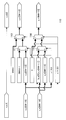
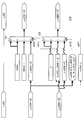
- FIG. 3 is an explanatory diagram illustrating a circuit configuration example of a calculation unit 110.
- FIG. 3 is an explanatory diagram illustrating a circuit configuration example of a calculation unit 110.
- FIG. 3 is an explanatory diagram illustrating a circuit configuration example of a calculation unit 110.
- FIG. 3 is an explanatory diagram illustrating a circuit configuration example of a calculation unit 110.
- FIG. 3 is an explanatory diagram illustrating a circuit configuration example of a calculation unit 110.
- FIG. It is explanatory drawing which shows the effect by using the arithmetic unit 100 which concerns on the same embodiment. It is a block diagram which shows the hardware structural example of the information processing apparatus which concerns on the embodiment.
- Embodiment of the present disclosure [1.1. Overview] Before describing the embodiment of the present disclosure in detail, an outline of the embodiment of the present disclosure will be described.
- the hyperbolic tangent function (tanh) is often used in the field of neural networks.
- the hyperbolic tangent function is a non-linear function, and in order to facilitate the calculation of the hyperbolic tangent function, for example, Patent Documents 1 to 3 disclose techniques for approximating the hyperbolic tangent function by a linear expression or the like.
- circuit scale An operator that increases the circuit scale, such as polynomial approximation or square root function, is required to approximate a hyperbolic tangent function with high accuracy.
- the circuit scale also increases when a hyperbolic tangent function is approximated using a lookup table.
- a hyperbolic tangent function circuit is processed in parallel as an activation function of the neural network, the circuit scale becomes large, so the number of parallel operations cannot be increased.
- the hyperbolic tangent function is roughly approximated by a method such as three-section approximation, the error from the original value of the hyperbolic tangent function increases, and if used as an activation function for a neural network, the error accumulates and the recognition accuracy decreases. Also, the error bias is large.
- the present disclosure has intensively studied a technique that can calculate and approximate a hyperbolic tangent function with high accuracy while having a simple configuration.
- the present disclosure devised a technique that can calculate and approximate a hyperbolic tangent function with high accuracy by a bit operation and a simple bit operation, with a simple configuration. It came.
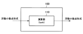
- FIG. 1 is an explanatory diagram illustrating a configuration example of the arithmetic device according to the embodiment of the present disclosure.
- FIG. 1 is an explanatory diagram illustrating a configuration example of the arithmetic device according to the embodiment of the present disclosure.
- a configuration example of the arithmetic device according to the embodiment of the present disclosure will be described with reference to FIG.
- the computing device 100 includes a computing unit 110 that performs a hyperbolic tangent function (tanh) computation.
- the calculation unit 110 may include a CPU (Central Processing Unit), a ROM (Read Only Memory), a RAM (Random Access Memory), and the like.
- the data in the floating point format is input to the calculation unit 110.
- the operation unit 110 performs an operation of a hyperbolic tangent function and outputs floating point format data.
- the arithmetic unit 110 performs an operation using a polygonal line that approximates the hyperbolic tangent function according to a predetermined rule. The rules will be described.
- the hyperbolic tangent function is approximated by a 7-segment line.
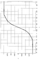
- FIG. 2 is an explanatory diagram showing a hyperbolic tangent function and a polygonal line used by the calculation unit 110 for approximation of the hyperbolic tangent function in the present embodiment.
- the calculation unit 110 outputs the same code y_s as the code x_s of the input x as the code of the output y.
- the sign bit is 0 for positive and 1 for negative.
- the input x has an exponent part x_e, and its bit width is EW.
- EW bit width
- the exponent part x_e when the exponent part x_e is 0, it represents a denormalized number, when the maximum value of all bits of x_e is 1, it represents infinity or a non-number, and otherwise represents a normalized number .
- the input x has a mantissa part x_m, and its bit width is MW.
- MW + 1 bit 1 of the most significant bit (MW + 1 bit) of the original mantissa is omitted. Note that the maximum exponent value expressed by the exponent part is EMAX.
- the polygonal line used by the arithmetic unit 110 to approximate the hyperbolic tangent function is an interval where the input x is between ⁇ 0.5 and 0.5, that is, between ⁇ 2 ⁇ 1 and +2 ⁇ 1. So slope 1, that is, 2 0. Since the broken line in this section passes through the origin, in the section where the input x is between ⁇ 0.5 and 0.5, that is, between ⁇ 2 ⁇ 1 and +2 ⁇ 1 , the calculation unit 110 has the same value as the input x. The output is output as y.
- the calculation unit 110 can directly correspond to an IEEE 754 format denormalized number (exponential part is 0) by outputting the same value as the input x as the output y.
- the slope is 0. 5 or 2-1 .
- FIG. 3 is an explanatory diagram showing a linear expression for each broken line that approximates the hyperbolic tangent function.
- y ⁇ 1 when the input x is ⁇ 2 or less.
- y x / 4 ⁇ 1 / 2
- y x / 2 ⁇ 1 / 4
- the input x is -0.5 to +0.5
- y x
- y 1 when the input x is +2 or more.
- the calculation unit 110 does not use an arithmetic unit for addition / subtraction / multiplication / division, and selects an input x bit rearrangement and a signal generated by only a constant by a selector, thereby performing an approximate calculation of a hyperbolic tangent function. It is characterized by doing.
- D [i] is a 1-bit numerical value (0 or 1) of the i-th bit of the D signal
- D [e: b] is a value expressed by the following equation.
- the section of the input x is determined as follows using the exponent part x_e of x. If the MSB of the exponent part x_e of the input x is 1, it is determined that the absolute value
- the least significant bit (LSB) (LSB) (x_e [0]) of the exponent part x_e of the input x is the most significant bit (MSB) of the mantissa part y_m of the output y
- MSB most significant bit
- the data ⁇ x_e [0], x_m [MW-1: 1] ⁇ obtained by concatenating the remaining bit strings obtained by removing the LSB (x_m [0]) of the mantissa part of the input x is set as the mantissa part y_m of the output y.
- the value of the exponent part of the floating-point format data representing 0.5 is taken as the exponent part y_e of the output y.
- x and y can be expressed by the following mathematical expressions.
- the hyperbolic tangent function is approximated by different linear functions depending on whether the absolute value of the input x is between 0.5 and 1 and between 1 and 2, but the two sections are combined into one operation. be able to.
- the case classification may be performed by the value of the input x instead of the bit determination of the exponent part of the input x.
- the code in that case is as follows.
- the calculation unit 110 can calculate the hyperbolic tangent function by accurately approximating the hyperbolic tangent function by approximating the hyperbolic tangent function to a linear function in this way.
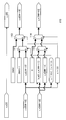
- FIG. 4 is an explanatory diagram illustrating a specific circuit configuration example of the arithmetic unit 110.
- the code x_s [0] of the input x, the exponent part x_e [EW-1: 0] of the input x, and the mantissa part x_m [MW-1: 0] of the input x are input to the arithmetic unit 110 as inputs.
- a state is shown in which a sign y_s [0] of the output y, an exponent part y_e [EW-1: 0] of the output y, and a mantissa part y_m [MW-1: 0] of the output y are output from the arithmetic unit 110 as outputs. ing.
- the code x_s [0] of the input x becomes the code y_s [0] of the output y as it is.
- the selector 111 is a selector configured to output either the exponent part x_e [EW-1: 0] of the input x or EMAX-1.
- the selector 111 receives the result of bit determination of the exponent part of the input x (x_e [EW-2] & x_e [EW-3] & ... & x_e [2] & x_e [1]) are entered.
- the selector 113 is a selector configured to output either the parameter EMAX or the output of the selector 111 to be an exponent part y_e [EW-1: 0] of the output y.
- the selector 113 receives x_e [EW ⁇ 1] which is the MSB of the exponent part x_e of the input x.
- the selector 114 is a selector configured to output either 0 or the output of the selector 112 to obtain the mantissa part y_m [MW-1: 0] of the output y.
- x_e [EW ⁇ 1] that is the MSB of the exponent part x_e of the input x is input to the selector 114.
- the calculation unit 110 includes a block for performing a bit operation, a block for taking a bit sum, and a selector. Therefore, it can be seen that the calculation unit 110 can calculate and approximate the hyperbolic tangent function with high accuracy while having a simple configuration.
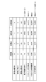
- FIG. 5 is an explanatory diagram showing parameters input to the calculation unit 110 shown in FIG.
- the calculation unit 110 can calculate and approximate the hyperbolic tangent function with high accuracy by changing the parameters.
- the circuit configuration of the arithmetic unit 110 is shown by taking the case of half precision as an example.
- FIG. 6 is an explanatory diagram showing a circuit configuration of the calculation unit 110 that performs an approximate calculation of a hyperbolic tangent function on an input in a half-precision floating point format.
- the bit width EW of the exponent part is 5
- the bit width MW of the mantissa part is 15, and the maximum exponent EMAX is 15 (“01111” when expressed in 5 bits). It is. Therefore, when each parameter is applied to the circuit configuration of the calculation unit 110, the result is as shown in FIG.
- FIGS. 7 to 10 are explanatory diagrams illustrating circuit configuration examples of the arithmetic unit 110.
- FIG. 7 to 10 are explanatory diagrams illustrating circuit configuration examples of the arithmetic unit 110.
- FIG. 7 is a circuit configuration example of the arithmetic unit 110 when the classification is performed based on the value of the input x instead of the bit determination of the exponent part of the input x.
- the selectors 111 and 112 are configured to output “1” if the value of the input x is 0.5 or more, and output “0” if it is less than 0.5.
- the selectors 113 and 114 are configured to output “1” if the value of the input x is 2 or more, and output “0” if it is less than 2.
- FIG. 8 is a circuit configuration example of the arithmetic unit 110 when the case classification is performed based on the value of the input x instead of the bit determination of the exponent part of the input x, as in FIG.
- the selectors 111 and 112 are configured to output “1” if the value of the input x is 0.5 or more, and output “0” if it is less than 0.5.
- the selectors 113 and 114 are configured to output “1” if the value of the input x is 2 or more, and output “0” if it is less than 2.
- the calculation is performed when the classification is performed based on the value of the input x instead of the bit determination of the exponent part of the input x, and the outputs of the selectors 111 and 112 are reversed from the circuit of FIG. 7.
- 3 is a circuit configuration example of a unit 110. That is, the selectors 111 and 112 are configured to output “1” if the value of the input x is less than 0.5, and output “0” if it is 0.5 or more.
- the example of the circuit configuration of the arithmetic unit 110 when the inputs of the selectors 111 to 114 are set to 1 bit has been shown, but the present disclosure is not limited to such an example.
- the input of the selector may be 2 bits.
- FIG. 11 is an explanatory diagram illustrating a circuit configuration example of the arithmetic unit 110.
- FIG. 11 shows an arithmetic unit 110 provided with selectors 121 and 122 that receive 2-bit input.
- the selector 121 determines the result of bit determination of the exponent part of the input x (x_e [EW-2] & x_e [EW-3] & ... & x_e [2] & x_e [1]) is the first bit, and x_e [EW-1] which is the MSB of the exponent x_e of the input x is the second bit. Then, one output is selected according to the input result.
- the selector 121 outputs the parameter EMAX when the second bit (x_e [EW-1]) is 1, and the first bit (x_e [EW-2] & x_e [EW-3] when 0 & ... & x_e [2] & x_e [1]) is 1 if parameter EMAX-1 is output, and if 0, x_m [MW-1: 0] is output.
- the selector 122 determines the result of bit determination of the exponent part of the input x (x_e [EW-2] & x_e [EW-3] & ... & x_e [2] & x_e [1]) is the first bit, and x_e [EW-1] which is the MSB of the exponent x_e of the input x is the second bit. Then, one output is selected according to the input result.
- the second bit (x_e [EW-1]) is 1, the selector 122 outputs 0, and when it is 0, the first bit (x_e [EW-2] & x_e [EW-3] & ...
- & x_e [2] & x_e [1]) are 1 if the bit string ⁇ x_e [0], x_m [MW-1: 1] ⁇ is output, and if 0, x_m [MW-1: 0] is output.
- the arithmetic unit 110 includes a block that performs a bit operation, a block that calculates a bit sum, It can be seen that the hyperbolic tangent function can be approximated with high accuracy and can be calculated with a simple configuration including the selector.
- the configuration of the calculation unit 110 shown in FIG. 11 is divided not by bit determination of the exponent part of the input x but by the value of the input x, as in the modification examples shown in FIGS. Needless to say, the outputs of 122 and 122 may be interchanged.
- the format of data input to the arithmetic unit 110 may be, for example, an inverted bit of the exponent part.
- the arithmetic unit 110 also inverts the bit determination processing in the exponent part described above.
- the format of the data input to the arithmetic unit 110 may be, for example, that a predetermined bit is added to the exponent part in IEEE754.
- the calculation unit 110 can cope with this by changing the value of the parameter EMAX to change the range to be expressed. For example, if 2-bit data is added to the exponent part in IEEE754, the arithmetic part 110 may add 2 to the parameter EMAX.
- the data input to the arithmetic unit 110 is data in the floating point format, but the present disclosure is not limited to such an example.
- the data input to the calculation unit 110 may be data in a fixed point format.
- the arithmetic unit 110 may include a circuit that converts the fixed-point format data into floating-point format data.
- the arithmetic device 100 includes the arithmetic unit 110 including a block that performs a bit operation, a block that takes a bit sum, and a selector, and thus has a simple configuration and a hyperbolic tangent function. Can be approximated with high accuracy. Since the configuration of the calculation unit 110 is simple, for example, even if a plurality of calculation units 110 are mounted and parallel processing is performed, an increase in the circuit scale of the calculation device 100 is small.
- the arithmetic unit 100 has a simple configuration of the arithmetic unit 110, for example, when the arithmetic unit 110 is incorporated in a module that converts data in a fixed-point format into data in a floating-point format But there is no need to add pipeline stages.
- the arithmetic device 100 does not require normalization processing of the mantissa part in the input floating-point format data. Therefore, a circuit for normalization processing (CLZ (Count Leading Zero) circuit or shifter circuit) is not required.
- CLZ Counter Leading Zero
- the arithmetic device 100 approximates a hyperbolic tangent function with a polygonal line whose slope changes in seven sections, compared to a case where the hyperbolic tangent function is approximated with a polygonal line with fewer sections where the slope changes. The accuracy of approximation is greatly improved. In addition, the arithmetic device 100 according to the embodiment of the present disclosure also reduces the error bias in the approximation.
- FIG. 12 is an explanatory diagram illustrating an effect obtained by using the arithmetic device 100 according to the embodiment of the present disclosure.
- FIG. 12 illustrates errors in each of the three-section broken line approximation, the three-section step function approximation, and the seven-section broken line approximation used in the arithmetic device 100 according to the embodiment of the present disclosure.
- Reference numeral 131 indicates an error due to 3-section broken line approximation
- reference numeral 132 indicates an error due to 3-section step function approximation
- reference numeral 133 indicates an error due to 7-section broken line approximation. As shown in FIG.
- the error in the case of the 7-segment broken line approximation used in the arithmetic unit 100, the error is extremely small compared with other approximation methods, and even if an error appears, it appears in both positive and negative directions. An increase in error due to repetition can also be suppressed.
- the arithmetic device 100 according to the embodiment of the present disclosure can automatically cope with a non-normalized number (exponential part is 0) in the IEEE754 format by setting parameters.
- the arithmetic device 100 according to the embodiment of the present disclosure can also be used to obtain an approximation of a sigmoid function ((tanh (x / 2) +1) / 2) using an approximation of a hyperbolic tangent function. That is, tanh (x / 2) / 2 can be calculated only by an operation of subtracting 1 from the exponent part of the input / output to the arithmetic device 100. Therefore, the arithmetic device 100 according to the embodiment of the present disclosure can perform a sigmoid function operation by subtracting 1 from the exponent part of input / output to the arithmetic device 100 and adding 1/2 to the output result. it can.
- FIG. 13 is a block diagram illustrating a hardware configuration example of the information processing apparatus according to the embodiment of the present disclosure.
- the information processing apparatus 900 includes a CPU (Central Processing unit) 901, a ROM (Read Only Memory) 903, and a RAM (Random Access Memory) 905.
- the information processing apparatus 900 may include a host bus 907, a bridge 909, an external bus 911, an interface 913, an input device 915, an output device 917, a storage device 919, a drive 921, a connection port 923, and a communication device 925.
- the information processing apparatus 900 may include an imaging device 933 and a sensor 935 as necessary.
- the information processing apparatus 900 may include a processing circuit such as a DSP (Digital Signal Processor), an ASIC (Application Specific Integrated Circuit), or an FPGA (Field-Programmable Gate Array) instead of or in addition to the CPU 901.
- DSP Digital Signal Processor
- ASIC Application Specific Integrated Circuit
- FPGA Field-Programmable Gate Array
- the CPU 901 functions as an arithmetic processing device and a control device, and controls all or a part of the operation in the information processing device 900 according to various programs recorded in the ROM 903, the RAM 905, the storage device 919, or the removable recording medium 927.
- the ROM 903 stores programs and calculation parameters used by the CPU 901.
- the RAM 905 primarily stores programs used in the execution of the CPU 901, parameters that change as appropriate during the execution, and the like.
- the CPU 901, the ROM 903, and the RAM 905 are connected to each other by a host bus 907 configured by an internal bus such as a CPU bus. Further, the host bus 907 is connected to an external bus 911 such as a PCI (Peripheral Component Interconnect / Interface) bus via a bridge 909.
- PCI Peripheral Component Interconnect / Interface
- the input device 915 is a device operated by the user, such as a mouse, a keyboard, a touch panel, a button, a switch, and a lever.
- the input device 915 may be, for example, a remote control device that uses infrared rays or other radio waves, or may be an external connection device 929 such as a mobile phone that supports the operation of the information processing device 900.
- the input device 915 includes an input control circuit that generates an input signal based on information input by the user and outputs the input signal to the CPU 901. The user operates the input device 915 to input various data and instruct processing operations to the information processing device 900.
- the output device 917 is configured by a device capable of notifying the acquired information to the user using a sense such as vision, hearing, or touch.
- the output device 917 can be, for example, a display device such as an LCD (Liquid Crystal Display) or an organic EL (Electro-Luminescence) display, an audio output device such as a speaker or headphones, or a vibrator.
- the output device 917 outputs the result obtained by the processing of the information processing device 900 as video such as text or image, sound such as sound or sound, or vibration.
- the storage device 919 is a data storage device configured as an example of a storage unit of the information processing device 900.
- the storage device 919 includes, for example, a magnetic storage device such as an HDD (Hard Disk Drive), a semiconductor storage device, an optical storage device, or a magneto-optical storage device.
- the storage device 919 stores, for example, programs executed by the CPU 901 and various data, and various data acquired from the outside.
- the drive 921 is a reader / writer for a removable recording medium 927 such as a magnetic disk, an optical disk, a magneto-optical disk, or a semiconductor memory, and is built in or externally attached to the information processing apparatus 900.
- the drive 921 reads information recorded on the attached removable recording medium 927 and outputs the information to the RAM 905.
- the drive 921 writes a record in the attached removable recording medium 927.
- the connection port 923 is a port for connecting a device to the information processing apparatus 900.
- the connection port 923 can be, for example, a USB (Universal Serial Bus) port, an IEEE 1394 port, a SCSI (Small Computer System Interface) port, or the like.
- the connection port 923 may be an RS-232C port, an optical audio terminal, an HDMI (registered trademark) (High-Definition Multimedia Interface) port, or the like.
- the communication device 925 is a communication interface configured with, for example, a communication device for connecting to the communication network 931.
- the communication device 925 can be, for example, a communication card for LAN (Local Area Network), Bluetooth (registered trademark), Wi-Fi, or WUSB (Wireless USB).
- the communication device 925 may be a router for optical communication, a router for ADSL (Asymmetric Digital Subscriber Line), or a modem for various communication.
- the communication device 925 transmits and receives signals and the like using a predetermined protocol such as TCP / IP with the Internet and other communication devices, for example.
- the communication network 931 connected to the communication device 925 is a network connected by wire or wireless, and may include, for example, the Internet, a home LAN, infrared communication, radio wave communication, satellite communication, or the like.
- the imaging device 933 uses various members such as an imaging element such as a CMOS (Complementary Metal Oxide Semiconductor) or a CCD (Charge Coupled Device), and a lens for controlling the formation of a subject image on the imaging element. It is an apparatus that images a real space and generates a captured image.
- the imaging device 933 may capture a still image or may capture a moving image.
- the sensor 935 is various sensors such as an acceleration sensor, an angular velocity sensor, a geomagnetic sensor, an illuminance sensor, a temperature sensor, an atmospheric pressure sensor, or a sound sensor (microphone).
- the sensor 935 acquires information about the state of the information processing apparatus 900 itself, such as the posture of the information processing apparatus 900, and information about the surrounding environment of the information processing apparatus 900, such as brightness and noise around the information processing apparatus 900, for example. To do.
- the sensor 935 may include a GPS receiver that receives a GPS (Global Positioning System) signal and measures the latitude, longitude, and altitude of the device.
- GPS Global Positioning System
- the arithmetic device 100 can calculate a hyperbolic tangent function by accurately approximating the hyperbolic tangent function with a simple configuration, for example, in the field of neural networks that often use a hyperbolic tangent function. Can be widely used.
- An arithmetic unit approximating with a polygonal line where the slope changes with a power of 2 (k -1, 0, 1) as a boundary;
- the input x and output y are floating point format values;
- the said calculating part is a calculating apparatus which performs the calculation in the several area which has a different inclination in the said broken line with one arithmetic expression.
- the arithmetic unit according to (1) wherein the arithmetic unit generates the output y using bit arithmetic, rearrangement, and a constant for the input x.
- the arithmetic unit includes a first selector that outputs either an exponent part of the input x or a maximum exponent of the input x based on a result of a predetermined bit operation on the exponent part of the input x.
- the arithmetic device according to any one of (1) to (3).
- the arithmetic unit outputs a second selector that outputs one of the maximum exponent of the input x subtracted by 1 and the output of the first selector based on the value of the most significant bit of the exponent part.
- the arithmetic unit according to (4) comprising: (6)
- the arithmetic unit may calculate either the mantissa part of the input x or data obtained by concatenating a bit string other than the least significant bit of the mantissa part of the input x to the least significant bit of the exponent part of the input x.
- the arithmetic unit according to any one of (1) to (5), further including a third selector that outputs based on a result of a predetermined bit operation with respect to the exponent part.
- the arithmetic unit performs a predetermined bit operation on the exponent part of the input x, one of an exponent part of the input x, a maximum exponent of the input x, and a value obtained by subtracting 1 from the maximum exponent of the input x.
- the arithmetic unit according to any one of (1) to (3), further including a first selector that outputs based on a result and a value of the most significant bit of the exponent part of the input x.
- the arithmetic unit is any one of 0, a mantissa part of the input x, and data obtained by concatenating a bit string other than the least significant bit of the mantissa part of the input x to the least significant bit of the exponent part of the input x,
- the input x and output y are floating point format values;
- the input x and output y are floating point format values;
- the computer program which makes the said computer perform the calculation in the some area which has a different inclination in the said broken line with one arithmetic expression.
Landscapes
- Engineering & Computer Science (AREA)
- Physics & Mathematics (AREA)
- General Physics & Mathematics (AREA)
- Theoretical Computer Science (AREA)
- Pure & Applied Mathematics (AREA)
- Mathematical Analysis (AREA)
- Mathematical Optimization (AREA)
- Computational Mathematics (AREA)
- Mathematical Physics (AREA)
- Data Mining & Analysis (AREA)
- General Engineering & Computer Science (AREA)
- Computing Systems (AREA)
- Software Systems (AREA)
- Biophysics (AREA)
- Biomedical Technology (AREA)
- Life Sciences & Earth Sciences (AREA)
- Health & Medical Sciences (AREA)
- Algebra (AREA)
- Databases & Information Systems (AREA)
- Molecular Biology (AREA)
- General Health & Medical Sciences (AREA)
- Evolutionary Computation (AREA)
- Computational Linguistics (AREA)
- Artificial Intelligence (AREA)
- Neurology (AREA)
- Complex Calculations (AREA)
Abstract
【課題】簡易な構成で双曲線正接関数を精度良く近似して演算することが可能な演算装置を提供する。 【解決手段】入力xに対して双曲線正接の演算を行って出力yを出力する双曲線正接関数を、2のn乗(n=-2,-1,0)の傾きを有し、前記入力xの値が±2のk乗(k=-1,0,1)を境界として前記傾きが変わる折れ線で近似する演算部を備え、前記入力x及び出力yは浮動小数点形式の値であり、前記演算部は、前記折れ線における異なる傾きを有する複数の区間における演算を1つの演算式で行う、演算装置が提供される。
Description
本開示は、演算装置、演算方法及びコンピュータプログラムに関する。
ニューラルネットワークの分野においては、双曲線正接関数(tanh)が用いられることが多い。双曲線正接関数は、以下の数式で表される関数であり、例えば所定の閾値を超えたかどうかの判定に用いられる。

双曲線正接関数は非線形な関数であり、双曲線正接関数の演算を容易にするために、例えば特許文献1~3には、双曲線正接関数を一次式などで近似する技術が開示されている。
双曲線正接関数を精度良く近似しようとすると回路規模が大きくなる。ニューラルネットワークの活性化関数として双曲線正接関数の回路を並列処理するような場合には、回路規模が大きくなるので、並列数が大きくできない。その一方、双曲線正接関数を粗く近似すると誤差が大きくなり、ニューラルネットワークの活性化関数として用いると誤差が蓄積されて認識精度が低下する。
そこで、本開示では、簡易な構成で双曲線正接関数を精度良く近似して演算することが可能な、新規かつ改良された演算装置、演算方法及びコンピュータプログラムを提案する。
本開示によれば、入力xに対して双曲線正接の演算を行って出力yを出力する双曲線正接関数を、2のn乗(n=-2,-1,0)の傾きを有し、前記入力xの値が±2のk乗(k=-1,0,1)を境界として前記傾きが変わる折れ線で近似する演算部を備え、前記入力x及び出力yは浮動小数点形式の値であり、前記演算部は、前記折れ線における異なる傾きを有する複数の区間における演算を1つの演算式で行う、演算装置が提供される。
また本開示によれば、プロセッサが、入力xに対して双曲線正接の演算を行って出力yを出力する双曲線正接関数を、2のn乗(n=-2,-1,0)の傾きを有し、2のk乗(k=-1,0,1)の値を境界とする折れ線で近似することを含み、前記入力x及び出力yは浮動小数点形式の値であり、前記プロセッサは、前記折れ線における異なる傾きを有する複数の区間における演算を1つの演算式で行う、演算方法が提供される。
また本開示によれば、コンピュータに、入力xに対して双曲線正接の演算を行って出力yを出力する双曲線正接関数を、2のn乗(n=-2,-1,0)の傾きを有し、2のk乗(k=-1,0,1)の値を境界とする折れ線で近似することを実行させ、前記入力x及び出力yは浮動小数点形式の値であり、前記コンピュータに、前記折れ線における異なる傾きを有する複数の区間における演算を1つの演算式で行わせる、コンピュータプログラムが提供される。
以上説明したように本開示によれば、簡易な構成で双曲線正接関数を精度良く近似して演算することが可能な、新規かつ改良された演算装置、演算方法及びコンピュータプログラムを提供することが出来る。
なお、上記の効果は必ずしも限定的なものではなく、上記の効果とともに、または上記の効果に代えて、本明細書に示されたいずれかの効果、または本明細書から把握され得る他の効果が奏されてもよい。
以下に添付図面を参照しながら、本開示の好適な実施の形態について詳細に説明する。なお、本明細書及び図面において、実質的に同一の機能構成を有する構成要素については、同一の符号を付することにより重複説明を省略する。
なお、説明は以下の順序で行うものとする。
1.本開示の実施の形態
1.1.概要
1.2.構成例
1.3.動作例
1.4.変形例
2.ハードウェア構成例
3.まとめ
1.本開示の実施の形態
1.1.概要
1.2.構成例
1.3.動作例
1.4.変形例
2.ハードウェア構成例
3.まとめ
<1.本開示の実施の形態>
[1.1.概要]
本開示の実施の形態について詳細に説明する前に、本開示の実施の形態の概要について説明する。
[1.1.概要]
本開示の実施の形態について詳細に説明する前に、本開示の実施の形態の概要について説明する。
上述したように、ニューラルネットワークの分野においては、双曲線正接関数(tanh)が用いられることが多い。双曲線正接関数は非線形な関数であり、双曲線正接関数の演算を容易にするために、例えば特許文献1~3には、双曲線正接関数を一次式などで近似する技術が開示されている。
双曲線正接関数を精度良く近似しようとすると、多項式近似や平方根関数など回路規模が大きくなる演算器が必要となる。ルックアップテーブルを使って双曲線正接関数を近似する場合も回路規模が大きくなる。ニューラルネットワークの活性化関数として双曲線正接関数の回路を並列処理するような場合には、回路規模が大きくなるので、並列数が大きくできない。
その一方、3区間近似などの手法により双曲線正接関数を粗く近似すると、双曲線正接関数の本来の値との誤差が大きくなり、ニューラルネットワークの活性化関数として用いると誤差が蓄積されて認識精度が下がり、また誤差の偏りも大きい。
そこで本件開示者は、上述した点に鑑みて、簡易な構成でありながら、双曲線正接関数を精度良く近似して演算することが出来る技術について鋭意検討を行った。その結果、本件開示者は、以下で説明するように、ビット操作と簡単なビット演算によって、簡易な構成でありながら、双曲線正接関数を精度良く近似して演算することが出来る技術を考案するに至った。
以上、本開示の実施の形態の概要について説明した。続いて、本開示の実施の形態について詳細に説明する。
[1.2.構成例]
図1は、本開示の実施の形態に係る演算装置の構成例を示す説明図である。以下、図1を用いて本開示の実施の形態に係る演算装置の構成例について説明する。
図1は、本開示の実施の形態に係る演算装置の構成例を示す説明図である。以下、図1を用いて本開示の実施の形態に係る演算装置の構成例について説明する。
本開示の実施の形態に係る演算装置100は、双曲線正接関数(tanh)の演算を行う演算部110を含んで構成される。演算部110は、CPU(Central Processing Unit)やROM(Read Only Memory)、RAM(Random Access Memory)などを含んで構成されうる。
演算部110には、浮動小数点形式のデータが入力される。演算部110は、双曲線正接関数の演算を行って、浮動小数点形式のデータを出力する。演算部110は、双曲線正接関数の演算を行う際に、所定のルールで双曲線正接関数を近似した折れ線を用いた演算を行う。そのルールについて説明する。
本実施形態では、双曲線正接関数は、7区間の折れ線で近似する。その傾きは2のn乗(n=-1、0、1)であり、2のk乗(k=-2、-1、0)の値を境界とする入力区間で近似する。図2は、双曲線正接関数と、本実施形態で演算部110が双曲線正接関数の近似に用いる折れ線とを示す説明図である。
図2に示したように、双曲線正接関数は、xが正の場合はyが正であり、xが負の場合はyは負である。従って演算部110は、入力xの符号x_sと同じ符号y_sを出力yの符号として出力する。なお、符号ビットは0で正を、1で負を表す。
入力xは、指数部x_eを有し、そのビット幅はEWである。IEEE754形式では、指数部x_eが0の場合に非正規化数を表し、x_eの全ビットが1である最大値の場合に無限大か非数を表し、それ以外の場合に正規化数を表す。また入力xは、仮数部x_mを有し、そのビット幅はMWである。IEEE754形式では、正規化数の場合、本来の仮数の最上位ビット(MW+1ビット目)の1が省略されている。なお、指数部が表現する最大の指数値をEMAXとする。
IEEE754形式で表現する値は、半精度の場合は(-1)x_s×2x_e-15×(1+x_m/210)、単精度の場合は(-1)x_s×2x_e-127×(1+x_m/223)、倍精度の場合は(-1)x_s×2x_e-1023×(1+x_m/252)、4倍精度の場合は(-1)x_s×2x_e-16383×(1+x_m/2112)である。
また図2に示したように、演算部110が双曲線正接関数の近似に用いる折れ線は、入力xが-0.5~0.5の間、すなわち-2-1~+2-1の間の区間では、傾きが1、すなわち20である。この区間の折れ線は原点を通るため、入力xが-0.5~0.5の間、すなわち-2-1~+2-1の間の区間では、演算部110は、入力xと同じ値を出力yとして出力することになる。演算部110は、入力xと同じ値を出力yとして出力することで、IEEE754形式の非正規化数(指数部が0)にそのまま対応できる。
また入力xが-1~-0.5の間及び0.5~1の間、すなわち-20~-2-1の間及び+2-1~+20の間の区間では、傾きが0.5、すなわち2-1である。また入力xが-2~-1の間及び1~2の間、すなわち-21~-20の間及び+20~+21の間の区間では、傾きが0.25、すなわち2-2である。なお、入力xが-2以下の場合はy=-1であり、入力xが2以上の場合はy=1である。
図3は、双曲線正接関数を近似する折れ線のそれぞれについての一次式を表した説明図である。入力xが-2以下の場合はy=-1であるのは上述した通りである。また、入力xが-2~-1の場合はy=x/4-1/2であり、入力xが-1~-0.5の場合はy=x/2-1/4であり、入力xが-0.5~+0.5の場合はy=xであり、入力xが+0.5~+1の場合はy=x/2+1/4であり、入力xが+1~+2の場合はy=x/4+1/2である。入力xが+2以上の場合はy=1であるのは上述した通りである。
そして本実施形態に係る演算部110は、加減乗除の演算器を用いず、入力xのビットの並び替えと、定数のみで作る信号とをセレクタで選択することにより、双曲線正接関数の近似演算を行うことを特徴としている。以下の説明では、D[i]をD信号のiビット目の1ビットの数値(0または1)とし、D[e:b]は以下の数式で表した値とする。

また、入力xの区間を、xの指数部x_eを用いて以下のように判定する。入力xの指数部x_eのMSBが1なら、入力xの絶対値|x|が|x|≧2の区間と判定する。また入力xの指数部x_eのMSBが0で、かつ入力xの指数部x_eのMSBとLSBとの間の各ビットが全て1なら、入力xの絶対値|x|が2>|x|≧0.5の区間と判定する。また、入力xの指数部x_eのMSBが0で、かつ入力xの指数部x_eのMSBとLSBとの間のビットに0が1つ以上含まれるなら、入力xの絶対値|x|が0.5≧|x|≧0の区間と判定する。
(1)入力xの絶対値が2以上の区間の場合
入力xの絶対値が2以上の区間の場合は、yは+1または-1である。従って、この場合は1を表現する浮動小数点形式データの仮数部の値を出力yの仮数部y_mとし、1を表現する浮動小数点形式データの指数部の値を出力yの指数部y_eとする。
入力xの絶対値が2以上の区間の場合は、yは+1または-1である。従って、この場合は1を表現する浮動小数点形式データの仮数部の値を出力yの仮数部y_mとし、1を表現する浮動小数点形式データの指数部の値を出力yの指数部y_eとする。
(2)入力xの絶対値が0.5以上2未満の区間の場合
本実施形態では、入力xの絶対値が0.5~1の間と、1~2の間とで、それぞれ異なる一次関数で双曲線正接関数を近似するが、この2つの区間を1つにまとめて演算することができる。
本実施形態では、入力xの絶対値が0.5~1の間と、1~2の間とで、それぞれ異なる一次関数で双曲線正接関数を近似するが、この2つの区間を1つにまとめて演算することができる。
入力xの絶対値が0.5以上2未満の区間の場合、入力xの指数部x_eの最下位ビット(LSB)(x_e[0])を出力yの仮数部y_mの最上位ビット(MSB)とし、入力xの仮数部のLSB(x_m[0])を削った残りのビット列を連結したデータ{x_e[0],x_m[MW-1:1]}を出力yの仮数部y_mとする。また、0.5を表現する浮動小数点形式データの指数部の値を、出力yの指数部y_eとする。
すなわち、y_m={x_e[0],x_m[MW-1:1]}であり、y_e=EMAX-1であり、y_s=x_sである。言い換えれば、x及びyは以下の数式で表すことが出来る。
x=(-1)x_s・2x_e-EMAX・(2MW+x_m[MW-1:0])/2MW
=(-1)x_s・2x_e-EMAX・(1+x_m[MW-1:0]/2MW)
=(-1)x_s・2x_e-EMAX・(1+x_m[MW-1:0]/2MW)
y=(-1)y_s・2y_e-EMAX・(2MW+y_m[MW-1:0])/2MW
=(-1)x_s・2-1・(2MW+x_e[0]2MW-1+x_m[MW-1:1])/2MW
=(-1)x_s・(1/2+x_e[0]2-2+x_m[MW-1:1]2-2/2MW-1)
=(-1)x_s・(1/2+(x_e[0]+x_m[MW-1:1]/2MW-1)/4)
=(-1)x_s・2-1・(2MW+x_e[0]2MW-1+x_m[MW-1:1])/2MW
=(-1)x_s・(1/2+x_e[0]2-2+x_m[MW-1:1]2-2/2MW-1)
=(-1)x_s・(1/2+(x_e[0]+x_m[MW-1:1]/2MW-1)/4)
入力xの指数部x_e=EMAX(x_e[0]=1)の場合、すなわちy=x/4±1/2の区間では、x及びyは以下の数式で表すことが出来る。
x=(-1)x_s・(1+x_m[MW-1:0]/2MW)
y=(-1)x_s・(1/2+(1+x_m[MW-1:1]/2MW-1)/4)
≒(-1)x_s・(1/2+(1+x_m[MW-1:0]/2MW)/4)
=(-1)x_s・1/2+(-1)-x_s・(1+x_m[MW-1:0]/2MW)/4
=(-1)x_s/2+x/4
≒(-1)x_s・(1/2+(1+x_m[MW-1:0]/2MW)/4)
=(-1)x_s・1/2+(-1)-x_s・(1+x_m[MW-1:0]/2MW)/4
=(-1)x_s/2+x/4
また、入力xの指数部x_e=EMAX(x_e[0]=0)の場合、すなわちy=x/4±1/2の区間では、x及びyは以下の数式で表すことが出来る。
x=(-1)x_s・2-1・(1+x_m[MW-1:0]/2MW)
=(-1)x_s・(1/2+x_m[MW-1:0]/2MW+1)
=(-1)x_s・(1/2+x_m[MW-1:0]/2MW+1)
y=(-1)x_s・(1/2+(0+x_m[MW-1:1]/2MW-1)/4)
=(-1)x_s・(1/2+x_m[MW-1:1]/2MW+1)
≒(-1)x_s・(1/2+x_m[MW-1:0]/2MW+1/2
=(-1)x_s・(1/4+(1/2+x_m[MW-1:0]/2MW+1)/2)
=(-1)-x_s・1/4+(-1)-x_s・(1/2+x_m[MW-1:0]/2MW+1)/2
=(-1)x_s/4+x/2
=(-1)x_s・(1/2+x_m[MW-1:1]/2MW+1)
≒(-1)x_s・(1/2+x_m[MW-1:0]/2MW+1/2
=(-1)x_s・(1/4+(1/2+x_m[MW-1:0]/2MW+1)/2)
=(-1)-x_s・1/4+(-1)-x_s・(1/2+x_m[MW-1:0]/2MW+1)/2
=(-1)x_s/4+x/2
従って、入力xの絶対値が0.5~1の間と、1~2の間とで、それぞれ異なる一次関数で双曲線正接関数を近似するが、この2つの区間を1つにまとめて演算することができる。
(3)入力xの絶対値が0以上0.5未満の区間の場合
入力xの絶対値が0以上0.5未満の区間の場合は、入力xの仮数部x_mを出力yの仮数部y_mとする。つまり、y_m=x_mである。また、入力xの指数部x_eを出力yの指数部y_eとする。つまりy_e=x_eである。すなわち上述したように、入力xの絶対値が0以上0.5未満の区間の場合は、入力xをそのまま出力yとする。
入力xの絶対値が0以上0.5未満の区間の場合は、入力xの仮数部x_mを出力yの仮数部y_mとする。つまり、y_m=x_mである。また、入力xの指数部x_eを出力yの指数部y_eとする。つまりy_e=x_eである。すなわち上述したように、入力xの絶対値が0以上0.5未満の区間の場合は、入力xをそのまま出力yとする。
以上を踏まえて、演算部110による、双曲線正接関数の近似演算を擬似的にコードで現すと以下の通りとなる。
if(x_e[EW-1]){
y_e = EMAX
y_m = 0
}else
if(x_e[EW-2] & x_e[EW-3] & ... & x_e[2] & x_e[1]){
y_e = EMAX-1
y_m = {x_e[0],x_m[9:1]}
}else{
y_e = x_e
y_m = x_m
}
y_s =
x_s
y_e = EMAX
y_m = 0
}else
if(x_e[EW-2] & x_e[EW-3] & ... & x_e[2] & x_e[1]){
y_e = EMAX-1
y_m = {x_e[0],x_m[9:1]}
}else{
y_e = x_e
y_m = x_m
}
y_s =
x_s
場合分けを入力xの指数部のビット判定ではなく入力xの値で行っても良い。その場合のコードは以下の通りとなる。
if(x >= 2.0){
y_e = EMAX
y_m = 0
}else
if(x >= 0.5){
y_e = EMAX-1
y_m = {x_e[0],x_m[9:1]}
}else{
y_e = x_e
y_m = x_m
}
y_s =
x_s
y_e = EMAX
y_m = 0
}else
if(x >= 0.5){
y_e = EMAX-1
y_m = {x_e[0],x_m[9:1]}
}else{
y_e = x_e
y_m = x_m
}
y_s =
x_s
このように演算部110は、このように双曲線正接関数を一次関数に近似して演算することで、簡易な構成でありながら、双曲線正接関数を精度良く近似して演算することができる。
続いて、演算部110の具体的な回路構成例を説明する。
図4は、演算部110の具体的な回路構成例を示す説明図である。図4は、入力として入力xの符号x_s[0]、入力xの指数部x_e[EW-1:0]、入力xの仮数部x_m[MW-1:0]が演算部110に入力され、出力として出力yの符号y_s[0]、出力yの指数部y_e[EW-1:0]、出力yの仮数部y_m[MW-1:0]が演算部110から出力される様子が示されている。
上述したように、入力xの符号x_s[0]は、そのまま出力yの符号y_s[0]となる。
セレクタ111は、入力xの指数部x_e[EW-1:0]と、EMAX-1とのいずれかを出力するよう構成されるセレクタである。セレクタ111には、入力xの指数部のビット判定の結果(x_e[EW-2] & x_e[EW-3]
& ... & x_e[2] & x_e[1])が入力される。セレクタ111は、x_e[EW-2] &
x_e[EW-3] & ... & x_e[2] & x_e[1]=1の場合は、EMAX-1を出力し、0の場合はx_e[EW-1:0]を出力する。
& ... & x_e[2] & x_e[1])が入力される。セレクタ111は、x_e[EW-2] &
x_e[EW-3] & ... & x_e[2] & x_e[1]=1の場合は、EMAX-1を出力し、0の場合はx_e[EW-1:0]を出力する。
セレクタ112は、ビット列{x_e[0],x_m[MW-1:1]}か、入力xの仮数部x_m[MW-1:0]のいずれかを出力するよう構成されるセレクタである。セレクタ112には、セレクタ111同様に、入力xの指数部のビット判定の結果(x_e[EW-2] & x_e[EW-3]
& ... & x_e[2] & x_e[1])が入力される。セレクタ112は、x_e[EW-2] &
x_e[EW-3] & ... & x_e[2] & x_e[1]=1の場合は、ビット列{x_e[0],x_m[MW-1:1]}を出力し、0の場合はx_m[MW-1:0]を出力する。
& ... & x_e[2] & x_e[1])が入力される。セレクタ112は、x_e[EW-2] &
x_e[EW-3] & ... & x_e[2] & x_e[1]=1の場合は、ビット列{x_e[0],x_m[MW-1:1]}を出力し、0の場合はx_m[MW-1:0]を出力する。
セレクタ113は、パラメータEMAXと、セレクタ111の出力とのいずれかを出力して、出力yの指数部y_e[EW-1:0]とするよう構成されるセレクタである。セレクタ113には、入力xの指数部x_eのMSBであるx_e[EW-1]が入力される。セレクタ113は、x_e[EW-1]=1の場合は、パラメータEMAXを出力し、0の場合は、セレクタ111の出力を出力する。
セレクタ114は、0と、セレクタ112の出力とのいずれかを出力して、出力yの仮数部y_m[MW-1:0]とするよう構成されるセレクタである。セレクタ114には、セレクタ113と同様に、入力xの指数部x_eのMSBであるx_e[EW-1]が入力される。セレクタ114は、x_e[EW-1]=1の場合は0を出力し、1の場合は、セレクタ113の出力を出力する。
このように、演算部110は、ビット操作を行うブロックと、ビット和を取るブロックと、セレクタとで構成される。従って、演算部110は、簡易な構成でありながら、双曲線正接関数を精度良く近似して演算することができることがわかる。
図5は、図4に示した演算部110に入力されるパラメータを示す説明図である。半精度、単精度、倍精度、四倍精度の場合で、それぞれパラメータを変えることで、演算部110は双曲線正接関数を精度良く近似して演算することができる。以下では、半精度の場合を例に挙げて演算部110の回路構成を示す。
図6は、半精度浮動小数点形式の入力に対して双曲線正接関数の近似演算を行う演算部110の回路構成を示す説明図である。図5に示したように、半精度浮動小数点形式の場合は、指数部のビット幅EWは5,仮数部のビット幅MWは15、最大指数EMAXは15(5ビットで表すと「01111」)である。従って、それぞれのパラメータを演算部110の回路構成に当てはめると図6に示した通りとなる。
演算部110の回路構成は図4に示したものに限定されない。図7~10は、演算部110の回路構成例を示す説明図である。
図7は、場合分けを入力xの指数部のビット判定ではなく入力xの値で行う場合の、演算部110の回路構成例である。この場合、セレクタ111、112は、入力xの値が0.5以上であれば「1」の方を出力し、0.5未満であれば「0」の方を出力するよう構成される。またセレクタ113、114は、入力xの値が2以上であれば「1」の方を出力し、2未満であれば「0」の方を出力するよう構成される。
図8は、図7と同様に、場合分けを入力xの指数部のビット判定ではなく入力xの値で行う場合の、演算部110の回路構成例である。この場合、セレクタ111、112は、入力xの値が0.5以上であれば「1」の方を出力し、0.5未満であれば「0」の方を出力するよう構成される。またセレクタ113、114は、入力xの値が2以上であれば「1」の方を出力し、2未満であれば「0」の方を出力するよう構成される。
図9は、図7と同様に、場合分けを入力xの指数部のビット判定ではなく入力xの値で行い、かつ図7の回路からセレクタ111、112の出力を逆にした場合の、演算部110の回路構成例である。すなわち、セレクタ111、112は、入力xの値が0.5未満であれば「1」の方を出力し、0.5以上であれば「0」の方を出力するよう構成される。
図10は、入力xが0.5以上かどうかの場合分けを別のビット判定({x_e[EW-2:1],1’b1}==EMAX)で行う場合の、演算部110の回路構成例である。セレクタ111、112は、{x_e[EW-2:1],1’b1}==EMAXであれば「1」の方を出力し、{x_e[EW-2:1],1’b1}==EMAXでなければ「0」の方を出力するよう構成される。
ここまでは、セレクタ111~114の入力を1ビットにした場合の演算部110の回路構成例を示したが、本開示は係る例に限定されるものではない。セレクタの入力は2ビットであってもよい。
図11は、演算部110の回路構成例を示す説明図である。図11には、2ビットの入力を受けるセレクタ121、122が設けられた演算部110が示されている。
セレクタ121は、入力xの指数部のビット判定の結果(x_e[EW-2] & x_e[EW-3]
& ... & x_e[2] & x_e[1])を1ビット目、入力xの指数部x_eのMSBであるx_e[EW-1]を2ビット目の入力とした2ビットの入力を受けて、その入力結果に応じて1つの出力を選択する。セレクタ121は、2ビット目(x_e[EW-1])が1の場合は、パラメータEMAXを出力し、0の場合は、1ビット目(x_e[EW-2] & x_e[EW-3]
& ... & x_e[2] & x_e[1])が1であればパラメータEMAX-1を出力し、0であればx_m[MW-1:0]を出力する。
& ... & x_e[2] & x_e[1])を1ビット目、入力xの指数部x_eのMSBであるx_e[EW-1]を2ビット目の入力とした2ビットの入力を受けて、その入力結果に応じて1つの出力を選択する。セレクタ121は、2ビット目(x_e[EW-1])が1の場合は、パラメータEMAXを出力し、0の場合は、1ビット目(x_e[EW-2] & x_e[EW-3]
& ... & x_e[2] & x_e[1])が1であればパラメータEMAX-1を出力し、0であればx_m[MW-1:0]を出力する。
セレクタ122は、セレクタ121と同様に入力xの指数部のビット判定の結果(x_e[EW-2] & x_e[EW-3]
& ... & x_e[2] & x_e[1])を1ビット目、入力xの指数部x_eのMSBであるx_e[EW-1]を2ビット目の入力とした2ビットの入力を受けて、その入力結果に応じて1つの出力を選択する。セレクタ122は、2ビット目(x_e[EW-1])が1の場合は、0を出力し、0の場合は、1ビット目(x_e[EW-2] & x_e[EW-3]
& ... & x_e[2] & x_e[1])が1であればビット列{x_e[0],x_m[MW-1:1]}を出力し、0の場合はx_m[MW-1:0]を出力する。
& ... & x_e[2] & x_e[1])を1ビット目、入力xの指数部x_eのMSBであるx_e[EW-1]を2ビット目の入力とした2ビットの入力を受けて、その入力結果に応じて1つの出力を選択する。セレクタ122は、2ビット目(x_e[EW-1])が1の場合は、0を出力し、0の場合は、1ビット目(x_e[EW-2] & x_e[EW-3]
& ... & x_e[2] & x_e[1])が1であればビット列{x_e[0],x_m[MW-1:1]}を出力し、0の場合はx_m[MW-1:0]を出力する。
このように、2ビットの信号を入力して入力した信号に応じて出力を選択するセレクタ121、122を備えることによっても、演算部110は、ビット操作を行うブロックと、ビット和を取るブロックと、セレクタと、を備える簡易な構成でありながら、双曲線正接関数を精度良く近似して演算することができることがわかる。
なお、図11に示した演算部110の構成を、図7~10等に示す変形例のように、場合分けを入力xの指数部のビット判定ではなく入力xの値で行ったり、セレクタ121、122の出力を入れ替えたりするものとしてもよいことは言うまでもない。
演算部110に入力されるデータの形式は、例えば指数部のビットが反転されたものであってもよい。指数部のビットが反転されている場合は、演算部110では、上述した指数部におけるビット判定処理も反転することになる。
演算部110に入力されるデータの形式は、例えばIEEE754における指数部に所定のビットが付加されたようなものであってもよい。この場合は、演算部110では、パラメータEMAXの値を変更して、表現するレンジを変化させることで対応することが可能となる。例えばIEEE754における指数部に2ビットデータが付加されていれば、演算部110では、パラメータEMAXに2を追加すれば良い。
上述の説明では、演算部110に入力されるデータは浮動小数点形式のデータであるとしたが、本開示は係る例に限定されるものではない。例えば、演算部110に入力されるデータは固定小数点形式のデータであってもよい。固定小数点形式のデータが入力される場合、演算部110は、固定小数点形式のデータを浮動小数点形式のデータに変換する回路を備えていても良い。
本開示の実施の形態に係る演算装置100は、ビット操作を行うブロックと、ビット和を取るブロックと、セレクタと、を備える演算部110を有することにより、簡易な構成でありながらも双曲線正接関数を精度良く近似して演算することができる。演算部110の構成が簡易なものであるため、例えば演算部110を複数搭載して並列処理をさせても、演算装置100の回路規模の増加が少なく済む。
本開示の実施の形態に係る演算装置100は、演算部110の構成が簡易なものであるため、例えば固定小数点形式のデータを浮動小数点形式のデータに変換するモジュールに演算部110を組み込んだ場合でもパイプラインのステージ追加が不要である。
本開示の実施の形態に係る演算装置100は、入力される浮動小数点形式のデータにおける仮数部の正規化処理が不要である。従って、正規化処理のための回路(CLZ(Count Leading Zero)回路やシフタ回路)が不要となる。
本開示の実施の形態に係る演算装置100は、7区間で傾きが変わる折れ線で双曲線正接関数を近似するために、これより傾きが変わる区間が少ない折れ線で双曲線正接関数を近似する場合に比べて近似の精度が大きく向上する。また本開示の実施の形態に係る演算装置100は、近似の際の誤差の偏りも少なくなる。
図12は、本開示の実施の形態に係る演算装置100を用いることによる効果を示す説明図である。図12には、3区間折れ線近似、3区間階段関数近似、そして本開示の実施の形態に係る演算装置100で用いる7区間折れ線近似のそれぞれにおける誤差が示されている。符号131が3区間折れ線近似による誤差を示し、符号132が3区間階段関数近似による誤差を示し、符号133が7区間折れ線近似による誤差を示している。図12に示したように、演算装置100で用いる7区間折れ線近似の場合は、他の近似方法に比べて誤差が極めて小さく、また誤差が現れたとしても正負双方に現れているので、近似を繰り返すことによる誤差の増大も抑えることができる。
本開示の実施の形態に係る演算装置100は、パラメータの設定により、IEEE754形式の非正規化数(指数部が0)にも自動的に対応することが出来る。また本開示の実施の形態に係る演算装置100は、シグモイド関数((tanh(x/2)+1)/2)の近似を、双曲線正接関数の近似を使って求めることにも使える。すなわち、tanh(x/2)/2は、演算装置100への入出力の指数部から1を減じる操作のみで演算することができる。従って、本開示の実施の形態に係る演算装置100は、演算装置100への入出力の指数部から1を減じ、出力結果に1/2を加算することで、シグモイド関数の演算を行うことができる。
<2.ハードウェア構成例>
次に、図13を参照して、本開示の実施形態に係る演算装置100が設けられる情報処理装置のハードウェア構成について説明する。図13は、本開示の実施形態に係る情報処理装置のハードウェア構成例を示すブロック図である。
次に、図13を参照して、本開示の実施形態に係る演算装置100が設けられる情報処理装置のハードウェア構成について説明する。図13は、本開示の実施形態に係る情報処理装置のハードウェア構成例を示すブロック図である。
情報処理装置900は、CPU(Central Processing unit)901、ROM(Read Only Memory)903、およびRAM(Random Access Memory)905を含む。また、情報処理装置900は、ホストバス907、ブリッジ909、外部バス911、インターフェース913、入力装置915、出力装置917、ストレージ装置919、ドライブ921、接続ポート923、通信装置925を含んでもよい。さらに、情報処理装置900は、必要に応じて、撮像装置933、およびセンサ935を含んでもよい。情報処理装置900は、CPU901に代えて、またはこれとともに、DSP(Digital Signal Processor)、ASIC(Application Specific Integrated Circuit)、またはFPGA(Field-Programmable Gate Array)などの処理回路を有してもよい。
CPU901は、演算処理装置および制御装置として機能し、ROM903、RAM905、ストレージ装置919、またはリムーバブル記録媒体927に記録された各種プログラムに従って、情報処理装置900内の動作全般またはその一部を制御する。ROM903は、CPU901が使用するプログラムや演算パラメータなどを記憶する。RAM905は、CPU901の実行において使用するプログラムや、その実行において適宜変化するパラメータなどを一次記憶する。CPU901、ROM903、およびRAM905は、CPUバスなどの内部バスにより構成されるホストバス907により相互に接続されている。さらに、ホストバス907は、ブリッジ909を介して、PCI(Peripheral Component Interconnect/Interface)バスなどの外部バス911に接続されている。
入力装置915は、例えば、マウス、キーボード、タッチパネル、ボタン、スイッチおよびレバーなど、ユーザによって操作される装置である。入力装置915は、例えば、赤外線やその他の電波を利用したリモートコントロール装置であってもよいし、情報処理装置900の操作に対応した携帯電話などの外部接続機器929であってもよい。入力装置915は、ユーザが入力した情報に基づいて入力信号を生成してCPU901に出力する入力制御回路を含む。ユーザは、この入力装置915を操作することによって、情報処理装置900に対して各種のデータを入力したり処理動作を指示したりする。
出力装置917は、取得した情報をユーザに対して視覚や聴覚、触覚などの感覚を用いて通知することが可能な装置で構成される。出力装置917は、例えば、LCD(Liquid Crystal Display)または有機EL(Electro-Luminescence)ディスプレイなどの表示装置、スピーカまたはヘッドフォンなどの音声出力装置、もしくはバイブレータなどでありうる。出力装置917は、情報処理装置900の処理により得られた結果を、テキストもしくは画像などの映像、音声もしくは音響などの音声、またはバイブレーションなどとして出力する。
ストレージ装置919は、情報処理装置900の記憶部の一例として構成されたデータ格納用の装置である。ストレージ装置919は、例えば、HDD(Hard Disk Drive)などの磁気記憶部デバイス、半導体記憶デバイス、光記憶デバイス、または光磁気記憶デバイスなどにより構成される。ストレージ装置919は、例えばCPU901が実行するプログラムや各種データ、および外部から取得した各種のデータなどを格納する。
ドライブ921は、磁気ディスク、光ディスク、光磁気ディスク、または半導体メモリなどのリムーバブル記録媒体927のためのリーダライタであり、情報処理装置900に内蔵、あるいは外付けされる。ドライブ921は、装着されているリムーバブル記録媒体927に記録されている情報を読み出して、RAM905に出力する。また、ドライブ921は、装着されているリムーバブル記録媒体927に記録を書き込む。
接続ポート923は、機器を情報処理装置900に接続するためのポートである。接続ポート923は、例えば、USB(Universal Serial Bus)ポート、IEEE1394ポート、SCSI(Small Computer System Interface)ポートなどでありうる。また、接続ポート923は、RS-232Cポート、光オーディオ端子、HDMI(登録商標)(High-Definition Multimedia Interface)ポートなどであってもよい。接続ポート923に外部接続機器929を接続することで、情報処理装置900と外部接続機器929との間で各種のデータが交換されうる。
通信装置925は、例えば、通信ネットワーク931に接続するための通信デバイスなどで構成された通信インターフェースである。通信装置925は、例えば、LAN(Local Area Network)、Bluetooth(登録商標)、Wi-Fi、またはWUSB(Wireless USB)用の通信カードなどでありうる。また、通信装置925は、光通信用のルータ、ADSL(Asymmetric Digital Subscriber Line)用のルータ、または、各種通信用のモデムなどであってもよい。通信装置925は、例えば、インターネットや他の通信機器との間で、TCP/IPなどの所定のプロトコルを用いて信号などを送受信する。また、通信装置925に接続される通信ネットワーク931は、有線または無線によって接続されたネットワークであり、例えば、インターネット、家庭内LAN、赤外線通信、ラジオ波通信または衛星通信などを含みうる。
撮像装置933は、例えば、CMOS(Complementary Metal Oxide Semiconductor)またはCCD(Charge Coupled Device)などの撮像素子、および撮像素子への被写体像の結像を制御するためのレンズなどの各種の部材を用いて実空間を撮像し、撮像画像を生成する装置である。撮像装置933は、静止画を撮像するものであってもよいし、また動画を撮像するものであってもよい。
センサ935は、例えば、加速度センサ、角速度センサ、地磁気センサ、照度センサ、温度センサ、気圧センサ、または音センサ(マイクロフォン)などの各種のセンサである。センサ935は、例えば情報処理装置900の筐体の姿勢など、情報処理装置900自体の状態に関する情報や、情報処理装置900の周辺の明るさや騒音など、情報処理装置900の周辺環境に関する情報を取得する。また、センサ935は、GPS(Global Positioning System)信号を受信して装置の緯度、経度および高度を測定するGPS受信機を含んでもよい。
以上、情報処理装置900のハードウェア構成の一例を示した。なお、情報処理装置900のハードウェア構成は、実施する時々の技術レベルに応じて適宜変更されうる。
<3.まとめ>
以上説明したように、本開示の実施の形態によれば、簡易な構成でありながらも双曲線正接関数を精度良く近似して演算することができる演算装置100が提供される。
以上説明したように、本開示の実施の形態によれば、簡易な構成でありながらも双曲線正接関数を精度良く近似して演算することができる演算装置100が提供される。
本開示の実施の形態に係る演算装置100は、簡易な構成でありながら双曲線正接関数を精度良く近似して演算することができるので、例えば、双曲線正接関数を用いることが多いニューラルネットワークの分野で幅広く活用されうる。
各装置に内蔵されるCPU、ROMおよびRAMなどのハードウェアを、上述した各装置の構成と同等の機能を発揮させるためのコンピュータプログラムも作成可能である。また、該コンピュータプログラムを記憶させた記憶媒体も提供されることが可能である。また、機能ブロック図で示したそれぞれの機能ブロックをハードウェアで構成することで、一連の処理をハードウェアで実現することもできる。
以上、添付図面を参照しながら本開示の好適な実施形態について詳細に説明したが、本開示の技術的範囲はかかる例に限定されない。本開示の技術分野における通常の知識を有する者であれば、特許請求の範囲に記載された技術的思想の範疇内において、各種の変更例または修正例に想到し得ることは明らかであり、これらについても、当然に本開示の技術的範囲に属するものと了解される。
また、本明細書に記載された効果は、あくまで説明的または例示的なものであって限定的ではない。つまり、本開示に係る技術は、上記の効果とともに、または上記の効果に代えて、本明細書の記載から当業者には明らかな他の効果を奏しうる。
なお、以下のような構成も本開示の技術的範囲に属する。
(1)
入力xに対して双曲線正接の演算を行って出力yを出力する双曲線正接関数を、2のn乗(n=-2,-1,0)の傾きを有し、前記入力xの値が±2のk乗(k=-1,0,1)を境界として前記傾きが変わる折れ線で近似する演算部を備え、
前記入力x及び出力yは浮動小数点形式の値であり、
前記演算部は、前記折れ線における異なる傾きを有する複数の区間における演算を1つの演算式で行う、演算装置。
(2)
前記演算部は、前記入力xに対するビットの演算並びに並び替え及び定数を用いて前記出力yを生成する、前記(1)に記載の演算装置。
(3)
前記演算部は、前記kの値が-1~1の間の区間における演算を1つの演算式で行う、前記(1)または(2)に記載の演算装置。
(4)
前記演算部は、前記入力xの指数部と、前記入力xの最大指数とのいずれかを、前記入力xの指数部に対する所定のビット演算の結果に基づいて出力する第1のセレクタを備える、前記(1)~(3)のいずれかに記載の演算装置。
(5)
前記演算部は、前記入力xの最大指数から1減算したものと、前記第1のセレクタの出力とのいずれかを、前記指数部の最上位ビットの値に基づいて出力する第2のセレクタを備える、前記(4)に記載の演算装置。
(6)
前記演算部は、前記入力xの仮数部と、前記入力xの指数部の最下位ビットに前記入力xの仮数部の最下位ビット以外のビット列を連結したデータとのいずれかを、前記入力xの指数部に対する所定のビット演算の結果に基づいて出力する第3のセレクタを備える、前記(1)~(5)のいずれかに記載の演算装置。
(7)
前記演算部は、0と、前記第3のセレクタの出力とのいずれかを、前記指数部の最上位ビットの値に基づいて出力する第4のセレクタを備える、前記(6)に記載の演算装置。
(8)
前記演算部は、前記入力xの指数部と、前記入力xの最大指数と、前記入力xの最大指数から1減算したものとのいずれかを、前記入力xの指数部に対する所定のビット演算の結果及び前記入力xの指数部の最上位ビットの値に基づいて出力する第1のセレクタを備える、前記(1)~(3)のいずれかに記載の演算装置。
(9)
前記演算部は、0と、前記入力xの仮数部と、前記入力xの指数部の最下位ビットに前記入力xの仮数部の最下位ビット以外のビット列を連結したデータとのいずれかを、前記入力xの指数部に対する所定のビット演算の結果及び前記入力xの指数部の最上位ビットの値に基づいて出力する第2のセレクタを備える、前記(8)に記載の演算装置。
(10)
プロセッサが、入力xに対して双曲線正接の演算を行って出力yを出力する双曲線正接関数を、2のn乗(n=-2,-1,0)の傾きを有し、2のk乗(k=-1,0,1)の値を境界とする折れ線で近似することを含み、
前記入力x及び出力yは浮動小数点形式の値であり、
前記プロセッサは、前記折れ線における異なる傾きを有する複数の区間における演算を1つの演算式で行う、演算方法。
(11)
コンピュータに、入力xに対して双曲線正接の演算を行って出力yを出力する双曲線正接関数を、2のn乗(n=-2,-1,0)の傾きを有し、2のk乗(k=-1,0,1)の値を境界とする折れ線で近似することを実行させ、
前記入力x及び出力yは浮動小数点形式の値であり、
前記コンピュータに、前記折れ線における異なる傾きを有する複数の区間における演算を1つの演算式で行わせる、コンピュータプログラム。
(1)
入力xに対して双曲線正接の演算を行って出力yを出力する双曲線正接関数を、2のn乗(n=-2,-1,0)の傾きを有し、前記入力xの値が±2のk乗(k=-1,0,1)を境界として前記傾きが変わる折れ線で近似する演算部を備え、
前記入力x及び出力yは浮動小数点形式の値であり、
前記演算部は、前記折れ線における異なる傾きを有する複数の区間における演算を1つの演算式で行う、演算装置。
(2)
前記演算部は、前記入力xに対するビットの演算並びに並び替え及び定数を用いて前記出力yを生成する、前記(1)に記載の演算装置。
(3)
前記演算部は、前記kの値が-1~1の間の区間における演算を1つの演算式で行う、前記(1)または(2)に記載の演算装置。
(4)
前記演算部は、前記入力xの指数部と、前記入力xの最大指数とのいずれかを、前記入力xの指数部に対する所定のビット演算の結果に基づいて出力する第1のセレクタを備える、前記(1)~(3)のいずれかに記載の演算装置。
(5)
前記演算部は、前記入力xの最大指数から1減算したものと、前記第1のセレクタの出力とのいずれかを、前記指数部の最上位ビットの値に基づいて出力する第2のセレクタを備える、前記(4)に記載の演算装置。
(6)
前記演算部は、前記入力xの仮数部と、前記入力xの指数部の最下位ビットに前記入力xの仮数部の最下位ビット以外のビット列を連結したデータとのいずれかを、前記入力xの指数部に対する所定のビット演算の結果に基づいて出力する第3のセレクタを備える、前記(1)~(5)のいずれかに記載の演算装置。
(7)
前記演算部は、0と、前記第3のセレクタの出力とのいずれかを、前記指数部の最上位ビットの値に基づいて出力する第4のセレクタを備える、前記(6)に記載の演算装置。
(8)
前記演算部は、前記入力xの指数部と、前記入力xの最大指数と、前記入力xの最大指数から1減算したものとのいずれかを、前記入力xの指数部に対する所定のビット演算の結果及び前記入力xの指数部の最上位ビットの値に基づいて出力する第1のセレクタを備える、前記(1)~(3)のいずれかに記載の演算装置。
(9)
前記演算部は、0と、前記入力xの仮数部と、前記入力xの指数部の最下位ビットに前記入力xの仮数部の最下位ビット以外のビット列を連結したデータとのいずれかを、前記入力xの指数部に対する所定のビット演算の結果及び前記入力xの指数部の最上位ビットの値に基づいて出力する第2のセレクタを備える、前記(8)に記載の演算装置。
(10)
プロセッサが、入力xに対して双曲線正接の演算を行って出力yを出力する双曲線正接関数を、2のn乗(n=-2,-1,0)の傾きを有し、2のk乗(k=-1,0,1)の値を境界とする折れ線で近似することを含み、
前記入力x及び出力yは浮動小数点形式の値であり、
前記プロセッサは、前記折れ線における異なる傾きを有する複数の区間における演算を1つの演算式で行う、演算方法。
(11)
コンピュータに、入力xに対して双曲線正接の演算を行って出力yを出力する双曲線正接関数を、2のn乗(n=-2,-1,0)の傾きを有し、2のk乗(k=-1,0,1)の値を境界とする折れ線で近似することを実行させ、
前記入力x及び出力yは浮動小数点形式の値であり、
前記コンピュータに、前記折れ線における異なる傾きを有する複数の区間における演算を1つの演算式で行わせる、コンピュータプログラム。
100 演算装置
111、112、113、114、121、122 セレクタ
111、112、113、114、121、122 セレクタ
Claims (11)
- 入力xに対して双曲線正接の演算を行って出力yを出力する双曲線正接関数を、2のn乗(n=-2,-1,0)の傾きを有し、前記入力xの値が±2のk乗(k=-1,0,1)を境界として前記傾きが変わる折れ線で近似する演算部を備え、
前記入力x及び出力yは浮動小数点形式の値であり、
前記演算部は、前記折れ線における異なる傾きを有する複数の区間における演算を1つの演算式で行う、演算装置。 - 前記演算部は、前記入力xに対するビットの演算並びに並び替え及び定数を用いて前記出力yを生成する、請求項1に記載の演算装置。
- 前記演算部は、前記kの値が-1~1の間の区間における演算を1つの演算式で行う、請求項1に記載の演算装置。
- 前記演算部は、前記入力xの指数部と、前記入力xの最大指数とのいずれかを、前記入力xの指数部に対する所定のビット演算の結果に基づいて出力する第1のセレクタを備える、請求項1に記載の演算装置。
- 前記演算部は、前記入力xの最大指数から1減算したものと、前記第1のセレクタの出力とのいずれかを、前記指数部の最上位ビットの値に基づいて出力する第2のセレクタを備える、請求項4に記載の演算装置。
- 前記演算部は、前記入力xの仮数部と、前記入力xの指数部の最下位ビットに前記入力xの仮数部の最下位ビット以外のビット列を連結したデータとのいずれかを、前記入力xの指数部に対する所定のビット演算の結果に基づいて出力する第3のセレクタを備える、請求項1に記載の演算装置。
- 前記演算部は、0と、前記第3のセレクタの出力とのいずれかを、前記指数部の最上位ビットの値に基づいて出力する第4のセレクタを備える、請求項6に記載の演算装置。
- 前記演算部は、前記入力xの指数部と、前記入力xの最大指数と、前記入力xの最大指数から1減算したものとのいずれかを、前記入力xの指数部に対する所定のビット演算の結果及び前記入力xの指数部の最上位ビットの値に基づいて出力する第1のセレクタを備える、請求項1に記載の演算装置。
- 前記演算部は、0と、前記入力xの仮数部と、前記入力xの指数部の最下位ビットに前記入力xの仮数部の最下位ビット以外のビット列を連結したデータとのいずれかを、前記入力xの指数部に対する所定のビット演算の結果及び前記入力xの指数部の最上位ビットの値に基づいて出力する第2のセレクタを備える、請求項8に記載の演算装置。
- プロセッサが、入力xに対して双曲線正接の演算を行って出力yを出力する双曲線正接関数を、2のn乗(n=-2,-1,0)の傾きを有し、2のk乗(k=-1,0,1)の値を境界とする折れ線で近似することを含み、
前記入力x及び出力yは浮動小数点形式の値であり、
前記プロセッサは、前記折れ線における異なる傾きを有する複数の区間における演算を1つの演算式で行う、演算方法。 - コンピュータに、入力xに対して双曲線正接の演算を行って出力yを出力する双曲線正接関数を、2のn乗(n=-2,-1,0)の傾きを有し、2のk乗(k=-1,0,1)の値を境界とする折れ線で近似することを実行させ、
前記入力x及び出力yは浮動小数点形式の値であり、
前記コンピュータに、前記折れ線における異なる傾きを有する複数の区間における演算を1つの演算式で行わせる、コンピュータプログラム。
Priority Applications (2)
| Application Number | Priority Date | Filing Date | Title |
|---|---|---|---|
| CN201780072201.4A CN110199256B (zh) | 2016-12-01 | 2017-10-23 | 计算设备、计算方法、以及计算机程序 |
| US16/344,953 US20190272310A1 (en) | 2016-12-01 | 2017-10-23 | Computational device, computational method, and computer program |
Applications Claiming Priority (2)
| Application Number | Priority Date | Filing Date | Title |
|---|---|---|---|
| JP2016233845A JP2018092294A (ja) | 2016-12-01 | 2016-12-01 | 演算装置、演算方法及びコンピュータプログラム |
| JP2016-233845 | 2016-12-01 |
Publications (1)
| Publication Number | Publication Date |
|---|---|
| WO2018100920A1 true WO2018100920A1 (ja) | 2018-06-07 |
Family
ID=62241495
Family Applications (1)
| Application Number | Title | Priority Date | Filing Date |
|---|---|---|---|
| PCT/JP2017/038104 Ceased WO2018100920A1 (ja) | 2016-12-01 | 2017-10-23 | 演算装置、演算方法及びコンピュータプログラム |
Country Status (4)
| Country | Link |
|---|---|
| US (1) | US20190272310A1 (ja) |
| JP (1) | JP2018092294A (ja) |
| CN (1) | CN110199256B (ja) |
| WO (1) | WO2018100920A1 (ja) |
Cited By (8)
| Publication number | Priority date | Publication date | Assignee | Title |
|---|---|---|---|---|
| JP2020027611A (ja) * | 2018-08-10 | 2020-02-20 | ベイジン バイドゥ ネットコム サイエンス アンド テクノロジー カンパニー リミテッド | ニューラルネットワークのためのデータ処理方法および装置 |
| WO2021046274A1 (en) * | 2019-09-04 | 2021-03-11 | SambaNova Systems, Inc. | Sigmoid function in hardware and a reconfigurable data processor including same |
| US11328038B2 (en) | 2019-11-25 | 2022-05-10 | SambaNova Systems, Inc. | Computational units for batch normalization |
| US11327717B2 (en) | 2019-11-19 | 2022-05-10 | SambaNova Systems, Inc. | Look-up table with input offsetting |
| US11327713B2 (en) | 2019-10-01 | 2022-05-10 | SambaNova Systems, Inc. | Computation units for functions based on lookup tables |
| US11782729B2 (en) | 2020-08-18 | 2023-10-10 | SambaNova Systems, Inc. | Runtime patching of configuration files |
| US11809908B2 (en) | 2020-07-07 | 2023-11-07 | SambaNova Systems, Inc. | Runtime virtualization of reconfigurable data flow resources |
| US11836629B2 (en) | 2020-01-15 | 2023-12-05 | SambaNova Systems, Inc. | Computationally efficient softmax loss gradient backpropagation |
Families Citing this family (6)
| Publication number | Priority date | Publication date | Assignee | Title |
|---|---|---|---|---|
| JP6919539B2 (ja) * | 2017-12-06 | 2021-08-18 | 富士通株式会社 | 演算処理装置および演算処理装置の制御方法 |
| US11520562B2 (en) * | 2019-08-30 | 2022-12-06 | Intel Corporation | System to perform unary functions using range-specific coefficient sets |
| JP7328119B2 (ja) * | 2019-10-28 | 2023-08-16 | アズビル株式会社 | 近似データ作成装置および近似データ作成方法 |
| KR20210130470A (ko) * | 2020-04-22 | 2021-11-01 | 에스케이하이닉스 주식회사 | 활성화 함수 처리 방법, 활성화 함수 처리 회로, 및 그것을 포함하는 신경망 시스템 |
| CN115526131B (zh) * | 2022-09-06 | 2026-03-20 | 江南大学 | 多级编码近似计算Tanh函数的方法及装置 |
| CN119146933B (zh) * | 2024-11-13 | 2025-03-07 | 山东华地测绘地理信息有限公司 | 一种用于航空摄影数据采集的姿态监测方法及系统 |
Citations (3)
| Publication number | Priority date | Publication date | Assignee | Title |
|---|---|---|---|---|
| JPH05242068A (ja) * | 1991-12-11 | 1993-09-21 | Philips Gloeilampenfab:Nv | ニューラル ディジタル プロセッサ |
| JPH06215021A (ja) * | 1993-01-12 | 1994-08-05 | Fujitsu Ltd | 関数近似計算方法 |
| JP2005509371A (ja) * | 2001-11-08 | 2005-04-07 | クゥアルコム・インコーポレイテッド | パイロット記号と非パイロット記号とを用いる周波数追跡 |
Family Cites Families (4)
| Publication number | Priority date | Publication date | Assignee | Title |
|---|---|---|---|---|
| US6844880B1 (en) * | 1999-12-06 | 2005-01-18 | Nvidia Corporation | System, method and computer program product for an improved programmable vertex processing model with instruction set |
| JP5184824B2 (ja) * | 2007-06-15 | 2013-04-17 | キヤノン株式会社 | 演算処理装置及び方法 |
| EP2666067B1 (en) * | 2011-01-21 | 2020-05-13 | NXP USA, Inc. | Device and method for computing a function value of a function |
| GB2528497B (en) * | 2014-07-24 | 2021-06-16 | Advanced Risc Mach Ltd | Apparatus And Method For Performing Floating-Point Square Root Operation |
-
2016
- 2016-12-01 JP JP2016233845A patent/JP2018092294A/ja active Pending
-
2017
- 2017-10-23 WO PCT/JP2017/038104 patent/WO2018100920A1/ja not_active Ceased
- 2017-10-23 US US16/344,953 patent/US20190272310A1/en not_active Abandoned
- 2017-10-23 CN CN201780072201.4A patent/CN110199256B/zh active Active
Patent Citations (3)
| Publication number | Priority date | Publication date | Assignee | Title |
|---|---|---|---|---|
| JPH05242068A (ja) * | 1991-12-11 | 1993-09-21 | Philips Gloeilampenfab:Nv | ニューラル ディジタル プロセッサ |
| JPH06215021A (ja) * | 1993-01-12 | 1994-08-05 | Fujitsu Ltd | 関数近似計算方法 |
| JP2005509371A (ja) * | 2001-11-08 | 2005-04-07 | クゥアルコム・インコーポレイテッド | パイロット記号と非パイロット記号とを用いる周波数追跡 |
Cited By (11)
| Publication number | Priority date | Publication date | Assignee | Title |
|---|---|---|---|---|
| JP2020027611A (ja) * | 2018-08-10 | 2020-02-20 | ベイジン バイドゥ ネットコム サイエンス アンド テクノロジー カンパニー リミテッド | ニューラルネットワークのためのデータ処理方法および装置 |
| WO2021046274A1 (en) * | 2019-09-04 | 2021-03-11 | SambaNova Systems, Inc. | Sigmoid function in hardware and a reconfigurable data processor including same |
| US11327923B2 (en) | 2019-09-04 | 2022-05-10 | SambaNova Systems, Inc. | Sigmoid function in hardware and a reconfigurable data processor including same |
| US11327713B2 (en) | 2019-10-01 | 2022-05-10 | SambaNova Systems, Inc. | Computation units for functions based on lookup tables |
| US12333270B2 (en) | 2019-10-01 | 2025-06-17 | SambaNova Systems, Inc. | Calculating a floating-point function using multiple lookup tables |
| US11327717B2 (en) | 2019-11-19 | 2022-05-10 | SambaNova Systems, Inc. | Look-up table with input offsetting |
| US11328038B2 (en) | 2019-11-25 | 2022-05-10 | SambaNova Systems, Inc. | Computational units for batch normalization |
| US11836629B2 (en) | 2020-01-15 | 2023-12-05 | SambaNova Systems, Inc. | Computationally efficient softmax loss gradient backpropagation |
| US11809908B2 (en) | 2020-07-07 | 2023-11-07 | SambaNova Systems, Inc. | Runtime virtualization of reconfigurable data flow resources |
| US12346729B2 (en) | 2020-07-07 | 2025-07-01 | SambaNova Systems, Inc. | Runtime virtualization of reconfigurable data flow resources |
| US11782729B2 (en) | 2020-08-18 | 2023-10-10 | SambaNova Systems, Inc. | Runtime patching of configuration files |
Also Published As
| Publication number | Publication date |
|---|---|
| US20190272310A1 (en) | 2019-09-05 |
| JP2018092294A (ja) | 2018-06-14 |
| CN110199256B (zh) | 2023-09-12 |
| CN110199256A (zh) | 2019-09-03 |
Similar Documents
| Publication | Publication Date | Title |
|---|---|---|
| WO2018100920A1 (ja) | 演算装置、演算方法及びコンピュータプログラム | |
| US11429838B2 (en) | Neural network device for neural network operation, method of operating neural network device, and application processor including the neural network device | |
| US11373087B2 (en) | Method and apparatus for generating fixed-point type neural network | |
| WO2023030370A1 (zh) | 内窥镜图像检测方法、装置、存储介质及电子设备 | |
| CN114341892A (zh) | 具有用于高效参数更新的降低精度参数分量的机器学习硬件 | |
| CN110363279A (zh) | 基于卷积神经网络模型的图像处理方法和装置 | |
| CN113591750A (zh) | 关键点检测方法及装置、电子设备和存储介质 | |
| WO2020119026A1 (zh) | 图像处理方法及装置、电子设备和存储介质 | |
| EP4249869A1 (en) | Temperature measuring method and apparatus, device and system | |
| CN114419086B (zh) | 边缘提取方法、装置、电子设备及存储介质 | |
| CN110062246B (zh) | 对视频帧数据进行处理的方法和装置 | |
| JP7024713B2 (ja) | 画像処理装置、及び画像処理方法 | |
| WO2021037174A1 (zh) | 一种神经网络模型训练方法及装置 | |
| US11243743B2 (en) | Optimization of neural networks using hardware calculation efficiency and adjustment factors | |
| JP2020004433A (ja) | 情報処理装置、および情報処理方法 | |
| CN114299563A (zh) | 预测人脸图像的关键点坐标的方法和装置 | |
| CN107895190A (zh) | 神经网络模型的权值量化方法及装置 | |
| CN113807160B (zh) | 图像采集设备劫持的检测方法、装置及计算机设备 | |
| CN113537470A (zh) | 模型量化方法及装置、存储介质及电子设备 | |
| CN111062914B (zh) | 用于采集脸部图像的方法、装置、电子设备和计算机可读介质 | |
| CN115238236B (zh) | 数据处理方法、装置、电子设备、介质和芯片 | |
| CN112308226A (zh) | 神经网络模型的量化、用于输出信息的方法和装置 | |
| WO2018168222A1 (ja) | 情報処理装置、撮像装置および電子機器 | |
| CN108847251B (zh) | 一种语音去重方法、装置、服务器及存储介质 | |
| CN113205530B (zh) | 阴影区域处理方法及装置、计算机可读介质和电子设备 |
Legal Events
| Date | Code | Title | Description |
|---|---|---|---|
| 121 | Ep: the epo has been informed by wipo that ep was designated in this application |
Ref document number: 17875963 Country of ref document: EP Kind code of ref document: A1 |
|
| NENP | Non-entry into the national phase |
Ref country code: DE |
|
| 122 | Ep: pct application non-entry in european phase |
Ref document number: 17875963 Country of ref document: EP Kind code of ref document: A1 |