WO2018100898A1 - アンテナ装置 - Google Patents
アンテナ装置 Download PDFInfo
- Publication number
- WO2018100898A1 WO2018100898A1 PCT/JP2017/036970 JP2017036970W WO2018100898A1 WO 2018100898 A1 WO2018100898 A1 WO 2018100898A1 JP 2017036970 W JP2017036970 W JP 2017036970W WO 2018100898 A1 WO2018100898 A1 WO 2018100898A1
- Authority
- WO
- WIPO (PCT)
- Prior art keywords
- antenna
- substrate
- flat plate
- antenna element
- antenna device
- Prior art date
- Legal status (The legal status is an assumption and is not a legal conclusion. Google has not performed a legal analysis and makes no representation as to the accuracy of the status listed.)
- Ceased
Links
Images




Classifications
-
- H—ELECTRICITY
- H01—ELECTRIC ELEMENTS
- H01Q—ANTENNAS, i.e. RADIO AERIALS
- H01Q1/00—Details of, or arrangements associated with, antennas
- H01Q1/27—Adaptation for use in or on movable bodies
- H01Q1/32—Adaptation for use in or on road or rail vehicles
- H01Q1/325—Adaptation for use in or on road or rail vehicles characterised by the location of the antenna on the vehicle
- H01Q1/3275—Adaptation for use in or on road or rail vehicles characterised by the location of the antenna on the vehicle mounted on a horizontal surface of the vehicle, e.g. on roof, hood, trunk
-
- H—ELECTRICITY
- H01—ELECTRIC ELEMENTS
- H01Q—ANTENNAS, i.e. RADIO AERIALS
- H01Q1/00—Details of, or arrangements associated with, antennas
- H01Q1/27—Adaptation for use in or on movable bodies
- H01Q1/32—Adaptation for use in or on road or rail vehicles
-
- H—ELECTRICITY
- H01—ELECTRIC ELEMENTS
- H01Q—ANTENNAS, i.e. RADIO AERIALS
- H01Q1/00—Details of, or arrangements associated with, antennas
- H01Q1/27—Adaptation for use in or on movable bodies
- H01Q1/32—Adaptation for use in or on road or rail vehicles
- H01Q1/3208—Adaptation for use in or on road or rail vehicles characterised by the application wherein the antenna is used
- H01Q1/3233—Adaptation for use in or on road or rail vehicles characterised by the application wherein the antenna is used particular used as part of a sensor or in a security system, e.g. for automotive radar, navigation systems
- H01Q1/3241—Adaptation for use in or on road or rail vehicles characterised by the application wherein the antenna is used particular used as part of a sensor or in a security system, e.g. for automotive radar, navigation systems particular used in keyless entry systems
-
- H—ELECTRICITY
- H01—ELECTRIC ELEMENTS
- H01Q—ANTENNAS, i.e. RADIO AERIALS
- H01Q1/00—Details of, or arrangements associated with, antennas
- H01Q1/36—Structural form of radiating elements, e.g. cone, spiral, umbrella; Particular materials used therewith
-
- H—ELECTRICITY
- H01—ELECTRIC ELEMENTS
- H01Q—ANTENNAS, i.e. RADIO AERIALS
- H01Q21/00—Antenna arrays or systems
- H01Q21/24—Combinations of antenna units polarised in different directions for transmitting or receiving circularly and elliptically polarised waves or waves linearly polarised in any direction
-
- H—ELECTRICITY
- H01—ELECTRIC ELEMENTS
- H01Q—ANTENNAS, i.e. RADIO AERIALS
- H01Q3/00—Arrangements for changing or varying the orientation or the shape of the directional pattern of the waves radiated from an antenna or antenna system
- H01Q3/24—Arrangements for changing or varying the orientation or the shape of the directional pattern of the waves radiated from an antenna or antenna system varying the orientation by switching energy from one active radiating element to another, e.g. for beam switching
-
- H—ELECTRICITY
- H01—ELECTRIC ELEMENTS
- H01Q—ANTENNAS, i.e. RADIO AERIALS
- H01Q9/00—Electrically-short antennas having dimensions not more than twice the operating wavelength and consisting of conductive active radiating elements
- H01Q9/04—Resonant antennas
- H01Q9/0407—Substantially flat resonant element parallel to ground plane, e.g. patch antenna
-
- H—ELECTRICITY
- H01—ELECTRIC ELEMENTS
- H01Q—ANTENNAS, i.e. RADIO AERIALS
- H01Q9/00—Electrically-short antennas having dimensions not more than twice the operating wavelength and consisting of conductive active radiating elements
- H01Q9/04—Resonant antennas
- H01Q9/30—Resonant antennas with feed to end of elongated active element, e.g. unipole
- H01Q9/42—Resonant antennas with feed to end of elongated active element, e.g. unipole with folded element, the folded parts being spaced apart a small fraction of the operating wavelength
-
- H—ELECTRICITY
- H04—ELECTRIC COMMUNICATION TECHNIQUE
- H04B—TRANSMISSION
- H04B1/00—Details of transmission systems, not covered by a single one of groups H04B3/00 - H04B13/00; Details of transmission systems not characterised by the medium used for transmission
- H04B1/38—Transceivers, i.e. devices in which transmitter and receiver form a structural unit and in which at least one part is used for functions of transmitting and receiving
- H04B1/3822—Transceivers, i.e. devices in which transmitter and receiver form a structural unit and in which at least one part is used for functions of transmitting and receiving specially adapted for use in vehicles
-
- H—ELECTRICITY
- H04—ELECTRIC COMMUNICATION TECHNIQUE
- H04B—TRANSMISSION
- H04B7/00—Radio transmission systems, i.e. using radiation field
- H04B7/02—Diversity systems; Multi-antenna system, i.e. transmission or reception using multiple antennas
- H04B7/10—Polarisation diversity; Directional diversity
Definitions
- the present invention relates to an antenna device.
- This application claims priority based on Japanese Patent Application No. 2016-234272 filed on Dec. 1, 2016, and incorporates all the content described in the Japanese application.
- vehicle communication systems used for keyless entry systems or smart entry (registered trademark) systems have been proposed.
- a portable device carried by an occupant and a vehicle-mounted control device that controls locking and unlocking of a vehicle door perform wireless communication to lock and unlock the vehicle door.
- the portable device and the vehicle-mounted control device each include an antenna device for wireless communication using radio waves.
- an antenna device for wireless communication using radio waves for example, in Patent Document 1, as one of antenna devices used in a portable device or an in-vehicle control device, a rectangular circuit board and a circuit board are arranged apart from the circuit board and bent along the outer periphery of the circuit board. An antenna device including a flat antenna element is disclosed.
- the antenna device disclosed in Patent Document 1 has a phenomenon in which the reception sensitivity of radio waves decreases in a specific direction. For this reason, depending on the relative positional relationship between the orientation of the board of the antenna device installed in the vehicle and the orientation of the board of the antenna device provided in the portable device operated by the occupant, the reception sensitivity may be reduced between the two. There is a possibility that the communication will be greatly reduced and communication will be disabled.
- the present invention has been made in view of such circumstances, and provides an antenna device capable of avoiding a situation in which communication is disabled even when the substrate of the antenna device is installed in an arbitrary direction. For the purpose.
- An antenna device is an antenna device in which a plurality of antenna elements are mounted on one surface of a substrate, and each of the plurality of antenna elements is a rectangle disposed separately from one surface of the substrate.
- a flat plate portion and a connecting portion for connecting one end side in the longitudinal direction of the flat plate portion to the substrate, the longitudinal direction of the flat plate portion in one antenna element, and the flat plate portion in at least one other antenna element Each of the plurality of antenna elements is arranged along the peripheral edge of the substrate so as to intersect the longitudinal direction of the substrate.
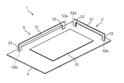
- FIG. 1 is a schematic diagram illustrating a schematic configuration of an antenna device according to Embodiment 1.
- FIG. It is a schematic diagram explaining schematic structure of the antenna apparatus in a comparative example. It is a figure explaining the antenna characteristic at the time of installing the antenna apparatus of a comparative example horizontally. It is a figure explaining the antenna characteristic at the time of installing the antenna apparatus of a comparative example vertically vertical. It is a figure explaining the antenna characteristic at the time of installing the antenna apparatus of a comparative example vertically perpendicularly. It is a figure explaining the antenna characteristic at the time of installing the antenna apparatus which concerns on Embodiment 1 in the horizontal direction. It is a figure explaining the antenna characteristic at the time of installing the antenna apparatus which concerns on Embodiment 1 in the vertical vertical direction.
- FIG. 6 is a schematic diagram illustrating a schematic configuration of an antenna device according to Embodiment 2.
- FIG. It is a figure explaining the antenna characteristic at the time of installing the antenna apparatus which concerns on Embodiment 2 in the horizontal direction. It is a figure explaining the antenna characteristic at the time of installing the antenna apparatus which concerns on Embodiment 2 in the vertical vertical direction. It is a figure explaining the antenna characteristic at the time of installing the antenna apparatus which concerns on Embodiment 2 in the vertical horizontal direction.
- Embodiments of the present invention will be listed and described. Moreover, you may combine arbitrarily at least one part of embodiment described below.
- An antenna device is an antenna device in which a plurality of antenna elements are mounted on one surface of a substrate, and each of the plurality of antenna elements is a rectangle disposed separately from one surface of the substrate.
- a flat plate portion and a connecting portion for connecting one end side in the longitudinal direction of the flat plate portion to the substrate, the longitudinal direction of the flat plate portion in one antenna element, and the flat plate portion in at least one other antenna element Each of the plurality of antenna elements is arranged along the peripheral edge of the substrate so as to intersect the longitudinal direction of the substrate.
- the radio wave transmitted from one antenna element has directivity
- the radio wave transmitted from the other antenna element does not have directivity
- other antenna elements By selectively using, transmission intensity does not decrease in a specific direction, and a decrease in reception sensitivity due to directivity can be suppressed. As a result, a situation in which communication is disabled can be avoided.
- each of the plurality of antenna elements includes a support portion that supports the other end side in the longitudinal direction of the flat plate portion.
- the stability of the antenna element can be improved.
- the antenna device can be installed in a place where vibration is likely to occur, such as a vehicle. Even when it is attached, radio waves can be transmitted and received stably.
- the flat plate portion, the connection portion, and the support portion in each antenna element are integrally formed.
- each antenna element is mounted on one surface of the substrate such that the side surface of the flat plate portion faces one surface of the substrate.
- mounting is performed so that the wide surface of the flat plate portion and the substrate surface are perpendicular to each other, so that bending processing for bending a part of the antenna element is not necessary, and the manufacturing process is simplified. be able to.
- the length in the longitudinal direction of the flat plate portion in the one antenna element is shorter than the length in the longitudinal direction of the flat plate portion in the other antenna element.
- the antenna characteristics of the two antenna elements can be made different by changing the antenna length between one antenna element and another antenna element.
- an antenna element having good antenna characteristics for example, the transmission strength does not decrease in a specific direction, and a decrease in reception sensitivity due to directivity can be suppressed.
- the one antenna element includes a dielectric member.
- the antenna characteristics can be improved by controlling the electrical length of the one antenna element.
- the dielectric member has a relative permittivity that gives a wavelength shortening effect to the one antenna element.
- the antenna characteristics can be improved by giving a wavelength shortening effect to the one antenna element and controlling the electrical length of the one antenna element.
- FIG. 1 is a schematic diagram illustrating a schematic configuration of the antenna device according to the first embodiment.
- the antenna device 1 according to Embodiment 1 transmits and receives radio waves when performing wireless communication between an in-vehicle control device mounted on a vehicle and a portable device carried by an occupant, for example, in a vehicle communication system. It is an antenna apparatus for.
- the antenna device 1 is built in, for example, an in-vehicle control device.
- the antenna device 1 built in the vehicle-mounted control device will be described, but the antenna device 1 may be built in a portable device.
- the antenna device 1 includes two antenna elements 2 and 3 mounted on one surface of the substrate 5.
- the substrate 5 is a rectangular printed board, and a signal processing circuit 51 including a transmission / reception circuit is mounted on the central portion of one surface thereof, and a layered ground conductor (not shown) is mounted on the other surface.
- the signal processing circuit 51 is connected to, for example, a vehicle-mounted control device via a connector not shown in the figure, and the vehicle-mounted control signal output from the vehicle-mounted control device and received via the antenna elements 2 and 3. Input / output control signals addressed to the control unit.
- the signal processing circuit 51 has a function of mutually converting a control signal input / output through the connector and a radio signal transmitted / received via the antenna elements 2 and 3.
- the antenna elements 2 and 3 included in the antenna device 1 are arranged along the periphery of the substrate 5.
- one antenna element 2 is disposed on the short side of the substrate 5, and the other antenna element 3 is disposed on the long side of the substrate 5.
- the antenna element 2 arranged on the short side of the substrate 5 is also referred to as the short side antenna element 2, and the long side of the substrate 5 is described.
- the antenna element 3 arranged on the side is also referred to as a long-side antenna element 3.
- the short-side antenna element 2 constitutes a monopole antenna, and has a rectangular flat plate portion 21 disposed away from one surface of the substrate 5 and one end side in the longitudinal direction of the flat plate portion 21 on the substrate 5.
- the connection part 22 to connect and the support part 23 which supports the other end side of the longitudinal direction of the flat plate part 21 are provided.
- the flat plate portion 21, the connection portion 22, and the support portion 23 are made of a metal such as brass (C2600), and are integrally formed of a plate material having a thickness of about 5 mm, for example.
- the flat plate portion 21 of the short-side antenna element 2 has an appropriate length in the longitudinal direction and a width of about 5 mm in the height direction.
- the side surface of the flat plate portion 21 (the lower surface of the flat plate portion 21 in the example of FIG. 1) is separated from one surface of the substrate 5 by about 10 mm to 15 mm.
- the flat plate portion 21 is mounted on one surface of the substrate 5 so that the longitudinal direction of the flat plate portion 21 is along the peripheral edge of the short side of the substrate 5. That is, in the present embodiment, the short-side antenna element 2 is mounted on one surface of the substrate 5 so that the wide surface of the flat plate portion 21 and one surface of the substrate 5 are substantially perpendicular.
- connection portion 22 of the short-side antenna element 2 is a rectangular flat plate member whose upper end is continuous with one end side of the flat plate portion 21, and one end side of the flat plate portion 21 is connected to the substrate 5.
- the height of the connecting portion 22 from one surface of the substrate 5 is about 10 mm to 15 mm.
- the lower end of the connecting portion 22 is attached to one surface of the substrate 5 such that the wide surface thereof is substantially perpendicular to the one surface of the substrate 5.
- the substrate 5 includes a connection side mounting portion 52a at an attachment site to which the connection portion 22 is attached.
- the connection side mounting part 52a includes, for example, an insertion hole into which the lower end of the connection part 22 is inserted, and a pattern wiring formed at the peripheral part of the insertion hole.
- the pattern wiring provided in the connection side mounting part 52 a is electrically connected to the signal processing circuit 51.
- the support portion 23 of the short-side antenna element 2 is a rectangular flat plate member whose upper end is connected to the other end side of the flat plate portion 21, and supports the other end side of the flat plate portion 21.
- the support part 23 has the same height as the connection part 22, and the height is about 10 mm to 15 mm from one surface of the substrate 5.
- the lower end of the support portion 23 is attached to one surface of the substrate 5 such that the wide surface thereof is substantially orthogonal to the one surface of the substrate 5.
- the substrate 5 includes an insulating-side mounting portion 52b at an attachment site to which the support portion 23 is attached.
- the insulating-side mounting part 52b includes, for example, an insertion hole into which the lower end of the support part 23 is inserted, and a pattern wiring formed at the peripheral part of the insertion hole.
- the pattern wiring provided in the insulating-side mounting part 52 b is electrically insulated from the signal processing circuit 51.
- the support part 23 it was set as the structure provided with the support part 23 in order to support the flat plate part 21 of the short side antenna element 2 stably, but since the flat plate part 21 can be stably supported by the connection part 22, it is. If it exists, the support part 23 does not necessarily need to be provided.
- the short side antenna element 2 was set as the structure provided with the support part 23, it is good also as a structure provided with the support part 23 as a different body. In this case, the support part 23 does not have to be the same metal plate material as the flat plate part 21 and the connection part 22, and may be formed of a square member having insulation properties such as a resin.
- the configuration of the long side antenna element 3 is the same as that of the short side antenna element 2. That is, the long-side antenna element 3 is a monopole antenna, and has a rectangular plate-like flat plate portion 31 arranged away from one surface of the substrate 5 and one end side in the longitudinal direction of the flat plate portion 31 on the substrate 5. And a support portion 33 that supports the other end side in the longitudinal direction of the flat plate portion 31.
- the flat plate portion 31, the connection portion 32, and the support portion 33 are made of a metal such as brass (C2600), and are integrally formed of a plate material having a thickness of about 5 mm, for example.
- the flat plate portion 31 of the long side antenna element 3 has an appropriate length in the longitudinal direction and a width of about 5 mm in the height direction.
- the side surface of the flat plate portion 31 (the lower surface of the flat plate portion 31 in the example of FIG. 1) is separated from one surface of the substrate 5 by about 10 mm to 15 mm and faces the one surface of the substrate 5.
- the flat plate portion 31 is mounted on one surface of the substrate 5 such that the longitudinal direction of the flat plate portion 31 extends along the peripheral edge of the long side of the substrate 5. That is, in the present embodiment, the long-side antenna element 3 is mounted on one surface of the substrate 5 such that the wide surface of the flat plate portion 31 and one surface of the substrate 5 are substantially perpendicular.
- connection portion 32 of the long-side antenna element 3 is a rectangular flat plate member whose upper end is continuous with one end side of the flat plate portion 31, and one end side of the flat plate portion 31 is connected to the substrate 5.
- the height of the connecting portion 32 from one surface of the substrate 5 is about 10 mm to 15 mm.
- the lower end of the connection portion 32 is attached to one surface of the substrate 5 such that the wide surface thereof is substantially perpendicular to the one surface of the substrate 5.
- the substrate 5 includes a connection side mounting portion 53a at an attachment site to which the connection portion 32 is attached.
- connection side mounting portion 53a is provided, for example, in the vicinity of the connection side mounting portion 52a on which the short side antenna element 2 is mounted, and an insertion hole into which the lower end of the connection portion 32 is inserted and a peripheral portion of the insertion hole. Pattern wiring to be formed.
- the pattern wiring included in the connection side mounting portion 53 a is electrically connected to the signal processing circuit 51.
- the support part 33 of the long-side antenna element 3 is a rectangular flat plate member whose upper end is connected to the other end side of the flat plate part 31, and supports the other end side of the flat plate part 31.
- the support portion 33 has the same height as the connection portion 32, and the height is about 10 mm to 15 mm from one surface of the substrate 5.
- the lower end of the support portion 33 is attached to one surface of the substrate 5 such that the wide surface thereof is substantially orthogonal to the one surface of the substrate 5.
- the substrate 5 includes an insulating-side mounting portion 53b at an attachment site to which the support portion 33 is attached.
- the insulating side mounting portion 53b includes, for example, an insertion hole into which the lower end of the support portion 33 is inserted, and a pattern wiring formed at the peripheral edge of the insertion hole.
- the pattern wiring provided in the insulating side mounting portion 53 b is electrically insulated from the signal processing circuit 51.
- the support portion 33 is provided to stably support the flat plate portion 31 of the long side antenna element 3, but the flat plate portion 31 can be stably supported by the connection portion 32. If it exists, the support part 33 does not necessarily need to be provided. Further, in the present embodiment, the long-side antenna element 3 is configured to include the support portion 33, but may be configured to include the support portion 33 as a separate body. In this case, the support part 33 does not need to be the same metal plate material as the flat plate part 31 and the connection part 32, and may be formed of a square member having insulation properties such as a resin.
- the lengths of the flat plate portions 21 and 31 in the antenna elements 2 and 3 are appropriately designed according to the wavelength of the radio wave transmitted and received through the antenna elements 2 and 3.
- an antenna device including a single antenna element having a shape bent along the periphery of the substrate, and the characteristics of the antenna device Will be described.
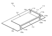
- FIG. 2 is a schematic diagram illustrating a schematic configuration of an antenna device in a comparative example.
- the antenna device 100 of the comparative example includes an antenna element 110 mounted on one surface of a substrate 150.
- the board 150 is a rectangular printed board.
- a signal processing circuit 151 including a transmission / reception circuit is mounted on the center of one surface thereof, and a layered ground conductor (not shown) is mounted on the other surface.
- the antenna element 110 included in the antenna device 100 is disposed along the periphery of the substrate 150.
- the antenna element 110 constitutes a monopole antenna and has rectangular flat plate portions 111 and 112 that are spaced apart from the substrate 150 and a connecting portion that connects one end of the flat plate portion 111 in the longitudinal direction to the substrate 150. 113, and the other end of the flat plate portion 111 and support portions 114a to 114c for supporting both ends of the flat plate portion 112, respectively.
- the flat plate portions 111 and 112, the connection portion 113, and the support portions 114a to 114c are made of metal such as brass, and are integrally formed by bending a plate material having a thickness of, for example, about 5 mm.
- the two flat plate portions 111 and 112 included in the antenna element 110 are connected so as to be orthogonal to each other, one flat plate portion (the flat plate portion 111) is disposed along the short side of the substrate 150, and the other flat plate portion (the flat plate portion 112). Are arranged along the long side of the substrate 150.
- the two flat plate portions 111 and 112 are arranged so that the respective wide surfaces face one surface of the substrate 150.
- connection unit 113 connects one end of the flat plate unit 111 to the substrate 150.
- a connection side mounting portion 152 is provided at a mounting portion between the connection portion 113 and the substrate 150 of the antenna element 110.
- the connection side mounting part 152 includes, for example, an insertion hole into which the lower end of the connection part 113 is inserted, and a pattern wiring formed at the peripheral edge of the insertion hole.
- the pattern wiring included in the connection side mounting unit 152 is electrically connected to the signal processing circuit 151.
- the support portion 114 a supports the other end of the flat plate portion 111.
- the support portions 114b and 114c support one end and the other end of the flat plate portion 112, respectively.
- Insulation side mounting portions 153a to 153c are provided at mounting portions of the support portions 114a to 114c and the substrate 150, respectively.
- the insulating-side mounting portions 153a to 153c include, for example, an insertion hole into which the lower ends of the support portions 114a to 114c are inserted, and a pattern wiring formed at the peripheral portion of the insertion hole.
- the pattern wirings provided in the insulating-side mounting portions 153a to 153c are electrically insulated from the signal processing circuit 151.
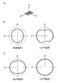
- FIG. 3 is a diagram for explaining antenna characteristics when the antenna device 100 of the comparative example is installed horizontally.
- FIG. 3A schematically shows the direction in which the antenna device 100 is installed.
- a state in which the substrate 150 of the antenna device 100 is installed in a horizontal direction more specifically, a state in which the long side of the substrate 150 is installed in the x-axis direction and the short side in the y-axis direction is shown.
- FIG. 3B shows the directivity (simulation result) of the radio wave transmitted from the antenna device 100 in a state where the substrate 150 of the antenna device 100 is installed horizontally.
- the electric field intensity of the radio wave transmitted from the antenna device 100 is isotropic in the horizontal plane (in the xy plane) in both vertical polarization and horizontal polarization. It can be seen that a characteristic close to omnidirectional characteristics can be obtained.
- FIG. 4 is a diagram for explaining antenna characteristics when the antenna device 100 of the comparative example is installed in the vertical vertical direction.
- FIG. 4A schematically shows the direction in which the antenna device 100 is installed.
- FIG. 4B shows the directivity (simulation result) of the radio wave transmitted from the antenna device 100 in a state where the substrate 150 of the antenna device 100 is installed in the vertical vertical direction.
- the electric field intensity of the radio wave transmitted from the antenna device 100 has directivity in the horizontal plane (in the xy plane). It shows that the electric field strength decreases in the 25-degree direction and the 205-degree direction with respect to the x-axis, and the horizontal electric field strength decreases in the 110-degree direction and the 290-degree direction with respect to the x-axis.
- FIG. 5 is a diagram for explaining the antenna characteristics when the antenna device 100 of the comparative example is installed in the vertical horizontal direction.
- FIG. 5A schematically shows the direction in which the antenna device 100 is installed.
- FIG. 5B shows the directivity (simulation result) of the radio wave transmitted from the antenna device 100 in a state where the substrate 150 of the antenna device 100 is installed in the horizontal direction.
- the electric field intensity of the radio wave transmitted from the antenna device 100 is isotropic in the horizontal plane (in the xy plane) in both the vertical polarization and the horizontal polarization. It can be seen that a characteristic close to omnidirectional characteristics can be obtained.
- the transmitting side (the in-vehicle control device or the portable device) Transmission strength of radio waves transmitted from the mobile phone) and reception strength of radio waves received at the receiving side (mobile device or in-vehicle control device) decrease in a specific direction, so that sufficient receiving strength cannot be obtained at the receiving side. There is a possibility that communication will be disabled.
- the antenna device 1 according to Embodiment 1 includes the short-side antenna element 2 and the long-side antenna element 3, and both the short-side antenna element 2 and the long-side antenna element 3 are used. By sending and receiving radio waves, avoid situations where communication is impossible.
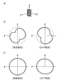
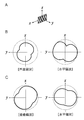
- FIG. 6 is a diagram for explaining antenna characteristics when the antenna device 1 according to Embodiment 1 is installed horizontally.
- FIG. 6A schematically shows the direction in which the antenna device 1 is installed.
- FIG. 6B shows the directivity (simulation result) of the radio wave transmitted from the long-side antenna element 3 in a state where the substrate 5 of the antenna device 1 is installed horizontally.
- FIG. 6C shows the directivity (simulation result) of the radio wave transmitted from the short-side antenna element 2 in a state where the substrate 5 of the antenna device 1 is installed horizontally.
- the electric field intensity of the radio wave transmitted from the short-side antenna element 2 is isotropic with respect to the vertical polarization, but within the horizontal plane with respect to the horizontal polarization. It has directivity (in the xy plane), and shows that the electric field strength decreases in the direction of 165 degrees and 355 degrees with respect to the x-axis.
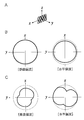
- FIG. 7 is a diagram for explaining antenna characteristics when the antenna device 1 according to the first embodiment is installed in a vertical vertical direction.
- FIG. 7A schematically shows the direction in which the antenna device 1 is installed. In this example, the state where the substrate 5 of the antenna device 1 is installed in the vertical vertical direction, more specifically, the state where the long side of the substrate 5 is installed in the z-axis direction and the short side in the y-axis direction. Show.
- FIG. 7B shows the directivity (simulation result) of the radio wave transmitted from the long-side antenna element 3 in a state where the substrate 5 of the antenna device 1 is installed vertically vertically.
- FIG. 7C shows the directivity (simulation result) of the radio wave transmitted from the short-side antenna element 2 in a state where the substrate 5 of the antenna device 1 is installed vertically vertically.
- the electric field intensity of the radio wave transmitted from the short-side antenna element 2 is in the horizontal plane (in the xy plane) in both the vertical polarization and the horizontal polarization. It is understood that characteristics that are isotropic and close to omnidirectional characteristics can be obtained.
- FIG. 8 is a diagram for explaining the antenna characteristics when the antenna device 1 according to the first embodiment is installed vertically and horizontally.
- FIG. 8A schematically shows the direction in which the antenna device 1 is installed. In this example, a state in which the substrate 5 of the antenna device 1 is installed in the vertical horizontal direction, more specifically, a state in which the long side of the substrate 5 is installed in the x-axis direction and the short side in the z-axis direction is shown.
- FIG. 8B shows the directivity (simulation result) of the radio wave transmitted from the long-side antenna element 3 in a state where the substrate 5 of the antenna device 1 is installed in the vertical horizontal direction.
- FIG. 8C shows the directivity (simulation result) of the radio wave transmitted from the short-side antenna element 2 in a state where the substrate 5 of the antenna device 1 is installed in the vertical horizontal direction.
- the electric field strength of the radio wave transmitted from the short-side antenna element 2 has directivity in the horizontal plane (in the xy plane), and the vertical polarization Indicates that the electric field strength decreases in the direction of 110 degrees and 290 degrees with respect to the x axis, and the horizontal polarization indicates that the electric field strength decreases in the directions of 15 degrees and 195 degrees with respect to the x axis. Yes.
- the antenna device 1 according to Embodiment 1 even when the radio wave transmitted from the short-side antenna element 2 has directivity (when the substrate 5 is installed horizontally, In the case of being installed vertically and horizontally), the radio wave transmitted from the long-side antenna element 3 has characteristics close to omnidirectionality. Even if the radio wave transmitted from the long-side antenna element 3 has directivity (when the substrate 5 is installed in the vertical vertical direction), the radio wave transmitted from the short-side antenna element 2 is A characteristic close to omnidirectionality is obtained. Therefore, the antenna device 1 according to Embodiment 1 has the short-side antenna element 2 and the long-side antenna element 3 on the transmitting side and the receiving side regardless of the orientation of the substrate 5. By selectively using, transmission intensity does not decrease in a specific direction, and a decrease in reception sensitivity due to directivity can be suppressed. As a result, a situation in which communication is disabled can be avoided.
- FIG. 9 is a schematic diagram illustrating a schematic configuration of the antenna device 1 according to the second embodiment.
- the antenna device 1 according to the second embodiment includes a short-side antenna element 2 and a long-side antenna element 3 mounted on one surface of the substrate 5, and a dielectric member 7 provided for the short-side antenna element 2. Is provided.
- the configurations of the short-side antenna element 2 and the long-side antenna element 3 are the same as those in the first embodiment, and the description thereof is omitted.
- the dielectric member 7 is a rectangular parallelepiped housing formed of a dielectric, for example, and houses the short-side antenna element 2 therein.
- the dielectric constituting the dielectric member 7 has a relative permittivity that gives a wavelength shortening effect to the short-side antenna element 2.
- the dielectric constant of this dielectric is 28, for example.
- the dielectric member 7 sandwiches the flat plate portion 21 of the short-side antenna element 2 and has two dielectric substrates 71 and 72 disposed opposite to the one surface and the other surface of the flat plate portion 21, respectively, and the flat plate portion.
- the dielectric substrate 73 is disposed opposite to the side surface of the connecting portion 22 at one end side in the longitudinal direction of 21, and the dielectric substrate 74 is disposed opposite to the side surface of the support portion 23 in the other end side in the longitudinal direction of the flat plate portion 21. And a dielectric substrate 75 covering the upper side of the short-side antenna element 2.
- FIG. 10 is a diagram for explaining antenna characteristics when the antenna device 1 according to Embodiment 2 is installed horizontally.
- FIG. 10A schematically shows the direction in which the antenna device 1 is installed.
- FIG. 10B shows the directivity (simulation result) of a radio wave transmitted from the short-side antenna element 2 that does not include the dielectric member 7 for comparison.
- the electric field intensity of the radio wave transmitted from the short-side antenna element 2 is isotropic with respect to the vertical polarization as described in the first embodiment, but the horizontal polarization is
- the wave has directivity in the horizontal plane (in the xy plane), and shows that the electric field strength decreases in the 165 degree direction and the 355 degree direction with respect to the x axis.
- FIG. 10C shows the directivity (simulation result) of the radio wave transmitted from the short-side antenna element 2 including the dielectric member 7.
- the directivity of horizontal polarization is improved, and the radio wave transmitted from the short-side antenna element has a characteristic close to omnidirectionality. It can also be seen that the radio wave intensity is also high.
- FIG. 11 is a diagram for explaining the antenna characteristics when the antenna device 1 according to the second embodiment is installed vertically.
- FIG. 11A schematically shows the direction in which the antenna device 1 is installed. In this example, the state where the substrate 5 of the antenna device 1 is installed in the vertical vertical direction, more specifically, the state where the long side of the substrate 5 is installed in the z-axis direction and the short side in the y-axis direction. Show.
- FIG. 11B shows the directivity (simulation result) of a radio wave transmitted from the short-side antenna element 2 that does not include the dielectric member 7 for comparison.
- FIG. 11C shows the directivity (simulation result) of the radio wave transmitted from the short-side antenna element 2 including the dielectric member 7. Even when the dielectric member 7 is provided, the electric field intensity of the radio wave transmitted from the short-side antenna element 2 is isotropic, and a characteristic close to omnidirectionality can be obtained.
- FIG. 12 is a diagram for explaining the antenna characteristics when the antenna device 1 according to the second embodiment is installed in the vertical horizontal direction.
- FIG. 12A schematically shows the direction in which the antenna device 1 is installed. In this example, a state in which the substrate 5 of the antenna device 1 is installed in the vertical horizontal direction, more specifically, a state in which the long side of the substrate 5 is installed in the x-axis direction and the short side in the z-axis direction is shown. ing.
- FIG. 12B shows the directivity (simulation result) of a radio wave transmitted from the short-side antenna element 2 that does not include the dielectric member 7 for comparison.
- the electric field intensity of the radio wave transmitted from the short-side antenna element 2 has directivity in the horizontal plane (in the xy plane).
- the electric field strength decreases in the direction of 110 degrees and 290 degrees with respect to the x axis
- the electric field strength decreases in the directions of 15 degrees and 195 degrees with respect to the x axis. It shows that.
- FIG. 12C shows the directivity (simulation result) of the radio wave transmitted from the short-side antenna element 2 including the dielectric member 7.
- the directivity is improved in both vertical polarization and horizontal polarization.
- the dielectric member 7 for the short-side antenna element 2 by providing the dielectric member 7 for the short-side antenna element 2, the directivity of the radio wave transmitted from the short-side antenna element 2 can be improved. As a result, it is possible to prevent a decrease in reception sensitivity due to the situation, and thus avoid situations where communication is impossible.
- each of the short side antenna element 2 and the long side antenna element 3 is provided, but either one of the short side antenna element 2 and the long side antenna element 3 is used.
- the structure provided with two or more of one or both may be sufficient.
Landscapes
- Engineering & Computer Science (AREA)
- Computer Networks & Wireless Communication (AREA)
- Signal Processing (AREA)
- Remote Sensing (AREA)
- Computer Security & Cryptography (AREA)
- Radar, Positioning & Navigation (AREA)
- Variable-Direction Aerials And Aerial Arrays (AREA)
- Details Of Aerials (AREA)
Abstract
アンテナ装置の提供。 基板の一面に複数のアンテナ要素を実装してあるアンテナ装置であって、複数のアンテナ要素の夫々は、基板の一面から離隔して配置される矩形平板状の平板部と、平板部の長手方向の一端側を前記基板に接続する接続部とを備え、一のアンテナ要素における平板部の長手方向と、少なくとも1つの他のアンテナ要素における平板部の長手方向とが交差するように、複数のアンテナ要素の夫々を基板の周縁に沿って配置してある。
Description
本発明は、アンテナ装置に関する。
本出願は、2016年12月1日出願の日本出願第2016-234272号に基づく優先権を主張し、前記日本出願に記載された全ての記載内容を援用するものである。
本出願は、2016年12月1日出願の日本出願第2016-234272号に基づく優先権を主張し、前記日本出願に記載された全ての記載内容を援用するものである。
従来、キーレスエントリーシステム又はスマートエントリー(登録商標)システム等に用いられる車両用通信システムが提案されている。このような車両用通信システムでは、乗員が所持する携帯機と、車両ドアの施錠及び解錠を制御する車載制御装置とが無線通信することによって、車両ドアの施錠及び解錠を行う。
携帯機及び車載制御装置は、電波を用いて無線通信するためのアンテナ装置をそれぞれ備える。例えば、特許文献1には、携帯機又は車載制御装置で用いられるアンテナ装置の1つとして、矩形状の回路基板と、回路基板から離隔して配置され、回路基板の外周縁に沿って屈曲した平板状のアンテナ要素とを備えるアンテナ装置が開示されている。
しかしながら、特許文献1に開示されたアンテナ装置では、特定の方向で電波の受信感度が低下する現象が発生している。このため、車両に設置されたアンテナ装置の基板の向きと、乗員が操作する携帯機に設けられたアンテナ装置の基板の向きとの間の相対的な位置関係によっては、両者の間で受信感度が大きく低下し、通信不能となる状況が起こり得る。
本発明は、斯かる事情に鑑みてなされたものであり、任意の向きでアンテナ装置の基板が設置された場合であっても、通信不能となる状況を回避することができるアンテナ装置を提供することを目的とする。
本願の一態様に係るアンテナ装置は、基板の一面に複数のアンテナ要素を実装してあるアンテナ装置であって、前記複数のアンテナ要素の夫々は、前記基板の一面から離隔して配置される矩形平板状の平板部と、該平板部の長手方向の一端側を前記基板に接続する接続部とを備え、一のアンテナ要素における平板部の長手方向と、少なくとも1つの他のアンテナ要素における平板部の長手方向とが交差するように、前記複数のアンテナ要素の夫々を前記基板の周縁に沿って配置してある。
本願によれば、任意の向きでアンテナ装置の基板が設置された場合であっても、通信不能となる状況を回避することができる。
本発明の実施態様を列記して説明する。また、以下に記載する実施形態の少なくとも一部を任意に組み合わせてもよい。
本願の一態様に係るアンテナ装置は、基板の一面に複数のアンテナ要素を実装してあるアンテナ装置であって、前記複数のアンテナ要素の夫々は、前記基板の一面から離隔して配置される矩形平板状の平板部と、該平板部の長手方向の一端側を前記基板に接続する接続部とを備え、一のアンテナ要素における平板部の長手方向と、少なくとも1つの他のアンテナ要素における平板部の長手方向とが交差するように、前記複数のアンテナ要素の夫々を前記基板の周縁に沿って配置してある。
上記一態様にあっては、一のアンテナ要素から送信される電波に指向性が存在する場合であっても、他のアンテナ要素から送信される電波に指向性が存在しない場合、他のアンテナ要素を選択的に使用することにより、特定の方向で送信強度が低下することがなくなり、指向性に起因した受信感度の低下を抑制することができる。この結果、通信不能となる状況を回避することができる。
本願の一態様に係るアンテナ装置は、前記複数のアンテナ要素の夫々は、前記平板部の長手方向の他端側を支持する支持部を備える。
上記一態様にあっては、平板部の長手方向の他端側を支持部により支持するので、アンテナ要素の安定性を高めることができ、例えば車両などの振動が発生し易い場所にアンテナ装置が取り付けられている場合であっても、安定して電波を送受信することができる。
本願の一態様に係るアンテナ装置は、各アンテナ要素における前記平板部と、前記接続部と、前記支持部とを一体に形成してある。
上記一態様にあっては、各アンテナ要素の平板部、接続部、及び支持部を一体に形成するので、製造工程を簡略化し、製造コストを削減することができる。
本願の一態様に係るアンテナ装置は、前記平板部の側面と前記基板の一面とが対向するように、各アンテナ要素を前記基板の一面に実装してある。
上記一態様にあっては、前記平板部の幅広面と基板面とが垂直となるように実装されるので、アンテナ要素の一部を折り曲げる折曲加工等が不要となり、製造工程を簡略化することができる。
本願の一態様に係るアンテナ装置は、前記一のアンテナ要素における平板部の長手方向の長さを、前記他のアンテナ要素における平板部の長手方向の長さより短くしてある。
上記一態様にあっては、一のアンテナ要素と他のアンテナ要素との間でアンテナ長を異ならせることにより、両者のアンテナ特性を異ならせることができる。また、アンテナ特性が良好なアンテナ要素を選択的に使用することにより、例えば、特定の方向で送信強度が低下することがなくなり、指向性に起因した受信感度の低下を抑制することができる。
本願の一態様に係るアンテナ装置は、前記一のアンテナ要素は、誘電体部材を備える。
上記一態様にあっては、前記一のアンテナ要素における電気長を制御することにより、アンテナ特性を改善することができる。
本願の一態様に係るアンテナ装置は、前記誘電体部材は、前記一のアンテナ要素に対して波長短縮効果を与える比誘電率を有する。
上記一態様にあっては、前記一のアンテナ要素に対して波長短縮効果を与え、前記一のアンテナ要素における電気長を制御することにより、アンテナ特性を改善することができる。
以下、本発明をその実施の形態を示す図面に基づいて具体的に説明する。
(実施の形態1)
図1は実施の形態1に係るアンテナ装置の概略構成を説明する模式図である。実施の形態1に係るアンテナ装置1は、例えば車両用通信システムにおいて、車両に搭載される車載制御装置と、乗員によって携帯される携帯機との間で無線通信を行う際に、電波を送受信するためのアンテナ装置である。アンテナ装置1は、例えば車載制御装置に内蔵される。以下では、車載制御装置に内蔵されるアンテナ装置1について説明を行うが、アンテナ装置1は携帯機に内蔵されるものであってもよい。
(実施の形態1)
図1は実施の形態1に係るアンテナ装置の概略構成を説明する模式図である。実施の形態1に係るアンテナ装置1は、例えば車両用通信システムにおいて、車両に搭載される車載制御装置と、乗員によって携帯される携帯機との間で無線通信を行う際に、電波を送受信するためのアンテナ装置である。アンテナ装置1は、例えば車載制御装置に内蔵される。以下では、車載制御装置に内蔵されるアンテナ装置1について説明を行うが、アンテナ装置1は携帯機に内蔵されるものであってもよい。
アンテナ装置1は、基板5の一面に実装された2つのアンテナ要素2,3を備える。基板5は、矩形状のプリント基板であり、その一面の中央部には送受信用回路を含む信号処理回路51が実装され、他面には図に示していない層状の接地導体が実装される。信号処理回路51は、図に示していないコネクタを介して、例えば車載制御装置に接続されており、車載制御装置から出力される携帯機宛の制御信号、及びアンテナ要素2,3を通じて受信した車載制御装置宛の制御信号を入出力する。信号処理回路51は、コネクタを通じて入出力する制御信号と、アンテナ要素2,3を介して送受信する無線信号とを相互に変換する機能を備える。
アンテナ装置1が備えるアンテナ要素2,3は、基板5の周縁に沿って配置される。図1の例では、一方のアンテナ要素2は、基板5の短辺側に配置され、他方のアンテナ要素3は、基板5の長辺側に配置されている。以下の説明において、アンテナ要素2,3のそれぞれを区別して説明する場合、基板5の短辺側に配置されているアンテナ要素2を短辺側アンテナ要素2とも記載し、基板5の長辺側に配置されているアンテナ要素3を長辺側アンテナ要素3とも記載する。
短辺側アンテナ要素2は、モノポール型のアンテナを構成し、基板5の一面から離隔して配置される矩形平板状の平板部21と、平板部21の長手方向の一端側を基板5に接続する接続部22と、平板部21の長手方向の他端側を支持する支持部23とを備える。平板部21、接続部22、及び支持部23は、黄銅(C2600)などの金属からなり、例えば5mm程度の厚みを有する板材により一体的に形成されている。
短辺側アンテナ要素2の平板部21は、長手方向に適宜の長さを有し、高さ方向に5mm程度の幅を有する。本実施の形態に係る短辺側アンテナ要素は、平板部21の側面(図1の例では平板部21の下面)が基板5の一面から10mm~15mm程度離隔して基板5の一面に対向し、平板部21の長手方向が基板5の短辺側の周縁に沿うように基板5の一面に実装されている。すなわち、本実施の形態では、平板部21の幅広面と基板5の一面とが実質的に垂直となる向きにて、短辺側アンテナ要素2が基板5の一面に実装されている。
短辺側アンテナ要素2の接続部22は、その上端が平板部21の一端側に連なる矩形平板状の部材であり、平板部21の一端側を基板5に接続する。接続部22の基板5の一面からの高さは10mm~15mm程度である。接続部22の下端は、その幅広面が基板5の一面と略直交する向きにて、基板5の一面に取り付けられる。基板5は、接続部22が取り付けられる取付部位に接続側実装部52aを備える。接続側実装部52aは、例えば、接続部22の下端が挿入される挿入孔と、挿入孔の周縁部に形成されるパターン配線とを備える。接続側実装部52aが備えるパターン配線は、信号処理回路51に電気的に接続されている。
短辺側アンテナ要素2の支持部23は、その上端が平板部21の他端側に連なる矩形平板状の部材であり、平板部21の他端側を支持する。支持部23は接続部22と同じ高さを有し、その高さは基板5の一面から10mm~15mm程度である。支持部23の下端は、その幅広面が基板5の一面と略直交する向きにて、基板5の一面に取り付けられる。基板5は、支持部23が取り付けられる取付部位に絶縁側実装部52bを備える。絶縁側実装部52bは、例えば、支持部23の下端が挿入される挿入孔と、挿入孔の周縁部に形成されるパターン配線とを備える。絶縁側実装部52bが備えるパターン配線は、信号処理回路51に対して電気的に絶縁される。
なお、本実施の形態では、短辺側アンテナ要素2の平板部21を安定的に支持するために支持部23を備える構成としたが、接続部22により平板部21を安定的に支持できるのであれば、支持部23は必ずしも備えていなくてもよい。
また、本実施の形態では、短辺側アンテナ要素2が支持部23を備える構成としたが、支持部23を別体として備える構成としてもよい。この場合、支持部23は、平板部21や接続部22と同じ金属製の板材である必要はなく、樹脂等の絶縁性を有する角材などにより形成されていてもよい。
また、本実施の形態では、短辺側アンテナ要素2が支持部23を備える構成としたが、支持部23を別体として備える構成としてもよい。この場合、支持部23は、平板部21や接続部22と同じ金属製の板材である必要はなく、樹脂等の絶縁性を有する角材などにより形成されていてもよい。
長辺側アンテナ要素3の構成は、短辺側アンテナ要素2と同様である。すなわち、長辺側アンテナ要素3は、モノポール型のアンテナであり、基板5の一面から離隔して配置される矩形平板状の平板部31と、平板部31の長手方向の一端側を基板5に接続する接続部32と、平板部31の長手方向の他端側を支持する支持部33とを備える。平板部31、接続部32、及び支持部33は、黄銅(C2600)などの金属からなり、例えば5mm程度の厚みを有する板材により一体的に形成されている。
長辺側アンテナ要素3の平板部31は、長手方向に適宜の長さを有し、高さ方向に5mm程度の幅を有する。本実施の形態に係る長辺側アンテナ要素3は、平板部31の側面(図1の例では平板部31の下面)が基板5の一面から10mm~15mm程度離隔して基板5の一面に対向し、平板部31の長手方向が基板5の長辺側の周縁に沿うように基板5の一面に実装されている。すなわち、本実施の形態では、平板部31の幅広面と基板5の一面とが実質的に垂直となる向きにて、長辺側アンテナ要素3が基板5の一面に実装されている。
長辺側アンテナ要素3の接続部32は、その上端が平板部31の一端側に連なる矩形平板状の部材であり、平板部31の一端側を基板5に接続する。接続部32の基板5の一面からの高さは10mm~15mm程度である。接続部32の下端は、その幅広面が基板5の一面と略直交する向きにて、基板5の一面に取り付けられる。基板5は、接続部32が取り付けられる取付部位に接続側実装部53aを備える。接続側実装部53aは、例えば、短辺側アンテナ要素2が実装される接続側実装部52aに近接して設けられ、接続部32の下端が挿入される挿入孔と、挿入孔の周縁部に形成されるパターン配線とを備える。接続側実装部53aが備えるパターン配線は、信号処理回路51に電気的に接続されている。
長辺側アンテナ要素3の支持部33は、その上端が平板部31の他端側に連なる矩形平板状の部材であり、平板部31の他端側を支持する。支持部33は接続部32と同じ高さを有し、その高さは基板5の一面から10mm~15mm程度である。支持部33の下端は、その幅広面が基板5の一面と略直交する向きにて、基板5の一面に取り付けられる。基板5は、支持部33が取り付けられる取付部位に絶縁側実装部53bを備える。絶縁側実装部53bは、例えば、支持部33の下端が挿入される挿入孔と、挿入孔の周縁部に形成されるパターン配線とを備える。絶縁側実装部53bが備えるパターン配線は、信号処理回路51に対して電気的に絶縁される。
なお、本実施の形態では、長辺側アンテナ要素3の平板部31を安定的に支持するために支持部33を備える構成としたが、接続部32により平板部31を安定的に支持できるのであれば、支持部33は必ずしも備えていなくてもよい。
また、本実施の形態では、長辺側アンテナ要素3が支持部33を備える構成としたが、支持部33を別体として備える構成としてもよい。この場合、支持部33は、平板部31や接続部32と同じ金属製の板材である必要はなく、樹脂等の絶縁性を有する角材などにより形成されていてもよい。
また、本実施の形態では、長辺側アンテナ要素3が支持部33を備える構成としたが、支持部33を別体として備える構成としてもよい。この場合、支持部33は、平板部31や接続部32と同じ金属製の板材である必要はなく、樹脂等の絶縁性を有する角材などにより形成されていてもよい。
ここで、各アンテナ要素2,3における平板部21,31の長さは、アンテナ要素2,3を介して送受信する電波の波長に応じて適宜設計される。例えば、車両用通信システムで用いられる300MHz帯の電波を送受信する場合、短辺側アンテナ要素2の長手方向の長さL1、及び長辺側アンテナ要素3の長手方向の長さL2の合計(=L1+L2)が15~24cm程度となり、L2がL1の1.5~1.7倍程度となるように設計される。
以下、実施の形態1に係るアンテナ装置1の特性を示す前に、比較例として、基板の周縁に沿って屈曲した形状を有する単一のアンテナ要素を備えたアンテナ装置、及び当該アンテナ装置の特性について説明する。
図2は比較例におけるアンテナ装置の概略構成を説明する模式図である。比較例のアンテナ装置100は、基板150の一面に実装されたアンテナ要素110を備える。基板150は、矩形状のプリント基板であり、その一面の中央部には送受信用回路を含む信号処理回路151が実装され、他面には図に示していない層状の接地導体が実装される。
アンテナ装置100が備えるアンテナ要素110は、基板150の周縁に沿って配置されている。アンテナ要素110は、モノポール型のアンテナを構成し、基板150から離隔して配置される矩形平板状の平板部111,112と、平板部111の長手方向の一端を基板150に接続する接続部113と、平板部111の他端、平板部112の両端をそれぞれ支持する支持部114a~114cとを備える。平板部111,112、接続部113、及び支持部114a~114cは、黄銅などの金属からなり、例えば5mm程度の厚みを有する板材を折り曲げ加工して一体に形成される。
アンテナ要素110が備える2つの平板部111,112は互いに直交するように連なり、一方の平板部(平板部111)は基板150の短辺に沿って配置され、他方の平板部(平板部112)は基板150の長辺に沿って配置される。なお、比較例においては、2つの平板部111,112は、それぞれの幅広面が基板150の一面に対向するように配置されている。
接続部113は、平板部111の一端を基板150に接続する。アンテナ要素110の接続部113と基板150との実装部位には、接続側実装部152が設けられている。接続側実装部152は、例えば、接続部113の下端が挿入される挿入孔と、挿入孔の周縁部に形成されるパターン配線とを備える。接続側実装部152が備えるパターン配線は、信号処理回路151に電気的に接続されている。
支持部114aは、平板部111の他端を支持する。また、支持部114b,114cは、平板部112の一端及び他端をそれぞれ支持する。支持部114a~114cと基板150との実装部位には、それぞれ絶縁側実装部153a~153cが設けられている。絶縁側実装部153a~153cは、例えば、支持部114a~114cの下端が挿入される挿入孔と、挿入孔の周縁部に形成されるパターン配線とを備える。絶縁側実装部153a~153cが備えるパターン配線は、信号処理回路151に対して電気的に絶縁される。
図3は比較例のアンテナ装置100を水平向きに設置した場合のアンテナ特性を説明する図である。図3Aは、アンテナ装置100が設置されている向きを模式的に示している。この例では、アンテナ装置100の基板150が水平向きに設置された状態、より詳細には、基板150の長辺がx軸方向、短辺がy軸方向を向くように設置された状態を示している。図3Bは、アンテナ装置100の基板150が水平向きに設置された状態において、アンテナ装置100から送信された電波の指向性(シミュレーション結果)を示している。アンテナ装置100の基板150が水平向きに設置された場合、アンテナ装置100から送信される電波の電界強度は、垂直偏波及び水平偏波の双方において、水平面内(xy平面内)で等方的であり、無指向性に近い特性が得られることが分かる。
図4は比較例のアンテナ装置100を鉛直縦向きに設置した場合のアンテナ特性を説明する図である。図4Aは、アンテナ装置100が設置されている向きを模式的に示している。この例では、アンテナ装置100の基板150が鉛直縦向きに設置された状態、より詳細には、基板150の長辺がz軸方向、短辺がy軸方向を向くように設置された状態を示している。図4Bは、アンテナ装置100の基板150が鉛直縦向きに設置された状態において、アンテナ装置100から送信された電波の指向性(シミュレーション結果)を示している。アンテナ装置100の基板150が鉛直縦向きに設置された場合、アンテナ装置100から送信される電波の電界強度は、水平面内(xy平面内)で指向性を有しており、垂直偏波についてはx軸に対して25度方向及び205度方向で電界強度が低下し、水平偏波についてはx軸に対して110度方向及び290度方向で電界強度が低下していることを示している。
図5は比較例のアンテナ装置100を鉛直横向きに設置した場合のアンテナ特性を説明する図である。図5Aは、アンテナ装置100が設置されている向きを模式的に示している。この例では、アンテナ装置100の基板150が鉛直横向きに設置された状態、より詳細には、基板150の長辺がx軸方向、短辺がz軸方向を向くように設置された状態を示している。図5Bは、アンテナ装置100の基板150が鉛直横向きに設置された状態において、アンテナ装置100から送信された電波の指向性(シミュレーション結果)を示している。アンテナ装置100の基板150が鉛直横向きに設置された場合、アンテナ装置100から送信される電波の電界強度は、垂直偏波及び水平偏波の双方において、水平面内(xy平面内)で等方的であり、無指向性に近い特性が得られることが分かる。
以上により、比較例のアンテナ装置100においては、例えば、車載制御装置内で基板150が水平向きに設置されており、携帯機が水平状態で携帯されている場合、送信側(車載制御装置又は携帯機)から送信される電波の送信強度、及び受信側(携帯機又は車載制御装置)で受信する電波の受信強度は特定の方向で低下するので、受信側にて十分な受信強度が得られず、通信不能となる可能性がある。
これに対し、実施の形態1に係るアンテナ装置1は、短辺側アンテナ要素2及び長辺側アンテナ要素3を備えており、短辺側アンテナ要素2及び長辺側アンテナ要素3の双方にて電波を送受信することにより、通信不能となる状況を回避する。
以下、実施の形態1に係るアンテナ装置1のアンテナ特性について説明する。
図6は実施の形態1に係るアンテナ装置1を水平向きに設置した場合のアンテナ特性を説明する図である。図6Aは、アンテナ装置1が設置されている向きを模式的に示している。この例では、アンテナ装置1の基板5が水平向きに設置された状態、より詳細には、基板5の長辺がx軸方向、短辺がy軸方向を向くように設置された状態を示している。図6Bは、アンテナ装置1の基板5が水平向きに設置された状態において、長辺側アンテナ要素3から送信された電波の指向性(シミュレーション結果)を示している。アンテナ装置1の基板5が水平向きに設置された場合、長辺側アンテナ要素3から送信される電波の電界強度は、垂直偏波及び水平偏波の双方において、水平面内(xy平面内)で等方的であり、無指向性に近い特性が得られることが分かる。図6Cは、アンテナ装置1の基板5が水平向きに設置された状態において、短辺側アンテナ要素2から送信された電波の指向性(シミュレーション結果)を示している。アンテナ装置1の基板5が水平向きに設置された場合、短辺側アンテナ要素2から送信される電波の電界強度は、垂直偏波については等方的であるが、水平偏波については水平面内(xy平面内)で指向性を有しており、x軸に対して165度方向及び355度方向で電界強度が低下していることを示している。
図6は実施の形態1に係るアンテナ装置1を水平向きに設置した場合のアンテナ特性を説明する図である。図6Aは、アンテナ装置1が設置されている向きを模式的に示している。この例では、アンテナ装置1の基板5が水平向きに設置された状態、より詳細には、基板5の長辺がx軸方向、短辺がy軸方向を向くように設置された状態を示している。図6Bは、アンテナ装置1の基板5が水平向きに設置された状態において、長辺側アンテナ要素3から送信された電波の指向性(シミュレーション結果)を示している。アンテナ装置1の基板5が水平向きに設置された場合、長辺側アンテナ要素3から送信される電波の電界強度は、垂直偏波及び水平偏波の双方において、水平面内(xy平面内)で等方的であり、無指向性に近い特性が得られることが分かる。図6Cは、アンテナ装置1の基板5が水平向きに設置された状態において、短辺側アンテナ要素2から送信された電波の指向性(シミュレーション結果)を示している。アンテナ装置1の基板5が水平向きに設置された場合、短辺側アンテナ要素2から送信される電波の電界強度は、垂直偏波については等方的であるが、水平偏波については水平面内(xy平面内)で指向性を有しており、x軸に対して165度方向及び355度方向で電界強度が低下していることを示している。
図7は実施の形態1に係るアンテナ装置1を鉛直縦向きに設置した場合のアンテナ特性を説明する図である。図7Aは、アンテナ装置1が設置されている向きを模式的に示している。この例では、アンテナ装置1の基板5が鉛直縦向きに設置された状態、より詳細には、基板5の長辺がz軸方向、短辺がy軸方向を向くように設置された状態を示している。図7Bは、アンテナ装置1の基板5が鉛直縦向きに設置された状態において、長辺側アンテナ要素3から送信された電波の指向性(シミュレーション結果)を示している。アンテナ装置1の基板5が鉛直縦向きに設置された場合、長辺側アンテナ要素3から送信される電波の電界強度は、水平面内(xy平面内)で指向性を有しており、垂直偏波についてはx軸に対して150度方向及び320度方向で電界強度が低下し、水平偏波についてはx軸に対して70度方向及び245度方向で電界強度が低下していることを示している。図7Cは、アンテナ装置1の基板5が鉛直縦向きに設置された状態において、短辺側アンテナ要素2から送信された電波の指向性(シミュレーション結果)を示している。アンテナ装置1の基板5が鉛直縦向きに設置された場合、短辺側アンテナ要素2から送信される電波の電界強度は、垂直偏波及び水平偏波の双方において、水平面内(xy平面内)で等方的であり、無指向性に近い特性が得られることが分かる。
図8は実施の形態1に係るアンテナ装置1を鉛直横向きに設置した場合のアンテナ特性を説明する図である。図8Aは、アンテナ装置1が設置されている向きを模式的に示している。この例では、アンテナ装置1の基板5が鉛直横向きに設置された状態、より詳細には、基板5の長辺がx軸方向、短辺がz軸方向を向くように設置された状態を示している。図8Bは、アンテナ装置1の基板5が鉛直横向きに設置された状態において、長辺側アンテナ要素3から送信された電波の指向性(シミュレーション結果)を示している。アンテナ装置1の基板5が鉛直横向きに設置された場合、長辺側アンテナ要素3から送信される電波の電界強度は、垂直偏波及び水平偏波の双方において、水平面内(xy平面内)で等方的であり、無指向性に近い特性が得られることが分かる。図8Cは、アンテナ装置1の基板5が鉛直横向きに設置された状態において、短辺側アンテナ要素2から送信された電波の指向性(シミュレーション結果)を示している。アンテナ装置1の基板5が鉛直横向きに設置された場合、短辺側アンテナ要素2から送信される電波の電界強度は、水平面内(xy平面内)で指向性を有しており、垂直偏波についてはx軸に対して110度方向及び290度方向で電界強度が低下し、水平偏波についてはx軸に対して15度方向及び195度方向で電界強度が低下していることを示している。
以上のように、実施の形態1に係るアンテナ装置1では、短辺側アンテナ要素2から送信される電波に指向性が存在する場合であっても(基板5が水平向きに設置された場合、及び鉛直横向きに設置された場合)、長辺側アンテナ要素3から送信される電波は無指向性に近い特性が得られている。また、長辺側アンテナ要素3から送信される電波に指向性が存在する場合であっても(基板5が鉛直縦向きに設置された場合)、短辺側アンテナ要素2から送信される電波は無指向性に近い特性が得られている。
したがって、実施の形態1に係るアンテナ装置1は、基板5がどのような向きに設置された場合であっても、送信側及び受信側において、短辺側アンテナ要素2及び長辺側アンテナ要素3を選択的に使用することによって、特定の方向で送信強度が低下することがなくなり、指向性に起因した受信感度の低下を抑制することができる。この結果、通信不能となる状況を回避することができる。
したがって、実施の形態1に係るアンテナ装置1は、基板5がどのような向きに設置された場合であっても、送信側及び受信側において、短辺側アンテナ要素2及び長辺側アンテナ要素3を選択的に使用することによって、特定の方向で送信強度が低下することがなくなり、指向性に起因した受信感度の低下を抑制することができる。この結果、通信不能となる状況を回避することができる。
(実施の形態2)
実施の形態2では、アンテナ装置1の短辺側アンテナ要素2が誘電体部材7を備える構成について説明する。
実施の形態2では、アンテナ装置1の短辺側アンテナ要素2が誘電体部材7を備える構成について説明する。
図9は実施の形態2に係るアンテナ装置1の概略構成を説明する模式図である。実施の形態2に係るアンテナ装置1は、基板5の一面に実装された短辺側アンテナ要素2及び長辺側アンテナ要素3、並びに短辺側アンテナ要素2に対して設けられた誘電体部材7を備える。短辺側アンテナ要素2及び長辺側アンテナ要素3の構成は、実施の形態1と同様であり、その説明を省略する。
誘電体部材7は、例えば誘電体により形成された直方体状の筐体であり、その内部に短辺側アンテナ要素2を収容する。誘電体部材7を構成する誘電体は、短辺側アンテナ要素2に対して波長短縮効果を与えるような比誘電率を有する。この誘電体の比誘電率は例えば28である。本実施の形態では、誘電体部材7は、短辺側アンテナ要素2の平板部21を挟み、それぞれ平板部21の一面及び他面に対向配置される2つの誘電体基板71,72、平板部21の長手方向の一端側にて接続部22の側面と対向配置される誘電体基板73、平板部21の長手方向の他端側にて支持部23の側面と対向配置される誘電体基板74、及び短辺側アンテナ要素2の上方を覆う誘電体基板75を備える。
以下、実施の形態2に係るアンテナ装置1のアンテナ特性について説明する。
図10は実施の形態2に係るアンテナ装置1を水平向きに設置した場合のアンテナ特性を説明する図である。図10Aは、アンテナ装置1が設置されている向きを模式的に示している。この例では、アンテナ装置1の基板5が水平向きに設置された状態、より詳細には、基板5の長辺がx軸方向、短辺がy軸方向を向くように設置された状態を示している。図10Bは、比較のために、誘電体部材7を備えていない短辺側アンテナ要素2から送信された電波の指向性(シミュレーション結果)を示している。誘電体部材7を備えていない場合、短辺側アンテナ要素2から送信される電波の電界強度は、実施の形態1で説明したように、垂直偏波については等方的であるが、水平偏波については水平面内(xy平面内)で指向性を有しており、x軸に対して165度方向及び355度方向で電界強度が低下していることを示している。図10Cは、誘電体部材7を備える短辺側アンテナ要素2から送信された電波の指向性(シミュレーション結果)を示している。誘電体部材7を備える場合、水平偏波の指向性に改善が認められ、短辺側アンテナ要素から送信された電波は無指向性に近い特性が得られる。また、電波強度も高くなっていることが分かる。
図10は実施の形態2に係るアンテナ装置1を水平向きに設置した場合のアンテナ特性を説明する図である。図10Aは、アンテナ装置1が設置されている向きを模式的に示している。この例では、アンテナ装置1の基板5が水平向きに設置された状態、より詳細には、基板5の長辺がx軸方向、短辺がy軸方向を向くように設置された状態を示している。図10Bは、比較のために、誘電体部材7を備えていない短辺側アンテナ要素2から送信された電波の指向性(シミュレーション結果)を示している。誘電体部材7を備えていない場合、短辺側アンテナ要素2から送信される電波の電界強度は、実施の形態1で説明したように、垂直偏波については等方的であるが、水平偏波については水平面内(xy平面内)で指向性を有しており、x軸に対して165度方向及び355度方向で電界強度が低下していることを示している。図10Cは、誘電体部材7を備える短辺側アンテナ要素2から送信された電波の指向性(シミュレーション結果)を示している。誘電体部材7を備える場合、水平偏波の指向性に改善が認められ、短辺側アンテナ要素から送信された電波は無指向性に近い特性が得られる。また、電波強度も高くなっていることが分かる。
図11は実施の形態2に係るアンテナ装置1を鉛直縦向きに設置した場合のアンテナ特性を説明する図である。図11Aは、アンテナ装置1が設置されている向きを模式的に示している。この例では、アンテナ装置1の基板5が鉛直縦向きに設置された状態、より詳細には、基板5の長辺がz軸方向、短辺がy軸方向を向くように設置された状態を示している。図11Bは、比較のために、誘電体部材7を備えていない短辺側アンテナ要素2から送信された電波の指向性(シミュレーション結果)を示している。アンテナ装置1の基板5が鉛直縦向きに設置された場合、誘電体部材7を備えていない場合であっても、短辺側アンテナ要素2から送信される電波の電界強度は、垂直偏波及び水平偏波の双方において、水平面内(xy平面内)で等方的であり、無指向性に近い特性が得られる。図11Cは、誘電体部材7を備える短辺側アンテナ要素2から送信された電波の指向性(シミュレーション結果)を示している。誘電体部材7を備える場合においても、短辺側アンテナ要素2から送信された電波の電界強度は等方的であり、無指向性に近い特性が得られる。
図12は実施の形態2に係るアンテナ装置1を鉛直横向きに設置した場合のアンテナ特性を説明する図である。図12Aは、アンテナ装置1が設置されている向きを模式的に示している。この例では、アンテナ装置1の基板5が鉛直横向きに設置された状態、より詳細には、基板5の長辺がx軸方向、短辺がz軸方向を向くように設置された状態を示している。図12Bは、比較のために、誘電体部材7を備えていない短辺側アンテナ要素2から送信された電波の指向性(シミュレーション結果)を示している。誘電体部材7を備えていない場合、実施の形態1で説明したように、短辺側アンテナ要素2から送信される電波の電界強度は、水平面内(xy平面内)で指向性を有しており、垂直偏波についてはx軸に対して110度方向及び290度方向で電界強度が低下し、水平偏波についてはx軸に対して15度方向及び195度方向で電界強度が低下していることを示している。図12Cは、誘電体部材7を備える短辺側アンテナ要素2から送信された電波の指向性(シミュレーション結果)を示している。誘電体部材7を備える場合、垂直偏波及び水平偏波の双方において指向性に改善が認められる。
以上ように、実施の形態2では、短辺側アンテナ要素2に対して誘電体部材7を設けることより、短辺側アンテナ要素2から送信する電波の指向性を改善することができ、指向性に起因した受信感度の低下を抑制することができるので、通信不能となる状況を回避することができる。
なお、実施の形態1及び2では、短辺側アンテナ要素2及び長辺側アンテナ要素3をそれぞれ1つずつ備える構成としたが、短辺側アンテナ要素2及び長辺側アンテナ要素3の何れか一方又は双方を2つ以上備える構成であってもよい。
今回開示された実施の形態は、全ての点で例示であって、制限的なものではないと考えられるべきである。本発明の範囲は、上述した意味ではなく、請求の範囲によって示され、請求の範囲と均等の意味及び範囲内での全ての変更が含まれることが意図される。
1 アンテナ装置
2 短辺側アンテナ要素
3 長辺側アンテナ要素
5 基板
7 誘電体部材
21,31 平板部
22,32 接続部
23,33 支持部
51 信号処理回路
52a,53a 接続側実装部
52b,53b 絶縁側実装部
2 短辺側アンテナ要素
3 長辺側アンテナ要素
5 基板
7 誘電体部材
21,31 平板部
22,32 接続部
23,33 支持部
51 信号処理回路
52a,53a 接続側実装部
52b,53b 絶縁側実装部
Claims (7)
- 基板の一面に複数のアンテナ要素を実装してあるアンテナ装置であって、
前記複数のアンテナ要素の夫々は、
前記基板の一面から離隔して配置される矩形平板状の平板部と、
該平板部の長手方向の一端側を前記基板に接続する接続部と
を備え、
一のアンテナ要素における平板部の長手方向と、少なくとも1つの他のアンテナ要素における平板部の長手方向とが交差するように、前記複数のアンテナ要素の夫々を前記基板の周縁に沿って配置してある
アンテナ装置。 - 前記複数のアンテナ要素の夫々は、
前記平板部の長手方向の他端側を支持する支持部
を備える
請求項1に記載のアンテナ装置。 - 各アンテナ要素における前記平板部と、前記接続部と、前記支持部とを一体に形成してある
請求項2に記載のアンテナ装置。 - 前記平板部の側面と前記基板の一面とが対向するように、各アンテナ要素を前記基板の一面に実装してある
請求項1から請求項3の何れか1つに記載のアンテナ装置。 - 前記一のアンテナ要素における平板部の長手方向の長さを、前記他のアンテナ要素における平板部の長手方向の長さより短くしてある
請求項1から請求項4の何れか1つに記載のアンテナ装置。 - 前記一のアンテナ要素は、誘電体部材を備える
請求項5に記載のアンテナ装置。 - 前記誘電体部材は、前記一のアンテナ要素に対して波長短縮効果を与える比誘電率を有する
請求項6に記載のアンテナ装置。
Priority Applications (2)
| Application Number | Priority Date | Filing Date | Title |
|---|---|---|---|
| CN201780069991.0A CN109983624A (zh) | 2016-12-01 | 2017-10-12 | 天线装置 |
| US16/463,911 US20190296427A1 (en) | 2016-12-01 | 2017-10-12 | Antenna device |
Applications Claiming Priority (2)
| Application Number | Priority Date | Filing Date | Title |
|---|---|---|---|
| JP2016-234272 | 2016-12-01 | ||
| JP2016234272A JP2018093341A (ja) | 2016-12-01 | 2016-12-01 | アンテナ装置 |
Publications (1)
| Publication Number | Publication Date |
|---|---|
| WO2018100898A1 true WO2018100898A1 (ja) | 2018-06-07 |
Family
ID=62241565
Family Applications (1)
| Application Number | Title | Priority Date | Filing Date |
|---|---|---|---|
| PCT/JP2017/036970 Ceased WO2018100898A1 (ja) | 2016-12-01 | 2017-10-12 | アンテナ装置 |
Country Status (4)
| Country | Link |
|---|---|
| US (1) | US20190296427A1 (ja) |
| JP (1) | JP2018093341A (ja) |
| CN (1) | CN109983624A (ja) |
| WO (1) | WO2018100898A1 (ja) |
Cited By (1)
| Publication number | Priority date | Publication date | Assignee | Title |
|---|---|---|---|---|
| CN110957563A (zh) * | 2018-09-26 | 2020-04-03 | 李尔公司 | 用于无线遥控系统的基站的天线 |
Families Citing this family (1)
| Publication number | Priority date | Publication date | Assignee | Title |
|---|---|---|---|---|
| JP7046299B2 (ja) * | 2018-08-22 | 2022-04-04 | 住友電装株式会社 | アンテナ装置 |
Citations (3)
| Publication number | Priority date | Publication date | Assignee | Title |
|---|---|---|---|---|
| JP2013090192A (ja) * | 2011-10-19 | 2013-05-13 | Denso Corp | アンテナ装置及びアンテナの製造方法 |
| JP2014027418A (ja) * | 2012-07-25 | 2014-02-06 | Denso Wave Inc | アンテナ装置 |
| JP2015082538A (ja) * | 2013-10-22 | 2015-04-27 | 住友電装株式会社 | プリント基板およびプリント基板を備えた電子機器並びにプリント基板の製造方法 |
Family Cites Families (5)
| Publication number | Priority date | Publication date | Assignee | Title |
|---|---|---|---|---|
| JP2007067994A (ja) * | 2005-09-01 | 2007-03-15 | Sony Corp | アンテナ |
| TW200926515A (en) * | 2007-12-07 | 2009-06-16 | Smartant Telecom Co Ltd | Intersected polarization antenna |
| US20110169710A1 (en) * | 2008-02-05 | 2011-07-14 | Smartant Telecom Co., Ltd. | Cross-polarized antenna |
| CN202282458U (zh) * | 2011-11-11 | 2012-06-20 | 欣技资讯股份有限公司 | 双极化天线 |
| JP2014060692A (ja) * | 2012-08-24 | 2014-04-03 | Fujitsu Ltd | 近接場アンテナ |
-
2016
- 2016-12-01 JP JP2016234272A patent/JP2018093341A/ja active Pending
-
2017
- 2017-10-12 CN CN201780069991.0A patent/CN109983624A/zh active Pending
- 2017-10-12 WO PCT/JP2017/036970 patent/WO2018100898A1/ja not_active Ceased
- 2017-10-12 US US16/463,911 patent/US20190296427A1/en not_active Abandoned
Patent Citations (3)
| Publication number | Priority date | Publication date | Assignee | Title |
|---|---|---|---|---|
| JP2013090192A (ja) * | 2011-10-19 | 2013-05-13 | Denso Corp | アンテナ装置及びアンテナの製造方法 |
| JP2014027418A (ja) * | 2012-07-25 | 2014-02-06 | Denso Wave Inc | アンテナ装置 |
| JP2015082538A (ja) * | 2013-10-22 | 2015-04-27 | 住友電装株式会社 | プリント基板およびプリント基板を備えた電子機器並びにプリント基板の製造方法 |
Cited By (2)
| Publication number | Priority date | Publication date | Assignee | Title |
|---|---|---|---|---|
| CN110957563A (zh) * | 2018-09-26 | 2020-04-03 | 李尔公司 | 用于无线遥控系统的基站的天线 |
| CN110957563B (zh) * | 2018-09-26 | 2022-02-22 | 李尔公司 | 用于无线遥控系统的基站和天线 |
Also Published As
| Publication number | Publication date |
|---|---|
| CN109983624A (zh) | 2019-07-05 |
| US20190296427A1 (en) | 2019-09-26 |
| JP2018093341A (ja) | 2018-06-14 |
Similar Documents
| Publication | Publication Date | Title |
|---|---|---|
| US8299971B2 (en) | Control module chassis-integrated slot antenna | |
| CN110785893B (zh) | 天线模块和通信装置 | |
| CN112368889B (zh) | 天线装置 | |
| WO2019150666A1 (ja) | アンテナモジュール、及び車両 | |
| JP7231608B2 (ja) | パッチアンテナおよび車載用アンテナ装置 | |
| TW541764B (en) | Microstrip antenna with improved low angle performance | |
| KR20200072992A (ko) | 안테나 장치 및 이를 포함하는 차량 | |
| CN111052506A (zh) | 天线装置 | |
| CA2692360C (en) | Antenna system for remote control automotive application | |
| CN101300714B (zh) | 复合天线和使用其的便携终端 | |
| JP2019068124A (ja) | パッチアンテナ及びアンテナ装置 | |
| EP2648275A1 (en) | Vehicle-use windshield-integrated antenna and vehicle-use glazing | |
| WO2018100898A1 (ja) | アンテナ装置 | |
| JP5149232B2 (ja) | アンテナ装置 | |
| JP2001345620A (ja) | 自動車電話機用アンテナ装置 | |
| JP2006050533A (ja) | アンテナ装置 | |
| US20070008233A1 (en) | Antenna coupler and mount for mobile radio terminals | |
| US12573769B2 (en) | Antenna device | |
| JP2013197682A (ja) | アンテナ装置 | |
| JP2021125849A (ja) | 複合アンテナ装置 | |
| JP2017069608A (ja) | 通信装置 | |
| WO2021085483A1 (ja) | Mimoアンテナ装置 | |
| US20220069467A1 (en) | Antenna device | |
| JP2016032246A (ja) | 車載用無線受信装置のアンテナ構造 | |
| JP2007329735A (ja) | 無線通信モジュールおよびその製造方法 |
Legal Events
| Date | Code | Title | Description |
|---|---|---|---|
| 121 | Ep: the epo has been informed by wipo that ep was designated in this application |
Ref document number: 17876029 Country of ref document: EP Kind code of ref document: A1 |
|
| NENP | Non-entry into the national phase |
Ref country code: DE |
|
| 122 | Ep: pct application non-entry in european phase |
Ref document number: 17876029 Country of ref document: EP Kind code of ref document: A1 |