WO2018096913A1 - 運転者体調検知装置 - Google Patents
運転者体調検知装置 Download PDFInfo
- Publication number
- WO2018096913A1 WO2018096913A1 PCT/JP2017/039879 JP2017039879W WO2018096913A1 WO 2018096913 A1 WO2018096913 A1 WO 2018096913A1 JP 2017039879 W JP2017039879 W JP 2017039879W WO 2018096913 A1 WO2018096913 A1 WO 2018096913A1
- Authority
- WO
- WIPO (PCT)
- Prior art keywords
- physical condition
- driver
- time
- seating
- center
- Prior art date
- Legal status (The legal status is an assumption and is not a legal conclusion. Google has not performed a legal analysis and makes no representation as to the accuracy of the status listed.)
- Ceased
Links
Images





Classifications
-
- A—HUMAN NECESSITIES
- A61—MEDICAL OR VETERINARY SCIENCE; HYGIENE
- A61B—DIAGNOSIS; SURGERY; IDENTIFICATION
- A61B5/00—Measuring for diagnostic purposes; Identification of persons
- A61B5/103—Measuring devices for testing the shape, pattern, colour, size or movement of the body or parts thereof, for diagnostic purposes
- A61B5/11—Measuring movement of the entire body or parts thereof, e.g. head or hand tremor or mobility of a limb
-
- B—PERFORMING OPERATIONS; TRANSPORTING
- B60—VEHICLES IN GENERAL
- B60K—ARRANGEMENT OR MOUNTING OF PROPULSION UNITS OR OF TRANSMISSIONS IN VEHICLES; ARRANGEMENT OR MOUNTING OF PLURAL DIVERSE PRIME-MOVERS IN VEHICLES; AUXILIARY DRIVES FOR VEHICLES; INSTRUMENTATION OR DASHBOARDS FOR VEHICLES; ARRANGEMENTS IN CONNECTION WITH COOLING, AIR INTAKE, GAS EXHAUST OR FUEL SUPPLY OF PROPULSION UNITS IN VEHICLES
- B60K28/00—Safety devices for propulsion-unit control, specially adapted for, or arranged in, vehicles, e.g. preventing fuel supply or ignition in the event of potentially dangerous conditions
- B60K28/02—Safety devices for propulsion-unit control, specially adapted for, or arranged in, vehicles, e.g. preventing fuel supply or ignition in the event of potentially dangerous conditions responsive to conditions relating to the driver
- B60K28/06—Safety devices for propulsion-unit control, specially adapted for, or arranged in, vehicles, e.g. preventing fuel supply or ignition in the event of potentially dangerous conditions responsive to conditions relating to the driver responsive to incapacity of driver
-
- B—PERFORMING OPERATIONS; TRANSPORTING
- B60—VEHICLES IN GENERAL
- B60N—SEATS SPECIALLY ADAPTED FOR VEHICLES; VEHICLE PASSENGER ACCOMMODATION NOT OTHERWISE PROVIDED FOR
- B60N2/00—Seats specially adapted for vehicles; Arrangement or mounting of seats in vehicles
- B60N2/90—Details or parts not otherwise provided for
Definitions
- the present invention relates to the field of vehicle safety technology, and more particularly, to a driver physical condition detection device that detects physical condition of a driver who drives a vehicle.
- Patent Document 1 discloses a technique for detecting a physical condition abnormality from a driving posture of a driver. Specifically, in Patent Document 1, body pressure distribution of a driver's buttocks and back is detected by a body pressure distribution sensor provided in a driver's seat, and the driver's posture is in an appropriate posture range based on the detection result. A technique for determining whether or not there is an abnormality in the physical condition of the driver is disclosed.
- Patent Document 2 discloses a technique for detecting a driver's physical condition abnormality based on vehicle behavior. Specifically, in Patent Document 2, it is determined whether or not the host vehicle has deviated from the normal driving range estimated from the driving position and the driving lane of the host vehicle. A technique for detecting a driver's physical condition abnormality by determining a decrease in the driver's arousal level is disclosed.
- the present invention aims to detect an abnormal condition of the driver at an earlier stage.
- a driver's physical condition detection device includes a center-of-gravity position variation detection unit that detects a variation in a driver's seating center-of-gravity position; A determination reference acquisition unit for acquiring determination reference information for determining a physical condition abnormality of the driver; The variation in the seating center of gravity position detected by the center of gravity position variation detection unit is compared with the variation in the determination criterion information acquired by the determination criterion acquisition unit, the first time within the variation period of the seating center of gravity position, and the determination criterion A physical condition determining unit that determines an abnormality in the physical condition of the driver based on a time difference from the determination reference time included in the information.
- FIG. 1 is a block diagram of a driver physical condition detection device according to Embodiment 1.
- FIG. It is a block diagram when the inside of the vehicle where the driver
- 4 is a flowchart showing processing of the driver physical condition detection device according to the first embodiment. It is a graph which shows each time fluctuation
- FIG. 6 is a flowchart showing processing of a driver physical condition detection device according to Embodiment 2.
- 12 is a flowchart showing processing of a driver physical condition detection device according to Embodiment 3.
- It is a graph which shows the time transition of the seating gravity center position which a seating gravity center position fluctuation
- the Applicant shall perform a preparatory motion such as a driver's stepping on the foot or increasing the power to grip the steering wheel in response to a change in vehicle behavior such as turning or sudden acceleration or deceleration. I found it. Furthermore, the applicant has found that this preliminary movement is delayed by a slight loss of consciousness in the initial stage of abnormal physical condition.
- FIG. 11A and FIG. 11B are graphs showing the results of the experiment.
- FIG. 11A is a graph showing the time variation of the steering angle when turning the vehicle, the acceleration in the lateral direction of the vehicle (hereinafter referred to as lateral G), and the seating gravity center position of the driver in a conscious state (normal physical condition). It is.
- FIG. 11B is a graph showing time variations of the steering angle, the lateral G, and the seating gravity center position of the driver when the vehicle turns in a state of reduced consciousness (physical condition abnormality).
- both lateral G It can be seen that fluctuates.
- the change of the seating gravity center position starts before the time t11 when the lateral G rapidly decreases. That is, it can be seen that the change of the seating center of gravity position occurs first with respect to the change of the lateral G, and that the driver's preliminary movement at the time of entering the curve is carried out with a margin before entering the curve.
- the applicant of the present invention in the state of reduced consciousness, although the steering itself is normally performed, the accompanying preliminary operation for the lateral G is not performed with sufficient margin before the steering is started, and the vehicle behavior change We obtained new knowledge that the start of preliminary movement is delayed.
- FIG. 1 is a block diagram of a driver's physical condition detection device according to Embodiment 1.
- the driver physical condition detection device 1 includes a seat weight sensor 2, a lateral G sensor 3, a control unit 4, and a notification device 5.
- the lateral G sensor 3 is an example of an acceleration sensor.
- the control unit 4 is configured by a computer including a processor such as a CPU or ASIC and a memory, and the processor executes a program stored in the memory, whereby the center-of-gravity position variation detection unit 41 and the determination criterion acquisition unit 42 are executed. And the function with the physical condition determination part 43 is implement
- the center-of-gravity position variation detection unit 41 detects the variation of the seating center-of-gravity position based on the seating surface pressure distribution input from the seat weight sensor 2.
- the determination criterion acquisition unit 42 acquires determination criterion information for determining a driver's physical condition abnormality.
- the determination criterion acquisition unit 42 acquires the lateral G detected by the lateral G sensor 3 as determination criterion information.
- the physical condition determination unit 43 compares the variation in the seating center of gravity position detected by the center of gravity position variation detection unit 41 with the variation in the determination criterion information acquired by the determination criterion acquisition unit 42, and compares the first in the variation period of the seating center of gravity position. Based on the time difference between the time and the determination reference time included in the determination reference information, the driver's physical condition abnormality is determined.
- the physical condition determination unit 43 uses the second time corresponding to the first time within the fluctuation period of the lateral G detected by the determination reference acquisition unit 42 as the determination reference time, and uses the second time corresponding to the first time with respect to the second time.
- the time leading time is specified as a time difference, and it is determined that the physical condition of the driver is abnormal when the time difference is a predetermined time or less.
- the fluctuation period of the horizontal G refers to the upper part of FIG. 5, from the fluctuation start time when the horizontal G starts to drop toward the peak P ′ from around 0 G, and again around 0 G through the peak P ′. This corresponds to the period until the end of change.
- the fluctuation period of the seating center of gravity position refers to the middle part of FIG. 5, and the peak Q ′ is determined from the fluctuation start time when the seating center of gravity position starts to rise toward the peak Q ′ from the region where the seating gravity center position changes substantially flat. This corresponds to the period until the end point of the change, which returns to the region where the level changes again flatly.
- the first time refers to the lower part of FIG. 5 and corresponds to, for example, time t1 when the seating gravity center position reaches a predetermined value (here, the normalized value is 0.5).
- the second time corresponding to the first time corresponds to the time t2 when the lateral G reaches a predetermined value (here, the normalized value is 0.5) with reference to the lower part of FIG.
- the physical condition determination unit 43 detects, for example, a time when a predetermined period has elapsed since the start of the change of the seating center of gravity position as the first time, and detects the start of the change of the lateral G. May be detected as the second time.
- FIG. 2 is a configuration diagram when the inside of the vehicle to which the driver's physical condition detection device 1 according to the first embodiment is applied is viewed from above.
- the seat weight sensor 2 is disposed in the seat cushion of the driver's seat.
- the seat weight sensor 2 is composed of a plurality of piezoelectric elements provided on a seating surface with which the driver's buttocks contact. Each piezoelectric element constituting the seat weight sensor 2 converts a pressure corresponding to the driving posture of the driver into a voltage signal.
- the seat weight sensor 2 detects the seat pressure distribution of the driver.
- the seat weight sensor 2 detects, for example, the driver's seat pressure distribution at a predetermined sampling interval, and outputs the detected seat pressure distribution to the control unit 4 at a predetermined sampling interval.
- the lateral G sensor 3 is composed of, for example, an acceleration sensor arranged at the center console of the vehicle and capable of detecting at least an acceleration component in the vehicle width direction (lateral direction).
- the center-of-gravity position variation detection unit 41 detects a variation in the seating center-of-gravity position of the driver based on the seating surface pressure distribution detected by the seat weight sensor 2.
- FIG. 3 is a diagram illustrating an example of a driver's seat pressure distribution detected by the seat weight sensor 2.
- the seating surface pressure distribution is composed of a data group including pressure values at a plurality of positions constituting the seating surface.
- the plurality of positions constituting the seating surface are each represented in a two-dimensional coordinate space of a Y coordinate indicating the front of the vehicle and an X coordinate indicating the width direction of the vehicle.
- the positions of the same pressure value are connected by an isoline.
- the seating surface pressure distribution is indicated by a plurality of isolines diffusing in an annual ring shape around each of the two apexes of the buttocks.
- the center-of-gravity position variation detection unit 41 calculates the center-of-gravity position of the seat-surface pressure distribution as the seat-surface center-of-gravity position every time the seat surface pressure distribution is output from the seat weight sensor 2. As a result, time series data of the seating surface gravity center position is obtained.
- the notification device 5 is configured by, for example, a display device provided on an instrument panel, and information indicating that when the physical condition determination unit 43 determines that the physical condition of the driver is abnormal. Is output.
- the notification device 5 may display a message indicating an abnormality in physical condition such as “I am tired, so let's take a break.” On the display device.
- reporting apparatus 5 may output the audio
- step S101 the center-of-gravity position variation detection unit 41 acquires the driver's seating surface pressure distribution from the seat weight sensor 2, detects the seating center-of-gravity position from the acquired seating surface pressure distribution, and stores it in an unillustrated memory. To do.
- step S102 the determination criterion acquisition unit 42 acquires the lateral G of the vehicle from the lateral G sensor 3, and stores it in a memory (not shown).
- step S103 the determination criterion acquisition unit 42 determines whether or not the lateral G is 0.1G or more. If the lateral G is smaller than 0.1G (NO in step S103), the process returns to step S101. In other words, the processes in steps S101 to S102 are repeated until it is determined in step S103 that the lateral G is 0.1 G or more.
- 0.1G is an example, and a value other than 0.1G may be adopted as long as the lateral G is low in fluctuation and the seating gravity center position can be regarded as not changing.
- step S103 when the lateral G is 0.1 or more (YES in step S103), the center-of-gravity position variation detection unit 41 acquires the driver's seat pressure distribution from the seat weight sensor 2, and acquires the acquired seat pressure distribution.
- the seating barycentric position is calculated from the above and stored in a memory (not shown) (step S104).
- step S105 the determination criterion acquisition unit 42 acquires the lateral G of the vehicle from the lateral G sensor 3, and stores it in a memory (not shown).
- step S106 the physical condition determination unit 43 determines whether or not the acquisition of normalization data used for the determination of physical condition is completed. If acquisition of the normalization data is not complete (YES in step S106), The process returns to step S104. That is, the processing from step S104 to step S105 is repeated until the acquisition of normalization data is completed.
- the physical condition determination unit 43 performs processing for detecting a peak for each of the lateral G and the seating center of gravity position of the driver, and when time series data from the start of fluctuation to at least the peak can be acquired, What is necessary is just to determine with the acquisition of the data for normalization having been completed.
- step S106 the physical condition determination unit 43 performs normalization processing on the normalization data for the lateral G and the driver's seating center of gravity position. This is performed (step S107).
- the normalization processing refers to processing in which the unit is different, and the lateral G and the seating gravity center position that cannot be compared as they are are made dimensionless and can be compared with each other.
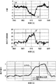
- FIG. 5 is a graph illustrating the temporal variation of the lateral G, the seated barycentric position, and their normalized values when the physical condition is normal.
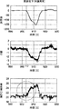
- FIG. 6 is a graph showing temporal fluctuations of the lateral G, the seating gravity center position, and their normalized values when the physical condition is abnormal.
- the physical condition determination unit 43 sets the horizontal G normalization data so that the initial value P of the horizontal G is 0 and the peak P ′ is 1 when the physical condition is normal. Normalize.
- the horizontal G peak P ′ is ⁇ 3G, so the physical condition determination unit 43 divides each value of the horizontal G normalization data by ⁇ 3 to obtain the normalization for horizontal G Normalize the data.
- Normalized data for horizontal G (hereinafter referred to as “normalized data for horizontal G”) is indicated by a bold line graph in the lower graph of FIG.
- the physical condition determination unit 43 also normalizes the data for normalizing the seating center of gravity position so that the initial value Q is 0 and the peak Q ′ is 1 in the same manner.
- the normalized data for normalization of the seating gravity center position (hereinafter referred to as “normalization data of the seating gravity center position”) is indicated by a thin line in the lower graph of FIG.
- the variation of the lateral G and the seating gravity center position is further clarified, and the time difference ⁇ t between the time t1 and the time t2 is further clarified.
- the physical condition determination unit 43 calculates the time difference ⁇ t when the normalized value of the normalized data of the lateral G and the seating gravity center position is 0.5. In the lower example of FIG. 5, the time difference ⁇ t is 450 ms, and the phase of the seating center of gravity position is 450 ms ahead of the phase of the lateral G. The physical condition determination unit 43 determines a physical condition abnormality by comparing the time difference ⁇ t indicating the preceding time with a predetermined time described later.
- the physical condition determination unit 43 similarly sets the normal value of the lateral G so that the initial value R of the lateral G is 0 and the peak R ′ is 1 when the physical condition is abnormal.
- the normalization data is normalized to generate horizontal G normalization data.
- the normalized data of the lateral G when the physical condition is abnormal is indicated by a thick line in the lower graph of FIG.
- the physical condition determination unit 43 normalizes the data for normalization of the seating center of gravity position so that the initial value S is 0 and the peak S ′ is 1 for the seating center of gravity position. To generate normalized data of the seating center of gravity position.
- the normalized data of the seating centroid position is indicated by a thin line in the lower graph of FIG.
- the time difference ⁇ t when the normalized value is 0.5 is ⁇ t ⁇ 0, and the phase of the seating center of gravity position is substantially the same as the phase of the lateral G. I understand.
- step S108 the physical condition determination unit 43 reads a predetermined time corresponding to the peak value of the lateral G from the map shown in FIG. 7 as a threshold for the time difference ⁇ t.
- FIG. 7 is a diagram showing a map used for determining a predetermined time corresponding to the horizontal G peak. This map is stored in advance in a memory (not shown), for example.
- the vertical axis defines a predetermined time and the horizontal axis defines a horizontal G peak.
- the predetermined time is a threshold for the time difference ⁇ t.
- the map of FIG. 7 is divided into two regions by a straight line X that rises to the right. Specifically, the region below the line X is a consciousness reduction (physical abnormality) region, and the region above the line X is a consciousness clear (normal physical condition) region.
- the line X passes through a point of a predetermined time of 0.05 s when the horizontal G peak is 0.1 G. Therefore, the physical condition determination unit 43 determines that the predetermined time as the threshold for the time difference ⁇ t is 0.05 s when the lateral G peak is 0.1 G. And the physical condition determination part 43 will determine with a driver
- the physical condition determination unit 43 adopts an aspect that does not determine whether there is an abnormality in physical condition when the lateral G is smaller than 0.1 G that is predetermined as a value that is likely to cause an erroneous determination. To do. Therefore, in the map of FIG. 7, the line X is not defined in the region where the lateral G is smaller than 0.1G.
- the predetermined time is set so that the predetermined time increases as the horizontal G peak increases. Therefore, this embodiment can accurately determine an abnormality in the driver's physical condition, as compared to a case where a mode in which the predetermined time is set constant is employed regardless of the size of the lateral G peak.
- the predetermined time is fixed to 0.07 s
- the area of 0.07 s or more is the consciousness clearing area
- the area smaller than 0.07 s is the consciousness lowering area.
- a point x in FIG. 7 indicates a point where the peak of the lateral G is 0.2 G, and the time difference ⁇ t between the timing t1 of the seating center of gravity position and the timing t2 of the lateral G is 0.09 s.
- the predetermined time is set to 0.1 s.
- step S109 the physical condition determination unit 43 determines whether the preceding time (time difference ⁇ t) of the timing t1 of the seating center of gravity position with respect to the time t of the lateral G is greater than the predetermined time read from the map in step S108. If the preceding time (time difference ⁇ t) is greater than the predetermined time (YES in step S109), the physical condition determination unit 43 determines that the driver's physical condition is normal (step S110), and the flow ends.
- step S111 the physical condition determination unit 43 causes the notification device 5 to notify the driver of information indicating abnormal physical condition (step S112), and ends the flow.
- step S112 the process returns to step S101. That is, the flowchart of FIG. 4 is repeated periodically.
- Embodiment 1 can detect a driver's physical condition abnormality earlier. Therefore, the first embodiment makes it possible to notify the driver of an abnormal physical condition at an early stage, and allows the driver to take measures to evacuate the vehicle to a safe place at an early stage, thereby improving safety. Can be made.
- the driver's physical condition detection device 1 according to Embodiment 2 Next, the driver's physical condition detection device 1 according to Embodiment 2 will be described.
- the same components as those in the first embodiment are denoted by the same reference numerals and description thereof is omitted.
- the driver physical condition detection device 1 according to the second embodiment further includes a front camera 6 indicated by an imaginary line in FIGS.
- the front camera 6 is provided, for example, on the front grill of the vehicle as shown in FIG.
- the front camera 6 has an optical axis directed to the front of the vehicle, for example, and acquires image data of the forward travel path by photographing the forward travel path at a predetermined sampling interval, and outputs the image data to the control unit 4.
- the front camera 6 may be disposed at any position other than the front grille of the vehicle as long as the front traveling path can be imaged.
- the front camera 6 may be provided on the roof of the vehicle, or may be provided in the vicinity of the headlight.
- the center-of-gravity position variation detection unit 41 acquires the seating surface pressure distribution of the driver from the seat weight sensor 2, detects the seating center-of-gravity position from the acquired seating surface pressure distribution, and Store in memory.
- the determination criterion acquisition unit 42 acquires the lateral G of the vehicle from the lateral G sensor 3, and stores it in a memory (not shown).
- step S203 the determination criterion acquisition unit 42 determines whether or not the lateral G is 0.1G or more. If the lateral G is smaller than 0.1G (NO in step S203), the process returns to step S201. In other words, the processes in steps S201 to S202 are repeated until it is determined in step S203 that the lateral G is 0.1 G or more.
- step S203 when the lateral G is 0.1 G or more (YES in step S203), the center-of-gravity position variation detection unit 41 acquires the driver's seat pressure distribution from the seat weight sensor 2, and the acquired seat pressure distribution is obtained.
- the seating barycentric position is calculated from the above and stored in a memory not shown (step S204).
- step S205 the determination criterion acquisition unit 42 acquires the lateral G of the vehicle from the lateral G sensor 3, and stores it in a memory (not shown).
- step S206 the determination criterion acquisition unit 42 acquires image data of the road ahead of the vehicle from the front camera 6, detects a travel line from the acquired image data, and stores data indicating the travel line in a memory (not shown). To do.
- Travel line refers to a wavy line or a solid line painted in white or yellow on the shoulder of the travel path and the center in the width direction in order to guide the travel zone of the vehicle.
- standard acquisition part 42 should just detect a travel line from the image data of a front travel path by applying a well-known white line detection process as a process which detects a travel line.
- step S207 the physical condition determination unit 43 determines whether or not the acquisition of normalization data has been completed. If the acquisition of normalization data has not been completed (NO in step S207), the process proceeds to step S204. return. That is, the processing of step S204 to step S206 is repeated until the acquisition of normalization data is completed.
- step S207 When the acquisition of normalization data is completed in step S207 (YES in step S207), the physical condition determination unit 43 normalizes the lateral G and the driver's seating gravity center position, as in the first embodiment. Normalization processing is performed on the business data (step S208).
- step S209 the curvature of the forward travel path is calculated from the travel line of the forward travel path of the vehicle detected in step S206 (step S209), and the process proceeds to step S210.
- step S210 the physical condition determination unit 43 reads a predetermined time corresponding to the curvature calculated in step S209 from an unillustrated map.
- the map used in the second embodiment is the map shown in FIG. 7, the horizontal axis adopts the curvature, the vertical axis adopts the predetermined time, the area above the line X is the consciousness clear area, the line X The lower area is set as the low consciousness area.
- Embodiment 2 can determine a driver's physical condition abnormality accurately like Embodiment 1.
- step S211 the physical condition determination unit 43 determines whether the preceding time (time difference ⁇ t) of the timing t1 of the seating center of gravity position with respect to the time t of the lateral G is larger than the predetermined time read from the map not shown in step S210. Determine whether or not. If the preceding time (time difference ⁇ t) is greater than the predetermined time read from the map (YES in step S211), the physical condition determination unit 43 determines that the physical condition of the driver is normal (step S212), and ends the flow.
- the physical condition determination unit 43 determines that the driver's physical condition is abnormal because the driver's preliminary movement is delayed. (Step S213).
- the physical condition determination unit 43 causes the notification device 5 to notify the driver of information indicating abnormal physical condition (step S214), and ends the flow.
- the process returns to step S201. That is, the flowchart of FIG. 8 is repeated periodically.
- the driver Is determined to be abnormal. Therefore, it is possible to determine the abnormality of the driver's physical condition using an appropriate value for a predetermined time in consideration of the start timing of the preliminary movement that varies according to the curvature of the curve.
- the driver's physical condition detection device 1 according to the third embodiment is different from the driver physical condition detection device 1 according to the first embodiment. Is determined.
- the driver's physical condition detection device 1 according to the third embodiment includes the front camera 6 described in the second embodiment.
- the same components as those in the first and second embodiments are denoted by the same reference numerals, and the description thereof is omitted.
- the seating center-of-gravity position variation model 44 is stored in advance in, for example, a memory included in the control unit 4.
- the seating center-of-gravity position variation model 44 includes time-series data indicating the variation of the seating center-of-gravity position for each curvature when the physical condition of the driver is normal.
- This time-series data may be calculated, for example, by averaging, for each curvature, a waveform that indicates a change in the seating gravity center position during a past turn of a driver who is on the same vehicle.
- this time-series data may be obtained by, for example, performing an experiment to acquire time-series data indicating fluctuations in the position of the center of gravity of a plurality of drivers during a turn, and averaging the waveform indicated by the time-series data for each curvature. It may be calculated by
- the determination criterion acquisition unit 42 acquires the seating gravity center position variation model 44 from a memory (not shown). Then, the physical condition determination unit 43 uses the timing t3 of the variation period of the seating gravity center position when the driver is normal, which is indicated by the seating gravity center position variation model 44 acquired by the determination criterion acquisition unit 42, as the determination reference time. Then, the physical condition determination unit 43 identifies the delay time of the timing t1 of the variation period of the sitting gravity center position detected by the gravity center position variation detection unit 41 with respect to the time t3 as the time difference ⁇ t, and when the time difference ⁇ t is equal to or longer than the predetermined time, the driving is performed. It is determined that the person's physical condition is abnormal.
- the seating center-of-gravity position variation model 44 is an example of variation information of the seating center-of-gravity position when the driver is normal due to a change in vehicle acceleration.
- step S301 of FIG. 9 the driver's seating surface pressure distribution is acquired from the seat weight sensor 2, the seating barycentric position is detected from the acquired seating surface pressure distribution, and stored in a memory (not shown).
- step S302 the determination criterion acquisition unit 42 acquires the lateral G of the vehicle from the lateral G sensor 3, and stores it in a memory (not shown).
- step S303 the determination criterion acquisition unit 42 determines whether or not the lateral G is 0.1G or more. If the lateral G is smaller than 0.1G (NO in step S303), the process returns to step S301. In other words, the processes in steps S301 to S302 are repeated until it is determined in step S303 that the lateral G is 0.1 G or more.
- step S303 when the lateral G is 0.1 G or more (YES in step S303), the gravity center position fluctuation detection unit 41 acquires the driver's seat pressure distribution from the seat weight sensor 2, and the acquired seat pressure distribution is obtained.
- the seating barycentric position is calculated from the above and stored in a memory (not shown) (step S304).
- step S305 the determination criterion acquisition unit 42 acquires the lateral G of the vehicle from the lateral G sensor 3, and stores it in a memory (not shown).
- step S306 the determination criterion acquisition unit 42 detects a travel line on the front travel path of the vehicle from the image data acquired by the front camera 6, and stores data indicating the travel line in a memory (not shown).
- step S307 the physical condition determination unit 43 determines whether or not acquisition of physical condition determination data has been completed. If acquisition of physical condition determination data has not been completed (NO in step S307), the process proceeds to step S304. return. That is, the processes in steps S304 to S306 are repeated until acquisition of physical condition determination data is completed.
- the physical condition determination data corresponds to time-series data of actually measured seating gravity center positions. Further, the physical condition determination unit 43 performs processing for detecting a peak for the seating center of gravity position, and when time series data from the start of the change of the seating center of gravity position to at least the peak can be acquired, acquisition of the physical condition determination data is performed. What is necessary is just to determine with having completed.
- step S307 when acquisition of the physical condition determination data is completed (YES in step S307), the determination reference acquisition unit 42 calculates the curvature of the forward travel path from the travel line detected in step S305 (step S308).
- step S309 the determination criterion acquisition unit 42 reads the seating gravity center position variation model 44 corresponding to the curvature calculated in step S308 from a memory (not shown).
- FIG. 10 is a graph showing the temporal transition of the seated center of gravity position indicated by the seated center of gravity position variation model 44 and the actually measured seated center of gravity position, where the vertical axis represents the seated center of gravity position, and the horizontal axis represents time. .
- a graph a indicated by a dotted line indicates a temporal transition of the seating gravity center position indicated by the seating gravity center position variation model 44
- a graph b indicated by a solid line indicates a temporal transition of the actually measured seating gravity center position.
- the change time t0 indicates the change start time of the lateral G.
- the seating center-of-gravity position variation model 44 information indicating this change time t0 is included in advance.
- the time series data of the actually measured seating center of gravity position also includes information on the change time t0.
- the physical condition determination unit 43 detects the change start time from the actually measured lateral G, determines the change start time as the change time t0 in the actually measured seating center of gravity position, and uses the information as the actually measured seating center of gravity position. It may be included in the time series data.
- step S310 the physical condition determination unit 43 displays the graph so that the change time t0 in the seating gravity center position variation model 44 acquired in step S309 matches the change time t0 in the seating gravity center position actually measured in step S304. Position a and graph b.
- the physical condition determination unit 43 calculates a time difference ⁇ t between the graph a and the graph b at the seating gravity center position p ′ that is 1 ⁇ 2 of the peak value of the graph a or the graph b (Step S310). Specifically, the physical condition determination unit 43 detects the time t3 when the seating gravity center position shown in the graph a reaches the seating gravity center position p ′. In addition, the physical condition determination unit 43 detects a time t1 when the seating gravity center position shown in the graph b reaches the seating gravity center position p ′. And the physical condition determination part 43 calculates the difference of the time t1 and the time t3 as time difference (DELTA) t.
- DELTA time difference
- time t3 corresponds to an example of a third time corresponding to the first time (time t1) within the fluctuation period of the seating gravity center position when the driver is normal.
- the physical condition determination unit 43 indicates that the preliminary operation is delayed, and thus determines that the physical condition of the driver is abnormal (step S312).
- the physical condition determination unit 43 may execute the process of step S310 using the predetermined time corresponding to the sitting gravity center position variation model 44 read in step S309.
- step S313 the physical condition determination unit 43 causes the notification device 5 to notify the driver of information indicating abnormal physical condition, and ends the flow.
- step S311 determines that the driver's physical condition is normal (step S311) and ends the flow. Note that when the flow of FIG. 9 ends, the process returns to step S301. That is, the flowchart of FIG. 9 is periodically repeated.
- the abnormal physical condition of the driver is determined using the seating center-of-gravity position variation model 44 that indicates the variation of the normal seating center-of-gravity position acquired in advance through experiments or the like. Therefore, Embodiment 3 can reduce the processing load of the control unit 4 and can determine the presence or absence of an abnormality of the driver earlier.
- the present invention can employ the following modifications.
- the seating gravity center position variation model 44 is provided for each curvature, but the present invention is not limited to this, and may be provided for each vehicle acceleration.
- the curvature of the front travel path of the vehicle is calculated based on the travel line of the front travel path captured by the front camera 6, but the present invention is not limited to this. It may be calculated by using map information of a navigation system mounted on the vehicle.
- the predetermined time used as the threshold value of the time difference ⁇ t has a different value depending on the peak or curvature of the lateral G, but the present invention is not limited to this, and the lateral time It may have a constant value regardless of the peak or curvature of G.
- the process for determining the presence or absence of an abnormality in the physical condition of the driver has not been performed, but the present invention is not limited to this, Regardless of the value of the lateral G, processing for determining the presence or absence of an abnormality in the physical condition of the driver may be performed.
- the line X shown in FIG. 7 is extended until it intersects the horizontal axis.
- the timing t1 and the timing t2 when the normalized value is 0.5 are used as the first timing and the second timing.
- the invention is not limited to this, and the change start time of the seating gravity center position may be adopted as the first time, and the change start time of the lateral G may be adopted as the second time.
- the half value of the peak of the graph a or the graph b is adopted as the seating gravity center position p ′, but the present invention is limited to this. Instead, a value other than 1.2 may be adopted.
- the time t3 of the graph a at the seating gravity center position p ′ is adopted as the third time
- the time t1 of the graph b at the seating gravity center position p ′ as the first time.
- the present invention is not limited to this.
- the change start time of the graph a may be adopted as the third time
- the change start time of the graph b may be adopted as the first time.
- a driver's physical condition detection device includes a center-of-gravity position variation detection unit that detects a variation in a driver's seating center-of-gravity position; A determination reference acquisition unit for acquiring determination reference information for determining a physical condition abnormality of the driver; The variation in the seating center of gravity position detected by the center of gravity position variation detection unit is compared with the variation in the determination criterion information acquired by the determination criterion acquisition unit, the first time within the variation period of the seating center of gravity position, and the determination criterion A physical condition determining unit that determines an abnormality in the physical condition of the driver based on a time difference from the determination reference time included in the information.
- the driver's physical condition abnormality is determined based on the time difference between the first time in the variation period of the seating center of gravity position and the determination reference time included in the determination reference information.
- this aspect focuses on the fact that when the physical condition of the driver is abnormal, the preliminary motion indicated by the change in the seating center of gravity position is delayed compared to when the physical condition is normal. A driver's physical condition abnormality can be detected earlier. Therefore, this aspect makes it possible to prompt the driver to take measures such as retreating the vehicle to a safe place by notifying this, thereby improving safety.
- the determination criterion acquisition unit acquires vehicle acceleration as the determination criterion information
- the physical condition determination unit uses, as the determination reference time, the second time corresponding to the first time within the acceleration variation period acquired by the determination reference acquisition unit, and the first time with respect to the second time. It is preferable that the preceding time is specified as the time difference and it is determined that the physical condition of the driver is abnormal when the time difference is equal to or less than a predetermined time.
- the acceleration of the vehicle is used as the determination reference information, and the second time corresponding to the first time within the acceleration fluctuation period is set as the determination reference time.
- this aspect determines with a driver
- the acceleration acquired by the determination reference acquisition unit is preferably a lateral acceleration of the vehicle.
- This aspect employs the lateral acceleration of the vehicle as the acceleration acquired by the determination reference acquisition unit.
- a support member for maintaining the driver's posture is not provided in the width direction of the vehicle seat. Therefore, it is expected that the change in the seating gravity center position with respect to the lateral acceleration has a higher correlation than the change in the seating gravity center position with respect to the vertical acceleration.
- the lateral acceleration of the vehicle having a high correlation with the change in the seating center of gravity position is detected, it is possible to accurately detect whether the driver's physical condition is normal or abnormal.
- the determination criterion acquisition unit acquires a curvature of a traveling road ahead of the vehicle as the determination criterion information
- the physical condition determination unit determines abnormality of the driver's physical condition using the predetermined time that is determined in advance according to the magnitude of the curvature acquired by the determination reference acquisition unit.
- the determination criterion acquisition unit acquires in advance fluctuation information of the seating gravity center position of the driver when the driver accompanies normal change as the determination criterion information
- the physical condition determination unit includes a third time corresponding to the first time within a variation period of the seating center of gravity position when the driver is normal, which is included in the variation information of the seating center of gravity position acquired by the determination criterion acquisition unit.
- the delay time of the first time with respect to the third time is specified as the time difference, and the physical condition of the driver is determined to be abnormal when the time difference is equal to or greater than a predetermined time.
- the driver's physical condition abnormality can be detected only by comparing the time-series data indicating the variation in the actually measured seating gravity center position and the time-series data indicating the variation in the normal seating gravity center position obtained in advance through experiments or the like. It is possible to determine, the processing burden is reduced, and the driver's physical condition abnormality can be determined earlier.
- the determination criterion acquisition unit includes an acceleration sensor that detects acceleration of the vehicle, It is preferable that the physical condition determination unit does not determine an abnormal physical condition of the driver when the acceleration detected by the acceleration sensor is equal to or less than a predetermined value.
- the acceleration detected by the acceleration sensor is equal to or less than a predetermined value, the abnormality of the driver's physical condition is not determined. It is possible to prevent erroneous determination due to abnormality determination.
- the seat weight sensor further includes a seat weight sensor that is installed on the seat surface of the driver's seat and includes a plurality of piezoelectric elements,
- the center-of-gravity position variation detection unit preferably detects the seating center-of-gravity position based on the pressure distribution of the seat surface detected by the seat weight sensor.
- the seat surface pressure distribution is detected by using a seat weight sensor that is provided on the seat surface of the driver's seat and includes a plurality of piezoelectric elements, and the seating gravity center position is detected from the pressure distribution. Therefore, this aspect can accurately determine the seating gravity center position.
- the camera may further include a front camera that captures a forward travel path of the vehicle.
- the determination reference acquisition unit detects a travel line of the front travel path from image data captured by the front camera, and calculates the curvature based on the detected travel line.
- the traveling line of the forward traveling road is detected from the image data taken by the front camera and the curvature of the forward traveling road is calculated based on the detected traveling line, the curvature can be accurately calculated.
- the apparatus further includes a memory that stores in advance the fluctuation information of the seating gravity center position at the normal time.
- the variation information of the sitting gravity center position is stored in the memory, the variation information of the sitting gravity center position can be quickly acquired.
- the present invention can detect an abnormal condition of the driver at an early stage, it can be suitably used in the field of vehicle safety technology.
Landscapes
- Engineering & Computer Science (AREA)
- Health & Medical Sciences (AREA)
- Life Sciences & Earth Sciences (AREA)
- Transportation (AREA)
- Mechanical Engineering (AREA)
- Biophysics (AREA)
- Medical Informatics (AREA)
- Physiology (AREA)
- Dentistry (AREA)
- Oral & Maxillofacial Surgery (AREA)
- Physics & Mathematics (AREA)
- Chemical & Material Sciences (AREA)
- Aviation & Aerospace Engineering (AREA)
- Pathology (AREA)
- Biomedical Technology (AREA)
- Heart & Thoracic Surgery (AREA)
- Combustion & Propulsion (AREA)
- Molecular Biology (AREA)
- Surgery (AREA)
- Animal Behavior & Ethology (AREA)
- General Health & Medical Sciences (AREA)
- Public Health (AREA)
- Veterinary Medicine (AREA)
- Seats For Vehicles (AREA)
- Auxiliary Drives, Propulsion Controls, And Safety Devices (AREA)
- Measurement Of The Respiration, Hearing Ability, Form, And Blood Characteristics Of Living Organisms (AREA)
- Traffic Control Systems (AREA)
Abstract
本発明は、より早期に運転者の体調異常を検出することができる運転者体調検知装置を提供する。 運転者体調検知装置(1)は、運転者の着座重心位置の変動を検出する重心位置変動検出部(41)と、運転者の体調異常を判定するための判定基準情報を取得する判定基準取得部(42)と、重心位置変動検出部(41)が検出した着座重心位置の変動と判定基準取得部(42)が取得した判定基準情報の変動とを対比し、着座重心位置の変動期間内の第1時期と、判定基準情報が示す判定基準時期との時間差に基づいて、運転者の体調異常を判定する体調判定部(43)とを備える。
Description
本発明は、車両の安全技術の分野に関するものであり、特に、車両を運転する運転者の体調検知を行う運転者体調検知装置に関するものである。
車両の安全技術の一環として、運転者の運転姿勢又は車両の挙動に基づいて運転者の体調異常を検出する技術が知られている。
例えば、特許文献1には、運転者の運転姿勢から体調異常を検出する技術が開示されている。具体的には、特許文献1には、運転席に配備された体圧分布センサにより運転者の臀部および背部の体圧分布を検出し、その検出結果に基づいて運転者の姿勢が適正姿勢範囲にあるか否かを判定し、運転者の体調異常の有無を検出する技術が開示されている。
また、特許文献2には、車両の挙動に基づいて運転者の体調異常を検出する技術が開示されている。具体的には、特許文献2には、自車両の走行位置及び走行車線から推定した通常走行域に対して自車両が逸脱したか否かを判定し、逸脱した場合、その後の操舵状態に基づいて運転者の覚醒度の低下を判定することで、運転者の体調異常を検出する技術が開示されている。
しかしながら、特許文献1に記載の技術では、運転者の運転姿勢自体に大きな変化が現れるのは、運転者の体調異常がある程度以上進行した後である。また、このことは、特許文献2に記載の技術による車両の挙動に基づいて運転者の体調異常を検出する場合も同様である。したがって、いずれの先行技術文献においても、運転者に安全な場所へ退避させるなどの対処を可能とするためには、より早期に運転者の体調異常を検出することが重要である。
本発明は、より早期に運転者の体調異常を検出することを目的とする。
本発明の一態様に係る運転者体調検知装置は、運転者の着座重心位置の変動を検出する重心位置変動検出部と、
前記運転者の体調異常を判定するための判定基準情報を取得する判定基準取得部と、
前記重心位置変動検出部が検出した着座重心位置の変動と前記判定基準取得部が取得した判定基準情報の変動とを対比し、前記着座重心位置の変動期間内の第1時期と、前記判定基準情報に含まれる判定基準時期との時間差に基づいて、前記運転者の体調異常を判定する体調判定部とを備える。
前記運転者の体調異常を判定するための判定基準情報を取得する判定基準取得部と、
前記重心位置変動検出部が検出した着座重心位置の変動と前記判定基準取得部が取得した判定基準情報の変動とを対比し、前記着座重心位置の変動期間内の第1時期と、前記判定基準情報に含まれる判定基準時期との時間差に基づいて、前記運転者の体調異常を判定する体調判定部とを備える。
本態様によれば、より早期に運転者の体調異常を検出することができる。
(本発明に至る知見)
本件出願人は、旋回時、又は、急な加速若しくは減速時等の車両の挙動変化に対して、運転者は足を踏ん張る又はハンドルを握る力を強めるなどの身構える動作を予備動作として行うことを見出した。更に、本件出願人は、この予備動作が体調異常の初期段階における若干の意識低下によって遅れることを見出した。
本件出願人は、旋回時、又は、急な加速若しくは減速時等の車両の挙動変化に対して、運転者は足を踏ん張る又はハンドルを握る力を強めるなどの身構える動作を予備動作として行うことを見出した。更に、本件出願人は、この予備動作が体調異常の初期段階における若干の意識低下によって遅れることを見出した。
そして、本件出願人は、この予備動作と前記のような車両の挙動とを関連させて運転者の体調異常を推定する場合、運転者の体調に起因する車両の挙動の変化のみ或いは運転姿勢の変化のみから運転者の体調異常を推定する場合よりも早期に体調異常を検出できるとの仮説を立て、下記の実験を行った。
図11A、図11Bは、その実験の結果を示すグラフである。図11Aは、意識清明状態(体調正常)における、車両旋回時の操舵角、車両の横方向の加速度(以下、横Gと記す)、及び運転者の着座重心位置のそれぞれの時間変動を示すグラフである。図11Bは、意識低下状態(体調異常)における、車両旋回時の操舵角、横G、及び運転者の着座重心位置のそれぞれの時間変動を示すグラフである。
これらのグラフによれば、図11Aの上段及び中段のグラフ並びに図11Bの上段及び中段のグラフに示すように、意識清明状態及び意識低下状態では、共に、操舵角の変化に連動して横Gが変動していることが分かる。しかし、図11Aの下段のグラフに示すように、意識清明状態では、横Gが急激に低下する時期t11に先行して、着座重心位置の変動が開始されていることが分かる。すなわち、横Gの変動に対して、着座重心位置の変動が先に生じており、カーブ進入時における運転者の予備動作がカーブへの侵入前に余裕を持って実施されていることが分かる。
これに対して、意識低下状態では、図11Bの下段のグラフに示すように、横Gが急激に低下する時期t12とほぼ同時に運転者の着座重心位置の変動が生じていることが分かる。
すなわち、本件出願人は、意識低下状態では、操舵自体は正常に行われていても、それに伴う横Gに対する予備動作は操舵開始前に余裕を持って実施されておらず、車両の挙動変化に対する予備動作の開始が遅延するという新たな知見を得た。
本発明はこのような知見に基づいてなされたものであり、以下、詳細に説明する。
(実施の形態1)
以下、本発明の運転者体調検知装置の実施形態について説明する。
以下、本発明の運転者体調検知装置の実施形態について説明する。
まず、図1により本実施形態に係る運転者体調検知装置1の構成を説明する。図1は、実施の形態1に係る運転者体調検知装置のブロック図である。運転者体調検知装置1は、シートウェイトセンサ2と、横Gセンサ3と、コントロールユニット4と、報知装置5とを備えている。なお、横Gセンサ3は加速度センサの一例である。
コントロールユニット4は、CPU又はASIC等のプロセッサと、メモリとを備えるコンピュータで構成されおり、プロセッサがメモリに記憶されたプログラムを実行することで、重心位置変動検出部41と、判定基準取得部42と、体調判定部43との機能を実現する。なお、これらの機能は、専用のハードウェア回路で実現されてもよい。
重心位置変動検出部41は、シートウェイトセンサ2から入力された座面圧力分布に基づき、着座重心位置の変動を検出する。
判定基準取得部42は、運転者の体調異常を判定するための判定基準情報を取得する。実施の形態1では、判定基準取得部42は、横Gセンサ3が検出した横Gを判定基準情報として取得する。
体調判定部43は、重心位置変動検出部41が検出した着座重心位置の変動と、判定基準取得部42が取得した判定基準情報の変動とを対比し、着座重心位置の変動期間内の第1時期と、判定基準情報に含まれる判定基準時期との時間差に基づいて、運転者の体調異常を判定する。
実施の形態1では、体調判定部43は、判定基準取得部42が検出した横Gの変動期間内の第1時期に対応する第2時期を判定基準時期として用い、第2時期に対する、第1時期の先行時間を時間差として特定し、時間差が所定時間以下のときに運転者の体調が異常であると判定する。
ここで、横Gの変動期間とは、図5の上段を参照して、0G付近からピークP’に向けて横Gの落ち込みが開始される変動開始時期から、ピークP’を経て再度0G付近に戻る変動終了時期までの期間が該当する。
また、着座重心位置の変動期間とは、図5の中段を参照し、着座重心位置がほぼ平坦に推移する領域からピークQ’に向けて上昇が開始される変動開始時期から、ピークQ’を経て再度平坦に推移する領域に戻る変動終了時期までの期間が該当する。
また、第1時期とは、図5の下段を参照し、例えば、着座重心位置が所定値(ここでは、正規化値で0.5)に到達した時期t1が該当する。
また、第1時期に対応する第2時期とは、図5の下段を参照し、例えば、横Gが所定値(ここでは、正規化値で0.5)に到達した時期t2が該当する。
なお、体調判定部43は、例えば、着座重心位置の変動開始時期を検知してから予め定められた一定期間が経過した時点を第1時期として検知し、横Gの変動開始時期を検知してから前記一定期間が経過した時点を第2時期として検知してもよい。
図2は、実施の形態1に係る運転者体調検知装置1が適用される車両の内部を上側から見たときの構成図である。図2に示すように、シートウェイトセンサ2は、運転席のシートクッション内に配置されている。シートウェイトセンサ2は、運転者の臀部が接する座面に設けられた複数の圧電素子から構成されている。シートウェイトセンサ2を構成する各圧電素子は、運転者の運転姿勢に応じた圧力を電圧信号に変換する。これにより、シートウェイトセンサ2は、運転者の座面圧力分布を検出する。なお、シートウェイトセンサ2は、例えば、運転者の座面圧力分布の検出を所定のサンプリング間隔で行い、検出した座面圧力分布を所定のサンプリング間隔でコントロールユニット4に出力する。
横Gセンサ3は、例えば、車両のセンターコンソールに配置された、少なくとも車幅方向(横方向の)の加速度成分が検知可能な加速度センサで構成されている。
重心位置変動検出部41は、シートウェイトセンサ2により検出された座面圧力分布に基づいて、運転者の着座重心位置の変動を検出する。図3は、シートウェイトセンサ2が検出する運転者の座面圧力分布の一例を示す図である。
座面圧力分布は、座面を構成する複数の位置のそれぞれの圧力値を含むデータ群で構成されている。図3の例では、座面を構成する複数の位置は、それぞれ、車両の前方を示すY座標と車両の幅方向を示すX座標との2次元の座標空間で表される。図3の例では、座面圧力分布は、同じ圧力値の位置が等値線で結ばれている。ここでは、座面圧力分布は、臀部の2つの頂点のそれぞれを中心に年輪状に拡散する複数の等値線で示されている。重心位置変動検出部41は、シートウェイトセンサ2から座面圧力分布が出力される都度、座面圧力分布の重心位置を座面重心位置として計算する。これにより、座面重心位置の時系列データが得られる。
報知装置5は、図2に示すように、例えば、インスツルメントパネルに設けられた表示装置で構成され、体調判定部43により運転者の体調が異常と判定された場合、そのことを示す情報を出力する。報知装置5は、例えば、「疲れていますので、少し休憩しましょう。」というような体調の異常を示すメッセージを表示装置に表示すればよい。また、報知装置5は、このようなメッセージを示す音声をスピーカから出力させてもよい。
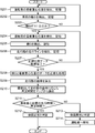
次に、前記コントロールユニット4による運転者の体調検知を図4のフローチャートを用いて説明する。
まず、ステップS101において、重心位置変動検出部41は、シートウェイトセンサ2から運転者の座面圧力分布を取得し、取得した座面圧力分布から着座重心位置を検出し、図略のメモリに記憶する。ステップS102において、判定基準取得部42は、横Gセンサ3から車両の横Gを取得し、図略のメモリに記憶する。
ステップS103において、判定基準取得部42は、横Gが0.1G以上か否かを判定し、横Gが0.1Gより小さい場合(ステップS103でNO)、処理をステップS101に戻す。すなわち、ステップS103において、横Gが0.1G以上であることが判定されるまで、ステップS101~ステップS102の処理が繰り返される。なお、この0.1Gは一例であり、横Gが変動が低いため着座重心位置が変動していないとみなせる値であれば0.1G以外の値が採用されてもよい。
ステップS103において、横Gが0.1以上の場合(ステップS103でYES)、重心位置変動検出部41は、シートウェイトセンサ2から運転者の座面圧力分布を取得し、取得した座面圧力分布から着座重心位置を算出し、図略のメモリに記憶する(ステップS104)。
ステップS105において、判定基準取得部42は、横Gセンサ3から車両の横Gを取得し、図略のメモリに記憶する。ステップS106において、体調判定部43は、体調の判定に用いる正規化用データの取得が完了したか否かを判定し、正規化用データの取得が完了していない場合(ステップS106でYES)、処理をステップS104へ戻す。すなわち、正規化用データの取得が完了するまで、ステップS104~ステップS105の処理が繰り返される。なお、体調判定部43は、例えば、横G及び運転者の着座重心位置のそれぞれについて、ピークを検出する処理を行い、変動の開始から少なくともピークに至るまでの時系列データが取得できた場合、正規化用データの取得が完了したと判定すればよい。
ステップS106において、正規化用データの取得が完了した場合(ステップS106でYES)、体調判定部43は、横G及び運転者の着座重心位置のそれぞれの正規化用データに対して正規化処理を行う(ステップS107)。正規化処理とは、それぞれ、単位が異なり、そのままでは、比較できない横G及び着座重心位置を無次元量化し、互いに比較できるようにする処理を指す。
ここで、図5及び図6を用いて正規化処理について説明する。図5は、体調の正常時における、横G、着座重心位置、及びこれらの正規化値のそれぞれの時間変動を示すグラフである。図6は、体調の異常時における、横G、着座重心位置、及びこれらの正規化値のそれぞれの時間変動を示すグラフである。
まず、図5の上段に示すように、体調判定部43は、体調の正常時における横Gの初期値Pを0とし、ピークP’が1となるように、横Gの正規化用データを正規化する。図5の上段の例では、横GのピークP’は-3Gなので、体調判定部43は、横Gの正規化用データの各値を-3で除することによって、横Gの正規化用データを正規化する。正規化された横Gの正規化用データ(以下、「横Gの正規化データ」と記す。)は図5の下段のグラフにおいて、太線のグラフで示されている。
また、図5の中段に示すように、体調判定部43は、着座重心位置も同様に、初期値Qを0とし、ピークQ’が1となるように着座重心位置の正規化用データを正規化する。正規化された着座重心位置の正規化用データ(以下、「着座重心位置の正規化データ」と記す。)は図5の下段のグラフにおいて、細線で示されている。
横G及び着座重心位置の正規化データ同士を比較することで、横G及び着座重心位置の変動がより明確化され、時期t1及び時期t2の時間差Δtもより明確化される。
図5の下段の例では、体調判定部43は、横G及び着座重心位置の正規化データの正規化値が0.5のときの時間差Δtが算出されている。図5の下段の例では、時間差Δtは450msであり、着座重心位置の位相は、横Gの位相よりも450ms先行している。体調判定部43は、この先行時間を示す時間差Δtと、後述する所定時間とを比較することで、体調異常を判定する。
また、図6の上段に示すように、体調の異常時においても同様に、体調判定部43は、横Gの初期値Rを0とし、ピークR’が1となるように、横Gの正規化用データを正規化して横Gの正規化データを生成する。体調の異常時の横Gの正規化データは、図6の下段のグラフにおいて、太線で示される。
また、図6の中段に示すように、体調判定部43は、着座重心位置についても、初期値Sを0とし、ピークS’が1となるように、着座重心位置の正規化用データを正規化して着座重心位置の正規化データを生成する。着座重心位置の正規化データは図6の下段のグラフにおいて、細線で示される。
図6の下段の例では、正規化値が0.5のときの時間差Δtは、Δt≒0となっており、着座重心位置の位相は横Gの位相に対してほぼ一致していることが分かる。
次に、ステップS108において、体調判定部43は、横Gのピーク値に対応する所定時間を時間差Δtに対する閾値として図7に示すマップから読み込む。
ここで、図7の横Gのピークに対応する所定時間を示すマップについて説明する。図7は、横Gのピークに対応する所定時間を決定するために用いられるマップを示す図である。このマップは、例えば、図略のメモリに予め記憶されている。図7に示すマップは、縦軸に所定時間、横軸に横Gのピークが規定されている。所定時間は、時間差Δtに対する閾値である。図7のマップは、右上がりの直線状のラインXによって2つの領域に分けられる。具体的には、ラインXよりも下側の領域は、意識低下(体調異常)領域であり、ラインXよりも上側の領域は、意識清明(体調正常)領域である。
例えば、ラインXは、横Gのピークが0.1Gのとき、所定時間が0.05sの点を通過している。そのため、体調判定部43は、横Gのピークが0.1Gのとき、時間差Δtに対する閾値としての所定時間を0.05sと決定する。そして、体調判定部43は、時間差Δtが0.05s以上であれば、運転者の体調は正常であると判定する。一方、体調判定部43は、時間差Δtが0.05sよりも小さければ、運転者の体調は異常と判定する。なお、旋回時の予備動作として運転者が行う着座重心位置の移動は、横Gが小さい場合には明確には現れない。したがって、横Gが小さい場合に、体調の異常の有無を判定すると誤判定を招く可能性がある。そこで、本実施の形態では、体調判定部43は、誤判定を招く可能性が高い値として予め定められた0.1Gよりも横Gが小さい場合、体調の異常の有無を判定しない態様を採用する。そのため、図7のマップでは、ラインXは横Gが0.1Gより小さい領域において規定されていない。
また、横Gのピークが大きくなるにつれて、運転者の予備動作の開始時期が早まり、その結果、着座重心位置の変動開始時期も早まることが想定される。そこで、図7のマップでは、横Gのピークが大きくなるにつれて所定時間が増大するように、所定時間が設定されている。そのため、本実施の形態は、横Gのピークの大きさに関わらず、所定時間を一定に設定した態様を採用する場合に比べ、運転者の体調異常を精度良く判定することができる。
例えば、図7の破線で示すように、横Gのピークにかかわらず、所定時間を0.07sに固定し、0.07s以上の領域を意識清明領域、0.07sより小さい領域を意識低下領域と設定した場合を考察する。
例えば、図7の点xは、横Gのピークが0.2Gであり、着座重心位置の時期t1と横Gの時期t2との時間差Δtが0.09sである点を示している。所定時間を0.07sで固定する態様を採用した場合、点xの時間差Δt(=0.09s)は、所定時間(=0.07s)より大きいので、点xは意識清明領域に属すると判定されてしまう。これに対して、本実施の形態では、横Gのピークが0.2Gの場合、所定時間は0.1sに設定される。そのため、本実施の形態では、点xの時間差Δt(=0.09s)は、所定時間(=0.1s)より小さいので、点xは意識低下領域に属すると判定される。したがって、本実施の形態では、横Gのピークの大きさに関わらず所定時間を一定にする態様を採用した場合に比べて、運転者の体調異常をより正確に判定できる。
図4のフローチャートに戻る。ステップS109において、体調判定部43は、横Gの時期t2に対する、着座重心位置の時期t1の先行時間(時間差Δt)が、ステップS108でマップから読み込んだ所定時間より大きいか否かを判定する。先行時間(時間差Δt)が所定時間より大きい場合(ステップS109でYES)、体調判定部43は、運転者の体調は正常と判定し(ステップS110)、フローを終了する。一方、先行時間(時間差Δt)がステップS108でマップから読み込んだ所定時間以下の場合(ステップS109でNO)、体調判定部43は、運転者の予備動作が遅れているため、運転者の体調は異常と判定する(ステップS111)。次に、体調判定部43は、報知装置5に運転者へ体調異常を示す情報を報知させ(ステップS112)、フローを終了する。なお、図4のフローが終了すると処理はステップS101に戻る。すなわち、図4のフローチャートは周期的に繰り返される。
このように、実施の形態1によれば、横Gの変動期間内の時期t2に対する、運転者の着座重心位置の変動期間内の時期t1の先行時間(時間差Δt)が、所定時間より小さい場合、旋回時における予備動作が遅れているため、運転者の体調が異常と判定される。そのため、実施の形態1は、より早期に運転者の体調異常を検出することができる。したがって、実施の形態1は、体調異常を運転者に早期に報知することが可能となり、運転者に車両を安全な場所に退避させる処置を早期にとらせることが可能になり、安全性を向上させることができる。
(実施の形態2)
次に、実施の形態2に係る運転者体調検知装置1について説明する。なお、実施の形態2において実施の形態1と同一の構成要素には同一の符号を付し、説明を省く。実施の形態2に係る運転者体調検知装置1は、実施の形態1の構成に加え、図1及び図2に仮想線で示したフロントカメラ6を更に備えている。
次に、実施の形態2に係る運転者体調検知装置1について説明する。なお、実施の形態2において実施の形態1と同一の構成要素には同一の符号を付し、説明を省く。実施の形態2に係る運転者体調検知装置1は、実施の形態1の構成に加え、図1及び図2に仮想線で示したフロントカメラ6を更に備えている。
フロントカメラ6は、図2に示すように、例えば、車両のフロントグリルに設けられている。フロントカメラ6は、光軸が例えば車両前方に向けられており、所定のサンプリング間隔で前方走行路を撮影することで、前方走行路の画像データを取得し、コントロールユニット4へ出力する。ここで、フロントカメラ6は前方走行路が撮像できる位置であれば、車両のフロントグリル以外のどのような位置に配置されてもよい。例えば、フロントカメラ6は、車両のルーフに設けられてもよいし、ヘッドライトの近傍に設けられてもよい。
まず、図8のステップS201において、重心位置変動検出部41は、シートウェイトセンサ2から運転者の座面圧力分布を取得し、取得した座面圧力分布から着座重心位置を検出し、図略のメモリに記憶する。ステップS202において、判定基準取得部42は、横Gセンサ3から車両の横Gを取得し、図略のメモリに記憶する。
ステップS203において、判定基準取得部42は、横Gが0.1G以上か否かを判定し、横Gが0.1Gより小さい場合(ステップS203でNO)、処理をステップS201へ戻す。すなわち、ステップS203において、横Gが0.1G以上であることが判定されるまで、ステップS201~ステップS202の処理が繰り返される。
ステップS203において、横Gが0.1G以上の場合(ステップS203でYES)、重心位置変動検出部41は、シートウェイトセンサ2から運転者の座面圧力分布を取得し、取得した座面圧力分布から着座重心位置を算出し、図略のメモリに記憶する(ステップS204)。
ステップS205において、判定基準取得部42は、横Gセンサ3から車両の横Gを取得し、図略のメモリに記憶する。ステップS206において、判定基準取得部42は、フロントカメラ6から車両の前方走行路の画像データを取得し、取得した画像データから走行ラインを検出し、走行ラインを示すデータを図略のメモリに記憶する。
走行ラインとは、車両の走行ゾーンを案内するために、走行路の路肩及び幅方向の中央に白又は黄色で塗られた波線又は実線のことを指す。なお、判定基準取得部42は、走行ラインを検出する処理として公知の白線検知処理を適用して、前方走行路の画像データから走行ラインを検知すればよい。
ステップS207において、体調判定部43は、正規化用データの取得が完了したか否かを判定し、正規化用データの取得が完了していない場合(ステップS207でNO)、処理をステップS204に戻す。すなわち、正規化用データの取得が完了するまで、ステップS204~ステップS206の処理が繰り返される。
ステップS207において、正規化用データの取得が完了した場合(ステップS207でYES)、体調判定部43は、実施の形態1と同様に、横Gと運転者の着座重心位置とのそれぞれの正規化用データに対して正規化処理を行う(ステップS208)。
ステップS209において、ステップS206で検出した車両の前方走行路の走行ラインから前方走行路の曲率を算出し(ステップS209)、処理をステップS210に進める。
ステップS210において、体調判定部43は、ステップS209で算出した曲率に対応する所定時間を図略のマップから読み込む。ここでは、実施の形態2で用いられるマップは、図7に示すマップにおいて、横軸に曲率を採用し、縦軸に所定時間を採用し、ラインXより上側の領域を意識清明領域、ラインXより下側の領域を意識低下領域として設定されている。これにより、実施の形態2のマップは、実施の形態1のマップと同様な関係を持つことができる。具体的には、曲率(=1/曲率半径)が大きくなるほど前方走行路は急なカーブになる。そこで、実施の形態2では、横軸に曲率及び縦軸に所定時間が設定され、ラインX上に曲率に対応する所定時間が設定されたマップを採用する。これにより、実施の形態2は、実施の形態1と同様、運転者の体調異常を精度よく判定することができる。
ステップS211において、体調判定部43は、横Gの時期t2に対する、着座重心位置の時期t1の先行時間(時間差Δt)が、ステップS210で図略のマップから読み込んだ所定時間と比較して大きいか否かを判定する。そして、先行時間(時間差Δt)がマップから読み込んだ所定時間より大きい場合(ステップS211でYES)、体調判定部43は、運転者の体調は正常と判定し(ステップS212)、フローを終了する。一方、先行時間(時間差Δt)がマップから読み込んだ所定時間以下の場合(ステップS211でNO)、体調判定部43は、運転者の予備動作が遅れているため、運転者の体調は異常と判定する(ステップS213)。次に、体調判定部43は、報知装置5に運転者へ体調異常を示す情報を報知させ(ステップS214)、フローを終了する。なお、図8のフローが終了すると処理はステップS201に戻る。すなわち、図8のフローチャートは周期的に繰り返される。
以上説明したように、実施の形態2によれば、走行ラインから検出された先行走行路の曲率に応じた所定時間が決定され、時間差Δtが、決定された所定時間以下であれば、運転者の体調が異常と判定される。そのため、カーブの曲率に応じて変動する予備動作の開始タイミングを考慮に入れて適切な所定時間の値を用いて運転者の体調異常を判定できる。
(実施の形態3)
次に、実施の形態3に係る運転者体調検知装置1について説明する。実施の形態3に係る運転者体調検知装置1は、実施の形態1に係る運転者体調検知装置1に対して、体調判定部43が、着座重心位置変動モデル44を用いて運転者の体調異常を判定するものである。なお、実施の形態3に係る運転者体調検知装置1は実施の形態2で示したフロントカメラ6を備えている。なお、実施の形態3において、実施の形態1、2と同じ構成要素には同一の符号を付し、説明を省略する。着座重心位置変動モデル44は、例えば、コントロールユニット4が備えるメモリに予め記憶されている。着座重心位置変動モデル44は、運転者の体調が正常である時における曲率毎の着座重心位置の変動を示す時系列データで構成されている。この時系列データは、例えば、同一車両に搭乗する運転者の過去における旋回時の着座重心位置の変動を示す波形を曲率毎に平均化することで算出されてもよい。或いは、この時系列データは、例えば、旋回時の複数の運転者の着座重心位置の変動を示す時系列データを取得する実験を行い、この時系列データが示す波形を曲率毎に平均化することで算出されてもよい。
次に、実施の形態3に係る運転者体調検知装置1について説明する。実施の形態3に係る運転者体調検知装置1は、実施の形態1に係る運転者体調検知装置1に対して、体調判定部43が、着座重心位置変動モデル44を用いて運転者の体調異常を判定するものである。なお、実施の形態3に係る運転者体調検知装置1は実施の形態2で示したフロントカメラ6を備えている。なお、実施の形態3において、実施の形態1、2と同じ構成要素には同一の符号を付し、説明を省略する。着座重心位置変動モデル44は、例えば、コントロールユニット4が備えるメモリに予め記憶されている。着座重心位置変動モデル44は、運転者の体調が正常である時における曲率毎の着座重心位置の変動を示す時系列データで構成されている。この時系列データは、例えば、同一車両に搭乗する運転者の過去における旋回時の着座重心位置の変動を示す波形を曲率毎に平均化することで算出されてもよい。或いは、この時系列データは、例えば、旋回時の複数の運転者の着座重心位置の変動を示す時系列データを取得する実験を行い、この時系列データが示す波形を曲率毎に平均化することで算出されてもよい。
本実施の形態において、判定基準取得部42は、図略のメモリから着座重心位置変動モデル44を取得する。そして、体調判定部43は、判定基準取得部42が取得した着座重心位置変動モデル44が示す、運転者の正常時における着座重心位置の変動期間の時期t3を判定基準時期として用いる。そして、体調判定部43は、時期t3に対する、重心位置変動検出部41が検出した着座重心位置の変動期間の時期t1の遅延時間を時間差Δtとして特定し、時間差Δtが所定時間以上の場合、運転者の体調が異常であると判定する。なお、着座重心位置変動モデル44は、車両の加速変化に伴う運転者の正常時における着座重心位置の変動情報の一例である。
まず、図9のステップS301において、シートウェイトセンサ2から運転者の座面圧力分布を取得し、取得した座面圧力分布から着座重心位置を検出し、図略のメモリに記憶する。ステップS302において、判定基準取得部42は、横Gセンサ3から車両の横Gを取得し、図略のメモリに記憶する。
ステップS303において、判定基準取得部42は、横Gが0.1G以上か否かを判定し、横Gが0.1Gより小さい場合(ステップS303でNO)、処理をステップS301へ戻す。すなわち、ステップS303において、横Gが0.1G以上であることが判定されるまで、ステップS301~ステップS302の処理が繰り返される。
ステップS303において、横Gが0.1G以上の場合(ステップS303でYES)、重心位置変動検出部41は、シートウェイトセンサ2から運転者の座面圧力分布を取得し、取得した座面圧力分布から着座重心位置を算出し、図略のメモリに記憶する(ステップS304)。
ステップS305において、判定基準取得部42は、横Gセンサ3から車両の横Gを取得し、図略のメモリに記憶する。ステップS306において、判定基準取得部42は、フロントカメラ6が取得した画像データから車両の前方走行路の走行ラインを検出し、走行ラインを示すデータを図略のメモリに記憶する。
ステップS307において、体調判定部43は、体調判定用データの取得が完了したか否かを判定し、体調判定用データの取得が完了していない場合(ステップS307でNO)、処理をステップS304に戻す。すなわち、体調判定用データの取得が完了するまでステップS304~ステップS306の処理が繰り返される。なお、ここで、体調判定用データとは、実測された着座重心位置の時系列データが該当する。また、体調判定部43は、着座重心位置についてピークを検出する処理を行い、着座重心位置の変動の開始から少なくともピークに至るまでの時系列データが取得できた場合、体調判定用データの取得が完了したと判定すればよい。
ステップS307において、体調判定用データの取得が完了した場合(ステップS307でYES)、判定基準取得部42は、ステップS305で検出された走行ラインから前方走行路の曲率を算出する(ステップS308)。
ステップS309において、判定基準取得部42は、ステップS308で算出した曲率に対応する着座重心位置変動モデル44を図略のメモリから読み込む。図10は、着座重心位置変動モデル44が示す着座重心位置と実測された着座重心位置との時間的推移を示すグラフであり、縦軸は着座重心位置を示し、横軸は時間を示している。図10において、点線で示すグラフaは、着座重心位置変動モデル44が示す着座重心位置の時間的推移を示し、実線で示すグラフbは実測された着座重心位置の時間的推移を示している。
図10において、変化時点t0は横Gの変動開始時期を示している。着座重心位置変動モデル44において、この変化時点t0を示す情報が事前に含まれている。また、実測された着座重心位置の時系列データにおいても、変化時点t0の情報が含められている。ここで、体調判定部43は、実測された横Gから変動開始時期を検出し、その変動開始時期を実測された着座重心位置における変化時点t0として決定し、その情報を実測された着座重心位置の時系列データに含ませればよい。
そして、ステップS310において、体調判定部43は、ステップS309で取得した着座重心位置変動モデル44における変化時点t0と、ステップS304で実測された着座重心位置における変化時点t0とが一致するように、グラフaとグラフbとを位置決めする。
そして、体調判定部43は、グラフa又はグラフbのピーク値の1/2の着座重心位置p’におけるグラフaとグラフbとの時間差Δtを算出する(ステップS310)。詳細には、体調判定部43は、グラフaに示す着座重心位置が着座重心位置p’に到達する時期t3を検知する。また、体調判定部43は、グラフbに示す着座重心位置が着座重心位置p’に到達する時期t1を検知する。そして、体調判定部43は、時期t1と時期t3との差分を時間差Δtとして算出する。
ここで、時期t3は、運転者の正常時における着座重心位置の変動期間内の第1時期(時期t1)に対応する第3時期の一例に相当する。
そして、体調判定部43は、時間差Δtが所定時間以上であれば(ステップS310でYES)、予備動作が遅れていることを示すので、運転者の体調は異常と判定する(ステップS312)。この所定時間は、例えば、ステップS309で読み込まれた着座重心位置変動モデル44毎に異なる値が設定されている。したがって、体調判定部43は、ステップS309で読み込んだ着座重心位置変動モデル44に対応する所定時間を用いて、ステップS310の処理を実行すればよい。
ステップS313において、体調判定部43は、報知装置5に運転者へ体調異常を示す情報を報知させ、フローを終了する。
一方、ステップS310で時間差Δtが所定時間より小さい場合(ステップS310でNO)、体調判定部43は、運転者の体調は正常と判定し(ステップS311)、フローを終了する。なお、図9のフローが終了すると処理はステップS301に戻る。すなわち、図9のフローチャートは周期的に繰り返される。
このように、実施の形態3によれば、予め実験等により取得された正常時の着座重心位置の変動を示す着座重心位置変動モデル44を用いて、運転者の体調異常が判定されている。そのため、実施の形態3は、コントロールユニット4の処理負担を軽減でき、運転者の異常の有無をより早期に判定できる。
本発明は下記の変形例が採用できる。
(1)実施の形態3では、着座重心位置変動モデル44は曲率毎に設けられていたが、本発明はこれに限定されず、車両の加速度毎に設けられていてもよい。
(2)実施の形態2、3では、車両の前方走行路の曲率は、フロントカメラ6が撮像された前方走行路の走行ラインに基づいて算出されたが、本発明はこれに限定されず、車両に搭載されたナビゲーションシステムの地図情報を用いることで、算出されてもよい。
(3)実施の形態1~3では、時間差Δtの閾値として用いられる所定時間は、横Gのピーク又は曲率に応じて異なる値を有していたが、本発明はこれに限定されず、横Gのピーク又は曲率に拘わらず一定の値を有していてもよい。
(4)実施の形態1~3では、横Gが0.1G以下の場合、運転者の体調の異常の有無を判定する処理が実施されていなかったが、本発明はこれに限定されず、横Gの値に拘わらず、運転者の体調の異常の有無を判定する処理が実施されてもよい。この場合、図7に示すラインXは、横軸と交差するまで延長されることになる。
(5)実施の形態1では、図5の下段に示されるように、第1時期及び第2時期として正規化値が0.5のときの時期t1及び時期t2が用いられているが、本発明はこれに限定されず、第1時期として着座重心位置の変動開始時期が採用され、第2時期として横Gの変動開始時期が採用されてもい。
(6)実施の形態3では、図10に示すように、着座重心位置p’として、グラフa又はグラフbのピークの1/2の値が採用されているが、本発明はこれに限定されず、1.2以外の値が採用されてもよい。
(7)実施の形態3では、図10に示すように、第3時期として着座重心位置p’におけるグラフaの時期t3が採用され、第1時期として着座重心位置p’におけるグラフbの時期t1が採用されたが、本発明はこれに限定されない。例えば、第3時期として、グラフaの変動開始時期が採用され、第1時期としてグラフbの変動開始時期が採用されてもよい。
(本実施の形態の纏め)
(1)本発明の一態様に係る運転者体調検知装置は、運転者の着座重心位置の変動を検出する重心位置変動検出部と、
前記運転者の体調異常を判定するための判定基準情報を取得する判定基準取得部と、
前記重心位置変動検出部が検出した着座重心位置の変動と前記判定基準取得部が取得した判定基準情報の変動とを対比し、前記着座重心位置の変動期間内の第1時期と、前記判定基準情報に含まれる判定基準時期との時間差に基づいて、前記運転者の体調異常を判定する体調判定部とを備える。
(1)本発明の一態様に係る運転者体調検知装置は、運転者の着座重心位置の変動を検出する重心位置変動検出部と、
前記運転者の体調異常を判定するための判定基準情報を取得する判定基準取得部と、
前記重心位置変動検出部が検出した着座重心位置の変動と前記判定基準取得部が取得した判定基準情報の変動とを対比し、前記着座重心位置の変動期間内の第1時期と、前記判定基準情報に含まれる判定基準時期との時間差に基づいて、前記運転者の体調異常を判定する体調判定部とを備える。
本態様は、着座重心位置の変動期間内の第1時期と判定基準情報に含まれる判定基準時期との時間差に基づいて、運転者の体調異常を判定する。このように、本態様は、運転者の体調が異常である場合は、体調が正常である場合に比べて、着座重心位置の変動によって示される予備動作が遅延することに着目しているため、より早期に運転者の体調異常を検出することができる。そのため、本態様は、例えば、これを報知することによって車両を安全な場所に退避させるといった処置を早期に運転者にとらせることが可能となり、安全性を向上させることができる。
(2)上記態様において、前記判定基準取得部は、前記判定基準情報として車両の加速度を取得し、
前記体調判定部は、前記判定基準取得部が取得した前記加速度の変動期間内の前記第1時期に対応する第2時期を前記判定基準時期として用い、前記第2時期に対する、前記第1時期の先行時間を前記時間差として特定し、前記時間差が所定時間以下のときに前記運転者の体調が異常であると判定することが好ましい。
前記体調判定部は、前記判定基準取得部が取得した前記加速度の変動期間内の前記第1時期に対応する第2時期を前記判定基準時期として用い、前記第2時期に対する、前記第1時期の先行時間を前記時間差として特定し、前記時間差が所定時間以下のときに前記運転者の体調が異常であると判定することが好ましい。
本態様は、判定基準情報として車両の加速度を用い、加速度の変動期間内の前記第1時期に対応する第2時期を判定基準時期とする。そして、本態様は、前記第2時期に対する、前記第1時期の先行時間が所定時間以下の場合、運転者の体調が異常であると判定する。そのため、本態様は、運転者の体調が異常である場合は、体調が正常である場合に比べて着座重心位置の変動によって示される予備動作が遅延することに着目して、より早期に運転者の体調異常を検出することができる。
(3)上記態様において、前記判定基準取得部が取得する加速度は車両の横加速度であることが好ましい。
本態様は、判定基準取得部が取得する加速度として車両の横加速度が採用されている。通常、運転者の操作性を確保するため、車両のシートの幅方向には、運転者の姿勢を維持するための支持部材は設けられていない。そのため、横加速度に対する着座重心位置の変化は縦加速度に対する着座重心位置の変化よりも相関が高いことが見込まれる。本態様は、着座重心位置の変動に対して相関の高い車両の横加速度を検出しているため、運転者の体調の正常、異常を精度よく検出することができる。
(4)上記態様において、前記判定基準取得部は、前記判定基準情報として車両の前方走行路の曲率を取得し、
前記体調判定部は、前記判定基準取得部が取得した前記曲率の大きさに応じて予め定められた前記所定時間を用いて前記運転者の体調異常を判定することが好ましい。
前記体調判定部は、前記判定基準取得部が取得した前記曲率の大きさに応じて予め定められた前記所定時間を用いて前記運転者の体調異常を判定することが好ましい。
運転者の体調が異常であったとしても、旋回するカーブの曲率が大きいほど、運転者の予備動作である着座重心位置の変動タイミングが早くなることが見込まれる。したがって、カーブの曲率に拘わらず一律の同じ所定時間を用いて、運転者の体調異常を判定してしまうと、体調が異常であるにも拘わらず正常であると誤判定される可能性がある。そこで、本態様は、車両の曲率に応じた所定時間を用いて運転者の体調の異常の有無を判定する。そのため、本態様は、運転者の体調異常をより正確に判定できる。
(5)上記態様において、前記判定基準取得部は、前記判定基準情報として車両の加速度変化に伴う運転者の正常時の着座重心位置の変動情報を予め取得し、
前記体調判定部は、前記判定基準取得部が取得した前記着座重心位置の変動情報に含まれる前記運転者の正常時における着座重心位置の変動期間内の前記第1時期に対応する第3時期を前記判定基準時期として用い、前記第3時期に対する、前記第1時期の遅延時間を前記時間差として特定し、前記時間差が所定時間以上のときに運転者の体調が異常であると判定することが好ましい。
前記体調判定部は、前記判定基準取得部が取得した前記着座重心位置の変動情報に含まれる前記運転者の正常時における着座重心位置の変動期間内の前記第1時期に対応する第3時期を前記判定基準時期として用い、前記第3時期に対する、前記第1時期の遅延時間を前記時間差として特定し、前記時間差が所定時間以上のときに運転者の体調が異常であると判定することが好ましい。
本態様は、実測された着座重心位置の変動を示す時系列データと、予め実験等により取得した正常時の着座重心位置の変動を示す時系列データとを比較するだけで運転者の体調異常を判定することができ、処理負担が軽減され、運転者の体調異常をより早期に判定できる。
(6)上記態様において、前記判定基準取得部は、前記車両の加速度を検知する加速度センサを備え、
前記体調判定部は、前記加速度センサが検出した加速度が所定値以下のときは、運転者の体調異常を判定しないことが好ましい。
前記体調判定部は、前記加速度センサが検出した加速度が所定値以下のときは、運転者の体調異常を判定しないことが好ましい。
本態様は、加速度センサが検知した加速度が所定値以下のときは運転者の体調異常の判定を行わないため、予備動作が発生しないことが想定される所定値以下の加速度状態において運転者の体調異常を判定することによる誤判定を防止することができる。
(7)上記態様において、前記運転者のシートの座面に設置され、複数の圧電素子から構成されるシートウェイトセンサを更に備え、
前記重心位置変動検出部は、前記シートウェイトセンサにより検出された前記座面の圧力分布に基づいて前記着座重心位置を検出することが好ましい。
前記重心位置変動検出部は、前記シートウェイトセンサにより検出された前記座面の圧力分布に基づいて前記着座重心位置を検出することが好ましい。
本態様は、運転者のシートの座面に設けられた、複数の圧電素子から構成されるシートウェイトセンサを用いて座面の圧力分布を検出し、この圧力分布から着座重心位置を検出する。そのため、本態様は、着座重心位置を正確に判定できる。
(8)上記態様において、前記車両の前方走行路を撮影するフロントカメラを更に備え、
前記判定基準取得部は、前記フロントカメラが撮影した画像データから前記前方走行路の走行ラインを検出し、前記検出した走行ラインに基づいて前記曲率を算出することが好ましい。
前記判定基準取得部は、前記フロントカメラが撮影した画像データから前記前方走行路の走行ラインを検出し、前記検出した走行ラインに基づいて前記曲率を算出することが好ましい。
本態様は、フロントカメラが撮影した画像データから前方走行路の走行ラインを検出し、検出した走行ラインに基づいて前方走行路の曲率を算出しているため、前記曲率を正確に算出できる。
(9)上記態様において、前記正常時の着座重心位置の変動情報を予め記憶するメモリを更に備えることが好ましい。
本態様は、着座重心位置の変動情報がメモリに記憶されているため、着座重心位置の変動情報を速やかに取得できる。
本発明は、運転者の体調異常を早期に検出することができるため、車両の安全技術の分野に好適に利用できる。
Claims (9)
- 運転者の着座重心位置の変動を検出する重心位置変動検出部と、
前記運転者の体調異常を判定するための判定基準情報を取得する判定基準取得部と、
前記重心位置変動検出部が検出した着座重心位置の変動と前記判定基準取得部が取得した判定基準情報の変動とを対比し、前記着座重心位置の変動期間内の第1時期と、前記判定基準情報に含まれる判定基準時期との時間差に基づいて、前記運転者の体調異常を判定する体調判定部とを備える運転者体調検知装置。 - 前記判定基準取得部は、前記判定基準情報として車両の加速度を取得し、
前記体調判定部は、前記判定基準取得部が取得した前記加速度の変動期間内の前記第1時期に対応する第2時期を前記判定基準時期として用い、前記第2時期に対する、前記第1時期の先行時間を前記時間差として特定し、前記時間差が所定時間以下のときに前記運転者の体調が異常であると判定する請求項1に記載の運転者体調検知装置。 - 前記判定基準取得部が取得する加速度は車両の横加速度である請求項2に記載の運転者体調検知装置。
- 前記判定基準取得部は、前記判定基準情報として車両の前方走行路の曲率を取得し、
前記体調判定部は、前記判定基準取得部が取得した前記曲率の大きさに応じて予め定められた前記所定時間を用いて前記運転者の体調異常を判定する請求項2又は3に記載の運転者体調検知装置。 - 前記判定基準取得部は、前記判定基準情報として車両の加速度変化に伴う運転者の正常時の着座重心位置の変動情報を予め取得し、
前記体調判定部は、前記判定基準取得部が取得した前記着座重心位置の変動情報に含まれる前記運転者の正常時における着座重心位置の変動期間内の前記第1時期に対応する第3時期を前記判定基準時期として用い、前記第3時期に対する、前記第1時期の遅延時間を前記時間差として特定し、前記時間差が所定時間以上のときに運転者の体調が異常であると判定する請求項1に記載の運転者体調検知装置。 - 前記判定基準取得部は、前記車両の加速度を検知する加速度センサを備え、
前記体調判定部は、前記加速度センサが検出した加速度が所定値以下のときは、運転者の体調異常を判定しない請求項1から請求項5のいずれか1項に記載の運転者体調検知装置。 - 前記運転者のシートの座面に設置され、複数の圧電素子から構成されるシートウェイトセンサを更に備え、
前記重心位置変動検出部は、前記シートウェイトセンサにより検出された前記座面の圧力分布に基づいて前記着座重心位置を検出する、請求項1から請求項6のいずれか1項に記載の運転者体調検知装置。 - 前記車両の前方走行路を撮影するフロントカメラを更に備え、
前記判定基準取得部は、前記フロントカメラが撮影した画像データから前記前方走行路の走行ラインを検出し、前記検出した走行ラインに基づいて前記曲率を算出する、請求項4に記載の運転者体調検知装置。 - 前記正常時の着座重心位置の変動情報を予め記憶するメモリを更に備える請求項5記載の運転者体調検知装置。
Applications Claiming Priority (2)
| Application Number | Priority Date | Filing Date | Title |
|---|---|---|---|
| JP2016-227960 | 2016-11-24 | ||
| JP2016227960A JP6418225B2 (ja) | 2016-11-24 | 2016-11-24 | 運転者体調検知装置 |
Publications (1)
| Publication Number | Publication Date |
|---|---|
| WO2018096913A1 true WO2018096913A1 (ja) | 2018-05-31 |
Family
ID=62196158
Family Applications (1)
| Application Number | Title | Priority Date | Filing Date |
|---|---|---|---|
| PCT/JP2017/039879 Ceased WO2018096913A1 (ja) | 2016-11-24 | 2017-11-06 | 運転者体調検知装置 |
Country Status (2)
| Country | Link |
|---|---|
| JP (1) | JP6418225B2 (ja) |
| WO (1) | WO2018096913A1 (ja) |
Cited By (3)
| Publication number | Priority date | Publication date | Assignee | Title |
|---|---|---|---|---|
| WO2019235274A1 (ja) * | 2018-06-07 | 2019-12-12 | ソニー株式会社 | 制御装置、制御方法、プログラム、および移動体 |
| JP2023021206A (ja) * | 2021-07-31 | 2023-02-10 | 株式会社スマートドライブ | 情報処理方法、情報処理装置及びプログラム |
| WO2024219265A1 (ja) * | 2023-04-20 | 2024-10-24 | 住友電気工業株式会社 | 運転者状態判定装置、車載装置、運転者状態判定システム、運転者状態判定方法および運転者状態判定プログラム |
Citations (8)
| Publication number | Priority date | Publication date | Assignee | Title |
|---|---|---|---|---|
| JPH079879A (ja) * | 1993-06-28 | 1995-01-13 | Mitsubishi Motors Corp | 車両用覚醒度検出装置 |
| JPH11326084A (ja) * | 1998-05-12 | 1999-11-26 | Isuzu Motors Ltd | ドライバ状態検出装置 |
| JP2002008159A (ja) * | 2000-06-27 | 2002-01-11 | Isuzu Motors Ltd | ドライバ状態判定装置 |
| US20080012262A1 (en) * | 2006-06-23 | 2008-01-17 | Stefano Carabelli | Suspension tilting module for a wheeled vehicle and a wheeled vehicle equipped with said suspension tilting module |
| JP2010187810A (ja) * | 2009-02-17 | 2010-09-02 | Nissan Motor Co Ltd | 居眠り防止装置及び居眠り防止方法 |
| JP2012166579A (ja) * | 2011-02-09 | 2012-09-06 | Aisin Seiki Co Ltd | 状態判定装置、状態判定方法及びプログラム |
| JP2012254745A (ja) * | 2011-06-09 | 2012-12-27 | Toyota Motor Corp | 異常時対応運転制御の要否判定方法および異常時対応運転制御の要否判定に基づく運転制御装置 |
| JP2015182564A (ja) * | 2014-03-24 | 2015-10-22 | 日産自動車株式会社 | 乗員姿勢制御装置 |
Family Cites Families (2)
| Publication number | Priority date | Publication date | Assignee | Title |
|---|---|---|---|---|
| WO2003070504A1 (en) * | 2002-02-04 | 2003-08-28 | Cesium Ab | Method and means for measuring the interaction between driver and vehicle |
| US8521357B2 (en) * | 2010-04-26 | 2013-08-27 | Nissan North America, Inc. | Impaired operation detection method |
-
2016
- 2016-11-24 JP JP2016227960A patent/JP6418225B2/ja active Active
-
2017
- 2017-11-06 WO PCT/JP2017/039879 patent/WO2018096913A1/ja not_active Ceased
Patent Citations (8)
| Publication number | Priority date | Publication date | Assignee | Title |
|---|---|---|---|---|
| JPH079879A (ja) * | 1993-06-28 | 1995-01-13 | Mitsubishi Motors Corp | 車両用覚醒度検出装置 |
| JPH11326084A (ja) * | 1998-05-12 | 1999-11-26 | Isuzu Motors Ltd | ドライバ状態検出装置 |
| JP2002008159A (ja) * | 2000-06-27 | 2002-01-11 | Isuzu Motors Ltd | ドライバ状態判定装置 |
| US20080012262A1 (en) * | 2006-06-23 | 2008-01-17 | Stefano Carabelli | Suspension tilting module for a wheeled vehicle and a wheeled vehicle equipped with said suspension tilting module |
| JP2010187810A (ja) * | 2009-02-17 | 2010-09-02 | Nissan Motor Co Ltd | 居眠り防止装置及び居眠り防止方法 |
| JP2012166579A (ja) * | 2011-02-09 | 2012-09-06 | Aisin Seiki Co Ltd | 状態判定装置、状態判定方法及びプログラム |
| JP2012254745A (ja) * | 2011-06-09 | 2012-12-27 | Toyota Motor Corp | 異常時対応運転制御の要否判定方法および異常時対応運転制御の要否判定に基づく運転制御装置 |
| JP2015182564A (ja) * | 2014-03-24 | 2015-10-22 | 日産自動車株式会社 | 乗員姿勢制御装置 |
Cited By (4)
| Publication number | Priority date | Publication date | Assignee | Title |
|---|---|---|---|---|
| WO2019235274A1 (ja) * | 2018-06-07 | 2019-12-12 | ソニー株式会社 | 制御装置、制御方法、プログラム、および移動体 |
| US12233796B2 (en) | 2018-06-07 | 2025-02-25 | Sony Corporation | Control device and control method for adjustment of vehicle device |
| JP2023021206A (ja) * | 2021-07-31 | 2023-02-10 | 株式会社スマートドライブ | 情報処理方法、情報処理装置及びプログラム |
| WO2024219265A1 (ja) * | 2023-04-20 | 2024-10-24 | 住友電気工業株式会社 | 運転者状態判定装置、車載装置、運転者状態判定システム、運転者状態判定方法および運転者状態判定プログラム |
Also Published As
| Publication number | Publication date |
|---|---|
| JP6418225B2 (ja) | 2018-11-07 |
| JP2018083536A (ja) | 2018-05-31 |
Similar Documents
| Publication | Publication Date | Title |
|---|---|---|
| KR101646401B1 (ko) | 운전자의 졸음상태 판단 시스템 및 그 판단 방법 | |
| JP5974915B2 (ja) | 覚醒度検出装置、および覚醒度検出方法 | |
| KR101519748B1 (ko) | 운전자 부주의 판단 방법 및 이를 위한 판단 장치 | |
| US7450016B2 (en) | Driver fatigue assessment device and method | |
| US10561356B2 (en) | Driver's physical condition detection device and method | |
| JP4788624B2 (ja) | 不注意警告装置、不注意警告装置の車両機器制御方法及び車両制御装置のプログラム | |
| EP2402201B1 (en) | Inattention determining apparatus | |
| JP6323510B2 (ja) | 運転者体調検知装置及び方法 | |
| US20170305342A1 (en) | Vehicle-mounted alert system and alert control device | |
| US20160262682A1 (en) | Driver monitoring apparatus | |
| KR20140147233A (ko) | 차량의 주행 패턴을 이용한 졸음 운전 판단 장치 및 방법 | |
| JP2018133007A (ja) | 警報装置 | |
| KR20130083373A (ko) | 차량 충돌 안전 제어 장치 및 방법 | |
| JP2004133749A (ja) | 顔の向き検知装置 | |
| JP7192668B2 (ja) | 覚醒度判定装置 | |
| JP2005087284A (ja) | 覚醒状態判定装置及び覚醒状態判定方法 | |
| JP6418225B2 (ja) | 運転者体調検知装置 | |
| JP2017206173A (ja) | ドライバ状態検出装置 | |
| JP2004041485A (ja) | 開閉眼モニタ装置 | |
| JP2020184138A (ja) | ドライバ異常姿勢検出装置 | |
| US10458787B2 (en) | System and method for measuring direction of face of driver in vehicle | |
| JP2008250859A (ja) | 覚醒度判定装置 | |
| CN109823344B (zh) | 驾驶提示方法与系统 | |
| JP2012166579A (ja) | 状態判定装置、状態判定方法及びプログラム | |
| JP4534789B2 (ja) | 車両用警報装置 |
Legal Events
| Date | Code | Title | Description |
|---|---|---|---|
| 121 | Ep: the epo has been informed by wipo that ep was designated in this application |
Ref document number: 17874930 Country of ref document: EP Kind code of ref document: A1 |
|
| NENP | Non-entry into the national phase |
Ref country code: DE |
|
| 122 | Ep: pct application non-entry in european phase |
Ref document number: 17874930 Country of ref document: EP Kind code of ref document: A1 |