WO2018094612A1 - 触控装置 - Google Patents
触控装置 Download PDFInfo
- Publication number
- WO2018094612A1 WO2018094612A1 PCT/CN2016/106931 CN2016106931W WO2018094612A1 WO 2018094612 A1 WO2018094612 A1 WO 2018094612A1 CN 2016106931 W CN2016106931 W CN 2016106931W WO 2018094612 A1 WO2018094612 A1 WO 2018094612A1
- Authority
- WO
- WIPO (PCT)
- Prior art keywords
- touch
- touch panel
- substrate
- sub
- hole
- Prior art date
- Legal status (The legal status is an assumption and is not a legal conclusion. Google has not performed a legal analysis and makes no representation as to the accuracy of the status listed.)
- Ceased
Links
Images



Classifications
-
- G—PHYSICS
- G06—COMPUTING OR CALCULATING; COUNTING
- G06F—ELECTRIC DIGITAL DATA PROCESSING
- G06F3/00—Input arrangements for transferring data to be processed into a form capable of being handled by the computer; Output arrangements for transferring data from processing unit to output unit, e.g. interface arrangements
- G06F3/01—Input arrangements or combined input and output arrangements for interaction between user and computer
- G06F3/03—Arrangements for converting the position or the displacement of a member into a coded form
- G06F3/041—Digitisers, e.g. for touch screens or touch pads, characterised by the transducing means
-
- G—PHYSICS
- G06—COMPUTING OR CALCULATING; COUNTING
- G06F—ELECTRIC DIGITAL DATA PROCESSING
- G06F1/00—Details not covered by groups G06F3/00 - G06F13/00 and G06F21/00
- G06F1/16—Constructional details or arrangements
- G06F1/20—Cooling means
-
- H—ELECTRICITY
- H05—ELECTRIC TECHNIQUES NOT OTHERWISE PROVIDED FOR
- H05K—PRINTED CIRCUITS; CASINGS OR CONSTRUCTIONAL DETAILS OF ELECTRIC APPARATUS; MANUFACTURE OF ASSEMBLAGES OF ELECTRICAL COMPONENTS
- H05K7/00—Constructional details common to different types of electric apparatus
- H05K7/20—Modifications to facilitate cooling, ventilating, or heating
Definitions
- the present invention relates to the field of touch manufacturing technologies, and in particular, to a touch device.
- the present application provides a touch device, and the technical problem that can be solved is to make the touch device maintain good sensitivity.
- the present application provides a touch device that includes a touch panel that opens a plurality of through holes that avoid the touch electrodes.
- the touch panel is curved.
- the touch panel is convexly curved.
- the touch panel includes a stacked substrate and a sensing film, wherein the substrate and the sensing film are respectively provided with a first sub-via hole regularly arranged, and a first sub-via on the substrate
- the first sub-vias of the sensing film are in one-to-one correspondence and constitute the through holes.
- the hydrophobic film is attached to the substrate, and the second thin via hole corresponding to the first sub-via of the substrate and the sensing film is disposed on the hydrophobic film, and the substrate and the sensing film are A sub-via and the second sub-via form the via.
- the substrate includes an inner surface and a touch surface opposite to the inner surface, the hydrophobic film is attached to the touch surface of the substrate, and the sensing film is attached to the inner surface.
- the sensing film comprises a substrate, an intermediate layer and a conductive layer sequentially stacked on the substrate, and the conductive layer comprises a touch electrode avoiding the through hole.
- the substrate and the sensing film are pasted by an adhesive.
- an air flow passage is formed in the through hole, and the air flow passes through the air flow passage in the air exit direction.
- the airflow flows from the non-touch side of the touch panel toward the touch side of the touch panel, and the non-touch side and the touch side are located on opposite sides of the touch panel.
- the non-touch side of the touch panel is provided with a fan, and the fan generates the airflow.
- the device further includes an outer casing connected to the touch panel, and the fan is housed in the outer casing.
- the outer casing includes a cavity and an opening, the fan is received in the cavity, and the touch panel closes the opening.
- the diameter of the through hole is smaller than the width of the finger.
- the diameter of the through hole is less than 3 mm.
- the through holes are arranged in a matrix on the touch panel.
- the touch device by opening a through hole on the touch panel to avoid the touch electrode, the water droplets on the touch object can be drained, thereby improving the touch sensitivity of the touched object.
- the touch device is provided with a fan, and the water on the touch surface is dried by the through hole on the touch panel, so that the water stain on the user's hand on the touch surface of the touch panel can be dried to ensure the hand. Without water, you can avoid the influence of moisture on the touch and improve the touch sensitivity.
- FIG. 1 is a perspective view of a touch device of the present invention.
- FIG. 2 is an exploded view of the touch device shown in FIG. 1.
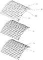
- FIG. 3 is a schematic diagram of a touch panel of the touch device shown in FIG. 1 .
- FIG. 4 is a schematic view of another embodiment of the touch panel of the touch device shown in FIG. 1 .
- FIG. 5 is a schematic view showing the state of use of the touch control device shown in FIG. 1.
- FIG. 5 is a schematic view showing the state of use of the touch control device shown in FIG. 1.
- the present invention provides a touch device including a housing 10 that is housed in a housing 10 .
- the touch panel 30 is disposed on the touch panel 30 and the touch panel 30 is disposed on the touch panel 30.
- the touch panel 30 is provided with a touch sensor (not shown).
- the touch panel 30 avoids the touch sensor.
- a plurality of through holes 31 are arranged at positions of the touch electrodes, and a plurality of the through holes 31 and the inside of the outer casing 10 penetrate the exhaust air for the fan 20.
- a plurality of the 31 through holes are arranged in a matrix on the touch panel 30.
- the touch panel 30 has a convex curved shape, and the touch surface is convex and convex.
- the touch panel 30 is in the form of a flat plate.
- the touch panel 30 has a curved plate shape to facilitate the flow of water stains, and the surface of the panel is formed with a uniform through hole 31 to facilitate the scattering of water stains when the high speed wind passes.
- the touch panel 30 includes a stacked substrate 32 and a sensing film 33 .
- the substrate 32 is a curved plate including an inner surface 321 and a touch surface 322 opposite the inner surface 321 .
- the touch surface 322 has a convex arc shape as an operation surface of the touch panel 30.
- the sensing film 33 is attached to the inner surface 321 .
- the substrate 32 is provided with a plurality of first sub-vias 323 arranged in a regular manner.
- the plurality of first sub-vias 323 are arranged in a matrix.
- the first sub-vias 331 are regularly arranged on the sensing film 33.
- the plurality of first sub-vias 331 are arranged in a matrix.
- the first sub-vias 323 on the substrate 32 are in one-to-one correspondence with the first sub-vias 331 of the sensing film 33.
- the substrate 32 and the sensing film 33 are pasted by the adhesive 35.
- the sensing film 33 includes a substrate, an intermediate layer and a conductive layer which are sequentially laminated on the substrate.
- the conductive layer includes a plurality of touch electrodes. The touch electrodes and the leads of the touch electrodes avoid the first sub-vias 331 to avoid reducing the touch sensing capability.
- a hydrophobic film 34 is disposed on the substrate 32, and the second sub-pass corresponding to the first sub-via 331 of the substrate 32 and the first sub-via 331 of the sensing film 33 is disposed on the hydrophobic film 34.
- the hole 341, the first sub-via 323 of the substrate 32 and the first sub-via 331 and the second sub-pass 341 of the sensing film 33 constitute the through-hole 31.
- the hydrophobic film 34 is attached to the touch surface 322.
- a hydrophobic film 34 is attached to the outermost layer of the substrate 32. The hydrophobic film 34 ensures that the touch surface is not in contact with the water stain, and the water stain can be prevented from remaining on the touch surface of the substrate 32.
- the outer casing 10 is a rectangular box body, and is provided with a cavity 12 and an opening (not shown).
- the fan 20 is mounted in the cavity, and the touch panel 30 covers the opening.
- Sealing that is, the outer casing 10 fixes the touch panel 30 and the high speed fan 20 and ensures that the wind pressure does not leak.
- the fan 20 is a high speed fan, preferably having a wind speed of 90 m/s.
- the high-speed wind blown by the fan 20 reaches the surface of the touch panel 30 through the circular through hole 31, that is, the touch surface, and can blow the water stain on the hand to ensure that the hand does not touch the water, thereby not affecting the touch panel. 30 touch sensitivity.
- the hydrophobic film 34 is omitted, and the first sub-via 323 and the sensing film 33 on the substrate 32 are omitted.
- the first sub-via 331 constitutes the through hole 31.
- the first sub-via 323 and the first sub-via 331 are circular through-holes.
- the diameter of the through hole 31 is smaller than the width of the finger.
- An air flow passage is formed in the through hole 31, and the air flow passes through the air flow passage in the air blowing direction.
- the airflow flows from the non-touch side of the touch panel 30 toward the touch side of the touch panel 30, and the non-touch side and the touch side are located on opposite sides of the touch panel.
- the wind of the fan is blown from the inside of the casing 10 to the touch panel 30. Since the touch panel 30 is convexly curved, the wind blown from the dense through hole 31 has a very high flow velocity as the finger approaches the touch panel 30.
- the blown water droplet is blown dry before being touched to the touch surface due to the high wind speed, or is blown to the area of the touch panel 30.
- the finger touches the touch panel 30 the water of the finger is substantially dried, thereby ensuring the accuracy and sensitivity of the touch.
- the touch device of the present application is provided with a fan, and the water of the touch surface is air-dried through a through hole on the touch panel; specifically, the circular touch panel 30 has a circular shape uniformly distributed in a matrix.
- the through hole 31, the high-speed wind blown by the fan of the bottom casing 10 of the touch panel 30 reaches the surface of the touch panel through the circular through hole 31, and the water stain on the user's hand on the touch surface 322 of the touch panel can be Blow dry to ensure that the hands are not touched with water, which can avoid moisture affecting the touch effect and improve touch sensitivity.
- the touch panel is curved and has a hydrophobic film 34 on the surface, the water residue can be further prevented, that is, the water on the user's hand cannot be touched on the touch surface 322, thereby achieving the user's hand. Touch operation of water does not affect touch sensitivity.
- the touch device of the present invention may also not include the fan 20, and only relies on the through hole 31 to guide the water on the finger. That is, after the finger touches the touch panel 30, the water on the finger drops into the outer casing 10 from the through hole 31, so that no water is generated on the surface of the touch panel 30, and the water can be prevented. Water droplets affect the effect of touch sensitivity. In particular, since the touch panel 30 is convexly curved, the water droplets are more likely to move under the action of gravity, increasing the probability of dropping into the through holes 31. Of course, it is also feasible that the touch panel 30 has a flat or concave arc shape, but the efficiency is not as remarkable as that of the convex arc surface.
Landscapes
- Engineering & Computer Science (AREA)
- Theoretical Computer Science (AREA)
- General Engineering & Computer Science (AREA)
- Physics & Mathematics (AREA)
- Human Computer Interaction (AREA)
- General Physics & Mathematics (AREA)
- Thermal Sciences (AREA)
- Microelectronics & Electronic Packaging (AREA)
- Position Input By Displaying (AREA)
- Push-Button Switches (AREA)
Abstract
本申请提供的一种触控装置,其包括触控面板,触控面板开设避开触控电极的多个通孔。所述的触控装置设置风扇,通过在触控面板上的通孔进行对触控面的水进行风干,可以将在出空面板的触控面上使用者手上的水渍吹干,保证手上不沾水,提高触控灵敏度。
Description
本发明涉及触控制造技术领域,尤其涉及一种触控装置。
现存的触控装置,如触控传感器等,触控面板全部采用封闭平面形式,即触控部分都是一个完整的平面或曲面,这种触控结构的缺点在于当触控表面沾水或使用者手上沾水使用后会影响触控的灵敏性甚至使得触控完全失灵。
发明内容
基于上述问题,本申请提供一种触控装置,可以要解决的技术问题是使得触控装置保持很好的灵敏度。
本申请提供一种触控装置,其包括触控面板,触控面板开设避开触控电极的多个通孔。
其中,所述触控面板为弧形。
其中,所述触控面板为凸弧形。
其中,所述触控面板包括层叠设置的基板与感测膜,所述基板与所述感测膜上均设有规则排列的第一子通孔,并且所述基板上的第一子通孔与所述感测膜的第一子通孔一一对应并构成所述的通孔。
其中,所述基板上贴有疏水薄膜,所述疏水薄膜上设有与所述基板与感测膜的第一子通孔相对应的第二子通孔,所述基板与感测膜的第一子通孔与所述第二子通孔构成所述通孔。
其中,所述基板包括内表面及与所述内表面相对的触控面,所述疏水薄膜贴于所述基板的触控面,所述感测膜贴于所述内表面。
其中,所述感测膜包括基材,依次层叠于基材上的中间层及导电层,导电层包括避开通孔的触控电极。
其中,所述基板与感测膜通过粘着剂粘贴。
其中,所述通孔内形成气流通道,气流沿出风方向穿过气流通道。
其中,气流从触控面板的非触控侧朝向触控面板的触控侧流动,非触控侧与触控侧位于触控面板的相反的两侧。
其中,触控面板的非触控侧设有风扇,风扇产生所述气流。
其中,还包括与触控面板连接的外壳,风扇收容于外壳内。
其中,外壳包括腔体及开口,风扇收容于腔体内,触控面板封闭开口。
其中,通孔的直径小于手指的宽度。
其中,通孔的直径小于3mm。
其中,所述通孔在所述触控面板上呈矩阵排布。
本申请通过在触控面板上开设避开触控电极的通孔,可以疏导触控物上所沾的水滴,从而提升沾水的触控物的触控灵敏度。此外,触控装置设置风扇,通过在触控面板上的通孔进行对触控面的水进行风干,可以将在触控面板的触控面上使用者手上的水渍吹干,保证手上不沾水,可以避免水份影响触控效果,提高触控灵敏度。
为了更清楚地说明本发明实施例中的技术方案,下面将对实施例中所需要使用的附图作简单地介绍,显而易见地,下面描述中的附图仅仅是本发明的一些实施例,对于本领域普通技术人员来讲,在不付出创造性劳动的前提下,还可以根据这些附图获得其他的附图。
图1是本发明触控装置立体图。
图2是图1所示的触控装置分解图。
图3是图1所示的触控装置的触控面板示意图。
图4是图1所示的触控装置的触控面板另一实施方式示意图。
图5是图1所示触控触控装置使用状态示意图。
下面将结合本发明实施方式中的附图,对本发明实施方式中的技术方案进行清楚、完整地描述。
请参阅图1,本发明提供一种触控装置,其包括外壳10,收容于外壳10
内的风扇20及覆盖风扇20于外壳10内的触控面板30,所述触控面板30设有触控传感器(图未示),所述触控面板30上避开所述触控传感器的触控电极的位置排布有数个通孔31,数个所述通孔31与所述外壳10内部贯通用于所述风扇20的排风。本实施例中,数个所述31通孔在所述触控面板30上呈矩阵排布。
请参阅图2与图3,本实施例中,所述触控面板30为凸弧形板状,其触控面为外凸弧形。其他实施例中所述触控面板30为平板状。触控面板30为弧形板状便于水渍流动,面板表面制造出均布的通孔31,以便于高速风通过时吹散水渍。
请参阅图3,本实施例中,所述触控面板30包括层叠设置的基板32与感测膜33。基板32为弧形板,其包括内表面321及与内表面321相对的触控面322。所述触控面322为外凸弧形,作为所述触控面板30操作面。所述感测膜33贴于所述内表面321上。
所述基板32设有规则排列的数个第一子通孔323,本实施例中数个第一子通孔323呈矩阵排列。所述感测膜33上设有规则排列的第一子通孔331,本实施例中数个第一子通孔331呈矩阵排列。所述基板32上的第一子通孔323与所述感测膜33的第一子通孔331一一对应。
本实施例中,所述基板32与感测膜33通过粘着剂35粘贴。
本实施例中,所述感测膜33包括基材,依次层叠于基材上的中间层及导电层。导电层包括多个触控电极,这些触控电极及触控电极的引线均避开第一子通孔331以避免降低触控感测能力。
所述基板32上贴有疏水薄膜34,所述疏水薄膜34上设有与所述基板32的第一子通孔323与感测膜33的第一子通孔331相对应的第二子通孔341,所述基板32的第一子通孔323与感测膜33的第一子通孔331与所述第二子通341孔构成所述通孔31。具体的,所述疏水薄膜34贴于所述触控面322上。在基板32最外层贴上疏水薄膜34,疏水薄膜34保证触控表面与水渍不亲和,可以避免水渍残留在基板32的触控面。
本实施例中,所述外壳10为矩形盒体,设有腔体12及开口(图未标),所述风扇20装于所述腔体内,所述触控面板30盖于所述开口处并与外壳10
密封,也就是说外壳10将触控面板30与高速风扇20固定并保证风压不漏风。
参见图2,所述风扇20为高速风扇,优选为风速为90m/s。风扇20吹出的高速风通过圆形通孔31到达触控面板30的表面也就是触控面,并可以将人手上的水渍吹干,保证手上不沾水,从而不会影响触控面板30触控灵敏度。
请参阅图4,本申请另一实施例中,与上述实施例不同的是,本实施例中,省略疏水薄膜34,所述基板32上的第一子通孔323与所述感测膜33的第一子通孔331构成所述的通孔31。本实施例中,第一子通孔323及第一子通孔331为圆形通孔。
风扇风干触控面功能原理参见图6。通孔31的直径小于手指的宽度。所述通孔31内形成气流通道,气流沿出风方向穿过气流通道。气流从触控面板30的非触控侧朝向触控面板30的触控侧流动,非触控侧与触控侧位于触控面板的相反的两侧。所述风扇的风从外壳10内向触控面板30吹出,由于触控面板30是外凸弧形的,从密布的通孔31吹出的风整体具有极高的流速,当手指靠近触控面板30时,手指上的水被风朝侧向吹向手指的周围区域,由于风速较高,被吹落的水滴在到触控面之前已经被吹干,或者是被吹到触控面板30的区域之外,因此当手指接触到触控面板30时手指的水已基本被吹干,进而确保触控的精度及灵敏度。
本申请所述的触控装置设置风扇,通过在触控面板上的通孔进行对触控面的水进行风干;具体地说,弧形触控面板30上存在成矩阵均布的圆形的通孔31,触控面板30的底部外壳10的风扇吹出的高速风通过圆形通孔31到达触控面板表面,并可以将在触控面板的触控面322上使用者手上的水渍吹干,保证手上不沾水,可以避免水份影响触控效果,提高触控灵敏度。另外由于触控面板为弧形且表面具有一层疏水膜34,进一步能够避免水渍残留,也就是使用者手上所沾的水无法沾到触控面322上,从而达到使用者手上沾水进行触控操作不会影响触控灵敏度。
可以理解地,本发明的触控装置也可以不包含风扇20,仅依靠通孔31来疏导手指上的水。即当手指接触到触控面板30之后,手指上的水会从通孔31中滴落进外壳10内,从而使触控面板30表面不会产生积水,也可以起到防止
水滴影响触控灵敏度的效果。特别地,由于触控面板30是呈凸弧形,因而水滴更易在重力的作用下进行移动,增大滴落进通孔31的概率。当然,触控面板30呈平面或凹弧形也同样可行,但效率不如凸弧面显著。
Claims (16)
- 一种触控装置,其特征在于,包括触控面板,触控面板开设避开触控电极的多个通孔。
- 如权利要求1所述的触控装置,其特征在于,所述触控面板为弧形。
- 如权利要求1所述的触控装置,其特征在于,所述触控面板为凸弧形。
- 如权利要求1所述的触控装置,其特征在于,所述触控面板包括层叠设置的基板与感测膜,所述基板与所述感测膜上均设有规则排列的第一子通孔,并且所述基板上的第一子通孔与所述感测膜的第一子通孔一一对应并构成所述的通孔。
- 如权利要求4所述的触控装置,其特征在于,所述基板上贴有疏水薄膜,所述疏水薄膜上设有与所述基板与感测膜的第一子通孔相对应的第二子通孔,所述基板与感测膜的第一子通孔与所述第二子通孔构成所述通孔。
- 如权利要求5所述的触控装置,其特征在于,所述基板包括内表面及与所述内表面相对的触控面,所述疏水薄膜贴于所述基板的触控面,所述感测膜贴于所述内表面。
- 如权利要求4所述的触控装置,其特征在于,所述感测膜包括基材,依次层叠于基材上的中间层及导电层,导电层包括避开通孔的触控电极。
- 如权利要求4所述的触控装置,其特征在于,所述基板与感测膜通过粘着剂粘贴。
- 如权利要求1至8任一项所述的触控装置,其特征在于,所述通孔内形成气流通道,气流沿出风方向穿过气流通道。
- 如权利要求9所述的触控装置,其特征在于,气流从触控面板的非触控侧朝向触控面板的触控侧流动,非触控侧与触控侧位于触控面板的相反的两侧。
- 如权利要求10所述的触控装置,其特征在于,触控面板的非触控侧设有风扇,风扇产生所述气流。
- 如权利要求11所述的触控装置,其特征在于,还包括与触控面板连接的外壳,风扇收容于外壳内。
- 如权利要求12所述的触控装置,其特征在于,外壳包括腔体及开口,风扇收容于腔体内,触控面板封闭开口。
- 如权利要求1至8任一项所述的触控装置,其特征在于,通孔的直径小于手指的宽度。
- 如权利要求1至8任一项所述的触控装置,其特征在于,通孔的直径小于3mm。
- 如权利要求1至8任一项所述的触控装置,其特征在于,所述通孔在所述触控面板上呈矩阵排布。
Priority Applications (2)
| Application Number | Priority Date | Filing Date | Title |
|---|---|---|---|
| CN201680038940.7A CN107980112B (zh) | 2016-11-23 | 2016-11-23 | 触控装置 |
| PCT/CN2016/106931 WO2018094612A1 (zh) | 2016-11-23 | 2016-11-23 | 触控装置 |
Applications Claiming Priority (1)
| Application Number | Priority Date | Filing Date | Title |
|---|---|---|---|
| PCT/CN2016/106931 WO2018094612A1 (zh) | 2016-11-23 | 2016-11-23 | 触控装置 |
Publications (1)
| Publication Number | Publication Date |
|---|---|
| WO2018094612A1 true WO2018094612A1 (zh) | 2018-05-31 |
Family
ID=62004261
Family Applications (1)
| Application Number | Title | Priority Date | Filing Date |
|---|---|---|---|
| PCT/CN2016/106931 Ceased WO2018094612A1 (zh) | 2016-11-23 | 2016-11-23 | 触控装置 |
Country Status (2)
| Country | Link |
|---|---|
| CN (1) | CN107980112B (zh) |
| WO (1) | WO2018094612A1 (zh) |
Cited By (2)
| Publication number | Priority date | Publication date | Assignee | Title |
|---|---|---|---|---|
| CN111240535A (zh) * | 2020-01-13 | 2020-06-05 | 广西中沛光电科技有限公司 | 一种双面丝印导电薄膜结构的电容式触摸屏 |
| CN114032803A (zh) * | 2021-11-30 | 2022-02-11 | 江苏腾源智能科技有限公司 | 一种效率高的智能停车管理用厂内引导装置 |
Families Citing this family (1)
| Publication number | Priority date | Publication date | Assignee | Title |
|---|---|---|---|---|
| CN112423513B (zh) * | 2020-11-24 | 2022-06-24 | 北京枭龙防务科技有限公司 | 一种用于智能眼镜电路上的散热触摸板及智能眼镜 |
Citations (5)
| Publication number | Priority date | Publication date | Assignee | Title |
|---|---|---|---|---|
| CN201838274U (zh) * | 2010-10-12 | 2011-05-18 | 深圳市洲明科技股份有限公司 | Led显示屏模组 |
| CN202422619U (zh) * | 2011-12-23 | 2012-09-05 | 北京华晟丽晶科技有限公司 | 一种穿透式的柔性led显示屏模组 |
| CN202905053U (zh) * | 2012-10-09 | 2013-04-24 | 安徽四通显示科技股份有限公司 | 带镂空结构的led显示屏 |
| JP2015038588A (ja) * | 2013-08-19 | 2015-02-26 | 勝 齋藤 | 看板装置 |
| CN105425974A (zh) * | 2015-12-19 | 2016-03-23 | 镇江市智禾电子科技有限公司 | 一种具有制热暖手功能的键盘 |
Family Cites Families (4)
| Publication number | Priority date | Publication date | Assignee | Title |
|---|---|---|---|---|
| CN200944227Y (zh) * | 2006-08-30 | 2007-09-05 | 介面光电股份有限公司 | 触控面板的结构改良 |
| CN201638197U (zh) * | 2010-03-30 | 2010-11-17 | 毛肖林 | 一种鼓气结构的触控面板 |
| KR101092745B1 (ko) * | 2010-04-26 | 2011-12-09 | 한국전력공사 | 급속 충전기의 터치스크린 온도유지 장치 |
| CN201698382U (zh) * | 2010-07-23 | 2011-01-05 | 牧东光电(苏州)有限公司 | 气孔型触控板 |
-
2016
- 2016-11-23 CN CN201680038940.7A patent/CN107980112B/zh not_active Expired - Fee Related
- 2016-11-23 WO PCT/CN2016/106931 patent/WO2018094612A1/zh not_active Ceased
Patent Citations (5)
| Publication number | Priority date | Publication date | Assignee | Title |
|---|---|---|---|---|
| CN201838274U (zh) * | 2010-10-12 | 2011-05-18 | 深圳市洲明科技股份有限公司 | Led显示屏模组 |
| CN202422619U (zh) * | 2011-12-23 | 2012-09-05 | 北京华晟丽晶科技有限公司 | 一种穿透式的柔性led显示屏模组 |
| CN202905053U (zh) * | 2012-10-09 | 2013-04-24 | 安徽四通显示科技股份有限公司 | 带镂空结构的led显示屏 |
| JP2015038588A (ja) * | 2013-08-19 | 2015-02-26 | 勝 齋藤 | 看板装置 |
| CN105425974A (zh) * | 2015-12-19 | 2016-03-23 | 镇江市智禾电子科技有限公司 | 一种具有制热暖手功能的键盘 |
Cited By (3)
| Publication number | Priority date | Publication date | Assignee | Title |
|---|---|---|---|---|
| CN111240535A (zh) * | 2020-01-13 | 2020-06-05 | 广西中沛光电科技有限公司 | 一种双面丝印导电薄膜结构的电容式触摸屏 |
| CN111240535B (zh) * | 2020-01-13 | 2024-04-02 | 广西中沛光电科技有限公司 | 一种双面丝印导电薄膜结构的电容式触摸屏 |
| CN114032803A (zh) * | 2021-11-30 | 2022-02-11 | 江苏腾源智能科技有限公司 | 一种效率高的智能停车管理用厂内引导装置 |
Also Published As
| Publication number | Publication date |
|---|---|
| CN107980112A (zh) | 2018-05-01 |
| CN107980112B (zh) | 2020-12-18 |
Similar Documents
| Publication | Publication Date | Title |
|---|---|---|
| WO2018094612A1 (zh) | 触控装置 | |
| Mazzeo et al. | based, capacitive touch pads | |
| JP2013514589A5 (zh) | ||
| KR101093651B1 (ko) | 금속박막을 이용한 터치패널 및 그 제조방법 | |
| JP2020053067A (ja) | 力センサ付き入力デバイス | |
| BR102018012760B1 (pt) | Dispositivo eletrônico | |
| CN218354696U (zh) | 电子烟芯片及电子设备 | |
| CN104345953A (zh) | 显示装置 | |
| WO2015064438A1 (ja) | 薄膜の製造方法、透明導電膜 | |
| KR102082681B1 (ko) | 이물질 방지 장치 | |
| WO2018047936A1 (ja) | 容量型ガスセンサ | |
| CN104703522B (zh) | 手干燥装置 | |
| CN108279791B (zh) | 具有气压感测式按键的鼠标 | |
| CN204029675U (zh) | 导电体结构 | |
| JP6541889B2 (ja) | 手乾燥装置 | |
| TW201329824A (zh) | 薄型電容式觸摸屏 | |
| TW202115540A (zh) | 觸控面板 | |
| CN107214146B (zh) | 一种键盘 | |
| TWM485453U (zh) | 觸控面板結構 | |
| CN105867669A (zh) | 具有除湿结构的显示装置 | |
| CN219500435U (zh) | 一种电子烟 | |
| CN207529360U (zh) | 一种电容触摸屏 | |
| CN207315037U (zh) | 一种防水电子门锁 | |
| CN105842394B (zh) | 气体侦测装置 | |
| CN209559799U (zh) | 一种放大气体检测的tft电子元件工装 |
Legal Events
| Date | Code | Title | Description |
|---|---|---|---|
| 121 | Ep: the epo has been informed by wipo that ep was designated in this application |
Ref document number: 16922417 Country of ref document: EP Kind code of ref document: A1 |
|
| NENP | Non-entry into the national phase |
Ref country code: DE |
|
| 32PN | Ep: public notification in the ep bulletin as address of the adressee cannot be established |
Free format text: NOTING OF LOSS OF RIGHTS PURSUANT TO RULE 112(1) EPC (EPO FORM 1205 DATED 08/10/2019) |
|
| 122 | Ep: pct application non-entry in european phase |
Ref document number: 16922417 Country of ref document: EP Kind code of ref document: A1 |