WO2018093022A1 - Unité de socle de charge sans fil permettant un couplage multiple et système de charge sans fil comprenant ladite unité de socle - Google Patents
Unité de socle de charge sans fil permettant un couplage multiple et système de charge sans fil comprenant ladite unité de socle Download PDFInfo
- Publication number
- WO2018093022A1 WO2018093022A1 PCT/KR2017/009409 KR2017009409W WO2018093022A1 WO 2018093022 A1 WO2018093022 A1 WO 2018093022A1 KR 2017009409 W KR2017009409 W KR 2017009409W WO 2018093022 A1 WO2018093022 A1 WO 2018093022A1
- Authority
- WO
- WIPO (PCT)
- Prior art keywords
- wireless charging
- charging tray
- input
- connector portion
- tray unit
- Prior art date
Links
Images


Classifications
-
- H—ELECTRICITY
- H02—GENERATION; CONVERSION OR DISTRIBUTION OF ELECTRIC POWER
- H02J—CIRCUIT ARRANGEMENTS OR SYSTEMS FOR SUPPLYING OR DISTRIBUTING ELECTRIC POWER; SYSTEMS FOR STORING ELECTRIC ENERGY
- H02J50/00—Circuit arrangements or systems for wireless supply or distribution of electric power
- H02J50/005—Mechanical details of housing or structure aiming to accommodate the power transfer means, e.g. mechanical integration of coils, antennas or transducers into emitting or receiving devices
-
- H—ELECTRICITY
- H02—GENERATION; CONVERSION OR DISTRIBUTION OF ELECTRIC POWER
- H02J—CIRCUIT ARRANGEMENTS OR SYSTEMS FOR SUPPLYING OR DISTRIBUTING ELECTRIC POWER; SYSTEMS FOR STORING ELECTRIC ENERGY
- H02J50/00—Circuit arrangements or systems for wireless supply or distribution of electric power
- H02J50/10—Circuit arrangements or systems for wireless supply or distribution of electric power using inductive coupling
-
- H—ELECTRICITY
- H02—GENERATION; CONVERSION OR DISTRIBUTION OF ELECTRIC POWER
- H02J—CIRCUIT ARRANGEMENTS OR SYSTEMS FOR SUPPLYING OR DISTRIBUTING ELECTRIC POWER; SYSTEMS FOR STORING ELECTRIC ENERGY
- H02J50/00—Circuit arrangements or systems for wireless supply or distribution of electric power
- H02J50/40—Circuit arrangements or systems for wireless supply or distribution of electric power using two or more transmitting or receiving devices
-
- H—ELECTRICITY
- H02—GENERATION; CONVERSION OR DISTRIBUTION OF ELECTRIC POWER
- H02J—CIRCUIT ARRANGEMENTS OR SYSTEMS FOR SUPPLYING OR DISTRIBUTING ELECTRIC POWER; SYSTEMS FOR STORING ELECTRIC ENERGY
- H02J7/00—Circuit arrangements for charging or depolarising batteries or for supplying loads from batteries
- H02J7/0042—Circuit arrangements for charging or depolarising batteries or for supplying loads from batteries characterised by the mechanical construction
-
- H—ELECTRICITY
- H02—GENERATION; CONVERSION OR DISTRIBUTION OF ELECTRIC POWER
- H02J—CIRCUIT ARRANGEMENTS OR SYSTEMS FOR SUPPLYING OR DISTRIBUTING ELECTRIC POWER; SYSTEMS FOR STORING ELECTRIC ENERGY
- H02J7/00—Circuit arrangements for charging or depolarising batteries or for supplying loads from batteries
- H02J7/02—Circuit arrangements for charging or depolarising batteries or for supplying loads from batteries for charging batteries from ac mains by converters
Definitions
- the present invention relates to a wireless charging device capable of wirelessly charging power of a small electronic device such as a wireless charging smart phone and a wireless charging system including the same. More specifically, the present invention relates to a wireless charging tray unit modularized to enable various types of coupling and a wireless charging system configured to include the same.
- a rechargeable small electronic device such as a mobile device is exposed to the outside of the charging power input terminal connected to the battery, and is connected to the output terminal of the charger cable terminal to receive power from the charger to the battery.
- a foreign material such as dust or moisture enters the inside of the device to reduce the durability of the device, and the power input terminal itself is also contaminated so that the contact state is easily poor. have.
- the externally exposed power input terminal hurts the aesthetics of the device.
- Wireless charging technology is a technology for charging a battery by wirelessly supplying power without directly connecting a charger power cable to an electronic device.
- it has been applied to limited applications such as electric toothbrushes, home wireless phones, power tools, etc., but recently, it has become a technology that can conveniently charge mobile devices such as smartphones.
- the electromagnetic induction method supplies power to the transmission coil inside the charger and receives power from the battery-side power receiving coil within a few mm distance to charge the battery.
- the center of the power transmission coil and the power receiving coil should be aligned.
- the charging efficiency is up to 90% compared to the wired charging method.
- Magnetic resonance method is based on the resonance phenomenon of the magnetic field can be charged at a relatively long distance, but there is a debate about the harmful effects of electromagnetic waves generated.
- An example of the above-described electromagnetic induction type wireless charging technology may be Korean Patent No. 10-1315976.
- the present invention relates to an automatic positioning wireless charger and a charging method using the same, including: a transmission coil unit including a transmission coil generating an induced current in a reception coil of a portable terminal by an electromagnetic induction phenomenon; A power transmission circuit unit applying a current to the power transmission coil; A driving unit to move the position of the power transmission coil unit; And a control unit which stops the driving unit when the power transmission coil and the power receiving coil are aligned to decrease the voltage applied to the power transmission coil.
- This has an advantageous effect in terms of improving the charging efficiency by actively moving the position of the power transmission coil according to the position of the power receiving coil, but there is a limit that can not charge several devices at the same time.
- Japanese Laid-Open Patent Publication No. 2013-500692 discloses a configuration using a wireless charging technology of the electromagnetic induction method, to connect a plurality of wireless feeder modules to each other to charge a plurality of electronic devices at the same time.
- Such a configuration may be variously arranged and used according to a user's needs, and as the types of devices equipped with a wireless charging function are diversified, it is advantageous in terms of diversity and expandability of the usage form.
- the fact that the user can freely change the arrangement and the connection of the module may be a factor that reduces safety. This is because if the connection between the module and the module is incorrect or a short occurs due to a conductor contacting the output connector of the module, an overcurrent may flow and the device may be damaged, or heat generation and sparking may cause a more dangerous situation.
- An object of the present invention is to provide a wireless charging tray unit and a wireless charging system including the same.
- the wireless charging tray unit includes a case having a polygonal top and a plurality of side surfaces, and a power transmission coil disposed inside the case, the case through the power transmission coil
- a plurality of output connector units configured to transfer the rest of the power supplied through the connector unit to the outside except the power transmitted through the power transmission coil; It includes, and the permanent magnet is disposed on the input side, the plurality of output side are each attached metal is disposed in a position corresponding to the permanent magnet, the input connector of any one of the two wireless charging tray unit is different The electrical connection between the two connector portions is guided by the attractive force between the permanent magnet and the attachment metal when one output connector portion is coupled to each other.
- the input connector part includes a contact terminal electrode and a part of the case protruding from the input side
- the output connector part includes a contact terminal electrode and a part of the case is recessed from the output side. It may include an indentation structure.
- the input connector portion may include a permanent magnet disposed toward the front of the projecting structure
- the output connector portion may include an attachment metal disposed at a position corresponding to the permanent magnet toward the front of the recessed structure. Can be.
- the input connector unit may include a pair of permanent magnets disposed toward the front of the protruding structure, and the pair of permanent magnets may be disposed such that different polarities face the front, and the output connector unit includes: It may further include at least one permanent magnet disposed toward the front of the recess structure so that the attraction force between at least one of the pair of permanent magnets when normally coupled to the input connector portion.
- the wireless charging tray unit is disposed between the input connector portion and each of the plurality of output connector portions, and from the input connector portion only when the output connector portion is normally connected to the input connector portion of the other wireless charging tray unit.
- the apparatus may further include a safety switch for supplying power to the corresponding output connector.
- the safety switch is disposed adjacent to the metal attached to the output side, the magnetic sensing to operate by detecting a state in which the permanent magnets disposed in close proximity to each other on the input side of the other wireless charging tray unit attached to the metal attached; It may include a device.
- the wireless charging tray unit includes a case having a polygonal top surface and a plurality of side surfaces, and a power transmission coil disposed inside the case, the vicinity of the upper surface of the case through the power transmission coil
- a plurality of output connector units configured to transfer the rest of the power supplied through the connector unit to the outside except the power transmitted through the power transmission coil;
- a first permanent magnet is disposed on the input side, and the first attachment metal is disposed at a position corresponding to the first permanent magnet on each of the plurality of output side, and any one of two wireless charging tray units is provided.
- the electrical connection between the two connector portions is guided by the attraction force between the first permanent magnet and the first attachment metal when the input connector portion and the other output connector portion are coupled to each other.
- a second permanent magnet disposed forward in the protruding structure in which the case partially protrudes, and a second attachment metal disposed in correspondence with the second permanent magnet in the indent structure in which the case is partially embedded in the output connector part; It includes more.
- the power is disposed between the input connector portion and each of the plurality of output connector portions, and power is output from the input connector portion to the corresponding output connector portion only when the output connector portion is normally connected to the input connector portion of another wireless charging tray unit. It may further include a safety switch to be supplied.
- the safety switch is disposed adjacent to the second attachment metal, the magnetic sensing element is operated by detecting the state in which the second permanent magnet corresponding to each other of the other wireless charging tray unit is attached in close proximity to the second attachment metal. It may include.
- a wireless charging system configured to wirelessly charge a plurality of electronic devices at the same time the plurality of wireless charging tray unit is electrically connected to each other, the wireless charging tray unit is a polygonal shape
- a wireless charging tray unit including a case having a top surface and a plurality of side surfaces of the case and a power transmission coil disposed inside the case, and generating power by generating a magnetic field of a predetermined frequency near the top surface of the case through the power transmission coil, An input connector part formed to protrude from an input side, which is one of the plurality of side surfaces, and receiving power to be supplied to the power transmission coil from the outside; And a shape in which a plurality of output side surfaces of the plurality of side surfaces except the input side are embedded to correspond to the protruding shape of the input connector portion, and are electrically connected to the input connector portion in the case.
- a plurality of output connector units configured to transfer the rest of the power supplied through the connector unit to the outside except the power transmitted through the power transmission coil; It includes, and the permanent magnet is disposed on the input side, the plurality of output side are each attached metal is disposed in a position corresponding to the permanent magnet, the input connector of any one of the two wireless charging tray unit is different The electrical connection between the two connector portions is guided by the attractive force between the permanent magnet and the attachment metal when one output connector portion is coupled to each other.
- At least one of the plurality of wireless charging tray units is charged by receiving power from the input connector unit in the case, and the charged power in a state separated from other wireless charging tray units through the power transmission coil or an external output terminal.
- the auxiliary battery unit may further include an auxiliary battery combined wireless charging tray unit.
- the wireless charging tray unit may further include a display lamp disposed near the vertex of the polygonal shape, and the display lamp may be output from the power transmission coil since power is input to an input connector of each wireless charging tray unit.
- the electronic device may be controlled to be turned on until an external electronic device receiving power is detected.
- an input connector unit connected to any one of the output connector unit of the plurality of wireless charging tray unit, an output connector unit connected to the other input connector unit of the plurality of wireless charging tray unit, and the input connector unit
- a connection tray unit which transfers power between two different wireless charging tray units, including an internal wiring connecting the output connector unit.
- the user can arrange and use a plurality of modular wireless charging devices in various ways, while inducing an electrical correct connection and preventing the possibility of a wrong connection in advance to improve safety and convenience.
- a user arranges a plurality of wireless charging tray units in various types of combinations, an unintended contact with an external conductor such as a key or a coin, or a failure that occurs when the wrong direction is combined may occur. It is effective to prevent the risk of fever, such as the source.
- FIG. 1 shows an example of the use of a wireless charging system according to an embodiment of the present invention.
- FIG. 2 shows a wireless charging system according to the embodiment of FIG.
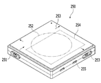
- Figure 3 shows a secondary battery combined wireless charging tray unit.
- FIG. 4 shows a configuration of a wireless charging tray unit according to an embodiment of the present invention.
- FIG. 5 shows in detail the output connector portion and the input connector portion of the wireless charging tray unit according to an embodiment of the present invention.
- Figure 6 shows in detail the coupling and disconnection state of the output connector and the input connector in the wireless charging tray unit according to an embodiment of the present invention.
- FIG. 7 shows in detail the output connector portion and the input connector portion of the wireless charging tray unit according to an embodiment of the present invention.
- FIG. 8 shows a lighting method of the wireless charging system according to an embodiment of the present invention.
- FIG. 1 shows an example of the use of a wireless charging system according to an embodiment of the present invention.
- the wireless charging system includes a plurality of wireless charging tray unit (210, 220).
- the wireless charging tray unit may be divided into a main tray unit 210 and a sub tray unit 220 according to a purpose.
- the main tray unit 210 is configured to charge a device having a relatively large size and a large battery charge, such as a smart phone 410, and receives power directly from an external power supply means such as a DC adapter.
- 410 may be configured to transmit power in a wireless charging manner, and to transfer power to a plurality of sub tray units 220 in a wired connection manner.
- the sub tray unit 220 may be connected to the main tray unit 210 as well as other sub tray units 220.
- the sub tray unit 220 receives power from the main tray unit 210 or the adjacently connected sub tray unit 220, and transmits power in a wireless charging method through a built-in power transmission coil, thereby providing a wireless charging method.
- Charging power may be supplied to the wireless speaker 420, the mini-fan 430, the desktop lighting 440, and the large-capacity auxiliary battery 450 mounted thereon.
- the wireless charging system may include a dummy tray unit manufactured to put a small object such as writing or a clip on it without the transmission coil for wireless charging inside the unit.
- a connection tray unit having no power transmission coil but having input and output connectors and internal wiring to electrically connect between the main tray unit 210 and the sub tray unit 220 or between the sub tray units 220 may also be included. Can be.
- FIG. 2 shows a wireless charging system according to the embodiment of FIG.
- a main tray unit 210 and a plurality of sub tray units 220 which are wireless charging tray units, a connection tray unit 230 for transferring power through internal wiring between them, and a dummy tray unit 240.
- It shows a wireless charging system configured to include.
- the output connector portions 213, 223, and 233 through which wires are output to the outside from outside are simply expressed by a dotted line indicating an approximate position or an arrow indicating an input / output direction.
- the main tray unit 210 and the sub tray unit 220 which are the wireless charging tray unit, have a planar polygon on the top thereof so that a plurality of units arranged in a plane can be connected to each other in various forms, and each of the input connector unit (side) 221 and output connector portions 213 and 223 are disposed.
- the sub tray unit 220 has a square top surface
- the main tray unit 210 has a rectangular top surface
- a short side length D1 of the sub tray unit 220 is one of the sub tray units 220. It is equal to the length of the side, and the length D2 of the long side may be formed to be twice the length of the one side.
- connection tray unit 230 or the dummy tray unit 240 that do not include the power transmission coil may be formed to have the same length as the short side or the long side so that the connection tray unit 230 or the dummy tray unit 240 may be disposed to match the plurality of the wireless charging tray units. .
- power is first supplied to the main tray unit 210 through an electric power cable 110 from an external power supply means such as a DC adapter (not shown).
- the connector connecting the power cable 110 to the main tray unit 210 may follow a standardized power connector.
- the power supply circuit 211 in the main tray unit 210 first supplies power to wirelessly charge a smartphone or the like to the power transmission coil 212 mounted on the main tray unit 210, and supplies a plurality of side surfaces.
- a plurality of output connector units 213 disposed therein also maintain a state in which power can be supplied depending on whether or not they are connected.
- the main tray unit 210 has three of the five output connector 213 disposed on the three output side except the input side of each of the input connector portion (3) of the three sub tray unit 220 ( 221, one of which is connected to the input connector 231 of the left side connection tray unit 230.
- One of the two output connector portions 233 of the connection tray unit 230 is connected to the input connector portion 221 of the sub tray unit 220 disposed on the leftmost side in the drawing.
- the power supplied to the main tray unit 210 from an external power source is transmitted to the main tray unit 210 in the four sub tray units 220 directly or indirectly connected to the main tray unit 210 in addition to the power transmission coil 212.
- 222 is supplied to enable wireless charging of five electronic devices at the same time, including smartphones.
- connection tray unit 230 has a groove (232) is formed on the upper surface can serve as a purpose for mounting the writing instruments
- the dummy tray unit 240 such as disposed in the upper right of the drawing is made of wood Not only can be manufactured to improve the aesthetics of the overall system
- the receiving groove 242 is formed on the upper surface may be utilized as a space for storing a clip or the like.
- Figure 3 shows a secondary battery combined wireless charging tray unit.
- Wireless charging system may include a secondary battery combined wireless charging tray unit 250.
- the auxiliary battery combined wireless charging tray unit 250 includes the above-described components of the sub tray unit, that is, the input connector unit 251, the plurality of output connector units 253, and the power transmission coil 252. In the case, the power is supplied from the input connector unit 251 and charged, and the charged power in a state separated from the other wireless charging tray unit is provided through the power transmission coil 252 or the external output terminal 255.
- An auxiliary battery unit 254 may be further included.
- FIG. 4 shows a configuration of a wireless charging tray unit according to an embodiment of the present invention.
- the right part of the figure shows the overall configuration of the sub tray unit 220 according to one embodiment, and the left part of the figure shows a part including the output connector part 223 of the adjacent sub tray unit 220 to be connected thereto. .
- the sub tray unit 220 is formed in a shape that is generally formed in a square shape and protrudes from an input side surface 312M, which is one side of the case, and receives an input connector unit for receiving power from the outside ( 221 and a plurality of output side surfaces 312F other than the input side surface 312M, among the various side surfaces of the case, are formed to be recessed to correspond to the protruding shape of the input connector portion 221, and the case It is electrically connected to the input terminal portion 321 of the input connector 221 in the inside of the power supplied through the input connector 221 can transmit the remaining power except the transmission power through the power transmission coil 212 to the outside. It is configured to include a plurality of output connector 223 configured to be. The plurality of output connector portions 223 have output terminal portions 323, respectively.
- the permanent magnet 314 is disposed on the input side surface 312M
- the attachment metal 315 is disposed at a position corresponding to the permanent magnet 314 on the plurality of output side surfaces 312F, respectively.
- the permanent magnet 314 may be disposed such that the N pole or the S pole faces outwardly of the input side 312M, and the attachment metal 315 is the input side 312M and the output side 312F. When the face and the face exactly match, the output side 312F side may be disposed in the position corresponding to the closest to the permanent magnet 314.
- the attachment metal 315 is a concept including a metal member made of a metal attached to a permanent magnet, for example, iron, nickel, cobalt, or an alloy containing the same.
- the input connector part 221 includes an input terminal part 321 having a contact terminal electrode, and a part of the case includes a protruding structure 311 protruding from the input side surface 312M.
- the output connector portion 223 includes an output terminal portion 323 having a contact terminal electrode and includes a recessed structure 313 in which a part of the case is embedded from the output side surface 312F.
- the input terminal portion 321 may include a pogo pin-type contact terminal electrode as shown, and the output terminal portion 323 may include a pad-type contact terminal electrode corresponding thereto.
- the input terminal portion 321 is connected to a power transmission circuit 322 that generates a power transmission signal to be applied to the power transmission coil 212 through a unit internal wiring, as well as a plurality of outputs disposed on the other side of the input terminal portion 321. It is also connected to the terminal portion 323.
- the input connector portion 221 and the output connector portion 213 may be disposed at any position, including the center of the unit side, but is disposed away from the center toward one vertex to guide the user in the correct connection thereof. More advantageous in terms of This is because when one of the two units to be connected to each other is reversed, the positions of the two connector portions do not match each other, thereby preventing the contact terminal electrodes of the input terminal portion 321 and the output terminal portion 323 from being erroneously connected.
- the position where the permanent magnet 314 and the attachment metal 315 is disposed in each side can be anywhere. However, it is advantageous to be disposed at the center or close to the two connector parts to ensure user convenience or stable electrical connection.
- the permanent magnet 314 is disposed on the input side 312M, and the configuration in which the attachment metal 315 that is not the opposite polarity is disposed on the output side 312F corresponding to the plurality of wireless charging tray units.
- the wireless charging system by arranging the greatly contributes to enable various types of arrangement. If permanent magnets are placed on all the output sides except the input side, repulsive force may be applied between adjacent output sides, which may cause a problem in the array.
- FIG. 5 shows in detail the output connector portion and the input connector portion of the wireless charging tray unit according to an embodiment of the present invention.
- a pair of permanent magnets 334 are disposed on both sides of the input terminal portion 321 of the input connector portion 221A, and a pair of attachments are placed on both sides of the output terminal portion 323 of the output connector portion 223A.
- Metal 335 may be disposed.
- the pair of permanent magnets 334 and the pair of attachment metals 335 may be provided to replace the permanent magnets 314 and the attachment metals 315 described with reference to the embodiment of FIG. 4. It may be additionally provided together.
- Figure 6 shows in detail the coupling and disconnection state of the output connector and the input connector in the wireless charging tray unit according to an embodiment of the present invention.
- a safety switch 340 may be provided for each output connector unit 223B.
- the safety switch 340 may be configured such that power is applied to the output terminal 323 of the output connector 223B only when the output connector 223B is normally connected to the input connector 221B of the adjacent unit. have.
- the safety switch 340 is disposed adjacent to the attachment metal 335 on the output side, the permanent magnet 334 disposed corresponding to each other on the input side of the other wireless charging tray unit is the attachment metal ( And a magnetic sensing element 341 that detects and operates in close proximity to the 335.
- the magnetic sensing element 341 a Hall element that generates a signal according to a magnetic field change may be used.
- the safety switch 340 turns on / off the power transmitted from the input connector portion to the output connector portion in accordance with the signal generated by the magnetic sensing element 341 together with the magnetic sensing element 341. It may be configured to include a digital switch 342.
- the magnetic sensing element 341 may be disposed adjacent to the rear or side of any one of them. Can be.
- FIG. 6 shows that the power supply to the output terminal unit 323 is cut off because the output connector unit 223B is connected to the input connector unit 221B of the adjacent unit.
- the two connectors 223B and 221B are mechanically coupled to each other, and at the same time, a normal connection involving attachment between the permanent magnet 334 and the attachment metal 335 is established to show a state in which power is supplied.
- the attachment includes a state in which positions are fixed while being in close contact with each other with structures such as a case interposed therebetween as well as in direct contact with each other.
- FIG. 7 shows in detail the output connector portion and the input connector portion of the wireless charging tray unit according to an embodiment of the present invention.
- the configuration of the output connector 223C and the input connector 221C according to the present embodiment is common to the above-described embodiment of FIG. 6 in that it includes a safety switch 340. There is a difference in that the attachment metal 335 is disposed on the side where the magnetic sensing element 341 is disposed on both sides of the output terminal unit 323, and the permanent magnet 335N is disposed on the other side.
- the permanent magnet 335N on the output connector side is disposed so as to face opposite polarities with the permanent magnet 334S on the input connector side.
- FIG. 8 shows a lighting method of the wireless charging system according to an embodiment of the present invention.
- the wireless charging tray unit that is, the main tray unit 210 or the sub tray unit 220 may be provided with display lamps 217 and 227 indicating a power input state or a power delivery state, respectively.
- the display lamps 217 and 227 may be disposed near a vertex of each unit having a polygonal shape, or may be disposed at each vertex as illustrated.
- the display lamps (217, 227) are sent from the power transmission coil from the time when power is input to the input connector portion of each wireless charging tray unit (210, 220) It may be controlled to turn on until the external electronic device 400 receiving the power is detected.
- the display lamp 217 of the main tray unit 210 is not turned on until the main tray unit 210 is connected to the power cable 110 as shown in (a).
- the indicator lamps 217 respectively disposed near the four vertices thereof are turned on.
- the plurality of display lamps 217 that are turned on at each vertex serve to guide the power transmission coil and the power reception coil to be aligned when the device requiring charging such as a smartphone is placed on the main tray unit 210.
- the display lamp 227 When additionally connecting the sub tray unit 220 to the main tray unit 210, the display lamp 227 is also turned off until power is supplied to the sub tray unit 220 as shown in (c). When the unit is connected to the unit and power is supplied to the sub tray unit 220, the display lamp 227 of the unit is also turned on.
- a display lamp 407 may also be provided in the electronic device 400, and the display lamp 407 is not turned on before charging starts.
- the display is lit at four vertices of the sub tray unit 220 as shown in (e), for example.
- the power receiving coil of the electronic device 400 is aligned within the chargeable range with respect to the power transmitting coil of the sub tray unit 220 under the guidance of the lamp 227, the display of the sub tray unit 220 is started while charging is started.
- the lamp 227 may be turned off and the display lamp 407 of the electronic device 400 may be turned on.
- the electronic device 400 may include various means for displaying a charging state in addition to the display lamp.
- the present invention relates to a wireless charging device capable of wirelessly charging power of a small electronic device such as a wireless charging smart phone and a wireless charging system including the same, a mobile device such as a smart phone, wearable device, tablet PC, as well as office or It can be used in various small electronics related industries such as speakers, lighting, and humidifiers that are used in various places including homes.
- a wireless charging device capable of wirelessly charging power of a small electronic device such as a wireless charging smart phone and a wireless charging system including the same
- a mobile device such as a smart phone, wearable device, tablet PC, as well as office or It can be used in various small electronics related industries such as speakers, lighting, and humidifiers that are used in various places including homes.
Landscapes
- Engineering & Computer Science (AREA)
- Power Engineering (AREA)
- Computer Networks & Wireless Communication (AREA)
- Charge And Discharge Circuits For Batteries Or The Like (AREA)
Abstract
L'invention porte sur une unité de socle de charge sans fil et sur un système de charge sans fil comprenant cette dernière, un utilisateur pouvant agencer, connecter et utiliser de manière variée de multiples dispositifs de charge sans fil modulaires, des connexions électriques précises étant guidées, et toute possibilité de connexion erronée étant empêchée à l'avance, d'où une amélioration de la sécurité et de la commodité. Dans un mode de réalisation de l'invention, une unité de socle de charge sans fil possède une forme de polygone présentant une surface latérale d'entrée et une pluralité de surfaces latérales de sortie. Un aimant permanent est disposé sur la surface latérale d'entrée. Des métaux de fixation sont disposés sur la pluralité de surfaces latérales de sortie et positionnés de façon à correspondre à l'aimant permanent, respectivement. En conséquence, lorsque la partie connecteur d'entrée d'une unité parmi les deux unités de socle de charge sans fil et la partie connecteur de sortie de l'autre unité sont couplées l'une à l'autre, la connexion électrique entre les deux parties de connecteur est guidée par la force de traction entre l'aimant permanent et les métaux de fixation.
Priority Applications (1)
| Application Number | Priority Date | Filing Date | Title |
|---|---|---|---|
| KR1020177027015A KR101950765B1 (ko) | 2016-11-21 | 2017-08-29 | 다중결합이 가능한 무선충전 트레이 유닛 및 이를 포함하는 무선충전 시스템 |
Applications Claiming Priority (2)
| Application Number | Priority Date | Filing Date | Title |
|---|---|---|---|
| KR20160006766 | 2016-11-21 | ||
| KR20-2016-0006766 | 2016-11-21 |
Publications (1)
| Publication Number | Publication Date |
|---|---|
| WO2018093022A1 true WO2018093022A1 (fr) | 2018-05-24 |
Family
ID=62146617
Family Applications (1)
| Application Number | Title | Priority Date | Filing Date |
|---|---|---|---|
| PCT/KR2017/009409 WO2018093022A1 (fr) | 2016-11-21 | 2017-08-29 | Unité de socle de charge sans fil permettant un couplage multiple et système de charge sans fil comprenant ladite unité de socle |
Country Status (2)
| Country | Link |
|---|---|
| KR (1) | KR101950765B1 (fr) |
| WO (1) | WO2018093022A1 (fr) |
Cited By (3)
| Publication number | Priority date | Publication date | Assignee | Title |
|---|---|---|---|---|
| WO2021034977A1 (fr) * | 2019-08-19 | 2021-02-25 | Global Trade & Technology Corp. | Dispositifs de charge modulaires et procédés d'utilisation correspondants |
| US11509149B2 (en) * | 2018-12-27 | 2022-11-22 | Scosche Industries, Inc. | Modular device charging station |
| USD1006010S1 (en) | 2021-12-30 | 2023-11-28 | Scosche Industries, Inc. | Magnetic device mounting head |
Families Citing this family (3)
| Publication number | Priority date | Publication date | Assignee | Title |
|---|---|---|---|---|
| JP6872000B1 (ja) * | 2019-12-16 | 2021-05-19 | 日本航空電子工業株式会社 | 無線コネクタ着脱方法、ロボット装置及び無線コネクタ |
| KR102434841B1 (ko) * | 2020-09-02 | 2022-08-23 | 주식회사 엘지생활건강 | 무선충전시스템 |
| KR102514539B1 (ko) * | 2021-02-17 | 2023-03-29 | 김희선 | 막새기와형 무선충전거치대 |
Citations (5)
| Publication number | Priority date | Publication date | Assignee | Title |
|---|---|---|---|---|
| JPH0775257A (ja) * | 1993-06-14 | 1995-03-17 | Sony Corp | 無接点電力供給装置 |
| JP2008295297A (ja) * | 2003-06-13 | 2008-12-04 | Seiko Epson Corp | 非接触電力伝送装置 |
| KR20110015942A (ko) * | 2009-08-10 | 2011-02-17 | 엘지전자 주식회사 | 다중 배터리를 구비하는 이동 단말기 |
| JP2013500692A (ja) * | 2009-07-24 | 2013-01-07 | アクセス ビジネス グループ インターナショナル リミテッド ライアビリティ カンパニー | 電源 |
| KR20150142215A (ko) * | 2014-06-11 | 2015-12-22 | 주식회사 켐트로닉스 | 무선충전 송수신기와 이동식 디스크를 구비한 보조배터리 및 그의 전력과 데이터 전송 방법 |
Family Cites Families (1)
| Publication number | Priority date | Publication date | Assignee | Title |
|---|---|---|---|---|
| KR20160028537A (ko) * | 2014-09-03 | 2016-03-14 | 주식회사 케이더파워 | 휴대용 충전기 |
-
2017
- 2017-08-29 KR KR1020177027015A patent/KR101950765B1/ko active IP Right Grant
- 2017-08-29 WO PCT/KR2017/009409 patent/WO2018093022A1/fr active Application Filing
Patent Citations (5)
| Publication number | Priority date | Publication date | Assignee | Title |
|---|---|---|---|---|
| JPH0775257A (ja) * | 1993-06-14 | 1995-03-17 | Sony Corp | 無接点電力供給装置 |
| JP2008295297A (ja) * | 2003-06-13 | 2008-12-04 | Seiko Epson Corp | 非接触電力伝送装置 |
| JP2013500692A (ja) * | 2009-07-24 | 2013-01-07 | アクセス ビジネス グループ インターナショナル リミテッド ライアビリティ カンパニー | 電源 |
| KR20110015942A (ko) * | 2009-08-10 | 2011-02-17 | 엘지전자 주식회사 | 다중 배터리를 구비하는 이동 단말기 |
| KR20150142215A (ko) * | 2014-06-11 | 2015-12-22 | 주식회사 켐트로닉스 | 무선충전 송수신기와 이동식 디스크를 구비한 보조배터리 및 그의 전력과 데이터 전송 방법 |
Cited By (3)
| Publication number | Priority date | Publication date | Assignee | Title |
|---|---|---|---|---|
| US11509149B2 (en) * | 2018-12-27 | 2022-11-22 | Scosche Industries, Inc. | Modular device charging station |
| WO2021034977A1 (fr) * | 2019-08-19 | 2021-02-25 | Global Trade & Technology Corp. | Dispositifs de charge modulaires et procédés d'utilisation correspondants |
| USD1006010S1 (en) | 2021-12-30 | 2023-11-28 | Scosche Industries, Inc. | Magnetic device mounting head |
Also Published As
| Publication number | Publication date |
|---|---|
| KR101950765B1 (ko) | 2019-02-22 |
| KR20180071197A (ko) | 2018-06-27 |
Similar Documents
| Publication | Publication Date | Title |
|---|---|---|
| WO2018093022A1 (fr) | Unité de socle de charge sans fil permettant un couplage multiple et système de charge sans fil comprenant ladite unité de socle | |
| US10340645B2 (en) | Multifunctional socket | |
| US8072183B2 (en) | Multiple interface device charger with removable battery pack | |
| WO2014010781A1 (fr) | Appareil de chargement pour dispositif mobile | |
| WO2013165049A1 (fr) | Connecteur de puissance magnétique et appareil d'alimentation électrique l'utilisant | |
| US8894419B1 (en) | Magnetically connected universal computer power adapter | |
| US20110227527A1 (en) | Wireless charging kit for portable electronic device | |
| AU2009298735C1 (en) | Magnetic connector with optical signal path | |
| EP1865581A2 (fr) | Connecteur magnétique pour dispositifs électroniques mobiles | |
| US20190158136A1 (en) | Mobile device case for receiving wireless signals | |
| WO2013157788A1 (fr) | Mémoire usb équipée d'un connecteur de type sans insertion et changeur de genre connecté à ladite mémoire usb | |
| US9153983B2 (en) | Charging device | |
| WO2014003380A1 (fr) | Prise de charge non insérée pour véhicules électriques et orifice de charge en contact non inséré la comportant | |
| KR102080435B1 (ko) | 다목적 충전 구조체 | |
| WO2016080782A1 (fr) | Connecteur utilisant un aimant | |
| WO2016086676A1 (fr) | Connecteur et procédé pour réaliser un connecteur | |
| WO2015093748A1 (fr) | Appareil de transmission d'énergie sans fil pouvant être installé sur une paroi | |
| WO2015053567A1 (fr) | Transmetteur de puissance sans fil | |
| WO2014088215A1 (fr) | Ensemble couvercle de prise de courant du type enfichable et procédé permettant de fixer ce dernier | |
| US20180231599A1 (en) | Adaptor plug assembly | |
| WO2016195145A1 (fr) | Système de charge sans fil de type à boîtiers multiples pour la charge simultanée de multiples dispositifs mobiles | |
| WO2014168378A1 (fr) | Batterie et procédé de commande de la charge d'une batterie | |
| WO2014168337A1 (fr) | Interface magnétique | |
| WO2014157844A2 (fr) | Appareil de réception d'énergie sans fil pouvant fournir de l'énergie par l'intermédiaire de câbles à de multiples dispositifs externes | |
| US20200408395A1 (en) | Power supply system for a lamp support |
Legal Events
| Date | Code | Title | Description |
|---|---|---|---|
| ENP | Entry into the national phase |
Ref document number: 20177027015 Country of ref document: KR Kind code of ref document: A |
|
| 121 | Ep: the epo has been informed by wipo that ep was designated in this application |
Ref document number: 17872120 Country of ref document: EP Kind code of ref document: A1 |
|
| NENP | Non-entry into the national phase |
Ref country code: DE |
|
| 122 | Ep: pct application non-entry in european phase |
Ref document number: 17872120 Country of ref document: EP Kind code of ref document: A1 |