WO2018092219A1 - 情報処理システム、情報処理装置、情報処理方法および情報処理プログラム - Google Patents
情報処理システム、情報処理装置、情報処理方法および情報処理プログラム Download PDFInfo
- Publication number
- WO2018092219A1 WO2018092219A1 PCT/JP2016/083996 JP2016083996W WO2018092219A1 WO 2018092219 A1 WO2018092219 A1 WO 2018092219A1 JP 2016083996 W JP2016083996 W JP 2016083996W WO 2018092219 A1 WO2018092219 A1 WO 2018092219A1
- Authority
- WO
- WIPO (PCT)
- Prior art keywords
- motion
- information processing
- data
- conversion
- processing system
- Prior art date
- Legal status (The legal status is an assumption and is not a legal conclusion. Google has not performed a legal analysis and makes no representation as to the accuracy of the status listed.)
- Ceased
Links
Images


Classifications
-
- A—HUMAN NECESSITIES
- A61—MEDICAL OR VETERINARY SCIENCE; HYGIENE
- A61B—DIAGNOSIS; SURGERY; IDENTIFICATION
- A61B5/00—Measuring for diagnostic purposes; Identification of persons
- A61B5/103—Measuring devices for testing the shape, pattern, colour, size or movement of the body or parts thereof, for diagnostic purposes
- A61B5/11—Measuring movement of the entire body or parts thereof, e.g. head or hand tremor or mobility of a limb
- A61B5/1113—Local tracking of patients, e.g. in a hospital or private home
- A61B5/1114—Tracking parts of the body
-
- A—HUMAN NECESSITIES
- A61—MEDICAL OR VETERINARY SCIENCE; HYGIENE
- A61B—DIAGNOSIS; SURGERY; IDENTIFICATION
- A61B5/00—Measuring for diagnostic purposes; Identification of persons
- A61B5/103—Measuring devices for testing the shape, pattern, colour, size or movement of the body or parts thereof, for diagnostic purposes
- A61B5/11—Measuring movement of the entire body or parts thereof, e.g. head or hand tremor or mobility of a limb
- A61B5/1116—Determining posture transitions
-
- A—HUMAN NECESSITIES
- A61—MEDICAL OR VETERINARY SCIENCE; HYGIENE
- A61B—DIAGNOSIS; SURGERY; IDENTIFICATION
- A61B5/00—Measuring for diagnostic purposes; Identification of persons
- A61B5/103—Measuring devices for testing the shape, pattern, colour, size or movement of the body or parts thereof, for diagnostic purposes
- A61B5/11—Measuring movement of the entire body or parts thereof, e.g. head or hand tremor or mobility of a limb
- A61B5/112—Gait analysis
-
- A—HUMAN NECESSITIES
- A61—MEDICAL OR VETERINARY SCIENCE; HYGIENE
- A61B—DIAGNOSIS; SURGERY; IDENTIFICATION
- A61B5/00—Measuring for diagnostic purposes; Identification of persons
- A61B5/103—Measuring devices for testing the shape, pattern, colour, size or movement of the body or parts thereof, for diagnostic purposes
- A61B5/11—Measuring movement of the entire body or parts thereof, e.g. head or hand tremor or mobility of a limb
- A61B5/1121—Determining geometric values, e.g. centre of rotation or angular range of movement
- A61B5/1122—Determining geometric values, e.g. centre of rotation or angular range of movement of movement trajectories
-
- A—HUMAN NECESSITIES
- A61—MEDICAL OR VETERINARY SCIENCE; HYGIENE
- A61B—DIAGNOSIS; SURGERY; IDENTIFICATION
- A61B5/00—Measuring for diagnostic purposes; Identification of persons
- A61B5/103—Measuring devices for testing the shape, pattern, colour, size or movement of the body or parts thereof, for diagnostic purposes
- A61B5/11—Measuring movement of the entire body or parts thereof, e.g. head or hand tremor or mobility of a limb
- A61B5/1123—Discriminating type of movement, e.g. walking or running
-
- A—HUMAN NECESSITIES
- A61—MEDICAL OR VETERINARY SCIENCE; HYGIENE
- A61B—DIAGNOSIS; SURGERY; IDENTIFICATION
- A61B5/00—Measuring for diagnostic purposes; Identification of persons
- A61B5/72—Signal processing specially adapted for physiological signals or for diagnostic purposes
- A61B5/7271—Specific aspects of physiological measurement analysis
- A61B5/7278—Artificial waveform generation or derivation, e.g. synthesizing signals from measured signals
-
- A—HUMAN NECESSITIES
- A61—MEDICAL OR VETERINARY SCIENCE; HYGIENE
- A61B—DIAGNOSIS; SURGERY; IDENTIFICATION
- A61B2562/00—Details of sensors; Constructional details of sensor housings or probes; Accessories for sensors
- A61B2562/02—Details of sensors specially adapted for in-vivo measurements
- A61B2562/0219—Inertial sensors, e.g. accelerometers, gyroscopes, tilt switches
-
- A—HUMAN NECESSITIES
- A61—MEDICAL OR VETERINARY SCIENCE; HYGIENE
- A61B—DIAGNOSIS; SURGERY; IDENTIFICATION
- A61B5/00—Measuring for diagnostic purposes; Identification of persons
- A61B5/68—Arrangements of detecting, measuring or recording means, e.g. sensors, in relation to patient
- A61B5/6801—Arrangements of detecting, measuring or recording means, e.g. sensors, in relation to patient specially adapted to be attached to or worn on the body surface
- A61B5/6813—Specially adapted to be attached to a specific body part
- A61B5/6828—Leg
-
- A—HUMAN NECESSITIES
- A61—MEDICAL OR VETERINARY SCIENCE; HYGIENE
- A61B—DIAGNOSIS; SURGERY; IDENTIFICATION
- A61B5/00—Measuring for diagnostic purposes; Identification of persons
- A61B5/68—Arrangements of detecting, measuring or recording means, e.g. sensors, in relation to patient
- A61B5/6801—Arrangements of detecting, measuring or recording means, e.g. sensors, in relation to patient specially adapted to be attached to or worn on the body surface
- A61B5/6813—Specially adapted to be attached to a specific body part
- A61B5/6829—Foot or ankle
Definitions
- the present invention relates to an information processing system, an information processing apparatus, an information processing method, and an information processing program.
- care for patients that were performed only in hospitals is increasingly being performed at patient homes and care facilities in each region.
- the person in charge who cares for a patient is required to be able to grasp the patient's state and its progress (change) even when the patient is at home or a nursing facility.
- Patent Document 1 a technique for determining a relative direction of a device with respect to a body by determining a conversion relationship between a body reference system and a reference system related to a direction detection unit has been proposed (for example, Patent Document 1). See). There has been proposed a technique for detecting a rotation angle around a center point of a behavior detection device and correcting acceleration data based on a detection result (see, for example, Patent Document 2). There has been proposed a technique for determining a gait balance based on a difference between a sum of magnitudes of forward vectors calculated from acceleration vector data and a sum of magnitudes of backward vectors (for example, Patent Document 3). reference).
- Non-Patent Document 1 a technique for detecting walking using a gyro sensor and quantifying walking speed, stride, etc. has been proposed (for example, see Non-Patent Document 1).
- a technique for detecting sitting and standing using an acceleration sensor and a gyro sensor has been proposed (see, for example, Non-Patent Document 2).
- an object of the present invention is to suppress a decrease in accuracy of quantification of operations.
- it comprises: a sensor that measures an operation; and an information processing device that receives operation data relating to the operation from the sensor.
- the information processing device includes a first operation feature amount based on the operation data.
- the second motion feature amount in the converted direction is equal to or greater than the second reference using the identification unit that identifies one or more motion directions that are equal to or greater than the first reference, and the identified direction.
- An information processing system comprising: a determination unit that determines a parameter used for converting the motion data.
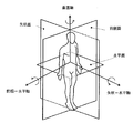
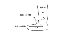
- FIG. 1 is a diagram illustrating directions of respective axes with respect to a measurement target person. Description of this embodiment is performed based on the axis
- the measurement subject is, for example, a patient or a care recipient.
- the frontal face is an arbitrary plane that divides the measurement subject's body into the ventral and dorsal sides.
- the horizontal plane is a plane perpendicular to the direction of gravity.
- the sagittal plane is a plane parallel to the plane that passes through the middle of the measurement subject's body and divides the body into left and right.
- the forehead-horizontal axis is the axis perpendicular to the sagittal plane.
- the sagittal-horizontal axis is the axis orthogonal to the frontal plane.
- the vertical axis is an axis orthogonal to the horizontal plane.
- the origin where the axes intersect is near the center of the body, but the position of the origin is not limited to the position shown in FIG.
- the position of the origin is near the foot.
- the motion data in the rotation direction about the forehead-horizontal axis is X ′ (t).
- the operation data in the rotation direction around the vertical axis is Y ′ (t).
- the motion data in the direction of rotation about the sagittal-horizontal axis is taken as Z '(t).
- operation data in this embodiment indicates an angular velocity per unit time in the rotation direction around each axis.
- direction of operation data when the direction of operation data is not distinguished, it is simply described as operation data.
- the motion data may be data (for example, speed) other than the angular velocity.
- FIG. 2 shows an example of the overall configuration of the system of the embodiment.
- the information processing apparatus 1 is connected to a plurality of relay apparatuses 3 via a network 2.
- the relay device 3 is connected to a plurality of sensors 4.
- One relay device 3 and one sensor 4 may be provided.
- the information processing apparatus 1 acquires data indicating the operation measured by the sensor 4 (hereinafter referred to as operation data) via the network 2 and the relay device 3.
- the information processing apparatus 1 is installed in a hospital, for example.
- the information processing apparatus 1 is an example of a computer.
- the network 2 is, for example, a wide area communication network, and is used for communication between the information processing apparatus 1 and the relay apparatus 3.
- the relay device 3 is installed, for example, at a patient's home or a nursing facility.
- the relay device 3 relays communication between the network 2 and the sensor 4.
- the sensor 4 is, for example, a motion sensor that measures movement, and is attached to a measurement subject's hand or foot.
- the sensor 4 is an inertial sensor such as a gyro sensor that measures angular velocity or an acceleration sensor, for example.
- the sensor 4 may include a plurality of types of sensors.
- the system of this embodiment is not limited to the configuration shown in FIG.
- the system of the embodiment may not include the relay device 3, for example.
- the information processing apparatus 1 may acquire operation data from the sensor 4 via the network 2.
- system may include a device (for example, a server) that receives operation data from the sensor 4 and transmits the received operation data to the relay device 3.
- a device for example, a server
- the information processing apparatus 1 of the embodiment quantifies the operation using an algorithm corresponding to a specific type of operation, assuming that the sensor 4 is mounted at a specific position of the measurement target person.
- the motion type when the motion type is walking, the stepping, landing, takeoff speed, timing, etc. can be quantified by measuring the forehead during walking and the rotational speed in the horizontal axis direction.
- the speed, timing, posture change, etc. when tilting forward can be quantified by measuring the forehead at the time of standing up—the rotational speed and acceleration change in the horizontal axis direction. .
- the quantification accuracy of the operation is lowered.
- the mounting position of the sensor 4 may be deviated from the assumed position due to the movement of the measurement subject wearing the sensor 4. Also in this case, the quantification accuracy of the operation is lowered.
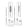
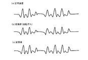
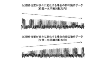
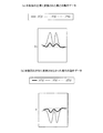
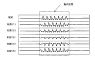
- FIG. 3 shows an example of motion data during walking.
- FIG. 3A shows motion data in the representative direction during walking when the sensor 4 is worn at the normal position of the measurement subject's leg.
- FIG. 3B shows operation data in the representative direction when the sensor 4 is not mounted at the normal position.
- the representative direction is the rotation direction of one of the axes shown in FIG.
- the representative direction indicates a direction in which the motion feature amount of the motion data is equal to or greater than a predetermined reference (first reference) when motion data for a plurality of directions is detected.
- the first reference may be set arbitrarily.
- the number of representative directions is not limited to one and may be two or more.
- the motion feature amount used for specifying the representative direction is, for example, the value of the time change amount of the motion data.
- the motion feature amount used for specifying the representative direction may be, for example, an absolute value, a peak value, or an area of the peak section of the time change amount.
- the representative direction is usually the forehead-horizontal rotation direction.
- the angular velocity of the forehead-horizontal axis is lower than when the sensor 4 is mounted normally. Therefore, in the example shown in FIG. 3, the angular velocity is lower in the operation data in FIG. 3B than in the operation data in FIG.
- the operation itself of the measurement subject wearing the sensor 4 does not change.
- the measurement subject regardless of whether or not the sensor 4 is mounted at a normal position, the measurement subject usually moves forward while rotating the leg during walking. In addition, the measurement subject turns the body while rotating the leg when changing the direction. Therefore, in the case of walking, there is a characteristic that the amount of movement in the rotational direction of the forehead-horizontal axis becomes large.
- the operation amount is, for example, the total value (integral value) of the absolute value of the output value of the sensor 4 in a predetermined section.
- FIG. 4 is a diagram illustrating an example of the information processing apparatus according to the first embodiment.
- the information processing apparatus 1 includes a first storage unit 10, a first communication unit 11, an extraction unit 12, a mixing degree determination unit 13, a specification unit 14, a determination unit 15, a conversion unit 16, and a calculation unit 17. Including.
- the first storage unit 10 includes an action extraction algorithm DataBase (DB) 10a, a determination index DB 10b, a state conversion amount DB 10c, and a feature amount DB 10d.
- DB DataBase
- the first communication unit 11 receives operation data related to the operation transmitted from the sensor 4.
- the extraction unit 12 acquires the operation data from the sensor 4 via the first communication unit 11 and extracts the operation data of the section in which the operation feature amount of the operation data is equal to or greater than the threshold value, thereby detecting the detection target of the operation data. Data on the section indicating the operation is extracted.
- the mixing degree determination unit 13 determines the mixing degree indicating the number of representative directions of movement based on the movement data.
- the degree-of-mixing determination unit 13 determines the degree of mixing based on, for example, variation in motion data in each of three-dimensional directions.
- the identifying unit 14 identifies one or more motion directions (representative directions) in which the motion feature amount (first motion feature amount) is equal to or greater than the first reference based on the motion data. It is preferable that the specifying unit 14 specifies one or a plurality of representative directions in which the motion feature amount is maximized. For example, the specifying unit 14 specifies the same number of representative directions as the degree of mixing based on the size of the motion feature amount in each direction of the data obtained by rotationally converting the motion data.
- the determining unit 15 determines a parameter used for conversion of motion data based on the motion feature amount (second motion feature amount) in the representative direction identified by the identifying unit 14.
- the determination unit 15 uses, for example, the identified representative direction to convert the motion data so that the motion feature amount after the conversion in the representative direction identified by the identifying unit 14 is equal to or greater than a predetermined reference (second reference). Determine the parameters used. For example, it is preferable that the determination unit 15 determines a parameter used for conversion of motion data so that the motion feature amount is maximized.
- the conversion unit 16 converts the operation data using the parameters determined by the determination unit 15.
- the calculation unit 17 specifies an operation type based on the operation data converted by the conversion unit 16, and calculates (quantifies) the feature amount of the operation.
- FIG. 5 is a diagram illustrating an example of the sensor 4.
- the sensor 4 includes a second communication unit 41, an operation measurement unit 42, and a second storage unit 45.
- the second storage unit 45 includes an operation information DB 45a.
- the second communication unit 41 transmits operation data to the information processing apparatus 1.
- the motion measurement unit 42 measures the motion and stores motion data indicating the motion in the motion information DB 45a.
- the motion information DB 45a stores motion data generated by the motion measurement unit 42.
- the senor 4 temporarily stores operation data in the operation information DB 45a and periodically transmits the operation data to the information processing device 1 via the relay device 3 and the network 2.
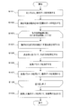
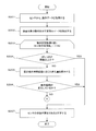
- FIG. 6 is a flowchart illustrating an example of a processing flow according to the first embodiment.
- the first communication unit 11 receives operation data indicating the operation measured by the sensor 4 (step S101).
- the extraction unit 12 extracts data of a motion section indicating a motion to be detected from the received motion data (Step S102).
- the extraction unit 12 extracts the operation interval from the data of the operation type designated in advance from the operation extraction algorithm DB 10a before extracting the data in the interval. Get the algorithm. In the present embodiment, it is assumed that the operation type “walking” has been designated by the user in advance.
- the extraction unit 12 calculates, for example, the motion feature amount of motion data in each direction for each predetermined section, and extracts data in a section where the motion feature amount exceeds a threshold (extraction threshold) included in the algorithm.
- the motion feature amount used in step S102 is, for example, a combined value, maximum value, minimum value, or average value of motion data in each direction.
- the synthesized value of the operation data is expressed as the following formula (1), for example.
- X (t), Y (t), and Z (t) indicate the amount of motion in each direction of motion data.
- S (t) represents a combined value of X (t), Y (t), and Z (t).
- the extraction unit 12 may extract, for example, a section where the variance value, period, or peak value of the motion feature amount of the motion data in each direction exceeds the extraction threshold included in the algorithm.
- the algorithm may include a specific operation pattern, for example.
- the extraction part 12 may compare the acquired operation
- the extraction unit 12 is the data of the section in which the motion feature value or the variance value, period, or peak value of the motion feature value exceeds the extraction threshold value that does not depend on the motion type. May be extracted.
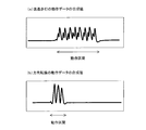
- FIG. 7 is a diagram showing an example of extraction of motion sections.
- FIG. 7A shows a composite value of the motion data of the straight progress row.
- FIG. 7B shows a synthesized value of the direction change motion data.
- a section (motion section) in which it is determined that the target motion has been performed is specified by the extraction unit 12.
- the information processing apparatus 1 starts the iterative process for each motion section extracted in step S102 (step S103).
- the degree-of-mixing determination unit 13 determines the degree of mixing indicating the number of movements in the representative direction for the movement section i (step S104). For example, the mixing degree determination unit 13 acquires a determination index corresponding to the target operation type from the determination index DB 10b including the determination index of the mixing degree, and determines the mixing degree based on the determination index. The degree-of-mixing determination unit 13 determines the degree of mixing based on variations in motion data in each of the three-dimensional directions by using, for example, principal component analysis.
- the degree-of-mixing determination unit 13 may perform principal component analysis on the motion data of the target section, for example, and calculate the cumulative contribution ratio of the generated axis.
- the degree-of-mixing determination unit 13 uses, as the degree of mixing, the smallest number of axes among the number of axes whose cumulative contribution ratio is equal to or greater than a predetermined threshold (cumulative contribution ratio threshold) (for example, 0.9).
- the cumulative contribution rate threshold is included in the determination index stored in the determination index DB 10b.
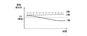
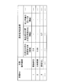
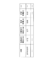
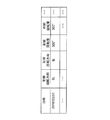
- FIG. 8 is a diagram illustrating an example of the determination result of the degree of mixing.
- the example (first example) shown in FIG. 8A shows the number of axes created by principal component analysis and the cumulative contribution rate for the straight forward operation.
- the cumulative contribution rate exceeds the cumulative contribution rate threshold (0.9) in all the numbers of axes. Therefore, the mixing degree determination unit 13 uses “1”, which is the smallest number of axes among the number of axes whose cumulative contribution ratio exceeds the cumulative contribution ratio threshold, as the mixing degree.
- the amount of movement in the rotation direction of the forehead-horizontal axis is large, and the rotation direction of the forehead-horizontal axis is the representative direction.
- the amount of movement in the sagittal-horizontal axis rotation direction and the vertical axis rotation direction is small. That is, in the principal component analysis, the contribution ratio and variation in the forehead-horizontal axis rotation direction are large, and the sagittal-horizontal axis rotation direction and the vertical axis rotation direction contribution ratio and variation are small.
- the degree (number of representative directions) is “1”.
- the example (second example) shown in FIG. 8B shows the number of axes created by principal component analysis and the cumulative contribution rate for the operation data when the direction is changed.
- the cumulative contribution rate exceeds the cumulative contribution rate threshold value (0.9) when the number of axes is 2 and 3. Therefore, the mixing degree determination unit 13 uses “2”, which is the smallest number of axes among the number of axes whose accumulated contribution rate exceeds the accumulated contribution rate threshold, as the degree of mixing.
- the leg rotates while moving the leg forward, so the amount of movement in the forehead-horizontal axis rotation direction and the vertical axis rotation direction is large, and the forehead-horizontal axis rotation direction and the vertical axis rotation direction are large.
- the rotation direction becomes the representative direction.
- the amount of movement in the rotational direction of the sagittal-horizontal axis is small. That is, in the principal component analysis, the contribution ratio and variation between the forehead-horizontal axis rotation direction and the vertical axis rotation direction are large, and the sagittal-horizontal axis rotation direction contribution ratio and variation are small.
- the degree (number of representative directions) is “2”.
- the example (third example) shown in FIG. 8C shows the number of axes created by principal component analysis and the cumulative contribution rate for the operation data when moving up and down on a spiral staircase. .
- the mixing degree determination unit 13 uses “3”, which is the smallest number of axes among the number of axes whose cumulative contribution ratio exceeds the cumulative contribution ratio threshold, as the mixing degree.
- the specifying unit 14 specifies a representative direction in which the motion feature amount is equal to or greater than the first reference based on the degree of mixing (step S105).
- the specifying unit 14 may specify a representative direction in which the rank of the motion feature amount of the motion data is within a predetermined rank among the plurality of directions.
- the first reference may be a predetermined threshold value (first threshold value), for example. That is, the specifying unit 14 specifies a direction having a larger motion feature amount among a plurality of directions as a representative direction.
- the first reference can be set in advance.
- step S105 for example, if the degree of mixing is 1, the specifying unit 14 specifies one direction in which the motion feature amount of motion data is the maximum among the plurality of directions as the representative direction. For example, if the degree of mixing is 2, the specifying unit 14 specifies, as the representative direction, two directions in which the motion feature amount is maximum among the sum of the motion feature amounts in the two directions. For example, if the degree of mixing is 3, the specifying unit 14 sets all three directions as representative directions.
- the specifying unit 14 may specify the representative direction according to the operation type when the operation type is set in advance. For example, when the operation type is set to the straight line, the specifying unit 14 specifies that the rotation direction of the forehead-horizontal axis is the representative direction. Further, for example, when the operation type is set to change direction, the specifying unit 14 specifies that the forehead-horizontal axis rotation direction and the vertical axis rotation direction are the representative directions. In addition, for example, when the operation type is set to move up and down a spiral staircase, the specifying unit 14 specifies that all directions are representative directions.
- the determining unit 15 determines a parameter (conversion parameter) used for conversion of motion data so that the motion feature amount in the representative direction is equal to or greater than the second reference (for example, maximum), for example (step S106).
- the determining unit 15 determines a plurality of conversion parameter candidates, for example. Then, the determination unit 15 converts the motion data using the determined conversion parameter candidates, and ranks the conversion parameters used for the converted motion data in descending order of the motion feature amount in the representative direction. Then, the determination unit 15 may determine, for example, a conversion parameter whose rank is within a predetermined rank as a parameter used for conversion.
- the second reference may be a predetermined threshold (second threshold), for example. That is, the determination unit 15 determines the conversion parameter so that the motion feature amount in the representative direction becomes larger.
- the second reference can be set in advance.
- the motion feature amount used in step S106 is, for example, the value of the time change amount of the motion data, or the absolute value, the peak value, or the peak section area of the time change amount value.
- the converted operation data is represented by X ′ (t), Y ′ (t), and Z ′ (t) shown in equations (2) to (4).
- the specifying unit 14 specifies that X ′ (t) is motion data in the representative direction when the maximum value of E 11 is the largest among the maximum values of the evaluation functions E 11 to E 13 .
- the determination unit 15 determines a conversion parameter for which E 11 is equal to or greater than the second reference (for example, maximum) as a parameter used for conversion.
- the specifying unit 14 determines that Y ′ (t) is motion data in the representative direction when the maximum value of E 12 is the largest among the maximum values of the evaluation functions E 11 to E 13 .
- the specifying unit 14 specifies that Z ′ (t) is motion data in the representative direction when the maximum value of E 13 is the largest among the maximum values of the evaluation functions E 11 to E 13 .
- the specifying unit 14 determines that X ′ (t) and Y ′ (t) are motion data in the representative direction when the maximum value of E 21 is the largest among the maximum values of the evaluation functions E 21 to E 23. Identify. In this case, the determination unit 15 determines a conversion parameter for which E 21 is equal to or greater than the second reference (for example, maximum) as a parameter used for conversion.
- the second reference for example, maximum
- the specifying unit 14 determines that X ′ (t) and Z ′ (t) are motion data in the representative direction when the maximum value of E 22 is the largest among the maximum values of the evaluation functions E 21 to E 23. Identify. In that case, the determination unit 15, E 22 is a second reference above (e.g., maximum) are determined as parameters used for conversion parameters that are conversion.
- the specifying unit 14 specifies that Y ′ (t) and Z ′ (t) are motion data in the representative direction when the maximum value of E 23 is the largest among the maximum values of E 21 to E 23. .
- Determining unit 15, in which case, E 23 is a second reference above (e.g., maximum) are determined as parameters used for conversion parameters that are conversion.
- specifying section 14 for example, if the degree of mixing is 3, the evaluation value E 3 shown in the following (11), is calculated for a plurality of conversion parameters.
- the specifying unit 14 specifies that X ′ (t), Y ′ (t), and Z ′ (t) are motion data in the representative direction.
- Determining unit 15, in which case, E 3 is the second reference above (e.g., maximum) are determined as parameters used for conversion parameters that are conversion.
- the determination unit 15 converts the parameters for each operation section extracted by the extraction unit 12.
- the determination unit 15 may estimate a conversion parameter for each operation type. For example, the determination unit 15 may determine a parameter for which the second motion feature amount in the identified motion direction is equal to or greater than the second reference for each period (section) determined based on the motion type.
- the motion type is, for example, walking or turning, and the motion pattern or motion detection algorithm for each motion type and its parameters are stored in the first storage unit 10 in advance. Then, the determination unit 15 may determine the operation type based on matching with the stored operation pattern, or may determine using an operation detection algorithm.
- the determination unit 15 may determine a conversion parameter for each operation having a common or similar degree of mixing.
- the determination unit 15 may determine the parameter for which the motion feature amount in the identified motion direction is greater than or equal to the second reference for each period (section) determined based on the degree of mixing.
- the target operation data may include a plurality of operation sections.
- the determination unit 15 may determine, for example, a parameter for which the value obtained by adding or averaging evaluation functions in a plurality of sections is equal to or greater than a predetermined reference (for example, maximum) as a parameter used for conversion.
- the determination unit 15 may determine a conversion parameter in which the motion feature amount in the set representative direction is equal to or greater than the second reference (for example, maximum). For example, when the operation is a straight line, since it can be estimated that the representative direction is the forehead-horizontal axis rotation direction, it is preset that the representative direction is the forehead-horizontal axis rotation direction.
- the determination unit 15 may determine, for example, a conversion parameter in which the motion feature amount in the set representative direction is equal to or greater than a predetermined reference (for example, maximum).
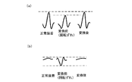
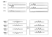
- FIG. 9 is a diagram showing an example of motion data before and after motion conversion according to the number of representative directions.
- the solid lines indicate the operation data X ′ (t), Y ′ (t), Z ′ (t) after conversion, and the dotted lines indicate the operation data X (t), Y (t), Z ( t).
- FIG. 9A shows an example of motion conversion when the representative direction is one direction and X ′ (t) is the representative direction.
- X (t) is converted to increase
- Y (t) and Z (t) are converted to decrease.
- FIG. 9B shows an example of operation conversion when the representative direction is two directions and X ′ (t) and Y ′ (t) are representative directions.
- X (t) and Y (t) are converted so as to increase, and Z (t) is converted so as to decrease.
- FIG. 9C shows an example of operation conversion when the representative directions are three directions and X ′ (t), Y ′ (t), and Z ′ (t) are the representative directions.
- X (t), Y (t), and Z (t) are converted to increase.
- the conversion unit 16 may convert the operation data using the known conversion parameter. Alternatively, the conversion unit 16 may select one by comparing the known conversion parameter with the determined conversion parameter.
- the conversion unit 16 may select a conversion parameter from conversion parameters calculated in the past based on the mounting position.
- the conversion part 16 may select a conversion parameter from the conversion parameter calculated in the past based on the mounting position of the sensor 4 assumed when the operation
- step S108 when the information processing apparatus 1 completes the processes of steps S104 to S107 for all the operation sections, the information processing apparatus 1 ends the repetition process (step S108).
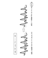
- FIG. 10 is a diagram showing an example of motion data before and after motion conversion.
- 10A to 10C show operation data in the representative direction among the operation data in the three directions including one representative direction.
- FIG. 10A shows operation data when the sensor 4 is mounted at the normal position.
- FIG. 10B shows operation data when the sensor 4 is mounted at a position that is not normal (a position that is rotationally displaced).
- FIG. 10C shows operation data obtained by converting the operation data shown in FIG.
- the operation amount in the operation data in the representative direction is smaller than the operation data in FIG.
- the data shown in FIG. 10C has a larger operation amount than the operation data shown in FIG. 10B, and is close to the operation data shown in FIG. This is because the data shown in FIG. 10C is converted using the conversion parameter that maximizes the motion feature amount in the representative direction after conversion.
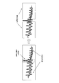
- FIG. 11 is a diagram showing a comparative example of motion data before and after motion conversion.
- FIG. 11A shows a part of the operation data in the representative direction.
- FIG. 11A shows operation data in a representative direction when the sensor 4 is mounted at a normal position, and representative directions before and after conversion when the sensor 4 is mounted at an abnormal position (a rotationally shifted position). Operation data.
- the motion data in the representative direction after conversion is close to the motion data in the representative direction when the sensor 4 is mounted at the normal position.
- FIG. 11B shows a part of operation data other than the representative direction.
- FIG. 11B shows operation data in a direction other than the representative direction when the sensor 4 is mounted at a normal position, and representative before and after conversion when the sensor 4 is mounted at an abnormal position (rotation shifted position). Operation data other than directions are shown.
- the operation data other than the representative direction may have a larger amount of motion when the sensor 4 is mounted at an abnormal position than when the sensor 4 is mounted at a normal position.
- the operation data after the conversion is data close to the operation data when mounted at a normal position.
- the calculation unit 17 calculates a feature amount using the converted motion data (step S109).
- the calculation unit 17 may specify a motion type (for example, walking, direction change, etc.) using the converted motion data.
- the calculation unit 17 may specify the operation type by comparing the converted operation data with a pattern of each operation type stored in advance. When the operation type is already set, the calculation unit 17 may use the operation type for quantification.
- the calculation unit 17 calculates (quantifies) feature amounts such as walking speed and stride. For example, when the operation type is direction change, the calculation unit 17 calculates a feature amount such as a rotation direction and a rotation amount (angle).
- the information processing apparatus 1 determines the conversion parameter in which the motion characteristic amount in the representative direction after the conversion is equal to or greater than a predetermined reference (for example, maximum), and converts the motion data. Then, as shown in FIGS. 10 and 11, the motion feature amount in the representative direction after the conversion increases, so that motion data close to the motion data when mounted in the normal position can be obtained.
- a predetermined reference for example, maximum
- the information processing apparatus 1 can grasp changes in the state (mounting position) and abnormalities of the sensor 4 by accumulating and visualizing conversion parameters, for example.
- the determined conversion parameter can also be used for determining the operation direction of a motion assist device such as a powered suit.
- a large-scale monitoring device used in a hospital to know the state of a patient (measurement target person) is a patient from the viewpoint of securing installation space, introduction cost, and skill in operation. It is not easy to install at home or care facility.
- the state of the measurement subject can be grasped using a small device such as a gyro sensor, for example, so that the operation of the measurement subject can be quantified easily and inexpensively. be able to.
- FIG. 12 is a diagram illustrating an example of an information processing apparatus according to the second embodiment.
- the information processing apparatus 1 according to the second embodiment includes a first abnormality determination unit 18 and a second abnormality determination unit 19 in addition to the configuration included in the information processing apparatus 1 according to the first embodiment.
- 1st abnormality determination part 18 determines the state abnormality of the sensor 4 based on the dispersion
- 2nd abnormality determination part 19 determines the state abnormality of the sensor 4 based on the change according to the time passage of a mixing degree.
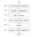
- FIGS. 13 and 14 are flowcharts illustrating an example of the flow of the information processing apparatus according to the second embodiment.
- the flowcharts shown in FIGS. 13 and 14 include steps S204 to S207 in addition to the processes included in the flowchart of the first embodiment shown in FIG.
- Steps S201 to S203 in FIG. 13 and S208 to S213 in FIG. 14 are the same as the processes in steps S101 to S109 in FIG.
- the first communication unit 11 receives operation data indicating the operation measured by the sensor 4 (step S201).
- the extraction unit 12 extracts data of a section indicating the measurement target operation from the received operation data (step S202).
- the first abnormality determination unit 18 determines whether or not the variation in the motion data in the representative direction in the motion section i is equal to or greater than a threshold (first abnormality determination threshold) (step S204). For example, the first abnormality determination unit 18 determines whether the maximum value of the motion amount in the representative direction exceeds the first abnormality determination threshold value in the target motion section. Alternatively, the first abnormality determination unit 18 calculates the difference between the statistical value (maximum value, average value, etc.) of the motion amount in a certain motion section from the statistical value of the motion amount in the previous motion section. You may determine whether it is more than a 1st abnormality determination threshold value.
- the first abnormality determination unit 18 determines that the state of the sensor 4 is abnormal (step S207). Then, the information processing apparatus 1 ends the process.
- the information processing apparatus 1 ends the process when it is determined to be abnormal.
- FIG. 15 shows an example of motion data during walking when the sensor is fixed and when the sensor is not fixed.
- FIG. 15A shows motion data during walking when the sensor is fixed.
- FIG. 15B shows motion data during walking when the sensor is not fixed.
- the first abnormality determining unit 18 determines that the state of the sensor is abnormal.
- the second abnormality determination unit 19 calculates the amount of change according to the elapsed time of the degree of mixing in the extracted motion section (step S205). For example, the second abnormality determination unit 19 calculates the degree of mixing for the cumulative value of the motion data within a predetermined time width in the motion section i, and calculates the degree of mixing by changing (for example, increasing) the time width and the cumulative value. By repeating the process, the amount of change corresponding to the elapsed time of the degree of mixing is calculated.
- step S206 the second abnormality determination unit 19 determines that the operation type has changed, for example, when the degree of mixing has changed during one operation section.
- the second abnormality determining unit 19 determines that the state of the sensor 4 is abnormal (step S207) when it is determined that the operation type has changed during one operation interval (YES in step S206). Then, the information processing apparatus 1 ends the process.
- the second abnormality determination unit 19 it may be determined that the state is abnormal.
- the second abnormality determination unit 19 compares a conversion parameter of a specific operation section with a known conversion parameter, and determines that the state of the sensor 4 is abnormal when the difference is equal to or greater than a second abnormality determination threshold value. May be.
- FIG. 16 is a diagram showing leg motion data when the mounting position gradually changes.
- FIG. 16A shows leg motion data in the forehead-horizontal axis direction when the mounting position gradually changes.
- the operation amount gradually decreases.
- FIG. 16B shows leg motion data in the sagittal-horizontal axis direction when the mounting position gradually changes.
- the operation amount gradually increases.
- the sensor 4 is mounted normally. It is assumed that the position is gradually shifted from the position.
- FIG. 17 is a diagram showing a change in the degree of mixing when the mounting position gradually changes. As shown in FIG. 17, since the cumulative contribution rate exceeds the cumulative contribution rate threshold value in each axis at the beginning of the motion section, the degree of mixture is 1, but the cumulative contribution rate of one axis decreases with time and the cumulative contribution rate Below threshold. Therefore, the degree of mixing changes from 1 to 2.
- the second abnormality determination unit 19 determines that the operation type has changed during one operation interval, and determines that the state of the sensor 4 is abnormal.
- the mixing degree determination unit 13 determines a mixing degree indicating the number of representative directions of movement for the movement section i (step S208). Based on the degree of mixing, the specifying unit 14 specifies a representative direction in which the motion feature amount is the first reference (for example, maximum) (step S209). The determination unit 15 determines a parameter (conversion parameter) used for conversion of motion data so that the motion feature amount in the representative direction is equal to or greater than the second reference (for example, maximum) (step S210).
- the conversion unit 16 converts the operation data using the conversion parameter determined by the determination unit 15 (step S211).
- the information processing apparatus 1 ends the repetitive processing when the processing of steps S204 to S211 is completed for all the motion sections (step S212).
- the calculation unit 17 calculates a feature amount using the converted motion data (step S213).
- the information processing apparatus 1 determines whether the state of the sensor 4 is abnormal. If the information processing apparatus 1 is abnormal, the information processing apparatus 1 ends the process, and thus does not convert abnormal operation data. Therefore, it is possible to avoid quantification based on abnormal operation data.
- Example of information processing apparatus An information processing apparatus according to a third embodiment will be described with reference to the drawings.
- the information processing apparatus according to the third embodiment is assumed to have the same configuration and functions as those of the information processing apparatus according to the first embodiment or the second embodiment, which are not particularly described. Since the configuration of the information processing apparatus according to the third embodiment is the same as the configuration of the information processing apparatus according to the first embodiment or the second embodiment, description thereof is omitted.
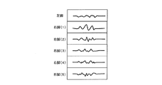
- FIG. 18 is a diagram illustrating an example of motion data when a motion of walking backward is included during walking.
- FIG. 18 shows motion data in the representative direction among the motion data of the left and right legs.
- the sign of the motion data is reversed.
- the conversion result may not be normal.
- the determination unit 15 determines the conversion parameter based on the motion feature amount that does not depend on the sign of the motion data. For example, the determination unit 15 determines the conversion parameter such that the motion feature amount that does not depend on the sign in the representative direction is equal to or greater than the second reference (for example, maximum).
- the motion feature quantity that does not depend on positive or negative is a motion feature quantity whose value is positive, such as the absolute value of the peak of the motion data, the area of the peak section, or the like.
- the determination unit 15 determines the conversion parameter so that any evaluation function of the equations (5) to (11) is equal to or greater than a predetermined reference (for example, maximum). Good. Since equations (5) to (11) are evaluation functions based on the absolute values of the motion data X ′ (t), Y ′ (t), and Z ′ (t), they are positive regardless of whether the motion data is positive or negative. This is because it becomes the data.
- a predetermined reference for example, maximum
- the conversion unit 16 uses the conversion parameter calculated based on the motion feature amount that does not depend on the sign of the motion data, so that even if the motion data of the forward walking and the backward walking are mixed, appropriate conversion is performed. Later data can be obtained.
- FIG. 19 is a diagram showing operation data before and after conversion when the conversion parameter is a local solution.
- ⁇ is a section number assigned to each operation section.
- the determination unit 15 does not employ conversion parameters that greatly change in a short time.
- the determination unit 15 calculates a conversion parameter using an evaluation function to which a constraint is added as in the following Expression (12).
- Expression (12) is an example in which a restriction is added to Expression (5).
- ⁇ ⁇ + 1 is a conversion parameter for the first operation interval
- ⁇ ⁇ is a conversion parameter for one or a plurality of second operation intervals calculated in advance from the first operation interval.
- ⁇ is a parameter indicating how much difference between the conversion parameter of the target motion section and the conversion parameter of the previous motion section is allowed.
- the determination unit 15 determines the difference between the conversion parameter in the first operation section ( ⁇ + 1) and the conversion parameter in the second operation section ( ⁇ ) calculated in advance a predetermined time ( For example, a value obtained by multiplying a predetermined parameter by (Euclidean distance) is subtracted.
- the determination unit 15 substitutes a plurality of conversion parameter candidates for ⁇ ⁇ + 1 and determines the conversion parameter so that the evaluation function shown in Expression (12) becomes the largest.
- a difference for example, Euclidean distance
- the evaluation function becomes smaller depending on whether or not, the possibility that the conversion parameter when the difference (for example, the Euclidean distance) is large is used for the conversion becomes low. That is, when the conversion parameter changes greatly in a short time, the conversion parameter is less likely to be used for conversion.
- Expression (12) is an evaluation function corresponding to Expression (5), but the determination unit 15 adds the same constraint (the fourth term of Expression (12)) to Expressions (6) to (11). Thus, it may be used to determine conversion parameters.
- the second operation section is, for example, the operation section immediately before the first operation section.
- the second operation section may be an operation section after the first operation section, for example.
- the determination unit 15 may apply a Kalman filter or a state space model, for example, and estimate a conversion parameter with a small amount of change in a short time using the operation data and the conversion parameter of the operation interval before the target operation interval. .
- the determination unit 15 calculates the difference between the conversion parameter candidate in the first operation interval in the operation data and the conversion parameter determined for the second operation interval a predetermined time before the first operation interval. . Then, the determination unit 15 determines the conversion parameter in the first operation section from the conversion parameter candidates based on the difference. Therefore, for example, the information processing apparatus 1 can determine an appropriate conversion parameter even if the acquired operation data includes abnormal operation data.
- FIG. 20 is a diagram showing segmentation of motion data including abnormal motion.
- the tendency of operation data may change significantly in a short time.
- the reason why the tendency of the motion data changes greatly in a short time is, for example, that the measurement subject touches the sensor 4 with his / her hand or the sensor 4 hits an obstacle to receive an impact (for example, the state of the sensor 4 Mounting position) is changed.
- motion data of different sensor states is included in one motion section, an appropriate result may not be obtained when determination of the degree of mixing and parameter conversion are performed for each motion section thereafter.
- the extraction unit 12 separates the operation section into sections before and after the abnormal operation data. For example, when the peak value of the operation data is equal to or greater than the extraction threshold, the extraction unit 12 determines that the operation data is abnormal. Then, the extraction unit 12 outputs the separated operation section to the mixing degree determination unit 13.
- the extraction unit 12 detects a portion indicating abnormal operation in the operation data, and extracts the operation data from a section before the portion indicating the abnormal operation and a section after the portion indicating the abnormal operation. And the separated sections are extracted. By separating the sections, it is possible to suppress the movement data based on a plurality of sensor states from being included in one movement section. And the determination part 15 can determine an appropriate parameter by determining a conversion parameter for every operation
- FIG. 21 is a diagram showing an example of operation data for direction change after conversion in a plurality of operation sections.
- the motion section (1) and the motion section (2) in FIG. 21 are motion sections during the direction change. It is assumed that the representative directions for the direction change are X ′ (t) and Y ′ (t). As shown in FIG. 21, the movement amount of Y ′ (t) is the largest in the movement section (1), but the movement quantity of X ′ (t) is the largest in the movement section (2).
- the direction in which the motion amount is the largest among the representative directions (hereinafter referred to as the dominant axis direction) may be different for each motion section.
- the accuracy may be reduced. Therefore, when the specifying unit 14 specifies two or more representative directions, it is preferable to distinguish which direction is the dominant axis direction.
- the determination unit 15 calculates an operation amount of the operation data before conversion in each representative direction, and determines a direction (dominant axis direction) having the largest operation amount. And the determination part 15 determines the conversion parameter from which the operation
- the determination unit 15 may determine the dominant axis direction according to the motion type. For example, when the motion type is walking, the rotation direction of the forehead-horizontal axis may be determined as the dominant axis direction. In addition, when the same type of operation is repeated a plurality of times, the determination unit 15 determines the direction in which the total operation amount is the largest among the operation data corresponding to the plurality of operations or the most total operation after the conversion. The direction in which the amount increases may be determined as the dominant axis direction.
- the determination unit 15 determines the parameter that maximizes the motion feature amount in the direction with the largest motion amount among the representative directions. Can be suppressed.
- FIG. 22 is a diagram showing operation data after conversion of direction change.
- FIG. 22A shows operation data when converted normally.
- FIG. 22B shows operation data when conversion is not performed normally.
- the right-turning motion data may become negative data by conversion.
- X ′ (t) is operation data in the rotation direction of the forehead-horizontal axis.
- the leg rotates forward regardless of the turning direction, so X ′ (t) is normally positive.
- X ′ (t) is negative data, it can be seen that the operation data is abnormal. That is, for example, if it is known that the motion data is during forward walking, it can be determined whether the motion data after conversion is normal based on the sign of the motion data of X ′ (t).
- the determination unit 15 determines the conversion parameter so that the operation data of X ′ (t) becomes positive, for example, when the type of operation indicates a change of direction.
- the following formula (13) is a formula obtained by removing the absolute value of X ′ (t) in formula (8).
- X ′ (t) is negative by removing the absolute value of the motion data X ′ (t) that is not the rotation direction of the dominant axis among the motion data in a plurality of representative directions.
- a conversion parameter in a certain case is difficult to be adopted as a parameter actually used for conversion. Therefore, the conversion parameter is determined so that the operation data of X ′ (t) is positive.
- the information processing apparatus 1 determines the conversion parameter based on the sign of the motion data in the known direction if one of the plurality of representative directions is known. The possibility that the sign is reversed can be suppressed.
- FIG. 23 is a diagram showing the rotation direction of the legs. Usually, when the operation is straight forward, the rotation direction of the forehead-horizontal axis is the representative direction.
- the specifying unit 14 specifies the representative direction in the process of step S105 or S209. However, motion data in a direction other than the representative direction may be replaced and estimated by motion data conversion processing.
- the sagittal-horizontal axis rotation direction motion data may be output as Y ′ (t), and Z ′ (t ) May be output. Further, motion data in the rotation direction of the vertical axis may be output as Z ′ (t), and may be output as Y ′ (t).
- the determination unit 15 causes the motion data in the direction with the larger motion amount among the motion data in the direction that is not the representative direction to be motion data in the rotation direction of the vertical axis (Y ′ (t) in the present embodiment). Determine the conversion parameters.
- the determination unit 15 may calculate the conversion parameter based on, for example, the following formula (14) obtained by adding a constraint condition to the formula (5).
- Expression (14) it is assumed that the motion data in the rotation direction of the vertical axis is Y ′ (t), and the rotation direction of the sagittal-horizontal axis is Z ′ (t).
- the determination unit 15 may determine the conversion parameter using the magnitude relationship as a constraint.
- the information processing apparatus 1 determines the conversion parameter using the magnitude relationship as a constraint when the magnitude relation of the motion data in directions other than the representative direction is known. It is possible to prevent data from being replaced by conversion.
- FIG. 24 shows operation data from each sensor 4 acquired by the extraction unit 12 in the first embodiment.
- FIG. 24 only operation data in the representative direction is shown, and illustration of operation data in directions other than the representative direction is omitted.
- the operation data are also different.
- FIG. 25 is a diagram illustrating an example of an operation extraction algorithm.
- the extraction unit 12 acquires an algorithm for extracting a previously designated action from the action extraction algorithm DB 10a, and extracts data of a section indicating the action to be detected.
- the motion extraction algorithm is algorithm no. And each parameter used for motion extraction.
- the parameters are, for example, the peak value of the composite value, the peak interval of the composite value, the peak width of the composite value, and the peak gradient of the composite value.
- Each algorithm includes, for example, whether a parameter is necessary ( ⁇ or ⁇ ) and a threshold value for each parameter.
- the motion extraction algorithm may include an extraction method using each parameter.
- the motion extraction algorithm is stored for each motion type, for example.
- the motion extraction algorithm DB 10a applies the algorithm No1 corresponding to the walking motion.
- FIG. 26 is a diagram showing an example of the extracted motion section. As shown in FIG. 26, a portion indicating the operation to be detected is extracted from the operation data.
- the mixing degree determination unit 13 acquires a determination index corresponding to the target action from the determination index DB 10b including the determination index of the mixing degree, and determines the mixing degree based on the determination index.
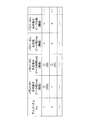
- FIG. 27 is a diagram showing an example of the determination index of the degree of mixing.
- the determination index DB 10b stores therein a determination index definition number, a target action, and a determination index for the degree of mixing in association with each other.
- the determination index of the degree of mixture includes a threshold value of the cumulative contribution ratio of the principal component analysis, a threshold value of the ratio of the independent component analysis, and a threshold value of other values (for example, covariance, standard deviation, etc.) indicating movement data variation .
- the determination index of the degree of mixing is a determination threshold value (for example, a minimum threshold value of the variation size) for evaluating the variation of motion data including a three-dimensional motion direction.
- the mixing degree determination unit 13 uses the smallest number of axes among the number of axes whose value corresponding to the determination index of the motion data is equal to or greater than the threshold value as the mixing degree. In this embodiment, since the target action is a straight line, the determination index of definition No1 is used for determining the degree of mixing. The mixing degree determination unit 13 determines the mixing degree using the determination index of definition No1, and it is assumed that the mixing degree is “1”.
- the specifying unit 14 specifies the representative direction based on the degree of mixing.
- the degree of mixing is “1”
- the specifying unit 14 specifies the direction in which the motion feature amount is the maximum among the motion feature amounts in a plurality of directions as the representative direction.
- the determination unit 15 determines the conversion parameter so that the motion feature amount in the representative direction is maximized.
- FIG. 28 is a diagram illustrating an example of information stored in the state conversion amount DB.
- the determination unit 15 stores the determined conversion parameter in the state conversion amount DB 10c.
- the state conversion amount DB stores the date, the operation start time, the operation end time, and the state conversion amount in association with each other.
- the state conversion amount includes, for example, an X-axis rotation amount ( ⁇ ), a Y-axis rotation amount ( ⁇ ), and a Z-axis rotation amount ( ⁇ ).
- the state conversion amount corresponds to the conversion parameter.
- FIG. 29 is a diagram illustrating an example of operation data before and after conversion.
- X ′ (t) is motion data in the rotation direction of the forehead-horizontal axis
- Y ′ (t) is motion data in the rotation direction of the vertical axis
- Z ′ (t) is an arrow.
- FIG. 29 shows the operation data before and after conversion in the three directions (X ′ (t), Y ′ (t), Z ′ (t)) of the right leg (1) and the right legs (2) to (5).
- the operation amount is increased by the conversion. Further, the amount of movement of Y ′ (t) and Z ′ (t) is reduced by the conversion.
- the motion is walking, and X ′ (t) is the representative direction. Therefore, the motion amount in the representative direction is increased by the conversion, and the motion amount in the direction other than the representative direction is decreased.
- the converted operation data is data close to the operation data when the sensor 4 is mounted at the normal position.
- the calculation unit 17 specifies an operation type using the converted operation data, and quantifies the operation.
- the calculation unit 17 specifies that the converted motion data is walking.
- the calculation unit 17 quantifies the feature amount related to walking based on the converted motion data and stores it in the feature amount DB 10d.
- FIG. 30 is a diagram illustrating an example of motion feature amounts related to walking stored in the feature amount DB. As illustrated in FIG. 30, the motion feature amount related to walking indicates date and time, left leg walking speed, right leg walking speed, left leg stride, and right leg stride.
- the calculation unit 17 stores, for example, the amplitude of the motion data in the feature amount DB 10d as the walking speed. For example, the calculation unit 17 calculates the walking width based on the integral value of the motion data, and stores the walking width in the feature amount DB 10d.
- ⁇ Second embodiment> As a second embodiment, an example of quantifying the characteristics of how to walk while changing direction when the measurement subject wears one sensor 4 on the left leg and five sensors 4 on the right leg will be described. To do. In this embodiment, processing not particularly described is the same as that in the first embodiment.
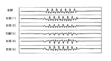
- FIG. 31 shows operation data from each sensor 4 acquired by the extraction unit 12 in the second embodiment.
- FIG. 31 only operation data in the representative direction is shown, and illustration of operation data in directions other than the representative direction is omitted.
- the operation data are also different.
- the extraction unit 12 acquires an algorithm for extracting a predesignated operation from the operation extraction algorithm DB 10a, and extracts data of a section indicating a detection target operation. In the present embodiment, using the algorithm associated with algorithm No. 2 in FIG. 25, the data of the section indicating the operation to be detected is extracted.
- the mixing degree determination unit 13 acquires a determination index corresponding to the target action from the determination index DB 10b including the determination index of the mixing degree, and determines the mixing degree based on the determination index.
- the mixing degree determination unit 13 determines the mixing degree using the mixing degree determination index associated with the definition No. 2 in FIG. In the present embodiment, it is assumed that the mixing degree determination unit 13 determines that the mixing degree is “2”.
- the specifying unit 14 specifies the representative direction based on the degree of mixing.
- the degree of mixing is “2”
- the specifying unit 14 specifies the maximum two directions among the total of the motion feature amounts in the two directions as the representative direction.
- the determination unit 15 determines the conversion parameter so that the motion feature amount in the representative direction is maximized.
- FIG. 32 is a diagram illustrating an example of operation data before and after conversion.
- X ′ (t) is the motion data in the rotation direction of the forehead-horizontal axis
- Y ′ (t) is the motion data in the rotation direction of the vertical axis
- Z ′ (t) is the arrow data.
- FIG. 32 shows the operation data before and after conversion in the three directions (X ′ (t), Y ′ (t), Z ′ (t)) of the right leg (1) and the right legs (2) to (5).
- the calculation unit 17 specifies an operation type using the converted operation data, and quantifies the operation.
- the calculation unit 17 specifies that the converted operation data is a direction change.
- the calculation unit 17 quantifies the feature amount related to the direction change based on the converted motion data, and stores it in the feature amount DB 10d.
- FIG. 33 is a diagram illustrating an example of the motion feature amount related to the direction change stored in the feature amount DB. As shown in FIG. 33, the motion feature amount related to the direction change indicates date and time, left leg rotation direction, right leg rotation direction, left leg rotation amount, and right leg rotation amount.
- the calculation unit 17 determines that the movement direction of the movement data is positive if the movement amount is positive, and if the movement amount is negative, the calculation section 17 stores the rotation direction in the feature amount DB 10d. For example, the calculation unit 17 calculates a rotation amount (rotation angle) based on an integral value within one cycle of the operation data, and stores the rotation amount in the feature amount DB 10d.
- a processor 111 a random access memory (RAM) 112, and a read only memory (ROM) 113 are connected to the bus 100.
- An auxiliary storage device 114, a medium connection unit 115, and a communication interface 116 are connected to the bus 100.
- the processor 111 executes the program expanded in the RAM 112. As a program to be executed, an information processing program for performing processing in the embodiment may be applied.
- the ROM 113 is a non-volatile storage device that stores programs developed in the RAM 112.
- the auxiliary storage device 114 is a storage device that stores various types of information. For example, a hard disk drive or a semiconductor memory may be applied to the auxiliary storage device 114.
- the medium connection unit 115 is provided so as to be connectable to the portable recording medium 118.
- a portable recording medium 118 a portable memory, an optical disc (for example, Compact Disc (CD) or Digital Versatile Disc (DVD)), a semiconductor memory, or the like may be applied.
- An information processing program for performing the processing of the embodiment may be recorded on the portable recording medium 118.
- the first storage unit 10 shown in FIGS. 4 and 12 may be realized by the RAM 112, the auxiliary storage device 114, or the like.
- the first communication unit 11 illustrated in FIGS. 4 and 12 may be realized by the communication interface 116.
- the RAM 112, the ROM 113, the auxiliary storage device 114, and the portable recording medium 118 are all examples of a computer-readable tangible storage medium. These tangible storage media are not temporary media such as signal carriers.
- the present embodiment is not limited to the above-described embodiment, and various configurations or embodiments can be taken without departing from the gist of the present embodiment.
Landscapes
- Health & Medical Sciences (AREA)
- Life Sciences & Earth Sciences (AREA)
- Physics & Mathematics (AREA)
- Engineering & Computer Science (AREA)
- Medical Informatics (AREA)
- Animal Behavior & Ethology (AREA)
- Veterinary Medicine (AREA)
- Biophysics (AREA)
- Pathology (AREA)
- Physiology (AREA)
- Biomedical Technology (AREA)
- Heart & Thoracic Surgery (AREA)
- Public Health (AREA)
- Molecular Biology (AREA)
- Surgery (AREA)
- General Health & Medical Sciences (AREA)
- Oral & Maxillofacial Surgery (AREA)
- Dentistry (AREA)
- Geometry (AREA)
- Artificial Intelligence (AREA)
- Computer Vision & Pattern Recognition (AREA)
- Psychiatry (AREA)
- Signal Processing (AREA)
- Measurement Of The Respiration, Hearing Ability, Form, And Blood Characteristics Of Living Organisms (AREA)
- Hardware Redundancy (AREA)
- Debugging And Monitoring (AREA)
Abstract
情報処理システムは、動作を測定するセンサと、前記センサから前記動作に関する動作データを受信する情報処理装置と、を備え、前記情報処理装置は、前記動作データに基づいて、第1の動作特徴量が第1基準以上となる1または複数の動作方向を特定する特定部と、前記特定された方向を用いて、変換後の前記方向での第2の動作特徴量が第2基準以上となる、前記動作データの変換に用いられるパラメータを決定する決定部と、を含む。
Description
本発明は、情報処理システム、情報処理装置、情報処理方法および情報処理プログラムに関する。
例えば、病院内のみで行われていた患者に対するケアが、患者宅や各地域の介護施設等で行われることが増加している。また、患者に対するケアを行う担当者は、患者が自宅や介護施設等にいる場合でも、患者の状態やその経過(変化)を把握できることが求められている。
関連する技術として、体参照システムと方向検知ユニットに係る参照システムとの間の変換関係を決定することにより体に関してデバイスの相対的な方向を決定する技術が提案されている(例えば、特許文献1を参照)。行動検知装置の中心点を中心とした回転角の検出を行い、検出結果に基づいて加速度データの補正を行う技術が提案されている(例えば、特許文献2を参照)。加速度ベクトルデータから計算される前方向のベクトルの大きさの総和と後方向のベクトルの大きさの総和の差異に基づいて歩様バランスを判定する技術が提案されている(例えば、特許文献3を参照)。
また、関連する技術として、ジャイロセンサを用いて歩行検知し、歩行速度や歩幅などを定量化する技術が提案されている(例えば、非特許文献1を参照)。また、加速度センサ、ジャイロセンサを用いて着席、起立を検知する技術が提案されている(例えば、非特許文献2を参照)。
Fraccaro et al., "Real-world Gyroscope-based Gait Event Detection and Gait Feature Extraction". eTELEMED 2014
Van Lummel et al., "Automated approach for quantifying the repeated sit-to-stand using one body fixed sensor in young and older adults". Gait & Posture. Vol.38, pp.153-156, 2013
例えば、装着型のモーションセンサを用いて計測対象者(例えば、患者)の動作を検知し、検知された動作を定量化することが考えられる。しかし、上記のモーションセンサの装着位置が想定された位置からずれている場合、動作を定量化する精度が低下する。
1つの側面として、本発明は、動作の定量化の精度低下を抑制することを目的とする。
1つの態様では、動作を測定するセンサと、前記センサから前記動作に関する動作データを受信する情報処理装置と、を備え、前記情報処理装置は、前記動作データに基づいて、第1の動作特徴量が第1基準以上となる1または複数の動作方向を特定する特定部と、前記特定された方向を用いて、変換後の前記方向での第2の動作特徴量が第2基準以上となる、前記動作データの変換に用いられるパラメータを決定する決定部と、を含む、ことを特徴とする情報処理システム。
1つの側面によれば、動作の定量化の精度低下を抑制することができる。
以下、図面を参照して、実施形態について説明する。本実施形態の説明に用いる各軸について説明する。図1は、計測対象者を基準とした各軸の方向を示す図である。本実施形態の説明は、図1に示す軸に基づいて行われる。計測対象者は、例えば、患者や介護対象者等である。
前額面は、計測対象者の体を腹側と背側に分割する任意の平面である。水平面は、重力方向に垂直な平面である。矢状面は、計測対象者の体の正中を通り、体を左右に分ける面と平行な面である。
前額-水平軸は、矢状面に対して直交する軸である。矢状-水平軸は、前額面に対して直交する軸である。垂直軸は、水平面に対して直交する軸である。
なお、図1では、各軸が交わる原点は体の中心付近にあるが、原点の位置は図1に示す位置には限られない。例えば、歩行を示す動作データを取得する場合、原点の位置は足元付近となる。
本実施形態の説明において、前額-水平軸を中心とした回転方向の動作データをX’(t)とする。垂直軸を中心とした回転方向の動作データをY’(t)とする。矢状-水平軸を中心とした回転方向の動作データをZ’(t)とする。
なお、本実施形態における動作データは、各軸を中心とした回転方向の単位時間毎の角速度を示す。本実施形態の説明において、動作データの方向を区別しない場合、単に動作データと記載する。動作データは、角速度以外のデータ(例えば、速度)であってもよい。
<実施形態のシステムの全体構成の一例>
図2は、実施形態のシステムの全体構成の一例を示す。図2の例に示されるように、情報処理装置1は、ネットワーク2を介して、複数の中継装置3に接続される。中継装置3は、複数のセンサ4に接続される。中継装置3およびセンサ4は1つであってもよい。
図2は、実施形態のシステムの全体構成の一例を示す。図2の例に示されるように、情報処理装置1は、ネットワーク2を介して、複数の中継装置3に接続される。中継装置3は、複数のセンサ4に接続される。中継装置3およびセンサ4は1つであってもよい。
情報処理装置1は、センサ4が測定した動作を示すデータ(以下、動作データと称する)をネットワーク2、中継装置3、を介して取得する。情報処理装置1は、例えば、病院に設置される。情報処理装置1は、コンピュータの一例である。
ネットワーク2は、例えば、広域通信網であり、情報処理装置1と中継装置3との間の通信に用いられる。
中継装置3は、例えば、患者の自宅や介護施設等に設置される。中継装置3は、ネットワーク2とセンサ4との間の通信を中継する。
センサ4は、例えば、動きを測定するモーションセンサであり、計測対象者の手や足等に装着される。センサ4は、例えば、角速度を測定するジャイロセンサ、または加速度センサ等の慣性センサである。センサ4は、複数の種類のセンサを含んでいてもよい。
本実施形態のシステムは図2に示す構成に限られない。実施形態のシステムは、例えば、中継装置3を含まなくてもよい。その場合、例えば、情報処理装置1がネットワーク2を介して、センサ4から動作データを取得してもよい。
また、本実施形態のシステムは、センサ4から動作データを受信し、受信した動作データを中継装置3に送信する装置(例えば、サーバ)を含んでいてもよい。
実施形態の情報処理装置1は、センサ4が計測対象者の特定の位置に装着されたことを想定し、特定の種類の動作に対応したアルゴリズムを用いて、動作を定量化する。
例えば、動作種類が歩行である場合、歩行中の前額-水平軸方向における回転速度を測定することにより、踏み出し、着地、離地の速度、タイミングなどを定量化することができる。また、動作種類が起立である場合、起立時の前額-水平軸方向における回転速度、加速度変化を測定することにより、前傾する時の速度、タイミング、姿勢変化などを定量化することができる。
しかし、センサ4が特定の位置に装着されたことを想定して動作を定量化する場合、センサ4の装着位置が想定された位置(正常な位置:正常位置)からずれると、動作の定量化精度が低下する場合がある。
例えば、センサ4の初期的な装着位置(初期装着位置)が、想定された位置からずれると、動作の定量化精度が低下する。また、センサ4を装着した計測対象者の動きによって、センサ4の装着位置が想定された位置からずれることもある。この場合も、動作の定量化精度が低下する。
図3は、歩行時の動作データの例である。図3(a)は、センサ4が、計測対象者の脚の正常位置に装着されている場合の歩行時の代表方向の動作データである。図3(b)は、センサ4が正常位置に装着されていない場合の代表方向の動作データである。
なお、代表方向は、図1に示すいずれかの軸の回転方向である。代表方向は、複数方向毎の動作データを検出する場合、動作データの動作特徴量が所定基準(第1基準)以上である方向を示す。第1基準は任意に設定されてよい。
代表方向は1つとは限らず、2つ以上であってもよい。代表方向の特定に用いられる動作特徴量は、例えば、動作データの時間変化量の値である。代表方向の特定に用いられる動作特徴量は、例えば、該時間変化量の、絶対値、ピーク値、またはピーク区間の面積であってもよい。
動作種類が歩行である場合、通常、代表方向は前額-水平軸の回転方向となる。センサ4が正常位置に装着されていない場合、センサ4が正常に装着されている場合と比べて、前額-水平軸の角速度が低くなる。そのため、図3に示す例では、図3(a)の動作データに比べて、図3(b)の動作データの方が、角速度が低い。
一方、センサ4が正常位置に装着されているか否かにかかわらず、センサ4を装着した計測対象者の動作自体は変わらない。例えば、センサ4が正常位置に装着されているか否かにかかわらず、通常、計測対象者は、歩行時は脚を回転させながら前に移動する。また、計測対象者は、方向転換時は脚を回転させながら体を旋回させる。よって、歩行の場合、前額-水平軸の回転方向の動作量が大きくなる特性がある。
動作量は、例えば、センサ4の出力値の、所定区間における絶対値の合計値(積分値)である。
また、例えば、動作種類が歩行であれば前額-水平軸の回転方向への回転が生じるという方向性がある。また、動作が方向転換であれば垂直軸の方向への回転が生じるという特性がある。
<第1の実施形態の情報処理装置の一例>
図4は、第1の実施形態の情報処理装置の一例を示す図である。情報処理装置1は、第1記憶部10と、第1通信部11と、抽出部12と、混合度判定部13と、特定部14と、決定部15と、変換部16と、算出部17とを含む。
図4は、第1の実施形態の情報処理装置の一例を示す図である。情報処理装置1は、第1記憶部10と、第1通信部11と、抽出部12と、混合度判定部13と、特定部14と、決定部15と、変換部16と、算出部17とを含む。
第1記憶部10は、動作抽出アルゴリズムDataBase(DB)10aと、判定指標DB10bと、状態変換量DB10cと、特徴量DB10dとを含む。
第1通信部11は、センサ4から送信された、動作に関する動作データを受信する。
抽出部12は、センサ4から、第1通信部11を介して動作データを取得し、動作データの動作特徴量が閾値以上となる区間の動作データを抽出することにより動作データのうち検出対象の動作を示す区間のデータを抽出する。
抽出部12は、センサ4から、第1通信部11を介して動作データを取得し、動作データの動作特徴量が閾値以上となる区間の動作データを抽出することにより動作データのうち検出対象の動作を示す区間のデータを抽出する。
混合度判定部13は、動作データに基づいて、動作の代表方向の数を示す混合度を判定する。混合度判定部13は、例えば、3次元の各方向における動作データのばらつきに基づいて混合度を判定する。
特定部14は、動作データに基づいて、動作特徴量(第1の動作特徴量)が第1基準以上となる1または複数の動きの方向(代表方向)を特定する。特定部14は、動作特徴量が最大となる1または複数の代表方向を特定することが好ましい。特定部14は、例えば、動作データを回転変換させたデータの各方向の動作特徴量の大きさに基づいて、混合度と同数の代表方向を特定する。
決定部15は、特定部14により特定された代表方向における動作特徴量(第2の動作特徴量)に基づいて、動作データの変換に用いられるパラメータを決定する。決定部15は、例えば、特定された代表方向を用いて、特定部14が特定した代表方向における変換後の動作特徴量が所定基準(第2基準)以上となるように、動作データの変換に用いられるパラメータを決定する。決定部15は、例えば、上記の動作特徴量が最大となるように、動作データの変換に用いられるパラメータを決定することが好ましい。
変換部16は、決定部15により決定されたパラメータを用いて動作データを変換する。
算出部17は、変換部16が変換した動作データに基づいて、動作種類を特定し、動作の特徴量を算出(定量化)する。
<センサの一例>
図5は、センサ4の一例を示す図である。センサ4は、第2通信部41と、動作測定部42と、第2記憶部45とを含む。第2記憶部45は、動作情報DB45aを含む。
図5は、センサ4の一例を示す図である。センサ4は、第2通信部41と、動作測定部42と、第2記憶部45とを含む。第2記憶部45は、動作情報DB45aを含む。
第2通信部41は、情報処理装置1に動作データを送信する。動作測定部42は、動作を測定して、動作を示す動作データを動作情報DB45aに記憶させる。動作情報DB45aは、動作測定部42が生成した動作データを記憶する。
センサ4は、例えば、動作データを一時的に動作情報DB45aに記憶させ、中継装置3、ネットワーク2を介して定期的に情報処理装置1に送信する。
<第1の実施形態の処理の流れの一例>
図6は、第1の実施形態の処理の流れの一例を示すフローチャートである。第1通信部11は、センサ4が測定した動作を示す動作データを受信する(ステップS101)。
図6は、第1の実施形態の処理の流れの一例を示すフローチャートである。第1通信部11は、センサ4が測定した動作を示す動作データを受信する(ステップS101)。
抽出部12は、受信した動作データから検出対象の動作を示す動作区間のデータを抽出する(ステップS102)。予め指定された動作種類が設定されている場合、抽出部12は、上記の区間のデータを抽出する前に、動作抽出アルゴリズムDB10aから、予め指定された動作種類のデータから動作区間を抽出するためのアルゴリズムを取得する。本実施形態では、予め「歩行」という動作種類がユーザから指定されていたとする。
抽出部12は、例えば、各方向の動作データの動作特徴量を所定区間毎に算出し、動作特徴量が上記アルゴリズムに含まれる閾値(抽出閾値)を超えている区間のデータを抽出する。ステップS102で用いる動作特徴量は、例えば、各方向の動作データの合成値、最大値、最小値、または平均値である。
動作データの合成値は、例えば、以下の式(1)のように表される。式(1)において、X(t)、Y(t)、Z(t)は、動作データの各方向の動作量を示す。S(t)は、X(t)、Y(t)、Z(t)の合成値を示す。
抽出部12は、例えば、各方向の動作データの動作特徴量の分散値、周期、またはピーク値がアルゴリズムに含まれる抽出閾値を超えている区間を抽出してもよい。
アルゴリズムは、例えば、特定の動作パターンを含んでいてもよい。そして、抽出部12は、例えば、取得した動作データと特定の動作データパターンとを比較して差異が所定値以内である区間のデータを抽出してもよい。
予め指定された動作種類が設定されていない場合、抽出部12は、動作特徴量、または動作特徴量の分散値、周期、もしくはピーク値が動作種類に依らない抽出閾値を超えている区間のデータを抽出してもよい。
図7は、動作区間の抽出例を示す図である。図7(a)は、直進歩行の動作データの合成値を示す。図7(b)は、方向転換の動作データの合成値を示す。図7に示すように、対象となる動作が行われたと判定された区間(動作区間)が、抽出部12より特定される。
図6に示されるように、情報処理装置1は、ステップS102で抽出した動作区間毎の繰り返し処理を開始する(ステップS103)。ステップS103において、Nを動作区間数とすると、各動作区間i(i=1~N)について繰り返し処理が行われる。なお、Nおよびiは、自然数である。
混合度判定部13は、動作区間iについて、動作の代表方向の数を示す混合度を判定する(ステップS104)。混合度判定部13は、例えば、混合度の判定指標を含む判定指標DB10bから、対象の動作種類に対応する判定指標を取得し、判定指標に基づいて混合度を判定する。混合度判定部13は、例えば、主成分分析を用いることにより、3次元の各方向における動作データのばらつきに基づいて混合度を判定する。
ステップS104において、混合度判定部13は、例えば、対象区間の動作データについて、主成分分析を行い、生成された軸の累積寄与率を算出してもよい。そして、混合度判定部13は、累積寄与率が所定の閾値(累積寄与率閾値)(例えば、0.9)以上である軸の数のうち、最も少ない軸の数を混合度に用いる。累積寄与率閾値は、判定指標DB10bに記憶された判定指標に含まれる。
図8は、混合度の判定結果の例を示す図である。図8(a)に示す例(第1の例)は、直進歩行する動作について、主成分分析により作成された軸の数と、累積寄与率とを示している。図8(a)に示す例は、全ての軸数において累積寄与率が累積寄与率閾値(0.9)を超えている。そのため、混合度判定部13は、累積寄与率が累積寄与率閾値を超えた軸の数のうち最も少ない軸の数である「1」を混合度に用いる。
例えば、直進歩行する場合、脚を前に回転させる動作が主体であるため、前額-水平軸の回転方向の動作量が大きく、前額-水平軸の回転方向が代表方向となる。一方、矢状-水平軸の回転方向と垂直軸の回転方向の動作量は少ない。すなわち、主成分分析において前額-水平軸の回転方向の寄与率及びばらつきは大きく、矢状-水平軸の回転方向と垂直軸の回転方向の寄与率及びばらつきは少ないので、上記の処理により混合度(代表方向の数)は、「1」となる。
図8(b)に示す例(第2の例)は、方向転換を行った場合の動作データについて、主成分分析により作成された軸の数と、累積寄与率とを示している。図8(b)に示す例では、軸数が2の場合と3の場合とにおいて累積寄与率が累積寄与率閾値(0.9)を超えている。そのため、混合度判定部13は、累積寄与率が累積寄与率閾値を超えた軸の数のうち最も少ない軸の数である「2」を混合度に用いる。
例えば、方向転換する場合、脚を前に回転させながら旋回するため、前額-水平軸の回転方向と垂直軸の回転方向の動作量が大きく、前額-水平軸の回転方向と垂直軸の回転方向が代表方向となる。一方、矢状-水平軸の回転方向の動作量は少ない。すなわち、主成分分析において前額-水平軸の回転方向と垂直軸の回転方向の寄与率及びばらつきは大きく、矢状-水平軸の回転方向の寄与率及びばらつきは少ないので、上記の処理により混合度(代表方向の数)は、「2」となる。
図8(c)に示す例(第3の例)は、螺旋階段での昇降を行った場合の動作データについて、主成分分析により作成された軸の数と、累積寄与率とを示している。図8(c)に示す例では、軸数が3の場合において累積寄与率が累積寄与率閾値(0.9)を超えている。そのため、混合度判定部13は、累積寄与率が累積寄与率閾値を超えた軸の数のうち最も少ない軸の数である「3」を混合度に用いる。
例えば、螺旋階段を昇降する場合、脚を前に回転させながら旋回し、さらに上下方向への動作が発生する。よって、前額-水平軸の回転方向と垂直軸の回転方向と矢状-水平軸の回転方向の全ての動作量が大きく、全ての方向が代表方向となる。すなわち、主成分分析において全ての方向の寄与率が大きいので、上記の処理により混合度(代表方向の数)は、「3」となる。
図6に示されるように、特定部14は、混合度に基づいて動作特徴量が第1基準以上となる代表方向を特定する(ステップS105)。特定部14は、例えば、複数の方向のうち動作データの動作特徴量の大きさの順位が所定の順位以内となる代表方向を特定してもよい。または、第1基準は、例えば、所定の閾値(第1閾値)であってもよい。すなわち、特定部14は、複数方向のうち動作特徴量がより大きい方向を代表方向として特定する。第1基準は、予め設定可能である。
ステップS105において、特定部14は、例えば、混合度が1であれば、複数の方向のうち動作データの動作特徴量が最大となる1方向を代表方向であると特定する。特定部14は、例えば、混合度が2であれば、2方向の動作特徴量の合計のうち動作特徴量が最大となる2方向を代表方向であると特定する。特定部14は、例えば、混合度が3であれば、3方向全てを代表方向とする。
特定部14は、動作種類が予め設定されている場合、動作種類に応じて代表方向を特定してもよい。例えば、特定部14は、動作種類が直進歩行であると設定されていた場合、前額-水平軸の回転方向が代表方向であると特定する。また、例えば、特定部14は、動作種類が方向転換であると設定されていた場合、前額-水平軸の回転方向と垂直軸の回転方向が代表方向であると特定する。また、例えば、特定部14は、動作種類が螺旋階段の昇降であると設定されていた場合、全ての方向が代表方向であると特定する。
決定部15は、例えば、代表方向における動作特徴量が第2基準以上(例えば、最大)となるように、動作データの変換に用いるパラメータ(変換パラメータ)を決定する(ステップS106)。
決定部15は、例えば、複数の変換パラメータの候補を決定する。そして、決定部15は、決定した変換パラメータの候補を用いて動作データを変換し、変換後の動作データに用いた変換パラメータを代表方向における動作特徴量の大きい順に順位付けする。そして、決定部15は、例えば、順位が所定順位以内となる変換パラメータを変換に用いるパラメータに決定してもよい。または、第2基準は、例えば、所定の閾値(第2閾値)であってもよい。すなわち、決定部15は、代表方向の動作特徴量がより大きくなるように変換パラメータを決定する。なお、第2基準は、予め設定可能である。
ステップS106で用いられる動作特徴量は、例えば、動作データの時間変化量の値、または該時間変化量の値の絶対値、ピーク値、もしくはピーク区間の面積である。
次に、特定部14及び決定部15の処理の具体例を説明する。変換後の動作データは、式(2)~(4)に示すX’(t)、Y’(t)、Z’(t)により表される。式(2)~(4)に示すX’(t)、Y’(t)、Z’(t)は、3軸の動作データX(t)、Y(t)、Z(t)を、変換パラメータθ=(α、β、γ)を用いて回転変換して得られた動作データである。
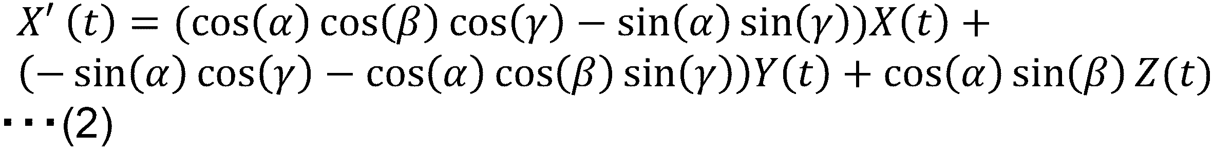
特定部14は、例えば、混合度が1である場合、以下の(5)~(7)に示す動作特徴量の評価関数E11~E13を、それぞれ複数の変換パラメータの候補θ=(α、β、γ)に関して算出する。特定部14は、例えば、E11~E13のそれぞれの最大値を比較する。

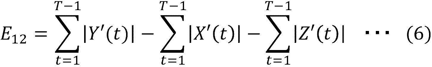
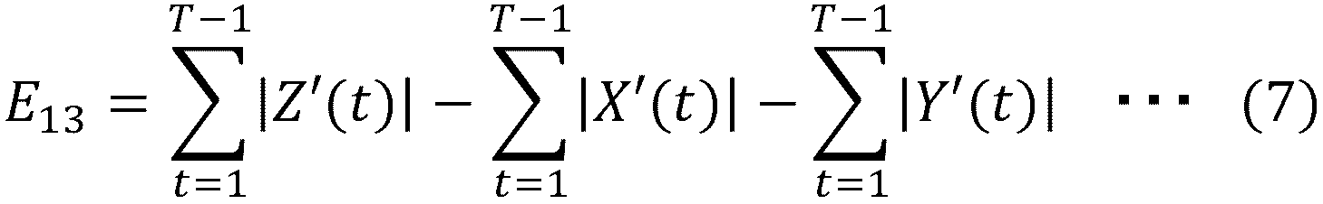
特定部14は、評価関数E11~E13のそれぞれの最大値のうち、E11の最大値が最も大きい場合、X’(t)が代表方向の動作データであると特定する。決定部15は、その場合、E11が第2基準以上(例えば、最大)となる変換パラメータを変換に用いるパラメータに決定する。
特定部14は、評価関数E11~E13のそれぞれの最大値のうち、E12の最大値が最も大きい場合、Y’(t)が代表方向の動作データであると決定する。その場合、決定部15は、E12が第2基準以上(例えば、最大)となる変換パラメータθ=(α、β、γ)を変換に用いるパラメータに決定する。
特定部14は、評価関数E11~E13のそれぞれの最大値のうち、E13の最大値が最も大きい場合、Z’(t)が代表方向の動作データであると特定する。決定部15は、その場合、E13が第2基準以上(例えば、最大)となる変換パラメータθ=(α、β、γ)を変換に用いるパラメータに決定する。
また、特定部14は、例えば、混合度が2である場合、以下の(8)~(10)に示す評価値E21~E23を、それぞれ複数の変換パラメータθ=(α、β、γ)に関して算出する。
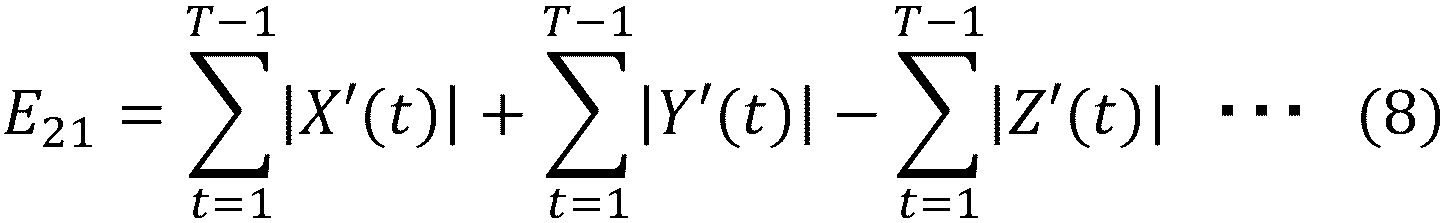

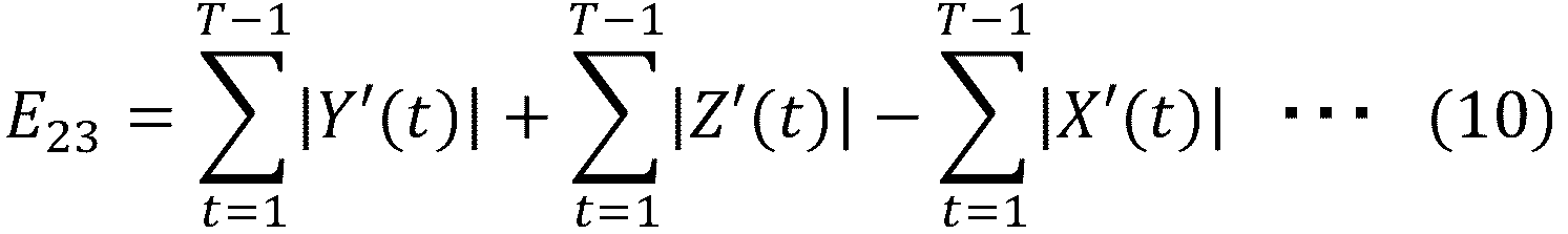
特定部14は、評価関数E21~E23のそれぞれの最大値のうち、E21の最大値が最も大きい場合、X’(t)およびY’(t)が代表方向の動作データであると特定する。決定部15は、その場合、E21が第2基準以上(例えば、最大)となる変換パラメータを変換に用いるパラメータに決定する。
特定部14は、評価関数E21~E23のそれぞれの最大値のうち、E22の最大値が最も大きい場合、X’(t)およびZ’(t)が代表方向の動作データであると特定する。その場合、決定部15は、E22が第2基準以上(例えば、最大)となる変換パラメータを変換に用いるパラメータに決定する。
特定部14は、E21~E23のそれぞれの最大値のうち、E23の最大値が最も大きい場合、Y’(t)およびZ’(t)が代表方向の動作データであると特定する。決定部15は、その場合、E23が第2基準以上(例えば、最大)となる変換パラメータを変換に用いるパラメータに決定する。
また、特定部14は、例えば、混合度が3である場合、以下の(11)に示す評価値E3を、複数の変換パラメータに関して算出する。
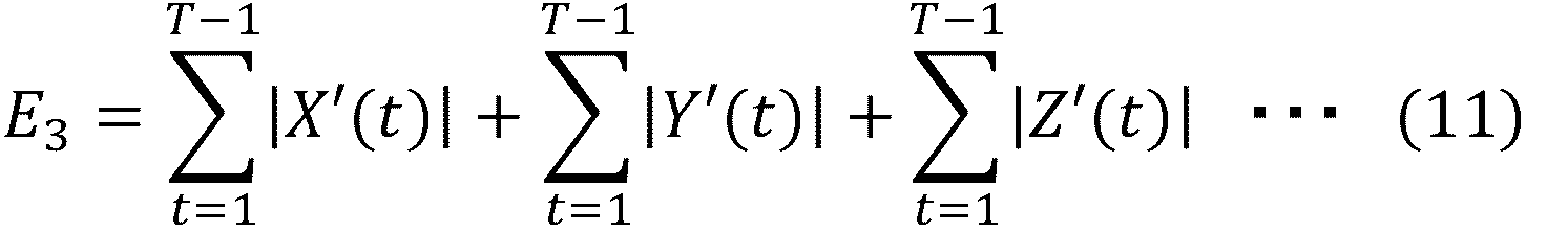
特定部14は、混合度が3である場合、X’(t)、Y’(t)およびZ’(t)が代表方向の動作データであると特定する。決定部15は、その場合、E3が第2基準以上(例えば、最大)となる変換パラメータを変換に用いるパラメータに決定する。
上記の例では、決定部15は、抽出部12が抽出した動作区間毎にパラメータを変換した。決定部15は、動作種類毎に変換パラメータを推定してもよい。決定部15は、例えば、動作種類に基づいて決定した期間(区間)毎に、特定された動作方向における第2の動作特徴量が第2基準以上となるパラメータを決定してもよい。動作種類は、例えば、歩行または方向転換であり、動作種類毎の動作パターンあるいは動作検知アルゴリズムやそのパラメータが予め第1記憶部10に記憶されているとする。そして、決定部15は、動作種類を、記憶された動作パターンとのマッチングに基づいて決定してもよいし、動作検知アルゴリズムを用いて決定してもよい。
また、決定部15は、混合度が共通または類似する動作毎に変換パラメータを決定してもよい。決定部15は、混合度に基づいて決定した期間(区間)毎に、特定された動作方向における動作特徴量が第2基準以上となる前記パラメータを決定してもよい。
動作種類毎、または混合度が共通または類似する動作毎に変換パラメータを決定する場合であって、対象の動作データが複数の動作区間を含んでいる可能性がある。その場合、決定部15は、例えば、複数の区間における評価関数を加算あるいは平均した値が所定基準以上(例えば、最大)となるパラメータを変換に用いるパラメータに決定してもよい。
また、代表方向が予め設定されている場合、決定部15は、設定された代表方向における動作特徴量が第2基準以上(例えば、最大)となる変換パラメータを決定してもよい。例えば、動作が直進歩行である場合、代表方向が前額-水平軸の回転方向であることが推定できるため、代表方向が前額-水平軸の回転方向であることが予め設定される。代表方向が予め設定されている場合、決定部15は、例えば、設定された代表方向における動作特徴量が所定基準以上(例えば、最大)となる変換パラメータを決定してもよい。
図9は、代表方向の数に応じた動作変換前後の動作データの例を示す図である。図9において、実線が変換後の動作データX’(t)、Y’(t)、Z’(t)を示し、点線が変換前の動作データX(t)、Y(t)、Z(t)を示す。
図9(a)は、代表方向が1方向であり、X’(t)が代表方向である場合の動作変換の例を示す。図9(a)に示す例では、X(t)は増加するように変換され、Y(t)およびZ(t)が減少するように変換される。
図9(b)は、代表方向が2方向であり、X’(t)およびY’(t)が代表方向である場合の動作変換の例を示す。図9(b)に示す例では、X(t)およびY(t)は増加するように変換され、Z(t)が減少するように変換される。
図9(c)は、代表方向が3方向であり、X’(t)、Y’(t)およびZ’(t)が代表方向である場合の動作変換の例を示す。図9(c)に示す例では、X(t)、Y(t)およびZ(t)は増加するように変換される。
次に、変換部16は、決定部15が決定した変換パラメータを用いて、動作データを変換する(ステップS107)。例えば、変換部16は、決定部15が決定した変換パラメータθ=(α、β、γ)を式(2)~(4)にそれぞれ代入する。そして、代入後のX’(t)、Y’(t)およびZ’(t)が変換後の動作データとなる。
変換部16は、変換パラメータが既知である場合、既知の変換パラメータを用いて、動作データを変換してもよい。または、変換部16は、既知の変換パラメータと決定した変換パラメータを比較していずれかを選択してもよい。
変換部16は、例えば、センサ4の装着位置のずれが既知である場合に、装着位置に基づいて過去に算出した変換パラメータから変換パラメータを選択してもよい。または、変換部16は、装着者の癖に基づく動作や異常動作が既知である場合に、想定されるセンサ4の装着位置に基づいて過去に算出した変換パラメータから変換パラメータを選択してもよい。
図6に示されるように、情報処理装置1は、全ての動作区間に関してステップS104~S107の処理を完了した場合に、繰り返し処理を終了する(ステップS108)。
図10は、動作変換前後の動作データの例を示す図である。図10(a)~(c)は、1つの代表方向を含む3方向の動作データのうち、代表方向における動作データを示す。図10(a)は、センサ4を正常位置に装着した場合の動作データである。図10(b)は、センサ4を正常ではない位置(回転ずれした位置)に装着した場合の動作データである。図10(c)は、図10(b)の動作データを変換した動作データである。
図10(b)に示す動作データは、センサ4が正常に装着されていないため、代表方向の動作データにおける動作量が図10(a)における動作データと比べて小さい。一方、図10(c)に示すデータは、図10(b)に示す動作データより動作量が大きく、図10(a)における動作データに近いデータとなる。図10(c)に示すデータは、変換後の代表方向の動作特徴量が最大となる変換パラメータを用いて変換が行われたからである。
図11は、動作変換前後の動作データの比較例を示す図である。図11(a)は、代表方向の動作データの一部を示す。図11(a)は、センサ4を正常位置に装着した場合の代表方向の動作データと、センサ4を正常ではない位置(回転ずれした位置)に装着した場合の変換前と変換後の代表方向の動作データとを示す。
図11(a)に示すように、変換後の代表方向の動作データは、センサ4を正常位置に装着した場合の代表方向の動作データに近いデータとなる。
図11(b)は、代表方向以外の動作データの一部を示す。図11(b)は、センサ4を正常位置に装着した場合の代表方向以外の動作データと、センサ4を正常ではない位置(回転ずれした位置)に装着した場合の変換前と変換後の代表方向以外の動作データとを示す。
代表方向以外の動作データは、図11(b)の例に示すように、センサ4を正常でない位置に装着した場合に、正常な位置に装着した場合と比べて動作量が大きい場合がある。一方、変換後の動作データは、正常な位置に装着した場合の動作データに近いデータとなる。
次に、算出部17は、変換された動作データを用いて、特徴量を算出する(ステップS109)。算出部17は、変換された動作データを用いて、動作種類(例えば、歩行、方向転換等)を特定してもよい。算出部17は、例えば、変換後の動作データと、予め記憶された各動作種類のパターンとを比較することにより、動作種類を特定してもよい。算出部17は、既に動作種類が設定されている場合、その動作種類を定量化に用いてもよい。
また、算出部17は、例えば、動作種類が歩行である場合、歩行速度、歩幅などの特徴量を算出(定量化)する。また、算出部17は、例えば、動作種類が方向転換である場合、回転方向、回転量(角度)などの特徴量を算出する。
以上により、本実施形態の情報処理装置1は、変換後の代表方向の動作特徴量が所定基準以上(例えば、最大)となる、変換パラメータを決定し、動作データを変換する。そして、図10、11に示すように、変換後の代表方向の動作特徴量が増加することにより、正常位置に装着されていた場合の動作データに近い動作データを得ることができる。
そのため、センサの初期装着位置が想定された位置からずれていたり、計測対象者の動きによって装着位置が想定された位置と異なる位置に移動したりした場合であっても、動作の定量化の精度低下を抑制することができる。
また、情報処理装置1は、例えば、変換パラメータを蓄積し、可視化することにより、センサ4の状態(装着位置)の変化や異常の把握が可能となる。また、決定された変換パラメータは、パワードスーツなどの動作補助装置の動作方向の決定などにも利用可能である。
また、例えば、患者(計測対象者)の状態を知るために病院で用いられている大規模なモニタリング装置は、設置スペースの確保や導入コスト、操作に対するスキルが要求される等の観点から、患者の自宅又は介護施設に設置することは容易ではない。
そのため、安価で簡便に使用できる装置により患者等の計測対象者の状態を把握することが望ましい。本実施形態の情報処理装置1を用いることにより、例えばジャイロセンサ等の小型の装置を用いて計測対象者の状態を把握することができるので、安価で簡便に計測対象者の動作を定量化することができる。
<第2の実施形態の情報処理装置の一例>
第2の実施形態の情報処理装置について、図面を参照して説明する。以下、特に説明しない構成および機能は、第1の実施形態の情報処理装置と同様であるとする。
第2の実施形態の情報処理装置について、図面を参照して説明する。以下、特に説明しない構成および機能は、第1の実施形態の情報処理装置と同様であるとする。
図12は、第2の実施形態の情報処理装置の一例を示す図である。第2の実施形態の情報処理装置1は、第1の実施形態の情報処理装置1に含まれる構成の他に、第1異常判定部18と、第2異常判定部19とを含む。
第1異常判定部18は、動作データのばらつきに基づいて、センサ4の状態異常を判定する。
第2異常判定部19は、混合度の時間経過に応じた変化に基づいて、センサ4の状態異常を判定する。
<第2の実施形態の処理の流れの一例>
図13、14は、第2の実施形態の情報処理装置の流れの一例を示すフローチャートである。図13、14に示すフローチャートは、図6に示す第1の実施形態のフローチャートに含まれる処理の他に、ステップS204~S207を含む。図13のステップS201~S203、図14のS208~S213は、図6のステップS101~S109の処理と同様である。
図13、14は、第2の実施形態の情報処理装置の流れの一例を示すフローチャートである。図13、14に示すフローチャートは、図6に示す第1の実施形態のフローチャートに含まれる処理の他に、ステップS204~S207を含む。図13のステップS201~S203、図14のS208~S213は、図6のステップS101~S109の処理と同様である。
第1通信部11は、センサ4が測定した動作を示す動作データを受信する(ステップS201)。抽出部12は、受信した動作データから測定対象の動作を示す区間のデータを抽出する(ステップS202)。情報処理装置1は、ステップS202で抽出した動作区間毎の繰り返し処理を開始する(ステップS203)。ステップS203において、Nを動作区間数とすると、各動作区間i(i=1~N)について繰り返し処理が行われる。
第1異常判定部18は、動作区間iにおける代表方向の動作データのばらつきが閾値(第1異常判定閾値)以上であるか判定する(ステップS204)。第1異常判定部18は、例えば、対象動作区間において、代表方向の動作量の最大値が第1異常判定閾値を超えているかを判定する。または、第1異常判定部18は、ある動作区間の動作量の統計値(最大値、平均値等)が一つ前の動作区間の動作量の統計値との差異を算出し、その差異が第1異常判定閾値以上であるかを判定してもよい。
ばらつきが第1異常判定閾値以上である場合(ステップS204でYES)、第1異常判定部18は、センサ4の状態が異常であると判定する(ステップS207)。そして、情報処理装置1は、処理を終了する。
動作データのばらつきが大きい場合、例えば、センサ4が緩く装着され、固定されていないことにより、計測対象者の動作に伴ってセンサ4が振動していることが想定される。その場合、動作データの変換を行っても正しく動作の定量化を行うことが困難であるため、異常であると判定された場合、情報処理装置1は、処理を終了する。
図15は、センサが固定されている場合と固定されていない場合の歩行時の動作データの例を示す。図15(a)は、センサが固定されている場合の歩行時の動作データを示す。図15(b)は、センサが固定されていない場合の歩行時の動作データを示す。
図15(b)に示す動作データは、図15(a)に示す動作データと比べて、例えば、破線部分に示す動作量が大きい。図15(b)に示すように異常な動作データを含む場合、第1異常判定部18は、センサの状態が異常であると判定する。
図13に示されるように、第2異常判定部19は、抽出された動作区間における混合度の時間経過に応じた変化量を算出する(ステップS205)。第2異常判定部19は、例えば、動作区間iにおける所定時間幅内の動作データの累積値について混合度を算出し、時間幅および累積値を変化(例えば、増加)させて混合度を算出する処理を繰り返すことにより、混合度の時間経過に応じた変化量を算出する。
そして、第2異常判定部19は、一つの動作区間中に動作種類が変化しているか判定する(ステップS206)。ステップS206において、第2異常判定部19は、例えば、一つの動作区間中に混合度が変化している場合、動作種類が変化していると判定する。
第2異常判定部19は、一つの動作区間中に動作種類が変化していると判定した場合(ステップS206でYES)、センサ4の状態が異常であると判定する(ステップS207)。そして、情報処理装置1は、処理を終了する。
第2異常判定部19は、例えば、ある動作区間の変換パラメータと、ある動作区間から所定時間離れた動作区間の変換パラメータの差異が閾値(第2異常判定閾値)以上である場合に、センサ4の状態が異常であると判定してもよい。
第2異常判定部19は、例えば、特定の動作区間の変換パラメータと既知の変換パラメータを比較して、差異が第2異常判定閾値以上である場合に、センサ4の状態が異常であると判定してもよい。
図16は、装着位置が徐々に変化する場合の脚の動作データを示す図である。図16(a)は、装着位置が徐々に変化する場合の前額-水平軸方向における脚の動作データである。図16(a)に示す例では、動作量が徐々に減少している。図16(b)は、装着位置が徐々に変化する場合の矢状-水平軸方向における脚の動作データである。図16(b)に示す例では、動作量が徐々に増加している。
図16に示すように、例えば、歩行動作中に代表方向である前額-水平軸方向の動作量が減少し、他の方向の動作量が増加している場合に、センサ4が正常な装着位置から徐々にずれていることが想定される。
図17は、装着位置が徐々に変化する場合の混合度の変化を示す図である。図17に示すように、動作区間の初期では各軸で累積寄与率が累積寄与率閾値を上回るので混合度が1であるが、時間経過とともに1軸の累積寄与率が低下して累積寄与率閾値を下回る。よって、混合度が1から2に変化している。
図16、17に示す例の場合、第2異常判定部19は、一つの動作区間中に動作種類が変化していると判定し、センサ4の状態が異常であると判定する。
ステップS206で動作種類が変化していないと判定された場合、混合度判定部13は、動作区間iについて、動作の代表方向の数を示す混合度を判定する(ステップS208)。特定部14は、混合度に基づいて動作特徴量が第1基準(例えば、最大)となる代表方向を特定する(ステップS209)。決定部15は、代表方向における動作特徴量が第2基準以上(例えば、最大)となるように、動作データの変換に用いるパラメータ(変換パラメータ)を決定する(ステップS210)。
次に、変換部16は、決定部15が決定した変換パラメータを用いて、動作データを変換する(ステップS211)。情報処理装置1は、全ての動作区間に関してステップS204~S211の処理を完了した場合に、繰り返し処理を終了する(ステップS212)。そして、算出部17は、変換された動作データを用いて、特徴量を算出する(ステップS213)。
以上のように、本実施形態の情報処理装置1は、センサ4の状態が異常であるか判定し、異常である場合、処理を終了するので、異常な動作データの変換を行わない。そのため、異常な動作データに基づく定量化を行うことを避けることができる。
<第3の実施形態の情報処理装置の一例>
第3の実施形態の情報処理装置について、図面を参照して説明する。第3の実施形態の情報処理装置について、特に説明しない構成および機能は、第1の実施形態または第2の実施形態の情報処理装置と同じであるとする。第3の実施形態の情報処理装置の構成は、第1の実施形態または第2の実施形態の情報処理装置の構成と同様であるため、説明を省略する。
第3の実施形態の情報処理装置について、図面を参照して説明する。第3の実施形態の情報処理装置について、特に説明しない構成および機能は、第1の実施形態または第2の実施形態の情報処理装置と同じであるとする。第3の実施形態の情報処理装置の構成は、第1の実施形態または第2の実施形態の情報処理装置の構成と同様であるため、説明を省略する。
図18は、歩行中に後ろ向きに歩く動作が含まれる場合の動作データの一例を示す図である。図18は、左右の脚の動作データのうち、代表方向の動作データを示している。図18に示すように、例えば、前向き歩行の動作データの一部に後ろ向き歩行の動作データが含まれている場合、動作データの正負が逆転する。図18に示すような動作データを変換した場合、変換結果が正常にならない可能性がある。
よって、動作データが歩行であることが予め設定されている場合、決定部15は、動作データの正負に依らない動作特徴量に基づいて変換パラメータを決定する。決定部15は、例えば、代表方向における正負に依らない動作特徴量が第2基準以上(例えば、最大)となるように変換パラメータを決定する。正負に依らない動作特徴量は、値が正となる動作特徴量であり、例えば、動作データのピークの絶対値やピーク区間の面積等である。
決定部15は、第1の実施形態で説明したように、式(5)~(11)のいずれかの評価関数が所定基準以上(例えば、最大)となるように変換パラメータを決定してもよい。式(5)~(11)は、各動作データX'(t)、Y'(t)、Z'(t)の絶対値に基づく評価関数であるため、動作データの正負に関わらず、正のデータとなるからである。
歩行中は、進行方向に関わらず前額-水平軸の回転方向を代表方向として脚が回転する。そのため。変換部16は、動作データの正負に依らない動作特徴量に基づいて算出された変換パラメータを用いることにより、前向き歩行と後ろ向き歩行の動作データが混在している場合であっても、適切な変換後データを得ることができる。
図19は、変換パラメータが局所解となる場合の変換前後の動作データを示す図である。τは、動作区間毎に付与された区間番号である。図19に示す例では、区間τの変換パラメータがθ=(150,60,240)であり、区間τ+1での変換パラメータがθ=(150,240,60)である。すなわち、代表方向以外の2方向の変換パラメータが逆転していたとする。
しかし、通常、センサ状態は短時間で大きく変わらないため、図19に示すような変換パラメータは適切ではない可能性が高い。そのため、決定部15は、短時間で大きく変わる変換パラメータを採用しないようにする。
例えば、決定部15は、以下の式(12)のように制約を付加した評価関数を用いて変換パラメータを算出する。
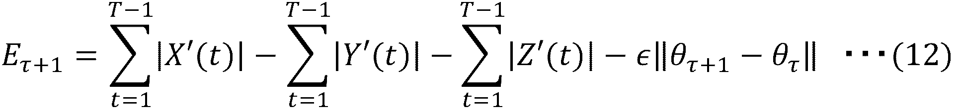
式(12)は、式(5)に制約を付加した例である。θτ+1は、第1動作区間の変換パラメータであり、θτは、事前に算出された、第1動作区間より所定時間前の1または複数の第2動作区間の変換パラメータである。εは、対象動作区間の変換パラメータと一つ前の動作区間の変換パラメータとの差異をどの程度許容するかを示すパラメータである。
決定部15は、式(12)に示すように、第1動作区間(τ+1)での変換パラメータと事前に算出された所定時間前の第2動作区間(τ)での変換パラメータとの差異(例えば、ユークリッド距離)に所定のパラメータを乗算した値を減算する。
決定部15は、例えば、θτ+1に複数の変換パラメータの候補を代入して、式(12)に示す評価関数が最も大きくなるように、変換パラメータを決定する。制約を付加したことにより、第1動作区間(τ+1)での変換パラメータと事前に算出された所定時間前の第2動作区間(τ)での変換パラメータとの差異(例えば、ユークリッド距離)が大きくなるかに応じて評価関数は小さくなるので、差異(例えば、ユークリッド距離)が大きい場合の変換パラメータが変換に用いられる可能性は低くなる。すなわち、変換パラメータが短時間で大きく変化した場合、その変換パラメータは、変換に用いられる可能性は低くなる。
式(12)は、式(5)に対応する評価関数であるが、決定部15は、式(6)~(11)についても、同様の制約(式(12)の第4項)を付加して変換パラメータの決定に用いてよい。
第2動作区間は、例えば、第1動作区間の一つ前の動作区間である。第2動作区間は、例えば、第1動作区間より後の動作区間であってもよい。
決定部15は、例えば、カルマンフィルタ、状態空間モデルを適用し、対象動作区間より前の動作区間の動作データと変換パラメータを用いて、短時間での変化量が少ない変換パラメータを推定してもよい。
以上のように、決定部15は、動作データのうちの第1動作区間における変換パラメータの候補と、第1動作区間より所定時間前の第2動作区間について決定した変換パラメータとの差異を算出する。そして、決定部15は、その差異に基づいて、変換パラメータの候補の中から第1動作区間における変換パラメータを決定する。そのため、情報処理装置1は、例えば、取得した動作データに異常な動作データが含まれていても、適切な変換パラメータを決定することができる。
図20は、異常な動作を含む動作データの区間分離を示す図である。図20に示すように、例えば、動作データの傾向が短時間で大きく変わる場合がある。動作データの傾向が短時間で大きく変わる原因は、例えば、計測対象者がセンサ4を手で触ったり、センサ4が障害物にぶつかったりして衝撃を受けたことによりセンサ4の状態(例えば、装着位置)が変わることである。一つの動作区間に異なるセンサ状態の動作データが含まれる場合、その後、動作区間毎に混合度の判定およびパラメータ変換が行われた際に、適切な結果が得られない可能性がある。
計測対象者がセンサ4を手で触ったり、センサ4が障害物にぶつかるなど、センサ4が衝撃を受けた場合、その衝撃に基づく異常な動作データが発生している場合がある。よって、抽出部12は、ある動作区間の動作データが異常な動作データを含む場合、動作区間を異常な動作データの前後の区間に分離する。抽出部12は、例えば、動作データのピーク値が抽出閾値以上である場合、異常な動作データであると判定する。そして、抽出部12は、分離後の動作区間を混合度判定部13に出力する。
以上のように、抽出部12は、動作データの中の異常動作を示す部分を検知し、前記動作データを、前記異常動作を示す部分より前の区間と、異常動作を示す部分より後の区間とに分離し、分離された各区間を抽出する。区間を分離することにより、一つの動作区間に複数のセンサ状態に基づく動作データが含まれることを抑制することができる。そして、決定部15が、分離後の動作区間毎に変換パラメータを決定することにより、適切なパラメータを決定することができる。
図21は、複数の動作区間における変換後の方向転換の動作データの例を示す図である。図21の動作区間(1)及び動作区間(2)は、方向転換中の動作区間である。方向転換の代表方向は、X’(t)とY’(t)であるとする。図21に示すように、動作区間(1)では、Y’(t)の動作量が最も大きいが、動作区間(2)では、X’(t)の動作量が最も大きい。
図21に示すように、同じ動作種類の動作データであっても、代表方向のうち動作量が最も大きい方向(以下、支配軸方向と称する)が動作区間毎に異なる場合がある。このような動作データを用いて、動作データの変換及び定量化をした場合、精度が低下するおそれがある。よって、特定部14が2つ以上の代表方向を特定した場合、支配軸方向がどの方向かを区別することが好ましい。
決定部15は、例えば、代表方向が2つ以上である場合、各代表方向の変換前の動作データの動作量を算出し、動作量が最も大きい方向(支配軸方向)を決定する。そして、決定部15は、支配軸方向の変換後の動作特徴量が最大となる変換パラメータを決定する。決定部15は、例えば、変換前の動作データの支配軸方向がY(t)である場合、Y’(t)に基づく動作特徴量(例えば、式(8)の第2項)が最大となる変換パラメータを決定する。
ただし、決定部15は、歩行など、動作種類が事前に分かっている場合は、動作種類に応じて支配軸方向を決定してもよい。例えば、動作種類が歩行である場合は、前額-水平軸の回転方向を支配軸方向であると決定してもよい。また、決定部15は、同じ種類の動作が複数回繰り返されている場合には、複数回の動作に対応する動作データ中で合計の動作量が最も大きい方向、または、変換後に最も合計の動作量が大きくなる方向を支配軸方向と決定してもよい。
以上のように、代表方向が2つ以上である場合、決定部15は、代表方向のうち最も動作量が大きい方向の動作特徴量が最大となるパラメータを決定するので、定量化精度の低下を抑制することができる。
図22は、方向転換の変換後の動作データを示す図である。図22(a)は、正常に変換された場合の動作データを示す。図22(b)は、正常に変換されなかった場合の動作データを示す。
本実施形態では、Y’(t)が正である場合、右旋回を示し、Y’(t)が負である場合、左旋回を示すとする。しかし、図22(b)に示すように、本来右旋回の動作データが変換によって負のデータとなる場合がある。
図22に示す例では、X’(t)が前額-水平軸の回転方向の動作データであるとする。前向き歩行中に旋回した場合、旋回方向に関係なく脚は前に回転するため、X’(t)は、通常、正となる。しかし、図22(b)では、X’(t)が負のデータとなっているため、異常な動作データであることが分かる。すなわち、例えば、前向きの歩行中の動作データであることが分かっていれば、X’(t)の動作データの正負に基づいて、変換後の動作データが正常か判定することが可能である。
よって、決定部15は、例えば、動作の種類が方向転換であることを示す場合、X’(t)の動作データが正となるように変換パラメータを決定する。以下の式(13)は、式(8)においてX'(t)の絶対値を外した式である。
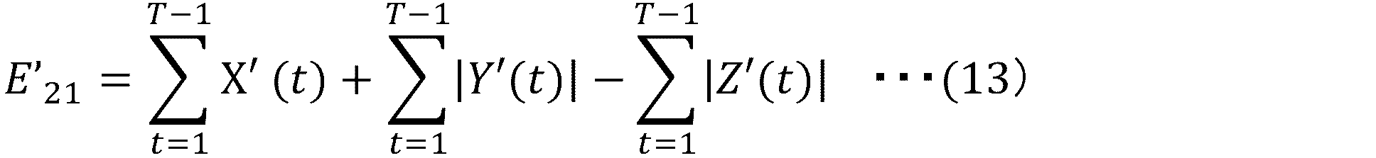
式(13)に示すように、複数の代表方向の動作データのうち、支配軸の回転方向ではない動作データX'(t)の絶対値を外したことにより、X'(t)が負である場合の変換パラメータは実際に変換に用いるパラメータとして採用されづらくなる。よって、X’(t)の動作データが正となるように変換パラメータが決定される。
以上のように、情報処理装置1は、複数の代表方向のうち一つの方向が既知であれば、既知の方向の動作データの正負に基づいて、変換パラメータを決定するので、本来の動作データと正負が逆転する可能性を抑制することができる。 図23は、脚の回転方向を示す図である。通常、動作が直進歩行である場合、前額-水平軸の回転方向が代表方向となる。特定部14は、ステップS105またはS209の処理において、代表方向を特定する。しかし、動作データの変換処理によって代表方向以外の方向の動作データが入れ替わって推定される場合がある。
例えば、前額-水平軸の回転方向がX’(t)である場合に、矢状-水平軸の回転方向の動作データがY’(t)として出力される場合があり、Z’(t)として出力されてしまう場合がある。また、垂直軸の回転方向の動作データがZ’(t)として出力されてしまう場合があり、Y’(t)として出力される場合もある。
通常、動作が直進歩行である場合、矢状-水平軸の回転方向は、垂直軸の回転方向の動作量と比較して小さい。歩行中に足首を回転させる動作が行われる可能性はあるが、横に振り上げる動作は、通常、行われないからである。よって、決定部15は、代表方向ではない方向の動作データのうち、動作量が大きい方向の動作データが垂直軸の回転方向の動作データ(本実施形態では、Y’(t))となるように変換パラメータを決定する。
決定部15は、例えば、式(5)に制約条件を加えた下記式(14)に基づいて、変換パラメータを算出してもよい。式(14)を用いた場合、垂直軸の回転方向の動作データがY’(t)となり、矢状-水平軸の回転方向は、Z’(t)となることが想定される。

以上、直進歩行の場合の例について説明したが、直進歩行の場合に限定されない。代表方向以外の方向の動作データの大小関係が既知であれば、決定部15は、その大小関係を制約として用いて変換パラメータを決定すればよい。
以上のように、情報処理装置1は、代表方向以外の方向の動作データの大小関係が既知である場合に、大小関係を制約として用いて変換パラメータを決定するので、代表方向以外の方向の動作データが変換により入れ替わることを抑制することができる。
<第1の実施例>
第1の実施例として、計測対象者が左脚にセンサ4を1個装着し、右脚にセンサ4を5個装着した場合の、直進歩行中の歩き方の特徴を定量化する例を説明する。
第1の実施例として、計測対象者が左脚にセンサ4を1個装着し、右脚にセンサ4を5個装着した場合の、直進歩行中の歩き方の特徴を定量化する例を説明する。
図24は、第1の実施例における抽出部12が取得した各センサ4からの動作データである。図24では、代表方向の動作データのみを示し、代表方向以外の動作データの図示を省略する。図24に示す例では、右脚に装着したセンサ4はそれぞれ異なる位置に装着されているため、動作データも異なっている。
図25は、動作抽出アルゴリズムの例を示す図である。抽出部12は、動作抽出アルゴリズムDB10aから、予め指定された動作を抽出するためのアルゴリズムを取得し、検出対象の動作を示す区間のデータを抽出する。
図25に示すように、動作抽出アルゴリズムは、アルゴリズムNo.と、動作抽出に用いる各パラメータを含む。パラメータは、例えば、合成値のピーク値、合成値のピーク間隔、合成値のピーク幅、及び合成値のピーク勾配である。各アルゴリズムは、例えば、パラメータの要否(○または×)、各パラメータの閾値を含む。動作抽出アルゴリズムは、各パラメータを用いた抽出方法を含んでいてもよい。
動作抽出アルゴリズムは、例えば、動作種類毎に記憶されている。本実施例では、動作抽出アルゴリズムDB10aは、歩行動作に対応するアルゴリズムNo1を適用する。
図26は、抽出された動作区間の例を示す図である。図26に示すように、動作データのうち、検出対象の動作を示す部分が抽出される。
次に、混合度判定部13は、混合度の判定指標を含む判定指標DB10bから、対象動作に対応する判定指標を取得し、判定指標に基づいて混合度を判定する。
図27は、混合度の判定指標の例を示す図である。図27に示すように、判定指標DB10bには、判定指標の定義Noと、対象動作と、混合度の判定指標とが対応付けられて記憶されている。また、混合度の判定指標は、主成分分析の累積寄与率の閾値、独立成分分析の比の閾値、その他の動作データのばらつきを示す値(例えば、共分散、標準偏差等)の閾値を含む。すなわち、混合度の判定指標は、3次元の動作方向を含む動作データのばらつきを評価する判定閾値(例えば、ばらつきの大きさの最小閾値等)である。
混合度判定部13は、動作データの判定指標に対応する値が閾値以上である軸の数のうち、最も少ない軸の数を混合度に用いる。本実施例では、対象動作は直進歩行であるため、定義No1の判定指標を混合度の判定に用いる。混合度判定部13は、定義No1の判定指標を用いて混合度を判定し、混合度が「1」であったとする。
次に、特定部14は、混合度に基づいて代表方向を特定する。本実施例では、混合度が「1」であるため、特定部14は、複数の方向の動作特徴量のうち動作特徴量が最大となる方向を代表方向であると特定する。
次に、決定部15は、代表方向における動作特徴量が最大となるように変換パラメータを決定する。
図28は、状態変換量DBに記憶される情報の例を示す図である。決定部15は、決定した変換パラメータを状態変換量DB10cに記憶させる。図28に示すように、状態変換量DBは、日時と、動作開始時刻と、動作終了時刻と、状態変換量とが対応付けられて記憶されている。状態変換量は、例えば、X軸回転量(α)と、Y軸回転量(β)と、Z軸回転量(γ)とを含む。状態変換量は、変換パラメータに対応する。
決定部15が決定した変換パラメータを状態変換量DB10cに記憶させ、一定量のデータを蓄積させて可視化することにより、センサ状態(位置)の変化や異常の把握の確認が可能となる。
次に、変換部16は、決定部15が決定した変換パラメータを用いて、動作データを変換する。図29は、変換前後の動作データの例を示す図である。図29において、X’(t)は前額-水平軸の回転方向の動作データであり、Y’(t)は、垂直軸の回転方向の動作データであり、Z’(t)は、矢状-水平軸の回転方向の動作データである。また、図29は、右脚(1)の3方向(X’(t)、Y’(t)、Z’(t))の変換前後の動作データと、右脚(2)~(5)のX’(t)の変換前後の動作データを含む。左脚の動作データ、右脚(2)~(5)のY’(t)、Z’(t)の動作データの図示は、省略されている。
図29において、右脚(1)の変換パラメータは、θ=(150,60,240)であり、右脚(2)の変換パラメータは、θ=(300,330,60)であり、右脚(3)の変換パラメータは、θ=(180,60,360)であるとする。また、右脚(4)の変換パラメータは、θ=(330,60,240)であり、右脚(5)の変換パラメータは、θ=(330,360,30)であるとする。
図29に示すように、X’(t)に関しては、変換により動作量が増加している。また、Y’(t)、Z’(t)は、変換により動作量が減少している。本実施例では、動作は歩行であり、X’(t)が代表方向であるため、変換により代表方向の動作量が増加し、代表方向以外の動作量が減少したこととなる。変換後の動作データは、センサ4を正常位置に装着した場合の動作データに近いデータとなる。
次に、算出部17は、変換された動作データを用いて動作種類を特定し、動作を定量化する。本実施例では、算出部17は、変換された動作データが歩行であると特定したとする。算出部17は、変換された動作データに基づいて、歩行に関する特徴量を定量化し、特徴量DB10dに記憶させる。
図30は、特徴量DBに記憶される歩行に関する動作特徴量の例を示す図である。図30に示すように、歩行に関する動作特徴量は、日時、左脚歩行速度、右脚歩行速度、左脚歩幅、右脚歩幅を示す。
算出部17は、例えば、動作データの振幅を歩行速度として特徴量DB10dに記憶させる。算出部17は、例えば、動作データの積分値に基づいて歩行幅を算出し、歩行幅を特徴量DB10dに記憶させる。
<第2の実施例>
第2の実施例として、計測対象者が左脚にセンサ4を1個装着し、右脚にセンサ4を5個装着した場合の、方向転換中の歩き方の特徴を定量化する例を説明する。本実施例において、特に記載しない処理は、第1の実施例と同様であるとする。
第2の実施例として、計測対象者が左脚にセンサ4を1個装着し、右脚にセンサ4を5個装着した場合の、方向転換中の歩き方の特徴を定量化する例を説明する。本実施例において、特に記載しない処理は、第1の実施例と同様であるとする。
図31は、第2の実施例における抽出部12が取得した各センサ4からの動作データである。図31では、代表方向の動作データのみを示し、代表方向以外の動作データの図示を省略する。図31に示す例では、右脚に装着したセンサ4はそれぞれ異なる位置に装着されているため、動作データも異なっている。
抽出部12は、動作抽出アルゴリズムDB10aから、予め指定された動作を抽出するためのアルゴリズムを取得し、検出対象の動作を示す区間のデータを抽出する。本実施例では、図25のアルゴリズムNo2に対応付けられているアルゴリズムを用いて、検出対象の動作を示す区間のデータを抽出する。
次に、混合度判定部13は、混合度の判定指標を含む判定指標DB10bから、対象動作に対応する判定指標を取得し、判定指標に基づいて混合度を判定する。本実施例では、混合度判定部13は、図27の定義No2に対応付けられている混合度判定指標を用いて、混合度を判定する。本実施例では、混合度判定部13は、混合度が「2」であると判定したとする。
次に、特定部14は、混合度に基づいて代表方向を特定する。本実施例では、混合度が「2」であるため、特定部14は、2方向の動作特徴量の合計のうち最大となる2方向を代表方向であると特定する。
次に、決定部15は、代表方向における動作特徴量が最大となるように変換パラメータを決定する。
次に、変換部16は、決定部15が決定した変換パラメータを用いて、動作データを変換する。図32は、変換前後の動作データの例を示す図である。図32において、X’(t)は前額-水平軸の回転方向の動作データであり、Y’(t)は、垂直軸の回転方向の動作データであり、Z’(t)は、矢状-水平軸の回転方向の動作データである。また、図32は、右脚(1)の3方向(X’(t)、Y’(t)、Z’(t))の変換前後の動作データと、右脚(2)~(5)のX’(t)の変換前後の動作データを含む。左脚の動作データ、右脚(2)~(5)のY’(t)、Z’(t)の動作データの図示は、省略されている。
図32において、右脚(1)の変換パラメータは、θ=(150,120,360)であり、右脚(2)の変換パラメータは、θ=(150,150,360)であり、右脚(3)の変換パラメータは、θ=(150,210,360)であるとする。また、右脚(4)の変換パラメータは、θ=(150,240,180)であり、右脚(5)の変換パラメータは、θ=(150,150,180)であるとする。
次に、算出部17は、変換された動作データを用いて動作種類を特定し、動作を定量化する。本実施例では、算出部17は、変換された動作データが方向転換であると特定したとする。算出部17は、変換された動作データに基づいて、方向転換に関する特徴量を定量化し、特徴量DB10dに記憶させる。
図33は、特徴量DBに記憶される方向転換に関する動作特徴量の例を示す図である。図33に示すように、方向転換に関する動作特徴量は、日時、左脚回転方向、右脚回転方向、左脚回転量、右脚回転量を示す。
算出部17は、例えば、動作データの動作量が正であれば右回転方向、負であれば左回転であると判定し、回転方向を特徴量DB10dに記憶させる。算出部17は、例えば、動作データの1周期内の積分値に基づいて回転量(回転角度)を算出し、回転量を特徴量DB10dに記憶させる。
<情報処理装置のハードウェア構成の一例>
次に、図34の例を参照して、情報処理装置のハードウェア構成の一例を説明する。図34の例に示すように、バス100に対して、プロセッサ111とRandom Access Memory(RAM)112とRead Only Memory(ROM)113とが接続される。また、該バス100に対して、補助記憶装置114と媒体接続部115と通信インタフェース116とが接続される。
次に、図34の例を参照して、情報処理装置のハードウェア構成の一例を説明する。図34の例に示すように、バス100に対して、プロセッサ111とRandom Access Memory(RAM)112とRead Only Memory(ROM)113とが接続される。また、該バス100に対して、補助記憶装置114と媒体接続部115と通信インタフェース116とが接続される。
プロセッサ111はRAM112に展開されたプログラムを実行する。実行されるプログラムとしては、実施形態における処理を行う情報処理プログラムが適用されてもよい。
ROM113はRAM112に展開されるプログラムを記憶する不揮発性の記憶装置である。補助記憶装置114は、種々の情報を記憶する記憶装置であり、例えばハードディスクドライブや半導体メモリ等を補助記憶装置114に適用してもよい。媒体接続部115は、可搬型記録媒体118と接続可能に設けられている。
可搬型記録媒体118としては、可搬型のメモリや光学式ディスク(例えば、Compact Disc(CD)やDigital Versatile Disc(DVD))、半導体メモリ等を適用してもよい。この可搬型記録媒体118に実施形態の処理を行う情報処理プログラムが記録されていてもよい。
図4、12に示す第1記憶部10は、RAM112や補助記憶装置114等により実現されてもよい。図4及び図12に示す第1通信部11は、通信インタフェース116により実現されてもよい。
図4、12に示す抽出部12、混合度判定部13、特定部14、決定部15、変換部、算出部、並びに図12に示す第1異常判定部18及び第2異常判定部19は、与えられた情報処理プログラムをプロセッサ111が実行することにより実現されてもよい。
RAM112、ROM113、補助記憶装置114および可搬型記録媒体118は、何れもコンピュータ読み取り可能な有形の記憶媒体の一例である。これらの有形な記憶媒体は、信号搬送波のような一時的な媒体ではない。
<その他>
本実施形態は、以上に述べた実施の形態に限定されるものではなく、本実施形態の要旨を逸脱しない範囲内で種々の構成または実施形態を取ることができる。
本実施形態は、以上に述べた実施の形態に限定されるものではなく、本実施形態の要旨を逸脱しない範囲内で種々の構成または実施形態を取ることができる。
1 情報処理装置
2 ネットワーク
3 中継装置
4 センサ
10 第1記憶部
11 第1通信部
12 抽出部
13 混合度判定部
14 特定部
15 決定部
16 変換部
17 算出部
18 第1異常判定部
19 第2異常判定部
111 プロセッサ
112 RAM
113 ROM
2 ネットワーク
3 中継装置
4 センサ
10 第1記憶部
11 第1通信部
12 抽出部
13 混合度判定部
14 特定部
15 決定部
16 変換部
17 算出部
18 第1異常判定部
19 第2異常判定部
111 プロセッサ
112 RAM
113 ROM
Claims (21)
- 動作を測定するセンサと、
前記センサから前記動作に関する動作データを受信する情報処理装置と、
を備え、
前記情報処理装置は、
前記動作データに基づいて、第1の動作特徴量が第1基準以上となる1または複数の動きの方向を特定する特定部と、
前記特定された方向を用いて、変換後の前記方向での第2の動作特徴量が第2基準以上となる、前記動作データの変換に用いられるパラメータを決定する決定部と、
を含む、
ことを特徴とする情報処理システム。 - 前記特定部は、前記動作データに基づいて、前記第1の動作特徴量が最大となる前記1または複数の動きの方向を特定する、
ことを特徴とする請求項1記載の情報処理システム。 - 前記決定部は、前記特定された方向における前記第2の動作特徴量が最大となる、前記動作データの変換に用いられるパラメータを決定する、
ことを特徴とする請求項1または2記載の情報処理システム。 - 前記情報処理装置は、
前記動作データの動作特徴量が抽出閾値以上となる区間の前記動作データを抽出する抽出部を含む、
ことを特徴とする請求項1乃至3のうちのいずれか1項に記載の情報処理システム。 - 前記情報処理装置は、
前記動作データに基づいて、前記動きの方向の数を示す混合度を判定する混合度判定部を含む、
ことを特徴とする請求項1乃至4のうちのいずれか1項に記載の情報処理システム。 - 前記情報処理装置は、
決定された前記パラメータを用いて前記動作データを変換する変換部を含む、
ことを特徴とする請求項1乃至5のうちのいずれか1項に記載の情報処理システム。 - 前記情報処理装置は、
変換された前記動作データに基づいて、前記動作の特徴量を算出する算出部を含む
ことを特徴とする請求項6に記載の情報処理システム。 - 前記混合度判定部は、
3次元の各方向における前記動作データのばらつきに基づいて前記混合度を判定する
ことを特徴とする請求項5記載の情報処理システム。 - 前記決定部は、
前記動作の種類に基づいて決定した期間毎に、前記特定された方向における前記第2の動作特徴量が前記第2基準以上となる前記パラメータを決定する
ことを特徴とする請求項1乃至8のうちのいずれか1項に記載の情報処理システム。 - 前記決定部は、
前記混合度に基づいて決定した期間毎に、前記特定された方向における前記第2の動作特徴量が前記第2基準以上となる前記パラメータを決定する
ことを特徴とする請求項5に記載の情報処理システム。 - 前記情報処理装置は、
前記動作データのばらつきに基づいて、前記センサの状態異常を判定する第1異常判定部を含む、
ことを特徴とする請求項1乃至10のうちのいずれか1項に記載の情報処理システム。 - 前記情報処理装置は、
前記混合度の時間経過に応じた変化量に基づいて、前記センサの状態異常を判定する第2異常判定部を含む、
ことを特徴とする請求項5に記載の情報処理システム。 - 前記決定部は、
前記動作の種類が歩行である場合、前記特定された方向の前記第2の動作特徴量であって値が正となる前記第2の動作特徴量が前記第2基準以上となる前記パラメータを決定する、
ことを特徴とする請求項1乃至12のうちのいずれか1項に記載の情報処理システム。 - 前記決定部は、
前記動作データのうちの第1動作区間における前記パラメータの候補と、前記第1動作区間より所定時間前または所定時間後の1または複数の第2動作区間について決定したパラメータとの差異に基づいて、前記パラメータの候補の中から前記第1動作区間における前記パラメータを決定する
ことを特徴とする請求項1乃至13のうちのいずれか1項に記載の情報処理システム。 - 前記抽出部は、
前記動作データの中の異常動作を示す部分を検知し、前記動作データを、前記異常動作を示す部分より前の区間と、前記異常動作を示す部分より後の区間とに分離し、分離された各区間を抽出する、
ことを特徴とする請求項4に記載の情報処理システム。 - 前記決定部は、
前記特定された方向が2つ以上である場合、前記方向のうち最も動作量が大きい方向の前記第2の動作特徴量が前記第2基準以上となるパラメータを決定する
ことを特徴とする請求項1乃至15のうちのいずれか1項に記載の情報処理システム。 - 前記決定部は、
前記動作の種類が方向転換である場合、前記特定された方向のうち動作量が最も少ない方向の動作データの値が正となる、前記パラメータを決定する
ことを特徴とする請求項1乃至16のうちのいずれか1項に記載の情報処理システム。 - 前記決定部は、
前記動作の種類が直進歩行である場合、前記特定された方向以外の方向のうち、動作量が最も大きい方向が水平面に直交する垂直軸の回転方向となる前記パラメータを決定する
ことを特徴とする請求項1乃至17のうちのいずれか1項に記載の情報処理システム。 - 動作を測定するセンサから前記動作に関する動作データを受信する通信部と、
前記動作データに基づいて、第1の動作特徴量が第1基準以上となる1または複数の動きの方向を特定する特定部と、
前記特定された方向を用いて、変換後の前記方向での第2の動作特徴量が第2基準以上となる、前記動作データの変換に用いられるパラメータを決定する決定部と、
を備えることを特徴とする情報処理装置。 - 動作を測定するセンサから前記動作に関する動作データを受信し、
前記動作データに基づいて、第1の動作特徴量が第1基準以上となる1または複数の動きの方向を特定し、
前記特定された方向を用いて、変換後の前記方向での第2の動作特徴量が第2基準以上となる、前記動作データの変換に用いられるパラメータを決定する、
処理をコンピュータが実行することを特徴とする情報処理方法。 - 動作を測定するセンサから前記動作に関する動作データを受信し、
前記動作データに基づいて、第1の動作特徴量が第1基準以上となる1または複数の動きの方向を特定し、
前記特定された方向を用いて、変換後の前記方向での第2の動作特徴量が第2基準以上となる、前記動作データの変換に用いられるパラメータを決定する、
処理をコンピュータに実行させることを特徴とする情報処理プログラム。
Priority Applications (4)
| Application Number | Priority Date | Filing Date | Title |
|---|---|---|---|
| PCT/JP2016/083996 WO2018092219A1 (ja) | 2016-11-16 | 2016-11-16 | 情報処理システム、情報処理装置、情報処理方法および情報処理プログラム |
| EP16921827.8A EP3542719B1 (en) | 2016-11-16 | 2016-11-16 | Information processing system, information processing device and information processing method |
| JP2018550920A JP6791260B2 (ja) | 2016-11-16 | 2016-11-16 | 情報処理システム、情報処理装置、情報処理方法および情報処理プログラム |
| FIEP16921827.8T FI3542719T3 (fi) | 2016-11-16 | 2016-11-16 | Informaation käsittelyjärjestelmä, informaation prosessointilaite ja informaation prosessointimenetelmä |
Applications Claiming Priority (1)
| Application Number | Priority Date | Filing Date | Title |
|---|---|---|---|
| PCT/JP2016/083996 WO2018092219A1 (ja) | 2016-11-16 | 2016-11-16 | 情報処理システム、情報処理装置、情報処理方法および情報処理プログラム |
Publications (1)
| Publication Number | Publication Date |
|---|---|
| WO2018092219A1 true WO2018092219A1 (ja) | 2018-05-24 |
Family
ID=62145288
Family Applications (1)
| Application Number | Title | Priority Date | Filing Date |
|---|---|---|---|
| PCT/JP2016/083996 Ceased WO2018092219A1 (ja) | 2016-11-16 | 2016-11-16 | 情報処理システム、情報処理装置、情報処理方法および情報処理プログラム |
Country Status (4)
| Country | Link |
|---|---|
| EP (1) | EP3542719B1 (ja) |
| JP (1) | JP6791260B2 (ja) |
| FI (1) | FI3542719T3 (ja) |
| WO (1) | WO2018092219A1 (ja) |
Cited By (3)
| Publication number | Priority date | Publication date | Assignee | Title |
|---|---|---|---|---|
| WO2020157808A1 (ja) | 2019-01-28 | 2020-08-06 | 富士通株式会社 | センサ着脱判定プログラム、システム、及び方法 |
| JP2022064449A (ja) * | 2020-10-14 | 2022-04-26 | 株式会社日立製作所 | 行動解析システム及びそれを用いた行動解析方法 |
| WO2024075363A1 (ja) * | 2022-10-04 | 2024-04-11 | 日鉄ソリューションズ株式会社 | 情報処理装置、情報処理方法及びプログラム |
Citations (5)
| Publication number | Priority date | Publication date | Assignee | Title |
|---|---|---|---|---|
| JP2005172625A (ja) | 2003-12-11 | 2005-06-30 | Matsushita Electric Ind Co Ltd | 行動検知装置 |
| WO2007052631A1 (ja) | 2005-10-31 | 2007-05-10 | Bycen Inc. | 歩様バランス定量化方法および歩様バランス定量化装置 |
| JP2013106768A (ja) * | 2011-11-21 | 2013-06-06 | Seiko Epson Corp | 状態検出装置、電子機器及びプログラム |
| JP2013532539A (ja) | 2010-07-27 | 2013-08-19 | コーニンクレッカ フィリップス エレクトロニクス エヌ ヴィ | ボディマウントされたデバイスに対する自動方向較正 |
| JP2016112108A (ja) * | 2014-12-12 | 2016-06-23 | カシオ計算機株式会社 | 運動情報表示システム及び運動情報表示方法、運動情報表示プログラム |
Family Cites Families (6)
| Publication number | Priority date | Publication date | Assignee | Title |
|---|---|---|---|---|
| US6813582B2 (en) * | 2002-07-31 | 2004-11-02 | Point Research Corporation | Navigation device for personnel on foot |
| JP2007117601A (ja) * | 2005-10-31 | 2007-05-17 | Konica Minolta Sensing Inc | 睡眠時無呼吸指数測定装置 |
| JP2014042606A (ja) * | 2012-08-24 | 2014-03-13 | Panasonic Corp | 体動判定装置及び電気刺激装置 |
| WO2014153725A1 (en) * | 2013-03-26 | 2014-10-02 | Google Inc. | Signal processing to extract a pedestrian's moving direction |
| JP2014226451A (ja) * | 2013-05-27 | 2014-12-08 | 昭和電工株式会社 | 睡眠状態計測装置及び睡眠状態計測方法 |
| JP2016120271A (ja) * | 2014-11-17 | 2016-07-07 | ルネサスエレクトロニクス株式会社 | 位相補正装置、行動識別装置、行動識別システム、マイクロコントローラ、位相補正方法、及びプログラム |
-
2016
- 2016-11-16 FI FIEP16921827.8T patent/FI3542719T3/fi active
- 2016-11-16 JP JP2018550920A patent/JP6791260B2/ja not_active Expired - Fee Related
- 2016-11-16 WO PCT/JP2016/083996 patent/WO2018092219A1/ja not_active Ceased
- 2016-11-16 EP EP16921827.8A patent/EP3542719B1/en active Active
Patent Citations (5)
| Publication number | Priority date | Publication date | Assignee | Title |
|---|---|---|---|---|
| JP2005172625A (ja) | 2003-12-11 | 2005-06-30 | Matsushita Electric Ind Co Ltd | 行動検知装置 |
| WO2007052631A1 (ja) | 2005-10-31 | 2007-05-10 | Bycen Inc. | 歩様バランス定量化方法および歩様バランス定量化装置 |
| JP2013532539A (ja) | 2010-07-27 | 2013-08-19 | コーニンクレッカ フィリップス エレクトロニクス エヌ ヴィ | ボディマウントされたデバイスに対する自動方向較正 |
| JP2013106768A (ja) * | 2011-11-21 | 2013-06-06 | Seiko Epson Corp | 状態検出装置、電子機器及びプログラム |
| JP2016112108A (ja) * | 2014-12-12 | 2016-06-23 | カシオ計算機株式会社 | 運動情報表示システム及び運動情報表示方法、運動情報表示プログラム |
Non-Patent Citations (3)
| Title |
|---|
| FRACCARO ET AL.: "Real-world Gyroscope- based Gait Event Detection and Gait Feature Extraction", ETELEMED, 2014 |
| See also references of EP3542719A4 |
| VAN LUMMEL ET AL.: "Automated approach for quantifying the repeated sit-to-stand using one body fixed sensor in young and older adults", GAIT & POSTURE, vol. 38, 2013, pages 153 - 156, XP028554904, DOI: doi:10.1016/j.gaitpost.2012.10.008 |
Cited By (5)
| Publication number | Priority date | Publication date | Assignee | Title |
|---|---|---|---|---|
| WO2020157808A1 (ja) | 2019-01-28 | 2020-08-06 | 富士通株式会社 | センサ着脱判定プログラム、システム、及び方法 |
| EP3918990A4 (en) * | 2019-01-28 | 2022-02-09 | Fujitsu Limited | PROGRAM, SYSTEM AND PROCEDURE FOR IDENTIFICATION OF SENSOR ATTACHMENT/SOLUTION |
| JP2022064449A (ja) * | 2020-10-14 | 2022-04-26 | 株式会社日立製作所 | 行動解析システム及びそれを用いた行動解析方法 |
| JP7449838B2 (ja) | 2020-10-14 | 2024-03-14 | 株式会社日立製作所 | 行動解析システム及びそれを用いた行動解析方法 |
| WO2024075363A1 (ja) * | 2022-10-04 | 2024-04-11 | 日鉄ソリューションズ株式会社 | 情報処理装置、情報処理方法及びプログラム |
Also Published As
| Publication number | Publication date |
|---|---|
| EP3542719A4 (en) | 2019-11-06 |
| JP6791260B2 (ja) | 2020-11-25 |
| JPWO2018092219A1 (ja) | 2019-06-24 |
| EP3542719A1 (en) | 2019-09-25 |
| EP3542719B1 (en) | 2023-01-25 |
| FI3542719T3 (fi) | 2023-03-16 |
Similar Documents
| Publication | Publication Date | Title |
|---|---|---|
| JP5674766B2 (ja) | 着用位置を検出するためのセンシングデバイス | |
| JP6951516B2 (ja) | 人の歩調を検出する方法及びシステム | |
| JP4590018B1 (ja) | 特徴量変換装置、および特徴量変換方法 | |
| US9659150B2 (en) | Method for assessing cognitive function and predicting cognitive decline through quantitative assessment of the TUG test | |
| KR20160031246A (ko) | 보행 환경 인식 방법 및 장치 | |
| JP6724984B2 (ja) | 情報処理装置、情報処理方法、及び情報処理プログラム | |
| CN112438724A (zh) | 跌倒风险评估方法、跌倒风险评估装置以及记录介质 | |
| CN107708553B (zh) | 行为识别装置、空气调节机以及机器人控制装置 | |
| KR101908176B1 (ko) | 보행 보조기를 위한 보행 상태 추정 방법 및 장치 | |
| CN108629304B (zh) | 一种冻结步态在线检测方法 | |
| JPWO2018211550A1 (ja) | 情報処理装置、情報処理システム及び情報処理方法 | |
| CN112438722A (zh) | 肌肉衰减症评估方法、评估装置以及存储介质 | |
| JP6791260B2 (ja) | 情報処理システム、情報処理装置、情報処理方法および情報処理プログラム | |
| Dolatabadi et al. | Automated classification of pathological gait after stroke using ubiquitous sensing technology | |
| US11494702B2 (en) | Task estimation method and information processing apparatus | |
| Ghobadi et al. | A robust automatic gait monitoring approach using a single IMU for home-based applications | |
| US10993640B2 (en) | System and method for monitoring the movement of a part of a human body | |
| Nie et al. | An adaptive gait event detection method based on stance point for walking assistive devices | |
| JP6638860B2 (ja) | 情報処理システム、情報処理装置、および情報処理方法 | |
| Reiss et al. | Activity recognition using biomechanical model based pose estimation | |
| EP3847961B1 (en) | Walking state determination program, walking state determination method, and information processing device | |
| Redmond et al. | Automatic segmentation of triaxial accelerometry signals for falls risk estimation | |
| EP3603505A1 (en) | Information processing system, information processing device, and information processing method | |
| WO2018211713A1 (ja) | 情報処理装置、情報処理システム、および情報処理方法 | |
| Er et al. | Evaluation of single HMM as a pre-impact fall detector based on different input signals |
Legal Events
| Date | Code | Title | Description |
|---|---|---|---|
| 121 | Ep: the epo has been informed by wipo that ep was designated in this application |
Ref document number: 16921827 Country of ref document: EP Kind code of ref document: A1 |
|
| ENP | Entry into the national phase |
Ref document number: 2018550920 Country of ref document: JP Kind code of ref document: A |
|
| NENP | Non-entry into the national phase |
Ref country code: DE |
|
| ENP | Entry into the national phase |
Ref document number: 2016921827 Country of ref document: EP Effective date: 20190617 |