WO2018087952A1 - 電気掃除機 - Google Patents
電気掃除機 Download PDFInfo
- Publication number
- WO2018087952A1 WO2018087952A1 PCT/JP2017/021222 JP2017021222W WO2018087952A1 WO 2018087952 A1 WO2018087952 A1 WO 2018087952A1 JP 2017021222 W JP2017021222 W JP 2017021222W WO 2018087952 A1 WO2018087952 A1 WO 2018087952A1
- Authority
- WO
- WIPO (PCT)
- Prior art keywords
- vacuum cleaner
- cleaning
- initial map
- map
- body case
- Prior art date
- Legal status (The legal status is an assumption and is not a legal conclusion. Google has not performed a legal analysis and makes no representation as to the accuracy of the status listed.)
- Ceased
Links
Images








Classifications
-
- A—HUMAN NECESSITIES
- A47—FURNITURE; DOMESTIC ARTICLES OR APPLIANCES; COFFEE MILLS; SPICE MILLS; SUCTION CLEANERS IN GENERAL
- A47L—DOMESTIC WASHING OR CLEANING; SUCTION CLEANERS IN GENERAL
- A47L9/00—Details or accessories of suction cleaners, e.g. mechanical means for controlling the suction or for effecting pulsating action; Storing devices specially adapted to suction cleaners or parts thereof; Carrying-vehicles specially adapted for suction cleaners
- A47L9/28—Installation of the electric equipment, e.g. adaptation or attachment to the suction cleaner; Controlling suction cleaners by electric means
-
- G—PHYSICS
- G05—CONTROLLING; REGULATING
- G05D—SYSTEMS FOR CONTROLLING OR REGULATING NON-ELECTRIC VARIABLES
- G05D1/00—Control of position, course, altitude or attitude of land, water, air or space vehicles, e.g. using automatic pilots
- G05D1/02—Control of position or course in two dimensions
- G05D1/021—Control of position or course in two dimensions specially adapted to land vehicles
- G05D1/0268—Control of position or course in two dimensions specially adapted to land vehicles using internal positioning means
- G05D1/0274—Control of position or course in two dimensions specially adapted to land vehicles using internal positioning means using mapping information stored in a memory device
-
- A—HUMAN NECESSITIES
- A47—FURNITURE; DOMESTIC ARTICLES OR APPLIANCES; COFFEE MILLS; SPICE MILLS; SUCTION CLEANERS IN GENERAL
- A47L—DOMESTIC WASHING OR CLEANING; SUCTION CLEANERS IN GENERAL
- A47L5/00—Structural features of suction cleaners
- A47L5/02—Structural features of suction cleaners with user-driven air-pumps or compressors
- A47L5/06—Structural features of suction cleaners with user-driven air-pumps or compressors with rotary fans
- A47L5/08—Structural features of suction cleaners with user-driven air-pumps or compressors with rotary fans driven by cleaner-supporting wheels
- A47L5/10—Structural features of suction cleaners with user-driven air-pumps or compressors with rotary fans driven by cleaner-supporting wheels with driven dust-loosening tools
-
- A—HUMAN NECESSITIES
- A47—FURNITURE; DOMESTIC ARTICLES OR APPLIANCES; COFFEE MILLS; SPICE MILLS; SUCTION CLEANERS IN GENERAL
- A47L—DOMESTIC WASHING OR CLEANING; SUCTION CLEANERS IN GENERAL
- A47L11/00—Machines for cleaning floors, carpets, furniture, walls, or wall coverings
- A47L11/40—Parts or details of machines not provided for in groups A47L11/02 - A47L11/38, or not restricted to one of these groups, e.g. handles, arrangements of switches, skirts, buffers, levers
- A47L11/4011—Regulation of the cleaning machine by electric means; Control systems and remote control systems therefor
-
- A—HUMAN NECESSITIES
- A47—FURNITURE; DOMESTIC ARTICLES OR APPLIANCES; COFFEE MILLS; SPICE MILLS; SUCTION CLEANERS IN GENERAL
- A47L—DOMESTIC WASHING OR CLEANING; SUCTION CLEANERS IN GENERAL
- A47L11/00—Machines for cleaning floors, carpets, furniture, walls, or wall coverings
- A47L11/40—Parts or details of machines not provided for in groups A47L11/02 - A47L11/38, or not restricted to one of these groups, e.g. handles, arrangements of switches, skirts, buffers, levers
- A47L11/4061—Steering means; Means for avoiding obstacles; Details related to the place where the driver is accommodated
-
- A—HUMAN NECESSITIES
- A47—FURNITURE; DOMESTIC ARTICLES OR APPLIANCES; COFFEE MILLS; SPICE MILLS; SUCTION CLEANERS IN GENERAL
- A47L—DOMESTIC WASHING OR CLEANING; SUCTION CLEANERS IN GENERAL
- A47L9/00—Details or accessories of suction cleaners, e.g. mechanical means for controlling the suction or for effecting pulsating action; Storing devices specially adapted to suction cleaners or parts thereof; Carrying-vehicles specially adapted for suction cleaners
- A47L9/009—Carrying-vehicles; Arrangements of trollies or wheels; Means for avoiding mechanical obstacles
-
- A—HUMAN NECESSITIES
- A47—FURNITURE; DOMESTIC ARTICLES OR APPLIANCES; COFFEE MILLS; SPICE MILLS; SUCTION CLEANERS IN GENERAL
- A47L—DOMESTIC WASHING OR CLEANING; SUCTION CLEANERS IN GENERAL
- A47L9/00—Details or accessories of suction cleaners, e.g. mechanical means for controlling the suction or for effecting pulsating action; Storing devices specially adapted to suction cleaners or parts thereof; Carrying-vehicles specially adapted for suction cleaners
- A47L9/28—Installation of the electric equipment, e.g. adaptation or attachment to the suction cleaner; Controlling suction cleaners by electric means
- A47L9/2805—Parameters or conditions being sensed
-
- A—HUMAN NECESSITIES
- A47—FURNITURE; DOMESTIC ARTICLES OR APPLIANCES; COFFEE MILLS; SPICE MILLS; SUCTION CLEANERS IN GENERAL
- A47L—DOMESTIC WASHING OR CLEANING; SUCTION CLEANERS IN GENERAL
- A47L9/00—Details or accessories of suction cleaners, e.g. mechanical means for controlling the suction or for effecting pulsating action; Storing devices specially adapted to suction cleaners or parts thereof; Carrying-vehicles specially adapted for suction cleaners
- A47L9/28—Installation of the electric equipment, e.g. adaptation or attachment to the suction cleaner; Controlling suction cleaners by electric means
- A47L9/2836—Installation of the electric equipment, e.g. adaptation or attachment to the suction cleaner; Controlling suction cleaners by electric means characterised by the parts which are controlled
- A47L9/2847—Surface treating elements
-
- A—HUMAN NECESSITIES
- A47—FURNITURE; DOMESTIC ARTICLES OR APPLIANCES; COFFEE MILLS; SPICE MILLS; SUCTION CLEANERS IN GENERAL
- A47L—DOMESTIC WASHING OR CLEANING; SUCTION CLEANERS IN GENERAL
- A47L9/00—Details or accessories of suction cleaners, e.g. mechanical means for controlling the suction or for effecting pulsating action; Storing devices specially adapted to suction cleaners or parts thereof; Carrying-vehicles specially adapted for suction cleaners
- A47L9/28—Installation of the electric equipment, e.g. adaptation or attachment to the suction cleaner; Controlling suction cleaners by electric means
- A47L9/2836—Installation of the electric equipment, e.g. adaptation or attachment to the suction cleaner; Controlling suction cleaners by electric means characterised by the parts which are controlled
- A47L9/2852—Elements for displacement of the vacuum cleaner or the accessories therefor, e.g. wheels, casters or nozzles
-
- G—PHYSICS
- G05—CONTROLLING; REGULATING
- G05D—SYSTEMS FOR CONTROLLING OR REGULATING NON-ELECTRIC VARIABLES
- G05D1/00—Control of position, course, altitude or attitude of land, water, air or space vehicles, e.g. using automatic pilots
- G05D1/02—Control of position or course in two dimensions
-
- G—PHYSICS
- G05—CONTROLLING; REGULATING
- G05D—SYSTEMS FOR CONTROLLING OR REGULATING NON-ELECTRIC VARIABLES
- G05D1/00—Control of position, course, altitude or attitude of land, water, air or space vehicles, e.g. using automatic pilots
- G05D1/02—Control of position or course in two dimensions
- G05D1/021—Control of position or course in two dimensions specially adapted to land vehicles
- G05D1/0231—Control of position or course in two dimensions specially adapted to land vehicles using optical position detecting means
- G05D1/0246—Control of position or course in two dimensions specially adapted to land vehicles using optical position detecting means using a video camera in combination with image processing means
-
- G—PHYSICS
- G05—CONTROLLING; REGULATING
- G05D—SYSTEMS FOR CONTROLLING OR REGULATING NON-ELECTRIC VARIABLES
- G05D1/00—Control of position, course, altitude or attitude of land, water, air or space vehicles, e.g. using automatic pilots
- G05D1/02—Control of position or course in two dimensions
- G05D1/021—Control of position or course in two dimensions specially adapted to land vehicles
- G05D1/0231—Control of position or course in two dimensions specially adapted to land vehicles using optical position detecting means
- G05D1/0246—Control of position or course in two dimensions specially adapted to land vehicles using optical position detecting means using a video camera in combination with image processing means
- G05D1/0251—Control of position or course in two dimensions specially adapted to land vehicles using optical position detecting means using a video camera in combination with image processing means extracting 3D information from a plurality of images taken from different locations, e.g. stereo vision
-
- A—HUMAN NECESSITIES
- A47—FURNITURE; DOMESTIC ARTICLES OR APPLIANCES; COFFEE MILLS; SPICE MILLS; SUCTION CLEANERS IN GENERAL
- A47L—DOMESTIC WASHING OR CLEANING; SUCTION CLEANERS IN GENERAL
- A47L2201/00—Robotic cleaning machines, i.e. with automatic control of the travelling movement or the cleaning operation
- A47L2201/02—Docking stations; Docking operations
-
- A—HUMAN NECESSITIES
- A47—FURNITURE; DOMESTIC ARTICLES OR APPLIANCES; COFFEE MILLS; SPICE MILLS; SUCTION CLEANERS IN GENERAL
- A47L—DOMESTIC WASHING OR CLEANING; SUCTION CLEANERS IN GENERAL
- A47L2201/00—Robotic cleaning machines, i.e. with automatic control of the travelling movement or the cleaning operation
- A47L2201/02—Docking stations; Docking operations
- A47L2201/022—Recharging of batteries
-
- A—HUMAN NECESSITIES
- A47—FURNITURE; DOMESTIC ARTICLES OR APPLIANCES; COFFEE MILLS; SPICE MILLS; SUCTION CLEANERS IN GENERAL
- A47L—DOMESTIC WASHING OR CLEANING; SUCTION CLEANERS IN GENERAL
- A47L2201/00—Robotic cleaning machines, i.e. with automatic control of the travelling movement or the cleaning operation
- A47L2201/04—Automatic control of the travelling movement; Automatic obstacle detection
-
- A—HUMAN NECESSITIES
- A47—FURNITURE; DOMESTIC ARTICLES OR APPLIANCES; COFFEE MILLS; SPICE MILLS; SUCTION CLEANERS IN GENERAL
- A47L—DOMESTIC WASHING OR CLEANING; SUCTION CLEANERS IN GENERAL
- A47L2201/00—Robotic cleaning machines, i.e. with automatic control of the travelling movement or the cleaning operation
- A47L2201/06—Control of the cleaning action for autonomous devices; Automatic detection of the surface condition before, during or after cleaning
Definitions
- Embodiment of this invention is related with the vacuum cleaner which can drive
- the vacuum cleaner takes a predetermined travel route regardless of the shape of the room you want to clean, so it appears to the user that the vacuum cleaner is traveling in the dark clouds. It is difficult to appeal the performance of the vacuum cleaner.
- the problem to be solved by the present invention is to provide an electric vacuum cleaner that can improve the efficiency of cleaning and can appeal that it is cleaning by recognizing the shape of the traveling place.
- the vacuum cleaner of the embodiment includes a main body case, a drive unit, a travel control unit, a cleaning unit, a surrounding detection sensor, and a mapping unit.
- the drive unit can travel through the main body case.
- the travel control means autonomously travels the main body case by controlling the drive of the drive unit.
- the cleaning unit performs cleaning.
- the surrounding detection sensor detects the surrounding shape of the main body case.
- the mapping means controls the drive of the drive unit by the travel control means, and causes the main body case to perform a predetermined initial operation within a predetermined range, thereby generating an initial map of the travel location based on the surrounding shape scanned by the surrounding detection sensor. create.
- reference numeral 11 denotes a vacuum cleaner as an autonomous traveling body
- this vacuum cleaner 11 is a charging device (charging stand) as a base device that serves as a charging base for the vacuum cleaner 11.
- 12 constitutes an electric cleaning device (electric cleaning system) as an autonomous traveling body device.
- the vacuum cleaner 11 is a so-called self-propelled robot cleaner (cleaning robot) that cleans the floor surface while autonomously traveling (self-propelled) on the floor surface to be cleaned as a traveling surface. ).
- the vacuum cleaner 11 includes a hollow main body case 20.
- the electric vacuum cleaner 11 includes drive wheels 21 that are drive units.
- the electric vacuum cleaner 11 includes a cleaning unit 22 that cleans dust.
- the vacuum cleaner 11 includes a sensor unit 23.
- the electric vacuum cleaner 11 includes a control unit 24 as control means that is a controller.
- the vacuum cleaner 11 also includes a display unit 25 as a notification unit. And this vacuum cleaner 11 may be equipped with the secondary battery which is a battery for electric power feeding.
- the vacuum cleaner 11 may include a data communication unit (communication unit) as an information transmission unit that communicates via a network by wire or wireless, for example.
- the electric vacuum cleaner 11 may include an input / output unit for inputting / outputting signals to / from an external device or a user.
- the direction along the traveling direction of the vacuum cleaner 11 is defined as the front-rear direction (arrow FR, RR direction shown in FIG. 2), and the left-right direction intersecting (orthogonal) with the front-rear direction (The description will be made assuming that the width direction is the width direction.
- the main body case 20 is made of, for example, a synthetic resin.
- the main body case 20 may be formed in, for example, a flat cylindrical shape (disc shape). Further, the main body case 20 may be provided with a suction port 31 that is a dust collection port or the like in a lower part facing the floor surface.
- the driving wheel 21 is used for traveling (autonomous traveling) the vacuum cleaner 11 (main body case 20) in the forward and backward directions on the floor surface, that is, for traveling.
- a pair of drive wheels 21 are provided on the left and right of the main body case 20, for example.
- the drive wheel 21 is driven by a motor 33 as drive means.
- an endless track as a drive unit can be used.
- the motor 33 is arranged corresponding to the drive wheel 21. Therefore, in the present embodiment, a pair of left and right motors 33 are provided, for example.
- the motor 33 can drive each drive wheel 21 independently.
- the cleaning unit 22 is for removing dust from a cleaned part such as a floor surface or a wall surface.
- the cleaning unit 22 has a function of collecting and collecting dust on the floor surface from the suction port 31, for example, and wiping and cleaning the wall surface.
- the cleaning unit 22 includes an electric blower 35 that sucks dust together with air from the suction port 31, a rotary brush 36 that is rotatably attached to the suction port 31 and scrapes up dust, and the rotary brush 36 is driven to rotate.
- the cleaning unit 22 may include a dust collection unit 40 that communicates with the suction port 31 and collects dust.
- the sensor unit 23 senses various types of information that support the running of the vacuum cleaner 11 (main body case 20). More specifically, the sensor unit 23 senses, for example, the uneven state (steps) of the floor surface, walls or obstacles that obstruct travel, the amount of dust on the floor surface, and the like.
- the sensor unit 23 includes a surrounding detection sensor 43.
- the sensor unit 23 may include, for example, an infrared sensor 44 and a dust amount sensor (dust sensor) 45.
- the surrounding detection sensor 43 detects the surrounding shape of the main body case 20.
- the surrounding detection sensor 43 includes a camera 51 as an imaging unit.
- the surrounding detection sensor 43 includes a determination unit 52.
- the surrounding detection sensor 43 may include a lamp 53 as a detection assisting unit (detection assisting unit).
- the camera 51 has a digital image with a predetermined horizontal angle of view (for example, 105 °) at a predetermined time, for example, every minute time such as every several tens of milliseconds, or several seconds, in front of the body case 20 in the traveling direction.
- This is a digital camera that captures images every time.
- the camera 51 may be singular or plural.
- a pair of left and right cameras 51 are provided. That is, the camera 51 is disposed on the front portion of the main body case 20 so as to be separated from the left and right.
- the cameras 51 and 51 have overlapping imaging ranges (fields of view). For this reason, the images captured by these cameras 51 and 51 have their imaging regions wrapped in the left-right direction.
- the image captured by the camera 51 may be, for example, a color image or a monochrome image in the visible light region, or an infrared image.
- the determination unit 52 extracts feature points and the like from the image captured by the camera 51, thereby determining the shape (object distance and height) of an object (such as an obstacle) located around the main body case 20 from the captured image. For example).
- the determination unit 52 is configured to determine whether the object whose distance from the main body case 20 is calculated based on the image captured by the camera 51 is an obstacle.
- the determination unit 52 calculates the distance (depth) and three-dimensional coordinates of the object (feature point) based on the image captured by the camera 51 and the distance between the cameras 51 using a known method. It is configured.
- the determination unit 52 specifically includes the distance f (parallax) between the cameras 51 and 51 and the objects G (feature points SP) of the images G and G captured by the cameras 51 and 51, and the camera 51.
- 51 is applied to triangulation based on the distance l, and pixel dots indicating the same position are detected from the images G, G taken by the cameras 51, 51, and the vertical, horizontal, and front-back directions of the pixel dots are detected.
- the distance and height from the camera 51 at that position and the three-dimensional coordinates of the object O (feature point SP) are calculated from these angles and the distance l between the cameras 51 and 51. (FIG. 4).
- the determination unit 52 sets the distance of the object being imaged in a predetermined image range (for example, an image range set corresponding to the width and height of the main body case 20), or Compared with a set distance that is a variably set threshold value, it is configured to determine that an object located at a distance equal to or less than this set distance (a distance from the vacuum cleaner 11 (main body case 20)) is an obstacle. Yes.
- the determination unit 52 may include an image correction function that performs primary image processing such as lens distortion correction, noise removal, contrast adjustment, and image center matching of a raw image captured by the camera 51, for example. Good.
- the determination unit 52 may be provided in the control unit 24. Further, when the number of the cameras 51 is single, the determination unit 52 can also calculate the distance from the movement amount of the coordinates of the object when the vacuum cleaner 11 (main body case 20) moves.
- the lamp 53 illuminates the imaging range of the camera 51 to obtain brightness necessary for imaging.
- the lamp 53 is disposed at an intermediate position between the cameras 51 and 51 and is provided corresponding to each camera 51.
- this lamp 53 for example, an LED or the like is used.
- the infrared sensor 44 emits infrared rays toward the outside of the main body case 20, and can detect an obstacle or the like using a reflected wave in which the emitted infrared rays are reflected by the object.
- the dust amount sensor 45 is, for example, an optical sensor provided on the upstream side of the dust collection unit 40, that is, in an air passage that continues from the suction port 31 to the dust collection unit 40.
- the dust amount sensor 45 includes a light emitting unit that emits light and a light receiving unit that receives light from the light emitting unit.
- the dust amount sensor 45 can detect the amount of dust passing between the light emitting unit and the light receiving unit based on the amount of light emitted from the light emitting unit received by the light receiving unit.
- control unit 24 for example, a microcomputer including a CPU, a ROM, a RAM, and the like which are control means main bodies (control unit main bodies) is used.
- the control unit 24 includes a travel control unit 61 that is a travel control unit that drives the drive wheels 21 (motor 33).
- control unit 24 includes a cleaning control unit 62 that is a cleaning control unit electrically connected to the cleaning unit 22.
- the control unit 24 includes a sensor connection unit 63 that is a sensor control unit electrically connected to the sensor unit 23.
- the control unit 24 includes a map generation unit 64 as mapping means (mapping unit). Further, the control unit 24 includes a time estimation unit 65.
- control unit 24 includes a display control unit 66 as display control means that is electrically connected to the display unit 25. That is, the control unit 24 is electrically connected to the cleaning unit 22, the sensor unit 23, the display unit 25, and the like.
- the control unit 24 is electrically connected to the secondary battery. And this control unit 24, for example, driving wheel 21 or motor 33 to drive the vacuum cleaner 11 (main body case 20) autonomously, and charging mode to charge the secondary battery via the charging device 12 And a standby mode for waiting for operation.
- the control unit 24 may include a non-volatile memory such as a flash memory.
- the control unit 24 may include a charge control unit that controls charging of the secondary battery.
- the travel control unit 61 controls the drive of the motor 33, that is, controls the drive of the motor 33 by rotating the motor 33 forward or backward by controlling the magnitude and direction of the current flowing through the motor 33.
- the driving of the driving wheels 21 is controlled by controlling the driving of the motor 33.
- the travel control unit 61 may be configured to set an optimal travel route based on a map created by the map generation unit 64 described later.
- a route that can travel in the shortest travel distance in a cleanable area in the map excluding areas where it cannot travel such as obstacles and steps
- a vacuum cleaner 11 Efficiency such as a route where the main unit case 20
- the travel control unit 61 can change the travel route at any time according to the obstacle detected by the sensor unit 23 (the surrounding detection sensor 43 and the infrared sensor 44).
- the traveling control unit 61 can also set the traveling speed and the traveling route of the vacuum cleaner 11 (main body case 20) based on the remaining amount of the secondary battery. For example, when the remaining amount of the secondary battery is insufficient, the speed of the vacuum cleaner 11 (main body case 20) may be set relatively large so that a wider cleaning area can be cleaned in a short time. .
- the cleaning control unit 62 controls driving of the electric blower 35, the brush motor 37, and the side brush motor 39 of the cleaning unit 22, that is, the energization amounts of the electric blower 35, the brush motor 37, and the side brush motor 39 are separately provided.
- the drive of the electric blower 35, the brush motor 37 (rotary brush 36), and the side brush motor 39 (side brush 38) is controlled.
- the cleaning control unit 62 can also control driving of the electric blower 35, the brush motor 37, and the side brush motor 39 based on the remaining amount of the secondary battery. For example, when the remaining amount of the secondary battery is insufficient, driving of the electric blower 35, the brush motor 37, and the side brush motor 39 can be reduced to suppress the usage amount of the secondary battery.
- the sensor connection unit 63 acquires a detection result by the sensor unit 23 (the surrounding detection sensor 43, the infrared sensor 44, and the dust amount sensor 45). In addition, the sensor connection unit 63 controls the operation of the camera 51 (shutter operation, etc.) and controls the operation of the imaging control unit and the lamp 53 (on / off of the lamp 53) that causes the camera 51 to capture an image every predetermined time. You may provide the function of an illumination control part.
- the map generator 64 determines the self-position of the vacuum cleaner 11 and the presence or absence of an obstacle based on the three-dimensional coordinates of the feature points of the object in the image captured by the camera 51.
- a map is created that describes the positional relationship and height of objects (obstacles) located in the cleaning area where the vacuum cleaner 11 (main body case 20) is arranged. That is, a known SLAM (simultaneous localization and mapping) technique can be used for the map generator 64.
- the time estimation unit 65 is configured to estimate a scheduled cleaning time that is assumed to be required for cleaning based on the map created by the map generation unit 64. Specifically, the time estimation unit 65 determines the size of the vacuum cleaner 11 (main body case 20) and the vacuum cleaner 11 (main body case 20) from the size (area) of the map created by the map generation unit 64. The cleaning scheduled time is estimated based on the average traveling speed.
- the display control unit 66 controls the display unit 25 to display various information. For example, the display control unit 66 displays the scheduled cleaning time estimated by the time estimation unit 65, the elapsed time from the start of cleaning, the remaining cleaning time, or the scheduled cleaning end time calculated from the cleaning time on the display unit 25. It is possible to make it.
- the input / output unit acquires a control command transmitted from an external device such as a remote controller (not shown) and a control command input from an input unit such as a switch provided on the main body case 20 or a touch panel.
- the charging device 12 For example, a signal is transmitted.
- This input / output unit transmits a wireless signal (infrared signal) to, for example, the charging device 12 and the like, for example, a transmitting means (transmitting unit) (not shown) such as an infrared light emitting element, and a wireless signal (
- a receiving means (receiving unit) such as a phototransistor is provided.
- the secondary battery supplies power to the cleaning unit 22, the sensor unit 23, the control unit 24, the display unit 25, and the like. Further, the secondary battery is electrically connected to a charging terminal 71 as a connecting portion exposed at, for example, the lower portion of the main body case 20, and the charging terminal 71 is electrically and mechanically connected to the charging device 12 side. By being connected, charging is performed through the charging device 12.
- the charging device 12 incorporates a charging circuit such as a constant current circuit.
- the charging device 12 is provided with a charging terminal 73 for charging the secondary battery.
- the charging terminal 73 is electrically connected to the charging circuit, and is mechanically and electrically connected to the charging terminal 71 of the vacuum cleaner 11 that has returned to the charging device 12.
- the external device can be wired or wirelessly communicated with the network inside the building, for example via a home gateway, and can be wired or wirelessly communicated with the network outside the building, for example, a PC (tablet terminal (tablet PC )) And general-purpose devices such as smartphones (cell phones).
- the external device may have a display function for displaying an image.
- the electric vacuum cleaner is roughly classified into a cleaning operation for cleaning by the electric vacuum cleaner 11 and a charging operation for charging the secondary battery by the charging device 12. Since a known method using a charging circuit built in the charging device 12 is used for the charging operation, only the cleaning operation will be described. Further, an imaging operation for imaging a predetermined object by the camera 51 in accordance with a command from an external device or the like may be provided separately.
- the vacuum cleaner 11 starts cleaning, when it is connected to the charging device 12, it is a position away from the charging device 12, and when it is not connected to the charging device 12, that position is the travel location. Scan the cleaning area. That is, the electric vacuum cleaner 11 performs a predetermined initial operation without moving (running) the position during scanning before the start of cleaning. If no map is stored in the memory, an initial map is created by this scan. If a map is stored in the memory, a map of the cleaning area is obtained by comparing this map with the initial map created by the scan. Check the change or self-position.
- the initial map is created by updating the initial map created by scanning the cleaning area (initial scan) by expanding it as necessary by further scanning.
- an initial map as detailed as possible is created by the map generator 64 before the start of the cleaning operation.
- the electric vacuum cleaner 11 sets a travel route based on the map, and updates the map as needed while cleaning while traveling along the set travel route.
- the vacuum cleaner 11 returns to the charging device 12 and then proceeds to the charging operation of the secondary battery.
- the vacuum cleaner 11 receives, for example, a cleaning start control command transmitted by a remote controller or an external device by an input / output unit when a preset cleaning start time is reached.
- the control unit 24 switches from the standby mode to the travel mode at a timing such as when Next, when the vacuum cleaner 11 is connected to the charging device 12, the traveling control unit 61 controls the drive of the driving wheel 21 (motor 33) to move straight away from the charging device 12 by a predetermined distance. Scan the cleaning area (initial scan).
- the vacuum cleaner 11 controls the surrounding detection sensor 43 by causing the main body case 20 to perform a predetermined initial operation within a predetermined range by controlling the driving of the driving wheel 21 (motor 33) by the travel control unit 61.
- An initial map of the cleaning area is created based on the surrounding shape scanned by.
- the predetermined range is a preset range that does not depend on the shape (size) of the cleaning place.
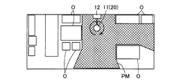
- the travel control unit 61 controls the driving of the driving wheel 21 (motor 33), so that the main body case 20 (the electric vacuum cleaner 11) rotates by a predetermined angle, for example, 360 ° (FIG. 5). . That is, in this embodiment, the vacuum cleaner 11 performs scanning on the spot without moving from the scanning start position.
- the turning operation is performed by, for example, the electric vacuum cleaner 11 (main body case) by causing the traveling control unit 61 to reverse one drive wheel 21 (motor 33) and the other drive wheel 21 (motor 33) with each other. 20) shall turn on the spot.
- the cleaning area excluding the position behind the object (obstacle) O when viewed from the electric vacuum cleaner 11 (main body case 20) can be acquired as the initial map PM.
- an additional scan is executed, and when a cleaning area that is a traveling place is further detected outside the initial map, the initial map is updated and expanded. That is, in the initial scan, for example, when furniture such as a sofa is arranged in the cleaning area, the position that is the shadow of the furniture viewed from the position of the vacuum cleaner 11 cannot be detected by the surrounding detection sensor 43. The cleaning area that could not be detected by the initial scan is reflected in the initial map by performing the additional scan.
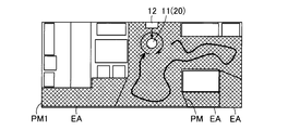
- the travel control unit 61 controls the drive of the drive wheels 21 (motor 33) within the range of the initial map PM created by the initial scan, so that the main body case 20 is moved.
- the vehicle is moved to a plurality of positions, and the travel control unit 61 controls the driving of the drive wheels 21 (motors 33) at the moved positions, respectively, while turning the main body case 20 respectively,
- the cleaning area which is the traveling location located outside the initial map PM, is confirmed.
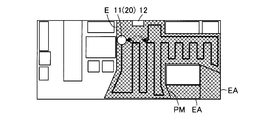
- the traveling control unit 61 controls the driving of the driving wheels 21 (motor 33) within the range of the initial map PM created by the initial scanning.
- the cleaning area EA located outside the initial map PM is confirmed by detecting the outer shape of the initial map PM by the surrounding detection sensor 43 while running 20 along the edge E of the initial map PM.
- the traveling control unit 61 controls the driving of the driving unit 21 (motor 33) within the range of the initial map PM created by the initial scanning, whereby the main body case 20
- the cleaning area EA located outside the initial map PM is confirmed by detecting the outer shape of the initial map PM by the surrounding detection sensor 43 while driving the vehicle.
- the vacuum cleaner 11 main body case 20
- the vacuum cleaner 11 is randomly traveled within the initial map PM, but may be traveled regularly, for example, in a zigzag shape.
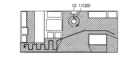
- the travel control unit 61 controls the drive of the drive wheels 21 (motor 33) in the vicinity of the edge E of the initial map PM created by the initial scan.
- the surrounding detection sensor 43 detects the outer shape of the initial map PM, thereby cleaning the outer position of the initial map PM.
- the position away from the current position is, for example, the position farthest away from the position of the vacuum cleaner 11 (main body case 20) or the second farthest position at the edge E of the initial map PM. .
- These operations are preferably selected from the product specifications such as the shape of the initial map PM and how to show the operation of the vacuum cleaner 11 to the user.For example, these operations can be combined with each other, and any plurality of operations can be performed. It can also be done sequentially.
- the map generation unit 64 detects the cleaning area EA outside the range of the initial map PM, the map generation unit 64 adds the cleaning area EA to the initial map PM and creates an updated initial map PM1.
- the initial map PM1 is stored in a memory provided in the control unit 24 or the like.
- the travel control unit 61 sets a travel route based on the initial map.
- the traveling route is set in the same manner as the above-described operation and control except for the separation operation from the charging device 12. That is, if the vacuum cleaner 11 is not connected to the charging device 12, it may be about to be transported to a different area from the previous cleaned area, such as a different floor. It is necessary to confirm whether it is the same as or different from the cleaning area. Therefore, in this case, the cleaning area is scanned using the surrounding detection sensor 43 as in the case where the vacuum cleaner 11 is connected to the charging device 12, and this scanning is performed when the map is not stored in the memory. If the map is stored in the memory, the map of the cleaning area and the self-location are confirmed by comparing the map with the initial map generated by scanning.
- the time estimation unit 65 estimates the cleaning time based on the map, and displays related to the estimated cleaning time on the display unit 25 by the display control unit 66.
- the traveling control unit 61 controls the driving wheel 21 (motor 33) to cause the body case 20 to autonomously travel along the traveling route set
- the cleaning control unit 62 operates the cleaning unit 22 in the cleaning area. Clean the floor (cleaning mode).
- the cleaning unit 22 for example, the dust on the floor surface is sucked by the electric blower 35, the brush motor 37 (rotary brush 36), or the side brush motor 39 (side brush 38) driven by the control unit 24 (cleaning control unit 62). It collects in the dust collecting part 40 through the mouth 31.
- the vacuum cleaner 11 detects the three-dimensional coordinates and position of an object such as an obstacle in the cleaning area that is not marked on the initial map by the surrounding detection sensor 43 and the infrared sensor 44 of the sensor unit 23 during autonomous traveling.
- the map generation unit 64 reflects it in the map and stores it in the memory (FIGS. 10 to 12).
- the control unit 24 determines the driving force of the electric blower 35, the rotating brush 36 (brush motor 37), or the side brush 38 (side brush motor 39) according to the amount of dust detected by the dust amount sensor 45 and the type of floor surface. It can be increased or decreased accordingly. For example, when the amount of dust detected by the dust amount sensor 45 is large, the driving force is increased, and when the amount of dust is relatively small, the driving force is decreased.
- the cleaning operation is terminated, and the electric vacuum cleaner 11 is returned to the charging device 12 by the travel control unit 61 controlling the drive of the drive wheel 21 (motor 33) (FIG. 13).
- the charging device 12 is connected (the charging terminal 71 and the charging terminal 73 are mechanically and electrically connected), and the charging operation is started at a predetermined timing such as a predetermined time after the connection.
- the control unit 24 determines whether or not the electric vacuum cleaner 11 is connected to the charging device 12 (step S1). If it is determined in step S1 that the charging device 12 is connected, the traveling control unit 61 controls the driving of the driving wheels 21 (motor 33) to charge the vacuum cleaner 11 (main body case 20). Detach from the device 12 (step S2). Thereafter, the map generation unit 64 determines whether or not a map is stored in the memory (step S3).
- the electric vacuum cleaner 11 controls the driving of the driving wheel 21 (motor 33) by the travel control unit 61 so that the electric vacuum cleaner 11 (main body case 20) has a predetermined value. While the initial motion (for example, turning) is performed, the surrounding detection sensor 43 scans the cleaning area by detecting the surrounding shape, and the map generation unit 64 generates an initial map (step S4). Next, in the vacuum cleaner 11, the travel detection unit 61 controls the driving of the drive wheel 21 (motor 33) to cause the vacuum cleaner 11 (main body case 20) to perform a predetermined operation, while the surrounding detection sensor 43 has a surrounding shape. Is detected, the cleaning area is additionally scanned, and the map generation unit 64 updates the initial map (step S5).
- step S1 when it is determined in step S1 that the charging device 12 is not connected, the vacuum cleaner 11 controls the driving of the driving wheel 21 (motor 33) by the travel control unit 61 (the vacuum cleaner 11 ( The surrounding detection sensor 43 detects the surrounding shape while causing the main body case 20) to perform a predetermined initial operation (for example, turning), thereby scanning the cleaning area (step S6). Then, the map generator 64 determines whether or not a map is stored in the memory (step S7). If it is determined in step S7 that no map is stored, the process proceeds to step S4. If it is determined that a map is stored, the map generation unit 64 compares the map with the surrounding shape detected by the scan in step S6.
- step S8 the self position is confirmed, that is, the current position is grasped (step S8), and the process proceeds to step S9.
- the obstacles arranged in the cleaning area may include, for example, a chair or the like whose position may not be constant, so in step S8, the map stored in the memory and step S6 If the surrounding shape detected by scanning is different from the surrounding shape, the map can be updated by reflecting it in the stored map.
- the time estimation unit 65 estimates the cleaning time based on the map and displays it on the display unit 25 (step S9), and the cleaning unit 22 cleans it (step S10).
- the map generation unit 64 updates the map (step S12), and the process proceeds to step S13. If it is necessary to change the travel route by updating the map, the travel control unit 61 resets the travel route.
- step S11 when it is determined in step S11 that no detection is made, it is determined whether or not the traveling control unit 61 has completed the traveling route, that is, whether or not cleaning has been completed (step S13). If it is determined in step S13 that the cleaning is not completed, the process returns to step S10. If it is determined that the cleaning is completed, the travel control unit 61 controls the driving of the drive wheels 21 (motor 33). Then, the electric vacuum cleaner 11 (main body case 20) is returned to the charging device 12 (step S14), and the cleaning is finished.
- the surrounding detection sensor 43 is controlled by causing the main body case 20 to perform a predetermined initial operation within a predetermined range by controlling the driving of the drive wheels 21 by the travel control unit 61.
- the initial map of the cleaning area created based on the surrounding shape scanned by there is a possibility that the entire area of the cleaning area has not been detected.
- a detailed initial map can be created. Accordingly, the setting of the travel route by the travel control unit 61 becomes more accurate according to the actual cleaning area, and the cleaning area can be cleaned more efficiently and thoroughly.
- the driving control unit 61 controls the driving wheel 21 to turn the main body case 20 at a plurality of positions, and the surrounding detection sensor 43 confirms the cleaning area outside the initial map. In this case, the accuracy of the initial map can be further improved.
- the map generation unit 64 controls the driving of the drive wheels 21 by the travel control unit 61 so that the main body case 20 travels along the edge of the initial map while cleaning the outside of the initial map.
- the map generation unit 64 controls the driving of the drive wheels 21 by the travel control unit 61 so that the main body case 20 travels along the edge of the initial map while cleaning the outside of the initial map.
- the map generation unit 64 controls the driving of the drive wheels 21 by the travel control unit 61, and confirms the cleaning area outside the initial map while causing the main body case 20 to travel within the range of the initial map.
- the vacuum cleaner 11 main body case 20 travels around the initial map so that the cleaning area outside the initial map can be easily confirmed.
- the map generation unit 64 controls the driving of the drive wheels 21 by the travel control unit 61 to cause the main body case 20 to travel to a position away from the current position at the edge of the initial map, and then to the outside of the initial map. When confirming the cleaning area, it can be easily confirmed whether or not there is a cleaning area beyond the edge of the initial map.
- the map generation unit 64 detects a cleaning area outside the initial map, the accuracy of the map can be further improved by updating the initial map.
- This second embodiment is the same as that in the first embodiment, after the initial map is created after the start of cleaning, and the travel route set based on this initial map without the operation of expanding (updating) this initial map. While cleaning along the road, the initial map is updated from time to time to complete the map. That is, in this embodiment, after the scan for creating the initial map (initial scan), the process directly shifts to the cleaning operation without performing an additional scan. In other words, in this embodiment, the time required for creating the initial map is reduced, cleaning is started early, and the map is updated as needed while cleaning. Therefore, in the second embodiment, step S5 of the flowchart shown in FIG. 14 of the first embodiment is omitted.
- the travel control unit 61 can arbitrarily set a travel route based on an initial map or a map stored in a memory.
- a travel route for traveling in a zigzag area in a cleanable area
- an initial map (Map) is divided into multiple areas, travel route for each area (area travel route), travel route from the current position of the initial map (map) to the nearest edge, and then travel route based on that position ( Near-distance travel route) is possible.
- the travel control unit 61 controls the drive of the drive wheels 21 (motor 33) so that the main body case 20 can be cleaned in the initial map PM (map) (disturbance area).
- Map map
- a route that can efficiently travel (clean) is set, such as a route with less contact with an object or a route that minimizes the number of times the same part is traveled repeatedly.
- the travel control unit 61 or the map generation unit 64 divides the initial map PM (map) into a plurality of regions A, and a zigzag travel route or the like for each region A.
- Set the travel route For example, when the remaining amount of the secondary battery is insufficient to travel and clean all the areas A of the initial map PM (map), the plurality of areas are based on the remaining amount of the secondary battery. It is also possible to set the travel route so that only a part of the area A is cleaned preferentially from A.
- the travel control unit 61 controls the driving of the drive wheel 21 (motor 33) in the vicinity of the edge E of the initial map PM (map).
- a travel route is set so as to travel, for example, in a zigzag manner in the cleaning area with the position as a base point.
- the position close to the current position is, for example, the position closest to the position of the vacuum cleaner 11 (main body case 20) or the second closest position at the edge E of the initial map PM (map).
- the travel control unit 61 can also reset the travel route by adding or correcting the travel route based on the updated map.
- the process immediately shifts to cleaning of the area where the initial map can be cleaned, so the time required for creating the initial map can be reduced. You can start cleaning early.
- the time required for the additional scanning may be wasted, so cleaning is started without performing additional scanning. This is more effective for cleaning efficiency.
- the capacity of the secondary battery required for additional scanning can be reduced, so the capacity of the secondary battery can also be used effectively.
- the traveling control unit 61 controls the driving of the drive wheels 21, and the cleaning unit 22 cleans while driving the main body case 20 within the range of the initial map.
- the cleanable area inside the initial map can be cleaned first, so the time required for cleaning can be shortened and the cleaning efficiency can be further improved.
- the traveling control unit 61 controls the driving of the drive wheels 21, and the main body case 20 is sequentially traveled for each divided area in the initial map while the cleaning unit 22 is driven.
- the initial map can be subdivided into a plurality of areas, and the vacuum cleaner 11 can be run efficiently.
- the travel control unit 61 controls the driving of the drive wheels 21 to move the main body case 20 to the nearest edge of the initial map, and within the range of the initial map. In the case where the cleaning unit 22 performs cleaning while traveling, the cleaning can be started early from the nearest edge.
- the travel route set by the travel control unit 61 can also be applied to the first embodiment.
- the map data is transmitted not only to the memory but also to the server via the data communication means via the network and stored, or transmitted to the external device and stored in the memory of the external device. It can be stored or displayed on an external device.
- the surrounding detection sensor 43 an arbitrary configuration for detecting the three-dimensional coordinates of an object such as a sensor using a laser in addition to the camera 51 can be applied.
- notification means not only the display section 25 that displays images and the like, but also, for example, voice output means (speaking section) that notifies by voice can be used.
- the travel control unit 61, the cleaning control unit 62, the sensor connection unit 63, the map generation unit 64, the time estimation unit 65, the display control unit 66, and the like are configured to be included in the control unit 24, but are separately provided. Or may be combined arbitrarily.
- the driving control unit 61 controls the driving of the driving wheels 21 to cause the main body case 20 to perform a predetermined initial operation within a predetermined range, thereby scanning by the surrounding detection sensor 43. Since the initial map of the cleaning area is created based on the surrounding shape, the travel route and the like can be easily and accurately set based on the initial map, and the cleaning efficiency can be improved. In addition, since the user can visually observe that the surroundings are scanned by a predetermined initial operation (turning) of the vacuum cleaner 11, the vacuum cleaner 11 is not cleaning the cleaning area in a dark cloud, but the cleaning area. It is possible to appeal to the user that the shape is recognized and cleaned.
- the travel control unit 61 turns the main body case 20 by controlling the driving of the drive wheels 21, so that the shape around the main body case 20 can be easily detected. And appealing to the user that the cleaning area is being scanned, the merchantability can be improved.
- the user can know the approximate cleaning time, and the merchantability can be further improved.
- a travel control method for a vacuum cleaner characterized by scanning a surrounding shape by performing a predetermined initial operation within a predetermined range and creating an initial map of a travel location based on the scan.
- the traveling case outside the initial map is confirmed by a surrounding detection sensor while the main body case is traveling along the edge of the initial map, according to any one of (1) to (3) A traveling control method for an electric vacuum cleaner.
- the main body case is traveled to a position away from the current position at the edge of the initial map, and then the travel location outside the initial map is confirmed by a surrounding detection sensor.
- the traveling control method for the electric vacuum cleaner according to any one of the above.
Landscapes
- Engineering & Computer Science (AREA)
- Physics & Mathematics (AREA)
- Radar, Positioning & Navigation (AREA)
- General Physics & Mathematics (AREA)
- Remote Sensing (AREA)
- Aviation & Aerospace Engineering (AREA)
- Automation & Control Theory (AREA)
- Mechanical Engineering (AREA)
- Computer Vision & Pattern Recognition (AREA)
- Multimedia (AREA)
- Electromagnetism (AREA)
- Control Of Position, Course, Altitude, Or Attitude Of Moving Bodies (AREA)
- Electric Vacuum Cleaner (AREA)
Abstract
Description
Claims (12)
- 本体ケースと、
この本体ケースを走行可能とする駆動部と、
この駆動部の駆動を制御することで前記本体ケースを自律走行させる走行制御手段と、
掃除をする掃除部と、
前記本体ケースの周囲の形状を検出する周囲検出センサと、
前記走行制御手段により前記駆動部の駆動を制御することで前記本体ケースに所定範囲内で所定の初期動作をさせることにより前記周囲検出センサによって走査した周囲の形状に基づいて走行場所の初期地図を作成するマッピング手段と
を具備したことを特徴とした電気掃除機。 - 走行制御手段は、マッピング手段により初期地図を作成する際、駆動部の駆動を制御することで本体ケースを旋回させる
ことを特徴とした請求項1記載の電気掃除機。 - マッピング手段は、走行制御手段により駆動部の駆動を制御することで本体ケースを複数の位置でそれぞれ旋回させつつ初期地図の外方の走行場所を周囲検出センサにより確認する
ことを特徴とした請求項2記載の電気掃除機。 - マッピング手段は、走行制御手段により駆動部の駆動を制御することで本体ケースを初期地図の縁部に沿って走行させつつ前記初期地図の外方の走行場所を周囲検出センサにより確認する
ことを特徴とした請求項1ないし3いずれか一記載の電気掃除機。 - マッピング手段は、走行制御手段により駆動部の駆動を制御することで本体ケースを初期地図の範囲内で走行させつつ前記初期地図の外方の走行場所を周囲検出センサにより確認する
ことを特徴とした請求項1ないし3いずれか一記載の電気掃除機。 - マッピング手段は、走行制御手段により駆動部の駆動を制御することで本体ケースを初期地図の縁部にて現在位置から離れた位置へ走行させた後、前記初期地図の外方の走行場所を周囲検出センサにより確認する
ことを特徴とした請求項1ないし3いずれか一記載の電気掃除機。 - マッピング手段は、初期地図の外方の走行場所を検出すると、この初期地図を更新する
ことを特徴とした請求項4ないし6いずれか一記載の電気掃除機。 - マッピング手段により初期地図を作成した後、走行制御手段が駆動部の駆動を制御して本体ケースをこの初期地図の範囲内で走行させつつ掃除部が掃除をする
ことを特徴とした請求項1ないし7いずれか一記載の電気掃除機。 - マッピング手段により初期地図を作成した後、走行制御手段が駆動部の駆動を制御して本体ケースをこの初期地図内の分割された領域毎に順次走行させつつ掃除部が掃除をする
ことを特徴とした請求項1ないし7いずれか一記載の電気掃除機。 - マッピング手段により初期地図を作成した後、走行制御手段が駆動部の駆動を制御して本体ケースをこの初期地図の最も近い縁部に移動させ、この初期地図の範囲内で走行させつつ掃除部が掃除をする
ことを特徴とした請求項1ないし7いずれか一記載の電気掃除機。 - マッピング手段は、走行制御手段により駆動部の駆動を制御して本体ケースを走行させて掃除部により掃除している間も初期地図を随時更新する
ことを特徴とした請求項8ないし10いずれか一記載の電気掃除機。 - 初期地図の大きさに基づいて掃除時間を推定して報知する報知手段を具備した
ことを特徴とした請求項1ないし11いずれか一記載の電気掃除機。
Priority Applications (3)
| Application Number | Priority Date | Filing Date | Title |
|---|---|---|---|
| CN201780069281.8A CN109922702B (zh) | 2016-11-09 | 2017-06-07 | 电清扫机 |
| GB1906015.1A GB2570240B (en) | 2016-11-09 | 2017-06-07 | Vacuum cleaner |
| US16/346,582 US20190254490A1 (en) | 2016-11-09 | 2017-06-07 | Vacuum cleaner and travel control method thereof |
Applications Claiming Priority (2)
| Application Number | Priority Date | Filing Date | Title |
|---|---|---|---|
| JP2016-219124 | 2016-11-09 | ||
| JP2016219124A JP6831213B2 (ja) | 2016-11-09 | 2016-11-09 | 電気掃除機 |
Publications (1)
| Publication Number | Publication Date |
|---|---|
| WO2018087952A1 true WO2018087952A1 (ja) | 2018-05-17 |
Family
ID=62110584
Family Applications (1)
| Application Number | Title | Priority Date | Filing Date |
|---|---|---|---|
| PCT/JP2017/021222 Ceased WO2018087952A1 (ja) | 2016-11-09 | 2017-06-07 | 電気掃除機 |
Country Status (6)
| Country | Link |
|---|---|
| US (1) | US20190254490A1 (ja) |
| JP (1) | JP6831213B2 (ja) |
| CN (1) | CN109922702B (ja) |
| GB (1) | GB2570240B (ja) |
| TW (1) | TWI653965B (ja) |
| WO (1) | WO2018087952A1 (ja) |
Cited By (1)
| Publication number | Priority date | Publication date | Assignee | Title |
|---|---|---|---|---|
| EP3825070B1 (en) | 2018-07-19 | 2023-09-20 | Ecovacs Robotics Co., Ltd. | Robot control method, robot and storage medium |
Families Citing this family (21)
| Publication number | Priority date | Publication date | Assignee | Title |
|---|---|---|---|---|
| JP6831210B2 (ja) * | 2016-11-02 | 2021-02-17 | 東芝ライフスタイル株式会社 | 電気掃除機 |
| KR102314539B1 (ko) * | 2017-06-09 | 2021-10-18 | 엘지전자 주식회사 | 인공지능 이동 로봇의 제어 방법 |
| CN107728615B (zh) * | 2017-09-26 | 2019-12-13 | 上海思岚科技有限公司 | 一种自适应区域划分的方法及系统 |
| GB2566959A (en) * | 2017-09-28 | 2019-04-03 | Black & Decker Inc | Robotic device |
| CN111212588B (zh) * | 2017-11-16 | 2021-07-13 | 千叶工业大学 | 自走式扫除机 |
| GB2575462B (en) * | 2018-07-10 | 2021-10-20 | Sony Interactive Entertainment Inc | Apparatus, system and method of controlling a robotic device |
| US11409306B2 (en) | 2018-08-14 | 2022-08-09 | Chiba Institute Of Technology | Movement robot |
| ES2951735T3 (es) | 2018-11-06 | 2023-10-24 | Nihon Business Data Proc Center Co Ltd | Robot de limpieza autopropulsado |
| JP2020099461A (ja) * | 2018-12-21 | 2020-07-02 | 日立グローバルライフソリューションズ株式会社 | 自律走行型掃除機 |
| JP7295657B2 (ja) * | 2019-02-26 | 2023-06-21 | 東芝ライフスタイル株式会社 | 自律走行体装置 |
| CN111759226B (zh) * | 2019-04-02 | 2022-12-20 | 青岛塔波尔机器人技术股份有限公司 | 扫地机器人控制方法和扫地机器人 |
| CN210931221U (zh) * | 2019-09-05 | 2020-07-07 | 北京石头世纪科技股份有限公司 | 密封结构及智能清洁设备 |
| KR102386699B1 (ko) * | 2019-10-29 | 2022-04-14 | 엘지전자 주식회사 | 청소기 및 그 제어방법 |
| JP7780245B2 (ja) * | 2019-10-30 | 2025-12-04 | 東芝ライフスタイル株式会社 | 電気掃除装置 |
| CN210998737U (zh) * | 2019-11-12 | 2020-07-14 | 上海肇观电子科技有限公司 | 移动机器人 |
| KR102743768B1 (ko) | 2019-11-12 | 2024-12-18 | 넥스트브이피유 (상하이) 코포레이트 리미티드 | 이동 로봇 |
| SG10201913873QA (en) * | 2019-12-30 | 2021-07-29 | Singpilot Pte Ltd | Sequential Mapping And Localization (SMAL) For Navigation |
| US11930993B2 (en) | 2020-02-10 | 2024-03-19 | Matic Robots, Inc. | Waste bag with absorbent dispersion sachet |
| DE102020212999A1 (de) * | 2020-10-15 | 2022-04-21 | BSH Hausgeräte GmbH | Verfahren zum Betrieb eines mobilen, selbstfahrenden Geräts |
| US20230414052A1 (en) * | 2022-06-24 | 2023-12-28 | Sharkninja Operating Llc | Surface treatment apparatus rotational speed indicator user interface |
| CN116687271A (zh) * | 2023-05-23 | 2023-09-05 | 西安建筑科技大学 | 一种地面垃圾智能检测及快速清扫系统及方法 |
Citations (4)
| Publication number | Priority date | Publication date | Assignee | Title |
|---|---|---|---|---|
| US20160052133A1 (en) * | 2014-07-30 | 2016-02-25 | Lg Electronics Inc. | Robot cleaning system and method of controlling robot cleaner |
| JP2016047141A (ja) * | 2014-08-27 | 2016-04-07 | 株式会社東芝 | 電気掃除機 |
| JP2016515311A (ja) * | 2013-01-18 | 2016-05-26 | アイロボット コーポレイション | 移動ロボットを備える環境管理システム及び移動ロボットを用いる方法 |
| JP2016120168A (ja) * | 2014-12-25 | 2016-07-07 | 株式会社東芝 | 電気掃除機 |
Family Cites Families (9)
| Publication number | Priority date | Publication date | Assignee | Title |
|---|---|---|---|---|
| JP4243594B2 (ja) * | 2005-01-31 | 2009-03-25 | パナソニック電工株式会社 | 清掃ロボット |
| CN102083352B (zh) | 2008-04-24 | 2014-10-15 | 艾罗伯特公司 | 用于机器人使能的移动产品的定位、位置控制和导航系统的应用 |
| TW201305761A (zh) | 2011-07-21 | 2013-02-01 | Ememe Robot Co Ltd | 自走機器人及其定位方法 |
| KR101984214B1 (ko) * | 2012-02-09 | 2019-05-30 | 삼성전자주식회사 | 로봇 청소기의 청소 작업을 제어하기 위한 장치 및 방법 |
| JP6132659B2 (ja) * | 2013-02-27 | 2017-05-24 | シャープ株式会社 | 周囲環境認識装置、それを用いた自律移動システムおよび周囲環境認識方法 |
| KR102093177B1 (ko) * | 2013-10-31 | 2020-03-25 | 엘지전자 주식회사 | 이동 로봇 및 그 동작방법 |
| KR101578882B1 (ko) | 2014-05-02 | 2015-12-18 | 에브리봇 주식회사 | 로봇 청소기 및 그 제어 방법 |
| JP6397663B2 (ja) * | 2014-06-18 | 2018-09-26 | シャープ株式会社 | 自走式電子機器 |
| JP6382688B2 (ja) * | 2014-11-06 | 2018-08-29 | 日立建機株式会社 | 地図生成装置 |
-
2016
- 2016-11-09 JP JP2016219124A patent/JP6831213B2/ja active Active
-
2017
- 2017-06-07 US US16/346,582 patent/US20190254490A1/en not_active Abandoned
- 2017-06-07 CN CN201780069281.8A patent/CN109922702B/zh active Active
- 2017-06-07 WO PCT/JP2017/021222 patent/WO2018087952A1/ja not_active Ceased
- 2017-06-07 GB GB1906015.1A patent/GB2570240B/en active Active
- 2017-07-04 TW TW106122327A patent/TWI653965B/zh not_active IP Right Cessation
Patent Citations (4)
| Publication number | Priority date | Publication date | Assignee | Title |
|---|---|---|---|---|
| JP2016515311A (ja) * | 2013-01-18 | 2016-05-26 | アイロボット コーポレイション | 移動ロボットを備える環境管理システム及び移動ロボットを用いる方法 |
| US20160052133A1 (en) * | 2014-07-30 | 2016-02-25 | Lg Electronics Inc. | Robot cleaning system and method of controlling robot cleaner |
| JP2016047141A (ja) * | 2014-08-27 | 2016-04-07 | 株式会社東芝 | 電気掃除機 |
| JP2016120168A (ja) * | 2014-12-25 | 2016-07-07 | 株式会社東芝 | 電気掃除機 |
Cited By (2)
| Publication number | Priority date | Publication date | Assignee | Title |
|---|---|---|---|---|
| EP3825070B1 (en) | 2018-07-19 | 2023-09-20 | Ecovacs Robotics Co., Ltd. | Robot control method, robot and storage medium |
| US12186911B2 (en) | 2018-07-19 | 2025-01-07 | Ecovacs Robotics Co., Ltd. | Robot control method, robot and storage medium |
Also Published As
| Publication number | Publication date |
|---|---|
| TW201817361A (zh) | 2018-05-16 |
| JP6831213B2 (ja) | 2021-02-17 |
| GB2570240B (en) | 2022-04-20 |
| TWI653965B (zh) | 2019-03-21 |
| CN109922702A (zh) | 2019-06-21 |
| US20190254490A1 (en) | 2019-08-22 |
| JP2018075191A (ja) | 2018-05-17 |
| CN109922702B (zh) | 2021-07-09 |
| GB2570240A (en) | 2019-07-17 |
| GB201906015D0 (en) | 2019-06-12 |
Similar Documents
| Publication | Publication Date | Title |
|---|---|---|
| JP6831213B2 (ja) | 電気掃除機 | |
| JP6685755B2 (ja) | 自律走行体 | |
| CN110325938B (zh) | 电动吸尘器 | |
| JP7058067B2 (ja) | 自律走行体 | |
| CN109843139B (zh) | 电动吸尘器 | |
| CN109891348B (zh) | 自主行走体 | |
| JP7007078B2 (ja) | 電気掃除機 | |
| JP7141220B2 (ja) | 自走式電気掃除機 | |
| KR101840158B1 (ko) | 전기청소기 | |
| CN110325089B (zh) | 电动吸尘器 | |
| JP6864433B2 (ja) | 電気掃除機 | |
| CN110636789B (zh) | 电动吸尘器 | |
| JP6912937B2 (ja) | 電気掃除機 |
Legal Events
| Date | Code | Title | Description |
|---|---|---|---|
| 121 | Ep: the epo has been informed by wipo that ep was designated in this application |
Ref document number: 17870178 Country of ref document: EP Kind code of ref document: A1 |
|
| ENP | Entry into the national phase |
Ref document number: 201906015 Country of ref document: GB Kind code of ref document: A Free format text: PCT FILING DATE = 20170607 |
|
| NENP | Non-entry into the national phase |
Ref country code: DE |
|
| 122 | Ep: pct application non-entry in european phase |
Ref document number: 17870178 Country of ref document: EP Kind code of ref document: A1 |