WO2018084018A1 - 電子制御装置及び通信機器 - Google Patents
電子制御装置及び通信機器 Download PDFInfo
- Publication number
- WO2018084018A1 WO2018084018A1 PCT/JP2017/038270 JP2017038270W WO2018084018A1 WO 2018084018 A1 WO2018084018 A1 WO 2018084018A1 JP 2017038270 W JP2017038270 W JP 2017038270W WO 2018084018 A1 WO2018084018 A1 WO 2018084018A1
- Authority
- WO
- WIPO (PCT)
- Prior art keywords
- current
- wiring
- bus
- control device
- electronic control
- Prior art date
- Legal status (The legal status is an assumption and is not a legal conclusion. Google has not performed a legal analysis and makes no representation as to the accuracy of the status listed.)
- Ceased
Links
Images

Classifications
-
- G—PHYSICS
- G06—COMPUTING OR CALCULATING; COUNTING
- G06F—ELECTRIC DIGITAL DATA PROCESSING
- G06F13/00—Interconnection of, or transfer of information or other signals between, memories, input/output devices or central processing units
- G06F13/14—Handling requests for interconnection or transfer
- G06F13/20—Handling requests for interconnection or transfer for access to input/output bus
- G06F13/22—Handling requests for interconnection or transfer for access to input/output bus using successive scanning, e.g. polling
-
- G—PHYSICS
- G06—COMPUTING OR CALCULATING; COUNTING
- G06F—ELECTRIC DIGITAL DATA PROCESSING
- G06F13/00—Interconnection of, or transfer of information or other signals between, memories, input/output devices or central processing units
- G06F13/14—Handling requests for interconnection or transfer
- G06F13/36—Handling requests for interconnection or transfer for access to common bus or bus system
- G06F13/368—Handling requests for interconnection or transfer for access to common bus or bus system with decentralised access control
- G06F13/37—Handling requests for interconnection or transfer for access to common bus or bus system with decentralised access control using a physical-position-dependent priority, e.g. daisy chain, round robin or token passing
-
- H—ELECTRICITY
- H04—ELECTRIC COMMUNICATION TECHNIQUE
- H04L—TRANSMISSION OF DIGITAL INFORMATION, e.g. TELEGRAPHIC COMMUNICATION
- H04L12/00—Data switching networks
- H04L12/28—Data switching networks characterised by path configuration, e.g. LAN [Local Area Networks] or WAN [Wide Area Networks]
- H04L12/40—Bus networks
-
- H—ELECTRICITY
- H04—ELECTRIC COMMUNICATION TECHNIQUE
- H04L—TRANSMISSION OF DIGITAL INFORMATION, e.g. TELEGRAPHIC COMMUNICATION
- H04L25/00—Baseband systems
- H04L25/02—Details ; arrangements for supplying electrical power along data transmission lines
-
- H—ELECTRICITY
- H04—ELECTRIC COMMUNICATION TECHNIQUE
- H04L—TRANSMISSION OF DIGITAL INFORMATION, e.g. TELEGRAPHIC COMMUNICATION
- H04L41/00—Arrangements for maintenance, administration or management of data switching networks, e.g. of packet switching networks
- H04L41/06—Management of faults, events, alarms or notifications
- H04L41/0677—Localisation of faults
-
- H—ELECTRICITY
- H04—ELECTRIC COMMUNICATION TECHNIQUE
- H04L—TRANSMISSION OF DIGITAL INFORMATION, e.g. TELEGRAPHIC COMMUNICATION
- H04L43/00—Arrangements for monitoring or testing data switching networks
- H04L43/08—Monitoring or testing based on specific metrics, e.g. QoS, energy consumption or environmental parameters
- H04L43/0805—Monitoring or testing based on specific metrics, e.g. QoS, energy consumption or environmental parameters by checking availability
- H04L43/0817—Monitoring or testing based on specific metrics, e.g. QoS, energy consumption or environmental parameters by checking availability by checking functioning
-
- H—ELECTRICITY
- H04—ELECTRIC COMMUNICATION TECHNIQUE
- H04L—TRANSMISSION OF DIGITAL INFORMATION, e.g. TELEGRAPHIC COMMUNICATION
- H04L12/00—Data switching networks
- H04L12/28—Data switching networks characterised by path configuration, e.g. LAN [Local Area Networks] or WAN [Wide Area Networks]
- H04L12/40—Bus networks
- H04L2012/40208—Bus networks characterized by the use of a particular bus standard
- H04L2012/40215—Controller Area Network CAN
-
- H—ELECTRICITY
- H04—ELECTRIC COMMUNICATION TECHNIQUE
- H04L—TRANSMISSION OF DIGITAL INFORMATION, e.g. TELEGRAPHIC COMMUNICATION
- H04L12/00—Data switching networks
- H04L12/28—Data switching networks characterised by path configuration, e.g. LAN [Local Area Networks] or WAN [Wide Area Networks]
- H04L12/40—Bus networks
- H04L2012/40267—Bus for use in transportation systems
- H04L2012/40273—Bus for use in transportation systems the transportation system being a vehicle
Definitions
- the present invention relates to an electronic control device and a communication device.
- actuators and sensors are abbreviated as actuators and the like.
- the conventional method of replacing the direct connection between the host ECU and the actuator with separate wiring is replaced with a common bus wiring.
- a technique of transmitting and receiving information by designating a transmission source and a transmission destination with an ID assigned to each ECU is effective.
- an electronic control device hereinafter referred to as a subordinate ECU having a communication function is also required on the side of the actuator or the like.
- bus wiring is a connection form in which a plurality of electronic control devices are connected to a common wiring. This connection mode is characterized in that a signal transmitted from one ECU is received by all other ECUs.
- the bus wiring method has a merit that the weight and cost of the wire harness can be reduced because the number and structure of wiring are simpler than the conventional direct connection method.
- connection location automatic detection method an example as shown in Patent Document 1 is known.
- a method for determining a connection location in this patent document, “position with respect to each other” based on the time taken for another device to measure a signal transmitted by one of the devices in the network is presented. ing.
- Patent Document 1 has a problem that a high time measurement resolution is required when the distance between the apparatuses is short.
- a signal propagates at a speed of about 200,000 km per second. Therefore, for example, when a resolution for detecting a connection place of 10 cm in both directions is required, a time measurement resolution of about 1 nanosecond is required.
- a counter circuit or the like that operates at high speed is required, which causes a problem of increasing costs.
- An object of the present invention is to provide an electronic control device and the like that can identify the order of communication devices connected to a bus while suppressing manufacturing costs.
- the present invention provides a first port to which one end of a bus to which a plurality of communication devices are connected is connected, a second port to which the other end of the bus is connected, and the plurality of communications.
- a current sensor for measuring a first current value of a current flowing through the first port and a second current value of a current flowing through the second port when each of the devices applies a current to the bus; and the plurality of communication devices
- a controller that identifies the order of the plurality of communication devices on the bus based on the first current value and the second current value measured for each of the first and second current values.
- connection composition such as an electronic control unit by a 1st embodiment. It is a graph showing the relationship between the connection position of low-order ECU and the detected electric current in high-order ECU in 1st Embodiment. It is a circuit block diagram showing the structure of the low-order ECU by a modification. It is a circuit block diagram showing connection composition, such as an electronic controller by a 2nd embodiment. It is a circuit block diagram showing connection composition, such as an electronic control unit by a 3rd embodiment. It is the figure which showed typically the system before identifying the order of low-order ECU. It is a figure which shows the table which memorize
- an object of the embodiment of the present invention is, for example, a host ECU that can automatically and accurately measure the connection position of a lower ECU without using a circuit that requires high-speed operation. (Electronic control device), or to provide an actuator or sensor provided with a subordinate ECU (communication device).
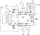
- the system 100 includes a host ECU 1 (electronic control device), bus wiring 2, and a plurality of lower ECUs 301 to 304 (communication devices).
- ECU 1 electronic control device
- bus wiring 2 bus wiring 2
- ECUs 301 to 304 communication devices
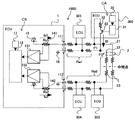
- the host ECU 1 is connected to the bus wiring 2 through two ports 111 and 112, and the interior is composed of a host controller 12, amplifiers 131 and 132, current detection resistors 141 and 142, a power source 15 of voltage Vb, and GND 16. Is done.
- the amplifier 131 amplifies the voltage (the voltage across the current detection resistor 141) obtained by converting the current Is1 flowing through the port 111 by the current detection resistor 141, and inputs the amplified voltage to the host controller 12.
- the amplifier 132 amplifies the voltage obtained by converting the current Is2 flowing through the port 112 by the current detection resistor 142 and inputs the amplified voltage to the host controller 12.
- the host controller 12 measures, for example, the connection location of the target lower ECU 302 from the currents Is1 and Is2 thus detected. This measuring method will be described later.
- the bus wiring 2 is composed of two wirings, that is, a power supply side (high side) wiring 21 and a GND side (low side) wiring 22, and is connected to the host ECU 1 via ports 111 and 112. It has a form. Further, the bus wiring 2 is also connected to the lower ECUs 301 to 304 in the middle thereof. These wirings have wiring resistance 23, and the value is proportional to the length of the wiring.
- bus wiring 2 (bus) is connected to the port 111 (first port), and the other end of the bus wiring 2 is connected to the port 112 (second port).
- a plurality of lower-level ECUs 301 to 304 (communication devices) are connected to the bus wiring 2.
- the lower ECUs 301 to 304 are connected to the bus wiring 2, and the interior thereof includes a lower controller 31, a load resistor 32, and a switch 33.
- the lower controller 31 can receive a command from the upper controller 12 by a predetermined communication method (protocol), turn on the switch 33 at an arbitrary timing, and allow the measurement current I0 to flow through the bus wiring 2.
- the bus wiring 2 (bus) includes a wiring 21 (first wiring) and a wiring 22 (second wiring).
- the load resistor 32 (resistor), the switch 33, and the low-order controller 31 constitute a current application device CA.
- the load resistor 32 and the switch 33 are connected in series between the wiring 21 and the wiring 22.
- the lower controller 31 (controller) turns on the switch 33 when receiving a command to apply a current to the bus wiring 2.
- the current application device CA when the current application device CA receives a command to apply a current to the bus wiring 2, the current application device CA changes the impedance between the wiring 21 and the wiring 22 and causes the current to flow between the wiring 21 and the wiring 22.
- the upper controller 12 and the lower controller 31 include a processor, a RAM, a ROM, an input circuit to which a signal is input via the bus wiring 2, an output circuit for outputting a signal via the bus wiring 2, and the like.
- connection location Next, a method for measuring the connection location will be described. Here, an example of measuring the connection location of the lower ECU 302 among the plurality of lower ECUs will be described.
- the lower ECU 302 can receive a command from the upper controller 12 and cause the measurement current I0 to flow through the bus wiring 2.
- Currents Is1 and Is2 obtained by dividing the measurement current I0 by wiring resistance or the like are measured by the host ECU 1, and the connection location is measured from these relationships.
- the host controller 12 transmits a command to apply a current to the bus wiring 2 (bus) to each of the plurality of lower ECUs 301 to 304 (communication devices).
- the current detection resistors 141 and 142, the amplifiers 131 and 132, and the host controller 12 constitute a current sensor CS.
- the current sensor CS includes a current Is1 (first current value) flowing through the port 111 (first port) and a port 112 (second port) when each of the plurality of lower-level ECUs 301 to 304 applies a current to the bus wiring 2.
- the flowing current Is2 (second current value) is measured.
- the host controller 12 identifies the order of the plurality of lower ECUs 301 to 304 on the bus wiring 2 based on the current Is1 and the current Is2 measured for each of the plurality of lower ECUs 301 to 304.
- connection location between I0 and the lower ECU 302 and the relationship between Is1 and Is2 will be described.
- the wiring resistance per port from the port 111 to the connection portion (connection points P1, P2) of the lower ECU 302 is Rw1
- the wiring resistance Rw2 per port from the port 112 to the connection portion of the lower ECU 302 Is1 and Is2
- Is1 and Is2 The value is represented by equations 1 and 2.
- the host controller 12 determines the difference between the current Is1 (first current value) and the current Is2 (second current value) measured for each of the plurality of lower ECUs 301 to 304 (communication devices), and the current. Based on the ratio of Is1 and the sum of current Is2, the order of the plurality of lower-level ECUs 301 to 304 on the bus wiring 2 (bus) is identified.
- connection position measurement is to determine which actuator, etc., each sub-ECU is in charge of, as described in the paragraph “Bus wiring and its problems”. This is because it is sufficient if the order of the connection positions (the relationship of the distance from each port of the host ECU 1) can be identified.
- the current sensor CS measures the current using the current detection resistors 141 and 142 (shunt resistors), and the resistance value of the current detection resistors 141 and 142 is changed from the port 111 (first port) to the port 112. It is smaller than the resistance value of the bus wiring 2 (bus) up to (second port).
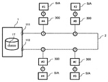
- FIG. 6 is a diagram schematically showing a system before identifying the order of the lower ECUs.
- One upper ECU 1 and four lower ECUs 300 are connected to the bus wiring 2.
- a sensor or an actuator (hereinafter abbreviated as S / A) is connected to each of the lower ECUs 300.
- the upper ECU 1 can communicate with the lower ECU 300 using the ID (identifier) of the lower ECU 300. However, it is initially unknown where the lower ECU 300 corresponding to each ID is connected.
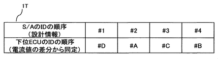
- FIG. 7 is a diagram showing a table 1T provided in a non-volatile memory (for example, a flash memory built in the host controller 12) of the host ECU 1.
- the first record of the table 1T stores the order of S / A IDs as design information.
- the S / A having the ID of # 1 is connected to the first subordinate ECU 300 in the order from the port 111 of the bus wiring 2 to the second subordinate ECU 300. Is connected to the S / A having the ID of # 2, the S / A having the ID of # 3 is connected to the third lower ECU 300, and the S / A having the ID of # 4 is connected to the fourth lower ECU 300. Indicates that it is connected.
- the host ECU 1 identifies the order of the four lower ECUs 300 on the bus wiring 2 by arranging the current value differences (Is1-Is2) measured for the respective lower ECUs 300 in descending order. Then, the upper ECU 1 stores the ID order of the lower ECU 300 as the second record of the table 1T.
- the ID of the first lower ECU 300 is #D
- the ID of the second lower ECU 300 is #A in order from the port 111 of the bus wiring 2.
- the ID of the third subordinate ECU 300 is #C
- the ID of the fourth subordinate ECU 300 is #B.
- the upper ECU 1 compares the first record and the second record of the table 1T, and as shown in FIG. 8, the #D S / A is connected to the #D lower ECU 300, and the #A lower ECU 300 # 2
- the S / A of # 3 is connected, the S / A of # 3 is connected to the subordinate ECU 300 of #C, and the S / A of # 4 is connected to the subordinate ECU 300 of #B.
- the current detection resistors 141 and 142 are used to detect the current at each port.
- another form of current detection means may be used.
- the same effect can be obtained even if a Hall sensor type current sensor is used.
- the main purpose of the embodiment of the present invention is to determine which actuator or the like each sub-ECU is responsible for, but the connection position measurement is continued during the operation of the system 100. By doing so, it is also possible to diagnose the presence or absence of abnormality in the lower control device and the wiring from the presence or absence of the change. This is because it can be determined that some abnormality has occurred in the subordinate control device or wiring if the measurement result of the connection position has changed significantly even though the connection position and wiring configuration have not been changed.
- the host controller 12 (controller) has a current Is1 (first current value) and a current Is2 (second current) measured for a target communication device that is one of the plurality of lower ECUs 301 to 304 (communication devices).
- the current value changes with time, it is determined that a failure has occurred in the target communication device or the bus wiring 2 (bus).
- the host controller 12 determines that a failure has occurred, the host controller 12 notifies that the failure has occurred, for example, by turning on a warning lamp.
- the load resistor 32 and the switch 33 are connected in series as a means for flowing the measurement current I0.
- the MOSFET 33a may be saturated so that a desired measurement current I0 flows.
- the current application device CA includes a MOSFET 33a and a lower controller 31 (controller).
- the MOSFET 33 a is connected between the wiring 21 and the wiring 22.
- the lower controller 31 receives a command to apply a current to the bus wiring 2 (bus)
- the lower controller 31 controls the gate voltage of the MOSFET 33a to saturate the MOSFET 33a.
- the manufacturing cost can be reduced.
- the mounting means is not limited to the above-described mounting means as long as the current flows by changing the impedance between the wirings 21 and 22.
- bus wiring 2 is shown as an example composed of two wirings, but may be composed of three or more wirings.
- the configuration of the system 100A in the present embodiment is the same as that in the first embodiment except that the lower ECUs 301 to 304 include the lower ECU internal power supply 34.
- the load resistor 32 resistor
- the load resistor 32 is connected to the lower ECU internal power supply 34 (internal power supply).
- the impedance between the wirings 21 and 22 is changed to flow the measurement current I0 in the first embodiment, whereas in this embodiment, the impedance between the lower ECU internal power supply 34 and the wiring 22 is changed. Is the same as that of the first embodiment except that the measurement current I0 is caused to flow by changing.
- This embodiment is effective when the power supply voltage at which the lower ECUs 301 to 304 operate and the voltage of the power supply 15 of the upper ECU 1 are different.
- the configuration of the system 100B in this embodiment is the same as that in the first embodiment except that the pattern generators 17 and 35 are connected to the upper controller 12 and the lower controller 31, respectively, in addition to the configuration in the first embodiment.
- the configuration is the same.
- the operation of the electronic control device and the like in the present embodiment will be described mainly for the differences from the first embodiment.
- the pattern generators 17 and 35 both generate the same time series pattern with high autocorrelation.
- the lower controller 31 switches ON / OFF of the switch 33 according to the pattern given from the pattern generator 35. As a result, the measurement current I0 is modulated with the pattern. Then, the upper controller 12 demodulates the detection values of Is1 and Is2 into which I0 is divided according to the pattern given from the pattern generator 17, and the connection location of the target lower ECU 302 based on the magnitudes of the demodulation values of Is1 and Is2. Measure.
- each of the plurality of lower-level ECUs 301 to 304 includes a pattern generator 35 that generates a time series pattern with high autocorrelation.
- the lower controller 31 controls the lower controller 31 (controller) turns on / off the switch 33 according to the time-series pattern generated by the pattern generator 35.
- the host ECU 1 as an electronic control device includes a pattern generator 17 that generates a time-series pattern with high autocorrelation.
- the host controller 12 demodulates the current Is1 (first current value) and the current Is2 (second current value) according to the time series pattern generated by the pattern generator 17.
- the present embodiment can improve resistance to noise as compared with the first embodiment.
- M series Maximum length sequence
- a Gold sequence derived from the M sequence is also useful.
- a similar purpose can be achieved if the sequence has a high autocorrelation.
- the present invention is not limited to the above-described embodiment, and includes various modifications.
- the above-described embodiment has been described in detail for easy understanding of the present invention, and is not necessarily limited to the one having all the configurations described.
- a part of the configuration of an embodiment can be replaced with the configuration of another embodiment, and the configuration of another embodiment can be added to the configuration of an embodiment.
- each of the above-described configurations, functions, and the like may be realized by hardware by designing a part or all of them with, for example, an integrated circuit.
- each of the above-described configurations, functions, and the like may be realized by software by interpreting and executing a program that realizes each function by a processor (controller).
- Information such as programs, tables, and files for realizing each function can be stored in a recording device such as a memory, a hard disk, or an SSD (Solid State Drive), or a recording medium such as an IC card, an SD card, or a DVD.
- An electronic control device that is connected to a plurality of lower-level control devices by bus-like wiring and has two or more wiring connection ports, and means for detecting a wiring current at each of the wiring connection ports.
- An electronic control device characterized in that a position on a wiring of the specific lower control device is measured from a relationship between two detection values at each connection port of a current applied by the lower control device.
- the number of the wiring connection ports is two, and the two are connected in a loop with a bus-like wiring. .
- the relationship between the two detection values is a difference between the two detection values.
- the relationship between the two detection values is a value obtained by dividing a difference between the two detection values by a sum of the two detection values.
- a shunt resistance method is used for current detection at each connection port, and the resistance value of the shunt resistance is smaller than the total wiring resistance value of the bus wiring.
- the means for applying a current in the lower control device is configured to change an impedance between wirings of the bus-like wiring.
- the means for changing the impedance is configured by configuring a resistor and a switch in series.
- the means for changing the impedance is constituted by a MOSFET, and the MOSFET is saturated when a current is applied.
- the means for applying a current in the subordinate control device is configured to apply a current from an internal power supply of the subordinate control device.
- Electronic control device characterized.
- connection position of the low-order ECU can be measured automatically and with high resolution without using a circuit that operates at high speed.
- An actuator and a sensor provided with the same can be provided.
Landscapes
- Engineering & Computer Science (AREA)
- Computer Networks & Wireless Communication (AREA)
- Signal Processing (AREA)
- Theoretical Computer Science (AREA)
- Environmental & Geological Engineering (AREA)
- Physics & Mathematics (AREA)
- General Engineering & Computer Science (AREA)
- General Physics & Mathematics (AREA)
- Power Engineering (AREA)
- Arrangements For Transmission Of Measured Signals (AREA)
- Small-Scale Networks (AREA)
- Dc Digital Transmission (AREA)
Abstract
本発明は、製造コストを抑制しつつ、バスに接続される通信機器の順序を同定することができる電子制御装置等を提供する。本発明では、ポート111には、バス配線2の一端が接続され、ポート112にはバス配線2の他端が接続される。バス配線2には、複数の下位ECU301~304が接続される。電流センサCSは、複数の下位ECU301~304のそれぞれがバス配線2に電流を印加することによりポート111に流れる電流Is1及びポート112に流れる電流Is2をそれぞれ測定する。上位コントローラ12は、複数の下位ECU301~304のそれぞれに対して測定された電流Is1と電流Is2に基づいて、複数の下位ECU301~304のバス配線2上の順序を同定する。
Description
本発明は、電子制御装置及び通信機器に関する。
[省配線化への要求]
近年の自動車の高機能化は著しく、それに伴って車両に搭載されるアクチュエータやセンサの数が増加している。それに伴い、上位の電子制御装置(以下、上位ECU)、例えばエンジン制御ECUとアクチュエータやセンサ(例えば燃料噴射装置)との間を接続するワイヤハーネスの重量およびコストも増大している。これに対し、燃費改善等のための軽量化要求から、ワイヤハーネスを省配線化したいという要求が強まっている。以下、アクチュエータやセンサをアクチュエータ等と略して記述する。
近年の自動車の高機能化は著しく、それに伴って車両に搭載されるアクチュエータやセンサの数が増加している。それに伴い、上位の電子制御装置(以下、上位ECU)、例えばエンジン制御ECUとアクチュエータやセンサ(例えば燃料噴射装置)との間を接続するワイヤハーネスの重量およびコストも増大している。これに対し、燃費改善等のための軽量化要求から、ワイヤハーネスを省配線化したいという要求が強まっている。以下、アクチュエータやセンサをアクチュエータ等と略して記述する。
上位のECUとアクチュエータ等との接続に用いられるワイヤハーネスの省配線化手法としては、従来は上位ECUとアクチュエータ等との間とを個別の配線で直結していたものを共通のバス配線で置き換え、各ECUに割り当てられたID等で送信元や送信先を指定して情報を送受信する形とする手法が効果的である。このとき、アクチュエータ等の側にも通信機能を備える電子制御装置(以下、下位ECU)が必要となる。
[バス配線とその課題]
上述の「バス配線」は、共通の配線に対して複数の電子制御装置を接続する接続形態である。本接続形態では、1つのECUが送信した信号は他の全てのECUで受信されるという特徴がある。バス配線方式は、従来の直結方式と比べて配線の本数および構造が単純となるため、ワイヤハーネスの重量およびコストを軽減できるメリットがある。
上述の「バス配線」は、共通の配線に対して複数の電子制御装置を接続する接続形態である。本接続形態では、1つのECUが送信した信号は他の全てのECUで受信されるという特徴がある。バス配線方式は、従来の直結方式と比べて配線の本数および構造が単純となるため、ワイヤハーネスの重量およびコストを軽減できるメリットがある。
一方で、バス配線方式にはデメリットも存在する。信号が全ての下位ECUに届くため、上位ECUから見て、通信している下位ECUがどのアクチュエータ等を担当しているのか(例えば、燃料噴射装置であれば何番目の気筒に取り付けられているのか。以下、接続場所と記載する)が区別できないというデメリットである。従来の直結方式であれば、ワイヤハーネスを作成する際に接続場所と上位ECU側の接続ポート番号が一意に対応していたため、この問題は生じなかった。
バス配線方式でも、一つの解決方法として、IDと接続場所とを組み立て時に対応させる手法が考えられる。しかし、この方式は組み立て工数の増大や組み合わせ情報の入力ミスのリスクといったデメリットが存在し、低コストで高信頼なシステムを実現するのが困難となる。
これを解決するには接続場所を自動的に検出する手法が必要である。このような接続場所自動検出手法として、特許文献1に示されているような例が知られている。本特許文献では、ネットワーク中の装置の1つが送信した信号を他の装置が測定するのにかかる時間に基づき、接続場所(本特許文献中では「お互いに対する位置」)を決定する手法が提示されている。
一方で、特許文献1に示された手法は、装置同士の距離が短い場合に高い時間測定分解能が必要になるという課題がある。一般的に有線通信において信号は20万km毎秒前後の速度で伝搬するため、例えば往復10cmの接続場所検出の分解能が必要な場合、1ナノ秒程度の時間測定分解能が必要となる。これを実現するには高速に動作するカウンタ回路などが必要となり、コスト増要因となってしまうという課題がある。
このため、従来、製造コストを抑制しつつ、バスに接続される下位ECU(通信機器)の順序を同定することができなかった。
本発明の目的は、製造コストを抑制しつつ、バスに接続される通信機器の順序を同定することができる電子制御装置等を提供することにある。
上記目的を達成するために、本発明は、複数の通信機器が接続されるバスの一端が接続される第1ポートと、前記バスの他端が接続される第2ポートと、前記複数の通信機器のそれぞれが前記バスに電流を印加することにより前記第1ポートに流れる電流の第1電流値及び前記第2ポートに流れる電流の第2電流値を測定する電流センサと、前記複数の通信機器のそれぞれに対して測定された前記第1電流値と前記第2電流値に基づいて、前記複数の通信機器の前記バス上の順序を同定するコントローラと、を備える。
本発明によれば、製造コストを抑制しつつ、バスに接続される通信機器の順序を同定することができる。上記した以外の課題、構成及び効果は、以下の実施形態の説明により明らかにされる。
以下、図面を用いて、本発明の第1~第3の実施形態による電子制御装置等の構成及び動作について説明する。
前述した目的と一部重複するが、本発明の実施形態の目的は、例えば、高速動作が必要な回路を用いることなく下位ECUの接続位置を自動的かつ高い分解能で測定することができる上位ECU(電子制御装置)、もしくは下位ECU(通信機器)を備えたアクチュエータまたはセンサを提供することにある。
(第1の実施形態)
[全体構成]
本発明の第1の実施形態による電子制御装置を含むシステム100の構成と動作について、図1を用いて説明する。システム100は、上位ECU1(電子制御装置)と、バス配線2と、複数の下位ECU301~304(通信機器)から構成される。
[全体構成]
本発明の第1の実施形態による電子制御装置を含むシステム100の構成と動作について、図1を用いて説明する。システム100は、上位ECU1(電子制御装置)と、バス配線2と、複数の下位ECU301~304(通信機器)から構成される。
上位ECU1は、バス配線2と2か所のポート111および112で接続され、その内部は上位コントローラ12、アンプ131および132、電流検出抵抗器141および142、電圧Vbの電源15、およびGND16から構成される。
アンプ131はポート111に流れる電流Is1が電流検出抵抗器141により変換された電圧(電流検出抵抗器141の両端電圧)を増幅し、上位コントローラ12に入力する。同様に、アンプ132はポート112に流れる電流Is2が電流検出抵抗器142により変換された電圧を増幅し、上位コントローラ12に入力する。
上位コントローラ12はこのように検出された電流Is1およびIs2から、例えば、対象とする下位ECU302の接続場所を測定する。この測定方法については後述する。
バス配線2は2本の配線、すなわち電源側(ハイサイド)の配線21、およびGND側(ローサイド)の配線22から構成され、上位ECU1に対してポート111および112で接続され、ループ状の配線形態となっている。また、バス配線2は、その途中で下位ECU301~304とも接続されている。これらの配線は配線抵抗23をもち、その値は配線の長さに比例する。
換言すれば、ポート111(第1ポート)には、バス配線2(バス)の一端が接続され、ポート112(第2ポート)にはバス配線2の他端が接続される。バス配線2には、複数の下位ECU301~304(通信機器)が接続される。
下位ECU301~304は、バス配線2と接続され、その内部は下位コントローラ31、負荷抵抗32、およびスイッチ33から構成される。下位コントローラ31は所定の通信手法(プロトコル)により、上位コントローラ12からの指令を受け、任意のタイミングでスイッチ33をONし、測定用電流I0をバス配線2に流すことができる。
換言すれば、バス配線2(バス)は、配線21(第1配線)と配線22(第2配線)を含む。負荷抵抗32(抵抗器)、スイッチ33、下位コントローラ31は、電流印加装置CAを構成する。負荷抵抗32及びスイッチ33は、配線21と配線22の間に直列接続される。下位コントローラ31(コントローラ)は、バス配線2に電流を印加する指令を受信した場合、スイッチ33をオンする。
すなわち、電流印加装置CAは、バス配線2に電流を印加する指令を受信した場合、配線21と配線22の間のインピーダンスを変更し、配線21と配線22の間に電流を流す。
なお、上位コントローラ12及び下位コントローラ31は、プロセッサ、RAM、ROM、バス配線2介して信号が入力される入力回路、バス配線2を介して信号を出力する出力回路などから構成される。
[接続場所の測定]
次に、接続場所の測定手法について述べる。ここでは、複数の下位ECUのうち、下位ECU302の接続場所を測定する例について述べる。
次に、接続場所の測定手法について述べる。ここでは、複数の下位ECUのうち、下位ECU302の接続場所を測定する例について述べる。
前述のように、下位ECU302は上位コントローラ12からの指令を受け、バス配線2に測定用電流I0を流すことができる。この測定用電流I0が配線抵抗等により分流された電流Is1およびIs2を上位ECU1にて測定し、これらの関係から接続場所の測定を行う。
換言すれば、上位コントローラ12(コントローラ)は、バス配線2(バス)に電流を印加する指令を複数の下位ECU301~304(通信機器)のそれぞれに送信する。電流検出抵抗器141、142、アンプ131、132、上位コントローラ12は、電流センサCSを構成する。電流センサCSは、複数の下位ECU301~304のそれぞれがバス配線2に電流を印加することによりポート111(第1ポート)に流れる電流Is1(第1電流値)及びポート112(第2ポート)に流れる電流Is2(第2電流値)をそれぞれ測定する。上位コントローラ12は、複数の下位ECU301~304のそれぞれに対して測定された電流Is1と電流Is2に基づいて、複数の下位ECU301~304のバス配線2上の順序を同定する。
ここで、I0と下位ECU302の接続場所、およびIs1、Is2との関係について説明する。ポート111から下位ECU302の接続部(接続点P1、P2)までの1本当たりの配線抵抗をRw1、ポート112から下位ECU302接続部までの1本当たりの配線抵抗Rw2としたとき、Is1およびIs2の値は式1および2により表わされる。


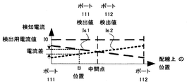
Rw1およびRw2はそれぞれポート111から下位ECU302接続部までの距離、および、ポート112から下位ECU302接続部までの距離に比例するため、検知電流であるIs1とIs2の値と下位ECU302の接続場所(配線上の位置)との関係をグラフで表すと図2のようになる。このグラフをみると分かるように、Is1とIs2との差(Is1-Is2)と配線上の位置との間には一意の関係がある。具体的には、簡単のためにRs1=Rs2=Rsであるとき、Is1-Is2は、式3のように表わされる。

これを利用して下位ECU302の接続場所(配線上の位置)を測定することができる。すなわち、上位コントローラ12(コントローラ)は、複数の下位ECU301~304(通信機器)のそれぞれに対して測定された電流Is1(第1電流値)と電流Is2(第2電流値)の差に基づいて、複数の下位ECU301~304のバス配線2(バス)上の順序を同定する。
また、この計算の際に、式4に示すように式3の値をさらにIs1とIs2の和(Is1+Is2=I0)で除した値を用いると式中からI0が消去され、I0のばらつきによる誤差を受けずに安定した測定が可能となる。すなわち、上位コントローラ12(コントローラ)は、複数の下位ECU301~304(通信機器)のそれぞれに対して測定された電流Is1(第1電流値)と電流Is2(第2電流値)の差と、電流Is1と電流Is2の和との比に基づいて、複数の下位ECU301~304のバス配線2(バス)上の順序を同定する。

なお、多くの用途では、必ずしも下位ECUの接続位置を正確に求める必要はない。これは、接続位置測定の目的は「バス配線とその課題」の段落にて述べたように各下位ECUがどのアクチュエータ等を担当しているのかを判定することであり、これを判定するには接続位置の順番(上位ECU1の各ポートからの距離の大小関係)が同定できればそれで十分であるからである。
また、式4の分母に着目すると、電流検出抵抗器141および142の抵抗値Rsが大きいと感度が低下してしまうことが分かる。これを極力避けるためには、Rw1やRw2に対してRsの値を十分に小さくすることが有効である。
換言すれば、電流センサCSは、電流検出抵抗器141、142(シャント抵抗)を用いて電流を測定し、電流検出抵抗器141、142の抵抗値は、ポート111(第1ポート)からポート112(第2ポート)までのバス配線2(バス)の抵抗値よりも小さい。
[適用例]
図6は、下位ECUの順序を同定する前のシステムを模式的に示した図である。バス配線2には、1つの上位ECU1と4つの下位ECU300が接続されている。下位ECU300のそれぞれには、センサ又はアクチュエータ(以下、S/Aと省略)が接続されている。上位ECU1は、下位ECU300のID(識別子)を用いて、下位ECU300と通信することができる。しかし、当初、それぞれのIDに対応する下位ECU300がどこに接続されているか不明であるとする。
図6は、下位ECUの順序を同定する前のシステムを模式的に示した図である。バス配線2には、1つの上位ECU1と4つの下位ECU300が接続されている。下位ECU300のそれぞれには、センサ又はアクチュエータ(以下、S/Aと省略)が接続されている。上位ECU1は、下位ECU300のID(識別子)を用いて、下位ECU300と通信することができる。しかし、当初、それぞれのIDに対応する下位ECU300がどこに接続されているか不明であるとする。
図7は、上位ECU1の不揮発性メモリ(例えば、上位コントローラ12に内蔵されるフラッシュメモリなど)に備えられるテーブル1Tを示す図である。テーブル1Tの第1レコードには、設計情報として、S/AのIDの順序が記憶されている。図7の例では、テーブル1Tの第1レコードは、バス配線2のポート111に近い順に、1番目の下位ECU300には#1のIDを持つS/Aが接続され、2番目の下位ECU300には#2のIDを持つS/Aが接続され、3番目の下位ECU300には#3のIDを持つS/Aが接続され、4番目の下位ECU300には#4のIDを持つS/Aが接続されていることを示している。
上位ECU1は、それぞれの下位ECU300に対して測定された電流値の差分(Is1-Is2)を大きい順に並べることにより、4つの下位ECU300のバス配線2上の順序を同定する。そして、上位ECU1は、下位ECU300のIDの順序をテーブル1Tの第2レコードとして記憶する。図7の例では、テーブル1Tの第2レコードは、バス配線2のポート111に近い順に、1番目の下位ECU300のIDは#Dであり、2番目の下位ECU300のIDは#Aであり、3番目の下位ECU300のIDは#Cであり、4番目の下位ECU300のIDは#Bであることを示している。
上位ECU1は、テーブル1Tの第1レコードと第2レコードを対比して、図8に示すように、#Dの下位ECU300に#1のS/Aが接続され、#Aの下位ECU300に#2のS/Aが接続され、#Cの下位ECU300に#3のS/Aが接続され、#Bの下位ECU300に#4のS/Aが接続されていることを同定する。
以上説明したように、本実施形態によれば、製造コストを抑制しつつ、バスに接続される通信機器の順序を同定することができる。
[実施形態のバリエーション]
本実施形態では各ポートでの電流を検出するために電流検出抵抗器141および142を用いているが、電流を検出することができれば、別の形態での電流検出手段を用いてもよい。例えば、ホールセンサ式の電流センサを用いても同様の効果を得ることができる。
本実施形態では各ポートでの電流を検出するために電流検出抵抗器141および142を用いているが、電流を検出することができれば、別の形態での電流検出手段を用いてもよい。例えば、ホールセンサ式の電流センサを用いても同様の効果を得ることができる。
また、本発明の実施形態の主目的は前述のように各下位ECUがどのアクチュエータ等を担当しているのかを判定することであるが、システム100の運用中も継続して接続位置測定を継続することで、その変化の有無から下位制御装置および配線の異常有無を診断することもできる。接続位置や配線構成を変更していないのに接続位置の測定結果が有意に変化したとしたら、下位制御装置または配線に何らかの異常が生じたと判断できるからである。
換言すれば、上位コントローラ12(コントローラ)は、複数の下位ECU301~304(通信機器)の1つである対象通信機器に対して測定された電流Is1(第1電流値)及び電流Is2(第2電流値)が時間の経過とともに変化した場合、前記対象通信機器又はバス配線2(バス)に故障が発生したと判定する。上位コントローラ12は、故障が発生したと判定した場合、例えば、警告灯を点灯することにより故障が発生したことを報知する。
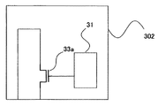
また、本実施形態では測定用電流I0を流すための手段として負荷抵抗32およびスイッチ33を直列に接続して構成したものを用いているが、図3に示すようにMOSFET33aのみを用いて、ON時にMOSFET33aが飽和状態となることで所望の測定用電流I0を流す構成となっていてもよい。
換言すれば、電流印加装置CAは、MOSFET33a、下位コントローラ31(コントローラ)を備える。MOSFET33aは、配線21と配線22の間に接続される。下位コントローラ31は、バス配線2(バス)に電流を印加する指令を受信した場合、MOSFET33aのゲート電圧を制御し、MOSFET33aを飽和状態とする。第1の実施形態と比較して、電流印加装置CAの素子数が減少するため、製造コストを低減することができる。
他にも、配線21と22との間のインピーダンスを変化させて電流を流す構成となっていればその実装手段はここに挙げたものに限定されるものではない。
また、本実施形態において、バス配線2は2本の配線から構成される例を示しているが、3本以上からなる構成となっていてもよい。
(第2の実施形態)
[第1の実施形態との差異]
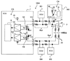
次に、本発明の第2の実施形態による電子制御装置としての上位ECU1を含むシステム100Aの構成と動作について、図4を用いて説明する。
[第1の実施形態との差異]
次に、本発明の第2の実施形態による電子制御装置としての上位ECU1を含むシステム100Aの構成と動作について、図4を用いて説明する。
本実施形態におけるシステム100Aの構成は、下位ECU301~304内に下位ECU内部電源34を備えているほかは、第1の実施形態と同一である。なお、負荷抵抗32(抵抗器)は、下位ECU内部電源34(内部電源)に接続される。
動作としても、第1の実施形態において配線21と22間のインピーダンスを変化させて測定用電流I0を流していたのに対し、本実施形態では下位ECU内部電源34と配線22との間のインピーダンスを変化させて測定用電流I0を流す点が異なる他は第1の実施形態と同一である。
本実施形態は、下位ECU301~304が動作する電源電圧と上位ECU1の電源15の電圧が異なる場合に有効である。
(第3の実施形態)
[第1の実施形態との差異]
次に、本発明の第3の実施形態による電子制御装置としての上位ECU1を含むシステム100Bの構成と動作について、図5を用いて説明する。
[第1の実施形態との差異]
次に、本発明の第3の実施形態による電子制御装置としての上位ECU1を含むシステム100Bの構成と動作について、図5を用いて説明する。
本実施形態におけるシステム100Bの構成は、第1の実施形態の構成に加えて、上位コントローラ12および下位コントローラ31にそれぞれパターン生成器17および35が接続されているほかは、第1の実施形態の構成と同一である。
本実施形態における電子制御装置等の動作について、主に第1の実施形態と異なるところを説明する。パターン生成器17および35は、両者とも同一の、自己相関の高い時系列パターンを生成する。
下位コントローラ31は、パターン生成器35から与えられたパターンに応じてスイッチ33のON/OFFを切り替える。その結果、測定用電流I0は当該パターンにて変調される。そして上位コントローラ12はI0が分流されたIs1およびIs2の検出値をパターン生成器17から与えられたパターンに応じて復調し、Is1およびIs2の復調値の大きさから対象とする下位ECU302の接続場所を測定する。
換言すれば、複数の下位ECU301~304(通信機器)は、自己相関の高い時系列パターンを生成するパターン生成器35をそれぞれ備える。下位コントローラ31(コントローラ)は、バス配線2(バス)に電流を印加する指令を受信した場合、パターン生成器35によって生成された時系列パターンに応じてスイッチ33をオン/オフする。電子制御装置としての上位ECU1は、自己相関の高い時系列パターンを生成するパターン生成器17を備える。上位コントローラ12(コントローラ)は、パターン生成器17によって生成された時系列パターンに応じて、電流Is1(第1電流値)と電流Is2(第2電流値)を復調する。
このように自己相関の高い時系列パターンにて変復調することによって、本実施形態は第1の実施形態と比べ、ノイズに対する耐性を高めることができる。ここで用いる自己相関の高い時系列パターンとしては、代表的なものとしてM系列(Maximum length sequence)を用いることができる。また、M系列から派生したGold系列も有用である。この他にも、自己相関の高い系列であれば同様の目的を達することができる。
なお、本発明は上記した実施形態に限定されるものではなく、様々な変形例が含まれる。例えば、上述した実施形態は本発明を分かりやすく説明するために詳細に説明したものであり、必ずしも説明した全ての構成を備えるものに限定されるものではない。また、ある実施形態の構成の一部を他の実施形態の構成に置き換えることが可能であり、また、ある実施形態の構成に他の実施形態の構成を加えることも可能である。また、各実施形態の構成の一部について、他の構成の追加・削除・置換をすることが可能である。
また、上記の各構成、機能等は、それらの一部又は全部を、例えば集積回路で設計する等によりハードウェアで実現してもよい。また、上記の各構成、機能等は、プロセッサ(コントローラ)がそれぞれの機能を実現するプログラムを解釈し、実行することによりソフトウェアで実現してもよい。各機能を実現するプログラム、テーブル、ファイル等の情報は、メモリや、ハードディスク、SSD(Solid State Drive)等の記録装置、または、ICカード、SDカード、DVD等の記録媒体に置くことができる。
なお、本発明の実施形態は、以下の態様であってもよい。
(1)複数の下位制御装置とバス状の配線で接続され、2つ以上の配線接続口と、各前記配線接続口における配線電流を検知する手段を有する電子制御装置であって、特定の前記下位制御装置にて印加された電流の各前記接続口における2つの検出値の関係から前記特定の下位制御装置の配線上の位置を測定することを特徴とする電子制御装置。
(2)(1)に記載の電子制御装置において、前記配線接続口の数は2つであり、両者の間をバス状配線でループ状に接続した構成としていることを特徴とする電子制御装置。
(3)(1)および(2)に記載の電子制御装置において、前記2つの検出値の関係とは、2つの検出値の差であることを特徴とする電子制御装置。
(4)(3)に記載の電子制御装置において、前記2つの検出値の関係とは、2つの検出値の差を、さらに2つの検出値の和で除した値であることを特徴とする電子制御装置。
(5)(1)および(2)に記載の電子制御装置において、前記特定の下位制御装置の配線上の位置を同定するにあたって、複数の下位制御装置における前記検出値の関係の大小関係に準じて位置を同定することを特徴とする電子制御装置。
(6)(1)および(2)に記載の電子制御装置において、各前記接続口での電流検知にシャント抵抗方式を用い、そのシャント抵抗の抵抗値がバス配線の全配線抵抗値よりも小さい値であることを特徴とする電子制御装置。
(7)(1)および(2)に記載の電子制御装置において、前記2つの検出値を継続的に計測し、その変化から下位制御装置および配線の異常有無を診断することを特徴とする電子制御装置。
(8)(1)および(2)に記載の電子制御装置において、前記下位制御装置にて電流を印加する手段は、前記バス状の配線の配線間のインピーダンスを変化させる構成としたものであることを特徴とする電子制御装置。
(9)(8)に記載の電子制御装置において、前記インピーダンスを変化させる手段は、抵抗器とスイッチを直列にして構成したものであることを特徴とする電子制御装置。
(10)(8)に記載の電子制御装置において、前記インピーダンスを変化させる手段は、MOSFETにより構成され、電流印加時に前記MOSFETを飽和状態とすることを特徴とする電子制御装置。
(11)(1)および(2)に記載の電子制御装置において、前記下位制御装置にて電流を印加する手段は、下位制御装置の内部電源から電流を印加する構成としたものであることを特徴とする電子制御装置。
(12)(1)および(2)に記載の電子制御装置において、下位制御装置にて印加する電流の時系列パターンに自己相関の高いパターンを用いることを特徴とする電子制御装置。
(13)(12)に記載の電子制御装置において、前記電流の時系列パターンはM系列またはその派生系列であることを特徴とする電子制御装置。
上記の(1)~(13)によれば、高速動作する回路を用いることなく下位ECUの接続位置を自動的かつ高い分解能で測定することができ、低コストで高信頼な電子制御装置、もしくはそれを備えたアクチュエータ、センサを提供することができる。
1…上位ECU
2…バス配線
12…上位コントローラ
15…電源
17…パターン生成器
21、22…配線
23…配線抵抗
31…下位コントローラ
32…負荷抵抗
33…スイッチ
33a…MOSFET
34…下位ECU内部電源
35…パターン生成器
100、100A、100B…システム
111、112…ポート
131、132…アンプ
141、142…電流検出抵抗器
301~304…下位ECU
CS…電流センサ
CA…電流印加装置
2…バス配線
12…上位コントローラ
15…電源
17…パターン生成器
21、22…配線
23…配線抵抗
31…下位コントローラ
32…負荷抵抗
33…スイッチ
33a…MOSFET
34…下位ECU内部電源
35…パターン生成器
100、100A、100B…システム
111、112…ポート
131、132…アンプ
141、142…電流検出抵抗器
301~304…下位ECU
CS…電流センサ
CA…電流印加装置
Claims (12)
- 複数の通信機器が接続されるバスの一端が接続される第1ポートと、
前記バスの他端が接続される第2ポートと、
前記複数の通信機器のそれぞれが前記バスに電流を印加することにより前記第1ポートに流れる電流の第1電流値及び前記第2ポートに流れる電流の第2電流値を測定する電流センサと、
前記複数の通信機器のそれぞれに対して測定された前記第1電流値と前記第2電流値に基づいて、前記複数の通信機器の前記バス上の順序を同定するコントローラと、
を備えることを特徴とする電子制御装置。 - 請求項1に記載の電子制御装置であって、
前記コントローラは、
前記複数の通信機器のそれぞれに対して測定された前記第1電流値と前記第2電流値の差に基づいて、前記複数の通信機器の前記バス上の順序を同定する ことを特徴とする電子制御装置。 - 請求項2に記載の電子制御装置であって、
前記コントローラは、
前記複数の通信機器のそれぞれに対して測定された前記第1電流値と前記第2電流値の差と、前記第1電流値と前記第2電流値の和との比に基づいて、前記複数の通信機器の前記バス上の順序を同定する
ことを特徴とする電子制御装置。 - 請求項1に記載の電子制御装置であって、
前記コントローラは、
前記バスに電流を印加する指令を前記複数の通信機器のそれぞれに送信する
ことを特徴とする電子制御装置。 - 請求項1に記載の電子制御装置であって、
自己相関の高い時系列パターンを生成するパターン生成器を備え、
前記コントローラは、
前記時系列パターンに応じて、前記第1電流値と前記第2電流値を復調する
ことを特徴とする電子制御装置。 - 請求項1に記載の電子制御装置であって、
前記電流センサは、
シャント抵抗を用いて電流を測定し、
前記シャント抵抗の抵抗値は、
前記第1ポートから前記第2ポートまでの前記バスの抵抗値よりも小さい
ことを特徴とする電子制御装置。 - 請求項1に記載の電子制御装置であって、
前記コントローラは、
前記複数の通信機器の1つである対象通信機器に対して測定された前記第1電流値及び第2電流値が時間の経過とともに変化した場合、前記対象通信機器又は前記バスに故障が発生したと判定する
ことを特徴とする電子制御装置。 - 第1配線と第2配線を含むバスに接続される通信機器であって、
バスに電流を印加する指令を受信した場合、前記第1配線と前記第2配線の間のインピーダンスを変更し、前記第1配線と前記第2配線の間に電流を流す電流印加装置を備える
ことを特徴とする通信機器。 - 請求項8に記載の通信機器であって、
前記電流印加装置は、
前記第1配線と前記第2配線の間に直列接続される抵抗器及びスイッチと、
前記指令を受信した場合、前記スイッチをオンするコントローラと、
を備えることを特徴とする通信機器。 - 請求項8に記載の通信機器であって、
前記電流印加装置は、
前記第1配線と前記第2配線の間に接続されるMOSFETと、
前記指令を受信した場合、前記MOSFETを飽和状態とするコントローラと、
を備えることを特徴とする通信機器。 - 請求項9に記載の通信機器であって、
内部電源を備え、
前記抵抗器は、
前記内部電源に接続される
ことを特徴とする通信機器。 - 請求項9に記載の通信機器であって、
自己相関の高い時系列パターンを生成するパターン生成器を備え、
前記コントローラは、
前記指令を受信した場合、前記時系列パターンに応じて前記スイッチをオン/オフする
ことを特徴とする通信機器。
Priority Applications (2)
| Application Number | Priority Date | Filing Date | Title |
|---|---|---|---|
| US16/338,279 US11128523B2 (en) | 2016-11-02 | 2017-10-24 | Electronic controller and communication apparatus |
| CN201780057339.7A CN110073339B (zh) | 2016-11-02 | 2017-10-24 | 电子控制装置及通信设备 |
Applications Claiming Priority (2)
| Application Number | Priority Date | Filing Date | Title |
|---|---|---|---|
| JP2016-214780 | 2016-11-02 | ||
| JP2016214780A JP6861013B2 (ja) | 2016-11-02 | 2016-11-02 | 電子制御装置及び通信機器 |
Publications (1)
| Publication Number | Publication Date |
|---|---|
| WO2018084018A1 true WO2018084018A1 (ja) | 2018-05-11 |
Family
ID=62075790
Family Applications (1)
| Application Number | Title | Priority Date | Filing Date |
|---|---|---|---|
| PCT/JP2017/038270 Ceased WO2018084018A1 (ja) | 2016-11-02 | 2017-10-24 | 電子制御装置及び通信機器 |
Country Status (4)
| Country | Link |
|---|---|
| US (1) | US11128523B2 (ja) |
| JP (1) | JP6861013B2 (ja) |
| CN (1) | CN110073339B (ja) |
| WO (1) | WO2018084018A1 (ja) |
Citations (3)
| Publication number | Priority date | Publication date | Assignee | Title |
|---|---|---|---|---|
| JPH11353566A (ja) * | 1998-06-11 | 1999-12-24 | Hitachi Electronics Service Co Ltd | センサ位置検出装置及び携帯端末 |
| JP2011135624A (ja) * | 2011-04-08 | 2011-07-07 | Mitsubishi Electric Corp | パワーコンバータのアドレス自動設定方法及びこの方法を適用した太陽光発電システム |
| WO2015131967A1 (de) * | 2014-03-06 | 2015-09-11 | Dr. Johannes Heidenhain Gmbh | Vorrichtung zur signalübertragung |
Family Cites Families (9)
| Publication number | Priority date | Publication date | Assignee | Title |
|---|---|---|---|---|
| US5444390A (en) * | 1994-02-02 | 1995-08-22 | Texas Digital Systems, Inc. | Means and method for sequentially testing electrical components |
| US6877054B2 (en) * | 2001-07-16 | 2005-04-05 | Rambus Inc. | Method and apparatus for position dependent data scheduling |
| JP2004317164A (ja) * | 2003-04-11 | 2004-11-11 | Kansai Electric Power Co Inc:The | 地絡故障検出装置および地絡故障遠隔監視システム |
| US20080253303A1 (en) | 2005-09-12 | 2008-10-16 | Koninklijke Philips Electronics, N.V. | Method to Determine a Relative Position of Devices in a Network and Network of Devices for Carrying Out the Method |
| DE502007004947D1 (de) * | 2007-10-22 | 2010-10-14 | Siemens Ag | Busanschalteinheit zum Zwischenschalten in eine Zweileiter-Stromschleife sowie Messumformer, Stellungsregler und analoge Ein- und Ausgabebaugruppe mit einer solchen Busanschalteinheit |
| DE102008034445B4 (de) * | 2008-07-24 | 2010-03-11 | Diehl Aerospace Gmbh | Verfahren und Einrichtung zum Erfassen von Bus-Teilnehmern |
| JP5498319B2 (ja) * | 2010-08-24 | 2014-05-21 | パナソニック株式会社 | 電流制御装置および通信システム |
| US10382312B2 (en) * | 2016-03-02 | 2019-08-13 | Fisher-Rosemount Systems, Inc. | Detecting and locating process control communication line faults from a handheld maintenance tool |
| US10599113B2 (en) * | 2016-03-03 | 2020-03-24 | Solaredge Technologies Ltd. | Apparatus and method for determining an order of power devices in power generation systems |
-
2016
- 2016-11-02 JP JP2016214780A patent/JP6861013B2/ja active Active
-
2017
- 2017-10-24 US US16/338,279 patent/US11128523B2/en active Active
- 2017-10-24 WO PCT/JP2017/038270 patent/WO2018084018A1/ja not_active Ceased
- 2017-10-24 CN CN201780057339.7A patent/CN110073339B/zh active Active
Patent Citations (3)
| Publication number | Priority date | Publication date | Assignee | Title |
|---|---|---|---|---|
| JPH11353566A (ja) * | 1998-06-11 | 1999-12-24 | Hitachi Electronics Service Co Ltd | センサ位置検出装置及び携帯端末 |
| JP2011135624A (ja) * | 2011-04-08 | 2011-07-07 | Mitsubishi Electric Corp | パワーコンバータのアドレス自動設定方法及びこの方法を適用した太陽光発電システム |
| WO2015131967A1 (de) * | 2014-03-06 | 2015-09-11 | Dr. Johannes Heidenhain Gmbh | Vorrichtung zur signalübertragung |
Also Published As
| Publication number | Publication date |
|---|---|
| CN110073339A (zh) | 2019-07-30 |
| US11128523B2 (en) | 2021-09-21 |
| JP6861013B2 (ja) | 2021-04-21 |
| JP2018074489A (ja) | 2018-05-10 |
| CN110073339B (zh) | 2023-05-05 |
| US20190319834A1 (en) | 2019-10-17 |
Similar Documents
| Publication | Publication Date | Title |
|---|---|---|
| CN109416382B (zh) | 接地损耗检测电路 | |
| US8957684B2 (en) | Method for detecting a fault of an operating switch for initiating a vehicle function of a vehicle and operating switch for carrying out the method | |
| DE102015102581A1 (de) | Hocheffiziente Diagnoseverfahren für monolithische Sensorsysteme | |
| EP2988136B1 (en) | Sensor interface circuits | |
| US11791752B2 (en) | Motor circuit | |
| CN105452636B (zh) | 可普遍使用的尤其用于运行λ探测器的控制与分析处理单元 | |
| CN106462128B (zh) | 能冗余的输入电路、具有至少一个输入电路的输入电路单元、和用于运行这种输入电路单元的方法 | |
| JP5409286B2 (ja) | 測定トランスデューサ | |
| US11131720B2 (en) | Electronic control device | |
| US9360344B2 (en) | Parallel reading of an analog sensor by two control units | |
| JP2014211382A (ja) | センサ装置 | |
| CN101688791B (zh) | 用于检测正交信号的装置 | |
| US8154312B2 (en) | Sensor system | |
| JP6313464B2 (ja) | 熱式空気流量センサ | |
| GB2507093A (en) | Method and circuit for measuring the electrical resistance of a thermocouple | |
| JP6861013B2 (ja) | 電子制御装置及び通信機器 | |
| CN105738750A (zh) | 用于识别用来操控多相致动器的控制设备的故障电流的方法和监控装置 | |
| CN111247395B (zh) | 电容式传感器系统 | |
| US11897445B2 (en) | Apparatus and method for determining a rotational speed of at least one wheel of a vehicle | |
| CN110780103A (zh) | 测量装置 | |
| CN107852353A (zh) | 用于网络装置的接口扩展装置和用于运行接口扩展装置的方法 | |
| US20060022527A1 (en) | Protective device in a controller | |
| JPH1165615A (ja) | 機能モジュールの位置検出方法 | |
| JPS61251777A (ja) | 状態変化検出装置 | |
| WO2017081759A1 (ja) | A/d変換装置 |
Legal Events
| Date | Code | Title | Description |
|---|---|---|---|
| 121 | Ep: the epo has been informed by wipo that ep was designated in this application |
Ref document number: 17868338 Country of ref document: EP Kind code of ref document: A1 |
|
| NENP | Non-entry into the national phase |
Ref country code: DE |
|
| 122 | Ep: pct application non-entry in european phase |
Ref document number: 17868338 Country of ref document: EP Kind code of ref document: A1 |