WO2018083973A1 - Capacitor - Google Patents
Capacitor Download PDFInfo
- Publication number
- WO2018083973A1 WO2018083973A1 PCT/JP2017/037518 JP2017037518W WO2018083973A1 WO 2018083973 A1 WO2018083973 A1 WO 2018083973A1 JP 2017037518 W JP2017037518 W JP 2017037518W WO 2018083973 A1 WO2018083973 A1 WO 2018083973A1
- Authority
- WO
- WIPO (PCT)
- Prior art keywords
- electrode
- lower electrode
- region
- capacitor
- upper electrode
- Prior art date
Links
- 239000003990 capacitor Substances 0.000 title claims description 49
- 239000000758 substrate Substances 0.000 claims abstract description 37
- 230000001681 protective effect Effects 0.000 description 18
- 238000010586 diagram Methods 0.000 description 16
- 229910052751 metal Inorganic materials 0.000 description 12
- 239000002184 metal Substances 0.000 description 12
- 238000004519 manufacturing process Methods 0.000 description 8
- 239000000463 material Substances 0.000 description 8
- 239000007769 metal material Substances 0.000 description 8
- 238000000034 method Methods 0.000 description 8
- 239000011810 insulating material Substances 0.000 description 7
- RYGMFSIKBFXOCR-UHFFFAOYSA-N Copper Chemical compound [Cu] RYGMFSIKBFXOCR-UHFFFAOYSA-N 0.000 description 6
- PXHVJJICTQNCMI-UHFFFAOYSA-N Nickel Chemical compound [Ni] PXHVJJICTQNCMI-UHFFFAOYSA-N 0.000 description 6
- VYPSYNLAJGMNEJ-UHFFFAOYSA-N Silicium dioxide Chemical compound O=[Si]=O VYPSYNLAJGMNEJ-UHFFFAOYSA-N 0.000 description 6
- 229910052782 aluminium Inorganic materials 0.000 description 6
- XAGFODPZIPBFFR-UHFFFAOYSA-N aluminium Chemical compound [Al] XAGFODPZIPBFFR-UHFFFAOYSA-N 0.000 description 6
- 229910052802 copper Inorganic materials 0.000 description 6
- 239000010949 copper Substances 0.000 description 6
- PCHJSUWPFVWCPO-UHFFFAOYSA-N gold Chemical compound [Au] PCHJSUWPFVWCPO-UHFFFAOYSA-N 0.000 description 6
- 229910052737 gold Inorganic materials 0.000 description 6
- 239000010931 gold Substances 0.000 description 6
- 229920002120 photoresistant polymer Polymers 0.000 description 6
- 229910052814 silicon oxide Inorganic materials 0.000 description 6
- 239000003989 dielectric material Substances 0.000 description 5
- BQCADISMDOOEFD-UHFFFAOYSA-N Silver Chemical compound [Ag] BQCADISMDOOEFD-UHFFFAOYSA-N 0.000 description 4
- 229910052709 silver Inorganic materials 0.000 description 4
- 239000004332 silver Substances 0.000 description 4
- 229910052581 Si3N4 Inorganic materials 0.000 description 3
- XUIMIQQOPSSXEZ-UHFFFAOYSA-N Silicon Chemical compound [Si] XUIMIQQOPSSXEZ-UHFFFAOYSA-N 0.000 description 3
- 229910052759 nickel Inorganic materials 0.000 description 3
- TWNQGVIAIRXVLR-UHFFFAOYSA-N oxo(oxoalumanyloxy)alumane Chemical compound O=[Al]O[Al]=O TWNQGVIAIRXVLR-UHFFFAOYSA-N 0.000 description 3
- 239000004065 semiconductor Substances 0.000 description 3
- 229910052710 silicon Inorganic materials 0.000 description 3
- 239000010703 silicon Substances 0.000 description 3
- HQVNEWCFYHHQES-UHFFFAOYSA-N silicon nitride Chemical compound N12[Si]34N5[Si]62N3[Si]51N64 HQVNEWCFYHHQES-UHFFFAOYSA-N 0.000 description 3
- VYZAMTAEIAYCRO-UHFFFAOYSA-N Chromium Chemical compound [Cr] VYZAMTAEIAYCRO-UHFFFAOYSA-N 0.000 description 2
- RTAQQCXQSZGOHL-UHFFFAOYSA-N Titanium Chemical compound [Ti] RTAQQCXQSZGOHL-UHFFFAOYSA-N 0.000 description 2
- PNEYBMLMFCGWSK-UHFFFAOYSA-N aluminium oxide Inorganic materials [O-2].[O-2].[O-2].[Al+3].[Al+3] PNEYBMLMFCGWSK-UHFFFAOYSA-N 0.000 description 2
- 230000015556 catabolic process Effects 0.000 description 2
- 229910052804 chromium Inorganic materials 0.000 description 2
- 239000011651 chromium Substances 0.000 description 2
- 239000004020 conductor Substances 0.000 description 2
- 229910000449 hafnium oxide Inorganic materials 0.000 description 2
- WIHZLLGSGQNAGK-UHFFFAOYSA-N hafnium(4+);oxygen(2-) Chemical compound [O-2].[O-2].[Hf+4] WIHZLLGSGQNAGK-UHFFFAOYSA-N 0.000 description 2
- 150000002739 metals Chemical class 0.000 description 2
- 150000004767 nitrides Chemical class 0.000 description 2
- BPUBBGLMJRNUCC-UHFFFAOYSA-N oxygen(2-);tantalum(5+) Chemical compound [O-2].[O-2].[O-2].[O-2].[O-2].[Ta+5].[Ta+5] BPUBBGLMJRNUCC-UHFFFAOYSA-N 0.000 description 2
- 229920001721 polyimide Polymers 0.000 description 2
- 239000009719 polyimide resin Substances 0.000 description 2
- 229910001936 tantalum oxide Inorganic materials 0.000 description 2
- 239000010936 titanium Substances 0.000 description 2
- 229910052719 titanium Inorganic materials 0.000 description 2
- JBRZTFJDHDCESZ-UHFFFAOYSA-N AsGa Chemical compound [As]#[Ga] JBRZTFJDHDCESZ-UHFFFAOYSA-N 0.000 description 1
- 229910001218 Gallium arsenide Inorganic materials 0.000 description 1
- ATJFFYVFTNAWJD-UHFFFAOYSA-N Tin Chemical compound [Sn] ATJFFYVFTNAWJD-UHFFFAOYSA-N 0.000 description 1
- 229910045601 alloy Inorganic materials 0.000 description 1
- 239000000956 alloy Substances 0.000 description 1
- 230000006866 deterioration Effects 0.000 description 1
- 239000006185 dispersion Substances 0.000 description 1
- 230000000694 effects Effects 0.000 description 1
- 238000005530 etching Methods 0.000 description 1
- 239000011521 glass Substances 0.000 description 1
- 239000011346 highly viscous material Substances 0.000 description 1
- 238000009413 insulation Methods 0.000 description 1
- 239000012212 insulator Substances 0.000 description 1
- 230000001590 oxidative effect Effects 0.000 description 1
- RVTZCBVAJQQJTK-UHFFFAOYSA-N oxygen(2-);zirconium(4+) Chemical compound [O-2].[O-2].[Zr+4] RVTZCBVAJQQJTK-UHFFFAOYSA-N 0.000 description 1
- 230000003071 parasitic effect Effects 0.000 description 1
- 238000007747 plating Methods 0.000 description 1
- 229910000679 solder Inorganic materials 0.000 description 1
- 238000004544 sputter deposition Methods 0.000 description 1
- 229910001928 zirconium oxide Inorganic materials 0.000 description 1
Images


Classifications
-
- H—ELECTRICITY
- H01—ELECTRIC ELEMENTS
- H01G—CAPACITORS; CAPACITORS, RECTIFIERS, DETECTORS, SWITCHING DEVICES OR LIGHT-SENSITIVE DEVICES, OF THE ELECTROLYTIC TYPE
- H01G4/00—Fixed capacitors; Processes of their manufacture
- H01G4/33—Thin- or thick-film capacitors
-
- H—ELECTRICITY
- H01—ELECTRIC ELEMENTS
- H01G—CAPACITORS; CAPACITORS, RECTIFIERS, DETECTORS, SWITCHING DEVICES OR LIGHT-SENSITIVE DEVICES, OF THE ELECTROLYTIC TYPE
- H01G4/00—Fixed capacitors; Processes of their manufacture
- H01G4/002—Details
- H01G4/005—Electrodes
- H01G4/012—Form of non-self-supporting electrodes
-
- H—ELECTRICITY
- H01—ELECTRIC ELEMENTS
- H01G—CAPACITORS; CAPACITORS, RECTIFIERS, DETECTORS, SWITCHING DEVICES OR LIGHT-SENSITIVE DEVICES, OF THE ELECTROLYTIC TYPE
- H01G4/00—Fixed capacitors; Processes of their manufacture
- H01G4/002—Details
- H01G4/018—Dielectrics
- H01G4/06—Solid dielectrics
- H01G4/08—Inorganic dielectrics
- H01G4/12—Ceramic dielectrics
-
- H—ELECTRICITY
- H01—ELECTRIC ELEMENTS
- H01G—CAPACITORS; CAPACITORS, RECTIFIERS, DETECTORS, SWITCHING DEVICES OR LIGHT-SENSITIVE DEVICES, OF THE ELECTROLYTIC TYPE
- H01G4/00—Fixed capacitors; Processes of their manufacture
- H01G4/002—Details
- H01G4/224—Housing; Encapsulation
-
- H—ELECTRICITY
- H01—ELECTRIC ELEMENTS
- H01G—CAPACITORS; CAPACITORS, RECTIFIERS, DETECTORS, SWITCHING DEVICES OR LIGHT-SENSITIVE DEVICES, OF THE ELECTROLYTIC TYPE
- H01G4/00—Fixed capacitors; Processes of their manufacture
- H01G4/002—Details
- H01G4/228—Terminals
-
- H—ELECTRICITY
- H01—ELECTRIC ELEMENTS
- H01L—SEMICONDUCTOR DEVICES NOT COVERED BY CLASS H10
- H01L21/00—Processes or apparatus adapted for the manufacture or treatment of semiconductor or solid state devices or of parts thereof
- H01L21/70—Manufacture or treatment of devices consisting of a plurality of solid state components formed in or on a common substrate or of parts thereof; Manufacture of integrated circuit devices or of parts thereof
- H01L21/77—Manufacture or treatment of devices consisting of a plurality of solid state components or integrated circuits formed in, or on, a common substrate
- H01L21/78—Manufacture or treatment of devices consisting of a plurality of solid state components or integrated circuits formed in, or on, a common substrate with subsequent division of the substrate into plural individual devices
- H01L21/82—Manufacture or treatment of devices consisting of a plurality of solid state components or integrated circuits formed in, or on, a common substrate with subsequent division of the substrate into plural individual devices to produce devices, e.g. integrated circuits, each consisting of a plurality of components
- H01L21/822—Manufacture or treatment of devices consisting of a plurality of solid state components or integrated circuits formed in, or on, a common substrate with subsequent division of the substrate into plural individual devices to produce devices, e.g. integrated circuits, each consisting of a plurality of components the substrate being a semiconductor, using silicon technology
-
- H—ELECTRICITY
- H01—ELECTRIC ELEMENTS
- H01L—SEMICONDUCTOR DEVICES NOT COVERED BY CLASS H10
- H01L27/00—Devices consisting of a plurality of semiconductor or other solid-state components formed in or on a common substrate
- H01L27/02—Devices consisting of a plurality of semiconductor or other solid-state components formed in or on a common substrate including semiconductor components specially adapted for rectifying, oscillating, amplifying or switching and having at least one potential-jump barrier or surface barrier; including integrated passive circuit elements with at least one potential-jump barrier or surface barrier
- H01L27/04—Devices consisting of a plurality of semiconductor or other solid-state components formed in or on a common substrate including semiconductor components specially adapted for rectifying, oscillating, amplifying or switching and having at least one potential-jump barrier or surface barrier; including integrated passive circuit elements with at least one potential-jump barrier or surface barrier the substrate being a semiconductor body
Definitions
- the present invention relates to a capacitor.
- MIM Metal Insulator Metal
- the MIM capacitor is a capacitor having a parallel plate type structure in which a dielectric is sandwiched between a lower electrode and an upper electrode.
- Patent Document 1 discloses such a capacitor.
- the capacitor described in Patent Document 1 includes a base electrode, a dielectric layer formed on the base electrode, an upper electrode layer formed on the dielectric layer, and a terminal electrode connected to the upper electrode layer. Have.
- the present invention has been made in view of such circumstances, and an object thereof is to reduce stress caused by the lower electrode and / or the upper electrode.
- a substrate having a first main surface and a second main surface, a lower electrode provided on the first main surface, and a dielectric film provided on the lower electrode And an upper electrode provided on the dielectric film, wherein at least one of the lower electrode and the upper electrode has a first region having a rectangular shape in plan view of the first main surface, and the first electrode And at least one second region protruding from at least one side of the region.
- the present invention it is possible to reduce the stress caused by the lower electrode and / or the upper electrode.
- FIG. 1 is a plan view schematically showing a structure of a capacitor 100 according to an embodiment of the present invention. It is a figure which shows the AA 'cross section of FIG. It is a figure which shows schematically the shape of the lower electrode 20 and the upper electrode 40 in planar view.
- 6 is a schematic diagram illustrating an example of a method for manufacturing the capacitor 100.
- FIG. 6 is a schematic diagram illustrating an example of a method for manufacturing the capacitor 100.
- FIG. 6 is a schematic diagram illustrating an example of a method for manufacturing the capacitor 100.
- FIG. 6 is a schematic diagram illustrating an example of a method for manufacturing the capacitor 100.
- FIG. 6 is a schematic diagram illustrating an example of a method for manufacturing the capacitor 100.
- FIG. 6 is a schematic diagram illustrating an example of a method for manufacturing the capacitor 100.
- FIG. 6 is a schematic diagram illustrating an example of a method for manufacturing the capacitor 100.
- FIG. 6 is a schematic diagram illustrating an example of a method for manufacturing the capacitor 100.
- FIG. FIG. 6 is a diagram showing another embodiment of a capacitor 100.
- FIG. 6 is a diagram showing another embodiment of a capacitor 100.
- FIG. 6 is a diagram showing another embodiment of a capacitor 100.
- FIG. 6 is a diagram showing another embodiment of a capacitor 100.
- FIG. 6 is a diagram showing another embodiment of a capacitor 100.
- FIG. 6 is a diagram showing another embodiment of a capacitor 100.
- FIG. 6 is a diagram showing another embodiment of a capacitor 100.
- FIG. 6 is a diagram showing another embodiment of a capacitor 100.
- FIG. 1 is a plan view schematically showing the structure of a capacitor 100 according to an embodiment of the present invention.
- FIG. 2 is a view showing a cross section taken along the line AA ′ of FIG. 1 and 2, the configuration necessary for explaining at least a part of the characteristics of the structure of the capacitor 100 is extracted and described, but the capacitor 100 is prevented from having a configuration (not shown). It is not a thing.
- the capacitor 100 includes a substrate 10, an insulating film 12, a lower electrode 20, a dielectric film 30, and an upper electrode 40.
- the capacitor 100 includes a via electrode 42 that is electrically connected to the lower electrode 20, a terminal electrode 70 that is electrically connected to the via electrode 42, and a terminal electrode 60 that is electrically connected to the upper electrode 40. Is provided.
- the substrate 10 is a surface (an example of a first main surface) that is a surface on which the lower electrode 20 is provided, and a back surface (an example of a second main surface) opposite to the surface of the substrate 10. ).
- the substrate 10 is rectangular in a plan view of the surface of the substrate 10 (that is, a plan view when the substrate 10 is viewed in the direction from the lower electrode 20 toward the substrate 10 (FIG. 1). Has a shape.
- the substrate 10 is a semiconductor substrate such as silicon.
- the long side length of the substrate 10 is, for example, 200 ⁇ m or more and 600 ⁇ m or less, and the short side length is 100 ⁇ m or more and 300 ⁇ m or less.
- the insulating film 12 is formed of, for example, silicon oxide.
- the insulating film 12 is formed of a material that is in close contact with the substrate 10 formed under the insulating film 12 and the lower electrode 20 formed over the insulating film 12.
- the insulating film 12 may be a film composed of a plurality of layers formed from different materials.
- the insulating film 12 only needs to be able to electrically insulate the substrate 10 and the lower electrode 20 and has a film thickness of, for example, about 0.5 ⁇ m to 3 ⁇ m.
- the substrate 10 may be formed of an insulating material such as alumina. In this case, the insulating film 12 may not be formed on the substrate 10.
- the lower electrode 20 is formed in a region inside the periphery of the substrate 10 in a plan view in the upper layer of the substrate 10.
- the shape of the lower electrode 20 in plan view will be described later.
- the film thickness of the lower electrode 20 may be 0.3 ⁇ m or more and 10 ⁇ m or less, and may be 0.5 ⁇ m or more and 5 ⁇ m or less.
- the series resistance can be lowered because the lower electrode 20 has a relatively thick film thickness.
- the lower electrode 20 is a metal made of, for example, copper, silver, gold, aluminum, nickel, chromium, titanium, or a conductor containing these metals. Further, the lower electrode 20 may be formed to have a plurality of layers formed of different materials.
- the dielectric film 30 is formed so as to cover the surface of the lower electrode 20. Specifically, the dielectric film 30 is formed so as to cover the upper surface (that is, the surface facing the upper electrode 40) and the end surface of the lower electrode 20, and at the position where the via electrode 42 is formed, the lower electrode 20 is formed. Has an exposed opening.
- the dielectric film 30 is formed of a dielectric or insulating material such as silicon oxide, silicon nitride, aluminum oxide, hafnium oxide, tantalum oxide, zirconium oxide, or other oxides or nitrides.
- the film thickness of the dielectric film 30 is, for example, not less than 0.02 ⁇ m and not more than 2 ⁇ m.
- the upper electrode 40 is located inside the lower electrode 20 on the dielectric film 30 in plan view. That is, the upper electrode 40 is positioned on the dielectric film 30 so that all of the upper electrode 40 overlaps at least a part of the lower electrode 20 in a plan view of the surface of the substrate 10.
- the shape of the lower electrode 20 in plan view will be described later.
- the film thickness of the upper electrode 40 may be, for example, 0.3 ⁇ m or more and 10 ⁇ m or less, or 0.5 ⁇ m or more and 5 ⁇ m or less. Thus, the series resistance can be lowered by the upper electrode 40 having a relatively thick film thickness.
- the via electrode 42 is an electrode that is electrically connected to the lower electrode 20.
- the via electrode 42 is located in a region other than a partial region where the upper electrode 40 is formed on the upper surface of the lower electrode 20 in plan view.
- the via electrode 42 is formed so as to fill the opening formed in the dielectric film 30. That is, the via electrode 42 is formed in contact with the lower electrode 20 inside the opening.
- the via electrode 42 may be formed from the inside of the opening to the dielectric film 30 around the opening.
- the upper electrode 40 and the via electrode 42 are formed of the same material.
- the upper electrode 40 and the via electrode 42 are, for example, a metal made of copper, silver, gold, aluminum, nickel, chromium, titanium, or a conductor containing these metals.
- the protective film 50 is formed so as to cover the upper electrode 40 and the via electrode 42. Further, the protective film 50 has an opening through which the upper electrode 40 and the via electrode 42 are exposed at the positions where the terminal electrodes 60 and 70 are formed. Further, the protective film 50 is formed so as to cover the dielectric film 30 and the insulating film 12 in a region outside the lower electrode 20 in a plan view, and is formed in a region inside the periphery of the substrate 10.
- the protective film 50 is formed of, for example, an insulating material such as polyimide resin or silicon oxide. Moreover, the film thickness of the protective film 50 is 1 micrometer or more and 20 micrometers or less, for example.
- the terminal electrode 60 is a terminal that is formed on the upper electrode 40 and the protective film 50 and electrically connects the upper electrode 40 and the outside.
- the terminal electrode 60 is formed so as to be directly connected to the upper electrode 40, but another conductive film may be formed between the terminal electrode 60 and the upper electrode.
- the terminal electrode 70 is a terminal that is formed on the protective film 50 and the via electrode 42 and electrically connects the lower electrode 20 and the outside.
- the terminal electrode 60 and the terminal electrode 70 may be a material having a lower resistivity than the material of the lower electrode 20 and the upper electrode 40, and are, for example, a metal made of copper, aluminum, or the like. As a result, the resistance can be lowered.
- the terminal electrode 70 may further have a metal film such as gold or tin on the surface thereof.
- the film thickness of the terminal electrode 60 and the terminal electrode 70 is, for example, 1 ⁇ m or more and 10 ⁇ m or less.
- FIG. 3 is a diagram schematically showing the shapes of the lower electrode 20 and the upper electrode 40 in plan view.
- the lower electrode 20 has a rectangular shape.
- the upper electrode 40 includes a first region 40-1 having a rectangular shape and two second regions 40-2 continuous from the first region 40-1.
- the first region 40-1 has two long sides and two short sides, and the two second regions 40-2 are regions 40 in a part of each of the two long sides.
- -1 is provided continuously from the region 40-1.
- the two second regions 40-2 are provided so as to face each other with the first region 40-1 interposed therebetween. That is, in the present embodiment, the upper electrode 40 has a cross shape.
- the two second regions 40-2 may be provided at positions shifted from each other in the long side direction of the first region 40-1.
- the upper electrode 40 since the upper electrode 40 has at least one second region 40-2 protruding from the first region 40-1, the stress generated in the upper electrode 40 can be relieved.
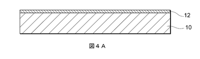
- FIGS. 4A to 4F are schematic views showing an example of a method for manufacturing the capacitor 100 according to the present embodiment.
- a method for manufacturing the capacitor 100 will be described with reference to FIGS. 4A to 4F.
- 4A to 4F one capacitor 100 is described.
- a plurality of capacitors 100 can be formed on the same substrate 10 at the same time.
- a substrate 10 is prepared, and an insulating film 12 is formed on the substrate 10.
- the substrate 10 is a silicon substrate
- the insulating film 12 is a silicon oxide film obtained by oxidizing the surface of the silicon substrate.
- the thickness of the substrate 10 is, for example, 100 ⁇ m or more and 300 ⁇ m or less.
- the capacitor 100 can be kept in a shape that is easy to handle during mounting while maintaining the mechanical strength of the substrate 10.
- the substrate 10 may be another semiconductor substrate such as gallium arsenide, or an insulating substrate such as glass or alumina.
- the film thickness of the insulating film 12 is about 0.1 ⁇ m or more and 3 ⁇ m or less, for example.
- the insulating film 12 only needs to have a thickness that can maintain insulation between the substrate 10 and the lower electrode 20.
- the insulating film 12 may be formed of an insulating material such as silicon nitride or aluminum oxide.
- a metal film made of a metal material constituting the lower electrode 20 is formed on the insulating film 12, the metal film is patterned with a photoresist, and the metal is used with the photoresist as a mask.
- the lower electrode 20 is formed by etching the film.
- the metal material include copper, silver, gold, and aluminum.
- the film thickness of the lower electrode 20 is, for example, not less than 0.5 ⁇ m and not more than 10 ⁇ m, and may be not less than 2 ⁇ m and not more than 6 ⁇ m.
- the resistance value of the lower electrode 20 can be set to a value that does not affect the high frequency characteristics of the capacitor 100, and is generated by the lower electrode 20 The stress to be applied can be suppressed to such an extent that the capacitor 100 is not distorted.
- a dielectric film 30 is formed.
- a dielectric material for forming the dielectric film 30 is deposited on the upper surface and end surfaces of the lower electrode 20 and the insulating film 12.
- the dielectric material is, for example, a silicon nitride film, and the film thickness is, for example, not less than 0.1 ⁇ m and not more than 1.5 ⁇ m.
- a part of the dielectric material is removed so that a part of the upper surface of the lower electrode 20 is exposed, an opening 32 is formed, and the dielectric film 30 is formed.
- the dielectric film 30 may be formed of a dielectric material made of another oxide or nitride such as silicon oxide, aluminum oxide, hafnium oxide, or tantalum oxide.
- the upper electrode 40 and the via electrode 42 are formed.
- a metal material for forming the upper electrode 40 and the via electrode 42 is deposited in the dielectric film 30, the insulating film 12, and the opening 32 (see FIG. 4C) of the dielectric film 30.
- the thicknesses of the upper electrode 40 and the via electrode 42 are, for example, 0.5 ⁇ m or more and 10 ⁇ m or less, and may be 2 ⁇ m or more and 6 ⁇ m or less.
- the series resistance can be lowered by the upper electrode 40 having a relatively thick film thickness.
- a metal material is copper, silver, gold
- the deposited metal material is etched to form the upper electrode 40 in a partial region of the lower electrode 20 and to form the via electrode 42 in the opening 32 of the dielectric film 30. To do.
- the lower electrode 20 is formed thicker than the upper electrode 40. Thereby, even if the upper electrode 40 is formed inside the lower electrode 20 in plan view, the equivalent series resistance can be kept low.
- a protective film 50 is formed.
- an insulating material for forming the protective film 50 is deposited on the upper electrode 40, the via electrode 42, the dielectric film 30, and the insulating film 12.
- the protective film 50 is formed of an insulating material such as polyimide resin or silicon oxide.
- the film thickness of the protective film 50 is, for example, 1 ⁇ m or more and 20 ⁇ m or less.
- the thickness of the protective film 50 can be controlled relatively easily. As a result, the dispersion
- the insulating material is etched to form openings 52 and 54 so that a part of the upper electrode 40 and a part of the via electrode 42 are exposed, respectively.
- the protective film 50 is formed so as to cover the side wall portion (side surface) of the lower electrode 20.
- a metal material is deposited on the openings 52 and 54 (see FIG. 4E) and the protective film 50, and this is etched using the patterned photoresist as a mask, thereby forming the terminal electrode 60. And 70 are formed.
- the metal material is, for example, copper or aluminum, and may be an alloy such as nickel and gold.
- the metal material is deposited by sputtering or plating.
- the capacitor 100 according to this embodiment can be obtained through the above steps.
- FIGS. 5 to 12 are diagrams showing other embodiments of the capacitor 100, respectively. Specifically, FIGS. 5 to 12 show examples of the shapes of the lower electrode 20 and the upper electrode 40 in plan view, respectively. In the following embodiments, description of matters common to the embodiments described in FIGS. 1 to 4 is omitted, and only different points will be described. In particular, the same operation effect by the same configuration will not be sequentially described for each embodiment.
- the lower electrode 20 has a rectangular shape.
- the upper electrode 40 includes a first region 40-1 having a rectangular shape and one or more second regions 40-2 projecting from the first region 40-1.
- the second region 40-2 may be provided so as to protrude from any side of the first region 40-1, and the position thereof may be any position (for example, the central portion) of the side. , End, etc.).
- one side of the first region 40-1 is such that the first region 40-1 and the second region 40-2 form a recess on one side of the first region 40-1.
- the lower electrode 20 includes a first region 20-1 having a rectangular shape and at least one second region 20-2 continuous from the first region 20-1.
- the upper electrode 40 has a rectangular shape.
- the second region 20-2 of the lower electrode 20 may be provided so as to protrude from any side of the first region 20-1, and the position thereof may be any position ( For example, it may be a central portion, an end portion, or the like. Further, the number of the second regions 20-2 protruding from one side of the first region 20-1 may be plural.
- the upper electrode 40 is located inside the first region 20-1 of the lower electrode 20. 10 and 11, the upper electrode 40 is positioned inside the second region 20-2 of the lower electrode 20 (that is, the upper electrode 40 is divided into a plurality of parts). In particular, since the upper electrode 40 is positioned inside the second region 20-2 of the lower electrode 20, the parasitic capacitance generated between the terminal electrodes 60 and 70 and the lower electrode 20 can be reduced.
- both the lower electrode 20 and the upper electrode 40 have first regions 20-1 and 40-1, and at least one second protrusion protruding from at least one of these regions. It has regions 20-2 and 40-2.
- the upper electrode 40 may be provided from the first region 20-1 to the second region 20-2 of the lower electrode 20, and the first region 20-1 of the lower electrode 20 may be provided. It may be provided so that it may be located inside.
- a capacitor 100 includes a substrate 10 having a front surface and a back surface, a lower electrode 20 provided on the front surface, a dielectric film 30 provided on the lower electrode 20, and a dielectric film 30.
- An upper electrode 40 provided, and at least one of the lower electrode 20 and the upper electrode 40 has a first region 20-1 and / or 40-1 having a rectangular shape in a plan view of the surface of the substrate 10, And at least one second region 20-2 and / or 40-2 protruding from at least one side of the first region 20-1 and / or 40-1.
- the second region 20-2 and / or 40-2 may have a rectangular shape, and may have a shape that can reduce stress generated by the lower electrode 20 and / or the upper electrode 40, such as a triangular shape or a fan shape. I just need it.
- the upper electrode 40 may be positioned inside the lower electrode 20 in a plan view.
- the lower electrode 20 may include a first region 20-1 and a second region 20-2, and the upper electrode 40 may be positioned inside the second region 20-2 in plan view. Thereby, the capacity
- each embodiment described above is for facilitating understanding of the present invention, and is not intended to limit the present invention.
- the present invention can be changed / improved without departing from the spirit thereof, and the present invention includes equivalents thereof.
- those obtained by appropriately modifying the design of each embodiment by those skilled in the art are also included in the scope of the present invention as long as they include the features of the present invention.
- each element included in each embodiment and its arrangement, material, condition, shape, size, and the like are not limited to those illustrated, and can be changed as appropriate.
- Each embodiment is an exemplification, and it is needless to say that a partial replacement or combination of configurations shown in different embodiments is possible, and these are also included in the scope of the present invention as long as they include the features of the present invention. .
Abstract
This invention is equipped with a substrate having a first main surface and a second main surface, a lower electrode provided on the first main surface, a dielectric film provided on the lower electrode, and an upper electrode provided on the dielectric film. The lower electrode and/or the upper electrode has, when viewed in plan view of the first main surface, a rectangular first region and at least one second region projecting from at least one side of the first region.
Description
本発明は、キャパシタに関する。
The present invention relates to a capacitor.
半導体集積回路に用いられる代表的なキャパシタ素子として、例えばMIM(Metal Insulator Metal)キャパシタがよく知られている。MIMキャパシタは、誘電体を下部電極と上部電極とで挟んだ平行平板型の構造を有するキャパシタである。
As a typical capacitor element used in a semiconductor integrated circuit, for example, a MIM (Metal Insulator Metal) capacitor is well known. The MIM capacitor is a capacitor having a parallel plate type structure in which a dielectric is sandwiched between a lower electrode and an upper electrode.
例えば特許文献1には、このようなキャパシタが開示されている。特許文献1に記載のキャパシタは、下地電極と、該下地電極上に形成された誘電体層と、該誘電体層上に形成された上部電極層と、上部電極層に接続された端子電極と、を有する。
For example, Patent Document 1 discloses such a capacitor. The capacitor described in Patent Document 1 includes a base electrode, a dielectric layer formed on the base electrode, an upper electrode layer formed on the dielectric layer, and a terminal electrode connected to the upper electrode layer. Have.
上記特許文献1に記載された従来のキャパシタでは、上部電極及び下部電極が矩形形状を有しているため、上部電極及び下部電極の低抵抗化のために膜厚を厚くすると、この膜厚に比例して応力が増加するため、素子破壊が発生する頻度が高くなり、キャパシタの信頼性が劣化するという問題が生じていた。
In the conventional capacitor described in Patent Document 1, since the upper electrode and the lower electrode have a rectangular shape, when the film thickness is increased in order to reduce the resistance of the upper electrode and the lower electrode, this film thickness is reduced. Since the stress increases proportionally, the frequency of element breakdown increases, resulting in a problem that the reliability of the capacitor deteriorates.
本発明はこのような事情に鑑みてなされたものであり、下部電極及び/又は上部電極を起因とする応力を低減させることを目的とする。
The present invention has been made in view of such circumstances, and an object thereof is to reduce stress caused by the lower electrode and / or the upper electrode.
本発明の一側面に係るキャパシタによれば、第1主面及び第2主面を有する基板と、前記第1主面上に設けられた下部電極と、前記下部電極上に設けられた誘電膜と、前記誘電膜上に設けられた上部電極とを備え、前記下部電極及び前記上部電極の少なくとも一方は、前記第1主面の平面視において、矩形形状を有する第1領域と、前記第1領域の少なくとも1つの辺から突出した、少なくとも1つの第2領域とを有する。
According to the capacitor of one aspect of the present invention, a substrate having a first main surface and a second main surface, a lower electrode provided on the first main surface, and a dielectric film provided on the lower electrode And an upper electrode provided on the dielectric film, wherein at least one of the lower electrode and the upper electrode has a first region having a rectangular shape in plan view of the first main surface, and the first electrode And at least one second region protruding from at least one side of the region.
本発明によれば、下部電極及び/又は上部電極を起因とする応力を低減させることが可能となる。
According to the present invention, it is possible to reduce the stress caused by the lower electrode and / or the upper electrode.
図1は、本発明の一実施形態に係るキャパシタ100の構造を概略的に示す平面図である。また、図2は、図1のAA´断面を示す図である。なお、図1及び図2においては、キャパシタ100の構造における特徴の少なくとも一部を説明するのに必要な構成を抽出して記載しているが、キャパシタ100が不図示の構成を備えることを妨げるものではない。
FIG. 1 is a plan view schematically showing the structure of a capacitor 100 according to an embodiment of the present invention. FIG. 2 is a view showing a cross section taken along the line AA ′ of FIG. 1 and 2, the configuration necessary for explaining at least a part of the characteristics of the structure of the capacitor 100 is extracted and described, but the capacitor 100 is prevented from having a configuration (not shown). It is not a thing.
キャパシタ100は、基板10と、絶縁膜12と、下部電極20と、誘電膜30と、上部電極40とを備えて構成される。また、キャパシタ100は、下部電極20に電気的に接続されたビア電極42と、ビア電極42に電気的に接続された端子電極70と、上部電極40に電気的に接続された端子電極60とを備える。
The capacitor 100 includes a substrate 10, an insulating film 12, a lower electrode 20, a dielectric film 30, and an upper electrode 40. The capacitor 100 includes a via electrode 42 that is electrically connected to the lower electrode 20, a terminal electrode 70 that is electrically connected to the via electrode 42, and a terminal electrode 60 that is electrically connected to the upper electrode 40. Is provided.
基板10は、下部電極20が設けられた側の面である表面(第1主面の一例である。)と、基板10における当該表面と反対側の裏面(第2主面の一例である。)とを有する。基板10は、基板10の表面の平面視(すなわち、下部電極20から基板10に向かう方向に基板10を見た平面視(図1)。以下、単に「平面視」ともいう。)において、矩形形状を有する。基板10は、例えばシリコンなどの半導体基板である。基板10の長辺の長さは、例えば、200μm以上600μm以下、短辺の長さは100μm以上300μm以下である。
The substrate 10 is a surface (an example of a first main surface) that is a surface on which the lower electrode 20 is provided, and a back surface (an example of a second main surface) opposite to the surface of the substrate 10. ). The substrate 10 is rectangular in a plan view of the surface of the substrate 10 (that is, a plan view when the substrate 10 is viewed in the direction from the lower electrode 20 toward the substrate 10 (FIG. 1). Has a shape. The substrate 10 is a semiconductor substrate such as silicon. The long side length of the substrate 10 is, for example, 200 μm or more and 600 μm or less, and the short side length is 100 μm or more and 300 μm or less.
絶縁膜12は、例えば酸化シリコンなどにより形成される。また、絶縁膜12は、絶縁膜12の下に形成される基板10及び絶縁膜12の上に形成される下部電極20と密着する材料により形成される。絶縁膜12は、異なる材料から形成された複数の層からなる膜であってもよい。絶縁膜12は基板10と下部電極20を電気的に絶縁できればよく、その膜厚は、例えば、0.5μm以上3μm以下程度である。また、基板10は、例えばアルミナなどの絶縁材料により形成されてもよい。この場合、絶縁膜12は、基板10上に形成されなくともよい。
The insulating film 12 is formed of, for example, silicon oxide. The insulating film 12 is formed of a material that is in close contact with the substrate 10 formed under the insulating film 12 and the lower electrode 20 formed over the insulating film 12. The insulating film 12 may be a film composed of a plurality of layers formed from different materials. The insulating film 12 only needs to be able to electrically insulate the substrate 10 and the lower electrode 20 and has a film thickness of, for example, about 0.5 μm to 3 μm. The substrate 10 may be formed of an insulating material such as alumina. In this case, the insulating film 12 may not be formed on the substrate 10.
下部電極20は、基板10の上層において、平面視で基板10の周縁の内側の領域に形成される。下部電極20の平面視における形状については後述する。下部電極20の膜厚は、下部電極20の膜厚は、0.3μm以上10μm以下でよく、また、0.5μm以上5μm以下であってもよい。このように、下部電極20が比較的厚い膜厚を有することにより、直列抵抗を下げることができる。
The lower electrode 20 is formed in a region inside the periphery of the substrate 10 in a plan view in the upper layer of the substrate 10. The shape of the lower electrode 20 in plan view will be described later. The film thickness of the lower electrode 20 may be 0.3 μm or more and 10 μm or less, and may be 0.5 μm or more and 5 μm or less. Thus, the series resistance can be lowered because the lower electrode 20 has a relatively thick film thickness.
下部電極20は、例えば、銅、銀、金、アルミニウム、ニッケル、クロム、チタン等からなる金属又はこれらの金属を含む導電体である。また、下部電極20は、異なる材料から形成された複数の層を有するように形成されてもよい。
The lower electrode 20 is a metal made of, for example, copper, silver, gold, aluminum, nickel, chromium, titanium, or a conductor containing these metals. Further, the lower electrode 20 may be formed to have a plurality of layers formed of different materials.
誘電膜30は、下部電極20の表面を覆うように形成される。具体的には、誘電膜30は、下部電極20の上面(すなわち、上部電極40と対向する面)及び端面を覆うように形成されるとともに、ビア電極42が形成される位置において、下部電極20が露出した開口を有する。誘電膜30は、例えば、酸化シリコン、窒化シリコン、酸化アルミニウム、酸化ハフニウム、酸化タンタル、酸化ジルコニウム等の酸化物、窒化物などの誘電性ないし絶縁性を有する材料により形成される。誘電膜30の膜厚は、例えば、0.02μm以上2μm以下である。
The dielectric film 30 is formed so as to cover the surface of the lower electrode 20. Specifically, the dielectric film 30 is formed so as to cover the upper surface (that is, the surface facing the upper electrode 40) and the end surface of the lower electrode 20, and at the position where the via electrode 42 is formed, the lower electrode 20 is formed. Has an exposed opening. The dielectric film 30 is formed of a dielectric or insulating material such as silicon oxide, silicon nitride, aluminum oxide, hafnium oxide, tantalum oxide, zirconium oxide, or other oxides or nitrides. The film thickness of the dielectric film 30 is, for example, not less than 0.02 μm and not more than 2 μm.
上部電極40は、誘電膜30上において、平面視で下部電極20の内側に位置する。すなわち、上部電極40は、基板10の表面の平面視において、その全てが下部電極20の少なくとも一部と重なるように、誘電膜30上に位置する。下部電極20の平面視における形状については後述する。上部電極40の膜厚は、例えば、0.3μm以上10μm以下でよく、0.5μm以上5μm以下であってもよい。このように、上部電極40が比較的厚い膜厚を有することにより、直列抵抗を下げることができる。
The upper electrode 40 is located inside the lower electrode 20 on the dielectric film 30 in plan view. That is, the upper electrode 40 is positioned on the dielectric film 30 so that all of the upper electrode 40 overlaps at least a part of the lower electrode 20 in a plan view of the surface of the substrate 10. The shape of the lower electrode 20 in plan view will be described later. The film thickness of the upper electrode 40 may be, for example, 0.3 μm or more and 10 μm or less, or 0.5 μm or more and 5 μm or less. Thus, the series resistance can be lowered by the upper electrode 40 having a relatively thick film thickness.
ビア電極42は、下部電極20に対して電気的に接続された電極である。ビア電極42は、平面視において、下部電極20の上面における、上部電極40が形成される一部の領域以外の領域に位置する。また、ビア電極42は、誘電膜30に形成された開口を充填するように形成される。すなわち、ビア電極42は、当該開口の内部において、下部電極20と接触するように形成される。また、ビア電極42は、当該開口の内部から当該開口の周囲における誘電膜30上に亘って形成されてもよい。
The via electrode 42 is an electrode that is electrically connected to the lower electrode 20. The via electrode 42 is located in a region other than a partial region where the upper electrode 40 is formed on the upper surface of the lower electrode 20 in plan view. The via electrode 42 is formed so as to fill the opening formed in the dielectric film 30. That is, the via electrode 42 is formed in contact with the lower electrode 20 inside the opening. The via electrode 42 may be formed from the inside of the opening to the dielectric film 30 around the opening.
本実施形態において、上部電極40及びビア電極42は、同一の材料で形成される。上部電極40及びビア電極42は、例えば、銅、銀、金、アルミニウム、ニッケル、クロム、チタン等からなる金属又はこれらの金属を含む導電体である。
In the present embodiment, the upper electrode 40 and the via electrode 42 are formed of the same material. The upper electrode 40 and the via electrode 42 are, for example, a metal made of copper, silver, gold, aluminum, nickel, chromium, titanium, or a conductor containing these metals.
保護膜50は、上部電極40及びビア電極42を覆うように形成される。また、保護膜50は、端子電極60及び70が形成される位置において、それぞれ、上部電極40及びビア電極42が露出した開口を有する。また、保護膜50は、平面視において、下部電極20の外側の領域において、誘電膜30及び絶縁膜12を覆うように形成され、かつ、基板10の周縁の内側の領域に形成されている。保護膜50は、例えば、ポリイミド樹脂や酸化シリコンなどの絶縁材料により形成される。また、保護膜50の膜厚は、例えば、1μm以上20μm以下である。
The protective film 50 is formed so as to cover the upper electrode 40 and the via electrode 42. Further, the protective film 50 has an opening through which the upper electrode 40 and the via electrode 42 are exposed at the positions where the terminal electrodes 60 and 70 are formed. Further, the protective film 50 is formed so as to cover the dielectric film 30 and the insulating film 12 in a region outside the lower electrode 20 in a plan view, and is formed in a region inside the periphery of the substrate 10. The protective film 50 is formed of, for example, an insulating material such as polyimide resin or silicon oxide. Moreover, the film thickness of the protective film 50 is 1 micrometer or more and 20 micrometers or less, for example.
端子電極60は、上部電極40及び保護膜50上に形成され、上部電極40と外部とを電気的に接続する端子である。本実施形態において、端子電極60は、上部電極40と直接接続されるように形成されているが、端子電極60と上部電極との間に、他の導電膜が形成されてもよい。
The terminal electrode 60 is a terminal that is formed on the upper electrode 40 and the protective film 50 and electrically connects the upper electrode 40 and the outside. In the present embodiment, the terminal electrode 60 is formed so as to be directly connected to the upper electrode 40, but another conductive film may be formed between the terminal electrode 60 and the upper electrode.
端子電極70は、保護膜50及びビア電極42上に形成され、下部電極20と外部とを電気的に接続する端子である。端子電極60及び端子電極70は、下部電極20及び上部電極40の材料よりも抵抗率の低い材料であってよく、例えば、銅やアルミニウム等からなる金属である。これにより抵抗を下げることが可能となる。また、端子電極70は、その表面にさらに、金やスズなどの金属膜を有してもよい。端子電極60及び端子電極70の膜厚は、例えば、1μm以上10μm以下である。
The terminal electrode 70 is a terminal that is formed on the protective film 50 and the via electrode 42 and electrically connects the lower electrode 20 and the outside. The terminal electrode 60 and the terminal electrode 70 may be a material having a lower resistivity than the material of the lower electrode 20 and the upper electrode 40, and are, for example, a metal made of copper, aluminum, or the like. As a result, the resistance can be lowered. The terminal electrode 70 may further have a metal film such as gold or tin on the surface thereof. The film thickness of the terminal electrode 60 and the terminal electrode 70 is, for example, 1 μm or more and 10 μm or less.
図3は、平面視における、下部電極20及び上部電極40の形状を概略的に示す図である。本実施形態において、下部電極20は、矩形形状を有する。また、上部電極40は、矩形形状を有する第1領域40-1と、第1領域40-1から連続する2つの第2領域40-2とを有する。具体的には、第1領域40-1は、2つの長辺及び2つの短辺を有しており、2つの第2領域40-2は、2つの長辺のそれぞれの一部において領域40-1から突出するように、領域40-1から連続して設けられている。また、2つの第2領域40-2は、第1領域40-1を挟んで互いに対向するように設けられている。すなわち、本実施形態において、上部電極40は、十字型の形状を有する。なお、2つの第2領域40-2は、第1領域40-1の長辺方向において、互いにずれた位置に設けられてもよい。このように、上部電極40が、第1領域40-1から突出した、少なくとも1つの第2領域40-2を有するので、上部電極40に発生する応力を緩和させることができる。
FIG. 3 is a diagram schematically showing the shapes of the lower electrode 20 and the upper electrode 40 in plan view. In the present embodiment, the lower electrode 20 has a rectangular shape. The upper electrode 40 includes a first region 40-1 having a rectangular shape and two second regions 40-2 continuous from the first region 40-1. Specifically, the first region 40-1 has two long sides and two short sides, and the two second regions 40-2 are regions 40 in a part of each of the two long sides. -1 is provided continuously from the region 40-1. The two second regions 40-2 are provided so as to face each other with the first region 40-1 interposed therebetween. That is, in the present embodiment, the upper electrode 40 has a cross shape. Note that the two second regions 40-2 may be provided at positions shifted from each other in the long side direction of the first region 40-1. Thus, since the upper electrode 40 has at least one second region 40-2 protruding from the first region 40-1, the stress generated in the upper electrode 40 can be relieved.
図4A~Fは、本実施形態に係るキャパシタ100の製造方法の一例を示す模式図である。以下、図4A~Fを用いて、キャパシタ100の製造方法について説明する。なお、図4A~Fでは、1つのキャパシタ100について説明するが、同一の基板10に複数のキャパシタ100を同時に形成することができる。
4A to 4F are schematic views showing an example of a method for manufacturing the capacitor 100 according to the present embodiment. Hereinafter, a method for manufacturing the capacitor 100 will be described with reference to FIGS. 4A to 4F. 4A to 4F, one capacitor 100 is described. However, a plurality of capacitors 100 can be formed on the same substrate 10 at the same time.
図4Aに示すように、まず、基板10を用意し、基板10上に絶縁膜12を形成する。例えば、基板10はシリコン基板であり、絶縁膜12はシリコン基板の表面を酸化した酸化シリコン膜である。基板10の厚さは、例えば、100μm以上300μm以下である。基板10の厚さを100μm以上300μm以下とすると、基板10の機械的強度を保ちつつ、キャパシタ100を実装時にハンドリングし易い形状に保つことができる。なお、基板10は、ガリウムヒ素等の他の半導体基板や、ガラスやアルミナ等の絶縁性基板であってもよい。また、絶縁膜12の膜厚は、例えば、0.1μm以上3μm以下程度である。もっとも、絶縁膜12は、基板10と下部電極20との間の絶縁が保てる厚さであればよい。絶縁膜12は、窒化シリコン、酸化アルミニウム等の絶縁材料により形成されてもよい。
As shown in FIG. 4A, first, a substrate 10 is prepared, and an insulating film 12 is formed on the substrate 10. For example, the substrate 10 is a silicon substrate, and the insulating film 12 is a silicon oxide film obtained by oxidizing the surface of the silicon substrate. The thickness of the substrate 10 is, for example, 100 μm or more and 300 μm or less. When the thickness of the substrate 10 is 100 μm or more and 300 μm or less, the capacitor 100 can be kept in a shape that is easy to handle during mounting while maintaining the mechanical strength of the substrate 10. The substrate 10 may be another semiconductor substrate such as gallium arsenide, or an insulating substrate such as glass or alumina. Moreover, the film thickness of the insulating film 12 is about 0.1 μm or more and 3 μm or less, for example. However, the insulating film 12 only needs to have a thickness that can maintain insulation between the substrate 10 and the lower electrode 20. The insulating film 12 may be formed of an insulating material such as silicon nitride or aluminum oxide.
次に、図4Bに示すように、絶縁膜12上に、下部電極20を構成する金属材料からなる金属膜を形成し、当該金属膜をフォトレジストでパターニングし、当該フォトレジストをマスクとして当該金属膜をエッチングすることにより、下部電極20を形成する。金属材料は、例えば、銅、銀、金、アルミニウム等である。また、下部電極20の膜厚は、例えば、0.5μm以上10μm以下であり、また、2μm以上6μm以下であってもよい。下部電極20の膜厚を0.5μm以上10μm以下とすると、下部電極20の抵抗値を、キャパシタ100の高周波特性に影響を与えない程度の値にすることができ、また、下部電極20により発生する応力をキャパシタ100が歪まない程度に抑えることができる。
Next, as shown in FIG. 4B, a metal film made of a metal material constituting the lower electrode 20 is formed on the insulating film 12, the metal film is patterned with a photoresist, and the metal is used with the photoresist as a mask. The lower electrode 20 is formed by etching the film. Examples of the metal material include copper, silver, gold, and aluminum. Moreover, the film thickness of the lower electrode 20 is, for example, not less than 0.5 μm and not more than 10 μm, and may be not less than 2 μm and not more than 6 μm. When the thickness of the lower electrode 20 is 0.5 μm or more and 10 μm or less, the resistance value of the lower electrode 20 can be set to a value that does not affect the high frequency characteristics of the capacitor 100, and is generated by the lower electrode 20 The stress to be applied can be suppressed to such an extent that the capacitor 100 is not distorted.
次に、図4Cに示すように、誘電膜30を形成する。まず、誘電膜30を形成する誘電体材料を、下部電極20の上面及び端面、並びに、絶縁膜12上に堆積させる。誘電体材料は、例えば、シリコン窒化膜で、その膜厚は、例えば、0.1μm以上1.5μm以下である。そして、パターニングされたフォトレジストをマスクとして、下部電極20の上面の一部が露出するように、誘電体材料の一部を除去して、開口32を形成し、誘電膜30を形成する。誘電膜30は、酸化シリコン、酸化アルミニウム、酸化ハフニウム、酸化タンタル等の他の酸化物や窒化物からなる誘電体材料により形成されてもよい。
Next, as shown in FIG. 4C, a dielectric film 30 is formed. First, a dielectric material for forming the dielectric film 30 is deposited on the upper surface and end surfaces of the lower electrode 20 and the insulating film 12. The dielectric material is, for example, a silicon nitride film, and the film thickness is, for example, not less than 0.1 μm and not more than 1.5 μm. Then, using the patterned photoresist as a mask, a part of the dielectric material is removed so that a part of the upper surface of the lower electrode 20 is exposed, an opening 32 is formed, and the dielectric film 30 is formed. The dielectric film 30 may be formed of a dielectric material made of another oxide or nitride such as silicon oxide, aluminum oxide, hafnium oxide, or tantalum oxide.
次に、図4Dに示すように、上部電極40及びビア電極42を形成する。まず、上部電極40及びビア電極42を形成する金属材料を、誘電膜30、絶縁膜12、及び、誘電膜30の開口32(図4C参照)内に堆積させる。上部電極40及びビア電極42の厚さは、例えば、0.5μm以上10μm以下であり、また、2μm以上6μm以下であってもよい。このように、上部電極40が比較的厚い膜厚を有することにより、直列抵抗を下げることができる。また、金属材料は、例えば、銅、銀、金、アルミニウム等である。そして、パターニングされたフォトレジストをマスクとして、堆積された金属材料をエッチングして、下部電極20の一部の領域に上部電極40を形成するとともに、誘電膜30の開口32にビア電極42を形成する。
Next, as shown in FIG. 4D, the upper electrode 40 and the via electrode 42 are formed. First, a metal material for forming the upper electrode 40 and the via electrode 42 is deposited in the dielectric film 30, the insulating film 12, and the opening 32 (see FIG. 4C) of the dielectric film 30. The thicknesses of the upper electrode 40 and the via electrode 42 are, for example, 0.5 μm or more and 10 μm or less, and may be 2 μm or more and 6 μm or less. Thus, the series resistance can be lowered by the upper electrode 40 having a relatively thick film thickness. Moreover, a metal material is copper, silver, gold | metal | money, aluminum etc., for example. Then, using the patterned photoresist as a mask, the deposited metal material is etched to form the upper electrode 40 in a partial region of the lower electrode 20 and to form the via electrode 42 in the opening 32 of the dielectric film 30. To do.
なお、本実施形態において、下部電極20は、上部電極40よりも、膜厚が厚く形成される。これにより、平面視において上部電極40が下部電極20よりも内側に形成されたとしても、等価直列抵抗を低く抑えることができる。
In the present embodiment, the lower electrode 20 is formed thicker than the upper electrode 40. Thereby, even if the upper electrode 40 is formed inside the lower electrode 20 in plan view, the equivalent series resistance can be kept low.
次に、図4Eに示すように、保護膜50を形成する。まず、保護膜50を形成する絶縁材料を、上部電極40、ビア電極42、誘電膜30、及び絶縁膜12上に堆積させる。保護膜50は、ポリイミド樹脂や酸化シリコンなどの絶縁材料により形成される。保護膜50の膜厚は、例えば、1μm以上20μm以下である。これにより、保護膜50を挟んで下部電極20と端子電極60との間に形成される容量を、誘電膜30を挟んで下部電極20と上部電極40との間に形成される容量よりも大きくすることができる。また、保護膜50を形成する材料として、高粘度の材料を必ずしも用いる必要がないため、保護膜50の厚さを比較的容易に制御することができる。ひいては、キャパシタ100の容量のばらつきを低減させることができる。
Next, as shown in FIG. 4E, a protective film 50 is formed. First, an insulating material for forming the protective film 50 is deposited on the upper electrode 40, the via electrode 42, the dielectric film 30, and the insulating film 12. The protective film 50 is formed of an insulating material such as polyimide resin or silicon oxide. The film thickness of the protective film 50 is, for example, 1 μm or more and 20 μm or less. Thereby, the capacitance formed between the lower electrode 20 and the terminal electrode 60 with the protective film 50 interposed therebetween is larger than the capacitance formed between the lower electrode 20 and the upper electrode 40 with the dielectric film 30 interposed therebetween. can do. Moreover, since it is not always necessary to use a highly viscous material as a material for forming the protective film 50, the thickness of the protective film 50 can be controlled relatively easily. As a result, the dispersion | variation in the capacity | capacitance of the capacitor 100 can be reduced.
そして、パターニングされたフォトレジストをマスクとして、当該絶縁材料をエッチングして、それぞれ、上部電極40の一部及びビア電極42の一部が露出するように、開口52及び54を形成する。なお、本実施形態において、保護膜50は、下部電極20の側壁部分(側面)を覆うように形成される。これにより、仮に誘電膜30が下部電極20の側壁部分に十分に形成されなかったとしても、下部電極20が露出することを防ぐことができる。ひいては、キャパシタ100の実装時に、下部電極20の側壁部分においてはんだと下部電極20が短絡することを防ぐことができる。
Then, using the patterned photoresist as a mask, the insulating material is etched to form openings 52 and 54 so that a part of the upper electrode 40 and a part of the via electrode 42 are exposed, respectively. In the present embodiment, the protective film 50 is formed so as to cover the side wall portion (side surface) of the lower electrode 20. Thereby, even if the dielectric film 30 is not sufficiently formed on the side wall portion of the lower electrode 20, it is possible to prevent the lower electrode 20 from being exposed. As a result, it is possible to prevent the solder and the lower electrode 20 from being short-circuited at the side wall portion of the lower electrode 20 when the capacitor 100 is mounted.
次に、図4Fに示すように、開口52及び54(図4E参照)並びに保護膜50上に、金属材料を堆積させ、これをパターニングされたフォトレジストをマスクとしてエッチングすることにより、端子電極60及び70を形成する。金属材料は、例えば、銅やアルミニウムであり、また、ニッケルと金等の合金であってもよい。なお、金属材料は、スパッタリングやめっきにより堆積される。以上の工程により、本実施形態に係るキャパシタ100を得ることができる。
Next, as shown in FIG. 4F, a metal material is deposited on the openings 52 and 54 (see FIG. 4E) and the protective film 50, and this is etched using the patterned photoresist as a mask, thereby forming the terminal electrode 60. And 70 are formed. The metal material is, for example, copper or aluminum, and may be an alloy such as nickel and gold. The metal material is deposited by sputtering or plating. The capacitor 100 according to this embodiment can be obtained through the above steps.
図5~12は、ぞれぞれ、キャパシタ100の他の実施形態を示す図である。具体的には、図5~図12は、それぞれ、平面視における下部電極20及び上部電極40の形状の一例を示している。以下の実施形態では、図1~4で説明した実施形態と共通の事柄についての記述を省略し、異なる点についてのみ説明する。特に、同様の構成による同様の作用効果については実施形態毎には逐次言及しない。
5 to 12 are diagrams showing other embodiments of the capacitor 100, respectively. Specifically, FIGS. 5 to 12 show examples of the shapes of the lower electrode 20 and the upper electrode 40 in plan view, respectively. In the following embodiments, description of matters common to the embodiments described in FIGS. 1 to 4 is omitted, and only different points will be described. In particular, the same operation effect by the same configuration will not be sequentially described for each embodiment.
図5~7に示す例において、下部電極20は矩形形状を有する。また、これらの例において、上部電極40は、矩形形状を有する第1領域40-1と、第1領域40-1から突出する、1つ以上の第2領域40-2とを有する。各例に示すとおり、第2領域40-2は、第1領域40-1のいずれの辺から突出して設けられてもよく、また、その位置も、当該辺のいずれの位置(例えば、中央部、端部等)であってもよい。また、図7に示すように、第1領域40-1の1つの辺において、第1領域40-1及び第2領域40-2が凹部を形成する等、第1領域40-1の1つの辺から突出する第2領域40-2の数が複数であってよい。
5 to 7, the lower electrode 20 has a rectangular shape. In these examples, the upper electrode 40 includes a first region 40-1 having a rectangular shape and one or more second regions 40-2 projecting from the first region 40-1. As shown in each example, the second region 40-2 may be provided so as to protrude from any side of the first region 40-1, and the position thereof may be any position (for example, the central portion) of the side. , End, etc.). In addition, as shown in FIG. 7, one side of the first region 40-1 is such that the first region 40-1 and the second region 40-2 form a recess on one side of the first region 40-1. There may be a plurality of second regions 40-2 protruding from the side.
図8~11に示す例において、下部電極20は、矩形形状を有する第1領域20-1と、第1領域20-1から連続する、少なくとも1つの第2領域20-2とを有する。他方で、上部電極40は、矩形形状を有する。各例に示すとおり、下部電極20の第2領域20-2は、第1領域20-1のいずれの辺から突出して設けられてもよく、また、その位置も、当該辺のいずれの位置(例えば、中央部、端部等)であってもよい。また、第1領域20-1の1つの辺から突出する第2領域20-2の数も複数であってよい。
8 to 11, the lower electrode 20 includes a first region 20-1 having a rectangular shape and at least one second region 20-2 continuous from the first region 20-1. On the other hand, the upper electrode 40 has a rectangular shape. As shown in each example, the second region 20-2 of the lower electrode 20 may be provided so as to protrude from any side of the first region 20-1, and the position thereof may be any position ( For example, it may be a central portion, an end portion, or the like. Further, the number of the second regions 20-2 protruding from one side of the first region 20-1 may be plural.
図8及び9に示す例において、上部電極40は、下部電極20の第1領域20-1の内側に位置している。また、図10及び11に示す例において、上部電極40は、下部電極20の第2領域20-2の内側に位置する(すなわち、上部電極40が、複数個に分割されている。)。特に、上部電極40が、下部電極20の第2領域20-2の内側に位置することにより、端子電極60及び70と下部電極20との間で発生する寄生容量を低減させることができる。
8 and 9, the upper electrode 40 is located inside the first region 20-1 of the lower electrode 20. 10 and 11, the upper electrode 40 is positioned inside the second region 20-2 of the lower electrode 20 (that is, the upper electrode 40 is divided into a plurality of parts). In particular, since the upper electrode 40 is positioned inside the second region 20-2 of the lower electrode 20, the parasitic capacitance generated between the terminal electrodes 60 and 70 and the lower electrode 20 can be reduced.
図12に示す例においては、下部電極20及び上部電極40の双方が、第1領域20-1及び40-1を有し、また、これらの少なくとも1つの辺から突出した、少なくとも1つの第2領域20-2及び40-2を有する。上部電極40は、図12に示すように、下部電極20の第1領域20-1から第2領域20-2に亘って設けられてもよく、また、下部電極20の第1領域20-1の内側に位置するように設けられてもよい。
In the example shown in FIG. 12, both the lower electrode 20 and the upper electrode 40 have first regions 20-1 and 40-1, and at least one second protrusion protruding from at least one of these regions. It has regions 20-2 and 40-2. As shown in FIG. 12, the upper electrode 40 may be provided from the first region 20-1 to the second region 20-2 of the lower electrode 20, and the first region 20-1 of the lower electrode 20 may be provided. It may be provided so that it may be located inside.
以上、本発明の例示的な実施形態について説明した。
The exemplary embodiments of the present invention have been described above.
本発明の一実施形態に係るキャパシタ100は、表面及び裏面を有する基板10と、表面上に設けられた下部電極20と、下部電極20上に設けられた誘電膜30と、誘電膜30上に設けられた上部電極40と、を備え、下部電極20及び上部電極40の少なくとも一方は、基板10の表面の平面視において、矩形形状を有する第1領域20-1及び/又は40-1と、第1領域20-1及び/又は40-1の少なくとも1つの辺から突出した、少なくとも1つの第2領域20-2及び/又は40-2とを有する。これにより、下部電極20及び/又は上部電極40と保護膜50や誘電膜30との間に生じる、下部電極20及び/又は上部電極40を起因とする応力を低減させることができる。ひいては、下部電極20及び/又は上部電極40の膜厚を厚くしたとしても、応力を原因とする素子破壊を低減させることができ、キャパシタ100の信頼性の低下を抑えることができる。なお、第2領域20-2及び/又は40-2は、矩形形状であってよく、また、三角形状、扇形状など、下部電極20及び/又は上部電極40によって発生する応力を低減できる形状であればよい。
A capacitor 100 according to an embodiment of the present invention includes a substrate 10 having a front surface and a back surface, a lower electrode 20 provided on the front surface, a dielectric film 30 provided on the lower electrode 20, and a dielectric film 30. An upper electrode 40 provided, and at least one of the lower electrode 20 and the upper electrode 40 has a first region 20-1 and / or 40-1 having a rectangular shape in a plan view of the surface of the substrate 10, And at least one second region 20-2 and / or 40-2 protruding from at least one side of the first region 20-1 and / or 40-1. Thereby, the stress caused by the lower electrode 20 and / or the upper electrode 40 generated between the lower electrode 20 and / or the upper electrode 40 and the protective film 50 or the dielectric film 30 can be reduced. As a result, even if the film thickness of the lower electrode 20 and / or the upper electrode 40 is increased, the element breakdown caused by the stress can be reduced, and the deterioration of the reliability of the capacitor 100 can be suppressed. The second region 20-2 and / or 40-2 may have a rectangular shape, and may have a shape that can reduce stress generated by the lower electrode 20 and / or the upper electrode 40, such as a triangular shape or a fan shape. I just need it.
また、上部電極40は、平面視において、下部電極20の内側に位置してもよい。また、下部電極20は、第1領域20-1及び第2領域20-2を有し、上部電極40は、平面視において、第2領域20-2の内側に位置してもよい。これにより、下部電極20と端子電極60との間に発生する容量を低減させることができる。
Further, the upper electrode 40 may be positioned inside the lower electrode 20 in a plan view. Further, the lower electrode 20 may include a first region 20-1 and a second region 20-2, and the upper electrode 40 may be positioned inside the second region 20-2 in plan view. Thereby, the capacity | capacitance generate | occur | produced between the lower electrode 20 and the terminal electrode 60 can be reduced.
なお、以上説明した各実施形態は、本発明の理解を容易にするためのものであり、本発明を限定して解釈するためのものではない。本発明は、その趣旨を逸脱することなく、変更/改良され得るととともに、本発明にはその等価物も含まれる。即ち、各実施形態に当業者が適宜設計変更を加えたものも、本発明の特徴を備えている限り、本発明の範囲に包含される。例えば、各実施形態が備える各要素及びその配置、材料、条件、形状、サイズなどは、例示したものに限定されるわけではなく適宜変更することができる。また、各実施形態は例示であり、異なる実施形態で示した構成の部分的な置換又は組み合わせが可能であることは言うまでもなく、これらも本発明の特徴を含む限り本発明の範囲に包含される。
Each embodiment described above is for facilitating understanding of the present invention, and is not intended to limit the present invention. The present invention can be changed / improved without departing from the spirit thereof, and the present invention includes equivalents thereof. In other words, those obtained by appropriately modifying the design of each embodiment by those skilled in the art are also included in the scope of the present invention as long as they include the features of the present invention. For example, each element included in each embodiment and its arrangement, material, condition, shape, size, and the like are not limited to those illustrated, and can be changed as appropriate. Each embodiment is an exemplification, and it is needless to say that a partial replacement or combination of configurations shown in different embodiments is possible, and these are also included in the scope of the present invention as long as they include the features of the present invention. .
10…基板、12…絶縁膜、20…下部電極、20-1…第1領域、20-2…第2領域、30…誘電膜、40…上部電極、40-1…第1領域、40-2…第2領域、42…ビア電極、50…保護膜、60…端子電極、70…端子電極、100…キャパシタ。
DESCRIPTION OF SYMBOLS 10 ... Board | substrate, 12 ... Insulating film, 20 ... Lower electrode, 20-1 ... 1st area | region, 20-2 ... 2nd area | region, 30 ... Dielectric film, 40 ... Upper electrode, 40-1 ... 1st area | region, 40- 2 ... second region, 42 ... via electrode, 50 ... protective film, 60 ... terminal electrode, 70 ... terminal electrode, 100 ... capacitor.
Claims (4)
- 第1主面及び第2主面を有する基板と、
前記第1主面上に設けられた下部電極と、
前記下部電極上に設けられた誘電膜と、
前記誘電膜上に設けられた上部電極と
を備え、
前記下部電極及び前記上部電極の少なくとも一方は、前記第1主面の平面視において、矩形形状を有する第1領域と、前記第1領域の少なくとも1つの辺から突出した、少なくとも1つの第2領域とを有する、キャパシタ。 A substrate having a first main surface and a second main surface;
A lower electrode provided on the first main surface;
A dielectric film provided on the lower electrode;
An upper electrode provided on the dielectric film,
At least one of the lower electrode and the upper electrode includes a first region having a rectangular shape in plan view of the first main surface and at least one second region protruding from at least one side of the first region. And a capacitor. - 前記第2領域は、矩形形状を有する、請求項1に記載のキャパシタ。 The capacitor according to claim 1, wherein the second region has a rectangular shape.
- 前記上部電極は、前記第1主面の平面視において、前記下部電極の内側に位置する、請求項1又は2に記載のキャパシタ。 3. The capacitor according to claim 1, wherein the upper electrode is located inside the lower electrode in a plan view of the first main surface.
- 前記下部電極は、前記第1領域及び前記第2領域を有し、
前記上部電極は、前記第1主面の平面視において、前記第2領域の内側に位置する、請求項1又は2に記載のキャパシタ。 The lower electrode has the first region and the second region,
3. The capacitor according to claim 1, wherein the upper electrode is located inside the second region in a plan view of the first main surface.
Priority Applications (3)
| Application Number | Priority Date | Filing Date | Title |
|---|---|---|---|
| JP2018548611A JP6788847B2 (en) | 2016-11-02 | 2017-10-17 | Capacitor |
| CN201780066804.3A CN109923630B (en) | 2016-11-02 | 2017-10-17 | Capacitor with a capacitor body |
| US16/385,552 US11521800B2 (en) | 2016-11-02 | 2019-04-16 | Capacitor |
Applications Claiming Priority (2)
| Application Number | Priority Date | Filing Date | Title |
|---|---|---|---|
| JP2016215106 | 2016-11-02 | ||
| JP2016-215106 | 2016-11-02 |
Related Child Applications (1)
| Application Number | Title | Priority Date | Filing Date |
|---|---|---|---|
| US16/385,552 Continuation US11521800B2 (en) | 2016-11-02 | 2019-04-16 | Capacitor |
Publications (1)
| Publication Number | Publication Date |
|---|---|
| WO2018083973A1 true WO2018083973A1 (en) | 2018-05-11 |
Family
ID=62075844
Family Applications (1)
| Application Number | Title | Priority Date | Filing Date |
|---|---|---|---|
| PCT/JP2017/037518 WO2018083973A1 (en) | 2016-11-02 | 2017-10-17 | Capacitor |
Country Status (4)
| Country | Link |
|---|---|
| US (1) | US11521800B2 (en) |
| JP (1) | JP6788847B2 (en) |
| CN (1) | CN109923630B (en) |
| WO (1) | WO2018083973A1 (en) |
Cited By (1)
| Publication number | Priority date | Publication date | Assignee | Title |
|---|---|---|---|---|
| JPWO2021221087A1 (en) * | 2020-05-01 | 2021-11-04 |
Families Citing this family (2)
| Publication number | Priority date | Publication date | Assignee | Title |
|---|---|---|---|---|
| DE112018000336T5 (en) * | 2017-07-25 | 2019-09-19 | Murata Manufacturing Co., Ltd. | CAPACITOR |
| JP7427966B2 (en) * | 2020-01-16 | 2024-02-06 | Tdk株式会社 | electronic components |
Citations (2)
| Publication number | Priority date | Publication date | Assignee | Title |
|---|---|---|---|---|
| JPH0689831A (en) * | 1992-09-08 | 1994-03-29 | Toshiba Corp | Thin film capacitor |
| JPH09213908A (en) * | 1996-02-02 | 1997-08-15 | United Memories Inc | Semiconductor device and manufacturing method thereof |
Family Cites Families (13)
| Publication number | Priority date | Publication date | Assignee | Title |
|---|---|---|---|---|
| JPH06112429A (en) * | 1992-09-29 | 1994-04-22 | Toshiba Corp | Semiconductor memory and manufacture method thereof |
| JPH0757969A (en) * | 1993-08-20 | 1995-03-03 | Nippon Carbide Ind Co Inc | Capacitance stabilizing method for capacitor |
| US5699224A (en) * | 1995-10-25 | 1997-12-16 | Rohm Co., Ltd. | Thick-film capacitor and chip-type composite electronic component utilizing the same |
| JP4641396B2 (en) * | 2004-09-02 | 2011-03-02 | Okiセミコンダクタ株式会社 | Thin film capacitor and manufacturing method thereof |
| JP5061895B2 (en) * | 2005-02-04 | 2012-10-31 | 日本電気株式会社 | Capacitor and wiring board incorporating the capacitor |
| JP2007201158A (en) * | 2006-01-26 | 2007-08-09 | Kyocera Corp | Capacitor |
| JP2008277425A (en) * | 2007-04-26 | 2008-11-13 | Kyocera Corp | Capacitor |
| JP2009295683A (en) * | 2008-06-03 | 2009-12-17 | Tdk Corp | Chip-type electronic part |
| CN102113113A (en) * | 2008-08-04 | 2011-06-29 | 株式会社村田制作所 | Manufacturing method of dielectric thin-film capacitor and dielectric thin-film capacitor |
| JP5376186B2 (en) * | 2010-09-13 | 2013-12-25 | 株式会社村田製作所 | Dielectric thin film element, antifuse element, and method of manufacturing dielectric thin film element |
| JP6187196B2 (en) * | 2013-11-29 | 2017-08-30 | 株式会社村田製作所 | Capacitor element, resonator device, and method of manufacturing capacitor element |
| JP6357856B2 (en) * | 2014-05-12 | 2018-07-18 | Tdk株式会社 | Thin film capacitor |
| US20160293334A1 (en) | 2015-03-31 | 2016-10-06 | Tdk Corporation | Thin film capacitor |
-
2017
- 2017-10-17 JP JP2018548611A patent/JP6788847B2/en active Active
- 2017-10-17 CN CN201780066804.3A patent/CN109923630B/en active Active
- 2017-10-17 WO PCT/JP2017/037518 patent/WO2018083973A1/en active Application Filing
-
2019
- 2019-04-16 US US16/385,552 patent/US11521800B2/en active Active
Patent Citations (2)
| Publication number | Priority date | Publication date | Assignee | Title |
|---|---|---|---|---|
| JPH0689831A (en) * | 1992-09-08 | 1994-03-29 | Toshiba Corp | Thin film capacitor |
| JPH09213908A (en) * | 1996-02-02 | 1997-08-15 | United Memories Inc | Semiconductor device and manufacturing method thereof |
Cited By (3)
| Publication number | Priority date | Publication date | Assignee | Title |
|---|---|---|---|---|
| JPWO2021221087A1 (en) * | 2020-05-01 | 2021-11-04 | ||
| WO2021221087A1 (en) * | 2020-05-01 | 2021-11-04 | 株式会社村田製作所 | Semiconductor device and module |
| JP7420230B2 (en) | 2020-05-01 | 2024-01-23 | 株式会社村田製作所 | Semiconductor devices and modules |
Also Published As
| Publication number | Publication date |
|---|---|
| JPWO2018083973A1 (en) | 2019-09-19 |
| JP6788847B2 (en) | 2020-11-25 |
| CN109923630B (en) | 2023-04-28 |
| CN109923630A (en) | 2019-06-21 |
| US20190244761A1 (en) | 2019-08-08 |
| US11521800B2 (en) | 2022-12-06 |
Similar Documents
| Publication | Publication Date | Title |
|---|---|---|
| US11101072B2 (en) | Capacitor with limited substrate capacitance | |
| JP6372640B2 (en) | Capacitors | |
| JP6856095B2 (en) | Capacitor | |
| US20220384113A1 (en) | Capacitor | |
| WO2018083973A1 (en) | Capacitor | |
| JP2017195322A (en) | Chip capacitor | |
| US11158456B2 (en) | Trench capacitor | |
| JP2018133363A (en) | Electronic component built-in substrate and substrate mounting structure | |
| WO2018088265A1 (en) | Electronic component | |
| WO2022239717A1 (en) | Semiconductor device | |
| US11271074B2 (en) | Capacitor and method for manufacturing the same | |
| CN112041954B (en) | Capacitor assembly | |
| JP2017216432A (en) | Thin-film capacitor | |
| JP2012221990A (en) | Semiconductor device and manufacturing method of the same | |
| JP2017195320A (en) | Chip capacitor |
Legal Events
| Date | Code | Title | Description |
|---|---|---|---|
| 121 | Ep: the epo has been informed by wipo that ep was designated in this application |
Ref document number: 17867937 Country of ref document: EP Kind code of ref document: A1 |
|
| ENP | Entry into the national phase |
Ref document number: 2018548611 Country of ref document: JP Kind code of ref document: A |
|
| NENP | Non-entry into the national phase |
Ref country code: DE |
|
| 122 | Ep: pct application non-entry in european phase |
Ref document number: 17867937 Country of ref document: EP Kind code of ref document: A1 |