WO2018079040A1 - ダンパ装置 - Google Patents
ダンパ装置 Download PDFInfo
- Publication number
- WO2018079040A1 WO2018079040A1 PCT/JP2017/030384 JP2017030384W WO2018079040A1 WO 2018079040 A1 WO2018079040 A1 WO 2018079040A1 JP 2017030384 W JP2017030384 W JP 2017030384W WO 2018079040 A1 WO2018079040 A1 WO 2018079040A1
- Authority
- WO
- WIPO (PCT)
- Prior art keywords
- damper device
- torque
- input
- damper
- intermediate element
- Prior art date
- Legal status (The legal status is an assumption and is not a legal conclusion. Google has not performed a legal analysis and makes no representation as to the accuracy of the status listed.)
- Ceased
Links
Images




Classifications
-
- F—MECHANICAL ENGINEERING; LIGHTING; HEATING; WEAPONS; BLASTING
- F16—ENGINEERING ELEMENTS AND UNITS; GENERAL MEASURES FOR PRODUCING AND MAINTAINING EFFECTIVE FUNCTIONING OF MACHINES OR INSTALLATIONS; THERMAL INSULATION IN GENERAL
- F16F—SPRINGS; SHOCK-ABSORBERS; MEANS FOR DAMPING VIBRATION
- F16F15/00—Suppression of vibrations in systems; Means or arrangements for avoiding or reducing out-of-balance forces, e.g. due to motion
- F16F15/10—Suppression of vibrations in rotating systems by making use of members moving with the system
- F16F15/12—Suppression of vibrations in rotating systems by making use of members moving with the system using elastic members or friction-damping members, e.g. between a rotating shaft and a gyratory mass mounted thereon
- F16F15/121—Suppression of vibrations in rotating systems by making use of members moving with the system using elastic members or friction-damping members, e.g. between a rotating shaft and a gyratory mass mounted thereon using springs as elastic members, e.g. metallic springs
- F16F15/123—Wound springs
- F16F15/12353—Combinations of dampers, e.g. with multiple plates, multiple spring sets, i.e. complex configurations
-
- F—MECHANICAL ENGINEERING; LIGHTING; HEATING; WEAPONS; BLASTING
- F16—ENGINEERING ELEMENTS AND UNITS; GENERAL MEASURES FOR PRODUCING AND MAINTAINING EFFECTIVE FUNCTIONING OF MACHINES OR INSTALLATIONS; THERMAL INSULATION IN GENERAL
- F16D—COUPLINGS FOR TRANSMITTING ROTATION; CLUTCHES; BRAKES
- F16D3/00—Yielding couplings, i.e. with means permitting movement between the connected parts during the drive
- F16D3/02—Yielding couplings, i.e. with means permitting movement between the connected parts during the drive adapted to specific functions
- F16D3/12—Yielding couplings, i.e. with means permitting movement between the connected parts during the drive adapted to specific functions specially adapted for accumulation of energy to absorb shocks or vibration
-
- F—MECHANICAL ENGINEERING; LIGHTING; HEATING; WEAPONS; BLASTING
- F16—ENGINEERING ELEMENTS AND UNITS; GENERAL MEASURES FOR PRODUCING AND MAINTAINING EFFECTIVE FUNCTIONING OF MACHINES OR INSTALLATIONS; THERMAL INSULATION IN GENERAL
- F16D—COUPLINGS FOR TRANSMITTING ROTATION; CLUTCHES; BRAKES
- F16D7/00—Slip couplings, e.g. slipping on overload, for absorbing shock
- F16D7/02—Slip couplings, e.g. slipping on overload, for absorbing shock of the friction type
- F16D7/024—Slip couplings, e.g. slipping on overload, for absorbing shock of the friction type with axially applied torque limiting friction surfaces
- F16D7/025—Slip couplings, e.g. slipping on overload, for absorbing shock of the friction type with axially applied torque limiting friction surfaces with flat clutching surfaces, e.g. discs
-
- F—MECHANICAL ENGINEERING; LIGHTING; HEATING; WEAPONS; BLASTING
- F16—ENGINEERING ELEMENTS AND UNITS; GENERAL MEASURES FOR PRODUCING AND MAINTAINING EFFECTIVE FUNCTIONING OF MACHINES OR INSTALLATIONS; THERMAL INSULATION IN GENERAL
- F16F—SPRINGS; SHOCK-ABSORBERS; MEANS FOR DAMPING VIBRATION
- F16F15/00—Suppression of vibrations in systems; Means or arrangements for avoiding or reducing out-of-balance forces, e.g. due to motion
- F16F15/10—Suppression of vibrations in rotating systems by making use of members moving with the system
- F16F15/12—Suppression of vibrations in rotating systems by making use of members moving with the system using elastic members or friction-damping members, e.g. between a rotating shaft and a gyratory mass mounted thereon
- F16F15/1202—Suppression of vibrations in rotating systems by making use of members moving with the system using elastic members or friction-damping members, e.g. between a rotating shaft and a gyratory mass mounted thereon the damping action being at least partially controlled by centrifugal masses
-
- F—MECHANICAL ENGINEERING; LIGHTING; HEATING; WEAPONS; BLASTING
- F16—ENGINEERING ELEMENTS AND UNITS; GENERAL MEASURES FOR PRODUCING AND MAINTAINING EFFECTIVE FUNCTIONING OF MACHINES OR INSTALLATIONS; THERMAL INSULATION IN GENERAL
- F16F—SPRINGS; SHOCK-ABSORBERS; MEANS FOR DAMPING VIBRATION
- F16F15/00—Suppression of vibrations in systems; Means or arrangements for avoiding or reducing out-of-balance forces, e.g. due to motion
- F16F15/10—Suppression of vibrations in rotating systems by making use of members moving with the system
- F16F15/12—Suppression of vibrations in rotating systems by making use of members moving with the system using elastic members or friction-damping members, e.g. between a rotating shaft and a gyratory mass mounted thereon
- F16F15/1207—Suppression of vibrations in rotating systems by making use of members moving with the system using elastic members or friction-damping members, e.g. between a rotating shaft and a gyratory mass mounted thereon characterised by the supporting arrangement of the damper unit
-
- F—MECHANICAL ENGINEERING; LIGHTING; HEATING; WEAPONS; BLASTING
- F16—ENGINEERING ELEMENTS AND UNITS; GENERAL MEASURES FOR PRODUCING AND MAINTAINING EFFECTIVE FUNCTIONING OF MACHINES OR INSTALLATIONS; THERMAL INSULATION IN GENERAL
- F16F—SPRINGS; SHOCK-ABSORBERS; MEANS FOR DAMPING VIBRATION
- F16F15/00—Suppression of vibrations in systems; Means or arrangements for avoiding or reducing out-of-balance forces, e.g. due to motion
- F16F15/10—Suppression of vibrations in rotating systems by making use of members moving with the system
- F16F15/12—Suppression of vibrations in rotating systems by making use of members moving with the system using elastic members or friction-damping members, e.g. between a rotating shaft and a gyratory mass mounted thereon
- F16F15/121—Suppression of vibrations in rotating systems by making use of members moving with the system using elastic members or friction-damping members, e.g. between a rotating shaft and a gyratory mass mounted thereon using springs as elastic members, e.g. metallic springs
- F16F15/123—Wound springs
-
- F—MECHANICAL ENGINEERING; LIGHTING; HEATING; WEAPONS; BLASTING
- F16—ENGINEERING ELEMENTS AND UNITS; GENERAL MEASURES FOR PRODUCING AND MAINTAINING EFFECTIVE FUNCTIONING OF MACHINES OR INSTALLATIONS; THERMAL INSULATION IN GENERAL
- F16F—SPRINGS; SHOCK-ABSORBERS; MEANS FOR DAMPING VIBRATION
- F16F15/00—Suppression of vibrations in systems; Means or arrangements for avoiding or reducing out-of-balance forces, e.g. due to motion
- F16F15/10—Suppression of vibrations in rotating systems by making use of members moving with the system
- F16F15/12—Suppression of vibrations in rotating systems by making use of members moving with the system using elastic members or friction-damping members, e.g. between a rotating shaft and a gyratory mass mounted thereon
- F16F15/129—Suppression of vibrations in rotating systems by making use of members moving with the system using elastic members or friction-damping members, e.g. between a rotating shaft and a gyratory mass mounted thereon characterised by friction-damping means
-
- F—MECHANICAL ENGINEERING; LIGHTING; HEATING; WEAPONS; BLASTING
- F16—ENGINEERING ELEMENTS AND UNITS; GENERAL MEASURES FOR PRODUCING AND MAINTAINING EFFECTIVE FUNCTIONING OF MACHINES OR INSTALLATIONS; THERMAL INSULATION IN GENERAL
- F16F—SPRINGS; SHOCK-ABSORBERS; MEANS FOR DAMPING VIBRATION
- F16F15/00—Suppression of vibrations in systems; Means or arrangements for avoiding or reducing out-of-balance forces, e.g. due to motion
- F16F15/10—Suppression of vibrations in rotating systems by making use of members moving with the system
- F16F15/12—Suppression of vibrations in rotating systems by making use of members moving with the system using elastic members or friction-damping members, e.g. between a rotating shaft and a gyratory mass mounted thereon
- F16F15/131—Suppression of vibrations in rotating systems by making use of members moving with the system using elastic members or friction-damping members, e.g. between a rotating shaft and a gyratory mass mounted thereon the rotating system comprising two or more gyratory masses
- F16F15/133—Suppression of vibrations in rotating systems by making use of members moving with the system using elastic members or friction-damping members, e.g. between a rotating shaft and a gyratory mass mounted thereon the rotating system comprising two or more gyratory masses using springs as elastic members, e.g. metallic springs
- F16F15/134—Wound springs
-
- F—MECHANICAL ENGINEERING; LIGHTING; HEATING; WEAPONS; BLASTING
- F16—ENGINEERING ELEMENTS AND UNITS; GENERAL MEASURES FOR PRODUCING AND MAINTAINING EFFECTIVE FUNCTIONING OF MACHINES OR INSTALLATIONS; THERMAL INSULATION IN GENERAL
- F16F—SPRINGS; SHOCK-ABSORBERS; MEANS FOR DAMPING VIBRATION
- F16F15/00—Suppression of vibrations in systems; Means or arrangements for avoiding or reducing out-of-balance forces, e.g. due to motion
- F16F15/10—Suppression of vibrations in rotating systems by making use of members moving with the system
- F16F15/12—Suppression of vibrations in rotating systems by making use of members moving with the system using elastic members or friction-damping members, e.g. between a rotating shaft and a gyratory mass mounted thereon
- F16F15/131—Suppression of vibrations in rotating systems by making use of members moving with the system using elastic members or friction-damping members, e.g. between a rotating shaft and a gyratory mass mounted thereon the rotating system comprising two or more gyratory masses
- F16F15/139—Suppression of vibrations in rotating systems by making use of members moving with the system using elastic members or friction-damping members, e.g. between a rotating shaft and a gyratory mass mounted thereon the rotating system comprising two or more gyratory masses characterised by friction-damping means
-
- F—MECHANICAL ENGINEERING; LIGHTING; HEATING; WEAPONS; BLASTING
- F16—ENGINEERING ELEMENTS AND UNITS; GENERAL MEASURES FOR PRODUCING AND MAINTAINING EFFECTIVE FUNCTIONING OF MACHINES OR INSTALLATIONS; THERMAL INSULATION IN GENERAL
- F16F—SPRINGS; SHOCK-ABSORBERS; MEANS FOR DAMPING VIBRATION
- F16F15/00—Suppression of vibrations in systems; Means or arrangements for avoiding or reducing out-of-balance forces, e.g. due to motion
- F16F15/10—Suppression of vibrations in rotating systems by making use of members moving with the system
- F16F15/14—Suppression of vibrations in rotating systems by making use of members moving with the system using masses freely rotating with the system, i.e. uninvolved in transmitting driveline torque, e.g. rotative dynamic dampers
- F16F15/1407—Suppression of vibrations in rotating systems by making use of members moving with the system using masses freely rotating with the system, i.e. uninvolved in transmitting driveline torque, e.g. rotative dynamic dampers the rotation being limited with respect to the driving means
- F16F15/1464—Masses connected to driveline by a kinematic mechanism or gear system
- F16F15/1478—Masses connected to driveline by a kinematic mechanism or gear system with a planetary gear system
-
- F—MECHANICAL ENGINEERING; LIGHTING; HEATING; WEAPONS; BLASTING
- F16—ENGINEERING ELEMENTS AND UNITS; GENERAL MEASURES FOR PRODUCING AND MAINTAINING EFFECTIVE FUNCTIONING OF MACHINES OR INSTALLATIONS; THERMAL INSULATION IN GENERAL
- F16F—SPRINGS; SHOCK-ABSORBERS; MEANS FOR DAMPING VIBRATION
- F16F15/00—Suppression of vibrations in systems; Means or arrangements for avoiding or reducing out-of-balance forces, e.g. due to motion
- F16F15/30—Flywheels
-
- F—MECHANICAL ENGINEERING; LIGHTING; HEATING; WEAPONS; BLASTING
- F16—ENGINEERING ELEMENTS AND UNITS; GENERAL MEASURES FOR PRODUCING AND MAINTAINING EFFECTIVE FUNCTIONING OF MACHINES OR INSTALLATIONS; THERMAL INSULATION IN GENERAL
- F16F—SPRINGS; SHOCK-ABSORBERS; MEANS FOR DAMPING VIBRATION
- F16F2222/00—Special physical effects, e.g. nature of damping effects
- F16F2222/04—Friction
-
- F—MECHANICAL ENGINEERING; LIGHTING; HEATING; WEAPONS; BLASTING
- F16—ENGINEERING ELEMENTS AND UNITS; GENERAL MEASURES FOR PRODUCING AND MAINTAINING EFFECTIVE FUNCTIONING OF MACHINES OR INSTALLATIONS; THERMAL INSULATION IN GENERAL
- F16F—SPRINGS; SHOCK-ABSORBERS; MEANS FOR DAMPING VIBRATION
- F16F2222/00—Special physical effects, e.g. nature of damping effects
- F16F2222/08—Inertia
-
- F—MECHANICAL ENGINEERING; LIGHTING; HEATING; WEAPONS; BLASTING
- F16—ENGINEERING ELEMENTS AND UNITS; GENERAL MEASURES FOR PRODUCING AND MAINTAINING EFFECTIVE FUNCTIONING OF MACHINES OR INSTALLATIONS; THERMAL INSULATION IN GENERAL
- F16F—SPRINGS; SHOCK-ABSORBERS; MEANS FOR DAMPING VIBRATION
- F16F2232/00—Nature of movement
- F16F2232/02—Rotary
-
- F—MECHANICAL ENGINEERING; LIGHTING; HEATING; WEAPONS; BLASTING
- F16—ENGINEERING ELEMENTS AND UNITS; GENERAL MEASURES FOR PRODUCING AND MAINTAINING EFFECTIVE FUNCTIONING OF MACHINES OR INSTALLATIONS; THERMAL INSULATION IN GENERAL
- F16H—GEARING
- F16H45/00—Combinations of fluid gearings for conveying rotary motion with couplings or clutches
- F16H45/02—Combinations of fluid gearings for conveying rotary motion with couplings or clutches with mechanical clutches for bridging a fluid gearing of the hydrokinetic type
- F16H2045/0221—Combinations of fluid gearings for conveying rotary motion with couplings or clutches with mechanical clutches for bridging a fluid gearing of the hydrokinetic type with damping means
- F16H2045/0226—Combinations of fluid gearings for conveying rotary motion with couplings or clutches with mechanical clutches for bridging a fluid gearing of the hydrokinetic type with damping means comprising two or more vibration dampers
-
- F—MECHANICAL ENGINEERING; LIGHTING; HEATING; WEAPONS; BLASTING
- F16—ENGINEERING ELEMENTS AND UNITS; GENERAL MEASURES FOR PRODUCING AND MAINTAINING EFFECTIVE FUNCTIONING OF MACHINES OR INSTALLATIONS; THERMAL INSULATION IN GENERAL
- F16H—GEARING
- F16H45/00—Combinations of fluid gearings for conveying rotary motion with couplings or clutches
- F16H45/02—Combinations of fluid gearings for conveying rotary motion with couplings or clutches with mechanical clutches for bridging a fluid gearing of the hydrokinetic type
- F16H2045/0221—Combinations of fluid gearings for conveying rotary motion with couplings or clutches with mechanical clutches for bridging a fluid gearing of the hydrokinetic type with damping means
- F16H2045/0268—Combinations of fluid gearings for conveying rotary motion with couplings or clutches with mechanical clutches for bridging a fluid gearing of the hydrokinetic type with damping means the damper comprising a gearing
-
- F—MECHANICAL ENGINEERING; LIGHTING; HEATING; WEAPONS; BLASTING
- F16—ENGINEERING ELEMENTS AND UNITS; GENERAL MEASURES FOR PRODUCING AND MAINTAINING EFFECTIVE FUNCTIONING OF MACHINES OR INSTALLATIONS; THERMAL INSULATION IN GENERAL
- F16H—GEARING
- F16H45/00—Combinations of fluid gearings for conveying rotary motion with couplings or clutches
- F16H45/02—Combinations of fluid gearings for conveying rotary motion with couplings or clutches with mechanical clutches for bridging a fluid gearing of the hydrokinetic type
Definitions
- the invention of the present disclosure relates to an elastic body that transmits torque between an input element and an output element, and a damper device that includes a rotary inertia mass damper.
- a damper device of this type a first spring that transmits torque between a drive member (input element) and an intermediate member (intermediate element), and torque is transmitted between the intermediate member and a driven member (output element).
- Rotational inertia having a sun gear as a mass body provided in parallel with a torque transmission path including a second spring, an intermediate member, and first and second springs and rotating in accordance with relative rotation of the drive member and the driven member.
- the damping ratio ⁇ of the intermediate member determined based on the moment of inertia of the intermediate member and the rigidity of the first and second springs is less than 1.
- a plurality of natural frequencies (resonance frequencies) are set for the state in which the bending of the first and second elastic bodies is allowed, and the rotational speed of the input element
- the resonance of the intermediate element can be generated when the rotation speed corresponding to any one of the plurality of natural frequencies is reached.
- the vibration transmitted from the input element to the output element via the torque transmission path and the vibration transmitted from the input element to the output element via the rotary inertia mass damper theoretically cancel each other. It becomes possible to set two anti-resonance points. Therefore, the vibration damping performance of the damper device can be improved by matching the frequencies of the two anti-resonance points with the frequency of the vibration (resonance) to be damped by the damper device.
- the main object of the invention of the present disclosure is to further improve the vibration damping performance of the damper device.
- the damper device of the present disclosure includes an input element to which torque from an engine is transmitted, an intermediate element, an output element, a first elastic body that transmits torque between the input element and the intermediate element, and the intermediate element and the In a damper device including a second elastic body that transmits torque to and from an output element, the damper apparatus includes a mass body that rotates according to relative rotation between the input element and the output element, and the input element and the output element A rotary inertia mass damper provided in parallel with a torque transmission path including the first elastic body, the intermediate element, and the second elastic body, and a damping mechanism that attenuates resonance of the intermediate element. is there.
- a plurality of natural frequencies are set in a state where the bending of the first and second elastic bodies is allowed for the torque transmission path including the intermediate element, and the rotation of the input element
- the resonance of the intermediate element can be generated when the number reaches the number of rotations corresponding to any of the plurality of natural frequencies.
- the vibration damping performance of the damper device can be improved by bringing the frequencies of the two anti-resonance points closer to the frequency of the vibration (resonance) to be damped by the damper device.
- the damper device includes a damping mechanism that damps the resonance of the intermediate element. This suppresses an increase in the resonance amplitude of the intermediate member, and the inertial torque transmitted from the rotary inertia mass damper to the output element causes a vibration level near the resonance point of the intermediate member and the corresponding antiresonance point. Can be satisfactorily reduced. As a result, the vibration damping performance can be further improved in this damper device.
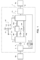
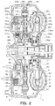
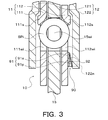
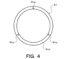
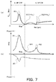
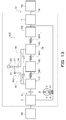
- FIG. 1 It is a schematic block diagram of the starting apparatus containing the damper apparatus of this indication. It is sectional drawing which shows the starting apparatus of FIG. It is an expanded sectional view showing the damping mechanism contained in the damper device of this indication. It is a front view which shows the friction member of a damping mechanism. It is a front view which shows the biasing member of a damping mechanism. It is a principal part expanded sectional view which shows the rotary inertia mass damper contained in the damper apparatus of this indication. (A) And (b) is explanatory drawing which illustrates the relationship between the rotation speed of an engine, and the torque fluctuation TFluc in the output element of the damper apparatus of FIG. It is an expanded sectional view showing other damper devices of this indication.
- FIG. 1 is a schematic configuration diagram illustrating a starting device 1 including a damper device 10 according to the present disclosure
- FIG. 2 is a cross-sectional view illustrating the starting device 1.
- a starting device 1 shown in these drawings is mounted on a vehicle including an engine (internal combustion engine) EG as a driving device, and is connected to a crankshaft of the engine EG in addition to the damper device 10.
- a front cover 3 as an input member to which torque from the EG is transmitted, a pump impeller (input side fluid transmission element) 4 fixed to the front cover 3, and a turbine runner (output side fluid) that can rotate coaxially with the pump impeller 4.
- a transmission element 5, a damper hub 7 as an output member connected to the damper device 10 and fixed to the input shaft IS of the transmission TM which is an automatic transmission (AT) or a continuously variable transmission (CVT), a lock-up clutch 8 etc. are included.
- axial direction basically indicates the extending direction of the central axis (axial center) of the starting device 1 or the damper device 10, unless otherwise specified.
- the “radial direction” is basically the radial direction of the rotating element such as the starting device 1, the damper device 10, and the damper device 10, unless otherwise specified, that is, the center of the starting device 1 or the damper device 10.
- An extending direction of a straight line extending from the axis in a direction (radial direction) orthogonal to the central axis is shown.
- the “circumferential direction” basically corresponds to the circumferential direction of the rotating elements of the starting device 1, the damper device 10, the damper device 10, etc., ie, the rotational direction of the rotating element, unless otherwise specified. Indicates direction.
- the pump impeller 4 is fixed to the front cover 3 tightly so as to define a fluid chamber 9 through which hydraulic oil flows, and a plurality of pump impellers 4 disposed on the inner surface of the pump shell 40. And a pump blade 41.
- the turbine runner 5 includes a turbine shell 50 and a plurality of turbine blades 51 disposed on the inner surface of the turbine shell 50.
- An inner peripheral portion of the turbine shell 50 is fixed to the damper hub 7 via a plurality of rivets.
- the pump impeller 4 and the turbine runner 5 face each other, and a stator 6 that rectifies the flow of hydraulic oil (working fluid) from the turbine runner 5 to the pump impeller 4 is coaxially disposed between the pump impeller 4 and the turbine runner 5.
- the stator 6 has a plurality of stator blades 60, and the rotation direction of the stator 6 is set in only one direction by the one-way clutch 61.
- the pump impeller 4, the turbine runner 5, and the stator 6 form a torus (annular flow path) for circulating hydraulic oil, and function as a torque converter (fluid transmission device) having a torque amplification function.
- the stator 6 and the one-way clutch 61 may be omitted, and the pump impeller 4 and the turbine runner 5 may function as a fluid coupling.
- the lockup clutch 8 is configured as a hydraulic multi-plate clutch, and performs lockup for connecting the front cover 3 and the damper hub 7 via the damper device 10 and releases the lockup.
- the lockup clutch 8 includes a lockup piston 80 that is supported by a center piece 30 fixed to the front cover 3 so as to be movable in the axial direction, a clutch drum 81, and the lockup piston 80.
- An annular clutch hub 82 fixed to the inner surface of the side wall 33 and a plurality of first friction engagement plates (friction plates having friction materials on both sides) fitted to splines formed on the inner periphery of the clutch drum 81.
- the front cover is arranged so that the lock-up clutch 8 is located on the opposite side of the front cover 3 with respect to the lock-up piston 80, that is, on the damper device 10 and the turbine runner 5 side with respect to the lock-up piston 80.
- 3 includes an annular flange member (oil chamber defining member) 85 attached to the center piece 30, and a plurality of return springs 86 disposed between the front cover 3 and the lockup piston 80.
- the lock-up piston 80 and the flange member 85 define an engagement oil chamber 87, and hydraulic oil (engagement oil pressure) is supplied to the engagement oil chamber 87 from a hydraulic control device (not shown). Is done.
- the lockup clutch 8 can be engaged (completely engaged or slipped).
- the lock-up clutch 8 may be configured as a hydraulic single plate clutch.
- the damper device 10 includes a drive member (input element) 11, an intermediate member (intermediate element) 12, and a driven member (output element) 15 as rotating elements. Further, the damper device 10 is a torque transmission element (torque transmission elastic body) that transmits a plurality of (in this embodiment, for example, three) first springs (first number) that transmit torque between the drive member 11 and the intermediate member 12.
- a torque transmission element torque transmission elastic body
- the damper device 10 has a first torque transmission path TP ⁇ b> 1 and a second torque transmission path TP ⁇ b> 2 provided in parallel with each other between the drive member 11 and the driven member 15.
- the first torque transmission path TP1 includes a plurality of first springs SP1, an intermediate member 12, and a plurality of second springs SP2, and transmits torque between the drive member 11 and the driven member 15 via these elements.
- coil springs having the same specifications spring constant
- the first and second springs SP1 and SP2 may have different spring constants.
- the second torque transmission path TP2 includes a plurality of inner springs SPi, and transmits torque between the drive member 11 and the driven member 15 via the plurality of inner springs SPi acting in parallel with each other.
- the plurality of inner springs SPi constituting the second torque transmission path TP2 has an input torque to the drive member 11 greater than a torque T2 (second threshold value) corresponding to the maximum torsion angle ⁇ max of the damper device 10.
- first threshold value first threshold value
- the torsion angle of the drive member 11 with respect to the driven member 15 becomes equal to or greater than the predetermined angle ⁇ ref
- the first and second components constituting the first torque transmission path TP1. Acts in parallel with the springs SP1 and SP2.
- the damper device 10 has a two-stage (two-stage) attenuation characteristic.
- the first and second springs SP1, SP2 and the inner spring SPi are linear coils made of a metal material spirally wound so as to have an axial center extending straight when no load is applied. Spring is adopted.
- 1st and 2nd spring SP1, SP2 and inner side spring SPi can be expanded-contracted more appropriately along an axial center.
- the torque transmitted from the second spring SP2 or the like to the driven member 15 and the drive member 11 and the driven member 15 are driven.
- an arc coil spring may be employed as at least one of the first and second springs SP1, SP2 and the inner spring SPi.
- the drive member 11 of the damper device 10 includes a plurality of annular first input plate members 111 coupled to the clutch drum 81 of the lockup clutch 8, and a plurality of drive members 11 so as to face the first input plate member 111. And an annular second input plate member 112 connected to the first input plate member 111 through a rivet. Accordingly, the drive member 11, that is, the first and second input plate members 111 and 112 rotate integrally with the clutch drum 81, and the front cover 3 (engine EG) and the damper device 10 are engaged by the engagement of the lockup clutch 8. The drive member 11 is connected.
- Each of the first input plate members 111 extends in a circular arc shape and is arranged at intervals (equal intervals) in the circumferential direction (in this embodiment, for example, three) outer spring accommodating windows 111wo, respectively.
- Each inner spring accommodating window 111wi has a circumferential length longer than the natural length of the inner spring SPi. Further, one outer spring contact portion of the first input plate member 111 is provided between the outer spring accommodating windows 111wo adjacent to each other along the circumferential direction. Further, one inner spring contact portion of the first input plate member 111 is provided on each side of the inner spring accommodating window 111wi in the circumferential direction.
- Each of the second input plate members 112 extends in an arc shape and is provided with a plurality of (in this embodiment, for example, three) outer spring accommodating windows 112wo that are spaced apart (equally spaced) in the circumferential direction, respectively.
- a plurality of (in this embodiment, for example, three) inner spring receiving windows 112wi that extend in an arc shape and are disposed radially inward (equally spaced) inside the outer spring receiving windows 112wo in the circumferential direction.
- a plurality (for example, three in this embodiment) of spring support portions 112s extending along the outer edge of each inner spring accommodating window 112wi, and a plurality of (for example, three in this embodiment) outer spring contacts (not shown).
- Each inner spring accommodating window 112wi has a circumferential length longer than the natural length of the inner spring SPi.
- one outer spring contact portion of the second input plate member 112 is provided between the outer spring accommodating windows 112wo adjacent to each other along the circumferential direction.
- one inner spring contact portion of the second input plate member 112 is provided on each side of each inner spring accommodating window 112wi in the circumferential direction.
- the first and second input plate members 111 and 112 having the same shape are employed, and this makes it possible to reduce the number of types of components.
- the intermediate member 12 includes an annular first intermediate plate member 121 disposed closer to the front cover 3 than the first input plate member 111 of the drive member 11, and the turbine runner 5 than the second input plate member 112 of the drive member 11. And an annular second intermediate plate member 122 that is disposed on the side and connected (fixed) to the first intermediate plate member 121 via a plurality of rivets. As shown in FIG. 2, the first and second intermediate plate members 121 and 122 are arranged so as to sandwich the first and second input plate members 111 and 112 from both sides in the axial direction of the damper device 10.
- the first intermediate plate member 121 extends in an arc shape and corresponds to a plurality (for example, three in this embodiment) of spring accommodating windows 121w disposed at intervals (equal intervals) in the circumferential direction.
- One spring contact portion of the first intermediate plate member 121 is provided between the spring accommodating windows 121w adjacent to each other along the circumferential direction.
- Each of the second intermediate plate members 122 extends in an arc shape and corresponds to a plurality (for example, three in this embodiment) of spring accommodating windows 122w arranged at intervals (equal intervals) in the circumferential direction.
- One spring contact portion of the second intermediate plate member 122 is provided between the spring accommodation windows 122w adjacent to each other along the circumferential direction.
- the first and second intermediate plate members 121 and 122 having the same shape are employed, thereby reducing the number of types of components.
- the driven member 15 is configured as a plate-like annular member, is disposed between the first and second input plate members 111 and 112 in the axial direction, and is fixed to the damper hub 7 via a plurality of rivets. .
- Each of the driven members 15 extends in an arc shape and is provided with a plurality (for example, three in this embodiment) of outer spring accommodating windows 15wo and spaced apart in the circumferential direction (equal intervals), and each outer spring accommodating portion.
- Three (not shown) outer spring contact portions (not shown) and a plurality (in this embodiment, for example, six) inner spring contact portions (not shown) are provided.
- One driven spring contact portion of the driven member 15 is provided between the outer spring receiving windows 15wo adjacent to each other along the circumferential direction.
- each inner spring accommodating window 15wi has a circumferential length corresponding to the natural length of the inner spring SPi.
- the inner spring contact portions of the driven member 15 are provided on both sides in the circumferential direction of each inner spring accommodating window 15wi.
- the first and second springs SP1 and SP2 make a pair with the outer spring accommodating windows 111wo and 112wo of the first and second input plate members 111 and 112 and the outer spring accommodating window 15wo of the driven member 15 (in series). One by one. Further, when the damper device 10 is attached, the outer spring contact portions of the first and second input plate members 111 and 112 and the outer spring contact portions of the driven member 15 are different from each other. , 111wo, 112wo and a pair of first and second springs SP1 and SP2 that do not form a pair (does not act in series) abut against both ends.
- the spring contact portions of the first and second intermediate plate members 121 and 122 are disposed on the common outer spring accommodating windows 15wo, 111wo, and 112wo, respectively, and are paired with each other of the first and second springs SP1 and SP2. It abuts against both ends. Further, the first and second springs SP1 and SP2 that are arranged in different outer spring accommodating windows 15wo, 111wo, and 112wo and do not form a pair (do not act in series) are connected to the first and second intermediate plate members 121 and 122, respectively. It arrange
- first and second springs SP1 and SP2 that are not paired with each other are supported (guided) from the radially outer side by the spring support portion 121s of the first intermediate plate member 121 on the front cover 3 side, and the turbine runner 5
- the second intermediate plate member 122 is supported (guided) from the outside in the radial direction by the spring support portion 122s of the second intermediate plate member 122.
- first and second springs SP1 and SP2 are alternately arranged in the circumferential direction of the damper device 10.
- one end of each first spring SP1 contacts the corresponding outer spring contact portion of the first and second input plate members 111 and 112 (drive member 11), and the other end of each first spring SP1
- the first and second intermediate plate members (intermediate member 12) contact the corresponding spring contact portions.
- one end of each second spring SP2 contacts the corresponding spring contact portion of the first and second intermediate plate members (intermediate member 12), and the other end of each second spring SP2 corresponds to the driven member 15. Abuts against the outer spring contact portion.
- the first and second springs SP ⁇ b> 1 and SP ⁇ b> 2 that are paired with each other are located between the drive member 11 and the driven member 15 and corresponding spring contact portions of the first and second intermediate plate members (intermediate member 12).
- the damper device 10 the rigidity of the elastic body that transmits torque between the drive member 11 and the driven member 15, that is, the combined spring constant of the first and second springs SP1 and SP2 can be further reduced.
- the plurality of first and second springs SP1 and SP2 are arranged on the same circumference, and the shaft center of the starting device 1 and the damper device 10 and the shaft center of each first spring SP1. The distance is equal to the distance between the axis of the starting device 1 and the like and the axis of each second spring SP2.
- an inner spring SPi is disposed in each inner spring accommodating window 15wi of the driven member 15.
- each inner spring contact portion of the driven member 15 contacts the corresponding end portion of the inner spring SPi.
- the side portion on the front cover 3 side of each inner spring SPi is positioned at the center portion in the circumferential direction of the corresponding inner spring accommodating window 111wi of the first input plate member 111, and 1 Input plate member 111 is supported (guided) from outside in the radial direction by spring support 111s.
- each inner spring SPi on the turbine runner 5 side is located at the center portion in the circumferential direction of the corresponding inner spring accommodating window 112wi of the second input plate member 112, and The two input plate member 112 is supported (guided) from the outside in the radial direction by the spring support portion 112s.
- each inner spring SPi is arranged in the inner peripheral region in the fluid chamber 9, and is surrounded by the first and second springs SP1 and SP2. As a result, the axial length of the damper device 10 and thus the starting device 1 can be further shortened.
- each inner spring SPi the input torque (drive torque) to the drive member 11 or the torque (driven torque) applied to the driven member 15 from the axle side reaches the torque T1, and the drive member
- the torsion angle of the eleventh driven member 15 is greater than or equal to the predetermined angle ⁇ ref, one of the inner spring contact portions provided on both sides of the corresponding inner spring accommodating windows 111wi and 112wi of the first and second input plate members 111 and 112 Will abut.
- the damper device 10 includes a damping mechanism 90 that generates a frictional force between the drive member 11 and the intermediate member 12, as shown in FIGS.
- the damping mechanism 90 includes the inner peripheral portion of the second input plate member 112 of the drive member 11 (the portion on the inner peripheral side of the inner spring accommodating window 112wi) and the second intermediate plate member 122 of the intermediate member 12.
- An annular friction member 91 and an annular urging member 92 are disposed between the inner circumferential portion and the inner circumferential portion.
- the friction member 91 is made of, for example, resin. As shown in FIGS. 3 and 4, as shown in FIGS.
- the flat and annular washer portion 91 a is axially spaced from one surface of the washer portion 91 a in the circumferential direction.
- a plurality of projections 91p (in this embodiment, for example, three at intervals of 120 °).
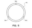
- the urging member 92 is an annular disc spring formed of metal, and as shown in FIG. 5, a plurality of protrusions 91p extending radially outward from the inner peripheral edge at intervals in the circumferential direction. , That is, in this embodiment, for example, three notches 92n at intervals of 120 °. Note that at least one protrusion 91p and notch 92n may be provided on the friction member 91 or the biasing member 92.
- Each protrusion 91p of the friction member 91 is fitted into a corresponding notch (or hole) 122n formed in the inner peripheral portion of the second intermediate plate member 122 of the intermediate member 12, whereby the friction member 91 is inserted into the second intermediate plate 122.
- the plate member 122 that is, the intermediate member 12 can be rotated integrally.
- a corresponding protrusion 91p of the friction member 91 is loosely fitted in each notch 92n between the inner peripheral portion of the second intermediate plate member 122 and the back surface of the washer portion 91a of the friction member 91. At the same time, it is arranged in a state of being crushed by a predetermined amount, and can be rotated integrally with the intermediate member 12.
- the friction member 91 is urged by the urging member 92 from the second intermediate plate member 122 side of the intermediate member 12 to the second input plate member 112 side of the drive member 11, and is opposite to the protrusion 91p of the washer portion 91a.
- the surface on the side is in pressure contact with the inner periphery of the second input plate member 112. Accordingly, a frictional force can be generated between the drive member 11 and the intermediate member 12 as the drive member 11 and the intermediate member 12 rotate relative to each other.
- the damper device 10 has a stopper (not shown) that restricts relative rotation between the drive member 11 and the driven member 15.
- the stopper restricts the relative rotation between the drive member 11 and the driven member 15, and accordingly, All the deflections of the first and second springs SP1, SP2 and the inner spring SPi are restricted.
- the damper device 10 includes a first torque transmission path TP1 including a plurality of first springs SP1, an intermediate member 12 and a plurality of second springs SP2, and a plurality of inner springs SPi.
- the rotary inertia mass damper 20 provided in parallel with both of the second torque transmission paths TP2 is included.
- the rotary inertia mass damper 20 includes a single-pinion planetary gear 21 disposed between a drive member 11 that is an input element of the damper device 10 and a driven member 15 that is an output element.
- the planetary gear 21 rotates a driven member 15 that functions as a sun gear including outer teeth 15t on the outer periphery, and a plurality of (for example, three in this embodiment) pinion gears 23 that mesh with the outer teeth 15t.
- the first and second input plate members 111 and 112 that function freely as a carrier and have inner teeth 25t that mesh with the pinion gears 23 and are arranged concentrically with the driven member 15 (outer teeth 15t) as a sun gear.
- the ring gear 25 is configured.
- the driven member 15 as the sun gear, the plurality of pinion gears 23 and the ring gear 25 are axially aligned with the first and second springs SP1 and SP2 (and the inner spring SPi) in the fluid chamber 9 as viewed from the radial direction of the damper device 10. At least partially overlap.
- the external teeth 15t are formed at a plurality of locations that are defined on the outer peripheral surface of the driven member 15 at intervals (equal intervals) in the circumferential direction. Therefore, the outer teeth 15t are more than the outer spring accommodating window 15wo and the inner spring accommodating window 15wi, that is, the first spring SP1, the second spring SP2, and the inner spring SPi that transmit torque between the drive member 11 and the driven member 15. Located radially outside.
- the external teeth 15t may be formed on the entire outer periphery of the driven member 15.
- the first input plate member 111 constituting the carrier of the planetary gear 21 is spaced radially in the circumferential direction from the outer spring accommodating window 111wo (outer spring contact portion) (etc.).
- a plurality of (for example, three in this embodiment) pinion gear support portions 115 arranged at intervals are provided.
- the second input plate member 112 that constitutes the carrier of the planetary gear 21 is also spaced radially outward from the outer spring accommodating window 112wo (outer spring contact portion) in the circumferential direction.
- a plurality of (for example, three in this embodiment) pinion gear support portions 116 arranged at regular intervals.
- each pinion gear support portion 115 of the first input plate member 111 has an arc-shaped protruding portion 115a formed so as to protrude toward the front cover 3, and a diameter from the end portion of the protruding portion 115a. And an arcuate flange portion 115f extending outward in the direction.
- each pinion gear support portion 116 of the second input plate member 112 has an arc-shaped protruding portion 116a formed so as to protrude toward the turbine runner 5 side, and extends radially outward from the end portion of the protruding portion 116a. Arc-shaped flange portion 116f.
- Each pinion gear support portion 115 (flange portion 115 f) of the first input plate member 111 is axially opposed to the corresponding pinion gear support portion 116 (flange portion 116 f) of the second input plate member 112 and forms a pair with each other. 115f and 116f support the end of the pinion shaft 24 inserted through the pinion gear 23, respectively.
- the pinion gear support portion 115 (flange portion 115f) of the first input plate member 111 is fastened to the clutch drum 81 of the lockup clutch 8 via a rivet.
- the first intermediate plate member 121 constituting the intermediate member 12 is aligned by the inner peripheral surface of the overhanging portion 115 a of the pinion gear support portion 115.
- the second intermediate plate member 122 constituting the intermediate member 12 is aligned by the inner peripheral surface of the projecting portion 116 a of the pinion gear support portion 116.
- the pinion gear 23 of the planetary gear 21 includes an annular gear main body 230 having gear teeth (external teeth) 23 t on the outer periphery, an inner peripheral surface of the gear main body 230, and an outer peripheral surface of the pinion shaft 24. And a pair of spacers 232 that are fitted to both ends of the gear body 230 and restrict movement of the needle bearing 231 in the axial direction.
- the gear body 230 of the pinion gear 23 protrudes to both sides in the axial direction of the gear teeth 23t on the inner peripheral side in the radial direction of the pinion gear 23 from the bottom of the gear teeth 23t and has a cylindrical surface shape.
- annular radial support portion 230s having an outer peripheral surface is included. Further, the outer peripheral surface of each spacer 232 is formed to have the same diameter as the radial support portion 230s or a smaller diameter than the radial support portion 230s.
- the plurality of pinion gears 23 are rotatably supported by first and second input plate members 111 and 112 (pinion gear support portions 115 and 116) as carriers so as to be arranged at regular intervals (equal intervals) in the circumferential direction. . Furthermore, a washer 235 is disposed between the side surface of each spacer 232 and the pinion gear support portions 115 and 116 (flange portions 115f and 116f) of the first and second input plate members 111 and 112. Further, between the side surfaces on both sides of the gear teeth 23t of the pinion gear 23 and the pinion gear support portions 115 and 116 (flange portions 115f and 116f) of the first and second input plate members 111 and 112 in the axial direction, FIG. A gap is formed as shown in FIG.
- the ring gear 25 of the planetary gear 21 includes an annular gear body 250 having inner teeth 25t formed on the inner periphery, two side plates 251 each formed in an annular shape, and each side plate 251 in the axial direction of the gear body 250. And a plurality of rivets 252 for fixing to both side surfaces.
- the gear body 250, the two side plates 251 and the plurality of rivets 252 are integrated to function as an inertia mass body (mass body) of the rotary inertia mass damper 20.
- the internal teeth 25t are formed over the entire inner peripheral surface of the gear body 250.
- the inner teeth 25t may be formed at a plurality of locations that are spaced apart (equally spaced) in the circumferential direction on the inner circumferential surface of the gear body 250.
- Each side plate 251 has a concave cylindrical surface-like inner peripheral surface and functions as a supported portion supported in the axial direction by a plurality of pinion gears 23 meshing with the inner teeth 25t. That is, the two side plates 251 protrude on the both sides in the axial direction of the inner teeth 25t in the radial direction from the roots of the inner teeth 25t and face at least the side surfaces of the gear teeth 23t of the pinion gear 23. It is fixed to 250 corresponding side surfaces.
- the inner peripheral surface of each side plate 251 is located slightly radially inward from the tooth tips of the inner teeth 25t.
- each side plate 251 When the pinion gears 23 and the inner teeth 25t mesh with each other, the inner peripheral surface of each side plate 251 is supported in the radial direction by the corresponding radial support portion 230s of the pinion gear 23 (gear body 230). As a result, the ring gear 25 can be smoothly rotated (oscillated) by accurately aligning the ring gear 25 with respect to the axis of the driven member 15 as the sun gear by the radial support portions 230 s of the plurality of pinion gears 23. .
- the inner surfaces of the side plates 251 face the side surfaces of the gear teeth 23t of the pinion gear 23 and the side surfaces of the portions from the tooth bottom of the gear teeth 23t to the radial support portion 230s. To do.
- the movement of the ring gear 25 in the axial direction is restricted by at least the side surfaces of the gear teeth 23t of the pinion gear 23.
- the gap between the outer surface of each side plate 251 of the ring gear 25 and the pinion gear support portions 115 and 116 (flange portions 115f and 116f) of the first and second input plate members 111 and 112 in the axial direction is shown in FIG. Thus, a gap is formed.
- the torque (power) transmitted from the engine EG to the front cover 3 is the pump. It is transmitted to the input shaft IS of the transmission TM through a path of the impeller 4, the turbine runner 5, and the damper hub 7.
- the torque transmitted from the engine EG to the drive member 11 via the front cover 3 and the lockup clutch 8 is the input torque described above.
- the first torque transmission path TP1 including the plurality of first springs SP1, the intermediate member 12, and the plurality of second springs SP2 while the torsion angle of the drive member 11 with respect to the driven member 15 is less than the predetermined angle ⁇ ref that is less than the torque T1. And transmitted to the driven member 15 and the damper hub 7 via the rotary inertia mass damper 20.
- the torque transmitted to the drive member 11 is the first torque transmission path TP1
- the second torque transmission path TP2 including the plurality of inner springs SPi, and the rotary inertia mass damper. 20 to the driven member 15 and the damper hub 7.
- the first and second springs SP1 and SP2 are bent and the drive member
- the ring gear 25 as a mass body rotates (oscillates) around the axis according to relative rotation between the motor 11 and the driven member 15.
- the drive member 11 rotates (swings) with respect to the driven member 15, the drive member 11 as a carrier that is an input element of the planetary gear 21, that is, the first and second input plate members 111 and 112.
- the rotational speed becomes higher than the rotational speed of the driven member 15 as the sun gear.
- the ring gear 25 is accelerated by the action of the planetary gear 21 and rotates at a higher rotational speed than the drive member 11.
- inertia torque is applied from the ring gear 25 which is the mass body of the rotary inertia mass damper 20 to the driven member 15 which is the output element of the damper device 10 via the pinion gear 23, and the vibration of the driven member 15 is attenuated.
- the rotary inertia mass damper 20 mainly transmits inertia torque between the drive member 11 and the driven member 15 and does not transmit average torque.
- the torque transmitted to the driven member 15 depends (proportional) on the displacement (deflection amount, that is, the twist angle) of the second spring SP2 between the intermediate member 12 and the driven member 15.
- the torque transmitted from the rotary inertia mass damper 20 to the driven member 15 is the difference in angular acceleration between the drive member 11 and the driven member 15, that is, the first and the second between the drive member 11 and the driven member 15. This is dependent (proportional) on the second derivative of the displacement of the second springs SP1 and SP2.
- the two natural frequencies are set to the state in which the first and second springs SP ⁇ b> 1 and SP ⁇ b> 2 are allowed to be bent and the inner spring SPi is not bent. Can be set. That is, when it is assumed that torque transmission from the engine EG to the drive member 11 is started in a state where the lock-up clutch 8 performs lock-up, the first and second springs SP1 in the first torque transmission path TP1. , SP2 is allowed to be deflected, and when the inner spring SPi is not bent, the drive member 11 and the driven member 15 resonate with each other in the opposite phase or resonance between the drive member 11 and a drive shaft (not shown). The resonance that occurs mainly occurs in the transmission (first resonance, see resonance point R1 in FIG. 7B).
- the intermediate member 12 of the first torque transmission path TP1 is formed in an annular shape, and when torque from the engine EG is transmitted to the drive member 11, inertial force that acts on the intermediate member 12 is applied to the intermediate member 12. It becomes larger than the resistance force that prevents the vibration (friction force mainly caused by the centrifugal force acting on the rotating intermediate member 12). Therefore, the damping ratio ⁇ of the intermediate member 12 that vibrates as the torque from the engine EG is transmitted to the drive member 11 is less than 1.
- the moment of inertia of the member 12, “k 1 ” is a combined spring constant of the plurality of first springs SP 1 acting in parallel between the drive member 11 and the intermediate member 12, and “k 2 ” is the intermediate member 12 is a composite spring constant of the plurality of second springs SP2 acting in parallel between the driven member 15 and the driven member 15, and “C” is a damping force (resistance) per unit speed of the intermediate member 12 that prevents the vibration of the intermediate member 12. That is, the damping ratio ⁇ of the intermediate member 12 is determined based on at least the moment of inertia J 2 of the intermediate member 12 and the stiffnesses k 1 and k 2 of the first and second springs SP1 and SP2.
- the intermediate member 12 is moved to the drive member 11 and the driven member. As a result, the intermediate member 12 resonates (the second resonance, see the resonance point R2 in FIG. 7B).
- the amplitude of the vibration transmitted from the first torque transmission path TP1 (second spring SP2) to the driven member 15 is the rotational speed of the engine EG (of the drive member 11), as shown by a one-dot chain line in FIG.
- the rotational speed) starts to decrease and increases before reaching the rotational speed corresponding to the natural frequency of the relatively small intermediate member 12.
- the amplitude of the vibration transmitted from the rotary inertia mass damper 20 to the driven member 15 is the rotational speed of the engine EG (the rotational speed of the drive member 11) as shown by a two-dot chain line in FIG. As the number increases, it gradually increases.
- the damper device 10 two peaks, that is, resonances (R1, R2) are generated in the torque transmitted through the first torque transmission path TP1 due to the presence of the intermediate member 12, FIG. as shown by a solid line in a), it is possible to vibration amplitude theta 3 of the driven member 15 is a total of two sets of anti-resonance point A1, A2 becomes theoretically zero. Therefore, the vibration damping performance of the damper device 10 can be improved by bringing the frequencies of the two anti-resonance points A1 and A2 closer to the frequency of the vibration (resonance) to be damped by the damper device 10.
- the vibration system including the damper device 10 of the present embodiment in which torque is transmitted from the engine EG to the drive member 11 by performing lock-up and the inner spring SPi is not bent is expressed by the following formula (1 ) Can be constructed.
- Equation (1) “J 1 ” is the moment of inertia of the drive member 11, “J 2 ” is the moment of inertia of the intermediate member 12 as described above, and “J 3 ” is the driven member. 15, and “J i ” is the moment of inertia of the ring gear 25 that is the mass body of the rotary inertia mass damper 20.
- ⁇ 1 is the twist angle of the drive member 11
- ⁇ 2 is the twist angle of the intermediate member 12
- ⁇ 3 is the twist angle of the driven member 15.
- ⁇ is the gear ratio of the planetary gear 21 constituting the rotary inertia mass damper 20 (pitch circle diameter of the outer teeth 15t (sun gear) / pitch circle diameter of the inner teeth 25t of the ring gear 25), that is, the driven member 15 It is a ratio of the rotational speed of the ring gear 25 as a mass body to the rotational speed.
- ⁇ 1 is the amplitude of vibration of the drive member 11 (vibration amplitude, that is, the maximum torsion angle) caused by transmission of torque from the engine EG
- ⁇ 2 is the engine EG in the drive member 11.
- vibration amplitude (vibration amplitude) of the intermediate member 12 generated when the torque from the engine EG is transmitted
- ⁇ 3 is generated as the torque from the engine EG is transmitted to the drive member 11. This is the amplitude of vibration of the driven member 15 (vibration amplitude).
- Equation (3) is a quadratic equation for the square value ⁇ 2 of the angular frequency in the periodic fluctuation of the input torque T.
- the two solutions ⁇ 1 and ⁇ 2 of the above equation (3) can be obtained from the formula of the solution of the quadratic equation, and ⁇ 1 ⁇ 2 is established.
- the frequency (hereinafter referred to as “minimum frequency”) fa 1 of the anti-resonance point A1 on the low rotation side (low frequency side) is expressed as shown in the following equation (4), and the high rotation side (high frequency side)
- the frequency fa 2 (fa 2 > fa 1 ) at the anti-resonance point A2 is expressed as shown in the following equation (5).
- the lockup speed Nlup of the lockup clutch 8 that is the speed at which the engine EG and the damper device 10 are first connected (the highest among the plurality of lockup speeds).
- Low spring and the frequencies fa 1 and fa 2 , the combined spring constant k 1 of the plurality of first springs SP 1 , the combined spring constant k 2 of the plurality of second springs SP 2 , the moment of inertia J 2 of the intermediate member 12, Then, the moment of inertia J i of the ring gear 25 which is the mass body of the rotary inertia mass damper 20 is selected and set. Thereby, the vibration damping performance of the damper device 10 can be further improved.
- the lock-up rotational speed Nlup of the lockup clutch 8 a predetermined rotational speed range centered on the rotational speed Nea 1 corresponding to the frequency of the antiresonance point A1 of the low-rotation (minimum frequency fa 1) (e.g. Nea 1 ⁇ 500 rpm ⁇ Nloop ⁇ Nea 1 +500 rpm). That is, as shown in FIG.
- the lockup rotation speed Nlup may be set lower than the rotation speed Nea 1 of the engine EG corresponding to the vibration frequency at the anti-resonance point A1 on the low rotation side, and the rotation speed Nea 1 May be set to a value in the vicinity of the rotational speed Nea 1 (for example, Ne 1 ⁇ 100 rpm ⁇ Nloop ⁇ Nea 1 +100 rpm). Further, in the present embodiment, the lock-up rotational speed Nlup, as shown in FIG.
- the resonance speed at the resonance point R1 (resonance at the smaller of the two natural frequencies) becomes a virtual one that does not occur in the rotation speed region where the damper device 10 is used.
- the damper device 10 is provided with a damping mechanism 90 that generates a frictional force between the drive member 11 and the intermediate member 12 as described above in order to attenuate the resonance (R2) of the intermediate member 12. ing. Accordingly, as shown by a solid line in FIG. 7A, the resonance amplitude of the intermediate member 12 is suppressed from increasing, and the inertial torque transmitted from the rotary inertia mass damper 20 to the driven member 15 is reduced. The vibration level in the vicinity of the resonance point R2 and the anti-resonance point A2 on the high rotation side can be satisfactorily reduced (see the solid line in FIG. 7A). As a result, in the damper device 10, the vibration damping performance can be further improved by appropriately selecting the dynamic friction coefficient of the friction member 91 (washer portion 91 a) and the rigidity of the biasing member (disc spring) 92.
- the rotational speed of the drive member 11 is low.
- Resonance of the intermediate member 12 occurs at a stage where the rotational speed Ne 1 corresponding to the frequency fa 1 of the anti-resonance point A1 on the side (low frequency side) is increased. Therefore, by providing the damper device 10 with the damping mechanism 90 that attenuates the resonance of the intermediate member 12, the vibration level in the vicinity of the resonance point R2 of the intermediate member 12 and the anti-resonance point A2 on the high rotation side (high circumferential side) can be further increased. It becomes possible to reduce well.
- the damping mechanism 90 that generates the frictional force between the drive member 11 and the intermediate member 12 as in the above embodiment, the frictional force is generated between the drive member 11 and the intermediate member 12.
- the friction member 91 and the biasing member 92 rotate integrally with the intermediate member 12, and the second input plate member 112 of the drive member 11 and the second intermediate plate member of the intermediate member 12.
- the present invention is not limited to this. That is, the friction member 91 and the biasing member 92 are disposed between the second input plate member 112 of the drive member 11 and the second intermediate plate member 122 of the intermediate member 12 so as to rotate integrally with the drive member 11. May be.
- the sun gear of the planetary gear 21 may be connected (integrated) to the drive member 11, and the driven member 15 may be configured as a carrier for the planetary gear 21.
- FIG. 8 is an enlarged cross-sectional view showing another damper device 10B of the present disclosure.
- the damper device 10B shown in FIG. 8 includes a damping mechanism 95 that generates frictional force between the intermediate member 12B and the driven member 15B to attenuate the resonance of the intermediate member 12B.
- a portion located radially inward from a portion corresponding to the inner spring accommodating window 111wi is omitted from the first input plate member 111B of the drive member 11B.
- the friction member 96 and the biasing member 97 of the damping mechanism 95 are disposed between the inner peripheral portion of the first intermediate plate member 121B of the intermediate member 12B and the inner peripheral portion of the driven member 15B in the axial direction.
- the friction member 96 is also formed of resin, for example, and as shown in FIG. 8, protrudes in the axial direction with a flat and annular washer portion 96a and a circumferential surface spaced from one surface of the washer portion 96a.
- a plurality of projections 96p (for example, three at intervals of 120 °).
- the biasing member 97 is also an annular disc spring formed of metal, and a plurality of (three as the projections 96p, for example, three at 120 ° intervals) extend radially outward from the inner peripheral edge at intervals in the circumferential direction. ) Notch (not shown).
- Each protrusion 96p of the friction member 96 is fitted into a corresponding notch (or hole) 121n formed in the inner peripheral portion of the first intermediate plate member 121B of the intermediate member 12B, whereby the friction member 96 is connected to the first intermediate plate member 121B. It becomes possible to rotate integrally with the plate member 121B, that is, the intermediate member 12B. Further, in the biasing member 97, a corresponding projection 96p of the friction member 96 is loosely fitted in each notch between the inner peripheral portion of the first intermediate plate member 121B and the back surface of the washer portion 96a of the friction member 96. It is arranged in a state where it is crushed by a predetermined amount, and can rotate integrally with the intermediate member 12B.
- the friction member 96 is urged from the first intermediate plate member 121B side of the intermediate member 12B to the driven member 15B side by the urging member 97, and the surface of the washer portion 96a opposite to the projection 96p is the driven member 15B. Press contact with the inner periphery of the. Also with the damping mechanism 95, as the intermediate member 12B and the driven member 15B rotate relative to each other, a frictional force is generated between them to appropriately attenuate the resonance of the intermediate member 12B.
- the friction member 96 and the biasing member 97 are disposed between the first intermediate plate member 121B of the intermediate member 12B and the driven member 15B so as to rotate integrally with the driven member 15B. May be.
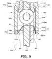
- FIG. 9 is an enlarged cross-sectional view showing still another damper device 10C of the present disclosure. Note that, among the components of the damper device 10C, the same components as those of the above-described damper devices 10 and 10B are denoted by the same reference numerals, and redundant description is omitted.
- the damper device 10C shown in FIG. 9 generates damping force between the second input plate member 112 of the drive member 11C and the second intermediate plate member 122 of the intermediate member 12C to attenuate the resonance of the intermediate member 12C.
- a damping mechanism (second damping mechanism) that attenuates resonance of the intermediate member 12C by generating a frictional force between the mechanism (first damping mechanism) 90 and the first intermediate plate member 121C and the driven member 15C of the intermediate member 12C. 95 and both.
- the first input plate member 111C of the drive member 11C is the same as the first input plate member 111B of the drive member 11B described above.
- the friction member (first friction member) 91 is moved from the second intermediate plate member 122 side of the intermediate member 12C by the biasing member (first biasing member) 92 to the second input plate member of the drive member 11C.
- the surface of the washer portion 91 a opposite to the protrusion 91 p is pressed against the inner peripheral portion of the second input plate member 112.
- the friction member (second friction member) 96 is urged by the urging member (second urging member) 97 from the first intermediate plate member 121C side of the intermediate member 12C to the driven member 15C side, and the washer portion 96a.
- the surface opposite to the protrusion 96p is in pressure contact with the inner peripheral portion of the driven member 15C.
- the frictional force is generated both between the drive member 11C and the intermediate member 12C and between the intermediate member 12C and the driven member 15C. It is possible to properly attenuate the resonance of the intermediate member 12C.
- the friction member 91 and the biasing member 92 are second intermediate between the second input plate member 112 and the intermediate member 12C of the drive member 11C so as to rotate integrally with the drive member 11C. You may arrange
- the friction member 96 and the biasing member 97 are arranged between the first intermediate plate member 121C of the intermediate member 12C and the driven member 15C so as to rotate integrally with the driven member 15C. May be.
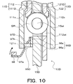
- FIG. 10 is an enlarged cross-sectional view showing another damper device 10D of the present disclosure.
- a damper device 10D shown in FIG. 10 includes a damping mechanism 95D that attenuates the resonance of the intermediate member 12D while changing the frictional force between the intermediate member 12D and the driven member 15D according to the rotational speed of the drive member 11D.
- the first input plate member 111D of the drive member 11D is the same as the first input plate member 111B of the drive member 11B described above.
- the friction member 96D and the biasing member 97D of the damping mechanism 95D are disposed between the inner peripheral portion of the first intermediate plate member 121D of the intermediate member 12D and the inner peripheral portion of the driven member 15D in the axial direction.
- the friction member 96D is also made of, for example, resin, and has a flat plate-like and annular washer portion 96a and a plurality of (for example, 120 ° intervals) protruding in the axial direction at intervals from one surface of the washer portion 96a. 3) projections 96p.
- the urging member 97D is an annular disc spring formed of metal and has an inner diameter smaller than that of the urging member 97 shown in FIG.
- the urging member 97D includes a plurality of (for example, four at 90 ° intervals) extending portions 97e extending in the axial direction on the opposite side of the outer peripheral portion at intervals from the inner peripheral portion, A plurality of openings 97h (the same number as the projections 96p, for example, three at intervals of 120 °) are provided on the radially outer side with respect to the extending portion 97e with a spacing in the circumferential direction. Further, a mass body 98 is fixed to the radially outer surface of each extending portion 97e of the urging member 97D as shown in the drawing.
- each protrusion 96p of the friction member 96D is fitted into a corresponding notch (or hole) 121n formed in the inner peripheral portion of the first intermediate plate member 121D of the intermediate member 12D, and thereby the friction member 96D.
- the biasing member 97D is in a state in which the corresponding protrusion 96p of the friction member 96D is loosely fitted in each opening 97h between the inner peripheral portion of the first intermediate plate member 121D and the back surface of the washer portion 96a of the friction member 96D. It arrange
- the urging member 97D has an outer peripheral portion that abuts against the back surface of the washer portion 96a of the friction member 96D, and a radially outer portion (near the opening 97h) than each extending portion 97e ) Comes into contact with the inner peripheral portion of the first intermediate plate member 121D and is slightly crushed. Further, the inner peripheral portion of each biasing member 97D, each extending portion 97e, and each mass body 98 are located radially inward (center side) with respect to the inner peripheral edge portion of the first intermediate plate member 121D. The member 97D is separated from the washer portion 96a of the friction member 96D in the axial direction of the damper device 10D rather than the contact portion (fulcrum) of the member 97D with the first intermediate plate member 121D.
- each mass body 98 (and the extending portion 97e) moves radially outward by centrifugal force. It moves and approaches the washer part 96a of the friction member 96D (see the solid line arrow in FIG. 10).
- the friction member 96D is urged toward the driven member 15D from the first intermediate plate member 121D side of the intermediate member 12D by the urging member 97D.
- the surface opposite to the projection 96p is strongly pressed against the inner peripheral portion of the driven member 15D as the rotational speed of the drive member 11D increases.
- the frictional force between the intermediate member 12D and the driven member 15D can be increased as the rotational speed of the drive member 11D increases.
- the frictional force generated when the rotational speed of the drive member 11D is low can be reduced, the phase of vibration transmitted from the drive member 11D to the driven member 15D is shifted with the generation of the frictional force. It is possible to attenuate the resonance of the intermediate member 12D very well while suppressing the above.
- the damping mechanism 95D may be configured to generate a frictional force between the drive member 11D and the intermediate member 12D. Further, the damper device 10D may be additionally provided with a damping mechanism that attenuates the resonance of the intermediate member 12D while changing the frictional force between the drive member 11D and the intermediate member 12D.
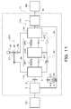
- FIG. 11 is a schematic configuration diagram illustrating a starter device 1X including still another damper device 10X according to the present disclosure. Note that among the components of the starting device 1X and the damper device 10X, the same elements as those of the above-described starting device 1 and the damper device 10 are denoted by the same reference numerals, and redundant description is omitted.
- the damper device 10X corresponds to a plurality of first springs (first elastic bodies) SP1 that transmit torque between the drive member 11X and the intermediate member 12X as torque transmitting elements (torque transmitting elastic bodies), respectively.
- a plurality of second springs (second elastic bodies) SP2 that act in series with the first spring SP1 and transmit torque between the intermediate member 12X and the driven member 15X are included.
- the plurality of first springs (first elastic bodies) SP1, the intermediate member 12X, and the plurality of second springs (second elastic bodies) SP2 constitute a torque transmission path TP between the drive member 11X and the driven member 15X.
- the damper device 10 ⁇ / b> X includes a rotary inertia mass damper 20 ⁇ / b> X configured by a single pinion type planetary gear 21 like the rotary inertia mass damper 20.
- the rotary inertia mass damper 20X is provided in parallel with the torque transmission path TP between the drive member 11X and the driven member 15X.
- the drive member 11X functions as a carrier for the planetary gear 21 by rotatably supporting a plurality of pinion gears 23, and the driven member 15X has external teeth 15t and serves as the sun gear of the planetary gear 21. Function.
- the damper device 10X has a relative rotation between the drive member 11X and the intermediate member 12X, that is, a first stopper ST1 that restricts the bending of the first spring SP1, and a relative rotation between the intermediate member 12X and the driven member 15X, that is, a second rotation. And a second stopper ST2 for restricting the bending of the spring SP2.
- One of the first and second stoppers ST1, ST2 reaches a predetermined torque T1 in which the input torque to the drive member 11X is smaller than the torque T2 corresponding to the maximum torsion angle ⁇ max of the damper device 10X, and the drive member 11X
- the twist angle with respect to the driven member 15X becomes equal to or larger than the predetermined angle ⁇ ref
- the relative rotation between the drive member 11X and the intermediate member 12X or the relative rotation between the intermediate member 12X and the driven member 15X is restricted.
- the other of the first and second stoppers ST1 and ST2 is the relative rotation of the intermediate member 12X and the driven member 15X or the drive member 11X and the intermediate member 12X.
- the relative rotation of the is regulated.
- the damper device 10X also has a two-stage (two-stage) attenuation characteristic.
- the first or second stoppers ST1 and ST2 may be configured to restrict relative rotation between the drive member 11X and the driven member 15X.
- a damping mechanism 90 that generates frictional force between the drive member 11X and the intermediate member 12X to attenuate the resonance of the intermediate member 12X is provided.
- the damper device 10X is provided with a damping mechanism 95 that generates frictional force between the intermediate member 12X and the driven member 15X to attenuate the resonance of the intermediate member 12X, as indicated by a two-dot chain line in the drawing.
- both damping mechanisms 90 and 95 may be provided.
- the damper device 10X includes a damping mechanism that attenuates resonance of the intermediate member 12X while changing the frictional force between the drive member 11X and the intermediate member 12X, and friction between the intermediate member 12X and the driven member 15X. At least one of a damping mechanism that attenuates resonance of the intermediate member 12X while changing the force may be provided.
- any one of the first and second springs SP1 and SP2 may be arranged so as to be arranged at intervals in the circumferential direction on the other radial outside. That is, for example, the plurality of first springs SP1 may be arranged in the outer peripheral side region in the fluid chamber 9 so as to be arranged at intervals in the circumferential direction.
- the plurality of second springs SP2 are arranged in the plurality of first springs SP1. They may be arranged so as to be arranged at intervals in the circumferential direction on the radially inner side. In this case, the first and second springs SP1 and SP2 may be arranged so as to overlap at least partially when viewed from the radial direction.
- the sun gear of the planetary gear 21 may be connected (integrated) to the drive member 11X, and the driven member 15X may be configured as a carrier for the planetary gear 21.
- FIG. 12 is a schematic configuration diagram illustrating a starter device 1Y including another damper device 10Y of the present disclosure. Note that among the components of the starting device 1Y and the damper device 10Y, the same elements as those of the above-described starting device 1 and the damper device 10 are denoted by the same reference numerals, and redundant description is omitted.
- a damper device 10Y shown in FIG. 12 includes a drive member (input element) 11Y, a first intermediate member (first intermediate element) 13, a second intermediate member (second intermediate element) 14, and a driven member as rotating elements. (Output element) 15Y. Further, the damper device 10Y includes a plurality of first springs (first elastic bodies) SP1 ′ that transmit torque between the drive member 11Y and the first intermediate member 13 as torque transmitting elements (torque transmitting elastic bodies); Torque is transmitted between the plurality of second springs (second elastic bodies) SP2 'that transmit torque between the first intermediate member 13 and the second intermediate member 14, and between the second intermediate member 14 and the driven member 15Y. And a plurality of third springs (third elastic bodies) SP3.
- a plurality of first springs (first elastic bodies) SP1 ′, a first intermediate member 13, a plurality of second springs (second elastic bodies) SP2 ′, a second intermediate member 14, and a plurality of third springs SP3 are drive members.
- a torque transmission path TP is configured between 11Y and the driven member 15Y.
- the damper device 10 ⁇ / b> Y includes a rotary inertia mass damper 20 ⁇ / b> Y configured by a single pinion type planetary gear 21 like the rotary inertia mass damper 20.
- the rotary inertia mass damper 20Y is provided in parallel with the torque transmission path TP between the drive member 11Y and the driven member 15Y.
- a damping mechanism 90 that attenuates the resonance of the first intermediate member 13 by generating a frictional force between the drive member 11Y and the first intermediate member 13 with respect to the damper device 10Y.
- the damper device 10Y has a damping mechanism that generates a frictional force between the first intermediate member 13 and the driven member 15Y to attenuate the resonance of the first intermediate member 13 as indicated by a two-dot chain line in the figure. 95 may be provided, and both damping mechanisms 90 and 95 may be provided.
- the damper device 10Y may be provided with a damping mechanism that generates a frictional force between the first and second intermediate members 13 and 14.
- the damper device 10Y includes a damping mechanism that attenuates resonance of the first intermediate member 13 while changing the frictional force between the drive member 11Y and the first intermediate member 13, and the first intermediate member 13 and the driven member.
- There may be provided at least one of a damping mechanism for damping the resonance of the first intermediate member 13 while changing the frictional force with the 15Y.
- the damper device 10Y may be provided with a damping mechanism that attenuates resonance of the second intermediate element.
- the damper device 10Y may be configured to include three or more intermediate members in the torque transmission path TP.
- the sun gear of the planetary gear 21 may be connected (integrated) to the drive member 11Y, and the driven member 15Y may be configured as a carrier for the planetary gear 21.
- the sun gear of the planetary gear 21 may be connected (integrated) to the first intermediate member 13, and for example, the first intermediate member 13 may be configured as a carrier for the planetary gear 21.
- FIG. 13 is a schematic configuration diagram showing a starter device 1Z including still another damper device 10Z of the present disclosure. Note that among the components of the starting device 1Z and the damper device 10Z, the same elements as those of the above-described starting device 1 and the damper device 10 are denoted by the same reference numerals, and redundant description is omitted.
- a damper device 10Z shown in FIG. 13 includes, as rotating elements, a drive member (input element) 11Z, a first intermediate member (first intermediate element) 13, a second intermediate member (second intermediate element) 14, and a driven member. (Output element) 15Z. Further, the damper device 10Z includes a plurality of first springs (first elastic bodies) SP1 ′ that transmit torque between the drive member 11 and the first intermediate member 13Z as torque transmission elements (torque transmission elastic bodies); Torque is transmitted between the plurality of second springs (second elastic bodies) SP2 'that transmit torque between the first intermediate member 13Z and the second intermediate member 14Z, and between the second intermediate member 14Z and the driven member 15Z. And a plurality of third springs (third elastic bodies) SP3.
- the plurality of first springs (first elastic bodies) SP1 ′, the first intermediate member 13Z, the plurality of second springs (second elastic bodies) SP2 ′, the second intermediate member 14Z, and the plurality of third springs SP3 are drive members.
- a torque transmission path TP is configured between 11Z and the driven member 15Z.
- the damper device 10 ⁇ / b> Z includes a rotary inertia mass damper 20 ⁇ / b> Z configured by a single pinion type planetary gear 21, similar to the rotary inertia mass damper 20.
- the rotary inertia mass damper 20Z is provided between the drive member 11Z and the second intermediate member 14Z in parallel with the first spring SP1 ′, the first intermediate member 13Z, and the second spring SP2 ′ of the torque transmission path TP.
- the drive member 11Z functions as a carrier for the planetary gear 21 by rotatably supporting a plurality of pinion gears 23, and the second intermediate member 14Z has external teeth 14t. Functions as a sun gear.
- the ring gear 25 as a mass body rotates (swings) about the axis according to the relative rotation between the drive member 11Z and the second intermediate member 14Z.
- the damper device 10Z is substantially equivalent to the damper device 10X shown in FIG. 11 in which a plurality of third springs SP3 acting in parallel are arranged between the driven member 15X and the input shaft IS of the transmission TM. To do.
- the rotary inertia mass damper 20Z is provided in parallel with the first and second springs SP1 ′, SP2 ′ and the first intermediate member 13Z. Accordingly, in the damper device 10Z, two (plural) are provided for the torque transmission path from the drive member 11Z to the second intermediate member 14Z in a state where at least the bending of the first and second springs SP1 ′ and SP2 ′ is allowed.
- the resonance (second resonance) of the first intermediate member 13Z can be generated on the higher rotation side (high frequency side) than the first resonance.
- the damper device 10Z it is possible to set a total of two anti-resonance points where the vibration amplitude of the driven member 15Z is theoretically zero.
- a frictional force is generated between the drive member 11Z and the first intermediate member 13Z to attenuate the resonance of the first intermediate member 13Z.
- the damping mechanism 90 that performs the same function and effect as those of the above-described damper device 10 and the like, it is possible to obtain the same effect.
- a frictional force is generated between the first intermediate member 13Z and the second intermediate member 14Z to attenuate the resonance of the first intermediate member 13Z.
- a damping mechanism 95 may be provided, or both damping mechanisms 90 and 95 may be provided.
- the damper device 10Z includes a damping mechanism that attenuates the resonance of the first intermediate member 13Z while changing the frictional force between the drive member 11Z and the first intermediate member 13Z, and the first intermediate member 13Z and the second intermediate member 13Z. At least one of a damping mechanism that attenuates the resonance of the first intermediate member 13Z while changing the frictional force with the intermediate member 14Z may be provided.
- the damper device 10Z is preferably used in combination with the transmission TM for driving the rear wheels. That is, the rear wheel drive transmission in which the length from the end of the input shaft IS (the end on the starting device 1Z side) to the end of the output shaft (not shown) of the transmission TM (the end on the wheel side) is increased.
- TM the rigidity of the input shaft IS and output shaft connected to the driven member 15Z of the damper device 10Z (and the intermediate shaft (not shown) of the transmission TM) is lowered, so that the inherent moment determined by the inertia moment of these shaft members is reduced.
- the frequency (resonance frequency) becomes smaller due to the influence of the moment of inertia of the entire rotary inertia mass damper 20Z (lower frequency). For this reason, there is a possibility that resonance that occurs originally when the rotational speed of the drive member 11 (engine EG) is high occurs in the low rotation range and becomes apparent.
- the third spring SP3 can be interposed between the shaft IS and both can be substantially separated.
- the damper device 10Z may be combined with the transmission TM for the front wheel drive vehicle. Even when the damper device 10Z and the transmission TM for a front wheel drive vehicle are combined, the influence of the inertia moment of the entire rotary inertia mass damper 20Z on the natural frequency determined from the inertia moment of the shaft member or the like connected to the driven member 15Z is reduced. It is possible to improve the vibration damping performance of the damper device 10Z by reducing the vibration very well and further reducing the rigidity. Further, the damper device 10Z may include a further intermediate member and a spring (elastic body) between the first intermediate member 13Z and the second intermediate member 14Z. Further, in the damper device 10Z, the sun gear of the planetary gear 21 may be connected (integrated) to the drive member 11Z, and the driven member 15Z may be configured as a carrier for the planetary gear 21.
- FIG. 14 is a schematic configuration diagram illustrating a starting device 1V including still another damper device 10V of the present disclosure.
- the same elements as those of the starting device 1 and the damper device 10 described above are denoted by the same reference numerals, and redundant description is omitted.
- a damper device 10V shown in FIG. 14 includes a rotary inertia mass damper 20 having a ring gear 25 as a mass body that rotates according to the relative rotation of the drive member 11 and the driven member 15 in the damper device 10 shown in FIG.
- the drive member 11V functions as a carrier for the planetary gear 21 by rotatably supporting a plurality of pinion gears 23, and the intermediate member 12V has external teeth 12t. Functions as a sun gear.
- the vibration transmitted from the drive member 11V to the intermediate member 12V via the first spring SP1 and the vibration transmitted from the drive member 11V to the intermediate member 12V via the rotary inertia mass damper 20V are theoretically. It is possible to set one anti-resonance point that will cancel each other. Also in the damper device 10V, the first and second springs SP1 and SP2 act in series between the drive member 11V and the driven member 15V, so that the combined spring constant of the first and second springs SP1 and SP2 Can be made smaller.
- the damper device 10V is provided with a damping mechanism 95 that generates a frictional force between, for example, the intermediate member 12V and the driven member 15V to attenuate the resonance of the intermediate member 12V.
- a damping mechanism 95 that generates a frictional force between, for example, the intermediate member 12V and the driven member 15V to attenuate the resonance of the intermediate member 12V.
- the vibration level in the vicinity of the resonance point of the intermediate member 12V can be satisfactorily reduced by the inertia torque transmitted from the rotary inertia mass damper 20V to the intermediate member 12V (driven member 15V). Further, by generating a frictional force between the intermediate member 12V and the driven member 15V to attenuate the resonance of the intermediate member 12V, the operation of the rotary inertia mass damper 20V between the drive member 11V and the intermediate member 12V is prevented. The influence of the frictional force can be reduced.
- the damper device 10V is provided with a damping mechanism 90 that attenuates the resonance of the intermediate member 12V by generating a frictional force between the drive member 11V and the intermediate member 12V, as indicated by a two-dot chain line in the figure.
- damping mechanisms 90 and 95 may be provided.
- the damper device 10V includes a damping mechanism that attenuates resonance of the intermediate member 12V while changing the frictional force between the drive member 11V and the intermediate member 12V, and friction between the intermediate member 12V and the driven member 15V.
- At least one of a damping mechanism that attenuates resonance of the intermediate member 12V while changing the force may be provided.
- the sun gear of the planetary gear 21 may be connected (integrated) to the drive member 11V, and the intermediate member 12V may be configured as a carrier for the planetary gear 21.
- the damper device includes the input element (11, 11B, 11C, 11D, 11X, 11Y) to which the torque from the engine (EG) is transmitted, and the intermediate element (12, 12B, 12C, 12D). , 12X, 13, 14), output elements (15, 15B, 15C, 15D, 15X, 15Y), first elastic bodies (SP1, SP1 ') for transmitting torque between the input elements and the intermediate elements, And a damper device (10, 10B, 10C, 10D, 10X, 10Y) including a second elastic body (SP2, SP2 ′, SP3) for transmitting torque between the intermediate element and the output element, the input element And a mass body (25) that rotates according to relative rotation between the first elastic body, the intermediate element, and the second element between the input element and the output element.
- a damper device (10, 10B, 10C, 10D, 10X, 10Y) including a second elastic body (SP2, SP2 ′, SP3) for transmitting torque between the intermediate element and the output element, the input element And
- a plurality of natural frequencies are set in a state where the bending of the first and second elastic bodies is allowed for the torque transmission path including the intermediate element, and the rotation of the input element
- the resonance of the intermediate element can be generated when the number reaches the number of rotations corresponding to any of the plurality of natural frequencies.
- the vibration damping performance of the damper device can be improved by bringing the frequencies of the two anti-resonance points closer to the frequency of the vibration (resonance) to be damped by the damper device.
- the damper device includes a damping mechanism that damps the resonance of the intermediate element. This suppresses an increase in the resonance amplitude of the intermediate member, and the vibration level near the resonance point of the intermediate member (the corresponding anti-resonance point) by the inertia torque transmitted from the rotary inertia mass damper to the output element. Can be satisfactorily reduced. As a result, the vibration damping performance of the damper device can be further improved.
- the damping mechanism (90, 95, 95D) includes at least one of the input element (11, 11B, 11C, 11D, 11X, 11Y) and the output element (15, 15B, 15C, 15D, 15X, 15Y).
- a frictional force may be generated between the intermediate element (12, 12B, 12C, 12D, 12X, 13). Thereby, the resonance of the intermediate element can be attenuated more appropriately.
- the damping mechanism (90, 95D) is a friction between the input element (11, 11B, 11C, 11D, 11X, 11Y) and the intermediate element (12, 12B, 12C, 12D, 12X, 13). It may generate a force. As a result, the frictional force generated between the input element and the intermediate element is prevented from shifting the phase of vibration transmitted from the input element to the output element via the torque transmission path. It becomes possible to attenuate the resonance well.
- the damping mechanism (90, 95D) is integrated with one of the input element (11, 11B, 11C, 11D, 11X, 11Y) and the intermediate element (12, 12B, 12C, 12D, 12X, 13).
- a rotating friction member (91, 96D) and a biasing member (92, 97D) for biasing the friction member from the one side to the other side of the input element and the intermediate element may be included. .
- damping mechanism (95, 95D) is integrated with one of the intermediate element (12, 12B, 12C, 12D, 12X, 13) and the output element (15, 15B, 15C, 15D, 15X, 15Y).
- a rotating friction member (96, 96D) and a biasing member (97, 97D) for biasing the friction member from the one side to the other side of the intermediate element and the output element may be included. .
- the damping mechanism includes a first friction member (91, 96D) that rotates integrally with one of the input element and the intermediate element, and the first friction member from the one side of the input element and the intermediate element.
- a second biasing member (97, 97D) that biases the intermediate element and the output element from the one side to the other side may be included.
- the damping mechanism (95D) may change the frictional force according to the rotational speed of the input elements (11, 11B, 11C, 11D, 11X, 11Y). , 11B, 11C, 11D, 11X, 11Y), the frictional force may be increased as the rotational speed increases. As a result, the frictional force generated when the rotational speed of the input element is low can be reduced, so that the phase of vibration transmitted from the input element to the output element via the torque transmission path is shifted as the frictional force is generated. It is possible to attenuate the resonance of the intermediate element very well while suppressing the occurrence of the interference.
- the damping ratio ( ⁇ ) of the intermediate element determined based on the moment of inertia (J 2 ) of the intermediate element and the rigidity (k 1 , k 2 ) of the first and second elastic bodies is less than 1.
- the rotational speed corresponding to the natural frequency (f 12 ) of the intermediate element is based on the minimum rotational speed (Nloop) in the rotational speed range in which torque is transmitted from the input element to the output element via the torque transmission path. May be higher.
- the resonance of the intermediate element occurs when the rotational speed of the input element is higher than the rotational speed corresponding to the frequency of the anti-resonance point on the low rotational side (low frequency side). Therefore, by providing the damper device with a damping mechanism for damping the resonance of the intermediate element, the vibration level near the anti-resonance point on the high rotation side (high circumferential side) can be reduced more favorably.
- output elements (15, 15B, 15C, 15D, 15X, 15Y) may be operatively connected to the input shaft (IS) of the transmission (TM).
- Another damper device of the present disclosure includes an input element (11Z) to which torque from the engine (EG) is transmitted, a first intermediate element (13Z), a second intermediate element (14Z), an output element (15Z), and the input Torque is transmitted between the first elastic element (SP1 ′) for transmitting torque between the element (11Z) and the first intermediate element (13Z), and the first and second intermediate elements (13Z, 14Z).
- the damper device (10Z) including the second elastic body (SP2 ′) and the third elastic body (SP3) for transmitting torque between the second intermediate element (14Z) and the output element (15Z), It has a mass body (25) that rotates in response to relative rotation between the input element (11Z) and the second intermediate element (14Z), and includes the first elastic body (SP1 ′) and the first intermediate element (13Z ), And a rotary inertia mass damper (20Z) provided in parallel with the second elastic body (SP2 '), and a damping mechanism (90, 95) for damping the resonance of the first intermediate element (13Z) It is.
- the third elastic body is provided between the rotary inertia mass damper and the member connected to the output element.
- both can be substantially separated. This makes it possible to set the two anti-resonance points and extremely well reduce the influence of the inertia moment of the entire rotary inertia mass damper on the natural frequency determined from the inertia moment of the member connected to the output element. it can.
- the damper device As a result, even if the rigidity of the member connected to the output element of the damper device is low, and the natural frequency (resonance frequency) determined from the inertia moment of the member is reduced due to the influence of the inertia moment of the entire rotary inertia mass damper, Originally, it is possible to satisfactorily suppress the occurrence of resonance in the low rotation region and manifesting it in a state where the rotational speed of the input element is high. Further, by providing the damper device with a damping mechanism for attenuating the resonance of the first intermediate element, it is possible to suppress an increase in the resonance amplitude of the first intermediate member and to transmit the inertia transmitted from the rotary inertia mass damper to the output element. The torque can satisfactorily reduce the vibration level in the vicinity of the resonance point (corresponding antiresonance point) of the first intermediate member. As a result, the vibration damping performance of the damper device can be further improved.
- Still another damper device of the present disclosure includes an input element (11V) to which torque from an engine (EG) is transmitted, an intermediate element (12V), an output element (15V), the input element (11V), and the intermediate element ( 12V), and a damper including a first elastic body (SP1) that transmits torque between the intermediate element (12V) and the output element (15V).
- the device (10V) includes a mass body (25) that rotates in response to relative rotation between the input element (11V) and the intermediate element (12V), and the input element (11V) and the intermediate element (12V).
- a rotary inertia mass damper (20V) provided in parallel with the first elastic body (SP1), and a damping mechanism (90) for damping the resonance of the intermediate element (12V).
- the damping mechanism attenuates the resonance of the intermediate member.
- the vibration level in the vicinity of the resonance point of the intermediate member can be satisfactorily reduced by the inertia torque transmitted from the rotary inertia mass damper to the intermediate member (driven member).
- the vibration damping performance of the damper device can be further improved.
- the invention of the present disclosure can be used in the field of manufacturing damper devices.
Landscapes
- Engineering & Computer Science (AREA)
- General Engineering & Computer Science (AREA)
- Mechanical Engineering (AREA)
- Physics & Mathematics (AREA)
- Acoustics & Sound (AREA)
- Aviation & Aerospace Engineering (AREA)
- Mechanical Operated Clutches (AREA)
Abstract
ダンパ装置は、エンジンからのトルクが伝達される入力要素と、中間要素と、出力要素と、入力要素と中間要素との間でトルクを伝達する第1弾性体と、中間要素と出力要素との間でトルクを伝達する第2弾性体と、入力要素と出力要素との相対回転に応じて回転する質量体を有し、入力要素と出力要素との間に、第1弾性体、中間要素および第2弾性体を含むトルク伝達経路と並列に設けられる回転慣性質量ダンパと、中間要素の共振を減衰する減衰機構とを含む。
Description
本開示の発明は、入力要素と出力要素との間でトルクを伝達する弾性体、および回転慣性質量ダンパを含むダンパ装置に関する。
従来、この種のダンパ装置として、ドライブ部材(入力要素)と中間部材(中間要素)との間でトルクを伝達する第1スプリングと、中間部材とドリブン部材(出力要素)の間でトルクを伝達する第2スプリングと、中間部材と第1および第2スプリングとを含むトルク伝達経路と並列に設けられると共にドライブ部材とドリブン部材との相対回転に応じて回転する質量体としてのサンギヤを有する回転慣性質量ダンパとを含むものが知られている(例えば、特許文献1)。かかるダンパ装置では、エンジンからドライブ部材に伝達される入力トルクが周期的に振動していると仮定すれば、ドライブ部材から上記トルク伝達経路を介してドリブン部材に伝達される振動の位相と、ドライブ部材から回転慣性質量ダンパを介してドリブン部材に伝達される振動の位相とが180°ずれることになる。また、このダンパ装置では、中間部材の慣性モーメントと第1および第2スプリングの剛性とに基づいて定まる当該中間部材の減衰比ζが値1未満になっている。これにより、中間要素を含むトルク伝達経路では、第1および第2弾性体の撓みが許容されている状態に対して、複数の固有振動数(共振周波数)を設定すると共に、入力要素の回転数が当該複数の固有振動数の何れかに対応した回転数に達した段階で中間要素の共振を発生させることができる。この結果、このダンパ装置では、入力要素からトルク伝達経路を介して出力要素に伝達される振動と、入力要素から回転慣性質量ダンパを介して出力要素に伝達される振動とが理論上互いに打ち消し合うことになる反共振点を2つ設定することが可能となる。従って、2つの反共振点の振動数を当該ダンパ装置により減衰すべき振動(共振)の周波数に一致させる(より近づける)ことで、ダンパ装置の振動減衰性能を向上させることができる。
しかしながら、上記従来のダンパ装置では、中間部材の慣性モーメント等の大きさに応じて当該中間部材の減衰比ζが小さくなると、中間部材の振動が収束し難くなり、当該中間部材の共振の振幅が大きくなってしまう。そして、中間部材の共振の振幅が大きくなってしまうと、当該共振に対して回転慣性質量ダンパから出力要素に伝達される慣性トルクが不足し、中間部材の共振点や、それに対応した高回転側(高周側)の反共振点付近における振動レベルを充分に低下させることができなくなるおそれがある。
そこで、本開示の発明は、ダンパ装置の振動減衰性能をより向上させることを主目的とする。
本開示のダンパ装置は、エンジンからのトルクが伝達される入力要素、中間要素、出力要素、前記入力要素と前記中間要素との間でトルクを伝達する第1弾性体、および前記中間要素と前記出力要素との間でトルクを伝達する第2弾性体を含むダンパ装置において、前記入力要素と前記出力要素との相対回転に応じて回転する質量体を有し、前記入力要素と前記出力要素との間に、前記第1弾性体、前記中間要素および前記第2弾性体を含むトルク伝達経路と並列に設けられる回転慣性質量ダンパと、前記中間要素の共振を減衰する減衰機構とを備えるものである。
このダンパ装置では、中間要素を含むトルク伝達経路に対して、第1および第2弾性体の撓みが許容されている状態で複数の固有振動数(共振周波数)を設定すると共に、入力要素の回転数が当該複数の固有振動数の何れかに対応した回転数に達した段階で中間要素の共振を発生させることができる。これにより、このダンパ装置では、入力要素からトルク伝達経路を介して出力要素に伝達される振動と、入力要素から回転慣性質量ダンパを介して出力要素に伝達される振動とが理論上互いに打ち消し合うことになる反共振点を2つ設定することが可能となる。従って、2つの反共振点の振動数を当該ダンパ装置により減衰すべき振動(共振)の周波数により近づけることで、ダンパ装置の振動減衰性能を向上させることができる。更に、このダンパ装置は、中間要素の共振を減衰する減衰機構を含む。これにより、中間部材の共振の振幅が大きくなるのを抑制し、回転慣性質量ダンパから出力要素に伝達される慣性トルクにより、中間部材の共振点や、それに対応した反共振点付近での振動レベルを良好に低下させることが可能となる。この結果、このダンパ装置では、振動減衰性能をより向上させることができる。
次に、図面を参照しながら、本開示の発明を実施するための形態について説明する。
図1は、本開示のダンパ装置10を含む発進装置1を示す概略構成図であり、図2は、発進装置1を示す断面図である。これらの図面に示す発進装置1は、駆動装置としてのエンジン(内燃機関)EGを備えた車両に搭載されるものであり、ダンパ装置10に加えて、エンジンEGのクランクシャフトに連結されて当該エンジンEGからのトルクが伝達される入力部材としてのフロントカバー3や、フロントカバー3に固定されるポンプインペラ(入力側流体伝動要素)4、ポンプインペラ4と同軸に回転可能なタービンランナ(出力側流体伝動要素)5、ダンパ装置10に連結されると共に自動変速機(AT)あるいは無段変速機(CVT)である変速機TMの入力軸ISに固定される出力部材としてのダンパハブ7、ロックアップクラッチ8等を含む。
なお、以下の説明において、「軸方向」は、特に明記するものを除いて、基本的に、発進装置1やダンパ装置10の中心軸(軸心)の延在方向を示す。また、「径方向」は、特に明記するものを除いて、基本的に、発進装置1やダンパ装置10、当該ダンパ装置10等の回転要素の径方向、すなわち発進装置1やダンパ装置10の中心軸から当該中心軸と直交する方向(半径方向)に延びる直線の延在方向を示す。更に、「周方向」は、特に明記するものを除いて、基本的に、発進装置1やダンパ装置10、当該ダンパ装置10等の回転要素の周方向、すなわち当該回転要素の回転方向に沿った方向を示す。
ポンプインペラ4は、図2に示すように、フロントカバー3に密に固定されて作動油が流通する流体室9を画成するポンプシェル40と、ポンプシェル40の内面に配設された複数のポンプブレード41とを有する。タービンランナ5は、図2に示すように、タービンシェル50と、タービンシェル50の内面に配設された複数のタービンブレード51とを有する。タービンシェル50の内周部は、複数のリベットを介してダンパハブ7に固定される。ポンプインペラ4とタービンランナ5とは、互いに対向し合い、両者の間には、タービンランナ5からポンプインペラ4への作動油(作動流体)の流れを整流するステータ6が同軸に配置される。ステータ6は、複数のステータブレード60を有し、ステータ6の回転方向は、ワンウェイクラッチ61により一方向のみに設定される。これらのポンプインペラ4、タービンランナ5およびステータ6は、作動油を循環させるトーラス(環状流路)を形成し、トルク増幅機能をもったトルクコンバータ(流体伝動装置)として機能する。ただし、発進装置1において、ステータ6やワンウェイクラッチ61を省略し、ポンプインペラ4およびタービンランナ5を流体継手として機能させてもよい。
ロックアップクラッチ8は、油圧式多板クラッチとして構成されており、ダンパ装置10を介してフロントカバー3とダンパハブ7とを連結するロックアップを実行すると共に当該ロックアップを解除する。ロックアップクラッチ8は、フロントカバー3に固定されたセンターピース30により軸方向に移動自在に支持されるロックアップピストン80と、クラッチドラム81と、ロックアップピストン80と対向するようにフロントカバー3の側壁部33の内面に固定される環状のクラッチハブ82と、クラッチドラム81の内周に形成されたスプラインに嵌合される複数の第1摩擦係合プレート(両面に摩擦材を有する摩擦板)83と、クラッチハブ82の外周に形成されたスプラインに嵌合される複数の第2摩擦係合プレート84(セパレータプレート)とを含む。
更に、ロックアップクラッチ8は、ロックアップピストン80を基準としてフロントカバー3とは反対側に位置するように、すなわちロックアップピストン80よりもダンパ装置10およびタービンランナ5側に位置するようにフロントカバー3のセンターピース30に取り付けられる環状のフランジ部材(油室画成部材)85と、フロントカバー3とロックアップピストン80との間に配置される複数のリターンスプリング86とを含む。図示するように、ロックアップピストン80とフランジ部材85とは、係合油室87を画成し、当該係合油室87には、図示しない油圧制御装置から作動油(係合油圧)が供給される。係合油室87への係合油圧を高めることで、第1および第2摩擦係合プレート83,84をフロントカバー3側に押圧するようにロックアップピストン80を軸方向に移動させ、それによりロックアップクラッチ8を係合(完全係合あるいはスリップ係合)させることができる。なお、ロックアップクラッチ8は、油圧式単板クラッチとして構成されてもよい。
ダンパ装置10は、図1および図2に示すように、回転要素として、ドライブ部材(入力要素)11と、中間部材(中間要素)12と、ドリブン部材(出力要素)15とを含む。更に、ダンパ装置10は、トルク伝達要素(トルク伝達弾性体)として、ドライブ部材11と中間部材12との間でトルクを伝達する複数(本実施形態では、例えば3個)の第1スプリング(第1弾性体)SP1と、それぞれ対応する第1スプリングSP1と直列に作用して中間部材12とドリブン部材15との間でトルクを伝達する複数(本実施形態では、例えば3個)の第2スプリング(第2弾性体)SP2と、ドライブ部材11とドリブン部材15との間でトルクを伝達する複数(本実施形態では、例えば3個)の内側スプリング(第3弾性体)SPiとを含む。
すなわち、ダンパ装置10は、図1に示すように、ドライブ部材11とドリブン部材15との間に、互いに並列に設けられる第1トルク伝達経路TP1および第2トルク伝達経路TP2を有する。第1トルク伝達経路TP1は、複数の第1スプリングSP1、中間部材12および複数の第2スプリングSP2により構成され、これらの要素を介してドライブ部材11とドリブン部材15との間でトルクを伝達する。本実施形態において、第1トルク伝達経路TP1を構成する第1および第2スプリングSP1,SP2として、同一の諸元(ばね定数)を有するコイルスプリングが採用されている。ただし、第1および第2スプリングSP1,SP2として、互いに異なるばね定数を有するものが採用されてもよい。
また、第2トルク伝達経路TP2は、複数の内側スプリングSPiにより構成され、互いに並列に作用する複数の内側スプリングSPiを介してドライブ部材11とドリブン部材15との間でトルクを伝達する。本実施形態において、第2トルク伝達経路TP2を構成する複数の内側スプリングSPiは、ドライブ部材11への入力トルクがダンパ装置10の最大捩れ角θmaxに対応したトルクT2(第2の閾値)よりも小さい予め定められたトルク(第1の閾値)T1に達してドライブ部材11のドリブン部材15に対する捩れ角が所定角度θref以上になってから、第1トルク伝達経路TP1を構成する第1および第2スプリングSP1,SP2と並列に作用する。これにより、ダンパ装置10は、2段階(2ステージ)の減衰特性を有することになる。
本実施形態では、第1および第2スプリングSP1,SP2並びに内側スプリングSPiとして、荷重が加えられてないときに真っ直ぐに延びる軸心を有するように螺旋状に巻かれた金属材からなる直線型コイルスプリングが採用されている。これにより、アークコイルスプリングを用いた場合に比べて、第1および第2スプリングSP1,SP2並びに内側スプリングSPiを軸心に沿ってより適正に伸縮させることができる。この結果、ドライブ部材11(入力要素)とドリブン部材15(出力要素)との相対変位が増加していく際に第2スプリングSP2等からドリブン部材15に伝達されるトルクと、ドライブ部材11とドリブン部材15との相対変位が減少していく際に第2スプリングSP2等からドリブン部材15に伝達されるトルクとの差すなわちヒステリシスを低減化することが可能となる。ただし、第1および第2スプリングSP1,SP2並びに内側スプリングSPiの少なくとも何れかとして、アークコイルスプリングが採用されてもよい。
図2に示すように、ダンパ装置10のドライブ部材11は、ロックアップクラッチ8のクラッチドラム81に連結される環状の第1入力プレート部材111と、第1入力プレート部材111と対向するように複数のリベットを介して当該第1入力プレート部材111に連結される環状の第2入力プレート部材112とを含む。これにより、ドライブ部材11、すなわち第1および第2入力プレート部材111,112は、クラッチドラム81と一体に回転し、ロックアップクラッチ8の係合によりフロントカバー3(エンジンEG)とダンパ装置10のドライブ部材11とが連結されることになる。
第1入力プレート部材111は、それぞれ円弧状に延びると共に周方向に間隔をおいて(等間隔に)配設された複数(本実施形態では、例えば3個)の外側スプリング収容窓111woと、それぞれ円弧状に延びると共に各外側スプリング収容窓111woの径方向内側に周方向に間隔をおいて(等間隔に)配設された複数(本実施形態では、例えば3個)の内側スプリング収容窓111wiと、各内側スプリング収容窓111wiの外側縁部に沿って延びる複数(本実施形態では、例えば3個)のスプリング支持部111sと、複数(本実施形態では、例えば3個)の図示しない外側スプリング当接部と、複数(本実施形態では、例えば6個)の図示しない内側スプリング当接部とを有する。各内側スプリング収容窓111wiは、内側スプリングSPiの自然長よりも長い周長を有する。また、第1入力プレート部材111の外側スプリング当接部は、周方向に沿って互いに隣り合う外側スプリング収容窓111woの間に1個ずつ設けられる。更に、第1入力プレート部材111の内側スプリング当接部は、各内側スプリング収容窓111wiの周方向における両側に1個ずつ設けられる。
第2入力プレート部材112は、それぞれ円弧状に延びると共に周方向に間隔をおいて(等間隔に)配設された複数(本実施形態では、例えば3個)の外側スプリング収容窓112woと、それぞれ円弧状に延びると共に各外側スプリング収容窓112woの径方向内側に周方向に間隔をおいて(等間隔に)配設された複数(本実施形態では、例えば3個)の内側スプリング収容窓112wiと、各内側スプリング収容窓112wiの外側縁部に沿って延びる複数(本実施形態では、例えば3個)のスプリング支持部112sと、複数(本実施形態では、例えば3個)の図示しない外側スプリング当接部と、複数(本実施形態では、例えば6個)の図示しない内側スプリング当接部とを有する。各内側スプリング収容窓112wiは、内側スプリングSPiの自然長よりも長い周長を有する。また、第2入力プレート部材112の外側スプリング当接部は、周方向に沿って互いに隣り合う外側スプリング収容窓112woの間に1個ずつ設けられる。更に、第2入力プレート部材112の内側スプリング当接部は、各内側スプリング収容窓112wiの周方向における両側に1個ずつ設けられる。また、本実施形態では、第1および第2入力プレート部材111,112として、同一の形状を有するものが採用され、これにより、部品の種類の数を削減することが可能となる。
中間部材12は、ドライブ部材11の第1入力プレート部材111よりもフロントカバー3側に配置される環状の第1中間プレート部材121と、ドライブ部材11の第2入力プレート部材112よりもタービンランナ5側に配置されると共に複数のリベットを介して第1中間プレート部材121に連結(固定)される環状の第2中間プレート部材122とを含む。図2に示すように、第1および第2中間プレート部材121,122は、第1および第2入力プレート部材111,112をダンパ装置10の軸方向における両側から挟み込むように配置される。
第1中間プレート部材121は、それぞれ円弧状に延びると共に周方向に間隔をおいて(等間隔に)配設された複数(本実施形態では、例えば3個)のスプリング収容窓121wと、それぞれ対応するスプリング収容窓121wの外側縁部に沿って延びる複数(本実施形態では、例えば3個)のスプリング支持部121sと、複数(本実施形態では、例えば3個)の図示しないスプリング当接部とを有する。第1中間プレート部材121のスプリング当接部は、周方向に沿って互いに隣り合うスプリング収容窓121wの間に1個ずつ設けられる。第2中間プレート部材122は、それぞれ円弧状に延びると共に周方向に間隔をおいて(等間隔に)配設された複数(本実施形態では、例えば3個)のスプリング収容窓122wと、それぞれ対応するスプリング収容窓122wの外側縁部に沿って延びる複数(本実施形態では、例えば3個)のスプリング支持部122sと、複数(本実施形態では、例えば3個)の図示しないスプリング当接部とを有する。第2中間プレート部材122のスプリング当接部は、周方向に沿って互いに隣り合うスプリング収容窓122wの間に1個ずつ設けられる。また、本実施形態では、第1および第2中間プレート部材121,122として、同一の形状を有するものが採用され、これにより、部品の種類の数を削減することが可能となる。
ドリブン部材15は、板状の環状部材として構成されており、第1および第2入力プレート部材111,112の軸方向における間に配置されると共に、複数のリベットを介してダンパハブ7に固定される。ドリブン部材15は、それぞれ円弧状に延びると共に周方向に間隔をおいて(等間隔に)配設された複数(本実施形態では、例えば3個)の外側スプリング収容窓15woと、各外側スプリング収容窓15woの径方向内側に周方向に間隔をおいて(等間隔に)配設された複数(本実施形態では、例えば3個)の内側スプリング収容窓15wiと、複数(本実施形態では、例えば3個)の図示しない外側スプリング当接部と、複数(本実施形態では、例えば6個)の図示しない内側スプリング当接部とを有する。ドリブン部材15の外側スプリング当接部は、周方向に沿って互いに隣り合う外側スプリング収容窓15woの間に1個ずつ設けられる。また、各内側スプリング収容窓15wiは、内側スプリングSPiの自然長に応じた周長を有する。更に、ドリブン部材15の内側スプリング当接部は、各内側スプリング収容窓15wiの周方向における両側に設けられる。
第1および第2入力プレート部材111,112の外側スプリング収容窓111wo,112woと、ドリブン部材15の外側スプリング収容窓15woとには、第1および第2スプリングSP1,SP2が互いに対をなす(直列に作用する)ように1個ずつ配置される。また、ダンパ装置10の取付状態において、第1および第2入力プレート部材111,112の各外側スプリング当接部と、ドリブン部材15の各外側スプリング当接部とは、互いに異なる外側スプリング収容窓15wo,111wo,112woに配置されて対をなさない(直列に作用しない)第1および第2スプリングSP1,SP2の間で両者の端部と当接する。
更に、第1および第2中間プレート部材121,122のスプリング当接部は、それぞれ共通の外側スプリング収容窓15wo,111wo,112woに配置されて互いに対をなす第1および第2スプリングSP1,SP2の間で両者の端部と当接する。また、互いに異なる外側スプリング収容窓15wo,111wo,112woに配置されて対をなさない(直列に作用しない)第1および第2スプリングSP1,SP2は、第1および第2中間プレート部材121,122のスプリング収容窓121w,122wに配置される。更に、互いに対をなさない第1および第2スプリングSP1,SP2は、フロントカバー3側で第1中間プレート部材121のスプリング支持部121sにより径方向外側から支持(ガイド)されると共に、タービンランナ5側で第2中間プレート部材122のスプリング支持部122sにより径方向外側から支持(ガイド)される。
これにより、第1および第2スプリングSP1,SP2は、ダンパ装置10の周方向に交互に並ぶ。また、各第1スプリングSP1の一端は、第1および第2入力プレート部材111,112(ドライブ部材11)の対応する外側スプリング当接部と当接し、各第1スプリングSP1の他端は、第1および第2中間プレート部材(中間部材12)の対応するスプリング当接部と当接する。更に、各第2スプリングSP2の一端は、第1および第2中間プレート部材(中間部材12)の対応するスプリング当接部と当接し、各第2スプリングSP2の他端は、ドリブン部材15の対応する外側スプリング当接部と当接する。
この結果、互いに対をなす第1および第2スプリングSP1,SP2は、ドライブ部材11とドリブン部材15との間で、第1および第2中間プレート部材(中間部材12)の対応するスプリング当接部を介して直列に連結される。従って、ダンパ装置10では、ドライブ部材11とドリブン部材15との間でトルクを伝達する弾性体の剛性、すなわち第1および第2スプリングSP1,SP2の合成ばね定数をより小さくすることができる。なお、本実施形態において、それぞれ複数の第1および第2スプリングSP1,SP2は、同一円周上に配列され、発進装置1やダンパ装置10の軸心と各第1スプリングSP1の軸心との距離と、発進装置1等の軸心と各第2スプリングSP2の軸心との距離とが等しくなっている。
また、ドリブン部材15の各内側スプリング収容窓15wiには、内側スプリングSPiが配置される。ダンパ装置10の取付状態において、ドリブン部材15の各内側スプリング当接部は、内側スプリングSPiの対応する端部と当接する。更に、ダンパ装置10の取付状態において、各内側スプリングSPiのフロントカバー3側の側部は、第1入力プレート部材111の対応する内側スプリング収容窓111wiの周方向における中央部に位置すると共に、第1入力プレート部材111のスプリング支持部111sにより径方向外側から支持(ガイド)される。また、ダンパ装置10の取付状態において、各内側スプリングSPiのタービンランナ5側の側部は、第2入力プレート部材112の対応する内側スプリング収容窓112wiの周方向における中央部に位置すると共に、第2入力プレート部材112のスプリング支持部112sにより径方向外側から支持(ガイド)される。
これにより、各内側スプリングSPiは、図2に示すように、流体室9内の内周側領域に配置され、第1および第2スプリングSP1,SP2により包囲される。この結果、ダンパ装置10ひいては発進装置1の軸長をより短縮化することが可能となる。そして、各内側スプリングSPiの一方の端部は、ドライブ部材11への入力トルク(駆動トルク)あるいは車軸側からドリブン部材15に付与されるトルク(被駆動トルク)が上記トルクT1に達してドライブ部材11のドリブン部材15に対する捩れ角が所定角度θref以上になると、第1および第2入力プレート部材111,112の対応する内側スプリング収容窓111wi,112wiの両側に設けられた内側スプリング当接部の一方と当接することになる。
更に、ダンパ装置10は、図2および図3に示すように、ドライブ部材11と中間部材12との間で摩擦力を発生させる減衰機構90を含む。本実施形態において、減衰機構90は、ドライブ部材11の第2入力プレート部材112の内周部(内側スプリング収容窓112wiよりも内周側の部分)と、中間部材12の第2中間プレート部材122の内周部との軸方向における間に配置される環状の摩擦部材91および環状の付勢部材92を含む。摩擦部材91は、例えば樹脂により形成されており、図3および図4に示すように、平板状かつ環状のワッシャ部91aと、ワッシャ部91aの一方の表面から周方向に間隔をおいて軸方向に突出する複数(本実施形態では、例えば120°間隔で3個)の突起91pとを有する。付勢部材92は、本実施形態において、金属により形成された環状の皿ばねであり、図5に示すように、内周縁部から周方向に間隔をおいて径方向外側に延びる複数(突起91pと同数、すなわち本実施形態では、例えば120°間隔で3個)の切欠92nを有する。なお、突起91pや切欠92nは、摩擦部材91または付勢部材92に少なくとも1個ずつ設けられればよい。
摩擦部材91の各突起91pは、中間部材12の第2中間プレート部材122の内周部に形成された対応する切欠(または孔)122nに嵌め込まれ、それにより当該摩擦部材91は、第2中間プレート部材122すなわち中間部材12と一体に回転可能となる。更に、付勢部材92は、第2中間プレート部材122の内周部と摩擦部材91のワッシャ部91aの背面との間に、各切欠92nに摩擦部材91の対応する突起91pが遊嵌されると共に所定量だけ押し潰された状態で配置され、中間部材12と一体に回転可能となる。これにより、摩擦部材91は、付勢部材92によって中間部材12の第2中間プレート部材122側からドライブ部材11の第2入力プレート部材112側に付勢され、ワッシャ部91aの突起91pとは反対側の表面が第2入力プレート部材112の内周部に圧接する。従って、ドライブ部材11と中間部材12とが相対回転するのに伴って、ドライブ部材11と中間部材12との間で摩擦力を発生させることが可能となる。
また、ダンパ装置10は、ドライブ部材11とドリブン部材15との相対回転を規制する図示しないストッパを有する。当該ストッパは、ドライブ部材11への入力トルクがダンパ装置10の最大捩れ角θmaxに対応したトルクT2に達すると、ドライブ部材11とドリブン部材15との相対回転を規制し、これに伴って、第1および第2スプリングSP1,SP2および内側スプリングSPiのすべての撓みが規制される。
更に、ダンパ装置10は、図1および図2に示すように、複数の第1スプリングSP1、中間部材12および複数の第2スプリングSP2を含む第1トルク伝達経路TP1と、複数の内側スプリングSPiを含む第2トルク伝達経路TP2との双方に並列に設けられる回転慣性質量ダンパ20を含む。本実施形態において、回転慣性質量ダンパ20は、ダンパ装置10の入力要素であるドライブ部材11と出力要素であるドリブン部材15との間に配置されるシングルピニオン式の遊星歯車21を有する。
本実施形態において、遊星歯車21は、外周に外歯15tを含んでサンギヤとして機能するドリブン部材15と、それぞれ外歯15tに噛合する複数(本実施形態では、例えば3個)のピニオンギヤ23を回転自在に支持してキャリヤとして機能する第1および第2入力プレート部材111,112と、各ピニオンギヤ23に噛合する内歯25tを有すると共にサンギヤとしてのドリブン部材15(外歯15t)と同心円上に配置されるリングギヤ25とにより構成される。従って、サンギヤとしてのドリブン部材15、複数のピニオンギヤ23およびリングギヤ25は、流体室9内で、ダンパ装置10の径方向からみて第1および第2スプリングSP1,SP2(並びに内側スプリングSPi)と軸方向に少なくとも部分的に重なり合う。
図2および図6に示すように、外歯15tは、ドリブン部材15の外周面に周方向に間隔をおいて(等間隔に)定められた複数の箇所に形成される。従って、外歯15tは、外側スプリング収容窓15woおよび内側スプリング収容窓15wi、すなわちドライブ部材11とドリブン部材15との間でトルクを伝達する第1スプリングSP1、第2スプリングSP2および内側スプリングSPiよりも径方向外側に位置する。なお、外歯15tは、ドリブン部材15の外周の全体に形成されてもよい。
遊星歯車21のキャリヤを構成する第1入力プレート部材111は、図2に示すように、外側スプリング収容窓111wo(外側スプリング当接部)よりも径方向外側に周方向に間隔をおいて(等間隔に)に配設された複数(本実施形態では、例えば3個)のピニオンギヤ支持部115を有する。同様に、遊星歯車21のキャリヤを構成する第2入力プレート部材112も、図2に示すように、外側スプリング収容窓112wo(外側スプリング当接部)よりも径方向外側に周方向に間隔をおいて(等間隔に)に配設された複数(本実施形態では、例えば3個)のピニオンギヤ支持部116を有する。
第1入力プレート部材111の各ピニオンギヤ支持部115は、図6に示すように、フロントカバー3側に突出するように形成された円弧状の張り出し部115aと、当該張り出し部115aの端部から径方向外側に延出された円弧状のフランジ部115fとを有する。また、第2入力プレート部材112の各ピニオンギヤ支持部116は、タービンランナ5側に突出するように形成された円弧状の張り出し部116aと、当該張り出し部116aの端部から径方向外側に延出された円弧状のフランジ部116fとを有する。
第1入力プレート部材111の各ピニオンギヤ支持部115(フランジ部115f)は、第2入力プレート部材112の対応するピニオンギヤ支持部116(フランジ部116f)と軸方向に対向し、互いに対をなすフランジ部115f,116fは、それぞれピニオンギヤ23に挿通されたピニオンシャフト24の端部を支持する。また、本実施形態において、第1入力プレート部材111のピニオンギヤ支持部115(フランジ部115f)は、それぞれリベットを介してロックアップクラッチ8のクラッチドラム81に締結される。更に、本実施形態において、中間部材12を構成する第1中間プレート部材121はピニオンギヤ支持部115の張り出し部115aの内周面により調心される。また、中間部材12を構成する第2中間プレート部材122は、ピニオンギヤ支持部116の張り出し部116aの内周面により調心される。
遊星歯車21のピニオンギヤ23は、図6に示すように、外周にギヤ歯(外歯)23tを有する環状のギヤ本体230と、ギヤ本体230の内周面とピニオンシャフト24の外周面との間に配置される複数のニードルベアリング231と、ギヤ本体230の両端部に嵌合されてニードルベアリング231の軸方向における移動を規制する一対のスペーサ232とを含む。ピニオンギヤ23のギヤ本体230は、図6に示すように、ギヤ歯23tの歯底よりも当該ピニオンギヤ23の径方向における内周側で当該ギヤ歯23tの軸方向における両側に突出すると共に円柱面状の外周面を有する環状の径方向支持部230sを含む。また、各スペーサ232の外周面は、径方向支持部230sと同径、若しくは当該径方向支持部230sよりも小径に形成されている。
複数のピニオンギヤ23は、周方向に間隔をおいて(等間隔に)並ぶようにキャリヤとしての第1および第2入力プレート部材111,112(ピニオンギヤ支持部115,116)により回転自在に支持される。更に、各スペーサ232の側面と第1および第2入力プレート部材111,112のピニオンギヤ支持部115,116(フランジ部115f,116f)との間には、ワッシャ235が配置される。また、ピニオンギヤ23のギヤ歯23tの両側の側面と、第1および第2入力プレート部材111,112のピニオンギヤ支持部115,116(フランジ部115f,116f)との軸方向における間には、図6に示すように間隙が形成される。
遊星歯車21のリングギヤ25は、内周に内歯25tが形成された環状のギヤ本体250と、それぞれ円環状に形成された2枚の側板251と、各側板251をギヤ本体250の軸方向における両側の側面に固定するための複数のリベット252とを含む。ギヤ本体250、2枚の側板251および複数のリベット252は、一体化されて回転慣性質量ダンパ20の慣性質量体(質量体)として機能する。本実施形態において、内歯25tは、ギヤ本体250の内周面の全体にわたって形成される。ただし、内歯25tは、ギヤ本体250の内周面に周方向に間隔をおいて(等間隔に)定められた複数の箇所に形成されてもよい。
各側板251は、凹円柱面状の内周面を有し、内歯25tに噛合する複数のピニオンギヤ23により軸方向に支持される被支持部として機能する。すなわち、2枚の側板251は、内歯25tの軸方向における両側で、それぞれ内歯25tの歯底よりも径方向内側に突出して少なくともピニオンギヤ23のギヤ歯23tの側面と対向するようにギヤ本体250の対応する側面に固定される。本実施形態において、各側板251の内周面は、図6に示すように、内歯25tの歯先よりも僅かに径方向内側に位置する。
各ピニオンギヤ23と内歯25tとが噛合した際、各側板251の内周面は、ピニオンギヤ23(ギヤ本体230)の対応する径方向支持部230sにより径方向に支持される。これにより、複数のピニオンギヤ23の径方向支持部230sによりリングギヤ25をサンギヤとしてのドリブン部材15の軸心に対して精度よく調心して当該リングギヤ25をスムースに回転(揺動)させることが可能となる。また、各ピニオンギヤ23と内歯25tとが噛合した際、各側板251の内面は、ピニオンギヤ23のギヤ歯23tの側面およびギヤ歯23tの歯底から径方向支持部230sまでの部分の側面と対向する。これにより、リングギヤ25の軸方向における移動は、少なくともピニオンギヤ23のギヤ歯23tの側面により規制されることになる。更に、リングギヤ25の各側板251の外面と、第1および第2入力プレート部材111,112のピニオンギヤ支持部115,116(フランジ部115f,116f)との軸方向における間には、図6に示すように間隙が形成される。
上述のように構成される発進装置1において、ロックアップクラッチ8によるロックアップが解除されている際、図1からわかるように、エンジンEGからフロントカバー3に伝達されたトルク(動力)は、ポンプインペラ4、タービンランナ5、およびダンパハブ7という経路を介して変速機TMの入力軸ISへと伝達される。これに対して、発進装置1のロックアップクラッチ8によりロックアップが実行されると、エンジンEGからフロントカバー3およびロックアップクラッチ8を介してドライブ部材11に伝達されたトルクは、入力トルクが上記トルクT1未満であってドライブ部材11のドリブン部材15に対する捩れ角が所定角度θref未満である間、複数の第1スプリングSP1、中間部材12および複数の第2スプリングSP2を含む第1トルク伝達経路TP1と、回転慣性質量ダンパ20とを介してドリブン部材15およびダンパハブ7に伝達される。また、入力トルクが上記トルクT1以上になると、ドライブ部材11に伝達されたトルクは、上記第1トルク伝達経路TP1と、複数の内側スプリングSPiを含む第2トルク伝達経路TP2と、回転慣性質量ダンパ20とを介してドリブン部材15およびダンパハブ7に伝達される。
ロックアップの実行時(ロックアップクラッチ8の係合時)にドライブ部材11がドリブン部材15に対して回転すると(捩れると)、第1および第2スプリングSP1,SP2が撓むと共に、ドライブ部材11とドリブン部材15との相対回転に応じて質量体としてのリングギヤ25が軸心周りに回転(揺動)する。このようにドライブ部材11がドリブン部材15に対して回転(揺動)する際には、遊星歯車21の入力要素であるキャリヤとしてのドライブ部材11すなわち第1および第2入力プレート部材111,112の回転速度がサンギヤとしてのドリブン部材15の回転速度よりも高くなる。従って、この際、リングギヤ25は、遊星歯車21の作用により増速され、ドライブ部材11よりも高い回転速度で回転する。これにより、回転慣性質量ダンパ20の質量体であるリングギヤ25から、ピニオンギヤ23を介して慣性トルクをダンパ装置10の出力要素であるドリブン部材15に付与し、当該ドリブン部材15の振動を減衰させることが可能となる。なお、回転慣性質量ダンパ20は、ドライブ部材11とドリブン部材15との間で主に慣性トルクを伝達し、平均トルクを伝達することはない。
次に、図7を参照しながら、ダンパ装置10における振動の減衰原理について詳細に説明する。
上述のように、ダンパ装置10では、ドライブ部材11に伝達される入力トルクが上記トルクT1に達するまで、第1トルク伝達経路TP1に含まれる第1および第2スプリングSP1,SP2と回転慣性質量ダンパ20とが並列に作用する。このように、第1および第2スプリングSP1,SP2と回転慣性質量ダンパ20とが並列に作用する際、中間部材12と第1および第2スプリングSP1,SP2とを含む第1トルク伝達経路TP1からドリブン部材15に伝達されるトルクは、中間部材12とドリブン部材15との間の第2スプリングSP2の変位(撓み量すなわち捩れ角)に依存(比例)したものとなる。これに対して、回転慣性質量ダンパ20からドリブン部材15に伝達されるトルクは、ドライブ部材11とドリブン部材15との角加速度の差、すなわちドライブ部材11とドリブン部材15との間の第1および第2スプリングSP1,SP2の変位の2回微分値に依存(比例)したものとなる。これにより、ダンパ装置10のドライブ部材11に伝達される入力トルクTが、T=T0sinωtといったように周期的に振動していると仮定すれば(ただし、“ω”は、入力トルクTの周期的な変動(振動)における角振動数である。)、ドライブ部材11から第1トルク伝達経路TP1を介してドリブン部材15に伝達される振動の位相と、ドライブ部材11から回転慣性質量ダンパ20を介してドリブン部材15に伝達される振動の位相とは、180°ずれることになる。
更に、中間部材12を有するダンパ装置10では、第1および第2スプリングSP1,SP2の撓みが許容され、かつ内側スプリングSPiが撓んでいない状態に対して、2つの固有振動数(共振周波数)を設定することができる。すなわち、ロックアップクラッチ8によりロックアップが実行された状態でエンジンEGからドライブ部材11へのトルクの伝達が開始されると仮定した場合、第1トルク伝達経路TP1では、第1および第2スプリングSP1,SP2の撓みが許容され、かつ内側スプリングSPiが撓んでいない際に、ドライブ部材11とドリブン部材15とが互いに逆位相で振動することによる共振あるいはドライブ部材11と図示しないドライブシャフトとの間で発生する主に変速機の共振(第1共振、図7(b)における共振点R1参照)が発生する。
また、第1トルク伝達経路TP1の中間部材12は、環状に形成されており、ドライブ部材11にエンジンEGからのトルクが伝達される際、中間部材12に作用する慣性力が当該中間部材12の振動を妨げる抵抗力(主に回転する中間部材12に作用する遠心力に起因した摩擦力)よりも大きくなる。従って、ドライブ部材11にエンジンEGからのトルクが伝達されるのに伴って振動する中間部材12の減衰比ζは、値1未満になる。なお、一自由度系における中間部材12の減衰比ζは、ζ=C/(2・√(J2・(k1+k2))と表すことができる。ただし、“J2”は、中間部材12の慣性モーメントであり、“k1”は、ドライブ部材11と中間部材12との間で並列に作用する複数の第1スプリングSP1の合成ばね定数であり、“k2”は、中間部材12とドリブン部材15の間で並列に作用する複数の第2スプリングSP2の合成ばね定数であり、“C”は、中間部材12の振動を妨げる当該中間部材12の単位速度あたりの減衰力(抵抗力)である。すなわち、中間部材12の減衰比ζは、少なくとも中間部材12の慣性モーメントJ2と第1および第2スプリングSP1,SP2の剛性k1,k2とに基づいて定まる。
更に、上記減衰力Cは、次のようにして求めることができる。すなわち、上記減衰力Cによる損失エネルギScは、中間部材12の変位xをx=A・sin(ω12・t)とすれば(ただし、“A”は、振幅であり、“ω12”は、中間部材12の振動周波数である。)、Sc=π・C・A2・ω12と表すことができる。また、中間部材12の1サイクルの振動における上述のヒステリシスHによる損失エネルギShは、中間部材12の変位xをx=A・sin(ω12・t)とすれば、Sh=2・H・Aと表すことができる。そして、減衰力Cによる損失エネルギScとヒステリシスHによる損失エネルギShとが等しいと仮定すれば、上記減衰力Cは、C=(2・H)/(π・A・ω12)と表すことができる。
また、一自由度系における中間部材12の固有振動数f12は、f12=1/2π・√((k1+k2)/J2)と表され、中間部材12を環状に形成することで慣性モーメントJ2が比較的大きくなることから、当該中間部材12の固有振動数f12は比較的小さくなる。これにより、第1トルク伝達経路TP1では、図7に示すように、第1および第2スプリングSP1,SP2の撓みが許容され、かつ内側スプリングSPiが撓んでいない際に、エンジンEGの回転数Ne(ドライブ部材11の回転数)が共振点R1の振動数(および後述の反共振点A1の振動数)に対応した回転数よりもある程度高まった段階で、中間部材12がドライブ部材11およびドリブン部材15の双方と逆位相で振動することによる当該中間部材12の共振(第2共振、図7(b)における共振点R2参照)が発生する。
更に、第1トルク伝達経路TP1(第2スプリングSP2)からドリブン部材15に伝達される振動の振幅は、図7(b)において一点鎖線で示すように、エンジンEGの回転数(ドライブ部材11の回転数)が、比較的小さい中間部材12の固有振動数に対応した回転数に達する前に減少から増加に転じることになる。これに対して、回転慣性質量ダンパ20からドリブン部材15に伝達される振動の振幅は、図7(b)において二点鎖線で示すように、エンジンEGの回転数(ドライブ部材11の回転数)が増加するにつれて徐々に増加していく。これにより、ダンパ装置10では、中間部材12の存在により第1トルク伝達経路TP1を介して伝達されるトルクに2つのピークすなわち共振(R1,R2)が発生することに起因して、図7(a)において実線で示すように、ドリブン部材15の振動振幅Θ3が理論上ゼロになる反共振点A1,A2を合計2つ設定することができる。従って、2つの反共振点A1,A2の振動数をダンパ装置10により減衰すべき振動(共振)の周波数により近づけることで、当該ダンパ装置10の振動減衰性能を向上させることができる。
ここで、ロックアップの実行によりエンジンEGからドライブ部材11にトルクが伝達される状態にあり、かつ内側スプリングSPiが撓んでいない本実施形態のダンパ装置10を含む振動系については、次式(1)のような運動方程式を構築することができる。ただし、式(1)において、“J1”は、ドライブ部材11の慣性モーメントであり、“J2”は、上述のように中間部材12の慣性モーメントであり、“J3”は、ドリブン部材15の慣性モーメントであり、“Ji”は、回転慣性質量ダンパ20の質量体であるリングギヤ25の慣性モーメントである。更に、“θ1”は、ドライブ部材11の捩れ角であり、“θ2”は、中間部材12の捩れ角であり、“θ3”は、ドリブン部材15の捩れ角である。また、“λ”は、回転慣性質量ダンパ20を構成する遊星歯車21のギヤ比(外歯15t(サンギヤ)のピッチ円直径/リングギヤ25の内歯25tのピッチ円直径)、すなわちドリブン部材15の回転速度に対する質量体としてのリングギヤ25の回転速度の比である。

更に、ドライブ部材11への入力トルクTが上述のように周期的に振動していると仮定すると共に、ドライブ部材11の捩れ角θ1、中間部材12の捩れ角θ2、およびドリブン部材15の捩れ角θ3が[θ1,θ2,θ3]T=[Θ1,Θ2,Θ3]Tsinωtといったように周期的に応答(振動)すると仮定すれば、次式(2)の恒等式を得ることができる。ただし、“Θ1”は、エンジンEGからのトルクの伝達に伴って生じるドライブ部材11の振動の振幅(振動振幅、すなわち最大捩れ角)であり、“Θ2”は、ドライブ部材11にエンジンEGからのトルクが伝達されるのに伴って生じる中間部材12の振動の振幅(振動振幅)であり、“Θ3”は、ドライブ部材11にエンジンEGからのトルクが伝達されるのに伴って生じるドリブン部材15の振動の振幅(振動振幅)である。

式(2)において、ドリブン部材15の振動振幅Θ3がゼロである場合、ダンパ装置10によりエンジンEGからの振動が理論上完全に減衰されてドリブン部材15よりも後段側の変速機TMやドライブシャフト等には理論上振動が伝達されないことになる。従って、式(2)の恒等式を振動振幅Θ3について解くと共に、Θ3=0とすることで、次式(3)に示す条件式を得ることができる。式(3)は、入力トルクTの周期的な変動における角振動数の二乗値ω2についての2次方程式である。当該角振動数の二乗値ω2が式(5)の2つの実数解の何れか(または重解)である場合、第1トルク伝達経路TP1からドリブン部材15に伝達されるエンジンEGからの振動と、回転慣性質量ダンパ20からドリブン部材15に伝達される振動とが互いに打ち消し合い、ドリブン部材15の振動振幅Θ3が理論上ゼロになる。この点からも、ダンパ装置10では、ドリブン部材15の振動振幅Θ3が理論上ゼロになる反共振点を合計2つ設定し得ることが理解されよう。

上記式(3)の2つの解ω1およびω2は、2次方程式の解の公式から得ることが可能であり、ω1<ω2が成立する。また、低回転側(低周波側)の反共振点A1の振動数(以下、「最小振動数」という)fa1は、次式(4)に示すように表され、高回転側(高周波側)の反共振点A2の振動数fa2(fa2>fa1)は、次式(5)に示すように表される。更に、最小振動数fa1に対応したエンジンEGの回転数Nea1は、“n”をエンジンEGの気筒数とすれば、Nea1=(120/n)・fa1と表される。

本実施形態では、エンジンEGの始動後に最初に当該エンジンEGとダンパ装置10とを連結する際の回転数であるロックアップクラッチ8のロックアップ回転数Nlup(複数のロックアップ回転数の中で最も低いもの)や振動数fa1,fa2に基づいて、複数の第1スプリングSP1の合成ばね定数k1、複数の第2スプリングSP2の合成ばね定数k2、中間部材12の慣性モーメントJ2、および回転慣性質量ダンパ20の質量体であるリングギヤ25の慣性モーメントJiが選択・設定される。これにより、ダンパ装置10の振動減衰性能をより向上させることが可能となる。また、ロックアップクラッチ8のロックアップ回転数Nlupは、低回転側の反共振点A1の振動数(最小振動数fa1)に対応した回転数Nea1を中心とする所定の回転数範囲(例えば、Nea1-500rpm≦Nlup≦Nea1+500rpm)内に設定されるとよい。すなわち、ロックアップ回転数Nlupは、図7に示すように、低回転側の反共振点A1の振動数に対応したエンジンEGの回転数Nea1よりも低く設定されてもよく、回転数Nea1と一致していてもよく、回転数Nea1付近の値(例えば、Nea1-100rpm≦Nlup≦Nea1+100rpm)に設定されてもよい。更に、本実施形態において、ロックアップ回転数Nlupは、図7に示すように、共振点R1での共振の振動数に対応した回転数よりも高く、かつ中間部材12の固有振動数f12に対応した回転数よりも低くなり、共振点R1での共振(2つの固有振動数の小さい方での共振)は、ダンパ装置10が使用される回転数域において発生しない仮想的なものとなる。
ところで、例えば最小振動数fa1をより小さくするために中間部材12の慣性モーメントJ2を大きくしたような場合には、中間部材12の減衰比ζが小さくなることで当該中間部材12の振動が収束し難くなり、図7(b)において破線で示すように第1トルク伝達経路TP1に含まれる中間部材12の共振(R2)の振幅が大きくなってしまう。そして、中間部材12の共振の振幅が大きくなってしまうと、当該共振に対して回転慣性質量ダンパ20からドリブン部材15に伝達される慣性トルクが不足することで、図7(a)において破線で示すように、中間部材の共振点R2や、それに対応した高回転側(高周側)の反共振点A2付近における振動レベルを充分に低下させることができなくなるおそれがある。
このため、ダンパ装置10には、中間部材12の共振(R2)を減衰するために、上述のように、ドライブ部材11と中間部材12との間で摩擦力を発生させる減衰機構90が設けられている。これにより、図7(a)において実線で示すように、中間部材12の共振の振幅が大きくなるのを抑制し、回転慣性質量ダンパ20からドリブン部材15に伝達される慣性トルクにより、中間部材の共振点R2や高回転側の反共振点A2付近での振動レベルを良好に低下させることができる(図7(a)における実線参照)。この結果、ダンパ装置10では、摩擦部材91(ワッシャ部91a)の動摩擦係数や付勢部材(皿ばね)92の剛性を適宜選択することで、振動減衰性能をより向上させることが可能となる。
また、上記減衰比ζが値1未満となり、中間部材12の固有振動数f12に対応した回転数がロックアップ回転数Nlupよりも高くなるダンパ装置10では、ドライブ部材11の回転数が低回転側(低周波側)の反共振点A1の振動数fa1に対応した回転数Nea1よりも高まった段階で中間部材12の共振が発生する。従って、かかるダンパ装置10に中間部材12の共振を減衰する減衰機構90を設けることで、中間部材12の共振点R2や高回転側(高周側)の反共振点A2付近における振動レベルをより良好に低減化することが可能となる。更に、上記実施形態のように、ドライブ部材11と中間部材12の間で摩擦力を発生させる減衰機構90を採用することで、ドライブ部材11と中間部材12との間で摩擦力が発生することによってドライブ部材11から第1トルク伝達経路TP1を介してドリブン部材15に伝達される振動の位相がズレてしまうのを抑制しつつ、中間部材12の共振を良好に減衰することが可能となる。
なお、ダンパ装置10の減衰機構90において、摩擦部材91および付勢部材92は中間部材12と一体に回転するようにドライブ部材11の第2入力プレート部材112と中間部材12の第2中間プレート部材122との間に配置されるが、これに限られるものではない。すなわち、摩擦部材91および付勢部材92は、ドライブ部材11と一体に回転するように当該ドライブ部材11の第2入力プレート部材112と中間部材12の第2中間プレート部材122との間に配置されてもよい。また、ダンパ装置10において、ドライブ部材11に遊星歯車21のサンギヤを連結(一体化)すると共に、ドリブン部材15を遊星歯車21のキャリヤとして構成してもよい。
図8は、本開示の他のダンパ装置10Bを示す拡大断面図である。なお、ダンパ装置10Bの構成要素のうち、上述のダンパ装置10と同一の要素については同一の符号を付し、重複する説明を省略する。図8に示すダンパ装置10Bは、中間部材12Bとドリブン部材15Bとの間で摩擦力を発生させて当該中間部材12Bの共振を減衰する減衰機構95を含むものである。ダンパ装置10Bでは、図示するように、ドライブ部材11Bの第1入力プレート部材111Bから、上記内側スプリング収容窓111wiに相当する部分よりも径方向内側に位置する部分が省略されている。そして、減衰機構95の摩擦部材96および付勢部材97は、中間部材12Bの第1中間プレート部材121Bの内周部と、ドリブン部材15Bの内周部との軸方向における間に配置される。
摩擦部材96も、例えば樹脂により形成されており、図8に示すように、平板状かつ環状のワッシャ部96aと、ワッシャ部96aの一方の表面から周方向に間隔をおいて軸方向に突出する複数(例えば120°間隔で3個)の突起96pとを有する。また、付勢部材97も、金属により形成された環状の皿ばねであり、内周縁部から周方向に間隔をおいて径方向外側に延びる複数(突起96pと同数、例えば120°間隔で3個)の切欠(図示省略)を有する。
摩擦部材96の各突起96pは、中間部材12Bの第1中間プレート部材121Bの内周部に形成された対応する切欠(または孔)121nに嵌め込まれ、それにより当該摩擦部材96は、第1中間プレート部材121Bすなわち中間部材12Bと一体に回転可能となる。更に、付勢部材97は、第1中間プレート部材121Bの内周部と摩擦部材96のワッシャ部96aの背面との間に、各切欠に摩擦部材96の対応する突起96pが遊嵌されると共に所定量だけ押し潰された状態で配置され、中間部材12Bと一体に回転可能となる。これにより、摩擦部材96は、付勢部材97によって中間部材12Bの第1中間プレート部材121B側からドリブン部材15B側に付勢され、ワッシャ部96aの突起96pとは反対側の表面がドリブン部材15Bの内周部に圧接する。かかる減衰機構95によっても、中間部材12Bとドリブン部材15Bが相対回転するのに伴って両者の間で摩擦力を発生させて中間部材12Bの共振を適正に減衰することが可能となる。なお、ダンパ装置10Bの減衰機構95において、摩擦部材96および付勢部材97は、ドリブン部材15Bと一体に回転するように中間部材12Bの第1中間プレート部材121Bとドリブン部材15Bとの間に配置されてもよい。
図9は、本開示の更に他のダンパ装置10Cを示す拡大断面図である。なお、ダンパ装置10Cの構成要素のうち、上述のダンパ装置10,10Bと同一の要素については同一の符号を付し、重複する説明を省略する。図9に示すダンパ装置10Cは、ドライブ部材11Cの第2入力プレート部材112と中間部材12Cの第2中間プレート部材122との間で摩擦力を発生させて当該中間部材12Cの共振を減衰する減衰機構(第1減衰機構)90と、中間部材12Cの第1中間プレート部材121Cとドリブン部材15Cとの間で摩擦力を発生させて中間部材12Cの共振を減衰する減衰機構(第2減衰機構)95との双方を含むものである。ダンパ装置10Cにおいて、ドライブ部材11Cの第1入力プレート部材111Cは、上述のドライブ部材11Bの第1入力プレート部材111Bと同様のものである。
かかるダンパ装置10Cにおいて、摩擦部材(第1摩擦部材)91は、付勢部材(第1付勢部材)92によって中間部材12Cの第2中間プレート部材122側からドライブ部材11Cの第2入力プレート部材112側に付勢され、ワッシャ部91aの突起91pとは反対側の表面が第2入力プレート部材112の内周部に圧接する。また、摩擦部材(第2摩擦部材)96は、付勢部材(第2付勢部材)97によって中間部材12Cの第1中間プレート部材121C側からドリブン部材15C側に付勢され、ワッシャ部96aの突起96pとは反対側の表面がドリブン部材15Cの内周部に圧接する。これにより、ドライブ部材11C、中間部材12Cおよびドリブン部材15Cが相対回転するのに伴って、ドライブ部材11Cと中間部材12Cとの間および中間部材12Cとドリブン部材15Cとの間の双方で摩擦力を発生させて中間部材12Cの共振を適正に減衰することが可能となる。なお、ダンパ装置10Cの減衰機構90において、摩擦部材91および付勢部材92は、ドライブ部材11Cと一体に回転するように当該ドライブ部材11Cの第2入力プレート部材112と中間部材12Cの第2中間プレート部材122との間に配置されてもよい。また、ダンパ装置10Cの減衰機構95において、摩擦部材96および付勢部材97は、ドリブン部材15Cと一体に回転するように中間部材12Cの第1中間プレート部材121Cとドリブン部材15Cとの間に配置されてもよい。
図10は、本開示の他のダンパ装置10Dを示す拡大断面図である。なお、ダンパ装置10Dの構成要素のうち、上述のダンパ装置10,10B,10Cと同一の要素については同一の符号を付し、重複する説明を省略する。図10に示すダンパ装置10Dは、中間部材12Dとドリブン部材15Dとの間でドライブ部材11Dの回転数に応じて摩擦力を変化させながら当該中間部材12Dの共振を減衰する減衰機構95Dを含むものである。ダンパ装置10Dにおいて、ドライブ部材11Dの第1入力プレート部材111Dは、上述のドライブ部材11Bの第1入力プレート部材111Bと同様のものである。そして、減衰機構95Dの摩擦部材96Dおよび付勢部材97Dは、中間部材12Dの第1中間プレート部材121Dの内周部と、ドリブン部材15Dの内周部との軸方向における間に配置される。
摩擦部材96Dも、例えば樹脂により形成されており、平板状かつ環状のワッシャ部96aと、ワッシャ部96aの一方の表面から周方向に間隔をおいて軸方向に突出する複数(例えば120°間隔で3個)の突起96pとを有する。また、付勢部材97Dは、金属により形成された環状の皿ばねであって、図8に示す付勢部材97よりも小さい内径を有する。更に、付勢部材97Dは、内周部から周方向に間隔をおいて外周部とは反対側に軸方向に延出された複数(例えば90°間隔で4個)の延出部97eと、当該延出部97eよりも径方向外側に周方向に間隔をおいて配設された複数(突起96pと同数、例えば120°間隔で3個)の開口97hとを有する。また、付勢部材97Dの各延出部97eの径方向外側の面には、図示するように、質量体98が固定されている。
ダンパ装置10Dにおいて、摩擦部材96Dの各突起96pは、中間部材12Dの第1中間プレート部材121Dの内周部に形成された対応する切欠(または孔)121nに嵌め込まれ、それにより当該摩擦部材96Dは、第1中間プレート部材121Dすなわち中間部材12Dと一体に回転可能となる。付勢部材97Dは、第1中間プレート部材121Dの内周部と摩擦部材96Dのワッシャ部96aの背面との間に、各開口97hに摩擦部材96Dの対応する突起96pが遊嵌された状態で配置され、中間部材12Dと一体に回転可能となる。また、ダンパ装置10Dの取付状態において、付勢部材97Dは、その外周部が摩擦部材96Dのワッシャ部96aの背面に当接すると共に、各延出部97eよりも径方向外側の部分(開口97h付近)が第1中間プレート部材121Dの内周部と当接することで、僅かに押し潰される。更に、付勢部材97Dの内周部および各延出部97eと各質量体98とは、第1中間プレート部材121Dの内周縁部よりも径方向内側(中心側)に位置し、当該付勢部材97Dの第1中間プレート部材121Dとの接触部(支点)よりも摩擦部材96Dのワッシャ部96aからダンパ装置10Dの軸方向に離間する。
このように構成される減衰機構95Dでは、ドライブ部材11Dにトルクが伝達されて当該ドライブ部材11Dの回転数が高まるにつれて、各質量体98(および延出部97e)が遠心力により径方向外側に移動すると共に摩擦部材96Dのワッシャ部96aに接近していく(図10における実線矢印参照)。これにより、ドライブ部材11Dの回転数が高まるにつれて、摩擦部材96Dは、付勢部材97Dによって中間部材12Dの第1中間プレート部材121D側からドリブン部材15Dに強く向けて付勢され、ワッシャ部96aの突起96pとは反対側の表面は、ドライブ部材11Dの回転数が高まるにつれて、ドリブン部材15Dの内周部に強く圧接させられる。すなわち、減衰機構95Dによれば、中間部材12Dとドリブン部材15Dとの摩擦力をドライブ部材11Dの回転数が高まるにつれて大きくすることができる。この結果、ドライブ部材11Dの回転数が低い時に発生する摩擦力を低下させることができるので、摩擦力の発生に伴ってドライブ部材11Dからドリブン部材15Dに伝達される振動の位相がズレてしまうのを良好に抑制しつつ、中間部材12Dの共振を極めて良好に減衰することが可能となる。
なお、減衰機構95Dは、ドライブ部材11Dと中間部材12Dとの間で摩擦力を発生させるように構成されてもよい。また、ダンパ装置10Dには、更に、ドライブ部材11Dと中間部材12Dとの間で摩擦力を変化させながら当該中間部材12Dの共振を減衰する減衰機構が追設されてもよい。
図11は、本開示の更に他のダンパ装置10Xを含む発進装置1Xを示す概略構成図である。なお、発進装置1Xやダンパ装置10Xの構成要素のうち、上述の発進装置1やダンパ装置10等と同一の要素については同一の符号を付し、重複する説明を省略する。
図11に示すダンパ装置10Xは、回転要素として、ドライブ部材(入力要素)11Xと、中間部材(中間要素)12Xと、ドリブン部材(出力要素)15Xとを含む。更に、ダンパ装置10Xは、トルク伝達要素(トルク伝達弾性体)として、ドライブ部材11Xと中間部材12Xとの間でトルクを伝達する複数の第1スプリング(第1弾性体)SP1と、それぞれ対応する第1スプリングSP1と直列に作用して中間部材12Xとドリブン部材15Xとの間でトルクを伝達する複数の第2スプリング(第2弾性体)SP2とを含む。複数の第1スプリング(第1弾性体)SP1、中間部材12X、複数の第2スプリング(第2弾性体)SP2は、ドライブ部材11Xとドリブン部材15Xとの間でトルク伝達経路TPを構成する。
更に、ダンパ装置10Xは、上記回転慣性質量ダンパ20と同様にシングルピニオン式の遊星歯車21により構成された回転慣性質量ダンパ20Xを含む。回転慣性質量ダンパ20Xは、ドライブ部材11Xとドリブン部材15Xとの間にトルク伝達経路TPと並列に設けられる。回転慣性質量ダンパ20Xにおいて、ドライブ部材11Xは、複数のピニオンギヤ23を回転自在に支持して遊星歯車21のキャリヤとして機能し、ドリブン部材15Xは、外歯15tを有し、遊星歯車21のサンギヤとして機能する。
また、ダンパ装置10Xは、ドライブ部材11Xと中間部材12Xとの相対回転、すなわち第1スプリングSP1の撓みを規制する第1ストッパST1と、中間部材12Xとドリブン部材15Xとの相対回転、すなわち第2スプリングSP2の撓みを規制する第2ストッパST2とを含む。第1および第2ストッパST1,ST2の一方は、ドライブ部材11Xへの入力トルクがダンパ装置10Xの最大捩れ角θmaxに対応したトルクT2よりも小さい予め定められたトルクT1に達してドライブ部材11Xのドリブン部材15Xに対する捩れ角が所定角度θref以上になると、ドライブ部材11Xと中間部材12Xとの相対回転、または中間部材12Xとドリブン部材15Xとの相対回転を規制する。また、第1および第2ストッパST1,ST2の他方は、ドライブ部材11Xへの入力トルクがトルクT2に達すると、中間部材12Xとドリブン部材15Xとの相対回転、またはドライブ部材11Xと中間部材12Xとの相対回転を規制する。
これにより、第1および第2ストッパST1,ST2の一方が作動するまで、第1および第2スプリングSP1,SP2の撓みが許容され、第1および第2ストッパST1,ST2の一方が作動すると、第1および第2スプリングSP1,SP2の一方の撓みが規制される。そして、第1および第2ストッパST1,ST2の双方が作動すると、第1および第2スプリングSP1,SP2の双方の撓みが規制される。従って、ダンパ装置10Xも、2段階(2ステージ)の減衰特性を有することになる。なお、第1または第2ストッパST1,ST2は、ドライブ部材11Xとドリブン部材15Xとの相対回転を規制するように構成されてもよい。
このような構成を有するダンパ装置10Xに対して、図11に示すように、ドライブ部材11Xと中間部材12Xとの間で摩擦力を発生させて当該中間部材12Xの共振を減衰する減衰機構90を設けることで、上述のダンパ装置10等と同様の作用効果を得ることが可能となる。また、ダンパ装置10Xには、図中二点鎖線で示すように、中間部材12Xとドリブン部材15Xとの間で摩擦力を発生させて当該中間部材12Xの共振を減衰する減衰機構95が設けられてもよく、減衰機構90および95の双方が設けられてもよい。更に、ダンパ装置10Xには、ドライブ部材11Xと中間部材12Xとの間で摩擦力を変化させながら当該中間部材12Xの共振を減衰する減衰機構と、中間部材12Xとドリブン部材15Xとの間で摩擦力を変化させながら当該中間部材12Xの共振を減衰する減衰機構との少なくとも何れか一方が設けられてもよい。
なお、ダンパ装置10Xでは、第1および第2スプリングSP1,SP2の何れか一方が他方の径方向外側で周方向に間隔をおいて並ぶように配設されてもよい。すなわち、例えば複数の第1スプリングSP1が流体室9内の外周側領域に周方向に間隔をおいて並ぶように配設されてもよく、例えば複数の第2スプリングSP2が複数の第1スプリングSP1の径方向内側で周方向に間隔をおいて並ぶように配設されてもよい。この場合、第1および第2スプリングSP1,SP2は、径方向からみて少なくとも部分的に重なるように配置されてもよい。また、ダンパ装置10Xにおいて、ドライブ部材11Xに遊星歯車21のサンギヤを連結(一体化)すると共に、ドリブン部材15Xを遊星歯車21のキャリヤとして構成してもよい。
図12は、本開示の他のダンパ装置10Yを含む発進装置1Yを示す概略構成図である。なお、発進装置1Yやダンパ装置10Yの構成要素のうち、上述の発進装置1やダンパ装置10等と同一の要素については同一の符号を付し、重複する説明を省略する。
図12に示すダンパ装置10Yは、回転要素として、ドライブ部材(入力要素)11Yと、第1中間部材(第1中間要素)13と、第2中間部材(第2中間要素)14と、ドリブン部材(出力要素)15Yとを含む。また、ダンパ装置10Yは、トルク伝達要素(トルク伝達弾性体)として、ドライブ部材11Yと第1中間部材13との間でトルクを伝達する複数の第1スプリング(第1弾性体)SP1′と、第1中間部材13と第2中間部材14との間でトルクを伝達する複数の第2スプリング(第2弾性体)SP2′と、第2中間部材14とドリブン部材15Yとの間でトルクを伝達する複数の第3スプリング(第3弾性体)SP3とを含む。複数の第1スプリング(第1弾性体)SP1′、第1中間部材13、複数の第2スプリング(第2弾性体)SP2′、第2中間部材14、複数の第3スプリングSP3は、ドライブ部材11Yとドリブン部材15Yとの間でトルク伝達経路TPを構成する。更に、ダンパ装置10Yは、上記回転慣性質量ダンパ20と同様にシングルピニオン式の遊星歯車21により構成された回転慣性質量ダンパ20Yを含む。回転慣性質量ダンパ20Yは、ドライブ部材11Yとドリブン部材15Yとの間にトルク伝達経路TPと並列に設けられる。
このような第1および第2中間部材13,14を有するダンパ装置10Yでは、第1~第3スプリングSP1′,SP2′およびSP3のすべての撓みが許容されている際に、トルク伝達経路TPにおいて3つの共振が発生する。すなわち、トルク伝達経路TPでは、第1~第3スプリングSP1′~SP3の撓みが許容されている際に、ドライブ部材11Yとドリブン部材15Yとが互いに逆位相で振動することによるダンパ装置10Y全体の共振が発生する。また、トルク伝達経路TPでは、第1~第3スプリングSP1′~SP3の撓みが許容されている際に、第1および第2中間部材13,14がドライブ部材11Yおよびドリブン部材15Yの双方と逆位相で振動することによる共振が発生する。更に、トルク伝達経路TPでは、第1~第3スプリングSP1′~SP3の撓みが許容されている際に、第1中間部材13がドライブ部材11Yとは逆位相で振動し、第2中間部材14が第1中間部材13とは逆位相で振動し、かつドリブン部材15Yが第2中間部材14とは逆位相で振動することによる共振が発生する。従って、ダンパ装置10Yでは、トルク伝達経路TPからドリブン部材15Yに伝達される振動と、回転慣性質量ダンパ20Yからドリブン部材15Yに伝達される振動とが理論上互いに打ち消し合うことになる反共振点を合計3つ設定することが可能となる。
そして、ダンパ装置10Yに対して、図12に示すように、例えばドライブ部材11Yと第1中間部材13との間で摩擦力を発生させて当該第1中間部材13の共振を減衰する減衰機構90を設けることで、上述のダンパ装置10等と同様の作用効果を得ることが可能となる。また、ダンパ装置10Yには、図中二点鎖線で示すように、第1中間部材13とドリブン部材15Yとの間で摩擦力を発生させて当該第1中間部材13の共振を減衰する減衰機構95が設けられてもよく、減衰機構90および95の双方が設けられてもよい。更に、ダンパ装置10Yには、第1および第2中間部材13,14の間で摩擦力を発生させる減衰機構が設けられてもよい。また、ダンパ装置10Yには、ドライブ部材11Yと第1中間部材13との間で摩擦力を変化させながら当該第1中間部材13の共振を減衰する減衰機構と、第1中間部材13とドリブン部材15Yとの間で摩擦力を変化させながら当該第1中間部材13の共振を減衰する減衰機構との少なくとも何れか一方が設けられてもよい。更に、ダンパ装置10Yには、第2中間要素の共振を減衰する減衰機構が設けられてもよい。
なお、ダンパ装置10Yは、3つ以上の中間部材をトルク伝達経路TPに含むように構成されてもよい。また、ダンパ装置10Yにおいて、ドライブ部材11Yに遊星歯車21のサンギヤを連結(一体化)すると共に、ドリブン部材15Yを遊星歯車21のキャリヤとして構成してもよい。更に、ダンパ装置10Yにおいて、例えば第1中間部材13に遊星歯車21のサンギヤを連結(一体化)してもよく、例えば第1中間部材13を遊星歯車21のキャリヤとして構成してもよい。
図13は、本開示の更に他のダンパ装置10Zを含む発進装置1Zを示す概略構成図である。なお、発進装置1Zやダンパ装置10Zの構成要素のうち、上述の発進装置1やダンパ装置10等と同一の要素については同一の符号を付し、重複する説明を省略する。
図13に示すダンパ装置10Zは、回転要素として、ドライブ部材(入力要素)11Zと、第1中間部材(第1中間要素)13と、第2中間部材(第2中間要素)14と、ドリブン部材(出力要素)15Zとを含む。また、ダンパ装置10Zは、トルク伝達要素(トルク伝達弾性体)として、ドライブ部材11と第1中間部材13Zとの間でトルクを伝達する複数の第1スプリング(第1弾性体)SP1′と、第1中間部材13Zと第2中間部材14Zとの間でトルクを伝達する複数の第2スプリング(第2弾性体)SP2′と、第2中間部材14Zとドリブン部材15Zとの間でトルクを伝達する複数の第3スプリング(第3弾性体)SP3とを含む。複数の第1スプリング(第1弾性体)SP1′、第1中間部材13Z、複数の第2スプリング(第2弾性体)SP2′、第2中間部材14Z、複数の第3スプリングSP3は、ドライブ部材11Zとドリブン部材15Zとの間でトルク伝達経路TPを構成する。
更に、ダンパ装置10Zは、上記回転慣性質量ダンパ20と同様にシングルピニオン式の遊星歯車21により構成された回転慣性質量ダンパ20Zを含む。回転慣性質量ダンパ20Zは、ドライブ部材11Zと第2中間部材14Zとの間に、トルク伝達経路TPの第1スプリングSP1′、第1中間部材13Zおよび第2スプリングSP2′と並列に設けられる。回転慣性質量ダンパ20Zにおいて、ドライブ部材11Zは、複数のピニオンギヤ23を回転自在に支持して遊星歯車21のキャリヤとして機能し、第2中間部材14Zは、外歯14tを有し、遊星歯車21のサンギヤとして機能する。また、質量体としてのリングギヤ25は、ドライブ部材11Zと第2中間部材14Zとの相対回転に応じて軸心周りに回転(揺動)する。
かかるダンパ装置10Zは、実質的に、図11に示すダンパ装置10Xにおいて、並列に作用する複数の第3スプリングSP3をドリブン部材15Xと変速機TMの入力軸ISとの間に配置したものに相当する。そして、ダンパ装置10Zにおいて、回転慣性質量ダンパ20Zは、第1および第2スプリングSP1′,SP2′と第1中間部材13Zと並列に設けられる。従って、ダンパ装置10Zにおいても、少なくとも第1および第2スプリングSP1′,SP2′の撓みが許容された状態のドライブ部材11Zから第2中間部材14Zまでのトルク伝達経路に対して2つ(複数)の固有振動数を設定すると共に、第1共振よりも高回転側(高周波側)で、第1中間部材13Zの共振(第2共振)を発生させることができる。この結果、ダンパ装置10Zにおいても、ドリブン部材15Zの振動振幅が理論上ゼロになる反共振点を合計2つ設定することが可能となる。
このような構成を有するダンパ装置10Zに対して、図13に示すように、例えばドライブ部材11Zと第1中間部材13Zとの間で摩擦力を発生させて当該第1中間部材13Zの共振を減衰する減衰機構90を設けることで、上述のダンパ装置10等と同様の作用効果を得ることが可能となる。また、ダンパ装置10Zには、図中二点鎖線で示すように、第1中間部材13Zと第2中間部材14Zとの間で摩擦力を発生させて当該第1中間部材13Zの共振を減衰する減衰機構95が設けられてもよく、減衰機構90および95の双方が設けられてもよい。更に、ダンパ装置10Zには、ドライブ部材11Zと第1中間部材13Zとの間で摩擦力を変化させながら当該第1中間部材13Zの共振を減衰する減衰機構と、第1中間部材13Zと第2中間部材14Zとの間で摩擦力を変化させながら当該第1中間部材13Zの共振を減衰する減衰機構との少なくとも何れか一方が設けられてもよい。
また、ダンパ装置10Zは、特に後輪駆動用の変速機TMと組み合わせて用いられると好適である。すなわち、入力軸ISの端部(発進装置1Z側の端部)から変速機TMの図示しない出力軸の端部(車輪側の端部)までの長さが長くなる後輪駆動用の変速機TMでは、ダンパ装置10Zのドリブン部材15Zに連結される入力軸ISや出力軸(更には変速機TMの図示しない中間軸)の剛性が低下することから、これらの軸部材の慣性モーメントから定まる固有振動数(共振周波数)が回転慣性質量ダンパ20Z全体の慣性モーメントの影響により小さくなってしまう(低周波化してしまう)。このため、本来、ドライブ部材11(エンジンEG)の回転数が高い状態で発生する共振が低回転域で発生して顕在化してしまうおそれがある。これに対して、回転慣性質量ダンパ20Zをダンパ装置10Zのドライブ部材11Zと第2中間部材14Zとに連結することで、回転慣性質量ダンパ20Zと、ドリブン部材15Zに連結される変速機TMの入力軸ISとの間に第3スプリングSP3を介在させ、両者を実質的に切り離すことができる。これにより、2つの反共振点の設定を可能としつつ、ドリブン部材15Zに連結される軸部材等の慣性モーメントから定まる固有振動数に対する回転慣性質量ダンパ20Z全体の慣性モーメントの影響を極めて良好に低減化することが可能となる。
ただし、ダンパ装置10Zは、前輪駆動車両用の変速機TMと組み合わされてもよいことはいうまでもない。ダンパ装置10Zと前輪駆動車両用の変速機TMと組み合わせた場合においても、ドリブン部材15Zに連結される軸部材等の慣性モーメントから定まる固有振動数に対する回転慣性質量ダンパ20Z全体の慣性モーメントの影響を極めて良好に低減化すると共に、更なる低剛性化によりダンパ装置10Zの振動減衰性能を向上させることが可能となる。また、ダンパ装置10Zは、第1中間部材13Zと第2中間部材14Zとの間に更なる中間部材およびスプリング(弾性体)を含んでもよい。更に、ダンパ装置10Zにおいて、ドライブ部材11Zに遊星歯車21のサンギヤを連結(一体化)すると共に、ドリブン部材15Zを遊星歯車21のキャリヤとして構成してもよい。
図14は、本開示の更に他のダンパ装置10Vを含む発進装置1Vを示す概略構成図である。なお、発進装置1Vやダンパ装置10Vの構成要素のうち、上述の発進装置1やダンパ装置10等と同一の要素については同一の符号を付し、重複する説明を省略する。
図14に示すダンパ装置10Vは、図1等に示すダンパ装置10において、ドライブ部材11とドリブン部材15との相対回転に応じて回転する質量体としてのリングギヤ25を有する回転慣性質量ダンパ20を、ドライブ部材11Vと中間部材12Vとの相対回転に応じて回転する質量体としてのリングギヤ25を有する回転慣性質量ダンパ20Vで置き換えたものに相当する。すなわち、ダンパ装置10Vでは、回転慣性質量ダンパ20Vがドライブ部材11Vと中間部材12Vとの間に第1スプリングSP1と並列に設けられる。また、回転慣性質量ダンパ20Vにおいて、ドライブ部材11Vは、複数のピニオンギヤ23を回転自在に支持して遊星歯車21のキャリヤとして機能し、中間部材12Vは、外歯12tを有し、遊星歯車21のサンギヤとして機能する。
かかるダンパ装置10Vでは、ドライブ部材11Vから第1スプリングSP1を介して中間部材12Vに伝達される振動と、ドライブ部材11Vから回転慣性質量ダンパ20Vを介して中間部材12Vに伝達される振動とが理論上互いに打ち消し合うことになる反共振点を1つ設定することが可能となる。また、ダンパ装置10Vにおいても、第1および第2スプリングSP1,SP2は、ドライブ部材11Vとドリブン部材15Vとの間で直列に作用することから、第1および第2スプリングSP1,SP2の合成ばね定数をより小さくすることができる。
更に、ダンパ装置10Vには、図14に示すように、例えば中間部材12Vとドリブン部材15Vとの間で摩擦力を発生させて当該中間部材12Vの共振を減衰する減衰機構95が設けられる。これにより、中間部材12Vに回転慣性質量ダンパ20Vが連結されることで、当該中間部材12Vの慣性モーメントが実質的に増加して減衰比ζが小さくなったとしても、減衰機構95により中間部材12Vの共振を減衰して当該共振の振幅が大きくなるのを抑制することができる。この結果、ダンパ装置10Vにおいても、回転慣性質量ダンパ20Vから中間部材12V(ドリブン部材15V)に伝達される慣性トルクにより、中間部材12Vの共振点付近における振動レベルを良好に低下させることができる。また、中間部材12Vとドリブン部材15Vとの間で摩擦力を発生させて当該中間部材12Vの共振を減衰することで、ドライブ部材11Vと中間部材12Vとの間の回転慣性質量ダンパ20Vの動作に対する当該摩擦力の影響を低下させることができる。
ただし、ダンパ装置10Vには、図中二点鎖線で示すように、ドライブ部材11Vと中間部材12Vとの間で摩擦力を発生させて中間部材12Vの共振を減衰する減衰機構90が設けられてもよく、減衰機構90および95の双方が設けられてもよい。また、ダンパ装置10Vには、ドライブ部材11Vと中間部材12Vとの間で摩擦力を変化させながら当該中間部材12Vの共振を減衰する減衰機構と、中間部材12Vとドリブン部材15Vとの間で摩擦力を変化させながら当該中間部材12Vの共振を減衰する減衰機構との少なくとも何れか一方が設けられてもよい。更に、ダンパ装置10Vにおいて、ドライブ部材11Vに遊星歯車21のサンギヤを連結(一体化)すると共に、中間部材12Vを遊星歯車21のキャリヤとして構成してもよい。
以上説明したように、本開示のダンパ装置は、エンジン(EG)からのトルクが伝達される入力要素(11,11B,11C,11D,11X,11Y)、中間要素(12,12B,12C,12D,12X,13,14)、出力要素(15,15B,15C,15D,15X,15Y)、前記入力要素と前記中間要素との間でトルクを伝達する第1弾性体(SP1,SP1′)、および前記中間要素と前記出力要素との間でトルクを伝達する第2弾性体(SP2,SP2′,SP3)を含むダンパ装置(10,10B,10C,10D,10X,10Y)において、前記入力要素と前記出力要素との相対回転に応じて回転する質量体(25)を有し、前記入力要素と前記出力要素との間に、前記第1弾性体、前記中間要素および前記第2弾性体を含むトルク伝達経路(TP1,TP)と並列に設けられる回転慣性質量ダンパ(20,20X,20Y)と、前記中間要素の共振を減衰する減衰機構(90,95,95D)とを備えるものである。
このダンパ装置では、中間要素を含むトルク伝達経路に対して、第1および第2弾性体の撓みが許容されている状態で複数の固有振動数(共振周波数)を設定すると共に、入力要素の回転数が当該複数の固有振動数の何れかに対応した回転数に達した段階で中間要素の共振を発生させることができる。これにより、このダンパ装置では、入力要素からトルク伝達経路を介して出力要素に伝達される振動と、入力要素から回転慣性質量ダンパを介して出力要素に伝達される振動とが理論上互いに打ち消し合うことになる反共振点を2つ設定することが可能となる。従って、2つの反共振点の振動数を当該ダンパ装置により減衰すべき振動(共振)の周波数により近づけることで、ダンパ装置の振動減衰性能を向上させることができる。更に、このダンパ装置は、中間要素の共振を減衰する減衰機構を含む。これにより、中間部材の共振の振幅が大きくなるのを抑制し、回転慣性質量ダンパから出力要素に伝達される慣性トルクにより、中間部材の共振点(それに対応した反共振点)付近での振動レベルを良好に低下させることが可能となる。この結果、ダンパ装置の振動減衰性能をより向上させることができる。
また、前記減衰機構(90,95,95D)は、前記入力要素(11,11B,11C,11D,11X,11Y)および前記出力要素(15,15B,15C,15D,15X,15Y)の少なくとも何れか一方と、前記中間要素(12,12B,12C,12D,12X,13)との間で摩擦力を発生させるものであってもよい。これにより、中間要素の共振をより適正に減衰することが可能となる。
更に、前記減衰機構(90,95D)は、前記入力要素(11,11B,11C,11D,11X,11Y)と前記中間要素(12,12B,12C,12D,12X,13)との間で摩擦力を発生させるものであってもよい。これにより、入力要素と中間要素との間で摩擦力が発生することによって入力要素からトルク伝達経路を介して出力要素に伝達される振動の位相がズレてしまうのを抑制しつつ、中間要素の共振を良好に減衰することが可能となる。
また、前記減衰機構(90,95D)は、前記入力要素(11,11B,11C,11D,11X,11Y)および前記中間要素(12,12B,12C,12D,12X,13)の一方と一体に回転する摩擦部材(91,96D)と、前記摩擦部材を前記入力要素および前記中間要素の前記一方側から他方側に付勢する付勢部材(92,97D)とを含むものであってもよい。
更に、前記減衰機構(95,95D)は、前記中間要素(12,12B,12C,12D,12X,13)および前記出力要素(15,15B,15C,15D,15X,15Y)の一方と一体に回転する摩擦部材(96,96D)と、前記摩擦部材を前記中間要素および前記出力要素の前記一方側から他方側に付勢する付勢部材(97,97D)とを含むものであってもよい。
また、前記減衰機構は、前記入力要素および前記中間要素の一方と一体に回転する第1摩擦部材(91,96D)と、前記第1摩擦部材を前記入力要素および前記中間要素の前記一方側から他方側に付勢する第1付勢部材(92,97D)と、前記中間要素および前記出力要素の一方と一体に回転する第2摩擦部材(96,96D)と、前記第2摩擦部材を前記中間要素および前記出力要素の前記一方側から他方側に付勢する第2付勢部材(97,97D)とを含むものであってもよい。
更に、前記減衰機構(95D)は、前記摩擦力を前記入力要素(11,11B,11C,11D,11X,11Y)の回転数に応じて変化させるものであってもよく、前記入力要素(11,11B,11C,11D,11X,11Y)の回転数が高まるにつれて前記摩擦力を大きくするものであってもよい。これにより、入力要素の回転数が低い時に発生する摩擦力を低下させることができるので、摩擦力の発生に伴って入力要素からトルク伝達経路を介して出力要素に伝達される振動の位相がズレてしまうのを良好に抑制しつつ、中間要素の共振を極めて良好に減衰することが可能となる。
また、前記中間要素の慣性モーメント(J2)と前記第1および第2弾性体の剛性(k1,k2)とに基づいて定まる該中間要素の減衰比(ζ)が値1未満であり、前記中間要素の固有振動数(f12)に対応した回転数は、前記入力要素から前記トルク伝達経路を介して前記出力要素にトルクが伝達される回転数域の最小回転数(Nlup)よりも高くてもよい。かかるダンパ装置では、入力要素の回転数が低回転側(低周波側)の反共振点の振動数に対応した回転数よりも高まった段階で中間要素の共振が発生する。従って、かかるダンパ装置に中間要素の共振を減衰する減衰機構を設けることで、高回転側(高周側)の反共振点付近における振動レベルをより良好に低減化することが可能となる。
更に、前記出力要素(15,15B,15C,15D,15X,15Y)は、変速機(TM)の入力軸(IS)に作用的に連結されてもよい。
本開示の他のダンパ装置は、エンジン(EG)からのトルクが伝達される入力要素(11Z)、第1中間要素(13Z)、第2中間要素(14Z)、出力要素(15Z)、前記入力要素(11Z)と前記第1中間要素(13Z)との間でトルクを伝達する第1弾性体(SP1′)、前記第1および第2中間要素(13Z,14Z)の間でトルクを伝達する第2弾性体(SP2′)および前記第2中間要素(14Z)と前記出力要素(15Z)との間でトルクを伝達する第3弾性体(SP3)を含むダンパ装置(10Z)において、
前記入力要素(11Z)と前記第2中間要素(14Z)との相対回転に応じて回転する質量体(25)を有し、前記第1弾性体(SP1′)、前記第1中間要素(13Z)、および前記第2弾性体(SP2′)と並列に設けられる回転慣性質量ダンパ(20Z)と、前記第1中間要素(13Z)の共振を減衰する減衰機構(90,95)とを備えるものである。
前記入力要素(11Z)と前記第2中間要素(14Z)との相対回転に応じて回転する質量体(25)を有し、前記第1弾性体(SP1′)、前記第1中間要素(13Z)、および前記第2弾性体(SP2′)と並列に設けられる回転慣性質量ダンパ(20Z)と、前記第1中間要素(13Z)の共振を減衰する減衰機構(90,95)とを備えるものである。
かかるダンパ装置のように、回転慣性質量ダンパをダンパ装置の入力要素と第2中間要素とに連結することで、回転慣性質量ダンパと出力要素に連結される部材との間に第3弾性体を介在させ、両者を実質的に切り離すことができる。これにより、2つの反共振点の設定を可能としつつ、出力要素に連結される部材の慣性モーメントから定まる固有振動数に対する回転慣性質量ダンパ全体の慣性モーメントの影響を極めて良好に低減化することができる。この結果、ダンパ装置の出力要素に連結される部材の剛性が低く、当該部材の慣性モーメントから定まる固有振動数(共振周波数)が回転慣性質量ダンパ全体の慣性モーメントの影響により小さくなったとしても、本来、入力要素の回転数が高い状態で発生する共振が低回転域で発生して顕在化してしまうのを良好に抑制することが可能となる。更に、かかるダンパ装置に第1中間要素の共振を減衰する減衰機構を設けることで、第1中間部材の共振の振幅が大きくなるのを抑制し、回転慣性質量ダンパから出力要素に伝達される慣性トルクにより、第1中間部材の共振点(それに対応した反共振点)付近での振動レベルを良好に低下させることが可能となる。この結果、ダンパ装置の振動減衰性能をより向上させることができる。
本開示の更に他のダンパ装置は、エンジン(EG)からのトルクが伝達される入力要素(11V)、中間要素(12V)、出力要素(15V)、前記入力要素(11V)と前記中間要素(12V)との間でトルクを伝達する第1弾性体(SP1)、および前記中間要素(12V)と前記出力要素(15V)との間でトルクを伝達する第2弾性体(SP2)を含むダンパ装置(10V)において、前記入力要素(11V)と前記中間要素(12V)との相対回転に応じて回転する質量体(25)を有し、前記入力要素(11V)と前記中間要素(12V)との間に、前記第1弾性体(SP1)と並列に設けられる回転慣性質量ダンパ(20V)と、前記中間要素(12V)の共振を減衰する減衰機構(90)とを備えるものである。
かかるダンパ装置では、中間部材に回転慣性質量ダンパが連結されることで当該中間部材の慣性モーメントが実質的に増加して減衰比ζが小さくなったとしても、減衰機構により中間部材の共振を減衰して当該共振の振幅が大きくなるのを抑制することができる。この結果、このダンパ装置においても、回転慣性質量ダンパから中間部材(ドリブン部材)に伝達される慣性トルクにより、中間部材の共振点付近における振動レベルを良好に低下させることが可能となる。この結果、ダンパ装置の振動減衰性能をより向上させることができる。
そして、本開示の発明は上記実施形態に何ら限定されるものではなく、本開示の外延の範囲内において様々な変更をなし得ることはいうまでもない。更に、上記発明を実施するための形態は、あくまで発明の概要の欄に記載された発明の具体的な一形態に過ぎず、発明の概要の欄に記載された発明の要素を限定するものではない。
本開示の発明は、ダンパ装置の製造分野等において利用可能である。
Claims (12)
- エンジンからのトルクが伝達される入力要素、中間要素、出力要素、前記入力要素と前記中間要素との間でトルクを伝達する第1弾性体、および前記中間要素と前記出力要素との間でトルクを伝達する第2弾性体を含むダンパ装置において、
前記入力要素と前記出力要素との相対回転に応じて回転する質量体を有し、前記入力要素と前記出力要素との間に、前記第1弾性体、前記中間要素および前記第2弾性体を含むトルク伝達経路と並列に設けられる回転慣性質量ダンパと、
前記中間要素の共振を減衰する減衰機構とを備えるダンパ装置。 - 請求項1に記載のダンパ装置において、
前記減衰機構は、前記入力要素および前記出力要素の少なくとも何れか一方と、前記中間要素との間で摩擦力を発生させるダンパ装置。 - 請求項1に記載のダンパ装置において、前記減衰機構は、前記入力要素と前記中間要素との間で摩擦力を発生させるダンパ装置。
- 請求項3に記載のダンパ装置において、
前記減衰機構は、前記入力要素および前記中間要素の一方と一体に回転する摩擦部材と、前記摩擦部材を前記入力要素および前記中間要素の前記一方側から他方側に付勢する付勢部材とを含むダンパ装置。 - 請求項2に記載のダンパ装置において、
前記減衰機構は、前記中間要素および前記出力要素の一方と一体に回転する摩擦部材と、前記摩擦部材を前記中間要素および前記出力要素の前記一方側から他方側に付勢する付勢部材とを含むダンパ装置。 - 請求項2に記載のダンパ装置において、
前記減衰機構は、前記入力要素および前記中間要素の一方と一体に回転する第1摩擦部材と、前記第1摩擦部材を前記入力要素および前記中間要素の前記一方側から他方側に付勢する第1付勢部材と、前記中間要素および前記出力要素の一方と一体に回転する第2摩擦部材と、前記第2摩擦部材を前記中間要素および前記出力要素の前記一方側から他方側に付勢する第2付勢部材とを含むダンパ装置。 - 請求項2から6の何れか一項に記載のダンパ装置において、前記減衰機構は、前記摩擦力を前記入力要素の回転数に応じて変化させるダンパ装置。
- 請求項7に記載のダンパ装置において、前記減衰機構は、前記入力要素の回転数が高まるにつれて前記摩擦力を大きくするダンパ装置。
- 請求項1から8の何れか一項に記載のダンパ装置において、
前記中間要素の慣性モーメントと前記第1および第2弾性体の剛性とに基づいて定まる該中間要素の減衰比が値1未満であり、前記中間要素の固有振動数に対応した回転数は、前記入力要素から前記トルク伝達経路を介して前記出力要素にトルクが伝達される回転数域の最小回転数よりも高いダンパ装置。 - 請求項1から9の何れか一項に記載のダンパ装置において、前記出力要素は、変速機の入力軸に作用的に連結されるダンパ装置。
- エンジンからのトルクが伝達される入力要素、第1中間要素、第2中間要素、出力要素、前記入力要素と前記第1中間要素との間でトルクを伝達する第1弾性体、前記第1および第2中間要素の間でトルクを伝達する第2弾性体および前記第2中間要素と前記出力要素との間でトルクを伝達する第3弾性体を含むダンパ装置において、
前記入力要素と前記第2中間要素との相対回転に応じて回転する質量体を有し、前記第1弾性体、前記第1中間要素、および前記第2弾性体と並列に設けられる回転慣性質量ダンパと、
前記第1中間要素の共振を減衰する減衰機構とを備えるダンパ装置。 - エンジンからのトルクが伝達される入力要素、中間要素、出力要素、前記入力要素と前記中間要素との間でトルクを伝達する第1弾性体、および前記中間要素と前記出力要素との間でトルクを伝達する第2弾性体を含むダンパ装置において、
前記入力要素と前記中間要素との相対回転に応じて回転する質量体を有し、前記入力要素と前記中間要素との間に、前記第1弾性体と並列に設けられる回転慣性質量ダンパと、
前記中間要素の共振を減衰する減衰機構とを備えるダンパ装置。
Priority Applications (3)
| Application Number | Priority Date | Filing Date | Title |
|---|---|---|---|
| CN201780066192.8A CN109891123A (zh) | 2016-10-27 | 2017-08-24 | 减震器装置 |
| DE112017004158.9T DE112017004158T5 (de) | 2016-10-27 | 2017-08-24 | Dämpfervorrichtung |
| US16/331,019 US20190264773A1 (en) | 2016-10-27 | 2017-08-24 | Damper device |
Applications Claiming Priority (2)
| Application Number | Priority Date | Filing Date | Title |
|---|---|---|---|
| JP2016-210787 | 2016-10-27 | ||
| JP2016210787A JP2018071624A (ja) | 2016-10-27 | 2016-10-27 | ダンパ装置 |
Publications (1)
| Publication Number | Publication Date |
|---|---|
| WO2018079040A1 true WO2018079040A1 (ja) | 2018-05-03 |
Family
ID=62024662
Family Applications (1)
| Application Number | Title | Priority Date | Filing Date |
|---|---|---|---|
| PCT/JP2017/030384 Ceased WO2018079040A1 (ja) | 2016-10-27 | 2017-08-24 | ダンパ装置 |
Country Status (5)
| Country | Link |
|---|---|
| US (1) | US20190264773A1 (ja) |
| JP (1) | JP2018071624A (ja) |
| CN (1) | CN109891123A (ja) |
| DE (1) | DE112017004158T5 (ja) |
| WO (1) | WO2018079040A1 (ja) |
Cited By (1)
| Publication number | Priority date | Publication date | Assignee | Title |
|---|---|---|---|---|
| WO2020138361A1 (ja) * | 2018-12-26 | 2020-07-02 | アイシン・エィ・ダブリュ工業株式会社 | ダンパ装置 |
Families Citing this family (3)
| Publication number | Priority date | Publication date | Assignee | Title |
|---|---|---|---|---|
| JP7068213B2 (ja) | 2019-02-28 | 2022-05-16 | トヨタ自動車株式会社 | 捩り振動低減装置 |
| KR102660126B1 (ko) * | 2019-09-09 | 2024-04-23 | 주식회사 카펙발레오 | 토크 컨버터 |
| CN112903325B (zh) * | 2021-01-13 | 2022-03-01 | 清华大学 | 一种频率可调节的单自由度俯仰运动试验系统 |
Citations (4)
| Publication number | Priority date | Publication date | Assignee | Title |
|---|---|---|---|---|
| JPH05280589A (ja) * | 1992-03-31 | 1993-10-26 | Aisin Seiki Co Ltd | トルク変動吸収装置 |
| JPH10339355A (ja) * | 1997-06-06 | 1998-12-22 | Exedy Corp | サブダンパーユニット、ダンパー装置 |
| JP2000081064A (ja) * | 1998-09-03 | 2000-03-21 | Exedy Corp | 皿ばね |
| WO2016104783A1 (ja) * | 2014-12-25 | 2016-06-30 | アイシン・エィ・ダブリュ工業株式会社 | ダンパ装置 |
Family Cites Families (1)
| Publication number | Priority date | Publication date | Assignee | Title |
|---|---|---|---|---|
| JP6156198B2 (ja) * | 2014-02-28 | 2017-07-05 | アイシン・エィ・ダブリュ株式会社 | ダンパ装置 |
-
2016
- 2016-10-27 JP JP2016210787A patent/JP2018071624A/ja active Pending
-
2017
- 2017-08-24 DE DE112017004158.9T patent/DE112017004158T5/de not_active Withdrawn
- 2017-08-24 CN CN201780066192.8A patent/CN109891123A/zh active Pending
- 2017-08-24 US US16/331,019 patent/US20190264773A1/en not_active Abandoned
- 2017-08-24 WO PCT/JP2017/030384 patent/WO2018079040A1/ja not_active Ceased
Patent Citations (4)
| Publication number | Priority date | Publication date | Assignee | Title |
|---|---|---|---|---|
| JPH05280589A (ja) * | 1992-03-31 | 1993-10-26 | Aisin Seiki Co Ltd | トルク変動吸収装置 |
| JPH10339355A (ja) * | 1997-06-06 | 1998-12-22 | Exedy Corp | サブダンパーユニット、ダンパー装置 |
| JP2000081064A (ja) * | 1998-09-03 | 2000-03-21 | Exedy Corp | 皿ばね |
| WO2016104783A1 (ja) * | 2014-12-25 | 2016-06-30 | アイシン・エィ・ダブリュ工業株式会社 | ダンパ装置 |
Cited By (7)
| Publication number | Priority date | Publication date | Assignee | Title |
|---|---|---|---|---|
| WO2020138361A1 (ja) * | 2018-12-26 | 2020-07-02 | アイシン・エィ・ダブリュ工業株式会社 | ダンパ装置 |
| CN113272576A (zh) * | 2018-12-26 | 2021-08-17 | 株式会社爱信 | 减振装置 |
| JPWO2020138361A1 (ja) * | 2018-12-26 | 2021-10-14 | アイシン・エィ・ダブリュ工業株式会社 | ダンパ装置 |
| EP3904723A4 (en) * | 2018-12-26 | 2022-03-30 | AISIN AW Industries CO., Ltd. | DAMPING DEVICE |
| JP7198289B2 (ja) | 2018-12-26 | 2022-12-28 | 株式会社アイシン福井 | ダンパ装置 |
| US12006997B2 (en) | 2018-12-26 | 2024-06-11 | Aisin Corporation | Damper device |
| CN113272576B (zh) * | 2018-12-26 | 2024-10-18 | 株式会社爱信 | 减振装置 |
Also Published As
| Publication number | Publication date |
|---|---|
| CN109891123A (zh) | 2019-06-14 |
| US20190264773A1 (en) | 2019-08-29 |
| DE112017004158T5 (de) | 2019-05-23 |
| JP2018071624A (ja) | 2018-05-10 |
Similar Documents
| Publication | Publication Date | Title |
|---|---|---|
| JP6609029B2 (ja) | ダンパ装置 | |
| JP6514791B2 (ja) | ダンパ装置 | |
| CN107110323B (zh) | 减振装置 | |
| JP6479182B2 (ja) | ダンパ装置 | |
| JP6426287B2 (ja) | ダンパ装置 | |
| JP6609028B2 (ja) | ダンパ装置 | |
| JP6906742B2 (ja) | ダンパ装置 | |
| WO2018047637A1 (ja) | ダンパ装置 | |
| JP2018071624A (ja) | ダンパ装置 | |
| WO2019098219A1 (ja) | ダンパ装置 | |
| CN112714838A (zh) | 减振装置 |
Legal Events
| Date | Code | Title | Description |
|---|---|---|---|
| 121 | Ep: the epo has been informed by wipo that ep was designated in this application |
Ref document number: 17864952 Country of ref document: EP Kind code of ref document: A1 |
|
| 122 | Ep: pct application non-entry in european phase |
Ref document number: 17864952 Country of ref document: EP Kind code of ref document: A1 |