WO2018074021A1 - Charging-discharging device, charging-discharging method, electronic device, electric vehicle and powering system - Google Patents
Charging-discharging device, charging-discharging method, electronic device, electric vehicle and powering system Download PDFInfo
- Publication number
- WO2018074021A1 WO2018074021A1 PCT/JP2017/026250 JP2017026250W WO2018074021A1 WO 2018074021 A1 WO2018074021 A1 WO 2018074021A1 JP 2017026250 W JP2017026250 W JP 2017026250W WO 2018074021 A1 WO2018074021 A1 WO 2018074021A1
- Authority
- WO
- WIPO (PCT)
- Prior art keywords
- charging
- solid
- battery
- discharge
- state battery
- Prior art date
Links
Images


Classifications
-
- H—ELECTRICITY
- H01—ELECTRIC ELEMENTS
- H01M—PROCESSES OR MEANS, e.g. BATTERIES, FOR THE DIRECT CONVERSION OF CHEMICAL ENERGY INTO ELECTRICAL ENERGY
- H01M10/00—Secondary cells; Manufacture thereof
- H01M10/05—Accumulators with non-aqueous electrolyte
- H01M10/056—Accumulators with non-aqueous electrolyte characterised by the materials used as electrolytes, e.g. mixed inorganic/organic electrolytes
- H01M10/0561—Accumulators with non-aqueous electrolyte characterised by the materials used as electrolytes, e.g. mixed inorganic/organic electrolytes the electrolyte being constituted of inorganic materials only
- H01M10/0562—Solid materials
-
- H—ELECTRICITY
- H01—ELECTRIC ELEMENTS
- H01M—PROCESSES OR MEANS, e.g. BATTERIES, FOR THE DIRECT CONVERSION OF CHEMICAL ENERGY INTO ELECTRICAL ENERGY
- H01M10/00—Secondary cells; Manufacture thereof
- H01M10/05—Accumulators with non-aqueous electrolyte
- H01M10/058—Construction or manufacture
-
- H—ELECTRICITY
- H01—ELECTRIC ELEMENTS
- H01M—PROCESSES OR MEANS, e.g. BATTERIES, FOR THE DIRECT CONVERSION OF CHEMICAL ENERGY INTO ELECTRICAL ENERGY
- H01M10/00—Secondary cells; Manufacture thereof
- H01M10/42—Methods or arrangements for servicing or maintenance of secondary cells or secondary half-cells
- H01M10/44—Methods for charging or discharging
-
- H—ELECTRICITY
- H01—ELECTRIC ELEMENTS
- H01M—PROCESSES OR MEANS, e.g. BATTERIES, FOR THE DIRECT CONVERSION OF CHEMICAL ENERGY INTO ELECTRICAL ENERGY
- H01M4/00—Electrodes
- H01M4/02—Electrodes composed of, or comprising, active material
- H01M4/36—Selection of substances as active materials, active masses, active liquids
- H01M4/48—Selection of substances as active materials, active masses, active liquids of inorganic oxides or hydroxides
- H01M4/50—Selection of substances as active materials, active masses, active liquids of inorganic oxides or hydroxides of manganese
- H01M4/505—Selection of substances as active materials, active masses, active liquids of inorganic oxides or hydroxides of manganese of mixed oxides or hydroxides containing manganese for inserting or intercalating light metals, e.g. LiMn2O4 or LiMn2OxFy
-
- H—ELECTRICITY
- H01—ELECTRIC ELEMENTS
- H01M—PROCESSES OR MEANS, e.g. BATTERIES, FOR THE DIRECT CONVERSION OF CHEMICAL ENERGY INTO ELECTRICAL ENERGY
- H01M4/00—Electrodes
- H01M4/02—Electrodes composed of, or comprising, active material
- H01M4/36—Selection of substances as active materials, active masses, active liquids
- H01M4/48—Selection of substances as active materials, active masses, active liquids of inorganic oxides or hydroxides
- H01M4/52—Selection of substances as active materials, active masses, active liquids of inorganic oxides or hydroxides of nickel, cobalt or iron
- H01M4/525—Selection of substances as active materials, active masses, active liquids of inorganic oxides or hydroxides of nickel, cobalt or iron of mixed oxides or hydroxides containing iron, cobalt or nickel for inserting or intercalating light metals, e.g. LiNiO2, LiCoO2 or LiCoOxFy
-
- H—ELECTRICITY
- H02—GENERATION; CONVERSION OR DISTRIBUTION OF ELECTRIC POWER
- H02J—CIRCUIT ARRANGEMENTS OR SYSTEMS FOR SUPPLYING OR DISTRIBUTING ELECTRIC POWER; SYSTEMS FOR STORING ELECTRIC ENERGY
- H02J7/00—Circuit arrangements for charging or depolarising batteries or for supplying loads from batteries
- H02J7/02—Circuit arrangements for charging or depolarising batteries or for supplying loads from batteries for charging batteries from ac mains by converters
- H02J7/04—Regulation of charging current or voltage
-
- Y—GENERAL TAGGING OF NEW TECHNOLOGICAL DEVELOPMENTS; GENERAL TAGGING OF CROSS-SECTIONAL TECHNOLOGIES SPANNING OVER SEVERAL SECTIONS OF THE IPC; TECHNICAL SUBJECTS COVERED BY FORMER USPC CROSS-REFERENCE ART COLLECTIONS [XRACs] AND DIGESTS
- Y02—TECHNOLOGIES OR APPLICATIONS FOR MITIGATION OR ADAPTATION AGAINST CLIMATE CHANGE
- Y02E—REDUCTION OF GREENHOUSE GAS [GHG] EMISSIONS, RELATED TO ENERGY GENERATION, TRANSMISSION OR DISTRIBUTION
- Y02E60/00—Enabling technologies; Technologies with a potential or indirect contribution to GHG emissions mitigation
- Y02E60/10—Energy storage using batteries
-
- Y—GENERAL TAGGING OF NEW TECHNOLOGICAL DEVELOPMENTS; GENERAL TAGGING OF CROSS-SECTIONAL TECHNOLOGIES SPANNING OVER SEVERAL SECTIONS OF THE IPC; TECHNICAL SUBJECTS COVERED BY FORMER USPC CROSS-REFERENCE ART COLLECTIONS [XRACs] AND DIGESTS
- Y02—TECHNOLOGIES OR APPLICATIONS FOR MITIGATION OR ADAPTATION AGAINST CLIMATE CHANGE
- Y02P—CLIMATE CHANGE MITIGATION TECHNOLOGIES IN THE PRODUCTION OR PROCESSING OF GOODS
- Y02P70/00—Climate change mitigation technologies in the production process for final industrial or consumer products
- Y02P70/50—Manufacturing or production processes characterised by the final manufactured product
Definitions
- the present technology relates to a charging / discharging device, a charging / discharging method, an electronic device, an electric vehicle, and an electric power system applied to an all solid state battery.
- ⁇ All-solid batteries are highly safe batteries in which flammable organic electrolytes are replaced with non-flammable inorganic solid electrolytes, and can be broadly divided into bulk and thin film types.
- a bulk type all solid state battery is manufactured by laminating fine particles.
- a thin film type all-solid-state battery realizes good solid interface bonding between an electrode and an electrolyte by laminating thin films using a vapor phase method.
- an overdischarge prevention function is provided to stop battery discharge when a predetermined charge reference voltage, for example, 3.6 V is reached, in order to prevent battery deterioration due to overdischarge. Was needed.
- a predetermined charge reference voltage for example, 3.6 V is reached
- the all solid state battery has a problem that the internal resistance increases due to repeated charge and discharge, and the output characteristics deteriorate.
- a high temperature for example, about 60 ° C.
- Patent Document 1 an apparatus having an overdischarge processing section as described in Patent Document 1 has been proposed. The thing of patent document 1 prevents deterioration by over-discharging an all-solid-state battery by an external short circuit.
- a battery system in which cell resistance is high and ions move between a solid-solid interface between a solid electrolyte and an active material like an all-solid battery the capacity is likely to decrease with each repeated charge / discharge cycle.
- a battery system using lithium ions has a problem that metal lithium or the like is likely to be deposited on the negative electrode side.
- This technology is characterized in that refresh discharge is performed until the cut-off voltage becomes lower than that in normal use, and then charging is performed. In this way, by performing a refresh discharge once below the cut-off voltage during charging, the potential on the negative electrode side is kept away from the lithium deposition potential, so that the dissolution of the deposited lithium metal can be promoted and the capacity can be recovered.
- An object of the present technology is to provide a charge / discharge device, a charge / discharge method, an electronic device, an electric vehicle, and an electric power system that can recover the capacity of the all-solid-state battery by refresh discharge.
- the present technology determines whether or not to perform refresh discharge at the start of charging of the all-solid-state battery, and when it is determined to perform refresh discharge, performs refresh discharge until the cut-off voltage becomes lower than normal use, This is a charging / discharging device that is charged after refresh discharge.
- the present technology determines whether or not to perform refresh discharge at the start of charging of the all-solid-state battery, and when it is determined to perform refresh discharge, the refresh discharge is performed until the cut-off voltage becomes lower than that in normal use. This is a charging / discharging method in which charging is performed after refresh discharge.
- the present technology is an electronic device that is supplied with electric power from an all-solid battery that is charged by the above-described charging / discharging device.
- the present technology relates to an all-solid-state battery charged by the above-described charging / discharging device, a conversion device that receives supply of electric power from the all-solid-state battery and converts it into a driving force of the vehicle, and vehicle control based on information about the all-solid-state battery.
- This technique is an electric power system which receives supply of electric power from the all-solid-state battery charged by the charging / discharging apparatus mentioned above.
- the potential on the negative electrode side can be kept away from the deposition potential of lithium by refresh discharge, and the dissolution of the deposited lithium metal can be promoted to restore the capacity.
- the effects described here are not necessarily limited, and may be any of the effects described in the present disclosure or effects different from them.
- All-solid battery An all-solid battery that can be used in the present technology will be described.
- a mobile battery is known as a battery for a mobile device such as a smartphone.
- All-solid-state batteries, particularly thin-film all-solid-state batteries can be thinned, so that a thin and lightweight mobile battery can be realized.
- FIG. 1 shows a configuration of a so-called bulk type all-solid battery, which is provided on a solid electrolyte layer 1111, a positive electrode layer 1112 provided on one main surface of the solid electrolyte layer 1111, and the other main surface of the solid electrolyte layer 1111.
- the negative electrode layer 1113 is provided.
- This battery is a secondary battery obtained by repeatedly receiving and transferring Li, which is an electrode reactant, and may be a lithium ion secondary battery in which the capacity of the negative electrode is obtained by occlusion and release of lithium ions, It may be a lithium metal secondary battery in which the capacity of the negative electrode is obtained by precipitation dissolution of lithium metal.
- the solid electrolyte layer 1111 includes one kind or two or more kinds of solid electrolytes.
- the solid electrolyte is at least one of an oxide glass and an oxide glass ceramic that are lithium ion conductors, and is preferably an oxide glass ceramic from the viewpoint of improving lithium ion conductivity. Oxide glass and oxide glass ceramics have high stability with respect to the atmosphere (moisture), so that an exterior material such as an aluminum laminate film can be omitted. When the packaging material is omitted, the energy density of the battery can be further improved.
- the solid electrolyte layer 1111 is, for example, a fired body of a green sheet as a solid electrolyte layer precursor.
- the glass means a crystallographically amorphous material such as halo observed in X-ray diffraction or electron beam diffraction.
- Glass ceramics refers to a crystallographic mixture of amorphous and crystalline materials, such as peaks and halos observed in X-ray diffraction, electron beam diffraction, and the like.
- the lithium ion conductivity of the solid electrolyte is preferably 10 6 S / cm or more from the viewpoint of improving battery performance.
- the ionic conductivity is a value obtained by the AC impedance method as follows. First, an electrode made of gold (Au) is formed on both surfaces of the solid electrolyte layer 1111 to prepare a sample. Next, AC impedance measurement (frequency: 10 +6 Hz to 10 ⁇ 1 Hz, voltage: 100 mV) was performed on the sample at room temperature (25 ° C.) using an impedance measurement device (manufactured by Toyo Technica). Create a plot. Subsequently, ionic conductivity is obtained from this Cole-Cole plot.
- the solid electrolyte contained in the solid electrolyte layer 1111 is sintered.
- the sintering temperature of the oxide glass and the oxide glass ceramic that is a solid electrolyte is preferably 550 ° C. or lower, more preferably 300 ° C. or higher and 550 ° C. or lower, and even more preferably 300 ° C. or higher and 500 ° C. or lower.
- the carbon material is prevented from being burned out in the firing step (sintering step), so that the carbon material can be used as the negative electrode active material. Therefore, the energy density of the battery can be further improved.
- the positive electrode layer 1112 includes a conductive agent
- a carbon material can be used as the conductive agent. Therefore, a favorable electron conduction path can be formed in the positive electrode layer 1112 and the conductivity of the positive electrode layer 1112 can be improved.
- the negative electrode layer 1113 includes a conductive agent, a carbon material can be used as the conductive agent, so that the conductivity of the negative electrode layer 1113 can be improved.
- the sintering temperature is 550 ° C. or lower, it is possible to suppress the formation of by-products such as a passive state due to the reaction between the solid electrolyte and the electrode active material in the firing step (sintering step). Accordingly, it is possible to suppress a decrease in battery characteristics. Further, when the firing temperature is as low as 550 ° C. or less, the range of selection of the type of electrode active material is widened, so that the degree of freedom in battery design can be improved.
- a general organic binder such as an acrylic resin contained in the electrode precursor and / or the solid electrolyte layer precursor is burned off in the firing step (sintering step). Can be made.
- Oxide glass and oxide glass ceramics preferably have a sintering temperature of 550 ° C. or lower, a high heat shrinkage rate, and high fluidity. This is because the following effects can be obtained. That is, the reaction between the solid electrolyte layer 1111 and the positive electrode layer 1112 and the reaction between the solid electrolyte layer 1111 and the negative electrode layer 1113 can be suppressed. Further, good interfaces are formed between the positive electrode layer 1112 and the solid electrolyte layer 1111 and between the negative electrode layer 1113 and the solid electrolyte layer 1111, and between the positive electrode layer 1112 and the solid electrolyte layer 1111, and between the negative electrode layer 1113 and the solid electrolyte layer. The interface resistance between the layers 1111 can be reduced.
- oxide glass and oxide glass ceramic at least one of Ge (germanium), Si (silicon), B (boron), and P (phosphorus), Li (lithium), and O (oxygen) Those containing Si, B, Li and O are more preferable. Specifically, at least one of germanium oxide (GeO 2 ), silicon oxide (SiO 2 ), boron oxide (B 2 O 3 ) and phosphorus oxide (P 2 O 5 ), and lithium oxide (Li 2 O). ) Are preferred, and those containing SiO 2 , B 2 O 3 and Li 2 O are more preferred. As described above, the oxide glass and oxide glass ceramic containing at least one of Ge, Si, B, and P, Li, and O have a sintering temperature of 300 ° C. or higher and 550 ° C. or lower, Since it has a high heat shrinkage ratio and is rich in fluidity, it is advantageous from the viewpoint of reducing interfacial resistance and improving the energy density of the battery.
- the content of Li 2 O is preferably 20 mol% or more and 75 mol% or less, more preferably 30 mol% or more and 75 mol% or less, still more preferably 40 mol% or more and 75 mol% or less, from the viewpoint of lowering the sintering temperature of the solid electrolyte. Especially preferably, they are 50 mol% or more and 75 mol% or less.
- the content of the GeO 2 is preferably less greater 80 mol% than 0 mol%.
- the content of the SiO 2 is preferably from greater than 0 mol% 70 mol%.
- the content of the B 2 O 3 is preferably not more than greater than 0 mol% 60 mol%.
- the content of the P 2 O 5 is preferably from greater than 0 mol% 50 mol%.
- the content of each oxide is the content of each oxide in the solid electrolyte, and specifically, one or more of GeO 2 , SiO 2 , B 2 O 3 and P 2 O 5 ,
- the ratio of the content (mol) of each oxide to the total amount (mol) with Li 2 O is shown as a percentage (mol%).
- the content of each oxide can be measured using inductively coupled plasma emission spectroscopy (ICP-AES) or the like.
- the solid electrolyte may further contain an additive element as necessary.
- an additive element for example, Na (sodium), Mg (magnesium), Al (aluminum), K (potassium), Ca (calcium), Ti (titanium), V (vanadium), Cr (chromium), Mn (manganese) ), Fe (iron), Co (cobalt), Ni (nickel), Cu (copper), Zn (zinc), Ga (gallium), Se (selenium), Rb (rubidium), S (sulfur), Y (yttrium) ), Zr (zirconium), Nb (niobium), Mo (molybdenum), Ag (silver), In (indium), Sn (tin), Sb (antimony), Cs (cesium), Ba (vanadium), Hf (hafnium) ), Ta (tantalum), W (tungsten), Pb (lead), Bi (bismuth), Au (gold), La (lanthanum), Nd (ne
- the positive electrode layer 1112 is a positive electrode active material layer containing one or more kinds of positive electrode active materials and one or more kinds of solid electrolytes.
- the solid electrolyte may have a function as a binder.
- the positive electrode layer 1112 may further include a conductive agent as necessary.
- the positive electrode layer 1112 is, for example, a fired body of a green sheet as a positive electrode layer precursor.
- the positive electrode active material includes, for example, a positive electrode material capable of occluding and releasing lithium ions that are electrode reactants.
- the positive electrode material is preferably a lithium-containing compound or the like from the viewpoint of obtaining a high energy density, but is not limited thereto.
- This lithium-containing compound is, for example, a composite oxide (lithium transition metal composite oxide) containing lithium and a transition metal element as constituent elements, or a phosphate compound (lithium transition metal) containing lithium and a transition metal element as constituent elements. Phosphate compounds).
- the transition metal element is preferably one or more of Co, Ni, Mn, and Fe. This is because a higher voltage can be obtained.
- the lithium transition metal composite oxide is represented by, for example, Li x M1O 2 or Li y M2O 4 . More specifically, for example, the lithium transition metal composite oxide is LiCoO 2 , LiNiO 2 , LiVO 2 , LiCrO 2, or LiMn 2 O 4 .
- the lithium transition metal phosphate compound is represented by, for example, Li z M 3 PO 4 . More specifically, for example, the lithium transition metal phosphate compound is LiFePO 4 or LiCoPO 4 .
- M1 to M3 are one or more transition metal elements, and the values of x to z are arbitrary.
- the positive electrode active material may be, for example, an oxide, disulfide, chalcogenide, or conductive polymer.
- the oxide include titanium oxide, vanadium oxide, and manganese dioxide.
- the disulfide include titanium disulfide and molybdenum sulfide.
- An example of the chalcogenide is niobium selenide.
- the conductive polymer include disulfide, polypyrrole, polyaniline, polythiophene, polyparastyrene, polyacetylene, and polyacene.
- the solid electrolyte is the same as that included in the solid electrolyte layer 1111 described above.
- the composition (material) or composition ratio of the solid electrolytes contained in the solid electrolyte layer 1111 and the positive electrode layer 1112 may be the same or different.
- the solid electrolyte is preferably at least one of oxide glass and oxide glass ceramics having a sintering temperature of 550 ° C. or less, a high thermal shrinkage rate, and excellent fluidity.
- oxide glass and oxide glass ceramics having a sintering temperature of 550 ° C. or less, a high thermal shrinkage rate, and excellent fluidity.
- the conductive agent is, for example, at least one of a carbon material, a metal, a metal oxide, a conductive polymer, and the like.
- a carbon material for example, graphite, carbon fiber, carbon black, carbon nanotube, or the like can be used.
- carbon fiber for example, vapor growth carbon fiber (VGCF) can be used.
- VGCF vapor growth carbon fiber
- carbon black acetylene black, Ketjen black, etc.
- the carbon nanotube for example, a multi-wall carbon nanotube (MWCNT) such as a single wall carbon nanotube (SWCNT) or a double wall carbon nanotube (DWCNT) can be used.
- MWCNT multi-wall carbon nanotube
- SWCNT single wall carbon nanotube
- DWCNT double wall carbon nanotube
- Ni powder can be used.
- SnO 2 can be used as the metal oxide.
- the conductive polymer for example, substituted or unsubstituted polyaniline, polypyrrole, polythiophene, and one or two (co) polymers selected from these can be used.
- the conductive agent may be any material having conductivity, and is not limited to the above example.
- the negative electrode layer 1113 is a negative electrode active material layer containing one or more types of negative electrode active materials and one or more types of solid electrolytes.
- the solid electrolyte may have a function as a binder.
- the negative electrode layer 1113 may further include a conductive agent as necessary.
- the negative electrode layer 1113 is, for example, a green sheet fired body as a negative electrode layer precursor.
- the negative electrode active material includes, for example, a negative electrode material capable of occluding and releasing lithium ions that are electrode reactants.
- the negative electrode material is preferably a carbon material or a metal-based material from the viewpoint of obtaining a high energy density, but is not limited thereto.
- Examples of the carbon material include graphitizable carbon, non-graphitizable carbon, graphite, mesocarbon microbeads (MCMB), and highly oriented graphite (HOPG).
- the metal-based material is a material containing, for example, a metal element or a metalloid element capable of forming an alloy with lithium as a constituent element.
- the metal materials are Si (silicon), Sn (tin), Al (aluminum), In (indium), Mg (magnesium), B (boron), Ga (gallium), Ge (germanium). ), Pb (lead), Bi (bismuth), Cd (cadmium), Ag (silver), Zn (zinc), Hf (hafnium), Zr (zirconium), Y (yttrium), Pd (palladium) or Pt (platinum) ) And the like, any one kind or two or more kinds of alloys or compounds.
- the simple substance is not limited to 100% purity, and may contain a small amount of impurities.
- the alloy or compound include SiB 4 , TiSi 2 , SiC, Si 3 N 4 , SiO v (0 ⁇ v ⁇ 2), LiSiO, SnO w (0 ⁇ w ⁇ 2), SnSiO 3 , LiSnO, Mg 2 Sn and the like can be mentioned.
- the metal-based material may be a lithium-containing compound or lithium metal (lithium simple substance).
- the lithium-containing compound is a composite oxide (lithium transition metal composite oxide) containing lithium and a transition metal element as constituent elements. Examples of this composite oxide include Li 4 Ti 5 O 12 .
- the solid electrolyte is the same as that included in the solid electrolyte layer 1111 described above.
- the composition (material) or composition ratio of the solid electrolytes contained in the solid electrolyte layer 1111 and the negative electrode layer 1113 may be the same or different.
- the solid electrolyte is preferably at least one of oxide glass and oxide glass ceramics having a sintering temperature of 550 ° C. or less, a high thermal shrinkage rate, and excellent fluidity.
- a carbon material can be used as the negative electrode active material, the volume occupancy of the negative electrode active material in the negative electrode layer 1113 and the mass ratio of the negative electrode active material in the negative electrode layer 1113 are improved, and the negative electrode active material / solid Interfacial resistance between electrolytes can be reduced.
- the conductive agent is the same as the conductive agent in the positive electrode layer 1112 described above.
- lithium ions released from the positive electrode layer 1112 are taken into the negative electrode layer 1113 via the solid electrolyte layer 1111 and at the time of discharging, lithium ions released from the negative electrode layer 1113 are solid.
- the positive electrode layer 1112 is taken in through the electrolyte layer 1111.
- the battery further includes a positive electrode current collecting layer 1114 provided on one main surface of the positive electrode layer 1112 and a negative electrode current collecting layer 1115 provided on one main surface of the negative electrode layer 1113. Also good.
- the solid electrolyte layer 1111 is provided between the other main surface of the positive electrode layer 1112 and the other main surface of the negative electrode layer 1113.
- the battery may include only one of the positive electrode current collecting layer 1114 and the negative electrode current collecting layer 1115.
- the positive electrode current collecting layer 1114 is a metal layer containing, for example, Al, Ni, stainless steel, or the like.
- the negative electrode current collecting layer 1115 is a metal layer containing, for example, Cu or stainless steel.
- the shape of the metal layer is, for example, a foil shape, a plate shape, or a mesh shape.
- the positive electrode current collector layer 1114 and the negative electrode current collector layer 1115 may be a green sheet fired body including conductive particles and a solid electrolyte.
- the surface of the battery may be covered with an insulating layer as an exterior material.
- the insulating layer may be a green sheet fired body including insulating particles and at least one of oxide glass and oxide glass ceramics.
- the battery may have a stacked structure in which the positive electrode layer 1112, the solid electrolyte 1111 and the negative electrode layer 1113 are repeatedly stacked.
- the battery may have a bipolar stacked structure.
- a part of the layers constituting the battery may be a green sheet, and other layers may be directly formed on the green sheet by printing or the like.
- examples of the electrode reactant include other alkali metals such as Na or K, alkaline earth metals such as Mg or Ca, and other metals such as Al or Ag.
- alkali metals such as Na or K
- alkaline earth metals such as Mg or Ca
- other metals such as Al or Ag.
- a metal may be used.
- the all solid state battery described above can be mounted on a printed circuit board 1202 together with a charging circuit or the like, as shown in FIG.
- an electronic circuit such as an all-solid battery 1203 and a charging circuit can be mounted on the printed circuit board 1202 by a reflow process.
- a battery module 1201 in which an electronic circuit such as an all-solid battery 1203 and a charging circuit is mounted on a printed circuit board 1202 is referred to as a battery module 1201.
- the battery module 1201 has a card type configuration as necessary, and can be configured as a portable card type mobile battery.
- An all solid state battery 1203 is formed on the printed circuit board 1202.
- a charge control IC (Integrated Circuit) 1204, a battery protection IC 1205, and a battery remaining amount monitoring IC 1206 are formed using the substrate 1202 in common.
- the battery protection IC 1205 controls the charging / discharging operation so that the charging voltage does not become excessive at the time of charging / discharging, an overcurrent flows due to a load short circuit, and no overdischarging occurs.
- USB (Universal Serial Bus) interface 1207 is attached to printed circuit board 1202.
- the all-solid-state battery 1203 is charged by the power supplied through the USB interface 1207.
- the charging operation is controlled by the charging control IC 1204.
- predetermined power for example, a voltage of 4.2 V
- the remaining battery level of the all-solid battery 1203 is monitored by the remaining battery level monitoring IC 1206 so that a display (not shown) indicating the remaining battery level can be seen from the outside.
- the USB interface 1207 may be used for load connection.
- a specific example of the load 1209 described above is as follows. 1. Wearable devices (sports watches, watches, hearing aids, etc.) 2. IoT terminals (sensor network terminals, etc.) 3. Amusement devices (portable game terminals, game controllers) 4). IC board embedded battery (real-time clock IC) 5). Energy harvesting equipment (storage elements for power generation elements such as solar power generation, thermoelectric power generation, vibration power generation)
- CCCV Constant Current Constant Voltage
- CV charging constant voltage charging
- Charging method is known.
- a charging reference voltage for example, 4.2 V
- charging is performed at a constant voltage after reaching the charging reference voltage. Charging is completed when the charging current converges to almost zero.
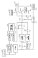
- a voltage of +5 V from the USB interface 1207 is supplied to the charging reference voltage generation circuit 1221 and the booster circuit 1231.
- the charging reference voltage generation circuit 1221 forms a voltage of 4.2 V as a charging reference voltage.
- the generated charging reference voltage is supplied to the buffer circuit 1222.
- the constant current charge / constant voltage charge switching determination circuit 1223 is supplied with the voltage of the all-solid-state battery 1203 via the switching circuit SW3 and the buffer circuit 1224.
- the battery voltage Vbat is taken out from the output of the buffer circuit 1224.
- the constant current charge / constant voltage charge switching determination circuit 1223 compares the charging reference voltage Vch and the battery voltage Vbat, and generates a switching control signal Vsw based on the comparison result.
- the switching circuits SW1 and SW2 are controlled by the switching control signal Vsw.
- Booster circuit 1231 boosts 5V to 8V, for example.
- the output voltage of the booster circuit 1231 is supplied to the constant current charging circuit 1232 and the constant voltage charging circuit 1233 via the switching circuit SW5.
- the switching circuit SW5 is controlled by the overcharge detection signal formed by the overcharge protection circuit 1235, and when the overcharge is detected, the switching circuit SW5 is turned off.
- the constant current charging circuit 1232 outputs a charging current for constant current charging.
- the charging current is supplied to the all solid state battery 1203 through the switching circuit SW1 and the switching circuit SW3.
- the constant voltage charging circuit 1233 outputs a charging voltage for constant voltage charging.
- the charging voltage is supplied to the all solid state battery 1203 through the switching circuits SW2 and SW3.
- the switching circuits SW1 and SW2 are controlled by a switching control signal Vsw formed by the constant current charging / constant voltage charging switching determination circuit 1223. For example, when the switching control signal Vsw is at a low level, the switching circuit SW1 is turned on, the switching circuit SW2 is turned off, and constant current charging is performed. When the switching control signal Vsw is at a high level, the switching circuit SW1 is turned off, the switching circuit SW2 is turned on, and constant voltage charging is performed.
- the switching circuit SW3 is controlled by the output (voltage of 8V) of the booster circuit 1231 via the gate circuit 1237.
- the switching circuit SW3 When 5V power is supplied through the USB interface 1207 and a voltage output of 8V is generated from the booster circuit 1231, the switching circuit SW3 is turned on.
- the switch circuit SW3 is turned on when charging and turned off when discharging.
- the gate circuit 1237 prohibits the control signal for turning on the switching circuit SW3 and turns off the switching circuit SW3.
- a load 1209 is connected to the all solid state battery 1203 via the switching circuit SW4.
- the switching circuit SW4 is controlled by the output of the overdischarge protection circuit 1236.
- the overdischarge protection circuit 1236 When the battery voltage of the all-solid-state battery 1203 becomes a predetermined voltage or less, the overdischarge protection circuit 1236 generates a control signal that determines that the battery is overdischarged and turns off the switching circuit SW4.
- the all-solid battery 1203 having a solid electrolyte unlike the existing lithium ion secondary battery, the battery does not deteriorate even if the battery voltage decreases.
- the battery voltage is equal to or lower than the cut-off voltage.
- the switching circuit SW4 is turned off and the battery power supply is cut off.
- the cut-off voltage is, for example, a voltage within a range of 2.0V to 3.3V.
- the switching circuit SW4 is turned off during charging and refresh discharge, but when the load 1209 is not connected, it is not necessary to turn off the switching circuit SW4.
- the refresh discharge circuit 1238 is connected to the all solid state battery 1203 through the switching circuit SW6.
- the switching circuit SW6 is turned on during refresh discharge. It is determined whether or not refresh discharge is executed at the start of charging of the all solid state battery 1203, and refresh discharge is executed based on the determination result. It should be noted that the start of charging means immediately before starting charging or immediately after starting charging.
- the refresh discharge is to discharge the all-solid-state battery 1203 until it becomes lower than the cut-off voltage during normal use.
- the refresh discharge discharges to a final voltage of 0V or less. More specifically, discharge is performed through a resistor, or discharge is performed by applying a reverse bias to discharge to a final voltage such as 0 V, ⁇ 0.5 V, or ⁇ 1.5 V.
- refresh discharge by the refresh discharge circuit 1238 is performed by connecting a resistor of (charge voltage ⁇ ItA) ⁇ or more and discharging for one hour or more.
- a refresh discharge control unit 1239 is provided to control the refresh discharge process, and the refresh discharge control unit 1239 determines whether or not to perform the refresh discharge. If it is determined that the refresh discharge is to be executed, the switching circuit SW3 is turned off via the gate circuit 1237 and the switching circuit SW6 is turned on.
- the refresh discharge controller 1239 is provided with a display device and a user interface that receives instructions from the user.
- the display device is a light emitting element such as an LED (Light Emitting Diode), and has a function of notifying the user that the refresh discharge operation is being performed.
- the display device may be configured as a touch panel, and may serve both as a display and a user interface.
- a button switch may be used as the user interface.
- the display device may display the charging operation state and the discharging operation state, respectively. Further, the user may be notified of the refresh discharge state by sound.
- the overdischarge protection circuit 1236, the overcharge protection circuit 1235, the refresh discharge circuit 1238, and the refresh discharge control unit 1239 are included in the battery protection IC 1205.
- FIG. 5 shows the flow of control operation by the refresh discharge controller 1239.
- Step ST1 For example, it is detected that a voltage of + 5V is supplied from the USB interface 1207, and an instruction to start charging is generated.
- Step ST2 It is determined whether or not the refresh discharge is arbitrarily started. The refresh discharge can be started by a user instruction from the user interface.
- Step ST4 When it is determined that the refresh discharge is arbitrarily started, the refresh discharge is performed. That is, the all solid state battery 1203 is discharged until the cut-off voltage during normal use (for example, +2 V) or less is reached. For example, the refresh discharge discharges to a final voltage of 0V or less.
- Step ST3 If the refresh discharge is not arbitrarily started, the deterioration of the all solid state battery 1203 is determined. For example, the number of charge / discharge cycles is counted, and when a predetermined number of cycles is reached, refresh discharge is performed. As another method for determining the deterioration, the battery is determined to be deteriorated when the increase amount of the internal resistance of the battery is equal to or greater than a predetermined value. Furthermore, the case where the degree of the temperature rise of a battery becomes high is determined as deterioration. Furthermore, when the SOC (State Of Charge) of the battery changes, it is determined that the battery has deteriorated. Step ST6: When it is determined in step ST3 that the battery has not deteriorated, normal charging is performed. For example, constant current and constant voltage charging is performed.
- SOC State Of Charge
- Step ST4 When it is determined in step ST3 that the battery has deteriorated, refresh discharge is performed.
- Step ST5 The display unit included in the refresh discharge control unit 1239 notifies the user that it is in the refresh discharge state.
- Step ST6 When the refresh discharge is completed, normal charging is performed. For example, constant current and constant voltage charging is performed.
- Step ST7 The charging operation ends.
- a mixture of TIMCAL KS6 mixed with an oxide glass electrolyte at a predetermined weight ratio, mixed with an acrylic binder and (lithium cobaltate + oxide glass electrolyte): acrylic binder 70: 30, Mix in butyl acetate to a solid content of 30 wt% and stir overnight with 5 mm ⁇ zirconia balls. It is coated on a release film and dried at 80 ° C. for 10 minutes.
- the above products 1 to 3 are laminated on the SUS304 substrate by peeling off the release film in the order of 1, 3, and 2 and thermocompression bonded at 100 ° C. for 10 minutes. 5). 4, after removing the acrylic binder by heating at 300 ° C. for 10 hours, another SUS304 substrate is placed on the film and sintered at 400 ° C. for 30 minutes. 6).
- the battery produced in 5 was placed in a 2016 size coin cell case and sealed with a caulking machine to produce an all-solid battery of the present technology. This all solid state battery had a capacity of 0.225 mAh in terms of the weight of the charged positive electrode active material.
- the full charge voltage is set to 4.2V, and the cut-off voltage during normal use is set to 3.0V.
- ⁇ Normal cycle> The all-solid-state battery manufactured as described above is subjected to CC (constant current) charging to 4.2 V with a current of 0.2 C in terms of positive electrode capacity using a charging / discharging device, and to a current of 0.01 C at 4.2 V.
- CV (constant voltage) charging is performed.
- CC discharge was performed to 3.0 V with a current of 0.2 C.
- charging / discharging was repeated up to 20 cycles.
- ⁇ Refresh discharge> The all-solid-state battery was CC-discharged to 0 V at a current of 0.2 C as a refresh discharge, and CV-discharged to a current of 0.01 C at 0 V.
- Example 2 An all-solid battery was prepared in the same manner as in Example 1, and 20 cycles of charge / discharge were performed in a normal cycle. A resistance of (4.2 V ⁇ 1 ItA (0.000225 A)) ⁇ 18 k ⁇ was connected as a refresh discharge to this all solid state battery, and discharge was performed for 10 hours. This all-solid-state battery was charged and discharged for one cycle using a normal cycle recipe, and capacity recovery after refresh discharge was confirmed.
- Example 3 An all-solid battery was produced in the same manner as in Example 1, and the charge / discharge cycle was repeated until the capacity retention rate with respect to the initial discharge capacity reached 95% (reached at the 55th cycle). As a refresh discharge, the all-solid battery was subjected to CC discharge to 0 V with a current of 0.2 C, and CV discharge to 0 C with a current of 0.2 C. This all-solid-state battery was charged and discharged for one cycle using a normal cycle recipe, and capacity recovery after refresh discharge was confirmed.
- Example 4 An all-solid battery was prepared in the same manner as in Example 1, and 20 cycles of charge / discharge were performed in a normal cycle. As a refresh discharge, CC discharge was performed at a current of 0.2 C to ⁇ 0.5 V, and CV discharge was performed at ⁇ 0.5 V to a current of 0.01 C. This all-solid-state battery was charged and discharged for one cycle using a normal cycle recipe, and capacity recovery after refresh discharge was confirmed.
- Example 1 An all-solid battery was prepared in the same manner as in Example 1, and 20 cycles of charge / discharge were performed in a normal cycle. This all-solid battery was not subjected to refresh discharge, and was charged and discharged for one cycle as it was using a normal cycle recipe.
- Example 2 An all-solid battery was prepared in the same manner as in Example 1, and 20 cycles of charge / discharge were performed in a normal cycle. This all-solid-state battery was subjected to CC discharge to 2.5 V at a current of 0.2 C as a refresh discharge, and CV discharge to a current of 2.5 V and 0.01 C. This all-solid-state battery was charged and discharged for one cycle using a normal cycle recipe, and capacity recovery after refresh discharge was confirmed. Table 1 shows a comparison of the discharge capacities of the above charge / discharge tests.
- FIG. 6 shows measurement results of changes in battery capacity.
- the change in capacity as a result of performing a refresh discharge every 20 charge / discharge cycles is shown for two types of all solid state batteries. From this measurement result, it can be seen that the decrease in capacity is recovered by the present technology.
- FIG. 7 shows an example of a universal credit card 1301. It has almost the same size as a normal credit card and has an IC chip and a battery built therein. Further, a display 1302 that consumes less power and an operation unit such as direction keys 1303a and 1303b are provided. Further, a charging terminal 1304 is provided on the surface of the universal credit card 1301.
- the user can specify a credit card loaded in advance on the universal credit card 1301 by operating the direction keys 1303a and 1303b while looking at the display 1302.
- a plurality of credit cards are loaded in advance
- information indicating each credit card is displayed on the display 1302
- the user can designate a desired credit card by operating the direction keys 1303a and 1303b.
- the charging / discharging device according to the present technology can be applied when an all-solid battery is used as a battery built in the universal credit card 1301. Note that the above is an example, and it goes without saying that the charge / discharge device according to the present technology can be applied to any electronic card other than the universal credit card 1301.
- a wireless terminal in a wireless sensor network is referred to as a sensor node, and includes one or more wireless chips, a microprocessor, a power supply (battery), and the like.
- the sensor network it is used to monitor energy saving management, health management, industrial measurement, traffic conditions, farm work, and the like.
- As the type of sensor voltage, temperature, gas, illuminance, and the like are used.
- a power monitor node In the case of energy saving management, a power monitor node, a temperature / humidity node, an illuminance node, a CO 2 node, a human sensor node, a remote control node, a router (relay machine), and the like are used as sensor nodes. These sensor nodes are provided so as to constitute a wireless network in homes, office buildings, factories, stores, amusement facilities, and the like.
- ZigBee (registered trademark) can be used as one of the wireless interfaces of the sensor network.
- This wireless interface is one of the short-range wireless communication standards, and has a feature that it is inexpensive and consumes less power, instead of having a short transferable distance and a low transfer speed. Therefore, it is suitable for mounting on a battery-driven device.
- the basic part of this communication standard is standardized as IEEE 802.15.4.
- the ZigBee (Registered Trademark) Alliance has formulated specifications for communication protocols between devices above the logical layer.
- FIG. 8 shows an exemplary configuration of the wireless sensor node 1401.
- a detection signal of the sensor 1402 is supplied to an AD conversion circuit 1404 of a microprocessor (MPU) 1403.
- MPU microprocessor
- the various sensors described above can be used as the sensor 1402.
- a memory 1406 is provided in association with the microprocessor 1403.
- the output of the battery 1407 is supplied to the power supply control unit 1408, and the power supply of the sensor node 1401 is managed.
- the battery 1407 the above-described all-solid battery, card-type battery pack, or the like can be used.
- the charge / discharge device according to the present technology is applied when an all-solid battery is used.
- the program is installed in the microprocessor 1403.
- the microprocessor 1403 processes the detection result data of the sensor 1402 output from the AD conversion circuit 1404 according to the program.
- a wireless communication unit 1409 is connected to the communication control unit 1406 of the microprocessor 1403, and detection result data is transmitted from the wireless communication unit 1409 to a network terminal (not shown) using, for example, ZigBee (registered trademark). Connected to the network via a network terminal.
- a predetermined number of wireless sensor nodes can be connected to one network terminal.
- the network type may be a tree type, a mesh type, a linear type, or the like.
- a wearable terminal is a wristband type electronic device.
- the wristband type activity meter is also called a smart band, and it is possible to obtain data on human activities such as the number of steps, distance traveled, calories burned, sleep amount, heart rate, etc. just by wrapping around the wrist. It can be done.
- the acquired data can also be managed with a smartphone.
- a mail transmission / reception function can also be provided. For example, a mail notification function that notifies a user of an incoming mail by an LED (Light Emitting Diode) lamp and / or vibration is used.
- LED Light Emitting Diode
- FIG. 9 and 10 show an example of a wristband type activity meter that measures, for example, a pulse.
- FIG. 9 shows an example of the external configuration of the wristband type activity meter 1501.
- FIG. 10 shows a configuration example of the main body 1502 of the wristband type activity meter 1501.
- the wristband type activity meter 1501 is a wristband type measuring device that measures, for example, a pulse of a subject by an optical method.
- the wristband type active mass meter 1501 includes a main body 1502 and a band 1503, and the band 1503 is attached to the arm (wrist) 1504 of the subject like a wristwatch.
- the main-body part 1502 irradiates the measurement light of a predetermined wavelength to the part containing the pulse of a test subject's arm 1504, and measures a test subject's pulse based on the intensity
- the main body 1502 is configured to include a substrate 1521, an LED 1522, a light receiving IC (Integrated Circuit) 1523, a light shield 1524, an operation unit 1525, an arithmetic processing unit 1526, a display unit 1527, and a wireless device 1528.
- the LED 1522, the light receiving IC 1523, and the light shield 1524 are provided over the substrate 1521.
- the LED 1522 irradiates a portion including the pulse of the arm 1504 of the subject under measurement light of a predetermined wavelength under the control of the light receiving IC 1523.
- the light receiving IC 1523 receives light that has returned after the measurement light is applied to the arm 1504.
- the light receiving IC 1523 generates a digital measurement signal indicating the intensity of the returned light, and supplies the generated measurement signal to the arithmetic processing unit 1526.
- the light shield 1524 is provided between the LED 1522 and the light receiving IC 1523 on the substrate 1521.
- the light shield 1524 prevents measurement light from the LED 1522 from directly entering the light receiving IC 1523.
- the operation unit 1525 is composed of various operation members such as buttons and switches, and is provided on the surface of the main body 1502 or the like.
- the operation unit 1525 is used to operate the wristband type activity meter 1501 and supplies a signal indicating the operation content to the arithmetic processing unit 1526.
- the arithmetic processing unit 1526 performs arithmetic processing for measuring the pulse of the subject based on the measurement signal supplied from the light receiving IC 1523.
- the arithmetic processing unit 1526 supplies the pulse measurement result to the display unit 1527 and the wireless device 1528.
- the display unit 1527 is configured by a display device such as an LCD (Liquid Crystal Display), and is provided on the surface of the main body unit 1502.
- the display unit 1527 displays the measurement result of the subject's pulse and the like.
- the wireless device 1528 transmits the measurement result of the subject's pulse to an external device by wireless communication of a predetermined method. For example, as illustrated in FIG. 10, the wireless device 1528 transmits the measurement result of the subject's pulse to the smartphone 1505 and causes the screen 1506 of the smartphone 1505 to display the measurement result. Furthermore, the measurement result data is managed by the smartphone 1505, and the measurement result can be browsed by the smartphone 1505 or stored in a server on the network. Note that any method can be adopted as a communication method of the wireless device 1528.
- the light receiving IC 1523 can also be used when measuring a pulse in a part other than the subject's arm 1504 (eg, finger, earlobe, etc.).
- the wristband type active mass meter 1501 described above can accurately measure the pulse wave and pulse of the subject by removing the influence of body movement by the signal processing in the light receiving IC 1523. For example, even if the subject performs intense exercise such as running, the pulse wave and pulse of the subject can be accurately measured. In addition, for example, even when the subject wears the wristband type activity meter 1501 for a long time and performs measurement, the influence of the subject's body movement can be removed and the pulse wave and the pulse can be accurately measured. .
- the power consumption of the wristband type activity meter 1501 can be reduced by reducing the amount of calculation. As a result, for example, it is possible to perform measurement by wearing the wristband type activity meter 1501 on the subject for a long time without performing charging or battery replacement.
- the wristband type activity meter 1501 includes an electronic circuit of the main body and a battery pack.
- the battery pack is detachable by the user.
- the electronic circuit is a circuit included in the main body 1502 described above. The present technology can be applied when using an all-solid battery as a battery.
- FIG. 11 and 12 show an example of a wristband type electronic device.
- FIG. 11 shows an example of the external configuration of the wristband type electronic device 1601.
- FIG. 12 illustrates a configuration example of a wristband type electronic device 1601 (hereinafter simply referred to as “electronic device 1601”).
- the electronic device 1601 is, for example, a watch-type so-called wearable device that is detachable from the human body.
- the electronic device 1601 includes, for example, a band portion 1611 attached to the arm, a display device 1612 that displays numbers, characters, symbols, and the like, and operation buttons 1613.
- the band portion 1611 is formed with a plurality of hole portions 1611a and protrusions 1611b formed on the inner peripheral surface (the surface that comes into contact with the arm when the electronic device 1601 is attached).
- the electronic device 1601 In the use state, the electronic device 1601 is bent so that the band portion 1611 is substantially circular as shown in FIG. 11, and the protrusion 1611b is inserted into the hole portion 1611a and attached to the arm. By adjusting the position of the hole 1611a into which the protrusion 1611b is inserted, the diameter can be adjusted corresponding to the thickness of the arm.
- the protrusion 1611b is removed from the hole 1611a, and the band 1611 is stored in a substantially flat state.
- the sensor according to the embodiment of the present technology is provided over the entire band portion 1611.
- FIG. 12 is a block diagram illustrating a configuration example of the electronic device 1601.
- the electronic device 1601 includes a sensor 1620 including a controller IC 1615 as a drive control unit and a host device 1616 in addition to the display device 1612 described above.
- the sensor 1620 may include a controller IC 1615.
- the sensor 1620 can detect both pressing and bending.
- the sensor 1620 detects a change in capacitance according to the pressing, and outputs an output signal corresponding to the change to the controller IC 1615. Further, the sensor 1620 detects a change in resistance value (resistance change) according to bending, and outputs an output signal corresponding to the change to the controller IC 1615.
- the host device 1616 executes various processes based on information supplied from the controller IC 1615. For example, processing such as displaying character information and image information on the display device 1612, moving the cursor displayed on the display device 1612, scrolling the screen, and the like is executed.
- the display device 1612 is a flexible display device, for example, and displays a video (screen) based on a video signal or a control signal supplied from the host device 1616.
- Examples of the display device 1612 include a liquid crystal display, an electroluminescence (EL) display, and electronic paper, but are not limited thereto.
- the electronic device 1601 includes a main body electronic circuit and a battery pack.
- the battery pack is detachable by the user.
- the present technology can be applied to a case where an all-solid battery is used as the battery.
- Smart watch as an application Hereinafter, application examples in which the present technology is applied to a smart watch will be described.
- Smart watches have the same or similar appearance as existing wristwatch designs, and are worn on the user's wrist in the same way as wristwatches.
- Information displayed on the display is used to receive incoming calls and e-mails.
- a function for notifying the user of various messages such as.
- smart watches having functions such as an electronic money function and an activity meter have been proposed.
- a display is incorporated on the surface of the main body portion of the electronic device, and various information is displayed on the display.
- the smart watch can also cooperate with functions, contents, and the like of the communication terminal by performing short-range wireless communication such as Bluetooth (registered trademark) with a communication terminal (smart phone or the like).
- a plurality of segments connected in a band, a plurality of electronic components arranged in the plurality of segments, and a plurality of electronic components in the plurality of segments are connected to each other in at least one segment.
- a device including a flexible circuit board arranged in a meandering shape has been proposed. By having such a meandering shape, the flexible circuit board is not stressed even when the band is bent, and the circuit is prevented from being cut.
- a portion corresponding to a band of a normal wristwatch is a main body, and the band (belt) alone is formed as an electronic device. That is, a conventional watch can be used as it is for the watch body that displays the time with a hand or the like.
- a band-type electronic device attached to the watch body incorporates a communication function and a notification function.
- the smart watch of this example can perform notifications such as e-mails and incoming calls, log recording of user behavior history, telephone calls, and the like.
- the smart watch has a function as a non-contact type IC card and can perform settlement and authentication using the non-contact type IC card.
- the smart watch of this application example has built-in circuit components that perform communication processing and notification processing in a metal band.
- the band is configured by connecting a plurality of segments, and a circuit board, a vibration motor, a battery, and an acceleration sensor are accommodated in each segment.
- Components such as circuit boards, vibration motors, batteries, and acceleration sensors of each segment are connected by a flexible printed circuit board (hereinafter referred to as “FPC”).
- FPC flexible printed circuit board
- the FPC meanders.
- the meandering shape may be any shape such as an S shape, a V shape, a U shape, a Z shape, a curved shape, a semicircular shape, a polygonal line shape, and the like. By doing so, even if a metal band is bent, the meandering shape of the FPC only extends and the FPC does not break. Furthermore, the entrance / exit of the FPC in the segment part is pressed with rubber packing (relatively soft resin). The mating portion keeps the waterproofness of each segment by allowing the FPC to move freely without pressing the doorway. By introducing this “pairing part”, it is possible to prevent the FPC from being cut while ensuring the waterproofness of the main body. In the case where an electronic component is completed with only one component (segment), this “pairing portion” can be omitted.
- an antenna for Bluetooth registered trademark
- an antenna for NFC Near Field Communication
- an insulator is sandwiched between the adjacent parts.
- a component with a built-in antenna uses the entire surface (approximately six surfaces) of the component as an antenna, but the antenna characteristics deteriorate when it comes into contact with the user's skin, so the surface that contacts the user's skin is not used as an antenna.
- a material other than metal may be used.
- an insulating layer may be sandwiched between a metal part that touches the user's skin and a part that functions as an antenna.
- a component with a built-in antenna may be provided with a slit and used as a slit antenna.
- a part for arranging the antenna for Bluetooth (registered trademark) and a part for arranging the antenna for NFC may be different parts.
- Bluetooth (registered trademark) wireless communication uses the 2.4 GHz band, when wireless communication is performed between a smart watch and a smartphone with no obstacles, pairing up to an average of about 10 m is possible. It was.
- the antenna problem can be solved by introducing a technique using the metal casing itself as an antenna.
- FIG. 13 shows the overall configuration of the smart watch.
- the band-type electronic device 2000 is a metal band attached to the watch main body 3000 and is attached to the user's arm.
- the watch body 3000 includes a dial 3100 for displaying time.
- the watch body 3000 may display the time electronically on a liquid crystal display or the like instead of the dial 3100.
- the band-type electronic device 2000 has a configuration in which a plurality of segments 2110 to 2230 are connected.
- the segment 2110 is attached to one band attachment hole of the watch body 3000, and the segment 2230 is attached to the other band attachment hole of the watch body 3000.
- each of the segments 2110 to 2230 is made of metal.
- FIG. 13 and 14 show a state in which the watch main body 3000 and the segment 2230 are separated in order to explain the configuration of the band-type electronic device 2000, but the segment 2230 is attached to the watch main body 3000 in actual use. It is done.
- the band-type electronic device 2000 can be worn on the user's arm in the same manner as a normal wristwatch.
- the connection location of each segment 2110 to 2230 can be moved. Since the connection part of the segment is movable, the band-type electronic device 2000 can be fitted to the user's arm.
- a buckle portion 2300 is disposed between the segment 2170 and the segment 2160.
- the buckle portion 2300 extends long when unlocked and shortens when locked.
- Each segment 2110 to 2230 has a plurality of sizes. For example, the segment 2170 connected to the buckle portion 2300 is the largest size.
- FIG. 15 shows a part of the internal configuration of the band-type electronic apparatus 2000.
- the inside of three segments 2170, 2180, 2190, 2200, and 2210 is shown.
- a flexible circuit board 2400 is arranged inside five continuous segments 2170 to 2210.
- Various electronic components are arranged in the segment 2170, batteries 2411 and 2421 are arranged in the segments 2190 and 2210, and these components are electrically connected by the flexible circuit board 2400.
- a segment 2180 between the segment 2170 and the segment 2190 has a relatively small size, and the flexible circuit board 2400 in a meandering state is disposed.
- the flexible circuit board 2400 is disposed in a state of being sandwiched between waterproofing members.
- the inside of the segments 2170 to 2210 has a waterproof structure. The waterproof structure of the segments 2170 to 2210 will be described later.
- FIG. 16 is a block diagram showing a circuit configuration of the band-type electronic apparatus 2000.
- the circuit inside the band-type electronic device 2000 has a configuration independent of the watch main body 3000.
- the watch main body 3000 includes a movement unit 3200 that rotates hands arranged on the dial 3100.
- a battery 3300 is connected to the movement unit 3200.
- the movement unit 3200 and the battery 3300 are built in the casing of the watch main body 3000.
- a data processing unit 4101 In the segment 2170, a data processing unit 4101, a wireless communication unit 4102, an NFC communication unit 4104, and a GPS unit 4106 are arranged.
- Antennas 4103, 4105, and 4107 are connected to the wireless communication unit 4102, the NFC communication unit 4104, and the GPS unit 4106, respectively.
- Each antenna 4103, 4105, 4107 is arranged in the vicinity of a slit 2173 described later of the segment 2170.
- the wireless communication unit 4102 performs short-range wireless communication with other terminals based on, for example, Bluetooth (registered trademark) standards.
- the NFC communication unit 4104 performs wireless communication with a nearby reader / writer according to the NFC standard.
- the GPS unit 4106 is a positioning unit that receives radio waves from a satellite of a system called GPS (Global Positioning System) and measures the current position. Data obtained by the wireless communication unit 4102, the NFC communication unit 4104, and the GPS unit 4106 is supplied to the data processing unit 4101.
- GPS Global Positioning System
- a display 4108 In the segment 2170, a display 4108, a vibrator 4109, a motion sensor 4110, and an audio processing unit 4111 are arranged.
- the display 4108 and the vibrator 4109 function as a notification unit that notifies the wearer of the band-type electronic device 2000.
- the display 4108 includes a plurality of light emitting diodes, and notifies the user by lighting or blinking of the light emitting diodes.
- the plurality of light emitting diodes are disposed, for example, in a slit 2173 described later of the segment 2170, and notification of incoming calls or reception of e-mails is made by lighting or blinking.
- the display 4108 may be a type that displays characters, numbers, and the like.
- Vibrator 4109 is a member that vibrates segment 2170.
- the band-type electronic device 2000 notifies the incoming call or the reception of an e-mail by the vibration of the segment 2170 by the vibrator 4109.
- the motion sensor 4110 detects the movement of the user wearing the band-type electronic device 2000.
- an acceleration sensor As the motion sensor 4110, an acceleration sensor, a gyro sensor, an electronic compass, an atmospheric pressure sensor, or the like is used.
- the segment 2170 may incorporate a sensor other than the motion sensor 4110.
- a biosensor that detects the pulse of the user wearing the band-type electronic device 2000 may be incorporated.
- a microphone 4112 and a speaker 4113 are connected to the audio processing unit 4111, and the audio processing unit 4111 performs a call process with the other party connected by wireless communication in the wireless communication unit 4102.
- the voice processing unit 4111 can also perform processing for voice input operation.
- a battery 2411 is built in, and in the segment 2210, a battery 2421 is built.
- the batteries 2411 and 2421 are configured by, for example, all solid state batteries, and supply driving power to the circuits in the segment 2170.
- the circuit in the segment 2170 and the batteries 2411 and 2421 are connected by a flexible circuit board 2400 (FIG. 15).
- the segment 2170 includes terminals for charging the batteries 2411 and 2421.
- electronic components other than the batteries 2411 and 2421 may be arranged in the segments 2190 and 2210.
- the segments 2190 and 2210 may include a circuit that controls charging and discharging of the batteries 2411 and 2421.
- FIG. 15 shows a configuration of segments 2170 to 2210 in which electronic components and the like are arranged, and a buckle portion 2300 connected to the segment 2170.
- the segments 2170 to 2210 are shown with a lid member (not shown) opened.
- the casing constituting each of the segments 2170 to 2210 is formed of a metal such as stainless steel.
- FIG. 15 shows a state where the first member 2310 and the second member 2320 of the buckle portion 2300 are opened.
- Buckle portion 2300 is arranged at a position overlapping the back surface (upper side in FIG. 15) of segment 2170 when first member 2310 and second member 2320 are closed.
- the segment 2170 has a larger size than the other segments, and each electronic component shown in FIG. 16 is accommodated.
- An internal housing 2500 made of a transparent resin (or translucent resin) is disposed inside the segment 2170, and a flexible circuit board 2401 and the like are disposed in the internal housing 2500.
- One connecting portion 2171 of the segment 2170 is connected to the connecting portion 2330 of the buckle portion 2300.
- the other connecting portion 2172 of the segment 2170 is connected to the connecting portion 2183 of the segment 2180.
- a connecting portion 2184 of the segment 2180 is connected to the segment 2190.
- a segment 2200 is connected next to the segment 2190, and a segment 2210 is connected next to the segment 2200.
- two segments are connected using a connection pin (not shown).
- a slit 2173 is formed on the surface of the segment 2170.
- a plurality of light emitting diodes constituting the display 4108 is disposed in the inner casing 2500 made of a transparent or translucent resin in the vicinity of the slit 2173. Therefore, the user can confirm light emission or blinking of the light emitting diode through the slit 2173 of the segment 2170. By such light emission and blinking of the light emitting diodes, various states such as incoming calls and reception of e-mails are notified.
- the antennas 4103, 4105, and 4107 are arranged in the internal housing 2500 close to the slit 2173. Therefore, the antennas 4103, 4105, and 4107 can maintain a good communication state with the outside of the metal segment 2170.
- the first portion 2401 of the flexible circuit board 2400 is disposed in the internal housing 2500 of the segment 2170.
- the first portion 2401 of the flexible circuit board 2400 is connected to the rigid board 2440 through the connection member 2431.
- Various electronic components 2441, 2442, 2443,... Are connected to the rigid board 2440.
- the electronic components 2441, 2442, 2443,... Correspond to the processing units 4101 to 4113 shown in FIG.
- Segment 2190 and segment 2210 are sized to accommodate batteries 2411 and 2421. Segment 2180 and segment 2200 are smaller in size than segments 2190 and 2210.
- the second portion 2402 of the flexible circuit board 2400 is disposed in a meandering state on the segment 2180.
- a battery 2411 is connected to the third portion 2403 of the flexible circuit board 2400.
- the fourth portion 2404 of the flexible circuit board 2400 is disposed in a meandering state on the segment 2200.
- a battery 2421 is connected to the fifth portion 2405 of the flexible circuit board 2400. Details of the meandering state of the flexible circuit board 2400 will be described with reference to FIG.
- FIG. 17 is a cross-sectional view showing a state where the flexible circuit board 2400 is disposed inside the segments 2170 to 2190.
- the flexible circuit board 2400 is continuously arranged in each of the segments 2170 to 2190.
- the flexible circuit board 2400 passes through the inside of the connecting portion 2171 of the segment 2170 and the connecting portion 2183 of the segment 2180.
- a waterproof member 2174 is disposed inside the connecting portion 2171 at a location where the flexible circuit board 2400 passes, and water intrusion into the segment 2170 is prevented.
- a waterproof member 2175 is also disposed in the internal housing 2500 of the segment 2170.
- waterproof members 2181 and 2182 are arranged inside the segment 2180, and water intrusion into the segment 2180 is prevented.
- Each waterproof member 2174, 2175, 2181, 2182 is formed of a relatively soft resin, for example, and the gap between the inside of the segment 2180 and the flexible circuit board 2400 is closed.
- the flexible circuit board 2400 is arranged in a meandering state. That is, a curved meandering portion 2400X is formed on the flexible circuit board 2400 inside the segment 2180.
- the meandering portion 2400X of the flexible circuit board 2400 functions to prevent damage to the flexible circuit board 2400. For example, even when the connecting portion between the segment 2180 and the segment 2170 is bent greatly, the meandering portion 2400 ⁇ of the flexible circuit board 2400 extends linearly and the flexible circuit board 2400 is not pulled. Therefore, the trouble that the circuit pattern in the flexible circuit board 2400 breaks does not occur.
- the meandering portion 2400X shown in FIG. 17 is an example, and other shapes may be used. That is, the meandering portion 2400X can have various meandering shapes such as an S shape, a V shape, a U shape, a Z shape, a curved shape, a semicircular shape, and a polygonal line shape.
- the present technology can be applied when an all solid state battery is used as the battery 2411 described above.
- FIG. 18 shows a state where the battery 2411 is arranged in the segment 2190.
- the configuration in which the battery 2421 is arranged in the segment 2210 is the same.
- a battery 2411 is arranged at a battery arrangement location 2191 inside the segment 2190.
- the adhesive sheet 2703 is arranged between the battery arrangement location 2191 and the battery 2411.
- the third portion 2403 of the flexible circuit board 2400 is bonded to the surface of the battery 2411 (upper side in FIG. 18) with an adhesive sheet 2701.
- the adhesive sheet 2701 By adhesion using the adhesive sheet 2701, the electrodes 2411A and 2411B on the surface of the battery 2411 are connected to the circuit pattern in the flexible circuit board 2400.
- the surface of the battery 2411 is bonded to a lid (not shown) of the segment 2190 via the adhesive sheet 2702.
- the adhesive sheet 2701 is configured to block the periphery of the surface of the battery 2411. Therefore, the adhesive sheet 2701 functions as a waterproof member for the battery 2411 in the segment 2190.
- the battery may be disposed in another segment of the band type electronic device 2000.
- the above-mentioned smart watch can perform notifications such as incoming e-mails and telephone calls, log recording of user activity history, telephone calls, and the like.
- the smart watch has a function as a non-contact type IC card and can perform settlement and authentication using the non-contact type IC card.
- the smart watch of this example can use the same watch body as that of a conventional watch, it can be a wristwatch with excellent design.
- the plurality of segments have a waterproof structure, and the flexible circuit board is meanderingly arranged, so that the circuit pattern does not cut.
- the antenna in the metal segment 2170 is arranged in the vicinity of the slit of the segment 2170, transmission and reception can be performed satisfactorily.
- Glasses type terminal as an application example
- a head-mounted display glasses-type terminal as a kind of head-mounted display (HMD)
- the glasses-type terminal described below can display information such as text, symbols, and images superimposed on the scenery in front of you. That is, a light-weight and thin image display device display module dedicated to a transmissive glasses-type terminal is mounted.
- This image display device comprises an optical engine and a hologram light guide plate.
- the optical engine emits image light such as an image and text using a micro display lens. This image light is incident on the hologram light guide plate.
- a hologram light guide plate has hologram optical elements incorporated at both ends of a transparent plate, and propagates image light from an optical engine through a very thin transparent plate having a thickness of 1 mm to the eyes of an observer. deliver. With such a configuration, a lens having a transmittance of, for example, 85% and a thickness of 3 mm (including protective plates before and after the light guide plate) is realized. With such a glasses-type terminal, it is possible to see the results of players and teams in real time while watching sports, and to display a tourist guide at a destination.
- the image display unit has a glasses-type configuration as shown in FIG. That is, as with normal glasses, the frame 5003 for holding the right image display unit 5001 and the left image display unit 5002 is provided in front of the eyes.
- the frame 5003 includes a front portion 5004 disposed in front of the observer, and two temple portions 5005 and 5006 that are rotatably attached to both ends of the front portion 5004 via hinges.
- the frame 5003 is made of the same material as that of normal glasses, such as metal, alloy, plastic, or a combination thereof.
- a headphone unit may be provided.
- the right image display unit 5001 and the left image display unit 5002 are arranged so as to be positioned in front of the user's right eye and in front of the left eye, respectively.
- Temple units 5005 and 5006 hold the image display units 5001 and 5002 on the user's head.
- a right display driving unit 5007 is disposed inside the temple unit 5005 at a connection portion between the front unit 5004 and the temple unit 5005.
- a left display driving unit 5008 is arranged inside the temple unit 5006 at a connection portion between the front unit 5004 and the temple unit 5006.
- the frame 5003 includes a battery, an acceleration sensor, a gyro, an electronic compass, a microphone / speaker, and the like.
- the present technology can be applied when using an all-solid battery as a battery.
- an image pickup apparatus is attached, and still images / moving images can be taken.
- a controller connected to the glasses unit via, for example, a wireless or wired interface is provided.
- the controller is provided with a touch sensor, various buttons, a speaker, a microphone, and the like.
- it has a linkage function with a smartphone. For example, it is possible to provide information according to the user's situation by utilizing the GPS function of a smartphone.
- the image display device the right image display unit 5001 or the left image display unit 5002 will be mainly described.
- FIG. 20 shows a conceptual diagram of a first example of an image display device (right image display unit 5001 or left image display unit 5002) of a glasses-type terminal.
- the image display device in the eyeglass-type terminal of the first example includes the first configuration of the image generation device and the first configuration of the optical device.
- the image display device 5100 receives the light emitted from the image generation device 5110 configured from the image generation device having the first configuration and the image generation device 5110, is guided, and is emitted toward the pupil 5041 of the observer.
- the optical device 5120 is attached to the image generation device 5110.
- the optical device 5120 includes the optical device having the first configuration, and the light incident from the image generation device 5110 propagates through the interior by total reflection, and then is emitted toward the observer's pupil 5041.
- the first light deflecting unit 5130 that deflects the light incident on the light guide plate 5121 and the light guide plate 5121 are propagated by total reflection so that the light incident on the light guide plate 5121 is totally reflected inside the light guide plate 5121.
- second deflection means 5140 is provided that deflects the light propagated through the light guide plate 5121 by total reflection over a plurality of times.
- the first deflecting unit 5130 and the second deflecting unit 5140 are disposed inside the light guide plate 5121.
- the first deflecting unit 5130 reflects the light incident on the light guide plate 5121
- the second deflecting unit 5140 transmits the light propagating through the light guide plate 5121 by total reflection, and transmits and reflects the light.
- the first deflecting unit 5130 functions as a reflecting mirror
- the second deflecting unit 5140 functions as a semi-transmissive mirror.
- the first deflecting means 5130 provided inside the light guide plate 5121 is made of aluminum, and is composed of a light reflecting film (a kind of mirror) that reflects light incident on the light guide plate 5121. .
- the second deflecting means 5140 provided inside the light guide plate 5121 is composed of a multilayer laminated structure in which a large number of dielectric laminated films are laminated.
- the dielectric laminated film is composed of, for example, a TiO 2 film as a high dielectric constant material and an SiO 2 film as a low dielectric constant material.
- a six-layer dielectric laminated film is shown, but the present invention is not limited to this.
- a thin piece made of the same material as that constituting the light guide plate 5121 is sandwiched between the dielectric laminated film and the dielectric laminated film.
- the parallel light incident on the light guide plate 5121 is reflected (or diffracted) so that the parallel light incident on the light guide plate 5121 is totally reflected inside the light guide plate 5121.
- the parallel light propagated through the light guide plate 5121 by total reflection is reflected (or diffracted) a plurality of times and is emitted from the light guide plate 5121 in the state of parallel light.
- the first deflecting unit 5130 cuts out a portion 5124 of the light guide plate 5121 where the first deflecting unit 5130 is provided, thereby providing the light guide plate 5121 with an inclined surface on which the first deflecting unit 5130 is to be formed, and vacuuming the light reflecting film on the inclined surface. After vapor deposition, the cut-out portion 5124 of the light guide plate 5121 may be bonded to the first deflecting means 5130.
- the second deflecting unit 5140 is formed by laminating a large number of the same material (for example, glass) as the material constituting the light guide plate 5121 and a dielectric laminated film (for example, it can be formed by a vacuum deposition method).
- a multilayer laminated structure is manufactured, and a portion 5125 provided with the second deflecting means 5140 of the light guide plate 5121 is cut out to form a slope, and the multilayer laminated structure is bonded to the slope and polished to adjust the outer shape. That's fine. In this way, an optical device 5120 in which the first deflection unit 5130 and the second deflection unit 5140 are provided inside the light guide plate 5121 can be obtained.
- the light guide plate 5121 made of optical glass or plastic material has two parallel surfaces (a first surface 5122 and a second surface 5123) extending in parallel with the axis of the light guide plate 5121.
- the first surface 5122 and the second surface 5123 are opposed to each other. Then, parallel light enters from the first surface 5122 corresponding to the light incident surface, propagates through the interior by total reflection, and then exits from the first surface 5122 corresponding to the light exit surface.
- the image generation device 5110 includes the first configuration image generation device, the image formation device 5111 having a plurality of pixels arranged in a two-dimensional matrix, and the pixels of the image formation device 5111.
- a collimating optical system 5112 for emitting light as parallel light is provided.
- the image forming apparatus 5111 includes a reflective spatial light modulator 5150 and a light source 5153 including a light emitting diode that emits white light. More specifically, the reflective spatial light modulator 5150 reflects a part of light from a liquid crystal display (LCD) 5151 composed of LCOS (Liquid Crystal On On Silicon) as a light valve and a light source 5153.
- the polarizing beam splitter 5152 is guided to the liquid crystal display device 5151, and part of the light reflected by the liquid crystal display device 5151 is transmitted to the collimating optical system 5112.
- the LCD is not limited to the LCOS type.
- the liquid crystal display device 5151 includes a plurality of (for example, 320 ⁇ 240) pixels arranged in a two-dimensional matrix.
- the polarization beam splitter 5152 has a known configuration and structure. Non-polarized light emitted from the light source 5153 collides with the polarization beam splitter 5152. In the polarization beam splitter 5152, the P-polarized component passes and is emitted out of the system. On the other hand, the S-polarized component is reflected by the polarization beam splitter 5152, enters the liquid crystal display device 5151, is reflected inside the liquid crystal display device 5151, and is emitted from the liquid crystal display device 5151.
- the light emitted from the liquid crystal display device 5151 contains a lot of P-polarized light components, and the light emitted from the pixel displaying “black” is S-polarized light. Contains many ingredients. Therefore, among the light emitted from the liquid crystal display device 5151 and colliding with the polarization beam splitter 5152, the P-polarized component passes through the polarization beam splitter 5152 and is guided to the collimating optical system 5112.
- the liquid crystal display device 5151 includes, for example, a plurality of (for example, 320 ⁇ 240) pixels (the number of liquid crystal cells is three times the number of pixels) arranged in a two-dimensional matrix.
- the collimating optical system 112 is composed of, for example, a convex lens, and in order to generate parallel light, the image forming apparatus 5111 (more specifically, the liquid crystal display device 5151) is located at the focal position (position) in the collimating optical system 5112. Is arranged.
- One pixel is composed of a red light emitting subpixel that emits red, a green light emitting subpixel that emits green, and a blue light emitting subpixel that emits blue.
- the image display device is incident and guided by the light emitted from the image generation device and the image generation device, toward the observer's pupil. It is comprised from the optical device (light guide means) radiate
- the optical device can be configured to be attached to the image generation device, for example.
- the second example is a modification of the first example.
- a conceptual diagram of an image display device 5200 in the glasses-type terminal of the second example is shown in FIG.
- the image generation device 5210 is composed of an image generation device having a second configuration. Specifically, the light source 5251, the collimating optical system 5252 that converts the light emitted from the light source 5251 into parallel light, the scanning unit 5253 that scans the parallel light emitted from the collimating optical system 5252, and the scanning unit 5253 are scanned.
- the relay optical system 5254 relays and emits the parallel light. Note that the image generation device 5210 is covered with a cover 5213.
- the light source 5251 includes a red light emitting element 5251R that emits red light, a green light emitting element 5251G that emits green light, and a blue light emitting element 5251B that emits blue light.
- Each light emitting element is formed of a semiconductor laser element.
- the light of the three primary colors emitted from the light source 5251 passes through the cross prism 5255, color synthesis is performed, the optical path is unified, and enters the collimating optical system 5252 having a positive optical power as a whole, It is emitted as parallel light.
- the parallel light is reflected by the total reflection mirror 5256, the micro mirror is rotatable in a two-dimensional direction, and scanning that is made of MEMS (Micro Electro Mechanical Systems) capable of two-dimensionally scanning the incident parallel light.
- the means 5253 performs horizontal scanning and vertical scanning to form a kind of two-dimensional image and generate virtual pixels.
- light from the virtual pixel passes through a relay optical system 5254 configured by a well-known relay optical system, and a light beam converted into parallel light enters the optical device 5120.
- the optical device 5120 in which the light beam converted into parallel light by the relay optical system 5254 is incident, guided, and emitted has the same configuration and structure as the optical device described in the first example. Is omitted. Further, as described above, the glasses-type terminal of the second example has substantially the same configuration and structure as the glasses-type terminal of the first example, except that the image generation device 5210 is different. Is omitted.
- the third example is also a modification of the first example.
- a conceptual diagram of an image display device 5300 in the glasses-type terminal of the third example is shown in FIG. 22A.
- FIG. 22B is a schematic cross-sectional view showing a part of the reflective volume hologram diffraction grating in an enlarged manner.
- the image generation device 5110 has the same configuration as that of the first example.
- the optical device (light guide unit) 5320 has the same basic configuration as the optical device 5120 of the first example, except that the configuration and structure of the first deflection unit and the second deflection unit are different.
- the light incident from the image generating device 5110 propagates through the interior by total reflection, and then is emitted toward the pupil 5041 of the observer, the light guide plate
- the first deflection means 5330 for deflecting the light incident on the light guide plate 5321 and the light propagated through the light guide plate 5321 by total reflection so that the light incident on the light guide plate 5321 is totally reflected inside the light guide plate 5321.
- second deflecting means 5340 is provided that deflects light propagated through the light guide plate 5321 by total reflection over a plurality of times.
- the optical device 5320 is composed of the optical device having the second configuration. That is, the first deflection unit and the second deflection unit are disposed on the surface of the light guide plate 5321 (specifically, the second surface 5323 of the light guide plate 5321).
- the first deflecting unit diffracts the light incident on the light guide plate 5321
- the second deflecting unit diffracts the light propagated through the light guide plate 5321 by total reflection over a plurality of times.
- the first deflecting unit and the second deflecting unit include a diffraction grating element, specifically a reflective diffraction grating element, and more specifically a reflective volume hologram diffraction grating.
- first deflecting means composed of the reflective volume hologram diffraction grating is referred to as a “first diffraction grating member 5330” for convenience
- second deflecting means composed of the reflective volume hologram diffraction grating is referred to as “first diffraction means for convenience.
- Each diffraction grating layer made of a photopolymer material is formed with interference fringes corresponding to one type of wavelength band (or wavelength), and is produced by a conventional method.
- a structure in which a diffraction grating layer that diffracts and reflects red light, a diffraction grating layer that diffracts and reflects green light, and a diffraction grating layer that diffracts and reflects blue light is stacked.
- the diffraction grating member 5330 and the second diffraction grating member 5340 are included.
- the pitch of the interference fringes formed in the diffraction grating layer (diffractive optical element) is constant, the interference fringes are linear, and are parallel to the Z-axis direction.
- the axial direction of the first diffraction grating member 5330 and the second diffraction grating member 5340 is defined as the Y-axis direction, and the normal direction is defined as the X-axis direction. 22A and 23, the first diffraction grating member 5330 and the second diffraction grating member 5340 are shown as one layer.
- the diffraction efficiency increases when the light having each wavelength band (or wavelength) is diffracted and reflected by the first diffraction grating member 5330 and the second diffraction grating member 5340, and the diffraction acceptance angle. And the diffraction angle can be optimized.
- FIG. 22B shows an enlarged schematic partial sectional view of the reflective volume hologram diffraction grating.
- the reflection type volume hologram diffraction grating interference fringes having an inclination angle ⁇ are formed.
- the inclination angle ⁇ refers to an angle formed between the surface of the reflective volume hologram diffraction grating and the interference fringes.
- the interference fringes are formed from the inside to the surface of the reflection type volume hologram diffraction grating.
- the interference fringes satisfy the Bragg condition.
- the Bragg condition refers to a condition that satisfies the following formula (A).
- Equation (A) m is a positive integer, ⁇ is the wavelength, d is the pitch of the grating plane (the interval in the normal direction of the virtual plane including the interference fringes), and ⁇ is the complementary angle of the angle incident on the interference fringes To do.
- ⁇ the relationship among ⁇ , the tilt angle ⁇ , and the incident angle ⁇ is as shown in Expression (B).
- the first diffraction grating member 5330 is disposed (adhered) to the second surface 5323 of the light guide plate 5321, and the parallel light incident on the light guide plate 5321 from the first surface 5322 is reflected on the light guide plate 5321.
- the parallel light incident on the light guide plate 5321 is diffracted and reflected so as to be totally reflected inside.
- the second diffraction grating member 5340 is disposed (adhered) to the second surface 5323 of the light guide plate 5321, and a plurality of the parallel lights propagated through the light guide plate 5321 by total reflection. Diffracted and reflected once, and is emitted from the first surface 5322 as parallel light from the light guide plate 5321.
- the total number of reflections until reaching the second diffraction grating member 5340 differs depending on the angle of view. More specifically, out of the parallel light incident on the light guide plate 5321, the number of reflections of parallel light incident at an angle in a direction approaching the second diffraction grating member 5340 has an angle in a direction away from the second diffraction grating member 5340. This is less than the number of reflections of parallel light incident on the light guide plate 5321.
- the shape of the interference fringes formed inside the second diffraction grating member 5340 and the shape of the interference fringes formed inside the first diffraction grating member 5330 are on a virtual plane perpendicular to the axis of the light guide plate 5321. There is a symmetrical relationship.
- the light guide plate 5321 in the fourth example described later also basically has the same configuration and structure as the light guide plate 5321 described above.
- the glasses-type terminal of the third example has substantially the same configuration and structure as the glasses-type terminal of the first example, except that the optical device 5320 is different. .
- the fourth example is a modification of the third example.
- FIG. 23 shows a conceptual diagram of an image display device in the glasses-type terminal of the fourth example.
- the light source 5251, the collimating optical system 5252, the scanning unit 5253, the relay optical system 5254, and the like in the image display device 5400 of the fourth example have the same configuration and structure as the second example.
- the optical device 5320 in the fourth example has the same configuration and structure as the optical device 5320 in the third example. Since the glasses-type terminal of the fourth example has substantially the same configuration and structure as the glasses-type terminal of the first example except for the above differences, detailed description thereof will be omitted.
- FIG. 24 schematically illustrates an example of a configuration of a hybrid vehicle that employs a series hybrid system to which the present disclosure is applied.
- a series hybrid system is a vehicle that runs on an electric power driving force conversion device using electric power generated by a generator driven by an engine or electric power that is temporarily stored in a battery.
- the hybrid vehicle 7200 includes an engine 7201, a generator 7202, a power driving force conversion device 7203, a driving wheel 7204a, a driving wheel 7204b, a wheel 7205a, a wheel 7205b, a battery 7208, a vehicle control device 7209, various sensors 7210, and a charging port 7211. Is installed.
- the above-described power storage device of the present disclosure is applied to the battery 7208.
- Hybrid vehicle 7200 travels using power driving force conversion device 7203 as a power source.
- An example of the power driving force conversion device 7203 is a motor.
- the electric power / driving force conversion device 7203 is operated by the electric power of the battery 7208, and the rotational force of the electric power / driving force conversion device 7203 is transmitted to the driving wheels 7204a and 7204b.
- the power driving force conversion device 7203 can be applied to either an AC motor or a DC motor by using DC-AC (DC-AC) or reverse conversion (AC-DC conversion) where necessary.
- Various sensors 7210 control the engine speed through the vehicle control device 7209 and control the opening of a throttle valve (throttle opening) (not shown).
- Various sensors 7210 include a speed sensor, an acceleration sensor, an engine speed sensor, and the like.
- the rotational force of the engine 7201 is transmitted to the generator 7202, and the electric power generated by the generator 7202 by the rotational force can be stored in the battery 7208.
- the resistance force at the time of deceleration is applied as a rotational force to the electric power driving force conversion device 7203, and the regenerative electric power generated by the electric power driving force conversion device 7203 by this rotational force is supplied to the battery 7208. Accumulated.
- the battery 7208 is connected to a power source outside the hybrid vehicle, so that it can receive power from the external power source using the charging port 211 as an input port and store the received power.
- an information processing apparatus that performs information processing related to vehicle control based on information related to the secondary battery may be provided.
- an information processing apparatus for example, there is an information processing apparatus that displays a remaining battery level based on information on the remaining battery level.
- the series hybrid vehicle that runs on the motor using the electric power generated by the generator driven by the engine or the electric power stored once in the battery has been described as an example.
- the present disclosure is also effective for a parallel hybrid vehicle that uses both engine and motor outputs as drive sources, and switches between the three modes of running with the engine alone, running with the motor alone, and engine and motor running as appropriate. Applicable.
- the present disclosure can be effectively applied to a so-called electric vehicle that travels only by a drive motor without using an engine.
- the technology according to the present disclosure can be suitably applied to the battery 7208 among the configurations described above. Specifically, by using an all-solid-state battery as the battery 7208 and applying the technology according to the present technology as the charge / discharge device, it is possible to prevent the battery from being deteriorated.
- Storage system in a house as an application example An example in which the present disclosure is applied to a residential power storage system will be described with reference to FIG.
- a power storage system 9100 for a house 9001 power is stored from a centralized power system 9002 such as a thermal power generation 9002a, a nuclear power generation 9002b, and a hydropower generation 9002c through a power network 9009, an information network 9012, a smart meter 9007, a power hub 9008, and the like. Supplied to the device 9003.
- power is supplied to the power storage device 9003 from an independent power source such as the home power generation device 9004.
- the electric power supplied to the power storage device 9003 is stored. Electric power used in the house 9001 is supplied using the power storage device 9003.
- the same power storage system can be used not only for the house 9001 but also for buildings.
- the house 9001 is provided with a power generation device 9004, a power consumption device 9005, a power storage device 9003, a control device 9010 that controls each device, a smart meter 9007, and a sensor 9011 that acquires various types of information.
- Each device is connected by a power network 9009 and an information network 9012.
- a solar cell, a fuel cell, or the like is used, and the generated power is supplied to the power consumption device 9005 and / or the power storage device 9003.
- the power consuming apparatus 9005 is a refrigerator 9005a, an air conditioner 9005b, a television receiver 9005c, a bath 9005d, or the like.
- the electric power consumption device 9005 includes an electric vehicle 9006.
- the electric vehicle 9006 is an electric vehicle 9006a, a hybrid car 9006b, and an electric motorcycle 9006c.
- the all-solid battery of the present disclosure described above is applied to the power storage device 9003.
- the power storage device 9003 is composed of a secondary battery or a capacitor.
- a lithium ion battery is used.
- the lithium ion battery may be a stationary type or used in the electric vehicle 9006.
- the smart meter 9007 has a function of measuring the usage amount of commercial power and transmitting the measured usage amount to an electric power company.
- the power network 9009 may be any one or a combination of DC power supply, AC power supply, and non-contact power supply.
- Various sensors 9011 are, for example, human sensors, illuminance sensors, object detection sensors, power consumption sensors, vibration sensors, contact sensors, temperature sensors, infrared sensors, and the like. Information acquired by the various sensors 9011 is transmitted to the control device 9010. Based on the information from the sensor 9011, the weather condition, the condition of the person, and the like can be grasped, and the power consumption device 9005 can be automatically controlled to minimize the energy consumption. Furthermore, the control device 9010 can transmit information on the house 9001 to an external power company or the like via the Internet.
- the power hub 9008 performs processing such as branching of power lines and DC / AC conversion.
- a communication method of the information network 9012 connected to the control device 9010 a method using a communication interface such as UART (Universal synchronous Receiver-Transmitter), Bluetooth (registered trademark), ZigBee (registered trademark), or the like.
- a sensor network based on a wireless communication standard such as Wi-Fi.
- the Bluetooth (registered trademark) system is applied to multimedia communication and can perform one-to-many connection communication.
- ZigBee (registered trademark) uses a physical layer of IEEE (Institute of Electrical and Electronics Electronics) (802.15.4). IEEE 802.15.4 is a name of a short-range wireless network standard called PAN (Personal Area Network) or W (Wireless) PAN.
- the control device 9010 is connected to an external server 9013.
- the server 9013 may be managed by any one of the house 9001, the electric power company, and the service provider.
- Information transmitted / received by the server 9013 is, for example, information on power consumption information, life pattern information, power charges, weather information, natural disaster information, and power transactions. These pieces of information may be transmitted / received from a power consuming device (for example, a television receiver) in the home, or may be transmitted / received from a device outside the home (for example, a mobile phone). Such information may be displayed on a device having a display function, for example, a television receiver, a mobile phone, a PDA (Personal Digital Assistant) or the like.
- a control device 9010 that controls each unit includes a CPU (Central Processing Unit), a RAM (Random Access Memory), a ROM (Read Only Memory), and the like, and is stored in the power storage device 9003 in this example.
- the control device 9010 is connected to the power storage device 9003, the home power generation device 9004, the power consumption device 9005, the various sensors 9011, the server 9013, and the information network 9012.
- the control device 9010 functions to adjust the amount of commercial power used and the amount of power generation. have. In addition, you may provide the function etc. which carry out an electric power transaction in an electric power market.
- electric power can be stored not only in the centralized power system 9002 such as the thermal power 9002a, the nuclear power 9002b, and the hydropower 9002c but also in the power storage device 9003 in the power generation device 9004 (solar power generation, wind power generation). it can. Therefore, even if the generated power of the home power generation apparatus 9004 fluctuates, it is possible to perform control such that the amount of power to be sent to the outside is constant or discharge is performed as necessary.
- the power obtained by solar power generation is stored in the power storage device 9003, and midnight power with a low charge is stored in the power storage device 9003 at night, and the power stored by the power storage device 9003 is discharged during a high daytime charge. You can also use it.
- control device 9010 is stored in the power storage device 9003.
- control device 9010 may be stored in the smart meter 9007, or may be configured independently.
- the power storage system 9100 may be used for a plurality of homes in an apartment house, or may be used for a plurality of detached houses.
- the technology according to the present technology can be preferably applied to the power storage device 9003.
- the present technology supplies DC power, it is necessary to convert DC power into AC power for supply to household AC devices.
- this technique can also take the following structures. (1) Determine whether to perform refresh discharge at the start of charging of the all-solid-state battery, When it is determined that the refresh discharge is to be performed, the charge / discharge device is configured to perform the refresh discharge until the cut-off voltage becomes equal to or lower than a normal use, and to perform the charge after the refresh discharge.
- the positive electrode active material is a Li metal oxide containing any element of Ni, Co, and Mn
- the negative electrode active material contains any element of C, Si, and Sn
- the charge / discharge device according to (1) comprising a positive electrode mixture layer containing a solid electrolyte, a negative electrode mixture layer containing a negative electrode active material and a solid electrolyte, and a solid electrolyte layer disposed therebetween.
- An electronic card, wearable device, IoT terminal, amusement device, IC board embedded battery, or energy harvesting that receives power from the all solid state battery charged by the charge / discharge device according to any one of (1) to (8) machine.
- a conversion device that receives supply of electric power from the all-solid-state battery and converts it into driving force of a vehicle;
- An electric vehicle comprising: a control device that performs information processing related to vehicle control based on information related to the all solid state battery.
- (1) The electric power system which receives supply of electric power from the all-solid-state battery charged by the charging / discharging apparatus in any one of (8).
Abstract
This charging-discharging device determines whether or not to execute a refresh discharge when the charging of an all-solid battery is to be started. If it is determined that the refresh discharge is to be executed, this charging-discharging device performs the refresh discharge until a normal-usage cutoff voltage, or lower, is reached, and, after the refresh discharge, performs the charging.
Description
本技術は、全固体電池に対して適用される充放電装置、充放電方法、電子機器、電動車両及び電力システムに関する。
The present technology relates to a charging / discharging device, a charging / discharging method, an electronic device, an electric vehicle, and an electric power system applied to an all solid state battery.
全固体電池は可燃性の有機電解液を不燃性の無機固体電解質に置き換えた安全性の高い電池であり、バルク型と薄膜型に大別することができる。バルク型全固体電池は、微粒子を積層することによって作製される。薄膜型全固体電池は、気相法を用いて薄膜を積層することにより、良好な電極・電解質間の固体界面接合を実現したものである。有機電解液を使用する既存のリチウムイオン二次電池の場合、過放電による電池の劣化を防止するために、所定の充電基準電圧例えば3.6Vとなると電池の放電を停止する過放電防止機能が必要とされていた。一方、全固体電池では、このような過放電による劣化を生じない。
¡All-solid batteries are highly safe batteries in which flammable organic electrolytes are replaced with non-flammable inorganic solid electrolytes, and can be broadly divided into bulk and thin film types. A bulk type all solid state battery is manufactured by laminating fine particles. A thin film type all-solid-state battery realizes good solid interface bonding between an electrode and an electrolyte by laminating thin films using a vapor phase method. In the case of an existing lithium ion secondary battery that uses an organic electrolyte, an overdischarge prevention function is provided to stop battery discharge when a predetermined charge reference voltage, for example, 3.6 V is reached, in order to prevent battery deterioration due to overdischarge. Was needed. On the other hand, in an all solid state battery, such deterioration due to overdischarge does not occur.
また、全固体電池は、充放電を繰り返すことにより内部抵抗が増加し、出力特性が低下するという問題がある。また、全固体電池は、高温(例えば60℃程度)で保存すると、内部抵抗が増加し、出力特性が低下するという問題がある。さらに、一旦低下した出力特性を回復させることは通常困難である。これらの問題点を解決しようとするために、特許文献1に記載のような過放電処理部を有するものが提案されている。特許文献1に記載のものは、外部短絡によって全固体電池を過放電させて劣化を防止するものである。
Also, the all solid state battery has a problem that the internal resistance increases due to repeated charge and discharge, and the output characteristics deteriorate. In addition, when the all solid state battery is stored at a high temperature (for example, about 60 ° C.), there is a problem in that the internal resistance increases and the output characteristics deteriorate. Furthermore, it is usually difficult to recover the output characteristics once lowered. In order to solve these problems, an apparatus having an overdischarge processing section as described in Patent Document 1 has been proposed. The thing of patent document 1 prevents deterioration by over-discharging an all-solid-state battery by an external short circuit.
さらに、全固体電池のようにセル抵抗が高く、固体電解質と活物質間における固体-固体の界面間でイオンが移動する電池系では、充放電のサイクルを重ねるごとに容量の低下が起きやすい。特にリチウムイオンを用いる電池系では、負極側に金属リチウムなどの析出が起きやすいという問題があった。
Furthermore, in a battery system in which cell resistance is high and ions move between a solid-solid interface between a solid electrolyte and an active material like an all-solid battery, the capacity is likely to decrease with each repeated charge / discharge cycle. In particular, a battery system using lithium ions has a problem that metal lithium or the like is likely to be deposited on the negative electrode side.
本技術は、通常使用時のカットオフ電圧以下になるまでリフレッシュ放電を行い、次いで充電を行うことを特徴としている。このように、充電時に一旦カットオフ電圧以下までリフレッシュ放電することによって、負極側の電位をリチウムの析出電位から遠ざけることにより、析出したリチウム金属の溶解を促進し、容量を回復させることができる。
This technology is characterized in that refresh discharge is performed until the cut-off voltage becomes lower than that in normal use, and then charging is performed. In this way, by performing a refresh discharge once below the cut-off voltage during charging, the potential on the negative electrode side is kept away from the lithium deposition potential, so that the dissolution of the deposited lithium metal can be promoted and the capacity can be recovered.
リフレッシュ放電は、特許文献1に記載のように外部短絡を行うものではない。したがって、外部短絡によって放電させる場合のように、大電流が流れ、高温になるという問題は生じにくい。
The refresh discharge does not cause an external short circuit as described in Patent Document 1. Therefore, the problem that a large current flows and the temperature becomes high is unlikely to occur as in the case of discharging by an external short circuit.
本技術の目的は、リフレッシュ放電によって全固体電池の容量を回復することができる充放電装置、充放電方法、電子機器、電動車両及び電力システムを提供することにある。
An object of the present technology is to provide a charge / discharge device, a charge / discharge method, an electronic device, an electric vehicle, and an electric power system that can recover the capacity of the all-solid-state battery by refresh discharge.
本技術は、全固体電池の充電開始時にリフレッシュ放電を実行するか否かを判定し、リフレッシュ放電を行うと判定される場合に、通常使用時のカットオフ電圧以下になるまでリフレッシュ放電を行い、リフレッシュ放電に次いで充電を行うようにした充放電装置である。
また、本技術は、全固体電池の充電開始時にリフレッシュ放電を実行するか否かを判定し、リフレッシュ放電を行うと判定される場合に、通常使用時のカットオフ電圧以下になるまでリフレッシュ放電を行い、リフレッシュ放電に次いで充電を行うようにした充放電方法である。 The present technology determines whether or not to perform refresh discharge at the start of charging of the all-solid-state battery, and when it is determined to perform refresh discharge, performs refresh discharge until the cut-off voltage becomes lower than normal use, This is a charging / discharging device that is charged after refresh discharge.
In addition, the present technology determines whether or not to perform refresh discharge at the start of charging of the all-solid-state battery, and when it is determined to perform refresh discharge, the refresh discharge is performed until the cut-off voltage becomes lower than that in normal use. This is a charging / discharging method in which charging is performed after refresh discharge.
さらに、本技術は、上述した充放電装置によって充電される全固体電池から電力の供給を受ける電子機器である。
本技術は、上述した充放電装置によって充電される全固体電池と、全固体電池から電力の供給を受けて車両の駆動力に変換する変換装置と、全固体電池に関する情報に基づいて車両制御に関する情報処理を行う制御装置とを有する電動車両である。
本技術は、上述した充放電装置によって充電される全固体電池から電力の供給を受ける電力システムである。 Furthermore, the present technology is an electronic device that is supplied with electric power from an all-solid battery that is charged by the above-described charging / discharging device.
The present technology relates to an all-solid-state battery charged by the above-described charging / discharging device, a conversion device that receives supply of electric power from the all-solid-state battery and converts it into a driving force of the vehicle, and vehicle control based on information about the all-solid-state battery. An electric vehicle having a control device that performs information processing.
This technique is an electric power system which receives supply of electric power from the all-solid-state battery charged by the charging / discharging apparatus mentioned above.
少なくとも一つの実施形態によれば、リフレッシュ放電によって、負極側の電位をリチウムの析出電位から遠ざけることができ、析出したリチウム金属の溶解を促進し、容量を回復させることができる。なお、ここに記載された効果は必ずしも限定されるものではなく、本開示中に記載されたいずれかの効果又はそれらと異質な効果であっても良い。
According to at least one embodiment, the potential on the negative electrode side can be kept away from the deposition potential of lithium by refresh discharge, and the dissolution of the deposited lithium metal can be promoted to restore the capacity. It should be noted that the effects described here are not necessarily limited, and may be any of the effects described in the present disclosure or effects different from them.
以下に説明する実施の形態は、本技術の好適な具体例であり、技術的に好ましい種々の限定が付されている。しかしながら、本技術の範囲は、以下の説明において、特に本技術を限定する旨の記載がない限り、これらの実施の形態に限定されないものとする。
なお、本技術の説明は、下記の順序にしたがってなされる。
<<1.一実施の形態>>
<<2.応用例>>
<<3.変形例>> The embodiments described below are preferred specific examples of the present technology, and various technically preferable limitations are given. However, the scope of the present technology is not limited to these embodiments unless otherwise specified in the following description.
In addition, description of this technique is made according to the following order.
<< 1. One embodiment >>
<< 2. Application example >>
<< 3. Modification >>
<<1.一実施の形態>>
「全固体電池」
本技術に使用できる全固体電池について説明する。例えばスマートフォンのようなモバイル機器の電池としてモバイルバッテリが知られている。モバイルバッテリの場合、大容量になるにつれて、大型化したり、重量が重くなるという問題がある。全固体電池、特に薄膜型全固体電池は、薄型化が可能であるので、薄く、軽量のモバイルバッテリを実現することができる。 << 1. One embodiment >>
"All-solid battery"
An all-solid battery that can be used in the present technology will be described. For example, a mobile battery is known as a battery for a mobile device such as a smartphone. In the case of a mobile battery, there is a problem that it becomes larger or heavier as the capacity increases. All-solid-state batteries, particularly thin-film all-solid-state batteries, can be thinned, so that a thin and lightweight mobile battery can be realized.
「電池の構成」
図1は、いわゆるバルク型全固体電池の構成であり、固体電解質層1111と、固体電解質層1111の一方の主面に設けられた正極層1112と、固体電解質層1111の他方の主面に設けられた負極層1113とを備える。この電池は、電極反応物質であるLiの授受により電池容量が繰り返して得られる二次電池であり、リチウムイオンの吸蔵放出により負極の容量が得られるリチウムイオン二次電池であってもよいし、リチウム金属の析出溶解により負極の容量が得られるリチウム金属二次電池であってもよい。 "Battery configuration"
FIG. 1 shows a configuration of a so-called bulk type all-solid battery, which is provided on asolid electrolyte layer 1111, a positive electrode layer 1112 provided on one main surface of the solid electrolyte layer 1111, and the other main surface of the solid electrolyte layer 1111. The negative electrode layer 1113 is provided. This battery is a secondary battery obtained by repeatedly receiving and transferring Li, which is an electrode reactant, and may be a lithium ion secondary battery in which the capacity of the negative electrode is obtained by occlusion and release of lithium ions, It may be a lithium metal secondary battery in which the capacity of the negative electrode is obtained by precipitation dissolution of lithium metal.
図1は、いわゆるバルク型全固体電池の構成であり、固体電解質層1111と、固体電解質層1111の一方の主面に設けられた正極層1112と、固体電解質層1111の他方の主面に設けられた負極層1113とを備える。この電池は、電極反応物質であるLiの授受により電池容量が繰り返して得られる二次電池であり、リチウムイオンの吸蔵放出により負極の容量が得られるリチウムイオン二次電池であってもよいし、リチウム金属の析出溶解により負極の容量が得られるリチウム金属二次電池であってもよい。 "Battery configuration"
FIG. 1 shows a configuration of a so-called bulk type all-solid battery, which is provided on a
(固体電解質層)
固体電解質層1111は、1種または2種以上の固体電解質を含んでいる。固体電解質は、リチウムイオン伝導体である酸化物ガラスおよび酸化物ガラスセラミックスのうちの少なくとも1種であり、リチウムイオン伝導度の向上の観点からすると、酸化物ガラスセラミックスであることが好ましい。酸化物ガラスおよび酸化物ガラスセラミックスは、大気(水分)に対して高い安定性を有するため、アルミラミネートフィルムなどの外装材を省略できる。外装材を省略した場合には、電池のエネルギー密度を更に向上することができる。固体電解質層1111は、例えば、固体電解質層前駆体としてのグリーンシートの焼成体である。 (Solid electrolyte layer)
Thesolid electrolyte layer 1111 includes one kind or two or more kinds of solid electrolytes. The solid electrolyte is at least one of an oxide glass and an oxide glass ceramic that are lithium ion conductors, and is preferably an oxide glass ceramic from the viewpoint of improving lithium ion conductivity. Oxide glass and oxide glass ceramics have high stability with respect to the atmosphere (moisture), so that an exterior material such as an aluminum laminate film can be omitted. When the packaging material is omitted, the energy density of the battery can be further improved. The solid electrolyte layer 1111 is, for example, a fired body of a green sheet as a solid electrolyte layer precursor.
固体電解質層1111は、1種または2種以上の固体電解質を含んでいる。固体電解質は、リチウムイオン伝導体である酸化物ガラスおよび酸化物ガラスセラミックスのうちの少なくとも1種であり、リチウムイオン伝導度の向上の観点からすると、酸化物ガラスセラミックスであることが好ましい。酸化物ガラスおよび酸化物ガラスセラミックスは、大気(水分)に対して高い安定性を有するため、アルミラミネートフィルムなどの外装材を省略できる。外装材を省略した場合には、電池のエネルギー密度を更に向上することができる。固体電解質層1111は、例えば、固体電解質層前駆体としてのグリーンシートの焼成体である。 (Solid electrolyte layer)
The
ここで、ガラスとは、X線回折や電子線回折等においてハローが観測されるなど、結晶学的に非晶質であるものをいう。ガラスセラミックス(結晶化ガラス)とは、X線回折や電子線回折等においてピークおよびハローが観測されるなど、結晶学的に非晶質と結晶質とが混在しているものをいう。
Here, the glass means a crystallographically amorphous material such as halo observed in X-ray diffraction or electron beam diffraction. Glass ceramics (crystallized glass) refers to a crystallographic mixture of amorphous and crystalline materials, such as peaks and halos observed in X-ray diffraction, electron beam diffraction, and the like.
固体電解質のリチウムイオン伝導度は、電池性能の向上の観点から、106S/cm以上であることが好ましい。ここで、イオン伝導度は、交流インピーダンス法により、以下のようにして求められる値である。まず、固体電解質層1111の両面に金(Au)からなる電極を形成してサンプルを作製する。次に、インピーダンス測定装置(東洋テクニカ製)を用いて、室温(25℃)にてサンプルに交流インピーダンス測定(周波数:10+6Hz~10-1Hz、電圧:100mV)を行い、コール-コールプロットを作成する。続いて、このコール-コールプロットからイオン伝導度を求める。
The lithium ion conductivity of the solid electrolyte is preferably 10 6 S / cm or more from the viewpoint of improving battery performance. Here, the ionic conductivity is a value obtained by the AC impedance method as follows. First, an electrode made of gold (Au) is formed on both surfaces of the solid electrolyte layer 1111 to prepare a sample. Next, AC impedance measurement (frequency: 10 +6 Hz to 10 −1 Hz, voltage: 100 mV) was performed on the sample at room temperature (25 ° C.) using an impedance measurement device (manufactured by Toyo Technica). Create a plot. Subsequently, ionic conductivity is obtained from this Cole-Cole plot.
固体電解質層1111に含まれる固体電解質は、焼結されている。固体電解質である酸化物ガラスおよび酸化物ガラスセラミックスの焼結温度は、好ましくは550℃以下、より好ましくは300℃以上550℃以下、更により好ましくは300℃以上500℃以下である。
The solid electrolyte contained in the solid electrolyte layer 1111 is sintered. The sintering temperature of the oxide glass and the oxide glass ceramic that is a solid electrolyte is preferably 550 ° C. or lower, more preferably 300 ° C. or higher and 550 ° C. or lower, and even more preferably 300 ° C. or higher and 500 ° C. or lower.
焼結温度が550℃以下であると、焼成工程(焼結工程)において炭素材料の焼失が抑制されるので、負極活物質として炭素材料を用いることが可能となる。したがって、電池のエネルギー密度を更に向上できる。また、正極層1112が導電剤を含む場合、その導電剤として炭素材料を用いることができる。よって、正極層1112に良好な電子伝導パスを形成し、正極層1112の伝導性を向上できる。負極層1113が導電剤を含む場合にも、その導電剤として炭素材料を用いることができるので、負極層1113の伝導性を向上できる。
When the sintering temperature is 550 ° C. or lower, the carbon material is prevented from being burned out in the firing step (sintering step), so that the carbon material can be used as the negative electrode active material. Therefore, the energy density of the battery can be further improved. In the case where the positive electrode layer 1112 includes a conductive agent, a carbon material can be used as the conductive agent. Therefore, a favorable electron conduction path can be formed in the positive electrode layer 1112 and the conductivity of the positive electrode layer 1112 can be improved. Even when the negative electrode layer 1113 includes a conductive agent, a carbon material can be used as the conductive agent, so that the conductivity of the negative electrode layer 1113 can be improved.
また、焼結温度が550℃以下であると、焼成工程(焼結工程)において固体電解質と電極活物質とが反応して、不働態などの副生成物が形成されることを抑制できる。したがって、電池特性の低下を抑制できる。また、焼成温度が550℃以下という低温であると、電極活物質の種類の選択幅が広がるので、電池設計の自由度を向上できる。
Further, when the sintering temperature is 550 ° C. or lower, it is possible to suppress the formation of by-products such as a passive state due to the reaction between the solid electrolyte and the electrode active material in the firing step (sintering step). Accordingly, it is possible to suppress a decrease in battery characteristics. Further, when the firing temperature is as low as 550 ° C. or less, the range of selection of the type of electrode active material is widened, so that the degree of freedom in battery design can be improved.
一方、焼結温度が300℃以上であると、焼成工程(焼結工程)において、電極前駆体および/または固体電解質層前駆体に含まれる、アクリル樹脂などの一般的な有機結着剤を焼失させることができる。
On the other hand, when the sintering temperature is 300 ° C. or higher, a general organic binder such as an acrylic resin contained in the electrode precursor and / or the solid electrolyte layer precursor is burned off in the firing step (sintering step). Can be made.
酸化物ガラスおよび酸化物ガラスセラミックスは、焼結温度が550℃以下であり、高い熱収縮率を有し、流動性にも富むものが好ましい。これは以下のような効果が得られるからである。すなわち、固体電解質層1111と正極層1112との反応および固体電解質層1111と負極層1113との反応を抑制することができる。また、正極層1112と固体電解質層1111の間、および負極層1113と固体電解質層1111の間に良好な界面を形成し、正極層1112と固体電解質層1111の間、および負極層1113と固体電解質層1111の間の界面抵抗を低減できる。
Oxide glass and oxide glass ceramics preferably have a sintering temperature of 550 ° C. or lower, a high heat shrinkage rate, and high fluidity. This is because the following effects can be obtained. That is, the reaction between the solid electrolyte layer 1111 and the positive electrode layer 1112 and the reaction between the solid electrolyte layer 1111 and the negative electrode layer 1113 can be suppressed. Further, good interfaces are formed between the positive electrode layer 1112 and the solid electrolyte layer 1111 and between the negative electrode layer 1113 and the solid electrolyte layer 1111, and between the positive electrode layer 1112 and the solid electrolyte layer 1111, and between the negative electrode layer 1113 and the solid electrolyte layer. The interface resistance between the layers 1111 can be reduced.
酸化物ガラスおよび酸化物ガラスセラミックスとしては、Ge(ゲルマニウム)、Si(ケイ素)、B(ホウ素)およびP(リン)のうちの少なくとも1種と、Li(リチウム)と、O(酸素)とを含むものが好ましく、Si、B、LiおよびOを含むものがより好ましい。具体的には、酸化ゲルマニウム(GeO2)、酸化ケイ素(SiO2)、酸化ホウ素(B2O3)および酸化リン(P2O5)のうちの少なくとも1種と、酸化リチウム(Li2O)とを含むものが好ましく、SiO2 、B2 O3 およびLi2Oを含むものがより好ましい。上記のようにGe、Si、BおよびPのうちの少なくとも1種と、Liと、Oとを含む酸化物ガラスおよび酸化物ガラスセラミックスは、300℃以上550℃以下の焼結温度を有し、高い熱収縮率を有し、流動性にも富んでいるため、界面抵抗の低減や電池のエネルギー密度の向上などの観点から、有利である。
As oxide glass and oxide glass ceramic, at least one of Ge (germanium), Si (silicon), B (boron), and P (phosphorus), Li (lithium), and O (oxygen) Those containing Si, B, Li and O are more preferable. Specifically, at least one of germanium oxide (GeO 2 ), silicon oxide (SiO 2 ), boron oxide (B 2 O 3 ) and phosphorus oxide (P 2 O 5 ), and lithium oxide (Li 2 O). ) Are preferred, and those containing SiO 2 , B 2 O 3 and Li 2 O are more preferred. As described above, the oxide glass and oxide glass ceramic containing at least one of Ge, Si, B, and P, Li, and O have a sintering temperature of 300 ° C. or higher and 550 ° C. or lower, Since it has a high heat shrinkage ratio and is rich in fluidity, it is advantageous from the viewpoint of reducing interfacial resistance and improving the energy density of the battery.
Li2Oの含有量は、固体電解質の焼結温度を低下させる観点から、好ましくは20mol%以上75mol%以下、より好ましくは30mol%以上75mol%以下、更により好ましくは40mol%以上75mol%以下、特に好ましくは50mol%以上75mol%以下である。
The content of Li 2 O is preferably 20 mol% or more and 75 mol% or less, more preferably 30 mol% or more and 75 mol% or less, still more preferably 40 mol% or more and 75 mol% or less, from the viewpoint of lowering the sintering temperature of the solid electrolyte. Especially preferably, they are 50 mol% or more and 75 mol% or less.
固体電解質がGeO2を含む場合、このGeO2の含有量は、0mol%より大きく80mol%以下であることが好ましい。固体電解質がSiO2を含む場合、このSiO2の含有量は、0mol%より大きく70mol%以下であることが好ましい。固体電解質がB2 O3を含む場合、このB2O3の含有量は、0mol%より大きく60mol%以下であることが好ましい。固体電解質がP2O5を含む場合、このP2O5の含有量は、0mol%より大きく50mol%以下であることが好ましい。
When a solid electrolyte containing GeO 2, the content of the GeO 2 is preferably less greater 80 mol% than 0 mol%. When a solid electrolyte containing SiO 2, the content of the SiO 2 is preferably from greater than 0 mol% 70 mol%. When a solid electrolyte comprising a B 2 O 3, the content of the B 2 O 3 is preferably not more than greater than 0 mol% 60 mol%. When a solid electrolyte comprising a P 2 O 5, the content of the P 2 O 5 is preferably from greater than 0 mol% 50 mol%.
なお、上記各酸化物の含有量は、固体電解質中における各酸化物の含有量であり、具体的には、GeO2 、SiO2 、B2O3 およびP2O5 のうち1種以上と、Li2Oとの合計量(mol)に対する各酸化物の含有量(mol)の割合を百分率(mol%)で示している。各酸化物の含有量は、誘導結合プラズマ発光分光分析法(ICP-AES)などを用いて測定することが可能である。
The content of each oxide is the content of each oxide in the solid electrolyte, and specifically, one or more of GeO 2 , SiO 2 , B 2 O 3 and P 2 O 5 , The ratio of the content (mol) of each oxide to the total amount (mol) with Li 2 O is shown as a percentage (mol%). The content of each oxide can be measured using inductively coupled plasma emission spectroscopy (ICP-AES) or the like.
固体電解質は、必要に応じて添加元素を更に含んでいてもよい。添加元素としては、例えば、Na(ナトリウム)、Mg(マグネシウム)、Al(アルミニウム)、K(カリウム)、Ca(カルシウム)、Ti(チタン)、V(バナジウム)、Cr(クロム)、Mn(マンガン)、Fe(鉄)、Co(コバルト)、Ni(ニッケル)、Cu(銅)、Zn(亜鉛)、Ga(ガリウム)、Se(セレン)、Rb(ルビジウム)、S(硫黄)、Y(イットリウム)、Zr(ジルコニウム)、Nb(ニオブ)、Mo(モリブデン)、Ag(銀)、In(インジウム)、Sn(スズ)、Sb(アンチモン)、Cs(セシウム)、Ba(バナジウム)、Hf(ハフニウム)、Ta(タンタル)、W(タングステン)、Pb(鉛)、Bi(ビスマス)、Au(金)、La(ランタン)、Nd(ネオジム)およびEu(ユーロピウム)からなる群より選ばれる少なくとも1種が挙げられる。固体電解質が、これらの添加元素からなる群より選ばれる少なくとも1種を酸化物として含んでいてもよい。
The solid electrolyte may further contain an additive element as necessary. As an additive element, for example, Na (sodium), Mg (magnesium), Al (aluminum), K (potassium), Ca (calcium), Ti (titanium), V (vanadium), Cr (chromium), Mn (manganese) ), Fe (iron), Co (cobalt), Ni (nickel), Cu (copper), Zn (zinc), Ga (gallium), Se (selenium), Rb (rubidium), S (sulfur), Y (yttrium) ), Zr (zirconium), Nb (niobium), Mo (molybdenum), Ag (silver), In (indium), Sn (tin), Sb (antimony), Cs (cesium), Ba (vanadium), Hf (hafnium) ), Ta (tantalum), W (tungsten), Pb (lead), Bi (bismuth), Au (gold), La (lanthanum), Nd (neodymium) and Eu (you) At least one type selected from the group consisting of Piumu). The solid electrolyte may contain at least one selected from the group consisting of these additive elements as an oxide.
(正極層)
正極層1112は、1種または2類以上の正極活物質と、1種または2類以上の固体電解質とを含んでいる正極活物質層である。固体電解質が、結着剤としての機能を有していてもよい。正極層1112は、必要に応じて導電剤を更に含んでいてもよい。正極層1112は、例えば、正極層前駆体としてのグリーンシートの焼成体である。 (Positive electrode layer)
Thepositive electrode layer 1112 is a positive electrode active material layer containing one or more kinds of positive electrode active materials and one or more kinds of solid electrolytes. The solid electrolyte may have a function as a binder. The positive electrode layer 1112 may further include a conductive agent as necessary. The positive electrode layer 1112 is, for example, a fired body of a green sheet as a positive electrode layer precursor.
正極層1112は、1種または2類以上の正極活物質と、1種または2類以上の固体電解質とを含んでいる正極活物質層である。固体電解質が、結着剤としての機能を有していてもよい。正極層1112は、必要に応じて導電剤を更に含んでいてもよい。正極層1112は、例えば、正極層前駆体としてのグリーンシートの焼成体である。 (Positive electrode layer)
The
正極活物質は、例えば、電極反応物質であるリチウムイオンを吸蔵放出可能な正極材料を含んでいる。この正極材料は、高いエネルギー密度が得られる観点から、リチウム含有化合物などであることが好ましいが、これに限定されるものではない。このリチウム含有化合物は、例えば、リチウムと遷移金属元素とを構成元素として含む複合酸化物(リチウム遷移金属複合酸化物)や、リチウムと遷移金属元素とを構成元素として含むリン酸化合物(リチウム遷移金属リン酸化合物)などである。中でも、遷移金属元素は、Co、Ni、MnおよびFeのいずれか1種または2類以上であることが好ましい。より高い電圧が得られるからである。
The positive electrode active material includes, for example, a positive electrode material capable of occluding and releasing lithium ions that are electrode reactants. The positive electrode material is preferably a lithium-containing compound or the like from the viewpoint of obtaining a high energy density, but is not limited thereto. This lithium-containing compound is, for example, a composite oxide (lithium transition metal composite oxide) containing lithium and a transition metal element as constituent elements, or a phosphate compound (lithium transition metal) containing lithium and a transition metal element as constituent elements. Phosphate compounds). Among these, the transition metal element is preferably one or more of Co, Ni, Mn, and Fe. This is because a higher voltage can be obtained.
リチウム遷移金属複合酸化物は、例えば、LixM1O2またはLiyM2O4などで表されるものである。より具体的には例えば、リチウム遷移金属複合酸化物は、LiCoO2 、LiNiO2 、LiVO2 、LiCrO2またはLiMn2O4などである。また、リチウム遷移金属リン酸化合物は、例えば、LizM3PO4などで表されるものである。より具体的には例えば、リチウム遷移金属リン酸化合物は、LiFePO4またはLiCoPO4などである。但し、M1~M3は1種または2類以上の遷移金属元素であり、x~zの値は任意である。
The lithium transition metal composite oxide is represented by, for example, Li x M1O 2 or Li y M2O 4 . More specifically, for example, the lithium transition metal composite oxide is LiCoO 2 , LiNiO 2 , LiVO 2 , LiCrO 2, or LiMn 2 O 4 . The lithium transition metal phosphate compound is represented by, for example, Li z M 3 PO 4 . More specifically, for example, the lithium transition metal phosphate compound is LiFePO 4 or LiCoPO 4 . However, M1 to M3 are one or more transition metal elements, and the values of x to z are arbitrary.
この他、正極活物質は、例えば、酸化物、二硫化物、カルコゲン化物または導電性高分子などでもよい。酸化物は、例えば、酸化チタン、酸化バナジウムまたは二酸化マンガンなどである。二硫化物は、例えば、二硫化チタンまたは硫化モリブデンなどである。カルコゲン化物は、例えば、セレン化ニオブなどである。導電性高分子は、例えば、ジスルフィド、ポリピロール、ポリアニリン、ポリチオフェン、ポリパラスチレン、ポリアセチレン、ポリアセンなどである。
In addition, the positive electrode active material may be, for example, an oxide, disulfide, chalcogenide, or conductive polymer. Examples of the oxide include titanium oxide, vanadium oxide, and manganese dioxide. Examples of the disulfide include titanium disulfide and molybdenum sulfide. An example of the chalcogenide is niobium selenide. Examples of the conductive polymer include disulfide, polypyrrole, polyaniline, polythiophene, polyparastyrene, polyacetylene, and polyacene.
固体電解質は、上述の固体電解質層1111に含まれるものと同様である。但し、固体電解質層1111と正極層1112に含まれる固体電解質の組成(材料)または組成比は、同一であってもよいし、異なっていてもよい。
The solid electrolyte is the same as that included in the solid electrolyte layer 1111 described above. However, the composition (material) or composition ratio of the solid electrolytes contained in the solid electrolyte layer 1111 and the positive electrode layer 1112 may be the same or different.
固体電解質は、焼結温度が550℃以下であり、高い熱収縮率を有し、流動性にも富む酸化物ガラスおよび酸化物ガラスセラミックスのうちの少なくとも1種であることが好ましい。固体電解質としてこのような材料を用いることで、焼成工程において、550℃以下の低温焼成にて正極活物質/固体電解質間の隙間および正極活物質間の隙間を低減し、かつ、正極活物質/固体電解質間に良好な界面を形成することができる。したがって、固体電解質と正極活物質との反応を抑制しつつ、正極層1112中の正極活物質の体積占有率、および正極層12中の正極活物質の質量比率を向上し、かつ正極活物質/固体電解質間の界面抵抗を低減できる。
The solid electrolyte is preferably at least one of oxide glass and oxide glass ceramics having a sintering temperature of 550 ° C. or less, a high thermal shrinkage rate, and excellent fluidity. By using such a material as the solid electrolyte, the gap between the positive electrode active material / solid electrolyte and the gap between the positive electrode active material and the positive electrode active material / A good interface can be formed between the solid electrolytes. Therefore, while suppressing the reaction between the solid electrolyte and the positive electrode active material, the volume occupancy of the positive electrode active material in the positive electrode layer 1112 and the mass ratio of the positive electrode active material in the positive electrode layer 12 are improved, and the positive electrode active material / Interfacial resistance between solid electrolytes can be reduced.
導電剤は、例えば、炭素材料、金属、金属酸化物および導電性高分子などのうちの少なくとも1種である。炭素材料としては、例えば、黒鉛、炭素繊維、カーボンブラック、カーボンナノチューブなどを用いることができる。炭素繊維としては、例えば、気相成長炭素繊維(Vapor Growth Carbon Fiber:VGCF)などを用いることができる。カーボンブラックとしては、例えば、アセチレンブラック、ケッチェンブラックなどを用いることができる。カーボンナノチューブとしては、例えば、シングルウォールカーボンナノチューブ(SWCNT)、ダブルウォールカーボンナノチューブ(DWCNT)などのマルチウォールカーボンナノチューブ(MWCNT)などを用いることができる。金属としては、例えば、Ni粉末などを用いることができる。金属酸化物としては、例えば、SnO2などを用いることができる。導電性高分子としては、例えば、置換または無置換のポリアニリン、ポリピロール、ポリチオフェン、およびこれらから選ばれる1種または2種からなる(共)重合体などを用いることができる。なお、導電剤は、導電性を有する材料であればよく、上述の例に限定されるものではない。
The conductive agent is, for example, at least one of a carbon material, a metal, a metal oxide, a conductive polymer, and the like. As the carbon material, for example, graphite, carbon fiber, carbon black, carbon nanotube, or the like can be used. As the carbon fiber, for example, vapor growth carbon fiber (VGCF) can be used. As carbon black, acetylene black, Ketjen black, etc. can be used, for example. As the carbon nanotube, for example, a multi-wall carbon nanotube (MWCNT) such as a single wall carbon nanotube (SWCNT) or a double wall carbon nanotube (DWCNT) can be used. As the metal, for example, Ni powder can be used. For example, SnO 2 can be used as the metal oxide. As the conductive polymer, for example, substituted or unsubstituted polyaniline, polypyrrole, polythiophene, and one or two (co) polymers selected from these can be used. Note that the conductive agent may be any material having conductivity, and is not limited to the above example.
(負極層)
負極層1113は、1種または2類以上の負極活物質と、1種または2類以上の固体電解質とを含んでいる負極活物質層である。固体電解質が、結着剤としての機能を有していてもよい。負極層1113は、必要に応じて導電剤を更に含んでいてもよい。負極層1113は、例えば、負極層前駆体としてのグリーンシートの焼成体である。 (Negative electrode layer)
Thenegative electrode layer 1113 is a negative electrode active material layer containing one or more types of negative electrode active materials and one or more types of solid electrolytes. The solid electrolyte may have a function as a binder. The negative electrode layer 1113 may further include a conductive agent as necessary. The negative electrode layer 1113 is, for example, a green sheet fired body as a negative electrode layer precursor.
負極層1113は、1種または2類以上の負極活物質と、1種または2類以上の固体電解質とを含んでいる負極活物質層である。固体電解質が、結着剤としての機能を有していてもよい。負極層1113は、必要に応じて導電剤を更に含んでいてもよい。負極層1113は、例えば、負極層前駆体としてのグリーンシートの焼成体である。 (Negative electrode layer)
The
負極活物質は、例えば、電極反応物質であるリチウムイオンを吸蔵放出可能な負極材料を含んでいる。この負極材料は、高いエネルギー密度が得られる観点から、炭素材料または金属系材料などであることが好ましいが、これに限定されるものではない。
The negative electrode active material includes, for example, a negative electrode material capable of occluding and releasing lithium ions that are electrode reactants. The negative electrode material is preferably a carbon material or a metal-based material from the viewpoint of obtaining a high energy density, but is not limited thereto.
炭素材料は、例えば、易黒鉛化性炭素、難黒鉛化性炭素、黒鉛、メソカーボンマイクロビーズ(MCMB)または高配向性グラファイト(HOPG)などである。
Examples of the carbon material include graphitizable carbon, non-graphitizable carbon, graphite, mesocarbon microbeads (MCMB), and highly oriented graphite (HOPG).
金属系材料は、例えば、リチウムと合金を形成可能な金属元素または半金属元素を構成元素として含む材料である。より具体的には例えば、金属系材料は、Si(ケイ素)、Sn(スズ)、Al(アルミニウム)、In(インジウム)、Mg(マグネシウム)、B(ホウ素)、Ga(ガリウム)、Ge(ゲルマニウム)、Pb(鉛)、Bi(ビスマス)、Cd(カドミウム)、Ag(銀)、Zn(亜鉛)、Hf(ハフニウム)、Zr(ジルコニウム)、Y(イットリウム)、Pd(パラジウム)またはPt(白金)などの単体、合金または化合物のいずれか1種または2類以上である。但し、単体は、純度100%に限らず、微量の不純物を含んでいてもよい。合金または化合物としては、例えば、SiB4、TiSi2、SiC、Si3N4、SiOv(0<<v≦2)、LiSiO、SnOw(0<<w≦2)、SnSiO3、LiSnO、Mg2Snなどが挙げられる。
The metal-based material is a material containing, for example, a metal element or a metalloid element capable of forming an alloy with lithium as a constituent element. More specifically, for example, the metal materials are Si (silicon), Sn (tin), Al (aluminum), In (indium), Mg (magnesium), B (boron), Ga (gallium), Ge (germanium). ), Pb (lead), Bi (bismuth), Cd (cadmium), Ag (silver), Zn (zinc), Hf (hafnium), Zr (zirconium), Y (yttrium), Pd (palladium) or Pt (platinum) ) And the like, any one kind or two or more kinds of alloys or compounds. However, the simple substance is not limited to 100% purity, and may contain a small amount of impurities. Examples of the alloy or compound include SiB 4 , TiSi 2 , SiC, Si 3 N 4 , SiO v (0 << v ≦ 2), LiSiO, SnO w (0 << w ≦ 2), SnSiO 3 , LiSnO, Mg 2 Sn and the like can be mentioned.
金属系材料は、リチウム含有化合物またはリチウム金属(リチウムの単体)でもよい。リチウム含有化合物は、リチウムと遷移金属元素とを構成元素として含む複合酸化物(リチウム遷移金属複合酸化物)である。この複合酸化物としては、例えば、Li4Ti5O12などが挙げられる。
The metal-based material may be a lithium-containing compound or lithium metal (lithium simple substance). The lithium-containing compound is a composite oxide (lithium transition metal composite oxide) containing lithium and a transition metal element as constituent elements. Examples of this composite oxide include Li 4 Ti 5 O 12 .
固体電解質は、上述の固体電解質層1111に含まれるものと同様である。但し、固体電解質層1111と負極層1113に含まれる固体電解質の組成(材料)または組成比は、同一であってもよいし、異なっていてもよい。
The solid electrolyte is the same as that included in the solid electrolyte layer 1111 described above. However, the composition (material) or composition ratio of the solid electrolytes contained in the solid electrolyte layer 1111 and the negative electrode layer 1113 may be the same or different.
固体電解質は、焼結温度が550℃以下であり、高い熱収縮率を有し、流動性にも富む酸化物ガラスおよび酸化物ガラスセラミックスのうちの少なくとも1種であることが好ましい。固体電解質としてこのような材料を用いることで、焼成工程において、550℃以下の低温焼成にて負極活物質/固体電解質間の隙間および負極活物質間の隙間を低減し、かつ負極活物質/固体電解質間に良好な界面を形成することができる。したがって、負極活物質として炭素材料を用いることができると共に、負極層1113中の負極活物質の体積占有率、および負極層1113中の負極活物質の質量比率を向上し、かつ負極活物質/固体電解質間の界面抵抗を低減できる。
The solid electrolyte is preferably at least one of oxide glass and oxide glass ceramics having a sintering temperature of 550 ° C. or less, a high thermal shrinkage rate, and excellent fluidity. By using such a material as the solid electrolyte, the gap between the negative electrode active material / solid electrolyte and the gap between the negative electrode active material is reduced by low-temperature firing at 550 ° C. or less in the firing step, and the negative electrode active material / solid A good interface can be formed between the electrolytes. Therefore, a carbon material can be used as the negative electrode active material, the volume occupancy of the negative electrode active material in the negative electrode layer 1113 and the mass ratio of the negative electrode active material in the negative electrode layer 1113 are improved, and the negative electrode active material / solid Interfacial resistance between electrolytes can be reduced.
導電剤は、上述の正極層1112における導電剤と同様である。
The conductive agent is the same as the conductive agent in the positive electrode layer 1112 described above.
(電池の動作)
この電池では、例えば、充電時において、正極層1112から放出されたリチウムイオンが固体電解質層1111を介して負極層1113に取り込まれると共に、放電時において、負極層1113から放出されたリチウムイオンが固体電解質層1111を介して正極層1112に取り込まれる。 (Battery operation)
In this battery, for example, at the time of charging, lithium ions released from thepositive electrode layer 1112 are taken into the negative electrode layer 1113 via the solid electrolyte layer 1111 and at the time of discharging, lithium ions released from the negative electrode layer 1113 are solid. The positive electrode layer 1112 is taken in through the electrolyte layer 1111.
この電池では、例えば、充電時において、正極層1112から放出されたリチウムイオンが固体電解質層1111を介して負極層1113に取り込まれると共に、放電時において、負極層1113から放出されたリチウムイオンが固体電解質層1111を介して正極層1112に取り込まれる。 (Battery operation)
In this battery, for example, at the time of charging, lithium ions released from the
[変形例]
図2に示すように、電池が、正極層1112の一主面に設けられた正極集電層1114と、負極層1113の一主面に設けられた負極集電層1115とを更に備えていてもよい。この場合、正極層1112の他主面と負極層1113の他主面との間に固体電解質層1111が設けられる。なお、図示を省略するが、電池が、正極集電層1114および負極集電層1115のうちの一方の層のみを備えるようにしてもよい。 [Modification]
As shown in FIG. 2, the battery further includes a positive electrode current collecting layer 1114 provided on one main surface of thepositive electrode layer 1112 and a negative electrode current collecting layer 1115 provided on one main surface of the negative electrode layer 1113. Also good. In this case, the solid electrolyte layer 1111 is provided between the other main surface of the positive electrode layer 1112 and the other main surface of the negative electrode layer 1113. Although illustration is omitted, the battery may include only one of the positive electrode current collecting layer 1114 and the negative electrode current collecting layer 1115.
図2に示すように、電池が、正極層1112の一主面に設けられた正極集電層1114と、負極層1113の一主面に設けられた負極集電層1115とを更に備えていてもよい。この場合、正極層1112の他主面と負極層1113の他主面との間に固体電解質層1111が設けられる。なお、図示を省略するが、電池が、正極集電層1114および負極集電層1115のうちの一方の層のみを備えるようにしてもよい。 [Modification]
As shown in FIG. 2, the battery further includes a positive electrode current collecting layer 1114 provided on one main surface of the
正極集電層1114は、例えば、Al、Niまたはステンレス鋼などを含む金属層である。負極集電層1115は、例えば、Cuまたはステンレス鋼などを含む金属層である。上記金属層の形状は、例えば、箔状、板状またはメッシュ状などである。正極集電層1114および負極集電層1115が、導電性粒子と固体電解質とを含むグリーンシートの焼成体であってもよい。
The positive electrode current collecting layer 1114 is a metal layer containing, for example, Al, Ni, stainless steel, or the like. The negative electrode current collecting layer 1115 is a metal layer containing, for example, Cu or stainless steel. The shape of the metal layer is, for example, a foil shape, a plate shape, or a mesh shape. The positive electrode current collector layer 1114 and the negative electrode current collector layer 1115 may be a green sheet fired body including conductive particles and a solid electrolyte.
電池の表面が、外装材としての絶縁層により覆われていてもよい。絶縁層は、絶縁性粒子と、酸化物ガラスおよび酸化物ガラスセラミックスのうちの少なくとも1種とを含むグリーンシートの焼成体であってもよい。
The surface of the battery may be covered with an insulating layer as an exterior material. The insulating layer may be a green sheet fired body including insulating particles and at least one of oxide glass and oxide glass ceramics.
電池は、正極層1112、固体電解質1111および負極層1113を繰り返し積層した積層構造を有していてもよい。また、電池は、バイポーラ型の積層構造を有していてもよい。また、電池の各層をすべてグリーンシートにより構成するのではなく、電池を構成するうちの一部の層をグリーンシートとし、そのグリーンシート上に印刷などで他の層を直接形成してもよい。
The battery may have a stacked structure in which the positive electrode layer 1112, the solid electrolyte 1111 and the negative electrode layer 1113 are repeatedly stacked. The battery may have a bipolar stacked structure. In addition, instead of configuring each layer of the battery with a green sheet, a part of the layers constituting the battery may be a green sheet, and other layers may be directly formed on the green sheet by printing or the like.
なお、電極反応物質としてリチウムを用いる電池について説明したが、電極反応物質として、例えば、NaもしくはKなどの他のアルカリ金属、MgもしくはCaなどのアルカリ土類金属、またはAlもしくはAgなどのその他の金属を用いてもよい。
Although a battery using lithium as an electrode reactant has been described, examples of the electrode reactant include other alkali metals such as Na or K, alkaline earth metals such as Mg or Ca, and other metals such as Al or Ag. A metal may be used.
「プリント回路基板への実装」
上述した全固体電池は、図3に示すように、プリント回路基板1202上に充電回路等と共に実装することができる。例えばプリント回路基板1202上に全固体電池1203及び充電回路等の電子回路をリフロー工程でもって実装することができる。プリント回路基板1202上に全固体電池1203及び充電回路等の電子回路が実装されたものを電池モジュール1201と称する。電池モジュール1201は、必要に応じてカード型の構成とされ、携帯可能なカード型モバイルバッテリとして構成することができる。 "Mounting on printed circuit boards"
The all solid state battery described above can be mounted on a printedcircuit board 1202 together with a charging circuit or the like, as shown in FIG. For example, an electronic circuit such as an all-solid battery 1203 and a charging circuit can be mounted on the printed circuit board 1202 by a reflow process. A battery module 1201 in which an electronic circuit such as an all-solid battery 1203 and a charging circuit is mounted on a printed circuit board 1202 is referred to as a battery module 1201. The battery module 1201 has a card type configuration as necessary, and can be configured as a portable card type mobile battery.
上述した全固体電池は、図3に示すように、プリント回路基板1202上に充電回路等と共に実装することができる。例えばプリント回路基板1202上に全固体電池1203及び充電回路等の電子回路をリフロー工程でもって実装することができる。プリント回路基板1202上に全固体電池1203及び充電回路等の電子回路が実装されたものを電池モジュール1201と称する。電池モジュール1201は、必要に応じてカード型の構成とされ、携帯可能なカード型モバイルバッテリとして構成することができる。 "Mounting on printed circuit boards"
The all solid state battery described above can be mounted on a printed
プリント回路基板1202上に全固体電池1203が形成されている。基板1202を共通として充電制御IC(Integrated Circuit)1204、電池保護IC1205及び電池残量監視IC1206が形成されている。電池保護IC1205は、充放電時に充電電圧が過大となったり、負荷短絡によって過電流が流れたり、過放電が生じることがないように充放電動作を制御する。
An all solid state battery 1203 is formed on the printed circuit board 1202. A charge control IC (Integrated Circuit) 1204, a battery protection IC 1205, and a battery remaining amount monitoring IC 1206 are formed using the substrate 1202 in common. The battery protection IC 1205 controls the charging / discharging operation so that the charging voltage does not become excessive at the time of charging / discharging, an overcurrent flows due to a load short circuit, and no overdischarging occurs.
プリント回路基板1202に対してUSB(Universal Serial Bus)インターフェース1207が取り付けられている。USBインターフェース1207を通じて供給される電力によって全固体電池1203が充電される。この場合、充電制御IC1204によって充電動作が制御される。さらに、基板1202に取り付けられている負荷接続端子1208a及び1208bから負荷1209に対して所定の電力(例えば電圧が4.2V)が供給される。全固体電池1203の電池残量が電池残量監視IC1206によって監視され、電池残量を表す表示(図示しない)が外部から分かるようになされる。なお、負荷接続のためにUSBインターフェース1207を使用してもよい。
USB (Universal Serial Bus) interface 1207 is attached to printed circuit board 1202. The all-solid-state battery 1203 is charged by the power supplied through the USB interface 1207. In this case, the charging operation is controlled by the charging control IC 1204. Furthermore, predetermined power (for example, a voltage of 4.2 V) is supplied to the load 1209 from the load connection terminals 1208a and 1208b attached to the substrate 1202. The remaining battery level of the all-solid battery 1203 is monitored by the remaining battery level monitoring IC 1206 so that a display (not shown) indicating the remaining battery level can be seen from the outside. Note that the USB interface 1207 may be used for load connection.
上述した負荷1209の具体例は以下のようなものである。
1.ウェアラブル機器(スポーツウオッチ、時計、補聴器等)
2.IoT端末(センサネットワーク端末等)
3.アミューズメント機器(ポータブルゲーム端末、ゲームコントローラ)
4.IC基板埋め込み電池(リアルタイムクロックIC)
5.環境発電機器(太陽光発電、熱電発電、振動発電等の発電素子用の蓄電素子) A specific example of theload 1209 described above is as follows.
1. Wearable devices (sports watches, watches, hearing aids, etc.)
2. IoT terminals (sensor network terminals, etc.)
3. Amusement devices (portable game terminals, game controllers)
4). IC board embedded battery (real-time clock IC)
5). Energy harvesting equipment (storage elements for power generation elements such as solar power generation, thermoelectric power generation, vibration power generation)
1.ウェアラブル機器(スポーツウオッチ、時計、補聴器等)
2.IoT端末(センサネットワーク端末等)
3.アミューズメント機器(ポータブルゲーム端末、ゲームコントローラ)
4.IC基板埋め込み電池(リアルタイムクロックIC)
5.環境発電機器(太陽光発電、熱電発電、振動発電等の発電素子用の蓄電素子) A specific example of the
1. Wearable devices (sports watches, watches, hearing aids, etc.)
2. IoT terminals (sensor network terminals, etc.)
3. Amusement devices (portable game terminals, game controllers)
4). IC board embedded battery (real-time clock IC)
5). Energy harvesting equipment (storage elements for power generation elements such as solar power generation, thermoelectric power generation, vibration power generation)
「充放電装置の構成」
プリント回路基板1202上に実装される充放電装置の一例を、図4を参照して説明する。二次電池例えばリチウムイオン二次電池の充電方式として定電流充電(以下、CC充電と称する)と定電圧充電(以下、CV充電と称する)を組み合わせたCCCV(Constant Current Constant Voltage: 定電流定電圧)充電方式が知られている。CCCV充電方式では、電池電圧が所定の電圧(以下、充電基準電圧と称する)例えば4.2Vに到達するまでは定電流で充電し、充電基準電圧に達した後は定電圧で充電する。そして、充電電流がほぼ0に収束した時点で充電が完了する。 "Structure of charge / discharge device"
An example of a charge / discharge device mounted on the printedcircuit board 1202 will be described with reference to FIG. CCCV (Constant Current Constant Voltage), which is a combination of constant current charging (hereinafter referred to as CC charging) and constant voltage charging (hereinafter referred to as CV charging) as a charging method for a secondary battery such as a lithium ion secondary battery. ) Charging method is known. In the CCCV charging method, charging is performed at a constant current until the battery voltage reaches a predetermined voltage (hereinafter referred to as a charging reference voltage), for example, 4.2 V, and charging is performed at a constant voltage after reaching the charging reference voltage. Charging is completed when the charging current converges to almost zero.
プリント回路基板1202上に実装される充放電装置の一例を、図4を参照して説明する。二次電池例えばリチウムイオン二次電池の充電方式として定電流充電(以下、CC充電と称する)と定電圧充電(以下、CV充電と称する)を組み合わせたCCCV(Constant Current Constant Voltage: 定電流定電圧)充電方式が知られている。CCCV充電方式では、電池電圧が所定の電圧(以下、充電基準電圧と称する)例えば4.2Vに到達するまでは定電流で充電し、充電基準電圧に達した後は定電圧で充電する。そして、充電電流がほぼ0に収束した時点で充電が完了する。 "Structure of charge / discharge device"
An example of a charge / discharge device mounted on the printed
USBインターフェース1207からの+5Vの電圧が充電基準電圧発生回路1221及び昇圧回路1231に供給される。充電基準電圧発生回路1221によって、充電基準電圧としての4.2Vの電圧が形成される。発生した充電基準電圧がバッファ回路1222に供給される。バッファ回路1222の出力に取り出された充電基準電圧Vch(=4.2V)が定電流充電/定電圧充電切替判定回路1223に供給される。
A voltage of +5 V from the USB interface 1207 is supplied to the charging reference voltage generation circuit 1221 and the booster circuit 1231. The charging reference voltage generation circuit 1221 forms a voltage of 4.2 V as a charging reference voltage. The generated charging reference voltage is supplied to the buffer circuit 1222. The charging reference voltage Vch (= 4.2 V) taken out from the output of the buffer circuit 1222 is supplied to the constant current charging / constant voltage charging switching determination circuit 1223.
定電流充電/定電圧充電切替判定回路1223には、全固体電池1203の電圧がスイッチング回路SW3及びバッファ回路1224を介して供給される。バッファ回路1224の出力に電池電圧Vbatが取り出される。定電流充電/定電圧充電切替判定回路1223では、充電基準電圧Vch及び電池電圧Vbatが比較され、比較結果に基づいた切り換え制御信号Vswが生成される。切り換え制御信号Vswによってスイッチング回路SW1及びSW2が制御される。
The constant current charge / constant voltage charge switching determination circuit 1223 is supplied with the voltage of the all-solid-state battery 1203 via the switching circuit SW3 and the buffer circuit 1224. The battery voltage Vbat is taken out from the output of the buffer circuit 1224. The constant current charge / constant voltage charge switching determination circuit 1223 compares the charging reference voltage Vch and the battery voltage Vbat, and generates a switching control signal Vsw based on the comparison result. The switching circuits SW1 and SW2 are controlled by the switching control signal Vsw.
昇圧回路1231は、5Vを例えば8Vに昇圧する。昇圧回路1231の出力電圧がスイッチング回路SW5を介して定電流充電回路1232及び定電圧充電回路1233に対して供給される。スイッチング回路SW5は、過充電保護回路1235によって形成された過充電検出信号によって制御され、過充電が検出される場合には、スイッチング回路SW5がOFFとされる。
Booster circuit 1231 boosts 5V to 8V, for example. The output voltage of the booster circuit 1231 is supplied to the constant current charging circuit 1232 and the constant voltage charging circuit 1233 via the switching circuit SW5. The switching circuit SW5 is controlled by the overcharge detection signal formed by the overcharge protection circuit 1235, and when the overcharge is detected, the switching circuit SW5 is turned off.
定電流充電回路1232は、定電流充電のための充電電流を出力する。充電電流がスイッチング回路SW1及びスイッチング回路SW3を介して全固体電池1203に供給される。定電圧充電回路1233は、定電圧充電のための充電電圧を出力する。充電電圧がスイッチング回路SW2及びSW3を介して全固体電池1203に供給される。
The constant current charging circuit 1232 outputs a charging current for constant current charging. The charging current is supplied to the all solid state battery 1203 through the switching circuit SW1 and the switching circuit SW3. The constant voltage charging circuit 1233 outputs a charging voltage for constant voltage charging. The charging voltage is supplied to the all solid state battery 1203 through the switching circuits SW2 and SW3.
スイッチング回路SW1及びSW2が定電流充電/定電圧充電切替判定回路1223によって形成された切り換え制御信号Vswによって制御される。例えば切り換え制御信号Vswがローレベルの場合では、スイッチング回路SW1がONし、スイッチング回路SW2がOFFし、定電流充電がなされる。切り換え制御信号Vswがハイレベルの場合では、スイッチング回路SW1がOFFし、スイッチング回路SW2がONし、定電圧充電がなされる。
The switching circuits SW1 and SW2 are controlled by a switching control signal Vsw formed by the constant current charging / constant voltage charging switching determination circuit 1223. For example, when the switching control signal Vsw is at a low level, the switching circuit SW1 is turned on, the switching circuit SW2 is turned off, and constant current charging is performed. When the switching control signal Vsw is at a high level, the switching circuit SW1 is turned off, the switching circuit SW2 is turned on, and constant voltage charging is performed.
スイッチング回路SW3は、ゲート回路1237を介された昇圧回路1231の出力(8Vの電圧)によって制御される。USBインターフェース1207を通じて5Vの電源が供給され、昇圧回路1231から8Vの電圧出力が発生している時は、スイッチング回路SW3がONとされる。スイッチ回路SW3は、充電時にONとなり、放電時にOFFとなる。但し、充電時においても、リフレッシュ放電時には、ゲート回路1237によってスイッチング回路SW3をONとするコントロール信号が禁止され、スイッチング回路SW3がOFFとなる。
The switching circuit SW3 is controlled by the output (voltage of 8V) of the booster circuit 1231 via the gate circuit 1237. When 5V power is supplied through the USB interface 1207 and a voltage output of 8V is generated from the booster circuit 1231, the switching circuit SW3 is turned on. The switch circuit SW3 is turned on when charging and turned off when discharging. However, even during charging, at the time of refresh discharge, the gate circuit 1237 prohibits the control signal for turning on the switching circuit SW3 and turns off the switching circuit SW3.
全固体電池1203に対してスイッチング回路SW4を介して負荷1209が接続されている。スイッチング回路SW4は、過放電保護回路1236の出力によって制御される。過放電保護回路1236は、全固体電池1203の電池電圧が所定電圧以下となると過放電と判定してスイッチング回路SW4をOFFとする制御信号を発生する。固体電解質を有する全固体電池1203の場合では、既存のリチウムイオン二次電池と異なり、電池電圧が低下しても電池の劣化が生じない。しかしながら、負荷1209が通常の動作を行うために必要な最低の電圧を生成するための全固体電池1203の電圧(カットオフ電圧と称する)が存在するので、電池電圧がカットオフ電圧以下となる場合には、スイッチング回路SW4がOFFとされて電池電源の供給が断たれる。カットオフ電圧は、例えば2.0V~3.3Vの範囲内の電圧である。スイッチング回路SW4は、充電時及びリフレッシュ放電時にOFFとされるが、負荷1209が接続されていない場合では、スイッチング回路SW4をOFFとする必要がない。
A load 1209 is connected to the all solid state battery 1203 via the switching circuit SW4. The switching circuit SW4 is controlled by the output of the overdischarge protection circuit 1236. When the battery voltage of the all-solid-state battery 1203 becomes a predetermined voltage or less, the overdischarge protection circuit 1236 generates a control signal that determines that the battery is overdischarged and turns off the switching circuit SW4. In the case of the all-solid battery 1203 having a solid electrolyte, unlike the existing lithium ion secondary battery, the battery does not deteriorate even if the battery voltage decreases. However, since there is a voltage (referred to as a cut-off voltage) of the all-solid-state battery 1203 for generating the lowest voltage necessary for the load 1209 to perform normal operation, the battery voltage is equal to or lower than the cut-off voltage. In this case, the switching circuit SW4 is turned off and the battery power supply is cut off. The cut-off voltage is, for example, a voltage within a range of 2.0V to 3.3V. The switching circuit SW4 is turned off during charging and refresh discharge, but when the load 1209 is not connected, it is not necessary to turn off the switching circuit SW4.
全固体電池1203に対してスイッチング回路SW6を介してリフレッシュ放電回路1238が接続される。スイッチング回路SW6はリフレッシュ放電時にONする。全固体電池1203の充電開始時にリフレッシュ放電を実行するか否かが判定され、判定の結果に基づいてリフレッシュ放電が実行される。なお、充電開始時は、充電を開始する直前又は充電を開始した直後を意味する。
The refresh discharge circuit 1238 is connected to the all solid state battery 1203 through the switching circuit SW6. The switching circuit SW6 is turned on during refresh discharge. It is determined whether or not refresh discharge is executed at the start of charging of the all solid state battery 1203, and refresh discharge is executed based on the determination result. It should be noted that the start of charging means immediately before starting charging or immediately after starting charging.
リフレッシュ放電は、通常使用時のカットオフ電圧以下になるまで全固体電池1203を放電するものである。例えばリフレッシュ放電は、0V以下の終止電圧まで放電するものである。より具体的には抵抗を介して放電したり、逆バイアスをかけて放電したりして、0V,-0.5V、-1.5V等の終止電圧まで放電を行う。
The refresh discharge is to discharge the all-solid-state battery 1203 until it becomes lower than the cut-off voltage during normal use. For example, the refresh discharge discharges to a final voltage of 0V or less. More specifically, discharge is performed through a resistor, or discharge is performed by applying a reverse bias to discharge to a final voltage such as 0 V, −0.5 V, or −1.5 V.
一例として、リフレッシュ放電回路1238によるリフレッシュ放電は、(充電電圧÷ItA)Ω以上の抵抗を接続して、1時間以上放電するものである。リフレッシュ放電処理を制御するためにリフレッシュ放電制御部1239が設けられており、リフレッシュ放電制御部1239によってリフレッシュ放電を実行するか否かが判定される。リフレッシュ放電を実行すると判定されると、ゲート回路1237を介してスイッチング回路SW3がOFFとされると共に、スイッチング回路SW6がONとされる。
As an example, refresh discharge by the refresh discharge circuit 1238 is performed by connecting a resistor of (charge voltage ÷ ItA) Ω or more and discharging for one hour or more. A refresh discharge control unit 1239 is provided to control the refresh discharge process, and the refresh discharge control unit 1239 determines whether or not to perform the refresh discharge. If it is determined that the refresh discharge is to be executed, the switching circuit SW3 is turned off via the gate circuit 1237 and the switching circuit SW6 is turned on.
リフレッシュ放電制御部1239には、表示装置及びユーザからの指示を受けるユーザインターフェースが設けられている。表示装置は、例えばLED(Light Emitting Diode)等の発光素子であり、リフレッシュ放電動作中であることをユーザに知らせる機能を有している。表示装置がタッチパネルの構成とされ、表示とユーザインターフェースを兼ねるようにしてもよい。ユーザインターフェースとしてボタンスイッチを使用してもよい。表示装置が充電動作状態及び放電動作状態をそれぞれ表示するようにしてもよい。さらに、音によってリフレッシュ放電状態であることをユーザに知らせてもよい。過放電保護回路1236、過充電保護回路1235、リフレッシュ放電回路1238及びリフレッシュ放電制御部1239は、電池保護IC1205に含まれている。
The refresh discharge controller 1239 is provided with a display device and a user interface that receives instructions from the user. The display device is a light emitting element such as an LED (Light Emitting Diode), and has a function of notifying the user that the refresh discharge operation is being performed. The display device may be configured as a touch panel, and may serve both as a display and a user interface. A button switch may be used as the user interface. The display device may display the charging operation state and the discharging operation state, respectively. Further, the user may be notified of the refresh discharge state by sound. The overdischarge protection circuit 1236, the overcharge protection circuit 1235, the refresh discharge circuit 1238, and the refresh discharge control unit 1239 are included in the battery protection IC 1205.
図5は、リフレッシュ放電制御部1239による制御動作の流れを示す。
ステップST1:例えばUSBインターフェース1207からの+5Vの電圧が供給されたことが検出されて充電開始の指示が発生する。
ステップST2:任意でリフレッシュ放電を開始するかどうかが判定される。ユーザインターフェースによるユーザの指示によってリフレッシュ放電の開始が可能とされている。
ステップST4:任意でリフレッシュ放電を開始すると判定された場合に、リフレッシュ放電がなされる。すなわち、通常使用時のカットオフ電圧(例えば+2V)以下になるまで全固体電池1203を放電するものである。例えばリフレッシュ放電は、0V以下の終止電圧まで放電するものである。 FIG. 5 shows the flow of control operation by therefresh discharge controller 1239.
Step ST1: For example, it is detected that a voltage of + 5V is supplied from theUSB interface 1207, and an instruction to start charging is generated.
Step ST2: It is determined whether or not the refresh discharge is arbitrarily started. The refresh discharge can be started by a user instruction from the user interface.
Step ST4: When it is determined that the refresh discharge is arbitrarily started, the refresh discharge is performed. That is, the allsolid state battery 1203 is discharged until the cut-off voltage during normal use (for example, +2 V) or less is reached. For example, the refresh discharge discharges to a final voltage of 0V or less.
ステップST1:例えばUSBインターフェース1207からの+5Vの電圧が供給されたことが検出されて充電開始の指示が発生する。
ステップST2:任意でリフレッシュ放電を開始するかどうかが判定される。ユーザインターフェースによるユーザの指示によってリフレッシュ放電の開始が可能とされている。
ステップST4:任意でリフレッシュ放電を開始すると判定された場合に、リフレッシュ放電がなされる。すなわち、通常使用時のカットオフ電圧(例えば+2V)以下になるまで全固体電池1203を放電するものである。例えばリフレッシュ放電は、0V以下の終止電圧まで放電するものである。 FIG. 5 shows the flow of control operation by the
Step ST1: For example, it is detected that a voltage of + 5V is supplied from the
Step ST2: It is determined whether or not the refresh discharge is arbitrarily started. The refresh discharge can be started by a user instruction from the user interface.
Step ST4: When it is determined that the refresh discharge is arbitrarily started, the refresh discharge is performed. That is, the all
ステップST3:任意でリフレッシュ放電を開始しない場合には全固体電池1203の劣化が判定される。例えば充放電サイクルの回数をカウントして所定のサイクル数となったらリフレッシュ放電を行う。劣化判定の他の方法として電池の内部抵抗の増加量が所定値以上の場合に劣化と判定する。さらに、電池の温度上昇の程度が高くなった場合を劣化と判定する。さらに、電池のSOC(State Of Charge:充電深度)が変化した場合に劣化と判定する。
ステップST6:ステップST3において電池が劣化していないと判定されると、通常充電がなされる。例えば定電流定電圧充電がなされる。 Step ST3: If the refresh discharge is not arbitrarily started, the deterioration of the allsolid state battery 1203 is determined. For example, the number of charge / discharge cycles is counted, and when a predetermined number of cycles is reached, refresh discharge is performed. As another method for determining the deterioration, the battery is determined to be deteriorated when the increase amount of the internal resistance of the battery is equal to or greater than a predetermined value. Furthermore, the case where the degree of the temperature rise of a battery becomes high is determined as deterioration. Furthermore, when the SOC (State Of Charge) of the battery changes, it is determined that the battery has deteriorated.
Step ST6: When it is determined in step ST3 that the battery has not deteriorated, normal charging is performed. For example, constant current and constant voltage charging is performed.
ステップST6:ステップST3において電池が劣化していないと判定されると、通常充電がなされる。例えば定電流定電圧充電がなされる。 Step ST3: If the refresh discharge is not arbitrarily started, the deterioration of the all
Step ST6: When it is determined in step ST3 that the battery has not deteriorated, normal charging is performed. For example, constant current and constant voltage charging is performed.
ステップST4:ステップST3において電池が劣化していると判定されると、リフレッシュ放電がなされる。
ステップST5:リフレッシュ放電制御部1239が備える表示部によってリフレッシュ放電状態であることがユーザに対して通知される。
ステップST6:リフレッシュ放電が終了すると、通常充電がなされる。例えば定電流定電圧充電がなされる。
ステップST7:充電動作が終了する。 Step ST4: When it is determined in step ST3 that the battery has deteriorated, refresh discharge is performed.
Step ST5: The display unit included in the refreshdischarge control unit 1239 notifies the user that it is in the refresh discharge state.
Step ST6: When the refresh discharge is completed, normal charging is performed. For example, constant current and constant voltage charging is performed.
Step ST7: The charging operation ends.
ステップST5:リフレッシュ放電制御部1239が備える表示部によってリフレッシュ放電状態であることがユーザに対して通知される。
ステップST6:リフレッシュ放電が終了すると、通常充電がなされる。例えば定電流定電圧充電がなされる。
ステップST7:充電動作が終了する。 Step ST4: When it is determined in step ST3 that the battery has deteriorated, refresh discharge is performed.
Step ST5: The display unit included in the refresh
Step ST6: When the refresh discharge is completed, normal charging is performed. For example, constant current and constant voltage charging is performed.
Step ST7: The charging operation ends.
本技術の実施例を詳細に説明するが、本技術はそれらに限定されるものではない。
(実施例1)
1. Aldrich社製コバルト酸リチウムを、酸化物ガラス電解質と所定の重量比で混合したものを、アクリルバインダと(コバルト酸リチウム+酸化物ガラス電解質):アクリルバインダ=70:30の重量比で混合したものを、酢酸ブチルに固形分が30wt%になるように混合、5mmφのジルコニアボールとともに、一晩攪拌する。それを離形フィルム上に塗布し、80℃で10分乾燥する。 Examples of the present technology will be described in detail, but the present technology is not limited thereto.
Example 1
1. What mixed the lithium cobaltate made from Aldrich with the oxide glass electrolyte in a predetermined weight ratio, and mixed with the acrylic binder and (lithium cobaltate + oxide glass electrolyte): acrylic binder = 70: 30. Is mixed with butyl acetate so that the solid content is 30 wt%, and stirred overnight with a zirconia ball of 5 mmφ. It is coated on a release film and dried at 80 ° C. for 10 minutes.
2. TIMCAL社製KS6を、酸化物ガラス電解質と所定の重量比で混合したものを、アクリルバインダと(コバルト酸リチウム+酸化物ガラス電解質):アクリルバインダ=70:30の重量比で混合したものを、酢酸ブチルに固形分が30wt%になるように混合、5mmφのジルコニアボールとともに、一晩攪拌する。それを離形フィルム上に塗布し、80℃で10分乾燥する。
2. A mixture of TIMCAL KS6 mixed with an oxide glass electrolyte at a predetermined weight ratio, mixed with an acrylic binder and (lithium cobaltate + oxide glass electrolyte): acrylic binder = 70: 30, Mix in butyl acetate to a solid content of 30 wt% and stir overnight with 5 mmφ zirconia balls. It is coated on a release film and dried at 80 ° C. for 10 minutes.
3. 酸化物ガラス電解質を、アクリルバインダと酸化物ガラス電解質:アクリルバインダ=70:30の重量比で混合したものを、酢酸ブチルに固形分が30wt%になるように混合、5mmφのジルコニアボールとともに、一晩攪拌する。それを離形フィルム上に塗布し、80℃で10分乾燥する。
3. An oxide glass electrolyte mixed with an acrylic binder and an oxide glass electrolyte: acrylic binder = 70: 30 in a weight ratio is mixed with butyl acetate so that the solid content is 30 wt%, together with 5 mmφ zirconia balls. Stir overnight. It is coated on a release film and dried at 80 ° C. for 10 minutes.
4. 上述の1~3の生成物を、SUS304基板上に1、3、2の順に離形フィルムからはがして積層し、100℃で10分間熱圧着する。
5. 4に対して、300℃で10時間加熱することで、アクリルバインダを除去したのちに、もう一枚のSUS304基板を膜上に被せ、400℃で30分焼結させる。
6. 5で作製した電池を2016サイズのコインセルケースに収め、カシメ機で封止をして本技術の全固体電池を作製した。
この全固体電池は、仕込みの正極活物質重量換算で0.225mAhの容量であった。また、満充電電圧は4.2V、通常使用時のカットオフ電圧は3.0Vと設定する。 4). The above products 1 to 3 are laminated on the SUS304 substrate by peeling off the release film in the order of 1, 3, and 2 and thermocompression bonded at 100 ° C. for 10 minutes.
5). 4, after removing the acrylic binder by heating at 300 ° C. for 10 hours, another SUS304 substrate is placed on the film and sintered at 400 ° C. for 30 minutes.
6). The battery produced in 5 was placed in a 2016 size coin cell case and sealed with a caulking machine to produce an all-solid battery of the present technology.
This all solid state battery had a capacity of 0.225 mAh in terms of the weight of the charged positive electrode active material. The full charge voltage is set to 4.2V, and the cut-off voltage during normal use is set to 3.0V.
<通常サイクル>
上述のように作製された全固体電池を、充放電機を用いて正極容量換算0.2Cの電流で4.2VまでCC(定電流)充電を行い、4.2Vで0.01Cの電流までCV(定電圧)充電を行う。次いで、0.2Cの電流で3.0VまでCC放電を行った。これを充放電の1サイクルとして、20サイクルまで充放電を繰り返した。
<リフレッシュ放電>
全固体電池に対して、リフレッシュ放電として0.2Cの電流で0VまでCC放電し、0Vで0.01Cの電流までCV放電した。
<容量回復の確認>
この全固体電池を通常サイクルのレシピで1サイクル充放電し、リフレッシュ放電後の容量回復を確認した。
すなわち、充放電試験において、初回の放電容量、20サイクル目の放電容量、リフレッシュ放電後に行った充放電における放電容量の差を比較した。 <Normal cycle>
The all-solid-state battery manufactured as described above is subjected to CC (constant current) charging to 4.2 V with a current of 0.2 C in terms of positive electrode capacity using a charging / discharging device, and to a current of 0.01 C at 4.2 V. CV (constant voltage) charging is performed. Next, CC discharge was performed to 3.0 V with a current of 0.2 C. Using this as one cycle of charging / discharging, charging / discharging was repeated up to 20 cycles.
<Refresh discharge>
The all-solid-state battery was CC-discharged to 0 V at a current of 0.2 C as a refresh discharge, and CV-discharged to a current of 0.01 C at 0 V.
<Confirmation of capacity recovery>
This all-solid-state battery was charged and discharged for one cycle using a normal cycle recipe, and capacity recovery after refresh discharge was confirmed.
That is, in the charge / discharge test, the first discharge capacity, the discharge capacity at the 20th cycle, and the difference in discharge capacity in charge / discharge performed after the refresh discharge were compared.
(実施例2)
実施例1と同様に全固体電池を作製し、通常サイクルで20サイクルの充放電を行った。
この全固体電池に対して、リフレッシュ放電として(4.2V÷1ItA(0.000225A))≒18kΩの抵抗を接続し、10時間放電を行った。
この全固体電池を通常サイクルのレシピで1サイクル充放電し、リフレッシュ放電後の容量回復を確認した。 (Example 2)
An all-solid battery was prepared in the same manner as in Example 1, and 20 cycles of charge / discharge were performed in a normal cycle.
A resistance of (4.2 V ÷ 1 ItA (0.000225 A)) ≈18 kΩ was connected as a refresh discharge to this all solid state battery, and discharge was performed for 10 hours.
This all-solid-state battery was charged and discharged for one cycle using a normal cycle recipe, and capacity recovery after refresh discharge was confirmed.
(実施例3)
実施例1と同様に全固体電池を作製し、初回放電容量に対する容量維持率が95%になるまで充放電サイクルを繰り返した(55サイクル目に到達)。
この全固体電池に対して、リフレッシュ放電として0.2Cの電流で0VまでCC放電し、0Vで0.01Cの電流までCV放電した。
この全固体電池を通常サイクルのレシピで1サイクル充放電し、リフレッシュ放電後の容量回復を確認した。 (Example 3)
An all-solid battery was produced in the same manner as in Example 1, and the charge / discharge cycle was repeated until the capacity retention rate with respect to the initial discharge capacity reached 95% (reached at the 55th cycle).
As a refresh discharge, the all-solid battery was subjected to CC discharge to 0 V with a current of 0.2 C, and CV discharge to 0 C with a current of 0.2 C.
This all-solid-state battery was charged and discharged for one cycle using a normal cycle recipe, and capacity recovery after refresh discharge was confirmed.
(実施例4)
実施例1と同様に全固体電池を作製し、通常サイクルで20サイクルの充放電を行った。
リフレッシュ放電として0.2Cの電流で-0.5VまでCC放電し、-0.5Vで0.01Cの電流までCV放電した。
この全固体電池を通常サイクルのレシピで1サイクル充放電し、リフレッシュ放電後の容量回復を確認した。 Example 4
An all-solid battery was prepared in the same manner as in Example 1, and 20 cycles of charge / discharge were performed in a normal cycle.
As a refresh discharge, CC discharge was performed at a current of 0.2 C to −0.5 V, and CV discharge was performed at −0.5 V to a current of 0.01 C.
This all-solid-state battery was charged and discharged for one cycle using a normal cycle recipe, and capacity recovery after refresh discharge was confirmed.
(比較例1)
実施例1と同様に全固体電池を作製し、通常サイクルで20サイクルの充放電を行った。
この全固体電池に対して、リフレッシュ放電をせず、そのまま通常サイクルのレシピで1サイクル充放電した。 (Comparative Example 1)
An all-solid battery was prepared in the same manner as in Example 1, and 20 cycles of charge / discharge were performed in a normal cycle.
This all-solid battery was not subjected to refresh discharge, and was charged and discharged for one cycle as it was using a normal cycle recipe.
(比較例2)
実施例1と同様に全固体電池を作製し、通常サイクルで20サイクルの充放電を行った。
この全固体電池に対して、リフレッシュ放電として0.2Cの電流で2.5VまでCC放電し、2.5V 0.01Cの電流までCV放電した。
この全固体電池を通常サイクルのレシピで1サイクル充放電し、リフレッシュ放電後の容量回復を確認した。
以上の充放電試験の放電容量の比較を表1にまとめた。 (Comparative Example 2)
An all-solid battery was prepared in the same manner as in Example 1, and 20 cycles of charge / discharge were performed in a normal cycle.
This all-solid-state battery was subjected to CC discharge to 2.5 V at a current of 0.2 C as a refresh discharge, and CV discharge to a current of 2.5 V and 0.01 C.
This all-solid-state battery was charged and discharged for one cycle using a normal cycle recipe, and capacity recovery after refresh discharge was confirmed.
Table 1 shows a comparison of the discharge capacities of the above charge / discharge tests.

この表1より、本技術の全固体電池の充放電システムによって、充放電における容量低下が回復しているのが分かる。比較例1のようにリフレッシュ放電を行わないと容量は回復せず、また、比較例2のようにカットオフ電圧よりも高い電圧で放電しても回復が起こらないことが分かる。
From Table 1, it can be seen that the decrease in capacity in charging / discharging is recovered by the charging / discharging system of the all solid state battery of the present technology. It can be seen that the capacity does not recover unless refresh discharge is performed as in Comparative Example 1, and that recovery does not occur even when discharged at a voltage higher than the cut-off voltage as in Comparative Example 2.
図6は、電池の容量の変化の測定結果である。充放電の20サイクル毎にリフレッシュ放電を行った結果の容量変化を2種類の全固体電池に関して示している。この測定結果からも本技術によって容量低下が回復することが分かる。
FIG. 6 shows measurement results of changes in battery capacity. The change in capacity as a result of performing a refresh discharge every 20 charge / discharge cycles is shown for two types of all solid state batteries. From this measurement result, it can be seen that the decrease in capacity is recovered by the present technology.
<<2.応用例>>
「応用例としてのユニバーサルクレジットカード」
以下、本技術をユニバーサルクレジットカードに対して適用した応用例について説明する。
現在、複数枚のクレジットカードを持ち歩いている人が多い。しかしながら、クレジットカードの枚数が多くなるほど、紛失、盗難等の危険性が増す問題がある。そこで、複数枚のクレジットカードやポイントカードなどの機能を、1枚のカードに集約したクレジットカードが実用化されている。この種のクレジットカードは、ユニバーサルクレジットカードと呼ばれている。例えば、このカードの中には様々なクレジットカードやポイントカードの番号や有効期限を取り込むことができるので、そのカード1枚を財布等の中の入れておけば、好きな時に好きなカードを選択して利用することができる。 << 2. Application example >>
"Universal credit card as an application"
Hereinafter, application examples in which the present technology is applied to a universal credit card will be described.
Currently, many people carry multiple credit cards. However, there is a problem that the risk of loss, theft, etc. increases as the number of credit cards increases. Therefore, a credit card in which functions such as a plurality of credit cards and point cards are integrated into one card has been put into practical use. This type of credit card is called a universal credit card. For example, you can capture the number and expiration date of various credit cards and loyalty cards in this card, so if you put one card in your wallet, you can select the card you like whenever you want Can be used.
図7はユニバーサルクレジットカード1301一例を示す。通常のクレジットカードとほぼ同一の大きさを有し、ICチップ及び電池が内蔵されている。さらに、小電力消費のディスプレイ1302及び操作部例えば方向キー1303a及び1303bが設けられている。さらに、充電用端子1304がユニバーサルクレジットカード1301の表面に設けられている。
FIG. 7 shows an example of a universal credit card 1301. It has almost the same size as a normal credit card and has an IC chip and a battery built therein. Further, a display 1302 that consumes less power and an operation unit such as direction keys 1303a and 1303b are provided. Further, a charging terminal 1304 is provided on the surface of the universal credit card 1301.
例えば、ユーザはディスプレイ1302を見ながら方向キー1303a及び1303bを操作して予めユニバーサルクレジットカード1301にロードされているクレジットカードを特定することができる。複数のクレジットカードが予めロードされている場合には、ディスプレイ1302に各クレジットカードを示す情報が表示され、ユーザが方向キー1303a及び1303bを操作して所望のクレジットカードを指定することができる。その後は、従来のクレジットカードと同様に使用することができる。本技術による充放電装置は、ユニバーサルクレジットカード1301に内蔵される電池として全固体電池を使用した場合に適用できる。なお、上記は一例であって、本技術による充放電装置は、ユニバーサルクレジットカード1301以外のあらゆる電子カードに適用可能であることは言うまでもない。
For example, the user can specify a credit card loaded in advance on the universal credit card 1301 by operating the direction keys 1303a and 1303b while looking at the display 1302. When a plurality of credit cards are loaded in advance, information indicating each credit card is displayed on the display 1302, and the user can designate a desired credit card by operating the direction keys 1303a and 1303b. After that, it can be used like a conventional credit card. The charging / discharging device according to the present technology can be applied when an all-solid battery is used as a battery built in the universal credit card 1301. Note that the above is an example, and it goes without saying that the charge / discharge device according to the present technology can be applied to any electronic card other than the universal credit card 1301.
「応用例としてのセンサネットワーク端末」
以下、本技術をセンサネットワーク端末に対して適用した応用例について説明する。
無線センサネットワークにおける無線端末は、センサノードと呼ばれ、1個以上の無線チップ、マイクロプロセッサ、電源(電池)などにより構成される。センサネットワークの具体例としては、省エネルギー管理、健康管理、工業計測、交通状況、農作業などをモニタするのに使用される。センサの種類としては、電圧、温度、ガス、照度などが使用される。 "Sensor network terminal as an application example"
Hereinafter, application examples in which the present technology is applied to a sensor network terminal will be described.
A wireless terminal in a wireless sensor network is referred to as a sensor node, and includes one or more wireless chips, a microprocessor, a power supply (battery), and the like. As a specific example of the sensor network, it is used to monitor energy saving management, health management, industrial measurement, traffic conditions, farm work, and the like. As the type of sensor, voltage, temperature, gas, illuminance, and the like are used.
省エネルギー管理の場合、センサノードとして、電力モニタノード、温度・湿度ノード、照度ノード、CO2 ノード、人感ノード、リモートコントロールノード、ルータ(中継機)等が使用される。これらのセンサノードが家庭、オフィスビル、工場、店舗、アミューズメント施設等において無線ネットワークを構成するように設けられる。
In the case of energy saving management, a power monitor node, a temperature / humidity node, an illuminance node, a CO 2 node, a human sensor node, a remote control node, a router (relay machine), and the like are used as sensor nodes. These sensor nodes are provided so as to constitute a wireless network in homes, office buildings, factories, stores, amusement facilities, and the like.
そして、温度、湿度、照度、CO2濃度、電力量等のデータを表示され、環境の省エネの状況が可視化される。さらに、制御局からのコマンドによって、照明、空調施設、換気施設等のオン/オフ制御がなされる。
Then, data such as temperature, humidity, illuminance, CO 2 concentration, and electric energy is displayed, and the energy saving status of the environment is visualized. Furthermore, on / off control of lighting, air-conditioning facilities, ventilation facilities, etc. is performed according to commands from the control station.
センサネットワークの無線インターフェースの一つとしてZigBee(登録商標)を使用することができる。この無線インターフェースは、近距離無線通信規格の一つであり、転送可能距離が短く転送速度も低速である代わりに、安価で消費電力が少ない特徴を有する。したがって、電池駆動可能な機器への実装に向いている。この通信規格の基礎部分は、IEEE802.15.4として規格化されている。論理層以上の機器間の通信プロトコルはZigBee(登録商標)アライアンスが仕様の策定を行っている。
ZigBee (registered trademark) can be used as one of the wireless interfaces of the sensor network. This wireless interface is one of the short-range wireless communication standards, and has a feature that it is inexpensive and consumes less power, instead of having a short transferable distance and a low transfer speed. Therefore, it is suitable for mounting on a battery-driven device. The basic part of this communication standard is standardized as IEEE 802.15.4. The ZigBee (Registered Trademark) Alliance has formulated specifications for communication protocols between devices above the logical layer.
図8は無線センサノード1401の一例の構成を示す。センサ1402の検出信号がマイクロプロセッサ(MPU)1403のAD変換回路1404に供給される。センサ1402として上述した種々のセンサが使用できる。マイクロプロセッサ1403と関連してメモリ1406が設けられている。さらに、電池1407の出力が電源制御部1408に供給され、センサノード1401の電源が管理される。電池1407として、上述した全固体電池、カード型電池パック等を使用することができる。本技術による充放電装置は、全固体電池を使用した場合に適用される。
FIG. 8 shows an exemplary configuration of the wireless sensor node 1401. A detection signal of the sensor 1402 is supplied to an AD conversion circuit 1404 of a microprocessor (MPU) 1403. The various sensors described above can be used as the sensor 1402. A memory 1406 is provided in association with the microprocessor 1403. Further, the output of the battery 1407 is supplied to the power supply control unit 1408, and the power supply of the sensor node 1401 is managed. As the battery 1407, the above-described all-solid battery, card-type battery pack, or the like can be used. The charge / discharge device according to the present technology is applied when an all-solid battery is used.
マイクロプロセッサ1403に対してプログラムがインストールされる。マイクロプロセッサ1403がプログラムにしたがってAD変換回路1404から出力されるセンサ1402の検出結果のデータを処理する。マイクロプロセッサ1403の通信制御部1406に対して無線通信部1409が接続され、無線通信部1409から検出結果のデータがネットワーク端末(図示しない)に対して例えばZigBee(登録商標)を使用して送信され、ネットワーク端末を介してネットワークに接続される。一つのネットワーク端末に対して所定数の無線センサノードが接続可能である。なお、ネットワークの形態としては、スター型以外に、ツリー型、メッシュ型及びリニア型等の形態を使用することができる。
The program is installed in the microprocessor 1403. The microprocessor 1403 processes the detection result data of the sensor 1402 output from the AD conversion circuit 1404 according to the program. A wireless communication unit 1409 is connected to the communication control unit 1406 of the microprocessor 1403, and detection result data is transmitted from the wireless communication unit 1409 to a network terminal (not shown) using, for example, ZigBee (registered trademark). Connected to the network via a network terminal. A predetermined number of wireless sensor nodes can be connected to one network terminal. In addition to the star type, the network type may be a tree type, a mesh type, a linear type, or the like.
「応用例としてのリストバンド型電子機器」
以下、本技術をリストバンド型電子機器に対して適用した応用例について説明する。
ウェアラブル端末の一例として、リストバンド型電子機器がある。その中でも、リストバンド型活動量計は、スマートバンドとも呼ばれ、腕に巻き付けておくのみで、歩数、移動距離、消費カロリー、睡眠量、心拍数などの人の活動に関するデータを取得することができるものである。さらに、取得されたデータをスマートフォンで管理することもできる。さらに、メールの送受信機能を備えることもでき、例えばメールの着信をLED(Light Emitting Diode)ランプ及び/又はバイブレーションでユーザに知らせる通知機能を有するものが使用されている。 "Wristband electronic devices as application examples"
Hereinafter, application examples in which the present technology is applied to a wristband type electronic device will be described.
An example of a wearable terminal is a wristband type electronic device. Among them, the wristband type activity meter is also called a smart band, and it is possible to obtain data on human activities such as the number of steps, distance traveled, calories burned, sleep amount, heart rate, etc. just by wrapping around the wrist. It can be done. Furthermore, the acquired data can also be managed with a smartphone. Furthermore, a mail transmission / reception function can also be provided. For example, a mail notification function that notifies a user of an incoming mail by an LED (Light Emitting Diode) lamp and / or vibration is used.
図9及び図10は、例えば脈拍を計測するリストバンド型活動量計の一例を示す。図9は、リストバンド型活動量計1501の外観の構成例を示している。図10は、リストバンド型活動量計1501の本体部1502の構成例を示している。
9 and 10 show an example of a wristband type activity meter that measures, for example, a pulse. FIG. 9 shows an example of the external configuration of the wristband type activity meter 1501. FIG. 10 shows a configuration example of the main body 1502 of the wristband type activity meter 1501.
リストバンド型活動量計1501は、光学方式により被験者の例えば脈拍を計測するリストバンド型の計測装置である。図9に示されるように、リストバンド型活動量計1501は、本体部1502とバンド1503により構成され、腕時計のようにバンド1503が被験者の腕(手首)1504に装着される。そして、本体部1502が、所定の波長の計測光を被験者の腕1504の脈を含む部分に照射し、戻ってきた光の強度に基づいて、被験者の脈拍の計測を行う。
The wristband type activity meter 1501 is a wristband type measuring device that measures, for example, a pulse of a subject by an optical method. As shown in FIG. 9, the wristband type active mass meter 1501 includes a main body 1502 and a band 1503, and the band 1503 is attached to the arm (wrist) 1504 of the subject like a wristwatch. And the main-body part 1502 irradiates the measurement light of a predetermined wavelength to the part containing the pulse of a test subject's arm 1504, and measures a test subject's pulse based on the intensity | strength of the returned light.
本体部1502は、基板1521、LED1522、受光IC(Integrated Circuit)1523、遮光体1524、操作部1525、演算処理部1526、表示部1527、及び無線装置1528を含むように構成される。LED1522、受光IC1523、及び、遮光体1524は、基板1521上に設けられている。LED1522は、受光IC1523の制御の下に、所定の波長の計測光を被験者の腕1504の脈を含む部分に照射する。
The main body 1502 is configured to include a substrate 1521, an LED 1522, a light receiving IC (Integrated Circuit) 1523, a light shield 1524, an operation unit 1525, an arithmetic processing unit 1526, a display unit 1527, and a wireless device 1528. The LED 1522, the light receiving IC 1523, and the light shield 1524 are provided over the substrate 1521. The LED 1522 irradiates a portion including the pulse of the arm 1504 of the subject under measurement light of a predetermined wavelength under the control of the light receiving IC 1523.
受光IC1523は、計測光が腕1504に照射された後に戻ってきた光を受光する。受光IC1523は、戻ってきた光の強度を示すデジタルの計測信号を生成し、生成した計測信号を演算処理部1526に供給する。
The light receiving IC 1523 receives light that has returned after the measurement light is applied to the arm 1504. The light receiving IC 1523 generates a digital measurement signal indicating the intensity of the returned light, and supplies the generated measurement signal to the arithmetic processing unit 1526.
遮光体1524は、基板1521上においてLED1522と受光IC1523の間に設けられている。遮光体1524は、LED1522からの計測光が、受光IC1523に直接入射されることを防止する。
The light shield 1524 is provided between the LED 1522 and the light receiving IC 1523 on the substrate 1521. The light shield 1524 prevents measurement light from the LED 1522 from directly entering the light receiving IC 1523.
操作部1525は、例えば、ボタン、スイッチ等の各種の操作部材により構成され、本体部1502の表面等に設けられる。操作部1525は、リストバンド型活動量計1501の操作に用いられ、操作内容を示す信号を演算処理部1526に供給する。
The operation unit 1525 is composed of various operation members such as buttons and switches, and is provided on the surface of the main body 1502 or the like. The operation unit 1525 is used to operate the wristband type activity meter 1501 and supplies a signal indicating the operation content to the arithmetic processing unit 1526.
演算処理部1526は、受光IC1523から供給される計測信号に基づいて、被験者の脈拍を計測するための演算処理を行う。演算処理部1526は、脈拍の計測結果を表示部1527及び無線装置1528に供給する。
The arithmetic processing unit 1526 performs arithmetic processing for measuring the pulse of the subject based on the measurement signal supplied from the light receiving IC 1523. The arithmetic processing unit 1526 supplies the pulse measurement result to the display unit 1527 and the wireless device 1528.
表示部1527は、例えば、LCD(Liquid Crystal Display)等の表示装置により構成され、本体部1502の表面に設けられる。表示部1527は、被験者の脈拍の計測結果等を表示する。
The display unit 1527 is configured by a display device such as an LCD (Liquid Crystal Display), and is provided on the surface of the main body unit 1502. The display unit 1527 displays the measurement result of the subject's pulse and the like.
無線装置1528は、所定の方式の無線通信により、被験者の脈拍の計測結果を外部の装置に送信する。例えば、図10に示されるように、無線装置1528は、被験者の脈拍の計測結果をスマートフォン1505に送信し、スマートフォン1505の画面1506に計測結果を表示させる。さらに、計測結果のデータがスマートフォン1505によって管理され、計測結果をスマートフォン1505によって閲覧したり、ネットワーク上のサーバに保存することが可能とされている。なお、無線装置1528の通信方式には、任意の方式を採用することができる。なお、受光IC1523は、被験者の腕1504以外の部位(例えば、指、耳たぶ等)において脈拍の計測を行う場合にも用いることができる。
The wireless device 1528 transmits the measurement result of the subject's pulse to an external device by wireless communication of a predetermined method. For example, as illustrated in FIG. 10, the wireless device 1528 transmits the measurement result of the subject's pulse to the smartphone 1505 and causes the screen 1506 of the smartphone 1505 to display the measurement result. Furthermore, the measurement result data is managed by the smartphone 1505, and the measurement result can be browsed by the smartphone 1505 or stored in a server on the network. Note that any method can be adopted as a communication method of the wireless device 1528. The light receiving IC 1523 can also be used when measuring a pulse in a part other than the subject's arm 1504 (eg, finger, earlobe, etc.).
上述したリストバンド型活動量計1501は、受光IC1523における信号処理によって、体動の影響を除去して、正確に被験者の脈波及び脈拍を計測することができる。例えば、被験者がランニング等の激しい運動を行っても、正確に被験者の脈波及び脈拍を計測することができる。また、例えば、被験者がリストバンド型活動量計1501を長時間装着して計測を行う場合にも、被験者の体動の影響を除去して、正確に脈波及び脈拍を計測し続けることができる。
The wristband type active mass meter 1501 described above can accurately measure the pulse wave and pulse of the subject by removing the influence of body movement by the signal processing in the light receiving IC 1523. For example, even if the subject performs intense exercise such as running, the pulse wave and pulse of the subject can be accurately measured. In addition, for example, even when the subject wears the wristband type activity meter 1501 for a long time and performs measurement, the influence of the subject's body movement can be removed and the pulse wave and the pulse can be accurately measured. .
また、演算量を削減することにより、リストバンド型活動量計1501の消費電力を下げることができる。その結果、例えば、充電や電池の交換を行わずに、リストバンド型活動量計1501を被験者に長時間装着して、計測を行うことが可能になる。
Moreover, the power consumption of the wristband type activity meter 1501 can be reduced by reducing the amount of calculation. As a result, for example, it is possible to perform measurement by wearing the wristband type activity meter 1501 on the subject for a long time without performing charging or battery replacement.
なお、電源として例えば薄型の電池がバンド1503内に収納されている。リストバンド型活動量計1501は、本体の電子回路と、電池パックを備える。例えばユーザにより電池パックが着脱自在な構成を有している。電子回路は、上述した本体部1502に含まれる回路である。電池として全固体電池を使用する場合に本技術を適用することができる。
Note that, for example, a thin battery is housed in the band 1503 as a power source. The wristband type activity meter 1501 includes an electronic circuit of the main body and a battery pack. For example, the battery pack is detachable by the user. The electronic circuit is a circuit included in the main body 1502 described above. The present technology can be applied when using an all-solid battery as a battery.
図11及び図12は、リストバンド型電子機器の一例を示す。図11は、リストバンド型電子機器1601の外観の構成例を示している。図12は、リストバンド型電子機器1601(以下、単に「電子機器1601」と称する。)の構成例を示している。
11 and 12 show an example of a wristband type electronic device. FIG. 11 shows an example of the external configuration of the wristband type electronic device 1601. FIG. 12 illustrates a configuration example of a wristband type electronic device 1601 (hereinafter simply referred to as “electronic device 1601”).
電子機器1601は、例えば、人体に着脱自在とされる時計型のいわゆるウェアラブル機器である。電子機器1601は、例えば、腕に装着されるバンド部1611と、数字や文字、図柄等を表示する表示装置1612と、操作ボタン1613とを備えている。バンド部1611には、複数の孔部1611aと、内周面(電子機器1601の装着時に腕に接触する側の面)側に形成される突起1611bとが形成されている。
The electronic device 1601 is, for example, a watch-type so-called wearable device that is detachable from the human body. The electronic device 1601 includes, for example, a band portion 1611 attached to the arm, a display device 1612 that displays numbers, characters, symbols, and the like, and operation buttons 1613. The band portion 1611 is formed with a plurality of hole portions 1611a and protrusions 1611b formed on the inner peripheral surface (the surface that comes into contact with the arm when the electronic device 1601 is attached).
電子機器1601は、使用状態においては、図11に示すようにバンド部1611が略円形となるように折り曲げられ、孔部1611aに突起1611bが挿入されて腕に装着される。突起1611bを挿入する孔部1611aの位置を調整することにより、腕の太さに対応して径の大きさを調整することができる。電子機器1601は、使用されない状態では、孔部1611aから突起1611bが取り外され、バンド部1611が略平坦な状態で保管される。本技術の一実施形態に係るセンサは、例えば、バンド部1611の全体にわたって設けられている。
In the use state, the electronic device 1601 is bent so that the band portion 1611 is substantially circular as shown in FIG. 11, and the protrusion 1611b is inserted into the hole portion 1611a and attached to the arm. By adjusting the position of the hole 1611a into which the protrusion 1611b is inserted, the diameter can be adjusted corresponding to the thickness of the arm. When the electronic device 1601 is not used, the protrusion 1611b is removed from the hole 1611a, and the band 1611 is stored in a substantially flat state. For example, the sensor according to the embodiment of the present technology is provided over the entire band portion 1611.
図12は、電子機器1601の構成例を示すブロック図である。図12に示すように、電子機器1601は、上述した表示装置1612の他に、駆動制御部としてのコントローラIC1615を含むセンサ1620と、ホスト機器1616とを備えている。センサ1620がコントローラIC1615を備えるようにしてもよい。
FIG. 12 is a block diagram illustrating a configuration example of the electronic device 1601. As illustrated in FIG. 12, the electronic device 1601 includes a sensor 1620 including a controller IC 1615 as a drive control unit and a host device 1616 in addition to the display device 1612 described above. The sensor 1620 may include a controller IC 1615.
センサ1620は、押圧と曲げとの両方を検出可能なものである。センサ1620は、押圧に応じた静電容量の変化を検出し、それに応じた出力信号をコントローラIC1615に出力する。また、センサ1620は、曲げに応じた抵抗値の変化(抵抗変化)を検出し、それに応じた出力信号をコントローラIC1615に出力する。
The sensor 1620 can detect both pressing and bending. The sensor 1620 detects a change in capacitance according to the pressing, and outputs an output signal corresponding to the change to the controller IC 1615. Further, the sensor 1620 detects a change in resistance value (resistance change) according to bending, and outputs an output signal corresponding to the change to the controller IC 1615.
ホスト機器1616は、コントローラIC1615から供給される情報に基づき、各種の処理を実行する。例えば、表示装置1612に対する文字情報や画像情報などの表示、表示装置1612に表示されたカーソルの移動、画面のスクロールなどの処理を実行する。
The host device 1616 executes various processes based on information supplied from the controller IC 1615. For example, processing such as displaying character information and image information on the display device 1612, moving the cursor displayed on the display device 1612, scrolling the screen, and the like is executed.
表示装置1612は、例えばフレキシブルな表示装置であり、ホスト機器1616から供給される映像信号や制御信号などに基づき、映像(画面)を表示する。表示装置1612としては、例えば、液晶ディスプレイ、エレクトロルミネッセンス(Electro Luminescence:EL)ディスプレイ、電子ペーパーなどが挙げられるが、これに限定されるものではない。
The display device 1612 is a flexible display device, for example, and displays a video (screen) based on a video signal or a control signal supplied from the host device 1616. Examples of the display device 1612 include a liquid crystal display, an electroluminescence (EL) display, and electronic paper, but are not limited thereto.
なお、電源として例えば薄型の電池及び図12に示す電子回路がバンド部1611内に収納されている。電子機器1601は、本体の電子回路と、電池パックを備える。例えばユーザにより電池パックが着脱自在な構成を有している。電池として全固体電池を使用する場合に対して本技術を適用することができる。
Note that, as a power source, for example, a thin battery and an electronic circuit shown in FIG. The electronic device 1601 includes a main body electronic circuit and a battery pack. For example, the battery pack is detachable by the user. The present technology can be applied to a case where an all-solid battery is used as the battery.
「応用例としてのスマートウオッチ」
以下、本技術をスマートウオッチに対して適用した応用例について説明する。
スマートウオッチは、既存の腕時計のデザインと同様ないし類似の外観を有し、腕時計と同様にユーザの腕に装着して使用するものであり、ディスプレイに表示される情報で、電話や電子メールの着信などの各種メッセージをユーザに通知する機能を有する。さらに、電子マネー機能、活動量計等の機能を有するスマートウオッチも提案されている。スマートウオッチは、電子機器の本体部分の表面にディスプレイが組み込まれ、ディスプレイに様々な情報が表示される。また、スマートウオッチは、例えば、通信端末(スマートフォン等)とBluetooth(登録商標)などの近距離無線通信を行うことによって、通信端末等の機能やコンテンツ等と連携することも可能である。 "Smart watch as an application"
Hereinafter, application examples in which the present technology is applied to a smart watch will be described.
Smart watches have the same or similar appearance as existing wristwatch designs, and are worn on the user's wrist in the same way as wristwatches. Information displayed on the display is used to receive incoming calls and e-mails. A function for notifying the user of various messages such as. Further, smart watches having functions such as an electronic money function and an activity meter have been proposed. In the smart watch, a display is incorporated on the surface of the main body portion of the electronic device, and various information is displayed on the display. In addition, the smart watch can also cooperate with functions, contents, and the like of the communication terminal by performing short-range wireless communication such as Bluetooth (registered trademark) with a communication terminal (smart phone or the like).
スマートウオッチの一つとして、バンド状に連結される複数のセグメントと、複数のセグメント内に配置される複数の電子部品と、複数のセグメント内の複数の電子部品を接続し少なくとも1つのセグメント内に蛇行形状で配置されるフレキシブル回路基板とを備えるものが提案されている。このような蛇行形状を有することで、フレキシブル回路基板は、バンドが屈曲しても、ストレスが加わらず、回路の切断が防止される。また、ウオッチ本体を構成する筐体ではなく、そのウオッチ本体に取り付けられるバンド側のセグメントに、電子回路部品を内蔵させることが可能になり、ウオッチ本体側には変更を加える必要がなくなり、従来の時計のデザインと同様のデザインのスマートウオッチを構成することが可能となる。
As one of the smart watches, a plurality of segments connected in a band, a plurality of electronic components arranged in the plurality of segments, and a plurality of electronic components in the plurality of segments are connected to each other in at least one segment. A device including a flexible circuit board arranged in a meandering shape has been proposed. By having such a meandering shape, the flexible circuit board is not stressed even when the band is bent, and the circuit is prevented from being cut. In addition, it is possible to incorporate electronic circuit components in the band-side segment attached to the watch body instead of the chassis that makes up the watch body, eliminating the need to make changes on the watch body side. It is possible to construct a smart watch having the same design as the watch.
次に、スマートウオッチの構成についてより具体的に説明する。本例のスマートウオッチは、通常の腕時計のバンドに相当する部分が本体になっており、バンド(ベルト)単体で電子機器として成り立つようになっている。すなわち、針などで時刻を表示するウオッチ本体は、従来のウオッチがそのまま使用可能である。そして、そのウオッチ本体に取り付けられるバンド型電子機器が通信機能や告知機能を内蔵する。本例のスマートウオッチは、電子メールや着信などの通知、ユーザの行動履歴などのログの記録、通話などを行うことができる。また、スマートウオッチは、非接触式ICカードとしての機能を備え、非接触式ICカードを利用した決済や認証を行うことができる。
Next, the configuration of the smart watch will be described more specifically. In the smart watch of this example, a portion corresponding to a band of a normal wristwatch is a main body, and the band (belt) alone is formed as an electronic device. That is, a conventional watch can be used as it is for the watch body that displays the time with a hand or the like. A band-type electronic device attached to the watch body incorporates a communication function and a notification function. The smart watch of this example can perform notifications such as e-mails and incoming calls, log recording of user behavior history, telephone calls, and the like. In addition, the smart watch has a function as a non-contact type IC card and can perform settlement and authentication using the non-contact type IC card.
本応用例のスマートウオッチは、金属製のバンド内に、通信処理や通知処理を行う回路部品を内蔵している。金属製のバンドを薄型化しながら、電子機器として機能するようにするために、バンドが複数のセグメントを連結した構成とされ、各セグメントに回路基板,振動モータ、電池,加速度センサが収納される。各セグメントの回路基板,振動モータ,電池,加速度センサなどの部品は、フレキシブルプリント回路基板(以下、「FPC」と称する。)で接続されている。ただし、各部品を接続したFPCを内蔵したバンドは、円形に折り曲げるとFPCの配線に応力がかかり、FPCの配線が切れてしまうという問題がある。これは後述の通り、蛇行形状を設けることで解決できるが、そのままではバンド内部の防水性が確保できないという新たな問題が発生する。また、金属製のバンドの中にアンテナを配置すると、電波がバンドの外に出ないという問題もある。さらに、通常、バンドを止めるバックル機構は、FPCを配置することできないので、バックル機構の箇所の前後で電気的な接続をすることが困難である。
The smart watch of this application example has built-in circuit components that perform communication processing and notification processing in a metal band. In order to function as an electronic device while reducing the thickness of a metal band, the band is configured by connecting a plurality of segments, and a circuit board, a vibration motor, a battery, and an acceleration sensor are accommodated in each segment. Components such as circuit boards, vibration motors, batteries, and acceleration sensors of each segment are connected by a flexible printed circuit board (hereinafter referred to as “FPC”). However, when the band including the FPC in which each component is connected is bent into a circle, stress is applied to the FPC wiring and the FPC wiring is cut off. As will be described later, this can be solved by providing a meandering shape, but a new problem arises that the waterproofness inside the band cannot be secured as it is. In addition, when an antenna is arranged in a metal band, there is a problem that radio waves do not go out of the band. Further, normally, since the buckle mechanism for stopping the band cannot arrange the FPC, it is difficult to make an electrical connection before and after the location of the buckle mechanism.
つまり、金属製のバンド内に電子機器を組み込むためには、以下の3点の問題を解決する必要がある。
a.FPCの配線及び防水の問題
b.金属筐体によるアンテナの問題
c.バックルの機構と電気接点の問題
以下、この3点の問題を解決する構成の概要を説明する。 That is, in order to incorporate an electronic device into a metal band, it is necessary to solve the following three problems.
a. FPC wiring and waterproofing problems b. Problems with antennas due to metal enclosures c. Buckle mechanism and problems of electrical contacts Hereinafter, an outline of a configuration for solving these three problems will be described.
a.FPCの配線及び防水の問題を解決する構成
電子機器の部品を各セグメントに配置するにあたって、セグメントの間は、FPCで接続される必要がある。しかし、金属製のバンドをユーザの腕に取り付けるように曲げると、FPCの外側に応力がかかるため、FPCが切れることがある。そこで、蛇行形状を設けることにより、FPCが切れることを防止する。また、本応用例の電子機器は、腕時計に取り付けることを前提にしたスマートウオッチであるので、防水を取りながら蛇行形状を設ける必要がある。そこで本応用例では、各セグメントの間に、時計のバンドならでは部品である「つがい部品」という小さなセグメントが用意される。 a. Configuration that solves the problem of wiring and waterproofing of FPC When parts of an electronic device are arranged in each segment, the segments need to be connected by FPC. However, if the metal band is bent so as to be attached to the user's arm, stress is applied to the outside of the FPC, and the FPC may be cut off. Therefore, the FPC is prevented from being cut by providing a meandering shape. In addition, since the electronic device of this application example is a smart watch that is assumed to be attached to a wristwatch, it is necessary to provide a meandering shape while keeping waterproof. Therefore, in this application example, a small segment called “a paired part” which is a part unique to a watch band is prepared between the segments.
電子機器の部品を各セグメントに配置するにあたって、セグメントの間は、FPCで接続される必要がある。しかし、金属製のバンドをユーザの腕に取り付けるように曲げると、FPCの外側に応力がかかるため、FPCが切れることがある。そこで、蛇行形状を設けることにより、FPCが切れることを防止する。また、本応用例の電子機器は、腕時計に取り付けることを前提にしたスマートウオッチであるので、防水を取りながら蛇行形状を設ける必要がある。そこで本応用例では、各セグメントの間に、時計のバンドならでは部品である「つがい部品」という小さなセグメントが用意される。 a. Configuration that solves the problem of wiring and waterproofing of FPC When parts of an electronic device are arranged in each segment, the segments need to be connected by FPC. However, if the metal band is bent so as to be attached to the user's arm, stress is applied to the outside of the FPC, and the FPC may be cut off. Therefore, the FPC is prevented from being cut by providing a meandering shape. In addition, since the electronic device of this application example is a smart watch that is assumed to be attached to a wristwatch, it is necessary to provide a meandering shape while keeping waterproof. Therefore, in this application example, a small segment called “a paired part” which is a part unique to a watch band is prepared between the segments.
小さいセグメントの空間内は、FPCが蛇行した形状とされる。この蛇行形状は、S字形状、V字形状、U字形状、Z字形状、曲線形状、半円形状、折れ線形状等、いずれの形状でもよい。このようにすることで、たとえ金属製のバンドを曲げても、FPCの蛇行形状が伸びるだけであり、FPCが切れることがない。さらに、セグメント部にあるFPCの出入口は、ゴムパッキン(比較的柔らかい樹脂)で押さえる。そして、つがい部は、出入口を押さえることなくFPCが自由に動くようにして、各セグメントの防水性を保つ。この「つがい部」を導入することで、本体の防水性を確保しながらFPCが切れることを防止することが可能になる。なお、1つの部品(セグメント)のみで電子部品が完結する場合は、この「つがい部」を省略することが可能である。
In the small segment space, the FPC meanders. The meandering shape may be any shape such as an S shape, a V shape, a U shape, a Z shape, a curved shape, a semicircular shape, a polygonal line shape, and the like. By doing so, even if a metal band is bent, the meandering shape of the FPC only extends and the FPC does not break. Furthermore, the entrance / exit of the FPC in the segment part is pressed with rubber packing (relatively soft resin). The mating portion keeps the waterproofness of each segment by allowing the FPC to move freely without pressing the doorway. By introducing this “pairing part”, it is possible to prevent the FPC from being cut while ensuring the waterproofness of the main body. In the case where an electronic component is completed with only one component (segment), this “pairing portion” can be omitted.
b.金属筐体によるアンテナの問題
金属製のバンドは、内部にアンテナを入れると、アンテナからの電波が外に出ないという問題がある。本発明では、金属製のバンドの1つの筐体(部品)に、Bluetooth(登録商標)用のアンテナと、NFC(Near Field Communication)用のアンテナを配置する。アンテナを入れた部品は、他の部品からアンテナ特性に影響を与えないように、隣接する他の部品との間に絶縁体を挟むようにする。 b. Problem of antenna by metal casing Metal band has a problem that radio wave from antenna does not go out when antenna is put inside. In the present invention, an antenna for Bluetooth (registered trademark) and an antenna for NFC (Near Field Communication) are arranged in one housing (part) of a metal band. In order to prevent the antenna component from affecting other parts, an insulator is sandwiched between the adjacent parts.
金属製のバンドは、内部にアンテナを入れると、アンテナからの電波が外に出ないという問題がある。本発明では、金属製のバンドの1つの筐体(部品)に、Bluetooth(登録商標)用のアンテナと、NFC(Near Field Communication)用のアンテナを配置する。アンテナを入れた部品は、他の部品からアンテナ特性に影響を与えないように、隣接する他の部品との間に絶縁体を挟むようにする。 b. Problem of antenna by metal casing Metal band has a problem that radio wave from antenna does not go out when antenna is put inside. In the present invention, an antenna for Bluetooth (registered trademark) and an antenna for NFC (Near Field Communication) are arranged in one housing (part) of a metal band. In order to prevent the antenna component from affecting other parts, an insulator is sandwiched between the adjacent parts.
また、アンテナを内蔵した部品は、その部品の全面(おおよそ6面)をアンテナとして用いるが、ユーザの肌に接するとアンテナ特性が悪化するので、ユーザの肌と接する面をアンテナとして利用せずに、金属以外の材料で作製してもよい。また、他の例として、ユーザの肌と触れる金属部品とアンテナとして働く部品との間には、絶縁層が挟まれるようにしてもよい。さらに、アンテナを内蔵した部品がスリットを備えるようにして、スリットアンテナとして使用してもよい。Bluetooth(登録商標)用のアンテナを配置する部品と、NFC用のアンテナを配置する部品を、別の部品にしてもよい。Bluetooth(登録商標)の無線通信は、2.4GHz帯の通信を行うため、スマートウオッチとスマートフォンとで障害物がない状況で無線通信を行ったとき、平均で10m程度までペアリングが可能であった。金属筐体自体をアンテナとする手法を導入することで、アンテナ問題を解決することができる。
In addition, a component with a built-in antenna uses the entire surface (approximately six surfaces) of the component as an antenna, but the antenna characteristics deteriorate when it comes into contact with the user's skin, so the surface that contacts the user's skin is not used as an antenna. Alternatively, a material other than metal may be used. As another example, an insulating layer may be sandwiched between a metal part that touches the user's skin and a part that functions as an antenna. Further, a component with a built-in antenna may be provided with a slit and used as a slit antenna. A part for arranging the antenna for Bluetooth (registered trademark) and a part for arranging the antenna for NFC may be different parts. Since Bluetooth (registered trademark) wireless communication uses the 2.4 GHz band, when wireless communication is performed between a smart watch and a smartphone with no obstacles, pairing up to an average of about 10 m is possible. It was. The antenna problem can be solved by introducing a technique using the metal casing itself as an antenna.
c.バックルの機構/電気的接点の問題
金属製のバンドによるスマートウオッチでは、バックルと重なる位置に配置される一番大型の部品に基板が配置されるため、バックルが、通常の腕時計用のバックルよりも厚くなってしまう。また、バックル内は、FPCを通すことが困難である。したがって、バックルで接続された一方のセグメントと他方のセグメントとの間は、電気的な接続ができないという問題がある。 c. Buckle mechanism / electrical contact problem In a smart watch with a metal band, the board is placed on the largest component that is placed in a position overlapping the buckle. It will be thick. Also, it is difficult to pass the FPC through the buckle. Therefore, there is a problem that electrical connection cannot be made between one segment connected by a buckle and the other segment.
金属製のバンドによるスマートウオッチでは、バックルと重なる位置に配置される一番大型の部品に基板が配置されるため、バックルが、通常の腕時計用のバックルよりも厚くなってしまう。また、バックル内は、FPCを通すことが困難である。したがって、バックルで接続された一方のセグメントと他方のセグメントとの間は、電気的な接続ができないという問題がある。 c. Buckle mechanism / electrical contact problem In a smart watch with a metal band, the board is placed on the largest component that is placed in a position overlapping the buckle. It will be thick. Also, it is difficult to pass the FPC through the buckle. Therefore, there is a problem that electrical connection cannot be made between one segment connected by a buckle and the other segment.
本応用例では、バックルを畳んだ際に、バックルを構成する2つの部品の内の一方の部品が、他方の部品の空いた空間に収まるような構造として、薄型化を実現した。また、バックルで接続された一方のセグメントと他方のセグメントとの間に、電気的な接点を配置する構成である。
In this application example, when the buckle is folded, one of the two parts that make up the buckle fits into the empty space of the other part, and the thickness is reduced. Moreover, it is the structure which arrange | positions an electrical contact between one segment connected with the buckle and the other segment.
(スマートウオッチの全体構成)
図13は、スマートウオッチの全体構成を示す。
バンド型電子機器2000は、時計本体3000に取り付けられる金属製のバンドであり、ユーザの腕に装着される。時計本体3000は、時刻を表示する文字盤3100を備える。時計本体3000は、文字盤3100の代わりに、液晶ディスプレイなどで電子的に時刻を表示してもよい。 (Overall configuration of smart watch)
FIG. 13 shows the overall configuration of the smart watch.
The band-typeelectronic device 2000 is a metal band attached to the watch main body 3000 and is attached to the user's arm. The watch body 3000 includes a dial 3100 for displaying time. The watch body 3000 may display the time electronically on a liquid crystal display or the like instead of the dial 3100.
図13は、スマートウオッチの全体構成を示す。
バンド型電子機器2000は、時計本体3000に取り付けられる金属製のバンドであり、ユーザの腕に装着される。時計本体3000は、時刻を表示する文字盤3100を備える。時計本体3000は、文字盤3100の代わりに、液晶ディスプレイなどで電子的に時刻を表示してもよい。 (Overall configuration of smart watch)
FIG. 13 shows the overall configuration of the smart watch.
The band-type
バンド型電子機器2000は、複数のセグメント2110~2230を連結した構成である。時計本体3000の一方のバンド取付孔にセグメント2110が取り付けられ、時計本体3000の他方のバンド取付孔にセグメント2230が取り付けられる。本例では、それぞれのセグメント2110~2230は金属で構成される。
The band-type electronic device 2000 has a configuration in which a plurality of segments 2110 to 2230 are connected. The segment 2110 is attached to one band attachment hole of the watch body 3000, and the segment 2230 is attached to the other band attachment hole of the watch body 3000. In this example, each of the segments 2110 to 2230 is made of metal.
なお、図13や図14では、バンド型電子機器2000の構成を説明するために、時計本体3000とセグメント2230とが離れた状態を示すが、実際の使用時には、時計本体3000にセグメント2230が取り付けられる。時計本体3000にセグメント2230が取り付けられることで、バンド型電子機器2000は、通常の腕時計と同様に、ユーザの腕に装着することができる。それぞれのセグメント2110~2230の接続箇所は、可動させることが可能である。セグメントの接続箇所が可動できることで、バンド型電子機器2000は、ユーザの腕にフィットさせることができる。
13 and 14 show a state in which the watch main body 3000 and the segment 2230 are separated in order to explain the configuration of the band-type electronic device 2000, but the segment 2230 is attached to the watch main body 3000 in actual use. It is done. By attaching the segment 2230 to the watch main body 3000, the band-type electronic device 2000 can be worn on the user's arm in the same manner as a normal wristwatch. The connection location of each segment 2110 to 2230 can be moved. Since the connection part of the segment is movable, the band-type electronic device 2000 can be fitted to the user's arm.
セグメント2170とセグメント2160との間には、バックル部2300が配置される。バックル部2300は、ロックを外した状態のとき長く伸び、ロックした状態のとき短くなる。各セグメント2110~2230は、複数種類のサイズで構成される。例えば、バックル部2300と接続されたセグメント2170は、最も大きなサイズである。
Between the segment 2170 and the segment 2160, a buckle portion 2300 is disposed. The buckle portion 2300 extends long when unlocked and shortens when locked. Each segment 2110 to 2230 has a plurality of sizes. For example, the segment 2170 connected to the buckle portion 2300 is the largest size.
(セグメントの内部の概要)
図15は、バンド型電子機器2000の内部構成の一部を示す。例えば3個のセグメント2170,2180,2190、2200、2210の内部を示す。バンド型電子機器2000では、連続した5個のセグメント2170~2210の内部にフレキシブル回路基板2400が配置される。セグメント2170内には、種々の電子部品が配置され、セグメント2190,2210にはバッテリ2411,2421が配置され、これらの部品がフレキシブル回路基板2400で電気的に接続される。セグメント2170とセグメント2190との間のセグメント2180は、比較的小さなサイズであり、蛇行状態のフレキシブル回路基板2400が配置される。セグメント2180の内部では、防水部材に挟まれた状態でフレキシブル回路基板2400が配置される。なお、セグメント2170~2210の内部は、防水構造としてある。セグメント2170~2210の防水構造については後述する。 (Segment internal overview)
FIG. 15 shows a part of the internal configuration of the band-typeelectronic apparatus 2000. For example, the inside of three segments 2170, 2180, 2190, 2200, and 2210 is shown. In the band-type electronic device 2000, a flexible circuit board 2400 is arranged inside five continuous segments 2170 to 2210. Various electronic components are arranged in the segment 2170, batteries 2411 and 2421 are arranged in the segments 2190 and 2210, and these components are electrically connected by the flexible circuit board 2400. A segment 2180 between the segment 2170 and the segment 2190 has a relatively small size, and the flexible circuit board 2400 in a meandering state is disposed. Inside the segment 2180, the flexible circuit board 2400 is disposed in a state of being sandwiched between waterproofing members. The inside of the segments 2170 to 2210 has a waterproof structure. The waterproof structure of the segments 2170 to 2210 will be described later.
図15は、バンド型電子機器2000の内部構成の一部を示す。例えば3個のセグメント2170,2180,2190、2200、2210の内部を示す。バンド型電子機器2000では、連続した5個のセグメント2170~2210の内部にフレキシブル回路基板2400が配置される。セグメント2170内には、種々の電子部品が配置され、セグメント2190,2210にはバッテリ2411,2421が配置され、これらの部品がフレキシブル回路基板2400で電気的に接続される。セグメント2170とセグメント2190との間のセグメント2180は、比較的小さなサイズであり、蛇行状態のフレキシブル回路基板2400が配置される。セグメント2180の内部では、防水部材に挟まれた状態でフレキシブル回路基板2400が配置される。なお、セグメント2170~2210の内部は、防水構造としてある。セグメント2170~2210の防水構造については後述する。 (Segment internal overview)
FIG. 15 shows a part of the internal configuration of the band-type
(スマートウオッチの回路構成)
図16は、バンド型電子機器2000の回路構成を示すブロック図である。バンド型電子機器2000の内部の回路は、時計本体3000とは独立した構成である。時計本体3000は、文字盤3100に配置された針を回転させるムーブメント部3200を備える。ムーブメント部3200には、バッテリ3300が接続されている。これらのムーブメント部3200やバッテリ3300は、時計本体3000の筐体内に内蔵されている。 (Smart watch circuit configuration)
FIG. 16 is a block diagram showing a circuit configuration of the band-typeelectronic apparatus 2000. The circuit inside the band-type electronic device 2000 has a configuration independent of the watch main body 3000. The watch main body 3000 includes a movement unit 3200 that rotates hands arranged on the dial 3100. A battery 3300 is connected to the movement unit 3200. The movement unit 3200 and the battery 3300 are built in the casing of the watch main body 3000.
図16は、バンド型電子機器2000の回路構成を示すブロック図である。バンド型電子機器2000の内部の回路は、時計本体3000とは独立した構成である。時計本体3000は、文字盤3100に配置された針を回転させるムーブメント部3200を備える。ムーブメント部3200には、バッテリ3300が接続されている。これらのムーブメント部3200やバッテリ3300は、時計本体3000の筐体内に内蔵されている。 (Smart watch circuit configuration)
FIG. 16 is a block diagram showing a circuit configuration of the band-type
時計本体3000に接続されたバンド型電子機器2000は、3つのセグメント2170,2190,2210に、電子部品が配置される。セグメント2170には、データ処理部4101と無線通信部4102とNFC通信部4104とGPS部4106とが配置される。無線通信部4102,NFC通信部4104,GPS部4106には、それぞれアンテナ4103,4105,4107が接続されている。それぞれのアンテナ4103,4105,4107は、セグメント2170の後述するスリット2173の近傍に配置される。
In the band-type electronic device 2000 connected to the watch body 3000, electronic components are arranged in the three segments 2170, 2190, and 2210. In the segment 2170, a data processing unit 4101, a wireless communication unit 4102, an NFC communication unit 4104, and a GPS unit 4106 are arranged. Antennas 4103, 4105, and 4107 are connected to the wireless communication unit 4102, the NFC communication unit 4104, and the GPS unit 4106, respectively. Each antenna 4103, 4105, 4107 is arranged in the vicinity of a slit 2173 described later of the segment 2170.
無線通信部4102は、例えばBluetooth(登録商標)の規格で他の端末と近距離無線通信を行う。NFC通信部4104は、NFC規格で、近接したリーダー/ライタと無線通信を行う。GPS部4106は、GPS(Global Positioning System)と称されるシステムの衛星からの電波を受信して、現在位置の測位を行う測位部である。これらの無線通信部4102,NFC通信部4104,GPS部4106で得たデータは、データ処理部4101に供給される。
The wireless communication unit 4102 performs short-range wireless communication with other terminals based on, for example, Bluetooth (registered trademark) standards. The NFC communication unit 4104 performs wireless communication with a nearby reader / writer according to the NFC standard. The GPS unit 4106 is a positioning unit that receives radio waves from a satellite of a system called GPS (Global Positioning System) and measures the current position. Data obtained by the wireless communication unit 4102, the NFC communication unit 4104, and the GPS unit 4106 is supplied to the data processing unit 4101.
また、セグメント2170には、ディスプレイ4108とバイブレータ4109とモーションセンサ4110と音声処理部4111とが配置されている。ディスプレイ4108とバイブレータ4109は、バンド型電子機器2000の装着者に通知する通知部として機能するものである。ディスプレイ4108は、複数個の発光ダイオードで構成され、発光ダイオードの点灯や点滅でユーザに通知を行う。複数個の発光ダイオードは、例えばセグメント2170の後述するスリット2173の内部に配置され、電話の着信や電子メールの受信などが点灯又は点滅で通知される。ディスプレイ4108としては、文字や数字などを表示するタイプのものが使用されてもよい。バイブレータ4109は、セグメント2170を振動させる部材である。バンド型電子機器2000は、バイブレータ4109によるセグメント2170の振動で、電話の着信や電子メールの受信などを通知する。
In the segment 2170, a display 4108, a vibrator 4109, a motion sensor 4110, and an audio processing unit 4111 are arranged. The display 4108 and the vibrator 4109 function as a notification unit that notifies the wearer of the band-type electronic device 2000. The display 4108 includes a plurality of light emitting diodes, and notifies the user by lighting or blinking of the light emitting diodes. The plurality of light emitting diodes are disposed, for example, in a slit 2173 described later of the segment 2170, and notification of incoming calls or reception of e-mails is made by lighting or blinking. The display 4108 may be a type that displays characters, numbers, and the like. Vibrator 4109 is a member that vibrates segment 2170. The band-type electronic device 2000 notifies the incoming call or the reception of an e-mail by the vibration of the segment 2170 by the vibrator 4109.
モーションセンサ4110は、バンド型電子機器2000を装着したユーザの動きを検出する。モーションセンサ4110としては、加速度センサ、ジャイロセンサ、電子コンパス、気圧センサなどが使用される。また、セグメント2170は、モーションセンサ4110以外のセンサを内蔵してもよい。例えば、バンド型電子機器2000を装着したユーザの脈拍などを検出するバイオセンサが内蔵されてもよい。音声処理部4111には、マイクロホン4112とスピーカ4113とが接続され、音声処理部4111が、無線通信部4102での無線通信で接続された相手と通話の処理を行う。また、音声処理部4111は、音声入力操作のための処理を行うこともできる。
The motion sensor 4110 detects the movement of the user wearing the band-type electronic device 2000. As the motion sensor 4110, an acceleration sensor, a gyro sensor, an electronic compass, an atmospheric pressure sensor, or the like is used. The segment 2170 may incorporate a sensor other than the motion sensor 4110. For example, a biosensor that detects the pulse of the user wearing the band-type electronic device 2000 may be incorporated. A microphone 4112 and a speaker 4113 are connected to the audio processing unit 4111, and the audio processing unit 4111 performs a call process with the other party connected by wireless communication in the wireless communication unit 4102. The voice processing unit 4111 can also perform processing for voice input operation.
そして、セグメント2190にはバッテリ2411が内蔵され、セグメント2210にはバッテリ2421が内蔵される。バッテリ2411,2421は、例えば全固体電池によって構成され、セグメント2170内の回路に駆動用の電源を供給する。セグメント2170内の回路とバッテリ2411,2421は、フレキシブル回路基板2400(図15)により接続されている。なお、図15には示さないが、セグメント2170は、バッテリ2411,2421を充電するための端子を備える。また、セグメント2190,2210には、バッテリ2411,2421以外の電子部品が配置されてもよい。例えば、セグメント2190,2210は、バッテリ2411,2421の充放電を制御する回路を備えるようにしてもよい。
In the segment 2190, a battery 2411 is built in, and in the segment 2210, a battery 2421 is built. The batteries 2411 and 2421 are configured by, for example, all solid state batteries, and supply driving power to the circuits in the segment 2170. The circuit in the segment 2170 and the batteries 2411 and 2421 are connected by a flexible circuit board 2400 (FIG. 15). Although not shown in FIG. 15, the segment 2170 includes terminals for charging the batteries 2411 and 2421. Further, electronic components other than the batteries 2411 and 2421 may be arranged in the segments 2190 and 2210. For example, the segments 2190 and 2210 may include a circuit that controls charging and discharging of the batteries 2411 and 2421.
(セグメント内の部品の配置例)
図15は、電子部品などが配置されるセグメント2170~2210と、セグメント2170と連結されたバックル部2300の構成を示す。セグメント2170~2210は、蓋部材(図示しない)を開けた状態で示す。それぞれのセグメント2170~2210を構成する筐体は、ステンレスなどの金属で形成される。 (Example of arrangement of parts in a segment)
FIG. 15 shows a configuration ofsegments 2170 to 2210 in which electronic components and the like are arranged, and a buckle portion 2300 connected to the segment 2170. The segments 2170 to 2210 are shown with a lid member (not shown) opened. The casing constituting each of the segments 2170 to 2210 is formed of a metal such as stainless steel.
図15は、電子部品などが配置されるセグメント2170~2210と、セグメント2170と連結されたバックル部2300の構成を示す。セグメント2170~2210は、蓋部材(図示しない)を開けた状態で示す。それぞれのセグメント2170~2210を構成する筐体は、ステンレスなどの金属で形成される。 (Example of arrangement of parts in a segment)
FIG. 15 shows a configuration of
セグメント2170~2210の内部には、フレキシブル回路基板2400と、このフレキシブル回路基板2400に取り付けられた電子部品などが配置される。図15では、バックル部2300の第1部材2310と第2部材2320とを開いた状態を示す。バックル部2300は、第1部材2310と第2部材2320とを閉じたとき、セグメント2170の裏面(図15での上側)に重なった位置に配置される。
In the segments 2170 to 2210, a flexible circuit board 2400 and electronic components attached to the flexible circuit board 2400 are arranged. FIG. 15 shows a state where the first member 2310 and the second member 2320 of the buckle portion 2300 are opened. Buckle portion 2300 is arranged at a position overlapping the back surface (upper side in FIG. 15) of segment 2170 when first member 2310 and second member 2320 are closed.
セグメント2170は、他のセグメントよりも大きなサイズであり、図16に示す各電子部品が収納される。セグメント2170の内側には、透明な樹脂(又は半透明な樹脂)よりなる内部筐体2500が配置され、内部筐体2500にフレキシブル回路基板2401などが配置される。セグメント2170の一方の連結部2171は、バックル部2300の連結部2330と連結される。また、セグメント2170の他方の連結部2172は、セグメント2180の連結部2183と連結される。セグメント2180の連結部2184は、セグメント2190と連結される。さらに、セグメント2190の隣にセグメント2200が連結され、セグメント2200の隣にセグメント2210が連結される。それぞれの連結部では、連結ピン(図示しない)を使用して2つのセグメントが連結される。
The segment 2170 has a larger size than the other segments, and each electronic component shown in FIG. 16 is accommodated. An internal housing 2500 made of a transparent resin (or translucent resin) is disposed inside the segment 2170, and a flexible circuit board 2401 and the like are disposed in the internal housing 2500. One connecting portion 2171 of the segment 2170 is connected to the connecting portion 2330 of the buckle portion 2300. Further, the other connecting portion 2172 of the segment 2170 is connected to the connecting portion 2183 of the segment 2180. A connecting portion 2184 of the segment 2180 is connected to the segment 2190. Further, a segment 2200 is connected next to the segment 2190, and a segment 2210 is connected next to the segment 2200. In each connection part, two segments are connected using a connection pin (not shown).
セグメント2170の表面には、スリット2173が形成されている。ディスプレイ4108を構成する複数の発光ダイオードは、スリット2173に近接し、透明又は半透明な樹脂で形成された内部筐体2500内に配置される。したがって、ユーザは、セグメント2170のスリット2173を通じて、発光ダイオードの発光や点滅を確認することができる。このような発光ダイオードの発光や点滅により、電話の着信や電子メールの受信などの様々な状態が通知される。また、スリット2173に近接した内部筐体2500内には、各アンテナ4103,4105,4107が配置される。したがって、各アンテナ4103,4105,4107は、金属製のセグメント2170の外側との通信状態を良好に保つことができる。
A slit 2173 is formed on the surface of the segment 2170. A plurality of light emitting diodes constituting the display 4108 is disposed in the inner casing 2500 made of a transparent or translucent resin in the vicinity of the slit 2173. Therefore, the user can confirm light emission or blinking of the light emitting diode through the slit 2173 of the segment 2170. By such light emission and blinking of the light emitting diodes, various states such as incoming calls and reception of e-mails are notified. In addition, the antennas 4103, 4105, and 4107 are arranged in the internal housing 2500 close to the slit 2173. Therefore, the antennas 4103, 4105, and 4107 can maintain a good communication state with the outside of the metal segment 2170.
セグメント2170の内部筐体2500には、フレキシブル回路基板2400の第1部分2401が配置される。フレキシブル回路基板2400の第1部分2401は、接続部材2431を介してリジット基板2440に接続される。リジット基板2440には、各種電子部品2441,2442,2443,・・・が接続される。電子部品2441,2442,2443,・・・は、図16に示す処理部4101~4113に相当する。
The first portion 2401 of the flexible circuit board 2400 is disposed in the internal housing 2500 of the segment 2170. The first portion 2401 of the flexible circuit board 2400 is connected to the rigid board 2440 through the connection member 2431. Various electronic components 2441, 2442, 2443,... Are connected to the rigid board 2440. The electronic components 2441, 2442, 2443,... Correspond to the processing units 4101 to 4113 shown in FIG.
セグメント2190とセグメント2210は、バッテリ2411,2421を収納することができるサイズである。セグメント2180とセグメント2200は、セグメント2190,2210よりも小さなサイズである。フレキシブル回路基板2400の第2部分2402は、セグメント2180に蛇行状態で配置される。フレキシブル回路基板2400の第3部分2403には、バッテリ2411が接続される。フレキシブル回路基板2400の第4部分2404は、セグメント2200に蛇行状態で配置される。フレキシブル回路基板2400の第5部分2405には、バッテリ2421が接続される。なお、フレキシブル回路基板2400の蛇行状態の詳細は図17を参照して説明する。
Segment 2190 and segment 2210 are sized to accommodate batteries 2411 and 2421. Segment 2180 and segment 2200 are smaller in size than segments 2190 and 2210. The second portion 2402 of the flexible circuit board 2400 is disposed in a meandering state on the segment 2180. A battery 2411 is connected to the third portion 2403 of the flexible circuit board 2400. The fourth portion 2404 of the flexible circuit board 2400 is disposed in a meandering state on the segment 2200. A battery 2421 is connected to the fifth portion 2405 of the flexible circuit board 2400. Details of the meandering state of the flexible circuit board 2400 will be described with reference to FIG.
(フレキシブル回路基板の配置状態)
図17は、フレキシブル回路基板2400が、セグメント2170~2190の内部に配置される状態を断面で示す。フレキシブル回路基板2400は、各セグメント2170~2190の内部に連続して配置される。図17に示すように、フレキシブル回路基板2400は、セグメント2170の連結部2171と、セグメント2180の連結部2183との内部を通過する。この場合、連結部2171の内部には、フレキシブル回路基板2400が通過する箇所に防水部材2174が配置され、セグメント2170の内部への水の浸入が阻止される。また、セグメント2170の内部筐体2500にも、防水部材2175が配置される。 (Arrangement state of flexible circuit board)
FIG. 17 is a cross-sectional view showing a state where theflexible circuit board 2400 is disposed inside the segments 2170 to 2190. The flexible circuit board 2400 is continuously arranged in each of the segments 2170 to 2190. As shown in FIG. 17, the flexible circuit board 2400 passes through the inside of the connecting portion 2171 of the segment 2170 and the connecting portion 2183 of the segment 2180. In this case, a waterproof member 2174 is disposed inside the connecting portion 2171 at a location where the flexible circuit board 2400 passes, and water intrusion into the segment 2170 is prevented. In addition, a waterproof member 2175 is also disposed in the internal housing 2500 of the segment 2170.
図17は、フレキシブル回路基板2400が、セグメント2170~2190の内部に配置される状態を断面で示す。フレキシブル回路基板2400は、各セグメント2170~2190の内部に連続して配置される。図17に示すように、フレキシブル回路基板2400は、セグメント2170の連結部2171と、セグメント2180の連結部2183との内部を通過する。この場合、連結部2171の内部には、フレキシブル回路基板2400が通過する箇所に防水部材2174が配置され、セグメント2170の内部への水の浸入が阻止される。また、セグメント2170の内部筐体2500にも、防水部材2175が配置される。 (Arrangement state of flexible circuit board)
FIG. 17 is a cross-sectional view showing a state where the
また、セグメント2180の内部には、防水部材2181,2182(図14参照)が配置され、セグメント2180の内部への水の浸入が阻止される。それぞれの防水部材2174,2175,2181,2182は、例えば比較的柔らかい樹脂で成形され、セグメント2180の内側とフレキシブル回路基板2400との間の隙間が塞がれる。そして、セグメント2180の内部では、フレキシブル回路基板2400が蛇行状態で配置される。すなわち、セグメント2180の内部のフレキシブル回路基板2400には、湾曲した蛇行箇所2400Xが形成されている。
Further, waterproof members 2181 and 2182 (see FIG. 14) are arranged inside the segment 2180, and water intrusion into the segment 2180 is prevented. Each waterproof member 2174, 2175, 2181, 2182 is formed of a relatively soft resin, for example, and the gap between the inside of the segment 2180 and the flexible circuit board 2400 is closed. Inside the segment 2180, the flexible circuit board 2400 is arranged in a meandering state. That is, a curved meandering portion 2400X is formed on the flexible circuit board 2400 inside the segment 2180.
フレキシブル回路基板2400の蛇行箇所2400Xは、フレキシブル回路基板2400の損傷を防ぐように機能する。例えば、セグメント2180とセグメント2170との連結箇所が大きく曲がった場合でも、フレキシブル回路基板2400の蛇行箇所2400×が直線状に伸びて、フレキシブル回路基板2400が引っ張られることがない。したがって、フレキシブル回路基板2400内の回路パターンが破断するような不具合が生じない。
The meandering portion 2400X of the flexible circuit board 2400 functions to prevent damage to the flexible circuit board 2400. For example, even when the connecting portion between the segment 2180 and the segment 2170 is bent greatly, the meandering portion 2400 × of the flexible circuit board 2400 extends linearly and the flexible circuit board 2400 is not pulled. Therefore, the trouble that the circuit pattern in the flexible circuit board 2400 breaks does not occur.
なお、図17に示す蛇行箇所2400Xは一例であり、その他の形状としてもよい。すなわち、蛇行箇所2400Xは、S字形状、V字形状、U字形状、Z字形状、曲線形状、半円形状、折れ線形状等、蛇行した様々な形状とすることができる。
Note that the meandering portion 2400X shown in FIG. 17 is an example, and other shapes may be used. That is, the meandering portion 2400X can have various meandering shapes such as an S shape, a V shape, a U shape, a Z shape, a curved shape, a semicircular shape, and a polygonal line shape.
上述したバッテリ2411として全固体電池を使用した場合に本技術を適用することができる。
The present technology can be applied when an all solid state battery is used as the battery 2411 described above.
(バッテリの配置状態)
図18は、セグメント2190内に、バッテリ2411が配置される状態を示す。セグメント2210内に、バッテリ2421が配置される構成も、同じである。セグメント2190の内部のバッテリ配置箇所2191に、バッテリ2411が配置される。このとき、バッテリ配置箇所2191とバッテリ2411との間に、接着シート2703が配置される。 (Battery arrangement)
FIG. 18 shows a state where thebattery 2411 is arranged in the segment 2190. The configuration in which the battery 2421 is arranged in the segment 2210 is the same. A battery 2411 is arranged at a battery arrangement location 2191 inside the segment 2190. At this time, the adhesive sheet 2703 is arranged between the battery arrangement location 2191 and the battery 2411.
図18は、セグメント2190内に、バッテリ2411が配置される状態を示す。セグメント2210内に、バッテリ2421が配置される構成も、同じである。セグメント2190の内部のバッテリ配置箇所2191に、バッテリ2411が配置される。このとき、バッテリ配置箇所2191とバッテリ2411との間に、接着シート2703が配置される。 (Battery arrangement)
FIG. 18 shows a state where the
また、バッテリ2411の表面(図18での上側)には、フレキシブル回路基板2400の第3部分2403が、接着シート2701により接着される。この接着シート2701を使用した接着で、バッテリ2411の表面の電極2411A,2411Bが、フレキシブル回路基板2400内の回路パターンと接続される。さらに、バッテリ2411の表面が、接着シート2702を介してセグメント2190の蓋(図示しない)と接着される。ここで、接着シート2701は、バッテリ2411の表面の周囲を塞ぐ構成である。したがって、接着シート2701は、セグメント2190内のバッテリ2411の防水部材として機能するようになる。なお、バッテリは、バンド型電子機器2000の他のセグメントに配置してもよい。
Further, the third portion 2403 of the flexible circuit board 2400 is bonded to the surface of the battery 2411 (upper side in FIG. 18) with an adhesive sheet 2701. By adhesion using the adhesive sheet 2701, the electrodes 2411A and 2411B on the surface of the battery 2411 are connected to the circuit pattern in the flexible circuit board 2400. Further, the surface of the battery 2411 is bonded to a lid (not shown) of the segment 2190 via the adhesive sheet 2702. Here, the adhesive sheet 2701 is configured to block the periphery of the surface of the battery 2411. Therefore, the adhesive sheet 2701 functions as a waterproof member for the battery 2411 in the segment 2190. The battery may be disposed in another segment of the band type electronic device 2000.
上述したスマートウオッチは、電子メールや電話の着信などの通知、ユーザの活動履歴などのログの記録、通話などを行うことができる。また、スマートウオッチは、非接触式ICカードとしての機能を備え、非接触式ICカードを利用した決済や認証を行うことができる。しかも、本例のスマートウオッチは、時計本体が従来の時計と同じものが使用できるため、デザイン的に優れた腕時計とすることができる。また、複数のセグメントは、防水構造であり、かつフレキシブル回路基板を蛇行して配置したため、回路パターンが切断しない効果を持つ。さらに、金属製のセグメント2170内のアンテナは、セグメント2170のスリットの近傍に配置されるため、良好に送信や受信を行うことができる。
The above-mentioned smart watch can perform notifications such as incoming e-mails and telephone calls, log recording of user activity history, telephone calls, and the like. In addition, the smart watch has a function as a non-contact type IC card and can perform settlement and authentication using the non-contact type IC card. In addition, since the smart watch of this example can use the same watch body as that of a conventional watch, it can be a wristwatch with excellent design. In addition, the plurality of segments have a waterproof structure, and the flexible circuit board is meanderingly arranged, so that the circuit pattern does not cut. Furthermore, since the antenna in the metal segment 2170 is arranged in the vicinity of the slit of the segment 2170, transmission and reception can be performed satisfactorily.
「応用例としてのメガネ型端末」
以下、本技術を頭部装着型ディスプレイ(ヘッドマウントディスプレイ(HMD)の一種としてのメガネ型端末に対して適用した応用例について説明する。
以下に説明するメガネ型端末は、目の前の風景にテキスト、シンボル、画像等の情報を重畳して表示することができるものである。すなわち、透過式メガネ型端末専用の軽量且つ薄型の画像表示装置ディスプレイモジュールを搭載している。 “Glasses type terminal as an application example”
Hereinafter, an application example in which the present technology is applied to a head-mounted display (glasses-type terminal as a kind of head-mounted display (HMD) will be described.
The glasses-type terminal described below can display information such as text, symbols, and images superimposed on the scenery in front of you. That is, a light-weight and thin image display device display module dedicated to a transmissive glasses-type terminal is mounted.
この画像表示装置は、光学エンジンとホログラム導光板からなる。光学エンジンは、マイクロディスプレイレンズを使用して画像、テキスト等の映像光を出射する。この映像光がホログラム導光板に入射される。ホログラム導光板は、透明板の両端部にホログラム光学素子が組み込まれたもので、光学エンジンからの映像光を厚さ1mmのような非常に薄い透明板の中を伝搬させて観察者の目に届ける。このような構成によって、透過率が例えば85%という厚さ3mm(導光板前後の保護プレートを含む)レンズを実現している。かかるメガネ型端末によって、スポーツ観戦中にプレーヤ、チームの成績等をリアルタイムで見ることができたり、旅先での観光ガイドを表示したりできる。
This image display device comprises an optical engine and a hologram light guide plate. The optical engine emits image light such as an image and text using a micro display lens. This image light is incident on the hologram light guide plate. A hologram light guide plate has hologram optical elements incorporated at both ends of a transparent plate, and propagates image light from an optical engine through a very thin transparent plate having a thickness of 1 mm to the eyes of an observer. deliver. With such a configuration, a lens having a transmittance of, for example, 85% and a thickness of 3 mm (including protective plates before and after the light guide plate) is realized. With such a glasses-type terminal, it is possible to see the results of players and teams in real time while watching sports, and to display a tourist guide at a destination.
メガネ型端末の具体例は、図19に示すように、画像表示部が眼鏡型の構成とされている。すなわち、通常の眼鏡と同様に、眼前に右画像表示部5001及び左画像表示部5002を保持するためのフレーム5003を有する。フレーム5003は、観察者の正面に配置されるフロント部5004と、フロント部5004の両端に蝶番を介して回動自在に取り付けられた2つのテンプル部5005,5006から成る。フレーム5003は、金属や合金、プラスチック、これらの組合せといった、通常の眼鏡を構成する材料と同じ材料から作製されている。なお、ヘッドホン部を設けるようにしてもよい。
As a specific example of the glasses-type terminal, the image display unit has a glasses-type configuration as shown in FIG. That is, as with normal glasses, the frame 5003 for holding the right image display unit 5001 and the left image display unit 5002 is provided in front of the eyes. The frame 5003 includes a front portion 5004 disposed in front of the observer, and two temple portions 5005 and 5006 that are rotatably attached to both ends of the front portion 5004 via hinges. The frame 5003 is made of the same material as that of normal glasses, such as metal, alloy, plastic, or a combination thereof. A headphone unit may be provided.
右画像表示部5001および左画像表示部5002は、利用者の右の眼前と、左の眼前とにそれぞれ位置するように配置されている。テンプル部5005,5006が利用者の頭部に画像表示部5001および5002を保持する。フロント部5004とテンプル部5005の接続箇所において、テンプル部5005の内側に右表示駆動部5007が配置されている。フロント部5004とテンプル部5006の接続箇所において、テンプル部5006の内側に左表示駆動部5008が配置されている。
The right image display unit 5001 and the left image display unit 5002 are arranged so as to be positioned in front of the user's right eye and in front of the left eye, respectively. Temple units 5005 and 5006 hold the image display units 5001 and 5002 on the user's head. A right display driving unit 5007 is disposed inside the temple unit 5005 at a connection portion between the front unit 5004 and the temple unit 5005. A left display driving unit 5008 is arranged inside the temple unit 5006 at a connection portion between the front unit 5004 and the temple unit 5006.
図19では省略されているが、フレーム5003には、電池、加速度センサ、ジャイロ、電子コンパス、マイクロホン/スピーカ等が搭載されている。電池として全固体電池を使用する場合に本技術を適用できる。さらに、撮像装置が取り付けられ、静止画/動画の撮影が可能とされている。さらに、メガネ部と例えば無線又は有線のインターフェースでもって接続されたコントローラを備えている。コントローラには、タッチセンサ、各種ボタン、スピーカ、マイクロホン等が設けられている。さらに、スマートフォンとの連携機能を有している。例えばスマートフォンのGPS機能を活用してユーザの状況に応じた情報を提供することが可能とされている。以下、画像表示装置(右画像表示部5001又は左画像示部5002)について主に説明する。
Although omitted in FIG. 19, the frame 5003 includes a battery, an acceleration sensor, a gyro, an electronic compass, a microphone / speaker, and the like. The present technology can be applied when using an all-solid battery as a battery. Further, an image pickup apparatus is attached, and still images / moving images can be taken. In addition, a controller connected to the glasses unit via, for example, a wireless or wired interface is provided. The controller is provided with a touch sensor, various buttons, a speaker, a microphone, and the like. Furthermore, it has a linkage function with a smartphone. For example, it is possible to provide information according to the user's situation by utilizing the GPS function of a smartphone. Hereinafter, the image display device (the right image display unit 5001 or the left image display unit 5002) will be mainly described.
図20に、メガネ型端末の画像表示装置(右画像表示部5001又は左画像示部5002)の第1の例の概念図を示す。尚、第1の例のメガネ型端末における画像表示装置は、画像生成装置の第1の構成及び光学装置の第1の構成を備えている。
FIG. 20 shows a conceptual diagram of a first example of an image display device (right image display unit 5001 or left image display unit 5002) of a glasses-type terminal. Note that the image display device in the eyeglass-type terminal of the first example includes the first configuration of the image generation device and the first configuration of the optical device.
画像表示装置5100は、第1の構成の画像生成装置から構成された画像生成装置5110、及び画像生成装置5110から出射された光が入射され、導光され、観察者の瞳5041に向かって出射される光学装置(導光手段)5120から構成されている。尚、光学装置5120は、画像生成装置5110に取り付けられている。
The image display device 5100 receives the light emitted from the image generation device 5110 configured from the image generation device having the first configuration and the image generation device 5110, is guided, and is emitted toward the pupil 5041 of the observer. Optical device (light guiding means) 5120. The optical device 5120 is attached to the image generation device 5110.
光学装置5120は、第1の構成の光学装置から構成され、画像生成装置5110から入射された光が内部を全反射により伝播した後、観察者の瞳5041に向かって出射される導光板5121、導光板5121に入射された光が導光板5121の内部で全反射されるように、導光板5121に入射された光を偏向させる第1偏向手段5130、及び導光板5121の内部を全反射により伝播した光を導光板5121から出射させるために、導光板5121の内部を全反射により伝播した光を複数回に亙り偏向させる第2偏向手段5140を備えている。
The optical device 5120 includes the optical device having the first configuration, and the light incident from the image generation device 5110 propagates through the interior by total reflection, and then is emitted toward the observer's pupil 5041. The first light deflecting unit 5130 that deflects the light incident on the light guide plate 5121 and the light guide plate 5121 are propagated by total reflection so that the light incident on the light guide plate 5121 is totally reflected inside the light guide plate 5121. In order to emit the emitted light from the light guide plate 5121, second deflection means 5140 is provided that deflects the light propagated through the light guide plate 5121 by total reflection over a plurality of times.
第1偏向手段5130及び第2偏向手段5140は導光板5121の内部に配設されている。そして、第1偏向手段5130は、導光板5121に入射された光を反射し、第2偏向手段5140は、導光板5121の内部を全反射により伝播した光を、複数回に亙り、透過、反射する。即ち、第1偏向手段5130は反射鏡として機能し、第2偏向手段5140は半透過鏡として機能する。より具体的には、導光板5121の内部に設けられた第1偏向手段5130は、アルミニウムから成り、導光板5121に入射された光を反射させる光反射膜(一種のミラー)から構成されている。一方、導光板5121の内部に設けられた第2偏向手段5140は、誘電体積層膜が多数積層された多層積層構造体から構成されている。誘電体積層膜は、例えば、高誘電率材料としてのTiO2 膜、及び、低誘電率材料としてのSiO2 膜から構成されている。図においては6層の誘電体積層膜を図示しているが、これに限定するものではない。
The first deflecting unit 5130 and the second deflecting unit 5140 are disposed inside the light guide plate 5121. The first deflecting unit 5130 reflects the light incident on the light guide plate 5121, and the second deflecting unit 5140 transmits the light propagating through the light guide plate 5121 by total reflection, and transmits and reflects the light. To do. That is, the first deflecting unit 5130 functions as a reflecting mirror, and the second deflecting unit 5140 functions as a semi-transmissive mirror. More specifically, the first deflecting means 5130 provided inside the light guide plate 5121 is made of aluminum, and is composed of a light reflecting film (a kind of mirror) that reflects light incident on the light guide plate 5121. . On the other hand, the second deflecting means 5140 provided inside the light guide plate 5121 is composed of a multilayer laminated structure in which a large number of dielectric laminated films are laminated. The dielectric laminated film is composed of, for example, a TiO 2 film as a high dielectric constant material and an SiO 2 film as a low dielectric constant material. In the figure, a six-layer dielectric laminated film is shown, but the present invention is not limited to this.
誘電体積層膜と誘電体積層膜との間には、導光板5121を構成する材料と同じ材料から成る薄片が挟まれている。尚、第1偏向手段5130においては、導光板5121に入射された平行光が導光板5121の内部で全反射されるように、導光板5121に入射された平行光が反射(又は回折)される。一方、第2偏向手段5140においては、導光板5121の内部を全反射により伝播した平行光が複数回に亙り反射(又は回折)され、導光板5121から平行光の状態で出射される。
A thin piece made of the same material as that constituting the light guide plate 5121 is sandwiched between the dielectric laminated film and the dielectric laminated film. In the first deflecting means 5130, the parallel light incident on the light guide plate 5121 is reflected (or diffracted) so that the parallel light incident on the light guide plate 5121 is totally reflected inside the light guide plate 5121. . On the other hand, in the second deflecting unit 5140, the parallel light propagated through the light guide plate 5121 by total reflection is reflected (or diffracted) a plurality of times and is emitted from the light guide plate 5121 in the state of parallel light.
第1偏向手段5130は、導光板5121の第1偏向手段5130を設ける部分5124を切り出すことで、導光板5121に第1偏向手段5130を形成すべき斜面を設け、係る斜面に光反射膜を真空蒸着した後、導光板5121の切り出した部分5124を第1偏向手段5130に接着すればよい。また、第2偏向手段5140は、導光板5121を構成する材料と同じ材料(例えば、ガラス)と誘電体積層膜(例えば、真空蒸着法にて成膜することができる)とが多数積層された多層積層構造体を作製し、導光板5121の第2偏向手段5140を設ける部分5125を切り出して斜面を形成し、係る斜面に多層積層構造体を接着し、研磨等を行って、外形を整えればよい。こうして、導光板5121の内部に第1偏向手段5130及び第2偏向手段5140が設けられた光学装置5120を得ることができる。
The first deflecting unit 5130 cuts out a portion 5124 of the light guide plate 5121 where the first deflecting unit 5130 is provided, thereby providing the light guide plate 5121 with an inclined surface on which the first deflecting unit 5130 is to be formed, and vacuuming the light reflecting film on the inclined surface. After vapor deposition, the cut-out portion 5124 of the light guide plate 5121 may be bonded to the first deflecting means 5130. In addition, the second deflecting unit 5140 is formed by laminating a large number of the same material (for example, glass) as the material constituting the light guide plate 5121 and a dielectric laminated film (for example, it can be formed by a vacuum deposition method). A multilayer laminated structure is manufactured, and a portion 5125 provided with the second deflecting means 5140 of the light guide plate 5121 is cut out to form a slope, and the multilayer laminated structure is bonded to the slope and polished to adjust the outer shape. That's fine. In this way, an optical device 5120 in which the first deflection unit 5130 and the second deflection unit 5140 are provided inside the light guide plate 5121 can be obtained.
光学ガラスやプラスチック材料から成る導光板5121は、導光板5121の軸線と平行に延びる2つの平行面(第1面5122及び第2面5123)を有している。第1面5122と第2面5123とは対向している。そして、光入射面に相当する第1面5122から平行光が入射され、内部を全反射により伝播した後、光出射面に相当する第1面5122から出射される。
The light guide plate 5121 made of optical glass or plastic material has two parallel surfaces (a first surface 5122 and a second surface 5123) extending in parallel with the axis of the light guide plate 5121. The first surface 5122 and the second surface 5123 are opposed to each other. Then, parallel light enters from the first surface 5122 corresponding to the light incident surface, propagates through the interior by total reflection, and then exits from the first surface 5122 corresponding to the light exit surface.
また、画像生成装置5110は、第1の構成の画像生成装置から構成され、2次元マトリクス状に配列された複数の画素を有する画像形成装置5111、及び画像形成装置5111の各画素から出射された光を平行光として、出射するコリメート光学系5112を備えている。
The image generation device 5110 includes the first configuration image generation device, the image formation device 5111 having a plurality of pixels arranged in a two-dimensional matrix, and the pixels of the image formation device 5111. A collimating optical system 5112 for emitting light as parallel light is provided.
ここで、画像形成装置5111は、反射型空間光変調装置5150、及び、白色光を出射する発光ダイオードから成る光源5153から構成されている。より具体的には、反射型空間光変調装置5150は、ライト・バルブとしてのLCOS(Liquid Crystal On Silicon)から成る液晶表示装置(LCD)5151、及び、光源5153からの光の一部を反射して液晶表示装置5151へと導き、且つ、液晶表示装置5151によって反射された光の一部を通過させてコリメート光学系5112へと導く偏光ビームスプリッター5152から構成されている。なお、LCDは、LCOSタイプに限定されない。
Here, the image forming apparatus 5111 includes a reflective spatial light modulator 5150 and a light source 5153 including a light emitting diode that emits white light. More specifically, the reflective spatial light modulator 5150 reflects a part of light from a liquid crystal display (LCD) 5151 composed of LCOS (Liquid Crystal On On Silicon) as a light valve and a light source 5153. The polarizing beam splitter 5152 is guided to the liquid crystal display device 5151, and part of the light reflected by the liquid crystal display device 5151 is transmitted to the collimating optical system 5112. The LCD is not limited to the LCOS type.
液晶表示装置5151は、2次元マトリクス状に配列された複数(例えば、320×240個)の画素を備えている。偏光ビームスプリッター5152は、周知の構成、構造を有する。光源5153から出射された無偏光の光は、偏光ビームスプリッター5152に衝突する。偏光ビームスプリッター5152において、P偏光成分は通過し、系外に出射される。一方、S偏光成分は、偏光ビームスプリッター5152において反射され、液晶表示装置5151に入射し、液晶表示装置5151の内部で反射され、液晶表示装置5151から出射される。ここで、液晶表示装置5151から出射した光の内、「白」を表示する画素から出射した光にはP偏光成分が多く含まれ、「黒」を表示する画素から出射した光にはS偏光成分が多く含まれる。従って、液晶表示装置5151から出射され、偏光ビームスプリッター5152に衝突する光の内、P偏光成分は、偏光ビームスプリッター5152を通過し、コリメート光学系5112へと導かれる。
The liquid crystal display device 5151 includes a plurality of (for example, 320 × 240) pixels arranged in a two-dimensional matrix. The polarization beam splitter 5152 has a known configuration and structure. Non-polarized light emitted from the light source 5153 collides with the polarization beam splitter 5152. In the polarization beam splitter 5152, the P-polarized component passes and is emitted out of the system. On the other hand, the S-polarized component is reflected by the polarization beam splitter 5152, enters the liquid crystal display device 5151, is reflected inside the liquid crystal display device 5151, and is emitted from the liquid crystal display device 5151. Here, among the light emitted from the liquid crystal display device 5151, the light emitted from the pixel displaying “white” contains a lot of P-polarized light components, and the light emitted from the pixel displaying “black” is S-polarized light. Contains many ingredients. Therefore, among the light emitted from the liquid crystal display device 5151 and colliding with the polarization beam splitter 5152, the P-polarized component passes through the polarization beam splitter 5152 and is guided to the collimating optical system 5112.
一方、S偏光成分は、偏光ビームスプリッター5152において反射され、光源5153に戻される。液晶表示装置5151は、例えば、2次元マトリクス状に配列された複数(例えば、320×240個)の画素(液晶セルの数は画素数の3倍)を備えている。コリメート光学系112は、例えば、凸レンズから構成され、平行光を生成させるために、コリメート光学系5112における焦点距離の所(位置)に画像形成装置5111(より具体的には、液晶表示装置5151)が配置されている。また、1画素は、赤色を出射する赤色発光副画素、緑色を出射する緑色発光副画素、及び、青色を出射する青色発光副画素から構成されている。
On the other hand, the S-polarized light component is reflected by the polarization beam splitter 5152 and returned to the light source 5153. The liquid crystal display device 5151 includes, for example, a plurality of (for example, 320 × 240) pixels (the number of liquid crystal cells is three times the number of pixels) arranged in a two-dimensional matrix. The collimating optical system 112 is composed of, for example, a convex lens, and in order to generate parallel light, the image forming apparatus 5111 (more specifically, the liquid crystal display device 5151) is located at the focal position (position) in the collimating optical system 5112. Is arranged. One pixel is composed of a red light emitting subpixel that emits red, a green light emitting subpixel that emits green, and a blue light emitting subpixel that emits blue.
更には、以上の好ましい形態、構成を含むメガネ型端末において、画像表示装置は、画像生成装置、及び、画像生成装置から出射された光が入射され、導光され、観察者の瞳に向かって出射される光学装置(導光手段)から構成されている。尚、光学装置は、例えば、画像生成装置に取り付けられている構成とすることができる。
Furthermore, in the eyeglass-type terminal including the above preferred form and configuration, the image display device is incident and guided by the light emitted from the image generation device and the image generation device, toward the observer's pupil. It is comprised from the optical device (light guide means) radiate | emitted. The optical device can be configured to be attached to the image generation device, for example.
第2の例は、第1の例の変形である。第2の例のメガネ型端末における画像表示装置5200の概念図を図21に示す。第2の例にあっては、画像生成装置5210は、第2の構成の画像生成装置から構成されている。具体的には、光源5251、光源5251から出射された光を平行光とするコリメート光学系5252、コリメート光学系5252から出射された平行光を走査する走査手段5253、及び、走査手段5253によって走査された平行光をリレーし、出射するリレー光学系5254から構成されている。尚、画像生成装置5210はカバー5213で覆われている。
The second example is a modification of the first example. A conceptual diagram of an image display device 5200 in the glasses-type terminal of the second example is shown in FIG. In the second example, the image generation device 5210 is composed of an image generation device having a second configuration. Specifically, the light source 5251, the collimating optical system 5252 that converts the light emitted from the light source 5251 into parallel light, the scanning unit 5253 that scans the parallel light emitted from the collimating optical system 5252, and the scanning unit 5253 are scanned. The relay optical system 5254 relays and emits the parallel light. Note that the image generation device 5210 is covered with a cover 5213.
光源5251は、赤色を発光する赤色発光素子5251R、緑色を発光する緑色発光素子5251G、青色を発光する青色発光素子5251Bから構成されており、各発光素子は半導体レーザ素子から成る。光源5251から出射された3原色の光は、クロスプリズム5255を通過することで色合成が行われ、光路が一本化され、全体として正の光学的パワーを持つコリメート光学系5252に入射し、平行光として出射される。そして、この平行光は、全反射ミラー5256で反射され、マイクロミラーを二次元方向に回転自在とし、入射した平行光を2次元的に走査することができるMEMS(Micro Electro Mechanical Systems)から成る走査手段5253によって水平走査及び垂直走査が行われ、一種の2次元画像化され、仮想の画素が生成される。そして、仮想の画素からの光は、周知のリレー光学系から構成されたリレー光学系5254を通過し、平行光とされた光束が光学装置5120に入射する。
The light source 5251 includes a red light emitting element 5251R that emits red light, a green light emitting element 5251G that emits green light, and a blue light emitting element 5251B that emits blue light. Each light emitting element is formed of a semiconductor laser element. The light of the three primary colors emitted from the light source 5251 passes through the cross prism 5255, color synthesis is performed, the optical path is unified, and enters the collimating optical system 5252 having a positive optical power as a whole, It is emitted as parallel light. Then, the parallel light is reflected by the total reflection mirror 5256, the micro mirror is rotatable in a two-dimensional direction, and scanning that is made of MEMS (Micro Electro Mechanical Systems) capable of two-dimensionally scanning the incident parallel light. The means 5253 performs horizontal scanning and vertical scanning to form a kind of two-dimensional image and generate virtual pixels. Then, light from the virtual pixel passes through a relay optical system 5254 configured by a well-known relay optical system, and a light beam converted into parallel light enters the optical device 5120.
リレー光学系5254にて平行光とされた光束が入射され、導光され、出射される光学装置5120は、第1の例にて説明した光学装置と同じ構成、構造を有するので、詳細な説明は省略する。また、第2の例のメガネ型端末も、上述したとおり、画像生成装置5210が異なる点を除き、実質的に、第1の例のメガネ型端末と同じ構成、構造を有するので、詳細な説明は省略する。
The optical device 5120 in which the light beam converted into parallel light by the relay optical system 5254 is incident, guided, and emitted has the same configuration and structure as the optical device described in the first example. Is omitted. Further, as described above, the glasses-type terminal of the second example has substantially the same configuration and structure as the glasses-type terminal of the first example, except that the image generation device 5210 is different. Is omitted.
第3の例も第1の例の変形である。第3の例のメガネ型端末における画像表示装置5300の概念図を図22Aに示す。また、反射型体積ホログラム回折格子の一部を拡大して示す模式的な断面図を図22Bに示す。第3の例にあっては、画像生成装置5110は、第1の例と同様の構成を有する。また、光学装置(導光手段)5320は、第1偏向手段及び第2偏向手段の構成、構造が異なる点を除き、第1の例の光学装置5120と同様の基本的な構成を有する。
The third example is also a modification of the first example. A conceptual diagram of an image display device 5300 in the glasses-type terminal of the third example is shown in FIG. 22A. FIG. 22B is a schematic cross-sectional view showing a part of the reflective volume hologram diffraction grating in an enlarged manner. In the third example, the image generation device 5110 has the same configuration as that of the first example. The optical device (light guide unit) 5320 has the same basic configuration as the optical device 5120 of the first example, except that the configuration and structure of the first deflection unit and the second deflection unit are different.
すなわち、第1の例の光学装置5120と同様に、画像生成装置5110から入射された光が内部を全反射により伝播した後、観察者の瞳5041に向かって出射される導光板5321、導光板5321に入射された光が導光板5321の内部で全反射されるように、導光板5321に入射された光を偏向させる第1偏向手段5330、及び導光板5321の内部を全反射により伝播した光を導光板5321から出射させるために、導光板5321の内部を全反射により伝播した光を複数回に亙り偏向させる第2偏向手段5340を備えている。
That is, similar to the optical device 5120 of the first example, the light incident from the image generating device 5110 propagates through the interior by total reflection, and then is emitted toward the pupil 5041 of the observer, the light guide plate The first deflection means 5330 for deflecting the light incident on the light guide plate 5321 and the light propagated through the light guide plate 5321 by total reflection so that the light incident on the light guide plate 5321 is totally reflected inside the light guide plate 5321. In order to emit light from the light guide plate 5321, second deflecting means 5340 is provided that deflects light propagated through the light guide plate 5321 by total reflection over a plurality of times.
第3の例にあっては、光学装置5320は、第2の構成の光学装置から構成されている。即ち、第1偏向手段及び第2偏向手段は導光板5321の表面(具体的には、導光板5321の第2面5323)に配設されている。そして、第1偏向手段は、導光板5321に入射された光を回折し、第2偏向手段は、導光板5321の内部を全反射により伝播した光を、複数回に亙り、回折する。ここで、第1偏向手段及び第2偏向手段は、回折格子素子、具体的には反射型回折格子素子、より具体的には反射型体積ホログラム回折格子から成る。以下の説明において、反射型体積ホログラム回折格子から成る第1偏向手段を、便宜上、『第1回折格子部材5330』と呼び、反射型体積ホログラム回折格子から成る第2偏向手段を、便宜上、『第2回折格子部材5340』と呼ぶ。
In the third example, the optical device 5320 is composed of the optical device having the second configuration. That is, the first deflection unit and the second deflection unit are disposed on the surface of the light guide plate 5321 (specifically, the second surface 5323 of the light guide plate 5321). The first deflecting unit diffracts the light incident on the light guide plate 5321, and the second deflecting unit diffracts the light propagated through the light guide plate 5321 by total reflection over a plurality of times. Here, the first deflecting unit and the second deflecting unit include a diffraction grating element, specifically a reflective diffraction grating element, and more specifically a reflective volume hologram diffraction grating. In the following description, the first deflecting means composed of the reflective volume hologram diffraction grating is referred to as a “first diffraction grating member 5330” for convenience, and the second deflecting means composed of the reflective volume hologram diffraction grating is referred to as “first diffraction means for convenience. 2 diffraction grating member 5340 ".
そして、第3の例あるいは後述する第4の例にあっては、第1回折格子部材5330及び第2回折格子部材5340を、異なるP種類(具体的には、P=3であり、赤色、緑色、青色の3種類)の波長帯域(あるいは、波長)を有するP種類の光の回折反射に対応させるために、反射型体積ホログラム回折格子から成るP層の回折格子層が積層されて成る構成としている。尚、フォトポリマー材料から成る各回折格子層には、1種類の波長帯域(あるいは、波長)に対応する干渉縞が形成されており、従来の方法で作製されている。より具体的には、赤色の光を回折反射する回折格子層と、緑色の光を回折反射する回折格子層と、青色の光を回折反射する回折格子層とが積層された構造を、第1回折格子部材5330及び第2回折格子部材5340は有する。回折格子層(回折光学素子)に形成された干渉縞のピッチは一定であり、干渉縞は直線状であり、Z軸方向に平行である。尚、第1回折格子部材5330及び第2回折格子部材5340の軸線方向をY軸方向、法線方向をX軸方向とする。図22A及び図23においては、第1回折格子部材5330及び第2回折格子部材5340を1層で示した。このような構成を採用することで、各波長帯域(あるいは、波長)を有する光が第1回折格子部材5330及び第2回折格子部材5340において回折反射されるときの回折効率の増加、回折受容角の増加、回折角の最適化を図ることができる。
In the third example or the fourth example described later, the first diffraction grating member 5330 and the second diffraction grating member 5340 are divided into different P types (specifically, P = 3, red, A structure in which a P diffraction grating layer composed of a reflective volume hologram diffraction grating is laminated so as to correspond to diffraction reflection of P kinds of light having three wavelength bands (or wavelengths) of green and blue). It is said. Each diffraction grating layer made of a photopolymer material is formed with interference fringes corresponding to one type of wavelength band (or wavelength), and is produced by a conventional method. More specifically, a structure in which a diffraction grating layer that diffracts and reflects red light, a diffraction grating layer that diffracts and reflects green light, and a diffraction grating layer that diffracts and reflects blue light is stacked. The diffraction grating member 5330 and the second diffraction grating member 5340 are included. The pitch of the interference fringes formed in the diffraction grating layer (diffractive optical element) is constant, the interference fringes are linear, and are parallel to the Z-axis direction. The axial direction of the first diffraction grating member 5330 and the second diffraction grating member 5340 is defined as the Y-axis direction, and the normal direction is defined as the X-axis direction. 22A and 23, the first diffraction grating member 5330 and the second diffraction grating member 5340 are shown as one layer. By adopting such a configuration, the diffraction efficiency increases when the light having each wavelength band (or wavelength) is diffracted and reflected by the first diffraction grating member 5330 and the second diffraction grating member 5340, and the diffraction acceptance angle. And the diffraction angle can be optimized.
図22Bに反射型体積ホログラム回折格子の拡大した模式的な一部断面図を示す。反射型体積ホログラム回折格子には、傾斜角φを有する干渉縞が形成されている。ここで、傾斜角φとは、反射型体積ホログラム回折格子の表面と干渉縞の成す角度を指す。干渉縞は、反射型体積ホログラム回折格子の内部から表面に亙り、形成されている。干渉縞は、ブラッグ条件を満たしている。ここで、ブラッグ条件とは、以下の式(A)を満足する条件を指す。式(A)中、mは正の整数、λは波長、dは格子面のピッチ(干渉縞を含む仮想平面の法線方向の間隔)、Θは干渉縞へ入射する角度の補角を意味する。また、入射角ψにて回折格子部材に光が侵入した場合の、Θ、傾斜角φ、入射角ψの関係は、式(B)のとおりである。
FIG. 22B shows an enlarged schematic partial sectional view of the reflective volume hologram diffraction grating. In the reflection type volume hologram diffraction grating, interference fringes having an inclination angle φ are formed. Here, the inclination angle φ refers to an angle formed between the surface of the reflective volume hologram diffraction grating and the interference fringes. The interference fringes are formed from the inside to the surface of the reflection type volume hologram diffraction grating. The interference fringes satisfy the Bragg condition. Here, the Bragg condition refers to a condition that satisfies the following formula (A). In equation (A), m is a positive integer, λ is the wavelength, d is the pitch of the grating plane (the interval in the normal direction of the virtual plane including the interference fringes), and Θ is the complementary angle of the angle incident on the interference fringes To do. In addition, when light enters the diffraction grating member at the incident angle ψ, the relationship among Θ, the tilt angle φ, and the incident angle ψ is as shown in Expression (B).
m・λ=2・d・sin(Θ) (A)
Θ=90°-(φ+ψ) (B) m · λ = 2 · d · sin (Θ) (A)
Θ = 90 °-(φ + ψ) (B)
Θ=90°-(φ+ψ) (B) m · λ = 2 · d · sin (Θ) (A)
Θ = 90 °-(φ + ψ) (B)
第1回折格子部材5330は、上述したとおり、導光板5321の第2面5323に配設(接着)されており、第1面5322から導光板5321に入射されたこの平行光が導光板5321の内部で全反射されるように、導光板5321に入射されたこの平行光を回折反射する。更には、第2回折格子部材5340は、上述したとおり、導光板5321の第2面5323に配設(接着)されており、導光板5321の内部を全反射により伝播したこの平行光を、複数回、回折反射し、導光板5321から平行光のまま第1面5322から出射する。
As described above, the first diffraction grating member 5330 is disposed (adhered) to the second surface 5323 of the light guide plate 5321, and the parallel light incident on the light guide plate 5321 from the first surface 5322 is reflected on the light guide plate 5321. The parallel light incident on the light guide plate 5321 is diffracted and reflected so as to be totally reflected inside. Furthermore, as described above, the second diffraction grating member 5340 is disposed (adhered) to the second surface 5323 of the light guide plate 5321, and a plurality of the parallel lights propagated through the light guide plate 5321 by total reflection. Diffracted and reflected once, and is emitted from the first surface 5322 as parallel light from the light guide plate 5321.
そして、導光板5321にあっても、赤色、緑色及び青色の3色の平行光が内部を全反射により伝播した後、出射される。このとき、導光板5321が薄く導光板5321の内部を進行する光路が長いため、各画角によって第2回折格子部材5340に至るまでの全反射回数は異なっている。より詳細に述べれば、導光板5321に入射する平行光のうち、第2回折格子部材5340に近づく方向の角度をもって入射する平行光の反射回数は、第2回折格子部材5340から離れる方向の角度をもって導光板5321に入射する平行光の反射回数よりも少ない。これは、第1回折格子部材5330において回折反射される平行光であって、第2回折格子部材5340に近づく方向の角度をもって導光板5321に入射する平行光の方が、これと逆方向の角度をもって導光板5321に入射する平行光よりも、導光板5321の内部を伝播していく光が導光板5321の内面と衝突するときの導光板5321の法線と成す角度が小さくなるからである。また、第2回折格子部材5340の内部に形成された干渉縞の形状と、第1回折格子部材5330の内部に形成された干渉縞の形状とは、導光板5321の軸線に垂直な仮想面に対して対称な関係にある。
Even in the light guide plate 5321, parallel light of three colors of red, green, and blue is emitted after propagating through the interior by total reflection. At this time, since the light guide plate 5321 is thin and the optical path traveling through the light guide plate 5321 is long, the total number of reflections until reaching the second diffraction grating member 5340 differs depending on the angle of view. More specifically, out of the parallel light incident on the light guide plate 5321, the number of reflections of parallel light incident at an angle in a direction approaching the second diffraction grating member 5340 has an angle in a direction away from the second diffraction grating member 5340. This is less than the number of reflections of parallel light incident on the light guide plate 5321. This is parallel light that is diffracted and reflected by the first diffraction grating member 5330, and parallel light incident on the light guide plate 5321 with an angle approaching the second diffraction grating member 5340 has an angle opposite to this direction. This is because the angle formed with the normal line of the light guide plate 5321 when the light propagating through the light guide plate 5321 collides with the inner surface of the light guide plate 5321 is smaller than the parallel light incident on the light guide plate 5321. The shape of the interference fringes formed inside the second diffraction grating member 5340 and the shape of the interference fringes formed inside the first diffraction grating member 5330 are on a virtual plane perpendicular to the axis of the light guide plate 5321. There is a symmetrical relationship.
後述する第4の例における導光板5321も、基本的には、以上に説明した導光板5321の構成、構造と同じ構成、構造を有する。
The light guide plate 5321 in the fourth example described later also basically has the same configuration and structure as the light guide plate 5321 described above.
第3の例のメガネ型端末は、上述したとおり、光学装置5320が異なる点を除き、実質的に、第1の例のメガネ型端末と同じ構成、構造を有するので、詳細な説明は省略する。
As described above, the glasses-type terminal of the third example has substantially the same configuration and structure as the glasses-type terminal of the first example, except that the optical device 5320 is different. .
第4の例は、第3の例の変形である。第4の例のメガネ型端末における画像表示装置の概念図を図23に示す。第4の例の画像表示装置5400における光源5251、コリメート光学系5252、走査手段5253、リレー光学系5254等は、第2の例と同じ構成、構造を有する。また、第4の例における光学装置5320は、第3の例における光学装置5320と同じ構成、構造を有する。第4の例のメガネ型端末は、以上の相違点を除き、実質的に、第1の例のメガネ型端末と同じ構成、構造を有するので、詳細な説明は省略する。
The fourth example is a modification of the third example. FIG. 23 shows a conceptual diagram of an image display device in the glasses-type terminal of the fourth example. The light source 5251, the collimating optical system 5252, the scanning unit 5253, the relay optical system 5254, and the like in the image display device 5400 of the fourth example have the same configuration and structure as the second example. The optical device 5320 in the fourth example has the same configuration and structure as the optical device 5320 in the third example. Since the glasses-type terminal of the fourth example has substantially the same configuration and structure as the glasses-type terminal of the first example except for the above differences, detailed description thereof will be omitted.
「応用例としての車両における蓄電システム」
本開示を車両用の蓄電システムに適用した例について、図24を参照して説明する。図24に、本開示が適用されるシリーズハイブリッドシステムを採用するハイブリッド車両の構成の一例を概略的に示す。シリーズハイブリッドシステムはエンジンで動かす発電機で発電された電力、あるいはそれをバッテリに一旦貯めておいた電力を用いて、電力駆動力変換装置で走行する車である。 "Vehicle power storage system as an application example"
An example in which the present disclosure is applied to a power storage system for a vehicle will be described with reference to FIG. FIG. 24 schematically illustrates an example of a configuration of a hybrid vehicle that employs a series hybrid system to which the present disclosure is applied. A series hybrid system is a vehicle that runs on an electric power driving force conversion device using electric power generated by a generator driven by an engine or electric power that is temporarily stored in a battery.
このハイブリッド車両7200には、エンジン7201、発電機7202、電力駆動力変換装置7203、駆動輪7204a、駆動輪7204b、車輪7205a、車輪7205b、バッテリ7208、車両制御装置7209、各種センサ7210、充電口7211が搭載されている。バッテリ7208に対して、上述した本開示の蓄電装置が適用される。
The hybrid vehicle 7200 includes an engine 7201, a generator 7202, a power driving force conversion device 7203, a driving wheel 7204a, a driving wheel 7204b, a wheel 7205a, a wheel 7205b, a battery 7208, a vehicle control device 7209, various sensors 7210, and a charging port 7211. Is installed. The above-described power storage device of the present disclosure is applied to the battery 7208.
ハイブリッド車両7200は、電力駆動力変換装置7203を動力源として走行する。電力駆動力変換装置7203の一例は、モータである。バッテリ7208の電力によって電力駆動力変換装置7203が作動し、この電力駆動力変換装置7203の回転力が駆動輪7204a、7204bに伝達される。なお、必要な個所に直流-交流(DC-AC)あるいは逆変換(AC-DC変換)を用いることによって、電力駆動力変換装置7203が交流モータでも直流モータでも適用可能である。各種センサ7210は、車両制御装置7209を介してエンジン回転数を制御したり、図示しないスロットルバルブの開度(スロットル開度)を制御したりする。各種センサ7210には、速度センサ、加速度センサ、エンジン回転数センサなどが含まれる。
Hybrid vehicle 7200 travels using power driving force conversion device 7203 as a power source. An example of the power driving force conversion device 7203 is a motor. The electric power / driving force conversion device 7203 is operated by the electric power of the battery 7208, and the rotational force of the electric power / driving force conversion device 7203 is transmitted to the driving wheels 7204a and 7204b. Note that the power driving force conversion device 7203 can be applied to either an AC motor or a DC motor by using DC-AC (DC-AC) or reverse conversion (AC-DC conversion) where necessary. Various sensors 7210 control the engine speed through the vehicle control device 7209 and control the opening of a throttle valve (throttle opening) (not shown). Various sensors 7210 include a speed sensor, an acceleration sensor, an engine speed sensor, and the like.
エンジン7201の回転力は発電機7202に伝えられ、その回転力によって発電機7202により生成された電力をバッテリ7208に蓄積することが可能である。
The rotational force of the engine 7201 is transmitted to the generator 7202, and the electric power generated by the generator 7202 by the rotational force can be stored in the battery 7208.
図示しない制動機構によりハイブリッド車両が減速すると、その減速時の抵抗力が電力駆動力変換装置7203に回転力として加わり、この回転力によって電力駆動力変換装置7203により生成された回生電力がバッテリ7208に蓄積される。
When the hybrid vehicle decelerates by a braking mechanism (not shown), the resistance force at the time of deceleration is applied as a rotational force to the electric power driving force conversion device 7203, and the regenerative electric power generated by the electric power driving force conversion device 7203 by this rotational force is supplied to the battery 7208. Accumulated.
バッテリ7208は、ハイブリッド車両の外部の電源に接続されることで、その外部電源から充電口211を入力口として電力供給を受け、受けた電力を蓄積することも可能である。
The battery 7208 is connected to a power source outside the hybrid vehicle, so that it can receive power from the external power source using the charging port 211 as an input port and store the received power.
図示しないが、二次電池に関する情報に基いて車両制御に関する情報処理を行なう情報処理装置を備えていても良い。このような情報処理装置としては、例えば、電池の残量に関する情報に基づき、電池残量表示を行う情報処理装置などがある。
Although not shown, an information processing apparatus that performs information processing related to vehicle control based on information related to the secondary battery may be provided. As such an information processing apparatus, for example, there is an information processing apparatus that displays a remaining battery level based on information on the remaining battery level.
なお、以上は、エンジンで動かす発電機で発電された電力、或いはそれをバッテリに一旦貯めておいた電力を用いて、モータで走行するシリーズハイブリッド車を例として説明した。しかしながら、エンジンとモータの出力がいずれも駆動源とし、エンジンのみで走行、モータのみで走行、エンジンとモータ走行という3つの方式を適宜切り替えて使用するパラレルハイブリッド車に対しても本開示は有効に適用可能である。さらに、エンジンを用いず駆動モータのみによる駆動で走行する所謂、電動車両に対しても本開示は有効に適用可能である。
In the above description, the series hybrid vehicle that runs on the motor using the electric power generated by the generator driven by the engine or the electric power stored once in the battery has been described as an example. However, the present disclosure is also effective for a parallel hybrid vehicle that uses both engine and motor outputs as drive sources, and switches between the three modes of running with the engine alone, running with the motor alone, and engine and motor running as appropriate. Applicable. Furthermore, the present disclosure can be effectively applied to a so-called electric vehicle that travels only by a drive motor without using an engine.
以上、本開示に係る技術が適用され得るハイブリッド車両7200の一例について説明した。本開示に係る技術は、以上説明した構成のうち、バッテリ7208に好適に適用され得る。具体的には、バッテリ7208として全固体電池を使用し、その充放電装置として本技術係る技術を適用することにより、バッテリの劣化を防止することができる。
Heretofore, an example of the hybrid vehicle 7200 to which the technology according to the present disclosure can be applied has been described. The technology according to the present disclosure can be suitably applied to the battery 7208 among the configurations described above. Specifically, by using an all-solid-state battery as the battery 7208 and applying the technology according to the present technology as the charge / discharge device, it is possible to prevent the battery from being deteriorated.
「応用例としての住宅における蓄電システム」
本開示を住宅用の蓄電システムに適用した例について、図25を参照して説明する。例えば住宅9001用の蓄電システム9100においては、火力発電9002a、原子力発電9002b、水力発電9002c等の集中型電力系統9002から電力網9009、情報網9012、スマートメータ9007、パワーハブ9008等を介し、電力が蓄電装置9003に供給される。
これと共に、家庭内発電装置9004等の独立電源から電力が蓄電装置9003に供給される。蓄電装置9003に供給された電力が蓄電される。蓄電装置9003を使用して、住宅9001で使用する電力が給電される。住宅9001に限らずビルに関しても同様の蓄電システムを使用できる。 "Storage system in a house as an application example"
An example in which the present disclosure is applied to a residential power storage system will be described with reference to FIG. For example, in a power storage system 9100 for a house 9001, power is stored from acentralized power system 9002 such as a thermal power generation 9002a, a nuclear power generation 9002b, and a hydropower generation 9002c through a power network 9009, an information network 9012, a smart meter 9007, a power hub 9008, and the like. Supplied to the device 9003.
At the same time, power is supplied to thepower storage device 9003 from an independent power source such as the home power generation device 9004. The electric power supplied to the power storage device 9003 is stored. Electric power used in the house 9001 is supplied using the power storage device 9003. The same power storage system can be used not only for the house 9001 but also for buildings.
本開示を住宅用の蓄電システムに適用した例について、図25を参照して説明する。例えば住宅9001用の蓄電システム9100においては、火力発電9002a、原子力発電9002b、水力発電9002c等の集中型電力系統9002から電力網9009、情報網9012、スマートメータ9007、パワーハブ9008等を介し、電力が蓄電装置9003に供給される。
これと共に、家庭内発電装置9004等の独立電源から電力が蓄電装置9003に供給される。蓄電装置9003に供給された電力が蓄電される。蓄電装置9003を使用して、住宅9001で使用する電力が給電される。住宅9001に限らずビルに関しても同様の蓄電システムを使用できる。 "Storage system in a house as an application example"
An example in which the present disclosure is applied to a residential power storage system will be described with reference to FIG. For example, in a power storage system 9100 for a house 9001, power is stored from a
At the same time, power is supplied to the
住宅9001には、発電装置9004、電力消費装置9005、蓄電装置9003、各装置を制御する制御装置9010、スマートメータ9007、各種情報を取得するセンサ9011が設けられている。各装置は、電力網9009および情報網9012によって接続されている。発電装置9004として、太陽電池、燃料電池等が利用され、発電した電力が電力消費装置9005および/または蓄電装置9003に供給される。電力消費装置9005は、冷蔵庫9005a、空調装置9005b、テレビジョン受信機9005c、風呂9005d等である。さらに、電力消費装置9005には、電動車両9006が含まれる。電動車両9006は、電気自動車9006a、ハイブリッドカー9006b、電気バイク9006cである。
The house 9001 is provided with a power generation device 9004, a power consumption device 9005, a power storage device 9003, a control device 9010 that controls each device, a smart meter 9007, and a sensor 9011 that acquires various types of information. Each device is connected by a power network 9009 and an information network 9012. As the power generation device 9004, a solar cell, a fuel cell, or the like is used, and the generated power is supplied to the power consumption device 9005 and / or the power storage device 9003. The power consuming apparatus 9005 is a refrigerator 9005a, an air conditioner 9005b, a television receiver 9005c, a bath 9005d, or the like. Furthermore, the electric power consumption device 9005 includes an electric vehicle 9006. The electric vehicle 9006 is an electric vehicle 9006a, a hybrid car 9006b, and an electric motorcycle 9006c.
蓄電装置9003に対して、上述した本開示の全固体電池が適用される。蓄電装置9003は、二次電池又はキャパシタから構成されている。例えば、リチウムイオン電池によって構成されている。リチウムイオン電池は、定置型であっても、電動車両9006で使用されるものでも良い。スマートメータ9007は、商用電力の使用量を測定し、測定された使用量を、電力会社に送信する機能を備えている。電力網9009は、直流給電、交流給電、非接触給電の何れか一つまたは複数を組み合わせても良い。
The all-solid battery of the present disclosure described above is applied to the power storage device 9003. The power storage device 9003 is composed of a secondary battery or a capacitor. For example, a lithium ion battery is used. The lithium ion battery may be a stationary type or used in the electric vehicle 9006. The smart meter 9007 has a function of measuring the usage amount of commercial power and transmitting the measured usage amount to an electric power company. The power network 9009 may be any one or a combination of DC power supply, AC power supply, and non-contact power supply.
各種のセンサ9011は、例えば人感センサ、照度センサ、物体検知センサ、消費電力センサ、振動センサ、接触センサ、温度センサ、赤外線センサ等である。各種センサ9011により取得された情報は、制御装置9010に送信される。センサ9011からの情報によって、気象の状態、人の状態等が把握されて電力消費装置9005を自動的に制御してエネルギー消費を最小とすることができる。さらに、制御装置9010は、住宅9001に関する情報をインターネットを介して外部の電力会社等に送信することができる。
Various sensors 9011 are, for example, human sensors, illuminance sensors, object detection sensors, power consumption sensors, vibration sensors, contact sensors, temperature sensors, infrared sensors, and the like. Information acquired by the various sensors 9011 is transmitted to the control device 9010. Based on the information from the sensor 9011, the weather condition, the condition of the person, and the like can be grasped, and the power consumption device 9005 can be automatically controlled to minimize the energy consumption. Furthermore, the control device 9010 can transmit information on the house 9001 to an external power company or the like via the Internet.
パワーハブ9008によって、電力線の分岐、直流交流変換等の処理がなされる。制御装置9010と接続される情報網9012の通信方式としては、UART(Universal synchronous Receiver-Transmitter:非同期シリアル通信用送受信回路)等の通信インターフェースを使う方法、Bluetooth(登録商標)、ZigBee(登録商標)、Wi-Fi等の無線通信規格によるセンサネットワークを利用する方法がある。Bluetooth(登録商標)方式は、マルチメディア通信に適用され、一対多接続の通信を行うことができる。ZigBee(登録商標)は、IEEE(Institute of Electrical and Electronics Engineers) 802.15.4の物理層を使用するものである。IEEE802.15.4は、PAN(Personal Area Network) またはW(Wireless) PANと呼ばれる短距離無線ネットワーク規格の名称である。
The power hub 9008 performs processing such as branching of power lines and DC / AC conversion. As a communication method of the information network 9012 connected to the control device 9010, a method using a communication interface such as UART (Universal synchronous Receiver-Transmitter), Bluetooth (registered trademark), ZigBee (registered trademark), or the like. There is a method of using a sensor network based on a wireless communication standard such as Wi-Fi. The Bluetooth (registered trademark) system is applied to multimedia communication and can perform one-to-many connection communication. ZigBee (registered trademark) uses a physical layer of IEEE (Institute of Electrical and Electronics Electronics) (802.15.4). IEEE 802.15.4 is a name of a short-range wireless network standard called PAN (Personal Area Network) or W (Wireless) PAN.
制御装置9010は、外部のサーバ9013と接続されている。このサーバ9013は、住宅9001、電力会社、サービスプロバイダーの何れかによって管理されていても良い。サーバ9013が送受信する情報は、たとえば、消費電力情報、生活パターン情報、電力料金、天気情報、天災情報、電力取引に関する情報である。これらの情報は、家庭内の電力消費装置(たとえばテレビジョン受信機)から送受信しても良いが、家庭外の装置(たとえば、携帯電話機等)から送受信しても良い。これらの情報は、表示機能を持つ機器、たとえば、テレビジョン受信機、携帯電話機、PDA(Personal Digital Assistants)等に、表示されても良い。
The control device 9010 is connected to an external server 9013. The server 9013 may be managed by any one of the house 9001, the electric power company, and the service provider. Information transmitted / received by the server 9013 is, for example, information on power consumption information, life pattern information, power charges, weather information, natural disaster information, and power transactions. These pieces of information may be transmitted / received from a power consuming device (for example, a television receiver) in the home, or may be transmitted / received from a device outside the home (for example, a mobile phone). Such information may be displayed on a device having a display function, for example, a television receiver, a mobile phone, a PDA (Personal Digital Assistant) or the like.
各部を制御する制御装置9010は、CPU(Central Processing Unit)、RAM(Random Access Memory)、ROM(Read Only Memory)等で構成され、この例では、蓄電装置9003に格納されている。制御装置9010は、蓄電装置9003、家庭内発電装置9004、電力消費装置9005、各種センサ9011、サーバ9013と情報網9012により接続され、例えば、商用電力の使用量と、発電量とを調整する機能を有している。なお、その他にも、電力市場で電力取引を行う機能等を備えていても良い。
A control device 9010 that controls each unit includes a CPU (Central Processing Unit), a RAM (Random Access Memory), a ROM (Read Only Memory), and the like, and is stored in the power storage device 9003 in this example. The control device 9010 is connected to the power storage device 9003, the home power generation device 9004, the power consumption device 9005, the various sensors 9011, the server 9013, and the information network 9012. For example, the control device 9010 functions to adjust the amount of commercial power used and the amount of power generation. have. In addition, you may provide the function etc. which carry out an electric power transaction in an electric power market.
以上のように、電力が火力9002a、原子力9002b、水力9002c等の集中型電力系統9002のみならず、家庭内発電装置9004(太陽光発電、風力発電)の発電電力を蓄電装置9003に蓄えることができる。したがって、家庭内発電装置9004の発電電力が変動しても、外部に送出する電力量を一定にしたり、または、必要なだけ放電するといった制御を行うことができる。例えば、太陽光発電で得られた電力を蓄電装置9003に蓄えると共に、夜間は料金が安い深夜電力を蓄電装置9003に蓄え、昼間の料金が高い時間帯に蓄電装置9003によって蓄電した電力を放電して利用するといった使い方もできる。
As described above, electric power can be stored not only in the centralized power system 9002 such as the thermal power 9002a, the nuclear power 9002b, and the hydropower 9002c but also in the power storage device 9003 in the power generation device 9004 (solar power generation, wind power generation). it can. Therefore, even if the generated power of the home power generation apparatus 9004 fluctuates, it is possible to perform control such that the amount of power to be sent to the outside is constant or discharge is performed as necessary. For example, the power obtained by solar power generation is stored in the power storage device 9003, and midnight power with a low charge is stored in the power storage device 9003 at night, and the power stored by the power storage device 9003 is discharged during a high daytime charge. You can also use it.
なお、この例では、制御装置9010が蓄電装置9003内に格納される例を説明したが、スマートメータ9007内に格納されても良いし、単独で構成されていても良い。さらに、蓄電システム9100は、集合住宅における複数の家庭を対象として用いられてもよいし、複数の戸建て住宅を対象として用いられてもよい。
In this example, the control device 9010 is stored in the power storage device 9003. However, the control device 9010 may be stored in the smart meter 9007, or may be configured independently. Furthermore, the power storage system 9100 may be used for a plurality of homes in an apartment house, or may be used for a plurality of detached houses.
以上、本開示に係る技術が適用され得る蓄電システム9100の一例について説明した。本技術に係る技術は、以上説明した構成のうち、蓄電装置9003に好適に適用され得る。但し、本技術は直流電力を供給するものであるので、家庭用の交流機器に対しては、直流電力を交流電力に変換して供給する必要がある。
Heretofore, an example of the power storage system 9100 to which the technology according to the present disclosure can be applied has been described. Of the configurations described above, the technology according to the present technology can be preferably applied to the power storage device 9003. However, since the present technology supplies DC power, it is necessary to convert DC power into AC power for supply to household AC devices.
<<3.変形例>>
以上、本技術の一実施の形態について具体的に説明したが、本技術は、上述の一実施の形態に限定されるものではなく、本技術の技術的思想に基づく各種の変形が可能である。例えば、上述の実施形態において挙げた構成、方法、工程、形状、材料及び数値などはあくまでも例に過ぎず、必要に応じてこれと異なる構成、方法、工程、形状、材料及び数値などを用いてもよい。 << 3. Modification >>
Although one embodiment of the present technology has been specifically described above, the present technology is not limited to the above-described embodiment, and various modifications based on the technical idea of the present technology are possible. . For example, the configuration, method, process, shape, material, numerical value, and the like given in the above-described embodiment are merely examples, and different configurations, methods, processes, shapes, materials, numerical values, and the like are used as necessary. Also good.
なお、本技術は、以下のような構成も取ることができる。
(1)
全固体電池の充電開始時にリフレッシュ放電を実行するか否かを判定し、
前記リフレッシュ放電を行うと判定される場合に、通常使用時のカットオフ電圧以下になるまでリフレッシュ放電を行い、リフレッシュ放電に次いで充電を行うようにした充放電装置。
(2)
前記全固体電池は、正極活物質がNi、Co、Mnのいずれかの元素を含むLi金属酸化物であり、負極活物質がC、Si、Snの何れかの元素を含み、正極活物質と固体電解質を含む正極合材層、負極活物質と固体電解質を含む負極合材層、その間に配置された固体電解質層を含むものである(1)に記載の充放電装置。
(3)
リフレッシュ放電の開始指示がなされた場合に前記リフレッシュ放電を行うと判定される(1)又は(2)に記載の充放電装置。
(4)
充放電サイクルが所定回数に到達した場合に前記リフレッシュ放電を行うと判定される(1)乃至(3)の何れかに記載の充放電装置。
(5)
前記全固体電池の劣化を検出した場合に前記リフレッシュ放電を行うと判定される(1)乃至(3)の何れかに記載の充放電装置。
(6)
前記リフレッシュ放電は、0V以下の終止電圧まで放電するものである(1)乃至(5)の何れかに記載の充放電装置。
(7)
前記リフレッシュ放電は、(充電電圧÷1ItA)Ω以上の抵抗を接続して、1時間以上放電するものである(1)乃至(6)の何れかに記載の充放電装置。
(8)
前記全固体電池は、充電電圧が4.2V以上、通常使用時のカットオフ電圧が2.0V以上である(1)乃至(7)の何れかに記載の充放電装置。
(9)
全固体電池の充電開始時にリフレッシュ放電を実行するか否かを判定し、
前記リフレッシュ放電を行うと判定される場合に、通常使用時のカットオフ電圧以下になるまでリフレッシュ放電を行い、リフレッシュ放電に次いで充電を行うようにした充放電方法。
(10)
(1)乃至(8)の何れかに記載の充放電装置によって充電される全固体電池から電力の供給を受ける電子機器。
(11)
(1)乃至(8)の何れかに記載の充放電装置によって充電される全固体電池から電力の供給を受ける電子カード、ウェアラブル機器、IoT端末、アミューズメント機器、IC基板埋め込み電池、または、環境発電機器。
(12)
(1)乃至(8)の何れかに記載の充放電装置によって充電される全固体電池と、
前記全固体電池から電力の供給を受けて車両の駆動力に変換する変換装置と、
前記全固体電池に関する情報に基づいて車両制御に関する情報処理を行う制御装置と
を有する電動車両。
(13)
(1)乃至(8)の何れかに記載の充放電装置によって充電される全固体電池から電力の供給を受ける電力システム。 In addition, this technique can also take the following structures.
(1)
Determine whether to perform refresh discharge at the start of charging of the all-solid-state battery,
When it is determined that the refresh discharge is to be performed, the charge / discharge device is configured to perform the refresh discharge until the cut-off voltage becomes equal to or lower than a normal use, and to perform the charge after the refresh discharge.
(2)
In the all solid state battery, the positive electrode active material is a Li metal oxide containing any element of Ni, Co, and Mn, the negative electrode active material contains any element of C, Si, and Sn, The charge / discharge device according to (1), comprising a positive electrode mixture layer containing a solid electrolyte, a negative electrode mixture layer containing a negative electrode active material and a solid electrolyte, and a solid electrolyte layer disposed therebetween.
(3)
The charge / discharge device according to (1) or (2), wherein it is determined that the refresh discharge is performed when a refresh discharge start instruction is given.
(4)
The charge / discharge device according to any one of (1) to (3), wherein it is determined that the refresh discharge is performed when the charge / discharge cycle reaches a predetermined number of times.
(5)
The charge / discharge device according to any one of (1) to (3), wherein it is determined that the refresh discharge is performed when the deterioration of the all-solid-state battery is detected.
(6)
The charging / discharging device according to any one of (1) to (5), wherein the refresh discharge discharges to a final voltage of 0 V or less.
(7)
The charge / discharge device according to any one of (1) to (6), wherein the refresh discharge is performed by connecting a resistor of (charge voltage ÷ 1 ItA) Ω or more and discharging for one hour or more.
(8)
The charging / discharging device according to any one of (1) to (7), wherein the all solid state battery has a charging voltage of 4.2 V or more and a cut-off voltage during normal use is 2.0 V or more.
(9)
Determine whether to perform refresh discharge at the start of charging of the all-solid-state battery,
A charging / discharging method in which when it is determined that the refresh discharge is performed, the refresh discharge is performed until the cut-off voltage becomes equal to or lower than a normal use, and the charging is performed after the refresh discharge.
(10)
(1) The electronic device which receives supply of electric power from the all-solid-state battery charged by the charging / discharging apparatus in any one of (8).
(11)
An electronic card, wearable device, IoT terminal, amusement device, IC board embedded battery, or energy harvesting that receives power from the all solid state battery charged by the charge / discharge device according to any one of (1) to (8) machine.
(12)
An all solid state battery charged by the charge / discharge device according to any one of (1) to (8);
A conversion device that receives supply of electric power from the all-solid-state battery and converts it into driving force of a vehicle;
An electric vehicle comprising: a control device that performs information processing related to vehicle control based on information related to the all solid state battery.
(13)
(1) The electric power system which receives supply of electric power from the all-solid-state battery charged by the charging / discharging apparatus in any one of (8).
(1)
全固体電池の充電開始時にリフレッシュ放電を実行するか否かを判定し、
前記リフレッシュ放電を行うと判定される場合に、通常使用時のカットオフ電圧以下になるまでリフレッシュ放電を行い、リフレッシュ放電に次いで充電を行うようにした充放電装置。
(2)
前記全固体電池は、正極活物質がNi、Co、Mnのいずれかの元素を含むLi金属酸化物であり、負極活物質がC、Si、Snの何れかの元素を含み、正極活物質と固体電解質を含む正極合材層、負極活物質と固体電解質を含む負極合材層、その間に配置された固体電解質層を含むものである(1)に記載の充放電装置。
(3)
リフレッシュ放電の開始指示がなされた場合に前記リフレッシュ放電を行うと判定される(1)又は(2)に記載の充放電装置。
(4)
充放電サイクルが所定回数に到達した場合に前記リフレッシュ放電を行うと判定される(1)乃至(3)の何れかに記載の充放電装置。
(5)
前記全固体電池の劣化を検出した場合に前記リフレッシュ放電を行うと判定される(1)乃至(3)の何れかに記載の充放電装置。
(6)
前記リフレッシュ放電は、0V以下の終止電圧まで放電するものである(1)乃至(5)の何れかに記載の充放電装置。
(7)
前記リフレッシュ放電は、(充電電圧÷1ItA)Ω以上の抵抗を接続して、1時間以上放電するものである(1)乃至(6)の何れかに記載の充放電装置。
(8)
前記全固体電池は、充電電圧が4.2V以上、通常使用時のカットオフ電圧が2.0V以上である(1)乃至(7)の何れかに記載の充放電装置。
(9)
全固体電池の充電開始時にリフレッシュ放電を実行するか否かを判定し、
前記リフレッシュ放電を行うと判定される場合に、通常使用時のカットオフ電圧以下になるまでリフレッシュ放電を行い、リフレッシュ放電に次いで充電を行うようにした充放電方法。
(10)
(1)乃至(8)の何れかに記載の充放電装置によって充電される全固体電池から電力の供給を受ける電子機器。
(11)
(1)乃至(8)の何れかに記載の充放電装置によって充電される全固体電池から電力の供給を受ける電子カード、ウェアラブル機器、IoT端末、アミューズメント機器、IC基板埋め込み電池、または、環境発電機器。
(12)
(1)乃至(8)の何れかに記載の充放電装置によって充電される全固体電池と、
前記全固体電池から電力の供給を受けて車両の駆動力に変換する変換装置と、
前記全固体電池に関する情報に基づいて車両制御に関する情報処理を行う制御装置と
を有する電動車両。
(13)
(1)乃至(8)の何れかに記載の充放電装置によって充電される全固体電池から電力の供給を受ける電力システム。 In addition, this technique can also take the following structures.
(1)
Determine whether to perform refresh discharge at the start of charging of the all-solid-state battery,
When it is determined that the refresh discharge is to be performed, the charge / discharge device is configured to perform the refresh discharge until the cut-off voltage becomes equal to or lower than a normal use, and to perform the charge after the refresh discharge.
(2)
In the all solid state battery, the positive electrode active material is a Li metal oxide containing any element of Ni, Co, and Mn, the negative electrode active material contains any element of C, Si, and Sn, The charge / discharge device according to (1), comprising a positive electrode mixture layer containing a solid electrolyte, a negative electrode mixture layer containing a negative electrode active material and a solid electrolyte, and a solid electrolyte layer disposed therebetween.
(3)
The charge / discharge device according to (1) or (2), wherein it is determined that the refresh discharge is performed when a refresh discharge start instruction is given.
(4)
The charge / discharge device according to any one of (1) to (3), wherein it is determined that the refresh discharge is performed when the charge / discharge cycle reaches a predetermined number of times.
(5)
The charge / discharge device according to any one of (1) to (3), wherein it is determined that the refresh discharge is performed when the deterioration of the all-solid-state battery is detected.
(6)
The charging / discharging device according to any one of (1) to (5), wherein the refresh discharge discharges to a final voltage of 0 V or less.
(7)
The charge / discharge device according to any one of (1) to (6), wherein the refresh discharge is performed by connecting a resistor of (charge voltage ÷ 1 ItA) Ω or more and discharging for one hour or more.
(8)
The charging / discharging device according to any one of (1) to (7), wherein the all solid state battery has a charging voltage of 4.2 V or more and a cut-off voltage during normal use is 2.0 V or more.
(9)
Determine whether to perform refresh discharge at the start of charging of the all-solid-state battery,
A charging / discharging method in which when it is determined that the refresh discharge is performed, the refresh discharge is performed until the cut-off voltage becomes equal to or lower than a normal use, and the charging is performed after the refresh discharge.
(10)
(1) The electronic device which receives supply of electric power from the all-solid-state battery charged by the charging / discharging apparatus in any one of (8).
(11)
An electronic card, wearable device, IoT terminal, amusement device, IC board embedded battery, or energy harvesting that receives power from the all solid state battery charged by the charge / discharge device according to any one of (1) to (8) machine.
(12)
An all solid state battery charged by the charge / discharge device according to any one of (1) to (8);
A conversion device that receives supply of electric power from the all-solid-state battery and converts it into driving force of a vehicle;
An electric vehicle comprising: a control device that performs information processing related to vehicle control based on information related to the all solid state battery.
(13)
(1) The electric power system which receives supply of electric power from the all-solid-state battery charged by the charging / discharging apparatus in any one of (8).
1203・・・全固体電池
1207・・・USBインターフェース
1223・・・定電流充電/定電圧充電切替判定回路
1232・・・定電流充電回路
1233・・・定電圧充電回路
1238・・・リフレッシュ放電回路
1239・・・リフレッシュ放電制御部 1203 ... Allsolid state battery 1207 ... USB interface 1223 ... Constant current charge / constant voltage charge switching determination circuit 1232 ... Constant current charge circuit 1233 ... Constant voltage charge circuit 1238 ... Refresh discharge circuit 1239... Refresh discharge controller
1207・・・USBインターフェース
1223・・・定電流充電/定電圧充電切替判定回路
1232・・・定電流充電回路
1233・・・定電圧充電回路
1238・・・リフレッシュ放電回路
1239・・・リフレッシュ放電制御部 1203 ... All
Claims (18)
- 全固体電池の充電開始時にリフレッシュ放電を実行するか否かを判定し、
前記リフレッシュ放電を行うと判定される場合に、通常使用時のカットオフ電圧以下になるまでリフレッシュ放電を行い、リフレッシュ放電に次いで充電を行うようにした充放電装置。 Determine whether to perform refresh discharge at the start of charging of the all-solid-state battery,
When it is determined that the refresh discharge is to be performed, the charge / discharge device is configured to perform the refresh discharge until the cut-off voltage becomes equal to or lower than a normal use, and to perform the charge after the refresh discharge. - 前記全固体電池は、正極活物質がNi、Co、Mnのいずれかの元素を含むLi金属酸化物であり、負極活物質がC、Si、Snの何れかの元素を含み、正極活物質と固体電解質を含む正極合材層、負極活物質と固体電解質を含む負極合材層、その間に配置された固体電解質層を含むものである請求項1に記載の充放電装置。 In the all solid state battery, the positive electrode active material is a Li metal oxide containing any element of Ni, Co, and Mn, the negative electrode active material contains any element of C, Si, and Sn, The charge / discharge device according to claim 1, comprising a positive electrode mixture layer containing a solid electrolyte, a negative electrode mixture layer containing a negative electrode active material and a solid electrolyte, and a solid electrolyte layer disposed therebetween.
- リフレッシュ放電の開始指示がなされた場合に前記リフレッシュ放電を行うと判定される請求項1に記載の充放電装置。 The charging / discharging device according to claim 1, wherein the refresh discharge is determined to be performed when a refresh discharge start instruction is given.
- 充放電サイクルが所定回数に到達した場合に前記リフレッシュ放電を行うと判定される請求項1に記載の充放電装置。 The charging / discharging device according to claim 1, wherein it is determined that the refresh discharge is performed when the charging / discharging cycle reaches a predetermined number of times.
- 前記全固体電池の劣化を検出した場合に前記リフレッシュ放電を行うと判定される請求項1に記載の充放電装置。 The charging / discharging device according to claim 1, wherein it is determined that the refresh discharge is performed when deterioration of the all-solid-state battery is detected.
- 前記リフレッシュ放電は、0V以下の終止電圧まで放電するものである請求項1記載の充放電装置。 The charging / discharging device according to claim 1, wherein the refresh discharge is performed up to a final voltage of 0V or less.
- 前記リフレッシュ放電は、(充電電圧÷1ItA)Ω以上の抵抗を接続して、1時間以上放電するものである請求項1に記載の充放電装置。 2. The charging / discharging device according to claim 1, wherein the refresh discharge is performed by connecting a resistor of (charge voltage ÷ 1 ItA) Ω or more and discharging for 1 hour or more.
- 前記全固体電池は、充電電圧が4.2V以上、通常使用時のカットオフ電圧が2.0V以上である請求項1に記載の充放電装置。 The charging / discharging device according to claim 1, wherein the all-solid-state battery has a charging voltage of 4.2 V or higher and a cut-off voltage during normal use of 2.0 V or higher.
- 全固体電池の充電開始時にリフレッシュ放電を実行するか否かを判定し、
前記リフレッシュ放電を行うと判定される場合に、通常使用時のカットオフ電圧以下になるまでリフレッシュ放電を行い、リフレッシュ放電に次いで充電を行うようにした充放電方法。 Determine whether to perform refresh discharge at the start of charging of the all-solid-state battery,
A charging / discharging method in which when it is determined that the refresh discharge is performed, the refresh discharge is performed until the cut-off voltage becomes equal to or lower than a normal use, and the charging is performed after the refresh discharge. - 請求項1に記載の充放電装置によって充電される全固体電池から電力の供給を受ける電子機器。 An electronic device that is supplied with electric power from an all-solid-state battery that is charged by the charging / discharging device according to claim 1.
- 請求項1に記載の充放電装置によって充電される全固体電池から電力の供給を受ける電子カード。 An electronic card that receives power from an all-solid-state battery that is charged by the charging / discharging device according to claim 1.
- 請求項1に記載の充放電装置によって充電される全固体電池から電力の供給を受けるウェアラブル機器。 A wearable device that receives power from an all-solid-state battery that is charged by the charge / discharge device according to claim 1.
- 請求項1に記載の充放電装置によって充電される全固体電池から電力の供給を受けるIoT端末。 IoT terminal which receives supply of electric power from the all-solid-state battery charged by the charging / discharging apparatus of Claim 1.
- 請求項1に記載の充放電装置によって充電される全固体電池から電力の供給を受けるアミューズメント機器。 An amusement device that receives power from an all-solid-state battery that is charged by the charging / discharging device according to claim 1.
- 請求項1に記載の充放電装置によって充電される全固体電池から電力の供給を受けるIC基板埋め込み電池。 IC board embedded battery which receives supply of electric power from the all-solid-state battery charged by the charging / discharging apparatus of Claim 1.
- 請求項1に記載の充放電装置によって充電される全固体電池から電力の供給を受ける環境発電機器。 An energy harvesting device that receives power from an all-solid-state battery that is charged by the charge / discharge device according to claim 1.
- 請求項1に記載の充放電装置によって充電される全固体電池と、
前記全固体電池から電力の供給を受けて車両の駆動力に変換する変換装置と、
前記全固体電池に関する情報に基づいて車両制御に関する情報処理を行う制御装置と
を有する電動車両。 An all solid state battery charged by the charge / discharge device according to claim 1;
A conversion device that receives supply of electric power from the all-solid-state battery and converts it into driving force of a vehicle;
An electric vehicle comprising: a control device that performs information processing related to vehicle control based on information related to the all solid state battery. - 請求項1に記載の充放電装置によって充電される全固体電池から電力の供給を受ける電力システム。 A power system that receives power from an all-solid-state battery that is charged by the charging / discharging device according to claim 1.
Applications Claiming Priority (2)
| Application Number | Priority Date | Filing Date | Title |
|---|---|---|---|
| JP2016-204555 | 2016-10-18 | ||
| JP2016204555 | 2016-10-18 |
Publications (1)
| Publication Number | Publication Date |
|---|---|
| WO2018074021A1 true WO2018074021A1 (en) | 2018-04-26 |
Family
ID=62018327
Family Applications (1)
| Application Number | Title | Priority Date | Filing Date |
|---|---|---|---|
| PCT/JP2017/026250 WO2018074021A1 (en) | 2016-10-18 | 2017-07-20 | Charging-discharging device, charging-discharging method, electronic device, electric vehicle and powering system |
Country Status (1)
| Country | Link |
|---|---|
| WO (1) | WO2018074021A1 (en) |
Cited By (1)
| Publication number | Priority date | Publication date | Assignee | Title |
|---|---|---|---|---|
| JP2020136251A (en) * | 2019-02-26 | 2020-08-31 | トヨタ自動車株式会社 | Method of refreshing all solid-state battery |
Citations (3)
| Publication number | Priority date | Publication date | Assignee | Title |
|---|---|---|---|---|
| WO2012169066A1 (en) * | 2011-06-10 | 2012-12-13 | トヨタ自動車株式会社 | Method for charging battery, and apparatus for controlling charging of battery |
| JP2012256430A (en) * | 2011-06-07 | 2012-12-27 | Toyota Motor Corp | Solid secondary battery system |
| JP2012257367A (en) * | 2011-06-08 | 2012-12-27 | Toyota Motor Corp | Controller of battery |
-
2017
- 2017-07-20 WO PCT/JP2017/026250 patent/WO2018074021A1/en active Application Filing
Patent Citations (3)
| Publication number | Priority date | Publication date | Assignee | Title |
|---|---|---|---|---|
| JP2012256430A (en) * | 2011-06-07 | 2012-12-27 | Toyota Motor Corp | Solid secondary battery system |
| JP2012257367A (en) * | 2011-06-08 | 2012-12-27 | Toyota Motor Corp | Controller of battery |
| WO2012169066A1 (en) * | 2011-06-10 | 2012-12-13 | トヨタ自動車株式会社 | Method for charging battery, and apparatus for controlling charging of battery |
Cited By (2)
| Publication number | Priority date | Publication date | Assignee | Title |
|---|---|---|---|---|
| JP2020136251A (en) * | 2019-02-26 | 2020-08-31 | トヨタ自動車株式会社 | Method of refreshing all solid-state battery |
| JP7070466B2 (en) | 2019-02-26 | 2022-05-18 | トヨタ自動車株式会社 | How to refresh an all-solid-state battery |
Similar Documents
| Publication | Publication Date | Title |
|---|---|---|
| US11050091B2 (en) | Solid battery, manufacturing method of solid battery, battery pack, vehicle, power storage system, power tool, and electronic equipment | |
| US11642971B2 (en) | All-solid-state battery, electronic device, electronic card, wearable device, and electric vehicle | |
| US11165095B2 (en) | Solid-state battery, battery pack, electric motor vehicle, power storage system, electric tool, and electronic device | |
| JP6729796B2 (en) | All solid state batteries, electronic devices, electronic cards, wearable devices and electric vehicles | |
| JP6933250B2 (en) | All-solid-state batteries, electronic devices, electronic cards, wearable devices and electric vehicles | |
| WO2018163514A1 (en) | All-solid state battery and manufacturing method therefor, and electronic device and electronic card | |
| JP6848980B2 (en) | Lithium-ion conductors, all-solid-state batteries, electronic devices, electronic cards, wearable devices and electric vehicles | |
| US11196090B2 (en) | Solid battery, battery pack, vehicle, power storage system, power tool, and electronic device | |
| CN111480259B (en) | All-solid battery | |
| US11374252B2 (en) | Lithium ion secondary battery system, charging unit, and method for controlling lithium ion secondary battery | |
| WO2018212120A1 (en) | Solid-state battery, battery pack, vehicle, electricity storage system, electric tool and electronic device | |
| WO2018092434A1 (en) | All-solid-state battery, electronic device, electronic card, wearable device, and electric vehicle | |
| JP6870285B2 (en) | Charging device | |
| WO2018074021A1 (en) | Charging-discharging device, charging-discharging method, electronic device, electric vehicle and powering system |
Legal Events
| Date | Code | Title | Description |
|---|---|---|---|
| 121 | Ep: the epo has been informed by wipo that ep was designated in this application |
Ref document number: 17863009 Country of ref document: EP Kind code of ref document: A1 |
|
| NENP | Non-entry into the national phase |
Ref country code: DE |
|
| 122 | Ep: pct application non-entry in european phase |
Ref document number: 17863009 Country of ref document: EP Kind code of ref document: A1 |
|
| NENP | Non-entry into the national phase |
Ref country code: JP |