WO2018070167A1 - 通信装置、および通信システム - Google Patents
通信装置、および通信システム Download PDFInfo
- Publication number
- WO2018070167A1 WO2018070167A1 PCT/JP2017/032959 JP2017032959W WO2018070167A1 WO 2018070167 A1 WO2018070167 A1 WO 2018070167A1 JP 2017032959 W JP2017032959 W JP 2017032959W WO 2018070167 A1 WO2018070167 A1 WO 2018070167A1
- Authority
- WO
- WIPO (PCT)
- Prior art keywords
- communication
- period
- unit
- data
- storage area
- Prior art date
- Legal status (The legal status is an assumption and is not a legal conclusion. Google has not performed a legal analysis and makes no representation as to the accuracy of the status listed.)
- Ceased
Links
Images






Classifications
-
- H—ELECTRICITY
- H04—ELECTRIC COMMUNICATION TECHNIQUE
- H04B—TRANSMISSION
- H04B5/00—Near-field transmission systems, e.g. inductive or capacitive transmission systems
- H04B5/20—Near-field transmission systems, e.g. inductive or capacitive transmission systems characterised by the transmission technique; characterised by the transmission medium
- H04B5/22—Capacitive coupling
-
- H—ELECTRICITY
- H04—ELECTRIC COMMUNICATION TECHNIQUE
- H04B—TRANSMISSION
- H04B13/00—Transmission systems characterised by the medium used for transmission, not provided for in groups H04B3/00 - H04B11/00
- H04B13/005—Transmission systems in which the medium consists of the human body
-
- H—ELECTRICITY
- H04—ELECTRIC COMMUNICATION TECHNIQUE
- H04B—TRANSMISSION
- H04B13/00—Transmission systems characterised by the medium used for transmission, not provided for in groups H04B3/00 - H04B11/00
-
- H—ELECTRICITY
- H04—ELECTRIC COMMUNICATION TECHNIQUE
- H04J—MULTIPLEX COMMUNICATION
- H04J3/00—Time-division multiplex systems
- H04J3/02—Details
-
- H—ELECTRICITY
- H04—ELECTRIC COMMUNICATION TECHNIQUE
- H04L—TRANSMISSION OF DIGITAL INFORMATION, e.g. TELEGRAPHIC COMMUNICATION
- H04L13/00—Details of the apparatus or circuits covered by groups H04L15/00 or H04L17/00
- H04L13/02—Details not particular to receiver or transmitter
- H04L13/08—Intermediate storage means
-
- H—ELECTRICITY
- H04—ELECTRIC COMMUNICATION TECHNIQUE
- H04W—WIRELESS COMMUNICATION NETWORKS
- H04W72/00—Local resource management
- H04W72/04—Wireless resource allocation
- H04W72/044—Wireless resource allocation based on the type of the allocated resource
- H04W72/0446—Resources in time domain, e.g. slots or frames
Definitions
- the present disclosure relates to a communication apparatus and a communication system suitable for communication using a human body as a communication medium.
- a communication system using electric field communication technology using a human body as a communication medium is known.
- transmission data received from a communication target device is temporarily stored in a storage unit and subjected to signal processing such as decoding processing.
- signal processing such as decoding processing.
- the more data to be stored the more data is stored in the storage area of the storage unit. Access may increase and power consumption may increase.
- a communication device includes a communication circuit unit that receives transmission data divided into head data and at least one subsequent data from a communication target device over a plurality of time segments.
- a storage unit having a storage area for storing transmission data received at least by the communication circuit unit, and an access period to the storage area in the period of the time segment in which the head data is transmitted.
- a control unit that limits the access period so that the access period to the storage area in the period is shorter.
- a communication system includes a first communication device and a second communication device that transmits transmission data between the first communication device, the first communication device, At least one of the second communication devices includes a communication circuit unit that receives transmission data divided into head data and at least one subsequent data over a plurality of time segments, and at least a communication circuit unit.
- a storage unit having a storage area for storing received transmission data and an access period to the storage area in the time segment period in which the head data is transmitted to a storage area in the time segment period in which subsequent data is transmitted
- a control unit that limits the access period so that the access period becomes shorter.
- storage in a time segment period in which subsequent data is transmitted with respect to an access period to a storage area in a time segment period in which head data is transmitted The access period is limited so that the access period to the region is shorter.
- the time segment period in which subsequent data is transmitted with respect to the access period to the storage area in the time segment period in which the head data is transmitted Since the access period is limited so that the access period to the storage area becomes shorter, access to the storage area for storing transmission data can be suppressed, and power consumption can be reduced.
- the effects described here are not necessarily limited, and may be any of the effects described in the present disclosure.
- FIG. 2 is a block diagram schematically illustrating a configuration example of a communication device according to a first embodiment of the present disclosure.
- FIG. It is a flowchart which shows roughly an example of the control flow regarding control of the storage area by the communication apparatus which concerns on 1st Embodiment.
- Comparative Example> (Outline of communication system using human body as communication medium) 1 and 2 show an outline of a communication system according to a comparative example in which a human body 30 using electric field communication technology is used as a communication medium.
- the communication system 100 includes a first communication device 110 and a second communication device 120.
- the communication system 100 includes communication devices mounted on wearable devices such as a smart watch 93 and a wristband terminal 94, communication devices mounted on a door knob 91 of the door 90, a smartphone 92, and the like.
- wearable devices such as a smart watch 93 and a wristband terminal 94
- one of the first communication device 110 and the second communication device 120 may be provided in the smart watch 93 or the like, and the other may be provided in the smartphone 92 or the like.
- the communication system 100 can also be used for unlocking automobile doors.
- one of the first communication device 110 and the second communication device 120 may be provided on the door of an automobile.
- the communication system 100 can be used for unlocking a door 90 with a locking function used for entering and exiting a room in addition to a door of an automobile.
- the first communication device 110 includes a first antenna unit 115 and a first communication circuit unit 113.
- the first antenna unit 115 includes a first human body electrode 111 and a first space electrode 112 as communication electrodes.
- the first communication circuit unit 113 is connected to the host 114.
- the second communication device 120 includes a second antenna unit 125 and a second communication circuit unit 123.
- the second antenna unit 125 includes a second human body electrode 121 and a second space electrode 122 as communication electrodes.
- the second communication circuit unit 123 is connected to the host 124.
- the first communication circuit unit 113 and the second communication circuit unit 123 each include a communication circuit of an electric field communication method (quasi-electrostatic field communication method).
- the first communication circuit unit 113 may include at least a transmission circuit (transmission device).
- the second communication circuit unit 123 may include at least a receiving circuit (receiving device).
- each of the first communication circuit unit 113 and the second communication circuit unit 123 has a transmission / reception circuit, and bidirectional communication is possible between the first communication device 110 and the second communication device 120. It may be.
- the first communication circuit unit 113 When transmitting a signal from the first communication device 110, the first communication circuit unit 113 transmits a transmission signal having a potential difference including a signal modulated by a predetermined modulation method to the first human body electrode 111 and the first space. It is generated between the electrodes 112.
- the first human body electrode 111 is disposed closer to the human body 30 than the first space electrode 112.
- the first human body electrode 111 is arranged so that the electrostatic coupling is stronger with respect to the communication medium (human body 30) than the first space electrode 112.
- a part of the human body 30 is closer to the second human body electrode 121 than the second space electrode 122, so that the human body 30 is moved between the first human body electrode 111 and the second human body electrode 121.
- a human body side communication path as a communication medium is formed.
- a space-side communication path using a space (for example, air) as a communication medium is formed between the first space electrode 112 and the second space electrode 122.
- a potential difference is generated between the second human body electrode 121 and the second space electrode 122 according to a transmission signal transmitted through the human body side communication path and the space side communication path.
- the second communication circuit unit 123 detects a potential difference generated between the second human body electrode 121 and the second space electrode 122, and demodulates the modulation method corresponding to the modulation method of the first communication circuit unit 113. Processing is performed as a reception signal and output as an output signal.
- communication can be performed by strengthening the coupling between human body electrodes between the first communication device 110 and the second communication device 120. Communication can be performed by a person coming into contact with the human body electrode, but communication can be performed by the distribution of the electric field E on the surface of the human body as shown in FIG. 2 even if the person approaches the human body electrode. . For this reason, communication is possible only in the very vicinity of the human body 30. High affinity with wearable devices.
- ISO / IEC 17982 CCCC PHY (Closed Capacitive Coupling Communication Physical Layer).
- ISO / IEC 17982 CCCC PHY (hereinafter referred to as CCCC-PHY) employs automatic repeat control (ARQ) using an error detection code and retransmission control.
- FIG. 3 shows an example of a transmission format according to the CCCC-PHY standard.
- a time-segment at a predetermined interval between a communication target device (for example, the first communication device 110) and a communication device (for example, the second communication device 120). Transmit transmission data.
- One time segment is composed of a plurality of time slots (Time Slot, TDS (Time Division Slot)) of a predetermined number of divisions.
- transmission data divided into head data and at least one subsequent data is transmitted.
- the communication device receives transmission data from the communication target device over a plurality of time segments. Transmission data from the communication target device is transmitted during one time slot of the plurality of time slots in each of the plurality of time segments.
- different time slots are assigned to each device within one time segment. The time slot is assigned by the communication target device or the communication device that first started communication.
- the transmission data transmitted during one time slot is packet data.
- the packet data includes a preamble (Pre-amble), synchronization (Sync) data, attribute (Attribute) data, TDS Number, and Sequence Number (retransmission number).
- the packet data includes Payload, which is actual data of transmission data, and CRC (Cyclic Redundancy Check) as an error detection code.
- the communication device identifies the time slot of the communication target device based on the CRC decoding result.
- the communication device determines whether or not it is a communication terminal that it wants to communicate according to the payload portion of the transmission data that has been successfully CRC decoded.
- the communication device returns data using the time slot allocated by the communication target device. For example, when the communication device receives transmission data from the communication target device, the communication device transmits an acknowledgment (ACK) indicating that the communication device has been normally received in the same time segment as the time segment in which the received transmission data is transmitted. Replies to the communication target device within the period. In this case, the communication device transmits the incremented Sequence Number of the communication target device as the Sequence Number of the transmission data to be returned.
- ACK acknowledgment
- Time slots In the communication system of the CCCC-PHY standard as described above, other time slots other than the time slots assigned to each of one communication device and one communication device in one time segment period are also different. There may be a case where the other communication device and another communication device communicate with each other. In order not to cause signal interference between these devices, it is necessary to keep time slot timing appropriately between the devices.
- the time slot assigned to one communication device is TDS2 and the time slot assigned to one communication device is TDS6,
- the minimum necessary interval for receiving transmission data is only TDS2.
- the reception range is limited to the time slot assigned to the communication target device, the timing of the time slot in the communication device gradually deviates from the original timing due to various timing errors occurring in the communication device. There is a possibility of going.
- the communication device normally includes one time-communication device and other time slot sections other than the time slots TDS2 and TDS6 allocated to itself in the signal reception range. The communication device adjusts the timing of the time slot based on the CRC decoding result included in the received transmission data.
- the communication device holds the transmission data in the storage unit and performs a decoding process for the purpose of improving the reception quality.
- Uses of stored data include accumulating to improve the S / N ratio (signal-to-noise ratio) and controlling the adaptation of the filter.
- the communication apparatus stores transmission data received in all time slots included in the reception range. In the communication device, the storage area of the storage unit is accessed during all the time slots.
- FIG. 5 schematically illustrates a configuration example of the communication device 1 according to the first embodiment of the present disclosure.
- the communication device 1 according to the present embodiment may be applied to at least one of the first communication device 110 and the second communication device 120 in the communication system 100 according to the comparative example.
- the first communication device 110 and the second communication device 120 may be a transmission / reception device that bidirectionally transmits and receives data.
- the communication target device that communicates with the communication device 1 according to the present embodiment may be the first communication device 110, and the communication device 1 according to the present embodiment may be the second communication device 120.
- the communication device 1 is capable of communication in a transmission format conforming to the CCCC-PHY standard shown in FIG.
- the communication apparatus 1 includes an antenna unit 13, a reception circuit unit 2 that receives reception data from the communication target device via the antenna unit 13, and the communication target device via the antenna unit. And a transmission circuit unit 3 for transmitting transmission data.
- the communication device 1 includes a switching unit 4 provided between the antenna unit 13 and the receiving circuit unit 2 and the transmitting circuit unit 3, and a control unit that controls the switching unit 4, the receiving circuit unit 2, and the transmitting circuit unit 3. 6 is provided.
- the antenna unit 13 corresponds to, for example, the second antenna unit 125 in the second communication device 120 in FIG.
- the antenna unit 13 includes a human body electrode 11 as a first electrode and a space electrode 12 as a second electrode.
- the human body electrode 11 corresponds to, for example, the second human body electrode 121 in the second communication device 120 of FIG.
- the space electrode 12 corresponds to, for example, the second space electrode 122 in the second communication device 120 of FIG.
- the reception circuit unit 2, the transmission circuit unit 3, the switching unit 4, and the control unit 6 may be provided in one semiconductor device (IC (Integrated Circuit)) 5.
- IC Integrated Circuit
- the reception circuit unit 2 and the transmission circuit unit 3 are communication circuit units that transmit transmission data to and from the communication target device for each time segment constituted by a plurality of time slots having a predetermined number of divisions.
- the receiving circuit unit 2 includes a differential unit 21, a filter unit 22, a decoding unit 23, and a storage unit 24.
- the differential signal 21 receives differential signal reception data via the human body electrode 11 and the space electrode 12.
- the switching unit 4 can switch the electrical connection relationship between the antenna unit 13 and the receiving circuit unit 2 and between the antenna unit 13 and the transmitting circuit unit 3.
- the switching unit 4 is connected to the differential unit 21, and the electrical connection relationship between the antenna unit 13 and the receiving circuit unit 2 can be switched via the differential unit 21.
- the control unit 6 controls the switching unit 4 so as to electrically connect the antenna unit 13 and the receiving circuit unit 2 when the receiving circuit unit 2 receives the received data from the communication target device.
- the control unit 6 controls the switching unit 4 so that the antenna unit 13 and the transmission circuit unit 3 are electrically connected when the transmission circuit unit 3 transmits transmission data to the communication target device.
- each of the plurality of time segments includes a plurality of time slots
- the transmission data from the communication target device is one of the plurality of time slots in each of the plurality of time segments. It is transmitted during the time slot.
- the reception circuit unit 2 receives transmission data divided into head data and at least one subsequent data from the communication target device over a plurality of time segments.
- the storage unit 24 has at least a storage area for storing transmission data received by the receiving circuit unit 2.
- the control unit 6 accesses the storage area of the storage unit 24 during the time segment in which the subsequent data is transmitted with respect to the access period to the storage area of the storage unit 24 in the period of the time segment in which the leading data is transmitted.
- the access period is limited so that the period is shorter.
- FIG. 6 shows an example of a control flow relating to storage area control by the communication apparatus 1 according to the present embodiment.
- FIG. 7 schematically shows an example of storage area control in the communication apparatus 1 according to the present embodiment.
- the control unit 6 sets all the time slots as the access period to the storage area of the storage unit 24. Yes (no access restrictions) In addition, the control unit 6 sets a period of one time slot among a plurality of time slots as an access period to the storage area of the storage unit 24 in a time segment period in which subsequent data from the communication target device is transmitted. As such, the access period is limited.
- step S101 transmission / reception of transmission data is started by the reception circuit unit 2 or the transmission circuit unit 3 (step S101).
- the control unit 6 sets the access period to the storage area of the storage unit 24 to the period of all time slots (step S102).
- control unit 6 determines whether or not the CRC decoding of the transmission data from the communication target device is successful based on the decoding result of the decoding unit 23 (step S103).
- step S103; N If the CRC decoding is not successful (step S103; N), the determination is repeated until the CRC decoding is successful. On the other hand, when the CRC decoding is successful (step S103; Y), the control unit 6 next sets the access period to the storage area of the storage unit 24 as the time slot assigned to data reception from the communication target device. (Step S104).
- control unit 6 determines whether or not all transmission data from the communication target device has been successfully received based on the decoding result of the decoding unit 23 (step S105). If reception of all transmission data is not successful (step S105; N), the control unit 6 repeats the determination until reception of all transmission data is successful. On the other hand, when the reception of all transmission data is successful (step S105; Y), the control unit 6 ends the process.
- control unit 6 limits the access period to the storage area of the storage unit 24 after successful CRC decoding of the head data from the communication target device.
- access to the storage area is restricted during the time slot assigned to the communication target apparatus, so that the frequency of access to the storage area is reduced and power consumption is reduced. It becomes possible.
- FIG. 8 schematically shows an example of retransmission control in the communication apparatus 1 according to the present embodiment.
- the transmission circuit unit 3 transmits an acknowledgment (ACK) indicating that the first data has been received normally, and the first data is transmitted.
- ACK acknowledgment
- the communication target device did not return a positive response (CRC NG)
- it retransmitted the head data during a time segment that is different from the time segment for which the transmission of the head data failed, and returned a positive response.
- the subsequent data (# 2) is transmitted in a time segment period different from the time segment in which the head data is transmitted.
- the access to the storage area during the time segment during which the subsequent data is transmitted is compared to the access period during the time segment during which the subsequent data is transmitted. Since the access period is limited so that the period becomes shorter, access to the storage area for storing the transmission data can be suppressed and power consumption can be reduced.
- FIG. 9 shows an example of a control flow related to storage area control by the communication apparatus according to the present embodiment.
- FIG. 10 schematically shows an example of storage area control in the communication apparatus according to the present embodiment.
- the configuration of the communication apparatus according to the present embodiment may be substantially the same as the configuration of FIG. However, the way in which the control unit 6 controls the access period to the storage area of the storage unit 24 is partially different.
- control unit 6 uniformly restricts access to the storage area during the reception period of subsequent data from the communication target device. However, in the present embodiment, a plurality of subsequent processes are performed. When data is received over a plurality of time segment periods, the access period restriction is periodically released as shown in FIG.
- the access period to the storage area of the storage unit 24 is periodically returned to the period of all the time slots so as to continue to maintain time segment synchronization.
- control flow in the present embodiment shown in FIG. 9 is different from the control flow shown in FIG.
- the control unit 6 determines whether or not all transmission data from the communication target device has been successfully received based on the decoding result of the decoding unit 23 (step S105). If the control unit 6 has successfully received all the transmission data (step S105; Y), the control unit 6 ends the process.
- step S106 determines whether or not a certain time segment has passed.
- step S106 determines whether or not a certain time segment has passed.
- step S106; N the control unit 6 repeats the determination until the certain time segment has elapsed.
- step S106; Y the process returns to step S102, and the access period to the storage area of the storage unit 24 is returned to the period of all time slots.
- FIG. 11 shows an example of a control flow relating to storage area control by the communication apparatus according to the present embodiment.
- FIG. 12 schematically shows an example of storage area control in the communication apparatus according to the present embodiment.
- the configuration of the communication apparatus according to the present embodiment may be substantially the same as the configuration of FIG. However, the way in which the control unit 6 controls the access period to the storage area of the storage unit 24 is partially different.
- control unit 6 uniformly restricts access to the storage area during the subsequent data reception period from the device to be communicated.
- the access period restriction is removed as shown in FIG.
- time segment synchronization may be broken. For example, there may be a possibility of interference with overlapping timing of transmission data of another communication apparatus. Therefore, in the communication device according to the present embodiment, when reception of transmission data (CRC decoding) has failed continuously for a certain number of time segments, the access period to the storage area of the storage unit 24 is set to all time slots. Return to the period. As a result, it is possible to reduce power consumption compared to the method of periodically returning to the period of all time slots as in the second embodiment.
- control flow in the present embodiment shown in FIG. 11 is different from the control flow shown in FIG.
- the control unit 6 determines whether or not all transmission data from the communication target device has been successfully received based on the decoding result of the decoding unit 23 (step S105). If the control unit 6 has successfully received all the transmission data (step S105; Y), the control unit 6 ends the process.
- step S105 if reception of all transmission data has not been successful (step S105; N), the control unit 6 next determines whether or not reception of transmission data has failed continuously for a certain number of time segments. Judgment is made (step S107). If reception of transmission data has not failed continuously for a certain number of time segments (step S107; N), the determination is repeated. If reception of transmission data fails for a certain number of time segments continuously (step S107; Y), the process returns to step S102, and the access period to the storage area of the storage unit 24 is set to the period of all time slots. Return to.
- the technology according to the present disclosure can be applied to various products.
- the technology according to the present disclosure may be any type of movement such as an automobile, an electric vehicle, a hybrid electric vehicle, a motorcycle, a bicycle, personal mobility, an airplane, a drone, a ship, a robot, a construction machine, and an agricultural machine (tractor). You may implement
- GSM and HDMI are registered trademarks.
- FIG. 13 is a block diagram illustrating a schematic configuration example of a vehicle control system 7000 that is an example of a mobile control system to which the technology according to the present disclosure can be applied.
- the vehicle control system 7000 includes a plurality of electronic control units connected via a communication network 7010.
- the vehicle control system 7000 includes a drive system control unit 7100, a body system control unit 7200, a battery control unit 7300, a vehicle exterior information detection unit 7400, a vehicle interior information detection unit 7500, and an integrated control unit 7600. .
- a communication network 7010 for connecting the plurality of control units is compliant with an arbitrary standard such as CAN (Controller Area Network), LIN (Local Interconnect Network), LAN (Local Area Network), or FlexRay (registered trademark). It may be an in-vehicle communication network.
- CAN Controller Area Network
- LIN Local Interconnect Network
- LAN Local Area Network
- FlexRay registered trademark
- Each control unit includes a microcomputer that performs arithmetic processing according to various programs, a storage unit that stores programs executed by the microcomputer or parameters used for various calculations, and a drive circuit that drives various devices to be controlled. Is provided.
- Each control unit includes a network I / F for communicating with other control units via a communication network 7010, and is connected to devices or sensors inside and outside the vehicle by wired communication or wireless communication. A communication I / F for performing communication is provided. In FIG.
- a microcomputer 7610 As a functional configuration of the integrated control unit 7600, a microcomputer 7610, a general-purpose communication I / F 7620, a dedicated communication I / F 7630, a positioning unit 7640, a beacon receiving unit 7650, an in-vehicle device I / F 7660, an audio image output unit 7670, An in-vehicle network I / F 7680 and a storage unit 7690 are illustrated.
- other control units include a microcomputer, a communication I / F, a storage unit, and the like.
- the drive system control unit 7100 controls the operation of the device related to the drive system of the vehicle according to various programs.
- the drive system control unit 7100 includes a driving force generator for generating a driving force of a vehicle such as an internal combustion engine or a driving motor, a driving force transmission mechanism for transmitting the driving force to wheels, and a steering angle of the vehicle. It functions as a control device such as a steering mechanism that adjusts and a braking device that generates a braking force of the vehicle.
- the drive system control unit 7100 may have a function as a control device such as ABS (Antilock Brake System) or ESC (Electronic Stability Control).
- a vehicle state detection unit 7110 is connected to the drive system control unit 7100.
- the vehicle state detection unit 7110 includes, for example, a gyro sensor that detects the angular velocity of the rotational movement of the vehicle body, an acceleration sensor that detects the acceleration of the vehicle, an operation amount of an accelerator pedal, an operation amount of a brake pedal, and steering of a steering wheel. At least one of sensors for detecting an angle, an engine speed, a rotational speed of a wheel, or the like is included.
- the drive system control unit 7100 performs arithmetic processing using a signal input from the vehicle state detection unit 7110, and controls an internal combustion engine, a drive motor, an electric power steering device, a brake device, or the like.
- the body system control unit 7200 controls the operation of various devices mounted on the vehicle body according to various programs.
- the body system control unit 7200 functions as a keyless entry system, a smart key system, a power window device, or a control device for various lamps such as a headlamp, a back lamp, a brake lamp, a blinker, or a fog lamp.
- the body control unit 7200 can be input with radio waves or various switch signals transmitted from a portable device that substitutes for a key.
- the body system control unit 7200 receives input of these radio waves or signals, and controls a door lock device, a power window device, a lamp, and the like of the vehicle.
- the battery control unit 7300 controls the secondary battery 7310 that is a power supply source of the drive motor according to various programs. For example, information such as battery temperature, battery output voltage, or remaining battery capacity is input to the battery control unit 7300 from a battery device including the secondary battery 7310. The battery control unit 7300 performs arithmetic processing using these signals, and controls the temperature adjustment of the secondary battery 7310 or the cooling device provided in the battery device.
- the outside information detection unit 7400 detects information outside the vehicle on which the vehicle control system 7000 is mounted.
- the outside information detection unit 7400 is connected to at least one of the imaging unit 7410 and the outside information detection unit 7420.
- the imaging unit 7410 includes at least one of a ToF (Time Of Flight) camera, a stereo camera, a monocular camera, an infrared camera, and other cameras.
- the outside information detection unit 7420 detects, for example, current weather or an environmental sensor for detecting weather, or other vehicles, obstacles, pedestrians, etc. around the vehicle equipped with the vehicle control system 7000. At least one of the surrounding information detection sensors.
- the environmental sensor may be, for example, at least one of a raindrop sensor that detects rainy weather, a fog sensor that detects fog, a sunshine sensor that detects sunlight intensity, and a snow sensor that detects snowfall.
- the ambient information detection sensor may be at least one of an ultrasonic sensor, a radar device, and a LIDAR (Light Detection and Ranging, Laser Imaging Detection and Ranging) device.
- the imaging unit 7410 and the outside information detection unit 7420 may be provided as independent sensors or devices, or may be provided as a device in which a plurality of sensors or devices are integrated.
- FIG. 14 shows an example of installation positions of the imaging unit 7410 and the vehicle outside information detection unit 7420.
- the imaging units 7910, 7912, 7914, 7916, and 7918 are provided at, for example, at least one of the front nose, the side mirror, the rear bumper, the back door, and the upper part of the windshield in the vehicle interior of the vehicle 7900.
- An imaging unit 7910 provided in the front nose and an imaging unit 7918 provided in the upper part of the windshield in the vehicle interior mainly acquire an image in front of the vehicle 7900.
- Imaging units 7912 and 7914 provided in the side mirror mainly acquire an image of the side of the vehicle 7900.
- An imaging unit 7916 provided in the rear bumper or the back door mainly acquires an image behind the vehicle 7900.
- the imaging unit 7918 provided on the upper part of the windshield in the passenger compartment is mainly used for detecting a preceding vehicle or a pedestrian, an obstacle, a traffic light, a traffic sign, a lane, or
- FIG. 14 shows an example of shooting ranges of the respective imaging units 7910, 7912, 7914, and 7916.
- the imaging range a indicates the imaging range of the imaging unit 7910 provided in the front nose
- the imaging ranges b and c indicate the imaging ranges of the imaging units 7912 and 7914 provided in the side mirrors, respectively
- the imaging range d The imaging range of the imaging part 7916 provided in the rear bumper or the back door is shown. For example, by superimposing the image data captured by the imaging units 7910, 7912, 7914, and 7916, an overhead image when the vehicle 7900 is viewed from above is obtained.
- the vehicle outside information detection units 7920, 7922, 7924, 7926, 7928, and 7930 provided on the front, rear, sides, corners of the vehicle 7900 and the upper part of the windshield in the vehicle interior may be, for example, an ultrasonic sensor or a radar device.
- the vehicle outside information detection units 7920, 7926, and 7930 provided on the front nose, the rear bumper, the back door, and the windshield in the vehicle interior of the vehicle 7900 may be, for example, LIDAR devices.
- These outside information detection units 7920 to 7930 are mainly used for detecting a preceding vehicle, a pedestrian, an obstacle, and the like.
- the vehicle exterior information detection unit 7400 causes the imaging unit 7410 to capture an image outside the vehicle and receives the captured image data. Further, the vehicle exterior information detection unit 7400 receives detection information from the vehicle exterior information detection unit 7420 connected thereto.
- the vehicle exterior information detection unit 7420 is an ultrasonic sensor, a radar device, or a LIDAR device
- the vehicle exterior information detection unit 7400 transmits ultrasonic waves, electromagnetic waves, or the like, and receives received reflected wave information.
- the outside information detection unit 7400 may perform an object detection process or a distance detection process such as a person, a car, an obstacle, a sign, or a character on a road surface based on the received information.
- the vehicle exterior information detection unit 7400 may perform environment recognition processing for recognizing rainfall, fog, road surface conditions, or the like based on the received information.
- the vehicle outside information detection unit 7400 may calculate a distance to an object outside the vehicle based on the received information.
- the outside information detection unit 7400 may perform image recognition processing or distance detection processing for recognizing a person, a car, an obstacle, a sign, a character on a road surface, or the like based on the received image data.
- the vehicle exterior information detection unit 7400 performs processing such as distortion correction or alignment on the received image data, and combines the image data captured by the different imaging units 7410 to generate an overhead image or a panoramic image. Also good.
- the vehicle exterior information detection unit 7400 may perform viewpoint conversion processing using image data captured by different imaging units 7410.
- the vehicle interior information detection unit 7500 detects vehicle interior information.
- a driver state detection unit 7510 that detects the driver's state is connected to the in-vehicle information detection unit 7500.
- Driver state detection unit 7510 may include a camera that captures an image of the driver, a biosensor that detects biometric information of the driver, a microphone that collects sound in the passenger compartment, and the like.
- the biometric sensor is provided, for example, on a seat surface or a steering wheel, and detects biometric information of an occupant sitting on the seat or a driver holding the steering wheel.
- the vehicle interior information detection unit 7500 may calculate the degree of fatigue or concentration of the driver based on the detection information input from the driver state detection unit 7510, and determines whether the driver is asleep. May be.
- the vehicle interior information detection unit 7500 may perform a process such as a noise canceling process on the collected audio signal.
- the integrated control unit 7600 controls the overall operation in the vehicle control system 7000 according to various programs.
- An input unit 7800 is connected to the integrated control unit 7600.
- the input unit 7800 is realized by a device that can be input by a passenger, such as a touch panel, a button, a microphone, a switch, or a lever.
- the integrated control unit 7600 may be input with data obtained by recognizing voice input through a microphone.
- the input unit 7800 may be, for example, a remote control device using infrared rays or other radio waves, or may be an external connection device such as a mobile phone or a PDA (Personal Digital Assistant) that supports the operation of the vehicle control system 7000. May be.
- the input unit 7800 may be, for example, a camera.
- the passenger can input information using a gesture.
- data obtained by detecting the movement of the wearable device worn by the passenger may be input.
- the input unit 7800 may include, for example, an input control circuit that generates an input signal based on information input by a passenger or the like using the input unit 7800 and outputs the input signal to the integrated control unit 7600.
- a passenger or the like operates the input unit 7800 to input various data or instruct a processing operation to the vehicle control system 7000.
- the storage unit 7690 may include a ROM (Read Only Memory) that stores various programs executed by the microcomputer and a RAM (Random Access Memory) that stores various parameters, calculation results, sensor values, and the like.
- the storage unit 7690 may be realized by a magnetic storage device such as an HDD (HardHDisc Drive), a semiconductor storage device, an optical storage device, a magneto-optical storage device, or the like.
- General-purpose communication I / F 7620 is a general-purpose communication I / F that mediates communication with various devices existing in the external environment 7750.
- the general-purpose communication I / F 7620 is a cellular communication protocol such as GSM (Global System of Mobile communications), WiMAX, LTE (Long Term Evolution) or LTE-A (LTE-Advanced), or a wireless LAN (Wi-Fi (registered trademark)).
- GSM Global System of Mobile communications
- WiMAX Wireless LAN
- LTE Long Term Evolution
- LTE-A Long Term Evolution-Advanced
- WiFi wireless LAN
- Other wireless communication protocols such as Bluetooth (registered trademark) may also be implemented.
- the general-purpose communication I / F 7620 is connected to a device (for example, an application server or a control server) existing on an external network (for example, the Internet, a cloud network, or an operator-specific network) via, for example, a base station or an access point. May be.
- a device for example, an application server or a control server
- an external network for example, the Internet, a cloud network, or an operator-specific network
- the general-purpose communication I / F 7620 uses, for example, a P2P (Peer) To ⁇ Peer) technology
- a terminal for example, a driver, a pedestrian or a store terminal, or an MTC (Machine Type Communication) terminal
- You may connect with.
- the dedicated communication I / F 7630 is a communication I / F that supports a communication protocol formulated for use in vehicles.
- the dedicated communication I / F 7630 is, for example, a standard protocol such as WAVE (Wireless Access In Vehicle Environment) (WAVE), DSRC (Dedicated Short Range Communication), or a cellular communication protocol, which is a combination of IEEE 802.11p in the lower layer and IEEE 1609 in the upper layer. May be implemented.
- the dedicated communication I / F 7630 typically includes vehicle-to-vehicle communication, vehicle-to-infrastructure communication, vehicle-to-home communication, and vehicle-to-pedestrian (Vehicle to Pedestrian). ) Perform V2X communication, which is a concept that includes one or more of the communications.
- the positioning unit 7640 receives, for example, a GNSS signal from a GNSS (Global Navigation Satellite System) satellite (for example, a GPS signal from a Global Positioning System (GPS) satellite), performs positioning, and performs latitude, longitude, and altitude of the vehicle.
- the position information including is generated.
- the positioning unit 7640 may specify the current position by exchanging signals with the wireless access point, or may acquire position information from a terminal such as a mobile phone, PHS, or smartphone having a positioning function.
- the beacon receiving unit 7650 receives, for example, radio waves or electromagnetic waves transmitted from a radio station installed on the road, and acquires information such as the current position, traffic jam, closed road, or required time. Note that the function of the beacon receiving unit 7650 may be included in the dedicated communication I / F 7630 described above.
- the in-vehicle device I / F 7660 is a communication interface that mediates the connection between the microcomputer 7610 and various in-vehicle devices 7760 present in the vehicle.
- the in-vehicle device I / F 7660 may establish a wireless connection using a wireless communication protocol such as a wireless LAN, Bluetooth (registered trademark), NFC (Near Field Communication), or WUSB (Wireless USB).
- the in-vehicle device I / F 7660 is connected to a USB (Universal Serial Bus), HDMI (High-Definition Multimedia Interface), or MHL (Mobile High-definition Link) via a connection terminal (and a cable if necessary). ) Etc. may be established.
- the in-vehicle device 7760 may include, for example, at least one of a mobile device or a wearable device that a passenger has, or an information device that is carried into or attached to the vehicle.
- In-vehicle device 7760 may include a navigation device that searches for a route to an arbitrary destination.
- In-vehicle device I / F 7660 exchanges control signals or data signals with these in-vehicle devices 7760.
- the in-vehicle network I / F 7680 is an interface that mediates communication between the microcomputer 7610 and the communication network 7010.
- the in-vehicle network I / F 7680 transmits and receives signals and the like in accordance with a predetermined protocol supported by the communication network 7010.
- the microcomputer 7610 of the integrated control unit 7600 is connected via at least one of a general-purpose communication I / F 7620, a dedicated communication I / F 7630, a positioning unit 7640, a beacon receiving unit 7650, an in-vehicle device I / F 7660, and an in-vehicle network I / F 7680.
- the vehicle control system 7000 is controlled according to various programs based on the acquired information. For example, the microcomputer 7610 calculates a control target value of the driving force generation device, the steering mechanism, or the braking device based on the acquired information inside and outside the vehicle, and outputs a control command to the drive system control unit 7100. Also good.
- the microcomputer 7610 realizes ADAS (Advanced Driver Assistance System) functions including vehicle collision avoidance or impact mitigation, tracking based on inter-vehicle distance, vehicle speed maintenance, vehicle collision warning, or vehicle lane departure warning. You may perform the cooperative control for the purpose. Further, the microcomputer 7610 controls the driving force generator, the steering mechanism, the braking device, or the like based on the acquired information on the surroundings of the vehicle, so that the microcomputer 7610 automatically travels independently of the driver's operation. You may perform the cooperative control for the purpose of driving.
- ADAS Advanced Driver Assistance System
- the microcomputer 7610 is information acquired via at least one of the general-purpose communication I / F 7620, the dedicated communication I / F 7630, the positioning unit 7640, the beacon receiving unit 7650, the in-vehicle device I / F 7660, and the in-vehicle network I / F 7680.
- the three-dimensional distance information between the vehicle and the surrounding structure or an object such as a person may be generated based on the above and local map information including the peripheral information of the current position of the vehicle may be created.
- the microcomputer 7610 may generate a warning signal by predicting a danger such as a collision of a vehicle, approach of a pedestrian or the like or an approach to a closed road based on the acquired information.
- the warning signal may be, for example, a signal for generating a warning sound or lighting a warning lamp.
- the audio image output unit 7670 transmits an output signal of at least one of audio and image to an output device capable of visually or audibly notifying information to a vehicle occupant or the outside of the vehicle.
- an audio speaker 7710, a display unit 7720, and an instrument panel 7730 are illustrated as output devices.
- Display unit 7720 may include at least one of an on-board display and a head-up display, for example.
- the display portion 7720 may have an AR (Augmented Reality) display function.
- the output device may be other devices such as headphones, wearable devices such as glasses-type displays worn by passengers, projectors, and lamps.
- the display device can display the results obtained by various processes performed by the microcomputer 7610 or information received from other control units in various formats such as text, images, tables, and graphs. Display visually. Further, when the output device is an audio output device, the audio output device converts an audio signal made up of reproduced audio data or acoustic data into an analog signal and outputs it aurally.
- At least two control units connected via the communication network 7010 may be integrated as one control unit.
- each control unit may be configured by a plurality of control units.
- the vehicle control system 7000 may include another control unit not shown.
- some or all of the functions of any of the control units may be given to other control units. That is, as long as information is transmitted and received via the communication network 7010, the predetermined arithmetic processing may be performed by any one of the control units.
- a sensor or device connected to one of the control units may be connected to another control unit, and a plurality of control units may transmit / receive detection information to / from each other via the communication network 7010. .
- the communication device and the communication system of the present disclosure are applied to communication with the external environment 7750 such as a terminal existing in the vicinity of the vehicle via the general-purpose communication I / F 7620, for example. Can do. Further, the present invention can be applied to communication with an in-vehicle device 7760 such as a mobile device or a wearable device possessed by a passenger via the in-vehicle device I / F 7660.
- each constituent element in each of the above embodiments may be divided into a plurality of parts, and the functions may be different among the plurality of divided constituent elements.
- a control flow that omits a part of each processing step may be executed. Moreover, you may perform the control flow which adds another process step which was not described in the control flow. Moreover, you may perform the control flow which partially replaces the order of each process step shown to the control flow.
- this technique can also take the following structures.
- a communication circuit unit that receives transmission data divided into head data and at least one subsequent data from a communication target device over a plurality of time segments;
- a storage unit having a storage area for storing at least the transmission data received by the communication circuit unit; Access so that the access period to the storage area in the time segment period in which the subsequent data is transmitted is shorter than the access period to the storage area in the time segment period in which the head data is transmitted.
- a control unit that limits the period.
- Each of the plurality of time segments includes a plurality of time slots; The communication device according to (1), wherein the transmission data from the communication target device is transmitted during one time slot of the plurality of time slots in each of the plurality of time segments.
- the control unit sets all periods of the plurality of time slots as access periods to the storage area, and in the time segment period in which the subsequent data is transmitted, The communication device according to (2), wherein a period of one of the plurality of time slots is an access period to the storage area.
- the control unit periodically cancels the access period restriction when the communication circuit unit receives a plurality of the subsequent data over a period of the plurality of time segments. ).
- the communication device according to any one of 1).
- the control unit releases the restriction on the access period when the communication circuit unit fails to receive the subsequent data over a predetermined number of time segments. (1) to (3) The communication device according to any one of the above.
- the communication circuit unit When the communication circuit unit normally receives the head data from the communication target device, the communication circuit unit transmits an acknowledgment indicating that the communication has been normally received in the same time segment as the time segment in which the head data was transmitted. Reply to the communication target device within the period, If there is no response for the acknowledgment, the communication target device retransmits the head data during a time segment different from the time segment for which the transmission of the head data failed, and the response for the acknowledgment is received.
- the communication device according to any one of (1) to (5), wherein the subsequent data is transmitted in a time segment period different from the time segment in which the head data is transmitted.
- An antenna unit including a first electrode and a second electrode; Further comprising The communication device according to any one of (1) to (6), wherein the communication circuit unit performs communication using the human body as a communication medium via the antenna unit.
- a communication system comprising: a control unit that limits a period.
Landscapes
- Engineering & Computer Science (AREA)
- Computer Networks & Wireless Communication (AREA)
- Signal Processing (AREA)
- Mobile Radio Communication Systems (AREA)
- Data Exchanges In Wide-Area Networks (AREA)
Abstract
本開示の通信装置は、先頭データと少なくとも1つの後続データとに分割された伝送データを、複数のタイムセグメントの期間に亘って被通信装置から受信する通信回路部と、少なくとも通信回路部で受信した伝送データを記憶する記憶領域を有する記憶部と、先頭データが伝送されるタイムセグメントの期間における記憶領域へのアクセス期間に対して、後続データが伝送されるタイムセグメントの期間における記憶領域へのアクセス期間の方が短くなるようにアクセス期間を制限する制御部とを備える。
Description
本開示は、人体を通信媒体とする通信に好適な通信装置、および通信システムに関する。
例えば人体を通信媒体とする電界通信技術を利用した通信システムが知られている。
電界通信技術を利用した通信システムでは、被通信装置から受信した伝送データを一旦、記憶部に記憶して復号処理等の信号処理を行うが、記憶するデータが多いほど記憶部の記憶領域へのアクセスが増え、消費電力が大きくなり得る。
伝送データを記憶する記憶領域へのアクセスを抑制し、消費電力を少なくできるようにした通信装置、および通信システムを提供することが望ましい。
本開示の一実施の形態に係る通信装置は、先頭データと少なくとも1つの後続データとに分割された伝送データを、複数のタイムセグメントの期間に亘って被通信装置から受信する通信回路部と、少なくとも通信回路部で受信した伝送データを記憶する記憶領域を有する記憶部と、先頭データが伝送されるタイムセグメントの期間における記憶領域へのアクセス期間に対して、後続データが伝送されるタイムセグメントの期間における記憶領域へのアクセス期間の方が短くなるようにアクセス期間を制限する制御部とを備えるものである。
本開示の一実施の形態に係る通信システムは、第1の通信装置と、第1の通信装置との間で伝送データの伝送を行う第2の通信装置とを含み、第1の通信装置および第2の通信装置のうち、少なくとも一方は、先頭データと少なくとも1つの後続データとに分割された伝送データを、複数のタイムセグメントの期間に亘って受信する通信回路部と、少なくとも通信回路部で受信した伝送データを記憶する記憶領域を有する記憶部と、先頭データが伝送されるタイムセグメントの期間における記憶領域へのアクセス期間に対して、後続データが伝送されるタイムセグメントの期間における記憶領域へのアクセス期間の方が短くなるようにアクセス期間を制限する制御部とを備えるものである。
本開示の一実施の形態に係る通信装置、または通信システムでは、先頭データが伝送されるタイムセグメントの期間における記憶領域へのアクセス期間に対して、後続データが伝送されるタイムセグメントの期間における記憶領域へのアクセス期間の方が短くなるようにアクセス期間が制限される。
本開示の一実施の形態に係る通信装置、または通信システムによれば、先頭データが伝送されるタイムセグメントの期間における記憶領域へのアクセス期間に対して、後続データが伝送されるタイムセグメントの期間における記憶領域へのアクセス期間の方が短くなるようにアクセス期間を制限するようにしたので、伝送データを記憶する記憶領域へのアクセスが抑制され、消費電力が少なくなり得る。
なお、ここに記載された効果は必ずしも限定されるものではなく、本開示中に記載されたいずれかの効果であってもよい。
なお、ここに記載された効果は必ずしも限定されるものではなく、本開示中に記載されたいずれかの効果であってもよい。
以下、本開示の実施の形態について図面を参照して詳細に説明する。なお、説明は以下の順序で行う。
0.比較例(人体を通信媒体とする通信システムの概要と課題)(図1~図4)
1.第1の実施の形態
1.1 構成(図5)
1.2 動作(図6~図8)
1.3 効果
2.第2の実施の形態
2.1 構成および動作(図9、図10)
3.第3の実施の形態
3.1 構成および動作(図11、図12)
4.第4の実施の形態(応用例)(図13~図14)
5.その他の実施の形態
0.比較例(人体を通信媒体とする通信システムの概要と課題)(図1~図4)
1.第1の実施の形態
1.1 構成(図5)
1.2 動作(図6~図8)
1.3 効果
2.第2の実施の形態
2.1 構成および動作(図9、図10)
3.第3の実施の形態
3.1 構成および動作(図11、図12)
4.第4の実施の形態(応用例)(図13~図14)
5.その他の実施の形態
<0.比較例>
(人体を通信媒体とする通信システムの概要)
図1および図2は、電界通信技術を利用した人体30を通信媒体とする比較例に係る通信システムの概要を示している。
(人体を通信媒体とする通信システムの概要)
図1および図2は、電界通信技術を利用した人体30を通信媒体とする比較例に係る通信システムの概要を示している。
この比較例に係る通信システム100は、第1の通信装置110と、第2の通信装置120とを備えている。
通信システム100は、例えば図2に示したように、スマートウォッチ93やリストバンド端末94等のウェアラブル機器に搭載された通信機器と、ドア90のドアノブ91やスマートフォン92等に搭載された通信機器との間の通信に利用され得る。例えば、第1の通信装置110および第2の通信装置120のうちいずれか一方がスマートウォッチ93等に設けられ、他方がスマートフォン92等に設けられてもよい。また、通信システム100は、自動車のドアの解錠等にも利用され得る。例えば、自動車のドアに第1の通信装置110および第2の通信装置120のうちいずれか一方が設けられてもよい。また、通信システム100は、自動車のドア以外にも、部屋の入退出に用いられる施錠機能付きのドア90の解錠等にも利用され得る。
第1の通信装置110は、第1のアンテナ部115と、第1の通信回路部113とを有している。第1のアンテナ部115は、通信電極として、第1の人体電極111と、第1の空間電極112とを有している。第1の通信回路部113は、ホスト114に接続されている。
第2の通信装置120は、第2のアンテナ部125と、第2の通信回路部123とを有している。第2のアンテナ部125は、通信電極として、第2の人体電極121と、第2の空間電極122とを有している。第2の通信回路部123は、ホスト124に接続されている。
第1の通信回路部113および第2の通信回路部123はそれぞれ、電界通信方式(準静電界通信方式)の通信回路を含んでいる。
第1の通信回路部113は、少なくとも送信回路(送信装置)を含んでいてもよい。第2の通信回路部123は、少なくとも受信回路(受信装置)を含んでいてもよい。また、第1の通信回路部113と第2の通信回路部123とのそれぞれが送受信回路を有し、第1の通信装置110と第2の通信装置120との間で双方向の通信が可能であってもよい。
第1の通信装置110から信号を送信する場合、第1の通信回路部113は、所定の変調方式で変調された信号を含む電位差の送信信号を、第1の人体電極111と第1の空間電極112との間に発生させる。第1の人体電極111は、第1の空間電極112よりも人体30に近い側に配置される。これにより、第1の人体電極111は、第1の空間電極112よりも通信媒体(人体30)に対して静電結合が強くなるように配置されている。
この通信システムでは、人体30の一部が第2の空間電極122よりも第2の人体電極121に近付くことで、第1の人体電極111と第2の人体電極121との間で人体30を通信媒体とする人体側通信経路が形成される。また、第1の空間電極112と第2の空間電極122との間では、空間(例えば空気)を通信媒体とした空間側通信経路が形成される。
第2の人体電極121と第2の空間電極122との間には、人体側通信経路と空間側通信経路とを介して伝送される送信信号に応じた電位差が発生する。第2の通信回路部123は、第2の人体電極121と第2の空間電極122との間との間に生じた電位差を検出し、第1の通信回路部113の変調方式に対応した復調処理を行って受信信号とし、出力信号として出力する。
電界通信方式(準静電界通信方式)では、第1の通信装置110と第2の通信装置120との間で人体電極間の結合が強くなることで通信を行うことができる。人体電極に人が接触することで通信を行うことができるが、人体電極に人が近付くだけでも、図2に示したように、人体表面に電界Eが分布することで通信を行うことができる。このため、人体30のごく近傍でのみ通信可能となる。ウェアラブルデバイスとの親和性も高い。
(伝送フォーマット)
以上のような電界通信の標準化規格として、ISO/IEC 17982 CCCC PHY(Closed Capacitive Coupling Communication Physical Layer)がある。ISO/IEC 17982 CCCC PHY(以下、CCCC-PHYと記す。)では、誤り検出符号と再送制御とを用いた自動再送制御(ARQ;Automatic Repeat reQuest)が採用されている。
以上のような電界通信の標準化規格として、ISO/IEC 17982 CCCC PHY(Closed Capacitive Coupling Communication Physical Layer)がある。ISO/IEC 17982 CCCC PHY(以下、CCCC-PHYと記す。)では、誤り検出符号と再送制御とを用いた自動再送制御(ARQ;Automatic Repeat reQuest)が採用されている。
図3は、CCCC-PHYの規格による伝送フォーマットの一例を示している。
CCCC-PHYの規格では、被通信装置(例えば上記第1の通信装置110)と通信装置(例えば上記第2の通信装置120)との間で、所定間隔のタイムセグメント(Time-segment)ごとに、伝送データを伝送する。1つのタイムセグメントは、所定の分割数の複数のタイムスロット(Time Slot、TDS(Time Division Slot))で構成されている。
CCCC-PHYの規格では、被通信装置(例えば上記第1の通信装置110)と通信装置(例えば上記第2の通信装置120)との間で、所定間隔のタイムセグメント(Time-segment)ごとに、伝送データを伝送する。1つのタイムセグメントは、所定の分割数の複数のタイムスロット(Time Slot、TDS(Time Division Slot))で構成されている。
被通信装置からは、例えば先頭データと少なくとも1つの後続データとに分割された伝送データが送信される。通信装置は、複数のタイムセグメントの期間に亘って被通信装置からの伝送データを受信する。被通信装置からの伝送データは、複数のタイムセグメントのそれぞれにおいて、複数のタイムスロットのうちの1つのタイムスロットの期間に伝送される。被通信装置または通信装置が複数存在する場合、それぞれの装置で互いに異なるタイムスロットが1つのタイムセグメント内で割り当てられる。タイムスロットは、最初に通信を開始した被通信装置または通信装置によって割り当てられる。
1つのタイムスロットの期間に伝送される伝送データはパケットデータである。パケットデータは、プリアンブル(Pre-amble)と、同期(Sync)データと、属性(Attribute)データと、TDS Numberと、Sequence Number(再送用番号)とを含んでいる。また、パケットデータは、伝送データの実データであるPayloadと、誤り検出符号としてのCRC(Cyclic Redundancy Check))とを含んでいる。
通信装置は、CRC復号結果に基づいて、被通信装置のタイムスロットを識別する。CRC復号に成功した伝送データのPayload部分に応じて、通信装置は、自分が通信したい通信端末であるか否かを判定する。通信装置は、被通信装置によって割り当てられたタイムスロットを使ってデータを返信する。通信装置は、例えば、被通信装置からの伝送データを受信した場合には、正常に受信したことを示す肯定応答(ACK)を、受信した伝送データが伝送されたタイムセグメントと同一のタイムセグメントの期間内に被通信装置へ返信する。この場合、通信装置は、被通信装置のSequence Numberをインクリメントしたものを、返信する伝送データのSequnce Numberとして伝送する。
(課題)
上記のようなCCCC-PHY規格の通信システムでは、1つのタイムセグメントの期間において、1つの被通信装置と1つの通信装置とのそれぞれに割り当てられたタイムスロット以外の他のタイムスロットに関しても、別の被通信装置と別の通信装置とが通信を行う場合があり得る。これらの各装置間で信号の干渉を起こさないようにするために、各装置間でタイムスロットのタイミングを適切に維持し続ける必要がある。
上記のようなCCCC-PHY規格の通信システムでは、1つのタイムセグメントの期間において、1つの被通信装置と1つの通信装置とのそれぞれに割り当てられたタイムスロット以外の他のタイムスロットに関しても、別の被通信装置と別の通信装置とが通信を行う場合があり得る。これらの各装置間で信号の干渉を起こさないようにするために、各装置間でタイムスロットのタイミングを適切に維持し続ける必要がある。
例えば図4に示したように、1つの被通信装置に割り当てられたタイムスロットがTDS2、1つの通信装置に割り当てられたタイムスロットがTDS6であった場合、1つの通信装置において被通信装置からの伝送データを受信するための必要最低限の区間はTDS2だけでよい。しかしながら、受信範囲を被通信装置に割り当てられたタイムスロットに限定していると、通信装置内で発生する様々なタイミングの誤差により、通信装置内におけるタイムスロットのタイミングが本来のタイミングから徐々にずれていく場合があり得る。このため、通常、通信装置では、1つの被通信装置と自身に割り当てられたタイムスロットTDS2,TDS6以外の他のタイムスロットの区間も信号の受信範囲に含めている。そして、通信装置では、受信した伝送データに含まれるCRC復号結果に基づいてタイムスロットのタイミング調整を行う。
また、通信装置は、受信品質の向上を目的として、伝送データを記憶部に保持し復号処理を行う。記憶したデータの使用用途としては、累積してS/N比(signal-to-noise ratio)を向上させたり、フィルタの適応を制御を行うなどがある。通信装置は、受信範囲に含まれる全てのタイムスロットで受信した伝送データを記憶する。通信装置では、複数のタイムスロットの全ての期間において、記憶部の記憶領域にアクセスしている。
しかしながら、タイムセグメント内の全てのタイムスロットの伝送データを記憶部に保持していると、常時、記憶部の記憶領域へのアクセスが発生するため、消費電力が大きい。
以上のことから、CCCC-PHY規格の通信装置および通信システムにおいて、伝送データを記憶する記憶領域へのアクセスを抑制し、消費電力を小さくすることができるようにした技術の開発が望まれる。
<1.第1の実施の形態>
[1.1 構成]
図5は、本開示の第1の実施の形態に係る通信装置1の一構成例を概略的に示している。
[1.1 構成]
図5は、本開示の第1の実施の形態に係る通信装置1の一構成例を概略的に示している。
本実施の形態に係る通信装置1は、上記比較例に係る通信システム100における第1の通信装置110および第2の通信装置120のうち、少なくとも一方に適用されてもよい。この場合、第1の通信装置110と第2の通信装置120とが、双方向にデータの送受信を行う送受信装置であってもよい。例えば、本実施の形態に係る通信装置1と通信する被通信装置を第1の通信装置110とし、本実施の形態に係る通信装置1を第2の通信装置120としてもよい。
本実施の形態に係る通信装置1は、上記した図3に示したCCCC-PHYの規格に準じた伝送フォーマットでの通信が可能である。
本実施の形態に係る通信装置1は、アンテナ部13と、アンテナ部13を介して被通信装置からの受信データを受信する受信回路部2と、アンテナ部を介して前記被通信装置に対して送信データを送信する送信回路部3とを備えている。また、通信装置1は、アンテナ部13と受信回路部2および送信回路部3との間に設けられた切替部4と、切替部4、受信回路部2および送信回路部3を制御する制御部6とを備えている。
アンテナ部13は、例えば上記図1の第2の通信装置120における第2のアンテナ部125に相当する。アンテナ部13は、第1の電極としての人体電極11と、第2の電極としての空間電極12とを含む。人体電極11は、例えば上記図1の第2の通信装置120における第2の人体電極121に相当する。空間電極12は、例えば上記図1の第2の通信装置120における第2の空間電極122に相当する。
受信回路部2、送信回路部3、切替部4、および制御部6は、1つの半導体装置(IC(Integrated Circuit))5内に設けられていてもよい。
受信回路部2と送信回路部3は、所定の分割数の複数のタイムスロットで構成されたタイムセグメントごとに、被通信装置との間で伝送データの伝送を行う通信回路部である。
受信回路部2は、差動部21と、フィルタ部22と、復号部23と、記憶部24とを有している。
差動部21には、人体電極11と空間電極12とを介して差動信号の受信データが入力される。
切替部4は、アンテナ部13と受信回路部2との間、およびアンテナ部13と送信回路部3との間の電気的な接続関係を切り替え可能である。切替部4は差動部21に接続されており、差動部21を介してアンテナ部13と受信回路部2との間の電気的な接続関係を切り替え可能である。
制御部6は、受信回路部2において被通信装置からの受信データを受信する場合には、アンテナ部13と受信回路部2とを電気的に接続するよう、切替部4を制御する。
制御部6は、送信回路部3において被通信装置に対して送信データを送信する場合には、アンテナ部13と送信回路部3とを電気的に接続するよう、切替部4を制御する。
上述した図3に示したように、複数のタイムセグメントはそれぞれ、複数のタイムスロットを含み、被通信装置からの伝送データは、複数のタイムセグメントのそれぞれにおいて、複数のタイムスロットのうちの1つのタイムスロットの期間に伝送される。
受信回路部2は、先頭データと少なくとも1つの後続データとに分割された伝送データを、複数のタイムセグメントの期間に亘って被通信装置から受信する。
記憶部24は、少なくとも受信回路部2で受信した伝送データを記憶する記憶領域を有している。
制御部6は、先頭データが伝送されるタイムセグメントの期間における記憶部24の記憶領域へのアクセス期間に対して、後続データが伝送されるタイムセグメントの期間における記憶部24の記憶領域へのアクセス期間の方が短くなるようにアクセス期間を制限する。
[1.2 動作]
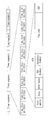
図6は、本実施の形態に係る通信装置1による記憶領域の制御に関する制御フローの一例を示している。図7は、本実施の形態に係る通信装置1における記憶領域の制御の一例を概略的に示している。
図6は、本実施の形態に係る通信装置1による記憶領域の制御に関する制御フローの一例を示している。図7は、本実施の形態に係る通信装置1における記憶領域の制御の一例を概略的に示している。
制御部6は、図7に示したように、被通信装置からの先頭データが伝送されるタイムセグメントの期間では、複数のタイムスロットの全ての期間を記憶部24の記憶領域へのアクセス期間とする(アクセス制限なし)。また、制御部6は、被通信装置からの後続データが伝送されるタイムセグメントの期間では、複数のタイムスロットのうちの1つのタイムスロットの期間を記憶部24の記憶領域へのアクセス期間とするように、アクセス期間を制限する。
通信装置1では、まず、受信回路部2または送信回路部3によって、伝送データの送受信を開始する(ステップS101)。次に、制御部6は、記憶部24の記憶領域へのアクセス期間を、全てのタイムスロットの期間に設定する(ステップS102)。
次に、制御部6は、復号部23の復号結果に基づいて、被通信装置からの伝送データのCRC復号に成功したか否かを判断する(ステップS103)。
CRC復号に成功していない場合(ステップS103;N)には、CRC復号に成功するまで、判断を繰り返す。一方、CRC復号に成功した場合(ステップS103;Y)には、次に、制御部6は、記憶部24の記憶領域へのアクセス期間を、被通信装置からのデータ受信に割り当てられたタイムスロットの期間に設定する(ステップS104)。
次に、制御部6は、復号部23の復号結果に基づいて、被通信装置からの全ての伝送データの受信に成功したか否かを判断する(ステップS105)。全ての伝送データの受信に成功していない場合(ステップS105;N)には、制御部6は、全ての伝送データの受信に成功するまで、判断を繰り返す。一方、全ての伝送データの受信に成功した場合(ステップS105;Y)には、制御部6は、処理を終了する。
このように、制御部6は、被通信装置からの先頭データのCRC復号の成功後に、記憶部24の記憶領域へのアクセス期間を制限する。被通信装置からの後続データの受信期間では、被通信装置に割り当てられたタイムスロットの期間に記憶領域へのアクセスが制限されるため、記憶領域へのアクセス頻度が低減し、消費電力の低減が可能となる。
図8は、本実施の形態に係る通信装置1における再送制御の一例を概略的に示している。
送信回路部3は、被通信装置からの先頭データ(#1)を正常に受信した場合(CRC OK)には、正常に受信したことを示す肯定応答(ACK)を、先頭データが伝送されたタイムセグメントと同一のタイムセグメントの期間内に被通信装置へ返信する。
被通信装置は、肯定応答の返信がなかった場合(CRC NG)には、先頭データの伝送に失敗したタイムセグメントとは異なるタイムセグメントの期間に先頭データを再送し、肯定応答の返信があった場合には、先頭データが伝送されたタイムセグメントとは異なるタイムセグメントの期間に後続データ(#2)を送信する。
後続データ(#2)に続く、他の後続データ(#3),(#4),…がある場合には、他の後続データ(#3),(#4),…に対して同様の再送制御が行われる。
被通信装置では、通信装置1からのACKが観測可能であるため、通信装置1において記憶部24の記憶領域へのアクセス期間が制限されたことを知ることが可能である。
[1.3 効果]
以上のように、本実施の形態によれば、先頭データが伝送されるタイムセグメントの期間における記憶領域へのアクセス期間に対して、後続データが伝送されるタイムセグメントの期間における記憶領域へのアクセス期間の方が短くなるようにアクセス期間を制限するようにしたので、伝送データを記憶する記憶領域へのアクセスが抑制され、消費電力が少なくなり得る。
以上のように、本実施の形態によれば、先頭データが伝送されるタイムセグメントの期間における記憶領域へのアクセス期間に対して、後続データが伝送されるタイムセグメントの期間における記憶領域へのアクセス期間の方が短くなるようにアクセス期間を制限するようにしたので、伝送データを記憶する記憶領域へのアクセスが抑制され、消費電力が少なくなり得る。
なお、本明細書に記載された効果はあくまでも例示であって限定されるものではなく、また他の効果があってもよい。以降の他の実施の形態の効果についても同様である。
<2.第2の実施の形態>
次に、本開示の第2の実施の形態に係る通信装置について説明する。なお、以下では、上記第1の実施の形態に係る通信装置の構成要素と略同じ部分については、同一符号を付し、適宜説明を省略する。
次に、本開示の第2の実施の形態に係る通信装置について説明する。なお、以下では、上記第1の実施の形態に係る通信装置の構成要素と略同じ部分については、同一符号を付し、適宜説明を省略する。
[2.1 構成および動作]
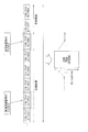
図9は、本実施の形態に係る通信装置による記憶領域の制御に関する制御フローの一例を示している。図10は、本実施の形態に係る通信装置における記憶領域の制御の一例を概略的に示している。
図9は、本実施の形態に係る通信装置による記憶領域の制御に関する制御フローの一例を示している。図10は、本実施の形態に係る通信装置における記憶領域の制御の一例を概略的に示している。
本実施の形態に係る通信装置の構成は、図5の構成と略同様であってもよい。ただし、制御部6による記憶部24の記憶領域へのアクセス期間の制御の仕方が一部異なっている。
上記第1の実施の形態では、制御部6は、被通信装置からの後続データの受信期間では記憶領域へのアクセスを一様に制限するようにしたが、本実施の形態では、複数の後続データを複数のタイムセグメントの期間に亘って受信する場合に、図10に示したように、定期的にアクセス期間の制限を解除する。
アクセス期間の制限後は、被通信装置からのデータを受信するタイムセグメント以外のタイムセグメントでの受信品質が落ちるため、タイムセグメントの同期が破綻する可能性があり得る。このため、本実施の形態に係る通信装置では、記憶部24の記憶領域へのアクセス期間を定期的に全タイムスロットの期間に戻して、タイムセグメントの同期を維持し続けるようにする。これにより、本実施の形態に係る通信装置では、上記第1の実施の形態のように後続データの受信期間で常時、記憶領域を制限する場合に比べて、消費電力は増えるが、タイムセグメントの同期の破綻を防ぐことが可能となる。
図9に示した本実施の形態における制御フローは、図6に示した制御フローに対してステップS104以降の処理が異なっている。
制御部6は、復号部23の復号結果に基づいて、被通信装置からの全ての伝送データの受信に成功したか否かを判断する(ステップS105)。制御部6は、全ての伝送データの受信に成功した場合(ステップS105;Y)には、処理を終了する。
一方、全ての伝送データの受信に成功していない場合(ステップS105;N)には、次に、制御部6は、一定のタイムセグメントが経過したか否かを判断する(ステップS106)。一定のタイムセグメントが経過していない場合(ステップS106;N)には、制御部6は、一定のタイムセグメントが経過するまで、判断を繰り返す。一定のタイムセグメントが経過した場合(ステップS106;Y)には、ステップS102の処理に戻り、記憶部24の記憶領域へのアクセス期間を、全てのタイムスロットの期間に戻す。
その他の構成、動作、ならびに効果は、上記第1の実施の形態に係る通信装置1と略同様であってもよい。
<3.第3の実施の形態>
次に、本開示の第3の実施の形態に係る通信装置について説明する。なお、以下では、上記第1または第2の実施の形態に係る通信装置の構成要素と略同じ部分については、同一符号を付し、適宜説明を省略する。
次に、本開示の第3の実施の形態に係る通信装置について説明する。なお、以下では、上記第1または第2の実施の形態に係る通信装置の構成要素と略同じ部分については、同一符号を付し、適宜説明を省略する。
[3.1 構成および動作]
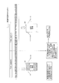
図11は、本実施の形態に係る通信装置による記憶領域の制御に関する制御フローの一例を示している。図12は、本実施の形態に係る通信装置における記憶領域の制御の一例を概略的に示している。
図11は、本実施の形態に係る通信装置による記憶領域の制御に関する制御フローの一例を示している。図12は、本実施の形態に係る通信装置における記憶領域の制御の一例を概略的に示している。
本実施の形態に係る通信装置の構成は、図5の構成と略同様であってもよい。ただし、制御部6による記憶部24の記憶領域へのアクセス期間の制御の仕方が一部異なっている。
上記第1の実施の形態では、制御部6は、被通信装置からの後続データの受信期間では記憶領域へのアクセスを一様に制限するようにしたが、本実施の形態では、所定数のタイムセグメントの期間に亘って後続データの受信に失敗した場合には、図12に示したように、アクセス期間の制限を解除する。
連続で伝送データの受信に失敗している場合は、タイムセグメントの同期が破綻している可能性があり得る。例えば他の通信装置の伝送データのタイミングと重なって干渉している可能性があり得る。そこで、本実施の形態に係る通信装置では、一定のタイムセグメント数、連続で伝送データの受信(CRC復号)に失敗している場合は、記憶部24の記憶領域へのアクセス期間を全タイムスロットの期間に戻す。これにより、上記第2の実施の形態のように定期的に全タイムスロットの期間に戻す手法に比べて、消費電力を低減することが可能となる。
図11に示した本実施の形態における制御フローは、図6に示した制御フローに対してステップS104以降の処理が異なっている。
制御部6は、復号部23の復号結果に基づいて、被通信装置からの全ての伝送データの受信に成功したか否かを判断する(ステップS105)。制御部6は、全ての伝送データの受信に成功した場合(ステップS105;Y)には、処理を終了する。
一方、全ての伝送データの受信に成功していない場合(ステップS105;N)には、次に、制御部6は、一定のタイムセグメント数、連続で伝送データの受信に失敗したか否かを判断する(ステップS107)。一定のタイムセグメント数、連続で伝送データの受信に失敗していない場合(ステップS107;N)には、判断を繰り返す。一定のタイムセグメント数、連続で伝送データの受信に失敗した場合(ステップS107;Y)には、ステップS102の処理に戻り、記憶部24の記憶領域へのアクセス期間を、全てのタイムスロットの期間に戻す。
その他の構成、動作、ならびに効果は、上記第1または第2の実施の形態に係る通信装置と略同様であってもよい。
<4.第4の実施の形態(応用例)>
本開示に係る技術は、様々な製品へ応用することができる。例えば、本開示に係る技術は、自動車、電気自動車、ハイブリッド電気自動車、自動二輪車、自転車、パーソナルモビリティ、飛行機、ドローン、船舶、ロボット、建設機械、農業機械(トラクター)などのいずれかの種類の移動体に搭載される装置として実現されてもよい。
本開示に係る技術は、様々な製品へ応用することができる。例えば、本開示に係る技術は、自動車、電気自動車、ハイブリッド電気自動車、自動二輪車、自転車、パーソナルモビリティ、飛行機、ドローン、船舶、ロボット、建設機械、農業機械(トラクター)などのいずれかの種類の移動体に搭載される装置として実現されてもよい。
なお、以下の説明中、GSMおよびHDMIは登録商標である。
図13は、本開示に係る技術が適用され得る移動体制御システムの一例である車両制御システム7000の概略的な構成例を示すブロック図である。車両制御システム7000は、通信ネットワーク7010を介して接続された複数の電子制御ユニットを備える。図13に示した例では、車両制御システム7000は、駆動系制御ユニット7100、ボディ系制御ユニット7200、バッテリ制御ユニット7300、車外情報検出ユニット7400、車内情報検出ユニット7500、及び統合制御ユニット7600を備える。これらの複数の制御ユニットを接続する通信ネットワーク7010は、例えば、CAN(Controller Area Network)、LIN(Local Interconnect Network)、LAN(Local Area Network)又はFlexRay(登録商標)等の任意の規格に準拠した車載通信ネットワークであってよい。
各制御ユニットは、各種プログラムにしたがって演算処理を行うマイクロコンピュータと、マイクロコンピュータにより実行されるプログラム又は各種演算に用いられるパラメータ等を記憶する記憶部と、各種制御対象の装置を駆動する駆動回路とを備える。各制御ユニットは、通信ネットワーク7010を介して他の制御ユニットとの間で通信を行うためのネットワークI/Fを備えるとともに、車内外の装置又はセンサ等との間で、有線通信又は無線通信により通信を行うための通信I/Fを備える。図13では、統合制御ユニット7600の機能構成として、マイクロコンピュータ7610、汎用通信I/F7620、専用通信I/F7630、測位部7640、ビーコン受信部7650、車内機器I/F7660、音声画像出力部7670、車載ネットワークI/F7680及び記憶部7690が図示されている。他の制御ユニットも同様に、マイクロコンピュータ、通信I/F及び記憶部等を備える。
駆動系制御ユニット7100は、各種プログラムにしたがって車両の駆動系に関連する装置の動作を制御する。例えば、駆動系制御ユニット7100は、内燃機関又は駆動用モータ等の車両の駆動力を発生させるための駆動力発生装置、駆動力を車輪に伝達するための駆動力伝達機構、車両の舵角を調節するステアリング機構、及び、車両の制動力を発生させる制動装置等の制御装置として機能する。駆動系制御ユニット7100は、ABS(Antilock Brake System)又はESC(Electronic Stability Control)等の制御装置としての機能を有してもよい。
駆動系制御ユニット7100には、車両状態検出部7110が接続される。車両状態検出部7110には、例えば、車体の軸回転運動の角速度を検出するジャイロセンサ、車両の加速度を検出する加速度センサ、あるいは、アクセルペダルの操作量、ブレーキペダルの操作量、ステアリングホイールの操舵角、エンジン回転数又は車輪の回転速度等を検出するためのセンサのうちの少なくとも一つが含まれる。駆動系制御ユニット7100は、車両状態検出部7110から入力される信号を用いて演算処理を行い、内燃機関、駆動用モータ、電動パワーステアリング装置又はブレーキ装置等を制御する。
ボディ系制御ユニット7200は、各種プログラムにしたがって車体に装備された各種装置の動作を制御する。例えば、ボディ系制御ユニット7200は、キーレスエントリシステム、スマートキーシステム、パワーウィンドウ装置、あるいは、ヘッドランプ、バックランプ、ブレーキランプ、ウィンカー又はフォグランプ等の各種ランプの制御装置として機能する。この場合、ボディ系制御ユニット7200には、鍵を代替する携帯機から発信される電波又は各種スイッチの信号が入力され得る。ボディ系制御ユニット7200は、これらの電波又は信号の入力を受け付け、車両のドアロック装置、パワーウィンドウ装置、ランプ等を制御する。
バッテリ制御ユニット7300は、各種プログラムにしたがって駆動用モータの電力供給源である二次電池7310を制御する。例えば、バッテリ制御ユニット7300には、二次電池7310を備えたバッテリ装置から、バッテリ温度、バッテリ出力電圧又はバッテリの残存容量等の情報が入力される。バッテリ制御ユニット7300は、これらの信号を用いて演算処理を行い、二次電池7310の温度調節制御又はバッテリ装置に備えられた冷却装置等の制御を行う。
車外情報検出ユニット7400は、車両制御システム7000を搭載した車両の外部の情報を検出する。例えば、車外情報検出ユニット7400には、撮像部7410及び車外情報検出部7420のうちの少なくとも一方が接続される。撮像部7410には、ToF(Time Of Flight)カメラ、ステレオカメラ、単眼カメラ、赤外線カメラ及びその他のカメラのうちの少なくとも一つが含まれる。車外情報検出部7420には、例えば、現在の天候又は気象を検出するための環境センサ、あるいは、車両制御システム7000を搭載した車両の周囲の他の車両、障害物又は歩行者等を検出するための周囲情報検出センサのうちの少なくとも一つが含まれる。
環境センサは、例えば、雨天を検出する雨滴センサ、霧を検出する霧センサ、日照度合いを検出する日照センサ、及び降雪を検出する雪センサのうちの少なくとも一つであってよい。周囲情報検出センサは、超音波センサ、レーダ装置及びLIDAR(Light Detection and Ranging、Laser Imaging Detection and Ranging)装置のうちの少なくとも一つであってよい。これらの撮像部7410及び車外情報検出部7420は、それぞれ独立したセンサないし装置として備えられてもよいし、複数のセンサないし装置が統合された装置として備えられてもよい。
ここで、図14は、撮像部7410及び車外情報検出部7420の設置位置の例を示す。撮像部7910,7912,7914,7916,7918は、例えば、車両7900のフロントノーズ、サイドミラー、リアバンパ、バックドア及び車室内のフロントガラスの上部のうちの少なくとも一つの位置に設けられる。フロントノーズに備えられる撮像部7910及び車室内のフロントガラスの上部に備えられる撮像部7918は、主として車両7900の前方の画像を取得する。サイドミラーに備えられる撮像部7912,7914は、主として車両7900の側方の画像を取得する。リアバンパ又はバックドアに備えられる撮像部7916は、主として車両7900の後方の画像を取得する。車室内のフロントガラスの上部に備えられる撮像部7918は、主として先行車両又は、歩行者、障害物、信号機、交通標識又は車線等の検出に用いられる。
なお、図14には、それぞれの撮像部7910,7912,7914,7916の撮影範囲の一例が示されている。撮像範囲aは、フロントノーズに設けられた撮像部7910の撮像範囲を示し、撮像範囲b,cは、それぞれサイドミラーに設けられた撮像部7912,7914の撮像範囲を示し、撮像範囲dは、リアバンパ又はバックドアに設けられた撮像部7916の撮像範囲を示す。例えば、撮像部7910,7912,7914,7916で撮像された画像データが重ね合わせられることにより、車両7900を上方から見た俯瞰画像が得られる。
車両7900のフロント、リア、サイド、コーナ及び車室内のフロントガラスの上部に設けられる車外情報検出部7920,7922,7924,7926,7928,7930は、例えば超音波センサ又はレーダ装置であってよい。車両7900のフロントノーズ、リアバンパ、バックドア及び車室内のフロントガラスの上部に設けられる車外情報検出部7920,7926,7930は、例えばLIDAR装置であってよい。これらの車外情報検出部7920~7930は、主として先行車両、歩行者又は障害物等の検出に用いられる。
図13に戻って説明を続ける。車外情報検出ユニット7400は、撮像部7410に車外の画像を撮像させるとともに、撮像された画像データを受信する。また、車外情報検出ユニット7400は、接続されている車外情報検出部7420から検出情報を受信する。車外情報検出部7420が超音波センサ、レーダ装置又はLIDAR装置である場合には、車外情報検出ユニット7400は、超音波又は電磁波等を発信させるとともに、受信された反射波の情報を受信する。車外情報検出ユニット7400は、受信した情報に基づいて、人、車、障害物、標識又は路面上の文字等の物体検出処理又は距離検出処理を行ってもよい。車外情報検出ユニット7400は、受信した情報に基づいて、降雨、霧又は路面状況等を認識する環境認識処理を行ってもよい。車外情報検出ユニット7400は、受信した情報に基づいて、車外の物体までの距離を算出してもよい。
また、車外情報検出ユニット7400は、受信した画像データに基づいて、人、車、障害物、標識又は路面上の文字等を認識する画像認識処理又は距離検出処理を行ってもよい。車外情報検出ユニット7400は、受信した画像データに対して歪補正又は位置合わせ等の処理を行うとともに、異なる撮像部7410により撮像された画像データを合成して、俯瞰画像又はパノラマ画像を生成してもよい。車外情報検出ユニット7400は、異なる撮像部7410により撮像された画像データを用いて、視点変換処理を行ってもよい。
車内情報検出ユニット7500は、車内の情報を検出する。車内情報検出ユニット7500には、例えば、運転者の状態を検出する運転者状態検出部7510が接続される。運転者状態検出部7510は、運転者を撮像するカメラ、運転者の生体情報を検出する生体センサ又は車室内の音声を集音するマイク等を含んでもよい。生体センサは、例えば、座面又はステアリングホイール等に設けられ、座席に座った搭乗者又はステアリングホイールを握る運転者の生体情報を検出する。車内情報検出ユニット7500は、運転者状態検出部7510から入力される検出情報に基づいて、運転者の疲労度合い又は集中度合いを算出してもよいし、運転者が居眠りをしていないかを判別してもよい。車内情報検出ユニット7500は、集音された音声信号に対してノイズキャンセリング処理等の処理を行ってもよい。
統合制御ユニット7600は、各種プログラムにしたがって車両制御システム7000内の動作全般を制御する。統合制御ユニット7600には、入力部7800が接続されている。入力部7800は、例えば、タッチパネル、ボタン、マイクロフォン、スイッチ又はレバー等、搭乗者によって入力操作され得る装置によって実現される。統合制御ユニット7600には、マイクロフォンにより入力される音声を音声認識することにより得たデータが入力されてもよい。入力部7800は、例えば、赤外線又はその他の電波を利用したリモートコントロール装置であってもよいし、車両制御システム7000の操作に対応した携帯電話又はPDA(Personal Digital Assistant)等の外部接続機器であってもよい。入力部7800は、例えばカメラであってもよく、その場合搭乗者はジェスチャにより情報を入力することができる。あるいは、搭乗者が装着したウェアラブル装置の動きを検出することで得られたデータが入力されてもよい。さらに、入力部7800は、例えば、上記の入力部7800を用いて搭乗者等により入力された情報に基づいて入力信号を生成し、統合制御ユニット7600に出力する入力制御回路などを含んでもよい。搭乗者等は、この入力部7800を操作することにより、車両制御システム7000に対して各種のデータを入力したり処理動作を指示したりする。
記憶部7690は、マイクロコンピュータにより実行される各種プログラムを記憶するROM(Read Only Memory)、及び各種パラメータ、演算結果又はセンサ値等を記憶するRAM(Random Access Memory)を含んでいてもよい。また、記憶部7690は、HDD(Hard Disc Drive)等の磁気記憶デバイス、半導体記憶デバイス、光記憶デバイス又は光磁気記憶デバイス等によって実現してもよい。
汎用通信I/F7620は、外部環境7750に存在する様々な機器との間の通信を仲介する汎用的な通信I/Fである。汎用通信I/F7620は、GSM(Global System of Mobile communications)、WiMAX、LTE(Long Term Evolution)若しくはLTE-A(LTE-Advanced)などのセルラー通信プロトコル、又は無線LAN(Wi-Fi(登録商標)ともいう)、Bluetooth(登録商標)などのその他の無線通信プロトコルを実装してよい。汎用通信I/F7620は、例えば、基地局又はアクセスポイントを介して、外部ネットワーク(例えば、インターネット、クラウドネットワーク又は事業者固有のネットワーク)上に存在する機器(例えば、アプリケーションサーバ又は制御サーバ)へ接続してもよい。また、汎用通信I/F7620は、例えばP2P(Peer To Peer)技術を用いて、車両の近傍に存在する端末(例えば、運転者、歩行者若しくは店舗の端末、又はMTC(Machine Type Communication)端末)と接続してもよい。
専用通信I/F7630は、車両における使用を目的として策定された通信プロトコルをサポートする通信I/Fである。専用通信I/F7630は、例えば、下位レイヤのIEEE802.11pと上位レイヤのIEEE1609との組合せであるWAVE(Wireless Access in Vehicle Environment)、DSRC(Dedicated Short Range Communications)、又はセルラー通信プロトコルといった標準プロトコルを実装してよい。専用通信I/F7630は、典型的には、車車間(Vehicle to Vehicle)通信、路車間(Vehicle to Infrastructure)通信、車両と家との間(Vehicle to Home)の通信及び歩車間(Vehicle to Pedestrian)通信のうちの1つ以上を含む概念であるV2X通信を遂行する。
測位部7640は、例えば、GNSS(Global Navigation Satellite System)衛星からのGNSS信号(例えば、GPS(Global Positioning System)衛星からのGPS信号)を受信して測位を実行し、車両の緯度、経度及び高度を含む位置情報を生成する。なお、測位部7640は、無線アクセスポイントとの信号の交換により現在位置を特定してもよく、又は測位機能を有する携帯電話、PHS若しくはスマートフォンといった端末から位置情報を取得してもよい。
ビーコン受信部7650は、例えば、道路上に設置された無線局等から発信される電波あるいは電磁波を受信し、現在位置、渋滞、通行止め又は所要時間等の情報を取得する。なお、ビーコン受信部7650の機能は、上述した専用通信I/F7630に含まれてもよい。
車内機器I/F7660は、マイクロコンピュータ7610と車内に存在する様々な車内機器7760との間の接続を仲介する通信インタフェースである。車内機器I/F7660は、無線LAN、Bluetooth(登録商標)、NFC(Near Field Communication)又はWUSB(Wireless USB)といった無線通信プロトコルを用いて無線接続を確立してもよい。また、車内機器I/F7660は、図示しない接続端子(及び、必要であればケーブル)を介して、USB(Universal Serial Bus)、HDMI(High-Definition Multimedia Interface)、又はMHL(Mobile High-definition Link)等の有線接続を確立してもよい。車内機器7760は、例えば、搭乗者が有するモバイル機器若しくはウェアラブル機器、又は車両に搬入され若しくは取り付けられる情報機器のうちの少なくとも1つを含んでいてもよい。また、車内機器7760は、任意の目的地までの経路探索を行うナビゲーション装置を含んでいてもよい。車内機器I/F7660は、これらの車内機器7760との間で、制御信号又はデータ信号を交換する。
車載ネットワークI/F7680は、マイクロコンピュータ7610と通信ネットワーク7010との間の通信を仲介するインタフェースである。車載ネットワークI/F7680は、通信ネットワーク7010によりサポートされる所定のプロトコルに則して、信号等を送受信する。
統合制御ユニット7600のマイクロコンピュータ7610は、汎用通信I/F7620、専用通信I/F7630、測位部7640、ビーコン受信部7650、車内機器I/F7660及び車載ネットワークI/F7680のうちの少なくとも一つを介して取得される情報に基づき、各種プログラムにしたがって、車両制御システム7000を制御する。例えば、マイクロコンピュータ7610は、取得される車内外の情報に基づいて、駆動力発生装置、ステアリング機構又は制動装置の制御目標値を演算し、駆動系制御ユニット7100に対して制御指令を出力してもよい。例えば、マイクロコンピュータ7610は、車両の衝突回避あるいは衝撃緩和、車間距離に基づく追従走行、車速維持走行、車両の衝突警告、又は車両のレーン逸脱警告等を含むADAS(Advanced Driver Assistance System)の機能実現を目的とした協調制御を行ってもよい。また、マイクロコンピュータ7610は、取得される車両の周囲の情報に基づいて駆動力発生装置、ステアリング機構又は制動装置等を制御することにより、運転者の操作に拠らずに自律的に走行する自動運転等を目的とした協調制御を行ってもよい。
マイクロコンピュータ7610は、汎用通信I/F7620、専用通信I/F7630、測位部7640、ビーコン受信部7650、車内機器I/F7660及び車載ネットワークI/F7680のうちの少なくとも一つを介して取得される情報に基づき、車両と周辺の構造物や人物等の物体との間の3次元距離情報を生成し、車両の現在位置の周辺情報を含むローカル地図情報を作成してもよい。また、マイクロコンピュータ7610は、取得される情報に基づき、車両の衝突、歩行者等の近接又は通行止めの道路への進入等の危険を予測し、警告用信号を生成してもよい。警告用信号は、例えば、警告音を発生させたり、警告ランプを点灯させたりするための信号であってよい。
音声画像出力部7670は、車両の搭乗者又は車外に対して、視覚的又は聴覚的に情報を通知することが可能な出力装置へ音声及び画像のうちの少なくとも一方の出力信号を送信する。図13の例では、出力装置として、オーディオスピーカ7710、表示部7720及びインストルメントパネル7730が例示されている。表示部7720は、例えば、オンボードディスプレイ及びヘッドアップディスプレイの少なくとも一つを含んでいてもよい。表示部7720は、AR(Augmented Reality)表示機能を有していてもよい。出力装置は、これらの装置以外の、ヘッドホン、搭乗者が装着する眼鏡型ディスプレイ等のウェアラブルデバイス、プロジェクタ又はランプ等の他の装置であってもよい。出力装置が表示装置の場合、表示装置は、マイクロコンピュータ7610が行った各種処理により得られた結果又は他の制御ユニットから受信された情報を、テキスト、イメージ、表、グラフ等、様々な形式で視覚的に表示する。また、出力装置が音声出力装置の場合、音声出力装置は、再生された音声データ又は音響データ等からなるオーディオ信号をアナログ信号に変換して聴覚的に出力する。
なお、図13に示した例において、通信ネットワーク7010を介して接続された少なくとも二つの制御ユニットが一つの制御ユニットとして一体化されてもよい。あるいは、個々の制御ユニットが、複数の制御ユニットにより構成されてもよい。さらに、車両制御システム7000が、図示されていない別の制御ユニットを備えてもよい。また、上記の説明において、いずれかの制御ユニットが担う機能の一部又は全部を、他の制御ユニットに持たせてもよい。つまり、通信ネットワーク7010を介して情報の送受信がされるようになっていれば、所定の演算処理が、いずれかの制御ユニットで行われるようになってもよい。同様に、いずれかの制御ユニットに接続されているセンサ又は装置が、他の制御ユニットに接続されるとともに、複数の制御ユニットが、通信ネットワーク7010を介して相互に検出情報を送受信してもよい。
以上説明した車両制御システム7000において、本開示の通信装置、および通信システムは、例えば、汎用通信I/F7620を介した、車両の近傍に存在する端末等の外部環境7750との通信に適用することができる。また、車内機器I/F7660を介した、搭乗者が有するモバイル機器若しくはウェアラブル機器等の車内機器7760との通信に適用することができる。
<5.その他の実施の形態>
本開示による技術は、上記各実施の形態の説明に限定されず種々の変形実施が可能である。
本開示による技術は、上記各実施の形態の説明に限定されず種々の変形実施が可能である。
例えば上記各実施の形態における各構成要素は複数に分割されていてもよく、分割された複数の構成要素で機能を異ならせていてもよい。
また、例えば上記各実施の形態における制御フローにおいて、各処理ステップの一部を省略するような制御フローを実行してもよい。また、制御フローには記載しなかった別の処理ステップを追加するような制御フローを実行してもよい。また、制御フローに示した各処理ステップの順序を部分的に入れ替えるような制御フローを実行してもよい。
例えば、本技術は以下のような構成を取ることもできる。
(1)
先頭データと少なくとも1つの後続データとに分割された伝送データを、複数のタイムセグメントの期間に亘って被通信装置から受信する通信回路部と、
少なくとも前記通信回路部で受信した前記伝送データを記憶する記憶領域を有する記憶部と、
前記先頭データが伝送されるタイムセグメントの期間における前記記憶領域へのアクセス期間に対して、前記後続データが伝送されるタイムセグメントの期間における前記記憶領域へのアクセス期間の方が短くなるようにアクセス期間を制限する制御部と
を備える
通信装置。
(2)
前記複数のタイムセグメントはそれぞれ、複数のタイムスロットを含み、
前記被通信装置からの前記伝送データは、前記複数のタイムセグメントのそれぞれにおいて、前記複数のタイムスロットのうちの1つの前記タイムスロットの期間に伝送される
上記(1)に記載の通信装置。
(3)
前記制御部は、前記先頭データが伝送されるタイムセグメントの期間では、前記複数のタイムスロットの全ての期間を前記記憶領域へのアクセス期間とし、前記後続データが伝送されるタイムセグメントの期間では、前記複数のタイムスロットのうちの1つの前記タイムスロットの期間を前記記憶領域へのアクセス期間とする
上記(2)に記載の通信装置。
(4)
前記制御部は、前記通信回路部が、複数の前記後続データを前記複数のタイムセグメントの期間に亘って受信する場合に、定期的に前記アクセス期間の制限を解除する
上記(1)ないし(3)のいずれか1つに記載の通信装置。
(5)
前記制御部は、前記通信回路部が、所定数の前記タイムセグメントの期間に亘って前記後続データの受信に失敗した場合には、前記アクセス期間の制限を解除する
上記(1)ないし(3)のいずれか1つに記載の通信装置。
(6)
前記通信回路部は、前記被通信装置からの前記先頭データを正常に受信した場合には、正常に受信したことを示す肯定応答を、前記先頭データが伝送されたタイムセグメントと同一のタイムセグメントの期間内に前記被通信装置へ返信し、
前記被通信装置は、前記肯定応答の返信がなかった場合には、前記先頭データの伝送に失敗したタイムセグメントとは異なるタイムセグメントの期間に前記先頭データを再送し、前記肯定応答の返信があった場合には、前記先頭データが伝送された前記タイムセグメントとは異なるタイムセグメントの期間に前記後続データを送信する
上記(1)ないし(5)のいずれか1つに記載の通信装置。
(7)
第1の電極および第2の電極を含むアンテナ部、
をさらに備え、
前記通信回路部は、前記アンテナ部を介して人体を通信媒体とする通信を行う
上記(1)ないし(6)のいずれか1つに記載の通信装置。
(8)
第1の通信装置と、
前記第1の通信装置との間で伝送データの伝送を行う第2の通信装置と
を含み、
前記第1の通信装置および前記第2の通信装置のうち、少なくとも一方は、
先頭データと少なくとも1つの後続データとに分割された前記伝送データを、複数のタイムセグメントの期間に亘って受信する通信回路部と、
少なくとも前記通信回路部で受信した前記伝送データを記憶する記憶領域を有する記憶部と、
前記先頭データが伝送されるタイムセグメントの期間における前記記憶領域へのアクセス期間に対して、前記後続データが伝送されるタイムセグメントの期間における前記記憶領域へのアクセス期間の方が短くなるようにアクセス期間を制限する制御部と
を備える
通信システム。
(9)
前記第2の通信装置は、前記第1の通信装置との間で人体を通信媒体とする通信を行う
上記(8)に記載の通信システム。
(1)
先頭データと少なくとも1つの後続データとに分割された伝送データを、複数のタイムセグメントの期間に亘って被通信装置から受信する通信回路部と、
少なくとも前記通信回路部で受信した前記伝送データを記憶する記憶領域を有する記憶部と、
前記先頭データが伝送されるタイムセグメントの期間における前記記憶領域へのアクセス期間に対して、前記後続データが伝送されるタイムセグメントの期間における前記記憶領域へのアクセス期間の方が短くなるようにアクセス期間を制限する制御部と
を備える
通信装置。
(2)
前記複数のタイムセグメントはそれぞれ、複数のタイムスロットを含み、
前記被通信装置からの前記伝送データは、前記複数のタイムセグメントのそれぞれにおいて、前記複数のタイムスロットのうちの1つの前記タイムスロットの期間に伝送される
上記(1)に記載の通信装置。
(3)
前記制御部は、前記先頭データが伝送されるタイムセグメントの期間では、前記複数のタイムスロットの全ての期間を前記記憶領域へのアクセス期間とし、前記後続データが伝送されるタイムセグメントの期間では、前記複数のタイムスロットのうちの1つの前記タイムスロットの期間を前記記憶領域へのアクセス期間とする
上記(2)に記載の通信装置。
(4)
前記制御部は、前記通信回路部が、複数の前記後続データを前記複数のタイムセグメントの期間に亘って受信する場合に、定期的に前記アクセス期間の制限を解除する
上記(1)ないし(3)のいずれか1つに記載の通信装置。
(5)
前記制御部は、前記通信回路部が、所定数の前記タイムセグメントの期間に亘って前記後続データの受信に失敗した場合には、前記アクセス期間の制限を解除する
上記(1)ないし(3)のいずれか1つに記載の通信装置。
(6)
前記通信回路部は、前記被通信装置からの前記先頭データを正常に受信した場合には、正常に受信したことを示す肯定応答を、前記先頭データが伝送されたタイムセグメントと同一のタイムセグメントの期間内に前記被通信装置へ返信し、
前記被通信装置は、前記肯定応答の返信がなかった場合には、前記先頭データの伝送に失敗したタイムセグメントとは異なるタイムセグメントの期間に前記先頭データを再送し、前記肯定応答の返信があった場合には、前記先頭データが伝送された前記タイムセグメントとは異なるタイムセグメントの期間に前記後続データを送信する
上記(1)ないし(5)のいずれか1つに記載の通信装置。
(7)
第1の電極および第2の電極を含むアンテナ部、
をさらに備え、
前記通信回路部は、前記アンテナ部を介して人体を通信媒体とする通信を行う
上記(1)ないし(6)のいずれか1つに記載の通信装置。
(8)
第1の通信装置と、
前記第1の通信装置との間で伝送データの伝送を行う第2の通信装置と
を含み、
前記第1の通信装置および前記第2の通信装置のうち、少なくとも一方は、
先頭データと少なくとも1つの後続データとに分割された前記伝送データを、複数のタイムセグメントの期間に亘って受信する通信回路部と、
少なくとも前記通信回路部で受信した前記伝送データを記憶する記憶領域を有する記憶部と、
前記先頭データが伝送されるタイムセグメントの期間における前記記憶領域へのアクセス期間に対して、前記後続データが伝送されるタイムセグメントの期間における前記記憶領域へのアクセス期間の方が短くなるようにアクセス期間を制限する制御部と
を備える
通信システム。
(9)
前記第2の通信装置は、前記第1の通信装置との間で人体を通信媒体とする通信を行う
上記(8)に記載の通信システム。
本出願は、日本国特許庁において2016年10月13日に出願された日本特許出願番号第2016-201752号を基礎として優先権を主張するものであり、この出願のすべての内容を参照によって本出願に援用する。
当業者であれば、設計上の要件や他の要因に応じて、種々の修正、コンビネーション、サブコンビネーション、および変更を想到し得るが、それらは添付の請求の範囲やその均等物の範囲に含まれるものであることが理解される。
Claims (9)
- 先頭データと少なくとも1つの後続データとに分割された伝送データを、複数のタイムセグメントの期間に亘って被通信装置から受信する通信回路部と、
少なくとも前記通信回路部で受信した前記伝送データを記憶する記憶領域を有する記憶部と、
前記先頭データが伝送されるタイムセグメントの期間における前記記憶領域へのアクセス期間に対して、前記後続データが伝送されるタイムセグメントの期間における前記記憶領域へのアクセス期間の方が短くなるようにアクセス期間を制限する制御部と
を備える
通信装置。 - 前記複数のタイムセグメントはそれぞれ、複数のタイムスロットを含み、
前記被通信装置からの前記伝送データは、前記複数のタイムセグメントのそれぞれにおいて、前記複数のタイムスロットのうちの1つの前記タイムスロットの期間に伝送される
請求項1に記載の通信装置。 - 前記制御部は、前記先頭データが伝送されるタイムセグメントの期間では、前記複数のタイムスロットの全ての期間を前記記憶領域へのアクセス期間とし、前記後続データが伝送されるタイムセグメントの期間では、前記複数のタイムスロットのうちの1つの前記タイムスロットの期間を前記記憶領域へのアクセス期間とする
請求項2に記載の通信装置。 - 前記制御部は、前記通信回路部が、複数の前記後続データを前記複数のタイムセグメントの期間に亘って受信する場合に、定期的に前記アクセス期間の制限を解除する
請求項1に記載の通信装置。 - 前記制御部は、前記通信回路部が、所定数の前記タイムセグメントの期間に亘って前記後続データの受信に失敗した場合には、前記アクセス期間の制限を解除する
請求項1に記載の通信装置。 - 前記通信回路部は、前記被通信装置からの前記先頭データを正常に受信した場合には、正常に受信したことを示す肯定応答を、前記先頭データが伝送されたタイムセグメントと同一のタイムセグメントの期間内に前記被通信装置へ返信し、
前記被通信装置は、前記肯定応答の返信がなかった場合には、前記先頭データの伝送に失敗したタイムセグメントとは異なるタイムセグメントの期間に前記先頭データを再送し、前記肯定応答の返信があった場合には、前記先頭データが伝送された前記タイムセグメントとは異なるタイムセグメントの期間に前記後続データを送信する
請求項1に記載の通信装置。 - 第1の電極および第2の電極を含むアンテナ部、
をさらに備え、
前記通信回路部は、前記アンテナ部を介して人体を通信媒体とする通信を行う
請求項1に記載の通信装置。 - 第1の通信装置と、
前記第1の通信装置との間で伝送データの伝送を行う第2の通信装置と
を含み、
前記第1の通信装置および前記第2の通信装置のうち、少なくとも一方は、
先頭データと少なくとも1つの後続データとに分割された前記伝送データを、複数のタイムセグメントの期間に亘って受信する通信回路部と、
少なくとも前記通信回路部で受信した前記伝送データを記憶する記憶領域を有する記憶部と、
前記先頭データが伝送されるタイムセグメントの期間における前記記憶領域へのアクセス期間に対して、前記後続データが伝送されるタイムセグメントの期間における前記記憶領域へのアクセス期間の方が短くなるようにアクセス期間を制限する制御部と
を備える
通信システム。 - 前記第2の通信装置は、前記第1の通信装置との間で人体を通信媒体とする通信を行う
請求項8に記載の通信システム。
Priority Applications (2)
| Application Number | Priority Date | Filing Date | Title |
|---|---|---|---|
| JP2018544712A JPWO2018070167A1 (ja) | 2016-10-13 | 2017-09-13 | 通信装置、および通信システム |
| US16/327,055 US10797804B2 (en) | 2016-10-13 | 2017-09-13 | Communication unit and communication system |
Applications Claiming Priority (2)
| Application Number | Priority Date | Filing Date | Title |
|---|---|---|---|
| JP2016201752 | 2016-10-13 | ||
| JP2016-201752 | 2016-10-13 |
Publications (1)
| Publication Number | Publication Date |
|---|---|
| WO2018070167A1 true WO2018070167A1 (ja) | 2018-04-19 |
Family
ID=61905450
Family Applications (1)
| Application Number | Title | Priority Date | Filing Date |
|---|---|---|---|
| PCT/JP2017/032959 Ceased WO2018070167A1 (ja) | 2016-10-13 | 2017-09-13 | 通信装置、および通信システム |
Country Status (3)
| Country | Link |
|---|---|
| US (1) | US10797804B2 (ja) |
| JP (1) | JPWO2018070167A1 (ja) |
| WO (1) | WO2018070167A1 (ja) |
Cited By (1)
| Publication number | Priority date | Publication date | Assignee | Title |
|---|---|---|---|---|
| WO2024154586A1 (ja) * | 2023-01-20 | 2024-07-25 | Fdk株式会社 | 送信装置および受信装置 |
Families Citing this family (1)
| Publication number | Priority date | Publication date | Assignee | Title |
|---|---|---|---|---|
| JP6750646B2 (ja) * | 2018-06-07 | 2020-09-02 | トヨタ自動車株式会社 | 車載装置、情報処理方法、および、情報処理プログラム |
Citations (3)
| Publication number | Priority date | Publication date | Assignee | Title |
|---|---|---|---|---|
| JP2000151537A (ja) * | 1998-11-06 | 2000-05-30 | Kyocera Corp | 無線装置の受信信号処理回路 |
| JP2001217750A (ja) * | 2000-02-03 | 2001-08-10 | Matsushita Electric Ind Co Ltd | メモリ回路および同期検波回路 |
| JP2013012916A (ja) * | 2011-06-29 | 2013-01-17 | Panasonic Mobile Communications Co Ltd | 受信装置およびバッファ制御方法 |
Family Cites Families (4)
| Publication number | Priority date | Publication date | Assignee | Title |
|---|---|---|---|---|
| JP2008258767A (ja) | 2007-04-02 | 2008-10-23 | Nec Saitama Ltd | 情報通信端末とメモリ制御方法 |
| US9160496B2 (en) * | 2007-06-29 | 2015-10-13 | Qualcomm Incorporated | Methods and apparatus for H-ARQ process memory management |
| JP2011141770A (ja) | 2010-01-07 | 2011-07-21 | Audio Technica Corp | 信号処理装置、信号処理方法およびワイヤレスマイクロホン |
| US11159440B2 (en) * | 2017-11-22 | 2021-10-26 | Marvell Israel (M.I.S.L) Ltd. | Hybrid packet memory for buffering packets in network devices |
-
2017
- 2017-09-13 US US16/327,055 patent/US10797804B2/en not_active Expired - Fee Related
- 2017-09-13 JP JP2018544712A patent/JPWO2018070167A1/ja active Pending
- 2017-09-13 WO PCT/JP2017/032959 patent/WO2018070167A1/ja not_active Ceased
Patent Citations (3)
| Publication number | Priority date | Publication date | Assignee | Title |
|---|---|---|---|---|
| JP2000151537A (ja) * | 1998-11-06 | 2000-05-30 | Kyocera Corp | 無線装置の受信信号処理回路 |
| JP2001217750A (ja) * | 2000-02-03 | 2001-08-10 | Matsushita Electric Ind Co Ltd | メモリ回路および同期検波回路 |
| JP2013012916A (ja) * | 2011-06-29 | 2013-01-17 | Panasonic Mobile Communications Co Ltd | 受信装置およびバッファ制御方法 |
Cited By (1)
| Publication number | Priority date | Publication date | Assignee | Title |
|---|---|---|---|---|
| WO2024154586A1 (ja) * | 2023-01-20 | 2024-07-25 | Fdk株式会社 | 送信装置および受信装置 |
Also Published As
| Publication number | Publication date |
|---|---|
| US10797804B2 (en) | 2020-10-06 |
| JPWO2018070167A1 (ja) | 2019-08-08 |
| US20190222324A1 (en) | 2019-07-18 |
Similar Documents
| Publication | Publication Date | Title |
|---|---|---|
| WO2017057044A1 (ja) | 情報処理装置及び情報処理方法 | |
| US20210033712A1 (en) | Calibration apparatus, calibration method, and program | |
| EP4470837B1 (en) | Information processing apparatus, information processing method, photographing apparatus, lighting apparatus, and mobile body | |
| US11006283B2 (en) | Wireless communication control device, wireless communication device and wireless communication system | |
| US10911159B2 (en) | Communication unit and communication system | |
| US20190296833A1 (en) | Terminal apparatus and apparatus system | |
| US10917181B2 (en) | Communication apparatus and communication system | |
| US20200349367A1 (en) | Image processing device, image processing method, and program | |
| JP2019036862A (ja) | サーバ装置、記録方法、およびプログラム、並びに情報処理装置 | |
| JP2019036861A (ja) | 情報処理装置、情報処理方法、およびプログラム | |
| US10848271B2 (en) | Communication unit and communication system | |
| US10797804B2 (en) | Communication unit and communication system | |
| CN110999131B (zh) | 通信装置、通信系统和通信方法 | |
| WO2018159304A1 (ja) | 送信装置および通信システム | |
| US20200359412A1 (en) | Communication unit and communication system | |
| WO2021256483A1 (ja) | 制御装置、投影システム、制御方法及びプログラム | |
| WO2018070168A1 (ja) | 通信装置、および通信システム | |
| US10958359B2 (en) | Communication apparatus and communication system | |
| WO2019167578A1 (ja) | 通信装置、および通信システム | |
| WO2020255589A1 (ja) | 情報処理装置、情報処理方法及びプログラム |
Legal Events
| Date | Code | Title | Description |
|---|---|---|---|
| 121 | Ep: the epo has been informed by wipo that ep was designated in this application |
Ref document number: 17860693 Country of ref document: EP Kind code of ref document: A1 |
|
| ENP | Entry into the national phase |
Ref document number: 2018544712 Country of ref document: JP Kind code of ref document: A |
|
| NENP | Non-entry into the national phase |
Ref country code: DE |
|
| 122 | Ep: pct application non-entry in european phase |
Ref document number: 17860693 Country of ref document: EP Kind code of ref document: A1 |