WO2018070136A1 - 投与量調整具、シリンジセットおよびプレフィルドシリンジセット - Google Patents
投与量調整具、シリンジセットおよびプレフィルドシリンジセット Download PDFInfo
- Publication number
- WO2018070136A1 WO2018070136A1 PCT/JP2017/031558 JP2017031558W WO2018070136A1 WO 2018070136 A1 WO2018070136 A1 WO 2018070136A1 JP 2017031558 W JP2017031558 W JP 2017031558W WO 2018070136 A1 WO2018070136 A1 WO 2018070136A1
- Authority
- WO
- WIPO (PCT)
- Prior art keywords
- syringe
- barrel
- plunger
- surrounding body
- dose
- Prior art date
- Legal status (The legal status is an assumption and is not a legal conclusion. Google has not performed a legal analysis and makes no representation as to the accuracy of the status listed.)
- Ceased
Links
Images



Classifications
-
- A—HUMAN NECESSITIES
- A61—MEDICAL OR VETERINARY SCIENCE; HYGIENE
- A61M—DEVICES FOR INTRODUCING MEDIA INTO, OR ONTO, THE BODY; DEVICES FOR TRANSDUCING BODY MEDIA OR FOR TAKING MEDIA FROM THE BODY; DEVICES FOR PRODUCING OR ENDING SLEEP OR STUPOR
- A61M5/00—Devices for bringing media into the body in a subcutaneous, intra-vascular or intramuscular way; Accessories therefor, e.g. filling or cleaning devices, arm-rests
- A61M5/178—Syringes
- A61M5/28—Syringe ampoules or carpules, i.e. ampoules or carpules provided with a needle
-
- A—HUMAN NECESSITIES
- A61—MEDICAL OR VETERINARY SCIENCE; HYGIENE
- A61M—DEVICES FOR INTRODUCING MEDIA INTO, OR ONTO, THE BODY; DEVICES FOR TRANSDUCING BODY MEDIA OR FOR TAKING MEDIA FROM THE BODY; DEVICES FOR PRODUCING OR ENDING SLEEP OR STUPOR
- A61M5/00—Devices for bringing media into the body in a subcutaneous, intra-vascular or intramuscular way; Accessories therefor, e.g. filling or cleaning devices, arm-rests
- A61M5/178—Syringes
- A61M5/31—Details
- A61M5/315—Pistons; Piston-rods; Guiding, blocking or restricting the movement of the rod or piston; Appliances on the rod for facilitating dosing ; Dosing mechanisms
Definitions
- the present invention relates to a dose adjuster capable of precisely adjusting the dose of a drug solution filled in a syringe, and in addition, relates to a syringe set and a prefilled syringe set provided with the dose adjuster.
- the dose is adjusted while the syringe is filled with the drug solution.
- the amount of the plunger pushed into the barrel is adjusted while observing the scale attached to the barrel, and the injection needle attached to the front end of the barrel
- the dosage is adjusted by discharging the surplus drug solution to the outside of the syringe via.
- the dosage adjustment tool is a member having a semi-cylindrical recess for receiving a barrel and a scale formed adjacent to the recess, and using a syringe without a scale on the barrel. When this is administered, it is attached to the barrel to assist a doctor or the like so that the dosage can be adjusted visually.
- the conventional method of adjusting the dose is performed by applying a force so that a doctor or the like pushes the plunger linearly along the axial direction of the barrel. Therefore, the adjustment of the dose depends on the force applied to the plunger, and there is a problem that the precise adjustment is difficult.
- the above-mentioned problem is a problem that arises regardless of whether or not the barrel is graduated, and cannot be solved even when a dose adjuster as disclosed in the above publication is used.
- the present invention has been made to solve the above-described problems, and provides a dose adjusting tool capable of precisely adjusting the dose of a drug solution, and a syringe set and a prefilled syringe set including the same. For the purpose.
- a dose adjuster is used by being attached to a syringe in a state where it is filled with a chemical solution. It has a cylindrical enclosure that can surround the part.
- a first engagement that engages the barrel of the syringe in the mounted state to substantially restrict the movement of the enclosure relative to the barrel to only a spiral motion about the axis of the enclosure in the mounted state.
- the surrounding body moves forward from the rear end side of the syringe toward the front end side of the syringe by engaging with the plunger of the syringe in the mounted state, the plunger follows the surrounding body and moves forward. And a second engaging portion for guiding the plunger so as to move toward the first position.
- the relative position between the barrel and the plunger changes when the enclosure is rotated relative to the barrel in the mounted state. The amount of pushing the plunger into the barrel is changed to adjust the dose.
- the first engagement portion is constituted by a spiral groove provided on the inner peripheral side of the enclosure.
- the dose adjustment tool based on the first aspect of the present invention may further include an auxiliary part in which a protrusion that is screwed into the spiral groove is formed on the outer peripheral side. It is preferable that the auxiliary part can be attached to the syringe barrel in a non-rotatable manner.
- the enclosure is an openable / closable member in which a pair of half cylinders having a half cylinder shape are connected via a hinge portion. It is preferable to be configured.
- the dose adjustment tool based on the second aspect of the present invention is used by being attached to a syringe in a state of being filled with a chemical solution. It has a cylindrical enclosure that can surround the part. A first engaging portion that restricts the surrounding body from moving forward from the rear end side of the syringe toward the front end side of the syringe by engaging with the barrel of the syringe in the mounted state. And a second engagement portion that substantially restricts the movement of the plunger relative to the surrounding body to only a spiral movement around the axis of the surrounding body by engaging with the plunger of the syringe in the mounted state. It has been.
- the relative position of the barrel and the plunger changes when the enclosure is rotated relative to the barrel in the mounted state. The amount of pushing the plunger into the barrel is changed to adjust the dose.
- the second engagement portion is formed of a spiral groove provided on the inner peripheral side of the enclosure.
- the dose adjustment tool based on the second aspect of the present invention may further include an auxiliary part in which a protrusion that is screwed into the spiral groove is formed on the outer peripheral side. It is preferable that the auxiliary part can be attached to the plunger of the syringe in a non-rotatable manner.
- the enclosure is an openable / closable member in which a pair of half cylinders having a half cylinder shape are connected via a hinge portion. It is preferable to be configured.
- the syringe set according to the present invention includes any of the dose adjusting tools based on the first and second aspects of the present invention and a syringe including a barrel and a plunger.
- the prefilled syringe set based on the present invention comprises the syringe set based on the present invention and a chemical solution.
- medical solution is beforehand filled with the inside of the said syringe.
- a dosage adjustment tool capable of precisely adjusting the dosage of a drug solution, and a syringe set and a prefilled syringe set including the same.
- FIG. 1 It is a disassembled perspective view of the prefilled syringe set in Embodiment 1 of this invention.
- FIG. 1 it is a perspective view which shows the state which set the syringe which attached the auxiliary part to the enclosure in an open state.
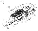
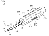
- FIG. 3 is a perspective view showing a state in which the surrounding body is further shifted from the state shown in FIG. 2 to a closed state.
- FIG. 2 It is a disassembled perspective view of the prefilled syringe set in Embodiment 2 of this invention.
- Embodiment 3 It is sectional drawing for demonstrating the adjustment method of the dosage in the prefilled syringe set shown in FIG.
- FIG. 1 is an exploded perspective view of a prefilled syringe set according to Embodiment 1 of the present invention. First, with reference to this FIG. 1, the structure of 1 A of prefilled syringe sets in this Embodiment is demonstrated.
- the prefilled syringe set 1A includes a syringe 100A including a barrel 110, a plunger 120 and an injection needle 130, a dose adjustment tool 200A including an enclosure 210A and an auxiliary part 220A, and a syringe 100A in advance.
- a chemical solution 300 (see FIG. 4A) filled and a cap 400 are provided.
- the dose adjusting tool 200A and the cap 400 are both detachably attached to the syringe 100A.
- the auxiliary part 220A is used by being attached to the barrel 110 of the syringe 100A in the mounted state.
- the surrounding body 210A is used by being attached to the barrel 110 and the plunger 120 of the syringe 100A in the mounted state.
- the barrel 110 includes a main body part 111, a nozzle part 112 (see FIG. 4A) and a luer lock part 113 provided at the front end of the main body part 111, and a flange part 114 provided at the rear end of the main body part 111. have.
- the barrel 110 is made of a transparent resin member, and is constituted by a single member in which the main body portion 111, the nozzle portion 112, the luer lock portion 113, and the flange portion 114 are integrally formed.
- the main body 111 is a portion filled with the chemical solution 300 and has a substantially cylindrical shape.
- the main body 111 is provided with a scale for visually checking the amount of the chemical solution 300 filled in the syringe 100A.
- the syringe 100A of the prefilled syringe set 1A in the present embodiment can be filled with a maximum of 1.0 mL of the chemical solution 300.
- the nozzle part 112 is a part for discharging the chemical solution 300 filled in the barrel 110, and has a substantially cylindrical shape having a diameter smaller than that of the main body part 111.
- a discharge port for discharging the drug solution 300 is provided at the tip of the nozzle portion 112, and the discharge port is formed in the needle tube 131 of the injection needle 130 in a state where the injection needle 130 is attached to the front end of the barrel 110. They are connected (see FIG. 4A).
- the luer lock part 113 is a part for attaching the injection needle 130 to the barrel 110, and is constituted by a substantially cylindrical part located around the nozzle part 112.
- a female screw (see FIG. 4A) for screwing the needle base 132 of the injection needle 130 is provided on the inner peripheral surface of the luer lock portion 113, and the needle base 132 is screwed into the female screw. As a result, the injection needle 130 is attached to the front end of the barrel 110.
- the flange portion 114 is a portion on which a finger is put in order to mainly push the plunger 120 into the barrel 110 during injection, and is formed to project outward from the main body portion 111 in the radial direction.
- the flange portion 114 is also a portion that indirectly engages with the surrounding body 210A via the auxiliary part 220A, and in the present embodiment, has an elongated hexagonal shape that is non-circular in plan view. .
- the plunger 120 has a rod part 121, a flange part 122 provided at the rear end of the rod part 121, and a gasket 123 attached to the front end of the rod part 121.
- the rod portion 121 and the flange portion 122 are made of a resin member, and are configured as a single member formed integrally.
- the gasket 123 is made of a rubber or elastomer member.
- the rod portion 121 is for pushing the chemical solution 300 to the outside from the discharge port of the nozzle portion 112 described above by being pushed into the barrel 110, and has a substantially rod-like shape.
- a coupler to which a gasket 123 is attached is provided at the front end of the rod portion 121 (see FIG. 4A).
- the flange portion 122 is a portion on which a finger is put to push the plunger 120 into the barrel 110 mainly during injection, and is formed to protrude radially outward from the rod portion 121.
- the flange portion 122 is also a portion that directly engages with the surrounding body 210A, and in the present embodiment, has a circular shape in plan view.
- the gasket 123 is a part that seals the inside of the barrel 110 in a liquid-tight manner, and has a bottomed cylindrical shape that covers the coupler provided in the rod portion 121.
- the gasket 123 is also a part for pushing the chemical solution 300 toward the discharge port of the nozzle part 112 by sliding in the main body part 111 when the rod part 121 is pushed.
- the injection needle 130 has a needle tube 131 and a needle base 132 that is located on the rear end side of the needle tube 131 and holds the needle tube 131.
- the needle tube 131 is made of a thin metal tube, and the needle base 132 is made of a resin member.
- the needle tube 131 is fixed to the needle base 132 using, for example, an adhesive.
- the needle tube 131 has a sharp pointed tip.
- the needle tube 131 is for administering to the patient the chemical solution 300 discharged from the discharge port of the nozzle unit 112 by being pierced through the patient's skin.
- the needle base 132 is a part for fixing the injection needle 130 to the barrel 110 and has a cylindrical shape.
- the needle base 132 is provided at its rear end with a protrusion that is screwed into the female screw of the luer lock portion 113 described above.
- the cap 400 is a member for covering the injection needle 130, and is attached to the syringe 100A by being extrapolated to the needle base 132 for safety when not in use. The cap 400 is removed from the syringe 100A at the time of injection.
- the enclosure 210A has a pair of half cylinders 211a and 211b and a pair of hinge portions 212, and is configured to be openable and closable.
- the surrounding body 210A is made of a transparent or non-transparent resin member, and is configured by a single member in which a pair of half-cylinders 211a and 211b and a pair of hinge portions 212 are integrally formed.
- Each of the pair of half-cylinders 211a and 211b has substantially the same shape, and has a cylindrical shape that can surround a predetermined position in the axial direction of the syringe 100A in the closed state.
- the hinge portion 212 is formed of a thin portion that connects the pair of half-cylinders 211a and 211b so that the surrounding body 210A can be opened and closed, and the pair of half-cylinders 211a and 211a that face each other in the closed state. It is provided at a predetermined position of the opening edge of 211b.
- the pair of half cylinders 211a and 211b are provided with claw-shaped locking portions 217a and 217b, respectively.
- the surrounding body 210A has the above-described cylindrical shape, and the closed state is maintained.
- the engagement of the locking portions 217a and 217b is released, the surrounding body 210A takes an open state.
- the locking portions 217a and 217b are opening edges located on the opposite side of the opening edge portion provided with the hinge portion 212 of the pair of half cylinders 211a and 211b that face each other in the closed state. Provided in the department.
- a plurality of protrusions 218 extending linearly are provided on the outer peripheral surfaces of the pair of half cylinders 211a and 211b.
- the plurality of protrusions 218 are parts for preventing a hand holding the enclosure 210A from slipping during a rotation operation of the enclosure 210A described later.
- a wall-shaped barrel holding portion 213 for holding the barrel 110 is provided at one end in the axial direction of the pair of half cylinders 211a and 211b.
- Each of the pair of barrel holding portions 213 is provided with a semicircular cutout portion.
- the cutout portions are combined in a closed state, the main body portion 111 of the barrel 110 is inserted.
- a hole having a shape is formed.
- a wall-shaped plunger holding portion 214 for holding the plunger 120 is provided at a position near the other end in the axial direction of the pair of half cylinders 211a and 211b.
- Each of the pair of plunger holding portions 214 is provided with a semicircular cutout portion. When the cutout portions are combined with each other in the closed state, the rod portion 121 of the plunger 120 is inserted. A hole having a shape is formed. By inserting the rod portion 121 of the plunger 120 into the hole portion, the plunger 120 is held by the surrounding body 210A in the mounted state.
- a groove-shaped first engagement portion 215A is provided on the inner peripheral surface of the portion between the barrel holding portion 213 and the plunger holding portion 214 described above in each of the pair of half cylinders 211a and 211b.
- the groove-shaped first engaging portions 215A are combined with each other in the closed state to form a spiral groove on the inner peripheral side of the surrounding body 210A.
- the first engaging portion 215A constituting the spiral groove is a portion that indirectly engages the barrel 110 via an auxiliary part 220A described later in the mounted state.
- a concave second engaging portion 216A is provided at the other axial end of each of the pair of half cylinders 211a and 211b.
- the concave second engaging portions 216A are combined with each other in the closed state to form a space having a predetermined shape in the surrounding body 210A.
- the second engaging portion 216A constituting the space having the predetermined shape is a portion that directly engages the plunger 120 in the mounted state.
- the auxiliary part 220A has a size and shape that can be accommodated in the enclosure 210A, and is made of a resin member. Specifically, the auxiliary part 220A has a substantially cylindrical shape having an elongated concave cutout at a predetermined position in the circumferential direction.
- the elongated concave cutout portion provided in the auxiliary part 220A constitutes a holding portion 221 that receives the flange portion 114 of the barrel 110, and the holding portion 221 receives the flange portion 114 of the barrel 110 in a state of receiving the flange portion 114. Is held unrotatable.
- the auxiliary part 220 ⁇ / b> A is fixed to the barrel 110 so as not to rotate in the mounted state attached to the flange portion 114 of the barrel 110.
- a plurality of protrusions 222 are provided on the outer peripheral side of the auxiliary part 220A.
- Each of the plurality of protrusions 222 has a spiral shape that can be engaged with the first engagement portion 215A that forms the above-described spiral groove formed in the surrounding body 210A in the mounted state.
- the dose adjustment tool 200A is used by being attached to the syringe 100A in which the drug solution 300 is previously filled.
- the mounting method and usage method will be described below.
- FIG. 2 is a perspective view showing the prefilled syringe set described above in which the syringe with the auxiliary parts attached is set in the open enclosure.
- FIG. 3 is a perspective view showing a state in which the enclosure is further shifted from the state shown in FIG. 2 to the closed state.
- FIG. 2 illustrates a case where the syringe 100A is set in the half cylinder 211a of the pair of half cylinders 211a and 211b.
- the flange part 114 of the barrel 110 is inserted into the holding part 221 formed of an elongated concave cutout provided in the auxiliary part 220A.
- the orientation of the flange portion 114 is matched with the orientation of the holding portion 221, whereby the flange portion 114 is accommodated in the holding portion 221 and the side surface of the flange portion 122 abuts against the wall surface of the holding portion 221.
- the auxiliary part 220A is fixed to the flange portion 114 in a non-rotatable manner.
- the flange portion 122 of the plunger 120 forms a predetermined shaped space provided at the rear end of the half-cylinder 211a.
- the syringe 100A is accommodated in the second engaging portion 216A, and the protrusion 222 of the auxiliary part 220A is then engaged with the first engaging portion 215A constituting the spiral groove of the half cylinder 211a. It mounts on the half cylinder 211a.
- the other one of the pair of half cylinders 211 a and 211 b that is not set with the syringe 100 ⁇ / b> A (here, the half cylinder 211 b corresponds to this) is connected to the pair of hinge parts 212.
- the surrounding body 210 ⁇ / b> A is brought into a closed state by being rotated as a rotation center.
- the engaging portions 217a and 217b provided on the pair of half cylinders 211a and 211b are engaged, and the closed state of the surrounding body 210A is maintained.
- a mounting state in which the dose adjustment tool 200A is mounted on the syringe 100A is realized.
- the portion near the rear end of the syringe 100A is covered with the surrounding body 210A, and the syringe 100A is attached to the portion near the front end of the barrel 110 and the front end of the barrel 110. Only the injection needle 130 is exposed from the surrounding body 210A.
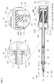
- FIG. 4 is a cross-sectional view for explaining a method of adjusting the dose in the prefilled syringe set described above.
- FIG. 4 (A) is a cross-sectional view of the entire syringe in a state in which the dose adjuster is mounted
- FIGS. 4 (B) and 4 (C) are respectively shown in FIG. 4 (A). It is an enlarged view of areas IVB and IVC.
- the surrounding body 210A when adjusting the dose of the drug solution 300, the surrounding body 210A is rotated relative to the barrel 110 of the syringe 100A in the direction of the arrow DR1 shown in the drawing.
- the barrel 110 of the syringe 100A exposed from the surrounding body 210A is fixedly held with one hand, and the surrounding body 210A is held with the other hand and rotated.
- the barrel 110 of the syringe 100A forms the spiral groove of the surrounding body 210A via the auxiliary part 220A.
- 215A is engaged.
- the protrusion 222 of the auxiliary part 220A that is non-rotatably attached to the flange portion 114 of the barrel 110 engages with the first engagement portion 215A that forms the spiral groove of the enclosure 210A in the closed state. ing.
- the relative movement between the barrel 110 and the surrounding body 210A is substantially limited only to the spiral movement. Therefore, the movement of the surrounding body 210A with respect to the barrel 110 is substantially limited only to the spiral movement around the axis of the surrounding body 210A, and the surrounding body 210A is moved in the direction of the arrow DR1 with respect to the barrel 110.
- the surrounding body 210A moves in the direction of the arrow DR2 shown in FIG. 4A (that is, from the rear end side to the front end side of the syringe 100A). .
- the plunger 120 of the syringe 100A is engaged with the second engagement portion 216A constituting the space having a predetermined shape.
- the flange portion 122 of the plunger 120 is disposed inside the second engagement portion 216A that constitutes a space of a predetermined shape, and the rear surface of the flange portion 122 is in the closed state 210A. It faces the wall surface located at the rear end.
- the flange portion 122 can idle in the second engagement portion 216A that constitutes a space having a predetermined shape.
- the relative movement between the plunger 120 and the surrounding body 210A is limited.
- the surrounding body 210A moves from the rear end side of the syringe 100A toward the front end side. 4A, the plunger 120 follows the movement of the surrounding body 210A by abutting against the wall surface located at the rear end of the surrounding body 210A in which the rear surface of the flange portion 122 is in the closed state. It is guided to move in the direction indicated by the arrow DR3 (ie, from the rear end side to the front end side of the syringe 100A forward).
- the plunger 120 moves forward relative to the barrel 110 by rotating the surrounding body 210A relative to the barrel 110 of the syringe 100A in the attached state in the direction of the arrow DR1 shown in the drawing.
- the relative position between the barrel 110 and the plunger 120 changes, and the pushing amount of the plunger 120 with respect to the barrel 110 is changed.
- the chemical solution 300 filled in the barrel 110 is pushed toward the nozzle portion 112 side by the gasket 123 attached to the front end of the plunger 120, and according to the pushing amount of the plunger 120.
- An amount of the chemical solution 300 is discharged to the outside through the injection needle 130. Therefore, the amount of the chemical solution 300 filled in the syringe 100A can be adjusted to a desired amount by performing the above rotation operation as much as necessary while visually checking the scale attached to the barrel 110. The dose can be adjusted.
- the distance that the plunger 120 moves along the axial direction of the barrel 110 is sufficiently smaller than the operation amount in the rotation direction of the enclosure 210A. Therefore, by using the dose adjustment tool 200A in the present embodiment, the plunger 120 is directly operated without using this, and the plunger 120 is linearly pushed along the axial direction of the barrel 110. Compared to the case, the dosage can be adjusted more precisely.
- the dose adjusting tool capable of precisely adjusting the dose of the drug solution 300 and the prefilled including the same. It can be set as a syringe set.
- the plunger 120 is adjusted by adjusting the pitch and inclination of the first engaging portion 215A constituting the spiral groove provided in the surrounding body 210A and the pitch and inclination of the protrusion 222 provided in the auxiliary part 220A.
- the ratio of the distance moved along the axial direction of the barrel 110 and the operation amount in the rotation direction of the enclosure 210A can be changed. Therefore, by adjusting the ratio appropriately, it is possible to achieve both fine adjustment of dosage and operability.
- the dose adjuster 200A is removed from the syringe 100A, and injection is performed in that state.
- injection can be performed even if this remains attached to the syringe 100A.
- FIG. 5 is an exploded perspective view of the prefilled syringe set according to the second embodiment of the present invention.
- the prefilled syringe set 1B in this Embodiment and the dosage adjustment tool 200B with which it was equipped are demonstrated.
- the prefilled syringe set 1B includes a syringe 100B having a different shape when compared with the prefilled syringe set 1A according to the first embodiment described above.
- the syringe 100 ⁇ / b> B of the prefilled syringe set 1 ⁇ / b> B in the present embodiment can be filled with a maximum of 2.5 mL of the chemical solution 300.
- the prefilled syringe set 1B in the present embodiment is provided with a dosage adjustment tool 200B having a different shape when compared with the prefilled syringe set 1A in the first embodiment described above.
- the dose adjustment tool 200B includes a cylindrical enclosure 210B configured to be openable and closable, and a substantially cylindrical auxiliary part 220B having an elongated concave cutout at a predetermined position in the circumferential direction.
- the surrounding body 210B and the auxiliary part 220B have the same parts as the surrounding body 210A and the auxiliary part 220B of the dose adjusting tool 200A in the first embodiment, although the shapes thereof are different.
- the dose adjuster according to the present invention can be individually designed according to the specifications of the syringe to which the dose adjuster is attached.
- FIG. 6 is an exploded perspective view of the prefilled syringe set according to Embodiment 3 of the present invention
- FIG. 7 is a cross-sectional view for explaining a method for adjusting the dose in the prefilled syringe set shown in FIG.
- FIG. 7 (A) is a cross-sectional view of the entire syringe in a state in which the dose adjuster is mounted
- FIGS. 7 (B) and 7 (C) are shown in FIG. 7 (A), respectively.
- It is an enlarged view of area VIIB and VIIC.
- the prefilled syringe set 1C in this Embodiment and the dosage adjustment tool 200C with which it was equipped are demonstrated.
- the prefilled syringe set 1C according to the present embodiment includes a syringe 100A having the same configuration as the syringe 100A of the prefilled syringe set 1A according to the first embodiment described above.
- the prefilled syringe set 1C in the present embodiment includes a dose adjuster 200C having a configuration different from the dose adjuster 200A of the prefilled syringe set 1A in the first embodiment described above.
- the dose adjustment tool 200C includes a cylindrical enclosure 210C configured to be openable and closable, and a substantially cylindrical auxiliary part 220C having a concave notch at a predetermined position in the circumferential direction.
- a wall-shaped barrel holding portion 213 for holding the barrel 110 is provided at one end in the axial direction of the pair of half-cylinders 211a and 211b constituting the enclosure 210C.
- Each of the concave first engaging portions 215B is provided.
- the concave first engaging portions 215B are combined with each other in the closed state to form a space having a predetermined shape inside the surrounding body 210C.
- the first engagement portion 215B constituting the space having the predetermined shape is a portion that directly engages the barrel 110 in the mounted state.
- a groove-shaped second engagement portion 216B is provided on the inner peripheral surface of the pair of half-cylinders 211a and 211b near the other end in the axial direction.
- the groove-like second engaging portions 216B are combined with each other in the closed state to form a spiral groove on the inner peripheral side of the surrounding body 210C.
- the second engaging portion 216B constituting the spiral groove is a portion that is indirectly engaged with the plunger 120 via an auxiliary part 220C described later in the mounted state.
- the auxiliary part 220 ⁇ / b> C has a size and shape that can be accommodated in the surrounding body 210 ⁇ / b> C, and the concave notch described above constitutes a holding part 221 that receives the flange part 122 of the plunger 120.
- a wall portion located on the front end side is formed with a notch having a shape corresponding to the cross-shaped rod portion 121 of the plunger 120 in cross section.
- Reference numeral 221 holds the flange portion 122 of the plunger 120 in a state in which it is not rotatable.
- the auxiliary part 220 ⁇ / b> C is fixed to the plunger 120 so as not to rotate in the mounted state attached to the flange portion 122 of the plunger 120.
- a plurality of protrusions 222 are provided on the outer peripheral side of the auxiliary part 220C.
- Each of the plurality of protrusions 222 has a spiral shape that can be engaged with the second engagement portion 216B that forms the above-described spiral groove formed in the surrounding body 210C in the mounted state.
- the enclosure 210C is rotated relative to the barrel 110 of the syringe 100A in the direction of the arrow DR1 shown in the figure.
- the barrel 110 of the syringe 100A is engaged with the first engagement portion 215B constituting the space having a predetermined shape.
- the flange portion 114 of the barrel 110 is disposed inside the first engagement portion 215B that constitutes a space of a predetermined shape, and the front surface of the flange portion 114 is the closed body 210C in the closed state. It faces the wall surface located at the front end.
- the flange part 114 can be idled in the inside of the 1st engaging part 215B which comprises the space of a predetermined shape.
- the relative movement between the barrel 110 and the surrounding body 210C is limited. Specifically, the surrounding body 210A moves forward from the rear end side of the syringe 100A toward the front end side. This is restricted by contacting the wall surface located at the front end of the enclosure 210C in which the front surface of the flange portion 114 is in the closed state.
- the plunger 120 of the syringe 100A forms the spiral groove of the surrounding body 210C via the auxiliary part 220C. Is engaged. Specifically, the protrusion 222 of the auxiliary part 220C that is non-rotatably attached to the flange portion 122 of the plunger 120 engages with the second engagement portion 216B that forms the spiral groove of the enclosure 210C in the closed state. ing.
- the relative movement between the plunger 120 and the surrounding body 210C is substantially limited only to the spiral movement. Accordingly, the movement of the plunger 120 with respect to the surrounding body 210C is substantially limited only to the spiral movement around the axis of the surrounding body 210C, and the surrounding body 210C is moved in the direction of the arrow DR1 with respect to the barrel 110.
- the plunger 120 moves in the direction of the arrow DR3 shown in FIG. 4A (that is, from the rear end side to the front end side of the syringe 100A).
- the plunger 120 moves forward relative to the barrel 110 by rotating the surrounding body 210C relative to the barrel 110 of the syringe 100A in the attached state in the direction of the arrow DR1 shown in the drawing.
- the relative position between the barrel 110 and the plunger 120 changes, and the pushing amount of the plunger 120 with respect to the barrel 110 is changed.
- the dose adjustment tool is configured by the surrounding body and the auxiliary parts, and the surrounding body is provided with the flange portion provided on the syringe barrel and the flange portion provided on the plunger.
- the auxiliary part is not necessarily required. That is, it is good also as providing a spiral groove in an enclosure so that it may engage directly with the flange part provided in the barrel of the syringe, or the flange part provided in the plunger, and an auxiliary part becomes unnecessary in that case. .
- an enclosure and auxiliary parts may mainly engage with the flange part provided in the barrel of the syringe, or the flange part provided in the plunger.
- the enclosure and auxiliary parts may also engage with parts other than the barrel and the flange of the plunger.
- the auxiliary part can be configured to be non-rotatably attached to the main body part of the barrel, or the auxiliary part can be configured to be non-rotatably attached to the rod part of the plunger.
- the surrounding body is constituted by a pair of half cylinders connected via the hinge portion.
- the semi-cylindrical body does not need to be constituted by an integral member, and the semi-cylindrical body can be constituted as a separate body, and the surrounding body can be further divided into three or more parts.
- 1A to 1C prefilled syringe set 100A, 100B syringe, 110 barrel, 111 body part, 112 nozzle part, 113 luer lock part, 114 flange part, 120 plunger, 121 rod part, 122 flange part, 123 gasket, 130 injection needle, 131 needle tube, 132 needle base, 200A-200C dose adjustment tool, 210A-210C enclosure, 211a, 211b half cylinder, 212 hinge part, 213 barrel holding part, 214 plunger holding part, 215A, 215B first engaging part 216A, 216B second engaging portion, 217a, 217b locking portion, 218 protrusion, 220A-220C auxiliary parts, 221 holding portion, 222 protrusion, 300 chemicals, 400 cap.
Landscapes
- Health & Medical Sciences (AREA)
- Vascular Medicine (AREA)
- Engineering & Computer Science (AREA)
- Anesthesiology (AREA)
- Biomedical Technology (AREA)
- Heart & Thoracic Surgery (AREA)
- Hematology (AREA)
- Life Sciences & Earth Sciences (AREA)
- Animal Behavior & Ethology (AREA)
- General Health & Medical Sciences (AREA)
- Public Health (AREA)
- Veterinary Medicine (AREA)
- Infusion, Injection, And Reservoir Apparatuses (AREA)
Abstract
投与量調整具(200A)は、囲繞体(210A)を有し、囲繞体(210A)には、装着状態においてバレル(110)に係合することにより、バレル(110)に対する囲繞体(210A)の動きを螺旋運動のみに制限する第1係合部(215A)と、装着状態においてプランジャ(120)に係合することにより、囲繞体(210A)がシリンジ(100A)の前方に移動した場合に囲繞体(210A)に追従してプランジャ(120)が前方に向けて移動するようにプランジャ(120)を案内する第2係合部(216A)とが設けられる。投与量調整具(200A)は、装着状態において囲繞体(210A)がバレル(110)に対して相対的に回転させられることにより、バレル(110)とプランジャ(120)との相対的な位置が変化することでプランジャ(120)のバレル(110)に対する押し込み量を変更し、これにより投与量を調整するものである。
Description
本発明は、シリンジに充填された薬液の投与量を精緻に調整することができる投与量調整具に関し、加えて当該投与量調整具を備えてなるシリンジセットおよびプレフィルドシリンジセットに関する。
通常、シリンジを用いた薬液の投与の際には、シリンジに薬液が充填された状態でその投与量が調整される。具体的には、医師等がバレルを保持した状態でプランジャを操作することにより、バレルに付された目盛りを目視しつつバレルに対するプランジャの押し込み量を調節し、バレルの前端に取付けられた注射針を介して余剰の薬液をシリンジの外部へと排出することで投与量の調整が行なわれる。
また、シリンジに充填された薬液の投与量の調整を行なうための投与量調整具としては、特開2000-93511号公報(特許文献1)に開示のものがある。当該投与量調整具は、バレルを受け入れる半円柱状の凹所が設けられるとともに当該凹所に隣接して目盛りが形成されてなる部材からなり、バレルに目盛りが付されていないシリンジを用いて薬液を投与する場合に、これをバレルに取付けることで医師等が目視によって投与量の調整が行なえるように補助するものである。
従来の投与量の調整方法は、医師等がプランジャをバレルの軸方向に沿って直線的に押し込むように力を作用させることで行なわれる。そのため、投与量の調整が、プランジャに加わる力加減に依存することになり、その精緻な調整が難しい問題があった。
また、万が一プランジャを押し込み過ぎた場合には、必要な投与量に調整することができず、再度の薬液の充填作業が必要になってしまう問題もある。特に、予めバレルに薬液が充填された状態にあるプレフィルドシリンジの場合には、そもそも薬液の再充填を行なうことができないため、当該プレフィルドシリンジの使用ができないことにも繋がってしまう。
上述したような問題は、バレルに目盛りが付されているか否かを問わず生じる問題であり、上記公報に開示される如くの投与量調整具を用いた場合にも解決できるものではない。
したがって、本発明は、上述した問題を解決すべくなされたものであり、薬液の投与量を精緻に調整することができる投与量調整具およびこれを備えてなるシリンジセットおよびプレフィルドシリンジセットを提供することを目的とする。
本発明の第1の局面に基づく投与量調整具は、薬液が充填された状態にあるシリンジに装着されて使用されるものであって、シリンジに装着された装着状態においてシリンジの軸方向における一部を取り囲むことができる筒形状の囲繞体を有している。上記囲繞体には、上記装着状態においてシリンジのバレルに係合することにより、バレルに対する当該囲繞体の動きを当該囲繞体の軸線を中心とした螺旋運動のみに実質的に制限する第1係合部と、上記装着状態においてシリンジのプランジャに係合することにより、当該囲繞体がシリンジの後端側からシリンジの前端側に向けて前方に移動した場合に当該囲繞体に追従してプランジャが前方に向けて移動するようにプランジャを案内する第2係合部とが設けられている。上記本発明の第1の局面に基づく投与量調整具は、上記装着状態において上記囲繞体がバレルに対して相対的に回転させられることにより、バレルとプランジャとの相対的な位置が変化することでプランジャのバレルに対する押し込み量を変更し、これにより投与量を調整するものである。
上記本発明の第1の局面に基づく投与量調整具にあっては、上記第1係合部が、上記囲繞体の内周側に設けられた螺旋溝にて構成されていることが好ましい。
上記本発明の第1の局面に基づく投与量調整具は、外周側に上記螺旋溝に螺合する突条が形成されてなる補助パーツをさらに有していてもよく、その場合には、上記補助パーツが、シリンジのバレルに対して回転不能にその取付けが可能なものであることが好ましい。
上記本発明の第1の局面に基づく投与量調整具にあっては、上記囲繞体が、半筒形状を有する一対の半筒体がヒンジ部を介して接続されてなる開閉可能な部材にて構成されていることが好ましい。
本発明の第2の局面に基づく投与量調整具は、薬液が充填された状態にあるシリンジに装着されて使用されるものであって、シリンジに装着された装着状態においてシリンジの軸方向における一部を取り囲むことができる筒形状の囲繞体を有している。上記囲繞体には、上記装着状態においてシリンジのバレルに係合することにより、当該囲繞体がシリンジの後端側からシリンジの前端側に向けて前方に移動することを制限する第1係合部と、上記装着状態においてシリンジのプランジャに係合することにより、当該囲繞体に対するプランジャの動きを当該囲繞体の軸線を中心とした螺旋運動のみに実質的に制限する第2係合部とが設けられている。上記本発明の第2の局面に基づく投与量調整具は、上記装着状態において上記囲繞体がバレルに対して相対的に回転させられることにより、バレルとプランジャとの相対的な位置が変化することでプランジャのバレルに対する押し込み量を変更し、これにより投与量を調整するものである。
上記本発明の第2の局面に基づく投与量調整具にあっては、上記第2係合部が、上記囲繞体の内周側に設けられた螺旋溝にて構成されていることが好ましい。
上記本発明の第2の局面に基づく投与量調整具は、外周側に上記螺旋溝に螺合する突条が形成されてなる補助パーツをさらに有していてもよく、その場合には、上記補助パーツが、シリンジのプランジャに対して回転不能にその取付けが可能なものであることが好ましい。
上記本発明の第2の局面に基づく投与量調整具にあっては、上記囲繞体が、半筒形状を有する一対の半筒体がヒンジ部を介して接続されてなる開閉可能な部材にて構成されていることが好ましい。
本発明に基づくシリンジセットは、上記本発明の第1および第2の局面に基づく投与量調整具のいずれかと、バレルおよびプランジャを含むシリンジとを備えてなるものである。
本発明に基づくプレフィルドシリンジセットは、上記本発明に基づくシリンジセットと、薬液とを備えてなるものである。上記本発明に基づくプレフィルドシリンジセットにおいては、上記シリンジの内部に上記薬液が予め充填されている。
本発明によれば、薬液の投与量を精緻に調整することができる投与量調整具およびこれを備えてなるシリンジセットおよびプレフィルドシリンジセットとすることができる。
以下、本発明の実施の形態について、図を参照して詳細に説明する。以下に示す実施の形態は、予め薬液が内部に充填されてなるシリンジを備えたプレフィルドシリンジセットおよびこれに具備された投与量調整具に本発明を適用した場合を例示するものであるが、薬液が内部に充填されていないシリンジを備えた通常のシリンジセットおよびこれに具備される投与量調整具や、特にシリンジとセットにされていない投与量調整具に本発明を適用することも当然に可能である。なお、以下に示す実施の形態においては、同一のまたは共通する部分について図中同一の符号を付し、その説明は繰り返さない。
(実施の形態1)
図1は、本発明の実施の形態1におけるプレフィルドシリンジセットの分解斜視図である。まず、この図1を参照して、本実施の形態におけるプレフィルドシリンジセット1Aの構成について説明する。
図1は、本発明の実施の形態1におけるプレフィルドシリンジセットの分解斜視図である。まず、この図1を参照して、本実施の形態におけるプレフィルドシリンジセット1Aの構成について説明する。
図1に示すように、プレフィルドシリンジセット1Aは、バレル110、プランジャ120および注射針130を含むシリンジ100Aと、囲繞体210Aおよび補助パーツ220Aを含む投与量調整具200Aと、シリンジ100Aの内部に予め充填されている薬液300(図4(A)参照)と、キャップ400とを備えている。
このうち、投与量調整具200Aおよびキャップ400は、いずれもシリンジ100Aに対して着脱自在に取付けられる。ここで、投与量調整具200Aのうち、補助パーツ220Aは、装着状態においてシリンジ100Aのバレル110に取付けられて使用される。また、囲繞体210Aは、装着状態においてシリンジ100Aのバレル110およびプランジャ120を取り囲むようにこれらに取付けられて使用される。
バレル110は、本体部111と、本体部111の前端に設けられたノズル部112(図4(A)参照)およびルアーロック部113と、本体部111の後端に設けられたフランジ部114とを有している。バレル110は、透明の樹脂製の部材からなり、上述した本体部111、ノズル部112、ルアーロック部113およびフランジ部114が一体的に形成された単一の部材にて構成されている。
本体部111は、薬液300が充填される部位であり、略円筒状の形状を有している。本体部111には、シリンジ100Aに充填された薬液300の量を目視できる目盛りが付されている。本実施の形態におけるプレフィルドシリンジセット1Aのシリンジ100Aは、最大で1.0mLの薬液300が充填できるものである。
ノズル部112は、バレル110内に充填された薬液300を吐出するための部位であり、本体部111よりも直径の小さい略円筒状の形状を有している。ノズル部112の先端には、薬液300を吐出するための吐出口が設けられており、当該吐出口は、バレル110の前端に注射針130が取付けられた状態において当該注射針130の針管131に接続される(図4(A)参照)。
ルアーロック部113は、バレル110に対して注射針130を取付けるための部位であり、ノズル部112を取り囲んで位置する略円筒状の部位にて構成されている。ルアーロック部113の内周面には、注射針130の針基132を螺合させるための雌ネジ(図4(A)参照)が設けられており、当該雌ネジに針基132が螺合させられることで注射針130がバレル110の前端に取付けられる。
フランジ部114は、主として注射の際にプランジャ120をバレル110に押し込むために手指が掛けられる部位であり、本体部111から径方向外側に向けて突出して形成されている。当該フランジ部114は、補助パーツ220Aを介して囲繞体210Aに間接的に係合する部位でもあり、本実施の形態においては、平面視非円形状の細長略六角形の形状を有している。
プランジャ120は、ロッド部121と、ロッド部121の後端に設けられたフランジ部122と、ロッド部121の前端に取付けられたガスケット123とを有している。ロッド部121およびフランジ部122は、樹脂製の部材からなり、一体的に形成された単一の部材にて構成されている。ガスケット123は、ゴム製またはエラストマ製の部材からなる。
ロッド部121は、バレル110内に向けて押し込まれることで薬液300を上述したノズル部112の吐出口から外部に吐出させるためのものであり、略棒状の形状を有している。ロッド部121の前端には、ガスケット123が取付けられるカプラが設けられている(図4(A)参照)。
フランジ部122は、主として注射の際にプランジャ120をバレル110に押し込むために手指が掛けられる部位であり、ロッド部121から径方向外側に向けて突出して形成されている。当該フランジ部122は、囲繞体210Aに直接的に係合する部位でもあり、本実施の形態においては、平面視円形状を有している。
ガスケット123は、バレル110内を液密に封止する部位であり、ロッド部121に設けられたカプラを覆う有底筒状の形状を有している。また、ガスケット123は、ロッド部121の押し込みに際して本体部111内を摺動することにより、薬液300をノズル部112の吐出口に向けて押し進めるための部位でもある。
注射針130は、針管131と、当該針管131の後端側に位置し、針管131を保持する針基132とを有している。針管131は、金属製の細管からなり、針基132は、樹脂製の部材からなる。針管131は、たとえば接着剤等を用いて針基132に固定されている。
針管131は、鋭利に尖った尖端を有している。針管131は、患者の皮膚に刺通されることにより、ノズル部112の吐出口から吐出される薬液300を患者に投与するためのものである。
針基132は、注射針130をバレル110に固定するための部位であり、筒状の形状を有している。針基132は、その後端に上述したルアーロック部113の雌ネジに螺合する突起が設けられている。
キャップ400は、注射針130を覆うための部材であり、非使用時において安全のために針基132に外挿されることでシリンジ100Aに取付けられる。当該キャップ400は、注射の際にはシリンジ100Aから取り外されることになる。
囲繞体210Aは、一対の半筒体211a,211bと、一対のヒンジ部212とを有しており、開閉可能に構成されている。囲繞体210Aは、透明または非透明の樹脂製の部材からなり、一対の半筒体211a,211bおよび一対のヒンジ部212が一体的に形成された単一の部材にて構成されている。
一対の半筒体211a,211bの各々は、互いにほぼ同一の形状を有しており、閉状態においてシリンジ100Aの軸方向の所定位置を取り囲むことができる筒形状を成す。ヒンジ部212は、囲繞体210Aが開閉可能となるように一対の半筒体211a,211bを相互に接続する薄肉の部位からなり、閉状態において互いに対向することとなる一対の半筒体211a,211bの開口縁部の所定位置に設けられている。
また、一対の半筒体211a,211bには、それぞれ爪状の係止部217a,217bが設けられている。これら係止部217a,217bが互いに係合することにより、囲繞体210Aが上述した筒形状を成し、閉状態が維持されることになる。一方、これら係止部217a,217bの係合が解除されることにより、囲繞体210Aが開状態をとることになる。なお、係止部217a,217bは、閉状態において互いに対向することとなる一対の半筒体211a,211bの、上述したヒンジ部212が設けられた開口縁部とは反対側に位置する開口縁部に設けられている。
さらに、一対の半筒体211a,211bの外周面の各々には、線状に延びる複数の突部218が設けられている。これら複数の突部218は、後述する囲繞体210Aの回転操作の際に、囲繞体210Aを握った手が滑ってしまうことを防止するための部位である。
一対の半筒体211a,211bの軸方向の一端には、バレル110を保持するための壁状のバレル保持部213がそれぞれ設けられている。これら一対のバレル保持部213の各々には、半円形状の切欠き部が設けられており、閉状態においてこれら切欠き部同士が組み合わさることにより、バレル110の本体部111が挿通される円形状の孔部が形成されることになる。当該孔部にバレル110の本体部111が挿通されることにより、装着状態においてバレル110が囲繞体210Aによって保持されることになる。
一対の半筒体211a,211bの軸方向の他端寄りの位置には、プランジャ120を保持するための壁状のプランジャ保持部214がそれぞれ設けられている。これら一対のプランジャ保持部214の各々には、半円形状の切欠き部が設けられており、閉状態においてこれら切欠き部同士が組み合わさることにより、プランジャ120のロッド部121が挿通される円形状の孔部が形成されることになる。当該孔部にプランジャ120のロッド部121が挿通されることにより、装着状態においてプランジャ120が囲繞体210Aによって保持されることになる。
一対の半筒体211a,211bの各々の、上述したバレル保持部213とプランジャ保持部214との間の部分の内周面には、溝状の第1係合部215Aが設けられている。溝状の第1係合部215Aは、閉状態において互いに組み合わさることにより、囲繞体210Aの内周側に螺旋溝を形成する。当該螺旋溝を構成する第1係合部215Aは、装着状態において後述する補助パーツ220Aを介してバレル110に間接的に係合する部位である。
一対の半筒体211a,211bの各々の軸方向の他端には、凹状の第2係合部216Aが設けられている。凹状の第2係合部216Aは、閉状態において互いに組み合わさることにより、囲繞体210Aの内部に所定形状の空間を形成する。当該所定形状の空間を構成する第2係合部216Aは、装着状態においてプランジャ120に直接的に係合する部位である。
補助パーツ220Aは、囲繞体210Aに収容が可能な大きさおよび形状を有しており、樹脂製の部材からなる。具体的には、補助パーツ220Aは、周方向の所定位置に細長凹状の切欠き部を有する略円柱状の形状を有している。
補助パーツ220Aに設けられた細長凹状の切欠き部は、バレル110のフランジ部114を受け入れる保持部221を構成しており、当該保持部221は、バレル110のフランジ部114を受け入れた状態でこれを回転不能に保持する。換言すれば、補助パーツ220Aは、バレル110のフランジ部114に取付けられた装着状態において、バレル110に対して回転不能に固定されることになる。
また、補助パーツ220Aの外周側には、複数の突条222が設けられている。当該複数の突条222の各々は、装着状態において囲繞体210Aの内部に形成される上述した螺旋溝を構成する第1係合部215Aに係合可能な螺旋状の形状を有している。
以上において説明した本実施の形態におけるプレフィルドシリンジセット1Aにおいては、上述したように、投与量調整具200Aが、予め薬液300が内部に充填されたシリンジ100Aに装着されて使用される。以下、その装着方法ならびに使用方法について説明する。
図2は、上述したプレフィルドシリンジセットにおいて、補助パーツを取付けたシリンジを開状態にある囲繞体にセットした状態を示す斜視図である。また、図3は、図2に示す状態からさらに囲繞体を閉状態に移行させた状態を示す斜視図である。まず、これら図2および図3を参照して、投与量調整具200Aのシリンジ100Aへの装着方法について詳説する。
図2に示すように、シリンジ100Aに投与量調整具200Aを装着させるに際しては、まず、注射針130が取付けられたシリンジ100Aからキャップ400を取り外し、次に、当該シリンジ100Aのバレル110のフランジ部114に補助パーツ220Aを取付け、その後、当該補助パーツ220Aが取付けられたシリンジ100Aを囲繞体210Aの一対の半筒体211a,211bの一方にセットする。なお、図2においては、一対の半筒体211a,211bのうちの半筒体211aにシリンジ100Aがセットされた場合を図示している。
ここで、バレル110のフランジ部114に補助パーツ220Aを取付けるに際しては、補助パーツ220Aに設けられた細長凹状の切欠き部からなる保持部221にバレル110のフランジ部114を挿入することで行なう。その際、フランジ部114の向きが保持部221の向きと合わせられることにより、フランジ部114が保持部221に収容されるとともに、フランジ部122の側面が保持部221の壁面に当接することになり、これによって補助パーツ220Aがフランジ部114に対して回転不能に固定されることになる。
また、補助パーツ220Aが取付けられたシリンジ100Aを半筒体211aにセットするに際しては、まず、プランジャ120のフランジ部122が半筒体211aの後端に設けられた所定形状の空間を構成する第2係合部216Aに収容されるようにし、次に、補助パーツ220Aの突条222が半筒体211aの螺旋溝を構成する第1係合部215Aに係合するようにして、シリンジ100Aを半筒体211a上に載置する。これにより、シリンジ100Aの半筒体211aに対する位置決めが行なわれることになり、バレル110の本体部111が半筒体211aのバレル保持部213によって保持されるとともに、プランジャ120のロッド部121が半筒体211aのプランジャ保持部214によって保持されることになる。
次に、図3に示すように、一対の半筒体211a,211bのうちのシリンジ100Aがセットされていない他方(ここでは、半筒体211bがこれに該当する)を一対のヒンジ部212を回転中心として回動させ、囲繞体210Aを閉状態にする。これにより、一対の半筒体211a,211bに設けられた係止部217a,217bが係合することになり、囲繞体210Aの閉状態が維持されることになる。
以上の操作により、シリンジ100Aに投与量調整具200Aが装着された装着状態が実現される。なお、当該装着状態においては、シリンジ100Aの後端寄りの部分が囲繞体210Aによって覆われた状態となり、シリンジ100Aのうちのバレル110の前端寄りの部分と、当該バレル110の前端に取付けられた注射針130とのみが囲繞体210Aから露出した状態となる。
図4は、上述したプレフィルドシリンジセットにおける投与量の調整方法を説明するための断面図である。ここで、図4(A)は、投与量調整具が装着された状態にあるシリンジ全体の断面図であり、図4(B)および図4(C)は、それぞれ図4(A)に示す領域IVB,IVCの拡大図である。次に、この図4と前述の図3とを参照して、投与量調整具200Aの使用方法について詳説する。
図3および図4(A)に示すように、薬液300の投与量を調整するに際しては、シリンジ100Aのバレル110に対して囲繞体210Aを図中に示す矢印DR1方向に向けて相対的に回転させる。具体的には、たとえば囲繞体210Aから露出したシリンジ100Aのバレル110を一方の手で固定的に把持し、他方の手で囲繞体210Aを把持してこれを回転させる。
ここで、図4(B)を参照して、装着状態においては、上述したように、シリンジ100Aのバレル110が、補助パーツ220Aを介して囲繞体210Aの螺旋溝を構成する第1係合部215Aに係合している。具体的には、バレル110のフランジ部114に回転不能に取付けられた補助パーツ220Aの突条222が、閉状態にある囲繞体210Aの螺旋溝を構成する第1係合部215Aに係合している。
これにより、バレル110と囲繞体210Aとの間の相対的な動きが、螺旋運動のみに実質的に制限されることになる。したがって、バレル110に対する囲繞体210Aの動きは、当該囲繞体210Aの軸線を中心とした螺旋運動のみに実質的に制限されることになり、囲繞体210Aをバレル110に対して上記矢印DR1方向に向けて相対的に回転させることにより、囲繞体210Aは、図4(A)中に示す矢印DR2方向に向けて(すなわち、シリンジ100Aの後端側から前端側に向けて)移動することになる。
一方、図4(C)を参照して、装着状態においては、上述したように、シリンジ100Aのプランジャ120が、所定形状の空間を構成する第2係合部216Aに係合している。具体的には、プランジャ120のフランジ部122が、所定形状の空間を構成する第2係合部216Aの内部に配置されており、当該フランジ部122の後面が、閉状態にある囲繞体210Aの後端に位置する壁面に対向している。なお、フランジ部122は、所定形状の空間を構成する第2係合部216Aの内部において空転することができる。
これにより、プランジャ120と囲繞体210Aとの間の相対的な動きが制限されることになるが、具体的には、囲繞体210Aがシリンジ100Aの後端側から前端側に向けて移動した場合に、フランジ部122の後面が閉状態にある囲繞体210Aの後端に位置する上記壁面に当接することにより、プランジャ120が、当該囲繞体210Aの動きに追従して図4(A)中に示す矢印DR3方向に向けて(すなわち、シリンジ100Aの後端側から前端側に前方に向けて)移動するように案内されることになる。
したがって、装着状態においてシリンジ100Aのバレル110に対して囲繞体210Aを図中に示す矢印DR1方向に向けて相対的に回転させることにより、バレル110に対してプランジャ120が前方に向けて移動することになり、これによってバレル110とプランジャ120との相対的な位置が変化し、プランジャ120のバレル110に対する押し込み量が変更されることになる。
そのため、上記回転操作を行なうことにより、バレル110の内部に充填された薬液300がプランジャ120の前端に取付けられたガスケット123によってノズル部112側に向けて押し進められ、プランジャ120の押し込み量に応じた量の薬液300が、注射針130を経由して外部に排出されることになる。したがって、バレル110に付された目盛りを視認しつつ上記回転操作を必要な分だけ行なうことにより、シリンジ100Aに充填された薬液300の量を所望の量に調節できることになり、これによって薬液300の投与量が調整できることになる。
ここで、上述した投与量の調整方法において、プランジャ120がバレル110の軸方向に沿って移動する距離は、囲繞体210Aの回転方向における操作量よりも十分に小さい。そのため、本実施の形態における投与量調整具200Aを用いることにより、これを用いずにプランジャ120を直接的に操作して当該プランジャ120をバレル110の軸方向に沿って直線的に押し込むようにした場合に比べ、より精緻な投与量の調整が行なえることになる。
したがって、本実施の形態におけるプレフィルドシリンジセット1Aおよびこれに具備される投与量調整具200Aとすることにより、薬液300の投与量を精緻に調整することができる投与量調整具およびこれを備えたプレフィルドシリンジセットとすることができる。
なお、上述した囲繞体210Aに設けられる螺旋溝を構成する第1係合部215Aのピッチや傾き等ならびに補助パーツ220Aに設けられる突条222のピッチや傾き等を調節することにより、プランジャ120がバレル110の軸方向に沿って移動する距離と、囲繞体210Aの回転方向における操作量との比率を変更することができる。したがって、当該比率を適宜調節することにより、精緻な投与量の調整と操作性との両立を図ることができる。
また、薬液300の投与量の調整後においては、シリンジ100Aから投与量調整具200Aが取り外され、その状態において注射が行なわれる。なお、投与量調整具200Aのうち、補助パーツ220Aについては、これがシリンジ100Aに取付けられた状態のままでも注射を行なうことができる。
(実施の形態2)
図5は、本発明の実施の形態2におけるプレフィルドシリンジセットの分解斜視図である。以下、この図5を参照して、本実施の形態におけるプレフィルドシリンジセット1Bおよびこれに具備された投与量調整具200Bについて説明する。
図5は、本発明の実施の形態2におけるプレフィルドシリンジセットの分解斜視図である。以下、この図5を参照して、本実施の形態におけるプレフィルドシリンジセット1Bおよびこれに具備された投与量調整具200Bについて説明する。
図5に示すように、本実施の形態におけるプレフィルドシリンジセット1Bは、上述した実施の形態1におけるプレフィルドシリンジセット1Aと比較した場合に、形状の異なるシリンジ100Bを備えている。ここで、本実施の形態におけるプレフィルドシリンジセット1Bのシリンジ100Bは、最大で2.5mLの薬液300が充填できるものである。
これに伴い、本実施の形態におけるプレフィルドシリンジセット1Bは、上述した実施の形態1におけるプレフィルドシリンジセット1Aと比較した場合に、形状の異なる投与量調整具200Bを備えている。
ここで、当該投与量調整具200Bは、開閉可能に構成された筒形状の囲繞体210Bと、周方向の所定位置に細長凹状の切欠き部を有する略円柱状の補助パーツ220Bとを備えており、これら囲繞体210Bおよび補助パーツ220Bは、その形状こそ違えど、上述した実施の形態1における投与量調整具200Aの囲繞体210Aおよび補助パーツ220Bと同様の部位を有している。
そのため、本実施の形態におけるプレフィルドシリンジセット1Bおよびこれに具備される投与量調整具200Bとすることにより、上述した実施の形態1において説明した効果と同様の効果を得ることができる。
このように、本発明に係る投与量調整具は、当該投与量調整具が装着されるシリンジの仕様に応じて個別に設計することができる。
(実施の形態3)
図6は、本発明の実施の形態3におけるプレフィルドシリンジセットの分解斜視図であり、図7は、図6に示すプレフィルドシリンジセットにおける投与量の調整方法を説明するための断面図である。ここで、図7(A)は、投与量調整具が装着された状態にあるシリンジ全体の断面図であり、図7(B)および図7(C)は、それぞれ図7(A)に示す領域VIIB,VIICの拡大図である。以下、これら図6および図7を参照して、本実施の形態におけるプレフィルドシリンジセット1Cおよびこれに具備された投与量調整具200Cについて説明する。
図6は、本発明の実施の形態3におけるプレフィルドシリンジセットの分解斜視図であり、図7は、図6に示すプレフィルドシリンジセットにおける投与量の調整方法を説明するための断面図である。ここで、図7(A)は、投与量調整具が装着された状態にあるシリンジ全体の断面図であり、図7(B)および図7(C)は、それぞれ図7(A)に示す領域VIIB,VIICの拡大図である。以下、これら図6および図7を参照して、本実施の形態におけるプレフィルドシリンジセット1Cおよびこれに具備された投与量調整具200Cについて説明する。
図6に示すように、本実施の形態におけるプレフィルドシリンジセット1Cは、上述した実施の形態1におけるプレフィルドシリンジセット1Aのシリンジ100Aと同様の構成のシリンジ100Aを備えている。一方、本実施の形態におけるプレフィルドシリンジセット1Cは、上述した実施の形態1におけるプレフィルドシリンジセット1Aの投与量調整具200Aとは異なる構成の投与量調整具200Cを備えている。
投与量調整具200Cは、開閉可能に構成された筒形状の囲繞体210Cと、周方向の所定位置に凹状の切欠き部を有する略円柱状の補助パーツ220Cとを備えている。
囲繞体210Cを構成する一対の半筒体211a,211bの軸方向の一端には、バレル110を保持するための壁状のバレル保持部213がそれぞれ設けられており、これに隣接する部分には、凹状の第1係合部215Bがそれぞれ設けられている。凹状の第1係合部215Bは、閉状態において互いに組み合わさることにより、囲繞体210Cの内部に所定形状の空間を形成する。当該所定形状の空間を構成する第1係合部215Bは、装着状態においてバレル110に直接的に係合する部位である。
一対の半筒体211a,211bの軸方向の他端寄りの位置の内周面には、溝状の第2係合部216Bが設けられている。溝状の第2係合部216Bは、閉状態において互いに組み合わさることにより、囲繞体210Cの内周側に螺旋溝を形成する。当該螺旋溝を構成する第2係合部216Bは、装着状態において後述する補助パーツ220Cを介してプランジャ120に間接的に係合する部位である。
補助パーツ220Cは、囲繞体210Cに収容が可能な大きさおよび形状を有しており、上述した凹状の切欠き部は、プランジャ120のフランジ部122を受け入れる保持部221を構成している。当該保持部221を構成する壁部のうち、前端側に位置する壁部には、プランジャ120の断面視十字状のロッド部121に対応した形状の切欠きが形成されており、これにより保持部221は、プランジャ120のフランジ部122を受け入れた状態でこれを回転不能に保持する。換言すれば、補助パーツ220Cは、プランジャ120のフランジ部122に取付けられた装着状態において、プランジャ120に対して回転不能に固定されることになる。
また、補助パーツ220Cの外周側には、複数の突条222が設けられている。当該複数の突条222の各々は、装着状態において囲繞体210Cの内部に形成される上述した螺旋溝を構成する第2係合部216Bに係合可能な螺旋状の形状を有している。
図7(A)に示すように、薬液300の投与量を調整するに際しては、シリンジ100Aのバレル110に対して囲繞体210Cを図中に示す矢印DR1方向に向けて相対的に回転させる。
ここで、図7(B)を参照して、装着状態においては、上述したように、シリンジ100Aのバレル110が、所定形状の空間を構成する第1係合部215Bに係合している。具体的には、バレル110のフランジ部114が、所定形状の空間を構成する第1係合部215Bの内部に配置されており、当該フランジ部114の前面が、閉状態にある囲繞体210Cの前端に位置する壁面に対向している。なお、フランジ部114は、所定形状の空間を構成する第1係合部215Bの内部において空転することができる。
これにより、バレル110と囲繞体210Cとの間の相対的な動きが制限されることになるが、具体的には、囲繞体210Aがシリンジ100Aの後端側から前端側に向けて前方に移動することが、フランジ部114の前面が閉状態にある囲繞体210Cの前端に位置する上記壁面に当接することによって制限されることになる。
一方、図7(C)を参照して、装着状態においては、上述したように、シリンジ100Aのプランジャ120が、補助パーツ220Cを介して囲繞体210Cの螺旋溝を構成する第2係合部216Bに係合している。具体的には、プランジャ120のフランジ部122に回転不能に取付けられた補助パーツ220Cの突条222が、閉状態にある囲繞体210Cの螺旋溝を構成する第2係合部216Bに係合している。
これにより、プランジャ120と囲繞体210Cとの間の相対的な動きが、螺旋運動のみに実質的に制限されることになる。したがって、囲繞体210Cに対するプランジャ120の動きは、当該囲繞体210Cの軸線を中心とした螺旋運動のみに実質的に制限されることになり、囲繞体210Cをバレル110に対して上記矢印DR1方向に向けて相対的に回転させることにより、プランジャ120は、図4(A)中に示す矢印DR3方向に向けて(すなわち、シリンジ100Aの後端側から前端側に向けて)移動することになる。
したがって、装着状態においてシリンジ100Aのバレル110に対して囲繞体210Cを図中に示す矢印DR1方向に向けて相対的に回転させることにより、バレル110に対してプランジャ120が前方に向けて移動することになり、これによってバレル110とプランジャ120との相対的な位置が変化し、プランジャ120のバレル110に対する押し込み量が変更されることになる。
そのため、上記構成のプレフィルドシリンジセット1Cおよびこれに具備される投与量調整具200Cとした場合にも、上述した実施の形態1において説明した効果と同様の効果を得ることができる。
上述した本発明の実施の形態1ないし3においては、投与量調整具を囲繞体と補助パーツとによって構成するとともに、囲繞体がシリンジのバレルに設けられたフランジ部およびプランジャに設けられたフランジ部のいずれか一方に当該補助パーツを介して間接的に係合するように構成した場合を例示して説明を行なったが、補助パーツは必ずしも必要ではない。すなわち、シリンジのバレルに設けられたフランジ部やプランジャに設けられたフランジ部に直接的に係合するように囲繞体に螺旋溝を設けることとしてもよく、その場合には補助パーツは不要になる。
また、上述した本発明の実施の形態1ないし3においては、囲繞体や補助パーツが主としてシリンジのバレルに設けられたフランジ部やプランジャに設けられたフランジ部に係合するように構成した場合を例示して説明を行なったが、囲繞体や補助パーツをバレルやプランジャのフランジ部以外の部分に係合するように構成することも可能である。たとえば、バレルの本体部に補助パーツが回転不能に取付けられるように構成したり、プランジャのロッド部に補助パーツが回転不能に取付けられるように構成したりすることも可能である。
さらには、上述した本発明の実施の形態1ないし3においては、囲繞体をヒンジ部を介して接続された一対の半筒体にて構成した場合を例示して説明を行なったが、必ずしもこれら半筒体が一体の部材にて構成されている必要はなく、別体として半筒体を構成することも可能であるし、囲繞体をさらに3部品以上に分割することも可能である。
このように、今回開示した上記実施の形態はすべての点で例示であって、制限的なものではない。本発明の技術的範囲は請求の範囲によって画定され、また請求の範囲の記載と均等の意味および範囲内でのすべての変更を含むものである。
1A~1C プレフィルドシリンジセット、100A,100B シリンジ、110 バレル、111 本体部、112 ノズル部、113 ルアーロック部、114 フランジ部、120 プランジャ、121 ロッド部、122 フランジ部、123 ガスケット、130 注射針、131 針管、132 針基、200A~200C 投与量調整具、210A~210C 囲繞体、211a,211b 半筒体、212 ヒンジ部、213 バレル保持部、214 プランジャ保持部、215A,215B 第1係合部、216A,216B 第2係合部、217a,217b 係止部、218 突部、220A~220C 補助パーツ、221 保持部、222 突条、300 薬液、400 キャップ。
Claims (10)
- 薬液が充填された状態にあるシリンジに装着されて使用される投与量調整具であって、
シリンジに装着された装着状態においてシリンジの軸方向における一部を取り囲むことができる筒形状の囲繞体を有し、
前記囲繞体には、前記装着状態においてシリンジのバレルに係合することにより、バレルに対する当該囲繞体の動きを当該囲繞体の軸線を中心とした螺旋運動のみに実質的に制限する第1係合部と、前記装着状態においてシリンジのプランジャに係合することにより、当該囲繞体がシリンジの後端側からシリンジの前端側に向けて前方に移動した場合に当該囲繞体に追従してプランジャが前方に向けて移動するようにプランジャを案内する第2係合部とが設けられ、
前記装着状態において前記囲繞体がバレルに対して相対的に回転させられることにより、バレルとプランジャとの相対的な位置が変化することでプランジャのバレルに対する押し込み量を変更し、これにより投与量を調整する、投与量調整具。 - 前記第1係合部が、前記囲繞体の内周側に設けられた螺旋溝からなる、請求項1に記載の投与量調整具。
- 外周側に前記螺旋溝に螺合する突条が形成されてなる補助パーツをさらに有し、
前記補助パーツが、シリンジのバレルに対して回転不能にその取付けが可能なものである、請求項2に記載の投与量調整具。 - 前記囲繞体が、半筒形状を有する一対の半筒体がヒンジ部を介して接続されてなる開閉可能な部材にて構成されている、請求項1から3のいずれかに記載の投与量調整具。
- 薬液が充填された状態にあるシリンジに装着されて使用される投与量調整具であって、
シリンジに装着された装着状態においてシリンジの軸方向における一部を取り囲むことができる筒形状の囲繞体を有し、
前記囲繞体には、前記装着状態においてシリンジのバレルに係合することにより、当該囲繞体がシリンジの後端側からシリンジの前端側に向けて前方に移動することを制限する第1係合部と、前記装着状態においてシリンジのプランジャに係合することにより、当該囲繞体に対するプランジャの動きを当該囲繞体の軸線を中心とした螺旋運動のみに実質的に制限する第2係合部とが設けられ、
前記装着状態において前記囲繞体がバレルに対して相対的に回転させられることにより、バレルとプランジャとの相対的な位置が変化することでプランジャのバレルに対する押し込み量を変更し、これにより投与量を調整する、投与量調整具。 - 前記第2係合部が、前記囲繞体の内周側に設けられた螺旋溝からなる、請求項5に記載の投与量調整具。
- 外周側に前記螺旋溝に螺合する突条が形成されてなる補助パーツをさらに有し、
前記補助パーツが、シリンジのプランジャに対して回転不能にその取付けが可能なものである、請求項6に記載の投与量調整具。 - 前記囲繞体が、半筒形状を有する一対の半筒体がヒンジ部を介して接続されてなる開閉可能な部材にて構成されている、請求項5から7のいずれかに記載の投与量調整具。
- 請求項1から8のいずれかに記載の投与量調整具と、
バレルおよびプランジャを含むシリンジとを備えた、シリンジセット。 - 請求項9に記載のシリンジセットと、
薬液とを備え、
前記シリンジの内部に前記薬液が予め充填されている、プレフィルドシリンジセット。
Priority Applications (1)
| Application Number | Priority Date | Filing Date | Title |
|---|---|---|---|
| JP2018544699A JPWO2018070136A1 (ja) | 2016-10-14 | 2017-09-01 | 投与量調整具、シリンジセットおよびプレフィルドシリンジセット |
Applications Claiming Priority (2)
| Application Number | Priority Date | Filing Date | Title |
|---|---|---|---|
| JP2016-202548 | 2016-10-14 | ||
| JP2016202548 | 2016-10-14 |
Publications (1)
| Publication Number | Publication Date |
|---|---|
| WO2018070136A1 true WO2018070136A1 (ja) | 2018-04-19 |
Family
ID=61906308
Family Applications (1)
| Application Number | Title | Priority Date | Filing Date |
|---|---|---|---|
| PCT/JP2017/031558 Ceased WO2018070136A1 (ja) | 2016-10-14 | 2017-09-01 | 投与量調整具、シリンジセットおよびプレフィルドシリンジセット |
Country Status (2)
| Country | Link |
|---|---|
| JP (1) | JPWO2018070136A1 (ja) |
| WO (1) | WO2018070136A1 (ja) |
Cited By (2)
| Publication number | Priority date | Publication date | Assignee | Title |
|---|---|---|---|---|
| EP3708204A4 (en) * | 2018-11-16 | 2020-10-21 | KORTUC Inc. | SUITABLE SYRINGE FOR HYDROGEN PEROXIDE SOLUTION AND NEEDED |
| CN115884805A (zh) * | 2020-04-21 | 2023-03-31 | 医疗技术概念有限责任公司 | 注射器、制造这种注射器的方法和组件 |
Citations (4)
| Publication number | Priority date | Publication date | Assignee | Title |
|---|---|---|---|---|
| JP2005245999A (ja) * | 2004-03-01 | 2005-09-15 | Tekutoron:Kk | 手動液体注入器 |
| JP2009045501A (ja) * | 1998-09-18 | 2009-03-05 | Soc De Conseils De Recherches & D'applications Scientifiques (Scras) | ペースト状または半固体状の調剤を投与するための注射器 |
| JP2013544169A (ja) * | 2010-11-29 | 2013-12-12 | サノフィ−アベンティス・ドイチュラント・ゲゼルシャフト・ミット・ベシュレンクテル・ハフツング | 薬物送達デバイス |
| JP2014237006A (ja) * | 2003-08-14 | 2014-12-18 | スリーエム イーエスピーイー アーゲー | 2成分材料用のカプセル |
Family Cites Families (1)
| Publication number | Priority date | Publication date | Assignee | Title |
|---|---|---|---|---|
| US7329241B2 (en) * | 2003-02-14 | 2008-02-12 | Valeant Pharmaceuticals North America | Drug delivery system for administering an adjustable preset dose |
-
2017
- 2017-09-01 WO PCT/JP2017/031558 patent/WO2018070136A1/ja not_active Ceased
- 2017-09-01 JP JP2018544699A patent/JPWO2018070136A1/ja active Pending
Patent Citations (4)
| Publication number | Priority date | Publication date | Assignee | Title |
|---|---|---|---|---|
| JP2009045501A (ja) * | 1998-09-18 | 2009-03-05 | Soc De Conseils De Recherches & D'applications Scientifiques (Scras) | ペースト状または半固体状の調剤を投与するための注射器 |
| JP2014237006A (ja) * | 2003-08-14 | 2014-12-18 | スリーエム イーエスピーイー アーゲー | 2成分材料用のカプセル |
| JP2005245999A (ja) * | 2004-03-01 | 2005-09-15 | Tekutoron:Kk | 手動液体注入器 |
| JP2013544169A (ja) * | 2010-11-29 | 2013-12-12 | サノフィ−アベンティス・ドイチュラント・ゲゼルシャフト・ミット・ベシュレンクテル・ハフツング | 薬物送達デバイス |
Cited By (5)
| Publication number | Priority date | Publication date | Assignee | Title |
|---|---|---|---|---|
| EP3708204A4 (en) * | 2018-11-16 | 2020-10-21 | KORTUC Inc. | SUITABLE SYRINGE FOR HYDROGEN PEROXIDE SOLUTION AND NEEDED |
| KR20210065998A (ko) * | 2018-11-16 | 2021-06-04 | 가부시키가이샤 코탁 | 과산화수소 용액에 적합한 주사기 및 키트 |
| KR102574226B1 (ko) | 2018-11-16 | 2023-09-04 | 코탁 재팬 엘엘씨 | 과산화수소 용액에 적합한 주사기 및 키트 |
| EP4461334A2 (en) | 2018-11-16 | 2024-11-13 | KORTUC Inc. | Syringe for storing hydrogen peroxide solution, pre-filled syringe and kit comprising the same |
| CN115884805A (zh) * | 2020-04-21 | 2023-03-31 | 医疗技术概念有限责任公司 | 注射器、制造这种注射器的方法和组件 |
Also Published As
| Publication number | Publication date |
|---|---|
| JPWO2018070136A1 (ja) | 2019-08-08 |
Similar Documents
| Publication | Publication Date | Title |
|---|---|---|
| TWI543788B (zh) | 藥物輸送裝置 | |
| JP4601522B2 (ja) | 2チャンバアンプル用の自動ペン | |
| US20230090486A1 (en) | Injector needle insertion retraction assembly | |
| JP4955772B2 (ja) | いくつかの連結機構を有する注射装置 | |
| TWI598124B (zh) | 針回縮裝置 | |
| EP4076598B1 (en) | Fixed dose injection device | |
| KR100763046B1 (ko) | 고정 용량 약물 분배 장치 | |
| US10426898B2 (en) | Retractable needle assemblies | |
| CA3019104C (en) | Removable actuating cap for use with an auto-injector assembly | |
| JP4834389B2 (ja) | 注射装置 | |
| US8038651B2 (en) | Device with pressure-actuated pistons for dispensing a multiple syringe or multiple cartridge | |
| US20070179451A1 (en) | Safety needle assembly | |
| BR112016007599B1 (pt) | Dispositivo de descarga para um dispensador para descarregar os líquidos farmacêuticos e dispensador para descarregar líquidos farmacêuticos | |
| CN110446513A (zh) | 针套 | |
| EP2990066B1 (en) | Syringe | |
| BR102014011513A2 (pt) | seringa que pode ser travada e método de montagem da mesma | |
| BR112015023007B1 (pt) | Seringa de câmaras múltiplas e dispositivo | |
| JP2022046575A (ja) | シーケンシャルな用量送達のための機構 | |
| JP2015526221A (ja) | 安全ニードルアセンブリ | |
| JPWO2018070136A1 (ja) | 投与量調整具、シリンジセットおよびプレフィルドシリンジセット | |
| CN110960757B (zh) | 注射装置的填充体积管理 | |
| TWI804683B (zh) | 有關物質輸送裝置的改進 | |
| JP6898932B2 (ja) | 薬剤汚染のリスクを低減させるための機構 | |
| BR112013021200B1 (pt) | Dispositivo aplicador | |
| JP2021101866A (ja) | シリンジ用の使用量調整具 |
Legal Events
| Date | Code | Title | Description |
|---|---|---|---|
| 121 | Ep: the epo has been informed by wipo that ep was designated in this application |
Ref document number: 17861026 Country of ref document: EP Kind code of ref document: A1 |
|
| ENP | Entry into the national phase |
Ref document number: 2018544699 Country of ref document: JP Kind code of ref document: A |
|
| NENP | Non-entry into the national phase |
Ref country code: DE |
|
| 122 | Ep: pct application non-entry in european phase |
Ref document number: 17861026 Country of ref document: EP Kind code of ref document: A1 |