WO2018066304A1 - Screw extruder - Google Patents
Screw extruder Download PDFInfo
- Publication number
- WO2018066304A1 WO2018066304A1 PCT/JP2017/032495 JP2017032495W WO2018066304A1 WO 2018066304 A1 WO2018066304 A1 WO 2018066304A1 JP 2017032495 W JP2017032495 W JP 2017032495W WO 2018066304 A1 WO2018066304 A1 WO 2018066304A1
- Authority
- WO
- WIPO (PCT)
- Prior art keywords
- casing
- pressure
- screw type
- type extruder
- measured
- Prior art date
Links
Images


Classifications
-
- B—PERFORMING OPERATIONS; TRANSPORTING
- B29—WORKING OF PLASTICS; WORKING OF SUBSTANCES IN A PLASTIC STATE IN GENERAL
- B29C—SHAPING OR JOINING OF PLASTICS; SHAPING OF MATERIAL IN A PLASTIC STATE, NOT OTHERWISE PROVIDED FOR; AFTER-TREATMENT OF THE SHAPED PRODUCTS, e.g. REPAIRING
- B29C48/00—Extrusion moulding, i.e. expressing the moulding material through a die or nozzle which imparts the desired form; Apparatus therefor
- B29C48/03—Extrusion moulding, i.e. expressing the moulding material through a die or nozzle which imparts the desired form; Apparatus therefor characterised by the shape of the extruded material at extrusion
- B29C48/07—Flat, e.g. panels
- B29C48/08—Flat, e.g. panels flexible, e.g. films
-
- B—PERFORMING OPERATIONS; TRANSPORTING
- B29—WORKING OF PLASTICS; WORKING OF SUBSTANCES IN A PLASTIC STATE IN GENERAL
- B29B—PREPARATION OR PRETREATMENT OF THE MATERIAL TO BE SHAPED; MAKING GRANULES OR PREFORMS; RECOVERY OF PLASTICS OR OTHER CONSTITUENTS OF WASTE MATERIAL CONTAINING PLASTICS
- B29B7/00—Mixing; Kneading
- B29B7/30—Mixing; Kneading continuous, with mechanical mixing or kneading devices
- B29B7/34—Mixing; Kneading continuous, with mechanical mixing or kneading devices with movable mixing or kneading devices
- B29B7/38—Mixing; Kneading continuous, with mechanical mixing or kneading devices with movable mixing or kneading devices rotary
- B29B7/46—Mixing; Kneading continuous, with mechanical mixing or kneading devices with movable mixing or kneading devices rotary with more than one shaft
- B29B7/48—Mixing; Kneading continuous, with mechanical mixing or kneading devices with movable mixing or kneading devices rotary with more than one shaft with intermeshing devices, e.g. screws
- B29B7/484—Mixing; Kneading continuous, with mechanical mixing or kneading devices with movable mixing or kneading devices rotary with more than one shaft with intermeshing devices, e.g. screws with two shafts provided with screws, e.g. one screw being shorter than the other
-
- B—PERFORMING OPERATIONS; TRANSPORTING
- B29—WORKING OF PLASTICS; WORKING OF SUBSTANCES IN A PLASTIC STATE IN GENERAL
- B29B—PREPARATION OR PRETREATMENT OF THE MATERIAL TO BE SHAPED; MAKING GRANULES OR PREFORMS; RECOVERY OF PLASTICS OR OTHER CONSTITUENTS OF WASTE MATERIAL CONTAINING PLASTICS
- B29B7/00—Mixing; Kneading
- B29B7/30—Mixing; Kneading continuous, with mechanical mixing or kneading devices
- B29B7/34—Mixing; Kneading continuous, with mechanical mixing or kneading devices with movable mixing or kneading devices
- B29B7/38—Mixing; Kneading continuous, with mechanical mixing or kneading devices with movable mixing or kneading devices rotary
- B29B7/46—Mixing; Kneading continuous, with mechanical mixing or kneading devices with movable mixing or kneading devices rotary with more than one shaft
- B29B7/48—Mixing; Kneading continuous, with mechanical mixing or kneading devices with movable mixing or kneading devices rotary with more than one shaft with intermeshing devices, e.g. screws
- B29B7/488—Parts, e.g. casings, sealings; Accessories, e.g. flow controlling or throttling devices
- B29B7/489—Screws
-
- B—PERFORMING OPERATIONS; TRANSPORTING
- B29—WORKING OF PLASTICS; WORKING OF SUBSTANCES IN A PLASTIC STATE IN GENERAL
- B29B—PREPARATION OR PRETREATMENT OF THE MATERIAL TO BE SHAPED; MAKING GRANULES OR PREFORMS; RECOVERY OF PLASTICS OR OTHER CONSTITUENTS OF WASTE MATERIAL CONTAINING PLASTICS
- B29B7/00—Mixing; Kneading
- B29B7/30—Mixing; Kneading continuous, with mechanical mixing or kneading devices
- B29B7/34—Mixing; Kneading continuous, with mechanical mixing or kneading devices with movable mixing or kneading devices
- B29B7/52—Mixing; Kneading continuous, with mechanical mixing or kneading devices with movable mixing or kneading devices with rollers or the like, e.g. calenders
-
- B—PERFORMING OPERATIONS; TRANSPORTING
- B29—WORKING OF PLASTICS; WORKING OF SUBSTANCES IN A PLASTIC STATE IN GENERAL
- B29B—PREPARATION OR PRETREATMENT OF THE MATERIAL TO BE SHAPED; MAKING GRANULES OR PREFORMS; RECOVERY OF PLASTICS OR OTHER CONSTITUENTS OF WASTE MATERIAL CONTAINING PLASTICS
- B29B7/00—Mixing; Kneading
- B29B7/30—Mixing; Kneading continuous, with mechanical mixing or kneading devices
- B29B7/58—Component parts, details or accessories; Auxiliary operations
- B29B7/60—Component parts, details or accessories; Auxiliary operations for feeding, e.g. end guides for the incoming material
-
- B—PERFORMING OPERATIONS; TRANSPORTING
- B29—WORKING OF PLASTICS; WORKING OF SUBSTANCES IN A PLASTIC STATE IN GENERAL
- B29B—PREPARATION OR PRETREATMENT OF THE MATERIAL TO BE SHAPED; MAKING GRANULES OR PREFORMS; RECOVERY OF PLASTICS OR OTHER CONSTITUENTS OF WASTE MATERIAL CONTAINING PLASTICS
- B29B7/00—Mixing; Kneading
- B29B7/30—Mixing; Kneading continuous, with mechanical mixing or kneading devices
- B29B7/58—Component parts, details or accessories; Auxiliary operations
- B29B7/72—Measuring, controlling or regulating
- B29B7/728—Measuring data of the driving system, e.g. torque, speed, power, vibration
-
- B—PERFORMING OPERATIONS; TRANSPORTING
- B29—WORKING OF PLASTICS; WORKING OF SUBSTANCES IN A PLASTIC STATE IN GENERAL
- B29B—PREPARATION OR PRETREATMENT OF THE MATERIAL TO BE SHAPED; MAKING GRANULES OR PREFORMS; RECOVERY OF PLASTICS OR OTHER CONSTITUENTS OF WASTE MATERIAL CONTAINING PLASTICS
- B29B7/00—Mixing; Kneading
- B29B7/74—Mixing; Kneading using other mixers or combinations of mixers, e.g. of dissimilar mixers ; Plant
- B29B7/7476—Systems, i.e. flow charts or diagrams; Plants
- B29B7/7495—Systems, i.e. flow charts or diagrams; Plants for mixing rubber
-
- B—PERFORMING OPERATIONS; TRANSPORTING
- B29—WORKING OF PLASTICS; WORKING OF SUBSTANCES IN A PLASTIC STATE IN GENERAL
- B29C—SHAPING OR JOINING OF PLASTICS; SHAPING OF MATERIAL IN A PLASTIC STATE, NOT OTHERWISE PROVIDED FOR; AFTER-TREATMENT OF THE SHAPED PRODUCTS, e.g. REPAIRING
- B29C43/00—Compression moulding, i.e. applying external pressure to flow the moulding material; Apparatus therefor
- B29C43/32—Component parts, details or accessories; Auxiliary operations
- B29C43/34—Feeding the material to the mould or the compression means
-
- B—PERFORMING OPERATIONS; TRANSPORTING
- B29—WORKING OF PLASTICS; WORKING OF SUBSTANCES IN A PLASTIC STATE IN GENERAL
- B29C—SHAPING OR JOINING OF PLASTICS; SHAPING OF MATERIAL IN A PLASTIC STATE, NOT OTHERWISE PROVIDED FOR; AFTER-TREATMENT OF THE SHAPED PRODUCTS, e.g. REPAIRING
- B29C43/00—Compression moulding, i.e. applying external pressure to flow the moulding material; Apparatus therefor
- B29C43/32—Component parts, details or accessories; Auxiliary operations
- B29C43/58—Measuring, controlling or regulating
-
- B—PERFORMING OPERATIONS; TRANSPORTING
- B29—WORKING OF PLASTICS; WORKING OF SUBSTANCES IN A PLASTIC STATE IN GENERAL
- B29C—SHAPING OR JOINING OF PLASTICS; SHAPING OF MATERIAL IN A PLASTIC STATE, NOT OTHERWISE PROVIDED FOR; AFTER-TREATMENT OF THE SHAPED PRODUCTS, e.g. REPAIRING
- B29C48/00—Extrusion moulding, i.e. expressing the moulding material through a die or nozzle which imparts the desired form; Apparatus therefor
- B29C48/25—Component parts, details or accessories; Auxiliary operations
- B29C48/36—Means for plasticising or homogenising the moulding material or forcing it through the nozzle or die
- B29C48/395—Means for plasticising or homogenising the moulding material or forcing it through the nozzle or die using screws surrounded by a cooperating barrel, e.g. single screw extruders
- B29C48/40—Means for plasticising or homogenising the moulding material or forcing it through the nozzle or die using screws surrounded by a cooperating barrel, e.g. single screw extruders using two or more parallel screws or at least two parallel non-intermeshing screws, e.g. twin screw extruders
- B29C48/41—Intermeshing counter-rotating screws
-
- B—PERFORMING OPERATIONS; TRANSPORTING
- B29—WORKING OF PLASTICS; WORKING OF SUBSTANCES IN A PLASTIC STATE IN GENERAL
- B29C—SHAPING OR JOINING OF PLASTICS; SHAPING OF MATERIAL IN A PLASTIC STATE, NOT OTHERWISE PROVIDED FOR; AFTER-TREATMENT OF THE SHAPED PRODUCTS, e.g. REPAIRING
- B29C48/00—Extrusion moulding, i.e. expressing the moulding material through a die or nozzle which imparts the desired form; Apparatus therefor
- B29C48/25—Component parts, details or accessories; Auxiliary operations
- B29C48/92—Measuring, controlling or regulating
-
- B—PERFORMING OPERATIONS; TRANSPORTING
- B29—WORKING OF PLASTICS; WORKING OF SUBSTANCES IN A PLASTIC STATE IN GENERAL
- B29C—SHAPING OR JOINING OF PLASTICS; SHAPING OF MATERIAL IN A PLASTIC STATE, NOT OTHERWISE PROVIDED FOR; AFTER-TREATMENT OF THE SHAPED PRODUCTS, e.g. REPAIRING
- B29C43/00—Compression moulding, i.e. applying external pressure to flow the moulding material; Apparatus therefor
- B29C43/32—Component parts, details or accessories; Auxiliary operations
- B29C43/34—Feeding the material to the mould or the compression means
- B29C2043/3433—Feeding the material to the mould or the compression means using dispensing heads, e.g. extruders, placed over or apart from the moulds
-
- B—PERFORMING OPERATIONS; TRANSPORTING
- B29—WORKING OF PLASTICS; WORKING OF SUBSTANCES IN A PLASTIC STATE IN GENERAL
- B29C—SHAPING OR JOINING OF PLASTICS; SHAPING OF MATERIAL IN A PLASTIC STATE, NOT OTHERWISE PROVIDED FOR; AFTER-TREATMENT OF THE SHAPED PRODUCTS, e.g. REPAIRING
- B29C43/00—Compression moulding, i.e. applying external pressure to flow the moulding material; Apparatus therefor
- B29C43/32—Component parts, details or accessories; Auxiliary operations
- B29C43/58—Measuring, controlling or regulating
- B29C2043/5808—Measuring, controlling or regulating pressure or compressing force
-
- B—PERFORMING OPERATIONS; TRANSPORTING
- B29—WORKING OF PLASTICS; WORKING OF SUBSTANCES IN A PLASTIC STATE IN GENERAL
- B29C—SHAPING OR JOINING OF PLASTICS; SHAPING OF MATERIAL IN A PLASTIC STATE, NOT OTHERWISE PROVIDED FOR; AFTER-TREATMENT OF THE SHAPED PRODUCTS, e.g. REPAIRING
- B29C43/00—Compression moulding, i.e. applying external pressure to flow the moulding material; Apparatus therefor
- B29C43/32—Component parts, details or accessories; Auxiliary operations
- B29C43/58—Measuring, controlling or regulating
- B29C2043/5875—Measuring, controlling or regulating the material feed to the moulds or mould parts, e.g. controlling feed flow, velocity, weight, doses
-
- B—PERFORMING OPERATIONS; TRANSPORTING
- B29—WORKING OF PLASTICS; WORKING OF SUBSTANCES IN A PLASTIC STATE IN GENERAL
- B29C—SHAPING OR JOINING OF PLASTICS; SHAPING OF MATERIAL IN A PLASTIC STATE, NOT OTHERWISE PROVIDED FOR; AFTER-TREATMENT OF THE SHAPED PRODUCTS, e.g. REPAIRING
- B29C2948/00—Indexing scheme relating to extrusion moulding
- B29C2948/92—Measuring, controlling or regulating
- B29C2948/92009—Measured parameter
- B29C2948/92019—Pressure
-
- B—PERFORMING OPERATIONS; TRANSPORTING
- B29—WORKING OF PLASTICS; WORKING OF SUBSTANCES IN A PLASTIC STATE IN GENERAL
- B29C—SHAPING OR JOINING OF PLASTICS; SHAPING OF MATERIAL IN A PLASTIC STATE, NOT OTHERWISE PROVIDED FOR; AFTER-TREATMENT OF THE SHAPED PRODUCTS, e.g. REPAIRING
- B29C2948/00—Indexing scheme relating to extrusion moulding
- B29C2948/92—Measuring, controlling or regulating
- B29C2948/92323—Location or phase of measurement
- B29C2948/92361—Extrusion unit
- B29C2948/9238—Feeding, melting, plasticising or pumping zones, e.g. the melt itself
- B29C2948/924—Barrel or housing
-
- B—PERFORMING OPERATIONS; TRANSPORTING
- B29—WORKING OF PLASTICS; WORKING OF SUBSTANCES IN A PLASTIC STATE IN GENERAL
- B29C—SHAPING OR JOINING OF PLASTICS; SHAPING OF MATERIAL IN A PLASTIC STATE, NOT OTHERWISE PROVIDED FOR; AFTER-TREATMENT OF THE SHAPED PRODUCTS, e.g. REPAIRING
- B29C2948/00—Indexing scheme relating to extrusion moulding
- B29C2948/92—Measuring, controlling or regulating
- B29C2948/92504—Controlled parameter
- B29C2948/92514—Pressure
-
- B—PERFORMING OPERATIONS; TRANSPORTING
- B29—WORKING OF PLASTICS; WORKING OF SUBSTANCES IN A PLASTIC STATE IN GENERAL
- B29C—SHAPING OR JOINING OF PLASTICS; SHAPING OF MATERIAL IN A PLASTIC STATE, NOT OTHERWISE PROVIDED FOR; AFTER-TREATMENT OF THE SHAPED PRODUCTS, e.g. REPAIRING
- B29C2948/00—Indexing scheme relating to extrusion moulding
- B29C2948/92—Measuring, controlling or regulating
- B29C2948/92504—Controlled parameter
- B29C2948/9258—Velocity
- B29C2948/9259—Angular velocity
-
- B—PERFORMING OPERATIONS; TRANSPORTING
- B29—WORKING OF PLASTICS; WORKING OF SUBSTANCES IN A PLASTIC STATE IN GENERAL
- B29C—SHAPING OR JOINING OF PLASTICS; SHAPING OF MATERIAL IN A PLASTIC STATE, NOT OTHERWISE PROVIDED FOR; AFTER-TREATMENT OF THE SHAPED PRODUCTS, e.g. REPAIRING
- B29C2948/00—Indexing scheme relating to extrusion moulding
- B29C2948/92—Measuring, controlling or regulating
- B29C2948/92819—Location or phase of control
- B29C2948/92857—Extrusion unit
- B29C2948/92876—Feeding, melting, plasticising or pumping zones, e.g. the melt itself
- B29C2948/92885—Screw or gear
-
- B—PERFORMING OPERATIONS; TRANSPORTING
- B29—WORKING OF PLASTICS; WORKING OF SUBSTANCES IN A PLASTIC STATE IN GENERAL
- B29C—SHAPING OR JOINING OF PLASTICS; SHAPING OF MATERIAL IN A PLASTIC STATE, NOT OTHERWISE PROVIDED FOR; AFTER-TREATMENT OF THE SHAPED PRODUCTS, e.g. REPAIRING
- B29C2948/00—Indexing scheme relating to extrusion moulding
- B29C2948/92—Measuring, controlling or regulating
- B29C2948/92819—Location or phase of control
- B29C2948/92857—Extrusion unit
- B29C2948/92904—Die; Nozzle zone
-
- B—PERFORMING OPERATIONS; TRANSPORTING
- B29—WORKING OF PLASTICS; WORKING OF SUBSTANCES IN A PLASTIC STATE IN GENERAL
- B29C—SHAPING OR JOINING OF PLASTICS; SHAPING OF MATERIAL IN A PLASTIC STATE, NOT OTHERWISE PROVIDED FOR; AFTER-TREATMENT OF THE SHAPED PRODUCTS, e.g. REPAIRING
- B29C43/00—Compression moulding, i.e. applying external pressure to flow the moulding material; Apparatus therefor
- B29C43/32—Component parts, details or accessories; Auxiliary operations
- B29C43/44—Compression means for making articles of indefinite length
- B29C43/46—Rollers
-
- B—PERFORMING OPERATIONS; TRANSPORTING
- B29—WORKING OF PLASTICS; WORKING OF SUBSTANCES IN A PLASTIC STATE IN GENERAL
- B29C—SHAPING OR JOINING OF PLASTICS; SHAPING OF MATERIAL IN A PLASTIC STATE, NOT OTHERWISE PROVIDED FOR; AFTER-TREATMENT OF THE SHAPED PRODUCTS, e.g. REPAIRING
- B29C48/00—Extrusion moulding, i.e. expressing the moulding material through a die or nozzle which imparts the desired form; Apparatus therefor
- B29C48/001—Combinations of extrusion moulding with other shaping operations
- B29C48/0011—Combinations of extrusion moulding with other shaping operations combined with compression moulding
-
- B—PERFORMING OPERATIONS; TRANSPORTING
- B29—WORKING OF PLASTICS; WORKING OF SUBSTANCES IN A PLASTIC STATE IN GENERAL
- B29C—SHAPING OR JOINING OF PLASTICS; SHAPING OF MATERIAL IN A PLASTIC STATE, NOT OTHERWISE PROVIDED FOR; AFTER-TREATMENT OF THE SHAPED PRODUCTS, e.g. REPAIRING
- B29C48/00—Extrusion moulding, i.e. expressing the moulding material through a die or nozzle which imparts the desired form; Apparatus therefor
- B29C48/25—Component parts, details or accessories; Auxiliary operations
- B29C48/30—Extrusion nozzles or dies
- B29C48/35—Extrusion nozzles or dies with rollers
-
- B—PERFORMING OPERATIONS; TRANSPORTING
- B29—WORKING OF PLASTICS; WORKING OF SUBSTANCES IN A PLASTIC STATE IN GENERAL
- B29C—SHAPING OR JOINING OF PLASTICS; SHAPING OF MATERIAL IN A PLASTIC STATE, NOT OTHERWISE PROVIDED FOR; AFTER-TREATMENT OF THE SHAPED PRODUCTS, e.g. REPAIRING
- B29C48/00—Extrusion moulding, i.e. expressing the moulding material through a die or nozzle which imparts the desired form; Apparatus therefor
- B29C48/25—Component parts, details or accessories; Auxiliary operations
- B29C48/36—Means for plasticising or homogenising the moulding material or forcing it through the nozzle or die
- B29C48/50—Details of extruders
- B29C48/505—Screws
- B29C48/52—Screws with an outer diameter varying along the longitudinal axis, e.g. for obtaining different thread clearance
- B29C48/525—Conical screws
-
- B—PERFORMING OPERATIONS; TRANSPORTING
- B29—WORKING OF PLASTICS; WORKING OF SUBSTANCES IN A PLASTIC STATE IN GENERAL
- B29K—INDEXING SCHEME ASSOCIATED WITH SUBCLASSES B29B, B29C OR B29D, RELATING TO MOULDING MATERIALS OR TO MATERIALS FOR MOULDS, REINFORCEMENTS, FILLERS OR PREFORMED PARTS, e.g. INSERTS
- B29K2021/00—Use of unspecified rubbers as moulding material
-
- B—PERFORMING OPERATIONS; TRANSPORTING
- B29—WORKING OF PLASTICS; WORKING OF SUBSTANCES IN A PLASTIC STATE IN GENERAL
- B29K—INDEXING SCHEME ASSOCIATED WITH SUBCLASSES B29B, B29C OR B29D, RELATING TO MOULDING MATERIALS OR TO MATERIALS FOR MOULDS, REINFORCEMENTS, FILLERS OR PREFORMED PARTS, e.g. INSERTS
- B29K2105/00—Condition, form or state of moulded material or of the material to be shaped
- B29K2105/06—Condition, form or state of moulded material or of the material to be shaped containing reinforcements, fillers or inserts
- B29K2105/16—Fillers
-
- B—PERFORMING OPERATIONS; TRANSPORTING
- B29—WORKING OF PLASTICS; WORKING OF SUBSTANCES IN A PLASTIC STATE IN GENERAL
- B29K—INDEXING SCHEME ASSOCIATED WITH SUBCLASSES B29B, B29C OR B29D, RELATING TO MOULDING MATERIALS OR TO MATERIALS FOR MOULDS, REINFORCEMENTS, FILLERS OR PREFORMED PARTS, e.g. INSERTS
- B29K2509/00—Use of inorganic materials not provided for in groups B29K2503/00 - B29K2507/00, as filler
Definitions
- the present invention relates to a screw type extruder for extruding a kneaded product.
- Extruder that is installed under a kneader for kneading rubber, which is a raw material for tires, and forms into a sheet while continuously extruding rubber (kneaded material) fed from the kneader in an automobile tire manufacturing process Is used.
- a technique related to this type of extrusion molding machine for example, there are those described in Patent Documents 1 and 2 below.
- the sheet forming apparatus described in Patent Literature 1 includes a material supply unit, a material storage unit that temporarily stores the elastic material supplied from the material supply unit, and a material that rolls the elastic material stored in the material storage unit. And a rolling section. Two screws are arrange
- the roller head extruder described in Patent Document 2 includes an extruder main body and a calender roll device that rolls the kneaded rubber extruded from the extruder main body into a sheet shape.
- a buffer lock device is disposed between the extruder main body and the calendar roll device.
- a sensing device for sensing the pressure between the extruder main body and the calendar roll device (head pressure of the extruder main body) is provided in the buffer lock device.
- the speed of the calendar roll and the screw rotation speed of the extruder body are automatically controlled in accordance with the head pressure of the extruder body sensed by the sensing device.
- Patent Document 2 describes that, with this configuration, a rubber sheet having a uniform width can be obtained continuously without the need for troublesome manual control by a skilled worker.
- silica which is a raw material for fuel-efficient tires
- a rubber (kneaded material) containing silica in a high ratio has a problem that it is difficult to form into a sheet form in an extruder. Therefore, it is desired to improve the dispersibility of rubber (kneaded material) not only in the upstream process kneader but also in the extruder.
- In order to improve the dispersibility of rubber (kneaded material) (1) more energy is applied to the kneaded material in the screw arrangement portion for extruding the kneaded material, and (2) in the screw arrangement portion for extruding the kneaded material. It is necessary to stabilize the full state of the kneaded product.
- Patent Documents 1 and 2 do not describe any technique for improving the dispersibility of the kneaded product in any document.
- the speed of the calender roll and the screw rotation speed of the extruder main body are controlled according to the head pressure of the extruder main body, but this control determines the filling state of the kneaded rubber in the extruder main body. It does not stabilize.
- the present invention has been made in view of the above circumstances, and its object is to solve the problem (2) among the problems (1) and (2) described above for improving the dispersibility of the kneaded product. That is, it is to provide a screw type extruder having a configuration capable of stabilizing the full state of the kneaded material in the screw arrangement portion that performs extrusion of the kneaded material.
- a screw-type extruder includes a screw and a casing that accommodates the screw and has a material inlet on the upstream side in the extrusion direction of the kneaded product and a tip side opening on the downstream side.
- a pressure sensor for measuring the pressure inside the casing is provided between the downstream end of the charging port and the front end side opening of the casing, and the pressure sensor measures the pressure. The number of rotations of the screw is controlled in accordance with the applied pressure, It is characterized by that.
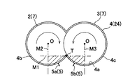
- the inner wall surface of the casing has an outer edge shape in which two circles partially overlap on the same plane in a cross section perpendicular to the extrusion direction of the kneaded product, and the pair of left and right screws Is housed in the casing, and in the cross-section, it is partitioned by an imaginary line extending horizontally from the top of the bottom center of the casing and an imaginary line extending downward from the rotation center of the pair of left and right screws. It is preferable that the pressure inside the casing of the part is measured by the pressure sensor.
- the partition part inside the casing is a part where the pressure is easily stabilized, and the part where the kneading action works most on the material (kneaded material).
- the pressure measurement in this part is also suitable for evaluating the kneading degree of the material (kneaded material).
- a plurality of the pressure sensors are provided so that the respective pressures in the left chamber and the right chamber of the casing can be measured.
- a plurality of the pressure sensors are provided so that pressures at a plurality of locations in the extrusion direction inside the casing can be measured.
- the pressure of the kneaded material discharged from the casing can be stabilized.
- a pair of upper and lower rollers for forming the kneaded material into a sheet shape is disposed on the downstream side of the casing, and a load sensor for measuring a load acting on the rollers is provided on the roller.
- the number of rotations of the roller is preferably controlled by a combination of the pressure measured by the pressure sensor and the load measured by the load sensor.
- the pressure of the kneaded material before the roller can be stabilized.
- a sheet having a stable thickness and width can be manufactured.
- a pair of upper and lower rollers for forming the kneaded material into a sheet shape is disposed on the downstream side of the casing, and the bank portion, which is a portion between the casing and the roller, A bank part pressure sensor for measuring the pressure of the part is further provided, and the rotational speed of the roller is controlled by a combination of the pressure measured by the pressure sensor and the pressure measured by the bank part pressure sensor. Is preferred.
- the pressure of the kneaded material before the roller can be stabilized.
- a sheet having a stable thickness and width can be manufactured.
- the casing has a tapered shape, and the pressure inside the casing on the upstream side of the middle between the downstream side end of the charging port and the front end side opening of the casing is the pressure sensor. It is preferable to measure by.
- the filling of the kneaded material in the casing is achieved by controlling the rotational speed of the screw based on the pressure measured by the pressure sensor described above. Try to stabilize the state. Further, by controlling the number of rotations of the roller based on the combination of the pressure measured by the pressure sensor and the load measured by the load sensor (or the pressure measured by the bank pressure sensor), the sheet thickness And try to stabilize the width.
- the pressure rise gradient in the casing becomes steeper as it approaches the tip.
- the pressure sensor described above is installed at a place where the difference from the tip pressure of the casing is easy to measure, so that the pressure can be measured more appropriately by controlling the rotational speed of the screw. It can be carried out. From such a point, it is preferable to measure the pressure inside the casing upstream from the middle between the downstream end of the material input port and the opening at the front end of the casing. Further, the pressure inside the casing on the upstream side of the middle between the downstream end of the material input port and the opening on the front end side of the casing is sufficiently different from the pressure of the bank part (or the load acting on the roller). Therefore, it is more suitable for controlling the rotational speed of the roller.
- FIG. 2 is a cross-sectional view taken along the line II-II in FIG. 1, and is a vertical cross-sectional view of an extruder with a roller die according to an embodiment of the present invention.
- FIG. 3 is a schematic diagram of a III-III cross section of FIG. 2. It is a pressure distribution figure in a casing downstream part.
- FIG. 4 is a flowchart showing a control flow of a screw rotation speed and a roller rotation speed of the extruder with a roller die shown in FIGS. 1 to 3.
- FIG. 4 is a flowchart showing a control flow of a screw rotation speed and a roller rotation speed of the extruder with a roller die shown in FIGS. 1 to 3.
- a screw type extruder shown in the following embodiment is a screw extruder with a roller die (hereinafter referred to as “an extruder with a roller die”) that extrudes a kneaded material of a polymer material such as rubber into a sheet shape.
- the screw-type extruder of the present invention can also be used in a machine called a pelletizer that extrudes a kneaded material of a polymer material from a die having a large number of circular holes and then cuts it into a cylindrical pellet.
- the extruder 1 with a roller die has a pair of left and right screws 2 and 3 that extrude the kneaded material, and a casing 4 that accommodates the screws 2 and 3.
- a total of two rollers 9 and 10 in a pair are arranged.
- a portion between the casing 4 and the rollers 9 and 10 is referred to as a bank unit 11, and the kneaded material extruded by the screws 2 and 3 accumulates in the bank unit 11. Note that the bank unit 11 is closed.
- rollers 9 and 10 are coupled so as to rotate in opposite directions, and are rotated at the same rotational speed (rotational speed) by one driving means (not shown).
- the rollers 9 and 10 are for rolling the kneaded material into a sheet shape and are called roller dies.
- Each of the screws 2 and 3 has a shaft portion 6 and a spiral flight 7 provided on the outer peripheral surface of the shaft portion 6.
- the screw 2 and the screw 3 are screws having the same shape and dimensions except that the twisting angles of the flights are opposite to each other.
- the screws 2 and 3 are coupled so as to rotate in opposite directions, and are rotated at the same rotational speed by a single driving means (not shown).
- the casing 4 has a tapered shape from the upstream side to the downstream side in the extrusion direction of the kneaded product, and is surrounded by a casing upstream portion 14 provided with a material (kneaded product) inlet 15 at an upper portion and surrounded by a wall surface. And a broken casing downstream portion 24.
- a kneaded material such as rubber supplied to the charging port 15 from above is extruded into the bank unit 11 by screws 2 and 3 that rotate in opposite directions, and then passes between the rollers 9 and 10 to form a sheet. Molded.
- the inner wall surface of the casing 4 has an outer edge shape (glasses shape) in which two circles partially overlap on the same plane in a cross section perpendicular to the extrusion direction of the kneaded product.
- the screw 2 is accommodated in the left chamber 4b of the casing 4, and the screw 3 is accommodated in the right chamber 4c.
- Two pressure sensors 5 (5a, 5b) are attached to the bottom of the casing 4.
- a pressure sensor 5a is attached to the left chamber 4b side, and a pressure sensor 5b is attached to the right chamber 4c side.
- the pressure inside the casing 4 (pressure of the kneaded material) is measured by the pressure sensor 5 (5a, 5b).
- the pressure sensor 5 (5 a, 5 b) has a casing 4 in the space S between the downstream end 15 a of the inlet 15 and the front end opening of the casing 4. It is attached to the bottom.
- the pressure sensor 5 (5a, 5b) is attached to the bottom portion of the casing downstream portion 24 that is the downstream portion of the casing 4 and is surrounded by a wall surface. More preferably, as in the present embodiment, the pressure sensor 5 (5a, 5b) is located between the downstream end 15a of the inlet 15 and the front end opening of the casing 4, and in the middle of S therebetween. It is attached to the bottom of the casing 4 in the range S1 portion that is upstream of the region.
- each of the imaginary line M ⁇ b> 1 extending in the horizontal direction from the top T at the bottom center of the casing 4 and the screws 2 and 3.
- the pressure sensor 5 (5a, 5b) includes a bottom portion of the casing 4 so that the pressure inside the casing 4 at a portion partitioned by virtual lines M2, M3 extending downward from the rotation center O of the casing 4 is measured. It is attached to the part near the center of the casing.
- the partition portion in the casing 4 is a portion where the pressure is easily stabilized and a portion where the kneading action works most on the material (kneaded material).
- the pressure sensor 5 has a casing so that the tip end (pressure detection portion) does not protrude from the bottom inner wall surface 4a of the casing 4 so as not to come into contact with the flight 7 of the rotating screws 2, 3. 4 is attached.
- load sensors 8 are attached to the shafts of the rollers 9 and 10 disposed in front of the casing 4, that is, on the downstream side of the casing 4.
- the load sensor 8 is composed of, for example, a strain gauge.
- the load sensor 8 is a sensor that measures the load acting on the rollers 9 and 10 of the kneaded material extruded from the bank unit 11.
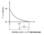
- FIG. 4 is a pressure distribution diagram in the casing downstream portion 24 during use of the extruder.
- “0”, “L”, “S”, “S1” described in FIGS. 1 and 2 correspond to “0”, “L”, “S”, “S1” described in FIG. .
- the casing 4 has a tapered shape, its volume decreases as it approaches the tip of the casing 4, so that the kneaded material pushed out by the screws 2 and 3 becomes consolidated as it approaches the tip of the casing 4. For this reason, the closer the tip of the casing 4 is, the steeper the rise in the pressure in the casing 4 (pressure of the kneaded material).
- “PL” is atmospheric pressure
- “P0” is the pressure at the front end side opening of the casing 4 having the smallest cross-sectional area (pressure of the kneaded material).
- the rotation of the screws 2 and 3 can be achieved by installing the pressure sensor 5 at a location where the difference from the tip pressure of the casing 4 is easily measured.
- the pressure can be measured more appropriately by numerical control. From such a point, it is preferable to measure the pressure inside the casing 4 on the upstream side of the middle (L / 2) between the downstream end 15a of the charging port 15 and the opening on the front end side of the casing 4 (L / 2). Further, the pressure inside the casing 4 in the range S1 portion upstream from the middle between the downstream end 15a of the charging port 15 and the opening on the front end side of the casing 4 is a roller 9 measured by the load sensor 8. Since there is a sufficient difference from the load acting on the pressure 10 (in the embodiment shown in FIG.
- Control method With reference to FIG. 5, a description will be given of the screw rotation speed and the roller rotation speed control method of the extruder 1 with a roller die.
- the above control is performed by the controller 12 (see FIG. 1) as control means.
- the signal from the pressure sensor 5 (5a, 5b) and the signal from the load sensor 8 are taken into the controller 12.
- the controller 12 controls the rotational speeds of the screws 2 and 3 and the rotational speeds of the rollers 9 and 10 based on the acquired signal.
- the controller 12 calculates an average pressure (kneading part average pressure) between the pressure (kneading part pressure) measured by the pressure sensor 5a and the pressure (kneading part pressure) measured by the pressure sensor 5b. Further, the controller 12 calculates an average load (roller average load) of the loads (roller loads) measured by the two load sensors 8.
- an average pressure Kneading part average pressure
- the controller 12 calculates an average load (roller average load) of the loads (roller loads) measured by the two load sensors 8.
- the controller 12 controls the number of rotations of the screws 2 and 3 as follows based on the value of the kneading unit average pressure.
- the controller 12 increases the rotational speed of the screws 2 and 3 when the kneading unit average pressure is lower than a predetermined (allowable) pressure range, and decreases the rotational speed of the screws 2 and 3 when the average pressure is high. Take control. Further, the controller 12 determines that the kneading unit average pressure is within a predetermined (allowable) pressure range, that is, if it is appropriate (appropriate range), the number of rotations of the screws 2 and 3 at that time. Is maintained as it is (step 1 (St1)).
- a low kneading part average pressure means that the state of fullness of the kneaded material in the casing 4 (casing downstream part 24) is low, and the state of fullness of the kneaded material is increased by increasing the rotational speed of the screws 2 and 3. Goes up.
- mixing part average pressure is high means that the filling state of the kneaded material in the casing 4 (casing downstream part 24) is high (too high), and reduces the rotation speed of the screws 2 and 3.
- the filling state of the kneaded product tends to decrease.
- the full state of the kneaded material in the casing 4 (casing downstream portion 24) can be stabilized.
- the kneaded material can be stably kneaded by the screws 2 and 3 in the casing 4 (casing downstream portion 24), and the dispersibility of the kneaded material can be improved.
- the controller 12 controls the number of rotations of the rollers 9 and 10 as follows based on the combination of the kneading unit average pressure value and the roller average load value.
- the roller rotation speed is controlled as follows.
- the controller 12 reduces the rotational speed of the rollers 9 and 10 when the average roller load is lower than a predetermined (allowable) load range, and increases the rotational speed of the rollers 9 and 10 when the average load is high. I do. Further, the controller 12 performs control to increase the number of rotations of the rollers 9 and 10 when the average roller load is within a predetermined (allowable) load range, that is, when it is appropriate (appropriate range). (Step 2_1 (St2_1)).
- the roller rotation speed is controlled as follows.
- the controller 12 reduces the rotational speed of the rollers 9 and 10 when the average roller load is lower than a predetermined (allowable) load range, and increases the rotational speed of the rollers 9 and 10 when the average load is high. I do. Further, the controller 12 performs control to reduce the rotation speed of the rollers 9 and 10 when the average roller load is within a predetermined (allowable) load range, that is, when it is appropriate (appropriate range). (Step 2_3 (St2_3)).
- the roller rotation speed is controlled as follows.
- the controller 12 reduces the rotational speed of the rollers 9 and 10 when the average roller load is lower than a predetermined (allowable) load range, and increases the rotational speed of the rollers 9 and 10 when the average load is high. I do. If the average roller load is within a predetermined (allowable) load range, that is, if it is appropriate (appropriate range), the controller 12 determines the number of rotations of the rollers 9 and 10 at that time. Control to maintain the state is performed (step 2_2 (St2_2)).
- the controller 12 reduces the rotational speed of the rollers 9 and 10 when the roller average load is lower than a predetermined (allowable) load range. Control to increase the rotational speed of the rollers 9 and 10 is performed.
- the controller 12 increases or decreases the rotational speed of the screws 2 and 3 when the average roller load is within a predetermined (allowable) load range, that is, when it is appropriate (appropriate range).
- control is performed to increase, decrease, and maintain the rotation speed of the rollers 9 and 10. More specifically, when the rotational speed of the screws 2 and 3 is increased, the rotational speed of the rollers 9 and 10 is also increased, and when the rotational speed of the screws 2 and 3 is decreased, the rotational speed of the rollers 9 and 10 is increased. If the rotation speed of the screws 2 and 3 is maintained as they are, control is performed to maintain the rotation speeds of the rollers 9 and 10 as they are.
- the pressure of the kneaded material in the upstream side of the roller, that is, the bank portion 11 can be stabilized.
- variation of the quantity of the kneaded material wound between the rollers 9 and 10 can be suppressed, the kneading
- Table 1 summarizes the above-described control of screw rotation speed and roller rotation speed.
- FIG. 6 is a view showing an extruder 102 with a roller die according to the second embodiment of the present invention.
- the same members as those constituting the extruder 1 with a roller die according to the first embodiment are denoted by the same reference numerals (the same applies to a third embodiment to be described later). ).
- the difference between the roller die extruder 102 of the second embodiment and the roller die extruder 1 of the first embodiment is the number of pressure sensors 5 attached to the bottom of the casing 4 (casing downstream portion 24).
- one pressure sensor 5 is arranged in the extrusion direction of the kneaded product (one for the left chamber 4b and one for the right chamber 4c), whereas the second embodiment.
- two pressure sensors 5 are arranged in the extrusion direction of the kneaded product (two in each of the left chamber 4b and the right chamber 4c).
- a total of four pressure sensors 5 are attached to the bottom of the casing 4.
- the pressures measured by the four pressure sensors 5 are used for controlling the screw rotation speed and the roller rotation speed, as described above, the screws 2 and 3 of the present embodiment are connected and rotated at the same rotation speed. Therefore, the average value of the pressure measured by the four pressure sensors 5 is used for controlling the screw rotation speed and the roller rotation speed.
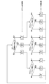
- FIG. 7 is a view showing an extruder 103 with a roller die according to the third embodiment of the present invention.
- a load sensor 8 is attached to the shafts of the rollers 9 and 10.
- the bank part pressure sensor 13 for measuring the pressure of the bank part 11 includes the casing 4 and the roller. 9 and 10.
- the controller 12 determines the average pressure (kneading part average pressure) of the pressure (kneading part pressure) measured by the pressure sensor 5a and the pressure (kneading part pressure) measured by the pressure sensor 5b. ).
- the controller 12 controls the number of rotations of the rollers 9 and 10 based on the combination of the kneading unit average pressure value and the bank unit pressure value measured by the bank unit pressure sensor 13.
- FIG. 8 is a flowchart showing a control flow of the screw rotation speed and the roller rotation speed in the present embodiment.
- the control of the number of rotations of the screws 2 and 3 in the present embodiment is the same as that in the first embodiment.
- the control of the rotation speeds of the rollers 9, 10 that is, a specific example of the control of the roller rotation speed
- Table 2 summarizes the control of the screw rotation speed and the roller rotation speed in this embodiment.
- the pressure on the downstream side of the roller that is, the pressure of the kneaded material in the bank portion 11 can be stabilized.
- variation of the quantity of the kneaded material wound between the rollers 9 and 10 can be suppressed, the kneading
- the pair of left and right screws 2 and 3 of the above-described embodiment are configured to be rotated at the same rotational speed by one driving means.
- the pair of left and right screws 2 and 3 may be configured to be independently rotated by two driving means.
- the rotational speeds of the left and right screws 2 and 3 along the control flow shown in FIG. are controlled separately by the pressure sensors 5 arranged in the respective chambers.
- an average pressure of the pressures measured by the pressure sensors 5 provided in the left and right chambers of the casing 4 is used for the rotation speed control of the rollers 9 and 10.
- Two or more pressure sensors may be attached to the left and right chambers of the casing 4, respectively.
- Three or more pressure sensors may be attached to the casing 4 (casing downstream portion 24) in the extrusion direction of the kneaded product (screw axial direction).
- a screw type extruder having only one screw instead of the pair of left and right screws 2 and 3 may be used.
Landscapes
- Engineering & Computer Science (AREA)
- Mechanical Engineering (AREA)
- Manufacturing & Machinery (AREA)
- Extrusion Moulding Of Plastics Or The Like (AREA)
- Processing And Handling Of Plastics And Other Materials For Molding In General (AREA)
Abstract
This screw extruder is provided with a screw and a casing which accommodates the screw, has a material insertion opening provided on the upstream side in the direction of extrusion of a kneaded material, and has a front end opening on the downstream side. A pressure sensor for measuring pressure within the casing is provided between the downstream end of the insertion opening and the front end opening of the casing, and the rotational speed of the screw is controlled according to pressure measured by the pressure sensor.
Description
本発明は、混練物の押出を行うスクリュ式押出機に関する。
The present invention relates to a screw type extruder for extruding a kneaded product.
自動車用タイヤの製造プロセスにおいて、タイヤの原料であるゴムを混練する混練機の下に設置され、混練機から投入されたゴム(混練物)を連続的に押出しながらシート状に成形する押出成形機が用いられる。この種の押出成形機に関する技術として、例えば下記の特許文献1,2に記載のものがある。
Extruder that is installed under a kneader for kneading rubber, which is a raw material for tires, and forms into a sheet while continuously extruding rubber (kneaded material) fed from the kneader in an automobile tire manufacturing process Is used. As a technique related to this type of extrusion molding machine, for example, there are those described in Patent Documents 1 and 2 below.
特許文献1に記載のシート成形装置は、材料供給部と、材料供給部から供給された弾性材料を一時的に貯留する材料貯留部と、材料貯留部に貯留されている弾性材料を圧延する材料圧延部とを備えている。材料供給部には、2本のスクリュが配置され、スクリュにより弾性材料は材料貯留部を経由して材料圧延部に送られる。材料圧延部には2本のロールが配置され、ロールにより弾性材料はシート状に成形される。
The sheet forming apparatus described in Patent Literature 1 includes a material supply unit, a material storage unit that temporarily stores the elastic material supplied from the material supply unit, and a material that rolls the elastic material stored in the material storage unit. And a rolling section. Two screws are arrange | positioned at a material supply part, and an elastic material is sent to a material rolling part via a material storage part with a screw. Two rolls are disposed in the material rolling portion, and the elastic material is formed into a sheet shape by the rolls.
特許文献2に記載のローラヘッド押出機は、押出機本体と、押出機本体から押し出されてきた練りゴムをシート状に圧延するカレンダロール装置とを備えている。押出機本体とカレンダロール装置との間には、緩衝ロック装置が配置されている。押出機本体とカレンダロール装置との間の圧力(押出機本体のヘッド圧力)を感知する感知装置が、緩衝ロック装置内に設けられている。感知装置により感知された押出機本体のヘッド圧力に応じて、カレンダロールの速度および押出機本体のスクリュ回転数が自動的に制御される。この構成により、熟練した作業者による面倒な手動制御を行う必要なく、常に均一な幅を持つゴムシートを連続的に得ることができる、と特許文献2に記載されている。
The roller head extruder described in Patent Document 2 includes an extruder main body and a calender roll device that rolls the kneaded rubber extruded from the extruder main body into a sheet shape. A buffer lock device is disposed between the extruder main body and the calendar roll device. A sensing device for sensing the pressure between the extruder main body and the calendar roll device (head pressure of the extruder main body) is provided in the buffer lock device. The speed of the calendar roll and the screw rotation speed of the extruder body are automatically controlled in accordance with the head pressure of the extruder body sensed by the sensing device. Patent Document 2 describes that, with this configuration, a rubber sheet having a uniform width can be obtained continuously without the need for troublesome manual control by a skilled worker.
近年、低燃費タイヤの需要が増加している。低燃費タイヤの原料であるゴムにはシリカが高い割合で配合されることが多い。シリカを高い割合で配合したゴム(混練物)は、押出成形機においてシート状に成形しにくいという問題がある。そのため、上流側プロセスの混練機においてだけでなく、押出成形機においてもゴム(混練物)の分散混合性を高めることが望まれる。ゴム(混練物)の分散混合性を高めるには、(1)混練物の押出を行うスクリュ配置部において混練物により多くのエネルギを加えること、(2)混練物の押出を行うスクリュ配置部において混練物の充満状態を安定させること、が必要である。
In recent years, demand for fuel-efficient tires has increased. In many cases, silica, which is a raw material for fuel-efficient tires, is blended in a high proportion. A rubber (kneaded material) containing silica in a high ratio has a problem that it is difficult to form into a sheet form in an extruder. Therefore, it is desired to improve the dispersibility of rubber (kneaded material) not only in the upstream process kneader but also in the extruder. In order to improve the dispersibility of rubber (kneaded material), (1) more energy is applied to the kneaded material in the screw arrangement portion for extruding the kneaded material, and (2) in the screw arrangement portion for extruding the kneaded material. It is necessary to stabilize the full state of the kneaded product.
しかしながら、特許文献1,2には、いずれの文献中にも混練物の分散混合性を高めるための技術に関する記載は無い。なお、特許文献2では、カレンダロールの速度および押出機本体のスクリュ回転数を押出機本体のヘッド圧力に応じて制御しているが、この制御は、押出機本体内の練りゴムの充満状態を安定させるものではない。
However, Patent Documents 1 and 2 do not describe any technique for improving the dispersibility of the kneaded product in any document. In Patent Document 2, the speed of the calender roll and the screw rotation speed of the extruder main body are controlled according to the head pressure of the extruder main body, but this control determines the filling state of the kneaded rubber in the extruder main body. It does not stabilize.
本発明は、上記実情に鑑みてなされたものであり、その目的は、混練物の分散混合性を高めるための上記した(1)、(2)の課題のうちの(2)の課題を解決すること、すなわち、混練物の押出を行うスクリュ配置部において混練物の充満状態を安定させることができる構成のスクリュ式押出機を提供することである。
The present invention has been made in view of the above circumstances, and its object is to solve the problem (2) among the problems (1) and (2) described above for improving the dispersibility of the kneaded product. That is, it is to provide a screw type extruder having a configuration capable of stabilizing the full state of the kneaded material in the screw arrangement portion that performs extrusion of the kneaded material.
本発明に係るスクリュ式押出機は、スクリュと、前記スクリュを収容し、混練物の押出方向上流側に材料の投入口が設けられ下流側に先端側開口を有するケーシングと、を備え、混練物の押出を行うスクリュ式押出機において、 前記投入口の下流側端と前記ケーシングの前記先端側開口との間に、前記ケーシングの内部の圧力を計測する圧力センサが設けられ、前記圧力センサにより計測された圧力に応じて前記スクリュの回転数が制御される、
ことを特徴とする。 A screw-type extruder according to the present invention includes a screw and a casing that accommodates the screw and has a material inlet on the upstream side in the extrusion direction of the kneaded product and a tip side opening on the downstream side. In the screw type extruder for extruding, a pressure sensor for measuring the pressure inside the casing is provided between the downstream end of the charging port and the front end side opening of the casing, and the pressure sensor measures the pressure. The number of rotations of the screw is controlled in accordance with the applied pressure,
It is characterized by that.
この構成によると、上記圧力センサにより計測された圧力に応じてスクリュの回転数を制御することで、混練物の押出を行うスクリュ配置部におけるケーシング内の混練物の充満状態を安定させることができる。これにより、スクリュ配置部においてスクリュによる混練物の安定した混練が可能になり、混練物の分散混合性を高めることができる。
According to this configuration, by controlling the number of rotations of the screw according to the pressure measured by the pressure sensor, it is possible to stabilize the full state of the kneaded material in the casing in the screw arrangement portion that extrudes the kneaded material. . Thereby, stable kneading | mixing of the kneaded material with a screw is attained in a screw arrangement | positioning part, and the dispersibility of a kneaded material can be improved.
また本発明において、前記ケーシングの内壁面は、前記混練物の押出方向に直交する断面において、2つの円が同一面上で一部重なり合った状態の外縁形状となっており、左右一対の前記スクリュが前記ケーシングに収容されており、前記断面において、前記ケーシングの底側中央の頂部から水平方向に延ばした仮想線と左右一対の前記スクリュの回転中心からそれぞれ下方へ延ばした仮想線とで区画された部分の前記ケーシングの内部の圧力が、前記圧力センサにより計測されることが好ましい。
In the present invention, the inner wall surface of the casing has an outer edge shape in which two circles partially overlap on the same plane in a cross section perpendicular to the extrusion direction of the kneaded product, and the pair of left and right screws Is housed in the casing, and in the cross-section, it is partitioned by an imaginary line extending horizontally from the top of the bottom center of the casing and an imaginary line extending downward from the rotation center of the pair of left and right screws. It is preferable that the pressure inside the casing of the part is measured by the pressure sensor.
ケーシング内部のうちの上記区画部分は、圧力が安定し易い部分であり、且つ材料(混練物)に対して混練作用が最も働く部分である。この部分の圧力に基づいてスクリュの回転数を制御することで、ケーシング内の混練物の充満状態をより安定させることができる。また、圧力が安定し易い部分であるということで、この部分での圧力計測は、材料(混練物)の混練度の評価にも適している。
The partition part inside the casing is a part where the pressure is easily stabilized, and the part where the kneading action works most on the material (kneaded material). By controlling the number of rotations of the screw based on the pressure in this portion, the filled state of the kneaded material in the casing can be further stabilized. Moreover, since it is a part where the pressure is easily stabilized, the pressure measurement in this part is also suitable for evaluating the kneading degree of the material (kneaded material).
さらに本発明において、前記ケーシングの左側室および右側室のそれぞれの圧力を計測できるように、前記圧力センサが複数設けられていることが好ましい。
Furthermore, in the present invention, it is preferable that a plurality of the pressure sensors are provided so that the respective pressures in the left chamber and the right chamber of the casing can be measured.
この構成によると、ケーシングの左右の室間で混練物の充満率(圧力)に差がある場合でも、その差に合わせて適切な制御を行うことができる。
According to this configuration, even when there is a difference in the filling rate (pressure) of the kneaded material between the left and right chambers of the casing, appropriate control can be performed according to the difference.
さらに本発明において、前記ケーシングの内部の前記押出方向における複数箇所の圧力を計測できるように、前記圧力センサが複数設けられていることが好ましい。
Further, in the present invention, it is preferable that a plurality of the pressure sensors are provided so that pressures at a plurality of locations in the extrusion direction inside the casing can be measured.
この構成によると、ケーシングから吐出される混練物の圧力を安定させることができる。
According to this configuration, the pressure of the kneaded material discharged from the casing can be stabilized.
さらに本発明において、前記ケーシングの下流側の先方に、前記混練物をシート状に成形する上下一対のローラが配置されており、前記ローラに、該ローラに作用する荷重を計測する荷重センサが設けられており、前記圧力センサにより計測された圧力と前記荷重センサにより計測された荷重との組み合わせで前記ローラの回転数が制御されることが好ましい。
Further, in the present invention, a pair of upper and lower rollers for forming the kneaded material into a sheet shape is disposed on the downstream side of the casing, and a load sensor for measuring a load acting on the rollers is provided on the roller. The number of rotations of the roller is preferably controlled by a combination of the pressure measured by the pressure sensor and the load measured by the load sensor.
この構成によると、ローラ手前の混練物の圧力を安定させることができる。これにより、厚みおよび幅が安定したシートを製造することができる。
According to this configuration, the pressure of the kneaded material before the roller can be stabilized. Thereby, a sheet having a stable thickness and width can be manufactured.
さらに本発明において、前記ケーシングの下流側の先方に、混練物をシート状に成形する上下一対のローラが配置されており、前記ケーシングと前記ローラとの間の部分であるバンク部に、該バンク部の圧力を計測するバンク部圧力センサがさらに設けられており、前記圧力センサにより計測された圧力と前記バンク部圧力センサにより計測された圧力との組み合わせで前記ローラの回転数が制御されることが好ましい。
Furthermore, in the present invention, a pair of upper and lower rollers for forming the kneaded material into a sheet shape is disposed on the downstream side of the casing, and the bank portion, which is a portion between the casing and the roller, A bank part pressure sensor for measuring the pressure of the part is further provided, and the rotational speed of the roller is controlled by a combination of the pressure measured by the pressure sensor and the pressure measured by the bank part pressure sensor. Is preferred.
この構成によると、ローラ手前の混練物の圧力を安定させることができる。これにより、厚みおよび幅が安定したシートを製造することができる。
According to this configuration, the pressure of the kneaded material before the roller can be stabilized. Thereby, a sheet having a stable thickness and width can be manufactured.
さらに本発明において、前記ケーシングは先細り形状であって、前記投入口の下流側端と前記ケーシングの前記先端側開口との間の真中よりも上流側の前記ケーシングの内部の圧力が、前記圧力センサにより計測されることが好ましい。
Further, in the present invention, the casing has a tapered shape, and the pressure inside the casing on the upstream side of the middle between the downstream side end of the charging port and the front end side opening of the casing is the pressure sensor. It is preferable to measure by.
混練物をシート状に成形する上下一対のローラ付きのスクリュ式押出機の場合、本発明では、前記した圧力センサにより計測された圧力に基づくスクリュの回転数制御により、ケーシング内の混練物の充満状態を安定させようとする。また、前記した圧力センサにより計測された圧力と前記した荷重センサにより計測された荷重(または前記したバンク部圧力センサにより計測された圧力)との組み合わせに基づくローラの回転数制御により、シートの厚みおよび幅を安定させようとする。
ここで、ケーシングが先細り形状であると、その先端に近いほどケーシング内の圧力の上昇勾配が急になる。昇圧が大きいところでスクリュの回転エネルギが多く消費されるので、ケーシングの先端圧力との差を測定し易い箇所に前記した圧力センサを設置することで、スクリュの回転数制御により適した圧力の計測を行うことができる。
このような点から、材料投入口の下流側端とケーシングの先端側開口との間の真中よりも上流側のケーシングの内部の圧力を計測することが好ましい。
また、材料投入口の下流側端とケーシングの先端側開口との間の真中よりも上流側のケーシングの内部の圧力は、バンク部の圧力(またはローラに作用する荷重)との差が十分あるので、ローラの回転数制御により適している。 In the case of a screw type extruder with a pair of upper and lower rollers for forming the kneaded material into a sheet, in the present invention, the filling of the kneaded material in the casing is achieved by controlling the rotational speed of the screw based on the pressure measured by the pressure sensor described above. Try to stabilize the state. Further, by controlling the number of rotations of the roller based on the combination of the pressure measured by the pressure sensor and the load measured by the load sensor (or the pressure measured by the bank pressure sensor), the sheet thickness And try to stabilize the width.
Here, if the casing has a tapered shape, the pressure rise gradient in the casing becomes steeper as it approaches the tip. Since a lot of rotational energy of the screw is consumed at a high pressure increase, the pressure sensor described above is installed at a place where the difference from the tip pressure of the casing is easy to measure, so that the pressure can be measured more appropriately by controlling the rotational speed of the screw. It can be carried out.
From such a point, it is preferable to measure the pressure inside the casing upstream from the middle between the downstream end of the material input port and the opening at the front end of the casing.
Further, the pressure inside the casing on the upstream side of the middle between the downstream end of the material input port and the opening on the front end side of the casing is sufficiently different from the pressure of the bank part (or the load acting on the roller). Therefore, it is more suitable for controlling the rotational speed of the roller.
本発明によると、混練物の押出を行うスクリュ配置部において混練物の充満状態を安定させることができるスクリュ式押出機を提供することができる。
According to the present invention, it is possible to provide a screw type extruder that can stabilize the full state of the kneaded material in the screw arrangement portion that extrudes the kneaded material.
以下、本発明を実施するための形態について図面を参照しつつ説明する。以下の実施形態で示すスクリュ式押出機は、ゴムなどの高分子材料の混練物をシート状に押出成形するローラダイ付スクリュ押出機(以下、「ローラダイ付押出機」と呼ぶ)である。なお、本発明のスクリュ式押出機は、高分子材料の混練物を多数の円形孔を有するダイスから押出した後に円筒状のペレットに切断成形するペレタイザと呼ばれる機械にも用いることができる。
Hereinafter, embodiments for carrying out the present invention will be described with reference to the drawings. A screw type extruder shown in the following embodiment is a screw extruder with a roller die (hereinafter referred to as “an extruder with a roller die”) that extrudes a kneaded material of a polymer material such as rubber into a sheet shape. The screw-type extruder of the present invention can also be used in a machine called a pelletizer that extrudes a kneaded material of a polymer material from a die having a large number of circular holes and then cuts it into a cylindrical pellet.
(ローラダイ付押出機の構成)
図1~3を参照しつつ、本発明の第1実施形態に係るローラダイ付押出機1について説明する。ローラダイ付押出機1は、混練物の押出を行う左右一対の計2本のスクリュ2,3と、スクリュ2,3を収容するケーシング4とを有する。ケーシング4の前方には上下一対の計2個のローラ9,10が配置される。ケーシング4とローラ9,10との間の部分は、バンク部11と呼ばれ、スクリュ2,3により押出された混練物は、このバンク部11に溜まる。なお、バンク部11は閉鎖されている。ローラ9,10は、互いに逆方向に回転するように連結されており、図示を省略する1つの駆動手段により同一の回転数(回転速度)で回転させられる。ローラ9,10は、混練物を圧延してシート状に成形するためのものであり、ローラダイと呼ばれている。 (Configuration of extruder with roller die)
A roller die-equippedextruder 1 according to a first embodiment of the present invention will be described with reference to FIGS. The extruder 1 with a roller die has a pair of left and right screws 2 and 3 that extrude the kneaded material, and a casing 4 that accommodates the screws 2 and 3. In front of the casing 4, a total of two rollers 9 and 10 in a pair are arranged. A portion between the casing 4 and the rollers 9 and 10 is referred to as a bank unit 11, and the kneaded material extruded by the screws 2 and 3 accumulates in the bank unit 11. Note that the bank unit 11 is closed. The rollers 9 and 10 are coupled so as to rotate in opposite directions, and are rotated at the same rotational speed (rotational speed) by one driving means (not shown). The rollers 9 and 10 are for rolling the kneaded material into a sheet shape and are called roller dies.
図1~3を参照しつつ、本発明の第1実施形態に係るローラダイ付押出機1について説明する。ローラダイ付押出機1は、混練物の押出を行う左右一対の計2本のスクリュ2,3と、スクリュ2,3を収容するケーシング4とを有する。ケーシング4の前方には上下一対の計2個のローラ9,10が配置される。ケーシング4とローラ9,10との間の部分は、バンク部11と呼ばれ、スクリュ2,3により押出された混練物は、このバンク部11に溜まる。なお、バンク部11は閉鎖されている。ローラ9,10は、互いに逆方向に回転するように連結されており、図示を省略する1つの駆動手段により同一の回転数(回転速度)で回転させられる。ローラ9,10は、混練物を圧延してシート状に成形するためのものであり、ローラダイと呼ばれている。 (Configuration of extruder with roller die)
A roller die-equipped
スクリュ2,3は、それぞれ、軸部6と、軸部6の外周面に設けられた螺旋状のフライト7とを有する。スクリュ2とスクリュ3とは、フライトの捩れ角度が互いに逆であることを除いて同じ形状・寸法のスクリュである。また、スクリュ2,3は、互いに逆方向に回転するように連結されており、図示を省略する1つの駆動手段により同一の回転数で回転させられる。
Each of the screws 2 and 3 has a shaft portion 6 and a spiral flight 7 provided on the outer peripheral surface of the shaft portion 6. The screw 2 and the screw 3 are screws having the same shape and dimensions except that the twisting angles of the flights are opposite to each other. The screws 2 and 3 are coupled so as to rotate in opposite directions, and are rotated at the same rotational speed by a single driving means (not shown).
ケーシング4は、混練物の押出方向上流側から下流側に向けて先細りの形状であって、材料(混練物)の投入口15が上部に設けられたケーシング上流部14と、周囲が壁面で囲われたケーシング下流部24とを有する。投入口15にその上方から供給されたゴムなどの混練物は、互いに逆方向に回転するスクリュ2,3によりバンク部11へ押出され、その後、ローラ9,10の間を通ることでシート状に成形される。
The casing 4 has a tapered shape from the upstream side to the downstream side in the extrusion direction of the kneaded product, and is surrounded by a casing upstream portion 14 provided with a material (kneaded product) inlet 15 at an upper portion and surrounded by a wall surface. And a broken casing downstream portion 24. A kneaded material such as rubber supplied to the charging port 15 from above is extruded into the bank unit 11 by screws 2 and 3 that rotate in opposite directions, and then passes between the rollers 9 and 10 to form a sheet. Molded.
<圧力センサ>
図3に示したように、ケーシング4の内壁面は、混練物の押出方向に直交する断面において、2つの円が同一面上で一部重なり合った状態の外縁形状(メガネ形状)となっており、ケーシング4の左側室4bにスクリュ2が、右側室4cにスクリュ3が収容されている。そして、ケーシング4の底部には、2つの圧力センサ5(5a、5b)が取り付けられている。左側室4b側に圧力センサ5aが取り付けられ、右側室4c側に圧力センサ5bが取り付けられている。圧力センサ5(5a、5b)により、ケーシング4の内部の圧力(混練物の圧力)が計測される。ケーシング4の左右の室の圧力をそれぞれ計測することで、ケーシング4の左右の室間で混練物の充満率(圧力)に差がある場合でも、その差に合わせて後述する制御を適切に行うことができる。 <Pressure sensor>
As shown in FIG. 3, the inner wall surface of thecasing 4 has an outer edge shape (glasses shape) in which two circles partially overlap on the same plane in a cross section perpendicular to the extrusion direction of the kneaded product. The screw 2 is accommodated in the left chamber 4b of the casing 4, and the screw 3 is accommodated in the right chamber 4c. Two pressure sensors 5 (5a, 5b) are attached to the bottom of the casing 4. A pressure sensor 5a is attached to the left chamber 4b side, and a pressure sensor 5b is attached to the right chamber 4c side. The pressure inside the casing 4 (pressure of the kneaded material) is measured by the pressure sensor 5 (5a, 5b). Even if there is a difference in the filling rate (pressure) of the kneaded material between the left and right chambers of the casing 4 by measuring the pressures in the left and right chambers of the casing 4, the control described later is appropriately performed according to the difference. be able to.
図3に示したように、ケーシング4の内壁面は、混練物の押出方向に直交する断面において、2つの円が同一面上で一部重なり合った状態の外縁形状(メガネ形状)となっており、ケーシング4の左側室4bにスクリュ2が、右側室4cにスクリュ3が収容されている。そして、ケーシング4の底部には、2つの圧力センサ5(5a、5b)が取り付けられている。左側室4b側に圧力センサ5aが取り付けられ、右側室4c側に圧力センサ5bが取り付けられている。圧力センサ5(5a、5b)により、ケーシング4の内部の圧力(混練物の圧力)が計測される。ケーシング4の左右の室の圧力をそれぞれ計測することで、ケーシング4の左右の室間で混練物の充満率(圧力)に差がある場合でも、その差に合わせて後述する制御を適切に行うことができる。 <Pressure sensor>
As shown in FIG. 3, the inner wall surface of the
図1,2に示したように、混練物の押出方向においては、圧力センサ5(5a、5b)は、投入口15の下流側端15aとケーシング4の先端側開口との間Sのケーシング4の底部に取り付けられている。換言すれば、圧力センサ5(5a、5b)は、ケーシング4のうちのその下流側部分である、周囲が壁面で囲われたケーシング下流部24の底部に取り付けられている。より好ましくは、本実施形態のように、圧力センサ5(5a、5b)は、投入口15の下流側端15aとケーシング4の先端側開口との間Sであって、且つ、その間Sの真中よりも上流側である範囲S1部分のケーシング4の底部に取り付けられる。
As shown in FIGS. 1 and 2, in the extrusion direction of the kneaded product, the pressure sensor 5 (5 a, 5 b) has a casing 4 in the space S between the downstream end 15 a of the inlet 15 and the front end opening of the casing 4. It is attached to the bottom. In other words, the pressure sensor 5 (5a, 5b) is attached to the bottom portion of the casing downstream portion 24 that is the downstream portion of the casing 4 and is surrounded by a wall surface. More preferably, as in the present embodiment, the pressure sensor 5 (5a, 5b) is located between the downstream end 15a of the inlet 15 and the front end opening of the casing 4, and in the middle of S therebetween. It is attached to the bottom of the casing 4 in the range S1 portion that is upstream of the region.
図3に示したように、ケーシング4の混練物の押出方向に直交する断面視においては、ケーシング4の底側中央の頂部Tから水平方向に延ばした仮想線M1と、スクリュ2,3のそれぞれの回転中心Oから下方へ延ばした仮想線M2,M3とで区画された部分のケーシング4の内部の圧力が計測されるように、圧力センサ5(5a、5b)は、ケーシング4の底部のうちのケーシング中央寄りの部分に取り付けられる。ケーシング4内部のうちの上記区画部分は、圧力が安定し易い部分であり、且つ材料(混練物)に対して混練作用が最も働く部分である。この部分の圧力に基づいてスクリュ2,3の回転数(回転速度)を制御することで、ケーシング4内の混練物の充満状態をより安定させることができる。また、圧力が安定し易い部分であるということで、この部分での圧力計測は、材料(混練物)の混練度の評価にも適している。なお、回転するスクリュ2,3のフライト7と接触しないように圧力センサ5(5a、5b)は、その先端部(圧力検出部)がケーシング4の底側内壁面4aから突出しないように、ケーシング4に取り付けられる。
As shown in FIG. 3, in a cross-sectional view orthogonal to the extrusion direction of the kneaded product of the casing 4, each of the imaginary line M <b> 1 extending in the horizontal direction from the top T at the bottom center of the casing 4 and the screws 2 and 3. The pressure sensor 5 (5a, 5b) includes a bottom portion of the casing 4 so that the pressure inside the casing 4 at a portion partitioned by virtual lines M2, M3 extending downward from the rotation center O of the casing 4 is measured. It is attached to the part near the center of the casing. The partition portion in the casing 4 is a portion where the pressure is easily stabilized and a portion where the kneading action works most on the material (kneaded material). By controlling the rotational speed (rotational speed) of the screws 2 and 3 based on the pressure in this portion, the full state of the kneaded material in the casing 4 can be further stabilized. Moreover, since it is a part where the pressure is easily stabilized, the pressure measurement in this part is also suitable for evaluating the kneading degree of the material (kneaded material). It should be noted that the pressure sensor 5 (5a, 5b) has a casing so that the tip end (pressure detection portion) does not protrude from the bottom inner wall surface 4a of the casing 4 so as not to come into contact with the flight 7 of the rotating screws 2, 3. 4 is attached.
<荷重センサ>
図2に示したように、ケーシング4の前方、即ち、ケーシング4の下流側の先方に配置されたローラ9,10の軸部には、それぞれ荷重センサ8が取り付けられている。荷重センサ8は、例えば歪みゲージで構成される。荷重センサ8は、バンク部11から押し出されてくる混練物の、それぞれのローラ9,10に作用する荷重を計測するセンサである。 <Load sensor>
As shown in FIG. 2,load sensors 8 are attached to the shafts of the rollers 9 and 10 disposed in front of the casing 4, that is, on the downstream side of the casing 4. The load sensor 8 is composed of, for example, a strain gauge. The load sensor 8 is a sensor that measures the load acting on the rollers 9 and 10 of the kneaded material extruded from the bank unit 11.
図2に示したように、ケーシング4の前方、即ち、ケーシング4の下流側の先方に配置されたローラ9,10の軸部には、それぞれ荷重センサ8が取り付けられている。荷重センサ8は、例えば歪みゲージで構成される。荷重センサ8は、バンク部11から押し出されてくる混練物の、それぞれのローラ9,10に作用する荷重を計測するセンサである。 <Load sensor>
As shown in FIG. 2,
図4は、押出機使用中のケーシング下流部24内の圧力分布図である。図1,2中等に記載の「0」、「L」、「S」、「S1」と、図4中に記載の「0」、「L」、「S」、「S1」とは対応する。ケーシング4が先細り形状であると、ケーシング4の先端に近づくほどその容積が小さくなっていくため、スクリュ2,3により押し出されていく混練物は、ケーシング4の先端に近づくにつれて圧密されていく。そのため、ケーシング4の先端に近いほどケーシング4内の圧力(混練物の圧力)の上昇勾配は急になる。「PL」は、大気圧であり、「P0」は、最も断面積が小さいケーシング4の先端側開口における圧力(混練物の圧力)である。
FIG. 4 is a pressure distribution diagram in the casing downstream portion 24 during use of the extruder. “0”, “L”, “S”, “S1” described in FIGS. 1 and 2 correspond to “0”, “L”, “S”, “S1” described in FIG. . If the casing 4 has a tapered shape, its volume decreases as it approaches the tip of the casing 4, so that the kneaded material pushed out by the screws 2 and 3 becomes consolidated as it approaches the tip of the casing 4. For this reason, the closer the tip of the casing 4 is, the steeper the rise in the pressure in the casing 4 (pressure of the kneaded material). “PL” is atmospheric pressure, and “P0” is the pressure at the front end side opening of the casing 4 having the smallest cross-sectional area (pressure of the kneaded material).
昇圧(圧力)が大きいところでスクリュ2,3の回転エネルギが多く消費されるので、ケーシング4の先端圧力との差を測定し易い箇所に圧力センサ5を設置することで、スクリュ2,3の回転数制御により適した圧力の計測を行うことができる。このような点から、投入口15の下流側端15aとケーシング4の先端側開口との間Sの真中(L/2)よりも上流側のケーシング4の内部の圧力を計測することが好ましい。また、投入口15の下流側端15aとケーシング4の先端側開口との間の真中よりも上流側である範囲S1部分のケーシング4の内部の圧力は、荷重センサ8で計測されるローラ9,10に作用する荷重(図7に示す実施形態では、バンク部11の圧力)との差が十分あるので、ローラ9,10の回転数制御により適している。
Since the rotational energy of the screws 2 and 3 is largely consumed when the pressure increase (pressure) is large, the rotation of the screws 2 and 3 can be achieved by installing the pressure sensor 5 at a location where the difference from the tip pressure of the casing 4 is easily measured. The pressure can be measured more appropriately by numerical control. From such a point, it is preferable to measure the pressure inside the casing 4 on the upstream side of the middle (L / 2) between the downstream end 15a of the charging port 15 and the opening on the front end side of the casing 4 (L / 2). Further, the pressure inside the casing 4 in the range S1 portion upstream from the middle between the downstream end 15a of the charging port 15 and the opening on the front end side of the casing 4 is a roller 9 measured by the load sensor 8. Since there is a sufficient difference from the load acting on the pressure 10 (in the embodiment shown in FIG.
(制御方法)
図5を参照しつつ、ローラダイ付押出機1のスクリュ回転数およびローラ回転数の制御方法について説明する。なお、上記制御は、制御手段としてのコントローラ12(図1参照)により行われる。圧力センサ5(5a、5b)からの信号、および荷重センサ8からの信号は、コントローラ12に取り込まれる。コントローラ12は、取り込んだ信号に基づいて、スクリュ2,3の回転数、ローラ9,10の回転数を制御する。 (Control method)
With reference to FIG. 5, a description will be given of the screw rotation speed and the roller rotation speed control method of theextruder 1 with a roller die. The above control is performed by the controller 12 (see FIG. 1) as control means. The signal from the pressure sensor 5 (5a, 5b) and the signal from the load sensor 8 are taken into the controller 12. The controller 12 controls the rotational speeds of the screws 2 and 3 and the rotational speeds of the rollers 9 and 10 based on the acquired signal.
図5を参照しつつ、ローラダイ付押出機1のスクリュ回転数およびローラ回転数の制御方法について説明する。なお、上記制御は、制御手段としてのコントローラ12(図1参照)により行われる。圧力センサ5(5a、5b)からの信号、および荷重センサ8からの信号は、コントローラ12に取り込まれる。コントローラ12は、取り込んだ信号に基づいて、スクリュ2,3の回転数、ローラ9,10の回転数を制御する。 (Control method)
With reference to FIG. 5, a description will be given of the screw rotation speed and the roller rotation speed control method of the
コントローラ12は、圧力センサ5aにより計測された圧力(混練部圧力)と、圧力センサ5bにより計測された圧力(混練部圧力)との平均圧力(混練部平均圧力)を計算する。また、コントローラ12は、2つの荷重センサ8により計測された荷重(ローラ荷重)の平均荷重(ローラ平均荷重)を計算する。ローラダイ付押出機1の混練物押出運転中、各センサ5a,5b,8からの信号は、常時、コントローラ12へ送られている。なお、各センサ5a,5b,8からの信号が、一定の間隔などでコントローラ12へ送られるようになっていてもよい。
The controller 12 calculates an average pressure (kneading part average pressure) between the pressure (kneading part pressure) measured by the pressure sensor 5a and the pressure (kneading part pressure) measured by the pressure sensor 5b. Further, the controller 12 calculates an average load (roller average load) of the loads (roller loads) measured by the two load sensors 8. During the kneaded product extrusion operation of the roller die extruder 1, signals from the sensors 5 a, 5 b and 8 are always sent to the controller 12. The signals from the sensors 5a, 5b, and 8 may be sent to the controller 12 at regular intervals.
<スクリュ回転数の制御>
コントローラ12は、上記混練部平均圧力の値に基づいて、スクリュ2,3の回転数を次のように制御する。 <Control of screw speed>
Thecontroller 12 controls the number of rotations of the screws 2 and 3 as follows based on the value of the kneading unit average pressure.
コントローラ12は、上記混練部平均圧力の値に基づいて、スクリュ2,3の回転数を次のように制御する。 <Control of screw speed>
The
コントローラ12は、上記混練部平均圧力が、所定の(許容される)圧力の範囲よりも低いと、スクリュ2,3の回転数を上昇させ、高いと、スクリュ2,3の回転数を低下させる制御を行う。また、コントローラ12は、上記混練部平均圧力が所定の(許容される)圧力の範囲の中にあると、すなわち、適正(適正範囲)であると、その時点でのスクリュ2,3の回転数をそのまま維持する制御を行う(ステップ1(St1))。
The controller 12 increases the rotational speed of the screws 2 and 3 when the kneading unit average pressure is lower than a predetermined (allowable) pressure range, and decreases the rotational speed of the screws 2 and 3 when the average pressure is high. Take control. Further, the controller 12 determines that the kneading unit average pressure is within a predetermined (allowable) pressure range, that is, if it is appropriate (appropriate range), the number of rotations of the screws 2 and 3 at that time. Is maintained as it is (step 1 (St1)).
混練部平均圧力が低いということは、ケーシング4(ケーシング下流部24)内の混練物の充満状態が低いということであり、スクリュ2,3の回転数を上昇させることで、混練物の充満状態は上昇に向かう。また、混練部平均圧力が高いということは、ケーシング4(ケーシング下流部24)内の混練物の充満状態が高い(高すぎる)ということであり、スクリュ2,3の回転数を低下させることで、混練物の充満状態は低下に向かう。
上記制御により、ケーシング4(ケーシング下流部24)内の混練物の充満状態を安定させることができる。その結果、ケーシング4(ケーシング下流部24)内においてスクリュ2,3による混練物の安定した混練が可能になり、混練物の分散混合性を高めることができる。 A low kneading part average pressure means that the state of fullness of the kneaded material in the casing 4 (casing downstream part 24) is low, and the state of fullness of the kneaded material is increased by increasing the rotational speed of the screws 2 and 3. Goes up. Moreover, that the kneading | mixing part average pressure is high means that the filling state of the kneaded material in the casing 4 (casing downstream part 24) is high (too high), and reduces the rotation speed of the screws 2 and 3. The filling state of the kneaded product tends to decrease.
By the above control, the full state of the kneaded material in the casing 4 (casing downstream portion 24) can be stabilized. As a result, the kneaded material can be stably kneaded by the screws 2 and 3 in the casing 4 (casing downstream portion 24), and the dispersibility of the kneaded material can be improved.
上記制御により、ケーシング4(ケーシング下流部24)内の混練物の充満状態を安定させることができる。その結果、ケーシング4(ケーシング下流部24)内においてスクリュ2,3による混練物の安定した混練が可能になり、混練物の分散混合性を高めることができる。 A low kneading part average pressure means that the state of fullness of the kneaded material in the casing 4 (casing downstream part 24) is low, and the state of fullness of the kneaded material is increased by increasing the rotational speed of the
By the above control, the full state of the kneaded material in the casing 4 (casing downstream portion 24) can be stabilized. As a result, the kneaded material can be stably kneaded by the
<ローラ回転数の制御>
コントローラ12は、上記混練部平均圧力の値と、上記ローラ平均荷重の値との組み合わせに基づいて、ローラ9,10の回転数を次のように制御する。 <Control of roller rotation speed>
Thecontroller 12 controls the number of rotations of the rollers 9 and 10 as follows based on the combination of the kneading unit average pressure value and the roller average load value.
コントローラ12は、上記混練部平均圧力の値と、上記ローラ平均荷重の値との組み合わせに基づいて、ローラ9,10の回転数を次のように制御する。 <Control of roller rotation speed>
The
(1)上記混練部平均圧力が、所定の(許容される)圧力の範囲よりも低い場合、ローラ回転数は次のように制御される。コントローラ12は、上記ローラ平均荷重が、所定の(許容される)荷重の範囲よりも低いと、ローラ9,10の回転数を低下させ、高いと、ローラ9,10の回転数を上昇させる制御を行う。また、コントローラ12は、上記ローラ平均荷重が所定の(許容される)荷重の範囲の中にあると、すなわち、適正(適正範囲)であると、ローラ9,10の回転数を上昇させる制御を行う(ステップ2_1(St2_1))。
(1) When the kneading unit average pressure is lower than a predetermined (allowable) pressure range, the roller rotation speed is controlled as follows. The controller 12 reduces the rotational speed of the rollers 9 and 10 when the average roller load is lower than a predetermined (allowable) load range, and increases the rotational speed of the rollers 9 and 10 when the average load is high. I do. Further, the controller 12 performs control to increase the number of rotations of the rollers 9 and 10 when the average roller load is within a predetermined (allowable) load range, that is, when it is appropriate (appropriate range). (Step 2_1 (St2_1)).
(2)上記混練部平均圧力が、所定の(許容される)圧力の範囲よりも高い場合、ローラ回転数は次のように制御される。コントローラ12は、上記ローラ平均荷重が、所定の(許容される)荷重の範囲よりも低いと、ローラ9,10の回転数を低下させ、高いと、ローラ9,10の回転数を上昇させる制御を行う。また、コントローラ12は、上記ローラ平均荷重が所定の(許容される)荷重の範囲の中にあると、すなわち、適正(適正範囲)であると、ローラ9,10の回転数を低下させる制御を行う(ステップ2_3(St2_3))。
(2) When the kneading unit average pressure is higher than a predetermined (allowable) pressure range, the roller rotation speed is controlled as follows. The controller 12 reduces the rotational speed of the rollers 9 and 10 when the average roller load is lower than a predetermined (allowable) load range, and increases the rotational speed of the rollers 9 and 10 when the average load is high. I do. Further, the controller 12 performs control to reduce the rotation speed of the rollers 9 and 10 when the average roller load is within a predetermined (allowable) load range, that is, when it is appropriate (appropriate range). (Step 2_3 (St2_3)).
(3)上記混練部平均圧力が、所定の(許容される)圧力の範囲の中にある場合、ローラ回転数は次のように制御される。コントローラ12は、上記ローラ平均荷重が、所定の(許容される)荷重の範囲よりも低いと、ローラ9,10の回転数を低下させ、高いと、ローラ9,10の回転数を上昇させる制御を行う。また、コントローラ12は、上記ローラ平均荷重が所定の(許容される)荷重の範囲の中にあると、すなわち、適正(適正範囲)であると、その時点でのローラ9,10の回転数をそのまま維持する制御を行う(ステップ2_2(St2_2))。
(3) When the kneading unit average pressure is within a predetermined (allowable) pressure range, the roller rotation speed is controlled as follows. The controller 12 reduces the rotational speed of the rollers 9 and 10 when the average roller load is lower than a predetermined (allowable) load range, and increases the rotational speed of the rollers 9 and 10 when the average load is high. I do. If the average roller load is within a predetermined (allowable) load range, that is, if it is appropriate (appropriate range), the controller 12 determines the number of rotations of the rollers 9 and 10 at that time. Control to maintain the state is performed (step 2_2 (St2_2)).
上記(1)~(3)の制御を別の表現で記載すると次のようになる。コントローラ12は、上記混練部平均圧力の値に関係なく、上記ローラ平均荷重が、所定の(許容される)荷重の範囲よりも低いと、ローラ9,10の回転数を低下させ、高いと、ローラ9,10の回転数を上昇させる制御を行う。
If the controls (1) to (3) above are described in different expressions, they are as follows. Regardless of the value of the kneading section average pressure, the controller 12 reduces the rotational speed of the rollers 9 and 10 when the roller average load is lower than a predetermined (allowable) load range. Control to increase the rotational speed of the rollers 9 and 10 is performed.
一方、コントローラ12は、上記ローラ平均荷重が所定の(許容される)荷重の範囲の中にあると、すなわち、適正(適正範囲)であると、スクリュ2,3の回転数の上昇、低下、維持、に合わせて、ローラ9,10の回転数を、上昇、低下、維持する制御を行う。より具体的には、スクリュ2,3の回転数を上昇させる場合は、ローラ9,10の回転数も上昇させ、スクリュ2,3の回転数を低下させる場合は、ローラ9,10の回転数も低下させ、スクリュ2,3の回転数をそのまま維持する場合は、ローラ9,10の回転数もそのまま維持する制御を行う。
On the other hand, the controller 12 increases or decreases the rotational speed of the screws 2 and 3 when the average roller load is within a predetermined (allowable) load range, that is, when it is appropriate (appropriate range). In accordance with the maintenance, control is performed to increase, decrease, and maintain the rotation speed of the rollers 9 and 10. More specifically, when the rotational speed of the screws 2 and 3 is increased, the rotational speed of the rollers 9 and 10 is also increased, and when the rotational speed of the screws 2 and 3 is decreased, the rotational speed of the rollers 9 and 10 is increased. If the rotation speed of the screws 2 and 3 is maintained as they are, control is performed to maintain the rotation speeds of the rollers 9 and 10 as they are.
ローラ回転数に関する上記した制御によると、ローラより上流側、すなわちバンク部11における混練物の圧力を安定させることができる。これにより、ローラ9,10間に巻き込まれていく混練物の量の変動を抑制することができ、ケーシング4内で混練物の混練度を向上させることができるとともに、厚みおよび幅が安定したシート50を製造することができる。
According to the above-described control relating to the rotation speed of the roller, the pressure of the kneaded material in the upstream side of the roller, that is, the bank portion 11 can be stabilized. Thereby, the fluctuation | variation of the quantity of the kneaded material wound between the rollers 9 and 10 can be suppressed, the kneading | mixing degree of the kneaded material can be improved in the casing 4, and the thickness and the width | variety were stabilized. 50 can be manufactured.
スクリュ回転数およびローラ回転数の前記した制御を表でまとめると表1のようになる。
Table 1 summarizes the above-described control of screw rotation speed and roller rotation speed.

(第2実施形態)
図6は、本発明の第2実施形態に係るローラダイ付押出機102を示す図である。第2実施形態のローラダイ付押出機102に関し、第1実施形態のローラダイ付押出機1を構成する部材と同一の部材には同一の符号を付している(後述する第3実施形態についても同様)。 (Second Embodiment)
FIG. 6 is a view showing anextruder 102 with a roller die according to the second embodiment of the present invention. Regarding the extruder 102 with a roller die according to the second embodiment, the same members as those constituting the extruder 1 with a roller die according to the first embodiment are denoted by the same reference numerals (the same applies to a third embodiment to be described later). ).
図6は、本発明の第2実施形態に係るローラダイ付押出機102を示す図である。第2実施形態のローラダイ付押出機102に関し、第1実施形態のローラダイ付押出機1を構成する部材と同一の部材には同一の符号を付している(後述する第3実施形態についても同様)。 (Second Embodiment)
FIG. 6 is a view showing an
第2実施形態のローラダイ付押出機102と、第1実施形態のローラダイ付押出機1との相違点は、ケーシング4(ケーシング下流部24)の底部に取り付けた圧力センサ5の数である。第1実施形態のローラダイ付押出機1では、混練物の押出方向において、1つの圧力センサ5を配置しているのに対し(左側室4bおよび右側室4cに1つずつ)、第2実施形態のローラダイ付押出機102では、混練物の押出方向において、2つの圧力センサ5を配置している(左側室4bおよび右側室4cに2つずつ)。
The difference between the roller die extruder 102 of the second embodiment and the roller die extruder 1 of the first embodiment is the number of pressure sensors 5 attached to the bottom of the casing 4 (casing downstream portion 24). In the extruder 1 with a roller die of the first embodiment, one pressure sensor 5 is arranged in the extrusion direction of the kneaded product (one for the left chamber 4b and one for the right chamber 4c), whereas the second embodiment. In the extruder 102 with a roller die, two pressure sensors 5 are arranged in the extrusion direction of the kneaded product (two in each of the left chamber 4b and the right chamber 4c).
具体的には、ローラダイ付押出機102では、左側室4bおよび右側室4cのそれぞれの室に関し、混練物の押出方向において、投入口15の下流側端15aとケーシング4の先端側開口との間Sのケーシング4の底部に、所定の間隔をあけて軸方向に2つの圧力センサ5が取り付けられている。図6には、右側室4cに配置した2つの圧力センサ5bが示されている。このようにして、本実施形態では、ケーシング4の内部の押出方向における複数箇所の圧力を計測できるように、圧力センサ5が複数設けられている。この構成によると、ケーシング4から吐出される混練物の圧力を安定させることができる。これにより、ローラ9,10間に巻き込まれていく混練物の量の変動を抑制することができ、ケーシング4内で混練物の混練度を向上させることができるとともに、厚みおよび幅が安定したシート50を製造することができる。
Specifically, in the extruder 102 with a roller die, with respect to each of the left chamber 4b and the right chamber 4c, between the downstream end 15a of the inlet 15 and the front end opening of the casing 4 in the kneaded product extrusion direction. Two pressure sensors 5 are attached to the bottom of the S casing 4 in the axial direction at a predetermined interval. FIG. 6 shows two pressure sensors 5b arranged in the right chamber 4c. Thus, in this embodiment, a plurality of pressure sensors 5 are provided so that the pressures at a plurality of locations in the extrusion direction inside the casing 4 can be measured. According to this configuration, the pressure of the kneaded material discharged from the casing 4 can be stabilized. Thereby, the fluctuation | variation of the quantity of the kneaded material wound between the rollers 9 and 10 can be suppressed, the kneading | mixing degree of the kneaded material can be improved in the casing 4, and the thickness and the width | variety were stabilized. 50 can be manufactured.
なお、ローラダイ付押出機102では、計4つの圧力センサ5がケーシング4の底部に取り付けられていることになる。なお、4つの圧力センサ5で計測された圧力を、スクリュ回転数およびローラ回転数の制御で用いる場合、前記したように、本実施形態のスクリュ2,3は、連結されて同一回転数で回転させられるものであるので、4つの圧力センサ5で計測された圧力の平均値をスクリュ回転数およびローラ回転数の制御で用いることになる。
In addition, in the extruder 102 with a roller die, a total of four pressure sensors 5 are attached to the bottom of the casing 4. When the pressures measured by the four pressure sensors 5 are used for controlling the screw rotation speed and the roller rotation speed, as described above, the screws 2 and 3 of the present embodiment are connected and rotated at the same rotation speed. Therefore, the average value of the pressure measured by the four pressure sensors 5 is used for controlling the screw rotation speed and the roller rotation speed.
(第3実施形態)
図7は、本発明の第3実施形態に係るローラダイ付押出機103を示す図である。第1実施形態のローラダイ付押出機1では、そのローラ9,10の軸部に荷重センサ8が取り付けられている。第3実施形態のローラダイ付押出機103では、この荷重センサ8に代えて、バンク部11の圧力(バンク部11内の混練物の圧力)を計測するバンク部圧力センサ13が、ケーシング4とローラ9,10との間に設けられている。 (Third embodiment)
FIG. 7 is a view showing anextruder 103 with a roller die according to the third embodiment of the present invention. In the extruder 1 with a roller die of the first embodiment, a load sensor 8 is attached to the shafts of the rollers 9 and 10. In the extruder 103 with a roller die according to the third embodiment, instead of the load sensor 8, the bank part pressure sensor 13 for measuring the pressure of the bank part 11 (pressure of the kneaded material in the bank part 11) includes the casing 4 and the roller. 9 and 10.
図7は、本発明の第3実施形態に係るローラダイ付押出機103を示す図である。第1実施形態のローラダイ付押出機1では、そのローラ9,10の軸部に荷重センサ8が取り付けられている。第3実施形態のローラダイ付押出機103では、この荷重センサ8に代えて、バンク部11の圧力(バンク部11内の混練物の圧力)を計測するバンク部圧力センサ13が、ケーシング4とローラ9,10との間に設けられている。 (Third embodiment)
FIG. 7 is a view showing an
第1実施形態の場合と同様、コントローラ12は、圧力センサ5aにより計測された圧力(混練部圧力)と、圧力センサ5bにより計測された圧力(混練部圧力)との平均圧力(混練部平均圧力)を計算する。
As in the case of the first embodiment, the controller 12 determines the average pressure (kneading part average pressure) of the pressure (kneading part pressure) measured by the pressure sensor 5a and the pressure (kneading part pressure) measured by the pressure sensor 5b. ).
本実施形態では、コントローラ12は、上記混練部平均圧力の値と、バンク部圧力センサ13により計測されたバンク部圧力の値との組み合わせに基づいて、ローラ9,10の回転数を制御する。
In this embodiment, the controller 12 controls the number of rotations of the rollers 9 and 10 based on the combination of the kneading unit average pressure value and the bank unit pressure value measured by the bank unit pressure sensor 13.
図8は、本実施形態におけるスクリュ回転数およびローラ回転数の制御フローを示すフローチャートである。本実施形態におけるスクリュ2,3の回転数の制御については、第1実施形態と同様である。ローラ9,10の回転数の制御の具体例、すなわちローラ回転数の制御の具体例に関しては、図8を参照しつつ第1実施形態の前記「ローラ回転数の制御」の説明における「ローラ平均荷重」を「バンク部圧力」に、ローラ平均荷重に関する記載の「荷重」を「圧力」に、読み替えられたい。なお、本実施形態におけるスクリュ回転数およびローラ回転数の制御をまとめると表2のようになる。
FIG. 8 is a flowchart showing a control flow of the screw rotation speed and the roller rotation speed in the present embodiment. The control of the number of rotations of the screws 2 and 3 in the present embodiment is the same as that in the first embodiment. With regard to a specific example of the control of the rotation speeds of the rollers 9, 10, that is, a specific example of the control of the roller rotation speed, referring to FIG. Please read "Load" as "Bank part pressure" and "Load" in the description about roller average load as "Pressure". Table 2 summarizes the control of the screw rotation speed and the roller rotation speed in this embodiment.
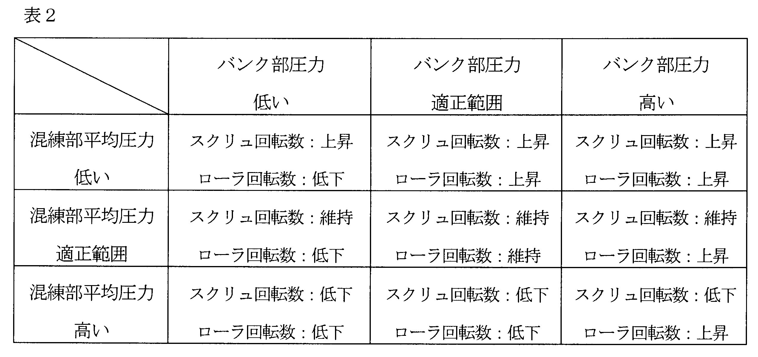
ローラ回転数に関する上記した制御によると、第1実施形態の場合と同様、ローラの下流側の先方、すなわちバンク部11の混練物の圧力を安定させることができる。これにより、ローラ9,10間に巻き込まれていく混練物の量の変動を抑制することができ、ケーシング4内で混練物の混練度を向上させることができるとともに、厚みおよび幅が安定したシート50を製造することができる。
According to the above-described control relating to the rotation speed of the roller, as in the case of the first embodiment, the pressure on the downstream side of the roller, that is, the pressure of the kneaded material in the bank portion 11 can be stabilized. Thereby, the fluctuation | variation of the quantity of the kneaded material wound between the rollers 9 and 10 can be suppressed, the kneading | mixing degree of the kneaded material can be improved in the casing 4, and the thickness and the width | variety were stabilized. 50 can be manufactured.
(変形例)
前記した実施形態の左右一対のスクリュ2,3は、1つの駆動手段により同一の回転数で回転させられる構成とされている。これに代えて、左右一対のスクリュ2,3が、2つの駆動手段により、それぞれ独立に回転させられるように構成されていてもよい。この場合、前記した第1実施形態のようにケーシング4の左右の室のそれぞれに圧力センサ5を設ける場合、例えば、図5に示した制御フローに沿って、左右のスクリュ2,3の回転数をそれぞれの室に配置した圧力センサ5で別々に制御する。ローラ9,10の回転数制御に関しては、ケーシング4の左右の室に設けた圧力センサ5で計測された圧力の例えば平均の圧力をローラ9,10の回転数制御に用いる。 (Modification)
The pair of left and right screws 2 and 3 of the above-described embodiment are configured to be rotated at the same rotational speed by one driving means. Instead of this, the pair of left and right screws 2 and 3 may be configured to be independently rotated by two driving means. In this case, when the pressure sensors 5 are provided in the left and right chambers of the casing 4 as in the first embodiment described above, for example, the rotational speeds of the left and right screws 2 and 3 along the control flow shown in FIG. Are controlled separately by the pressure sensors 5 arranged in the respective chambers. Regarding the rotation speed control of the rollers 9 and 10, for example, an average pressure of the pressures measured by the pressure sensors 5 provided in the left and right chambers of the casing 4 is used for the rotation speed control of the rollers 9 and 10.
前記した実施形態の左右一対のスクリュ2,3は、1つの駆動手段により同一の回転数で回転させられる構成とされている。これに代えて、左右一対のスクリュ2,3が、2つの駆動手段により、それぞれ独立に回転させられるように構成されていてもよい。この場合、前記した第1実施形態のようにケーシング4の左右の室のそれぞれに圧力センサ5を設ける場合、例えば、図5に示した制御フローに沿って、左右のスクリュ2,3の回転数をそれぞれの室に配置した圧力センサ5で別々に制御する。ローラ9,10の回転数制御に関しては、ケーシング4の左右の室に設けた圧力センサ5で計測された圧力の例えば平均の圧力をローラ9,10の回転数制御に用いる。 (Modification)
The pair of left and
ケーシング4(ケーシング下流部24)の内部の圧力を計測する圧力センサ5を、ケーシング4(ケーシング下流部24)の底部ではなく、ケーシング4(ケーシング下流部24)の側部または上部に取り付けてもよい。
Even if the pressure sensor 5 for measuring the pressure inside the casing 4 (casing downstream portion 24) is attached not to the bottom of the casing 4 (casing downstream portion 24) but to the side or top of the casing 4 (casing downstream portion 24). Good.
ケーシング4の左右の室に、それぞれ2つ以上の圧力センサを取り付けてもよい。
Two or more pressure sensors may be attached to the left and right chambers of the casing 4, respectively.
混練物の押出方向(スクリュの軸方向)において、3つ以上の圧力センサをケーシング4(ケーシング下流部24)に取り付けてもよい。
Three or more pressure sensors may be attached to the casing 4 (casing downstream portion 24) in the extrusion direction of the kneaded product (screw axial direction).
左右一対のスクリュ2,3ではなく、スクリュを1本のみ有するスクリュ式押出機であってもよい。
A screw type extruder having only one screw instead of the pair of left and right screws 2 and 3 may be used.
その他に、当業者が想定できる範囲で種々の変更を行える。
In addition, various changes can be made as long as those skilled in the art can assume.
本出願は2016年10月7日出願の日本国特許出願(特願2016-198850)に基づくものであり、その内容はここに参照として取り込まれる。
This application is based on a Japanese patent application filed on October 7, 2016 (Japanese Patent Application No. 2016-198850), the contents of which are incorporated herein by reference.
1:ローラダイ付押出機(スクリュ式押出機)
2、3:スクリュ
4:ケーシング
T:頂部
M1,M2,M3:仮想線
O:回転中心
5:圧力センサ
8:荷重センサ
9、10:ローラ
12:コントローラ
13:バンク部圧力センサ
15:投入口
15a:下流側端 1: Extruder with roller die (screw type extruder)
2, 3: Screw 4: Casing T: Top M1, M2, M3: Virtual line O: Center of rotation 5: Pressure sensor 8:Load sensor 9, 10: Roller 12: Controller 13: Bank part pressure sensor 15: Input port 15a : Downstream end
2、3:スクリュ
4:ケーシング
T:頂部
M1,M2,M3:仮想線
O:回転中心
5:圧力センサ
8:荷重センサ
9、10:ローラ
12:コントローラ
13:バンク部圧力センサ
15:投入口
15a:下流側端 1: Extruder with roller die (screw type extruder)
2, 3: Screw 4: Casing T: Top M1, M2, M3: Virtual line O: Center of rotation 5: Pressure sensor 8:
Claims (10)
- スクリュと、
前記スクリュを収容し、混練物の押出方向上流側に材料の投入口が設けられ下流側に先端側開口を有するケーシングと、
を備え、混練物の押出を行うスクリュ式押出機において、
前記投入口の下流側端と前記ケーシングの前記先端側開口との間に、前記ケーシングの内部の圧力を計測する圧力センサが設けられ、
前記圧力センサにより計測された圧力に応じて前記スクリュの回転数が制御される、
ことを特徴とするスクリュ式押出機。 Screw,
A casing containing the screw, provided with a material inlet on the upstream side in the extrusion direction of the kneaded product, and having a tip side opening on the downstream side;
A screw type extruder for extruding the kneaded product,
Between the downstream end of the charging port and the front end side opening of the casing, a pressure sensor for measuring the pressure inside the casing is provided,
The number of rotations of the screw is controlled according to the pressure measured by the pressure sensor.
A screw type extruder characterized by that. - 請求項1に記載のスクリュ式押出機において、
前記ケーシングの内壁面は、前記混練物の押出方向に直交する断面において、2つの円が同一面上で一部重なり合った状態の外縁形状となっており、
左右一対の前記スクリュが前記ケーシングに収容されており、
前記断面において、前記ケーシングの底側中央の頂部から水平方向に延ばした仮想線と左右一対の前記スクリュの回転中心からそれぞれ下方へ延ばした仮想線とで区画された部分の前記ケーシングの内部の圧力が、前記圧力センサにより計測される、
ことを特徴とするスクリュ式押出機。 In the screw type extruder according to claim 1,
The inner wall surface of the casing has an outer edge shape in a state where two circles partially overlap on the same plane in a cross section perpendicular to the extrusion direction of the kneaded product,
A pair of left and right screws are housed in the casing;
In the cross section, the pressure inside the casing at a portion defined by a virtual line extending in the horizontal direction from the top of the bottom center of the casing and a virtual line extending downward from the rotation center of the pair of left and right screws. Is measured by the pressure sensor,
A screw type extruder characterized by that. - 請求項2に記載のスクリュ式押出機において、
前記ケーシングの左側室および右側室のそれぞれの圧力を計測できるように、前記圧力センサが複数設けられている、
ことを特徴とするスクリュ式押出機。 In the screw type extruder according to claim 2,
A plurality of the pressure sensors are provided so that each pressure of the left chamber and the right chamber of the casing can be measured.
A screw type extruder characterized by that. - 請求項1に記載のスクリュ式押出機において、
前記ケーシングの内部の前記押出方向における複数箇所の圧力を計測できるように、前記圧力センサが複数設けられている、
ことを特徴とするスクリュ式押出機。 In the screw type extruder according to claim 1,
A plurality of the pressure sensors are provided so that the pressures at a plurality of locations in the extrusion direction inside the casing can be measured.
A screw type extruder characterized by that. - 請求項2に記載のスクリュ式押出機において、
前記ケーシングの内部の前記押出方向における複数箇所の圧力を計測できるように、前記圧力センサが複数設けられている、
ことを特徴とするスクリュ式押出機。 In the screw type extruder according to claim 2,
A plurality of the pressure sensors are provided so that the pressures at a plurality of locations in the extrusion direction inside the casing can be measured.
A screw type extruder characterized by that. - 請求項3に記載のスクリュ式押出機において、
前記ケーシングの内部の前記押出方向における複数箇所の圧力を計測できるように、前記圧力センサが複数設けられている、
ことを特徴とするスクリュ式押出機。 In the screw type extruder according to claim 3,
A plurality of the pressure sensors are provided so that the pressures at a plurality of locations in the extrusion direction inside the casing can be measured.
A screw type extruder characterized by that. - 請求項1~6のいずれか1項に記載のスクリュ式押出機において、
前記ケーシングの下流側の先方に、前記混練物をシート状に成形する上下一対のローラが配置されており、
前記ローラに、該ローラに作用する荷重を計測する荷重センサが設けられており、
前記圧力センサにより計測された圧力と前記荷重センサにより計測された荷重との組み合わせで前記ローラの回転数が制御される、
ことを特徴とするスクリュ式押出機。 The screw extruder according to any one of claims 1 to 6,
A pair of upper and lower rollers for forming the kneaded material into a sheet shape is disposed on the downstream side of the casing,
The roller is provided with a load sensor for measuring a load acting on the roller,
The number of rotations of the roller is controlled by a combination of the pressure measured by the pressure sensor and the load measured by the load sensor.
A screw type extruder characterized by that. - 請求項7に記載のスクリュ式押出機において、
前記ケーシングは先細り形状であって、
前記投入口の下流側端と前記ケーシングの前記先端側開口との間の真中よりも上流側の前記ケーシングの内部の圧力が、前記圧力センサにより計測される、
ことを特徴とするスクリュ式押出機。 In the screw type extruder according to claim 7,
The casing has a tapered shape,
The pressure inside the casing upstream of the middle between the downstream end of the charging port and the front end opening of the casing is measured by the pressure sensor;
A screw type extruder characterized by that. - 請求項1~6のいずれかに記載のスクリュ式押出機において、
前記ケーシングの下流側の先方に、混練物をシート状に成形する上下一対のローラが配置されており、
前記ケーシングと前記ローラとの間の部分であるバンク部に、該バンク部の圧力を計測するバンク部圧力センサがさらに設けられており、
前記圧力センサにより計測された圧力と前記バンク部圧力センサにより計測された圧力との組み合わせで前記ローラの回転数が制御される、
ことを特徴とするスクリュ式押出機。 The screw extruder according to any one of claims 1 to 6,
A pair of upper and lower rollers for forming the kneaded material into a sheet shape is disposed on the downstream side of the casing,
A bank part pressure sensor that measures the pressure of the bank part is further provided in the bank part that is a part between the casing and the roller,
The number of rotations of the roller is controlled by a combination of the pressure measured by the pressure sensor and the pressure measured by the bank unit pressure sensor.
A screw type extruder characterized by that. - 請求項9に記載のスクリュ式押出機において、
前記ケーシングは先細り形状であって、
前記投入口の下流側端と前記ケーシングの前記先端側開口との間の真中よりも上流側の前記ケーシングの内部の圧力が、前記圧力センサにより計測される、
ことを特徴とするスクリュ式押出機。 In the screw type extruder according to claim 9,
The casing has a tapered shape,
The pressure inside the casing upstream of the middle between the downstream end of the charging port and the front end opening of the casing is measured by the pressure sensor;
A screw type extruder characterized by that.
Priority Applications (4)
| Application Number | Priority Date | Filing Date | Title |
|---|---|---|---|
| KR1020197009313A KR102150920B1 (en) | 2016-10-07 | 2017-09-08 | Screw extruder |
| EP17858143.5A EP3524404A4 (en) | 2016-10-07 | 2017-09-08 | Screw extruder |
| CN201780062007.8A CN109863011B (en) | 2016-10-07 | 2017-09-08 | Screw extruder |
| US16/337,370 US20200031017A1 (en) | 2016-10-07 | 2017-09-08 | Screw extruder |
Applications Claiming Priority (2)
| Application Number | Priority Date | Filing Date | Title |
|---|---|---|---|
| JP2016198850A JP6662747B2 (en) | 2016-10-07 | 2016-10-07 | Screw type extruder |
| JP2016-198850 | 2016-10-07 |
Publications (1)
| Publication Number | Publication Date |
|---|---|
| WO2018066304A1 true WO2018066304A1 (en) | 2018-04-12 |
Family
ID=61831695
Family Applications (1)
| Application Number | Title | Priority Date | Filing Date |
|---|---|---|---|
| PCT/JP2017/032495 WO2018066304A1 (en) | 2016-10-07 | 2017-09-08 | Screw extruder |
Country Status (7)
| Country | Link |
|---|---|
| US (1) | US20200031017A1 (en) |
| EP (1) | EP3524404A4 (en) |
| JP (1) | JP6662747B2 (en) |
| KR (1) | KR102150920B1 (en) |
| CN (1) | CN109863011B (en) |
| TW (1) | TWI641472B (en) |
| WO (1) | WO2018066304A1 (en) |
Families Citing this family (3)
| Publication number | Priority date | Publication date | Assignee | Title |
|---|---|---|---|---|
| JP6947096B2 (en) | 2018-03-26 | 2021-10-13 | 三菱マテリアル株式会社 | Manufacturing method of insulated superconducting wire |
| JP2020001176A (en) * | 2018-06-25 | 2020-01-09 | 株式会社神戸製鋼所 | Screw-type extruder |
| WO2021165870A1 (en) * | 2020-02-20 | 2021-08-26 | Pomini Rubber & Plastics S.R.L. | Apparatus and method for mixing elastomeric materials |
Citations (7)
| Publication number | Priority date | Publication date | Assignee | Title |
|---|---|---|---|---|
| JPS554575B2 (en) | 1977-10-31 | 1980-01-31 | ||
| JPH04214320A (en) * | 1990-12-12 | 1992-08-05 | Sekisui Chem Co Ltd | Screw extruder |
| JPH0647797A (en) * | 1992-07-29 | 1994-02-22 | Sekisui Chem Co Ltd | Method for controlling extrusion machine |
| JP2006305976A (en) * | 2005-05-02 | 2006-11-09 | Moriyama:Kk | Controlling method of roller head extruder |
| JP2009012463A (en) | 2007-06-06 | 2009-01-22 | Moriyama:Kk | Sheet forming device |
| JP2011500373A (en) * | 2007-10-22 | 2011-01-06 | エレマ エンジニアリング リサイクリング マシネン ウント アンラーゲン ゲゼルシャフト ミット ベシュレンクテル ハフトフング | Method and apparatus for processing synthetic resin materials |
| JP2016198850A (en) | 2015-04-09 | 2016-12-01 | 本田技研工業株式会社 | Autonomous mobile device and autonomous mobile device control method |
Family Cites Families (10)
| Publication number | Priority date | Publication date | Assignee | Title |
|---|---|---|---|---|
| JPS554575A (en) | 1978-06-27 | 1980-01-14 | Noboru Nakatani | Method and apparatus for measuring flow velocity distribution and flow rate by laser doppler method |
| US4428896A (en) * | 1982-08-30 | 1984-01-31 | The General Tire & Rubber Company | Method of producing an extrudate of controlled size and shape from a roller die |
| GB2237239B (en) * | 1989-10-27 | 1993-09-01 | Reifenhaeuser Masch | A process for the production of a ribbon of synthetic thermoplastic material in sheet form |
| JP2871565B2 (en) * | 1995-12-26 | 1999-03-17 | 株式会社神戸製鋼所 | Roller head extruder and control method thereof |
| KR20110099960A (en) * | 2010-03-03 | 2011-09-09 | 조선대학교산학협력단 | The screw and dies of the single screw extruder using the cfd |
| KR20110099957A (en) * | 2010-03-03 | 2011-09-09 | 조선대학교산학협력단 | Single screw polymer extruder |
| WO2014003758A1 (en) * | 2012-06-28 | 2014-01-03 | Dow Global Technologies Llc | Method and apparatus for producing a multi - layer microcapillary film |
| FR3001654B1 (en) * | 2013-02-01 | 2015-06-19 | Michelin & Cie | APPARATUS AND METHOD FOR EXTRUDING ELASTOMER MIXTURE |
| DE102013005199A1 (en) * | 2013-03-25 | 2014-09-25 | Maag Pump Systems Gmbh | Method for controlling a melt-processing plant |
| CN104693819B (en) * | 2015-02-12 | 2019-01-22 | 天津海泰环保科技发展股份有限公司 | A kind of stable storing, ageing-resistant composite S BS particle asphalt modifier and preparation method thereof |
-
2016
- 2016-10-07 JP JP2016198850A patent/JP6662747B2/en not_active Expired - Fee Related
-
2017
- 2017-09-08 CN CN201780062007.8A patent/CN109863011B/en not_active Expired - Fee Related
- 2017-09-08 US US16/337,370 patent/US20200031017A1/en not_active Abandoned
- 2017-09-08 WO PCT/JP2017/032495 patent/WO2018066304A1/en unknown
- 2017-09-08 KR KR1020197009313A patent/KR102150920B1/en active IP Right Grant
- 2017-09-08 EP EP17858143.5A patent/EP3524404A4/en not_active Withdrawn
- 2017-09-21 TW TW106132383A patent/TWI641472B/en not_active IP Right Cessation
Patent Citations (7)
| Publication number | Priority date | Publication date | Assignee | Title |
|---|---|---|---|---|
| JPS554575B2 (en) | 1977-10-31 | 1980-01-31 | ||
| JPH04214320A (en) * | 1990-12-12 | 1992-08-05 | Sekisui Chem Co Ltd | Screw extruder |
| JPH0647797A (en) * | 1992-07-29 | 1994-02-22 | Sekisui Chem Co Ltd | Method for controlling extrusion machine |
| JP2006305976A (en) * | 2005-05-02 | 2006-11-09 | Moriyama:Kk | Controlling method of roller head extruder |
| JP2009012463A (en) | 2007-06-06 | 2009-01-22 | Moriyama:Kk | Sheet forming device |
| JP2011500373A (en) * | 2007-10-22 | 2011-01-06 | エレマ エンジニアリング リサイクリング マシネン ウント アンラーゲン ゲゼルシャフト ミット ベシュレンクテル ハフトフング | Method and apparatus for processing synthetic resin materials |
| JP2016198850A (en) | 2015-04-09 | 2016-12-01 | 本田技研工業株式会社 | Autonomous mobile device and autonomous mobile device control method |
Non-Patent Citations (1)
| Title |
|---|
| See also references of EP3524404A4 |
Also Published As
| Publication number | Publication date |
|---|---|
| KR102150920B1 (en) | 2020-09-02 |
| TWI641472B (en) | 2018-11-21 |
| KR20190046927A (en) | 2019-05-07 |
| JP2018058308A (en) | 2018-04-12 |
| JP6662747B2 (en) | 2020-03-11 |
| EP3524404A1 (en) | 2019-08-14 |
| CN109863011B (en) | 2021-03-12 |
| CN109863011A (en) | 2019-06-07 |
| TW201825258A (en) | 2018-07-16 |
| US20200031017A1 (en) | 2020-01-30 |
| EP3524404A4 (en) | 2020-06-10 |
Similar Documents
| Publication | Publication Date | Title |
|---|---|---|
| WO2018066304A1 (en) | Screw extruder | |
| US4209476A (en) | Method and apparatus for fabrication of extruded articles | |
| TWI729308B (en) | Screw extruder with roller | |
| US7476096B2 (en) | Screw extruder | |
| JPH029616A (en) | Homogenizing performance improving device for cold feeding rubber extruder | |
| WO2019031351A1 (en) | Screw extruder with rollers | |
| CN101898412B (en) | Extrusion control device of weight-loss type measuring control system | |
| JP4365732B2 (en) | Rubber sheet forming device | |
| WO2018142936A1 (en) | Screw-type extruder | |
| US20020146475A1 (en) | Screw extruder and method of controlling the same | |
| US4576563A (en) | Rotary roll-type rubber extruder | |
| TWI671178B (en) | Spiral extruder | |
| JP5484806B2 (en) | Extrusion equipment | |
| EP3797967A1 (en) | Screw-type extruder | |
| JP6392638B2 (en) | Rubber extrusion molding apparatus and method | |
| JP5507528B2 (en) | Feed extruder and feed extrusion method | |
| CN106827460A (en) | A kind of extruder extruding end conveying speed regulation device | |
| CN104870161A (en) | Method for regulating an extrusion device and extrusion device using said method |
Legal Events
| Date | Code | Title | Description |
|---|---|---|---|
| 121 | Ep: the epo has been informed by wipo that ep was designated in this application |
Ref document number: 17858143 Country of ref document: EP Kind code of ref document: A1 |
|
| ENP | Entry into the national phase |
Ref document number: 20197009313 Country of ref document: KR Kind code of ref document: A |
|
| NENP | Non-entry into the national phase |
Ref country code: DE |
|
| ENP | Entry into the national phase |
Ref document number: 2017858143 Country of ref document: EP Effective date: 20190507 |