WO2018061469A1 - Vehicle control device - Google Patents
Vehicle control device Download PDFInfo
- Publication number
- WO2018061469A1 WO2018061469A1 PCT/JP2017/027986 JP2017027986W WO2018061469A1 WO 2018061469 A1 WO2018061469 A1 WO 2018061469A1 JP 2017027986 W JP2017027986 W JP 2017027986W WO 2018061469 A1 WO2018061469 A1 WO 2018061469A1
- Authority
- WO
- WIPO (PCT)
- Prior art keywords
- acceleration
- vehicle
- deceleration
- engine speed
- target
- Prior art date
Links
Images


Classifications
-
- B—PERFORMING OPERATIONS; TRANSPORTING
- B60—VEHICLES IN GENERAL
- B60W—CONJOINT CONTROL OF VEHICLE SUB-UNITS OF DIFFERENT TYPE OR DIFFERENT FUNCTION; CONTROL SYSTEMS SPECIALLY ADAPTED FOR HYBRID VEHICLES; ROAD VEHICLE DRIVE CONTROL SYSTEMS FOR PURPOSES NOT RELATED TO THE CONTROL OF A PARTICULAR SUB-UNIT
- B60W10/00—Conjoint control of vehicle sub-units of different type or different function
- B60W10/04—Conjoint control of vehicle sub-units of different type or different function including control of propulsion units
- B60W10/06—Conjoint control of vehicle sub-units of different type or different function including control of propulsion units including control of combustion engines
-
- B—PERFORMING OPERATIONS; TRANSPORTING
- B60—VEHICLES IN GENERAL
- B60W—CONJOINT CONTROL OF VEHICLE SUB-UNITS OF DIFFERENT TYPE OR DIFFERENT FUNCTION; CONTROL SYSTEMS SPECIALLY ADAPTED FOR HYBRID VEHICLES; ROAD VEHICLE DRIVE CONTROL SYSTEMS FOR PURPOSES NOT RELATED TO THE CONTROL OF A PARTICULAR SUB-UNIT
- B60W10/00—Conjoint control of vehicle sub-units of different type or different function
- B60W10/10—Conjoint control of vehicle sub-units of different type or different function including control of change-speed gearings
-
- B—PERFORMING OPERATIONS; TRANSPORTING
- B60—VEHICLES IN GENERAL
- B60W—CONJOINT CONTROL OF VEHICLE SUB-UNITS OF DIFFERENT TYPE OR DIFFERENT FUNCTION; CONTROL SYSTEMS SPECIALLY ADAPTED FOR HYBRID VEHICLES; ROAD VEHICLE DRIVE CONTROL SYSTEMS FOR PURPOSES NOT RELATED TO THE CONTROL OF A PARTICULAR SUB-UNIT
- B60W10/00—Conjoint control of vehicle sub-units of different type or different function
- B60W10/18—Conjoint control of vehicle sub-units of different type or different function including control of braking systems
-
- B—PERFORMING OPERATIONS; TRANSPORTING
- B60—VEHICLES IN GENERAL
- B60W—CONJOINT CONTROL OF VEHICLE SUB-UNITS OF DIFFERENT TYPE OR DIFFERENT FUNCTION; CONTROL SYSTEMS SPECIALLY ADAPTED FOR HYBRID VEHICLES; ROAD VEHICLE DRIVE CONTROL SYSTEMS FOR PURPOSES NOT RELATED TO THE CONTROL OF A PARTICULAR SUB-UNIT
- B60W30/00—Purposes of road vehicle drive control systems not related to the control of a particular sub-unit, e.g. of systems using conjoint control of vehicle sub-units, or advanced driver assistance systems for ensuring comfort, stability and safety or drive control systems for propelling or retarding the vehicle
- B60W30/18—Propelling the vehicle
- B60W30/18009—Propelling the vehicle related to particular drive situations
- B60W30/18163—Lane change; Overtaking manoeuvres
-
- B—PERFORMING OPERATIONS; TRANSPORTING
- B60—VEHICLES IN GENERAL
- B60W—CONJOINT CONTROL OF VEHICLE SUB-UNITS OF DIFFERENT TYPE OR DIFFERENT FUNCTION; CONTROL SYSTEMS SPECIALLY ADAPTED FOR HYBRID VEHICLES; ROAD VEHICLE DRIVE CONTROL SYSTEMS FOR PURPOSES NOT RELATED TO THE CONTROL OF A PARTICULAR SUB-UNIT
- B60W40/00—Estimation or calculation of non-directly measurable driving parameters for road vehicle drive control systems not related to the control of a particular sub unit, e.g. by using mathematical models
- B60W40/02—Estimation or calculation of non-directly measurable driving parameters for road vehicle drive control systems not related to the control of a particular sub unit, e.g. by using mathematical models related to ambient conditions
- B60W40/04—Traffic conditions
-
- F—MECHANICAL ENGINEERING; LIGHTING; HEATING; WEAPONS; BLASTING
- F02—COMBUSTION ENGINES; HOT-GAS OR COMBUSTION-PRODUCT ENGINE PLANTS
- F02D—CONTROLLING COMBUSTION ENGINES
- F02D29/00—Controlling engines, such controlling being peculiar to the devices driven thereby, the devices being other than parts or accessories essential to engine operation, e.g. controlling of engines by signals external thereto
- F02D29/02—Controlling engines, such controlling being peculiar to the devices driven thereby, the devices being other than parts or accessories essential to engine operation, e.g. controlling of engines by signals external thereto peculiar to engines driving vehicles; peculiar to engines driving variable pitch propellers
-
- F—MECHANICAL ENGINEERING; LIGHTING; HEATING; WEAPONS; BLASTING
- F02—COMBUSTION ENGINES; HOT-GAS OR COMBUSTION-PRODUCT ENGINE PLANTS
- F02D—CONTROLLING COMBUSTION ENGINES
- F02D41/00—Electrical control of supply of combustible mixture or its constituents
- F02D41/02—Circuit arrangements for generating control signals
- F02D41/04—Introducing corrections for particular operating conditions
- F02D41/10—Introducing corrections for particular operating conditions for acceleration
- F02D41/107—Introducing corrections for particular operating conditions for acceleration and deceleration
-
- B—PERFORMING OPERATIONS; TRANSPORTING
- B60—VEHICLES IN GENERAL
- B60W—CONJOINT CONTROL OF VEHICLE SUB-UNITS OF DIFFERENT TYPE OR DIFFERENT FUNCTION; CONTROL SYSTEMS SPECIALLY ADAPTED FOR HYBRID VEHICLES; ROAD VEHICLE DRIVE CONTROL SYSTEMS FOR PURPOSES NOT RELATED TO THE CONTROL OF A PARTICULAR SUB-UNIT
- B60W2540/00—Input parameters relating to occupants
- B60W2540/18—Steering angle
-
- B—PERFORMING OPERATIONS; TRANSPORTING
- B60—VEHICLES IN GENERAL
- B60W—CONJOINT CONTROL OF VEHICLE SUB-UNITS OF DIFFERENT TYPE OR DIFFERENT FUNCTION; CONTROL SYSTEMS SPECIALLY ADAPTED FOR HYBRID VEHICLES; ROAD VEHICLE DRIVE CONTROL SYSTEMS FOR PURPOSES NOT RELATED TO THE CONTROL OF A PARTICULAR SUB-UNIT
- B60W2540/00—Input parameters relating to occupants
- B60W2540/20—Direction indicator values
-
- B—PERFORMING OPERATIONS; TRANSPORTING
- B60—VEHICLES IN GENERAL
- B60W—CONJOINT CONTROL OF VEHICLE SUB-UNITS OF DIFFERENT TYPE OR DIFFERENT FUNCTION; CONTROL SYSTEMS SPECIALLY ADAPTED FOR HYBRID VEHICLES; ROAD VEHICLE DRIVE CONTROL SYSTEMS FOR PURPOSES NOT RELATED TO THE CONTROL OF A PARTICULAR SUB-UNIT
- B60W2552/00—Input parameters relating to infrastructure
- B60W2552/30—Road curve radius
-
- B—PERFORMING OPERATIONS; TRANSPORTING
- B60—VEHICLES IN GENERAL
- B60W—CONJOINT CONTROL OF VEHICLE SUB-UNITS OF DIFFERENT TYPE OR DIFFERENT FUNCTION; CONTROL SYSTEMS SPECIALLY ADAPTED FOR HYBRID VEHICLES; ROAD VEHICLE DRIVE CONTROL SYSTEMS FOR PURPOSES NOT RELATED TO THE CONTROL OF A PARTICULAR SUB-UNIT
- B60W2554/00—Input parameters relating to objects
- B60W2554/80—Spatial relation or speed relative to objects
- B60W2554/801—Lateral distance
-
- B—PERFORMING OPERATIONS; TRANSPORTING
- B60—VEHICLES IN GENERAL
- B60W—CONJOINT CONTROL OF VEHICLE SUB-UNITS OF DIFFERENT TYPE OR DIFFERENT FUNCTION; CONTROL SYSTEMS SPECIALLY ADAPTED FOR HYBRID VEHICLES; ROAD VEHICLE DRIVE CONTROL SYSTEMS FOR PURPOSES NOT RELATED TO THE CONTROL OF A PARTICULAR SUB-UNIT
- B60W2554/00—Input parameters relating to objects
- B60W2554/80—Spatial relation or speed relative to objects
- B60W2554/804—Relative longitudinal speed
-
- B—PERFORMING OPERATIONS; TRANSPORTING
- B60—VEHICLES IN GENERAL
- B60W—CONJOINT CONTROL OF VEHICLE SUB-UNITS OF DIFFERENT TYPE OR DIFFERENT FUNCTION; CONTROL SYSTEMS SPECIALLY ADAPTED FOR HYBRID VEHICLES; ROAD VEHICLE DRIVE CONTROL SYSTEMS FOR PURPOSES NOT RELATED TO THE CONTROL OF A PARTICULAR SUB-UNIT
- B60W2710/00—Output or target parameters relating to a particular sub-units
- B60W2710/06—Combustion engines, Gas turbines
- B60W2710/0644—Engine speed
-
- B—PERFORMING OPERATIONS; TRANSPORTING
- B60—VEHICLES IN GENERAL
- B60W—CONJOINT CONTROL OF VEHICLE SUB-UNITS OF DIFFERENT TYPE OR DIFFERENT FUNCTION; CONTROL SYSTEMS SPECIALLY ADAPTED FOR HYBRID VEHICLES; ROAD VEHICLE DRIVE CONTROL SYSTEMS FOR PURPOSES NOT RELATED TO THE CONTROL OF A PARTICULAR SUB-UNIT
- B60W2710/00—Output or target parameters relating to a particular sub-units
- B60W2710/18—Braking system
-
- F—MECHANICAL ENGINEERING; LIGHTING; HEATING; WEAPONS; BLASTING
- F02—COMBUSTION ENGINES; HOT-GAS OR COMBUSTION-PRODUCT ENGINE PLANTS
- F02D—CONTROLLING COMBUSTION ENGINES
- F02D2200/00—Input parameters for engine control
- F02D2200/02—Input parameters for engine control the parameters being related to the engine
- F02D2200/10—Parameters related to the engine output, e.g. engine torque or engine speed
- F02D2200/101—Engine speed
-
- F—MECHANICAL ENGINEERING; LIGHTING; HEATING; WEAPONS; BLASTING
- F02—COMBUSTION ENGINES; HOT-GAS OR COMBUSTION-PRODUCT ENGINE PLANTS
- F02D—CONTROLLING COMBUSTION ENGINES
- F02D2200/00—Input parameters for engine control
- F02D2200/50—Input parameters for engine control said parameters being related to the vehicle or its components
- F02D2200/501—Vehicle speed
-
- F—MECHANICAL ENGINEERING; LIGHTING; HEATING; WEAPONS; BLASTING
- F02—COMBUSTION ENGINES; HOT-GAS OR COMBUSTION-PRODUCT ENGINE PLANTS
- F02D—CONTROLLING COMBUSTION ENGINES
- F02D2200/00—Input parameters for engine control
- F02D2200/70—Input parameters for engine control said parameters being related to the vehicle exterior
- F02D2200/701—Information about vehicle position, e.g. from navigation system or GPS signal
-
- F—MECHANICAL ENGINEERING; LIGHTING; HEATING; WEAPONS; BLASTING
- F02—COMBUSTION ENGINES; HOT-GAS OR COMBUSTION-PRODUCT ENGINE PLANTS
- F02D—CONTROLLING COMBUSTION ENGINES
- F02D2200/00—Input parameters for engine control
- F02D2200/70—Input parameters for engine control said parameters being related to the vehicle exterior
- F02D2200/702—Road conditions
-
- F—MECHANICAL ENGINEERING; LIGHTING; HEATING; WEAPONS; BLASTING
- F02—COMBUSTION ENGINES; HOT-GAS OR COMBUSTION-PRODUCT ENGINE PLANTS
- F02D—CONTROLLING COMBUSTION ENGINES
- F02D45/00—Electrical control not provided for in groups F02D41/00 - F02D43/00
Definitions
- the present invention relates to a vehicle control device that controls an engine.
- Patent Document 1 As background art in this technical field.
- a lower limit vehicle speed and an upper limit vehicle speed are set.
- the engine is stopped, the clutch between the engine and the wheels is opened, the vehicle is driven by coasting, and the vehicle speed is
- the vehicle speed becomes lower than the vehicle speed, the engine is started and the clutch is engaged to accelerate.
- a technique for controlling the gear ratio so as to drive in the best fuel consumption region of the engine during acceleration control is disclosed.
- Patent Document 2 discloses a technique for determining the possibility of interruption based on information on vehicles in other lanes and, when there is a possibility of interruption, suppressing acceleration so as not to give fear to the driver. Has been.
- JP 2012-47148 A Japanese Patent No. 3736400
- the gear ratio is controlled in order to drive the engine in the best fuel consumption region, and the engine speed is increased.
- the acceleration control is interrupted by interruption or the like, the engine speed is controlled from a high speed to a low speed, and the engine speed fluctuates greatly, resulting in a problem that the drivability of the driver is deteriorated.
- Patent Document 2 there is a problem that, when there is a possibility of occurrence of an interrupt, the acceleration is suppressed in order to suppress the acceleration, and the driver feels uncomfortable.
- the vehicle control device of the present invention is based on the surrounding vehicle information acquisition unit that acquires the surrounding information of the vehicle and the surrounding information from the surrounding vehicle information acquisition unit, and the acceleration possibility of the vehicle.
- an acceleration / deceleration possibility determining unit that determines the possibility of deceleration, and in the automatic acceleration / deceleration control, the acceleration / deceleration possibility determining unit determines whether or not the acceleration / deceleration possibility determining unit may decelerate the target vehicle speed. If it is determined that there is a target engine speed, the target engine speed calculating unit corrects the target engine speed to be smaller than a predetermined target engine speed, and the target engine corrected by the target engine speed calculating unit. And an engine control unit that controls the engine so as to achieve the rotational speed.
- working scene which shows the acceleration possibility judgment in the 1st Embodiment of this invention.
- working scene which shows the deceleration possibility judgment in the 1st Embodiment of this invention.
- the time chart of the target vehicle state control in the 1st Embodiment of this invention. The figure which shows the relationship between the engine efficiency and rotation speed in the 1st Embodiment of this invention.
- the time chart at the time of the deceleration possibility judgment in the 1st Embodiment of this invention. The block diagram which shows the target gear ratio calculation in the 1st Embodiment of this invention.
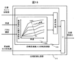
- FIG. 1 is a diagram showing a configuration of a vehicle provided with a vehicle control device in a first embodiment of the present invention.
- an engine 101 is mounted on a vehicle 100, and driving force generated by the engine 101 is transmitted to a wheel 104 connected via a differential mechanism 103 via a transmission 102.
- the vehicle 100 is caused to travel.
- the wheel 104 is provided with a brake mechanism 115, and the braking force changes depending on the amount of pressing of the brake pad in the brake mechanism 115 to adjust the speed of the vehicle 100.
- the transmission 102 includes a torque converter 116, a transmission oil pump 117, a transmission mechanism 118, and a clutch mechanism 119 capable of transmitting and interrupting power from the engine 101 to the wheels 104.
- the torque converter 116 functions to amplify the torque when a rotational difference occurs between the input side and the output side. Therefore, a large driving force can be obtained by increasing the engine speed when rapid acceleration is required.
- the transmission efficiency is increased by engaging a lock-up clutch provided in the torque converter when rapid acceleration is unnecessary. Further, by setting the lock-up clutch to the engaged state during traveling, the engine can be rotated using the force turned from the wheels even when the fuel supply of the engine is stopped (hereinafter referred to as engine braking).
- the oil pump 117 of the transmission is driven via the oil pump drive chain 120.
- the transmission mechanism 118 is not limited to a stepped transmission, and may be a continuously variable transmission in which a belt or a chain and a pulley are combined.
- the clutch mechanism 119 is not limited between the transmission mechanism 118 and the differential mechanism 103, and may be provided between the oil pump drive chain 120 and the transmission mechanism 118.
- the transmission 102 includes a transmission input rotational speed sensor 122 that measures the rotational speed of the input shaft and a transmission output rotational speed sensor 123 that measures the rotational speed of the output shaft.
- the starter motor 105 is assembled as a starting device in the engine 101, and the starter motor 105 is driven by supplying electric power from the battery 108.
- the engine 101 also rotates in conjunction with the rotation of the starter motor 105.
- the engine starter is not limited to the starter motor 105, and may be a motor having functions of a starter motor and a generator.
- An engine speed sensor 121 for detecting the engine speed is attached to the engine 101, and the starter motor 105 is driven to start fuel supply when the engine speed reaches a predetermined value or more. To start the engine.
- a generator 106 is connected to the engine 101 via a drive belt 107.
- the generator 106 can generate electric power by rotating following the rotation of the crankshaft.
- the generator 106 has a mechanism for making the generated voltage variable by controlling the field current, and can also stop the generated output.
- the electric power generated by the generator 106 is supplied to the battery 108 and the in-vehicle electrical component 109.
- the in-vehicle electrical component 109 includes an actuator for operating the engine 101, for example, a fuel supply device, an ignition device, and a controller 111 for controlling them, a lighting device such as a headlight, a brake lamp, and a direction indicator, and a blower fan. And air conditioning equipment such as a heater.
- the controller 111 is detected by an accelerator pedal depression amount detection unit 112 that detects the depression amount of the accelerator pedal, a brake pedal depression amount detection unit 113 that detects the depression amount of the brake pedal, and a vehicle speed detection unit 114 that detects the vehicle speed. Enter information.
- the brake mechanism 115 changes the pressing amount of the brake pad according to the command value from the controller 111 as well as the mechanism for controlling the braking force, with the pressing amount of the brake pad changing according to the brake pedal depression amount of the driver. It may be equipped with a possible electric actuator mechanism.
- the surrounding road information acquisition unit 125 is information on the number of lanes of the vehicle traveling road, information on the curve (distance to the curve, curvature, length of the curve, etc.), information on the intersection (distance to the intersection, temporary stop) Information on the presence / absence of a traffic light, a crossroad, a T-junction, the presence / absence of a traffic light, the current state of the traffic light, the switching timing of the traffic light, etc.).
- the surrounding road information acquisition part 125 may use the result recognized not only by road-vehicle communication or an electronic map but by a camera.
- the surrounding vehicle information acquisition unit 126 only needs to be able to acquire vehicle information (position, speed, acceleration, blinker, steering, etc.) around the vehicle including not only the front-rear direction but also the lateral direction. It may be acquired not only by radar but also by inter-vehicle communication.
- the control method in the present embodiment will be described in detail with reference to FIGS.
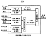
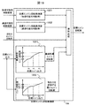
- FIG. 2 shows a control block diagram of the controller 111 of this embodiment.
- the acceleration / deceleration possibility determination unit 201 determines the possibility of acceleration / deceleration of the host vehicle based on the surrounding vehicle information from the surrounding vehicle information acquisition unit 126 and the surrounding road information from the surrounding road information acquisition unit 125. Specifically, the process shown in FIG. 3 is executed. In step S301 of FIG. 3, it is determined whether or not automatic acceleration / deceleration control is being performed. Specifically, the determination is made based on whether or not the driver has operated the steering switch or the like to perform the automatic acceleration / deceleration control.
- the automatic acceleration / deceleration means that the vehicle is automatically accelerated or decelerated by the controller 111 (engine control unit) without the driver's accelerator operation or brake operation.
- the controller 111 detects the acceleration of the vehicle 100, and determines that the vehicle 100 is decelerating when the acceleration of the vehicle 100 is negative.
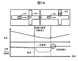
- step S303 the controller 111 determines the possibility of acceleration using at least one of the surrounding road information acquisition unit 125 and the surrounding vehicle information acquisition unit 126. Specifically, as shown in FIG. 4, when the own vehicle 401 is traveling alone at the intersection with a signal (i), the possibility of acceleration is determined according to the color of the traffic light 402 and the distance 403 to the intersection. For example, if the traffic light 402 is blue and the distance 403 from the intersection is less than or equal to the set value, it is determined that there is a possibility of acceleration.
- the controller 111 detects the acceleration of the preceding vehicle based on the signal from the surrounding vehicle information acquisition unit 126.
- the controller 111 has detected that the surrounding vehicle information acquisition unit 126 such as a camera attached to the own vehicle 401 has detected a blinker signal of the preceding vehicle or that the preceding vehicle is being steered. Judgment based on case information.
- the controller 111 determines whether or not the vehicle can pass through based on the own vehicle 401 and the road width.
- step S304 the controller 111 outputs information for switching the vehicle control when there is a possibility of acceleration. Specifically, a digital value (0 when there is no possibility of acceleration, 1 when there is a possibility of acceleration) is output.
- step S305 the controller 111 detects the acceleration of the vehicle 100, and determines that the vehicle is accelerating when the acceleration of the vehicle is positive.
- step S306 the controller 111 determines the possibility of deceleration of the host vehicle 401 using at least one of the surrounding road information acquisition unit 125 and the surrounding vehicle information acquisition unit 126.
- the controller 111 determines the color of the traffic light 402 and the distance 403 between the own vehicle 401 and the intersection.
- the possibility of deceleration of the host vehicle 401 is determined. For example, when the traffic light 402 is blue and the distance 403 between the host vehicle 401 and the intersection is equal to or greater than a set value, the controller 111 determines that the host vehicle 401 may be decelerated. In addition, when the distance 403 between the host vehicle 401 and the intersection is equal to or less than the set value and the traffic light 402 becomes yellow or red, the controller 111 determines that the host vehicle 401 may be decelerated.
- the controller 111 acquires curve information before entering the curve (ii) of the host vehicle 401, an appropriate speed at the time of entering the curve is calculated based on the curvature information. Then, the controller 111 determines that there is a possibility of deceleration of the host vehicle 401 when the speed is larger than the appropriate speed and the distance 501 to the curve is equal to or less than a predetermined value. The controller 111 calculates curvature information based on information from the surrounding road information acquisition unit 125 or the surrounding vehicle information acquisition unit 126.
- the controller 111 may decelerate the host vehicle 401. to decide. Further, when the preceding vehicle interrupts and joins in the own vehicle route due to a right or left turn or the like (iv), the controller 111 determines that the own vehicle 401 may be decelerated. Note that the controller 111 determines that the preceding vehicle has interrupted and joined the own vehicle route based on information from the surrounding road information acquisition unit 125 or the surrounding vehicle information acquisition unit 126.
- the controller 111 detects a request for lane change (v) of the own vehicle 401, and if the preceding vehicle 404 exists at the lane change destination and the speed of the preceding vehicle 404 is smaller than the speed of the own vehicle 401, the controller 111 may be decelerated. Judge that there is.
- the controller 111 determines whether or not there is a winker signal of the own vehicle 401, and when there is a winker signal or when the steering operation amount is a predetermined value or more, to decide.
- the controller 111 determines that there is a possibility of deceleration when detecting a situation in which the parallel running vehicle 502 may be interrupted on the own vehicle traveling path.
- the possibility of interruption of the parallel running vehicle 502 detects that the winker information of the parallel running vehicle 502 and the situation where the parallel running vehicle is steering. Then, the controller 111 determines that there is a possibility of deceleration when the speed of the parallel running vehicle 502 when entering the own vehicle path is slower than the own vehicle speed.
- step S307 the controller 111 outputs information for switching processing when there is a possibility of deceleration. Specifically, a digital value (0 when there is no possibility of deceleration, 1 when there is a possibility of deceleration) is output.
- the constant vehicle speed control required driving force calculation unit calculates the constant vehicle speed control required driving force based on the set vehicle speed, the limit speed, and the current vehicle speed.
- the follow-up control request drive force calculation unit calculates the follow-up control request drive force based on the inter-vehicle distance and relative speed with the preceding vehicle, and the first selection processing unit uses them to calculate the system request drive force. To do.
- the second selection processing unit compares the driver required driving force with the system required driving force to calculate a target driving force.
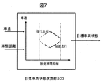
- the target vehicle state calculation unit 203 controls the host vehicle 401 to perform acceleration traveling or coasting traveling as the target vehicle state based on the vehicle speed and the inter-vehicle distance. Specifically, control is performed so as to perform acceleration traveling or coasting traveling so as to be within a preset distance between vehicles.
- the inter-vehicle distance width to be set the inter-vehicle time changed according to the vehicle speed may be used.
- the inter-vehicle distance width to be set may be changed by a driver's operation.
- the inter-vehicle distance specific to the driver learned based on the driver's operation may be used.
- the controller 111 opens the clutch mechanism 119 and stops the fuel supply to the engine 101 (hereinafter referred to as engine stop coasting). Further, if the engine 101 cannot be stopped during coasting traveling, the controller 111 travels in a state where only the clutch mechanism 119 is released (hereinafter referred to as engine idling inertia traveling). Further, when a stronger deceleration is required than when the clutch mechanism 119 is released, the controller 111 selects a method of decelerating by increasing the braking force with the electric brake or a method of decelerating in the engine brake state. Thus, the vehicle is controlled to perform acceleration traveling or coasting so as to be within the inter-vehicle distance range.
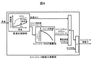
- the engine brake driving force calculation unit of the controller 111 calculates the driving force during engine braking.
- the gear ratio control unit outputs the gear ratio Gc and the engine speed.
- the engine speed of the engine brake varies depending on the vehicle speed, and specifically, the engine speed is targeted when the accelerator operation amount in gear ratio control is 0%.
- the engine brake torque calculation unit outputs this target value as the engine speed during engine braking.
- the relationship between the engine speed and the engine friction at the time of fuel cut is calculated in advance, and the engine speed at the time of engine braking is input.
- the friction torque F ed is calculated and output.
- the engine brake driving force calculation unit takes the product of the gear ratio G c and the final reduction gear ratio G f from the engine friction torque F ed during engine braking, and divides it by the tire radius r so that the engine braking torque applied to the tire
- the driving force is calculated and output.
- FIG. 9 shows the relationship between the target driving force and the target vehicle state when the vehicle speed is in each of acceleration, slow deceleration, and sudden deceleration.
- a thick line indicates the target driving force
- a dotted line indicates an estimated value when the engine brake is applied.
- an estimated value of engine brake driving force when engine braking is applied at the current vehicle speed is calculated.
- the target driving force is larger than the engine braking driving force estimated value by comparing the engine braking driving force estimated value and the target driving force in the slow deceleration section, that is, in FIG.
- the engine brake braking force becomes too large, giving the driver a feeling of deceleration more than necessary.
- the estimated value of the engine brake driving force is 0 or less, which can be referred to as a negative driving force.
- the hatched area is the braking force applied by the friction brake of the automatic electric brake, and is a negative driving force.
- the target driving force becomes smaller than the engine brake driving force estimated value in the sudden deceleration section, that is, in FIG. 9, the dotted line of the engine braking driving force estimated value is lower than the thick line of the target driving force.
- the target vehicle state is switched to the engine brake. That is, control is performed so that the engine brake is applied and a braking force is applied to the vehicle.
- the target engine output calculation unit 204 of the controller 111 in FIG. 2 the target engine output Pt_e is calculated by Expression (1) based on the target driving force Ft and the vehicle speed V.
- P t_e (F t + C d SV 2 + ⁇ Mgcos ⁇ + Mgsin ⁇ ) ⁇ V (1)
- M represents a vehicle weight
- Cd represents an air resistance coefficient
- S represents a front projection area of the vehicle
- V represents a vehicle speed
- ⁇ represents a rolling resistance coefficient
- g represents a gravitational acceleration
- ⁇ represents a road surface gradient.
- the air resistance force C d SV 2 , the dynamic friction force ⁇ Mgcos ⁇ , and the force Mgsin ⁇ that tries to slide down the slope act on the target driving force F t when traveling, so that the target engine output Pt_e It will be as shown in (1).
- the target engine output calculation unit 204 outputs the target engine output Pt_e calculated by the equation (1).
- the target engine output calculation unit 204 outputs the engine output necessary for idling the engine.
- the engine fuel cut calculation unit 206 shown in FIG. Output a signal to perform the cut.
- the clutch release request calculation unit 207 opens the clutch mechanism 119. A signal is output so that the clutch mechanism 119 is engaged at other times.
- the lockup clutch release request calculation unit 208 A signal is output to release the up-clutch, and a lock-up clutch engagement is commanded otherwise.
- the load applied to the wheels is different when the clutch is disengaged and when the engine is braked in engine stop inertia traveling. Therefore, the target brake torque calculation unit 205 calculates the target brake braking force F b [N] according to the powertrain state as shown in Expression (2).
- F b F t + (F ed ⁇ G c ⁇ G f / r)-(C d SV 2 + ⁇ Mgcos ⁇ + Mgsin ⁇ ) (During engine braking) ⁇ ⁇ (2-1) F t- (C d SV 2 + ⁇ Mgcos ⁇ + Mgsin ⁇ ) (during inertia) ⁇ ⁇ (2-2)
- F ed [Nm] represents the engine friction torque when the engine fuel is cut
- G c represents the gear ratio of the gear ratio
- G f represents the gear ratio of the final reduction gear
- r represents the tire radius.
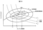
- FIG. 10 shows an engine efficiency curve (solid line) and an iso-output curve (broken line) when the engine speed is plotted on the horizontal axis and the engine torque is plotted on the vertical axis.
- the engine efficiency is generally the highest at the center of the ellipse as shown by the engine efficiency curves (E1, E2, E3), and the efficiency decreases as the distance from the center increases.
- an optimum fuel consumption curve is represented by connecting the points with the highest efficiency in the engine equal output curves (P1, P2, P3). Therefore, in order to operate efficiently for a certain target engine output (P1, P2, P3), it is necessary to control to a certain engine speed (R1, R2, R3).
- the engine has a maximum engine torque (maximum engine torque curve) that can be output depending on the engine speed.
- the target engine output can be realized with respect to a certain target engine output (P1, P2, P3), and the lowest engine speed (R1_min, R2_min, R3_min) is calculated and stored in the storage unit.
- R1_min, R2_min, R3_min the lowest engine speed
- FIG. 12 shows a method for calculating the target engine speed by the target engine speed calculator 209.
- 1201 in FIG. 12 is a diagram showing the relationship between the target engine output and the target engine speed for optimum fuel consumption, and this relational expression 1201 is determined based on FIG.
- reference numeral 1202 in FIG. 12 is a diagram showing the relationship between the target engine output and the minimum engine speed that ensures the equal output of the target engine output, and this relational expression 1202 is determined based on FIG.
- the selection processing unit of the target engine speed calculation unit 209 performs the target engine speed (R1, R2) with respect to the target engine output based on the relational expression 1201 out of the relational expression 1201 and the relational expression 1202. , R3). This makes it possible to drive the engine with optimum fuel consumption.
- the current engine speed, the acceleration possibility determination result, and the deceleration possibility determination result are input to the selection processing unit of the target engine rotation number calculation unit 209.
- the target engine speed calculator 209 calculates the target engine speed based on the relational expression 1202.
- the engine speed is controlled by setting the minimum engine speed to ensure equal output.
- the target engine speed R1, R2, R3
- the target engine speed R1, R2, R3
- the selection processing unit of the target engine speed calculation unit 209 selects the target engine speed based on the relational expression 1202. . Specifically, for example, when it is necessary to accelerate and increase the engine output to P3 in a state where the engine output is P2, there is a possibility of deceleration as described later.
- R3 is obtained.
- the selection processing unit selects R3_min as the target engine speed.
- the engine output is increased from P2 to P3, so that the acceleration performance can be maintained, but the engine speed is suppressed to R3_min smaller than R3. That is, even if there is a subsequent deceleration, the engine speed R3_min is lower than when the engine speed is decreased from R3, so that the driver feels uncomfortable.
- the target engine speed calculation unit 209 determines the current target speed.
- the engine speed is controlled by the number. That is, since the engine speed is controlled with the target speed indicated with no possibility of deceleration, an unnatural increase / decrease in engine speed can be suppressed.
- the selection processing unit determines the optimal fuel efficiency target based on the relational expression 1201.
- the engine speed is output based on the output of the engine speed.
- relational expression 1201 and relational expression 1202 are calculated and stored in the storage unit.
- the target engine speed calculator 209 calculates the target based on the relational expression 1203 shown in FIG. Controls engine speed.
- the horizontal axis indicates the engine speed
- the vertical axis indicates the engine friction torque
- the engine friction torque increases as it goes downward.
- the relational expression 1203 is not shown in the target engine speed calculation unit 209, it corresponds to the relational expression 1202 described above, and this relational expression 1203 is input to the selection processing unit.
- the timing of (1) is a timing in the middle of coasting and dropping the engine speed toward the minimum R1.
- the selection processing unit of the target engine speed calculation unit 209 selects the target engine speed based on the relational expression 1203. For example, when the engine output is P3 and the engine brake is applied to decelerate, if there is no possibility of acceleration, the engine speed is reduced to R1, which is the minimum. However, in this embodiment, since there is a possibility of acceleration thereafter, the selection processing unit selects R2 as the target engine speed.
- the braking force is insufficient only by the engine brake and the engine output cannot be lowered to P1
- the insufficient braking force is controlled to be secured by the brake.
- the necessary braking force is ensured, and even if there is subsequent acceleration, compared with the case where the engine speed is lowered to R1, the subsequent rapid increase in engine speed can be suppressed. Discomfort can be reduced.
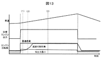
- FIG. 16 is a diagram for explaining a method for setting the target engine speed by the target engine speed calculation unit 209 when the acceleration / deceleration possibility determination unit 201 determines that there is acceleration possibility and when there is no acceleration possibility. It is. As shown in FIG.
- the acceleration / deceleration possibility determination unit 201 causes the surrounding vehicle information from the surrounding vehicle information acquisition unit 126 and the surrounding road information from the surrounding road information acquisition unit 125. If it is determined that there is no possibility of acceleration of the host vehicle, the engine speed is controlled as in the conventional case.
- the host vehicle 401 when the preceding vehicle 404 decelerates, the host vehicle 401 also needs to decelerate, so the engine driving force becomes unnecessary.
- the fuel supply is stopped and the engine brake state is set.
- the target engine speed becomes a speed ratio corresponding to 0% of the accelerator operation amount shown by the speed ratio control unit in FIG. 8, and is controlled to a speed smaller than the speed of the optimum fuel consumption at the time of acceleration.
- the gear ratio is controlled so that the target engine speed for optimum fuel consumption is obtained.
- the optimum fuel consumption engine speed is set to the target engine speed at that time.
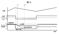
- FIG. 17 shows a situation where an interrupting vehicle 502 enters the own lane from another lane while the own vehicle is accelerating. If it is determined that there is no possibility of acceleration and that there is no possibility of deceleration, gear ratio control is performed so that the target engine speed for optimum fuel consumption is obtained.
- the vehicle must also decelerate or reduce its output, so engine driving force is not required.
- the target engine speed becomes the gear ratio corresponding to 0% of the accelerator operation amount shown by the gear ratio control unit in FIG. Is also controlled to a low rotation speed.
- the engine speed fluctuates greatly, and an uncomfortable feeling due to the engine speed fluctuation occurs.
- the minimum engine speed that guarantees the necessary output during acceleration is expressed by the relational expression 1202.
- the target transmission input rotational speed is calculated by the target transmission input rotational speed calculation 1501, and the target transmission ratio is calculated by dividing by the transmission output rotational speed.
- the target transmission input rotational speed calculation 1501 the result of the target transmission input rotational speed map 1502 corresponding to the target engine rotational speed, the accelerator opening, and the vehicle speed is compared.
- the target transmission input rotational speed map 1502 is set so that the target transmission input rotational speed increases as the accelerator opening increases.
- the larger rotational speed is output as the target transmission input rotational speed.
- the vehicle control device (controller 111) of the present embodiment includes the surrounding vehicle information acquisition unit 126 that acquires the surrounding information of the host vehicle and the surrounding vehicle information acquisition unit 126. And an acceleration / deceleration possibility determination unit 201 that determines the possibility of acceleration or deceleration of the host vehicle based on the surrounding information.
- the vehicle control device is predetermined when the acceleration / deceleration possibility determination unit 201 determines that there is a possibility of deceleration in a state where acceleration is performed so as to achieve the target vehicle speed.
- the target engine speed calculator 209 that corrects the target engine speed so as to be smaller than the target engine speed, and the engine 101 is controlled so that the target engine speed is corrected by the target engine speed calculator 209.
- the vehicle control device (controller 111) has a first acceleration mode and a second acceleration mode having a lower acceleration level than the first acceleration mode, and the target engine speed calculation unit 209 accelerates.
- the target engine speed calculation unit 209 corrects the target engine speed so that the acceleration level is lower than a predetermined acceleration level based on the possibility of deceleration during acceleration.
- the engine control unit sets the target engine speed before correction to the target engine speed. Control the engine.
- the acceleration / deceleration possibility determination unit 201 determines the distance to the intersection, the traffic signal information, the acceleration of the preceding vehicle, the steering angle operation amount of the own vehicle, the winker operation of the own vehicle, the distance to the curve, the curvature of the curve, the parallel running The possibility of deceleration during acceleration is determined based on vehicle position or speed information. Further, the target engine speed calculation unit 209 corrects the target engine speed so that the target engine speed becomes equal to or higher than the minimum engine speed at which a target output in acceleration can be output.
- the engine control unit determines that the target engine speed near the optimum fuel consumption in the engine characteristics.
- the engine 101 is controlled to be a number.
- the vehicle control device (controller 111) performs acceleration / deceleration possibility determination unit 201 in a state where deceleration is performed to achieve the target vehicle speed in the automatic acceleration / deceleration control. If it is determined that there is a possibility of acceleration, the target engine speed calculator 209 that corrects the target engine speed so as to be larger than a predetermined target engine speed, and the target engine speed calculator 209 And an engine control unit that controls the engine 101 so as to achieve the target engine speed corrected by the above.
- the vehicle control device (controller 111) has a first deceleration mode and a second deceleration mode having a lower deceleration level than the first deceleration mode, and the target engine speed calculation unit 209 has a possibility of acceleration during deceleration. And a selection processing unit for selecting the first or second deceleration mode.
- the target engine speed calculation unit 209 corrects the target engine speed so that the deceleration level is higher than a predetermined deceleration level based on the possibility of acceleration during deceleration. Further, the acceleration / deceleration possibility determination unit 201 determines the acceleration possibility during deceleration based on the distance to the intersection, traffic signal information, acceleration of the preceding vehicle, the steering angle operation amount of the own vehicle, the winker operation of the own vehicle, and the road width. to decide.
- FIG. 19 shows a control block diagram of the target engine speed calculation 209 in the second embodiment of the present invention. Specifically, based on the acceleration possibility determination result, the target engine speed 1601 at the time of acceleration possibility determination is calculated, and based on the deceleration possibility determination result, the target engine speed 1602 at the time of deceleration possibility determination is calculated. . In the target engine speed 1601 at the time of determination of acceleration possibility, as shown in FIG. 20, the target engine speed is not increased to the target engine speed of the optimum fuel consumption, based on the determination result of acceleration possibility, but the current engine speed. To maintain. As a result, it is possible to eliminate fluctuations in the engine speed during the acceleration possibility determination, and to reduce the driver's uncomfortable feeling.
- the current engine speed 1602 when determining the possibility of deceleration is not reduced based on the determination result of the deceleration possibility, as shown in FIG. 21, without reducing the target engine speed to the minimum engine speed that guarantees the output. Keep in number. As a result, it is possible to eliminate fluctuations in the engine speed during the determination of the possibility of deceleration, and to reduce the uncomfortable feeling to the driver.
- the target engine speed calculation unit 209 includes a target engine output prediction unit 1901. Specifically, assuming a constant acceleration motion based on the preceding vehicle information (position X p (t), speed V p (t)) at time t, the position of the preceding vehicle at time t + t n The speed is calculated using equations (5) and (6).
- the predicted value D (t) of the inter-vehicle distance and the predicted value of the relative speed V r (t) are expressed by equations (9) (10 ) To calculate.
- the target driving force predicted value F a (t),..., F a (t + t n ) of the own vehicle is calculated using the relationship shown in FIG.
- the target engine output predicted value P e (t),..., P e (t + t n ) is calculated by the equation (11).
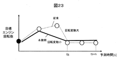
- a predicted value of the target engine speed is calculated using the number relationship 1202. As shown in FIG. 23, by correcting the target value so that a large difference in the target engine speed difference per unit time does not occur in the predicted value of the predicted target engine speed, fluctuations in the engine speed can be suppressed. , Drivability can be improved.
- the engine speed may be held until time t when there is a possibility of deceleration or acceleration, whereby fluctuations in the engine speed can be suppressed, and drivability is improved.
Abstract
In the prior art, when acceleration control has to be halted due to another vehicle cutting in front or the like, control would be implemented to change the rotation speed of the engine from a high rotation speed to a low rotation speed, causing a significant change in engine rotation speed and worsening drivability for the driver. In addition, when there is a possibility of another vehicle cutting in front, acceleration would be suppressed, which would conversely prompt other vehicles to cut in front, disturbing the driver. The present invention addresses this problem by providing a vehicle control device comprising: a target engine rotation speed calculation unit for correcting a target engine rotation speed so as to become less than a predetermined target engine rotation speed when a possibility of deceleration is determined by an acceleration/deceleration possibility determination unit while acceleration is being performed so as to reach a target vehicle speed during automatic acceleration/deceleration control; and an engine control unit for controlling the engine so as to reach the target engine rotation speed corrected by the target engine rotation speed calculation unit.
Description
本発明は、エンジンを制御する車両制御装置に関する。
The present invention relates to a vehicle control device that controls an engine.
本技術分野の背景技術として、特許文献1がある。この公報では、下限車速と上限車速を設定し、車速が上限車速以上になると、エンジンを停止し、さらに、エンジンと車輪との間のクラッチを開放し、惰行により車両を走行させ、車速が下限車速以下になると、エンジンを始動し、クラッチを締結状態にして加速する。また、加速制御時にはエンジンの最良燃費領域で駆動するように変速比を制御する技術が開示されている。
There is Patent Document 1 as background art in this technical field. In this publication, a lower limit vehicle speed and an upper limit vehicle speed are set. When the vehicle speed exceeds the upper limit vehicle speed, the engine is stopped, the clutch between the engine and the wheels is opened, the vehicle is driven by coasting, and the vehicle speed is When the vehicle speed becomes lower than the vehicle speed, the engine is started and the clutch is engaged to accelerate. In addition, a technique for controlling the gear ratio so as to drive in the best fuel consumption region of the engine during acceleration control is disclosed.
特許文献2では、他の車線の車両の情報を基に割り込み可能性を判断し、割り込みの可能性があるときは、ドライバに恐怖感を与えないように加速度を抑制することでする技術が開示されている。
Patent Document 2 discloses a technique for determining the possibility of interruption based on information on vehicles in other lanes and, when there is a possibility of interruption, suppressing acceleration so as not to give fear to the driver. Has been.
上記特許文献1では、エンジンの最良燃費領域で駆動するために変速比を制御し、エンジン回転数を高くする。その際に、割り込みなどにより加速制御が中断すると、エンジン回転数を高い回転数から低い回転数に制御され、エンジン回転数の変動が大きくなり、ドライバの運転性が悪化する問題がある。
In Patent Document 1, the gear ratio is controlled in order to drive the engine in the best fuel consumption region, and the engine speed is increased. At this time, if the acceleration control is interrupted by interruption or the like, the engine speed is controlled from a high speed to a low speed, and the engine speed fluctuates greatly, resulting in a problem that the drivability of the driver is deteriorated.
また、上記特許文献2では、割り込み発生の可能性があるときに、加速度を抑制するため、逆に割り込みを誘発してしまい、ドライバに違和感を与える問題がある。
Also, in the above-mentioned Patent Document 2, there is a problem that, when there is a possibility of occurrence of an interrupt, the acceleration is suppressed in order to suppress the acceleration, and the driver feels uncomfortable.
上記課題を解決するために本発明の車両制御装置は、自車の周辺情報を取得する周辺車両情報取得部と前記周辺車両情報取得部からの周辺情報を基に、自車の加速可能性、又は減速可能性を判断する加減速可能性判断部と、を備え、自動加減速制御において、目標車速となるように加速を行っている状態において、前記加減速可能性判断部により減速可能性があると判断された場合は、あらかじめ定められた目標エンジン回転数よりも小さくなるように目標エンジン回転数を補正する目標エンジン回転数演算部と、前記目標エンジン回転数演算部により補正された目標エンジン回転数となるようにエンジンを制御するエンジン制御部と、を備えた。
In order to solve the above problems, the vehicle control device of the present invention is based on the surrounding vehicle information acquisition unit that acquires the surrounding information of the vehicle and the surrounding information from the surrounding vehicle information acquisition unit, and the acceleration possibility of the vehicle. Or an acceleration / deceleration possibility determining unit that determines the possibility of deceleration, and in the automatic acceleration / deceleration control, the acceleration / deceleration possibility determining unit determines whether or not the acceleration / deceleration possibility determining unit may decelerate the target vehicle speed. If it is determined that there is a target engine speed, the target engine speed calculating unit corrects the target engine speed to be smaller than a predetermined target engine speed, and the target engine corrected by the target engine speed calculating unit. And an engine control unit that controls the engine so as to achieve the rotational speed.
加速時はエンジン効率の高い動作点でエンジンを駆動することで燃費が向上し、加減速可能性があるときは、目標加速度を維持することで運転性能は維持しつつ、エンジン回転数変動によるドライバの運転性悪化を抑制できる。
When accelerating, driving the engine at an operating point with high engine efficiency improves fuel efficiency. When acceleration / deceleration is possible, maintaining the target acceleration and maintaining the driving performance, the driver is driven by fluctuations in engine speed. It is possible to suppress deterioration of drivability.
以下、本発明の実施例について図面を用いて説明する。
Hereinafter, embodiments of the present invention will be described with reference to the drawings.
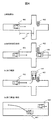
図1は本発明の第1実施例における車両制御装置を備えた車両の構成を示す図である。図1に示すように、車両100には、エンジン101が搭載されており、エンジン101によって発生させた駆動力は変速機102を経て、ディファレンシャル機構103を介して連結された車輪104に伝達されることで車両100を走行させる。また、車両100を減速させるために、車輪104にはブレーキ機構115が備えられ、ブレーキ機構115内のブレーキパッドの押し当て量によって制動力が変化し、車両100の速度を調整する。
FIG. 1 is a diagram showing a configuration of a vehicle provided with a vehicle control device in a first embodiment of the present invention. As shown in FIG. 1, an engine 101 is mounted on a vehicle 100, and driving force generated by the engine 101 is transmitted to a wheel 104 connected via a differential mechanism 103 via a transmission 102. Thus, the vehicle 100 is caused to travel. In addition, in order to decelerate the vehicle 100, the wheel 104 is provided with a brake mechanism 115, and the braking force changes depending on the amount of pressing of the brake pad in the brake mechanism 115 to adjust the speed of the vehicle 100.
変速機102は、トルクコンバータ116と変速機オイルポンプ117と変速機構118とエンジン101からの動力を車輪104に伝達および遮断可能なクラッチ機構119から構成される。トルクコンバータ116は、入力側と出力側に回転差が生じるとトルクの増幅作用が働くため、急加速が必要なときにエンジン回転数を上げることで大きな駆動力が得られる。一方で、回転差が生じているときはトルクの伝達効率が悪いため、急加速が不要なときは、トルクコンバータ内に設けられたロックアップクラッチを締結することで伝達効率を上げている。また、走行中にロックアップクラッチを締結状態にすることで、エンジンの燃料供給を停止しても車輪から回される力を利用してエンジンを回転させることができる(以下、エンジンブレーキという)。
The transmission 102 includes a torque converter 116, a transmission oil pump 117, a transmission mechanism 118, and a clutch mechanism 119 capable of transmitting and interrupting power from the engine 101 to the wheels 104. The torque converter 116 functions to amplify the torque when a rotational difference occurs between the input side and the output side. Therefore, a large driving force can be obtained by increasing the engine speed when rapid acceleration is required. On the other hand, since the torque transmission efficiency is poor when there is a difference in rotation, the transmission efficiency is increased by engaging a lock-up clutch provided in the torque converter when rapid acceleration is unnecessary. Further, by setting the lock-up clutch to the engaged state during traveling, the engine can be rotated using the force turned from the wheels even when the fuel supply of the engine is stopped (hereinafter referred to as engine braking).
また、変速機のオイルポンプ117はオイルポンプ駆動用チェーン120を介して駆動される。ここで、変速機構118は有段変速機に限定されず、ベルトあるいはチェーンとプーリを組み合わせた無段変速機でもよい。クラッチ機構119は変速機構118とディファレンシャル機構103の間に限定されず、オイルポンプ駆動用チェーン120と変速機構118との間に設けてもよい。変速機102には、入力軸の回転数を計測する変速機入力回転数センサ122と、出力軸の回転数を計測する変速機出力回転数センサ123が備えられている。また、エンジンが停止すると、変速機のオイルポンプ117が駆動できないため、変速比を維持する油圧が不足する。そのため、エンジン停止中の変速機の油圧を確保するために、変速機用の電動オイルポンプ124が備えられており、バッテリ108から電力を供給することで必要な油圧を確保している。
Also, the oil pump 117 of the transmission is driven via the oil pump drive chain 120. Here, the transmission mechanism 118 is not limited to a stepped transmission, and may be a continuously variable transmission in which a belt or a chain and a pulley are combined. The clutch mechanism 119 is not limited between the transmission mechanism 118 and the differential mechanism 103, and may be provided between the oil pump drive chain 120 and the transmission mechanism 118. The transmission 102 includes a transmission input rotational speed sensor 122 that measures the rotational speed of the input shaft and a transmission output rotational speed sensor 123 that measures the rotational speed of the output shaft. Further, when the engine is stopped, the oil pump 117 of the transmission cannot be driven, so that the hydraulic pressure for maintaining the gear ratio is insufficient. Therefore, in order to ensure the hydraulic pressure of the transmission when the engine is stopped, an electric oil pump 124 for the transmission is provided, and the necessary hydraulic pressure is ensured by supplying electric power from the battery 108.
エンジン101には始動装置としてスタータモータ105が組みつけられており、バッテリ108から電力を供給することでスタータモータ105を駆動し、スタータモータ105の回転に連動して、エンジン101も回転する。ここで、エンジン始動装置としてはスタータモータ105に限定されず、スタータモータと発電機の機能を有したモータでもよい。また、エンジン101にはエンジンの回転数を検出するエンジン回転数センサ121が取り付けられており、スタータモータ105を駆動させ、エンジン回転数が所定値以上になったときに燃料供給を開始し、点火させることでエンジンを始動する。
The starter motor 105 is assembled as a starting device in the engine 101, and the starter motor 105 is driven by supplying electric power from the battery 108. The engine 101 also rotates in conjunction with the rotation of the starter motor 105. Here, the engine starter is not limited to the starter motor 105, and may be a motor having functions of a starter motor and a generator. An engine speed sensor 121 for detecting the engine speed is attached to the engine 101, and the starter motor 105 is driven to start fuel supply when the engine speed reaches a predetermined value or more. To start the engine.
エンジン101には発電機106が駆動ベルト107介して連結される。発電機106は、クランク軸の回転に従動して回転することで電力を発生させることができる。発電機106は界磁電流を制御することにより、発電電圧を可変にする機構を有しており、発電出力を停止することも可能である。発電機106で発電された電力はバッテリ108と車載電装品109に供給される。車載電装品109には、エンジン101を動作させるためのアクチュエータ、例えば、燃料供給装置、点火装置、それらを制御するコントローラ111も含み、ヘッドライト、ブレーキランプ、方向指示器などの灯火装置、ブロアファン、ヒータなどの空調機器などによって構成される。
A generator 106 is connected to the engine 101 via a drive belt 107. The generator 106 can generate electric power by rotating following the rotation of the crankshaft. The generator 106 has a mechanism for making the generated voltage variable by controlling the field current, and can also stop the generated output. The electric power generated by the generator 106 is supplied to the battery 108 and the in-vehicle electrical component 109. The in-vehicle electrical component 109 includes an actuator for operating the engine 101, for example, a fuel supply device, an ignition device, and a controller 111 for controlling them, a lighting device such as a headlight, a brake lamp, and a direction indicator, and a blower fan. And air conditioning equipment such as a heater.
コントローラ111には、アクセルペダルの踏み込み量を検出するアクセルペダル踏み込み量検出部112、ブレーキペダルの踏み込み量を検出するブレーキペダル踏み込み量検出部113、車両の速度を検出する車速検出部114によって検出した情報を入力する。
The controller 111 is detected by an accelerator pedal depression amount detection unit 112 that detects the depression amount of the accelerator pedal, a brake pedal depression amount detection unit 113 that detects the depression amount of the brake pedal, and a vehicle speed detection unit 114 that detects the vehicle speed. Enter information.
ブレーキ機構115は、運転手のブレーキペダル踏み込み量に応じてブレーキパッドの押し当て量が変化し、制動力を制御する機構だけでなく、コントローラ111からの指令値によって押し当て量を変化させることが可能な電動アクチュータ機構が備わったものでもよい。
The brake mechanism 115 changes the pressing amount of the brake pad according to the command value from the controller 111 as well as the mechanism for controlling the braking force, with the pressing amount of the brake pad changing according to the brake pedal depression amount of the driver. It may be equipped with a possible electric actuator mechanism.
さらに、自車の周辺状況を取得するために、周辺道路情報取得部125と周辺車両情報取得部126の少なくとも1つを有しており、コントローラ111に情報を送信している。ここで、周辺道路情報取得部125は、自車走行道路の車線数や、カーブに関する情報(カーブまでの距離、曲率、カーブの長さなど)や、交差点に関する情報(交差点までの距離、一時停止の有無、十字路、T字路、信号機の有無、信号機の現在の状態、信号機の切り替わりタイミングなど)の情報を取得可能なものであればよい。あるいは周辺道路情報取得部125は、路車間通信や、電子地図のみならず、カメラなどによって認識した結果を使用してもよい。また、周辺車両情報取得部126では、前後方向だけでなく、横方向も含めた自車周辺の車両情報(位置、速度、加速度、ウィンカ、ステアリングなど)を取得可能なものであればよく、カメラやレーダのみならず、車車間通信によって取得してもよい。
本実施例における制御方法について、図2~6を用いて詳細を説明する。図2に本実施例コントローラ111における制御ブロック図を示す。
加減速可能性判断部201では、周辺車両情報取得部126からの周辺車両情報および周辺道路情報取得部125からの周辺道路情報を基に、自車両の加減速の可能性を判断する。具体的には、図3に示す処理を実行する。
図3のステップS301では、自動加減速制御中か否かを判定する。具体的には、ドライバがステアリングスイッチなどで操作し、自動加減速制御を実施する状態にしたか否かで判定する。ここで、自動加減速とはドライバのアクセル操作やブレーキ操作が無い状態でコントローラ111(エンジンコントロールユニット)により自動で車両を加速、又は減速するように制御することを表す。
ステップS302では、コントローラ111は車両100の加速度を検出し、車両100の加速度が負の場合は減速中と判断する。 Furthermore, in order to acquire the surrounding situation of the own vehicle, it has at least one of the surrounding roadinformation acquisition part 125 and the surrounding vehicle information acquisition part 126, and transmits information to the controller 111. Here, the surrounding road information acquisition unit 125 is information on the number of lanes of the vehicle traveling road, information on the curve (distance to the curve, curvature, length of the curve, etc.), information on the intersection (distance to the intersection, temporary stop) Information on the presence / absence of a traffic light, a crossroad, a T-junction, the presence / absence of a traffic light, the current state of the traffic light, the switching timing of the traffic light, etc.). Or the surrounding road information acquisition part 125 may use the result recognized not only by road-vehicle communication or an electronic map but by a camera. The surrounding vehicle information acquisition unit 126 only needs to be able to acquire vehicle information (position, speed, acceleration, blinker, steering, etc.) around the vehicle including not only the front-rear direction but also the lateral direction. It may be acquired not only by radar but also by inter-vehicle communication.
The control method in the present embodiment will be described in detail with reference to FIGS. FIG. 2 shows a control block diagram of the controller 111 of this embodiment.
The acceleration / decelerationpossibility determination unit 201 determines the possibility of acceleration / deceleration of the host vehicle based on the surrounding vehicle information from the surrounding vehicle information acquisition unit 126 and the surrounding road information from the surrounding road information acquisition unit 125. Specifically, the process shown in FIG. 3 is executed.
In step S301 of FIG. 3, it is determined whether or not automatic acceleration / deceleration control is being performed. Specifically, the determination is made based on whether or not the driver has operated the steering switch or the like to perform the automatic acceleration / deceleration control. Here, the automatic acceleration / deceleration means that the vehicle is automatically accelerated or decelerated by the controller 111 (engine control unit) without the driver's accelerator operation or brake operation.
In step S302, the controller 111 detects the acceleration of thevehicle 100, and determines that the vehicle 100 is decelerating when the acceleration of the vehicle 100 is negative.
本実施例における制御方法について、図2~6を用いて詳細を説明する。図2に本実施例コントローラ111における制御ブロック図を示す。
加減速可能性判断部201では、周辺車両情報取得部126からの周辺車両情報および周辺道路情報取得部125からの周辺道路情報を基に、自車両の加減速の可能性を判断する。具体的には、図3に示す処理を実行する。
図3のステップS301では、自動加減速制御中か否かを判定する。具体的には、ドライバがステアリングスイッチなどで操作し、自動加減速制御を実施する状態にしたか否かで判定する。ここで、自動加減速とはドライバのアクセル操作やブレーキ操作が無い状態でコントローラ111(エンジンコントロールユニット)により自動で車両を加速、又は減速するように制御することを表す。
ステップS302では、コントローラ111は車両100の加速度を検出し、車両100の加速度が負の場合は減速中と判断する。 Furthermore, in order to acquire the surrounding situation of the own vehicle, it has at least one of the surrounding road
The control method in the present embodiment will be described in detail with reference to FIGS. FIG. 2 shows a control block diagram of the controller 111 of this embodiment.
The acceleration / deceleration
In step S301 of FIG. 3, it is determined whether or not automatic acceleration / deceleration control is being performed. Specifically, the determination is made based on whether or not the driver has operated the steering switch or the like to perform the automatic acceleration / deceleration control. Here, the automatic acceleration / deceleration means that the vehicle is automatically accelerated or decelerated by the controller 111 (engine control unit) without the driver's accelerator operation or brake operation.
In step S302, the controller 111 detects the acceleration of the
ステップS303では、コントローラ111は周辺道路情報取得部125と周辺車両情報取得部126の少なくとも1つを使用して加速可能性を判断する。具体的には、図4に示すように、信号付き交差点において、自車両401が単独走行中(i)は、信号機402の色と交差点までの距離403に応じて加速可能性を判断する。例えば、信号機402が青色で、交差点との距離403が設定値以下の場合は加速可能性があると判断する。
In step S303, the controller 111 determines the possibility of acceleration using at least one of the surrounding road information acquisition unit 125 and the surrounding vehicle information acquisition unit 126. Specifically, as shown in FIG. 4, when the own vehicle 401 is traveling alone at the intersection with a signal (i), the possibility of acceleration is determined according to the color of the traffic light 402 and the distance 403 to the intersection. For example, if the traffic light 402 is blue and the distance 403 from the intersection is less than or equal to the set value, it is determined that there is a possibility of acceleration.
また、自車両401が先行車404に追従走行中(ii)は信号機402の色が青で、先行車の加速度が正である場合は、加速可能性があると判断する。なお、コントローラ111は周辺車両情報取得部126からの信号に基づいて先行車の加速度を検出する。
Also, when the host vehicle 401 is following the preceding vehicle 404 (ii), if the traffic light 402 is blue and the acceleration of the preceding vehicle is positive, it is determined that there is a possibility of acceleration. The controller 111 detects the acceleration of the preceding vehicle based on the signal from the surrounding vehicle information acquisition unit 126.
また、自車両401が先行車404に追従しており、先行車404が右左折などで自車両401の前方にいなくなった場合で(iii)、かつ、信号機が青色であれば、加速可能性があると判断する。ここで、コントローラ111は、自車両401に取り付けられたカメラなどの周辺車両情報取得部126で、先行車のウィンカ信号を検知した場合や、先行車が操舵している状況であることを検知した場合の情報を基に判断する。
Further, if the own vehicle 401 follows the preceding vehicle 404, the preceding vehicle 404 is not in front of the own vehicle 401 due to a right or left turn or the like (iii), and if the traffic light is blue, acceleration is possible. Judge that there is. Here, the controller 111 has detected that the surrounding vehicle information acquisition unit 126 such as a camera attached to the own vehicle 401 has detected a blinker signal of the preceding vehicle or that the preceding vehicle is being steered. Judgment based on case information.
次に直線路などで、自車両401が先行車404に追従している際に、先行車404の追い抜き要求があることを検知した場合(iv)は、加速可能性があると判断する。追い抜きの要求の検知方法としては自車401のウィンカ信号があるか否かを判断し、ウィンカ信号があり、かつ、自車401がすり抜け可能な場合は、追い抜きを行うものと判断する。ここで、コントローラ111はすり抜け可能の可否を自車401と道路幅などを基に判定する。
Next, when it is detected that there is a request to overtake the preceding vehicle 404 when the host vehicle 401 is following the preceding vehicle 404 on a straight road or the like (iv), it is determined that there is a possibility of acceleration. As a method of detecting the overtaking request, it is determined whether or not there is a winker signal of the own vehicle 401. If there is a winker signal and the own vehicle 401 can pass through, it is determined that the overtaking is performed. Here, the controller 111 determines whether or not the vehicle can pass through based on the own vehicle 401 and the road width.
ステップS304ではコントローラ111は加速可能性があるときに、車両制御を切り替えるための情報を出力する。具体的には、デジタル値(加速可能性がないときは0、加速可能性があるときには1)を出力する。
In step S304, the controller 111 outputs information for switching the vehicle control when there is a possibility of acceleration. Specifically, a digital value (0 when there is no possibility of acceleration, 1 when there is a possibility of acceleration) is output.
ステップS305では、コントローラ111は車両100の加速度を検出し、車両の加速度が正の場合は加速中と判断する。
ステップS306では、コントローラ111は周辺道路情報取得部125と周辺車両情報取得部126の少なくとも1つを使用して自車両401の減速可能性を判断する。 In step S305, the controller 111 detects the acceleration of thevehicle 100, and determines that the vehicle is accelerating when the acceleration of the vehicle is positive.
In step S306, the controller 111 determines the possibility of deceleration of thehost vehicle 401 using at least one of the surrounding road information acquisition unit 125 and the surrounding vehicle information acquisition unit 126.
ステップS306では、コントローラ111は周辺道路情報取得部125と周辺車両情報取得部126の少なくとも1つを使用して自車両401の減速可能性を判断する。 In step S305, the controller 111 detects the acceleration of the
In step S306, the controller 111 determines the possibility of deceleration of the
具体的には、図5に示すように、信号付き交差点において、自車両401が単独走行中(i)は、コントローラ111は信号機402の色と、自車両401と交差点までの距離403に応じて自車両401の減速可能性を判断する。例えば、信号機402が青色で、自車両401と交差点までの距離403が設定値以上の場合に、コントローラ111は自車両401の減速可能性があると判断する。また、自車両401と交差点までの距離403が設定値以下で、信号機402が黄色あるいは赤色になった場合にコントローラ111は自車両401の減速可能性があると判断する。
Specifically, as shown in FIG. 5, when the own vehicle 401 is traveling alone at the intersection with a signal (i), the controller 111 determines the color of the traffic light 402 and the distance 403 between the own vehicle 401 and the intersection. The possibility of deceleration of the host vehicle 401 is determined. For example, when the traffic light 402 is blue and the distance 403 between the host vehicle 401 and the intersection is equal to or greater than a set value, the controller 111 determines that the host vehicle 401 may be decelerated. In addition, when the distance 403 between the host vehicle 401 and the intersection is equal to or less than the set value and the traffic light 402 becomes yellow or red, the controller 111 determines that the host vehicle 401 may be decelerated.
また、コントローラ111が自車両401のカーブ進入前(ii)にカーブ情報を取得した場合、曲率情報を基にカーブ進入時の適切な速度を算出する。そして、コントローラ111は、適切な速度よりも大きく、カーブまでの距離501が所定値以下の場合は自車両401の減速可能性があると判断する。なお、コントローラ111は周辺道路情報取得手段部125、又は周辺車両情報取得手段部126からの情報に基づいて、曲率情報を求める。
In addition, when the controller 111 acquires curve information before entering the curve (ii) of the host vehicle 401, an appropriate speed at the time of entering the curve is calculated based on the curvature information. Then, the controller 111 determines that there is a possibility of deceleration of the host vehicle 401 when the speed is larger than the appropriate speed and the distance 501 to the curve is equal to or less than a predetermined value. The controller 111 calculates curvature information based on information from the surrounding road information acquisition unit 125 or the surrounding vehicle information acquisition unit 126.
また、自車両401が先行車404に追従走行中(iii)において、信号機402の色が青で、先行車の加速度が負である場合は、コントローラ111は自車両401の減速可能性があると判断する。また、右左折などで先行車両が自車経路内に割込み合流した場合は(iv)、コントローラ111は自車両401の減速可能性があると判断する。なお、コントローラ111は周辺道路情報取得手段部125、又は周辺車両情報取得手段部126からの情報に基づいて、先行車両が自車経路内に割込み合流したことを判断する。
When the host vehicle 401 is following the preceding vehicle 404 (iii) and the traffic light 402 is blue and the acceleration of the preceding vehicle is negative, the controller 111 may decelerate the host vehicle 401. to decide. Further, when the preceding vehicle interrupts and joins in the own vehicle route due to a right or left turn or the like (iv), the controller 111 determines that the own vehicle 401 may be decelerated. Note that the controller 111 determines that the preceding vehicle has interrupted and joined the own vehicle route based on information from the surrounding road information acquisition unit 125 or the surrounding vehicle information acquisition unit 126.
また、コントローラ111は自車両401の車線変更(v)の要求を検知し、車線変更先に先行車404が存在し、自車両401の速度よりも先行車404の速度が小さい場合は減速可能性があると判断する。ここで、車線変更要求の検知方法として、コントローラ111は自車401のウィンカ信号があるか否かを判断し、ウィンカ信号があるとき、あるいは、ステアリング操作量が所定値以上のとき、車線変更と判断する。
Further, the controller 111 detects a request for lane change (v) of the own vehicle 401, and if the preceding vehicle 404 exists at the lane change destination and the speed of the preceding vehicle 404 is smaller than the speed of the own vehicle 401, the controller 111 may be decelerated. Judge that there is. Here, as a detection method of the lane change request, the controller 111 determines whether or not there is a winker signal of the own vehicle 401, and when there is a winker signal or when the steering operation amount is a predetermined value or more, to decide.
またコントローラ111は、自車進行経路上に並走車502が割り込んでくる可能性がある状況を検知したときは、減速可能性があると判断する。並走車502の割り込み可能性は、並走車502のウィンカ情報や並走車が操舵している状況であることを検知する。そしてコントローラ111は並走車502の自車経路内への進入時の速度が自車速度よりも遅い場合に、減速可能性があると判断する。
Further, the controller 111 determines that there is a possibility of deceleration when detecting a situation in which the parallel running vehicle 502 may be interrupted on the own vehicle traveling path. The possibility of interruption of the parallel running vehicle 502 detects that the winker information of the parallel running vehicle 502 and the situation where the parallel running vehicle is steering. Then, the controller 111 determines that there is a possibility of deceleration when the speed of the parallel running vehicle 502 when entering the own vehicle path is slower than the own vehicle speed.
ステップS307ではコントローラ111は減速可能性があるときに、処理を切り替えるための情報を出力する。具体的には、デジタル値(減速可能性がないときは0、減速可能性があるときには1)を出力する。
In step S307, the controller 111 outputs information for switching processing when there is a possibility of deceleration. Specifically, a digital value (0 when there is no possibility of deceleration, 1 when there is a possibility of deceleration) is output.
コントローラ111の目標駆動力演算部202では、図6に示すように、ドライバ要求駆動力演算部が車速とアクセルペダル踏み込み量検出部112によって算出されるアクセル開度に応じてドライバが要求する駆動力を算出する。また、定車速制御要求駆動力演算部は、設定車速や制限速度と現在の車速を基に、定車速制御要求駆動力を算出する。さらに、追従制御要求駆動力演算部は先行車との車間距離や相対速度を基に、追従制御要求駆動力を算出し、第一選択処理部は、それらを用いて、システム要求駆動力を算出する。
最後に、第二選択処理部は、ドライバ要求駆動力とシステム要求駆動力を比較し、目標駆動力を算出する。 In the target drivingforce calculation unit 202 of the controller 111, as shown in FIG. 6, the driving force requested by the driver according to the accelerator opening calculated by the driver requested driving force calculation unit by the vehicle speed and the accelerator pedal depression amount detection unit 112. Is calculated. The constant vehicle speed control required driving force calculation unit calculates the constant vehicle speed control required driving force based on the set vehicle speed, the limit speed, and the current vehicle speed. Furthermore, the follow-up control request drive force calculation unit calculates the follow-up control request drive force based on the inter-vehicle distance and relative speed with the preceding vehicle, and the first selection processing unit uses them to calculate the system request drive force. To do.
Finally, the second selection processing unit compares the driver required driving force with the system required driving force to calculate a target driving force.
最後に、第二選択処理部は、ドライバ要求駆動力とシステム要求駆動力を比較し、目標駆動力を算出する。 In the target driving
Finally, the second selection processing unit compares the driver required driving force with the system required driving force to calculate a target driving force.
目標車両状態演算部203では、図7に示すように、車速と車間距離に基づいて、目標車両状態として、加速走行、又は惰行走行を行うように自車両401を制御する。具体的には、あらかじめ設定した車間距離幅内に収まるように加速走行、又は惰行走行を行うように制御する。ここで、設定する車間距離幅は、車速に応じて変化させた車間時間を用いてもよい。また、設定する車間距離幅はドライバの操作によって変更できるようにしてもよい。さらに、ドライバの操作に基づいて学習したドライバ固有の車間距離にしてもよい。
As shown in FIG. 7, the target vehicle state calculation unit 203 controls the host vehicle 401 to perform acceleration traveling or coasting traveling as the target vehicle state based on the vehicle speed and the inter-vehicle distance. Specifically, control is performed so as to perform acceleration traveling or coasting traveling so as to be within a preset distance between vehicles. Here, as the inter-vehicle distance width to be set, the inter-vehicle time changed according to the vehicle speed may be used. The inter-vehicle distance width to be set may be changed by a driver's operation. Furthermore, the inter-vehicle distance specific to the driver learned based on the driver's operation may be used.
コントローラ111は惰行走行中において、エンジン101が停止可能な状態であれば、クラッチ機構119を開放し、エンジン101への燃料供給を停止した状態(以下、エンジン停止惰性走行)で走行させる。またコントローラ111は惰行走行中においてエンジン101が停止不可能な状態であれば、クラッチ機構119のみを開放した状態(以下、エンジンアイドリング惰性走行)で走行させる。さらに、コントローラ111はクラッチ機構119を開放したときよりも、強い減速度が必要な場合は、電動ブレーキにより制動力を増加させて減速する方法、あるいはエンジンブレーキ状態にして減速する方法を選択することで、車間距離幅内に収まるように加速走行、又は惰行走行を行うように制御する。
If the engine 101 can be stopped during coasting, the controller 111 opens the clutch mechanism 119 and stops the fuel supply to the engine 101 (hereinafter referred to as engine stop coasting). Further, if the engine 101 cannot be stopped during coasting traveling, the controller 111 travels in a state where only the clutch mechanism 119 is released (hereinafter referred to as engine idling inertia traveling). Further, when a stronger deceleration is required than when the clutch mechanism 119 is released, the controller 111 selects a method of decelerating by increasing the braking force with the electric brake or a method of decelerating in the engine brake state. Thus, the vehicle is controlled to perform acceleration traveling or coasting so as to be within the inter-vehicle distance range.
目標駆動力を基に、目標車両状態を制御する手法について説明する。
まず、図8に示すようにコントローラ111のエンジンブレーキ駆動力演算部では、エンジンブレーキ時の駆動力を算出する。変速比制御部は変速比Gcとエンジン回転数を出力する。エンジンブレーキは車速に応じてエンジン回転数が異なり、具体的には変速比制御におけるアクセル操作量が0%のときのエンジン回転数を目標としている。エンジンブレーキトルク演算部では、この目標値をエンジンブレーキ時のエンジン回転数として出力する。次に、燃料カットを行った際のエンジン回転数とエンジンフリクションの関係をあらかじめ算出しておき、エンジンブレーキ時のエンジン回転数を入力することで、エンジンブレーキトルク演算部では、エンジンブレーキ時のエンジンフリクショントルクFedを算出し出力する。エンジンブレーキ駆動力演算部では、エンジンブレーキ時のエンジンフリクショントルクFedに、変速比Gcおよび最終減速機ギア比Gfの積を取り、タイヤ半径rで割ることで、タイヤにかかるエンジンブレーキ時の駆動力を算出して出力する。
図9は車速が加速、緩減速、急減速のそれぞれの状態において、目標駆動力と目標車両状態との関係を示す。ここでは加速を行った後の緩減速の状態から、急減速に変わった状態について説明する。駆動力に関して太線は目標駆動力を示しており、これに対して点線はエンジンブレーキをかけた場合の推定値を示している。本実施例では、現在の車速においてエンジンブレーキをかけた場合のエンジンブレーキ駆動力推定値を計算している。緩減速の区間で、エンジンブレーキ駆動力推定値と目標駆動力とを比較して目標駆動力がエンジンブレーキ駆動力推定値よりも大きい場合、つまり、図9において、目標駆動力の太線よりもエンジンブレーキ駆動力推定値の点線が下側にある状態では、エンジンブレーキをかけると、エンジンブレーキ制動力が大き過ぎてしまい、必要以上の減速感をドライバに与えることになる。 A method for controlling the target vehicle state based on the target driving force will be described.
First, as shown in FIG. 8, the engine brake driving force calculation unit of the controller 111 calculates the driving force during engine braking. The gear ratio control unit outputs the gear ratio Gc and the engine speed. The engine speed of the engine brake varies depending on the vehicle speed, and specifically, the engine speed is targeted when the accelerator operation amount in gear ratio control is 0%. The engine brake torque calculation unit outputs this target value as the engine speed during engine braking. Next, the relationship between the engine speed and the engine friction at the time of fuel cut is calculated in advance, and the engine speed at the time of engine braking is input. The friction torque F ed is calculated and output. The engine brake driving force calculation unit takes the product of the gear ratio G c and the final reduction gear ratio G f from the engine friction torque F ed during engine braking, and divides it by the tire radius r so that the engine braking torque applied to the tire The driving force is calculated and output.
FIG. 9 shows the relationship between the target driving force and the target vehicle state when the vehicle speed is in each of acceleration, slow deceleration, and sudden deceleration. Here, the state where the state of slow deceleration after acceleration is changed to rapid deceleration will be described. Regarding the driving force, a thick line indicates the target driving force, and a dotted line indicates an estimated value when the engine brake is applied. In this embodiment, an estimated value of engine brake driving force when engine braking is applied at the current vehicle speed is calculated. When the target driving force is larger than the engine braking driving force estimated value by comparing the engine braking driving force estimated value and the target driving force in the slow deceleration section, that is, in FIG. In a state in which the dotted line of the estimated brake driving force is on the lower side, when the engine brake is applied, the engine brake braking force becomes too large, giving the driver a feeling of deceleration more than necessary.
なお、図9においてエンジンブレーキ駆動力推定値は0以下となっているので、これは負の駆動力ということができ、エンジンブレーキ駆動力推定値が0から離れるほど、エンジンブレーキによる制動力が大きくなる。そこで、このような場合には、図9に示すように、エンジンブレーキをかけることなく、自動電動ブレーキを制御し、自動電動ブレーキの摩擦ブレーキのみによって減速する。図9において斜線で示す領域が自動電動ブレーキの摩擦ブレーキによってかかる制動力であり、負の駆動力である。
In FIG. 9, the estimated value of the engine brake driving force is 0 or less, which can be referred to as a negative driving force. The farther the estimated engine brake driving force value is from 0, the greater the braking force by the engine brake. Become. Therefore, in such a case, as shown in FIG. 9, the automatic electric brake is controlled without applying the engine brake, and the vehicle is decelerated only by the friction brake of the automatic electric brake. In FIG. 9, the hatched area is the braking force applied by the friction brake of the automatic electric brake, and is a negative driving force.
そして、急減速の区間において、目標駆動力がエンジンブレーキ駆動力推定値よりも小さくなった場合、つまり、図9において、目標駆動力の太線よりもエンジンブレーキ駆動力推定値の点線が下側から上側に切り替わった状態では、目標車両状態をエンジンブレーキに切り替える。つまり、エンジンブレーキをかけて車両に制動力をかけるように制御する。また、エンジンブレーキの制動力だけでは、制動力が足りない、つまり、負の駆動力が不足するため、この場合にはエンジンブレーキに加えて自動電動ブレーキを制御することで太線の目標駆動力となるように車速を制御する。このように、急減速時にエンジンブレーキを活用することで、自動電動ブレーキの摩擦ブレーキによる制動力(負の駆動力)は斜線領域のみで良いため、摩擦ブレーキへの負担が減り、ブレーキパッドなどの寿命を延ばすことができる。
図2のコントローラ111の目標エンジン出力演算部204では、目標エンジン出力Pt_eを、目標駆動力Ftと車速Vを基に式(1)によって算出する。 Pt_e=(Ft+CdSV2+μMgcosθ+Mgsinθ)×V・・・(1)
ここで、Mは車両重量、Cdは空気抵抗係数、Sは車両の前面投影面積、Vは車両速度、μは転がり抵抗係数、gは重力加速度、θは路面勾配を表している。つまり、目標駆動力Ftに対して、走行に際しては、空気抵抗力CdSV2、動摩擦力μMgcosθ、斜面を滑り落ちようとする力Mgsinθが作用するため、目標エンジン出力Pt_eとしては上述の式(1)に示すものとなる。目標車両状態が図9において加速走行すべき状態の場合、目標エンジン出力演算部204は式(1)で算出した目標エンジン出力Pt_eを出力する。 When the target driving force becomes smaller than the engine brake driving force estimated value in the sudden deceleration section, that is, in FIG. 9, the dotted line of the engine braking driving force estimated value is lower than the thick line of the target driving force. In the state switched to the upper side, the target vehicle state is switched to the engine brake. That is, control is performed so that the engine brake is applied and a braking force is applied to the vehicle. In addition, since the braking force is insufficient with only the braking force of the engine brake, that is, the negative driving force is insufficient, in this case, by controlling the automatic electric brake in addition to the engine brake, The vehicle speed is controlled so that In this way, by utilizing the engine brake during sudden deceleration, the braking force (negative driving force) by the friction brake of the automatic electric brake only needs to be in the shaded area, so the burden on the friction brake is reduced, and the brake pads, etc. Life can be extended.
In the target engineoutput calculation unit 204 of the controller 111 in FIG. 2, the target engine output Pt_e is calculated by Expression (1) based on the target driving force Ft and the vehicle speed V. P t_e = (F t + C d SV 2 + μMgcosθ + Mgsinθ) × V (1)
Here, M represents a vehicle weight, Cd represents an air resistance coefficient, S represents a front projection area of the vehicle, V represents a vehicle speed, μ represents a rolling resistance coefficient, g represents a gravitational acceleration, and θ represents a road surface gradient. In other words, the air resistance force C d SV 2 , the dynamic friction force μMgcos θ, and the force Mgsin θ that tries to slide down the slope act on the target driving force F t when traveling, so that the target engine output Pt_e It will be as shown in (1). When the target vehicle state is a state to be accelerated in FIG. 9, the target engineoutput calculation unit 204 outputs the target engine output Pt_e calculated by the equation (1).
図2のコントローラ111の目標エンジン出力演算部204では、目標エンジン出力Pt_eを、目標駆動力Ftと車速Vを基に式(1)によって算出する。 Pt_e=(Ft+CdSV2+μMgcosθ+Mgsinθ)×V・・・(1)
ここで、Mは車両重量、Cdは空気抵抗係数、Sは車両の前面投影面積、Vは車両速度、μは転がり抵抗係数、gは重力加速度、θは路面勾配を表している。つまり、目標駆動力Ftに対して、走行に際しては、空気抵抗力CdSV2、動摩擦力μMgcosθ、斜面を滑り落ちようとする力Mgsinθが作用するため、目標エンジン出力Pt_eとしては上述の式(1)に示すものとなる。目標車両状態が図9において加速走行すべき状態の場合、目標エンジン出力演算部204は式(1)で算出した目標エンジン出力Pt_eを出力する。 When the target driving force becomes smaller than the engine brake driving force estimated value in the sudden deceleration section, that is, in FIG. 9, the dotted line of the engine braking driving force estimated value is lower than the thick line of the target driving force. In the state switched to the upper side, the target vehicle state is switched to the engine brake. That is, control is performed so that the engine brake is applied and a braking force is applied to the vehicle. In addition, since the braking force is insufficient with only the braking force of the engine brake, that is, the negative driving force is insufficient, in this case, by controlling the automatic electric brake in addition to the engine brake, The vehicle speed is controlled so that In this way, by utilizing the engine brake during sudden deceleration, the braking force (negative driving force) by the friction brake of the automatic electric brake only needs to be in the shaded area, so the burden on the friction brake is reduced, and the brake pads, etc. Life can be extended.
In the target engine
Here, M represents a vehicle weight, Cd represents an air resistance coefficient, S represents a front projection area of the vehicle, V represents a vehicle speed, μ represents a rolling resistance coefficient, g represents a gravitational acceleration, and θ represents a road surface gradient. In other words, the air resistance force C d SV 2 , the dynamic friction force μMgcos θ, and the force Mgsin θ that tries to slide down the slope act on the target driving force F t when traveling, so that the target engine output Pt_e It will be as shown in (1). When the target vehicle state is a state to be accelerated in FIG. 9, the target engine
一方で目標車両状態が惰行走行すべき状態の場合、目標エンジン出力演算部204はエンジンをアイドリングさせるために必要なエンジン出力を出力する。
On the other hand, when the target vehicle state is a state where the vehicle should coast, the target engine output calculation unit 204 outputs the engine output necessary for idling the engine.
目標車両状態演算部203が図9に示すエンジン停止惰性走行状態であること、又はエンジンブレーキ状態であることを出力した場合には、図2に示すエンジン燃料カット演算部206は、エンジン101に燃料カットを実行するように信号を出力する。また目標車両状態演算部203が図9には図示していないエンジンアイドリング惰性走行状態、あるいはエンジン停止惰性走行状態であることを出力した場合に、クラッチ開放要求演算部207は、クラッチ機構119を開放するように信号を出力し、それ以外のときはクラッチ機構119を締結するように信号を出力する。
また目標車両状態演算部203が図9に示していない目標車両状態がエンジンアイドリング惰性走行状態、あるいはエンジン停止惰性走行状態であることを出力した場合に、ロックアップクラッチ開放要求演算部208は、ロックアップクラッチ開放するように信号を出力し、それ以外のときはロックアップクラッチ締結を指令する。
ここで、エンジン停止惰性走行においてクラッチを開放時とエンジンブレーキ時には車輪にかかる負荷が異なる。ゆえに、目標ブレーキトルク演算部205では、式(2)に示すようにパワートレイン状態によって目標ブレーキ制動力Fb[N]を演算する。 Fb=Ft+(Fed×Gc×Gf/r)-(CdSV2+μMgcosθ+Mgsinθ) (エンジンブレーキ時)・・(2-1)
Ft-(CdSV2+μMgcosθ+Mgsinθ) (惰性走行時)・・(2-2)
ここで、Fed[Nm]はエンジン燃料カット時のエンジンのフリクショントルクを表しており、Gcは変速比のギア比、Gfは最終減速機のギア比、rはタイヤ半径を表している。エンジンブレーキ時にはエンジンは燃料カット状態、かつトルクコンバータ116はロックアップ状態である。ゆえに、エンジンブレーキ時に車輪にかかる負荷はエンジンのフリクショントルクFedにCVTの変速比Gcおよび最終減速機のギア比Gfの積で演算する。
図2の目標エンジン回転数演算部209を、図10、図11を用いて説明する。図10は横軸にエンジン回転数、縦軸にエンジントルクとしたときのエンジンの効率曲線(実線)と、等出力曲線(破線)を表している。エンジン効率は一般的にエンジン効率曲線(E1、E2、E3)のように、楕円の中心が最も効率が高く、中心から離れるほど効率が低くなる。また、エンジンの等出力曲線(P1、P2、P3)において最も効率が高い点を結んだものを最適燃費曲線と表している。ゆえに、ある目標エンジン出力(P1、P2、P3)に対して、効率よく動作させるためには、あるエンジン回転数(R1、R2、R3)に制御する必要がある。 When the target vehiclestate calculation unit 203 outputs that the engine stop inertia running state shown in FIG. 9 or the engine brake state is output, the engine fuel cut calculation unit 206 shown in FIG. Output a signal to perform the cut. When the target vehicle state calculation unit 203 outputs that the engine idling inertia running state or the engine stop inertia running state (not shown in FIG. 9) is output, the clutch release request calculation unit 207 opens the clutch mechanism 119. A signal is output so that the clutch mechanism 119 is engaged at other times.
When the target vehiclestate calculation unit 203 outputs that the target vehicle state not shown in FIG. 9 is an engine idling inertia running state or an engine stop inertia running state, the lockup clutch release request calculation unit 208 A signal is output to release the up-clutch, and a lock-up clutch engagement is commanded otherwise.
Here, the load applied to the wheels is different when the clutch is disengaged and when the engine is braked in engine stop inertia traveling. Therefore, the target braketorque calculation unit 205 calculates the target brake braking force F b [N] according to the powertrain state as shown in Expression (2). F b = F t + (F ed × G c × G f / r)-(C d SV 2 + μMgcosθ + Mgsinθ) (During engine braking) ・ ・ (2-1)
F t- (C d SV 2 + μMgcosθ + Mgsinθ) (during inertia) ・ ・ (2-2)
Here, F ed [Nm] represents the engine friction torque when the engine fuel is cut, G c represents the gear ratio of the gear ratio, G f represents the gear ratio of the final reduction gear, and r represents the tire radius. . During engine braking, the engine is in a fuel cut state and thetorque converter 116 is in a lock-up state. Therefore, the load applied to the wheel during engine braking is calculated by the product of the engine friction torque F ed and the CVT gear ratio G c and the final reduction gear ratio G f .
2 will be described with reference to FIGS. 10 and 11. FIG. FIG. 10 shows an engine efficiency curve (solid line) and an iso-output curve (broken line) when the engine speed is plotted on the horizontal axis and the engine torque is plotted on the vertical axis. The engine efficiency is generally the highest at the center of the ellipse as shown by the engine efficiency curves (E1, E2, E3), and the efficiency decreases as the distance from the center increases. Further, an optimum fuel consumption curve is represented by connecting the points with the highest efficiency in the engine equal output curves (P1, P2, P3). Therefore, in order to operate efficiently for a certain target engine output (P1, P2, P3), it is necessary to control to a certain engine speed (R1, R2, R3).
また目標車両状態演算部203が図9に示していない目標車両状態がエンジンアイドリング惰性走行状態、あるいはエンジン停止惰性走行状態であることを出力した場合に、ロックアップクラッチ開放要求演算部208は、ロックアップクラッチ開放するように信号を出力し、それ以外のときはロックアップクラッチ締結を指令する。
ここで、エンジン停止惰性走行においてクラッチを開放時とエンジンブレーキ時には車輪にかかる負荷が異なる。ゆえに、目標ブレーキトルク演算部205では、式(2)に示すようにパワートレイン状態によって目標ブレーキ制動力Fb[N]を演算する。 Fb=Ft+(Fed×Gc×Gf/r)-(CdSV2+μMgcosθ+Mgsinθ) (エンジンブレーキ時)・・(2-1)
Ft-(CdSV2+μMgcosθ+Mgsinθ) (惰性走行時)・・(2-2)
ここで、Fed[Nm]はエンジン燃料カット時のエンジンのフリクショントルクを表しており、Gcは変速比のギア比、Gfは最終減速機のギア比、rはタイヤ半径を表している。エンジンブレーキ時にはエンジンは燃料カット状態、かつトルクコンバータ116はロックアップ状態である。ゆえに、エンジンブレーキ時に車輪にかかる負荷はエンジンのフリクショントルクFedにCVTの変速比Gcおよび最終減速機のギア比Gfの積で演算する。
図2の目標エンジン回転数演算部209を、図10、図11を用いて説明する。図10は横軸にエンジン回転数、縦軸にエンジントルクとしたときのエンジンの効率曲線(実線)と、等出力曲線(破線)を表している。エンジン効率は一般的にエンジン効率曲線(E1、E2、E3)のように、楕円の中心が最も効率が高く、中心から離れるほど効率が低くなる。また、エンジンの等出力曲線(P1、P2、P3)において最も効率が高い点を結んだものを最適燃費曲線と表している。ゆえに、ある目標エンジン出力(P1、P2、P3)に対して、効率よく動作させるためには、あるエンジン回転数(R1、R2、R3)に制御する必要がある。 When the target vehicle
When the target vehicle
Here, the load applied to the wheels is different when the clutch is disengaged and when the engine is braked in engine stop inertia traveling. Therefore, the target brake
F t- (C d SV 2 + μMgcosθ + Mgsinθ) (during inertia) ・ ・ (2-2)
Here, F ed [Nm] represents the engine friction torque when the engine fuel is cut, G c represents the gear ratio of the gear ratio, G f represents the gear ratio of the final reduction gear, and r represents the tire radius. . During engine braking, the engine is in a fuel cut state and the
2 will be described with reference to FIGS. 10 and 11. FIG. FIG. 10 shows an engine efficiency curve (solid line) and an iso-output curve (broken line) when the engine speed is plotted on the horizontal axis and the engine torque is plotted on the vertical axis. The engine efficiency is generally the highest at the center of the ellipse as shown by the engine efficiency curves (E1, E2, E3), and the efficiency decreases as the distance from the center increases. Further, an optimum fuel consumption curve is represented by connecting the points with the highest efficiency in the engine equal output curves (P1, P2, P3). Therefore, in order to operate efficiently for a certain target engine output (P1, P2, P3), it is necessary to control to a certain engine speed (R1, R2, R3).
次に図11に示すように、エンジンはエンジン回転数によって出力可能な最大エンジントルク(最大エンジントルク曲線)がある。本実施例ではある目標エンジン出力(P1、P2、P3)に対して、目標エンジン出力を実現でき、最も低いエンジン回転数(R1_min、R2_min、R3_min)を算出して記憶部に記憶しておく。ここで、算出したエンジン回転数以上の回転数に制御することで、等出力を保証することができ、加速性能を担保することができる。
図12は目標エンジン回転数演算部209による目標エンジン回転数の演算方法を示す。
図12の1201は目標エンジン出力と最適燃費の目標エンジン回転数との関係を示す図であり、この関係式1201は図10に基づいて決まる。また図12の1202は目標エンジン出力と、この目標エンジン出力の等出力を担保する最小エンジン回転数との関係を示す図であり、この関係式1202は図11に基づいて決まる。 Next, as shown in FIG. 11, the engine has a maximum engine torque (maximum engine torque curve) that can be output depending on the engine speed. In this embodiment, the target engine output can be realized with respect to a certain target engine output (P1, P2, P3), and the lowest engine speed (R1_min, R2_min, R3_min) is calculated and stored in the storage unit. Here, by controlling the engine speed to be equal to or higher than the calculated engine speed, it is possible to ensure equal output and ensure acceleration performance.
FIG. 12 shows a method for calculating the target engine speed by the targetengine speed calculator 209.
1201 in FIG. 12 is a diagram showing the relationship between the target engine output and the target engine speed for optimum fuel consumption, and thisrelational expression 1201 is determined based on FIG. Further, reference numeral 1202 in FIG. 12 is a diagram showing the relationship between the target engine output and the minimum engine speed that ensures the equal output of the target engine output, and this relational expression 1202 is determined based on FIG.
図12は目標エンジン回転数演算部209による目標エンジン回転数の演算方法を示す。
図12の1201は目標エンジン出力と最適燃費の目標エンジン回転数との関係を示す図であり、この関係式1201は図10に基づいて決まる。また図12の1202は目標エンジン出力と、この目標エンジン出力の等出力を担保する最小エンジン回転数との関係を示す図であり、この関係式1202は図11に基づいて決まる。 Next, as shown in FIG. 11, the engine has a maximum engine torque (maximum engine torque curve) that can be output depending on the engine speed. In this embodiment, the target engine output can be realized with respect to a certain target engine output (P1, P2, P3), and the lowest engine speed (R1_min, R2_min, R3_min) is calculated and stored in the storage unit. Here, by controlling the engine speed to be equal to or higher than the calculated engine speed, it is possible to ensure equal output and ensure acceleration performance.
FIG. 12 shows a method for calculating the target engine speed by the target
1201 in FIG. 12 is a diagram showing the relationship between the target engine output and the target engine speed for optimum fuel consumption, and this
目標エンジン回転数演算部209の選択処理部は、通常の加速状態においては、関係式1201と関係式1202の内、関係式1201に基づいて目標エンジン出力に対して目標エンジン回転数(R1、R2、R3)を選択する。これにより最適燃費にてエンジンを駆動することが可能である。ここで、目標エンジン回転数演算部209の選択処理部には現在のエンジン回転数、加速可能性判断結果、減速可能性判断結果が入力される。
In the normal acceleration state, the selection processing unit of the target engine speed calculation unit 209 performs the target engine speed (R1, R2) with respect to the target engine output based on the relational expression 1201 out of the relational expression 1201 and the relational expression 1202. , R3). This makes it possible to drive the engine with optimum fuel consumption. Here, the current engine speed, the acceleration possibility determination result, and the deceleration possibility determination result are input to the selection processing unit of the target engine rotation number calculation unit 209.
図13に示すように加速をする場合において、(1)のタイミングで減速可能性判定が入力された場合には、目標エンジン回転数演算部209は関係式1202に基づいて、目標エンジン回転数を等出力を担保する最小エンジン回転数にして、エンジン回転数を制御する。つまり、通常の加速を行う場合において、減速可能性があったとすると、関係式1201に基づいて目標エンジン出力に対して目標エンジン回転数(R1、R2、R3)を選択すると、その後、すぐに減速させる必要がある虞がある。これはドライバに違和感を与える虞があり、ドライバビリティの低下を招く虞がある。
In the case of acceleration as shown in FIG. 13, when the possibility of deceleration is input at the timing (1), the target engine speed calculator 209 calculates the target engine speed based on the relational expression 1202. The engine speed is controlled by setting the minimum engine speed to ensure equal output. In other words, in the case of normal acceleration, if there is a possibility of deceleration, if the target engine speed (R1, R2, R3) is selected for the target engine output based on the relational expression 1201, then the speed is immediately reduced. There is a risk of having to. This may give the driver a sense of incongruity and may lead to a decrease in drivability.
そこで、本実施例においては、加速を行う場合において、その後に減速可能性があったとすると、目標エンジン回転数演算部209の選択処理部は、関係式1202に基づいて目標エンジン回転数を選択する。具体的には、たとえばエンジン出力がP2の状態において、加速を行いエンジン出力をP3に上げる必要がある場合に、後述するような減速可能性があったとする。関係式1201に基づいて目標エンジン回転数を選択するとR3となるが、本実施例ではこのような場合に、選択処理部は目標エンジン回転数としてR3_minを選択する。これにより、エンジン出力はP2からP3に上げられるので加速性能は維持できるが、エンジン回転数としてはR3よりも小さいR3_minに抑えられる。
つまり、その後に減速があったとしてもエンジン回転数をR3から下げることに比べると、低いエンジン回転数R3_minとなっているので、ドライバへの違和感を低減可能である。 Therefore, in the present embodiment, when acceleration is performed, if there is a possibility of subsequent deceleration, the selection processing unit of the target enginespeed calculation unit 209 selects the target engine speed based on the relational expression 1202. . Specifically, for example, when it is necessary to accelerate and increase the engine output to P3 in a state where the engine output is P2, there is a possibility of deceleration as described later. When the target engine speed is selected based on the relational expression 1201, R3 is obtained. In this embodiment, however, in this case, the selection processing unit selects R3_min as the target engine speed. As a result, the engine output is increased from P2 to P3, so that the acceleration performance can be maintained, but the engine speed is suppressed to R3_min smaller than R3.
That is, even if there is a subsequent deceleration, the engine speed R3_min is lower than when the engine speed is decreased from R3, so that the driver feels uncomfortable.
つまり、その後に減速があったとしてもエンジン回転数をR3から下げることに比べると、低いエンジン回転数R3_minとなっているので、ドライバへの違和感を低減可能である。 Therefore, in the present embodiment, when acceleration is performed, if there is a possibility of subsequent deceleration, the selection processing unit of the target engine
That is, even if there is a subsequent deceleration, the engine speed R3_min is lower than when the engine speed is decreased from R3, so that the driver feels uncomfortable.
なお、(2)のタイミング、つまり、等出力を担保する最小エンジン回転数を既に超えているタイミングで減速可能性判定が入力された場合には、目標エンジン回転数演算部209は現状の目標回転数にてエンジン回転数を制御する。つまり、減速可能性無で示される目標回転数のまま、エンジン回転数を制御するため、不自然なエンジン回転数の増減を抑えることができる。
When the deceleration possibility determination is input at the timing of (2), that is, at the timing at which the minimum engine speed that ensures equal output is already exceeded, the target engine speed calculation unit 209 determines the current target speed. The engine speed is controlled by the number. That is, since the engine speed is controlled with the target speed indicated with no possibility of deceleration, an unnatural increase / decrease in engine speed can be suppressed.
また、(3)のタイミング、つまり、既に最適燃費のエンジン回転数に達しているタイミングで、減速可能性判定が入力された場合には、選択処理部は関係式1201に基づいて最適燃費の目標回転数を出力し、これに基づいてエンジン回転数を制御する。
When the deceleration possibility determination is input at the timing of (3), that is, at the timing when the engine speed of the optimal fuel consumption has already been reached, the selection processing unit determines the optimal fuel efficiency target based on the relational expression 1201. The engine speed is output based on the output of the engine speed.
関係式1201や関係式1202等のエンジン特性はエンジンの種類に応じて異なるため、上記した関係式1201、及び関係式1202を算出したうえで記憶部に記憶しておく。
Since engine characteristics such as relational expression 1201 and relational expression 1202 differ depending on the type of engine, the above-described relational expression 1201 and relational expression 1202 are calculated and stored in the storage unit.
図14に示すように減速をする場合において、(1)のタイミングで減速可能性判定が入力された場合には、目標エンジン回転数演算部209は図15に示す関係式1203に基づいて、目標エンジン回転数を制御する。図15は横軸がエンジン回転数で縦軸がエンジンフリクショントルクを示し、下に向かうほど、エンジンフリクショントルクが大きいことを示す。目標エンジン回転数演算部209には関係式1203は図示されていないが、上記した関係式1202に対応し、この関係式1203が選択処理部に入力される。
In the case of deceleration as shown in FIG. 14, when the deceleration possibility determination is input at the timing of (1), the target engine speed calculator 209 calculates the target based on the relational expression 1203 shown in FIG. Controls engine speed. In FIG. 15, the horizontal axis indicates the engine speed, the vertical axis indicates the engine friction torque, and the engine friction torque increases as it goes downward. Although the relational expression 1203 is not shown in the target engine speed calculation unit 209, it corresponds to the relational expression 1202 described above, and this relational expression 1203 is input to the selection processing unit.
通常の減速を行う場合において、加速可能性があったとすると、関係式1203の加速可能性無の矢印に基づいて目標エンジン出力に対して目標エンジン回転数をRminであるR1を選択すると、その後、すぐに加速させる必要がある虞がある。これはドライバに違和感を与える虞があり、ドライバビリティの低下を招く虞がある。
In the case of normal deceleration, if there is a possibility of acceleration, if R1 is selected as the target engine speed Rmin with respect to the target engine output based on the arrow indicating no acceleration possibility in the relational expression 1203, then, There is a need to accelerate immediately. This may give the driver a sense of incongruity and may lead to a decrease in drivability.
そこで、本実施例においては、減速を行う場合において、図14の(1)のタイミングで加速可能性があったとする。(1)のタイミングは惰性走行に入ってエンジン回転数を最小のR1に向かって落としている途中のタイミングである。この場合、目標エンジン回転数演算部209の選択処理部は、関係式1203に基づいて目標エンジン回転数を選択する。たとえばエンジン出力がP3の状態において、エンジンブレーキをかけて減速を行う場合、加速可能性が無かった場合にはエンジン回転数を最小であるR1まで下げる。
しかし、本実施例においては、その後に加速可能性があるため、選択処理部は目標エンジン回転数としてR2を選択する。 Therefore, in this embodiment, it is assumed that there is a possibility of acceleration at the timing (1) in FIG. The timing of (1) is a timing in the middle of coasting and dropping the engine speed toward the minimum R1. In this case, the selection processing unit of the target enginespeed calculation unit 209 selects the target engine speed based on the relational expression 1203. For example, when the engine output is P3 and the engine brake is applied to decelerate, if there is no possibility of acceleration, the engine speed is reduced to R1, which is the minimum.
However, in this embodiment, since there is a possibility of acceleration thereafter, the selection processing unit selects R2 as the target engine speed.
しかし、本実施例においては、その後に加速可能性があるため、選択処理部は目標エンジン回転数としてR2を選択する。 Therefore, in this embodiment, it is assumed that there is a possibility of acceleration at the timing (1) in FIG. The timing of (1) is a timing in the middle of coasting and dropping the engine speed toward the minimum R1. In this case, the selection processing unit of the target engine
However, in this embodiment, since there is a possibility of acceleration thereafter, the selection processing unit selects R2 as the target engine speed.
そうすると、エンジンブレーキだけでは制動力が足りず、エンジン出力をP1まで下げることができないので、足りない制動力については、ブレーキで確保するように制御する。これにより必要な制動力は確保しつつ、その後に加速があったとしてもエンジン回転数をR1まで下げていたことに比べると、その後の急激なエンジン回転数の増加が抑えられるので、ドライバへの違和感を低減可能である。
Then, since the braking force is insufficient only by the engine brake and the engine output cannot be lowered to P1, the insufficient braking force is controlled to be secured by the brake. As a result, the necessary braking force is ensured, and even if there is subsequent acceleration, compared with the case where the engine speed is lowered to R1, the subsequent rapid increase in engine speed can be suppressed. Discomfort can be reduced.
なお、(2)のタイミング、つまり、既に最小のR1までエンジン回転数が落ちているタイミングで加速可能性判定が入力された場合には、目標エンジン回転数演算部209は現状の目標回転数にてエンジン回転数を制御する。つまり、加速可能性無で示される目標回転数(最小回転数R1)のまま、エンジン回転数を制御するため、不自然なエンジン回転数の増減を抑えることができる。
図16は加減速可能性判断部201により加速可能性があると判断した場合と無いと判断した場合のそれぞれに対し、目標エンジン回転数演算部209による目標エンジン回転数の設定方法を説明する図である。図16に示すように、先行車に追従走行している場合に、加減速可能性判断部201により、周辺車両情報取得部126からの周辺車両情報および周辺道路情報取得部125からの周辺道路情報に基づいて、自車両の加速可能性がないと判断した場合は、従来と同様にエンジン回転数を制御する。 When the acceleration possibility determination is input at the timing (2), that is, when the engine speed has already dropped to the minimum R1, the targetengine speed calculator 209 sets the current target speed to the current target speed. To control the engine speed. That is, since the engine speed is controlled with the target speed (minimum speed R1) indicated without acceleration possibility, an unnatural increase / decrease in engine speed can be suppressed.
FIG. 16 is a diagram for explaining a method for setting the target engine speed by the target enginespeed calculation unit 209 when the acceleration / deceleration possibility determination unit 201 determines that there is acceleration possibility and when there is no acceleration possibility. It is. As shown in FIG. 16, when traveling following a preceding vehicle, the acceleration / deceleration possibility determination unit 201 causes the surrounding vehicle information from the surrounding vehicle information acquisition unit 126 and the surrounding road information from the surrounding road information acquisition unit 125. If it is determined that there is no possibility of acceleration of the host vehicle, the engine speed is controlled as in the conventional case.
図16は加減速可能性判断部201により加速可能性があると判断した場合と無いと判断した場合のそれぞれに対し、目標エンジン回転数演算部209による目標エンジン回転数の設定方法を説明する図である。図16に示すように、先行車に追従走行している場合に、加減速可能性判断部201により、周辺車両情報取得部126からの周辺車両情報および周辺道路情報取得部125からの周辺道路情報に基づいて、自車両の加速可能性がないと判断した場合は、従来と同様にエンジン回転数を制御する。 When the acceleration possibility determination is input at the timing (2), that is, when the engine speed has already dropped to the minimum R1, the target
FIG. 16 is a diagram for explaining a method for setting the target engine speed by the target engine
例えば、先行車404が減速すると、自車401も減速する必要があるため、エンジン駆動力は不要となる。エンジン駆動力が不要となると、燃料供給を停止し、エンジンブレーキ状態となる。その際、目標エンジン回転数は、図8の変速比制御部で示したアクセル操作量が0%相当の変速比となり、加速時の最適燃費の回転数よりも小さい回転数に制御される。次に、先行車404が交差点を左折し、前方からいなくなると、再加速を実施する。その際、最適燃費の目標エンジン回転数となるように変速比を制御する。その結果、エンジン回転数の変動が大きくなるため、エンジン回転数変動による違和感が生じる。
一方、本実施例において、先行車404の左折を予測し、自車401がすぐに再加速する必要があると予測できた場合は、そのとき最適燃費エンジン回転数を目標エンジン回転数にすることで、エンジン回転数の変動を抑制しつつ、再加速時に即座に最適燃費エンジン回転数で加速することができ、燃費が向上する。
図17は自車が加速中に他車線から自車線に割込み車両502が進入してくる状況を示している。加速可能性判断がなく、減速可能性がないと判断した場合は、最適燃費の目標エンジン回転数となるように変速比制御を実施する。加速中に割り込みが発生すると自車も減速あるいは出力を低下させる必要があるため、エンジン駆動力は不要となる。エンジン駆動力が不要となると、上述したように、目標エンジン回転数は、図8の変速比制御部で示したアクセル操作量が0%相当の変速比となり、加速時の最適燃費の回転数よりも小さい回転数に制御される。その結果、エンジン回転数の変動が大きくなるため、エンジン回転数変動による違和感が生じる。一方、本発明において、割込み車両502の割込みを予測し、自車401がすぐに減速する必要があると予測できた場合は、加速中に必要な出力を担保する最小エンジン回転数を関係式1202に基づいて目標エンジン回転数にすることで、加速性能を担保しつつ、減速が発生した場合にエンジン回転数の変動が小さくなり、運転性が向上する。 For example, when the precedingvehicle 404 decelerates, the host vehicle 401 also needs to decelerate, so the engine driving force becomes unnecessary. When the engine driving force becomes unnecessary, the fuel supply is stopped and the engine brake state is set. At that time, the target engine speed becomes a speed ratio corresponding to 0% of the accelerator operation amount shown by the speed ratio control unit in FIG. 8, and is controlled to a speed smaller than the speed of the optimum fuel consumption at the time of acceleration. Next, when the preceding vehicle 404 turns left at the intersection and disappears from the front, reacceleration is performed. At that time, the gear ratio is controlled so that the target engine speed for optimum fuel consumption is obtained. As a result, the engine speed fluctuates greatly, and an uncomfortable feeling due to the engine speed fluctuation occurs.
On the other hand, in this embodiment, when the left turn of the precedingvehicle 404 is predicted and it can be predicted that the own vehicle 401 needs to be re-accelerated immediately, the optimum fuel consumption engine speed is set to the target engine speed at that time. Thus, while suppressing fluctuations in the engine speed, it is possible to immediately accelerate at the optimum fuel efficiency engine speed at the time of reacceleration, thereby improving fuel efficiency.
FIG. 17 shows a situation where an interruptingvehicle 502 enters the own lane from another lane while the own vehicle is accelerating. If it is determined that there is no possibility of acceleration and that there is no possibility of deceleration, gear ratio control is performed so that the target engine speed for optimum fuel consumption is obtained. If an interrupt occurs during acceleration, the vehicle must also decelerate or reduce its output, so engine driving force is not required. When the engine driving force is unnecessary, as described above, the target engine speed becomes the gear ratio corresponding to 0% of the accelerator operation amount shown by the gear ratio control unit in FIG. Is also controlled to a low rotation speed. As a result, the engine speed fluctuates greatly, and an uncomfortable feeling due to the engine speed fluctuation occurs. On the other hand, in the present invention, when the interruption of the interruption vehicle 502 is predicted and it can be predicted that the own vehicle 401 needs to decelerate immediately, the minimum engine speed that guarantees the necessary output during acceleration is expressed by the relational expression 1202. By setting the target engine speed based on the above, when the deceleration occurs, the fluctuation of the engine speed is reduced and the drivability is improved while ensuring the acceleration performance.
一方、本実施例において、先行車404の左折を予測し、自車401がすぐに再加速する必要があると予測できた場合は、そのとき最適燃費エンジン回転数を目標エンジン回転数にすることで、エンジン回転数の変動を抑制しつつ、再加速時に即座に最適燃費エンジン回転数で加速することができ、燃費が向上する。
図17は自車が加速中に他車線から自車線に割込み車両502が進入してくる状況を示している。加速可能性判断がなく、減速可能性がないと判断した場合は、最適燃費の目標エンジン回転数となるように変速比制御を実施する。加速中に割り込みが発生すると自車も減速あるいは出力を低下させる必要があるため、エンジン駆動力は不要となる。エンジン駆動力が不要となると、上述したように、目標エンジン回転数は、図8の変速比制御部で示したアクセル操作量が0%相当の変速比となり、加速時の最適燃費の回転数よりも小さい回転数に制御される。その結果、エンジン回転数の変動が大きくなるため、エンジン回転数変動による違和感が生じる。一方、本発明において、割込み車両502の割込みを予測し、自車401がすぐに減速する必要があると予測できた場合は、加速中に必要な出力を担保する最小エンジン回転数を関係式1202に基づいて目標エンジン回転数にすることで、加速性能を担保しつつ、減速が発生した場合にエンジン回転数の変動が小さくなり、運転性が向上する。 For example, when the preceding
On the other hand, in this embodiment, when the left turn of the preceding
FIG. 17 shows a situation where an interrupting
目標変速比演算210では、図18で示すように、目標変速機入力回転数演算1501で目標変速機入力回転数を算出し、変速機出力回転数で除することで目標変速比を演算する。目標変速機入力回転数演算1501では、目標エンジン回転数とアクセル開度および車速に応じた目標変速機入力回転数マップ1502の結果を比較する。目標変速機入力回転数マップ1502はアクセル開度が大きいほど、目標変速機入力回転数が大きくなるように設定する。目標エンジン回転数演算209の出力結果と、目標変速機入力回転数マップ1502の出力結果の内、回転数が大きい方を目標変速機入力回転数として出力する。
これにより、ドライバのアクセル操作が介在したときには従来の変速比制御に切り替えることができるので運転性の違和感を低減することができる。 In the targettransmission ratio calculation 210, as shown in FIG. 18, the target transmission input rotational speed is calculated by the target transmission input rotational speed calculation 1501, and the target transmission ratio is calculated by dividing by the transmission output rotational speed. In the target transmission input rotational speed calculation 1501, the result of the target transmission input rotational speed map 1502 corresponding to the target engine rotational speed, the accelerator opening, and the vehicle speed is compared. The target transmission input rotational speed map 1502 is set so that the target transmission input rotational speed increases as the accelerator opening increases. Of the output result of the target engine speed calculation 209 and the output result of the target transmission input rotational speed map 1502, the larger rotational speed is output as the target transmission input rotational speed.
As a result, when the driver's accelerator operation is interposed, it is possible to switch to the conventional speed ratio control, so that the uncomfortable feeling of drivability can be reduced.
これにより、ドライバのアクセル操作が介在したときには従来の変速比制御に切り替えることができるので運転性の違和感を低減することができる。 In the target
As a result, when the driver's accelerator operation is interposed, it is possible to switch to the conventional speed ratio control, so that the uncomfortable feeling of drivability can be reduced.
以上の通り、図13、17で説明したように、本実施例の車両制御装置(コントローラ111)は、自車の周辺情報を取得する周辺車両情報取得部126と、周辺車両情報取得部126からの周辺情報を基に、自車の加速可能性、又は減速可能性を判断する加減速可能性判断部201と、を備えている。そして、車両制御装置は、自動加減速制御において、目標車速となるように加速を行っている状態において、加減速可能性判断部201により減速可能性があると判断された場合は、あらかじめ定められた目標エンジン回転数よりも小さくなるように目標エンジン回転数を補正する目標エンジン回転数演算部209と、目標エンジン回転数演算部209により補正された目標エンジン回転数となるようにエンジン101を制御するエンジン制御部と、を備えた。
As described above, as described with reference to FIGS. 13 and 17, the vehicle control device (controller 111) of the present embodiment includes the surrounding vehicle information acquisition unit 126 that acquires the surrounding information of the host vehicle and the surrounding vehicle information acquisition unit 126. And an acceleration / deceleration possibility determination unit 201 that determines the possibility of acceleration or deceleration of the host vehicle based on the surrounding information. In the automatic acceleration / deceleration control, the vehicle control device is predetermined when the acceleration / deceleration possibility determination unit 201 determines that there is a possibility of deceleration in a state where acceleration is performed so as to achieve the target vehicle speed. The target engine speed calculator 209 that corrects the target engine speed so as to be smaller than the target engine speed, and the engine 101 is controlled so that the target engine speed is corrected by the target engine speed calculator 209. An engine control unit.
別の言い方をすると、車両制御装置(コントローラ111)は、第1の加速モードと、第1の加速モードより加速レベルが小さい第2の加速モードを有し、目標エンジン回転数演算部209は加速中の減速可能性に基づき、第1または第2の加速モードを選択する選択処理部を備えた。
In other words, the vehicle control device (controller 111) has a first acceleration mode and a second acceleration mode having a lower acceleration level than the first acceleration mode, and the target engine speed calculation unit 209 accelerates. A selection processing unit for selecting the first or second acceleration mode based on the possibility of deceleration inside.
あるいは、目標エンジン回転数演算部209は加速中の減速可能性に基づき、あらかじめ定められた加速レベルよりも小さい加速レベルになるように目標エンジン回転数を補正すると言っても良い。
Alternatively, it may be said that the target engine speed calculation unit 209 corrects the target engine speed so that the acceleration level is lower than a predetermined acceleration level based on the possibility of deceleration during acceleration.
また加減速可能性判断部201により減速可能性があると判断された時点で既にエンジン出力が目標出力に達している場合には、エンジン制御部は、補正前の目標エンジン回転数となるようにエンジンを制御する。
If the engine output has already reached the target output when the acceleration / deceleration possibility determination unit 201 determines that there is a possibility of deceleration, the engine control unit sets the target engine speed before correction to the target engine speed. Control the engine.
なお、加減速可能性判断部201は、交差点までの距離、信号機の情報、先行車の加速度、自車の舵角操作量、自車のウィンカ操作、カーブまでの距離、カーブの曲率、並走車の位置あるいは速度情報に基づいて加速中の減速可能性を判断する。また、目標エンジン回転数演算部209は、加速における目標出力を出力可能な最小エンジン回転数以上となるように目標エンジン回転数を補正する。また、加減速可能性判断部201により減速可能性があると判断された時点で既にエンジン出力が目標出力に達している場合には、エンジン制御部は、エンジン特性において最適燃費付近の目標エンジン回転数となるようにエンジン101を制御する。
Note that the acceleration / deceleration possibility determination unit 201 determines the distance to the intersection, the traffic signal information, the acceleration of the preceding vehicle, the steering angle operation amount of the own vehicle, the winker operation of the own vehicle, the distance to the curve, the curvature of the curve, the parallel running The possibility of deceleration during acceleration is determined based on vehicle position or speed information. Further, the target engine speed calculation unit 209 corrects the target engine speed so that the target engine speed becomes equal to or higher than the minimum engine speed at which a target output in acceleration can be output. In addition, when the engine output has already reached the target output when the acceleration / deceleration possibility determination unit 201 determines that there is a possibility of deceleration, the engine control unit determines that the target engine speed near the optimum fuel consumption in the engine characteristics. The engine 101 is controlled to be a number.
図14、16で説明したように、本実施例の車両制御装置(コントローラ111)は、自動加減速制御において、目標車速となるように減速を行っている状態において、加減速可能性判断部201により加速可能性があると判断された場合は、あらかじめ定められた目標エンジン回転数よりも大きくなるように目標エンジン回転数を補正する目標エンジン回転数演算部209と、目標エンジン回転数演算部209により補正された目標エンジン回転数となるようにエンジン101を制御するエンジン制御部と、を備えた。
As described with reference to FIGS. 14 and 16, the vehicle control device (controller 111) according to the present embodiment performs acceleration / deceleration possibility determination unit 201 in a state where deceleration is performed to achieve the target vehicle speed in the automatic acceleration / deceleration control. If it is determined that there is a possibility of acceleration, the target engine speed calculator 209 that corrects the target engine speed so as to be larger than a predetermined target engine speed, and the target engine speed calculator 209 And an engine control unit that controls the engine 101 so as to achieve the target engine speed corrected by the above.
また、車両制御装置(コントローラ111)は第1の減速モードと、第1の減速モードより減速レベルが小さい第2の減速モードを有し、目標エンジン回転数演算部209は減速中の加速可能性に基づき、第1または第2の減速モードを選択する選択処理部を備えた。
Further, the vehicle control device (controller 111) has a first deceleration mode and a second deceleration mode having a lower deceleration level than the first deceleration mode, and the target engine speed calculation unit 209 has a possibility of acceleration during deceleration. And a selection processing unit for selecting the first or second deceleration mode.
目標エンジン回転数演算部209は減速中の加速可能性に基づき、あらかじめ定められた減速レベルよりも大きい減速レベルになるように目標エンジン回転数を補正すると言っても良い。また加減速可能性判断部201は、交差点までの距離、信号機の情報、先行車の加速度、自車の舵角操作量、自車のウィンカ操作、道路幅に基づいて減速中の加速可能性を判断する。
It may be said that the target engine speed calculation unit 209 corrects the target engine speed so that the deceleration level is higher than a predetermined deceleration level based on the possibility of acceleration during deceleration. Further, the acceleration / deceleration possibility determination unit 201 determines the acceleration possibility during deceleration based on the distance to the intersection, traffic signal information, acceleration of the preceding vehicle, the steering angle operation amount of the own vehicle, the winker operation of the own vehicle, and the road width. to decide.
本発明の第2実施形態における目標エンジン回転数演算209の制御ブロック図を図19に表す。具体的には、加速可能性判断結果に基づき、加速可能性判断時の目標エンジン回転数1601を演算し、減速可能性判断結果に基づき、減速可能性判断時の目標エンジン回転数1602を演算する。
加速可能性判断時の目標エンジン回転数1601では、加速可能性判断結果に基づき、図20に示すように、目標エンジン回転数を、最適燃費の目標エンジン回転数まで上げず、現状のエンジン回転数に維持する。これにより、加速可能性判断中にエンジン回転数の変動をなくすことが可能となり、ドライバへの違和感を低減することができる。
減速可能性判断時の目標エンジン回転数1602では、減速可能性判断結果に基づき、図21に示すように、目標エンジン回転数を、出力を担保する最小エンジン回転数まで下げず、現状のエンジン回転数に維持する。これにより、減速可能性判断中にエンジン回転数の変動をなくすことが可能となり、ドライバへの違和感を低減することができる。 FIG. 19 shows a control block diagram of the targetengine speed calculation 209 in the second embodiment of the present invention. Specifically, based on the acceleration possibility determination result, the target engine speed 1601 at the time of acceleration possibility determination is calculated, and based on the deceleration possibility determination result, the target engine speed 1602 at the time of deceleration possibility determination is calculated. .
In thetarget engine speed 1601 at the time of determination of acceleration possibility, as shown in FIG. 20, the target engine speed is not increased to the target engine speed of the optimum fuel consumption, based on the determination result of acceleration possibility, but the current engine speed. To maintain. As a result, it is possible to eliminate fluctuations in the engine speed during the acceleration possibility determination, and to reduce the driver's uncomfortable feeling.
In thetarget engine speed 1602 when determining the possibility of deceleration, the current engine speed is not reduced based on the determination result of the deceleration possibility, as shown in FIG. 21, without reducing the target engine speed to the minimum engine speed that guarantees the output. Keep in number. As a result, it is possible to eliminate fluctuations in the engine speed during the determination of the possibility of deceleration, and to reduce the uncomfortable feeling to the driver.
加速可能性判断時の目標エンジン回転数1601では、加速可能性判断結果に基づき、図20に示すように、目標エンジン回転数を、最適燃費の目標エンジン回転数まで上げず、現状のエンジン回転数に維持する。これにより、加速可能性判断中にエンジン回転数の変動をなくすことが可能となり、ドライバへの違和感を低減することができる。
減速可能性判断時の目標エンジン回転数1602では、減速可能性判断結果に基づき、図21に示すように、目標エンジン回転数を、出力を担保する最小エンジン回転数まで下げず、現状のエンジン回転数に維持する。これにより、減速可能性判断中にエンジン回転数の変動をなくすことが可能となり、ドライバへの違和感を低減することができる。 FIG. 19 shows a control block diagram of the target
In the
In the
本発明の第3の実施形態では、図22に示すように、目標エンジン回転数演算209に、目標エンジン出力予測部1901を備えている。具体的には、時刻tのときの先行車の情報(位置Xp(t)、速度Vp(t))を基に等加速度運動を想定し、時刻t+tnのときの先行車の位置と速度を式(5)、(6)を用いて算出する。
In the third embodiment of the present invention, as shown in FIG. 22, the target engine speed calculation unit 209 includes a target engine output prediction unit 1901. Specifically, assuming a constant acceleration motion based on the preceding vehicle information (position X p (t), speed V p (t)) at time t, the position of the preceding vehicle at time t + t n The speed is calculated using equations (5) and (6).

次に、自車の位置Xと速度Vは式(7)(8)を用いて算出する。
Next, the position X and the speed V of the own vehicle are calculated using the equations (7) and (8).

先行車の位置および速度の予測値、自車の位置および速度の予測値を基に、車間距離の予測値D(t)、相対速度Vr(t)の予測値を式(9)(10)を用いて算出する。
Based on the predicted value of the position and speed of the preceding vehicle and the predicted value of the position and speed of the host vehicle, the predicted value D (t) of the inter-vehicle distance and the predicted value of the relative speed V r (t) are expressed by equations (9) (10 ) To calculate.
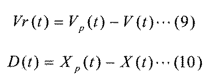
車間距離の予測値と相対速度の予測値を基に、自車の目標駆動力予測値Fa(t)、…、Fa(t+tn)を図6で示した関係を用いて算出し、目標エンジン出力予測値Pe(t)、…、Pe(t+tn)を式(11)で算出する。ここで、ある時刻ts~ts+n秒で減速可能性判断がある場合は、そのときの目標駆動力予測値Fa(ts+ts+n)を負の値に設定し、ある時刻ts~ts+n秒で加速可能性判断がある場合は、そのときの目標駆動力予測値Fa(ts+ts+n)を正の値に設定する。
Based on the predicted value of the inter-vehicle distance and the predicted value of the relative speed, the target driving force predicted value F a (t),..., F a (t + t n ) of the own vehicle is calculated using the relationship shown in FIG. The target engine output predicted value P e (t),..., P e (t + t n ) is calculated by the equation (11). Here, if there is a deceleration possibility determining at a certain time t s ~ t s + n seconds, it sets the target driving force estimated value F a at that time (t s + t s + n ) to a negative value, a certain time t s ~ If there is an acceleration potential determined by t s + n seconds are set that when the target driving force estimated value F a of a (t s + t s + n ) to a positive value.
目標エンジン出力予測値Pe(t)、…、Pe(t+tn)と、目標エンジン出力から最適燃費の目標エンジン回転数を算出する関係1201および目標エンジン出力に対する等出力を担保する最小エンジン回転数の関係1202を用い、目標エンジン回転数の予測値を算出する。図23に示すように、予測した目標エンジン回転数の予測値に、単位時間あたりの目標エンジン回転差に大きな差が生じないように目標値を補正することで、エンジンの回転数変動を抑制し、運転性を向上することができる。また、減速あるいは加速可能性がある時刻tまでは、エンジン回転数を保持させてもよく、これにより、エンジン回転数の変動を抑制でき、運転性が向上する。
The target engine output predicted value P e (t),..., P e (t + t n ), the relationship 1201 for calculating the target engine speed of the optimum fuel consumption from the target engine output, and the minimum engine speed that ensures equal output with respect to the target engine output A predicted value of the target engine speed is calculated using the number relationship 1202. As shown in FIG. 23, by correcting the target value so that a large difference in the target engine speed difference per unit time does not occur in the predicted value of the predicted target engine speed, fluctuations in the engine speed can be suppressed. , Drivability can be improved. In addition, the engine speed may be held until time t when there is a possibility of deceleration or acceleration, whereby fluctuations in the engine speed can be suppressed, and drivability is improved.
100 車両
101 エンジン
102 変速機
103 最終減速機
104 差動減速機
105 スタータモータ
106 発電機
107 駆動ベルト
108 バッテリ
109 車載電装機器
111 コントローラ
112 アクセル踏み込み量検出部
113 ブレーキ踏み込み量検出部
114 車速検出部
115 ブレーキ機構
116 トルクコンバータ
117 変速機オイルポンプ
118 変速機構
119 クラッチ機構
120 オイルポンプ駆動用チェーン
121 エンジン回転数センサ
122 変速機入力回転数センサ
123 変速機出力回転数センサ
124 変速機用電動オイルポンプ
125 周辺道路情報取得部
126 周辺車両情報取得部
201 加減速可能性判断部
202 目標駆動力演算部
203 目標車両状態演算部
204 目標エンジン出力演算部
205 目標ブレーキトルク演算部
206 エンジン燃料カット要求演算部
207 クラッチ開放要求演算部
208 ロックアップクラッチ開放要求演算部
209 目標エンジン回転数演算部
210 目変速比演算部 DESCRIPTION OFSYMBOLS 100 Vehicle 101 Engine 102 Transmission 103 Final reduction gear 104 Differential reduction gear 105 Starter motor 106 Generator 107 Drive belt 108 Battery 109 In-vehicle electrical equipment 111 Controller 112 Accelerator depression amount detection part 113 Brake depression amount detection part 114 Vehicle speed detection part 115 Brake mechanism 116 Torque converter 117 Transmission oil pump 118 Transmission mechanism 119 Clutch mechanism 120 Oil pump drive chain 121 Engine speed sensor 122 Transmission input speed sensor 123 Transmission output speed sensor 124 Electric oil pump 125 for transmission Road information acquisition unit 126 Surrounding vehicle information acquisition unit 201 Acceleration / deceleration possibility determination unit 202 Target driving force calculation unit 203 Target vehicle state calculation unit 204 Target engine output calculation unit 205 Target brake Torque calculator 206 Engine fuel cut request calculator 207 Clutch release request calculator 208 Lockup clutch release request calculator 209 Target engine speed calculator 210 Eye gear ratio calculator
101 エンジン
102 変速機
103 最終減速機
104 差動減速機
105 スタータモータ
106 発電機
107 駆動ベルト
108 バッテリ
109 車載電装機器
111 コントローラ
112 アクセル踏み込み量検出部
113 ブレーキ踏み込み量検出部
114 車速検出部
115 ブレーキ機構
116 トルクコンバータ
117 変速機オイルポンプ
118 変速機構
119 クラッチ機構
120 オイルポンプ駆動用チェーン
121 エンジン回転数センサ
122 変速機入力回転数センサ
123 変速機出力回転数センサ
124 変速機用電動オイルポンプ
125 周辺道路情報取得部
126 周辺車両情報取得部
201 加減速可能性判断部
202 目標駆動力演算部
203 目標車両状態演算部
204 目標エンジン出力演算部
205 目標ブレーキトルク演算部
206 エンジン燃料カット要求演算部
207 クラッチ開放要求演算部
208 ロックアップクラッチ開放要求演算部
209 目標エンジン回転数演算部
210 目変速比演算部 DESCRIPTION OF
Claims (11)
- 自車の周辺情報を取得する周辺車両情報取得部と
前記周辺車両情報取得部からの周辺情報を基に、自車の加速可能性、又は減速可能性を判断する加減速可能性判断部と、を備え、
自動加減速制御において、目標車速となるように加速を行っている状態において、前記加減速可能性判断部により減速可能性があると判断された場合は、あらかじめ定められた目標エンジン回転数よりも小さくなるように目標エンジン回転数を補正する目標エンジン回転数演算部と、
前記目標エンジン回転数演算部により補正された目標エンジン回転数となるようにエンジンを制御するエンジン制御部と、を備えた車両制御装置。 A surrounding vehicle information acquisition unit that acquires the surrounding information of the host vehicle, and an acceleration / deceleration possibility determination unit that determines the possibility of acceleration or deceleration of the host vehicle based on the surrounding information from the surrounding vehicle information acquisition unit; With
In automatic acceleration / deceleration control, when the acceleration / deceleration possibility determination unit determines that there is a possibility of deceleration in the state where acceleration is performed to achieve the target vehicle speed, A target engine speed calculator for correcting the target engine speed so as to decrease;
A vehicle control device comprising: an engine control unit that controls the engine so that the target engine speed is corrected by the target engine speed calculation unit. - 自車の周辺情報を取得する周辺車両情報取得部と
前記周辺車両情報取得部からの周辺情報を基に、自車の加速可能性、又は減速可能性を判断する加減速可能性判断部と、を備え、
自動加減速制御において、目標車速となるように減速を行っている状態において、前記加減速可能性判断部により加速可能性があると判断された場合は、あらかじめ定められた目標エンジン回転数よりも大きくなるように目標エンジン回転数を補正する目標エンジン回転数演算部と、
前記目標エンジン回転数演算部により補正された目標エンジン回転数となるようにエンジンを制御するエンジン制御部と、を備えた車両制御装置。 A surrounding vehicle information acquisition unit that acquires the surrounding information of the host vehicle, and an acceleration / deceleration possibility determination unit that determines the possibility of acceleration or deceleration of the host vehicle based on the surrounding information from the surrounding vehicle information acquisition unit; With
In the automatic acceleration / deceleration control, when the acceleration / deceleration possibility determination unit determines that there is a possibility of acceleration in a state where the vehicle is decelerating to the target vehicle speed, the acceleration / deceleration control unit determines that the acceleration is greater than a predetermined target engine speed. A target engine speed calculator for correcting the target engine speed so as to increase;
A vehicle control device comprising: an engine control unit that controls the engine so that the target engine speed is corrected by the target engine speed calculation unit. - 請求項1に記載の車両制御装置において、
第1の加速モードと、前記第1の加速モードより加速レベルが小さい第2の加速モードを有し、前記目標エンジン回転数演算部は加速中の減速可能性に基づき、第1または第2の加速モードを選択する車両制御装置。 The vehicle control device according to claim 1,
A first acceleration mode and a second acceleration mode having an acceleration level lower than that of the first acceleration mode, and the target engine speed calculation unit determines whether the first or second acceleration is based on the possibility of deceleration during acceleration. A vehicle control device that selects an acceleration mode. - 請求項1に記載の車両制御装置において、
前記目標エンジン回転数演算部は加速中の減速可能性に基づき、あらかじめ定められた加速レベルよりも小さい加速レベルになるように目標エンジン回転数を補正する車両制御装置。 The vehicle control device according to claim 1,
The target engine speed calculation unit corrects the target engine speed so that the acceleration level is lower than a predetermined acceleration level based on the possibility of deceleration during acceleration. - 請求項1に記載の車両制御装置において、
前記加減速可能性判断部により減速可能性があると判断された時点で既にエンジン出力が目標出力に達している場合には、前記エンジン制御部は、補正前の目標エンジン回転数となるようにエンジンを制御する車両制御装置。 The vehicle control device according to claim 1,
When the engine output has already reached the target output when the acceleration / deceleration possibility determination unit determines that there is a possibility of deceleration, the engine control unit sets the target engine speed before correction to the target engine speed. A vehicle control device for controlling the engine. - 請求項2に記載の車両制御装置において、
第1の減速モードと、前記第1の減速モードより減速レベルが小さい第2の減速モードを有し、前記目標エンジン回転数演算部は減速中の加速可能性に基づき、第1または第2の減速モードを選択することを特徴とする車両制御装置。 The vehicle control device according to claim 2,
A first deceleration mode and a second deceleration mode having a lower deceleration level than that of the first deceleration mode, and the target engine speed calculation unit determines whether the first or second deceleration mode is based on the acceleration possibility during deceleration. A vehicle control device that selects a deceleration mode. - 請求項2に記載の車両制御装置において、
前記目標エンジン回転数演算部は減速中の加速可能性に基づき、あらかじめ定められた減速レベルよりも大きい減速レベルになるように目標エンジン回転数を補正する車両制御装置。 The vehicle control device according to claim 2,
The target engine rotational speed calculation unit corrects the target engine rotational speed so as to obtain a deceleration level higher than a predetermined deceleration level based on the possibility of acceleration during deceleration. - 請求項1に記載の車両制御装置において、
前記加減速可能性判断部は、交差点までの距離、信号機の情報、先行車の加速度、自車の舵角操作量、自車のウィンカ操作、カーブまでの距離、カーブの曲率、並走車の位置あるいは速度情報に基づいて加速中の減速可能性を判断する車両制御装置。 The vehicle control device according to claim 1,
The acceleration / deceleration possibility determination unit is configured to determine the distance to the intersection, traffic signal information, acceleration of the preceding vehicle, the steering angle operation amount of the own vehicle, the winker operation of the own vehicle, the distance to the curve, the curvature of the curve, the parallel running vehicle A vehicle control device that determines the possibility of deceleration during acceleration based on position or speed information. - 請求項2に記載の車両制御装置において、
前記加減速可能性判断部は、交差点までの距離、信号機の情報、先行車の加速度、自車の舵角操作量、自車のウィンカ操作、道路幅に基づいて減速中の加速可能性を判断する車両制御装置。 The vehicle control device according to claim 2,
The acceleration / deceleration possibility determination unit determines the possibility of acceleration during deceleration based on the distance to the intersection, traffic signal information, acceleration of the preceding vehicle, the steering angle operation amount of the own vehicle, the winker operation of the own vehicle, and the road width. Vehicle control device. - 請求項1に記載の車両制御装置において、
前記目標エンジン回転数演算部は、加速における目標出力を出力可能な最小エンジン回転数以上となるように目標エンジン回転数を補正する車両制御装置。 The vehicle control device according to claim 1,
The target engine speed calculation unit is a vehicle control device that corrects the target engine speed so that the target engine speed is equal to or higher than a minimum engine speed that can output a target output in acceleration. - 請求項1に記載の車両制御装置において、
前記加減速可能性判断部により減速可能性があると判断された時点で既にエンジン出力が目標出力に達している場合には、前記エンジン制御部は、エンジン特性において最適燃費付近の目標エンジン回転数となるようにエンジンを制御する車両制御装置。 The vehicle control device according to claim 1,
When the engine output has already reached the target output at the time when the acceleration / deceleration possibility determination unit determines that there is a possibility of deceleration, the engine control unit determines that the target engine speed near the optimum fuel consumption is the engine characteristic. A vehicle control device that controls the engine so that
Priority Applications (4)
| Application Number | Priority Date | Filing Date | Title |
|---|---|---|---|
| EP17855427.5A EP3521594B1 (en) | 2016-09-28 | 2017-08-02 | Vehicle control device |
| CN201780032849.9A CN109715920B (en) | 2016-09-28 | 2017-08-02 | Vehicle control device |
| JP2018541964A JP6554239B2 (en) | 2016-09-28 | 2017-08-02 | Vehicle control device |
| US16/314,567 US11052895B2 (en) | 2016-09-28 | 2017-08-02 | Vehicle control unit |
Applications Claiming Priority (2)
| Application Number | Priority Date | Filing Date | Title |
|---|---|---|---|
| JP2016-188984 | 2016-09-28 | ||
| JP2016188984 | 2016-09-28 |
Publications (1)
| Publication Number | Publication Date |
|---|---|
| WO2018061469A1 true WO2018061469A1 (en) | 2018-04-05 |
Family
ID=61759413
Family Applications (1)
| Application Number | Title | Priority Date | Filing Date |
|---|---|---|---|
| PCT/JP2017/027986 WO2018061469A1 (en) | 2016-09-28 | 2017-08-02 | Vehicle control device |
Country Status (5)
| Country | Link |
|---|---|
| US (1) | US11052895B2 (en) |
| EP (1) | EP3521594B1 (en) |
| JP (1) | JP6554239B2 (en) |
| CN (1) | CN109715920B (en) |
| WO (1) | WO2018061469A1 (en) |
Cited By (1)
| Publication number | Priority date | Publication date | Assignee | Title |
|---|---|---|---|---|
| JP2020121679A (en) * | 2019-01-31 | 2020-08-13 | トヨタ自動車株式会社 | Braking/driving force control system |
Families Citing this family (9)
| Publication number | Priority date | Publication date | Assignee | Title |
|---|---|---|---|---|
| KR102463720B1 (en) * | 2017-12-18 | 2022-11-07 | 현대자동차주식회사 | System and Method for creating driving route of vehicle |
| JP6958385B2 (en) * | 2018-01-24 | 2021-11-02 | トヨタ自動車株式会社 | Vehicle control system |
| JP7000214B2 (en) * | 2018-03-20 | 2022-01-19 | 本田技研工業株式会社 | Vehicle control device |
| US11279344B2 (en) * | 2018-11-30 | 2022-03-22 | International Business Machines Corporation | Preemptive mitigation of collision risk |
| JP6913716B2 (en) * | 2019-07-17 | 2021-08-04 | 本田技研工業株式会社 | Vehicle control devices, vehicle control methods, and programs |
| JP7161458B2 (en) * | 2019-09-09 | 2022-10-26 | 本田技研工業株式会社 | VEHICLE CONTROL DEVICE, VEHICLE CONTROL METHOD, AND PROGRAM |
| KR20220078772A (en) * | 2020-12-03 | 2022-06-13 | 현대모비스 주식회사 | Intersection driving system and method for vehicle |
| CN112728068B (en) * | 2020-12-21 | 2021-12-21 | 厦门雅迅网络股份有限公司 | Vehicle energy-saving control method, storage medium, vehicle control system and vehicle |
| CN112572458B (en) * | 2020-12-21 | 2022-06-10 | 东软睿驰汽车技术(沈阳)有限公司 | Performance estimation method and device of vehicle speed controller |
Citations (8)
| Publication number | Priority date | Publication date | Assignee | Title |
|---|---|---|---|---|
| JPH099408A (en) * | 1995-06-16 | 1997-01-10 | Aisin Aw Co Ltd | Controller of drive power for vehicle |
| JP2002295283A (en) * | 2001-03-30 | 2002-10-09 | Aisin Aw Co Ltd | Device for and method of controlling drive for hybrid vehicle, and program thereof |
| JP3736400B2 (en) | 2001-08-31 | 2006-01-18 | 株式会社デンソー | Vehicle travel control device |
| JP2011058434A (en) * | 2009-09-10 | 2011-03-24 | Toyota Motor Corp | Internal combustion engine control device |
| JP2012047148A (en) | 2010-08-30 | 2012-03-08 | Toyota Motor Corp | Control device of vehicle |
| JP2014111397A (en) * | 2012-12-05 | 2014-06-19 | Toyota Motor Corp | Driving force control unit of vehicle |
| JP2015113823A (en) * | 2013-12-16 | 2015-06-22 | 日立建機株式会社 | Work vehicle |
| JP2016027278A (en) * | 2014-06-30 | 2016-02-18 | アイシン精機株式会社 | Control device of vehicle and drive system of vehicle |
Family Cites Families (35)
| Publication number | Priority date | Publication date | Assignee | Title |
|---|---|---|---|---|
| DE19623847A1 (en) | 1995-06-16 | 1996-12-19 | Aisin Aw Co | Control of drive unit of hybrid vehicle with IC engine and motor-generator set with recuperative braking system |
| DE10320009A1 (en) | 2003-05-06 | 2004-12-02 | Robert Bosch Gmbh | Method for operating a vehicle |
| JP2008012975A (en) * | 2006-07-04 | 2008-01-24 | Xanavi Informatics Corp | Vehicle traveling control system |
| DE102007003679B4 (en) | 2007-01-25 | 2015-05-07 | Ks Kolbenschmidt Gmbh | Method for producing a piston for an internal combustion engine with a cooling channel, realized by joining the piston upper part and the piston lower part by means of a forging compression connection |
| DE102007036794B4 (en) * | 2007-08-03 | 2014-05-28 | Dr. Ing. H.C. F. Porsche Aktiengesellschaft | Method for determining the driving strategy of a vehicle |
| US7966118B2 (en) * | 2007-12-18 | 2011-06-21 | GM Global Technology Operations LLC | Automatic time headway setting for adaptive cruise control system |
| JP5122994B2 (en) * | 2008-01-31 | 2013-01-16 | 本田技研工業株式会社 | Control method of hydraulic continuously variable transmission |
| JP4655124B2 (en) * | 2008-08-25 | 2011-03-23 | トヨタ自動車株式会社 | Control device for hybrid vehicle |
| US8265850B2 (en) * | 2009-02-02 | 2012-09-11 | GM Global Technology Operations LLC | Method and apparatus for target vehicle following control for adaptive cruise control |
| US8359149B2 (en) * | 2009-02-03 | 2013-01-22 | GM Global Technology Operations LLC | Method for integrating multiple feature adaptive cruise control |
| WO2011101949A1 (en) * | 2010-02-16 | 2011-08-25 | トヨタ自動車株式会社 | Vehicle control device |
| DE102011015509A1 (en) * | 2010-06-30 | 2012-01-05 | Wabco Gmbh | Method and device for controlling at least one driver assistance system of a vehicle and vehicle equipped therewith |
| EP2602463A4 (en) * | 2010-08-04 | 2018-04-11 | Yamaha Hatsudoki Kabushiki Kaisha | Vehicle and drive control device for vehicle |
| CN103189622B (en) * | 2010-11-04 | 2015-04-22 | 丰田自动车株式会社 | Control device for engine |
| DE112012006042B4 (en) * | 2012-03-16 | 2015-10-08 | Mitsubishi Electric Corporation | Alert tone control unit of an acoustic system for an approaching vehicle |
| JP5903311B2 (en) * | 2012-03-30 | 2016-04-13 | 本田技研工業株式会社 | Hybrid vehicle |
| US9457802B2 (en) * | 2012-04-06 | 2016-10-04 | Richard Louis Ponziani | Turn signal controlled regenerative braking and decelerative loading |
| US8930115B2 (en) * | 2013-02-26 | 2015-01-06 | Ford Global Technologies, Llc | Efficiency-based speed control with traffic-compatible speed offsets |
| SE537840C2 (en) | 2013-03-21 | 2015-11-03 | Scania Cv Ab | Controlling an actual speed of a vehicle |
| JP6043249B2 (en) * | 2013-07-29 | 2016-12-14 | 日立オートモティブシステムズ株式会社 | Vehicle control device |
| JP6537780B2 (en) * | 2014-04-09 | 2019-07-03 | 日立オートモティブシステムズ株式会社 | Traveling control device, in-vehicle display device, and traveling control system |
| KR101637738B1 (en) * | 2014-11-20 | 2016-07-20 | 현대자동차주식회사 | Vehicle speed signal selection method and vehicle speed signal adjustment verification method |
| US10081357B2 (en) * | 2016-06-23 | 2018-09-25 | Honda Motor Co., Ltd. | Vehicular communications network and methods of use and manufacture thereof |
| JP6642413B2 (en) * | 2016-12-27 | 2020-02-05 | トヨタ自動車株式会社 | Vehicle travel control device |
| WO2018139212A1 (en) * | 2017-01-25 | 2018-08-02 | パナソニックIpマネジメント株式会社 | Operation control system and operation control method |
| US10752225B2 (en) * | 2017-02-08 | 2020-08-25 | Ford Global Technologies, Llc | Determining friction data of a target vehicle |
| US10137900B2 (en) * | 2017-02-15 | 2018-11-27 | Ford Global Technologies, Llc | Methods for vehicle speed accuracy compensation |
| JP6822309B2 (en) * | 2017-05-16 | 2021-01-27 | 株式会社デンソー | Autonomous driving support device and automatic driving support method |
| US10496099B2 (en) * | 2017-07-18 | 2019-12-03 | Uatc, Llc | Systems and methods for speed limit context awareness |
| US11430331B2 (en) * | 2017-09-08 | 2022-08-30 | Uatc, Llc | Power and thermal management systems and methods for autonomous vehicles |
| US10809741B2 (en) * | 2017-11-17 | 2020-10-20 | Polaris Industries Inc. | Method and system for controlling the speed of a vehicle |
| US10713510B2 (en) * | 2017-12-29 | 2020-07-14 | Waymo Llc | Autonomous vehicle system configured to respond to temporary speed limit signs |
| JP6753895B2 (en) * | 2018-06-15 | 2020-09-09 | 本田技研工業株式会社 | Vehicle control devices, vehicle control methods, and programs |
| JP6861669B2 (en) * | 2018-06-15 | 2021-04-21 | 本田技研工業株式会社 | Vehicle control devices, vehicle control methods, and programs |
| JP6800914B2 (en) * | 2018-06-15 | 2020-12-16 | 本田技研工業株式会社 | Vehicle control devices, vehicle control methods, and programs |
-
2017
- 2017-08-02 JP JP2018541964A patent/JP6554239B2/en active Active
- 2017-08-02 US US16/314,567 patent/US11052895B2/en active Active
- 2017-08-02 EP EP17855427.5A patent/EP3521594B1/en active Active
- 2017-08-02 CN CN201780032849.9A patent/CN109715920B/en active Active
- 2017-08-02 WO PCT/JP2017/027986 patent/WO2018061469A1/en unknown
Patent Citations (8)
| Publication number | Priority date | Publication date | Assignee | Title |
|---|---|---|---|---|
| JPH099408A (en) * | 1995-06-16 | 1997-01-10 | Aisin Aw Co Ltd | Controller of drive power for vehicle |
| JP2002295283A (en) * | 2001-03-30 | 2002-10-09 | Aisin Aw Co Ltd | Device for and method of controlling drive for hybrid vehicle, and program thereof |
| JP3736400B2 (en) | 2001-08-31 | 2006-01-18 | 株式会社デンソー | Vehicle travel control device |
| JP2011058434A (en) * | 2009-09-10 | 2011-03-24 | Toyota Motor Corp | Internal combustion engine control device |
| JP2012047148A (en) | 2010-08-30 | 2012-03-08 | Toyota Motor Corp | Control device of vehicle |
| JP2014111397A (en) * | 2012-12-05 | 2014-06-19 | Toyota Motor Corp | Driving force control unit of vehicle |
| JP2015113823A (en) * | 2013-12-16 | 2015-06-22 | 日立建機株式会社 | Work vehicle |
| JP2016027278A (en) * | 2014-06-30 | 2016-02-18 | アイシン精機株式会社 | Control device of vehicle and drive system of vehicle |
Non-Patent Citations (1)
| Title |
|---|
| See also references of EP3521594A4 |
Cited By (4)
| Publication number | Priority date | Publication date | Assignee | Title |
|---|---|---|---|---|
| JP2020121679A (en) * | 2019-01-31 | 2020-08-13 | トヨタ自動車株式会社 | Braking/driving force control system |
| US11458968B2 (en) | 2019-01-31 | 2022-10-04 | Toyota Jidosha Kabushiki Kaisha | Braking/driving force control system |
| JP7172666B2 (en) | 2019-01-31 | 2022-11-16 | トヨタ自動車株式会社 | Braking/driving force control system |
| US11787403B2 (en) | 2019-01-31 | 2023-10-17 | Toyota Jidosha Kabushiki Kaisha | Braking/driving force control system |
Also Published As
| Publication number | Publication date |
|---|---|
| JPWO2018061469A1 (en) | 2019-03-07 |
| CN109715920A (en) | 2019-05-03 |
| CN109715920B (en) | 2021-10-22 |
| US20190168732A1 (en) | 2019-06-06 |
| EP3521594A1 (en) | 2019-08-07 |
| JP6554239B2 (en) | 2019-07-31 |
| US11052895B2 (en) | 2021-07-06 |
| EP3521594A4 (en) | 2021-01-13 |
| EP3521594B1 (en) | 2023-04-12 |
Similar Documents
| Publication | Publication Date | Title |
|---|---|---|
| JP6554239B2 (en) | Vehicle control device | |
| CN108025750B (en) | Vehicle control device | |
| US20180141540A1 (en) | Vehicle and Control Method for Vehicle | |
| WO2015033707A1 (en) | Vehicle control device | |
| JP2012047148A (en) | Control device of vehicle | |
| KR101618453B1 (en) | one-pedal driving control method of electric car | |
| US20150266415A1 (en) | Brake lamp control device | |
| JP2012214181A (en) | Vehicle control system | |
| US8996275B2 (en) | Control device for vehicle | |
| JP6304082B2 (en) | Vehicle control device | |
| CN110382924B (en) | Transmission control device for vehicle | |
| JP2010241245A (en) | Driving power controller for vehicle | |
| JP4539428B2 (en) | Responsiveness correction for accelerator pedal operation amount in vehicles | |
| US11345345B2 (en) | Method for operating a motor vehicle, and corresponding motor vehicle | |
| JP7006707B2 (en) | Vehicle control method and vehicle control device | |
| JP2006312997A (en) | Shift control system of transmission | |
| JP2005233378A (en) | Controlling method and control device for continuously-variable transmission of vehicles | |
| JP5958649B2 (en) | Control device for hybrid vehicle | |
| JP5163589B2 (en) | Vehicle driving force control device | |
| JP2017115935A (en) | Vehicular shift control device | |
| JP2004010003A (en) | Travel control device | |
| JP2019031153A (en) | Travel control device, vehicle, and travel control method | |
| JP7169151B2 (en) | vehicle controller | |
| JP6697286B2 (en) | Vehicle control device | |
| JP4206762B2 (en) | Control device for automatic transmission |
Legal Events
| Date | Code | Title | Description |
|---|---|---|---|
| ENP | Entry into the national phase |
Ref document number: 2018541964 Country of ref document: JP Kind code of ref document: A |
|
| 121 | Ep: the epo has been informed by wipo that ep was designated in this application |
Ref document number: 17855427 Country of ref document: EP Kind code of ref document: A1 |
|
| NENP | Non-entry into the national phase |
Ref country code: DE |
|
| ENP | Entry into the national phase |
Ref document number: 2017855427 Country of ref document: EP Effective date: 20190429 |