JP2004010003A - Travel control device - Google Patents
Travel control device Download PDFInfo
- Publication number
- JP2004010003A JP2004010003A JP2002170354A JP2002170354A JP2004010003A JP 2004010003 A JP2004010003 A JP 2004010003A JP 2002170354 A JP2002170354 A JP 2002170354A JP 2002170354 A JP2002170354 A JP 2002170354A JP 2004010003 A JP2004010003 A JP 2004010003A
- Authority
- JP
- Japan
- Prior art keywords
- vehicle
- acceleration
- control
- inter
- target
- Prior art date
- Legal status (The legal status is an assumption and is not a legal conclusion. Google has not performed a legal analysis and makes no representation as to the accuracy of the status listed.)
- Granted
Links
Images


Abstract
Description
【0001】
【発明の属する技術分野】
本発明は先行車両を検知し、車間距離を制御しながら追従走行を行う走行制御装置に関する。
【0002】
【従来の技術】
カメラやレーダー等を用いて先行する車両を検出し、先行車両との距離を制御しながらこれに追従して走行する走行制御装置が知られている。このような走行制御装置においては、先行車両が走行状態を変動させた場合に、それに自車両の走行状態を追従させる際に遅れが生じやすく、追従性が悪化しやすい。実開平2−133800号公報に開示されている技術は自車両の追従性を向上させる技術の一例であって、先行車の加減速度に応じて目標車間距離を変更する。これにより、追従性と安全性の向上を図っている。
【0003】
【発明が解決しようとする課題】
しかしながら、この技術においては、目標車間距離を維持するよう制御されるため、先行車両が減速している場合でも、車間距離が開きすぎていると自車両を加速させ、車間距離が接近している場合には、先行車両の加速度が大きい場合でも、減速してしまい制御が運転者の感覚に合致せず、違和感を覚えることがある。
【0004】
そこで本発明は、運転者の感覚に合致した制御により追従性を向上させた走行制御装置を提供することを課題とする。
【0005】
【課題を解決するための手段】
上記課題を解決するため、本発明に係る走行制御装置は、先行車両を検知して車間距離を制御する走行制御装置において、先行車両と自車両との車間距離、相対速度、自車速に基づいて目標車間距離と自車両の目標加減速状態を算出するとともに、先行車両または自車両の加減速状態に応じて目標車間距離と目標加減速状態を調整することを特徴とする。
【0006】
先行車両と自車両の車間距離、相対速度、自車速に応じて目標車間距離、目標加減速状態を設定するとともに、先行車両または自車両の加減速状態に応じて目標車間距離、加減速状態の調整を行うことで、運転者の感覚に合致したきめ細かい制御を行うことができる。
【0007】
例えば、先行車両との車間距離が目標車間距離より離れていても、先行車両の減速を検出した場合には、緩減速を行うことが好ましい。緩減速を行うことにより、先行車両へ緩やかな接近は維持しつつ、不用意な加速を抑制して運転者の感覚に合致させて目標車間距離への移行を続ける。
【0008】
また、自車両の加速中は目標車間距離を他の場合より短く設定し、自車両の減速中は目標車間距離を他の場合より長く設定することが好ましい。これにより、運転者の感覚に合致した走行制御が行える。
【0009】
スロットル制御時に要求加速度を低下させる場合には、スロットル全閉時に得られる加速度を推定し、要求加速度がそれを下回る場合に、ブレーキ制御に切り替えることが好ましい。また、ブレーキ制御時に要求加速度を増加させる場合には、ブレーキオフ時に得られる加速度を推定し、要求加速度がそれを上回る場合に、スロットル開制御に切り替えることが好ましい。これにより、特に勾配路におけるスロットル制御とブレーキ制御の切替をスムーズに行うことができる。
【0010】
【発明の実施の形態】
以下、添付図面を参照して本発明の好適な実施の形態について詳細に説明する。説明の理解を容易にするため、各図面において同一の構成要素に対しては可能な限り同一の参照番号を附し、重複する説明は省略する。
【0011】
図1は本発明に係る走行制御装置を搭載した車両の概略図であり、図2はそのブロック構成図である。この走行制御装置60は、先行車を検知する手段として前方にレーザー光を照射して、その反射光を検知するレーザーレーダーセンサ1が車両前部に配置されている。そして、先行車の検知および車両の走行制御は制御ECU2によって行われ、この制御ECU2は、車間制御ECU20、エンジンECU21、ブレーキECU22からなる。
【0012】
このうち、エンジンECU21は、エンジン3の作動を制御するものであって、制御の中には電子制御式スロットルのスロットルモータ31の作動制御も含まれる。ブレーキECU22は、各車輪に配置されるブレーキの作動を制御するものであって、各ブレーキの制動力はブレーキアクチュエータ4により付与する油圧を制御することで制御される。
【0013】
ECU2には、各輪の車輪速を検出する車輪速センサ50、各ブレーキへ付与される油圧を検出する油圧センサ51、車両の前後方向の加速度を検出するGセンサ52、スロットル開度を検出するスロットル開度センサ53の各出力と前述したレーザーレーダーセンサ1の出力信号が入力されている。
【0014】
次に、この走行制御装置60の動作について説明する。図3は、先行車と自車両の状態を示す図である。図のように先行車をP、自車両をMの符号で表す。本制御は、先行車Pが存在しない場合には、システムをOFFとする。なお、所定の速度で定常走行を行うようにしてもよい。一方、先行車Pが存在する場合には、車間距離を維持して走行するもので、自車両との車間距離Drを目標距離Dtに一致させるとともに、相対速度Vr(自車両Mの車速VM−先行車Pの車速VP)が0となるような制御を行う。
【0015】
図4〜図8は具体的な制御のフローチャートである。以下の制御は、ECU2内部、より具体的には、車間制御ECU20、エンジンECU21、ブレーキECU22が協調して実施するものであり、運転者が追従走行モードに設定してから解除するまでの間、繰り返し実行される。追従走行モードの解除は、図示していない制御スイッチをOFFに切り替える場合のほか、運転者がブレーキペダル、アクセルペダル、シフトレバー等を操作した場合に行われる。
【0016】
まず図4に示されるメイン処理から説明する。ステップS1では、レーザーレーダーセンサ1、車輪速センサ50、油圧センサ51、Gセンサ52、スロットル開度センサ53の各出力が読み込まれる。ステップS2では、読み込まれた出力値を基にしてブレーキECU22が車輪速センサ50の出力値から車速VMを算出し、車間制御ECU20が先行車Pの有無を判別して、先行車Pが存在している場合にはさらに先行車Pとの車間距離Drと先行車Pとの自車両Mの相対速度Vrおよび相対加速度Grを算出する。
【0017】
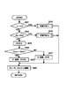
ステップS3では、追従制御を行うための自車両Mの目標加速度Gtを演算する。図5はこのGt演算の詳細を示すフローチャートである。まず、ステップS21では、ベース車間時間Δtbを設定する。ここで、ベース車間時間Δtbとは、ベース車間距離に相当するものであって、自車両Mが現在の速度で走行したときにΔtb後に先行車Pの位置に到達することを意味し、運転者によって設定されるものである。また、定速走行を併用する場合には、運転者は設定車速の設定を行い、このベース車間時間Δtbは、設定車速や実車間距離、実車速VMを基にしてs股間制御ECU2によって設定される。
【0018】
ステップS22では、前回のタイムステップで設定した目標加速度の値Gtoldと閾値Gth2とを比較する。GtoldがGth2以下の場合にはステップS23へと移行し、今度はGtoldを−Gth2と比較する。Gtoldが−Gth2以上の場合にはステップS24へと移行し、今度は前回設定したゆらぎ車間時間Δtfが正であるか否かを判定する。このゆらぎ車間時間Δtfは先行車Pまたは自車両Mの加減速状態に応じて車間時間をベース車間時間Δtbに対して増減させる調整量である。ゆらぎ車間時間Δtfが正でない場合には、ステップS25へと移行してゆらぎ車間時間Δtfが負であるか否かを判定する。ゆらぎ車間時間Δtfが0の場合には、直接ステップS26へと移行し、ベース車間時間Δtbとゆらぎ車間時間Δtfの和を目標車間時間Δtxに設定する。Δtfが0の場合には、Δtx=Δtbとなる。続く、ステップS27でこの目標車間時間Δtxの値から目標車間距離Dtを求め、ステップS28では、目標車間距離Dtと現在の車間距離Drの偏差ΔDおよび相対速度Vrから目標加速度Gtを算出する。このGtの値は、ΔD、Vrに対するマップ値として格納しておけばよい。Gtはその絶対値が相対速度Vrの絶対値および偏差ΔDの絶対値が大きい場合に大きい値を採る。
【0019】
ステップS22でGtoldがGth2を超えていると判定された場合およびステップS24でΔtfが正であった場合には、ステップS30へと移行し、Δtfを所定値Δtfxだけ減らす。続く、ステップS31では、こうして求めたΔtfがΔtfminを下回る場合には、ΔtfをΔtfmin(所定の負の値である)として下限値をΔtfminにガードする。その後、ステップS26へ移行して、目標車間時間Δtxを設定し、目標車間距離Dtを求め(ステップS27)、目標加速度Gtを算出する(ステップS28)。
【0020】
また、ステップS23でGtoldが−Gth2未満であると判定された場合およびステップS25でΔtfが負であった場合には、ステップS35へと移行し、Δtfを所定値Δtfxだけ増やす。続く、ステップS36では、こうして求めたΔtfがΔtfmaxを上回る場合には、ΔtfをΔtfmax(所定の正の値である)として上限値をΔtfmaxにガードする。その後、ステップS26へ移行して、目標車間時間Δtxを設定し、目標車間距離Dtを求め(ステップS27)、目標加速度Gtを算出する(ステップS28)。
【0021】
加速中の場合には、目標車間距離を短めに設定し、逆に減速中の場合には、目標車間距離を長めにとることで運転者の感覚に合わせた車間制御を行うことができる。そして、加減速開始時における急加速、急減速が抑制される。また、ステップS24→30→31およびS25→35→36の処理により、加減速終了時点における車速VMのハンチングが抑制される。
【0022】
こうしてGtを算出したら、図1に示されるステップS4へ移行し、Vr、ΔDが図9に示される所定領域A内にあるか否かを判定する。この所定領域A内にある場合には先行車Pが減速中であると判定する。先行車Pが減速中ではないと判定した場合には、ステップS5へと移行し、相対加速度Grと所定の閾値Gth1(負の値である)とを比較する。相対加速度GrがGth1以上の場合には、ステップS6へと移行し、相対速度Vrと車速VMの関数値f(VM)とを比較する。例えば、f(VM)=−a×VM+bであり、a、bはともに正の定数であって、車速VMがb/a未満の低速時には正、b/aを超える高速時には負の値をとる。Vrがf(VM)以上のときには、ステップS7へと移行する。つまり、先行車Pが減速中でなく(ステップS4)、相対加速度GrがGth1以上(ステップS5)で、相対車速Vrがf(VM)以上(ステップS6)の場合には、制御加速度Gconの値としてステップS3で設定したGtの値をそのまま設定し、ステップS8へと移行して加速度制御を行う。
【0023】
ステップS4で先行車Pが減速中と判定された場合には、ステップS10へと移行して感能制御用加速度GsにΔD、Vrから求まる負の加速度GAを設定する。ステップS5で相対加速度GrがGth1未満と判定された場合(この場合は、相対速度Vrを減速中、つまり、先行車Pより自車両Mの減速が大きいか先行車Pの加速が自車両Mの加速より大きい場合)には、ステップS11へと移行して感能制御用加速度Gsに所定の負の加速度GBを設定する(ここで、GA>GBである)。ステップS6で相対車速Vrがf(VM)未満の場合には、ステップS12へと移行して感能制御用加速度Gsに所定の負の加速度GCを設定する(ここで、GA≧GC>GBである)。
【0024】
Gs設定後はステップS13へと移行し、Gsの補正演算を行う。具体的には、ステップS10〜S12移行後にその状態が所定時間以上継続している場合には、Gsを所定値ΔGs分だけ減少させる。続く、ステップS14では、ステップS3で設定したGtとこうして設定したGsとを比較する。GsがGt以上の場合には、Gtを優先させることとし、ステップS7へと移行して制御加速度Gconの値としてステップS3で設定したGtの値をそのまま設定し、ステップS8へと移行して加速度制御を行う。
【0025】
一方、GsがGt未満の場合には、Gsを優先させることとし、ステップS15へと移行して制御加速度Gconの値としてGsの値を設定し、ステップS8へと移行して加速度制御を行う。
【0026】
これにより、先行車Pが減速している場合には、車間距離に余裕がある場合でも緩い減速を行うことで運転者に安心感を与える制御を行うことができる。車間距離維持を優先すると、加速して車間距離を目標車間距離に一致させてから減速して、相対速度を維持する制御を行うことになるが、本制御のように緩い減速を行うことで、減速しつつ、車間距離を接近させることで、無駄に加速を行うことがなく、燃費の面でも有効であり、また、運転者の感能にも合致する。
【0027】
また、相対加速度Grが所定の負の値未満である場合、先行車Pとの相対速度Vrが減速中の場合には、相対速度が所定値より小さい場合(自車両Mの速度が速い場合には負の値をとる。)には、自車が加速に転じるのを抑制することで無駄な加速を抑制して運転者の感能に合致した制御を行う。
【0028】
図6〜図8はこの加速度制御の実際のフローチャートである。図6がそのメイン処理のフローチャートであり、図7、8はそれぞれその切替判定1、切替判定2の処理を示すフローチャートである。
【0029】
ステップS41では、スロットル開度θが正か否か、つまりスロットル開制御中か否かを判定する。θが正、つまりスロットル開制御中の場合には、後述するステップS48の切替判定1へと移行し、θが0、つまりスロットル開制御中でない場合には、ステップS42へと移行する。ステップS42では、油圧センサ51で検出したブレーキ油圧Pbが所定値P0を超えているか否か、つまり制動制御中か否かを判定する。PbがP0を超えている、つまり制動制御中の場合には、後述するステップS49の切替判定2へと移行する。一方、PbがP0以下、つまり制動制御中でない場合には、ステップS43へと移行して制動制御カウンタibとスロットル制御カウンタitの値をそれぞれ0にリセットする。続く、ステップS44では、制御加速度Gconの値を所定の閾値Gth4と比較する。このGth4は、所定の負の値をとる。GconがGth4を超えている場合には、スロットル制御を行う必要があると判定し、ステップS45へと移行してスロットル開度θtをΔθt増加させ、目標ブレーキ制御油圧Ptを非制動時の油圧P0に設定する。続くステップS46では求めたθt、Ptにしたがってスロットルモータ31、ブレーキアクチュエータ4の作動を制御して終了する。
【0030】
ステップS44で、GconがGth4以下の場合には、制動制御を行う必要があると判定し、ステップS47へと移行してブレーキ制御油圧PtをΔPt増加させ、目標スロットル開度θtを全閉状態である0に設定してステップS46へと移行して作動制御を行う。
【0031】
ステップS48の切替判定1では、まず制動制御カウンタibの値を0にリセットする(ステップS51)。続いてGconの値を閾値Gth3と比較する(ステップS52)。このGth3は、負の値をとる。GconがGth3以上の場合には、自車両の加速度GMからスロットルを制御することで得られる加速度の寄与分G1(θ)を差し引いたGM−G1(θ)とGconとを比較することで、スロットル制御のみで得られる加速度範囲内にGconが存在するか否かを判定する(ステップS53)。ここで、G1(θ)は下り坂の場合を考慮した推定値である。GM−G1(θ)がGconを超えている場合には、その可能性がある場合と判定し、スロットル制御カウンタitの値を1加算する(ステップS54)。そして、ステップS55でitの値が閾値itthを超えているか否かを判定する。itがitth未満と判定した場合にはステップS56へと移行してスロットル制御を継続することとし、GconとGrの偏差に応じて目標スロットル開度θtを増減させ、目標ブレーキ油圧PtはP0のまま維持する。itがitth以上と判定した場合には、スロットル制御継続により目標加速度が達成できていない場合であるから、ステップS57へと移行して目標スロットル開度θtを0にして、目標ブレーキ油圧PtをP0+ΔPtに設定し、ブレーキ制御へと移行する。
【0032】
ステップS53でGM−G1(θ)がGcon以下と判定された場合には、スロットル制御のみでGconを達成することが可能と判定し、itを0にリセットし(ステップS58)、ステップS56へと移行してスロットル制御量θtの設定を行う。
【0033】
ステップS52でGconがGth3以下と判定された場合には、それ以外の場合に比べてスロットル制御では目標加速度(実際には減速指令となる)を達成できない可能性が高いとして、ステップS59へと移行し、まずitを0にリセットし、自車両の加速度GMからスロットルを制御することで得られる加速度の寄与分G2(θ)を差し引いたGM−G2(θ)とGconとを比較することで、スロットルを全閉にした場合に得られる減速度でGconが達成できるか否かを判定する(ステップS60)。ここで、G2(θ)は、平坦路を考慮した推定値であり、G1(θ)より小さい値をとる。
【0034】
GM−G2(θ)がGconを超えている場合には、スロットル制御では減速指令である制御加速度Gconが達成できない場合であると判定して、ステップS57へと移行して目標スロットル開度θtを0にして、目標ブレーキ油圧PtをP0+ΔPtに設定し、ブレーキ制御へと移行する。一方、GM−G2(θ)がGcon以下の場合には、スロットル制御により減速指令である制御加速度Gconが達成できる可能性があると判定して、ステップS56へと移行してスロットル制御量θtの設定を行う。
【0035】
ステップS49の切替判定2では、まずスロットル制御カウンタitの値を0にリセットする(ステップS71)。続いてGconの値を閾値Gth3と比較する(ステップS72)。このGth3は、上述したステップS52で用いた値と同じである。GconがGth3以下の場合には、自車両の加速度GMからブレーキ制御で得られる加速度(実際には減速度であるから負の値をとる)の寄与分G3(Pb)を差し引いたGM−G3(Pb)とGconとを比較することで、ブレーキ制御のみによる減速度調整範囲内にGconが存在しているか否かを判定する(ステップS73)。ここで、G3(Pb)は上り坂の場合を考慮した推定値である。GM−G3(Pb)がGcon未満の場合には、減速度調整範囲を外れている可能性がある場合と判定し、制動制御カウンタibの値を1加算する(ステップS74)。そして、ステップS75でibの値が閾値ibthを超えているか否かを判定する。ibがibth未満と判定した場合にはステップS76へと移行してブレーキ制御を継続することとし、GconとGrの偏差に応じて目標ブレーキ油圧Ptを増減させ、目標スロットル開度θtは0のまま維持する。ibがibth以上と判定した場合には、ブレーキ制御継続により目標加速度が達成できていない場合であるから、ステップS77へと移行して目標ブレーキ油圧Ptを0にして、目標スロットル開度θtをΔθtに設定し、スロットル制御へと移行する。
【0036】
ステップS73でGM−G3(Pb)がGcon以下と判定された場合には、ブレーキ制御のみでGconを達成することが可能と判定し、ibを0にリセットし(ステップS78)、ステップS76へと移行して目標ブレーキ油圧Ptの設定を行う。
【0037】
ステップS72でGconがGth3を超えていると判定された場合には、それ以外の場合に比べてブレーキ制御では目標加速度を達成できない可能性が高いとして、ステップS79へと移行し、まずibを0にリセットし、自車両の加速度GMからブレーキ制御で得られる加速度の寄与分G4(Pb)を差し引いたGM−G4(Pb)とGconとを比較することで、ブレーキによる減速度調整範囲内にGconが存在しているか否かを判定する(ステップS80)。ここで、G4(Pb)は、平坦路を考慮した推定値であり、0>G4(Pb)>G3(Pb)の関係がある。
【0038】
GM−G4(Pb)がGcon未満の場合には、ブレーキ制御では制御加速度Gconが達成できない場合であると判定して、ステップS77へと移行して目標スロットル開度θtをΔθtにして、目標ブレーキ油圧PtをP0に設定し、スロットル制御へと移行する。一方、GM−G4(Pb)がGcon以上の場合には、ブレーキ制御により制御加速度Gconが達成できる可能性があると判定して、ステップS76へと移行してブレーキ制御量Ptの設定を行う。
【0039】
以上のように切替制御を行うことで、ブレーキ、スロットル制御の切替を迅速に行うことができ、特に、登坂時、降坂時において切替の遅れに起因する制御のハンチングの発生を抑制することができる。
【0040】
以上の説明では、先行車Pの減速をマップにより判定する例を説明したが、例えば、先行車P自体の加速度から判定してもよく、あるいは、先行車Pのブレーキランプやハザードランプの点灯を画像入力手段あるいは光センサ等により判定して検出してもよい。
【0041】
【発明の効果】
以上説明したように本発明によれば、先行車両と自車両の車間距離だけでなく、加減速状態に応じて自車両の加減速状態をも調整することで、運転者の感能に合致した走行制御を行うことができる。
【図面の簡単な説明】
【図1】図1は本発明に係る走行制御装置を搭載した車両の概略図である。
【図2】図1のブロック構成図である。
【図3】先行車と自車両の状態を示す図である。
【図4】図1の装置の制御のメイン処理を示すフローチャートである。
【図5】図4における目標加速度演算の詳細を示すフローチャートである。
【図6】図4における加速度制御のメイン処理のフローチャートである。
【図7】図6の切替判定1の処理を示すフローチャートである。
【図8】図6の切替判定2の処理を示すフローチャートである。
【図9】先行車減速判定に用いられる領域マップである。
【符号の説明】
1…レーザーレーダーセンサ、2…制御ECU、3…エンジン、4…ブレーキアクチュエータ、20…車間制御ECU、21…エンジンECU、22…ブレーキECU、31…スロットルモータ、50、…車輪速センサ、51…油圧センサ、52…Gセンサ、53…スロットル開度センサ、60…走行制御装置、P…先行車、M…自車両。[0001]
TECHNICAL FIELD OF THE INVENTION
BACKGROUND OF THE
[0002]
[Prior art]
2. Description of the Related Art There is known a travel control device that detects a preceding vehicle using a camera, a radar, or the like, and that travels following the vehicle while controlling the distance to the preceding vehicle. In such a traveling control device, when the traveling state of the preceding vehicle fluctuates, the traveling state of the host vehicle follows the traveling state, which is likely to cause a delay, and the following performance tends to deteriorate. The technique disclosed in Japanese Utility Model Laid-Open Publication No. 2-133800 is an example of a technique for improving the followability of the host vehicle, and changes the target inter-vehicle distance according to the acceleration / deceleration of the preceding vehicle. Thereby, followability and safety are improved.
[0003]
[Problems to be solved by the invention]
However, in this technology, since control is performed so as to maintain the target inter-vehicle distance, even when the preceding vehicle is decelerating, if the inter-vehicle distance is too wide, the own vehicle is accelerated, and the inter-vehicle distance is approaching. In such a case, even when the acceleration of the preceding vehicle is large, the vehicle decelerates and the control does not match the driver's feeling, so that the driver may feel uncomfortable.
[0004]
Therefore, an object of the present invention is to provide a travel control device in which the followability is improved by control that matches the driver's feeling.
[0005]
[Means for Solving the Problems]
In order to solve the above problem, a travel control device according to the present invention is a travel control device that detects a preceding vehicle and controls a following distance, based on a following distance, a relative speed, and a own vehicle speed between the preceding vehicle and the own vehicle. A target inter-vehicle distance and a target acceleration / deceleration state of the host vehicle are calculated, and the target inter-vehicle distance and the target acceleration / deceleration state are adjusted according to the acceleration / deceleration state of the preceding vehicle or the host vehicle.
[0006]
The target inter-vehicle distance, relative speed, the target inter-vehicle distance and the target acceleration / deceleration state are set according to the host vehicle speed, and the target inter-vehicle distance and the acceleration / deceleration state are set according to the acceleration / deceleration state of the preceding vehicle or the host vehicle. By performing the adjustment, it is possible to perform fine control that matches the driver's feeling.
[0007]
For example, even if the inter-vehicle distance to the preceding vehicle is greater than the target inter-vehicle distance, it is preferable to perform slow deceleration when detecting deceleration of the preceding vehicle. By performing slow deceleration, while maintaining a gentle approach to the preceding vehicle, inadvertent acceleration is suppressed, and the shift to the target inter-vehicle distance is continued in accordance with the driver's sense.
[0008]
In addition, it is preferable that the target inter-vehicle distance is set shorter than the other cases during the acceleration of the own vehicle, and the target inter-vehicle distance is set longer than the other cases during the deceleration of the own vehicle. As a result, traveling control that matches the driver's feeling can be performed.
[0009]
When the required acceleration is reduced during the throttle control, it is preferable to estimate the acceleration obtained when the throttle is fully closed, and to switch to the brake control when the required acceleration is lower than that. Further, when increasing the required acceleration during the brake control, it is preferable to estimate the acceleration obtained when the brake is off, and to switch to the throttle opening control when the required acceleration exceeds it. This makes it possible to smoothly switch between the throttle control and the brake control, particularly on a slope road.
[0010]
BEST MODE FOR CARRYING OUT THE INVENTION
Hereinafter, preferred embodiments of the present invention will be described in detail with reference to the accompanying drawings. In order to facilitate understanding of the description, the same components are denoted by the same reference numerals as much as possible in each drawing, and redundant description is omitted.
[0011]
FIG. 1 is a schematic diagram of a vehicle equipped with a travel control device according to the present invention, and FIG. 2 is a block diagram of the vehicle. The travel control device 60 includes a
[0012]
Among them, the engine ECU 21 controls the operation of the engine 3, and the control includes the operation control of the
[0013]
The ECU 2 includes a
[0014]
Next, the operation of the travel control device 60 will be described. FIG. 3 is a diagram illustrating a state of the preceding vehicle and the own vehicle. As shown in the figure, the preceding vehicle is represented by P and the own vehicle is represented by M. In this control, when the preceding vehicle P does not exist, the system is turned off. Note that steady traveling may be performed at a predetermined speed. On the other hand, if the preceding vehicle P is present, one that travels while maintaining the inter-vehicle distance, together with the match inter-vehicle distance Dr between the vehicle target distance Dt, the relative speed Vr (the vehicle M speed V M - performing a control such as the vehicle speed V P of the preceding vehicle P) is zero.
[0015]
4 to 8 are flowcharts of specific control. The following control is carried out in cooperation with the ECU 2, more specifically, the headway control ECU 20, the engine ECU 21, and the brake ECU 22. It is executed repeatedly. The following running mode is released when the driver operates a brake pedal, an accelerator pedal, a shift lever, or the like, in addition to a case where a control switch (not shown) is turned off.
[0016]
First, the main processing shown in FIG. 4 will be described. In step S1, the outputs of the
[0017]
In step S3, a target acceleration Gt of the vehicle M for performing the following control is calculated. FIG. 5 is a flowchart showing details of the Gt calculation. First, in step S21, a base inter-vehicle time Δtb is set. Here, the base inter-vehicle time Δtb is equivalent to the base inter-vehicle distance, and means that the vehicle M reaches the position of the preceding vehicle P after Δtb when traveling at the current speed. It is set by. In addition, when using the constant speed traveling, the driver sets the set vehicle speed, and the base inter-vehicle time Δtb is set by the s-
[0018]
In step S22, the value Gtod of the target acceleration set in the previous time step is compared with a threshold value Gth2. When Gtold is equal to or smaller than Gth2, the process proceeds to step S23, and Gtod is compared with -Gth2. If Gtod is equal to or larger than -Gth2, the process proceeds to step S24, and it is determined whether or not the previously set fluctuation inter-vehicle time Δtf is positive. The fluctuation inter-vehicle time Δtf is an adjustment amount for increasing or decreasing the inter-vehicle time with respect to the base inter-vehicle time Δtb according to the acceleration / deceleration state of the preceding vehicle P or the own vehicle M. If the fluctuation inter-vehicle time Δtf is not positive, the flow shifts to step S25 to determine whether or not the fluctuation inter-vehicle time Δtf is negative. If the fluctuation inter-vehicle time Δtf is 0, the process directly proceeds to step S26, and the sum of the base inter-vehicle time Δtb and the fluctuation inter-vehicle time Δtf is set as the target inter-vehicle time Δtx. When Δtf is 0, Δtx = Δtb. Subsequently, in step S27, the target inter-vehicle distance Dt is obtained from the value of the target inter-vehicle time Δtx. In step S28, the target acceleration Gt is calculated from the deviation ΔD between the target inter-vehicle distance Dt and the current inter-vehicle distance Dr and the relative speed Vr. The value of Gt may be stored as a map value for ΔD and Vr. Gt takes a large value when its absolute value is large when the absolute value of the relative speed Vr and the absolute value of the deviation ΔD are large.
[0019]
If it is determined in step S22 that Gtold exceeds Gth2, and if Δtf is positive in step S24, the process proceeds to step S30, where Δtf is reduced by a predetermined value Δtfx. In the following step S31, if Δtf thus obtained is smaller than Δtfmin, Δtf is set to Δtfmin (which is a predetermined negative value), and the lower limit is guarded to Δtfmin. Thereafter, the process proceeds to step S26, where the target inter-vehicle time Δtx is set, the target inter-vehicle distance Dt is obtained (step S27), and the target acceleration Gt is calculated (step S28).
[0020]
When it is determined in step S23 that Gtold is less than -Gth2, and when Δtf is negative in step S25, the process shifts to step S35 to increase Δtf by a predetermined value Δtfx. In step S36, if Δtf thus obtained exceeds Δtfmax, Δtf is set to Δtfmax (which is a predetermined positive value), and the upper limit is guarded to Δtfmax. Thereafter, the process proceeds to step S26, where the target inter-vehicle time Δtx is set, the target inter-vehicle distance Dt is obtained (step S27), and the target acceleration Gt is calculated (step S28).
[0021]
When the vehicle is accelerating, the target inter-vehicle distance is set to be short. On the other hand, when the vehicle is decelerating, the target inter-vehicle distance is set to be long so that the inter-vehicle control can be performed according to the driver's feeling. Then, sudden acceleration and sudden deceleration at the start of acceleration / deceleration are suppressed. Further, the process of step S24 → 30 → 31 and S25 → 35 → 36, the hunting of the vehicle speed V M of the acceleration and deceleration end is suppressed.
[0022]
After Gt is calculated in this manner, the process proceeds to step S4 shown in FIG. 1, and it is determined whether Vr and ΔD are within the predetermined area A shown in FIG. When the vehicle is within the predetermined area A, it is determined that the preceding vehicle P is decelerating. If it is determined that the preceding vehicle P is not decelerating, the process proceeds to step S5, where the relative acceleration Gr is compared with a predetermined threshold Gth1 (which is a negative value). If the relative acceleration Gr is greater than or equal Gth1, the process proceeds to step S6, and compares the relative speed Vr and the vehicle speed V M of the function value f (V M). For example, f (V M) = - a a × V M + b, a , b is a both positive constant, positive at the time of low-speed vehicle speed V M is less than b / a, negative at high speeds in excess of b / a Take the value of. Vr is at a higher f (V M), the process proceeds to Step S7. That is, the preceding vehicle P is not decelerating in (step S4), and the relative acceleration Gr is Gth1 more (step S5), and if the relative vehicle speed Vr is f (V M) above (step S6), the control acceleration Gcon The value of Gt set in step S3 is set as it is, and the process proceeds to step S8 to perform acceleration control.
[0023]
If the preceding vehicle P is determined to be decelerating at step S4, [Delta] D in Kan'no control acceleration Gs and proceeds to step S10, it sets the negative acceleration G A obtained from Vr. When it is determined in step S5 that the relative acceleration Gr is less than Gth1 (in this case, the relative speed Vr is being reduced, that is, the deceleration of the host vehicle M is greater than the preceding vehicle P or the acceleration of the host vehicle M is when the acceleration greater than), the process proceeds to step S11 to set the predetermined negative acceleration G B to Kan'no control acceleration Gs (where a G a> G B). When the relative speed Vr is smaller than f (V M) in step S6, the operation proceeds to step S12 to set the predetermined negative acceleration G C in Kan'no control acceleration Gs by (wherein, G A ≧ G C> is a G B).
[0024]
After the setting of Gs, the process proceeds to step S13, and the correction calculation of Gs is performed. Specifically, if the state has continued for a predetermined period of time after the transition from steps S10 to S12, Gs is reduced by a predetermined value ΔGs. In step S14, Gt set in step S3 is compared with Gs set in this way. If Gs is equal to or greater than Gt, priority is given to Gt, and the process proceeds to step S7 to set the value of Gt set in step S3 as it is as the value of the control acceleration Gcon. Perform control.
[0025]
On the other hand, when Gs is less than Gt, priority is given to Gs, the process proceeds to step S15, the value of Gs is set as the value of the control acceleration Gcon, and the process proceeds to step S8 to perform acceleration control.
[0026]
As a result, when the preceding vehicle P is decelerating, even when there is a margin in the inter-vehicle distance, it is possible to perform control that gives a sense of security to the driver by performing gentle deceleration. If priority is given to maintaining the inter-vehicle distance, control is performed to accelerate and make the inter-vehicle distance match the target inter-vehicle distance and then decelerate to maintain the relative speed, but by performing gentle deceleration as in this control, By approaching the inter-vehicle distance while decelerating, unnecessary acceleration is not performed, which is effective in terms of fuel efficiency and also matches the driver's sensitivity.
[0027]
When the relative acceleration Gr is less than a predetermined negative value, when the relative speed Vr with respect to the preceding vehicle P is decelerating, when the relative speed is smaller than a predetermined value (when the speed of the host vehicle M is high) Takes a negative value.), The control that matches the driver's sensitivity is performed by suppressing the vehicle from turning into acceleration, thereby suppressing unnecessary acceleration.
[0028]
6 to 8 are actual flowcharts of the acceleration control. FIG. 6 is a flowchart of the main processing, and FIGS. 7 and 8 are flowcharts showing the processing of the switching
[0029]
In step S41, it is determined whether or not the throttle opening θ is positive, that is, whether or not the throttle opening control is being performed. If θ is positive, that is, the throttle opening control is being performed, the process proceeds to switching
[0030]
In step S44, when Gcon is equal to or smaller than Gth4, it is determined that the braking control needs to be performed, and the process proceeds to step S47 to increase the brake control oil pressure Pt by ΔPt and to set the target throttle opening θt in the fully closed state. A certain value is set to 0, and the process proceeds to step S46 to perform operation control.
[0031]
In the switching
[0032]
When the G M -G1 (theta) is less than or equal to Gcon in step S53, it determines that it is possible to achieve Gcon only throttle control to reset the it to 0 (step S58), to step S56 Then, the throttle control amount θt is set.
[0033]
If it is determined in step S52 that Gcon is equal to or smaller than Gth3, it is determined that there is a high possibility that the target acceleration (actually, a deceleration command) cannot be achieved by throttle control as compared with other cases, and the process proceeds to step S59. it was, first reset it to zero, comparing the vehicle acceleration G contribution of the acceleration obtained by controlling the throttle G2 from M (theta) minus G M -G2 and (theta) GCON Then, it is determined whether or not Gcon can be achieved at the deceleration obtained when the throttle is fully closed (step S60). Here, G2 (θ) is an estimated value in consideration of a flat road, and takes a value smaller than G1 (θ).
[0034]
If G M -G2 the (theta) exceeds the Gcon, it is determined that the throttle control is a case of controlling the acceleration Gcon a deceleration command can not be achieved, the target throttle opening θt and proceeds to step S57 Is set to 0, the target brake hydraulic pressure Pt is set to P0 + ΔPt, and the process shifts to brake control. On the other hand, if G M -G2 (θ) is less than Gcon, it is determined that the control acceleration Gcon a deceleration instruction by the throttle control could be achieved, the throttle control amount proceeds to step S56 [theta] t Make the settings for
[0035]
In the switching
[0036]
When the G M -G3 (Pb) is less than or equal to Gcon in step S73, it determines that it is possible to achieve Gcon only brake control to reset the ib to 0 (step S78), to step S76 Then, the target brake hydraulic pressure Pt is set.
[0037]
When it is determined in step S72 that Gcon exceeds Gth3, it is determined that there is a higher possibility that the target acceleration cannot be achieved by the brake control as compared with other cases, and the process proceeds to step S79. reset to the own vehicle G M -G4 from the acceleration G M obtained by subtracting the contribution G4 (Pb) of the acceleration obtained by the brake control and (Pb) by comparing the GCON, the deceleration adjustment range of the brake It is determined whether or not Gcon exists (step S80). Here, G4 (Pb) is an estimated value in consideration of a flat road, and has a relationship of 0> G4 (Pb)> G3 (Pb).
[0038]
If G M -G4 (Pb) is less than Gcon, the brake control is determined to be a case where the control acceleration Gcon can not be achieved, and the target throttle opening θt to Δθt and proceeds to step S77, the target The brake hydraulic pressure Pt is set to P0, and the operation shifts to the throttle control. On the other hand, if G M -G4 (Pb) is greater than or equal Gcon, it is determined that the control acceleration Gcon by the brake control may be able to achieve, to set the brake control amount Pt and proceeds to step S76 .
[0039]
By performing the switching control as described above, the switching between the brake and the throttle control can be rapidly performed, and particularly, it is possible to suppress the occurrence of the hunting of the control due to the delay of the switching at the time of climbing up or downhill. it can.
[0040]
In the above description, an example has been described in which the deceleration of the preceding vehicle P is determined based on the map. For example, the determination may be made from the acceleration of the preceding vehicle P itself, or the lighting of the brake lamp or the hazard lamp of the preceding vehicle P may be performed. The determination may be made by image input means or an optical sensor or the like.
[0041]
【The invention's effect】
As described above, according to the present invention, not only the inter-vehicle distance between the preceding vehicle and the host vehicle, but also the acceleration / deceleration state of the host vehicle is adjusted according to the acceleration / deceleration state, thereby matching the driver's sensitivity. Travel control can be performed.
[Brief description of the drawings]
FIG. 1 is a schematic view of a vehicle equipped with a travel control device according to the present invention.
FIG. 2 is a block configuration diagram of FIG. 1;
FIG. 3 is a diagram showing states of a preceding vehicle and a host vehicle.
FIG. 4 is a flowchart showing a main process of control of the apparatus of FIG. 1;
FIG. 5 is a flowchart showing details of a target acceleration calculation in FIG. 4;
FIG. 6 is a flowchart of a main process of the acceleration control in FIG. 4;
FIG. 7 is a flowchart illustrating a process of switching
FIG. 8 is a flowchart illustrating a process of switching
FIG. 9 is an area map used for a preceding vehicle deceleration determination.
[Explanation of symbols]
REFERENCE SIGNS
Claims (6)
先行車両と自車両との車間距離、相対速度、自車速に基づいて目標車間距離と自車両の目標加減速状態を算出するとともに、先行車両または自車両の加減速状態に応じて前記目標車間距離と前記目標加減速状態を調整することを特徴とする走行制御装置。In a travel control device that detects a preceding vehicle and controls the inter-vehicle distance,
A target inter-vehicle distance and a target acceleration / deceleration state of the host vehicle are calculated based on the inter-vehicle distance between the preceding vehicle and the host vehicle, a relative speed, and the host vehicle speed, and the target inter-vehicle distance is calculated according to the acceleration / deceleration state of the preceding vehicle or the host vehicle. And a target acceleration / deceleration state.
Priority Applications (1)
| Application Number | Priority Date | Filing Date | Title |
|---|---|---|---|
| JP2002170354A JP3901024B2 (en) | 2002-06-11 | 2002-06-11 | Travel control device |
Applications Claiming Priority (1)
| Application Number | Priority Date | Filing Date | Title |
|---|---|---|---|
| JP2002170354A JP3901024B2 (en) | 2002-06-11 | 2002-06-11 | Travel control device |
Publications (2)
| Publication Number | Publication Date |
|---|---|
| JP2004010003A true JP2004010003A (en) | 2004-01-15 |
| JP3901024B2 JP3901024B2 (en) | 2007-04-04 |
Family
ID=30436642
Family Applications (1)
| Application Number | Title | Priority Date | Filing Date |
|---|---|---|---|
| JP2002170354A Expired - Fee Related JP3901024B2 (en) | 2002-06-11 | 2002-06-11 | Travel control device |
Country Status (1)
| Country | Link |
|---|---|
| JP (1) | JP3901024B2 (en) |
Cited By (5)
| Publication number | Priority date | Publication date | Assignee | Title |
|---|---|---|---|---|
| JP2007261417A (en) * | 2006-03-28 | 2007-10-11 | Toyota Motor Corp | Vehicle traveling controller and vehicle traveling control method |
| US20100299044A1 (en) * | 2007-11-26 | 2010-11-25 | Equos Research Co., Ltd. | Vehicle control device |
| JP2011005920A (en) * | 2009-06-25 | 2011-01-13 | Masahiro Watanabe | Vehicle travel control method |
| JP2018103712A (en) * | 2016-12-26 | 2018-07-05 | 株式会社デンソー | Travel control device |
| JP7449910B2 (en) | 2021-10-14 | 2024-03-14 | ダイハツ工業株式会社 | Vehicle control device |
-
2002
- 2002-06-11 JP JP2002170354A patent/JP3901024B2/en not_active Expired - Fee Related
Cited By (7)
| Publication number | Priority date | Publication date | Assignee | Title |
|---|---|---|---|---|
| JP2007261417A (en) * | 2006-03-28 | 2007-10-11 | Toyota Motor Corp | Vehicle traveling controller and vehicle traveling control method |
| US20100299044A1 (en) * | 2007-11-26 | 2010-11-25 | Equos Research Co., Ltd. | Vehicle control device |
| US8352147B2 (en) * | 2007-11-26 | 2013-01-08 | Equos Research Co., Ltd. | Vehicle control device |
| JP2011005920A (en) * | 2009-06-25 | 2011-01-13 | Masahiro Watanabe | Vehicle travel control method |
| JP4716340B2 (en) * | 2009-06-25 | 2011-07-06 | 渡邉 雅弘 | Vehicle travel control method |
| JP2018103712A (en) * | 2016-12-26 | 2018-07-05 | 株式会社デンソー | Travel control device |
| JP7449910B2 (en) | 2021-10-14 | 2024-03-14 | ダイハツ工業株式会社 | Vehicle control device |
Also Published As
| Publication number | Publication date |
|---|---|
| JP3901024B2 (en) | 2007-04-04 |
Similar Documents
| Publication | Publication Date | Title |
|---|---|---|
| US11052895B2 (en) | Vehicle control unit | |
| JP3849430B2 (en) | Vehicle travel control device | |
| EP1327554B1 (en) | Vehicle traveling control system | |
| CN101537833B (en) | Driving support device, driving support method, and driving support program | |
| KR102518733B1 (en) | Cruise control system and method for vehicle | |
| JP5397006B2 (en) | Vehicle travel control device | |
| JP2008151334A (en) | Speed-change control device of automatic transmission | |
| JPH10109565A (en) | Vehicle traveling speed control method and device thereof | |
| JP2007276542A (en) | Traveling control device for vehicle | |
| JP2000355236A (en) | Method for setting pressetable ideal vehicle speed and control system | |
| WO2019111309A1 (en) | Vehicle control method and control device | |
| JP3901024B2 (en) | Travel control device | |
| US11345345B2 (en) | Method for operating a motor vehicle, and corresponding motor vehicle | |
| JP3957057B2 (en) | Vehicle traveling control apparatus and method | |
| JP4696409B2 (en) | Vehicle operation support device | |
| JP7006707B2 (en) | Vehicle control method and vehicle control device | |
| JPH0939754A (en) | Starting speed controller | |
| JP2000118369A (en) | Vehicle travel control device | |
| JPH1134696A (en) | Apparatus for controlling inter-vehicle distance | |
| JPH0920160A (en) | Following run controller for vehicle | |
| JPH11348599A (en) | Traveling control device for vehicle | |
| JPH08169251A (en) | Follow-up travel control device for vehicle | |
| JPH08282330A (en) | Follow-up travel controller for vehicle | |
| JP2004268643A (en) | Travel speed control device | |
| JP3387340B2 (en) | Travel control device for vehicles |
Legal Events
| Date | Code | Title | Description |
|---|---|---|---|
| A621 | Written request for application examination |
Free format text: JAPANESE INTERMEDIATE CODE: A621 Effective date: 20050202 |
|
| A977 | Report on retrieval |
Free format text: JAPANESE INTERMEDIATE CODE: A971007 Effective date: 20060621 |
|
| A131 | Notification of reasons for refusal |
Free format text: JAPANESE INTERMEDIATE CODE: A131 Effective date: 20060704 |
|
| A521 | Written amendment |
Free format text: JAPANESE INTERMEDIATE CODE: A523 Effective date: 20060825 |
|
| A131 | Notification of reasons for refusal |
Free format text: JAPANESE INTERMEDIATE CODE: A131 Effective date: 20060919 |
|
| A521 | Written amendment |
Free format text: JAPANESE INTERMEDIATE CODE: A523 Effective date: 20061120 |
|
| TRDD | Decision of grant or rejection written | ||
| A01 | Written decision to grant a patent or to grant a registration (utility model) |
Free format text: JAPANESE INTERMEDIATE CODE: A01 Effective date: 20061212 |
|
| A61 | First payment of annual fees (during grant procedure) |
Free format text: JAPANESE INTERMEDIATE CODE: A61 Effective date: 20061225 |
|
| FPAY | Renewal fee payment (event date is renewal date of database) |
Free format text: PAYMENT UNTIL: 20110112 Year of fee payment: 4 |
|
| FPAY | Renewal fee payment (event date is renewal date of database) |
Free format text: PAYMENT UNTIL: 20110112 Year of fee payment: 4 |
|
| FPAY | Renewal fee payment (event date is renewal date of database) |
Free format text: PAYMENT UNTIL: 20120112 Year of fee payment: 5 |
|
| FPAY | Renewal fee payment (event date is renewal date of database) |
Free format text: PAYMENT UNTIL: 20130112 Year of fee payment: 6 |
|
| LAPS | Cancellation because of no payment of annual fees |