WO2018056228A1 - Cable, device, and electricity supply method - Google Patents
Cable, device, and electricity supply method Download PDFInfo
- Publication number
- WO2018056228A1 WO2018056228A1 PCT/JP2017/033584 JP2017033584W WO2018056228A1 WO 2018056228 A1 WO2018056228 A1 WO 2018056228A1 JP 2017033584 W JP2017033584 W JP 2017033584W WO 2018056228 A1 WO2018056228 A1 WO 2018056228A1
- Authority
- WO
- WIPO (PCT)
- Prior art keywords
- cable
- fiber
- power
- resin
- battery
- Prior art date
Links
Images


Classifications
-
- H—ELECTRICITY
- H05—ELECTRIC TECHNIQUES NOT OTHERWISE PROVIDED FOR
- H05K—PRINTED CIRCUITS; CASINGS OR CONSTRUCTIONAL DETAILS OF ELECTRIC APPARATUS; MANUFACTURE OF ASSEMBLAGES OF ELECTRICAL COMPONENTS
- H05K9/00—Screening of apparatus or components against electric or magnetic fields
- H05K9/0073—Shielding materials
- H05K9/0098—Shielding materials for shielding electrical cables
-
- H—ELECTRICITY
- H01—ELECTRIC ELEMENTS
- H01B—CABLES; CONDUCTORS; INSULATORS; SELECTION OF MATERIALS FOR THEIR CONDUCTIVE, INSULATING OR DIELECTRIC PROPERTIES
- H01B7/00—Insulated conductors or cables characterised by their form
- H01B7/17—Protection against damage caused by external factors, e.g. sheaths or armouring
- H01B7/18—Protection against damage caused by wear, mechanical force or pressure; Sheaths; Armouring
- H01B7/1875—Multi-layer sheaths
-
- H—ELECTRICITY
- H01—ELECTRIC ELEMENTS
- H01B—CABLES; CONDUCTORS; INSULATORS; SELECTION OF MATERIALS FOR THEIR CONDUCTIVE, INSULATING OR DIELECTRIC PROPERTIES
- H01B7/00—Insulated conductors or cables characterised by their form
-
- H—ELECTRICITY
- H01—ELECTRIC ELEMENTS
- H01B—CABLES; CONDUCTORS; INSULATORS; SELECTION OF MATERIALS FOR THEIR CONDUCTIVE, INSULATING OR DIELECTRIC PROPERTIES
- H01B7/00—Insulated conductors or cables characterised by their form
- H01B7/02—Disposition of insulation
-
- H—ELECTRICITY
- H01—ELECTRIC ELEMENTS
- H01B—CABLES; CONDUCTORS; INSULATORS; SELECTION OF MATERIALS FOR THEIR CONDUCTIVE, INSULATING OR DIELECTRIC PROPERTIES
- H01B7/00—Insulated conductors or cables characterised by their form
- H01B7/17—Protection against damage caused by external factors, e.g. sheaths or armouring
- H01B7/28—Protection against damage caused by moisture, corrosion, chemical attack or weather
- H01B7/282—Preventing penetration of fluid, e.g. water or humidity, into conductor or cable
- H01B7/285—Preventing penetration of fluid, e.g. water or humidity, into conductor or cable by completely or partially filling interstices in the cable
- H01B7/288—Preventing penetration of fluid, e.g. water or humidity, into conductor or cable by completely or partially filling interstices in the cable using hygroscopic material or material swelling in the presence of liquid
-
- H—ELECTRICITY
- H01—ELECTRIC ELEMENTS
- H01B—CABLES; CONDUCTORS; INSULATORS; SELECTION OF MATERIALS FOR THEIR CONDUCTIVE, INSULATING OR DIELECTRIC PROPERTIES
- H01B9/00—Power cables
-
- H—ELECTRICITY
- H02—GENERATION; CONVERSION OR DISTRIBUTION OF ELECTRIC POWER
- H02J—CIRCUIT ARRANGEMENTS OR SYSTEMS FOR SUPPLYING OR DISTRIBUTING ELECTRIC POWER; SYSTEMS FOR STORING ELECTRIC ENERGY
- H02J7/00—Circuit arrangements for charging or depolarising batteries or for supplying loads from batteries
-
- H—ELECTRICITY
- H05—ELECTRIC TECHNIQUES NOT OTHERWISE PROVIDED FOR
- H05K—PRINTED CIRCUITS; CASINGS OR CONSTRUCTIONAL DETAILS OF ELECTRIC APPARATUS; MANUFACTURE OF ASSEMBLAGES OF ELECTRICAL COMPONENTS
- H05K3/00—Apparatus or processes for manufacturing printed circuits
Definitions
- the present invention relates to a cable, a device, and a power supply method.
- a metal material centered on aluminum such as aluminum die-casting, is generally used as a shielding material in the case of a casing.
- a braided shield or a horizontal wire is used at low frequencies.
- Aluminum foil tape shields are widely used for winding shields and high frequencies.
- the shield effect refers to a minus effect that shields an electromagnetic wave component that becomes external noise by dropping a potential to ground with a grounded shield.
- the inventor said that the energy efficiency of the electrons flowing through the electrical device is low due to the influence of the inherent frequency of the AC power source used in the device, whether it is a battery-mounted electrical device charged with an AC power source or an ordinary AC power source electrical device. And found the following problems.
- the present invention has been made in view of the above background, and aims to improve the energy efficiency of equipment and the like or improve the sound quality.
- 1st invention of this invention is a cable, a power strip, a battery, a printed circuit board, LSI / IC, other electrical components, or other electrical equipment, moisture absorption fiber, moisture absorption resin, inorganic ion exchanger influence fiber, inorganic ion It has means for adopting, as an outer skin, an exchanger-affected resin, a supercritical effect fiber, or a supercritical effect resin or a fiber / resin that is a composite of the three types of fibers / resins.
- the hygroscopic fiber / resin refers to a polymer fiber / resin obtained by polymerizing a carboxyl group or a hydrophilic group of a carboxyl group salt using a natural fiber / resin or a synthetic fiber / resin as a raw material.
- the second invention includes at least one cable using the outer cover of the first invention as a cable to be used, or includes at least one power strip as the outer cover of the first invention as a power strip to be used, It has means for connecting a plurality of cables having different characteristics in series.
- the third invention is a cable of the first invention, a cable of the second invention, a power strip of the first invention, a battery of the first invention, a printed circuit board of the first invention, an LSI / IC component of the first invention, as the parts used. Or it has a means using other electric parts of the 1st invention.
- the fourth invention relates to a method for charging a battery using the cable of the first invention, the cable of the second invention, or the power strip of the first invention in a battery or an electric device equipped with a battery. Further, the present invention relates to a battery charged by the method and an electric device equipped with the battery.
- another electrical device is connected to a power outlet supplied from the same switchboard as the source of the cable or power strip used for charging of the fourth invention. It is related with the method of charging in the state which energized.
- the basic basic operation which is the basic effect of the present invention will be described.
- it is not a negative negative effect such as the noise blocking effect of the shield, but another positive positive alpha action that raises the energy level of the quantum state of electrons flowing in the electrical equipment or cable.
- This function is a hygroscopic fiber, a hygroscopic resin, an inorganic ion exchanger-affected fiber, an inorganic ion exchanger-affected resin, a supercritical effect fiber, a supercritical effect resin, or a fiber or resin that is a composite of the above three types of fibers or resins. This is a completely new effect different from the original moisture absorption.
- This function is applied to existing cables, power strips, batteries, printed circuit boards, LSIs, ICs, other electrical components, or other electrical devices. It can be easily expressed just by attaching a part of inorganic ion exchanger-affected resin, supercritical effect fiber, supercritical effect resin, or fiber / resin composite of the above three types of fibers / resins.
- superconductivity has a function of significantly increasing the current consumption value by means of ultra-low temperature and does not become ecological.
- the present invention is realized at room temperature and does not change the current value. There is a completely different effect of eco-friendliness by increasing energy efficiency.
- the second invention is for further improving the action of the first invention.
- the conventional common sense overturns the common sense that the shorter the cable, the better, and the use of a plurality of cables with excellent performance, including at least one cable of the solution of the first invention, with different performances connected in series. Therefore, the characteristic unevenness of the frequency characteristics of the energy level of each cable in the state of each cable is averaged, the number of defects is reduced, and all the high frequency parts of the energy state of the quantum state of each cable are convolved and integrated. As a result, the energy level of the quantum state increases over the entire frequency characteristic.
- the performance of the battery changes depending on the quality of the power source such as a cable for charging the battery.
- the first invention or the second invention In the method of charging the battery using the power cable of the present invention or the power strip of the first invention, the effect of changing the performance of the battery charged by that method was discovered for the first time. This is because the energy level of the quantum state of electrons recorded in the battery is high, so that the battery is modified.
- the quantum principle action of the present invention is proved by itself.
- the battery itself is a direct current component having no frequency component, and only the factor of the electron itself is transmitted. It is that the quantum state whose level has been increased is recorded. As a result, it is possible to improve the output of electric equipment using the battery and to extend the usage time. This is an event that proves that the energy level of the quantum state of electrons recorded in the battery is increased and transmitted.
- the degree of this action is the same in both the electric device of the fourth invention equipped with a battery and the electric device of the AC power source of the third invention.
- the moisture absorbing fiber, the moisture absorbing resin, the inorganic ion exchanger-affected fiber, the inorganic ion exchanger-affected resin, the supercritical effect fiber, or the supercritical effect resin is used in the electrical device to perform the above-described function.
- the energy level of the quantum state described in detail for each of the first invention to the fifth invention can be raised.
- the difference between the conventional charging method and the charging method to which the present invention is applied was confirmed by a travel distance measurement experiment per charging of the following electrically assisted bicycle.
- the driving pattern in the standard mode is an industry standard pattern: (1) 1km at 3km flat speed 15km / h, (2) 1km at 2km 4km uphill 10km / h, (3) 1km at 3km flat speed 15km / h (4) By 4 km downhill 3rd speed 20 km / h, repeated 1 km pattern continuously.
- the travel distance measurement of the battery-assisted bicycle with the battery before application of the present invention is 36.18 km. Actual travel distance of battery-powered bicycle after application of the present invention 95.47 km It became.
- the following experiment was conducted as another experiment.
- the illuminance and duration of the LED flashlight were measured using the conventional charging method and the charging method to which the present invention was applied.
- the illuminance and duration before application of the present invention were 19500 lux 1007 minutes
- the illuminance and duration after application of the present invention was 29500 lux 1571 minutes.
- the duration has been extended.
- the energy has increased by about 2.4 times, which is almost the same as the experiment with a power-assisted bicycle. The result which matched is obtained.
- Example 9 As an example for experimental evaluation of the present invention, an experiment using Example 9 described later with reference to FIG. 9 was performed. In addition, this experiment is performed in order to obtain a more accurate experimental result in consideration of the possibility that the measurement error or the like was large in the previous experiment as described later.
- a Bridgestone electrically assisted bicycle BKO85 As a test vehicle, a Bridgestone electrically assisted bicycle BKO85 was used as an experimental condition. A new battery before application of the present invention is charged by connecting a charger 92 attached to the Bridgestone electric assist bicycle BKO85 to a normal wall outlet 82 (see FIG. 9) provided on the wall of the home, and so on.
- the charged battery was attached to the experimental vehicle (Bridgestone Electric Assist Bicycle BKO85), and the distance traveled from FL (100%) to 0% was measured with the indicator attached to the vehicle (hereinafter this normal charging).
- This is also referred to as a battery before application of the present invention, and this charging is also referred to as conventional charging.
- the battery of the present invention is charged with the charger 92 attached to the electrically assisted bicycle, and the battery thus charged is charged. Attached to the experimental vehicle (Bridgestone Electric Assist Bicycle BKO85), the travel distance from FL (100%) to 0% was measured with the indicator attached to the vehicle.
- the experimental vehicle Bridgestone Electric Assist Bicycle BKO85
- the charger 92 attached to the Bridgestone electric assist bicycle BKO85 is directly connected to a normal wall outlet 82 (FIG. 9) provided on the wall of the home. 9 and connected to the battery as shown in FIG. 9 to charge the battery (hereinafter, the battery charged according to the configuration of the present invention is also referred to as a battery after application of the present invention. This charging is also referred to as charging according to the present invention.)
- the constant assisted sustainability test method at a speed of 15 km / h on the flat ground was selected before treatment (battery before application of the present invention) and after treatment (application of the present invention). The choice was made because the later battery) comparison was measured accurately.
- the load on the battery increases or decreases, and the probability that the load is 0% is concentrated. Since the ratio of the travel distance is not required, in order to avoid the problem, the experiment is focused on the accuracy of unifying the continuous travel test in which a constant load is maintained perfectly. This is because, in a complicated multi-load condition, a large load error due to acceleration is likely to occur at a portion where the load is switched, and accurate comparative measurement is difficult.
- Example 9 the following experiment was conducted as another experiment using Example 9. Specifically, when the audio player 90 (Apple / iPOD Shuffle ME949J / A) is charged by a very general charge as described in the previous electric assist bicycle (hereinafter also referred to as conventional charging). .) And the case of performing the charging according to the present invention (hereinafter, also referred to as the charging according to the present invention), a blind sound quality experiment for confirming a change in sound quality was performed.
- the earphone 91 was used to listen to the music by using the earphone of the OHM Electric OHM Canal Inner Blue Blue HP-B140K-A.
- the second track of Perfume / LEVEL3 was used as the audition source to be played, and five listeners were made to audition.
- the number of trials was performed five times for each listener, with one pair before and after the invention process (conventional charging and charging according to the present invention).
- the charging method is to prepare two audio players 90 (Apple / iPOD Shuffle ME949J / A), input the listening source to each audio player 90, and one audio player 90 is provided on the wall of the home. Connect the AC outlet 88 attached to Apple / iPOD Shuffle ME949J / A directly to an ordinary wall outlet 82 (see Fig. 9), and connect the charging cable 89 attached to Apple / iPOD Shuffle ME949J / A to the AC outlet 88. The audio player 90 was connected to the charging cable 89 for charging (conventional charging).
- the sixth power strip 83 (6) from the left in FIG. 9 is connected to the Apple / iPOD Shuffle ME949J / Connect the AC outlet 88 attached to A, connect the charging cable 89 attached to Apple / iPOD Shuffle ME949J / A to the AC outlet 88, and connect the audio player 90 to the charging cable 89 for charging (charging of the present invention) Went.
- cellophane tape is pasted on the audio player 90 that has been charged according to the present invention so that it can be distinguished from the audio player 90 that has been charged in the past.
- the test listener was asked to be in a blindfolded state and listen to the music played on the audio player 90.
- the music player 90 that plays the conventional charging or the audio player 90 that performs the charging according to the present invention plays the music first and then plays the music later. And the order was random.
- the listener himself is in a state where he / she does not know which of the charged audio players 90 is playing a song, and in that state, the listener performs an experiment to select the better sound quality did.
- the volume is exactly the same when the music is played on the audio player 90 that is charged conventionally and the music player 90 that is charged according to the present invention is played.
- the power consumption and current value during charging were confirmed with a clamp meter at the power source of the charger.
- a clamp meter at the power source of the charger.
- no difference in power consumption and current value occurred. This guarantees that the present invention does not deviate from the manufacturer's standard power and current specifications as charging specifications. This can be said to be an improvement in quality, not the amount of power, and the present invention can be said to be an invention that contributes to ecology of power. This can be judged that energy efficiency is increasing.
- the example given here is an example, and is a hygroscopic fiber, a hygroscopic resin, an inorganic ion exchanger-influencing fiber, an inorganic ion exchanger-influencing resin, a supercritical influencing fiber, or a supercritical influencing resin or the three kinds of fibers / Quantum state of electrons by charging batteries of electrical equipment through cables, power strips, batteries, printed boards, LSI / IC components, or other electrical components that employ resin / fiber composite resin As a result, even if the setting is the same, the energy efficiency is increased more electrically than the conventional performance, and a battery with high output energy can be obtained.
- the physical energy output after electrical conversion such as light, sound, magnetism, radio wave, heat, ions, mechanical rotation, etc. is increased more than before with the same general settings for all electrical devices. It is possible to obtain the secondary effect of performing.
- FIG. 1 is a structural diagram of a cable body 1 according to Embodiment 1 of the present invention. It is a structure figure of the power strip 11 which concerns on Example 2 of this invention.
- FIG. 6 is a structural diagram of a battery according to Example 3 of the invention.
- FIG. 6 is a structural diagram of a printed circuit board according to Embodiment 4 of the present invention.
- FIG. 10 is a structural diagram of another electrical component such as an LSI / IC according to Embodiment 5 of the present invention. It is a systematic diagram of the other electric equipment which concerns on Example 6 of this invention. It is a systematic diagram of the cable which concerns on Example 7 of this invention. It is a charge system figure to the electric equipment carrying a battery concerning Example 8 of the present invention. It is a figure for demonstrating the structure of Example 9 of this invention. It is a figure which shows an example of the power cable which can be used for the original power cable of this invention.
- Example 1 is an example in which the present invention is applied to a cable body 1.
- FIG. 1 illustrates a transparent structure, and is schematically illustrated by enlarging the interval of each material for explanation. However, it is actually in close contact.
- the outer circumference of the insulation sheath of the existing cable 7 is wound with a moisture-absorbing fiber 2 (also referred to as a first material) cut to the size of the maximum outer circumference circumference x cable length, and as a sheath 4 for fixing,
- the entire outermost periphery of the cable 7 is carefully wound horizontally with aluminum tape to cover a part of the connector 8 in a cylindrical shape.
- the cable 7 can be any power cable, digital signal cable or analog signal cable.
- the sheath 4 In order to fix the sheath 4 to the connector 8 at both ends of the cable, it is fixed by a heat shrinkable tube 5.
- the heat-shrinkable tube 5 In FIG. 1, the heat-shrinkable tube 5 is schematically drawn in a straight line, but actually, the heat-shrinkable tube 5 is contracted and closely attached to the connector circumference.
- conductive fibers 3 such as Sanderlon (trade name and registered product) manufactured by Nippon Kashiwa Dyeing Co., Ltd. may be wound on the hygroscopic fibers 2 so as to overlap.
- the length of the conductive fiber 3 is longer than the length of the cable 7, it can be shortened to sufficiently increase the effect even when only a part is used.
- the definition of the moisture-absorbing fiber / resin (moisture-absorbing fiber or moisture-absorbing resin) of the present invention is that a natural group / resin or synthetic fiber / resin is used as a raw material, and a hydrophilic group of a carboxyl group or a carboxyl group salt is polymerized.
- a fiber having a larger surface area than the resin is preferable as a moisture absorption effect.
- the type of fiber / resin used as a raw material is not particularly limited in order to exert its action.
- acrylic fiber is generally used as a polymer fiber obtained by polymerizing a hydrophilic group, and an aqueous solution of sodium hydroxide.
- Polyacrylic acid-based fiber hydrolyzed with is most preferred.
- a conductive fiber / resin carrying a conductive metal As a method for enhancing the effect of the present invention, it is preferable to use a conductive fiber / resin carrying a conductive metal.
- the conductive metal loading method is realized by directly loading in the form of a complex, directly by adsorption, or indirectly by a fiber / resin with an inorganic silicon compound, phosphate, sulfonate, etc. it can.
- a substitute for the hygroscopic fiber / resin of the present invention a hygroscopic fiber / resin other than a hygroscopic fiber / resin carrying an inorganic ion exchanger may be used, or a hygroscopic fiber carrying an inorganic ion exchanger to further enhance the effect.
- / Resin may be used.
- the inorganic ion exchanger is preferably zirconium phosphate, zeolite, silica gel, hydroxyapatite, titanium phosphate (titania phosphate), tungsten oxide or the like.
- a fiber / resin carrying an inorganic ion exchanger is preferably subjected to crosslinking treatment with a hydrazine compound.
- a fiber / resin on which an inorganic ion exchanger is supported is further supported with a conductive metal.
- press thermo product name and registered trademark
- Mitsuno Corporation which is a cross-linked acrylic moisture-absorbing heat-generating fiber, ex (trade name) manufactured by Nippon Exlan Industry Co., Ltd., Fast Retailing Co., Ltd.
- Heattech (trade name and registered trademark) manufactured by Aeon Co., Ltd. Heat fact (trade name and registered trademark) manufactured by AEON Co., Ltd., body heater (trade name and registered trademark) manufactured by Ito-Yokado Co., Ltd. ), Eye heat (trade name and registered trademark) manufactured by Japana Co., Ltd., and moist care (trade name and registered trademark) manufactured by Toyobo Co., Ltd., and the like.
- a supercritical porous treatment is performed on the fiber / resin described in Japanese Patent Application Laid-Open No. 2010-13791.
- carbon dioxide is injected into a supercritical carbon dioxide reaction system manufactured by JASCO Corporation with the temperature setting set to 40 ° C., and the fiber / resin is processed for 1 hour.
- the hygroscopic fiber / resin is finally treated to improve the overall performance. It is possible to adopt a material that has been subjected to a supercritical porous treatment at the raw fiber / resin stage individually, but it is more cost effective and effective to treat with the final fiber / resin efficiently.
- the example of carrying out with the final hygroscopic fiber / resin is preferred.
- the fiber As a substitute for the supercritical porous treatment for the fiber described in JP 2010-13791 A, manufactured by JASCO Corporation, the fiber was replaced with water and the temperature was set to 40 ° C. by pressure treatment. Carbon dioxide is injected into the supercritical carbon dioxide reaction system and treated with water for 1 hour. It is also possible to perform a supercritical porous treatment on the fiber / resin by spraying and spraying the fiber / resin with water after the supercritical treatment returning to normal temperature and normal pressure.
- the function of the conductive fiber 3 is further physical enhancement of the conductive fiber.
- the conductive fiber 3 is a conductive fiber in which copper sulfide is supported on an acrylic fiber / nylon fiber, but in this embodiment, the quantum energy, which is a completely different function from the antistatic function, which is the original application, is used. Introduced to raise the level.
- the aluminum tape used as the sheath 4 is an example, but any tape may be used as long as it can be bonded.
- a copper tape may be used to enhance conductivity.
- Aluminum tape is suitable for high frequency systems such as video and digital signals, and copper tape and gold tape are suitable for low frequency systems for audio band signals. Silver tape is suitable for all-round measures in any band.
- the length of the tape of the sheath 4 is also shortened.
- Example 1 is a simple example that can be carried out even by an amateur, but in the case of a cable manufacturer, as a sheath 4, a braided tube of polyester or the like that is generally used as a sheath in the processing of cable products You may go through.
- the second embodiment is an example in which the present invention is applied to the power strip 11.
- the shield for the housing of a general power strip dedicated to audio is made of a material containing aluminum, such as aluminum die cast, for the housing 19 of the power strip 11, and the ground line is connected to the aluminum die cast of the housing 19.
- the shield is realized.
- a means for adhering the moisture absorbing fiber 12 made of the same material as the moisture absorbing fiber exemplified in Example 1 to the casing 19 of the power strip 11 is taken for a new quantum effect completely different from the shielding effect.
- the structure of the moisture absorbing fiber 12, the method of supporting the moisture absorbing fiber 12, the effect of the inorganic ion exchanger, and the method of the porous treatment by supercritical treatment are exactly the same as those of the moisture absorbing fiber 2 of the first embodiment.
- the power strip 11 in FIG. 2 is schematically drawn with the interval between the materials enlarged for the sake of explanation, but is actually in close contact.
- the same moisture absorbing fiber 12 as that of the first embodiment is cut to be smaller than the inner bottom surface of the housing 19 on the bottom surface inside the housing 19 of the existing power strip 11, and a tape for fixing is used.
- the four corner portions of the moisture absorbent fibers 12 are attached to the bottom surface inside the casing 19 of the power strip 11 with aluminum tape.
- the position of the bottom surface inside the casing 19 of the power strip 11 is an example.
- the tape 15 is attached to any position on the outside or inside. Also good. Even if the moisture absorbing fiber 12 is smaller than the surface area of the power strip 11 and only a part of the moisture absorbing fiber 12 is used, the effect is slightly reduced, but it is sufficiently practical.
- the conductive fibers 13 may be stacked on the moisture absorbing fibers 12.
- the size of the conductive fiber 13 is also smaller than the surface area of the power strip 11, and the effect is sufficiently increased even when only a part of the conductive fiber 13 is used.
- the casing 19 of the power strip 11 is aluminum die-cast and has electrical conductivity, the conductive fiber 13 is not overlapped on the moisture absorbent fiber 12 and is located outside the casing 19 of the power strip 11.
- the tape 15 may be applied to any position.
- the aluminum tape of the tape 15 is an example, but any tape that can be bonded may be used.
- a copper tape may be used to enhance conductivity.
- Aluminum tape is suitable for high-frequency measures such as video and digital signals, and copper tape and gold tape are suitable for low-frequency signals in the audio band. Silver tape is suitable for all-round measures in any band. Corresponding to the size of the hygroscopic fibers 12, the size of the tape 15 is also reduced. Since the purpose is simply fixing, the tape 15 need only have the minimum four corner areas.
- Example 2 is a simple example that can be carried out even by an amateur, but in the case of a manufacturer of the power strip 11, the hygroscopic fibers 12 and the conductive fibers 13 are placed on the plate of the aluminum casing 19 of the power strip 11 from above and below. It is also possible to realize this by forming a layered plate with four corners screwed together.
- FIG. 3 shows an embodiment in which the present invention is applied to the battery 21, wherein (1) is a top view, (2) is a front perspective view, and (3) is a side perspective view.
- FIG. 3 is schematically drawn with the interval of each material enlarged for the sake of explanation, it is actually in close contact.
- the bottom surface inside the casing 29 of the battery 21 is pasted with the same moisture absorbing fibers 22 as the moisture absorbing fibers 2 of the first embodiment, and the casing 29 of the battery 21 is made of aluminum tape as a tape 25 for fixing.
- the four corners of the hygroscopic fiber 22 are pasted on the bottom surface inside.
- the size of the hygroscopic fiber 22 is made smaller than the size of the bottom surface inside the casing 29 of the battery 21.
- the aluminum tape of the tape 25 is an example, but any tape may be used as long as it can be bonded.
- a copper tape may be used to enhance conductivity.
- Aluminum tape is suitable for high-frequency measures such as video and digital signals, and copper tape and gold tape are suitable for low-frequency signals in the audio band.
- Silver tape is suitable for all-round measures in any band.
- the position of the bottom surface inside the casing 29 of the battery 21 is an example. However, as long as it is electrically connected to the casing 29 of the battery 21, it may be attached to the outer or inner position with the tape 25. . Even if the moisture absorbing fiber 22 is smaller than the surface area of the battery 21 and only a part thereof, the effect is slightly reduced, but it is sufficiently practical. Specific examples of the moisture absorbing fibers 22, the method of conductive support for the moisture absorbing fibers, the method of the influence of the inorganic ion exchanger, and the method of the porous treatment by supercritical treatment are exactly the same as those in the first embodiment.
- the conductive fibers 23 may be stacked on the hygroscopic fibers 22.
- the size of the conductive fiber 23 is also made smaller than the surface area of the battery 21, so that the effect can be sufficiently increased even if only a part of the conductive fiber 23 is used.
- the housing 29 of the battery 21 is metal and has conductivity, the conductive fiber 23 is positioned at any position outside or inside the housing 29 of the battery 21 without overlapping the hygroscopic fiber 22. You may stick with the tape 25.
- the size of the tape 25 is also reduced. Since the purpose is simply fixing, the tape 25 need only have the minimum four corner areas.
- Example 3 is a simple example that can be carried out even by an amateur, but in the case of the manufacturer of the battery 21, the metal housing plate itself of the battery 21 is sandwiched between the moisture absorbing fibers 22 and the conductive fibers 23 from above and below. It is also possible to realize this by forming a layered plate with four corners screwed in between.
- FIG. 4 shows an embodiment in which the present invention is applied to a printed circuit board 31.
- FIG. 4 is schematically drawn with the interval of each material enlarged for the sake of explanation, it is actually in close contact.
- the fourth embodiment is an example of a two-layer printed circuit board 31 for the sake of simplicity of explanation, and the upper side of the drawing is a dedicated plane for the ground plane, but a multi-layer can be similarly implemented.
- the same hygroscopic fiber 32 as in Example 1 is cut on the surface of the existing printed circuit board 31 that is smaller than the size of the surface of the substrate 39 dedicated to the ground plane, and aluminum is used as a tape 35 for fixing.
- the four corner portions of the hygroscopic fibers 32 are attached to the surface of the printed circuit board 31 dedicated to the ground plane with tape.
- the aluminum tape of the tape 35 is an example, but any tape may be used as long as it can be bonded.
- a copper tape may be used to enhance conductivity.
- Aluminum tape is suitable for high-frequency measures such as video and digital signals, and copper tape and gold tape are suitable for low-frequency signals in the audio band.
- Silver tape is suitable for all-round measures in any band.
- an example of the position of the ground plane dedicated surface of the substrate 39 is shown. However, as long as it is electrically connected to the housing of the ground plane dedicated surface of the substrate 39, it is attached to the outer or inner position with the tape 35. Also good.
- the moisture absorbing fiber 32 is sufficiently practical even if the effect is slightly reduced even if it is smaller than the surface area of the surface of the substrate 39 dedicated to the ground plane.
- Specific examples of the moisture absorbent fibers 32, the method of conductive support for the moisture absorbent fibers, the method of the influence of the inorganic ion exchanger, and the method of the porous treatment by supercritical treatment are exactly the same as in the first embodiment.
- the conductive fibers 33 may be stacked on the moisture absorbing fibers 32.
- the size of the conductive fiber 33 is also smaller than the surface area dedicated to the ground plane of the printed circuit board 31 so that the effect can be sufficiently increased even if only a part is used.
- Example 4 is a simple example that can be carried out even by an amateur, but in the case of a printed circuit board manufacturer, a moisture absorbing fiber 32 or a conductive fiber 33 is sandwiched between the ground plane layers of the printed circuit board, and further layers are formed. It can also be realized by using a multilayer printed circuit board to which is added.
- the fifth embodiment is an embodiment applied to an LSI (Large Scale Integrated circuit) 41.
- the LSI 41 has been described as an example of the electrical component, but the present invention is not limited to the LSI, but can be replaced with all other electrical components such as an IC that can be mounted on a printed circuit board.
- an LSI having a rectangular parallelepiped housing 49 will be described as a representative for the sake of simplicity.
- FIG. 5 is schematically drawn with the interval between the materials enlarged for the sake of explanation, but is actually in close contact.
- FIG. 5 shows that the same hygroscopic fiber 42 as in Example 1 is attached to the ceiling of the casing 49 with an adhesive. It is assumed that the moisture absorbing fiber 42 is cut to a size smaller than the ceiling surface of the casing 49. Even if the moisture absorbing fiber 42 is smaller than the surface area of the casing 49 and only a part of the moisture absorbing fiber 42 is used, it becomes practical enough.
- the specific example of the moisture absorbing fiber 42, the method of conductive support for the moisture absorbing fiber, the method of the influence of the inorganic ion exchanger, and the method of the porous treatment by supercritical treatment are exactly the same as in the first embodiment.
- the conductive fibers 43 may be stacked on the moisture absorbing fibers 42 and bonded with an adhesive.
- the size of the conductive fiber 43 is also made smaller than the surface area of the housing 49, so that the effect can be sufficiently increased even if only a part is used. Therefore, the moisture absorbing fibers 42 and the conductive fibers 43 having a smaller surface area may be bonded.
- the shape of the electrical component is not a rectangular parallelepiped, the only difference is that the hygroscopic fibers 42 and the conductive fibers 43 are cut and bonded in accordance with the shape of the electrical component.
- Example 5 is a simple example that can be carried out even by an amateur, but in the case of an electrical component manufacturer, the plate of the housing 49 itself is sandwiched between the hygroscopic fibers 42 and the conductive fibers 43 in the form of a sandwich. It can also be realized by using an integral plate of the structure.
- the sixth embodiment is an embodiment in which the present invention is applied to the electric device assembly 51.
- the shield of the casing 59 of the general electric equipment assembly 51 is a so-called frame ground that realizes a shield by connecting a ground line to the casing 59.
- the same hygroscopic fiber 2 as exemplified in the first embodiment is adhered to the casing 59 of the electric device assembly 51.
- Specific examples of the moisture absorbing fibers, the method of conductive support for the moisture absorbing fibers, the method of the influence of the inorganic ion exchanger, and the method of the porous treatment by supercritical treatment are exactly the same as those in Example 1. It is based on adhesive means for conductive fibers.
- FIG. 6 shows a system diagram of an embodiment applied to the cable body 1 and the LSI 41 of the first embodiment. It is an example of a system diagram in which the cable body 1 of the first embodiment is used for the battery 21, the printed board 31, the LSI 41, the internal wiring cable, and the external connection cable in the housing 49.
- the LSI 41 attached to the inside of the printed circuit board 31 is drawn as one for convenience of explanation, but represents the electrical component attached to the inside of the printed circuit board 31 as a representative. Signals processed by these electrical components are output from an external cable 55.
- the seventh embodiment is a high-performance cable body 61 connected in series including a plurality of power strips and including the cable body 1 of the first embodiment.
- the high-performance cable body 61 can be easily realized by simply connecting at least one cable body 1 in series among a plurality of cables connected via the relays of the power strips 63 to 65.
- the effect of the cable body 1 to be connected increases as the number of connections increases by connecting two or more cable bodies 1.
- the position including the power strip 11 of the first embodiment is effective at any position, but it is more effective to use the power strip 11 of the first embodiment at the final stage where the outlet of the electric device to be supplied is directly connected. .
- the position including the cable body 1 of the first embodiment is effective at any position, but the cable body 1 of the first embodiment is used for the power strip 11 at the final stage to which the outlet of the electric device to be supplied is directly connected. Is more effective.
- FIG. 7 shows a high performance cable body 61 of the seventh embodiment.
- There is a wall outlet on the left electricity flows from left to right, and it connects to the device on the right. Further, three cables 62, 64, 66 having different frequency characteristics are connected in series, and finally the cable body 1 of the first embodiment is connected.
- a conventional cable body 62 with a strong low range a conventional power strip 63 with a strong low range, a conventional cable body 64 with a strong mid range, a conventional power strip 65 with a strong mid range, and a conventional power strip with a strong high range.
- the cable body 1 of the first embodiment having a high energy level in the whole area is connected in this order.
- one of the cable bodies 1 of the first embodiment is flat and has a high energy level.
- the advantage that the energy level of the quantum state of the electrons further increases in the entire region than in the case of is further generated.
- a metal material such as a casing, shielded wire, or conductive wire
- silver is added to the metal material such as the housing, shielded wire, conductive wire, or the like.
- the midrange becomes stronger, and it can be said that the inclusion of gold or copper in a metal material such as a casing, shield wire, or lead increases the low frequency.
- the eighth embodiment is an embodiment of a method for charging a battery using the cable body 1 and the charging cable of the first embodiment and the power strip of the second embodiment. Charging is performed with any other electrical equipment connected to a power outlet supplied from the same switchboard as the power source of the cable or power strip used for charging.
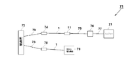
- FIG. 8 is a system diagram of an embodiment of a method for charging a battery-mounted electric device according to the fifth aspect of the present invention.
- the charging system 71 power is supplied to the two wall outlets 74 and 78 through the indoor wiring cable 73 to the same switchboard 72. Furthermore, power is supplied to the power tap 11 from the wall outlet 74 of the first system via the cable body 1 of the first embodiment.
- the power tap 11 is connected to the portable device charging circuit 76 via the power cable 75, and the battery 21 is charged to the portable device charging circuit 76 via the connection cable 77.
- the charging cable 75 even if a conventional charging cable for portable equipment is used, a sufficient effect can be obtained. However, if it is desired to improve the performance, the cable structure of the first embodiment may be used.
- another arbitrary electrical device 79 is energized and connected to the wall outlet 78 of the second system via the cable body 1. Since the purpose of the connection of the second system is only to increase the power consumption, only the condition of energizing and connecting any other electrical device 79 is necessary. This is because the act of charging the first system itself has low power consumption, and the second system is electrically connected to another arbitrary electric device 79 having high power consumption, thereby connecting the quantum state of electrons to the first system. This is because it was discovered for the first time that the energy level of sapphire increases.
- This phenomenon is a novel phenomenon unique to the present invention because it is the first phenomenon that occurs when the cable body 1 or the power strip 11 is used as part of the power environment. This phenomenon is not necessarily achieved via the cable body 1 in the second system if the cable body 1 of the first embodiment is used in part of the first system or the power tap 11 of the second embodiment is used. Even if the power strip 11 of 2 is not used, the effect is sufficient, but even in the second system, it is confirmed that the use of the cable body 1 and the power strip 11 of Examples 1 and 2 is more effective. Yes.
- Example 9 is an example for experiment evaluation of the present invention in a configuration including a specific product name.
- FIG. 9 is a diagram for explaining the configuration of the ninth embodiment.
- a power cable 82 (also simply referred to as a cable) having a strong ultra low frequency (for example, an ultra low frequency range of 20 to 50 Hz) is connected to a normal wall outlet 81 provided on a household wall. To do.
- Purist Audio Design (PAD) / DOMINUS AC Rev. B POWER CABLE which is a power cable made by Purist Audio Design is cited.
- “super bass is strong” is an expression commonly used in the audio field. For example, when a person listens to it, a very low frequency range of 20 to 50 Hz is felt strongly. In the audio field, In addition to signal cables, there are power cables that are tailored to each sound range. Purist Audio Design (PAD) / DOMINUS AC Rev. B POWER CABLE Is known for its extremely low frequencies. The same applies to the following description.
- the power cable 82 is connected to the wall outlet 81 (see C in FIG. 9) as a three-way connector C1 as shown in FIG. The connection is made via the pole conversion connector A.
- the power tap 83 (1) is connected to the side of the power cable 82 opposite to the side connected to the wall outlet 81.
- a representative of the power strip 83 (1) is “BELDEN / POWER TAP PS1850” which is a power strip made by Belden.
- the connector corresponds to the connector C2 which is not the three-way connector C1, and the power cable 82 can be connected as it is.
- a second power cable 82 having a strong ultra-low frequency range is connected to the output side of the power tap 83 (1).
- the outlet C4 on the output side of the power tap 83 (1) corresponds to the three-way connector C1
- the 2-pole / 3-pole conversion connector A is connected as described above. There is no need to connect, and it is directly connected.
- the power strip 83 (2) is connected after the second power cable 82 in the same manner as described above.
- the power strip 83 (1) and the power strip 83 (2) are the same type of power strip, and the description of “(1)” and “(2)” attached later refers to the wall outlet 81 side. No. 4, only the power tap 83 located from there is shown, and the power tap 83 (3) to the power tap 83 (7) coming out later are the same.
- a power cable 84 (also simply referred to as a cable) having a strong mid-low range (for example, a mid-low range of 100 to 300 Hz) is connected to the output side of the power tap 83 (2).
- a representative power cable 84 having a strong mid-low range is “NBS AUDIO CABLES (hereinafter referred to as NBS) / STATEMENT II POWER CABLE 1.5m”, which is a power cable made by NBS.
- the power cable 84 has a three-way connector on one side, and can be directly connected to the outlet on the output side of the power tap 83 (2).
- the power tap 83 (3) is connected. Since the connector that is not the three-way connector of the power cable 84 is a connector corresponding to the input side of the power tap 83 (3), it can be directly connected to the power tap 83 (3).
- a power cable 85 (simply called a cable) having a strong mid-high frequency range (for example, a mid-high frequency range of 2000 to 5000 Hz) is connected to the output side of the power strip 83 (3).
- Connect 4 For example, a typical power cable 85 with a strong mid-high range is the NBS power cable “NBS / BLACK LABEL A / C POWER CABLE 1.8m”.
- This power cable is also a conventional power cable and connector. Since the portions are the same, they can be directly connected to the power strip 83 (3) and the power strip 83 (4).
- the power tap 83 (4) has a wide and strong output on the output side from the middle range (for example, 300 to 2000 Hz midrange) to the very high range (for example, 10,000 to 20000 Hz), that is, 300 Hz to 20000 Hz.
- a strong power cable 86 (also simply referred to as a cable) is connected, and a power tap 83 (5) is connected after the power cable 86.
- the power cable 86 that is wide and strong from the mid-range to the ultra-high range, there is "SYNERGISTIC RESEARCH / DESIGNERS'REFERENCE SQUARED AC MASTER COUPLER POWER CABLE 1.8m" manufactured by Synergistic Research. Since the power cable and the connector portion up to are the same, they can be directly connected to the power tap 83 (4) and the power tap 83 (5).
- the power cable 83 modified by the method shown in the first embodiment is connected to the power tap 83 (5), and the power tap 83 (6) is connected after the power cable 87.
- an original power cable (hereinafter also referred to as an original power cable or an original cable), for example, a power cable made by Yanagida Audio Cable (Yanagita Audio Cable / MASTER2 POWER CABLE) was prepared.
- the power cable made by Yanagida Audio Cable as the original power cable is the same in the power cable and the connector part so far, and is directly connected to the power strip 83 (5) and the power strip 83 (6). be able to.
- Tungsten Co., Ltd.'s Renecat (registered trademark) tungsten oxide-containing liquid is sprayed and sprayed directly over the entire surface of the Moisfine, so that the silver ion nanocolloid liquid and the tungsten oxide-containing liquid are impregnated in this order. Wrap the fine moisture around the former power cable.
- tungsten oxide-containing liquid produced by Toshiba Corporation Renecat (registered trademark) is directly sprayed and sprayed over the entire surface of Sanderlon (registered product), and silver ion nanocolloid liquid and tungsten oxide are thus sprayed.
- Sanderlon impregnated with the contained liquid is wound on the outer circumference of the Moist Fine that was wound around the former power cable.
- the power tap 83 (6) is connected after the power cable 87 obtained by modifying the original power cable as described above.
- the same power cable 87 as described above is connected to the output side of the power tap 83 (6), and the power filter 93 is connected to the power cable 87.
- a representative example of the power filter 93 is “ASUKA / power filter FIL-MASTER-PRO II” manufactured by Asuka Industry Co., Ltd.
- the same power cable 87 as described above is connected to the power filter 93, and a power tap 83 (7) is connected after the power cable 87 in the same manner as before.
- a high-powered audio device 94 with a strong power source is connected to the tap 83 (7).
- “ESOTERIC / CD transport P-0” manufactured by TEAC Co., Ltd. can be cited as a representative of the high-end audio device 94 having a powerful power source.
- a high-end audio device 95 with an ultra-high precision clock is connected to an outlet on the output side different from that to which the high-end audio device 94 of the power strip 83 (7) is connected, and the power strip 83 (7) is connected.
- a high-end audio device 94 and a high-end audio device 95 are connected in parallel.
- “CYBERSHAFT / ultra-high precision OCXO 10 MHz clock PREMIUM” manufactured by Cyber Shaft Co., Ltd. can be cited.
- the high-end audio device 94 and the high-end audio device 95 are turned on during charging, which will be described later.
- the power filter 93, the high-power audio device 94 with a powerful power supply, and the high-end audio device 95 with an ultra-high precision clock are all characterized by including a low ESR (equivalent DC resistance) capacitor unique to the high-end audio device.
- ESR equivalent DC resistance
- the power supply filter 93 includes an ultra-low ESR (equivalent DC resistance) capacitor, has an effect of smoothing noise of the entire power supply, and improves the effect.
- the electric assist bicycle and the audio player 90 described above were charged according to the present invention.
- the charger 92 attached to the electric assist bicycle is connected to the output side of the sixth power tap 83 (6) from the left in FIG. 9 to supply electric power, and the electric assist bicycle according to the present invention is charged. To the battery attached.
- the battery charger 92 attached to the electrically assisted bicycle is directly connected to the wall outlet 81 of FIG. 9 without using the power cable 87 to supply electric power.
- the battery attached to the bicycle is being charged.
- the AC outlet 88 attached to Apple / iPOD Shuffle ME949J / A is connected to the sixth power strip 83 (6) from the left in FIG. 9, and the charging cable 89 attached to Apple / iPOD Shuffle ME949J / A is connected to the AC outlet 88.
- the audio player 90 Apple / iPOD Shuffle ME949J / A
- the charging is a full charge.
- an AC outlet 88 attached to Apple / iPOD Shuffle ME949J / A is connected to the wall outlet 81 shown in FIG. 9, and a charging cable 89 attached to Apple / iPOD Shuffle ME949J / A is connected to the AC outlet 88.
- the audio player 90 (Apple / iPOD Shuffle ME949J / A) is connected to the charging cable 89. This charging is also a full charge.
- the audio player 90 is connected to the earphone 91 which is the Ohm Electric / canal inner phone Blue HP-B140K-A91.
- the charging according to the present invention has a longer traveling distance and better sound quality than the conventional charging.
- Example 9 a power cable made by Yanagita Audio Cable (Yanagita Audio Cable / MASTER2 POWER CABLE) was used as the original power cable, but the original power cable is not limited to this, and the original power cable
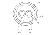
- a general power cable as shown in FIG. 10 as an example can be used.
- the original power cable includes a pair of electric wires CA, a buffer layer B made of a buffer material covering the pair of electric wires CA, a shield layer S such as a copper foil covering the outer periphery of the buffer layer B, and the shield layer S.
- the pair of electric wires CA may also be a general one.
- the electric wire CA includes a single wire conductor M using a conductive material such as copper, and an insulating layer I made of an insulating resin such as polyethylene covering the outer periphery of the single wire conductor M. The thing which has is mentioned.
- Example 1 aluminum tape is used as the sheath 4 for fixing, and in Example 9, the aluminum tape is used for the power cable 87.
- the aluminum tape is not limited to aluminum tape, and the aluminum tape is magnesium. It is good also as metal tapes (metal sheath), such as copper, rhodium, silver, or gold.
- a tape 15 for fixing in the example of the power strip 11 of the second embodiment a tape 25 for fixing in the example of the battery 21 of the third embodiment, and an example of the printed circuit board (substrate) of the fourth embodiment.
- the tape 35 for fixing in the above may be made of a metal tape such as magnesium, copper, rhodium, silver or gold instead of the aluminum tape.
- a metal tape having a refractive index of 1 or less such as aluminum, magnesium, copper, rhodium, silver, or gold, may be used for bonding (attaching) an object to the housing 59.
- the metal tape may be thin or a thin film tape.
- a wide and strong power cable 86 is provided, and before power is supplied to the power cable 87, the power cable 82 having a strong ultra-low frequency, a power cable 84 having a strong mid-low frequency, a power cable 85 having a strong mid-high frequency, and a mid-range power cable
- a wide and strong power cable 86 is interposed up to the ultra high range.
- power cables 82, power cable 84, power cable 85, and power cable 86 are interposed.
- One or more power cables having different frequency characteristics may be interposed to supplement the frequency characteristics of the audible signal so as to increase the audible energy flat over the entire audible band.
- An electronic reforming method characterized by increasing the energy efficiency of electrons flowing to an electrical device via a cable, a power strip, a battery, a printed circuit board, an LSI / IC component, or other electrical components.
- ⁇ Claim 2> A cable in which a plurality of cables having different characteristics including at least one cable according to claim 1 or including at least one power strip according to claim 1 are connected in series.
- ⁇ Claim 3> The cable of claim 1, the cable of claim 2, the power strip of claim 1, the battery of claim 1, the printed circuit board of claim 1, the LSI / IC component of claim 1, or the other electrical of claim 1 Electrical equipment using parts.
- ⁇ Claim 4> A method for charging a battery using the cable according to claim 1, the cable according to claim 2, or the power strip according to claim 1, and a battery charged by the method and an electric device equipped with the battery machine.
- ⁇ Claim 5> 5. A method of charging in a state in which another electrical device is connected to a power outlet supplied from the same switchboard as the source of the cable or power strip used for charging in claim 4 and energized, or a battery charged by the method or the battery Using electrical equipment.
- the electronic reforming method according to the present invention has the possibility of being very widely applicable to electrical equipment, but is particularly applicable to electrical equipment that handles signals having frequency characteristics. Therefore, the present invention can be effectively applied particularly to video-type and audio-type electrical equipment and mechanical motor-type electrical equipment that humans see and listen to. Even when signals with frequency characteristics are not handled, the power energy to be output increases, so the energy output by electrical devices that output energy such as light, sound, magnetism, radio waves, heat, or ions increases. Applicable. Further, by applying the present invention to the charging means of the battery-equipped electric device, there is a possibility that it can be applied to all electric devices equipped with a battery very widely. In addition, with the liberalization of electric power, it is an era when the quality of electric power is questioned, and it can be applied as a basic technology for improving electric power to supply high-quality electric power.
Abstract
Description
第2発明は、用いられるケーブルとして第1発明の外皮を用いたケーブルを最低1本以上含むか、または用いられる電源タップとして第1発明の外皮とした電源タップを最低1台以上含むようにし、特性の異なるケーブルを複数直列に連結した手段を有する。
第3発明は、用いられる部品として第1発明のケーブル、第2発明のケーブル、第1発明の電源タップ、第1発明のバッテリー、第1発明のプリント基板、第1発明のLSI/IC部品、又は、第1発明のその他の電気部品を使用した手段を有する。
第4発明は、バッテリーまたはバッテリー搭載の電気機器において、第1発明のケーブル、第2発明のケーブル、または、第1発明の電源タップを使用してバッテリーに充電する方法に関する。また、その方法で充電したバッテリーおよびそのバッテリーを搭載した電気機器に関する。
第5発明は第4発明のさらなる効果の向上の付加条件として、第4発明の充電に使用されたケーブルまたは電源タップの供給源と同じ配電盤から供給する電源コンセントに、他の電気機器を接続して通電した状態で充電する方法に関する。 1st invention of this invention is a cable, a power strip, a battery, a printed circuit board, LSI / IC, other electrical components, or other electrical equipment, moisture absorption fiber, moisture absorption resin, inorganic ion exchanger influence fiber, inorganic ion It has means for adopting, as an outer skin, an exchanger-affected resin, a supercritical effect fiber, or a supercritical effect resin or a fiber / resin that is a composite of the three types of fibers / resins. Here, the hygroscopic fiber / resin refers to a polymer fiber / resin obtained by polymerizing a carboxyl group or a hydrophilic group of a carboxyl group salt using a natural fiber / resin or a synthetic fiber / resin as a raw material. To do.
The second invention includes at least one cable using the outer cover of the first invention as a cable to be used, or includes at least one power strip as the outer cover of the first invention as a power strip to be used, It has means for connecting a plurality of cables having different characteristics in series.
The third invention is a cable of the first invention, a cable of the second invention, a power strip of the first invention, a battery of the first invention, a printed circuit board of the first invention, an LSI / IC component of the first invention, as the parts used. Or it has a means using other electric parts of the 1st invention.
The fourth invention relates to a method for charging a battery using the cable of the first invention, the cable of the second invention, or the power strip of the first invention in a battery or an electric device equipped with a battery. Further, the present invention relates to a battery charged by the method and an electric device equipped with the battery.
In the fifth invention, as an additional condition for improving the effect of the fourth invention, another electrical device is connected to a power outlet supplied from the same switchboard as the source of the cable or power strip used for charging of the fourth invention. It is related with the method of charging in the state which energized.
第1発明では、シールドのノイズ遮断効果という消極的なマイナス作用ではなく、電気機器又はケーブルに流れる電子の量子状態のエネルギー準位を上げるという積極的なプラスアルファーの全く新しい別の作用である。この作用は、吸湿繊維、吸湿樹脂、無機イオン交換体影響繊維、無機イオン交換体影響樹脂、超臨界影響繊維、超臨界影響樹脂、または、前記3種の繊維または樹脂を複合した繊維または樹脂で得られ、これは本来の吸湿とは別の全く新しい作用である。なお、この作用は、既存のケーブル、電源タップ、バッテリー、プリント基板、LSI、IC、その他の電気部品、または、その他の電気機器に第1発明の吸湿繊維、吸湿樹脂、無機イオン交換体影響繊維、無機イオン交換体影響樹脂、超臨界影響繊維、超臨界影響樹脂、前記3種の繊維/樹脂を複合した繊維/樹脂の材質を一部でも張り付けるだけで容易に発現する。また、比較対象技術として、超電導は超低温という手段により、消費電流値を著しく上昇させてエコにならない作用があるのに対して、本発明は、常温で実現し、電流値を変えずに電子そのもののエネルギー効率を上げることによるエコという全く別の作用がある。 Next, the basic basic operation which is the basic effect of the present invention will be described.
In the first aspect of the present invention, it is not a negative negative effect such as the noise blocking effect of the shield, but another positive positive alpha action that raises the energy level of the quantum state of electrons flowing in the electrical equipment or cable. This function is a hygroscopic fiber, a hygroscopic resin, an inorganic ion exchanger-affected fiber, an inorganic ion exchanger-affected resin, a supercritical effect fiber, a supercritical effect resin, or a fiber or resin that is a composite of the above three types of fibers or resins. This is a completely new effect different from the original moisture absorption. This function is applied to existing cables, power strips, batteries, printed circuit boards, LSIs, ICs, other electrical components, or other electrical devices. It can be easily expressed just by attaching a part of inorganic ion exchanger-affected resin, supercritical effect fiber, supercritical effect resin, or fiber / resin composite of the above three types of fibers / resins. In addition, as a comparison target technology, superconductivity has a function of significantly increasing the current consumption value by means of ultra-low temperature and does not become ecological. On the other hand, the present invention is realized at room temperature and does not change the current value. There is a completely different effect of eco-friendliness by increasing energy efficiency.
結果として
本発明適用前のバッテリーの電動アシスト自転車の走行距離実測
36.18km
本発明適用後のバッテリーの電動アシスト自転車の走行距離実測
95.47km
となった。2015年末時点でのEVのバッテリー技術では、バッテリー全体の部品を良質なものに改質しても約1.5倍が限界であるのに対して、約2.6倍の改善実績は驚異的とも言える技術レベルの性能である。また、EV系以外で、エネルギーが上昇するだけでなくさらにバッテリー容量を増やす副次効果もある。 The difference between the conventional charging method and the charging method to which the present invention is applied was confirmed by a travel distance measurement experiment per charging of the following electrically assisted bicycle. The driving pattern in the standard mode is an industry standard pattern: (1) 1km at 3km flat speed 15km / h, (2) 1km at 2km 4km uphill 10km / h, (3) 1km at 3km flat speed 15km / h (4) By 4 km downhill 3rd speed 20 km / h, repeated 1 km pattern continuously.
As a result, the travel distance measurement of the battery-assisted bicycle with the battery before application of the present invention is 36.18 km.
Actual travel distance of battery-powered bicycle after application of the present invention 95.47 km
It became. EV battery technology at the end of 2015 is about 1.5 times the limit even if the whole battery parts are improved to good quality, while the improvement performance of about 2.6 times is amazing It can be said to be technical level performance. In addition to the EV system, there is a secondary effect of not only increasing energy but also increasing battery capacity.
市販の単三の充電式のニッケル水素電池において、従来の充電方法と、本発明を適用した充電方法でのLED懐中電灯による照度と持続時間を測定した。
結果として
本発明適用前の照度と持続時間 19500ルクス 1007分
本発明適用後の照度と持続時間 29500ルクス 1571分
となった。
照度が大きくなっているのに関わらず、持続時間が延長しているという2つの効果が起こっており、総合的にエネルギーは約2.4倍となっており、ほぼ電動アシスト自転車の実験とつじつまが合う実績が得られた。これにより、本発明適用前よりも本発明適用後にバッテリー容量を増やす効果が証明された。
ただし、照度については、はじめに測定しただけのため、誤差が含まれている可能性があるが、照度が同じであるとしても、持続時間は約1.57倍になっている。 Moreover, the following experiment was conducted as another experiment.
In a commercially available AA rechargeable nickel metal hydride battery, the illuminance and duration of the LED flashlight were measured using the conventional charging method and the charging method to which the present invention was applied.
As a result, the illuminance and duration before application of the present invention were 19500 lux 1007 minutes, and the illuminance and duration after application of the present invention was 29500 lux 1571 minutes.
Despite the fact that the illuminance has increased, two effects have occurred: the duration has been extended. Overall, the energy has increased by about 2.4 times, which is almost the same as the experiment with a power-assisted bicycle. The result which matched is obtained. This proved the effect of increasing the battery capacity after application of the present invention than before application of the present invention.
However, since the illuminance is only measured at the beginning, there may be an error, but even if the illuminance is the same, the duration is about 1.57 times.
なお、本実験は、先の実験では、後述するように、測定誤差等が大きかった可能性を考えて、より正確な実験結果を得るために行っている。
実験車両として、ブリジストン電動アシスト自転車BKO85を実験条件として平地3速15km/hで人漕ぎで連続走行する走行パターンで実験した。
本発明適用前の新品のバッテリーを、家庭の壁に設けられている通常の壁コンセント82(図9参照)にブリジストン電動アシスト自転車BKO85に附属の充電器92を接続して充電し、そのように充電したバッテリーを当該実験車両(ブリジストン電動アシスト自転車BKO85)に取り付けて、当該車両附属の表示計で、FL(100%)から0%になるまでの走行距離を実測した(以下、この通常の充電を行ったものを本発明適用前のバッテリーともいう。また、この充電を従来の充電ともいう。)。 Furthermore, as an example for experimental evaluation of the present invention, an experiment using Example 9 described later with reference to FIG. 9 was performed.
In addition, this experiment is performed in order to obtain a more accurate experimental result in consideration of the possibility that the measurement error or the like was large in the previous experiment as described later.
As a test vehicle, a Bridgestone electrically assisted bicycle BKO85 was used as an experimental condition.
A new battery before application of the present invention is charged by connecting a
つまり、いろいろな傾斜や速度が変わる複雑なマルチ走行負荷による試験であると、バッテリーへの負荷が大きくなったり小さくなったりで、負荷が大きなところで0%になる確率が集中し、厳密な発明前後の走行距離の比率が求められないため、その問題点を回避するために完璧に一定の負荷が持続する連続走行試験に統一しているという精度を重視した実験にしているわけである。
わかりやすくいえば、複雑なマルチ負荷条件では、負荷が切り替わる部分で加速による大幅な負荷の誤差がでやすく正確な比較測定が困難になるためである。 In the experiment using Example 9, the constant assisted sustainability test method at a speed of 15 km / h on the flat ground was selected before treatment (battery before application of the present invention) and after treatment (application of the present invention). The choice was made because the later battery) comparison was measured accurately.
In other words, in a test with a complex multi-running load that varies in various slopes and speeds, the load on the battery increases or decreases, and the probability that the load is 0% is concentrated. Since the ratio of the travel distance is not required, in order to avoid the problem, the experiment is focused on the accuracy of unifying the continuous travel test in which a constant load is maintained perfectly.
This is because, in a complicated multi-load condition, a large load error due to acceleration is likely to occur at a portion where the load is switched, and accurate comparative measurement is difficult.
走行距離実測結果:
本発明適用前のバッテリーの電動アシスト自転車の走行距離実測
79.52km
本発明適用後のバッテリーの電動アシスト自転車の走行距離実測
124.23km The results of actual measurement of the distance traveled by the electrically assisted bicycle using the battery before application of the present invention and the battery after application of the present invention were as follows.
Travel distance measurement result:
Actual travel distance of battery-assisted electric assisted bicycle before application of the present invention 79.52 km
Actual distance traveled by battery-powered bicycle after application of the present invention 124.23 km
この比較は、先に説明したように、精密な一定負荷の連続走行での正確な定量測定になっていることから、発明の効果の度合いが正確に示されたものになっていると言える。 As can be seen from the results, when the battery after application of the present invention is used, the mileage of the electrically assisted bicycle is about 156% as compared with the case of using the battery before application of the present invention that is normally charged. Long results.
As described above, since this comparison is an accurate quantitative measurement in continuous running with a precise and constant load, it can be said that the degree of the effect of the invention is accurately shown.
具体的には、オーディオプレーヤー90(Apple/iPOD Shuffle ME949J/A)の充電を先の電動アシスト自転車で説明したのと同様に、極一般的な充電で行った場合(以下、従来の充電ともいう。)と本発明の充電で行った場合(以下、本発明の充電ともいう。)とで音質の変化を確認するブラインド音質実験を実施した。 In addition, the following experiment was conducted as another experiment using Example 9.
Specifically, when the audio player 90 (Apple / iPOD Shuffle ME949J / A) is charged by a very general charge as described in the previous electric assist bicycle (hereinafter also referred to as conventional charging). .) And the case of performing the charging according to the present invention (hereinafter, also referred to as the charging according to the present invention), a blind sound quality experiment for confirming a change in sound quality was performed.
また、試聴回数は、各試聴者あたり、発明処理前後(従来の充電と本発明の充電)を1ペアとして、5回実施した。 In the blind sound quality experiment, in both the conventional charging and the charging according to the present invention, the
In addition, the number of trials was performed five times for each listener, with one pair before and after the invention process (conventional charging and charging according to the present invention).
ただし、従来の充電が行われているオーディオプレーヤー90と本発明の充電が行われているオーディオプレーヤー90のどちらで先に曲を再生し、どちらで後に曲を再生するから、実験提供者によって決められ、しかも順番をランダムにするようにした。 Then, the test listener was asked to be in a blindfolded state and listen to the music played on the
However, it is determined by the experiment provider because the
なお、従来の充電が行われているオーディオプレーヤー90で曲の再生を行うときも、本発明の充電が行われているオーディオプレーヤー90で曲の再生を行うときも、音量は、全く同一となるように設定した。 For this reason, the listener himself is in a state where he / she does not know which of the charged
It should be noted that the volume is exactly the same when the music is played on the
したがって、1/(2^25)の確率で一致していることから、有意に発明処理後(本発明の充電)の音質の優位性が得られていると結論できる。 As a result of the five test-listeners, each person answered that all five test-listen pairs, the device after the invention processing (charging of the present invention) (audio player 90), had better sound quality.
Therefore, since they match with the probability of 1 / (2 ^ 25), it can be concluded that the superiority of the sound quality after the invention processing (charging of the present invention) is significantly obtained.
以上のように本発明は、汎用的にすべての電気機器で同じ設定で光、音、磁気、電波、熱、イオン、機械的回転等の電気変換後の物理的なエネルギー出力が従来よりも上昇するという副次効果を得ることができる。 The example given here is an example, and is a hygroscopic fiber, a hygroscopic resin, an inorganic ion exchanger-influencing fiber, an inorganic ion exchanger-influencing resin, a supercritical influencing fiber, or a supercritical influencing resin or the three kinds of fibers / Quantum state of electrons by charging batteries of electrical equipment through cables, power strips, batteries, printed boards, LSI / IC components, or other electrical components that employ resin / fiber composite resin As a result, even if the setting is the same, the energy efficiency is increased more electrically than the conventional performance, and a battery with high output energy can be obtained.
As described above, according to the present invention, the physical energy output after electrical conversion such as light, sound, magnetism, radio wave, heat, ions, mechanical rotation, etc. is increased more than before with the same general settings for all electrical devices. It is possible to obtain the secondary effect of performing.
実施例1は、本発明をケーブル体1に適用した実施例である図1は透過的な構造を説明するもので、説明のために各材料の間隔を拡大して模式的に描かれているが、実際は密着している。ここでは、既存のケーブル7の絶縁外皮の外周に吸湿繊維2(第1材料ともいう。)を最大外周円周長×ケーブル長のサイズに切ったものを巻き、固定のためにシース4として、アルミテープでケーブル7の最外周全域を丁寧に横巻きしてコネクタ8の一部まで筒状に被覆する。ケーブル7は、電源ケーブルでもデジタル信号ケーブルでもアナログ信号ケーブルでもすべてのケーブルが適用できる。ケーブル両端のコネクタ8には、シース4を固定するために熱収縮チューブ5で固定される。図1では、模式的に熱収縮チューブ5が直線的に描かれているが、実際はコネクタ円周に収縮して密着した状態となる。ここで、さらに性能を上げるために、吸湿繊維2に日本蚕毛染色株式会社製のサンダーロン(商品名であり登録商品である)等の導電性繊維3を上に重ねて巻いても良い。この導電性繊維3の長さは、ケーブル7の長さよりも長くすると好ましいが、短くして一部分だけの使用でも十分効果を上昇させることができる。 Example 1
Example 1 is an example in which the present invention is applied to a
実施例2は、本発明を電源タップ11に適用した例である。一般的なオーディオ専用の電源タップの筐体のシールドは、電源タップ11の筐体19の材質をアルミダイキャストのようなアルミを含む材料にして、グランドラインを筐体19のアルミダイキャストに接続してシールドを実現している。本発明では、シールドの効果とは全く別の新しい量子効果のために実施例1で例を挙げた吸湿繊維と同じ材質の吸湿繊維12を電源タップ11の筐体19に接着させる手段を取る。吸湿繊維12の構造や吸湿繊維12に対する導電性担持の方法や無機イオン交換体の影響の方法や超臨界処理によるポーラス処理の方法は実施例1の吸湿繊維2と全く同じである。 (Example 2)
The second embodiment is an example in which the present invention is applied to the
図3は、本発明をバッテリー21に適用した実施例であり、(1)は上面図であり、(2)は正面透視図、(3)は側面透視図である。図3は、説明のために各材料の間隔を拡大して模式的に描かれているが、実際は密着している。バッテリー21の筐体29の内側の底面には、実施例1の吸湿繊維2と同じ吸湿繊維22を小さく切ったものを貼り、固定のためのテープ25として、アルミテープでバッテリー21の筐体29の内側の底面へ吸湿繊維22の4隅の部分を張り付ける。吸湿繊維22のサイズは、バッテリー21の筐体29の内側の底面のサイズより小さくする。ここで、テープ25のアルミテープは、一例であるが、接着ができるものであればいかなるテープを用いてもよい。導電性を増強するために例えば銅テープでもよい。なお、ビデオ、デジタル信号等の高周波系の対策にはアルミテープが向き、オーディオ帯域の低周波信号には、銅テープ、金テープが向く。どんな帯域でもオールラウンドな対策には、銀テープが向く。 (Example 3)
FIG. 3 shows an embodiment in which the present invention is applied to the
図4は、本発明をプリント基板31に適用した実施例である。図4は、説明のために各材料の間隔を拡大して模式的に描かれているが、実際は密着している。実施例4は、説明を簡単にするために2層のプリント基板31の例で、図の上側をグランドプレーン専用面にしたものであるが、多層でも同様に実施可能である。図4では、既存のプリント基板31のグランドプレーン専用面に実施例1と同じ吸湿繊維32を基板39のグランドプレーン専用面のサイズより小さく切ったものを貼り、固定のためのテープ35として、アルミテープでプリント基板31のグランドプレーン専用面へ吸湿繊維32の4隅の部分を張り付ける。ここで、テープ35のアルミテープは、一例であるが、接着ができるものであればいかなるテープを用いてもよい。導電性を増強するために例えば銅テープでもよい。なお、ビデオ、デジタル信号等の高周波系の対策にはアルミテープが向き、オーディオ帯域の低周波信号には、銅テープ、金テープが向く。どんな帯域でもオールラウンドな対策には、銀テープが向く。この実施例では、基板39のうちグランドプレーン専用面の位置の例であるが、基板39のグランドプレーン専用面の筐体に導通していれば、外側や内側のどの位置にテープ35で貼ってもよい。 Example 4
FIG. 4 shows an embodiment in which the present invention is applied to a printed
実施例5は、LSI(大規模集積回路)41に適用した実施例である。ここでは電気部品の一例としてLSI41を用いて説明したが、LSIだけに限られずにプリント基板に搭載可能なIC等のその他のすべての電気部品に置き換えて考えることができる。実施例5では、説明を簡単にするために直方体の形状の筐体49を持つLSIを代表として説明する。図5は説明のために各材料の間隔を拡大して模式的に描かれているが、実際は密着している。 (Example 5)
The fifth embodiment is an embodiment applied to an LSI (Large Scale Integrated circuit) 41. Here, the
実施例6は、本発明を電気機器集合体51に適用した実施例である。一般的な電気機器集合体51の筐体59のシールドは、筐体59にグランドラインを接続してシールドを実現する、いわゆるフレームグランドと呼ばれるものである。本発明では、シールドの効果とは全く別の新しい量子効果のために実施例1で例を挙げた吸湿繊維2と同じものを電気機器集合体51の筐体59に接着させる手段を取る。吸湿繊維の具体例や吸湿繊維に対する導電性担持の方法や無機イオン交換体の影響の方法や超臨界処理によるポーラス処理の方法は実施例1と全く同じである。導電性繊維の接着手段もとる。 (Example 6)
The sixth embodiment is an embodiment in which the present invention is applied to the
実施例7は、複数の電源タップを含み、実施例1のケーブル体1を含めて接続した直列接続の高性能ケーブル体61である。電源タップ63~65の中継を介して接続される複数のケーブル中に、ケーブル体1を直列に1本以上連結するだけで高性能ケーブル体61が容易に実現できる。連結するケーブル体1は、2本以上の複数のケーブル体1を連結して連結数を増やすほど効果が高くなる。実施例1の電源タップ11を含む位置は、どこの位置でも効果はでるが、供給する電気機器のコンセントが直接接続する最終段に実施例1の電源タップ11を使用した方がより効果が高い。同様に実施例1のケーブル体1を含む位置は、どこの位置でも効果はでるが、供給する電気機器のコンセントが直接接続する最終段の電源タップ11に実施例1のケーブル体1を使用した方がより効果が高い。 (Example 7)
The seventh embodiment is a high-
実施例8は、実施例1のケーブル体1および充電ケーブルおよび実施例2の電源タップを使用してバッテリーに充電する方法の実施例である。充電に使用されたケーブルまたは電源タップの供給源と同じ配電盤から供給する電源コンセントに他の任意の電気機器を接続して通電した状態で充電する。 (Example 8)
The eighth embodiment is an embodiment of a method for charging a battery using the
実施例9は、具体的な製品名を含めた構成での本発明の実験評価用の実施例である。
図9は、実施例9の構成を説明するための図である。
図9に示すように、家庭の壁に設けられている通常の壁コンセント81に超低域(例えば、20~50Hzの超低音域)が強い電源ケーブル82(単にケーブルともいう)を最初に接続する。 Example 9
Example 9 is an example for experiment evaluation of the present invention in a configuration including a specific product name.
FIG. 9 is a diagram for explaining the configuration of the ninth embodiment.
As shown in FIG. 9, first, a power cable 82 (also simply referred to as a cable) having a strong ultra low frequency (for example, an ultra low frequency range of 20 to 50 Hz) is connected to a
なお、超低域が強いとは、オーディオ分野で一般に用いられている表現であり、人が聴いたときに、例えば、20~50Hzの超低音域が強く感じられることを意味し、オーディオ分野では、信号ケーブルだけに留まらず、電源ケーブルにおいても、各音域に合わせたものがあり、ピューリストオーディオデザイン製の電源ケーブルである「Purist Audio Design(以下、PAD)/DOMINUS AC Rev.B POWER CABLE」は超低域が強いものとして知られている。以下の説明においても同様である。 For example, as a representative of the
Note that “super bass is strong” is an expression commonly used in the audio field. For example, when a person listens to it, a very low frequency range of 20 to 50 Hz is felt strongly. In the audio field, In addition to signal cables, there are power cables that are tailored to each sound range. Purist Audio Design (PAD) / DOMINUS AC Rev. B POWER CABLE Is known for its extremely low frequencies. The same applies to the following description.
例えば、電源タップ83(1)の代表としては、ベルデン製の電源タップである「BELDEN/ POWER TAP PS1850」が挙げられ、この電源タップの入力側(図9のC3参照)は、電源ケーブル82の三又コネクタC1でない方のコネクタC2に対応したものになっており、電源ケーブル82をそのまま接続することができる。 Then, the power tap 83 (1) is connected to the side of the
For example, a representative of the power strip 83 (1) is “BELDEN / POWER TAP PS1850” which is a power strip made by Belden. The connector corresponds to the connector C2 which is not the three-way connector C1, and the
なお、図9に示すように、電源タップ83(1)の出力側の差込口C4は、三又コネクタC1に対応しているため、先ほどのように、2極-3極変換コネクタAを介す必要がなく、そのまま直接接続している。 Further, a
As shown in FIG. 9, since the outlet C4 on the output side of the power tap 83 (1) corresponds to the three-way connector C1, the 2-pole / 3-pole conversion connector A is connected as described above. There is no need to connect, and it is directly connected.
なお、電源タップ83(1)と電源タップ83(2)は、同じ種類の電源タップであり、後に付けている「(1)」、「(2)」の記載は、壁コンセント81側を1番目して、そこから何番目に位置する電源タップ83であるかを示しているだけであり、後ほど出てくる電源タップ83(3)から電源タップ83(7)も同じである。 Subsequently, the power strip 83 (2) is connected after the
The power strip 83 (1) and the power strip 83 (2) are the same type of power strip, and the description of “(1)” and “(2)” attached later refers to the
例えば、中低域の強い電源ケーブル84の代表としては、エヌビーエス製の電源ケーブルである「NBS AUDIO CABLES(以下、NBS)/STATEMENT II POWER CABLE 1.5m」が挙げられる。
この電源ケーブル84も電源ケーブル82と同様に、一方に設けられているコネクタが三又コネクタになっており、電源タップ83(2)の出力側の差込口に直接できるようになっている。 Next, a power cable 84 (also simply referred to as a cable) having a strong mid-low range (for example, a mid-low range of 100 to 300 Hz) is connected to the output side of the power tap 83 (2).
For example, a
Similarly to the
なお、電源ケーブル84の三又コネクタでない方のコネクタは、電源タップ83(3)の入力側に対応するコネクタになっているので、直接、電源タップ83(3)に接続することができる。 Then, after the
Since the connector that is not the three-way connector of the
例えば、中高域の強い電源ケーブル85の代表としては、エヌビーエス製の電源ケーブルである「NBS/ BLACK LABEL A/C POWER CABLE 1.8m」が挙げられ、この電源ケーブルも、これまでの電源ケーブルとコネクタ部分は、同様であるため、直接、電源タップ83(3)と電源タップ83(4)に接続することができる。 Further, a power cable 85 (simply called a cable) having a strong mid-high frequency range (for example, a mid-high frequency range of 2000 to 5000 Hz) is connected to the output side of the power strip 83 (3). Connect 4).
For example, a
例えば、中域から超高域まで広く強い電源ケーブル86の代表としては、シナジスティックリサーチ製の「SYNERGISTIC RESEARCH/ DESIGNERS‘REFERENCE SQUARED AC MASTER COUPLER POWER CABLE 1.8m」が挙げられ、この電源ケーブルも、これまでの電源ケーブルとコネクタ部分は、同様であるため、直接、電源タップ83(4)と電源タップ83(5)に接続することができる。 Further, the power tap 83 (4) has a wide and strong output on the output side from the middle range (for example, 300 to 2000 Hz midrange) to the very high range (for example, 10,000 to 20000 Hz), that is, 300 Hz to 20000 Hz. A strong power cable 86 (also simply referred to as a cable) is connected, and a power tap 83 (5) is connected after the
For example, as a representative of the
元々の電源ケーブル(以下、元電源ケーブル又は元ケーブルともいう、)として、例えば、柳田オーディオケーブル製の電源ケーブル(柳田オーディオケーブル/ MASTER2 POWER CABLE」)を準備した。 Here, an example of the
As an original power cable (hereinafter also referred to as an original power cable or an original cable), for example, a power cable made by Yanagida Audio Cable (Yanagita Audio Cable / MASTER2 POWER CABLE) was prepared.
例えば、電源フィルター93の代表としては、(株)アスカ工業製の「ASUKA/電源フィルター FIL-MASTER-PRO II」が挙げられる。 Further, the
For example, a representative example of the power filter 93 is “ASUKA / power filter FIL-MASTER-PRO II” manufactured by Asuka Industry Co., Ltd.
具体的には、電源の強力なハイエンドオーディオ機器94の代表としては、ティアック(株)製の「ESOTERIC/ CDトランスポート P-0」が挙げられる。 Further, the
Specifically, “ESOTERIC / CD transport P-0” manufactured by TEAC Co., Ltd. can be cited as a representative of the high-
例えば、超高精度クロックのハイエンドオーディオ機器95の代表としては、(株)サイバーシャフト製の「CYBERSHAFT/ 超高精度OCXO 10MHzクロック PREMIUM」が挙げられる。
なお、ハイエンドオーディオ機器94及びハイエンドオーディオ機器95は、後述する充電時に電源がONの状態にされる。 Also, a high-
For example, as a representative of the high-
The high-
特に電源フィルター93は、超低ESR(等価直流抵抗)コンデンサを含むものであり電源全体のノイズも平滑する効果があり、効果が向上するものである。 The power filter 93, the high-
In particular, the power supply filter 93 includes an ultra-low ESR (equivalent DC resistance) capacitor, has an effect of smoothing noise of the entire power supply, and improves the effect.
具体的には、図9の左から6番目の電源タップ83(6)の出力側に電動アシスト自転車に附属の充電器92を接続して、電力を供給し、本発明の充電を電動アシスト自転車に附属のバッテリーに対して行った。 Under the configuration as described above, the electric assist bicycle and the
Specifically, the
なお、充電はフル充電としている。 Similarly, the
The charging is a full charge.
なお、この充電もフル充電としている。 On the other hand, as conventional charging, an
This charging is also a full charge.
なお、一対の電線CAも一般的なものでよく、例えば、電線CAは、銅等の導電材料が用いられた単線導体Mと、単線導体Mの外周を覆うポリエチレン等の絶縁樹脂の絶縁層Iを有するものが挙げられる。 That is, the original power cable includes a pair of electric wires CA, a buffer layer B made of a buffer material covering the pair of electric wires CA, a shield layer S such as a copper foil covering the outer periphery of the buffer layer B, and the shield layer S. What is necessary is just to provide the insulation skin P of insulating resin, such as polyethylene covered.
The pair of electric wires CA may also be a general one. For example, the electric wire CA includes a single wire conductor M using a conductive material such as copper, and an insulating layer I made of an insulating resin such as polyethylene covering the outer periphery of the single wire conductor M. The thing which has is mentioned.
なお、金属のテープは厚さが薄くてもよく、薄膜テープであってもよい。 In addition, the same as the
The metal tape may be thin or a thin film tape.
<請求項1>
吸湿繊維、吸湿樹脂、無機イオン交換体影響繊維、無機イオン交換体影響樹脂、超臨界影響繊維、または、超臨界影響樹脂または前記3種の繊維/樹脂を複合した繊維/樹脂を外皮として採用するケーブル、電源タップ、バッテリー、プリント基板、LSI/IC部品、または、その他の電気部品を介して電気機器に流れる電子のエネルギー効率を上昇させることを特徴とする電子改質方法。
<請求項2>
請求項1のケーブルを最低1本以上含むかまたは請求項1の電源タップを最低1台以上含む特性の異なるケーブルを複数直列に連結したケーブル。
<請求項3>
部品に請求項1のケーブルまたは請求項2のケーブルまたは請求項1の電源タップまたは請求項1のバッテリーまたは請求項1のプリント基板または請求項1のLSI/IC部品または請求項1のその他の電気部品を使用した電気機器。
<請求項4>
バッテリーまたはバッテリー搭載の電気機器において、請求項1のケーブルまたは請求項2のケーブルまたは請求項1の電源タップを使用してバッテリーに充電する方法およびその方法で充電したバッテリーおよびそのバッテリーを搭載した電気機器。
<請求項5>
請求項4において充電に使用されたケーブルまたは電源タップの供給源と同じ配電盤から供給する電源コンセントに他の電気機器を接続して通電した状態で充電する方法またはその方法で充電したバッテリーまたはそのバッテリーを使用した電気機器。 In the following, the invention described in the scope of claims attached to the application of the earlier application as the basis of priority will be added. The item numbers of the claims described in the appendix are as in the claims attached to the application of the earlier application.
<Claim 1>
Hygroscopic fibers, hygroscopic resins, inorganic ion exchanger-affected fibers, inorganic ion exchanger-affected resins, supercritical influence fibers, or supercritical influence resins or fibers / resins that are a combination of the above three types of fibers / resins are used as the outer skin. An electronic reforming method characterized by increasing the energy efficiency of electrons flowing to an electrical device via a cable, a power strip, a battery, a printed circuit board, an LSI / IC component, or other electrical components.
<Claim 2>
A cable in which a plurality of cables having different characteristics including at least one cable according to
<Claim 3>
The cable of
<Claim 4>
A method for charging a battery using the cable according to
<Claim 5>
5. A method of charging in a state in which another electrical device is connected to a power outlet supplied from the same switchboard as the source of the cable or power strip used for charging in
2:吸湿繊維
3:導電性繊維
4:シース
5:熱収縮チューブ
7:ケーブル
8:コネクタ
11:電源タップ
12:吸湿繊維
13:導電性繊維
15:テープ
19:筐体
21:バッテリー
22:吸湿繊維
23:導電性繊維
25:テープ
29:筐体
31:プリント基板
32:吸湿繊維
33:導電性繊維
35:テープ
39:筐体
41:LSI
42:吸湿繊維
43:導電性繊維
49:筐体
51:電気機器集合体
54:内部配線用ケーブル
55:外部用のケーブル
59:筐体
61:高性能ケーブル体
62:低域が強い従来のケーブル体
63:低域が強い従来の電源タップ
64:中域が強い従来のケーブル体
65:中域が強い従来の電源タップ
66:高域が強い従来のケーブル体
67:高域が強い従来の電源タップ
68:全域でフラットにエネルギーレベルが高い第1の発明のケーブル体
71:充電系統
72:配電盤
73:室内配線用のケーブル
74:壁コンセント
75:電源ケーブル
76:ポータブル機器内充電回路
77:充電ケーブル
78:壁コンセント
79:任意の電気機器
81:壁コンセント
82:超低域が強い電源ケーブル
83(1)、(2)、(3)、(4)、(5)、(6)、(7):電源タップ
84:中低域の強い電源ケーブル
85:中高域の強い電源ケーブル
86:中域から超高域まで広く強い電源ケーブル
87:改良を施した電源ケーブル
88:ACコンセント
89:充電ケーブル
90:オーディオプレーヤー
91:イヤホン
92:電動アシスト自転車に附属の充電器
93:電源フィルター
94:電源の強力なハイエンドオーディオ機器
95:超高精度クロックのハイエンドオーディオ機器
M:単線導体
I:絶縁層
CA:電線
B:緩衝層
S:シールド層
P:絶縁外皮 1: Cable body 2: Moisture absorption fiber 3: Conductive fiber 4: Sheath 5: Heat shrinkable tube 7: Cable 8: Connector 11: Power strip 12: Moisture absorption fiber 13: Conductive fiber 15: Tape 19: Housing 21: Battery 22: Hygroscopic fiber 23: Conductive fiber 25: Tape 29: Housing 31: Printed circuit board 32: Hygroscopic fiber 33: Conductive fiber 35: Tape 39: Housing 41: LSI
42: Hygroscopic fiber 43: Conductive fiber 49: Housing 51: Electrical device assembly 54: Internal wiring cable 55: External cable 59: Housing 61: High performance cable body 62: Conventional cable with strong low frequency Body 63: Conventional power strip 64 with strong low range Conventional cable body 65 with strong mid range Conventional power strip 66 with strong mid range Conventional cable body 67 with high high range Conventional power source with strong high range Tap 68: Cable body 71 of the first invention having a flat and high energy level in the entire area: Charging system 72: Power distribution board 73: Cable for indoor wiring 74: Wall outlet 75: Power cable 76: Charging circuit 77 in portable device 77: Charging Cable 78: Wall outlet 79: Optional electrical device 81: Wall outlet 82: Power cable 83 (1), (2), (3), (4), (5), (6), (6), ( 7): Power supply 84: Strong power cable 85 in the mid-low range Strong power cable 86 in the mid-high range 86: Wide and strong power cable 87 from the mid range to the ultra high range 87: Improved power cable 88: AC outlet 89: Charging cable 90: Audio Player 91: Earphone 92: Charger attached to electric assist bicycle 93: Power supply filter 94: Powerful high-end audio device 95: High-end audio device with ultra-high precision clock M: Single wire conductor I: Insulating layer CA: Electric wire B: Buffer layer S: Shield layer P: Insulation skin
Claims (9)
- 最外層に絶縁外皮を有する元ケーブルと、
前記元ケーブルの絶縁外皮上に設けられた第1材料と、
前記第1材料上に設けられ、アルミニウム、マグネシウム、銅、ロジウム、銀又は金を材料とした金属製のシースと、を備え、
前記第1材料が、吸湿繊維、無機イオン交換体影響繊維、超臨界影響繊維、及び、前記繊維のうちの2種以上の繊維を混合した複合繊維、又は、吸湿樹脂、無機イオン交換体影響樹脂、超臨界影響樹脂、及び、前記樹脂のうち2種以上を混合した混合樹脂であることを特徴とするケーブル。 An original cable having an insulating sheath on the outermost layer;
A first material provided on an insulating sheath of the original cable;
A metal sheath provided on the first material and made of aluminum, magnesium, copper, rhodium, silver or gold; and
The first material is a hygroscopic fiber, an inorganic ion exchanger effect fiber, a supercritical effect fiber, and a composite fiber obtained by mixing two or more of the fibers, or a hygroscopic resin, an inorganic ion exchanger effect resin. A cable comprising: a supercritical effect resin, and a mixed resin obtained by mixing two or more of the above resins. - 前記第1材料が、吸湿繊維、無機イオン交換体影響繊維、超臨界影響繊維、及び、前記繊維のうちの2種以上の繊維を混合した複合繊維であり、
前記第1材料には、銀イオンナノコロイド液と酸化タングステン含有液が含浸されていることを特徴とする請求項1に記載のケーブル。 The first material is a hygroscopic fiber, an inorganic ion exchanger effect fiber, a supercritical effect fiber, and a composite fiber obtained by mixing two or more of the fibers.
The cable according to claim 1, wherein the first material is impregnated with a silver ion nanocolloid liquid and a tungsten oxide-containing liquid. - 前記第1材料と前記シースの間に設けられた導電性繊維を備え、
前記導電性繊維には、銀イオンナノコロイド液と酸化タングステン含有液が含浸されていることを特徴とする請求項1又は請求項2のいずれか1項に記載のケーブル。 Comprising conductive fibers provided between the first material and the sheath;
The cable according to claim 1, wherein the conductive fiber is impregnated with a silver ion nanocolloid solution and a tungsten oxide-containing solution. - 機器又はバッテリーに電力を供給する電力供給方法であって、
請求項1から請求項3のいずれか1項に記載のケーブルを介して電力を機器又はバッテリーに供給することを特徴とする電力供給方法。 A power supply method for supplying power to a device or a battery,
The power supply method characterized by supplying electric power to an apparatus or a battery via the cable of any one of Claims 1-3. - 前記ケーブルに電力が供給される前に、総合的に聴感上の周波数特性を補完する周波数特性の異なるケーブルを1本以上介在させて可聴帯域全域に渡りフラットに聴感上のエネルギーを上昇させることを特徴とする請求項4に記載の電力供給方法。 Before power is supplied to the cable, to increase the audible energy flat across the entire audible band by interposing one or more cables with different frequency characteristics that comprehensively complement the audible frequency characteristics The power supply method according to claim 4, wherein
- バッテリーを備える機器であって、
請求項4又は請求項5の電力供給方法で充電が行われたバッテリーを備えることを特徴とする機器。 A device comprising a battery,
6. A device comprising a battery charged by the power supply method according to claim 4 or 5. - 電源タップの筐体、バッテリーの筐体、電気部品の筐体又は電気機器集合体の筐体のいずれか1つを有する機器であって、
前記筐体に接触させるように設けられた第1材料を備え、
前記第1材料が、吸湿繊維、無機イオン交換体影響繊維、超臨界影響繊維、及び、前記繊維のうちの2種以上の繊維を混合した複合繊維、又は、吸湿樹脂、無機イオン交換体影響樹脂、超臨界影響樹脂、及び、前記樹脂のうち2種以上を混合した混合樹脂であることを特徴とする機器。 A device having any one of a casing of a power strip, a casing of a battery, a casing of an electric component, or a casing of an electric device assembly,
A first material provided to contact the housing;
The first material is a hygroscopic fiber, an inorganic ion exchanger effect fiber, a supercritical effect fiber, and a composite fiber obtained by mixing two or more of the fibers, or a hygroscopic resin, an inorganic ion exchanger effect resin. , A supercritical effect resin, and a mixed resin in which two or more of the above resins are mixed. - 基板を有する機器であって、
基板のグランドプレーン専用面に接触させるように設けられた第1材料を備え、
前記第1材料が、吸湿繊維、無機イオン交換体影響繊維、超臨界影響繊維、及び、前記繊維のうちの2種以上の繊維を混合した複合繊維、又は、吸湿樹脂、無機イオン交換体影響樹脂、超臨界影響樹脂、及び、前記樹脂のうち2種以上を混合した混合樹脂であることを特徴とする機器。 A device having a substrate,
A first material provided so as to be in contact with the ground plane dedicated surface of the substrate;
The first material is a hygroscopic fiber, an inorganic ion exchanger effect fiber, a supercritical effect fiber, and a composite fiber obtained by mixing two or more of the fibers, or a hygroscopic resin, an inorganic ion exchanger effect resin. , A supercritical effect resin, and a mixed resin in which two or more of the above resins are mixed. - 前記第1材料は、アルミニウム、マグネシウム、銅、ロジウム、銀又は金を材料とした金属製の薄膜テープで固定されていることを特徴とする請求項7又は請求項8に記載の機器。 The device according to claim 7 or 8, wherein the first material is fixed with a metal thin film tape made of aluminum, magnesium, copper, rhodium, silver or gold.
Priority Applications (4)
| Application Number | Priority Date | Filing Date | Title |
|---|---|---|---|
| JP2018504812A JP6312115B1 (en) | 2016-09-22 | 2017-09-15 | Cable, device, and power supply method |
| CN201780004562.5A CN108369838B (en) | 2016-09-22 | 2017-09-15 | Cable, device, and power supply method |
| EP17853001.0A EP3432318A4 (en) | 2016-09-22 | 2017-09-15 | Cable, device, and electricity supply method |
| US16/321,401 US10600534B2 (en) | 2016-09-22 | 2017-09-15 | Cable, device and method of supplying power |
Applications Claiming Priority (2)
| Application Number | Priority Date | Filing Date | Title |
|---|---|---|---|
| JP2016184964 | 2016-09-22 | ||
| JP2016-184964 | 2016-09-22 |
Publications (1)
| Publication Number | Publication Date |
|---|---|
| WO2018056228A1 true WO2018056228A1 (en) | 2018-03-29 |
Family
ID=61690376
Family Applications (1)
| Application Number | Title | Priority Date | Filing Date |
|---|---|---|---|
| PCT/JP2017/033584 WO2018056228A1 (en) | 2016-09-22 | 2017-09-15 | Cable, device, and electricity supply method |
Country Status (5)
| Country | Link |
|---|---|
| US (1) | US10600534B2 (en) |
| EP (1) | EP3432318A4 (en) |
| JP (1) | JP6312115B1 (en) |
| CN (1) | CN108369838B (en) |
| WO (1) | WO2018056228A1 (en) |
Cited By (1)
| Publication number | Priority date | Publication date | Assignee | Title |
|---|---|---|---|---|
| CN110113908A (en) * | 2019-05-17 | 2019-08-09 | 杭州红凌服饰有限公司 | A kind of cloud data storage device |
Families Citing this family (4)
| Publication number | Priority date | Publication date | Assignee | Title |
|---|---|---|---|---|
| CN110475924B (en) * | 2017-03-31 | 2022-08-16 | 东洋纺株式会社 | Filling cotton |
| US11129286B2 (en) * | 2018-07-12 | 2021-09-21 | Ppc Broadband, Inc. | Power supply noise suppressor |
| JP2020144964A (en) * | 2019-03-08 | 2020-09-10 | 株式会社東芝 | Magnetic disk device |
| DE102021118114A1 (en) | 2021-07-14 | 2023-01-19 | Audi Aktiengesellschaft | High-voltage arrangement and motor vehicle |
Citations (2)
| Publication number | Priority date | Publication date | Assignee | Title |
|---|---|---|---|---|
| JPS60207219A (en) * | 1984-03-30 | 1985-10-18 | 住友電気工業株式会社 | Rubber.plastic insulated power cable with metallic sheath |
| JP2002280756A (en) * | 2001-03-15 | 2002-09-27 | Toyobo Co Ltd | Casing structure |
Family Cites Families (15)
| Publication number | Priority date | Publication date | Assignee | Title |
|---|---|---|---|---|
| DE1490595A1 (en) | 1964-06-22 | 1969-07-10 | Siemens Ag | Layered sheath for electrical cables, especially for communication cables |
| US4008368A (en) * | 1968-05-11 | 1977-02-15 | Kabel-Und Metallwerke Gutehoffnungshutte Aktiengesellschaft | Electrical conductor having inhibited polymer compositions |
| US3590141A (en) * | 1969-02-17 | 1971-06-29 | Dow Chemical Co | Electric cable having improved resistance to moisture |
| JPS5326669B2 (en) * | 1972-11-18 | 1978-08-03 | ||
| US4308416A (en) * | 1979-07-11 | 1981-12-29 | Nl Industries, Inc. | Water-tight electric cable |
| US4571357A (en) * | 1983-02-11 | 1986-02-18 | Sumitomo Electric Industries, Ltd. | Electrically insulating laminate paper for oil-impregnated electric apparatus |
| FR2555352B1 (en) * | 1983-11-21 | 1987-02-20 | Thermocoax Cie | ARMORED CABLE WITH MINERAL INSULATION AND MANUFACTURING METHOD FOR OBTAINING SUCH A CABLE |
| ID24422A (en) * | 1997-07-29 | 2000-07-20 | Khamsin Technologies Inc | HYBRID "TELECOMMUNICATION" TELECOMMUNICATION CABLE SYSTEM OPTIMIZED WITH ELECTRICITY |
| HU223024B1 (en) * | 1997-12-22 | 2004-03-01 | Pirelli Cavi E Sistemi S.P.A. | Electrical cable having a semiconductive water-blocking expanded layer |
| KR100677620B1 (en) | 2005-11-22 | 2007-02-02 | 삼성전자주식회사 | Method of cooling electronic device and electronic device having improved cooling efficiency |
| JP4282759B1 (en) * | 2009-02-03 | 2009-06-24 | 賢太郎 沖野 | Magnesium shielded cable for AV equipment connection |
| TWI482000B (en) | 2012-11-06 | 2015-04-21 | Wistron Corp | Sealing member and electronic device using the same |
| KR20140127711A (en) | 2013-04-25 | 2014-11-04 | 김한식 | The electromagnetic wave absorption sticker |
| WO2015059520A1 (en) * | 2013-10-23 | 2015-04-30 | Prysmian S.P.A. | Energy cable having a crosslinked electrically insulating layer, and method for extracting crosslinking by-products therefrom |
| WO2018041321A1 (en) * | 2016-09-05 | 2018-03-08 | Relibond Aps | Method for providing an electrically conductive power transmission interface, interface-forming device and use of a cold spraying apparatus for forming a power transmission interface |
-
2017
- 2017-09-15 WO PCT/JP2017/033584 patent/WO2018056228A1/en active Application Filing
- 2017-09-15 EP EP17853001.0A patent/EP3432318A4/en not_active Ceased
- 2017-09-15 US US16/321,401 patent/US10600534B2/en active Active
- 2017-09-15 JP JP2018504812A patent/JP6312115B1/en active Active
- 2017-09-15 CN CN201780004562.5A patent/CN108369838B/en active Active
Patent Citations (2)
| Publication number | Priority date | Publication date | Assignee | Title |
|---|---|---|---|---|
| JPS60207219A (en) * | 1984-03-30 | 1985-10-18 | 住友電気工業株式会社 | Rubber.plastic insulated power cable with metallic sheath |
| JP2002280756A (en) * | 2001-03-15 | 2002-09-27 | Toyobo Co Ltd | Casing structure |
Non-Patent Citations (1)
| Title |
|---|
| See also references of EP3432318A4 * |
Cited By (1)
| Publication number | Priority date | Publication date | Assignee | Title |
|---|---|---|---|---|
| CN110113908A (en) * | 2019-05-17 | 2019-08-09 | 杭州红凌服饰有限公司 | A kind of cloud data storage device |
Also Published As
| Publication number | Publication date |
|---|---|
| US10600534B2 (en) | 2020-03-24 |
| JP6312115B1 (en) | 2018-04-18 |
| EP3432318A1 (en) | 2019-01-23 |
| EP3432318A4 (en) | 2020-02-26 |
| JPWO2018056228A1 (en) | 2018-09-27 |
| CN108369838B (en) | 2020-06-02 |
| US20190362868A1 (en) | 2019-11-28 |
| CN108369838A (en) | 2018-08-03 |
Similar Documents
| Publication | Publication Date | Title |
|---|---|---|
| JP6312115B1 (en) | Cable, device, and power supply method | |
| US9510081B2 (en) | Lighting earphone | |
| CN107078381B (en) | Antenna module, grounded parts and unmanned plane | |
| WO2015158008A1 (en) | Shielding film, shielding circuit board and terminal device | |
| US20190198223A1 (en) | Coil component | |
| WO2014177028A1 (en) | Soft magnetic composite film, manufacturing method and use thereof in electronic devices | |
| JP6401281B2 (en) | Battery module and battery cell | |
| JP2016534605A (en) | Earphone socket assembly and electronic device | |
| CN105101766A (en) | Magnetism suppressing sheet and manufacturing method thereof | |
| JP2011222892A (en) | Vehicle body and electric vehicle | |
| WO2016027363A1 (en) | Transmission cable | |
| CN205621969U (en) | A socket for automotive system signal transmission | |
| CN110461086A (en) | A kind of circuit board, circuit board manufacturing method and terminal | |
| WO2016027362A1 (en) | Transmission device and transmission circuit | |
| JP2002526937A (en) | Protection device for electric circuit against interfacial micro discharge phenomenon | |
| CN206726936U (en) | A kind of Large Copacity inductor of dependable performance | |
| JP2016100826A (en) | Noise cancelling device | |
| JP2008078105A (en) | Cable for audio | |
| CN205008319U (en) | Volume to volume polyimide film's cleaning system | |
| CN211880699U (en) | Circuit board and electronic equipment | |
| CN215667816U (en) | Low-resistance conductive copper foil adhesive tape | |
| CN213485519U (en) | Digital audio broadcasting shielding equipment | |
| CN202231848U (en) | Car audio capable of realizing wireless connection with internet | |
| JP2008150427A (en) | Pressure-sensitive adhesive tape | |
| CN207968856U (en) | A kind of multifunctional liquid crystal display television fission sound equipment |
Legal Events
| Date | Code | Title | Description |
|---|---|---|---|
| WWE | Wipo information: entry into national phase |
Ref document number: 2018504812 Country of ref document: JP |
|
| WWE | Wipo information: entry into national phase |
Ref document number: 2017853001 Country of ref document: EP |
|
| ENP | Entry into the national phase |
Ref document number: 2017853001 Country of ref document: EP Effective date: 20181019 |
|
| 121 | Ep: the epo has been informed by wipo that ep was designated in this application |
Ref document number: 17853001 Country of ref document: EP Kind code of ref document: A1 |
|
| NENP | Non-entry into the national phase |
Ref country code: DE |