WO2018055993A1 - Heat retention tool for cylinder bore wall, internal combustion engine, and automobile - Google Patents
Heat retention tool for cylinder bore wall, internal combustion engine, and automobile Download PDFInfo
- Publication number
- WO2018055993A1 WO2018055993A1 PCT/JP2017/030910 JP2017030910W WO2018055993A1 WO 2018055993 A1 WO2018055993 A1 WO 2018055993A1 JP 2017030910 W JP2017030910 W JP 2017030910W WO 2018055993 A1 WO2018055993 A1 WO 2018055993A1
- Authority
- WO
- WIPO (PCT)
- Prior art keywords
- cylinder bore
- bore wall
- wall
- cylinder
- cooling water
- Prior art date
Links
Images


Classifications
-
- F—MECHANICAL ENGINEERING; LIGHTING; HEATING; WEAPONS; BLASTING
- F02—COMBUSTION ENGINES; HOT-GAS OR COMBUSTION-PRODUCT ENGINE PLANTS
- F02F—CYLINDERS, PISTONS OR CASINGS, FOR COMBUSTION ENGINES; ARRANGEMENTS OF SEALINGS IN COMBUSTION ENGINES
- F02F1/00—Cylinders; Cylinder heads
- F02F1/02—Cylinders; Cylinder heads having cooling means
- F02F1/10—Cylinders; Cylinder heads having cooling means for liquid cooling
- F02F1/14—Cylinders with means for directing, guiding or distributing liquid stream
-
- F—MECHANICAL ENGINEERING; LIGHTING; HEATING; WEAPONS; BLASTING
- F01—MACHINES OR ENGINES IN GENERAL; ENGINE PLANTS IN GENERAL; STEAM ENGINES
- F01P—COOLING OF MACHINES OR ENGINES IN GENERAL; COOLING OF INTERNAL-COMBUSTION ENGINES
- F01P3/00—Liquid cooling
- F01P3/02—Arrangements for cooling cylinders or cylinder heads
- F01P2003/021—Cooling cylinders
-
- F—MECHANICAL ENGINEERING; LIGHTING; HEATING; WEAPONS; BLASTING
- F02—COMBUSTION ENGINES; HOT-GAS OR COMBUSTION-PRODUCT ENGINE PLANTS
- F02F—CYLINDERS, PISTONS OR CASINGS, FOR COMBUSTION ENGINES; ARRANGEMENTS OF SEALINGS IN COMBUSTION ENGINES
- F02F1/00—Cylinders; Cylinder heads
- F02F1/02—Cylinders; Cylinder heads having cooling means
- F02F1/10—Cylinders; Cylinder heads having cooling means for liquid cooling
- F02F1/16—Cylinder liners of wet type
- F02F1/166—Spacer decks
-
- F—MECHANICAL ENGINEERING; LIGHTING; HEATING; WEAPONS; BLASTING
- F02—COMBUSTION ENGINES; HOT-GAS OR COMBUSTION-PRODUCT ENGINE PLANTS
- F02F—CYLINDERS, PISTONS OR CASINGS, FOR COMBUSTION ENGINES; ARRANGEMENTS OF SEALINGS IN COMBUSTION ENGINES
- F02F1/00—Cylinders; Cylinder heads
- F02F1/18—Other cylinders
-
- F—MECHANICAL ENGINEERING; LIGHTING; HEATING; WEAPONS; BLASTING
- F02—COMBUSTION ENGINES; HOT-GAS OR COMBUSTION-PRODUCT ENGINE PLANTS
- F02F—CYLINDERS, PISTONS OR CASINGS, FOR COMBUSTION ENGINES; ARRANGEMENTS OF SEALINGS IN COMBUSTION ENGINES
- F02F1/00—Cylinders; Cylinder heads
- F02F1/24—Cylinder heads
- F02F1/26—Cylinder heads having cooling means
- F02F1/36—Cylinder heads having cooling means for liquid cooling
Definitions
- the present invention relates to a heat insulator arranged in contact with a wall surface on the grooved coolant flow path side of a cylinder bore wall of a cylinder block of an internal combustion engine, an internal combustion engine including the same, and an automobile having the internal combustion engine.
- Patent Document 1 discloses a flow that divides a groove-shaped cooling heat medium flow path into a plurality of flow paths by being disposed in a groove-shaped cooling heat medium flow path formed in a cylinder block of an internal combustion engine.
- a channel partition member formed at a height less than a depth of the groove-shaped cooling heat medium flow path, and a bore-side flow path and an anti-bore-side flow path in the groove-shaped cooling heat medium flow path
- a flow path dividing member serving as a wall portion that is divided into a groove portion, a groove portion that is formed from the flow path dividing member toward the opening of the groove-shaped cooling heat medium flow channel, and a leading edge is the groove-shaped cooling heat medium.
- the wall temperature of the cylinder bore wall can be made uniform to some extent, so that the difference in the amount of thermal deformation between the upper side and the lower side of the cylinder bore wall is reduced. In recent years, however, it has been demanded to further reduce the difference in thermal deformation between the upper side and the lower side of the cylinder bore wall.
- the wall temperature of the cylinder bore wall has been made uniform by actively keeping the wall surface on the cylinder bore side in the middle and lower part of the groove-shaped cooling water flow path of the cylinder block with a heat insulator.
- the heat insulator has high adhesion to the wall surface on the cylinder bore side in the middle and lower part of the grooved cooling water flow path. It has been.
- the heat retaining device when the base member to which the heat retaining member is fixed is made of metal, processing and assembly of the heat retaining member and the base member are complicated. Therefore, there is a need for a heat insulator that is easy to manufacture.
- an object of the present invention is to provide a heat insulator that has high adhesion to the wall surface on the cylinder bore side of the grooved cooling water flow path, hardly causes displacement in the grooved cooling water flow path, and is easy to manufacture. .
- the present invention (1) is installed in the groove-like cooling water flow path of the cylinder block of the internal combustion engine having the cylinder bore, and keeps all the bore walls of all the cylinder bores or a part of the bore walls of all the cylinder bores.
- a warmer A base member made of a synthetic resin and having a shape along the shape of the groove-shaped cooling water flow path at the installation position of the heat insulator;
- a cylinder bore wall heat insulating member that is formed of a heat-sensitive expansion rubber and is adhered to the inside of the base body;
- a wall-to-wall contact member of a cylinder bore wall that is formed of heat-sensitive expansion rubber and is adhered to the outside of the base body; Having A cylinder bore wall heat insulating device is provided.
- both the thermal expansion rubber forming the cylinder bore wall heat insulating member and the thermal expansion rubber forming the wall contact member of the cylinder bore wall are made of base foam material
- the base foam material is silicon rubber, fluorine rubber, natural rubber, butadiene rubber, ethylene propylene diene rubber or nitrile butadiene rubber
- the thermoplastic material is a resin or a metal material.
- a cylinder bore wall heat insulator characterized by (1) is provided.
- the present invention provides a heat insulator for a cylinder bore wall.
- a concave portion for preventing displacement of the cylinder bore wall main member is formed on the inner surface of the base member, and the cylinder bore wall heat retaining member covers the concave portion.
- (1) to (3) are provided with a heat insulator for the cylinder bore wall.
- a recess for preventing displacement of the wall contact member of the cylinder bore wall is formed on the outer surface of the base member, and the wall contact member of the cylinder bore wall is the recess.
- (1) to (3) are provided with a heat insulator for the cylinder bore wall.
- a heat retaining member made of heat-sensitive expansion rubber is also disposed on the bottom side of the base member.
- the heat retaining material of any one of the cylinder bore walls Ingredients.
- this invention (7) has a cylinder block in which the groove-shaped cooling water flow path is formed, (1) to (6) any one of the cylinder bore wall heat insulators installed in the grooved cooling water flow path; An internal combustion engine characterized by the above is provided.
- the present invention (8) provides the following formula (1): ((W ⁇ t x ) / (t 0 ⁇ IN + t 0 ⁇ OUT )) ⁇ 100 (1) (Wherein, w is the channel width of the grooved cooling water channel, t x is the thickness of the base member, and t 0-IN is the thickness of the cylinder bore wall heat retaining member in the open state) , T 0-OUT is the thickness of the cylinder wall facing the wall contact member in the open state.)
- the internal combustion engine according to (7) is characterized in that the value represented by the formula is 17 to 75%.
- the present invention (9) provides the following formula (2): ((T a ⁇ IN + t a ⁇ OUT ) / (t 0 ⁇ IN + t 0 ⁇ OUT )) ⁇ 100 (2)
- ta -IN is the thickness of the cylinder bore wall heat retaining member after expansion in the groove-shaped cooling water flow path
- ta -OUT is the value after expansion in the groove-shaped cooling water flow path.
- the thickness of the cylinder-bore wall facing wall contact member, t 0 -IN is the thickness of the cylinder bore wall heat retaining member in the open state
- t 0 -OUT is the thickness of the cylinder bore wall facing the wall-contact member.
- the internal combustion engine according to (7) is characterized in that the value represented by.) Is 17 to 75%.
- the present invention (10) provides an automobile characterized by having any of the internal combustion engines (7) to (9).
- the present invention it is possible to provide a heat insulator that has high adhesion to the wall surface on the cylinder bore side of the groove-shaped cooling water flow path, hardly causes displacement in the groove-shaped cooling water flow path, and is easy to manufacture.
- FIG. 2 is a sectional view taken along line xx of FIG. It is a perspective view of the cylinder block shown in FIG. It is a typical top view which shows the form example of the cylinder block in which the heat insulating tool of the cylinder bore wall of this invention is installed. It is a typical perspective view which shows the form example of the heat insulating tool of the cylinder bore wall of this invention. It is the top view which looked at the heat insulator 36a of the cylinder bore wall shown in FIG. 5 from the upper side. It is the side view which looked at the heat insulator 36a of the cylinder bore wall shown in FIG.
- FIGS. 1 to 11 show an example of a cylinder block in which a cylinder bore wall heat insulator of the present invention is installed.
- FIGS. 1 and 4 show a cylinder in which a cylinder bore wall heat insulator of the present invention is installed.
- FIG. 2 is a schematic plan view showing the block
- FIG. 2 is a sectional view taken along line xx of FIG. 1
- FIG. 3 is a perspective view of the cylinder block shown in FIG.
- FIG. 5 is a schematic perspective view showing an example of a form of a heat insulator for a cylinder bore wall according to the present invention.
- FIG. 1 to 4 show an example of a cylinder block in which a cylinder bore wall heat insulator of the present invention is installed.
- FIGS. 1 and 4 show a cylinder in which a cylinder bore wall heat insulator of the present invention is installed.
- FIG. 2 is a schematic plan view showing the block
- FIG. 2 is a sectional view taken along line xx
- FIG. 6 is a view of the heat insulator 36a in FIG. 5 as viewed from above.
- FIG. 7 is a view of the heat insulator 36a in FIG. 5 as viewed from the side, and is a view as viewed from the inside.
- FIG. 8 is a view of the heat insulator 36a in FIG. 5 as viewed from the side, and is a view as viewed from the outside.
- FIG. 9 is a schematic view showing a state in which the heat insulator 36a on the cylinder bore wall is inserted into the cylinder block 11 shown in FIG.
- FIG. 10 is a schematic diagram showing a state after installing the heat insulator 36a on the cylinder bore wall in the groove-like cooling water flow path 14 of the cylinder block 11 shown in FIG.
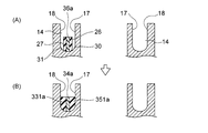
- FIG. 11 is a schematic view showing a state in which the cylinder bore wall heat insulator 36a is installed in the cylinder block 11 shown in FIG. 1, and FIG. 11 (A) is an end view taken along the line ZZ in FIG. It is a figure which shows a mode before a thermal expansion rubber expand
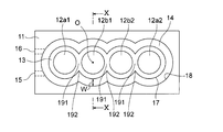
- an open deck type cylinder block 11 of a vehicle-mounted internal combustion engine in which a cylinder bore wall heat insulator is installed is provided with a bore 12 for moving a piston up and down and a cooling water flow.
- the groove-shaped cooling water flow path 14 is formed.
- a wall that separates the bore 12 and the grooved coolant flow path 14 is a cylinder bore wall 13.
- the cylinder block 11 is formed with a cooling water supply port 15 for supplying cooling water to the grooved cooling water flow channel 11 and a cooling water discharge port 16 for discharging cooling water from the grooved cooling water flow channel 11. ing.
- the cylinder block 11 is formed so that two or more bores 12 are arranged in series. Therefore, the bore 12 has end bores 12a1 and 12a2 adjacent to one bore and intermediate bores 12b1 and 12b2 sandwiched between the two bores (note that the number of bores in the cylinder block is two). In the case, only the end bore.) Of the bores arranged in series, the end bores 12a1 and 12a2 are bores at both ends, and the intermediate bores 12b1 and 12b2 are bores between the end bore 12a1 at one end and the end bore 12a2 at the other end.
- a wall between the end bore 12a1 and the intermediate bore 12b1, a wall between the intermediate bore 12b1 and the intermediate bore 12b2, and a wall between the intermediate bore 12b2 and the end bore 12a2 are sandwiched between two bores. Therefore, since heat is transmitted from the two cylinder bores, the wall temperature is higher than other walls. Therefore, in the wall surface 17 on the cylinder bore side of the grooved cooling water flow path 14, the temperature is highest in the vicinity of the inter-bore wall 191. The temperature at the wall boundary 192 and its vicinity is highest.
- the wall surface on the cylinder bore 13 side is referred to as the cylinder bore wall 17 of the grooved cooling water flow path
- the groove shape A wall surface on the opposite side of the cooling water passage from the cylinder bore wall 17 is referred to as a counter wall 18 of the cylinder bore wall.
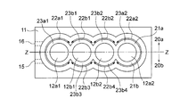
- the half on one side refers to a half on one side when the cylinder block is vertically divided into two in the direction in which the cylinder bores are arranged. Therefore, in the present invention, one half of the bore walls of all cylinder bores refers to one half of the bore wall when the whole cylinder bore wall is vertically divided into two in the direction in which the cylinder bores are arranged.
- the direction in which the cylinder bores are lined up is the ZZ direction
- each of the half walls on one side when the two halves are vertically divided by the ZZ line represents the bore walls of all the cylinder bores. It is a half-bore wall on one side. That is, in FIG.
- the one-side half bore wall 20a from the ZZ line is the one-side half bore wall 21a out of the bore walls of all cylinder bores, and the one-side half 20b from the ZZ line.
- This bore wall is the other half wall bore 21b of the bore walls of all cylinder bores.
- one side of all cylinder bore walls refers to either one half-bore wall 21a or one half-bore wall 21b, and one part refers to a part of one-side half-bore wall 21a or one-side half. A part of the bore wall 21b.
- the bore wall of each cylinder bore refers to each bore wall portion corresponding to each cylinder bore.
- the range indicated by the double arrow 22a1 is the bore wall 23a1 of the cylinder bore 12a1
- the range indicated by the double arrow 22b1 is the bore wall 23b1 of the cylinder bore 12b1
- the range indicated by the double arrow 22b2 is the bore wall 23b2 of the cylinder bore 12b2
- the range indicated by the double arrow 22a2 is the bore wall 23a2 of the cylinder bore 12a2.
- the range indicated by the double arrow 22b3 is the bore wall 23b3 of the cylinder bore 12b1
- the range indicated by the double arrow 22b4 is the bore wall 23b4 of the cylinder bore 12b2.
- a cylinder bore wall heat insulator 36a shown in FIG. 5 is a heat insulator for keeping the one half (20b side) bore wall 21b in FIG.
- a cooling water flow partition member 38 is attached to the heat insulator 36a on the cylinder bore wall. In the cylinder block 11 shown in FIG. 4, the cooling water flow partition member 38 immediately discharges the cooling water supplied from the cooling water supply port 15 to the grooved cooling water channel 14 from the cooling water discharge port 16 in the vicinity.
- the one-half half groove-like cooling water flow path 14 on the 20b side flows toward the end opposite to the position of the cooling water supply port 15, and the one-half half groove-like cooling water flow path 14 on the 20b side
- it goes around the groove-shaped cooling water flow path 14 on one side half on the side of 20 a, and then the groove-shaped cooling water flow path 14 on one side half on the side of 20 a
- It is a member for partitioning between the cooling water supply port 15 and the discharge port 16 so as to flow toward the discharge port 16 and finally to be discharged from the cooling water discharge port 16. Further, in FIG.
- the cooling water that has flowed to the end through the groove-shaped cooling water flow path 14 on one side half of the 20 a side is discharged from the cooling water discharge port 16 formed on the side of the cylinder block 11.
- the cylinder block has been described, for example, the cooling water that has flowed from one end to the other end of the groove-like cooling water passage 14 on one half of the 20a side is discharged from the side of the cylinder block. Instead, there is a cylinder block configured to flow into a cooling water passage formed in the cylinder head.
- the cylinder bore wall heat retaining device 36a is bonded to the inside of the base member 34a, the base member 34a, and is divided into four parts.
- a cylinder bore wall facing member 33a which is attached to the outside of the member 34a and is divided into four parts.
- the cylinder bore wall heat insulator 36a the cylinder bore wall heat retaining member 35a is adhered to the inner surface of the base member 34a by, for example, an adhesive, an adhesive tape, or the like, and the cylinder bore wall opposite wall contact member 33a is stuck to the outer surface of the base member 34a by, for example, an adhesive or an adhesive tape.
- the cylinder bore wall heat retainer 36a is a heat retainer for heat retaining the bore wall 21b on one half of the cylinder block 11 shown in FIG. 4.
- the bore wall 21b on one half of the cylinder block 11 has a bore wall of the cylinder bore 12a1. 23a1, a bore wall 23b3 of the cylinder bore 12b1, a bore wall 23b4 of the cylinder bore 12b2, and a bore wall 23a2 of the cylinder bore 12a2, and a bore wall of each of the four cylinder bores.
- a cylinder bore wall heat retaining member 35a is provided to keep the bore walls of the four cylinder bores warm. Therefore, the cylinder bore wall heat retaining member 36a is provided with four cylinder bore wall heat retaining members 35a.
- the cylinder bore wall heat insulating material is formed on the inner surface of the base member 34a by, for example, an adhesive or an adhesive tape so that the contact surface 26 of the cylinder bore wall heat insulating member 35a faces the cylinder bore wall 17 side.
- the member 35a is stuck.
- an adhesive or an adhesive tape is provided on the outside of the base member 34 such that the contact surface 27 of the wall contact member 33a of the cylinder bore wall faces the wall 18 side of the cylinder bore wall.
- the opposite wall contact member 33a of the cylinder bore wall is stuck by the above.
- the cylinder bore wall heat retaining member 35a and the cylinder bore wall opposite wall contact member 33a are made of heat-expandable rubber.
- This heat-expandable rubber is in a state in which the base foam material is compressed and restrained by a thermoplastic substance before expansion, and is heated to release the restraint by the thermosetting resin, and the state before being compressed, That is, it is a rubber material that expands to an open state. Therefore, the cylinder bore wall heat retaining member 35a is a member for keeping the bore wall of each cylinder bore, and the cylinder bore wall heat retaining member 36a is heated after being installed in the grooved coolant flow path 14 of the cylinder block 11. It expands by.
- the cylinder bore wall heat retaining member 35a expands (heat-sensitive expansion) by heating, so that the contact surface 26 comes into contact with the cylinder bore wall 17 of the grooved cooling water channel 14 and the cylinder bore wall 17 of the grooved cooling water channel 14 Cover the wall.
- the cylinder bore wall facing member 33a expands when the cylinder bore wall heat insulator 36a is installed in the grooved coolant flow path 14 of the cylinder block 11 and then heated. Then, the facing wall contact member 33a of the cylinder bore wall expands by heating (thermal expansion), so that the contact surface 27 comes into contact with the facing wall 18 of the cylinder bore wall of the grooved coolant channel 14.
- the cylinder bore wall heat retaining member 35a is pressed against the cylinder bore wall 17 and the cylinder wall contact member 33a is pressed against the wall 18 of the cylinder bore wall by the elastic force of the heat-expandable rubber after expansion. With such an action, the cylinder bore wall heat insulator 36a is held in the grooved coolant flow path 14. Further, since the cylinder bore wall heat retaining member 35a is in close contact with the cylinder bore wall 17 and covers the cylinder bore wall 17, the cylinder bore wall 17 is kept warm by the cylinder bore wall heat retaining member 35a.
- the base member 34 a is formed into a shape in which four arcs are continuous when viewed from above, and the shape of the base member 34 a is a shape along one half of the grooved coolant flow path 14.
- the base member 34a is a member on which the cylinder bore wall heat retaining member 35a is fixed on the inner side, and the opposite wall contact member 33a on the cylinder bore wall is fixed on the outer side.
- the support portion 34a is a synthetic resin molded body.
- the heat insulator 36a on the cylinder bore wall is installed, for example, in the grooved coolant flow path 14 of the cylinder block 11 shown in FIG. As shown in FIG. 9, the cylinder bore wall heat insulator 36a is inserted into the grooved cooling water channel 14 of the cylinder block 11, and the cylinder bore wall heat insulator 36a is inserted into the grooved cooling water channel as shown in FIG. 14 is installed.
- the cylinder bore wall heat insulator 36a is inserted into the grooved cooling water flow path 14
- the cylinder bore wall heat retaining member 35a and the cylinder bore wall facing wall contact member 33a have not yet expanded.
- the sum of the width, that is, the thickness of the cylinder bore wall heat retaining member 35a, the thickness of the base member 34a, and the thickness of the opposite wall contact member 33a of the cylinder bore wall is smaller than the channel width of the grooved coolant channel 14. Therefore, when the cylinder bore wall heat insulator 36a is inserted into the groove-shaped cooling water flow path 14, the contact surface 26 of the cylinder bore wall heat retaining member 35a does not contact the cylinder bore wall 17, and the cylinder bore wall contacts the wall. The contact surface 27 of the member 33a does not contact the opposite wall 18 of the cylinder bore wall.
- the cylinder bore wall heat retaining device of the present invention is installed in a groove-like cooling water flow path of a cylinder block of an internal combustion engine having a cylinder bore, and keeps all of the bore walls of all cylinder bores or a part of the bore walls of all cylinder bores.
- the warmer of the A base member made of a synthetic resin and having a shape along the shape of the groove-shaped cooling water flow path at the installation position of the heat insulator;
- a cylinder bore wall heat insulating member which is formed of a heat-sensitive expansion rubber (before heat-sensitive expansion) and is adhered to the inside of the base body;
- a wall-to-wall contact member of a cylinder bore wall that is formed of a heat-sensitive expansion rubber (before heat-sensitive expansion) and is adhered to the outside of the base body; Having A cylinder bore wall heat insulator characterized by the above.
- the cylinder bore wall heat insulator of the present invention is installed in the grooved coolant flow path of the cylinder block of the internal combustion engine.
- the cylinder block in which the heat insulating device for the cylinder bore wall of the present invention is installed is an open deck type cylinder block in which two or more cylinder bores are formed in series.
- the cylinder block has a cylinder bore composed of two end bores.
- the cylinder block is an open deck type cylinder block in which three or more cylinder bores are arranged in series
- the cylinder block has a cylinder bore composed of two end bores and one or more intermediate bores. ing.
- the bores at both ends are called end bores
- the bores sandwiched between the other cylinder bores are called intermediate bores.
- the position where the heat insulator for the cylinder bore wall of the present invention is installed is a grooved coolant flow path.
- the position corresponding to the middle and lower part of the groove-shaped cooling water flow path of the cylinder bore is a position where the speed of the piston increases, so it is preferable to keep the temperature of the middle and lower part of the groove-shaped cooling water flow path.
- a position 10 near the middle between the uppermost part 9 and the lowermost part 8 of the groove-like cooling water flow path 14 is indicated by a dotted line, but the groove-like cooling water flow path 14 on the lower side from the position 10 near the middle is shown. This portion is referred to as the middle lower portion of the grooved cooling water flow path.
- the middle and lower part of the grooved cooling water flow path does not mean the part below the middle part between the uppermost part and the lowermost part of the grooved cooling water flow path. It means the part.
- the position where the piston speed increases may be a position where it hits the lower part of the grooved coolant flow path of the cylinder bore. In that case, the lower part of the grooved coolant flow path is kept warm. It is preferable. Therefore, the position from the lowermost part of the grooved cooling water flow path to the heat retention by the cylinder bore wall heat-insulating device of the present invention, that is, the position of the upper end of the rubber member in the vertical direction of the grooved cooling water flow path Is appropriately selected.
- the cylinder bore wall heat insulating device of the present invention includes a base member, a cylinder bore wall heat retaining member (before thermal expansion) attached to the inside of the base member, and a cylinder bore wall opposite to the cylinder bore wall attached to the outside of the base member. A contact member (before thermal expansion).
- the cylinder bore wall heat insulation device according to the present invention when viewed in the circumferential direction, retains all of the wall surface of the grooved coolant channel on the cylinder bore side or part of the wall surface of the grooved coolant channel on the cylinder bore side. It is a warmer to do.
- the cylinder bore wall heat insulator of the present invention is a heat insulator for keeping the whole bore wall of all cylinder bores or a part of the bore wall of all cylinder bores when viewed in the circumferential direction.
- a heat insulator for keeping one half of the bore walls of all cylinder bores as in the embodiment shown in FIG. 5
- a heat insulator for keeping a part of one of the bore walls of all the cylinder bores and a heat insulator for keeping the whole bore wall of all the cylinder bores as in the embodiment shown in FIG.
- the half on one side or a part on one side means a half on one side or a part on one side in the circumferential direction of the cylinder bore wall or the grooved coolant flow channel.
- the base member according to the heat insulator for the cylinder bore wall of the present invention is made of synthetic resin. That is, the base member is made of synthetic resin.
- the synthetic resin that forms the base member is not particularly limited as long as it is a synthetic resin that is normally used for a heat insulator or a water jacket spacer on a cylinder bore wall that is installed in a grooved cooling water flow path of a cylinder block of an internal combustion engine. It is selected appropriately.
- the shape of the base member is a shape along the shape of the groove-shaped cooling water flow path, and when viewed from above, the shape is a shape in which arcs are continuously connected over the range in which the cylinder bore wall heat retaining member is provided.
- the cylinder bore wall heat retaining member (before thermal expansion) is provided at a position where the thermal expansion rubber can expand and cover the cylinder bore wall to be kept warm.
- the installation position, shape, and installation range of the cylinder bore wall thermal insulation member are appropriately selected depending on the number of bore walls and the thermal insulation site of each cylinder bore to be kept warm.
- one cylinder bore wall heat retaining member may be provided for each bore wall of each cylinder bore, that is, one for each bore portion of the base member.
- each bore portion of the base member refers to one arc-shaped portion constituting the base member, and refers to a portion facing the bore wall of one cylinder bore.
- the opposite wall contact member (before thermal expansion) of the cylinder bore wall is provided on the base member on the side opposite to the side on which the cylinder bore wall heat insulating member is provided. .
- the wall contact member of the cylinder bore wall is thermally expanded together with the cylinder bore wall contact member, thereby generating a force that pushes the cylinder bore wall and the wall of the cylinder bore wall (the elastic force of the thermally expanded rubber after expansion).
- the cylinder bore wall heat insulator of the present invention is held in the grooved cooling water flow path, so that the installation position, shape, and installation range of the opposed wall contact member of the cylinder bore wall are such that such a force is generated. It is selected appropriately.
- each bore wall of each cylinder bore so that the opposite wall contact member of the cylinder bore wall is paired with the cylinder bore wall heat retaining member with the base member interposed therebetween. That is, one may be provided for each bore portion of the base member. Further, a cylinder wall contact member may be provided across the bore walls of the two or more cylinder bores, that is, the cylinder bore wall having a shape connected to two or more of the respective bore portions of the base member.
- the cylinder bore wall heat retaining member (before thermal expansion) and the wall contact member of the cylinder bore wall (before thermal expansion) are formed of a compressed thermal expansion rubber.
- Thermally-expandable rubber compressed state
- Examples of the heat-sensitive expansion rubber include heat-sensitive expansion rubber described in JP-A-2004-143262.
- Examples of the base foam material relating to the heat-expandable rubber include various polymer materials such as rubber, elastomer, thermoplastic resin, and thermosetting resin.
- natural rubber, chloropropylene rubber, styrene butadiene rubber, nitrile Examples include butadiene rubber, ethylene propylene diene terpolymer, various synthetic rubbers such as silicone rubber, fluoro rubber, and acrylic rubber, various elastomers such as soft urethane, various thermosetting resins such as hard urethane, phenol resin, and melamine resin. It is done.
- thermoplastic material related to the heat-expandable rubber those having any of glass transition point, melting point or softening temperature of less than 120 ° C are preferable.
- Thermoplastic materials related to heat-expandable rubber include polyethylene, polypropylene, polystyrene, polyvinyl chloride, polyvinylidene chloride, polyvinyl acetate, polyacrylate ester, styrene butadiene copolymer, chlorinated polyethylene, polyvinylidene fluoride, ethylene acetate Vinyl copolymer, ethylene vinyl acetate vinyl chloride acrylic ester copolymer, ethylene vinyl acetate acrylic ester copolymer, ethylene vinyl acetate vinyl chloride copolymer, nylon, acrylonitrile butadiene copolymer, polyacrylonitrile, polyvinyl chloride , Polychloroprene, polybutadiene, thermoplastic polyimide, polyacetal, polyphenylene sulfide, poly
- the cylinder bore wall heat insulating member is adhered to the inner surface of the base member by an adhesive, an adhesive tape, an adhesive, etc., and the opposite wall contact member of the cylinder bore wall is It is stuck to the outer surface of the base member with an adhesive, an adhesive tape, an adhesive or the like.
- the inner side of the base member refers to the side that becomes the cylinder bore wall side when installed in the grooved cooling water flow path
- the outer side of the base member refers to the inner side of the grooved cooling water flow path. When it is installed, it refers to the side of the cylinder bore wall that faces the wall.
- the means for adhering the cylinder bore wall heat retaining member and the cylinder wall facing wall contact member to the base member is not particularly limited and is appropriately selected.
- the cylinder bore wall using an adhesive, an adhesive tape, an adhesive, etc. A method of sticking the wall heat retaining member and the wall contact member of the cylinder bore wall to the base member is exemplified.
- the cylinder bore wall heat insulating device of the present invention after expansion of the thermal expansion rubber, the cylinder bore wall thermal insulation member and the opposite wall contact member of the cylinder bore wall are pressed against the base member by the elastic force of the thermal expansion rubber after expansion. Even if the adhesive strength of the adhesive, adhesive tape, adhesive, etc. is not strong, the cylinder bore wall heat insulating member and the opposite wall contact member of the cylinder bore wall are adhered to the base member with adhesive, adhesive tape, adhesive, etc. Difficult to shift from position.
- the adhesive force such as adhesive, adhesive tape, adhesive, etc. is applied until the heat insulating device of the cylinder bore wall of the present invention is inserted into the grooved cooling water flow path.
- the adhesive force may be such that the cylinder bore wall heat retaining member and the opposed wall contact member of the cylinder bore wall are not peeled off from the surface of the base member.
- the thickness of the cylinder bore wall heat retaining member before thermal expansion (t i -IN ), the thickness of the base member (t x ), and the thickness of the cylinder bore wall before the thermal expansion of the wall contact member ( The total of t i-OUT ) is less than the channel width (w) of the grooved coolant channel in which the cylinder bore wall heat insulator of the present invention is installed. That is, “(t i ⁇ IN + t x + t i ⁇ OUT ) ⁇ w”.
- (t i ⁇ IN + t x + t i ⁇ OUT ) is appropriately selected within the range of “(t i ⁇ IN + t x + t i ⁇ OUT ) ⁇ w”.
- the thickness (t i-IN ) of the cylinder bore wall heat retaining member before thermal expansion is defined as the thermal expansion rubber being restrained in a compressed state by a thermoplastic substance as shown in FIG.
- the thickness of the thermal expansion rubber at the time that is, the thickness of the cylinder bore wall heat retaining member before the thermal expansion
- the thickness before the thermal expansion of the wall contact member of the cylinder bore wall (ti -OUT ) is the thermal expansion rubber Is the thickness of the heat-expandable rubber when it is restrained in a compressed state by the thermoplastic material, that is, the thickness of the wall contact member of the cylinder bore wall before the heat-sensitive expansion.
- the thickness (t x ) of the base member is the thickness of the base member as shown in FIG.
- FIG. 14A is an end view when the heat insulator 36a on the cylinder bore wall is cut along the YY line in FIG.
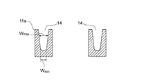
- the channel width (w) of the groove-shaped cooling water channel is a cross section (for example, in FIG. 1) when the cylinder block is cut along a plane passing through the center line O of the cylinder bore, as shown in FIGS. Then, it is the width of the groove-shaped cooling water flow path 14 in the XX cross section. Further, as in the cylinder block 11a shown in FIG. 15, when the groove-like cooling water passage is viewed in the vertical direction, if the passage width is different, the cylinder bore of the present invention is placed in the groove-like cooling water passage. The relationship between the total of t i-IN , t x, and t i-OUT and w is determined at each of the vertical positions after the wall heat insulator is installed.
- the compression ratio of the cylinder bore wall heat retaining member before thermal expansion that is, the thickness of the cylinder bore wall heat retaining member before thermal expansion relative to the open thickness (t 0 -IN ) of the cylinder bore wall heat retaining member.
- the ratio of (t i-IN ) ((t i-IN / t 0-IN ) ⁇ 100) is preferably 6 to 87%, particularly preferably 17 to 46%.
- the compression ratio of the cylinder bore wall heat retaining member before the thermal expansion of the wall contact member that is, the thickness (t 0 -OUT ) of the cylinder bore wall facing wall contact member in the open state.
- the ratio ((ti -OUT / t0 -OUT ) x 100) of the thickness (t i-OUT ) of the cylinder bore wall to the wall contact member before thermal expansion is preferably 6 to 87%, particularly preferably 17 to 46%.
- the thickness (t 0 -IN ) of the cylinder bore wall thermal insulation member is not limited as shown in FIG. 14B because the thermal expansion rubber is unconstrained by the thermoplastic material.
- Thickness after expansion of the heat-sensitive expansion rubber when expanded in an open state without being subjected to heat means a heat-expandable rubber when the heat-expandable rubber expands in an open state without any restriction as shown in FIG. 14 (B). , That is, the thickness of the opposite wall contact member 332a of the cylinder bore wall in the open state.
- FIG. 14 (B) shows a state after the cylinder bore wall heat retaining member 35a and the cylinder wall contact member 33a shown in FIG. 14 (A) are expanded in an open state where the expansion is not restricted at all.
- FIG. 14 (B) shows a state after the cylinder bore wall heat retaining member 35a and the cylinder wall contact member 33a shown in FIG. 14 (A) are expanded in an open state where the expansion is not restricted at all.
- the cylinder bore wall heat insulating member and the opposite wall contact member of the cylinder bore wall are bonded to the synthetic resin base member with an adhesive, an adhesive tape, an adhesive, or the like. Therefore, the heat insulating device for the cylinder bore wall according to the present invention is easily manufactured as compared with the case where the heat insulating device is manufactured by fixing the heat insulating member to the base member made of metal.
- the adhesive force when the cylinder bore wall heat retaining member and the cylinder wall contact member are bonded to the base member with an adhesive, adhesive tape, adhesive, etc. is the same as that between the cylinder wall heat retaining member and the cylinder bore wall. It is weaker than the fixing force when the wall contact member is fixed by bending the bent portion of the metal fixing member. Further, the cylinder bore wall heat retaining member and the cylinder bore generated by the restoring force of the heat sensitive expansion rubber are expanded by expanding the cylinder bore wall heat retaining member formed of the heat sensitive expansion rubber and the wall contact member of the cylinder bore wall in the grooved cooling water flow path.
- the force by which the wall-to-wall contact member presses the cylinder bore wall and the wall of the cylinder bore wall is weaker than the urging force of a metal elastic member such as a metal leaf spring.
- the base member is formed of a synthetic resin that is lighter than the metal material, so that the cylinder wall heat insulating member and the counter wall contact member of the cylinder bore wall are provided in the grooved cooling water flow path.
- the base member when the base member is made of a metal material, the base member is heavy. Therefore, the cylinder bore wall heat insulator can be obtained only by the elastic force of the expanded heat-sensitive rubber and the adhesive force of an adhesive, adhesive tape, adhesive, etc. Cannot be prevented from deviating from the installation position in the groove-shaped cooling water flow path, and the cylinder wall heat retaining member and the wall contact member of the cylinder bore wall from deviating from the attachment position to the base member. Since the adhesive force with respect to a metal material such as an adhesive, an adhesive tape, and an adhesive is weaker than the adhesive force with respect to a synthetic resin, it is difficult to prevent the above-described displacement.
- the cylinder bore wall heat retaining device of the present invention has a recess for preventing displacement of the cylinder bore wall heat retaining member formed on the inner surface of the base member, and the cylinder bore wall heat retaining member covers the recess.
- the cylinder bore wall heat retaining member and the wall contact member of the cylinder bore wall are preferable in that they are unlikely to be displaced from the attachment position to the base member.
- the cylinder bore wall heat insulating device of the present invention is formed with a recess for preventing the displacement of the cylinder wall contact member on the outer surface of the base member, and the wall contact member of the cylinder bore wall is provided with the wall contact member of the cylinder bore wall.
- Covering the recess is preferable in that the cylinder bore wall heat retaining member and the opposite wall contact member of the cylinder bore wall are less likely to be displaced from the attachment position to the base member in the grooved cooling water flow path.
- the recesses for preventing displacement of the cylinder bore wall heat retaining member and the recesses for preventing displacement of the cylinder wall contact member on the cylinder bore wall are expanded in the state where the thermal expansion rubber is expanded in the grooved cooling water flow path.
- the cylinder bore wall heat retaining member and the opposite wall contact member of the cylinder bore wall bite into the cylinder bore wall heat retaining member from the concave portion for preventing displacement of the cylinder bore wall heat retaining member and the concave portion for preventing displacement of the wall contact member of the cylinder bore wall.
- the opposite wall contact member of the cylinder bore wall is difficult to be displaced from the fixing position of the base member.
- the shape of the recess for preventing misalignment is not particularly limited, and examples thereof include a circular recess, a rectangular recess, and a circular or rectangular through hole. The formation position and number of the recesses for preventing misalignment are appropriately selected.
- the cylinder bore wall heat insulator of the present invention can have a cooling water flow partition member on one end side as in the embodiment shown in FIG. Further, the cylinder bore wall heat insulating device of the present invention is provided with a member for preventing the entire heat insulating device from shifting upward in the support portion, for example, on the upper side of both sides of the support portion, and the upper end is a cylinder head or a cylinder. A cylinder head abutting member that abuts the head gasket can be provided. In addition, the cylinder bore wall heat insulator of the present invention may have other members for adjusting the flow of the cooling water.
- the cylinder bore wall heat insulator 36a shown in FIG. 5 is a heat insulator for keeping the bore wall of one half of all the cylinder bore walls of the cylinder block 11 shown in FIG. 4, but as the cylinder bore wall heat insulator of the present invention.
- a cylinder bore wall heat insulator 36b shown in FIG. 12 is a heat retainer for heat insulation of a part of the bore wall 21a on one half of the cylinder block 11 shown in FIG. 4, that is, the bore walls of the cylinder bores 12b1 and 12b2.
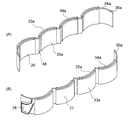
- FIG. 12 is a schematic perspective view of a form example of a cylinder bore wall heat insulator according to the present invention
- FIG. 12 (A) is a perspective view seen from diagonally inside
- FIG. 12 (B) is an outer side. It is the perspective view seen from diagonally upward.
- the cylinder bore wall heat insulator of the present invention includes a heat retainer for heat insulation of all the bore walls of all the cylinder bores as in the embodiment shown in FIG.
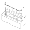
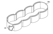
- a cylinder bore wall heat insulator 36c shown in FIG. 13 is a heat insulator for keeping all the bore walls of all the cylinder bores of the cylinder block 11 shown in FIG.
- the cylinder bore wall heat retaining device of the present invention may be a heat retaining device for all of the bore walls of all the cylinder bores of the cylinder block, or a part of the bore walls of all the cylinder bores of the cylinder block, for example, One side half or a part of one side of the warmer for warming may be used.
- FIG. 13 is a schematic perspective view of a form example of a cylinder bore wall heat insulator according to the present invention.
- a cylinder bore wall heat insulator that is not provided with a heat retaining member on the bottom side of the base member, such as the cylinder bore wall heat retainer 36 a shown in FIG. 5, is installed in the grooved cooling water flow path of the cylinder block.
- a heat insulating member made of heat-expandable rubber is disposed on the bottom side of the base member as the cylinder bore wall heat insulating device of the present invention. There is a warmer.
- a heat retaining member is also disposed on the bottom side of the base member 34b. As shown in FIG.
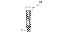
- the cylinder bore wall heat insulator 36d is made of a heat-sensitive expansion rubber and has a vertical length that is longer than the base member 34b.
- a cylinder wall facing member 33b having a cylinder bore wall longer than the base member 34b is prepared, and then the heat retaining member 35b of the cylinder bore wall and the bottom side of the counter wall contacting member 33b of the cylinder bore wall protrude from the bottom of the base member 34b
- the base member 34b is bonded with the heat retaining member 35b of the cylinder bore wall and the opposite wall contact member 33b of the cylinder bore wall, and then the lower inner surface 353b of the heat retaining member 35b of the cylinder bore wall and the lower portion of the lower wall contact member 33b of the cylinder bore wall.
- the side surface 333b is attached to the bottom surface 343b of the base member 34b, and the bottom surface 343b of the base member 34b is attached. Covering, further, it is prepared by attaching the lower inner surface 333b of the pair walls contact member 33b of the lower inner surface 353b and the cylinder bore wall of the heat insulating member 35b of the cylinder bore wall. At this time, in FIG.
- the lower inner side surface 353b of the heat retaining member 35b on the cylinder bore wall and the lower inner side surface 333b of the opposite wall contact member 33b on the cylinder bore wall are adhered to the bottom surface 343b of the base member 34b,
- the base member 34b A bottom-side heat retaining portion 39 made of a heat-sensitive expansion rubber is formed on the bottom side of the base plate.
- FIG. 18 shows a state in which the cylinder bore wall heat insulator 36d is installed in the cylinder block 11b.
- the cylinder bore wall heat insulator 36d is arranged so that the bottom side heat retaining portion 39 of the cylinder bore wall heat insulator 36d is in contact with the bottom of the grooved coolant flow path 14b of the cylinder block 11b. It is installed in the groove-like cooling water flow path 14b of the block 11b.
- the thermal expansion rubber is heated after the cylinder bore wall heat insulator 36d is installed in the grooved cooling water flow path 14b, as shown in FIG. 18B, the cylinder bore wall heat retaining member 35b becomes the cylinder bore wall.
- the opposite wall contact member 33b of the cylinder bore wall expands until it comes into contact with the opposite wall 18b of the cylinder bore wall, and the bottom side heat retaining portion 39 comes into contact with the entire bottom surface of the grooved cooling water flow path 14b. Expands to In the cylinder block, heat escapes from the bottom side of the groove-like cooling water flow path (the portion indicated by reference numeral 111 in FIG. 18B), so that the bottom side of the base member, like the heat retaining device 36d on the cylinder bore wall, is used. In addition, since the heat retaining member made of the heat-sensitive expansion rubber is disposed, the heat retaining property of the cylinder bore wall is enhanced.
- the bottom side of the groove-shaped cooling water flow path of the cylinder block is often curved as in the embodiment shown in FIG. 18, and in such a case, the heat-sensitive expansion rubber is also provided on the bottom side of the base member.
- FIG. 16 is a schematic view showing a cross section of a cylinder bore wall heat insulator 36d, which is an example of a cylinder bore wall heat insulator according to the present invention.
- FIG. 17 is a schematic diagram showing how the cylinder bore wall heat insulator 36d shown in FIG. 16 is produced.
- FIG. 18 is a cross-sectional view showing a state where the cylinder bore wall heat insulator 36d shown in FIG. 16 is installed in the groove-shaped cooling water flow path.
- the internal combustion engine of the present invention has a cylinder block in which a grooved cooling water flow path is formed,
- the cylinder bore wall heat insulator of the present invention is installed in the grooved cooling water flow path,
- the cylinder block according to the internal combustion engine of the present invention is the same as the cylinder block according to the heat insulator for the cylinder bore wall according to the present invention.
- the internal combustion engine of the present invention includes a cylinder head, a camshaft, a valve, a piston, a connecting rod, and a crankshaft in addition to the cylinder block and the cylinder bore wall heat retaining device of the present invention installed in the grooved coolant flow path. .
- the cylinder bore wall heat retaining device of the present invention is displaced from the installation position in the grooved cooling water flow path, and the cylinder bore wall heat retaining member and the opposite wall contact member of the cylinder bore wall are bonded to the base member, This is preferable in that the effect of preventing displacement from the position attached by an adhesive tape, an adhesive, or the like is enhanced.
- the flow width at the position where the flow passage width is the largest among the vertical positions occupied by the heat insulator of the cylinder bore wall of the invention is w max and the flow passage width is the largest.
- Equation (1) (w ⁇ t x ) is the thickness (t a ⁇ IN ) of the cylinder bore wall heat retaining member after the thermal expansion in the grooved cooling water flow path and the thermal expansion in the grooved cooling water flow path This corresponds to the total thickness of the wall contact members of the cylinder bore wall (ta -OUT ).
- the formula (1) is expressed by the following formula (2): ((T a ⁇ IN + t a ⁇ OUT ) / (t 0 ⁇ IN + t 0 ⁇ OUT )) ⁇ 100 (2)
- t a-IN is the thickness of the cylinder bore wall heat retaining member after expansion in the grooved cooling water channel
- t a-OUT is the cylinder bore wall after expansion in the grooved cooling water channel
- T 0 -IN is the thickness of the cylinder bore wall heat retaining member in the open state
- t 0 -OUT is the thickness of the cylinder wall in the open state of the wall contact member.
- Formula (2) shows how much the cylinder bore wall heat retaining member after expansion and the opposite wall contact member of the cylinder bore wall are compressed in the grooved coolant flow path of the cylinder block of the internal combustion engine of the present invention. . That is, Formula (2) is equivalent to the compression rate (%) of the heat-expandable rubber after expansion in the grooved cooling water flow path. Therefore, the value represented by the formula (2) is preferably 17 to 75%, particularly preferably 20 to 40%, and the expansion that forms the cylinder bore wall heat retaining member and the wall contact member of the cylinder bore wall after the expansion is performed.
- the cylinder bore wall heat retaining device of the present invention is displaced from the installation position in the grooved cooling water flow path, and the cylinder bore wall heat retaining member and the cylinder bore wall facing wall contact member are This is preferable in that the effect of preventing the base member from being displaced from the position fixed to the base member with an adhesive, an adhesive tape, an adhesive, or the like is enhanced.
- the thickness (ta -IN ) of the cylinder bore wall heat retaining member after thermal expansion in the grooved cooling water channel is defined in the grooved cooling water channel as shown in FIG.
- the thickness after expansion of the heat-sensitive expansion rubber after expansion that is, the thickness of the cylinder bore wall heat retaining member 351a after thermal expansion in the groove-shaped cooling water flow path, and after the heat-sensitive expansion in the groove-shaped cooling water flow path
- the thickness (ta -OUT ) of the opposite wall contact member of the cylinder bore wall is the thickness after expansion of the thermal expansion rubber after expansion in the grooved cooling water flow path, that is, The thickness of the opposite wall contact member 331a of the cylinder bore wall after the thermal expansion in the grooved cooling water flow path.
- FIG. 14C is a view showing a state after the cylinder bore wall heat retaining member 35a and the cylinder wall facing wall contact member 33a shown in FIG. 14A are thermally expanded in the grooved coolant flow path of the cylinder block 11. It is.
- the automobile of the present invention is an automobile having the internal combustion engine of the present invention.
- a cylinder bore wall heat insulator that has high adhesion to the wall surface on the cylinder bore side of the grooved cooling water flow path of the cylinder block and is less likely to be displaced in the grooved cooling water flow path by a simple manufacturing process. Since it can be manufactured, it is possible to provide a heat insulator for the cylinder bore wall that has high adhesion to the wall surface on the cylinder bore side of the grooved cooling water flow path of the cylinder block and is less likely to be displaced in the grooved cooling water flow path.
Abstract
The present invention provides a heat retention tool installed in a groove-shaped cooling water flow channel of a cylinder block in an internal combustion engine having a cylinder bore, the purpose of the heat retention tool being to retain heat in all of a bore wall of the entire cylinder bore or in part of the bore wall of the entire cylinder bore, and the heat retention tool for a cylinder bore wall being characterized by having: a base member that is made of a synthetic resin and has a shape conforming to the shape of the groove-shaped cooling water flow channel at the position where the heat retention tool is installed; a cylinder bore wall heat retention member that is formed from a heat-sensitive expanding rubber and is fixed to the inner side of the base part; and an opposing-wall contact member of the cylinder bore wall, the opposing-wall contact member being formed from a heat-sensitive expanding rubber and being fixed to the outer side of the base part. According to the present invention, it is possible to provide a heat retention tool that adheres well to the cylinder-bore-side wall surface of the groove-shaped cooling water flow channel, does not readily cause positional misalignment within the groove-shaped cooling water flow channel, and has a simple structure.
Description
本発明は、内燃機関のシリンダブロックのシリンダボア壁の溝状冷却水流路側の壁面に接触させて配置される保温具及びそれを備える内燃機関並びに該内燃機関を有する自動車に関する。
The present invention relates to a heat insulator arranged in contact with a wall surface on the grooved coolant flow path side of a cylinder bore wall of a cylinder block of an internal combustion engine, an internal combustion engine including the same, and an automobile having the internal combustion engine.
内燃機関では、ボア内のピストンの上死点で燃料の爆発が起こり、その爆発によりピストンが押し下げられるという構造上、シリンダボア壁の上側は温度が高くなり、下側は温度が低くなる。そのため、シリンダボア壁の上側と下側では、熱変形量に違いが生じ、上側は大きく膨張し、一方、下側の膨張が小さくなる。
In the internal combustion engine, fuel explosion occurs at the top dead center of the piston in the bore, and the piston is pushed down by the explosion, so that the temperature is higher on the upper side of the cylinder bore wall and the temperature is lower on the lower side. Therefore, there is a difference in the amount of thermal deformation between the upper side and the lower side of the cylinder bore wall, and the upper side expands greatly, while the lower side expansion decreases.
その結果、ピストンのシリンダボア壁との摩擦抵抗が大きくなり、これが、燃費を下げる要因となっているので、シリンダボア壁の上側と下側とで熱変形量の違いを少なくすることが求められている。
As a result, the frictional resistance with the cylinder bore wall of the piston increases, and this is a factor that lowers fuel consumption. Therefore, it is required to reduce the difference in thermal deformation between the upper side and the lower side of the cylinder bore wall. .
そこで、従来より、シリンダボア壁の壁温を均一にするために、溝状冷却水流路内にスペーサーを設置し、溝状冷却水流路内の冷却水の水流を調節して、冷却水によるシリンダボア壁の上側の冷却効率と及び下側の冷却効率を制御することが試みられてきた。例えば、特許文献1には、内燃機関のシリンダブロックに形成された溝状冷却用熱媒体流路内に配置されることで溝状冷却用熱媒体流路内を複数の流路に区画する流路区画部材であって、前記溝状冷却用熱媒体流路の深さに満たない高さに形成され、前記溝状冷却用熱媒体流路内をボア側流路と反ボア側流路とに分割する壁部となる流路分割部材と、前記流路分割部材から前記溝状冷却用熱媒体流路の開口部方向に向けて形成され、かつ先端縁部が前記溝状冷却用熱媒体流路の一方の内面を越えた形に可撓性材料で形成されていることにより、前記溝状冷却用熱媒体流路内への挿入完了後は自身の撓み復元力により前記先端縁部が前記内面に対して前記溝状冷却用熱媒体流路の深さ方向の中間位置にて接触することで前記ボア側流路と前記反ボア側流路とを分離する可撓性リップ部材と、を備えたことを特徴とする内燃機関冷却用熱媒体流路区画部材が開示されている。
Therefore, conventionally, in order to make the wall temperature of the cylinder bore wall uniform, a spacer is installed in the grooved cooling water flow path, and the flow of the cooling water in the grooved cooling water flow path is adjusted so that the cylinder bore wall caused by the cooling water Attempts have been made to control the cooling efficiency on the upper side and the cooling efficiency on the lower side. For example, Patent Document 1 discloses a flow that divides a groove-shaped cooling heat medium flow path into a plurality of flow paths by being disposed in a groove-shaped cooling heat medium flow path formed in a cylinder block of an internal combustion engine. A channel partition member formed at a height less than a depth of the groove-shaped cooling heat medium flow path, and a bore-side flow path and an anti-bore-side flow path in the groove-shaped cooling heat medium flow path A flow path dividing member serving as a wall portion that is divided into a groove portion, a groove portion that is formed from the flow path dividing member toward the opening of the groove-shaped cooling heat medium flow channel, and a leading edge is the groove-shaped cooling heat medium. By being formed of a flexible material so as to extend beyond one inner surface of the flow path, the end edge portion is caused by its own bending restoring force after completion of insertion into the grooved cooling heat medium flow path. By contacting the inner surface at the intermediate position in the depth direction of the grooved cooling heat medium flow path, A flexible lip member that separates the A-side passage, the internal combustion engine cooling heat medium flow passage partition member comprising the disclosed.
ところが、引用文献1の内燃機関冷却用熱媒体流路区画部材によれば、ある程度のシリンダボア壁の壁温の均一化が図れるので、シリンダボア壁の上側と下側との熱変形量の違いを少なくすることができるものの、近年、更に、シリンダボア壁の上側と下側とで熱変形量の違いを少なくすることが求められている。
However, according to the heat medium flow path partition member for cooling the internal combustion engine of the cited document 1, the wall temperature of the cylinder bore wall can be made uniform to some extent, so that the difference in the amount of thermal deformation between the upper side and the lower side of the cylinder bore wall is reduced. In recent years, however, it has been demanded to further reduce the difference in thermal deformation between the upper side and the lower side of the cylinder bore wall.
そのようなことから、近年は、シリンダブロックの溝状冷却水流路の中下部のシリンダボア側の壁面を保温具で積極的に保温することにより、シリンダボア壁の壁温の均一化が図られている。そして、溝状冷却水流路の中下部のシリンダボア側の壁面を効果的に保温するためには、保温具の溝状冷却水流路の中下部のシリンダボア側の壁面への密着性が高いことが求められている。
For this reason, in recent years, the wall temperature of the cylinder bore wall has been made uniform by actively keeping the wall surface on the cylinder bore side in the middle and lower part of the groove-shaped cooling water flow path of the cylinder block with a heat insulator. . In order to effectively keep the wall surface on the cylinder bore side in the middle and lower part of the grooved cooling water flow path, it is required that the heat insulator has high adhesion to the wall surface on the cylinder bore side in the middle and lower part of the grooved cooling water flow path. It has been.
また、近年は、シリンダボア側の壁面のうち、特定の部分を選択的に保温したとの要求が高まっている。そのような要求に対しては、シリンダボア側の壁面の周方向の全部を保温する全周タイプの保温具ではなく、周方向の一部を保温する部分タイプの保温具が必要となる。ところが、部分タイプの保温具は、全周タイプの保温具に比べ、溝状冷却水流路内で位置ずれを起こし易いという問題がある。また、全周タイプの保温具も、部分タイプに比べれば、位置ずれを起こし難いものの、全く位置ずれを起こさないわけではない。
In recent years, there is an increasing demand for selectively keeping a specific part of the wall surface on the cylinder bore side. In order to meet such demands, a partial type heat insulator that retains a part of the circumferential direction is required instead of an all-round type heat retainer that retains the entire circumferential direction of the wall surface on the cylinder bore side. However, the partial type heat insulator has a problem that it is liable to be displaced in the grooved coolant flow channel as compared with the all-around type heat insulator. In addition, the all-around type heat insulator is less likely to cause a positional shift than the partial type, but does not cause a positional shift at all.
また、保温具において、保温部材が固定される基体部材が、金属製の場合には、保温部材及び基体部材の加工及び組み立てが複雑になる。そのため、製造が簡便な保温具が求められている。
Further, in the heat retaining device, when the base member to which the heat retaining member is fixed is made of metal, processing and assembly of the heat retaining member and the base member are complicated. Therefore, there is a need for a heat insulator that is easy to manufacture.
従って、本発明の課題は、溝状冷却水流路のシリンダボア側の壁面への密着性が高く、溝状冷却水流路内で位置ずれを起こし難く、製造が簡便な保温具を提供することにある。
Accordingly, an object of the present invention is to provide a heat insulator that has high adhesion to the wall surface on the cylinder bore side of the grooved cooling water flow path, hardly causes displacement in the grooved cooling water flow path, and is easy to manufacture. .
上記課題は、以下の本発明により解決される。すなわち、本発明(1)は、シリンダボアを有する内燃機関のシリンダブロックの溝状冷却水流路に設置され、全シリンダボアのボア壁の全部又は全シリンダボアのボア壁のうちの一部を保温するための保温具であり、
合成樹脂製であり、該保温具の設置位置の該溝状冷却水流路の形状に沿う形状を有する基体部材と、
感熱膨張ゴムで形成されており、且つ、該基体部の内側に貼着されているシリンダボア壁保温部材と、
感熱膨張ゴムで形成されており、且つ、該基体部の外側に貼着されているシリンダボア壁の対壁接触部材と、
を有すること、
を特徴とするシリンダボア壁の保温具を提供するものである。 The above problems are solved by the present invention described below. That is, the present invention (1) is installed in the groove-like cooling water flow path of the cylinder block of the internal combustion engine having the cylinder bore, and keeps all the bore walls of all the cylinder bores or a part of the bore walls of all the cylinder bores. A warmer,
A base member made of a synthetic resin and having a shape along the shape of the groove-shaped cooling water flow path at the installation position of the heat insulator;
A cylinder bore wall heat insulating member that is formed of a heat-sensitive expansion rubber and is adhered to the inside of the base body;
A wall-to-wall contact member of a cylinder bore wall that is formed of heat-sensitive expansion rubber and is adhered to the outside of the base body;
Having
A cylinder bore wall heat insulating device is provided.
また、本発明(2)は、前記シリンダボア壁保温部材を形成している感熱膨張ゴム及び前記シリンダボア壁の対壁接触部材を形成している感熱膨張ゴムのいずれもが、ベースフォーム材と、熱可塑性物質と、からなり、該ベースフォーム材が、シリコンゴム、フッ素ゴム、天然ゴム、ブタジエンゴム、エチレンプロピレンジエンゴム又はニトリルブタジエンゴムであり、該熱可塑性物質が、樹脂又は金属材料であることを特徴とする(1)のシリンダボア壁の保温具を提供するものである。
Further, in the present invention (2), both the thermal expansion rubber forming the cylinder bore wall heat insulating member and the thermal expansion rubber forming the wall contact member of the cylinder bore wall are made of base foam material, The base foam material is silicon rubber, fluorine rubber, natural rubber, butadiene rubber, ethylene propylene diene rubber or nitrile butadiene rubber, and the thermoplastic material is a resin or a metal material. A cylinder bore wall heat insulator characterized by (1) is provided.
また、本発明(3)は、前記シリンダボア壁保温部材の開放状態の厚み(t0-IN)に対する前記シリンダボア壁保温部材の感熱膨張前の厚み(ti-IN)の割合((ti-IN/t0-IN)×100)、及び前記シリンダボア壁の対壁接触部材の開放状態の厚み(t0-OUT)に対する前記シリンダボア壁の対壁接触部材の感熱膨張前の厚み(ti-OUT)の割合((ti-OUT/t0-OUT)×100)が、いずれも6~87%であることされたものであることを特徴とする(1)又は(2)いずれかのシリンダボア壁の保温具を提供するものである。
In the present invention (3), the ratio of the thickness (t i-IN ) of the cylinder bore wall heat retaining member before thermal expansion to the thickness (t 0 -IN ) of the cylinder bore wall heat retaining member ((t i− IN / t 0−IN ) × 100), and the thickness of the cylinder bore wall facing wall contact member relative to the open thickness (t 0−OUT ) of the cylinder bore wall before the thermal expansion (t i− OUT ) ratio ((t i-OUT / t 0-OUT ) × 100) is determined to be 6 to 87%, either (1) or (2) The present invention provides a heat insulator for a cylinder bore wall.
また、本発明(4)は、前記基体部材の内側の面に、前記シリンダボア壁本部材の位置ずれ防止用の凹部が形成されており、且つ、前記シリンダボア壁保温部材が該凹部を覆っていることを特徴とする(1)~(3)いずれかのシリンダボア壁の保温具を提供するものである。
In the present invention (4), a concave portion for preventing displacement of the cylinder bore wall main member is formed on the inner surface of the base member, and the cylinder bore wall heat retaining member covers the concave portion. (1) to (3) are provided with a heat insulator for the cylinder bore wall.
また、本発明(5)は、前記基体部材の外側の面に、前記シリンダボア壁の対壁接触部材の位置ずれ防止用の凹部が形成されており、前記シリンダボア壁の対壁接触部材が該凹部を覆っていることを特徴とする(1)~(3)いずれかのシリンダボア壁の保温具を提供するものである。
Further, in the present invention (5), a recess for preventing displacement of the wall contact member of the cylinder bore wall is formed on the outer surface of the base member, and the wall contact member of the cylinder bore wall is the recess. (1) to (3) are provided with a heat insulator for the cylinder bore wall.
また、本発明(6)は、前記基体部材の底側にも、感熱膨張ゴムからなる保温部材が配設されていることを特徴とする(1)~(5)いずれかのシリンダボア壁の保温具。
According to the present invention (6), a heat retaining member made of heat-sensitive expansion rubber is also disposed on the bottom side of the base member. (1) to (5) The heat retaining material of any one of the cylinder bore walls Ingredients.
また、本発明(7)は、溝状冷却水流路が形成されているシリンダブロックを有し、
該溝状冷却水流路内に、(1)~(6)いずれかのシリンダボア壁の保温具が設置されていること、
を特徴とする内燃機関を提供するものである。 Moreover, this invention (7) has a cylinder block in which the groove-shaped cooling water flow path is formed,
(1) to (6) any one of the cylinder bore wall heat insulators installed in the grooved cooling water flow path;
An internal combustion engine characterized by the above is provided.
また、本発明(8)は、下記式(1):
((w-tx)/(t0-IN+t0-OUT))×100 (1)
(式(1)中、wは前記溝状冷却水流路の流路幅であり、txは前記基体部材の厚みであり、t0-INは前記シリンダボア壁保温部材の開放状態の厚みであり、t0-OUTは前記シリンダボア壁の対壁接触部材の開放状態の厚みである。)
で表される値が17~75%であることを特徴とする(7)の内燃機関を提供するものである。 Further, the present invention (8) provides the following formula (1):
((W−t x ) / (t 0−IN + t 0−OUT )) × 100 (1)
(Wherein, w is the channel width of the grooved cooling water channel, t x is the thickness of the base member, and t 0-IN is the thickness of the cylinder bore wall heat retaining member in the open state) , T 0-OUT is the thickness of the cylinder wall facing the wall contact member in the open state.)
The internal combustion engine according to (7) is characterized in that the value represented by the formula is 17 to 75%.
また、本発明(9)は、下記式(2):
((ta-IN+ta-OUT)/(t0-IN+t0-OUT))×100 (2)
(式(2)中、ta-INは前記溝状冷却水流路内で膨張した後のシリンダボア壁保温部材の厚みであり、ta-OUTは前記溝状冷却水流路内で膨張した後のシリンダボア壁の対壁接触部材の厚みであり、t0-INは前記シリンダボア壁保温部材の開放状態の厚みであり、t0-OUTは前記シリンダボア壁の対壁接触部材の開放状態の厚みである。)で表される値が17~75%であることを特徴とする(7)の内燃機関を提供するものである。 Further, the present invention (9) provides the following formula (2):
((T a−IN + t a−OUT ) / (t 0−IN + t 0−OUT )) × 100 (2)
(In the formula (2), ta -IN is the thickness of the cylinder bore wall heat retaining member after expansion in the groove-shaped cooling water flow path, and ta -OUT is the value after expansion in the groove-shaped cooling water flow path. The thickness of the cylinder-bore wall facing wall contact member, t 0 -IN is the thickness of the cylinder bore wall heat retaining member in the open state, and t 0 -OUT is the thickness of the cylinder bore wall facing the wall-contact member. The internal combustion engine according to (7) is characterized in that the value represented by.) Is 17 to 75%.
また、本発明(10)は、(7)~(9)いずれかの内燃機関を有することを特徴とする自動車を提供するものである。
Further, the present invention (10) provides an automobile characterized by having any of the internal combustion engines (7) to (9).
本発明によれば、溝状冷却水流路のシリンダボア側の壁面への密着性が高く、溝状冷却水流路内で位置ずれを起こし難く、製造が簡便な保温具を提供することができる。
According to the present invention, it is possible to provide a heat insulator that has high adhesion to the wall surface on the cylinder bore side of the groove-shaped cooling water flow path, hardly causes displacement in the groove-shaped cooling water flow path, and is easy to manufacture.
本発明のシリンダボア壁の保温具及び本発明の内燃機関について、図1~図11を参照して説明する。図1~図4は、本発明のシリンダボア壁の保温具が設置されるシリンダブロックの形態例を示すものであり、図1及び図4は、本発明のシリンダボア壁の保温具が設置されるシリンダブロックを示す模式的な平面図であり、図2は、図1のx-x線断面図であり、図3は、図1に示すシリンダブロックの斜視図である。図5は、本発明のシリンダボア壁の保温具の形態例を示す模式的な斜視図である。図6は、図5中の保温具36aを上から見た図である。図7は、図5中の保温具36aを横から見た図であり、内側から見た図である。図8は、図5中の保温具36aを横から見た図であり、外側から見た図である。図9は、図1に示すシリンダブロック11に、シリンダボア壁の保温具36aが挿入される様子を示す模式図である。図10は、図1に示すシリンダブロック11の溝状冷却水流路14内に、シリンダボア壁の保温具36aを設置した後且つ感熱膨張ゴムが膨張する前の様子を示す模式図である。図11は、図1に示すシリンダブロック11に、シリンダボア壁の保温具36aが設置されている様子を示す模式図であり、(A)は、図10中のZ-Z線端面図であり、感熱膨張ゴムが膨張する前の様子を示す図であり、(B)は、感熱膨張ゴムが膨張した後の様子を示す図である。
Referring to FIGS. 1 to 11, the cylinder bore wall heat insulator of the present invention and the internal combustion engine of the present invention will be described. 1 to 4 show an example of a cylinder block in which a cylinder bore wall heat insulator of the present invention is installed. FIGS. 1 and 4 show a cylinder in which a cylinder bore wall heat insulator of the present invention is installed. FIG. 2 is a schematic plan view showing the block, FIG. 2 is a sectional view taken along line xx of FIG. 1, and FIG. 3 is a perspective view of the cylinder block shown in FIG. FIG. 5 is a schematic perspective view showing an example of a form of a heat insulator for a cylinder bore wall according to the present invention. FIG. 6 is a view of the heat insulator 36a in FIG. 5 as viewed from above. FIG. 7 is a view of the heat insulator 36a in FIG. 5 as viewed from the side, and is a view as viewed from the inside. FIG. 8 is a view of the heat insulator 36a in FIG. 5 as viewed from the side, and is a view as viewed from the outside. FIG. 9 is a schematic view showing a state in which the heat insulator 36a on the cylinder bore wall is inserted into the cylinder block 11 shown in FIG. FIG. 10 is a schematic diagram showing a state after installing the heat insulator 36a on the cylinder bore wall in the groove-like cooling water flow path 14 of the cylinder block 11 shown in FIG. 1 and before the thermal expansion rubber is expanded. FIG. 11 is a schematic view showing a state in which the cylinder bore wall heat insulator 36a is installed in the cylinder block 11 shown in FIG. 1, and FIG. 11 (A) is an end view taken along the line ZZ in FIG. It is a figure which shows a mode before a thermal expansion rubber expand | swells, (B) is a figure which shows a mode after a thermal expansion rubber expand | swells.
図1~図3に示すように、シリンダボア壁の保温具が設置される車両搭載用内燃機関のオープンデッキ型のシリンダブロック11には、ピストンが上下するためのボア12、及び冷却水を流すための溝状冷却水流路14が形成されている。そして、ボア12と溝状冷却水流路14とを区切る壁が、シリンダボア壁13である。また、シリンダブロック11には、溝状冷却水流路11へ冷却水を供給するための冷却水供給口15及び冷却水を溝状冷却水流路11から排出するための冷却水排出口16が形成されている。
As shown in FIGS. 1 to 3, an open deck type cylinder block 11 of a vehicle-mounted internal combustion engine in which a cylinder bore wall heat insulator is installed is provided with a bore 12 for moving a piston up and down and a cooling water flow. The groove-shaped cooling water flow path 14 is formed. A wall that separates the bore 12 and the grooved coolant flow path 14 is a cylinder bore wall 13. Further, the cylinder block 11 is formed with a cooling water supply port 15 for supplying cooling water to the grooved cooling water flow channel 11 and a cooling water discharge port 16 for discharging cooling water from the grooved cooling water flow channel 11. ing.
このシリンダブロック11には、2つ以上のボア12が直列に並ぶように形成されている。そのため、ボア12には、1つのボアに隣り合っている端ボア12a1、12a2と、2つのボアに挟まれている中間ボア12b1、12b2とがある(なお、シリンダブロックのボアの数が2つの場合は、端ボアのみである。)。直列に並んだボアのうち、端ボア12a1、12a2は両端のボアであり、また、中間ボア12b1、12b2は、一端の端ボア12a1と他端の端ボア12a2の間にあるボアである。端ボア12a1と中間ボア12b1の間の壁、中間ボア12b1と中間ボア12b2の間の壁及び中間ボア12b2と端ボア12a2の間の壁(ボア間壁191)は、2つのボアに挟まれる部分なので、2つのシリンダボアから熱が伝わるため、他の壁に比べ壁温が高くなる。そのため、溝状冷却水流路14のシリンダボア側の壁面17では、ボア間壁191の近傍が、温度が最も高くなるので、溝状冷却水流路14のシリンダボア側の壁面17のうち、各シリンダボアのボア壁の境界192及びその近傍の温度が最も高くなる。
The cylinder block 11 is formed so that two or more bores 12 are arranged in series. Therefore, the bore 12 has end bores 12a1 and 12a2 adjacent to one bore and intermediate bores 12b1 and 12b2 sandwiched between the two bores (note that the number of bores in the cylinder block is two). In the case, only the end bore.) Of the bores arranged in series, the end bores 12a1 and 12a2 are bores at both ends, and the intermediate bores 12b1 and 12b2 are bores between the end bore 12a1 at one end and the end bore 12a2 at the other end. A wall between the end bore 12a1 and the intermediate bore 12b1, a wall between the intermediate bore 12b1 and the intermediate bore 12b2, and a wall between the intermediate bore 12b2 and the end bore 12a2 (inter-bore wall 191) are sandwiched between two bores. Therefore, since heat is transmitted from the two cylinder bores, the wall temperature is higher than other walls. Therefore, in the wall surface 17 on the cylinder bore side of the grooved cooling water flow path 14, the temperature is highest in the vicinity of the inter-bore wall 191. The temperature at the wall boundary 192 and its vicinity is highest.
また、本発明では、溝状冷却水流路14の壁面のうち、シリンダボア13側の壁面を、溝状冷却水流路のシリンダボア壁17と記載し、溝状冷却水流路14の壁面のうち、溝状冷却水流路のシリンダボア壁17とは反対側の壁面を、シリンダボア壁の対壁18と記載する。
In the present invention, among the wall surfaces of the grooved cooling water flow path 14, the wall surface on the cylinder bore 13 side is referred to as the cylinder bore wall 17 of the grooved cooling water flow path, and among the wall surfaces of the grooved cooling water flow path 14, the groove shape A wall surface on the opposite side of the cooling water passage from the cylinder bore wall 17 is referred to as a counter wall 18 of the cylinder bore wall.
また、本発明において、片側半分とは、シリンダブロックをシリンダボアが並んでいる方向で垂直に二分割したときの片側の半分を指す。よって、本発明において、全シリンダボアのボア壁のうちの片側半分のボア壁とは、全シリンダボア壁をシリンダボアが並んでいる方向で垂直に二分割したときの片側の半分のボア壁を指す。例えば、図4では、シリンダボアが並んでいる方向がZ-Z方向であり、このZ-Z線で垂直に二分割したときの片側半分のボア壁のそれぞれが、全シリンダボアのボア壁のうちの片側半分のボア壁である。つまり、図4では、Z-Z線より20a側の片側半分のボア壁が、全シリンダボアのボア壁のうちの一方の片側半分のボア壁21aであり、Z-Z線より20b側の片側半分のボア壁が、全シリンダボアのボア壁のうちの他方の片側半分のボア壁21bである。また、全シリンダボア壁のうちの片側とは、片側半分のボア壁21a又は片側半分のボア壁21bのいずれかを指し、片側の一部とは、片側半分のボア壁21aの一部又は片側半分のボア壁21bの一部を指す。
In the present invention, the half on one side refers to a half on one side when the cylinder block is vertically divided into two in the direction in which the cylinder bores are arranged. Therefore, in the present invention, one half of the bore walls of all cylinder bores refers to one half of the bore wall when the whole cylinder bore wall is vertically divided into two in the direction in which the cylinder bores are arranged. For example, in FIG. 4, the direction in which the cylinder bores are lined up is the ZZ direction, and each of the half walls on one side when the two halves are vertically divided by the ZZ line represents the bore walls of all the cylinder bores. It is a half-bore wall on one side. That is, in FIG. 4, the one-side half bore wall 20a from the ZZ line is the one-side half bore wall 21a out of the bore walls of all cylinder bores, and the one-side half 20b from the ZZ line. This bore wall is the other half wall bore 21b of the bore walls of all cylinder bores. Further, one side of all cylinder bore walls refers to either one half-bore wall 21a or one half-bore wall 21b, and one part refers to a part of one-side half-bore wall 21a or one-side half. A part of the bore wall 21b.
また、本発明において、各シリンダボアのボア壁とは、1つ1つのシリンダボアに対応する各ボア壁部分を指し、図4では、両矢印22a1で示す範囲が、シリンダボア12a1のボア壁23a1であり、両矢印22b1で示す範囲が、シリンダボア12b1のボア壁23b1であり、両矢印22b2で示す範囲が、シリンダボア12b2のボア壁23b2であり、両矢印22a2で示す範囲が、シリンダボア12a2のボア壁23a2であり、両矢印22b3で示す範囲が、シリンダボア12b1のボア壁23b3であり、両矢印22b4で示す範囲が、シリンダボア12b2のボア壁23b4である。つまり、シリンダボア12a1のボア壁23a1、シリンダボア12b1のボア壁23b1、シリンダボア12b2のボア壁23b2、シリンダボア12a2のボア壁23a2、シリンダボア12b1のボア壁23b3及びシリンダボア12b2のボア壁23b4が、それぞれ、各シリンダボアのボア壁である。
In the present invention, the bore wall of each cylinder bore refers to each bore wall portion corresponding to each cylinder bore. In FIG. 4, the range indicated by the double arrow 22a1 is the bore wall 23a1 of the cylinder bore 12a1, The range indicated by the double arrow 22b1 is the bore wall 23b1 of the cylinder bore 12b1, the range indicated by the double arrow 22b2 is the bore wall 23b2 of the cylinder bore 12b2, and the range indicated by the double arrow 22a2 is the bore wall 23a2 of the cylinder bore 12a2. The range indicated by the double arrow 22b3 is the bore wall 23b3 of the cylinder bore 12b1, and the range indicated by the double arrow 22b4 is the bore wall 23b4 of the cylinder bore 12b2. That is, the bore wall 23a1 of the cylinder bore 12a1, the bore wall 23b1 of the cylinder bore 12b1, the bore wall 23b2 of the cylinder bore 12b2, the bore wall 23a2 of the cylinder bore 12a2, the bore wall 23b3 of the cylinder bore 12b1, and the bore wall 23b4 of the cylinder bore 12b2, respectively. Bore wall.
図5に示すシリンダボア壁の保温具36aは、図4中、一方の片側半分(20b側)のボア壁21bを保温するための保温具である。シリンダボア壁の保温具36aには、冷却水流れ仕切り部材38が付設されている。冷却水流れ仕切り部材38は、図4に示すシリンダブロック11では、冷却水供給口15から溝状冷却水流路14へ供給された冷却水が、直ぐに近傍にある冷却水排出口16から排出されることなく、先ず、20b側の片側半分の溝状冷却水流路14を、冷却水供給口15の位置とは反対側の端に向かって流れ、20b側の片側半分の溝状冷却水流路14の冷却水供給口15の位置とは反対側の端まで来ると、20a側の片側半分の溝状冷却水流路14に回り、次いで、20a側の片側半分の溝状冷却水流路14を、冷却水排出口16に向かって流れ、最後に、冷却水排出口16から排出されるように、冷却水の供給口15と排出口16との間を仕切るための部材である。また、図4には、20a側の片側半分の溝状冷却水流路14を端まで流れた冷却水が、シリンダブロック11の横側に形成されている冷却水排出口16から排出される形態のシリンダブロックを記載したが、他には、例えば、20a側の片側半分の溝状冷却水流路14を一方の端から他方の端まで流れた冷却水が、シリンダブロックの横側から排出されるのではなく、シリンダヘッドに形成されている冷却水流路に流れ込む形態のシリンダブロックがある。
A cylinder bore wall heat insulator 36a shown in FIG. 5 is a heat insulator for keeping the one half (20b side) bore wall 21b in FIG. A cooling water flow partition member 38 is attached to the heat insulator 36a on the cylinder bore wall. In the cylinder block 11 shown in FIG. 4, the cooling water flow partition member 38 immediately discharges the cooling water supplied from the cooling water supply port 15 to the grooved cooling water channel 14 from the cooling water discharge port 16 in the vicinity. First, the one-half half groove-like cooling water flow path 14 on the 20b side flows toward the end opposite to the position of the cooling water supply port 15, and the one-half half groove-like cooling water flow path 14 on the 20b side When it reaches the end opposite to the position of the cooling water supply port 15, it goes around the groove-shaped cooling water flow path 14 on one side half on the side of 20 a, and then the groove-shaped cooling water flow path 14 on one side half on the side of 20 a It is a member for partitioning between the cooling water supply port 15 and the discharge port 16 so as to flow toward the discharge port 16 and finally to be discharged from the cooling water discharge port 16. Further, in FIG. 4, the cooling water that has flowed to the end through the groove-shaped cooling water flow path 14 on one side half of the 20 a side is discharged from the cooling water discharge port 16 formed on the side of the cylinder block 11. Although the cylinder block has been described, for example, the cooling water that has flowed from one end to the other end of the groove-like cooling water passage 14 on one half of the 20a side is discharged from the side of the cylinder block. Instead, there is a cylinder block configured to flow into a cooling water passage formed in the cylinder head.
図5~図8に示すように、シリンダボア壁の保温具36aは、基体部材34aと、基体部材34aの内側に貼着されており、4つのパーツに別れているシリンダボア壁保温部材35aと、基体部材34aの外側に貼着されており、4つのパーツに別れているシリンダボア壁の対壁接触部材33aと、を有する。そして、シリンダボア壁の保温具36aでは、シリンダボア壁保温部材35aは、例えば、接着剤、接着テープ等により、基体部材34aの内側の面に貼着されており、また、シリンダボア壁の対壁接触部材33aは、例えば、接着剤、接着テープ等により、基体部材34aの外側の面に貼着されている。
As shown in FIGS. 5 to 8, the cylinder bore wall heat retaining device 36a is bonded to the inside of the base member 34a, the base member 34a, and is divided into four parts. A cylinder bore wall facing member 33a which is attached to the outside of the member 34a and is divided into four parts. In the cylinder bore wall heat insulator 36a, the cylinder bore wall heat retaining member 35a is adhered to the inner surface of the base member 34a by, for example, an adhesive, an adhesive tape, or the like, and the cylinder bore wall opposite wall contact member 33a is stuck to the outer surface of the base member 34a by, for example, an adhesive or an adhesive tape.
シリンダボア壁の保温具36aは、図4に示すシリンダブロック11の片側半分のボア壁21bを保温するための保温具であり、シリンダブロック11の片側半分のボア壁21bには、シリンダボア12a1のボア壁23a1、シリンダボア12b1のボア壁23b3、シリンダボア12b2のボア壁23b4及びシリンダボア12a2のボア壁23a2と、4つの各シリンダボアのボア壁がある。そして、シリンダボア壁の保温具36aでは、この4つの各シリンダボアのボア壁を保温するために、シリンダボア壁保温部材35aが設けられる。そのため、シリンダボア壁の保温具36aには、4つに別れているシリンダボア壁保温部材35aが設けられている。
The cylinder bore wall heat retainer 36a is a heat retainer for heat retaining the bore wall 21b on one half of the cylinder block 11 shown in FIG. 4. The bore wall 21b on one half of the cylinder block 11 has a bore wall of the cylinder bore 12a1. 23a1, a bore wall 23b3 of the cylinder bore 12b1, a bore wall 23b4 of the cylinder bore 12b2, and a bore wall 23a2 of the cylinder bore 12a2, and a bore wall of each of the four cylinder bores. In the cylinder bore wall heat insulator 36a, a cylinder bore wall heat retaining member 35a is provided to keep the bore walls of the four cylinder bores warm. Therefore, the cylinder bore wall heat retaining member 36a is provided with four cylinder bore wall heat retaining members 35a.
シリンダボア壁の保温具36aでは、基体部材34aの内側の面には、シリンダボア壁保温部材35aの接触面26がシリンダボア壁17側に向くように、例えば、接着剤、接着テープ等により、シリンダボア壁保温部材35aが貼着されている。また、シリンダボア壁の保温部36aでは、基体部材34の外側には、シリンダボア壁の対壁接触部材33aの接触面27がシリンダボア壁の対壁18側に向くように、例えば、接着剤、接着テープ等により、シリンダボア壁の対壁接触部材33aが貼着されている。
In the cylinder bore wall heat insulator 36a, the cylinder bore wall heat insulating material is formed on the inner surface of the base member 34a by, for example, an adhesive or an adhesive tape so that the contact surface 26 of the cylinder bore wall heat insulating member 35a faces the cylinder bore wall 17 side. The member 35a is stuck. Further, in the heat retaining portion 36a of the cylinder bore wall, for example, an adhesive or an adhesive tape is provided on the outside of the base member 34 such that the contact surface 27 of the wall contact member 33a of the cylinder bore wall faces the wall 18 side of the cylinder bore wall. The opposite wall contact member 33a of the cylinder bore wall is stuck by the above.
シリンダボア壁保温部材35a及びシリンダボア壁の対壁接触部材33aは、感熱膨張ゴムで形成されている。この感熱膨張ゴムは、膨張前は、ベースフォーム材が熱可塑性物質により圧縮されて拘束された状態であり、加熱されることにより、熱硬化性樹脂による拘束が解け、圧縮される前の状態、すなわち、開放状態まで膨張するゴム材である。そのため、シリンダボア壁保温部材35aは、各シリンダボアのボア壁を保温するための部材であり、シリンダボア壁の保温具36aが、シリンダブロック11の溝状冷却水流路14に設置された後、加熱されることにより膨張する。そして、シリンダボア壁保温部材35aは、加熱により膨張(感熱膨張)することにより、接触面26が、溝状冷却水流路14のシリンダボア壁17に接触して、溝状冷却水流路14のシリンダボア壁17の壁面を覆う。また、シリンダボア壁の対壁接触部材33aは、シリンダボア壁の保温具36aが、シリンダブロック11の溝状冷却水流路14に設置された後、加熱されることにより膨張する。そして、シリンダボア壁の対壁接触部材33aは、加熱により膨張(感熱膨張)することにより、接触面27が、溝状冷却水流路14のシリンダボア壁の対壁18に接触する。
The cylinder bore wall heat retaining member 35a and the cylinder bore wall opposite wall contact member 33a are made of heat-expandable rubber. This heat-expandable rubber is in a state in which the base foam material is compressed and restrained by a thermoplastic substance before expansion, and is heated to release the restraint by the thermosetting resin, and the state before being compressed, That is, it is a rubber material that expands to an open state. Therefore, the cylinder bore wall heat retaining member 35a is a member for keeping the bore wall of each cylinder bore, and the cylinder bore wall heat retaining member 36a is heated after being installed in the grooved coolant flow path 14 of the cylinder block 11. It expands by. The cylinder bore wall heat retaining member 35a expands (heat-sensitive expansion) by heating, so that the contact surface 26 comes into contact with the cylinder bore wall 17 of the grooved cooling water channel 14 and the cylinder bore wall 17 of the grooved cooling water channel 14 Cover the wall. In addition, the cylinder bore wall facing member 33a expands when the cylinder bore wall heat insulator 36a is installed in the grooved coolant flow path 14 of the cylinder block 11 and then heated. Then, the facing wall contact member 33a of the cylinder bore wall expands by heating (thermal expansion), so that the contact surface 27 comes into contact with the facing wall 18 of the cylinder bore wall of the grooved coolant channel 14.
シリンダボア壁保温部材35a及びシリンダボア壁の対壁接触部材33aが、溝状冷却水流路14内で、加熱されることにより膨張を始めると、シリンダボア壁保温部材35aは、接触面26がシリンダボア壁17に接触するまで膨張し、シリンダボア壁の対壁接触部材33aは、接触面27がシリンダボア壁の対壁18に接触するまで膨張し、更に、それらは開放状態まで膨張しようするので、シリンダボア壁17とシリンダボア壁の対壁18には、膨張する感熱膨張ゴムが開放状態まで復元しようとする力、すなわち、膨張後の感熱膨張ゴムの弾性力が加えられる。そして、この膨張後の感熱膨張ゴムの弾性力より、シリンダボア壁保温部材35aが、シリンダボア壁17に押し付けられると共に、シリンダボア壁の対壁接触部材33aが、シリンダボア壁の対壁18に押し付けられる。このような作用により、シリンダボア壁の保温具36aは、溝状冷却水流路14内に保持される。また、シリンダボア壁保温部材35aが、シリンダボア壁17に密着して、シリンダボア壁17を覆うので、シリンダボア壁17は、シリンダボア壁保温部材35aにより保温される。
When the cylinder bore wall heat retaining member 35a and the opposite wall contact member 33a of the cylinder bore wall begin to expand by being heated in the grooved cooling water flow path 14, the contact surface 26 of the cylinder bore wall heat retaining member 35a contacts the cylinder bore wall 17. The cylinder bore wall opposite wall contact member 33a expands until it comes into contact and expands until the contact surface 27 contacts the cylinder bore wall opposite wall 18, and further expands to an open state. The wall-to-wall 18 is subjected to a force that the expanding thermal expansion rubber tries to restore to the open state, that is, the elastic force of the expanded thermal expansion rubber. The cylinder bore wall heat retaining member 35a is pressed against the cylinder bore wall 17 and the cylinder wall contact member 33a is pressed against the wall 18 of the cylinder bore wall by the elastic force of the heat-expandable rubber after expansion. With such an action, the cylinder bore wall heat insulator 36a is held in the grooved coolant flow path 14. Further, since the cylinder bore wall heat retaining member 35a is in close contact with the cylinder bore wall 17 and covers the cylinder bore wall 17, the cylinder bore wall 17 is kept warm by the cylinder bore wall heat retaining member 35a.
基体部材34aは、上から見たときに、4つの円弧が連続する形状に成形されており、基体部材34aの形状は、溝状冷却水流路14の片側半分に沿う形状である。基体部材34aは、内側にシリンダボア壁保温部材35aが固定され、外側にシリンダボア壁の対壁接触部材33aが固定される部材である。支持部34aは、合成樹脂の成形体である。
The base member 34 a is formed into a shape in which four arcs are continuous when viewed from above, and the shape of the base member 34 a is a shape along one half of the grooved coolant flow path 14. The base member 34a is a member on which the cylinder bore wall heat retaining member 35a is fixed on the inner side, and the opposite wall contact member 33a on the cylinder bore wall is fixed on the outer side. The support portion 34a is a synthetic resin molded body.
シリンダボア壁の保温具36aは、例えば、図1に示すシリンダブロック11の溝状冷却水流路14に設置される。図9に示すように、シリンダボア壁の保温具36aを、シリンダブロック11の溝状冷却水流路14に挿入して、図10に示すように、シリンダボア壁の保温具36aを、溝状冷却水流路14に設置する。シリンダボア壁の保温具36aを、溝状冷却水流路14に挿入するときには、未だ、シリンダボア壁保温部材35a及びシリンダボア壁の対壁接触部材33aは、膨張していないので、シリンダボア壁の保温具36aの幅、すなわち、シリンダボア壁保温部材35aの厚み、基体部材34aの厚み及びシリンダボア壁の対壁接触部材33aの厚みの合計は、溝状冷却水流路14の流路幅より小さい。そのため、シリンダボア壁の保温具36aを、溝状冷却水流路14内に挿入するときに、シリンダボア壁保温部材35aの接触面26が、シリンダボア壁17に接触せず、且つ、シリンダボア壁の対壁接触部材33aの接触面27が、シリンダボア壁の対壁18に接触しない。
The heat insulator 36a on the cylinder bore wall is installed, for example, in the grooved coolant flow path 14 of the cylinder block 11 shown in FIG. As shown in FIG. 9, the cylinder bore wall heat insulator 36a is inserted into the grooved cooling water channel 14 of the cylinder block 11, and the cylinder bore wall heat insulator 36a is inserted into the grooved cooling water channel as shown in FIG. 14 is installed. When the cylinder bore wall heat insulator 36a is inserted into the grooved cooling water flow path 14, the cylinder bore wall heat retaining member 35a and the cylinder bore wall facing wall contact member 33a have not yet expanded. The sum of the width, that is, the thickness of the cylinder bore wall heat retaining member 35a, the thickness of the base member 34a, and the thickness of the opposite wall contact member 33a of the cylinder bore wall is smaller than the channel width of the grooved coolant channel 14. Therefore, when the cylinder bore wall heat insulator 36a is inserted into the groove-shaped cooling water flow path 14, the contact surface 26 of the cylinder bore wall heat retaining member 35a does not contact the cylinder bore wall 17, and the cylinder bore wall contacts the wall. The contact surface 27 of the member 33a does not contact the opposite wall 18 of the cylinder bore wall.
そして、シリンダボア壁の保温具36aが、溝状冷却水流路14に設置された後、加熱前は、図11(A)に示すように、シリンダボア壁保温部材の接触面26とシリンダボア壁17の間には、隙間30が存在し、また、シリンダボア壁の対壁接触部材の接触面27とシリンダボア壁の対壁18との間には、隙間31が存在するが、図11(B)に示すように、感熱膨張ゴムが加熱されると、シリンダボア壁保温部材351aは、シリンダボア壁17に接触するまで膨張し、シリンダボア壁の対壁接触部材331aは、シリンダボア壁の対壁18に接触するまで膨張する。
Then, after the cylinder bore wall heat insulator 36a is installed in the groove-like cooling water flow path 14, before the heating, as shown in FIG. 11 (A), between the contact surface 26 of the cylinder bore wall heat retaining member and the cylinder bore wall 17 In FIG. 11B, a clearance 30 exists, and a clearance 31 exists between the contact surface 27 of the opposing wall contact member of the cylinder bore wall and the opposing wall 18 of the cylinder bore wall, as shown in FIG. In addition, when the heat-sensitive expansion rubber is heated, the cylinder bore wall heat retaining member 351a expands until it contacts the cylinder bore wall 17, and the counter wall contact member 331a of the cylinder bore wall expands until it contacts the counter wall 18 of the cylinder bore wall. .
本発明のシリンダボア壁の保温具は、シリンダボアを有する内燃機関のシリンダブロックの溝状冷却水流路に設置され、全シリンダボアのボア壁の全部又は全シリンダボアのボア壁のうちの一部を保温するための保温具であり、
合成樹脂製であり、該保温具の設置位置の該溝状冷却水流路の形状に沿う形状を有する基体部材と、
感熱膨張ゴム(感熱膨張前)で形成されており、且つ、該基体部の内側に貼着されているシリンダボア壁保温部材と、
感熱膨張ゴム(感熱膨張前)で形成されており、且つ、該基体部の外側に貼着されているシリンダボア壁の対壁接触部材と、
を有すること、
を特徴とするシリンダボア壁の保温具である。 The cylinder bore wall heat retaining device of the present invention is installed in a groove-like cooling water flow path of a cylinder block of an internal combustion engine having a cylinder bore, and keeps all of the bore walls of all cylinder bores or a part of the bore walls of all cylinder bores. The warmer of the
A base member made of a synthetic resin and having a shape along the shape of the groove-shaped cooling water flow path at the installation position of the heat insulator;
A cylinder bore wall heat insulating member which is formed of a heat-sensitive expansion rubber (before heat-sensitive expansion) and is adhered to the inside of the base body;
A wall-to-wall contact member of a cylinder bore wall that is formed of a heat-sensitive expansion rubber (before heat-sensitive expansion) and is adhered to the outside of the base body;
Having
A cylinder bore wall heat insulator characterized by the above.
本発明のシリンダボア壁の保温具は、内燃機関のシリンダブロックの溝状冷却水流路に設置される。本発明のシリンダボア壁の保温具が設置されるシリンダブロックは、シリンダボアが直列に2つ以上並んで形成されているオープンデッキ型のシリンダブロックである。シリンダブロックが、シリンダボアが直列に2つ並んで形成されているオープンデッキ型のシリンダブロックの場合、シリンダブロックは、2つの端ボアからなるシリンダボアを有している。また、シリンダブロックが、シリンダボアが直列に3つ以上並んで形成されているオープンデッキ型のシリンダブロックの場合、シリンダブロックは、2つの端ボアと1つ以上の中間ボアとからなるシリンダボアを有している。なお、本発明では、直列に並んだシリンダボアのうち、両端のボアを端ボアと呼び、両側が他のシリンダボアで挟まれているボアを中間ボアと呼ぶ。
The cylinder bore wall heat insulator of the present invention is installed in the grooved coolant flow path of the cylinder block of the internal combustion engine. The cylinder block in which the heat insulating device for the cylinder bore wall of the present invention is installed is an open deck type cylinder block in which two or more cylinder bores are formed in series. When the cylinder block is an open deck type cylinder block in which two cylinder bores are arranged in series, the cylinder block has a cylinder bore composed of two end bores. When the cylinder block is an open deck type cylinder block in which three or more cylinder bores are arranged in series, the cylinder block has a cylinder bore composed of two end bores and one or more intermediate bores. ing. In the present invention, among the cylinder bores arranged in series, the bores at both ends are called end bores, and the bores sandwiched between the other cylinder bores are called intermediate bores.
本発明のシリンダボア壁の保温具が設置される位置は、溝状冷却水流路である。内燃機関の多くでは、シリンダボアの溝状冷却水流路の中下部に相当する位置が、ピストンの速さが速くなる位置なので、この溝状冷却水流路の中下部を保温することが好ましい。図2では、溝状冷却水流路14の最上部9と最下部8の中間近傍の位置10を、点線で示しているが、この中間近傍の位置10から下側の溝状冷却水流路14の部分を、溝状冷却水流路の中下部と呼ぶ。なお、溝状冷却水流路の中下部とは、溝状冷却水流路の最上部と最下部の丁度中間の位置から下の部分という意味ではなく、最上部と最下部の中間位置の近傍から下の部分という意味である。また、内燃機関の構造によっては、ピストンの速さが速くなる位置が、シリンダボアの溝状冷却水流路の下部に当たる位置である場合もあり、その場合は、溝状冷却水流路の下部を保温することが好ましい。よって、溝状冷却水流路の最下部からどの位置までを本発明のシリンダボア壁の保温具で保温するか、つまり、ゴム部材の上端の位置を溝状冷却水流路の上下方向のどの位置にするかは、適宜選択される。
The position where the heat insulator for the cylinder bore wall of the present invention is installed is a grooved coolant flow path. In many internal combustion engines, the position corresponding to the middle and lower part of the groove-shaped cooling water flow path of the cylinder bore is a position where the speed of the piston increases, so it is preferable to keep the temperature of the middle and lower part of the groove-shaped cooling water flow path. In FIG. 2, a position 10 near the middle between the uppermost part 9 and the lowermost part 8 of the groove-like cooling water flow path 14 is indicated by a dotted line, but the groove-like cooling water flow path 14 on the lower side from the position 10 near the middle is shown. This portion is referred to as the middle lower portion of the grooved cooling water flow path. The middle and lower part of the grooved cooling water flow path does not mean the part below the middle part between the uppermost part and the lowermost part of the grooved cooling water flow path. It means the part. Further, depending on the structure of the internal combustion engine, the position where the piston speed increases may be a position where it hits the lower part of the grooved coolant flow path of the cylinder bore. In that case, the lower part of the grooved coolant flow path is kept warm. It is preferable. Therefore, the position from the lowermost part of the grooved cooling water flow path to the heat retention by the cylinder bore wall heat-insulating device of the present invention, that is, the position of the upper end of the rubber member in the vertical direction of the grooved cooling water flow path Is appropriately selected.
本発明のシリンダボア壁の保温具は、基体部材と、基体部材の内側に貼着されているシリンダボア壁保温部材(感熱膨張前)と、基体部材の外側に貼着されているシリンダボア壁の対壁接触部材(感熱膨張前)と、を有する。そして、本発明のシリンダボア壁の保温具は、周方向に見たときに、溝状冷却水流路のシリンダボア側の壁面の全部又は溝状冷却水流路のシリンダボア側の壁面のうちの一部を保温するための保温具である。つまり、本発明のシリンダボア壁の保温具は、周方向に見たときに、全シリンダボアのボア壁の全部又は全シリンダボアのボア壁の一部を保温するための保温具である。本発明のシリンダボア壁の保温具のとしては、例えば、図5に示す形態例のように、全シリンダボアのボア壁のうち片側半分を保温するための保温具、図12に示す形態例のように、全シリンダボアのボア壁のうち片側の一部を保温するための保温具、図13に示す形態例のように、全シリンダボアのボア壁の全部を保温するための保温具が挙げられる。なお、本発明において、片側半分又は片側の一部とは、シリンダボア壁又は溝状冷却水流路の周方向の片側半分又は片側の一部との意味である。
The cylinder bore wall heat insulating device of the present invention includes a base member, a cylinder bore wall heat retaining member (before thermal expansion) attached to the inside of the base member, and a cylinder bore wall opposite to the cylinder bore wall attached to the outside of the base member. A contact member (before thermal expansion). The cylinder bore wall heat insulation device according to the present invention, when viewed in the circumferential direction, retains all of the wall surface of the grooved coolant channel on the cylinder bore side or part of the wall surface of the grooved coolant channel on the cylinder bore side. It is a warmer to do. That is, the cylinder bore wall heat insulator of the present invention is a heat insulator for keeping the whole bore wall of all cylinder bores or a part of the bore wall of all cylinder bores when viewed in the circumferential direction. As the cylinder bore wall heat insulator of the present invention, for example, as in the embodiment shown in FIG. 5, a heat insulator for keeping one half of the bore walls of all cylinder bores, as in the embodiment shown in FIG. A heat insulator for keeping a part of one of the bore walls of all the cylinder bores, and a heat insulator for keeping the whole bore wall of all the cylinder bores as in the embodiment shown in FIG. In the present invention, the half on one side or a part on one side means a half on one side or a part on one side in the circumferential direction of the cylinder bore wall or the grooved coolant flow channel.
本発明のシリンダボア壁の保温具に係る基体部材は、合成樹脂からなる。つまり、基体部材は、合成樹脂製である。基体部材を形成する合成樹脂は、通常、内燃機関のシリンダブロックの溝状冷却水流路内に設置されるシリンダボア壁の保温具やウォータージャケットスペーサに用いられる合成樹脂であれば、特に制限されず、適宜選択される。基体部材の形状は、溝状冷却水流路の形状に沿った形状であり、上から見たときに、シリンダボア壁保温部材が設けられる範囲に亘って、円弧が連続して繋がった形状である。
The base member according to the heat insulator for the cylinder bore wall of the present invention is made of synthetic resin. That is, the base member is made of synthetic resin. The synthetic resin that forms the base member is not particularly limited as long as it is a synthetic resin that is normally used for a heat insulator or a water jacket spacer on a cylinder bore wall that is installed in a grooved cooling water flow path of a cylinder block of an internal combustion engine. It is selected appropriately. The shape of the base member is a shape along the shape of the groove-shaped cooling water flow path, and when viewed from above, the shape is a shape in which arcs are continuously connected over the range in which the cylinder bore wall heat retaining member is provided.
本発明のシリンダボア壁の保温具では、シリンダボア壁保温部材(感熱膨張前)は、感熱膨張ゴムが膨張した後に、保温しようとするシリンダボア壁を覆うことができる位置に設けられる。シリンダボア壁保温部材の設置位置、形状、設置範囲は、保温しようとする各シリンダボアのボア壁の数及び保温部位によって、適宜選択される。例えば、図5に示す形態例のように、シリンダボア壁保温部材が、各シリンダボアのボア壁毎に、1つずつ、つまり、基体部材の各ボア部毎に1つずつ設けられていてもよい。また、2つ以上のシリンダボアのボア壁に亘って、つまり、基体部材の各ボア部の2つ以上に亘って繋がっている形状のシリンダボア壁保温部材が設けられていてもよい。なお、本発明において、基体部材の各ボア部とは、基体部材を構成する円弧状の部分の1つ分を指し、1つ分のシリンダボアのボア壁に対向する部分を指す。
In the cylinder bore wall heat insulating device of the present invention, the cylinder bore wall heat retaining member (before thermal expansion) is provided at a position where the thermal expansion rubber can expand and cover the cylinder bore wall to be kept warm. The installation position, shape, and installation range of the cylinder bore wall thermal insulation member are appropriately selected depending on the number of bore walls and the thermal insulation site of each cylinder bore to be kept warm. For example, as in the embodiment shown in FIG. 5, one cylinder bore wall heat retaining member may be provided for each bore wall of each cylinder bore, that is, one for each bore portion of the base member. In addition, a cylinder bore wall heat retaining member having a shape connected to the bore walls of two or more cylinder bores, that is, over two or more of the respective bore portions of the base member may be provided. In the present invention, each bore portion of the base member refers to one arc-shaped portion constituting the base member, and refers to a portion facing the bore wall of one cylinder bore.
本発明のシリンダボア壁の保温具では、シリンダボア壁の対壁接触部材(感熱膨張前)は、基体部材に対し、シリンダボア壁保温部材が設けられている側とは反対側に、基体部材に設けられる。シリンダボア壁の対壁接触部材が、シリンダボア壁接触部材と共に感熱膨張することにより、シリンダボア壁及びシリンダボア壁の対壁を押す力(膨張後の感熱膨張ゴムの弾性力)を生じさせ、そして、その力により、本発明のシリンダボア壁の保温具が、溝状冷却水流路内に保持されるので、そのような力が生じるように、シリンダボア壁の対壁接触部材の設置位置、形状、設置範囲が、適宜選択される。例えば、図5に示す形態例のように、シリンダボア壁の対壁接触部材が、基体部材を挟んで、シリンダボア壁保温部材と対になるように、各シリンダボアのボア壁毎に、1つずつ、つまり、基体部材の各ボア部毎に1つずつ設けられていてもよい。また、2つ以上のシリンダボアのボア壁に亘って、つまり、基体部材の各ボア部の2つ以上に亘って繋がっている形状のシリンダボア壁の対壁接触部材が設けられていてもよい。
In the cylinder bore wall heat insulating device of the present invention, the opposite wall contact member (before thermal expansion) of the cylinder bore wall is provided on the base member on the side opposite to the side on which the cylinder bore wall heat insulating member is provided. . The wall contact member of the cylinder bore wall is thermally expanded together with the cylinder bore wall contact member, thereby generating a force that pushes the cylinder bore wall and the wall of the cylinder bore wall (the elastic force of the thermally expanded rubber after expansion). By the above, the cylinder bore wall heat insulator of the present invention is held in the grooved cooling water flow path, so that the installation position, shape, and installation range of the opposed wall contact member of the cylinder bore wall are such that such a force is generated. It is selected appropriately. For example, as in the embodiment shown in FIG. 5, one for each bore wall of each cylinder bore so that the opposite wall contact member of the cylinder bore wall is paired with the cylinder bore wall heat retaining member with the base member interposed therebetween. That is, one may be provided for each bore portion of the base member. Further, a cylinder wall contact member may be provided across the bore walls of the two or more cylinder bores, that is, the cylinder bore wall having a shape connected to two or more of the respective bore portions of the base member.
シリンダボア壁保温部材(感熱膨張前)及びシリンダボア壁の対壁接触部材(感熱膨張前)は、圧縮状態の感熱膨張ゴムにより形成されている。感熱膨張ゴム(圧縮状態)は、ベースフォーム材にベースフォーム材より融点が低い熱可塑性物質を含浸させ圧縮した複合体であり、常温では少なくともその表層部に存在する熱可塑性物質の硬化物により圧縮状態が保持され、且つ、加熱により熱可塑性物質の硬化物が軟化して圧縮状態が開放される材料である。感熱膨張ゴムとしては、例えば、特開2004-143262号公報に記載の感熱膨張ゴムが挙げられる。
The cylinder bore wall heat retaining member (before thermal expansion) and the wall contact member of the cylinder bore wall (before thermal expansion) are formed of a compressed thermal expansion rubber. Thermally-expandable rubber (compressed state) is a composite that is compressed by impregnating a base foam material with a thermoplastic material having a melting point lower than that of the base foam material. At room temperature, it is compressed by a cured product of at least the surface of the thermoplastic material. It is a material whose state is maintained and whose cured product of the thermoplastic material is softened by heating to release the compressed state. Examples of the heat-sensitive expansion rubber include heat-sensitive expansion rubber described in JP-A-2004-143262.
感熱膨張ゴムに係るベースフォーム材としては、ゴム、エラストマー、熱可塑性樹脂、熱硬化性樹脂等の各種高分子材料が挙げられ、具体的には、天然ゴム、クロロプロピレンゴム、スチレンブタジエンゴム、ニトリルブタジエンゴム、エチレンプロピレンジエン三元共重合体、シリコーンゴム、フッ素ゴム、アクリルゴム等の各種合成ゴム、軟質ウレタン等の各種エラストマー、硬質ウレタン、フェノール樹脂、メラミン樹脂等の各種熱硬化性樹脂が挙げられる。
Examples of the base foam material relating to the heat-expandable rubber include various polymer materials such as rubber, elastomer, thermoplastic resin, and thermosetting resin. Specifically, natural rubber, chloropropylene rubber, styrene butadiene rubber, nitrile Examples include butadiene rubber, ethylene propylene diene terpolymer, various synthetic rubbers such as silicone rubber, fluoro rubber, and acrylic rubber, various elastomers such as soft urethane, various thermosetting resins such as hard urethane, phenol resin, and melamine resin. It is done.
感熱膨張ゴムに係る熱可塑性物質としては、ガラス転移点、融点又は軟化温度のいずれかが120℃未満であるものが好ましい。感熱膨張ゴムに係る熱可塑性物質としては、ポリエチレン、ポリプロピレン、ポリスチレン、ポリ塩化ビニル、ポリ塩化ビニリデン、ポリ酢酸ビニル、ポリアクリル酸エステル、スチレンブタジエン共重合体、塩素化ポリエチレン、ポリフッ化ビニリデン、エチレン酢酸ビニル共重合体、エチレン酢酸ビニル塩化ビニルアクリル酸エステル共重合体、エチレン酢酸ビニルアクリル酸エステル共重合体、エチレン酢酸ビニル塩化ビニル共重合体、ナイロン、アクリロニトリルブタジエン共重合体、ポリアクリロニトリル、ポリ塩化ビニル、ポリクロロプレン、ポリブタジエン、熱可塑性ポリイミド、ポリアセタール、ポリフェニレンサルファイド、ポリカーボネート、熱可塑性ポリウレタン等の熱可塑性樹脂、低融点ガラスフリット、でんぷん、はんだ、ワックス、鋳鉄、ステンレス、アルミニウムなどの金属材料等の各種熱可塑性物質が挙げられる。
As the thermoplastic material related to the heat-expandable rubber, those having any of glass transition point, melting point or softening temperature of less than 120 ° C are preferable. Thermoplastic materials related to heat-expandable rubber include polyethylene, polypropylene, polystyrene, polyvinyl chloride, polyvinylidene chloride, polyvinyl acetate, polyacrylate ester, styrene butadiene copolymer, chlorinated polyethylene, polyvinylidene fluoride, ethylene acetate Vinyl copolymer, ethylene vinyl acetate vinyl chloride acrylic ester copolymer, ethylene vinyl acetate acrylic ester copolymer, ethylene vinyl acetate vinyl chloride copolymer, nylon, acrylonitrile butadiene copolymer, polyacrylonitrile, polyvinyl chloride , Polychloroprene, polybutadiene, thermoplastic polyimide, polyacetal, polyphenylene sulfide, polycarbonate, thermoplastic resins such as thermoplastic polyurethane, low melting glass frit, starch Solder, wax, cast iron, stainless steel, and various thermoplastic materials metal material such as aluminum or the like.
本発明のシリンダボア壁の保温具では、シリンダボア壁保温部材は、接着剤、接着テープ、粘着剤等により、基体部材の内側の面に貼着されており、また、シリンダボア壁の対壁接触部材は、接着剤、接着テープ、粘着剤等により、基体部材の外側の面に貼着されている。なお、本発明において、基体部材の内側とは、溝状冷却水流路内に設置されたときに、シリンダボア壁側になる側を指し、また、基体部材の外側とは、溝状冷却水流路内に設置されたときに、シリンダボア壁の対壁側になる側を指す。
In the cylinder bore wall heat insulating device of the present invention, the cylinder bore wall heat insulating member is adhered to the inner surface of the base member by an adhesive, an adhesive tape, an adhesive, etc., and the opposite wall contact member of the cylinder bore wall is It is stuck to the outer surface of the base member with an adhesive, an adhesive tape, an adhesive or the like. In the present invention, the inner side of the base member refers to the side that becomes the cylinder bore wall side when installed in the grooved cooling water flow path, and the outer side of the base member refers to the inner side of the grooved cooling water flow path. When it is installed, it refers to the side of the cylinder bore wall that faces the wall.
シリンダボア壁保温部材及びシリンダボア壁の対壁接触部材を基体部材に貼着するための手段としては、特に制限されず、適宜選択され、例えば、接着剤、接着テープ、粘着剤等を用いて、シリンダボア壁保温部材及びシリンダボア壁の対壁接触部材を基体部材に貼着する方法が挙げられる。本発明のシリンダボア壁の保温具では、感熱膨張ゴムの膨張後には、シリンダボア壁保温部材及びシリンダボア壁の対壁接触部材は、膨張後の感熱膨張ゴムの弾性力により、基体部材に押し付けられるので、接着剤、接着テープ、粘着剤等の接着力が強くなくても、シリンダボア壁保温部材及びシリンダボア壁の対壁接触部材は、基体部材に接着剤、接着テープ、粘着剤等により貼着されている位置からずれ難い。
The means for adhering the cylinder bore wall heat retaining member and the cylinder wall facing wall contact member to the base member is not particularly limited and is appropriately selected. For example, the cylinder bore wall using an adhesive, an adhesive tape, an adhesive, etc. A method of sticking the wall heat retaining member and the wall contact member of the cylinder bore wall to the base member is exemplified. In the cylinder bore wall heat insulating device of the present invention, after expansion of the thermal expansion rubber, the cylinder bore wall thermal insulation member and the opposite wall contact member of the cylinder bore wall are pressed against the base member by the elastic force of the thermal expansion rubber after expansion. Even if the adhesive strength of the adhesive, adhesive tape, adhesive, etc. is not strong, the cylinder bore wall heat insulating member and the opposite wall contact member of the cylinder bore wall are adhered to the base member with adhesive, adhesive tape, adhesive, etc. Difficult to shift from position.
特に、後述するように、基体部材の内側の面に、シリンダボア壁本部材の位置ずれ防止用の凹部が形成されている場合、基体部材の外側の面に、シリンダボア壁の対壁接触部材の位置ずれ防止用の凹部が形成されている場合には、それら位置ずれ防止用の凹部により、シリンダボア壁保温部材及びシリンダボア壁の対壁接触部材が、基体部材に接着剤、接着テープ、粘着剤等により固定されている位置からずれることが防止されるので、接着剤、接着テープ、粘着剤等の接着力は、本発明のシリンダボア壁の保温具を溝状冷却水流路内に挿入するまでの間に、基体部材の表面からシリンダボア壁保温部材及びシリンダボア壁の対壁接触部材が剥がれ落ちない程度の接着力であってもよい。
In particular, as will be described later, when a concave portion for preventing displacement of the cylinder bore wall main member is formed on the inner surface of the base member, the position of the wall contact member of the cylinder bore wall on the outer surface of the base member. In the case where a recess for preventing displacement is formed, the cylinder bore wall heat retaining member and the opposite wall contact member of the cylinder bore wall are bonded to the base member by an adhesive, an adhesive tape, an adhesive, etc. Since it is prevented from deviating from the fixed position, the adhesive force such as adhesive, adhesive tape, adhesive, etc. is applied until the heat insulating device of the cylinder bore wall of the present invention is inserted into the grooved cooling water flow path. Further, the adhesive force may be such that the cylinder bore wall heat retaining member and the opposed wall contact member of the cylinder bore wall are not peeled off from the surface of the base member.
本発明のシリンダボア壁の保温具において、シリンダボア壁保温部材の感熱膨張前の厚み(ti-IN)、基体部材の厚み(tx)及びシリンダボア壁の対壁接触部材の感熱膨張前の厚み(ti-OUT)の合計は、本発明のシリンダボア壁の保温具が設置される溝状冷却水流路の流路幅(w)未満である。すなわち、「(ti-IN+tx+ti-OUT)<w」である。そして、本発明のシリンダボア壁の保温具において、(ti-IN+tx+ti-OUT)は、「(ti-IN+tx+ti-OUT)<w」となる範囲で適宜選択される。なお、本発明において、シリンダボア壁保温部材の感熱膨張前の厚み(ti-IN)とは、図14(A)に示すように、感熱膨張ゴムが熱可塑性物質により圧縮状態で拘束されているときの感熱膨張ゴムの厚み、すなわち、感熱膨張前のシリンダボア壁保温部材の厚みであり、また、シリンダボア壁の対壁接触部材の感熱膨張前の厚み(ti-OUT)とは、感熱膨張ゴムが熱可塑性物質により圧縮状態で拘束されているときの感熱膨張ゴムの厚み、すなわち、感熱膨張前のシリンダボア壁の対壁接触部材の厚みである。また、基体部材の厚み(tx)とは、図14(A)に示すように、基体部材の厚みである。図14(A)は、図6中、シリンダボア壁の保温具36aをY-Y線で切ったときの端面図である。また、溝状冷却水流路の流路幅(w)とは、図1及び図2に示すように、シリンダブロックをシリンダボアの中心線Oを通る面で切ったときの断面(例えば、図1中では、X-X断面)における溝状冷却水流路14の幅である。また、図15に示すシリンダブロック11aのように、溝状冷却水流路を上下方向に見たときに、流路幅が異なっている場合には、溝状冷却水流路内に、本発明のシリンダボア壁の保温具を設置した後の、上下方向のそれぞれの位置において、ti-IN、tx及びti-OUTの合計とwとの関係を判断する。
In the cylinder bore wall heat retaining device of the present invention, the thickness of the cylinder bore wall heat retaining member before thermal expansion (t i -IN ), the thickness of the base member (t x ), and the thickness of the cylinder bore wall before the thermal expansion of the wall contact member ( The total of t i-OUT ) is less than the channel width (w) of the grooved coolant channel in which the cylinder bore wall heat insulator of the present invention is installed. That is, “(t i−IN + t x + t i−OUT ) <w”. In the heat insulator for the cylinder bore wall according to the present invention, (t i−IN + t x + t i−OUT ) is appropriately selected within the range of “(t i−IN + t x + t i−OUT ) <w”. . In the present invention, the thickness (t i-IN ) of the cylinder bore wall heat retaining member before thermal expansion is defined as the thermal expansion rubber being restrained in a compressed state by a thermoplastic substance as shown in FIG. The thickness of the thermal expansion rubber at the time, that is, the thickness of the cylinder bore wall heat retaining member before the thermal expansion, and the thickness before the thermal expansion of the wall contact member of the cylinder bore wall (ti -OUT ) is the thermal expansion rubber Is the thickness of the heat-expandable rubber when it is restrained in a compressed state by the thermoplastic material, that is, the thickness of the wall contact member of the cylinder bore wall before the heat-sensitive expansion. Further, the thickness (t x ) of the base member is the thickness of the base member as shown in FIG. FIG. 14A is an end view when the heat insulator 36a on the cylinder bore wall is cut along the YY line in FIG. Further, the channel width (w) of the groove-shaped cooling water channel is a cross section (for example, in FIG. 1) when the cylinder block is cut along a plane passing through the center line O of the cylinder bore, as shown in FIGS. Then, it is the width of the groove-shaped cooling water flow path 14 in the XX cross section. Further, as in the cylinder block 11a shown in FIG. 15, when the groove-like cooling water passage is viewed in the vertical direction, if the passage width is different, the cylinder bore of the present invention is placed in the groove-like cooling water passage. The relationship between the total of t i-IN , t x, and t i-OUT and w is determined at each of the vertical positions after the wall heat insulator is installed.
本発明のシリンダボア壁の保温具において、シリンダボア壁保温部材の感熱膨張前の圧縮率、すなわち、シリンダボア壁保温部材の開放状態の厚み(t0-IN)に対するシリンダボア壁保温部材の感熱膨張前の厚み(ti-IN)の割合((ti-IN/t0-IN)×100)は、好ましくは6~87%、特に好ましくは17~46%である。また、本発明のシリンダボア壁の保温具において、シリンダボア壁保温部材の対壁接触部材の感熱膨張前の圧縮率、すなわち、シリンダボア壁の対壁接触部材の開放状態の厚み(t0-OUT)に対するシリンダボア壁の対壁接触部材の感熱膨張前の厚み(ti-OUT)の割合((ti-OUT/t0-OUT)×100)は、好ましくは6~87%、特に好ましくは17~46%である。なお、本発明において、シリンダボア壁保温部材の開放状態の厚み(t0-IN)とは、図14(B)に示すように、感熱膨張ゴムが熱可塑性物質による拘束が解かれて、何ら制限を受けることがない開放状態で膨張したときの感熱膨張ゴムの膨張後の厚み、すなわち、開放状態のシリンダボア壁保温部材352aの厚みであり、また、シリンダボア壁の対壁接触部材の開放状態の厚み(t0-OUT)とは、図14(B)に示すように、感熱膨張ゴムが熱可塑性物質による拘束が解かれて、何ら制限を受けることがない開放状態で膨張したときの感熱膨張ゴムの膨張後の厚み、すなわち、開放状態のシリンダボア壁の対壁接触部材332aの厚みである。図14(B)は、図14(A)に示すシリンダボア壁保温部材35a及びシリンダボア壁の対壁接触部材33aが、膨張が何ら制限を受けることがない開放状態で、膨張したとき後の様子を示す図である。
In the cylinder bore wall heat retaining device of the present invention, the compression ratio of the cylinder bore wall heat retaining member before thermal expansion, that is, the thickness of the cylinder bore wall heat retaining member before thermal expansion relative to the open thickness (t 0 -IN ) of the cylinder bore wall heat retaining member. The ratio of (t i-IN ) ((t i-IN / t 0-IN ) × 100) is preferably 6 to 87%, particularly preferably 17 to 46%. Further, in the cylinder bore wall heat retaining device of the present invention, the compression ratio of the cylinder bore wall heat retaining member before the thermal expansion of the wall contact member, that is, the thickness (t 0 -OUT ) of the cylinder bore wall facing wall contact member in the open state. The ratio ((ti -OUT / t0 -OUT ) x 100) of the thickness (t i-OUT ) of the cylinder bore wall to the wall contact member before thermal expansion is preferably 6 to 87%, particularly preferably 17 to 46%. In the present invention, the thickness (t 0 -IN ) of the cylinder bore wall thermal insulation member is not limited as shown in FIG. 14B because the thermal expansion rubber is unconstrained by the thermoplastic material. Thickness after expansion of the heat-sensitive expansion rubber when expanded in an open state without being subjected to heat, that is, the thickness of the cylinder bore wall heat retaining member 352a in the open state, and the thickness in the open state of the opposite wall contact member of the cylinder bore wall (T 0-OUT ) means a heat-expandable rubber when the heat-expandable rubber expands in an open state without any restriction as shown in FIG. 14 (B). , That is, the thickness of the opposite wall contact member 332a of the cylinder bore wall in the open state. FIG. 14 (B) shows a state after the cylinder bore wall heat retaining member 35a and the cylinder wall contact member 33a shown in FIG. 14 (A) are expanded in an open state where the expansion is not restricted at all. FIG.
本発明のシリンダボア壁の保温具では、シリンダボア壁保温部材及びシリンダボア壁の対壁接触部材が、接着剤、接着テープ、粘着剤等で、合成樹脂製の基体部材に貼着されている。そのため、本発明のシリンダボア壁の保温具は、金属製の基体部材を用いて、それに保温部材を固定して保温具を製造する場合に比べ、簡便に製造される。
In the cylinder bore wall heat insulating device of the present invention, the cylinder bore wall heat insulating member and the opposite wall contact member of the cylinder bore wall are bonded to the synthetic resin base member with an adhesive, an adhesive tape, an adhesive, or the like. Therefore, the heat insulating device for the cylinder bore wall according to the present invention is easily manufactured as compared with the case where the heat insulating device is manufactured by fixing the heat insulating member to the base member made of metal.
ここで、基体部材に接着剤、接着テープ、粘着剤等でシリンダボア壁保温部材及びシリンダボア壁の対壁接触部材を貼着したときの接着力は、基体部材にシリンダ壁保温部材及びシリンダボア壁の対壁接触部材を、金属製の固定用部材の折り曲げ部を折り曲げることにより固定する場合の固定力に比べ、弱い。また、感熱膨張ゴムで形成されているシリンダボア壁保温部材及びシリンダボア壁の対壁接触部材を、溝状冷却水流路内で膨張させることにより、感熱膨張ゴムの復元力で生じるシリンダボア壁保温部材及びシリンダボア壁の対壁接触部材がシリンダボア壁及びシリンダボア壁の対壁を押す力は、金属板バネ等の金属製の弾性部材による付勢力に比べれば、弱い。しかし、本発明のシリンダボア壁の保温具では、基体部材を金属材料よりも軽い合成樹脂で形成されているので、溝状冷却水流路内で、シリンダ壁保温部材及びシリンダボア壁の対壁接触部材が膨張した後の感熱膨張ゴムの弾性力を、接着剤、接着テープ、粘着剤等の接着力に加えることで、本発明のシリンダボア壁の保温具が溝状冷却水流路内の設置位置からずれ難くすることができ、また、シリンダ壁保温部材及びシリンダボア壁の対壁接触部材が、基体部材への貼着位置からずれ難くすることができる。
Here, the adhesive force when the cylinder bore wall heat retaining member and the cylinder wall contact member are bonded to the base member with an adhesive, adhesive tape, adhesive, etc. is the same as that between the cylinder wall heat retaining member and the cylinder bore wall. It is weaker than the fixing force when the wall contact member is fixed by bending the bent portion of the metal fixing member. Further, the cylinder bore wall heat retaining member and the cylinder bore generated by the restoring force of the heat sensitive expansion rubber are expanded by expanding the cylinder bore wall heat retaining member formed of the heat sensitive expansion rubber and the wall contact member of the cylinder bore wall in the grooved cooling water flow path. The force by which the wall-to-wall contact member presses the cylinder bore wall and the wall of the cylinder bore wall is weaker than the urging force of a metal elastic member such as a metal leaf spring. However, in the cylinder bore wall heat insulating device of the present invention, the base member is formed of a synthetic resin that is lighter than the metal material, so that the cylinder wall heat insulating member and the counter wall contact member of the cylinder bore wall are provided in the grooved cooling water flow path. By adding the elastic force of the heat-expandable rubber after expansion to the adhesive force of adhesives, adhesive tapes, adhesives, etc., the thermal insulation of the cylinder bore wall of the present invention is difficult to deviate from the installation position in the grooved cooling water flow path. In addition, the cylinder wall heat retaining member and the opposite wall contact member of the cylinder bore wall can be made difficult to deviate from the attachment position to the base member.
一方、基体部材が金属材料で形成されている場合、基体部材が重いため、膨張後の感熱膨張ゴムの弾性力と接着剤、接着テープ、粘着剤等の接着力だけでは、シリンダボア壁の保温具が溝状冷却水流路内の設置位置からずれることや、シリンダ壁保温部材及びシリンダボア壁の対壁接触部材が、基体部材への貼着位置からずれることを防ぎきれない。接着剤、接着テープ、粘着剤等の金属材料に対する接着力は、合成樹脂に対する接着力に比べ弱いので、なおさら上記の位置ずれを防ぎ難くなる。
On the other hand, when the base member is made of a metal material, the base member is heavy. Therefore, the cylinder bore wall heat insulator can be obtained only by the elastic force of the expanded heat-sensitive rubber and the adhesive force of an adhesive, adhesive tape, adhesive, etc. Cannot be prevented from deviating from the installation position in the groove-shaped cooling water flow path, and the cylinder wall heat retaining member and the wall contact member of the cylinder bore wall from deviating from the attachment position to the base member. Since the adhesive force with respect to a metal material such as an adhesive, an adhesive tape, and an adhesive is weaker than the adhesive force with respect to a synthetic resin, it is difficult to prevent the above-described displacement.
本発明のシリンダボア壁の保温具は、基体部材の内側の面に、シリンダボア壁保温部材の位置ずれ防止用の凹部が形成されており、且つ、シリンダボア壁保温部材が凹部を覆っていることが、溝状冷却水流路内で、シリンダボア壁保温部材及びシリンダボア壁の対壁接触部材が、基体部材への貼着位置からずれ難くなる点で、好ましい。また、本発明のシリンダボア壁の保温具は、基体部材の外側の面に、シリンダボア壁の対壁接触部材の位置ずれ防止用の凹部が形成されており、且つ、シリンダボア壁の対壁接触部材が凹部を覆っていることが、溝状冷却水流路内で、シリンダボア壁保温部材及びシリンダボア壁の対壁接触部材が、基体部材への貼着位置からずれ難くなる点で、好ましい。シリンダボア壁保温部材の位置ずれ防止用の凹部及びシリンダボア壁の対壁接触部材の位置ずれ防止用の凹部には、溝状冷却水流路内に設置されて感熱膨張ゴムが膨張した状態では、膨張したシリンダボア壁保温部材及びシリンダボア壁の対壁接触部材が食い込んでいるので、シリンダボア壁保温部材の位置ずれ防止用の凹部及びシリンダボア壁の対壁接触部材の位置ずれ防止用の凹部より、シリンダボア壁保温部材及びシリンダボア壁の対壁接触部材が、基体部材の固定位置からずれ難くなる。位置ずれ防止用の凹部の形状は、特に制限されず、例えば、円形のくぼみ、矩形のくぼみ、円形又は矩形の貫通孔が挙げられる。位置ずれ防止用の凹部の形成位置、数は、適宜選択される。
The cylinder bore wall heat retaining device of the present invention has a recess for preventing displacement of the cylinder bore wall heat retaining member formed on the inner surface of the base member, and the cylinder bore wall heat retaining member covers the recess. In the grooved cooling water flow path, the cylinder bore wall heat retaining member and the wall contact member of the cylinder bore wall are preferable in that they are unlikely to be displaced from the attachment position to the base member. Further, the cylinder bore wall heat insulating device of the present invention is formed with a recess for preventing the displacement of the cylinder wall contact member on the outer surface of the base member, and the wall contact member of the cylinder bore wall is provided with the wall contact member of the cylinder bore wall. Covering the recess is preferable in that the cylinder bore wall heat retaining member and the opposite wall contact member of the cylinder bore wall are less likely to be displaced from the attachment position to the base member in the grooved cooling water flow path. The recesses for preventing displacement of the cylinder bore wall heat retaining member and the recesses for preventing displacement of the cylinder wall contact member on the cylinder bore wall are expanded in the state where the thermal expansion rubber is expanded in the grooved cooling water flow path. The cylinder bore wall heat retaining member and the opposite wall contact member of the cylinder bore wall bite into the cylinder bore wall heat retaining member from the concave portion for preventing displacement of the cylinder bore wall heat retaining member and the concave portion for preventing displacement of the wall contact member of the cylinder bore wall. In addition, the opposite wall contact member of the cylinder bore wall is difficult to be displaced from the fixing position of the base member. The shape of the recess for preventing misalignment is not particularly limited, and examples thereof include a circular recess, a rectangular recess, and a circular or rectangular through hole. The formation position and number of the recesses for preventing misalignment are appropriately selected.
本発明のシリンダボア壁の保温具は、図5に示す形態例のように、一端側に、冷却水流れ仕切り部材を有することができる。また、本発明のシリンダボア壁の保温具は、支持部に、保温具全体が上方向にずれるのを防止するための部材、例えば、支持部の両側の上側に付設され、上端がシリンダヘッド又はシリンダヘッドガスケットに当接するシリンダヘッド当接部材を有することができる。また、本発明のシリンダボア壁の保温具は、その他の冷却水の流れを調節するための部材等を有することもできる。
The cylinder bore wall heat insulator of the present invention can have a cooling water flow partition member on one end side as in the embodiment shown in FIG. Further, the cylinder bore wall heat insulating device of the present invention is provided with a member for preventing the entire heat insulating device from shifting upward in the support portion, for example, on the upper side of both sides of the support portion, and the upper end is a cylinder head or a cylinder. A cylinder head abutting member that abuts the head gasket can be provided. In addition, the cylinder bore wall heat insulator of the present invention may have other members for adjusting the flow of the cooling water.
図5に示すシリンダボア壁の保温具36aは、図4に示すシリンダブロック11の全シリンダボア壁のうちの片側半分のボア壁の保温用の保温具であるが、本発明のシリンダボア壁の保温具としては、図12に示す形態例のように、全シリンダボア壁のうちの片側の一部のボア壁の保温用の保温具が挙げられる。図12に示すシリンダボア壁の保温具36bは、図4に示すシリンダブロック11の片側半分のボア壁21aのうちの一部、すなわち、シリンダボア12b1と12b2のボア壁の保温用の保温具である。なお、図12は、本発明のシリンダボア壁の保温具の形態例の模式的な斜視図であり、図12(A)は内側斜め上から見た斜視図であり、図12(B)は外側斜め上から見た斜視図である。また、本発明のシリンダボア壁の保温具としては、図13に示す形態例のように、全シリンダボアのボア壁の全部の保温用の保温具が挙げられる。図13に示すシリンダボア壁の保温具36cは、図4に示すシリンダブロック11の全シリンダボアのボア壁の全部の保温用の保温具である。つまり、本発明のシリンダボア壁の保温具は、シリンダブロックの全シリンダボアのボア壁の全部の保温用の保温具であってもよいし、シリンダブロックの全シリンダボアのボア壁のうちの一部、例えば、片側半分や片側の一部の保温用の保温具であってもよい。なお、図13は、本発明のシリンダボア壁の保温具の形態例の模式的な斜視図である。
The cylinder bore wall heat insulator 36a shown in FIG. 5 is a heat insulator for keeping the bore wall of one half of all the cylinder bore walls of the cylinder block 11 shown in FIG. 4, but as the cylinder bore wall heat insulator of the present invention. As in the embodiment shown in FIG. 12, there is a heat insulator for heat insulation of a part of one of the cylinder bore walls. A cylinder bore wall heat insulator 36b shown in FIG. 12 is a heat retainer for heat insulation of a part of the bore wall 21a on one half of the cylinder block 11 shown in FIG. 4, that is, the bore walls of the cylinder bores 12b1 and 12b2. FIG. 12 is a schematic perspective view of a form example of a cylinder bore wall heat insulator according to the present invention, FIG. 12 (A) is a perspective view seen from diagonally inside, and FIG. 12 (B) is an outer side. It is the perspective view seen from diagonally upward. Further, the cylinder bore wall heat insulator of the present invention includes a heat retainer for heat insulation of all the bore walls of all the cylinder bores as in the embodiment shown in FIG. A cylinder bore wall heat insulator 36c shown in FIG. 13 is a heat insulator for keeping all the bore walls of all the cylinder bores of the cylinder block 11 shown in FIG. That is, the cylinder bore wall heat retaining device of the present invention may be a heat retaining device for all of the bore walls of all the cylinder bores of the cylinder block, or a part of the bore walls of all the cylinder bores of the cylinder block, for example, One side half or a part of one side of the warmer for warming may be used. In addition, FIG. 13 is a schematic perspective view of a form example of a cylinder bore wall heat insulator according to the present invention.
図11では、図5に示すシリンダボア壁の保温具36aのような、基体部材の底側には保温部材が配設されていないシリンダボア壁の保温具が、シリンダブロックの溝状冷却水流路に設置されている様子を示しているが、本発明のシリンダボア壁の保温具としては、図16に示す形態例のように、基体部材の底側にも、感熱膨張ゴムからなる保温部材が配設されている保温具が挙げられる。図16に示すシリンダボア壁の保温具36dでは、基体部材34bの底側にも、保温部材が配設されている。このシリンダボア壁の保温具36dは、図17に示すように、感熱膨張ゴムからなり上下方向の長さが基体部材34bより長いシリンダボア壁の保温部材35bと感熱膨張ゴムからなり上下方向の長さが基体部材34bより長いシリンダボア壁の対壁接触部材33bを用意し、次いで、基体部材34bの下側より、シリンダボア壁の保温部材35b及びシリンダボア壁の対壁接触部材33bの下側がはみ出るようにして、基体部材34bに、シリンダボア壁の保温部材35b及びシリンダボア壁の対壁接触部材33bを貼着させ、次いで、シリンダボア壁の保温部材35bの下部内側面353b及びシリンダボア壁の対壁接触部材33bの下部内側面333bを、基体部材34bの底面343bに貼着させて、基体部材34bの底面343bを覆い、更に、シリンダボア壁の保温部材35bの下部内側面353bとシリンダボア壁の対壁接触部材33bの下部内側面333bとを貼着させることにより作製される。このとき、図17において、シリンダボア壁の保温部材35bの下部内側面353b及びシリンダボア壁の対壁接触部材33bの下部内側面333bを、基体部材34bの底面343bに貼着させて、基体部材34bの底面343bを覆い、更に、シリンダボア壁の保温部材35bの下部内側面353bとシリンダボア壁の対壁接触部材33bの下部内側面333bとを貼着させることにより、図16に示すように、基体部材34bの底側に、感熱膨張ゴムからなる底側保温部39が形成される。
In FIG. 11, a cylinder bore wall heat insulator that is not provided with a heat retaining member on the bottom side of the base member, such as the cylinder bore wall heat retainer 36 a shown in FIG. 5, is installed in the grooved cooling water flow path of the cylinder block. As shown in FIG. 16, a heat insulating member made of heat-expandable rubber is disposed on the bottom side of the base member as the cylinder bore wall heat insulating device of the present invention. There is a warmer. In the heat retaining tool 36d on the cylinder bore wall shown in FIG. 16, a heat retaining member is also disposed on the bottom side of the base member 34b. As shown in FIG. 17, the cylinder bore wall heat insulator 36d is made of a heat-sensitive expansion rubber and has a vertical length that is longer than the base member 34b. A cylinder wall facing member 33b having a cylinder bore wall longer than the base member 34b is prepared, and then the heat retaining member 35b of the cylinder bore wall and the bottom side of the counter wall contacting member 33b of the cylinder bore wall protrude from the bottom of the base member 34b The base member 34b is bonded with the heat retaining member 35b of the cylinder bore wall and the opposite wall contact member 33b of the cylinder bore wall, and then the lower inner surface 353b of the heat retaining member 35b of the cylinder bore wall and the lower portion of the lower wall contact member 33b of the cylinder bore wall. The side surface 333b is attached to the bottom surface 343b of the base member 34b, and the bottom surface 343b of the base member 34b is attached. Covering, further, it is prepared by attaching the lower inner surface 333b of the pair walls contact member 33b of the lower inner surface 353b and the cylinder bore wall of the heat insulating member 35b of the cylinder bore wall. At this time, in FIG. 17, the lower inner side surface 353b of the heat retaining member 35b on the cylinder bore wall and the lower inner side surface 333b of the opposite wall contact member 33b on the cylinder bore wall are adhered to the bottom surface 343b of the base member 34b, By covering the bottom surface 343b and further bonding the lower inner side surface 353b of the heat retaining member 35b of the cylinder bore wall and the lower inner side surface 333b of the counter wall contact member 33b of the cylinder bore wall, as shown in FIG. 16, the base member 34b A bottom-side heat retaining portion 39 made of a heat-sensitive expansion rubber is formed on the bottom side of the base plate.
図18に、シリンダボア壁の保温具36dが、シリンダブロック11bに設置されている様子を示す。シリンダボア壁の保温具36dは、図18(A)に示すように、シリンダブロック11bの溝状冷却水流路14bの底に、シリンダボア壁の保温具36dの底側保温部39が接するように、シリンダブロック11bの溝状冷却水流路14b内に設置される。そして、シリンダボア壁の保温具36dが、溝状冷却水流路14bに設置された後、感熱膨張ゴムが加熱されると、図18(B)に示すように、シリンダボア壁保温部材35bは、シリンダボア壁17bに接触するまで膨張し、シリンダボア壁の対壁接触部材33bは、シリンダボア壁の対壁18bに接触するまで膨張し、底側保温部39は、溝状冷却水流路14bの底面全体に接触するまで膨張する。シリンダブロックでは、溝状冷却水流路の底側(図18(B)中、符号111で示す部分)から、熱が外に逃げるので、シリンダボア壁の保温具36dのように、基体部材の底側にも、感熱膨張ゴムからなる保温部材が配設されていることにより、シリンダボア壁の保温性が高くなる。また、シリンダブロックの溝状冷却水流路の底側は、図18に示す形態例のように、曲面になっているもの多く、このような場合に、基体部材の底側にも、感熱膨張ゴムからなる保温部材を配設し、且つ、感熱膨張後にシリンダブロックの溝状冷却水流路の底側の形状に適合するように、基体部材の底側の保温部材の形状を成形することにより、溝状冷却水流路の底側の面への保温部材の密着性を高めることができるので、シリンダボア壁の保温性が高くなる。
FIG. 18 shows a state in which the cylinder bore wall heat insulator 36d is installed in the cylinder block 11b. As shown in FIG. 18A, the cylinder bore wall heat insulator 36d is arranged so that the bottom side heat retaining portion 39 of the cylinder bore wall heat insulator 36d is in contact with the bottom of the grooved coolant flow path 14b of the cylinder block 11b. It is installed in the groove-like cooling water flow path 14b of the block 11b. When the thermal expansion rubber is heated after the cylinder bore wall heat insulator 36d is installed in the grooved cooling water flow path 14b, as shown in FIG. 18B, the cylinder bore wall heat retaining member 35b becomes the cylinder bore wall. It expands until it comes into contact with 17b, the opposite wall contact member 33b of the cylinder bore wall expands until it comes into contact with the opposite wall 18b of the cylinder bore wall, and the bottom side heat retaining portion 39 comes into contact with the entire bottom surface of the grooved cooling water flow path 14b. Expands to In the cylinder block, heat escapes from the bottom side of the groove-like cooling water flow path (the portion indicated by reference numeral 111 in FIG. 18B), so that the bottom side of the base member, like the heat retaining device 36d on the cylinder bore wall, is used. In addition, since the heat retaining member made of the heat-sensitive expansion rubber is disposed, the heat retaining property of the cylinder bore wall is enhanced. Further, the bottom side of the groove-shaped cooling water flow path of the cylinder block is often curved as in the embodiment shown in FIG. 18, and in such a case, the heat-sensitive expansion rubber is also provided on the bottom side of the base member. By forming the shape of the heat insulating member on the bottom side of the base member so as to conform to the shape of the bottom side of the groove-shaped cooling water flow path of the cylinder block after the thermal expansion, Since the heat-insulating member can be adhered to the bottom surface of the cooling water flow path, the heat retaining property of the cylinder bore wall is increased.
なお、図16は、本発明のシリンダボア壁の保温具の形態例であるシリンダボア壁の保温具36dの断面を示す模式図である。また、図17は、図16に示すシリンダボア壁の保温具36dを作製する様子を示す模式図である。また、図18は、図16に示すシリンダボア壁の保温具36dが、溝状冷却水流路内に設置されている様子を示す断面図である。
FIG. 16 is a schematic view showing a cross section of a cylinder bore wall heat insulator 36d, which is an example of a cylinder bore wall heat insulator according to the present invention. FIG. 17 is a schematic diagram showing how the cylinder bore wall heat insulator 36d shown in FIG. 16 is produced. FIG. 18 is a cross-sectional view showing a state where the cylinder bore wall heat insulator 36d shown in FIG. 16 is installed in the groove-shaped cooling water flow path.
本発明の内燃機関は、溝状冷却水流路が形成されているシリンダブロックを有し、
該溝状冷却水流路内に、本発明のシリンダボア壁の保温具が設置されていること、
を特徴とする内燃機関である。 The internal combustion engine of the present invention has a cylinder block in which a grooved cooling water flow path is formed,
The cylinder bore wall heat insulator of the present invention is installed in the grooved cooling water flow path,
An internal combustion engine characterized by the above.
本発明の内燃機関に係るシリンダブロックは、本発明のシリンダボア壁の保温具に係るシリンダブロックと同様である。
The cylinder block according to the internal combustion engine of the present invention is the same as the cylinder block according to the heat insulator for the cylinder bore wall according to the present invention.
本発明の内燃機関は、シリンダブロック及びその溝状冷却水流路内に設置されている本発明のシリンダボア壁の保温具の他に、シリンダヘッド、カムシャフト、バルブ、ピストン、コンロッド、クランクシャフトを有する。
The internal combustion engine of the present invention includes a cylinder head, a camshaft, a valve, a piston, a connecting rod, and a crankshaft in addition to the cylinder block and the cylinder bore wall heat retaining device of the present invention installed in the grooved coolant flow path. .
本発明のシリンダボア壁の内燃機関では、下記式(1):
((w-tx)/(t0-IN+t0-OUT))×100 (1)
(式(1)中、wは溝状冷却水流路の流路幅であり、txは基体部材の厚みであり、t0-INはシリンダボア壁保温部材の開放状態の厚みであり、t0-OUTはシリンダボア壁の対壁接触部材の開放状態の厚みである。)
で表される値が、好ましくは17~75%、特に好ましくは20~40%であることが、膨張後にシリンダボア壁保温部材及びシリンダボア壁の対壁接触部材を形成する膨張後の感熱膨張ゴムの弾性力が適切になり、本発明のシリンダボア壁の保温具が、溝状冷却水流路内の設置位置からずれること及びシリンダボア壁保温部材及びシリンダボア壁の対壁接触部材が、基体部材に接着剤、接着テープ、粘着剤等により貼着されている位置からずれことを防ぐ効果が高くなる点で、好ましい。なお、図15に示す形態例のシリンダブロック11aのように、溝状冷却水流路を上下方向に見たときに、流路幅が異なっている場合には、溝状冷却水流路内に、本発明のシリンダボア壁の保温具を設置した後に、本発明のシリンダボア壁の保温具が占める上下方向の位置のうち、最も流路幅が大きくなる位置の流路幅をwmax、最も流路幅が小さくなる位置の流路幅をwminとすると、最も流路幅が大きくなる位置でwmaxの値を用いて算出される式(1)の値と、最も流路幅が小さくなる位置でwminの値を用いて算出される式(1)の値とが、上記式(1)の範囲に入っていればよい。 In the internal combustion engine of the cylinder bore wall of the present invention, the following formula (1):
((W−t x ) / (t 0−IN + t 0−OUT )) × 100 (1)
(Wherein, w is the channel width of the grooved cooling water channel, t x is the thickness of the base member, t 0 -IN is the open thickness of the cylinder bore wall heat retaining member, and t 0 -OUT is the open thickness of the wall contact member of the cylinder bore wall.)
Is preferably 17 to 75%, and particularly preferably 20 to 40%. The expansion of the heat-sensitive expansion rubber after expansion forming the cylinder bore wall heat insulating member and the wall contact member of the cylinder bore wall after expansion. The elastic force is appropriate, the cylinder bore wall heat retaining device of the present invention is displaced from the installation position in the grooved cooling water flow path, and the cylinder bore wall heat retaining member and the opposite wall contact member of the cylinder bore wall are bonded to the base member, This is preferable in that the effect of preventing displacement from the position attached by an adhesive tape, an adhesive, or the like is enhanced. In addition, as in thecylinder block 11a of the embodiment shown in FIG. 15, when the channel width is different when the channel-like cooling water channel is viewed in the vertical direction, After the cylinder bore wall heat insulator of the invention is installed, the flow width at the position where the flow passage width is the largest among the vertical positions occupied by the heat insulator of the cylinder bore wall of the invention is w max and the flow passage width is the largest. Assuming that the flow path width at the smaller position is w min , the value of Equation (1) calculated using the value of w max at the position where the flow path width is the largest, and the w at the position where the flow path width is the smallest. It suffices that the value of the formula (1) calculated using the value of min falls within the range of the above formula (1).
((w-tx)/(t0-IN+t0-OUT))×100 (1)
(式(1)中、wは溝状冷却水流路の流路幅であり、txは基体部材の厚みであり、t0-INはシリンダボア壁保温部材の開放状態の厚みであり、t0-OUTはシリンダボア壁の対壁接触部材の開放状態の厚みである。)
で表される値が、好ましくは17~75%、特に好ましくは20~40%であることが、膨張後にシリンダボア壁保温部材及びシリンダボア壁の対壁接触部材を形成する膨張後の感熱膨張ゴムの弾性力が適切になり、本発明のシリンダボア壁の保温具が、溝状冷却水流路内の設置位置からずれること及びシリンダボア壁保温部材及びシリンダボア壁の対壁接触部材が、基体部材に接着剤、接着テープ、粘着剤等により貼着されている位置からずれことを防ぐ効果が高くなる点で、好ましい。なお、図15に示す形態例のシリンダブロック11aのように、溝状冷却水流路を上下方向に見たときに、流路幅が異なっている場合には、溝状冷却水流路内に、本発明のシリンダボア壁の保温具を設置した後に、本発明のシリンダボア壁の保温具が占める上下方向の位置のうち、最も流路幅が大きくなる位置の流路幅をwmax、最も流路幅が小さくなる位置の流路幅をwminとすると、最も流路幅が大きくなる位置でwmaxの値を用いて算出される式(1)の値と、最も流路幅が小さくなる位置でwminの値を用いて算出される式(1)の値とが、上記式(1)の範囲に入っていればよい。 In the internal combustion engine of the cylinder bore wall of the present invention, the following formula (1):
((W−t x ) / (t 0−IN + t 0−OUT )) × 100 (1)
(Wherein, w is the channel width of the grooved cooling water channel, t x is the thickness of the base member, t 0 -IN is the open thickness of the cylinder bore wall heat retaining member, and t 0 -OUT is the open thickness of the wall contact member of the cylinder bore wall.)
Is preferably 17 to 75%, and particularly preferably 20 to 40%. The expansion of the heat-sensitive expansion rubber after expansion forming the cylinder bore wall heat insulating member and the wall contact member of the cylinder bore wall after expansion. The elastic force is appropriate, the cylinder bore wall heat retaining device of the present invention is displaced from the installation position in the grooved cooling water flow path, and the cylinder bore wall heat retaining member and the opposite wall contact member of the cylinder bore wall are bonded to the base member, This is preferable in that the effect of preventing displacement from the position attached by an adhesive tape, an adhesive, or the like is enhanced. In addition, as in the
式(1)において、(w-tx)は、溝状冷却水流路内で感熱膨張した後のシリンダボア壁保温部材の厚み(ta-IN)と溝状冷却水流路内で感熱膨張した後のシリンダボア壁の対壁接触部材の厚み(ta-OUT)の合計の厚みに相当する。よって、式(1)は、下記式(2):
((ta-IN+ta-OUT)/(t0-IN+t0-OUT))×100 (2)
(式(2)中、ta-INは溝状冷却水流路内で膨張した後のシリンダボア壁保温部材の厚みであり、ta-OUTは溝状冷却水流路内で膨張した後のシリンダボア壁の対壁接触部材の厚みであり、t0-INはシリンダボア壁保温部材の開放状態の厚みであり、t0-OUTはシリンダボア壁の対壁接触部材の開放状態の厚みである。)
と同じである。そして、式(2)は、本発明の内燃機関のシリンダブロックの溝状冷却水流路内で、膨張後のシリンダボア壁保温部材及びシリンダボア壁の対壁接触部材が、どれだけ圧縮されているかを示す。つまり、式(2)は、溝状冷却水流路内での膨張後の感熱膨張ゴムの圧縮率(%)に相当する。そのため、式(2)で表される値が、好ましくは17~75%、特に好ましくは20~40%であることが、膨張後にシリンダボア壁保温部材及びシリンダボア壁の対壁接触部材を形成する膨張後の感熱膨張ゴムの弾性力が適切になり、本発明のシリンダボア壁の保温具が、溝状冷却水流路内の設置位置からずれること及びシリンダボア壁保温部材及びシリンダボア壁の対壁接触部材が、基体部材に接着剤、接着テープ、粘着剤等で固定されている位置からずれことを防ぐ効果が高くなる点で、好ましい。なお、本発明において、溝状冷却水流路内で感熱膨張した後のシリンダボア壁保温部材の厚み(ta-IN)とは、図14(C)に示すように、溝状冷却水流路内で膨張した後の感熱膨張ゴムの膨張後の厚み、すなわち、溝状冷却水流路内で感熱膨張した後のシリンダボア壁保温部材351aの厚みであり、また、溝状冷却水流路内で感熱膨張した後のシリンダボア壁の対壁接触部材の厚み(ta-OUT)とは、図14(C)に示すように、溝状冷却水流路内で膨張した後の感熱膨張ゴムの膨張後の厚み、すなわち、溝状冷却水流路内で感熱膨張した後のシリンダボア壁の対壁接触部材331aの厚みである。図14(C)は、図14(A)に示すシリンダボア壁保温部材35a及びシリンダボア壁の対壁接触部材33aが、シリンダブロック11の溝状冷却水流路内で感熱膨張した後の様子を示す図である。 In Equation (1), (w−t x ) is the thickness (t a−IN ) of the cylinder bore wall heat retaining member after the thermal expansion in the grooved cooling water flow path and the thermal expansion in the grooved cooling water flow path This corresponds to the total thickness of the wall contact members of the cylinder bore wall (ta -OUT ). Therefore, the formula (1) is expressed by the following formula (2):
((T a−IN + t a−OUT ) / (t 0−IN + t 0−OUT )) × 100 (2)
(In formula (2), t a-IN is the thickness of the cylinder bore wall heat retaining member after expansion in the grooved cooling water channel, and t a-OUT is the cylinder bore wall after expansion in the grooved cooling water channel) (T 0 -IN is the thickness of the cylinder bore wall heat retaining member in the open state, and t 0 -OUT is the thickness of the cylinder wall in the open state of the wall contact member.)
Is the same. Formula (2) shows how much the cylinder bore wall heat retaining member after expansion and the opposite wall contact member of the cylinder bore wall are compressed in the grooved coolant flow path of the cylinder block of the internal combustion engine of the present invention. . That is, Formula (2) is equivalent to the compression rate (%) of the heat-expandable rubber after expansion in the grooved cooling water flow path. Therefore, the value represented by the formula (2) is preferably 17 to 75%, particularly preferably 20 to 40%, and the expansion that forms the cylinder bore wall heat retaining member and the wall contact member of the cylinder bore wall after the expansion is performed. The elastic force of the later heat-sensitive expansion rubber becomes appropriate, the cylinder bore wall heat retaining device of the present invention is displaced from the installation position in the grooved cooling water flow path, and the cylinder bore wall heat retaining member and the cylinder bore wall facing wall contact member are This is preferable in that the effect of preventing the base member from being displaced from the position fixed to the base member with an adhesive, an adhesive tape, an adhesive, or the like is enhanced. In the present invention, the thickness (ta -IN ) of the cylinder bore wall heat retaining member after thermal expansion in the grooved cooling water channel is defined in the grooved cooling water channel as shown in FIG. The thickness after expansion of the heat-sensitive expansion rubber after expansion, that is, the thickness of the cylinder bore wallheat retaining member 351a after thermal expansion in the groove-shaped cooling water flow path, and after the heat-sensitive expansion in the groove-shaped cooling water flow path As shown in FIG. 14C, the thickness (ta -OUT ) of the opposite wall contact member of the cylinder bore wall is the thickness after expansion of the thermal expansion rubber after expansion in the grooved cooling water flow path, that is, The thickness of the opposite wall contact member 331a of the cylinder bore wall after the thermal expansion in the grooved cooling water flow path. FIG. 14C is a view showing a state after the cylinder bore wall heat retaining member 35a and the cylinder wall facing wall contact member 33a shown in FIG. 14A are thermally expanded in the grooved coolant flow path of the cylinder block 11. It is.
((ta-IN+ta-OUT)/(t0-IN+t0-OUT))×100 (2)
(式(2)中、ta-INは溝状冷却水流路内で膨張した後のシリンダボア壁保温部材の厚みであり、ta-OUTは溝状冷却水流路内で膨張した後のシリンダボア壁の対壁接触部材の厚みであり、t0-INはシリンダボア壁保温部材の開放状態の厚みであり、t0-OUTはシリンダボア壁の対壁接触部材の開放状態の厚みである。)
と同じである。そして、式(2)は、本発明の内燃機関のシリンダブロックの溝状冷却水流路内で、膨張後のシリンダボア壁保温部材及びシリンダボア壁の対壁接触部材が、どれだけ圧縮されているかを示す。つまり、式(2)は、溝状冷却水流路内での膨張後の感熱膨張ゴムの圧縮率(%)に相当する。そのため、式(2)で表される値が、好ましくは17~75%、特に好ましくは20~40%であることが、膨張後にシリンダボア壁保温部材及びシリンダボア壁の対壁接触部材を形成する膨張後の感熱膨張ゴムの弾性力が適切になり、本発明のシリンダボア壁の保温具が、溝状冷却水流路内の設置位置からずれること及びシリンダボア壁保温部材及びシリンダボア壁の対壁接触部材が、基体部材に接着剤、接着テープ、粘着剤等で固定されている位置からずれことを防ぐ効果が高くなる点で、好ましい。なお、本発明において、溝状冷却水流路内で感熱膨張した後のシリンダボア壁保温部材の厚み(ta-IN)とは、図14(C)に示すように、溝状冷却水流路内で膨張した後の感熱膨張ゴムの膨張後の厚み、すなわち、溝状冷却水流路内で感熱膨張した後のシリンダボア壁保温部材351aの厚みであり、また、溝状冷却水流路内で感熱膨張した後のシリンダボア壁の対壁接触部材の厚み(ta-OUT)とは、図14(C)に示すように、溝状冷却水流路内で膨張した後の感熱膨張ゴムの膨張後の厚み、すなわち、溝状冷却水流路内で感熱膨張した後のシリンダボア壁の対壁接触部材331aの厚みである。図14(C)は、図14(A)に示すシリンダボア壁保温部材35a及びシリンダボア壁の対壁接触部材33aが、シリンダブロック11の溝状冷却水流路内で感熱膨張した後の様子を示す図である。 In Equation (1), (w−t x ) is the thickness (t a−IN ) of the cylinder bore wall heat retaining member after the thermal expansion in the grooved cooling water flow path and the thermal expansion in the grooved cooling water flow path This corresponds to the total thickness of the wall contact members of the cylinder bore wall (ta -OUT ). Therefore, the formula (1) is expressed by the following formula (2):
((T a−IN + t a−OUT ) / (t 0−IN + t 0−OUT )) × 100 (2)
(In formula (2), t a-IN is the thickness of the cylinder bore wall heat retaining member after expansion in the grooved cooling water channel, and t a-OUT is the cylinder bore wall after expansion in the grooved cooling water channel) (T 0 -IN is the thickness of the cylinder bore wall heat retaining member in the open state, and t 0 -OUT is the thickness of the cylinder wall in the open state of the wall contact member.)
Is the same. Formula (2) shows how much the cylinder bore wall heat retaining member after expansion and the opposite wall contact member of the cylinder bore wall are compressed in the grooved coolant flow path of the cylinder block of the internal combustion engine of the present invention. . That is, Formula (2) is equivalent to the compression rate (%) of the heat-expandable rubber after expansion in the grooved cooling water flow path. Therefore, the value represented by the formula (2) is preferably 17 to 75%, particularly preferably 20 to 40%, and the expansion that forms the cylinder bore wall heat retaining member and the wall contact member of the cylinder bore wall after the expansion is performed. The elastic force of the later heat-sensitive expansion rubber becomes appropriate, the cylinder bore wall heat retaining device of the present invention is displaced from the installation position in the grooved cooling water flow path, and the cylinder bore wall heat retaining member and the cylinder bore wall facing wall contact member are This is preferable in that the effect of preventing the base member from being displaced from the position fixed to the base member with an adhesive, an adhesive tape, an adhesive, or the like is enhanced. In the present invention, the thickness (ta -IN ) of the cylinder bore wall heat retaining member after thermal expansion in the grooved cooling water channel is defined in the grooved cooling water channel as shown in FIG. The thickness after expansion of the heat-sensitive expansion rubber after expansion, that is, the thickness of the cylinder bore wall
本発明の自動車は、本発明の内燃機関を有することを特徴とする自動車である。
The automobile of the present invention is an automobile having the internal combustion engine of the present invention.
本発明によれば、簡便な製造工程で、シリンダブロックの溝状冷却水流路のシリンダボア側の壁面への密着性が高く、溝状冷却水流路内で位置ずれを起こし難いシリンダボア壁の保温具を製造できるので、安価に、シリンダブロックの溝状冷却水流路のシリンダボア側の壁面への密着性が高く、溝状冷却水流路内で位置ずれを起こし難いシリンダボア壁の保温具を提供できる。
According to the present invention, a cylinder bore wall heat insulator that has high adhesion to the wall surface on the cylinder bore side of the grooved cooling water flow path of the cylinder block and is less likely to be displaced in the grooved cooling water flow path by a simple manufacturing process. Since it can be manufactured, it is possible to provide a heat insulator for the cylinder bore wall that has high adhesion to the wall surface on the cylinder bore side of the grooved cooling water flow path of the cylinder block and is less likely to be displaced in the grooved cooling water flow path.
8 最下部
9 最上部
10 中間近傍の位置
11、11a、11b シリンダブロック
12 ボア
12a1、12a2 端ボア
12b1、12b2 中間ボア
13 シリンダボア壁
14 溝状冷却水流路
15 冷却水供給口
16 冷却水排出口
17 シリンダボア壁
17a、17b 片側半分側の壁面
18 シリンダボア壁の対壁
21a、21b 片側半分のボア壁
23a1、23a2、23b1、23b2 各シリンダボアのボア壁
26 シリンダボア壁保温部材の接触面
27 シリンダボア壁の対壁接触部材の接触面
30、31 隙間
33a、33b 感熱膨張前のシリンダボア壁の対壁接触部材
34a、34b 基体部材
35a、35b 感熱膨張前のシリンダボア壁保温部材
36a、36b、36c、36d シリンダボア壁の保温具
38 冷却水流れ仕切部材
39 底側保温部
191 ボア間部
192 溝状冷却水流路のシリンダボア側の壁面の各シリンダボアのボア壁の境界
O シリンダボアの中心軸
t0-IN シリンダボア壁保温部材の開放状態の厚み
t0-OUT シリンダボア壁の対壁接触部材の開放状態の厚み
ta-IN 溝状冷却水流路内で膨張した後のシリンダボア壁保温部材の厚み
ta-OUT 溝状冷却水流路内で膨張した後のシリンダボア壁の対壁接触部材の厚み
ti-IN 感熱膨張前のシリンダボア壁保温部材の厚み
ti-OUT 感熱膨張前のシリンダボア壁の対壁接触部材の厚み
w 溝状冷却水流路の流路幅 8 Lowermost part 9 Uppermost part 10 Middle position 11, 11 a, 11 b Cylinder block 12 Bore 12 a 1, 12 a 2 End bore 12 b 1, 12 b 2 Intermediate bore 13 Cylinder bore wall 14 Grooved cooling water flow path 15 Cooling water supply port 16 Cooling water discharge port 17 Cylinder bore wall 17a, 17b Wall 18 on one half side Cylinder bore wall 21a, 21b Half bore wall 23a1, 23a2, 23b1, 23b2 Bore wall 26 of each cylinder bore Contact surface 27 of cylinder bore wall insulation member 27 Cylinder bore wall facing wall Contact surfaces 30, 31 of contact members 33a, 33b Contact walls 34a, 34b of cylinder bore walls before thermal expansion Base members 35a, 35b Cylinder bore wall heat retaining members 36a, 36b, 36c, 3 before thermal expansion central axis t 0-IN bore boundaries O cylinder bore of d cylinder bore wall of insulation member 38 coolant flow dividing member 39 bottom retaining section 191 each cylinder bore of the bore wall of the cylinder bore side wall of the bore between the portions 192 a groove-like cooling water passage Opening thickness t 0-OUT of the wall heat retaining member Opening thickness t 0 -OUT of the cylinder bore wall Th a-IN Thickness t a-OUT groove of the cylinder bore wall heat retaining member after expanding in the groove-shaped cooling water flow path the thickness of the pair walls contact member in the thickness t i-OUT thermal expansion prior to the cylinder bore wall thickness t i-iN thermal expansion prior to the cylinder bore wall insulation member pairs wall contact member of the cylinder bore wall after inflation with Jo cooling water channel w Channel width of grooved cooling water channel
Claims (10)
- シリンダボアを有する内燃機関のシリンダブロックの溝状冷却水流路に設置され、全シリンダボアのボア壁の全部又は全シリンダボアのボア壁のうちの一部を保温するための保温具であり、
合成樹脂製であり、該保温具の設置位置の該溝状冷却水流路の形状に沿う形状を有する基体部材と、
感熱膨張ゴムで形成されており、且つ、該基体部の内側に貼着されているシリンダボア壁保温部材と、
感熱膨張ゴムで形成されており、且つ、該基体部の外側に貼着されているシリンダボア壁の対壁接触部材と、
を有すること、
を特徴とするシリンダボア壁の保温具。 It is installed in a groove-like cooling water flow path of a cylinder block of an internal combustion engine having a cylinder bore, and is a heat insulator for keeping all of the bore walls of all cylinder bores or a part of the bore walls of all cylinder bores,
A base member made of a synthetic resin and having a shape along the shape of the groove-shaped cooling water flow path at the installation position of the heat insulator;
A cylinder bore wall heat insulating member that is formed of a heat-sensitive expansion rubber and is adhered to the inside of the base body;
A wall-to-wall contact member of a cylinder bore wall that is formed of heat-sensitive expansion rubber and is adhered to the outside of the base body;
Having
Cylinder bore wall thermal insulation. - 前記シリンダボア壁保温部材を形成している感熱膨張ゴム及び前記シリンダボア壁の対壁接触部材を形成している感熱膨張ゴムのいずれもが、ベースフォーム材と、熱可塑性物質と、からなり、該ベースフォーム材が、シリコンゴム、フッ素ゴム、天然ゴム、ブタジエンゴム、エチレンプロピレンジエンゴム又はニトリルブタジエンゴムであり、該熱可塑性物質が、樹脂又は金属材料であることを特徴とする請求項1記載のシリンダボア壁の保温具。 Both the thermal expansion rubber forming the cylinder bore wall heat retaining member and the thermal expansion rubber forming the opposite wall contact member of the cylinder bore wall are composed of a base foam material and a thermoplastic substance. 2. The cylinder bore according to claim 1, wherein the foam material is silicon rubber, fluorine rubber, natural rubber, butadiene rubber, ethylene propylene diene rubber or nitrile butadiene rubber, and the thermoplastic substance is a resin or a metal material. Wall insulation.
- 前記シリンダボア壁保温部材の開放状態の厚み(t0-IN)に対する前記シリンダボア壁保温部材の感熱膨張前の厚み(ti-IN)の割合((ti-IN/t0-IN)×100)、及び前記シリンダボア壁の対壁接触部材の開放状態の厚み(t0-OUT)に対する前記シリンダボア壁の対壁接触部材の感熱膨張前の厚み(ti-OUT)の割合((ti-OUT/t0-OUT)×100)が、いずれも6~87%であることを特徴とする請求項1又は2いずれか1項記載のシリンダボア壁の保温具。 Ratio of the thickness (t i-IN ) of the cylinder bore wall heat retaining member before thermal expansion to the thickness (t 0−IN ) of the cylinder bore wall heat retaining member in the open state (t ti −IN / t 0−IN ) × 100 ), And the ratio of the thickness (t i-OUT ) of the cylinder bore wall to the wall contact member before the thermal expansion relative to the open thickness (t 0-OUT ) of the cylinder bore wall to the wall contact member ((t i− 3. The heat retaining device for a cylinder bore wall according to claim 1, wherein OUT / t 0-OUT ) × 100) is 6 to 87%.
- 前記基体部材の内側の面に、前記シリンダボア壁本部材の位置ずれ防止用の凹部が形成されており、且つ、前記シリンダボア壁保温部材が該凹部を覆っていることを特徴とする請求項1~3いずれか1項記載のシリンダボア壁の保温具。 A concave portion for preventing displacement of the cylinder bore wall main member is formed on an inner surface of the base member, and the cylinder bore wall heat retaining member covers the concave portion. 3. A cylinder bore wall heat insulator according to any one of claims 3 to 4.
- 前記基体部材の外側の面に、前記シリンダボア壁の対壁接触部材の位置ずれ防止用の凹部が形成されており、前記シリンダボア壁の対壁接触部材が該凹部を覆っていることを特徴とする請求項1~3いずれか1項記載のシリンダボア壁の保温具。 The outer surface of the base member is formed with a recess for preventing displacement of the wall contact member of the cylinder bore wall, and the wall contact member of the cylinder bore wall covers the recess. The cylinder bore wall heat insulator according to any one of claims 1 to 3.
- 前記基体部材の底側にも、感熱膨張ゴムからなる保温部材が配設されていることを特徴とする請求項1~5いずれか1項記載のシリンダボア壁の保温具。 The cylinder bore wall heat retaining device according to any one of claims 1 to 5, wherein a heat retaining member made of a heat-sensitive expansion rubber is also disposed on the bottom side of the base member.
- 溝状冷却水流路が形成されているシリンダブロックを有し、
該溝状冷却水流路内に、請求項1~6いずれか1項記載のシリンダボア壁の保温具が設置されていること、
を特徴とする内燃機関。 It has a cylinder block in which a grooved cooling water flow path is formed,
The cylinder bore wall heat retaining device according to any one of claims 1 to 6 is installed in the grooved cooling water flow path.
An internal combustion engine characterized by the above. - 下記式(1):
((w-tx)/(t0-IN+t0-OUT))×100 (1)
(式(1)中、wは前記溝状冷却水流路の流路幅であり、txは前記基体部材の厚みであり、t0-INは前記シリンダボア壁保温部材の開放状態の厚みであり、t0-OUTは前記シリンダボア壁の対壁接触部材の開放状態の厚みである。)
で表される値が17~75%であることを特徴とする請求項7記載の内燃機関。 Following formula (1):
((W−t x ) / (t 0−IN + t 0−OUT )) × 100 (1)
(Wherein, w is the channel width of the grooved cooling water channel, t x is the thickness of the base member, and t 0-IN is the thickness of the cylinder bore wall heat retaining member in the open state) , T 0-OUT is the thickness of the cylinder wall facing the wall contact member in the open state.)
The internal combustion engine according to claim 7, wherein the value represented by the formula is 17 to 75%. - 下記式(2):
((ta-IN+ta-OUT)/(t0-IN+t0-OUT))×100 (2)
(式(2)中、ta-INは前記溝状冷却水流路内で膨張した後のシリンダボア壁保温部材の厚みであり、ta-OUTは前記溝状冷却水流路内で膨張した後のシリンダボア壁の対壁接触部材の厚みであり、t0-INは前記シリンダボア壁保温部材の開放状態の厚みであり、t0-OUTは前記シリンダボア壁の対壁接触部材の開放状態の厚みである。)で表される値が17~75%であることを特徴とする請求項7記載の内燃機関。 Following formula (2):
((T a−IN + t a−OUT ) / (t 0−IN + t 0−OUT )) × 100 (2)
(In the formula (2), ta -IN is the thickness of the cylinder bore wall heat retaining member after expansion in the groove-shaped cooling water flow path, and ta -OUT is the value after expansion in the groove-shaped cooling water flow path. The thickness of the cylinder-bore wall facing wall contact member, t 0 -IN is the thickness of the cylinder bore wall heat retaining member in the open state, and t 0 -OUT is the thickness of the cylinder bore wall facing the wall-contact member. 8. The internal combustion engine according to claim 7, wherein a value represented by.) Is 17 to 75%. - 請求項7~9いずれか1項記載の内燃機関を有することを特徴とする自動車。 An automobile having the internal combustion engine according to any one of claims 7 to 9.
Priority Applications (4)
| Application Number | Priority Date | Filing Date | Title |
|---|---|---|---|
| EP17852772.7A EP3517763B1 (en) | 2016-09-21 | 2017-08-29 | Heat retention tool for cylinder bore wall, internal combustion engine, and automobile |
| CN201780058402.9A CN109790797B (en) | 2016-09-21 | 2017-08-29 | Thermal insulation tool for cylinder bore wall, internal combustion engine and automobile |
| KR1020197007235A KR102142817B1 (en) | 2016-09-21 | 2017-08-29 | Heat insulation of cylinder bore wall, internal combustion engine and automobile |
| US16/334,148 US10774780B2 (en) | 2016-09-21 | 2017-08-29 | Cylinder bore wall thermal insulator, internal combustion engine, and automobile |
Applications Claiming Priority (2)
| Application Number | Priority Date | Filing Date | Title |
|---|---|---|---|
| JP2016-184143 | 2016-09-21 | ||
| JP2016184143A JP6486304B2 (en) | 2016-09-21 | 2016-09-21 | Cylinder bore wall insulation, internal combustion engine and automobile |
Publications (1)
| Publication Number | Publication Date |
|---|---|
| WO2018055993A1 true WO2018055993A1 (en) | 2018-03-29 |
Family
ID=61690902
Family Applications (1)
| Application Number | Title | Priority Date | Filing Date |
|---|---|---|---|
| PCT/JP2017/030910 WO2018055993A1 (en) | 2016-09-21 | 2017-08-29 | Heat retention tool for cylinder bore wall, internal combustion engine, and automobile |
Country Status (6)
| Country | Link |
|---|---|
| US (1) | US10774780B2 (en) |
| EP (1) | EP3517763B1 (en) |
| JP (1) | JP6486304B2 (en) |
| KR (1) | KR102142817B1 (en) |
| CN (1) | CN109790797B (en) |
| WO (1) | WO2018055993A1 (en) |
Families Citing this family (2)
| Publication number | Priority date | Publication date | Assignee | Title |
|---|---|---|---|---|
| KR102474366B1 (en) * | 2017-12-18 | 2022-12-05 | 현대자동차 주식회사 | Engine cooling system for vehicle |
| KR20210003434A (en) * | 2019-07-02 | 2021-01-12 | 현대자동차주식회사 | Water jacket of engine |
Citations (4)
| Publication number | Priority date | Publication date | Assignee | Title |
|---|---|---|---|---|
| JP2007071039A (en) * | 2005-09-05 | 2007-03-22 | Uchiyama Mfg Corp | Water jacket spacer |
| JP2012202290A (en) * | 2011-03-25 | 2012-10-22 | Nichias Corp | Heat retaining structure for cylinder bore wall, heat retaining method for cylinder bore wall, internal combustion engine, and automobile |
| JP2015203313A (en) * | 2014-04-11 | 2015-11-16 | ニチアス株式会社 | Heat insulating tool for cylinder bore wall, internal combustion engine, and automobile |
| JP2015229988A (en) * | 2014-06-06 | 2015-12-21 | Nok株式会社 | Water jacket spacer |
Family Cites Families (9)
| Publication number | Priority date | Publication date | Assignee | Title |
|---|---|---|---|---|
| JP3936247B2 (en) * | 2002-06-12 | 2007-06-27 | トヨタ自動車株式会社 | Engine cooling system |
| JP4356690B2 (en) * | 2005-12-09 | 2009-11-04 | 三菱自動車工業株式会社 | Water jacket spacer |
| JP4845620B2 (en) * | 2006-07-21 | 2011-12-28 | トヨタ自動車株式会社 | Heat medium passage partition member for cooling internal combustion engine, internal combustion engine cooling structure, and internal combustion engine cooling structure forming method |
| JP4851258B2 (en) | 2006-07-31 | 2012-01-11 | トヨタ自動車株式会社 | Heat medium passage partition member for cooling internal combustion engine, internal combustion engine cooling mechanism, and internal combustion engine cooling mechanism forming method |
| JP2012007479A (en) * | 2010-06-22 | 2012-01-12 | Nichias Corp | Heat retention member for cylinder bore wall, internal combustion engine and automobile |
| CN202883138U (en) * | 2012-09-20 | 2013-04-17 | 四川聚友生态农业科技有限公司 | Cylinder sleeve of locomotive engine |
| JP5830049B2 (en) * | 2013-03-15 | 2015-12-09 | ニチアス株式会社 | Assembling method of heat retaining member of cylinder bore wall |
| JP6268010B2 (en) * | 2014-03-19 | 2018-01-24 | 株式会社クボタ | Engine cooling system |
| JP5830134B2 (en) * | 2014-05-29 | 2015-12-09 | ニチアス株式会社 | Overcooling prevention member for cylinder bore wall and internal combustion engine |
-
2016
- 2016-09-21 JP JP2016184143A patent/JP6486304B2/en active Active
-
2017
- 2017-08-29 CN CN201780058402.9A patent/CN109790797B/en active Active
- 2017-08-29 WO PCT/JP2017/030910 patent/WO2018055993A1/en unknown
- 2017-08-29 EP EP17852772.7A patent/EP3517763B1/en active Active
- 2017-08-29 US US16/334,148 patent/US10774780B2/en active Active
- 2017-08-29 KR KR1020197007235A patent/KR102142817B1/en active IP Right Grant
Patent Citations (4)
| Publication number | Priority date | Publication date | Assignee | Title |
|---|---|---|---|---|
| JP2007071039A (en) * | 2005-09-05 | 2007-03-22 | Uchiyama Mfg Corp | Water jacket spacer |
| JP2012202290A (en) * | 2011-03-25 | 2012-10-22 | Nichias Corp | Heat retaining structure for cylinder bore wall, heat retaining method for cylinder bore wall, internal combustion engine, and automobile |
| JP2015203313A (en) * | 2014-04-11 | 2015-11-16 | ニチアス株式会社 | Heat insulating tool for cylinder bore wall, internal combustion engine, and automobile |
| JP2015229988A (en) * | 2014-06-06 | 2015-12-21 | Nok株式会社 | Water jacket spacer |
Non-Patent Citations (1)
| Title |
|---|
| See also references of EP3517763A4 * |
Also Published As
| Publication number | Publication date |
|---|---|
| CN109790797B (en) | 2021-03-26 |
| JP6486304B2 (en) | 2019-03-20 |
| CN109790797A (en) | 2019-05-21 |
| KR20190038647A (en) | 2019-04-08 |
| EP3517763A4 (en) | 2019-08-28 |
| US20190383229A1 (en) | 2019-12-19 |
| JP2018048583A (en) | 2018-03-29 |
| EP3517763A1 (en) | 2019-07-31 |
| KR102142817B1 (en) | 2020-09-14 |
| US10774780B2 (en) | 2020-09-15 |
| EP3517763B1 (en) | 2022-06-08 |
Similar Documents
| Publication | Publication Date | Title |
|---|---|---|
| JP6381610B2 (en) | Cylinder bore wall insulation, internal combustion engine and automobile | |
| JP6283011B2 (en) | Cylinder bore wall insulation, internal combustion engine and automobile | |
| JP6283010B2 (en) | Cylinder bore wall insulation, internal combustion engine and automobile | |
| JP6533531B2 (en) | Water jacket spacer, internal combustion engine and automobile | |
| WO2015156207A1 (en) | Cylinder bore wall heat insulation device, internal combustion engine and vehicle | |
| JP6340234B2 (en) | Cylinder bore wall insulation, internal combustion engine and automobile | |
| WO2012133045A1 (en) | Heat retaining structure for cylinder bore wall, heat retaining method for cylinder bore wall, internal combustion engine, and automobile | |
| JPWO2016104444A1 (en) | Water jacket cooling water flow compartment, internal combustion engine and automobile | |
| WO2018055993A1 (en) | Heat retention tool for cylinder bore wall, internal combustion engine, and automobile | |
| JP2015203313A (en) | Heat insulating tool for cylinder bore wall, internal combustion engine, and automobile | |
| WO2014142241A1 (en) | Temperature maintaining member for cylinder-bore wall | |
| JP6710169B2 (en) | Internal combustion engine | |
| WO2017078117A1 (en) | Warmer for cylinder bore wall, internal combustion engine, and automobile | |
| WO2018225733A1 (en) | Cylinder bore wall warming tool | |
| JP2015203315A (en) | Heat insulating tool for cylinder bore wall, internal combustion engine, and automobile | |
| JP6419871B2 (en) | Cylinder bore wall insulation, internal combustion engine and automobile | |
| JP2020153247A (en) | Cooling water flow control tool, internal combustion engine, and automobile | |
| WO2020036052A1 (en) | Cylinder bore wall insulator, internal combustion engine, and automobile | |
| JP2018087579A (en) | Thermal insulator of cylinder bore wall, internal combustion engine and automobile | |
| JP2020026779A (en) | Heat retention tool of cylinder bore wall, internal combustion engine, and motor vehicle |
Legal Events
| Date | Code | Title | Description |
|---|---|---|---|
| 121 | Ep: the epo has been informed by wipo that ep was designated in this application |
Ref document number: 17852772 Country of ref document: EP Kind code of ref document: A1 |
|
| ENP | Entry into the national phase |
Ref document number: 20197007235 Country of ref document: KR Kind code of ref document: A |
|
| NENP | Non-entry into the national phase |
Ref country code: DE |
|
| ENP | Entry into the national phase |
Ref document number: 2017852772 Country of ref document: EP Effective date: 20190423 |