WO2018055746A1 - 端末、無線装置、通信システムおよび通信方法 - Google Patents
端末、無線装置、通信システムおよび通信方法 Download PDFInfo
- Publication number
- WO2018055746A1 WO2018055746A1 PCT/JP2016/078096 JP2016078096W WO2018055746A1 WO 2018055746 A1 WO2018055746 A1 WO 2018055746A1 JP 2016078096 W JP2016078096 W JP 2016078096W WO 2018055746 A1 WO2018055746 A1 WO 2018055746A1
- Authority
- WO
- WIPO (PCT)
- Prior art keywords
- time interval
- radio
- code sequence
- code string
- synchronization signal
- Prior art date
- Legal status (The legal status is an assumption and is not a legal conclusion. Google has not performed a legal analysis and makes no representation as to the accuracy of the status listed.)
- Ceased
Links
Images






Classifications
-
- H—ELECTRICITY
- H04—ELECTRIC COMMUNICATION TECHNIQUE
- H04J—MULTIPLEX COMMUNICATION
- H04J11/00—Orthogonal multiplex systems, e.g. using WALSH codes
-
- H—ELECTRICITY
- H04—ELECTRIC COMMUNICATION TECHNIQUE
- H04J—MULTIPLEX COMMUNICATION
- H04J13/00—Code division multiplex systems
- H04J13/16—Code allocation
- H04J13/22—Allocation of codes with a zero correlation zone
-
- H—ELECTRICITY
- H04—ELECTRIC COMMUNICATION TECHNIQUE
- H04L—TRANSMISSION OF DIGITAL INFORMATION, e.g. TELEGRAPHIC COMMUNICATION
- H04L7/00—Arrangements for synchronising receiver with transmitter
- H04L7/04—Speed or phase control by synchronisation signals
-
- H—ELECTRICITY
- H04—ELECTRIC COMMUNICATION TECHNIQUE
- H04W—WIRELESS COMMUNICATION NETWORKS
- H04W16/00—Network planning, e.g. coverage or traffic planning tools; Network deployment, e.g. resource partitioning or cells structures
- H04W16/24—Cell structures
- H04W16/28—Cell structures using beam steering
-
- H—ELECTRICITY
- H04—ELECTRIC COMMUNICATION TECHNIQUE
- H04W—WIRELESS COMMUNICATION NETWORKS
- H04W56/00—Synchronisation arrangements
Definitions
- the present invention relates to a terminal, a wireless device, a communication system, and a communication method.
- LTE Long Term Evolution
- 5G fifth generation mobile communication system
- a base station transmits a radio signal by beam sweeping.
- a transmission reference timing for example, a boundary in a time domain of a radio frame
- a synchronization signal is transmitted from the base station.
- the terminal is required to specify the base station reference timing such as a radio frame boundary.
- the terminal when the base station transmits a signal such as a synchronization signal by beam sweeping, the terminal cannot determine at which stage of beam sweeping the signal received from the base station is transmitted. For this reason, the terminal cannot specify the reference timing of the base station based on the signal received from the base station.
- an object of the present invention is to provide a terminal, a radio apparatus, a communication system, and a communication method that allow a terminal to specify a reference timing even when a base station transmits a signal by beam sweeping.
- the wireless device is an amount corresponding to the difference between the first time interval and the transmission reference timing of the wireless signal of the own device.
- a first code sequence obtained by cyclically shifting a predetermined code sequence is transmitted in the first time interval, and the predetermined code amount is an amount corresponding to a difference between a second time interval different from the first time interval and the transmission reference timing.
- a second code sequence obtained by cyclically shifting the code sequence in the second time interval, and the terminal applies the amount of cyclic shift applied to the code sequence transmitted from the radio device and the code from the radio device.
- a terminal, a radio apparatus, a communication system, and a communication method for specifying the transmission reference timing based on a time interval in which a sequence is received are proposed.
- the terminal can specify the reference timing even if the base station transmits a signal by beam sweeping.
- FIG. 1 is a diagram illustrating an example of a communication system according to an embodiment.
- FIG. 2 is a diagram illustrating an example of beam sweeping of the synchronization signal by the base station according to the embodiment.
- FIG. 3 is a diagram illustrating an example of a synchronization signal transmitted by the base station according to the embodiment by beam sweeping.
- FIG. 4 is a diagram illustrating an example of a cyclic shift of the synchronization signal by the base station according to the embodiment.
- FIG. 5 is a flowchart illustrating an example of a synchronization signal transmission process by the base station according to the embodiment.
- FIG. 6 is a flowchart illustrating an example of synchronization processing by the terminal according to the embodiment.
- FIG. 7 is a diagram of an example of the base station according to the embodiment.
- FIG. 8 is a diagram illustrating an example of a terminal according to the embodiment.
- FIG. 9 is a diagram illustrating an example of a hardware configuration of the base station according to the embodiment.
- FIG. 10 is a diagram illustrating an example of a hardware configuration of the terminal according to the embodiment.
- FIG. 1 is a diagram illustrating an example of a communication system according to an embodiment.
- the communication system 100 includes a base station 110 and a terminal 120.
- the base station 110 is a radio base station capable of radio communication with a terminal located in the own cell.
- Terminal 120 is a wireless terminal located in the cell of base station 110.
- the base station 110 includes a generation unit 111 and a transmission unit 112.
- the generation unit 111 generates a plurality of code strings to be transmitted in different time intervals.
- the generation unit 111 outputs each of the generated plurality of code strings to the transmission unit 112 at the timing of transmitting the code strings.
- the code string generated by the generation unit 111 is, for example, a synchronization signal or discovery signal described later.
- the synchronization signal is, for example, PSS (Primary Synchronization Signal) in LTE or SSS (Secondary Synchronization Signal) in LTE.
- PSS Primary Synchronization Signal
- SSS Secondary Synchronization Signal
- the synchronization signal is not limited to these and can be various synchronization signals.
- the generation unit 111 includes a plurality of code strings obtained by cyclically shifting a predetermined code string by an amount corresponding to a difference between a transmission time interval and a reference timing. To do. That is, the plurality of code strings generated by the generation unit 111 have a mutually matching relationship when cyclically shifted.
- the predetermined code string is a code string known in the base station 110 and the terminal 120, for example.
- the reference timing is, for example, a reference timing for wireless communication performed by the base station 110.
- the reference timing is, for example, a radio frame or radio slot boundary (start point).
- the reference timing is not limited to the boundary between radio frames or radio slots, but may be a specific timing within a radio frame or a radio slot.
- the reference timing may be the start point of a specific radio subframe within a radio frame or the start point of a specific radio slot within a specific radio subframe within a radio frame.
- the specific radio subframe in the radio frame is a radio subframe used for transmitting a radio signal including system information, for example.
- the plurality of code strings generated by the generation unit 111 includes a first code string and a second code string.
- the first code string is a code string that is transmitted in the first time interval and cyclically shifts the predetermined code sequence by an amount corresponding to the difference between the first time interval and the reference timing.
- the second code sequence is a code sequence that is transmitted in a second time interval different from the first time interval and cyclically shifts the predetermined code sequence by an amount corresponding to the difference between the second time interval and the reference timing. .
- 0 may be included in the amount of cyclic shift according to the difference between the time interval for transmitting the code string and the reference timing. That is, the predetermined code string itself may be included in the plurality of code strings generated by the base station 110.
- the generation unit 111 generates a plurality of code sequences by cyclically shifting a predetermined code sequence.
- the present invention is not limited to such a configuration.
- code sequences that coincide with each other when cyclically shifted are stored in the memory of the base station 110, and the generation unit 111 reads the code sequences to obtain a plurality of code sequences. It may be generated.
- the transmission unit 112 wirelessly transmits the code string output from the generation unit 111 within its own cell. Further, the transmission unit 112 may perform beam sweeping in which the code string output from the generation unit 111 is transmitted using beams in different directions depending on the transmission timing. For example, when transmitting the first code string and the second code string, the transmission unit 112 determines the phase difference between a plurality of transmission antennas used for transmission, and the second code string when transmitting the first code string. Beam sweeping is performed by setting independently at the time of transmission.
- the terminal 120 includes a receiving unit 121 and a specifying unit 122.
- the receiving unit 121 receives a code string wirelessly transmitted from the base station 110. Then, the receiving unit 121 outputs the received code string to the specifying unit 122.
- the identifying unit 122 determines the amount of cyclic shift applied to the code string output from the receiving unit 121. For example, the specifying unit 122 compares the code sequence output from the receiving unit 121 with a predetermined code sequence while cyclically shifting the code sequence by a predetermined amount, and determines the amount of cyclic shift when the compared code sequences match. To do. Further, the identifying unit 122 identifies the reference timing in the base station 110 based on the determined amount of cyclic shift and the time interval in which the receiving unit 121 has received the code string output from the receiving unit 121.
- the specifying unit 122 specifies the reference timing using the correspondence information indicating the correspondence between the difference between the time interval in which the code string is received from the base station 110 and the reference timing, and the amount of cyclic shift. To do. Thereby, even if the base station 110 transmits a code string (for example, a synchronization signal) by beam sweeping, the terminal 120 specifies the reference timing in the base station 110 and performs wireless communication with the base station 110. Is possible.
- a code string for example, a synchronization signal
- FIG. 2 is a diagram illustrating an example of beam sweeping of the synchronization signal by the base station according to the embodiment.
- a transmission point 201 illustrated in FIG. 2 is a position of a transmission antenna or a transmission / reception antenna connected to the base station 110 that transmits the synchronization signal.
- the transmission point 201 may be in the same location as the base station 110 or may be away from the base station 110. In the case of being away, the transmission point 201 is, for example, a remote device (such as a remote unit or a distributed unit).
- Beams 211 to 217 (# 1 to # 7) are beams that the base station 110 transmits while sweeping from the transmission point 201. In the example illustrated in FIG.
- the base station 110 transmits the synchronization signal seven times while shifting the synchronization signal by about 20 degrees within one wireless cell having a width of about 120 degrees.
- one of the seven beams 211 to 217 (# 1 to # 7) is sequentially used, for example.
- a radio resource capable of transmitting a synchronization signal is, for example, an OFDM symbol when the synchronization signal is transmitted by OFDM (Orthogonal Frequency Division Multiplexing).
- FIG. 3 is a diagram illustrating an example of a synchronization signal transmitted by the base station according to the embodiment by beam sweeping.
- the horizontal axis indicates time.
- Each of the radio frame sections 301, 302,... Is a section of one radio frame (for example, a subframe of 10 [ms]).
- the radio frame boundaries 311 to 313,... Are the boundaries of the radio frame sections 301, 302,.
- the synchronization signals 321 to 327 are synchronization signals transmitted by the base station 110 by beam sweeping in each of the radio frame sections 301, 302,.
- the synchronization signal 321 is a synchronization signal transmitted by the beam 211 (# 1) illustrated in FIG.
- the synchronization signals 322 to 327 are synchronization signals transmitted by the beams 212 to 217 (# 2 to # 7) shown in FIG.
- the synchronization signals 321 to 327 are a plurality of code sequences transmitted in different time intervals, and cyclically shift a predetermined code sequence by an amount corresponding to the difference between the time interval to be transmitted and the reference timing.
- the predetermined code string can be a code string of the synchronization signal 321, for example.
- the predetermined code string is not limited to the code string of the synchronization signal 321, and may be a code string that matches the synchronization signals 321 to 327 when cyclically shifted unlike the synchronization signals 322 to 327 or the synchronization signals 321 to 327.
- the synchronization signals 321 to 327 are arranged with no time gap so that the synchronization signal 321 is adjacent to the radio frame boundaries 311 to 313,. ing.
- the synchronization signals 321 to 327 may be arranged at intervals.
- the synchronization signals adjacent to the radio frame boundaries 311 to 313,... May not be included in the synchronization signals 321 to 327.
- the interval between the synchronization signals 321 to 327 may not be set, and the interval between the synchronization signal 321 and the radio frame may be set.
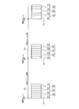
- FIG. 4 is a diagram illustrating an example of a cyclic shift of the synchronization signal by the base station according to the embodiment.
- the horizontal axis indicates the frequency.
- the subcarrier group 401 is a frequency resource assigned to the synchronization signal, and includes 63 subcarriers.
- the synchronization signals 321 to 323 (# 1 to # 3) among the synchronization signals 321 to 327 (# 1 to # 7) shown in FIG. 3 are illustrated.
- 0 to 62 of the synchronization signal 321 (# 1) are identifiers of the respective codes mapped to 63 subcarriers of the subcarrier group 401, respectively.
- this code for example, a Zadoff-Chu sequence of length 63 can be used.
- the 63 subcarriers may include subcarriers having an amplitude of zero.
- the synchronization signal 322 (# 2) transmitted next to the synchronization signal 321 (# 1) is a code string obtained by cyclically shifting the code string of the synchronization signal 321 (# 1) by two subcarriers.
- the synchronization signal 323 (# 3) transmitted next to the synchronization signal 322 (# 2) is a code string obtained by cyclically shifting the code string of the synchronization signal 322 (# 2) by two subcarriers.
- each code string is obtained by cyclically shifting the synchronization signals 321 to 327 (# 1 to # 7) by two subcarriers, but the synchronization signals 321 to 327 (# 1 to # 7) are set to one substring.
- Each code string may be cyclically shifted by carriers or 3 subcarriers or more.
- CS is a known value in base station 110 and terminal 120, for example.
- FIG. 5 is a flowchart illustrating an example of a synchronization signal transmission process by the base station according to the embodiment.
- the base station 110 according to the embodiment executes, for example, each step shown in FIG. 5 as the synchronization signal transmission process.
- FIG. 5 a case where the base station 110 transmits a synchronization signal using an OFDM symbol will be described.
- the base station 110 determines whether or not the current OFDM symbol time interval is a synchronization signal transmission target time interval (step S501), and the current OFDM symbol time interval is a synchronization signal transmission target time interval.
- Step S501 No loop.
- the time interval for transmission of the synchronization signal is the interval of the synchronization signals 321 to 327 (# 1 to # 7) in each radio frame interval, that is, the first 7 symbols of each radio frame interval. It is a section.
- step S501 when the current OFDM symbol time interval becomes a synchronization signal transmission target time interval (step S501: Yes), the base station 110 proceeds to step S502. That is, the base station 110 calculates D obtained by dividing the time difference between the radio frame boundary and the start point of the current OFDM symbol time interval by the OFDM symbol length (step S502).
- the synchronization signal to be transmitted in the current OFDM symbol time interval is the D + 1th synchronization signal from the radio frame boundary.
- the base station 110 calculates a cyclic shift amount L obtained by multiplying D calculated in step S502 by CS (cyclic shift unit amount) (step S503).
- the base station 110 cyclically shifts the code sequence of the predetermined synchronization signal by L calculated in step S503 (step S504).
- the predetermined synchronization signal is, for example, a code string of the synchronization signal 321 (# 1) shown in FIG.
- the base station 110 sets a beam angle based on D calculated in step S502 (step S505). For example, assuming that the beam angle of the beam 211 (# 0) is a degree in the example illustrated in FIG. 2, the base station 110 sets a + 20 ⁇ D degrees in step S505.
- the base station 110 performs signal processing on the code sequence cyclically shifted in step S504, and transmits the signal processed code sequence from a plurality of transmission antennas at the beam angle set in step S505 (step S506).
- the base station 110 can transmit the code string at the beam angle set in step S505 by weighting each transmission antenna and transmitting the code string in step S506.
- the base station 110 may store each code string of the synchronization signal to be transmitted and transmit each code string of the stored synchronization signal at a timing to be transmitted.
- FIG. 6 is a flowchart illustrating an example of synchronization processing by the terminal according to the embodiment.
- the terminal 120 according to the embodiment executes, for example, each step shown in FIG. 6 as synchronization processing based on the synchronization signal transmitted from the base station 110.
- the terminal 120 sets its own reception area in a frequency area where the synchronization signal may be transmitted from the base station 110 (step S601).
- the frequency region in which the synchronization signal may be transmitted is the frequency region of the subcarrier group 401.
- the terminal 120 performs a detection process of the synchronization signal from the base station 110 in the time domain using the replica of the synchronization signal (step S602). For example, the terminal 120 performs synchronization signal detection processing by comparing, in the time domain, the received signal in the reception area set in step S601 and a replica of the synchronization signal.
- the replica of the synchronization signal used in step S602 is a signal in the time domain of the same code string as the synchronization signal 321 (# 1) shown in FIG.
- the terminal 120 determines whether or not a synchronization signal has been detected by the detection process in step S602 (step S603).
- the terminal 120 returns to step S602.
- the terminal 120 performs FFT on the detected synchronization signal (step S604).
- FFT is an abbreviation for Fast Fourier Transform. As a result, the synchronization signal is converted from the time domain to the frequency domain.
- the terminal 120 compares the synchronization signal FFTed in Step S604 with the replica of the synchronization signal in the frequency domain, and detects the amount of cyclic shift applied to the detected synchronization signal (Step S605).
- the terminal 120 compares the synchronization signal FFTed in step S604 with a replica of the synchronization signal while cyclically shifting the CS by CS. Then, the terminal 120 detects the cyclic shift amount when the compared synchronization signal matches the replica as the cyclic shift amount applied to the detected synchronization signal.
- the replica of the synchronization signal used in step S605 is a code string in the same frequency domain as that of the synchronization signal 321 (# 1) shown in FIG.
- the terminal 120 holds the detection time when the synchronization signal is detected (step S606).
- the detection time when the synchronization signal is detected is the time when it is determined in step S603 that the synchronization signal is detected. If the time taken from the detection of the synchronization signal in step S603 to the transition to step S606 is sufficiently short, the detection time for detecting the synchronization signal may be the time when the transition to step S606 is performed.
- step S607 determines whether or not the cyclic shift amount detected in step S605 is 0 (step S607).
- the terminal 120 determines that the radio frame start time (radio frame boundary) is the detection time held in step S606 (step S608). Then, a series of synchronization processing is finished.
- step S607 when the detected cyclic shift amount is not 0 (step S607: No), the terminal 120 proceeds to step S609. That is, the terminal 120 calculates the amount obtained by dividing the cyclic shift amount detected in step S605 by CS and multiplying by the OFDM symbol length as the time difference from the detected radio frame boundary of the synchronization signal (step S609). ).
- the terminal 120 calculates, as a radio frame start time, a value obtained by subtracting the time difference from the radio frame boundary calculated in step S609 from the detection time held in step S606 (step S610), and performs a series of synchronization processes. finish. Note that steps S607 and S608 may be omitted, and the process may be shifted from step S606 to step S609 even if the cyclic shift amount is zero.
- the terminal 120 may change the reception area set in step S601 and return to step S602. .
- the terminal 120 may receive the synchronization signal a plurality of times, calculate each cyclic shift amount based on each received synchronization signal, and specify the radio frame start time based on each calculated cyclic shift amount. . Thereby, it is possible to specify the radio frame start time with higher accuracy. For example, the terminal 120 specifies the radio frame start time based on the cyclic shift amount having the highest calculation frequency among the calculated cyclic shift amounts. Alternatively, the terminal 120 may specify the radio frame start time based on the cyclic shift amount obtained by averaging the calculated cyclic shift amounts.
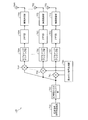
- FIG. 7 is a diagram of an example of the base station according to the embodiment.
- the base station 110 includes, for example, a synchronization signal code sequence generation unit 710, a code sequence cyclic shift unit 720, and a weighting signal generation unit 730.
- Base station 110 includes weighting sections 741 to 74M, subcarrier mapping sections 751 to 75M, IFFT sections 761 to 76M, radio transmission sections 771 to 77M, and transmission antennas 781 to 78M, for example.
- IFFT is an abbreviation for Inverse Fast Fourier Transform (Inverse Fast Fourier Transform).
- the synchronization signal code string generation unit 710 generates a code string of a predetermined synchronization signal.
- the code sequence of the synchronization signal generated by the synchronization signal code sequence generation unit 710 is a frequency-domain code sequence of the synchronization signal 321 (# 1) illustrated in FIG.
- the synchronization signal code string generation unit 710 outputs the generated synchronization signal to the code string cyclic shift unit 720.
- the code string cyclic shift unit 720 cyclically shifts the code string of the synchronization signal output from the synchronization signal code string generation unit 710. For example, the code string cyclic shift unit 720 changes the cyclic shift amount in units of CS according to the temporal distance between the transmission timing of the synchronization signal to be cyclic shifted and the radio frame boundary. Further, the code string cyclic shift unit 720 outputs a synchronization signal obtained by cyclically shifting the code string to the weighting units 741 to 74M.
- the weighting signal generation unit 730 generates weighting factors for transmission beam formation in the weighting units 741 to 74M. For example, the weighting signal generation unit 730 performs weighting so that the transmission direction of the synchronization signal differs according to the temporal distance between the transmission timing of the synchronization signal input to the weighting units 741 to 74M and the radio frame boundary. Each weight coefficient in the units 741 to 74M is generated. Then, the weighting signal generation unit 730 outputs the generated weighting coefficients to the weighting units 741 to 74M, respectively.
- Each of the weighting units 741 to 74M weights the synchronization signal output from the code string cyclic shift unit 720 by multiplying the weighting coefficient output from the weighting signal generation unit 730. Then, the weighting units 741 to 74M output the weighted synchronization signals to the subcarrier mapping units 751 to 75M, respectively.
- the subcarrier mapping units 751 to 75M map the synchronization signals output from the weighting units 741 to 74M to the subcarriers, respectively.
- the subcarriers to which the subcarrier mapping units 751 to 75M perform mapping are, for example, the subcarrier group 401 shown in FIG.
- Subcarrier mapping sections 751 to 75M output the synchronization signals mapped to the subcarriers to IFFT sections 761 to 76M, respectively.
- IFFT units 761 to 76M perform IFFT on the synchronization signals output from the subcarrier mapping units 751 to 75M, respectively.
- the synchronization signals output from the subcarrier mapping units 751 to 75M are converted from the frequency domain to the time domain.
- IFFT units 761 to 76M output the synchronization signals subjected to IFFT to radio transmission units 771 to 77M, respectively.
- the wireless transmission units 771 to 77M perform wireless transmission processing on the synchronization signals output from the IFFT units 761 to 76M, respectively.
- Each wireless transmission process in the wireless transmission units 771 to 77M includes, for example, I / Q orthogonal modulation, conversion from a digital signal to an analog signal, frequency conversion from a baseband to a high frequency band, amplification, and the like.
- Radio transmission sections 771 to 77M output the synchronization signals subjected to the radio transmission processing to transmission antennas 781 to 78M, respectively.
- the transmission antennas 781 to 78M wirelessly transmit the synchronization signals output from the wireless transmission units 771 to 77M, respectively. Accordingly, the synchronization signal output from the code string cyclic shift unit 720 is beam-formed and wirelessly transmitted.
- the beam angle of the synchronization signal wirelessly transmitted from the transmission antennas 781 to 78M is determined by the weighting coefficient generated by the weighting signal generation unit 730. Further, the weighting signal generation unit 730 changes the weighting factor for each synchronization signal. Also, the code string cyclic shift unit 720 cyclically shifts the code string for each synchronization signal. Accordingly, the synchronization signal is transmitted in a plurality of beam directions by beam sweeping. In addition, the cyclic shift amount of the code string of the synchronization signal changes according to the beam direction.
- the transmission unit 112 shown in FIG. 1 includes, for example, a weighting signal generation unit 730, weighting units 741 to 74M, subcarrier mapping units 751 to 75M, IFFT units 761 to 76M, radio transmission units 771 to 77M, and transmission antennas 781 to 78M. Can be realized.
- FIG. 8 is a diagram illustrating an example of a terminal according to the embodiment.
- the terminal 120 includes, for example, a reception antenna 810, an RF reception unit 820, a synchronization signal code string generation unit 830, an IFFT unit 840, and a detection unit 850.
- Terminal 120 includes, for example, FFT section 860, comparison section 870, and radio frame boundary specifying section 880.
- RF is an abbreviation for Radio Frequency.
- the receiving antenna 810 receives a signal wirelessly transmitted from the base station 110.
- the signal wirelessly transmitted from the base station 110 includes a synchronization signal.
- Reception antenna 810 outputs the received signal to detection unit 850.
- the RF receiving unit 820 performs wireless reception processing on the signal output from the receiving antenna 810.
- the radio reception processing by the RF receiving unit 820 includes, for example, amplification, frequency conversion from a high frequency band to a baseband, conversion from an analog signal to a digital signal, orthogonal demodulation, and the like.
- the RF reception unit 820 outputs a signal subjected to the wireless reception process to the detection unit 850.
- the synchronization signal code string generation unit 830 generates the same code string as the synchronization signal transmitted by the base station 110. For example, the synchronization signal code string generation unit 830 generates the same code string as the code string generated by the synchronization signal code string generation unit 710 illustrated in FIG. Then, synchronization signal code string generation section 830 outputs the generated synchronization signal code string to IFFT section 840 and comparison section 870.
- the IFFT unit 840 performs IFFT on the synchronization signal output from the synchronization signal code string generation unit 830. As a result, the synchronization signal output from the synchronization signal code string generation unit 830 is converted from the frequency domain to the time domain. Then, IFFT unit 840 outputs the synchronization signal subjected to IFFT to detection unit 850.
- the detection unit 850 compares the signal output from the RF reception unit 820 and the synchronization signal output from the IFFT unit 840 in the time domain, so that the base station included in the signal output from the RF reception unit 820 The synchronization signal from 110 is detected. Then, the detection unit 850 outputs the detected synchronization signal to the FFT unit 860.
- the FFT unit 860 performs FFT on the synchronization signal output from the detection unit 850. As a result, the synchronization signal output from the detection unit 850 is converted from the time domain to the frequency domain. Then, FFT section 860 outputs the synchronization signal subjected to the FFT to comparison section 870.
- the comparison unit 870 compares the code sequence of the synchronization signal output from the FFT unit 860 with the code sequence of the synchronization signal output from the synchronization signal code sequence generation unit 830 while cyclically shifting the code sequence by CS. Then, comparing section 870 notifies radio frame boundary specifying section 880 of the cyclic shift amount when the compared code strings match.
- Radio frame boundary specifying section 880 performs radio transmission in base station 110 based on the amount of cyclic shift notified from comparison section 870 and the reception timing (for example, current time) of the synchronization signal to which the amount of cyclic shift is applied. Identify frame boundaries.
- the memory of terminal 120 stores correspondence information that associates the amount of cyclic shift applied to the synchronization signal and the relationship information (for example, time difference) indicating the relationship between the timing of the synchronization signal and the radio frame boundary.
- radio frame boundary specifying section 880 acquires relation information corresponding to the cyclic shift amount notified from comparison section 870 from the correspondence information, and determines the base from the received correspondence information and the reception timing (for example, current time) of the synchronization signal.
- a radio frame boundary at station 110 is identified.
- the correspondence information may be a calculation formula as shown in steps S607 to S610 in FIG. 6, or may be a table, for example.
- the radio frame boundary specifying unit 880 notifies the higher-level processing unit of the terminal 120 of the specified radio frame boundary.
- the upper processing unit performs processing for performing wireless communication with the base station 110 based on the wireless frame boundary notified from the wireless frame boundary specifying unit 880.
- a processing unit for removing CP (Cyclic Prefix) attached to the synchronization signal may be provided between the detection unit 850 and the FFT unit 860. Good.
- the receiving unit 121 shown in FIG. 1 can be realized by, for example, the receiving antenna 810 and the RF receiving unit 820.
- the identifying unit 122 illustrated in FIG. 1 can be realized by, for example, the synchronization signal code string generating unit 830, the IFFT unit 840, the detecting unit 850, the FFT unit 860, the comparing unit 870, and the radio frame boundary identifying unit 880.
- FIG. 9 is a diagram illustrating an example of a hardware configuration of the base station according to the embodiment.
- the base station 110 shown in FIG. 7 can be realized by the communication apparatus 900 shown in FIG. 9, for example.
- the communication device 900 includes a CPU 901, a memory 902, a wireless communication interface 903, and a wired communication interface 904.
- the CPU 901, the memory 902, the wireless communication interface 903, and the wired communication interface 904 are connected by a bus 909.
- a CPU 901 Central Processing Unit controls the entire communication device 900.
- the memory 902 includes, for example, a main memory and an auxiliary memory.
- the main memory is, for example, a RAM (Random Access Memory).
- the main memory is used as a work area for the CPU 901.
- the auxiliary memory is, for example, a nonvolatile memory such as a magnetic disk, an optical disk, or a flash memory.
- Various programs for operating the communication device 900 are stored in the auxiliary memory. The program stored in the auxiliary memory is loaded into the main memory and executed by the CPU 901.
- the wireless communication interface 903 is a communication interface that performs communication with the outside of the communication device 900 (for example, the terminal 120) wirelessly.
- the wireless communication interface 903 is controlled by the CPU 901.
- the wired communication interface 904 is a communication interface that performs communication with the outside of the communication device 900 (for example, a host device of the base station 110) by wire.
- the wired communication interface 904 is controlled by the CPU 901.
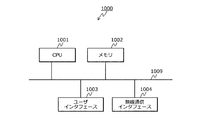
- FIG. 10 is a diagram illustrating an example of a hardware configuration of the terminal according to the embodiment.
- the terminal 120 shown in FIG. 8 can be realized by the communication apparatus 1000 shown in FIG. 10, for example.
- the communication apparatus 1000 includes a CPU 1001, a memory 1002, a user interface 1003, and a wireless communication interface 1004.
- the CPU 1001, the memory 1002, the user interface 1003, and the wireless communication interface 1004 are connected by a bus 1009.
- the CPU 1001 controls the entire communication device 1000.
- the memory 1002 includes, for example, a main memory and an auxiliary memory.
- the main memory is, for example, a RAM.
- the main memory is used as a work area for the CPU 1001.
- the auxiliary memory is a non-volatile memory such as a magnetic disk or a flash memory.
- Various programs for operating the communication device 1000 are stored in the auxiliary memory.
- the program stored in the auxiliary memory is loaded into the main memory and executed by the CPU 1001.
- the user interface 1003 includes, for example, an input device that receives an operation input from the user, an output device that outputs information to the user, and the like.
- the input device can be realized by a key (for example, a keyboard) or a remote controller, for example.
- the output device can be realized by, for example, a display or a speaker. Further, an input device and an output device may be realized by a touch panel or the like.
- the user interface 1003 is controlled by the CPU 1001.
- the wireless communication interface 1004 is a communication interface that performs communication with the outside of the communication apparatus 1000 (for example, the base station 110) wirelessly.
- the wireless communication interface 1004 is controlled by the CPU 1001.
- the synchronization signal code string generation unit 830, the IFFT unit 840, the detection unit 850, the FFT unit 860, the comparison unit 870, and the radio frame boundary specifying unit 880 illustrated in FIG. 8 are realized by at least one of the CPU 1001 and the radio communication interface 1004, for example. can do.
- the base station transmits a plurality of code sequences transmitted in different time intervals, and the predetermined code is an amount corresponding to the difference between the time interval transmitted and the reference timing.
- a plurality of code strings obtained by cyclically shifting the strings can be transmitted.
- the terminal can specify the reference timing based on the amount of cyclic shift applied to the code string transmitted from the base station and the time interval in which the code string is received from the base station.
- the terminal can specify the reference timing in the base station based on the code sequence received by the terminal itself. .
- the terminal can identify the boundary of the radio frame based on a synchronization signal transmitted from the base station by beam sweeping.
- the wireless device that performs wireless communication with the terminal is not limited to the base station, and may be, for example, a remote device connected to the base station, a relay device that relays communication between the terminal and the base station, or the like. That is, a wireless device such as a remote device or a relay device is a plurality of code sequences transmitted in different time intervals, and a predetermined code corresponding to the difference between the time interval to be transmitted and the reference timing. A plurality of code strings obtained by cyclically shifting the strings may be transmitted.
- the plurality of code sequences transmitted by the base station 110 may be discovery signals transmitted by the base station 110 in order for the terminal 120 to detect the base station 110.
- the reference timing of the base station 110 specified by the plurality of code strings can be, for example, a timing at which the terminal 120 transmits an RA (Random Access) signal to the base station 110.
- the timing at which the terminal transmits the RA signal can be specified based on the discovery signal transmitted by the base station by beam sweeping.
- the terminal can specify the reference timing even if the base station transmits a signal by beam sweeping.
- the fifth generation mobile communication system is expected to start commercial service from around 2020.
- a peak data rate of up to 20 [Gbps] should be obtained in the DL (Down Link) radio section, and up to 10 [Gbps] in the UL (Up Link) radio section.
- ITU is an abbreviation for International Telecommunication Union.
- a millimeter wave band that can secure a wide band can be used.
- radio wave propagation loss increases and the radio cell becomes small.
- it is considered effective to expand the radio cell range by performing beamforming transmission using a multi-element antenna.
- the data rate can be increased by performing spatial stream multiplex transmission using a multi-element antenna.
- the use of multi-element antennas in the millimeter wave band is considered an effective method.
- the maximum number of antenna elements included in one transmission antenna is assumed to be 256, for example.
- One of the important things in wireless cellular communication is to enable the terminal to receive signals (for example, system control signals) required to connect the terminal to the base station and maintain the connection by the terminal throughout the wireless cell. It is.
- beamforming transmission beam generation based on the arrival angle obtained from the measurement of the signal transmitted by the terminal
- beam sweeping transmission in which a narrow-width beam is transmitted a plurality of times so as to reach the entire area within the cell by changing the beam angle is applied Is being considered.
- a radio downlink synchronization signal (for example, a synchronization signal corresponding to LTE PSS or SSS), which is one of common radio signals, is transmitted by beam sweeping in the millimeter wave band. Is being considered.
- Whether to use digital beam forming, analog beam forming, or hybrid beam forming when performing signal beam forming transmission using a multi-element transmission antenna depends on the implementation. However, the radio signal introduced into the radio section of the fifth generation mobile communication system is required not to depend on these beam forming methods. That is, even if the type of beamforming method used on the base station side is unknown at the terminal, it is required that the terminal can receive a radio signal transmitted by beamforming.
- Hybrid beam forming is a combination of digital beam forming and analog beam forming.
- the number of beams transmitted at the same time can be varied by making the setting content of the phase matrix given between the antenna elements appropriate. As the number of beams increases, the power allocated to one beam decreases and the beam reach decreases, and when the power allocated to one beam is the same, the beam reach decreases as the beam width increases. .
- the beam width and the number of sweeps are considered to depend on the implementation considering the cell size, the configuration of the transmission antenna, the radio carrier frequency, and the like.
- the terminal needs to be able to receive a signal to be transmitted by beam sweeping without knowing the beam width and the number of sweeps of the base station.
- the synchronization signal is used, for example, for processing for the terminal to perform a rough level time-frequency synchronization with the base station.
- the synchronization signal is used for the terminal to estimate the cell ID of the base station and to specify the time boundary (leading portion, terminating portion) of a 10 [ms] long radio frame.
- the conventional technology cannot specify the number of beams transmitted in beam sweeping for the synchronization signal received by the terminal. For this reason, in the prior art, the terminal cannot achieve frame synchronization based on a synchronization signal transmitted from the base station by beam sweeping.
- the terminal cyclically shifts the code sequence of each synchronization signal transmitted by the base station by beam sweeping according to the time difference from the frame boundary, so that the terminal The frame boundary can be specified by the cyclic shift amount.
- the terminal identifies the RA transmission timing based on the cyclic shift amount of the received code sequence by cyclically shifting the code sequence of each discovery signal transmitted by the base station by beam sweeping according to the time difference from the frame boundary. Is possible.
- the present invention can be applied not only to the specification of the frame boundary based on the synchronization signal and the specification of the RA transmission timing based on the discovery signal.
- the cyclic shift amount of the code string of the synchronization signal may be associated with the time relationship between the synchronization signal and another signal.
- the terminal can specify the time when another signal is transmitted based on the cyclic shift amount of the received synchronization signal and the timing at which the synchronization signal is received.
- the cyclic shift amount of the code string of the synchronization signal may be associated with the frequency relationship between the synchronization signal and another signal. Accordingly, the terminal can specify the frequency at which another signal is transmitted based on the cyclic shift amount of the received synchronization signal and the frequency at which the synchronization signal is received.
- the cyclic shift amount of the code string of the synchronization signal may be associated with the relationship between the synchronization signal and a specific carrier frequency. Accordingly, the terminal can specify a specific carrier frequency based on the cyclic shift amount of the received synchronization signal and the frequency at which the synchronization signal is received.
- the cyclic shift amount of the code string of the synchronization signal is associated with the relationship between the time and frequency of the synchronization signal and another signal or the relationship with a specific carrier frequency
- the cyclic shift amount of the code string of the discovery signal may be associated with the relationship between the discovery signal and other signals in time or frequency, or the relationship with a specific carrier frequency.
Landscapes
- Engineering & Computer Science (AREA)
- Computer Networks & Wireless Communication (AREA)
- Signal Processing (AREA)
- Mobile Radio Communication Systems (AREA)
Abstract
基地局(110)は、第1時間区間と自局の無線信号の送信基準タイミングとの間の差に応じた量だけ所定の符号列を巡回シフトした第1符号列を生成して第1時間区間で送信する。また、基地局(110)は、第1時間区間と異なる第2時間区間と前記送信基準タイミングとの間の差に応じた量だけ所定の符号列を巡回シフトした第2符号列を生成して第2時間区間で送信する。端末(120)は、基地局(110)から送信された符号列に適用されている巡回シフトの量と、基地局(110)からその符号列を受信した時間区間と、に基づいて基地局(110)から送信される無線信号の送信基準タイミングを特定する。
Description
本発明は、端末、無線装置、通信システムおよび通信方法に関する。
従来、第3世代移動体通信システム(3G)、第3.9世代移動体通信システムに対応するLTE、第4世代移動体通信システムに対応するLTE-Advancedなどの移動体通信システムが知られている。LTEはLong Term Evolutionの略である。また、第5世代移動体通信システム(5G)に関する技術の検討も開始されている(たとえば、下記非特許文献1参照。)。第5世代移動体通信システムにおいては、たとえば、基地局が無線信号をビームスイーピング(beam sweeping)により送信することが検討されている。
また、第5世代移動体通信システム等の移動体通信システムにおいては、たとえば端末が基地局から送信されるダウンリンク無線信号の送信基準タイミング(たとえば無線フレームの時間領域における境界)を特定するために、基地局から同期信号が送信される。
Nokia、Alcatel-Lucent Shanghai Bell、"Support for Beam Based Common Control Plane"、3GPP、R1-165364
しかしながら、上述した従来技術においては、基地局が同期信号等の信号をビームスイーピングで送信しても、無線フレームの境界等の基地局の基準タイミングを端末が特定することが求められる。
たとえば、基地局が同期信号等の信号をビームスイーピングにより送信すると、端末は基地局から受信した信号がビームスイーピングのいずれの段階で送信された信号であるかを判別することができない。このため、端末は、基地局から受信した信号に基づいて基地局の基準タイミングを特定することができない。
1つの側面では、本発明は、基地局が信号をビームスイーピングで送信しても端末が基準タイミングを特定することができる端末、無線装置、通信システムおよび通信方法を提供することを目的とする。
上述した課題を解決し、目的を達成するため、本発明の一側面によれば、無線装置が、第1時間区間と自装置の無線信号の送信基準タイミングとの間の差に応じた量だけ所定の符号列を巡回シフトした第1符号列を前記第1時間区間で送信し、前記第1時間区間と異なる第2時間区間と前記送信基準タイミングとの間の差に応じた量だけ前記所定の符号列を巡回シフトした第2符号列を前記第2時間区間で送信し、端末が、前記無線装置から送信された符号列に適用されている巡回シフトの量と、前記無線装置から前記符号列を受信した時間区間と、に基づいて前記送信基準タイミングを特定する端末、無線装置、通信システムおよび通信方法が提案される。
本発明の一側面によれば、基地局が信号をビームスイーピングで送信しても端末が基準タイミングを特定することができるという効果を奏する。
以下に図面を参照して、本発明にかかる端末、無線装置、通信システムおよび通信方法の実施の形態を詳細に説明する。
(実施の形態)
(実施の形態にかかる通信システム)
図1は、実施の形態にかかる通信システムの一例を示す図である。図1に示すように、実施の形態にかかる通信システム100は、基地局110と、端末120と、を含む。基地局110は、自セルに在圏する端末との間で無線通信が可能な無線基地局である。端末120は、基地局110のセルに在圏する無線端末である。
(実施の形態にかかる通信システム)
図1は、実施の形態にかかる通信システムの一例を示す図である。図1に示すように、実施の形態にかかる通信システム100は、基地局110と、端末120と、を含む。基地局110は、自セルに在圏する端末との間で無線通信が可能な無線基地局である。端末120は、基地局110のセルに在圏する無線端末である。
基地局110は、生成部111および送信部112を備える。生成部111は、それぞれ異なる時間区間で送信する複数の符号列を生成する。生成部111は、生成した複数の符号列のそれぞれを、その符号列を送信するタイミングで送信部112へ出力する。
生成部111が生成する符号列は、たとえば後述の同期信号またはディスカバリ信号である。同期信号は、たとえばLTEにおけるPSS(Primary Synchronization Signal:プライマリ同期信号)やSSS(Secondary Synchronization Signal:セカンダリ同期信号)である。ただし、同期信号はこれらに限らず各種の同期信号とすることができる。
また、生成部111は、生成する複数の符号列を、それぞれ送信する時間区間および基準タイミングの間の差に応じた量だけ所定の符号列をサイクリックシフト(巡回シフト)した複数の符号列とする。すなわち、生成部111が生成する複数の符号列は、サイクリックシフトすると互いに一致する関係を互いに有する。
所定の符号列は、たとえば基地局110および端末120において既知の符号列である。基準タイミングは、たとえば基地局110が行う無線通信の基準となるタイミングである。たとえば、複数の符号列が同期信号である場合は、基準タイミングはたとえば無線フレームまたは無線スロットの境界(開始点)である。また、基準タイミングは、無線フレームまたは無線スロットの境界に限らず、無線フレーム内または無線スロット内の特定のタイミングであってもよい。たとえば、基準タイミングは、無線フレーム内の特定の無線サブフレームの開始点または無線フレーム内の特定の無線サブフレーム内の特定の無線スロットの開始点であってもよい。無線フレーム内の特定の無線サブフレームは、たとえばシステム情報が含まれる無線信号の送信に使用される無線サブフレームである。
たとえば、生成部111が生成する複数の符号列には第1符号列および第2符号列が含まれる。第1符号列は、第1時間区間で送信され、第1時間区間と基準タイミングとの間の差に応じた量だけ所定の符号列をサイクリックシフトした符号列である。第2符号列は、第1時間区間と異なる第2時間区間で送信され、第2時間区間と基準タイミングとの間の差に応じた量だけ所定の符号列をサイクリックシフトした符号列である。
また、符号列を送信する時間区間および基準タイミングの間の差に応じたサイクリックシフトの量には0が含まれていてもよい。すなわち、基地局110が生成する複数の符号列には所定の符号列自体が含まれていてもよい。
たとえば、生成部111は、所定の符号列をサイクリックシフトすることによって複数の符号列を生成する。ただし、このような構成に限らず、たとえばサイクリックシフトすると互いに一致する各符号列を基地局110のメモリに記憶しておき、生成部111はその各符号列を読み出すことによって複数の符号列を生成してもよい。
送信部112は、生成部111から出力された符号列を自セル内に無線送信する。また、送信部112は、生成部111から出力された符号列を、送信するタイミングによって異なる方向のビームにより送信するビームスイーピングを行ってもよい。たとえば、送信部112は、第1符号列および第2符号列を送信する場合に、送信に用いる複数の送信アンテナの間の位相差を、第1符号列を送信する時と第2符号列を送信する時で独立に設定することによってビームスイーピングを行う。
端末120は、受信部121および特定部122を備える。受信部121は、基地局110から無線送信された符号列を受信する。そして、受信部121は、受信した符号列を特定部122へ出力する。
特定部122は、受信部121から出力された符号列に適用されているサイクリックシフトの量を判定する。たとえば、特定部122は、受信部121から出力された符号列を所定量ずつサイクリックシフトさせながら所定の符号列と比較し、比較した各符号列が一致した時のサイクリックシフトの量を判定する。また、特定部122は、判定したサイクリックシフトの量と、受信部121から出力された符号列を受信部121が受信した時間区間と、に基づいて、基地局110における基準タイミングを特定する。
たとえば、特定部122は、基地局110から符号列を受信する時間区間および基準タイミングの間の差と、サイクリックシフトの量と、の間の対応関係を示す対応情報を用いて基準タイミングを特定する。これにより、基地局110が符号列(たとえば同期信号)をビームスイーピングにより送信していても、端末120は、基地局110における基準タイミングを特定し、基地局110との間で無線通信を行うことが可能になる。
(実施の形態にかかる基地局による同期信号のビームスイーピング)
図2は、実施の形態にかかる基地局による同期信号のビームスイーピングの一例を示す図である。図2に示す送信点201は、同期信号を送信する基地局110に接続される送信アンテナまたは送受信アンテナの位置である。送信点201は、基地局110と同じ場所にある場合や、基地局110から離れている場合がある。離れている場合、送信点201は、たとえば、遠隔装置(Remote Unitや Distributed Unit等)等になる。ビーム211~217(#1~#7)は、基地局110が送信点201からスイーピングさせながら送信する各ビームである。図2に示す例では、基地局110は、約120度幅のひとつの無線セル内において、同期信号を約20度ずつずらしながら7回送信する。7回の送信のそれぞれの送信においては、7個のビーム211~217(#1~#7)の中の一つをたとえば順に用いる。
図2は、実施の形態にかかる基地局による同期信号のビームスイーピングの一例を示す図である。図2に示す送信点201は、同期信号を送信する基地局110に接続される送信アンテナまたは送受信アンテナの位置である。送信点201は、基地局110と同じ場所にある場合や、基地局110から離れている場合がある。離れている場合、送信点201は、たとえば、遠隔装置(Remote Unitや Distributed Unit等)等になる。ビーム211~217(#1~#7)は、基地局110が送信点201からスイーピングさせながら送信する各ビームである。図2に示す例では、基地局110は、約120度幅のひとつの無線セル内において、同期信号を約20度ずつずらしながら7回送信する。7回の送信のそれぞれの送信においては、7個のビーム211~217(#1~#7)の中の一つをたとえば順に用いる。
これはスイープ数=7のビームスイーピングとなる。この場合は、一連のビームスイーピングを行うために、同期信号を送信可能な無線リソースを時間領域方向に7個配置することを要する。同期信号を送信可能な無線リソースは、たとえば同期信号をOFDM(Orthogonal Frequency Division Multiplexing:直交周波数分割多重)により送信する場合はOFDMシンボルである。
(実施の形態にかかる基地局がビームスイーピングにより送信する同期信号)
図3は、実施の形態にかかる基地局がビームスイーピングにより送信する同期信号の一例を示す図である。図3において、横軸は時間を示す。無線フレーム区間301,302,…のそれぞれは、ひとつの無線フレームの区間(たとえば10[ms]のサブフレーム)である。無線フレーム境界311~313,…は、無線フレーム区間301,302,…の各境界である。
図3は、実施の形態にかかる基地局がビームスイーピングにより送信する同期信号の一例を示す図である。図3において、横軸は時間を示す。無線フレーム区間301,302,…のそれぞれは、ひとつの無線フレームの区間(たとえば10[ms]のサブフレーム)である。無線フレーム境界311~313,…は、無線フレーム区間301,302,…の各境界である。
同期信号321~327は、無線フレーム区間301,302,…のそれぞれにおいて基地局110がビームスイーピングにより送信する同期信号である。同期信号321は、図2に示したビーム211(#1)により送信される同期信号である。同様に、同期信号322~327は、それぞれ図2に示したビーム212~217(#2~#7)により送信される同期信号である。
すなわち、同期信号321~327は、それぞれ異なる時間区間で送信される複数の符号列であって、それぞれ送信する時間区間および基準タイミングの間の差に応じた量だけ所定の符号列をサイクリックシフトした複数の符号列である。この場合に、所定の符号列は、たとえば同期信号321の符号列とすることができる。ただし、所定の符号列は、同期信号321の符号列に限らず、同期信号322~327や、同期信号321~327と異なりサイクリックシフトすると同期信号321~327と一致する符号列でもよい。
図3に示す例では、無線フレーム区間301,302,…のそれぞれにおいて、同期信号321が無線フレーム境界311~313,…に隣接するように、同期信号321~327が時間的に隙間なく配置されている。ただし、同期信号321~327は間隔を空けて配置されていてもよい。また、無線フレーム境界311~313,…に隣接する同期信号が同期信号321~327に含まれていなくてもよい。更には、同期信号321~327の間は間隔を空けず、同期信号321と無線フレームの境界に間隔を空けてもよい。
(実施の形態にかかる基地局による同期信号のサイクリックシフト)
図4は、実施の形態にかかる基地局による同期信号のサイクリックシフトの一例を示す図である。図4においては、横軸が周波数を示している。サブキャリア群401は、同期信号に割り当てられた周波数リソースであり、63個のサブキャリアを含む。図4においては、たとえば図3に示した同期信号321~327(#1~#7)のうちの同期信号321~323(#1~#3)を図示している。
図4は、実施の形態にかかる基地局による同期信号のサイクリックシフトの一例を示す図である。図4においては、横軸が周波数を示している。サブキャリア群401は、同期信号に割り当てられた周波数リソースであり、63個のサブキャリアを含む。図4においては、たとえば図3に示した同期信号321~327(#1~#7)のうちの同期信号321~323(#1~#3)を図示している。
同期信号321(#1)の0~62は、それぞれサブキャリア群401の63個のサブキャリアにマッピングされた各符号の識別子である。この符号には、たとえば長さ63のZadoff-Chuシーケンスを用いることができる。この63個のサブキャリアには振幅が零となるサブキャリアが含まれてもよい。
同期信号321(#1)の次に送信される同期信号322(#2)は、同期信号321(#1)の符号列を2サブキャリアだけサイクリックシフトさせた符号列になっている。同期信号322(#2)の次に送信される同期信号323(#3)は、同期信号322(#2)の符号列を2サブキャリアだけサイクリックシフトさせた符号列になっている。
同期信号321~323(#1~#3)の各符号列について説明したが、同期信号324~327(#4~#7)についても同様に、直前に送信される同期信号の符号列を2サブキャリアだけサイクリックシフトさせた符号列になっている。図4に示す例では同期信号321~327(#1~#7)を2サブキャリアずつサイクリックシフトさせた各符号列としたが、同期信号321~327(#1~#7)を1サブキャリアまたは3サブキャリア以上ずつサイクリックシフトさせた各符号列としてもよい。
同期信号間でサイクリックシフトさせる単位をCS(図4に示す例ではCS=2)とする。CSは、たとえば基地局110および端末120において既知の値とする。
(実施の形態にかかる基地局による同期信号の送信処理)
図5は、実施の形態にかかる基地局による同期信号の送信処理の一例を示すフローチャートである。実施の形態にかかる基地局110は、同期信号の送信処理として、たとえば図5に示す各ステップを実行する。図5に示す例では、基地局110がOFDMシンボルによって同期信号を送信する場合について説明する。
図5は、実施の形態にかかる基地局による同期信号の送信処理の一例を示すフローチャートである。実施の形態にかかる基地局110は、同期信号の送信処理として、たとえば図5に示す各ステップを実行する。図5に示す例では、基地局110がOFDMシンボルによって同期信号を送信する場合について説明する。
まず、基地局110は、現在のOFDMシンボル時間区間は同期信号の送信対象の時間区間であるか否かを判断し(ステップS501)、現在のOFDMシンボル時間区間が同期信号の送信対象の時間区間になるまで待つ(ステップS501:Noのループ)。同期信号の送信対象の時間区間は、たとえば図3に示した例では、各無線フレーム区間における同期信号321~327(#1~#7)の区間、すなわち各無線フレーム区間の先頭の7シンボル分の区間である。
ステップS501において、現在のOFDMシンボル時間区間が同期信号の送信対象の時間区間になると(ステップS501:Yes)、基地局110は、ステップS502へ移行する。すなわち、基地局110は、無線フレーム境界と現在のOFDMシンボル時間区間の開始点との間の時間差をOFDMシンボル長で除算して得られるDを算出する(ステップS502)。現在のOFDMシンボル時間区間において送信すべき同期信号は、無線フレーム境界からD+1番目の同期信号である。一例としては、基地局110は、現在のOFDMシンボル時間区間が、図3に示した同期信号323のOFDMシンボル時間区間である場合は、D=2を算出する。
つぎに、基地局110は、ステップS502によって算出したDにCS(サイクリックシフトの単位量)を乗じて得られるサイクリックシフト量Lを算出する(ステップS503)。つぎに、基地局110は、所定の同期信号の符号列を、ステップS503によって算出したLだけサイクリックシフトさせる(ステップS504)。所定の同期信号は、たとえば図4に示した同期信号321(#1)の符号列である。
つぎに、基地局110は、ステップS502によって算出したDに基づくビーム角度を設定する(ステップS505)。たとえば、図2に示した例においてビーム211(#0)のビーム角度をa度とすると、基地局110は、ステップS505においてa+20×D度を設定する。
つぎに、基地局110は、ステップS504によってサイクリックシフトさせた符号列を信号処理し、信号処理した符号列をステップS505によって設定したビーム角度によって複数の送信アンテナから送信し(ステップS506)、ステップS501へ戻る。たとえば、基地局110は、ステップS506において、送信アンテナごとに重み付けを行って符号列を送信することにより、符号列をステップS505によって設定したビーム角度によって送信することができる。
図5に示す例では、基地局110が同期信号を送信するごとにサイクリックシフトにより同期信号の符号列を生成する処理について説明したが、このような処理に限らない。たとえば、基地局110は、送信すべき同期信号の各符号列を記憶しておき、記憶しておいた同期信号の各符号列をそれぞれ送信すべきタイミングで送信してもよい。
(実施の形態にかかる端末による同期処理)
図6は、実施の形態にかかる端末による同期処理の一例を示すフローチャートである。実施の形態にかかる端末120は、基地局110から送信された同期信号に基づく同期処理として、たとえば図6に示す各ステップを実行する。まず、端末120は、基地局110から同期信号が送信される可能性がある周波数領域に自端末の受信領域を設定する(ステップS601)。同期信号が送信される可能性がある周波数領域は、たとえば図4に示した例ではサブキャリア群401の周波数領域である。
図6は、実施の形態にかかる端末による同期処理の一例を示すフローチャートである。実施の形態にかかる端末120は、基地局110から送信された同期信号に基づく同期処理として、たとえば図6に示す各ステップを実行する。まず、端末120は、基地局110から同期信号が送信される可能性がある周波数領域に自端末の受信領域を設定する(ステップS601)。同期信号が送信される可能性がある周波数領域は、たとえば図4に示した例ではサブキャリア群401の周波数領域である。
つぎに、端末120は、同期信号のレプリカを用いて、時間領域で基地局110からの同期信号の検出処理を行う(ステップS602)。たとえば、端末120は、ステップS601によって設定した受信領域における受信信号と同期信号のレプリカとを時間領域で比較することによって同期信号の検出処理を行う。ステップS602において用いる同期信号のレプリカは、一例としては図3に示した同期信号321(#1)と同じ符号列を時間領域にした信号である。
つぎに、端末120は、ステップS602の検出処理により同期信号を検出したか否かを判断する(ステップS603)。同期信号を検出していない場合(ステップS603:No)は、端末120は、ステップS602へ戻る。同期信号を検出した場合(ステップS603:Yes)は、端末120は、検出した同期信号に対してFFTを行う(ステップS604)。FFTはFast Fourier Transform(高速フーリエ変換)の略である。これにより、同期信号が時間領域から周波数領域に変換される。
つぎに、端末120は、ステップS604によってFFTした同期信号と同期信号のレプリカとを周波数領域で比較して、検出した同期信号に適用されたサイクリックシフト量を検出する(ステップS605)。たとえば、端末120は、ステップS604によってFFTした同期信号をCSずつサイクリックシフトさせながら同期信号のレプリカと比較する。そして、端末120は、比較した同期信号とレプリカが一致したときのサイクリックシフト量を、検出した同期信号に適用されたサイクリックシフト量として検出する。ステップS605において用いる同期信号のレプリカは、一例としては図3に示した同期信号321(#1)と同じ周波数領域の符号列である。
また、端末120は、同期信号を検出した検出時間を保持する(ステップS606)。同期信号を検出した検出時間は、ステップS603において同期信号を検出したと判断した時刻である。また、ステップS603において同期信号を検出してからステップS606へ移行するまでにかかる時間が十分に短い場合は、同期信号を検出した検出時間はステップS606へ移行した時刻であってもよい。
つぎに、端末120は、ステップS605によって検出したサイクリックシフト量が0であるか否かを判断する(ステップS607)。検出したサイクリックシフト量が0である場合(ステップS607:Yes)は、端末120は、無線フレーム開始時間(無線フレームの境界)はステップS606によって保持した検出時間であると判定し(ステップS608)、一連の同期処理を終了する。
ステップS607において、検出したサイクリックシフト量が0でない場合(ステップS607:No)は、端末120は、ステップS609へ移行する。すなわち、端末120は、検出した同期信号の無線フレーム境界との時間差として、ステップS605によって検出したサイクリックシフト量に対して、CSで除算し、OFDMシンボル長を乗じた量を算出する(ステップS609)。
つぎに、端末120は、無線フレーム開始時間として、ステップS606によって保持した検出時間から、ステップS609によって算出した無線フレーム境界からの時間差を減算した値を算出し(ステップS610)、一連の同期処理を終了する。なお、ステップS607,S608を省き、サイクリックシフト量が0であってもステップS606からステップS609へ移行する処理としてもよい。
また、端末120は、ステップS602およびステップS603において所定回数(または所定期間)以上同期信号が検出されなかった場合は、ステップS601によって設定した受信領域を変更してステップS602へ戻るようにしてもよい。
また、端末120は、同期信号を複数回受信し、受信した各同期信号に基づく各サイクリックシフト量を算出し、算出した各サイクリックシフト量に基づいて無線フレーム開始時間を特定してもよい。これにより、無線フレーム開始時間をより精度よく特定することが可能になる。たとえば、端末120は、算出した各サイクリックシフト量のうちの最も算出度数が多いサイクリックシフト量に基づいて無線フレーム開始時間を特定する。または、端末120は、算出した各サイクリックシフト量を平均したサイクリックシフト量に基づいて無線フレーム開始時間を特定してもよい。
(実施の形態にかかる基地局)
図7は、実施の形態にかかる基地局の一例を示す図である。図7に示すように、実施の形態にかかる基地局110は、たとえば、同期信号符号列生成部710と、符号列サイクリックシフト部720と、重み付け信号生成部730と、を備える。また、基地局110は、たとえば、重み付け部741~74Mと、サブキャリアマッピング部751~75Mと、IFFT部761~76Mと、無線送信部771~77Mと、送信アンテナ781~78Mと、を備える。IFFTはInverse Fast Fourier Transform(逆高速フーリエ変換)の略である。
図7は、実施の形態にかかる基地局の一例を示す図である。図7に示すように、実施の形態にかかる基地局110は、たとえば、同期信号符号列生成部710と、符号列サイクリックシフト部720と、重み付け信号生成部730と、を備える。また、基地局110は、たとえば、重み付け部741~74Mと、サブキャリアマッピング部751~75Mと、IFFT部761~76Mと、無線送信部771~77Mと、送信アンテナ781~78Mと、を備える。IFFTはInverse Fast Fourier Transform(逆高速フーリエ変換)の略である。
同期信号符号列生成部710は、所定の同期信号の符号列を生成する。同期信号符号列生成部710が生成する同期信号の符号列は、一例としては図3に示した同期信号321(#1)の周波数領域の符号列である。同期信号符号列生成部710は、生成した同期信号を符号列サイクリックシフト部720へ出力する。
符号列サイクリックシフト部720は、同期信号符号列生成部710から出力された同期信号の符号列をサイクリックシフトする。たとえば、符号列サイクリックシフト部720は、サイクリックシフトする同期信号の送信タイミングと無線フレーム境界との間の時間的な距離に応じて、サイクリックシフトする量をCS単位で変化させる。また、符号列サイクリックシフト部720は、符号列をサイクリックシフトさせた同期信号を重み付け部741~74Mへ出力する。
重み付け信号生成部730は、重み付け部741~74Mにおける送信ビーム形成用の各重み係数を生成する。たとえば、重み付け信号生成部730は、重み付け部741~74Mへ入力される同期信号の送信タイミングと無線フレーム境界との間の時間的な距離に応じてその同期信号の送信方向が異なるように、重み付け部741~74Mにおける各重み係数を生成する。そして、重み付け信号生成部730は、生成した重み係数をそれぞれ重み付け部741~74Mへ出力する。
重み付け部741~74Mのそれぞれは、符号列サイクリックシフト部720から出力された同期信号に対して、重み付け信号生成部730から出力された重み係数を乗算することによって重み付けする。そして、重み付け部741~74Mは、重み付けした同期信号をそれぞれサブキャリアマッピング部751~75Mへ出力する。
サブキャリアマッピング部751~75Mは、それぞれ重み付け部741~74Mから出力された同期信号をそれぞれサブキャリアにマッピングする。サブキャリアマッピング部751~75Mがマッピングを行うサブキャリアは、たとえば図4に示したサブキャリア群401である。サブキャリアマッピング部751~75Mは、サブキャリアにマッピングした同期信号をそれぞれIFFT部761~76Mへ出力する。
IFFT部761~76Mは、それぞれサブキャリアマッピング部751~75Mから出力された同期信号に対してIFFTを行う。これにより、サブキャリアマッピング部751~75Mから出力された同期信号が周波数領域から時間領域に変換される。そして、IFFT部761~76Mは、IFFTを行った同期信号をそれぞれ無線送信部771~77Mへ出力する。
無線送信部771~77Mは、それぞれIFFT部761~76Mから出力された同期信号に対して無線送信処理を行う。無線送信部771~77Mにおける各無線送信処理には、たとえば、I/Q直交変調、デジタル信号からアナログ信号への変換、ベースバンド帯から高周波帯への周波数変換、増幅等が含まれる。そして、無線送信部771~77Mは、無線送信処理を行った同期信号をそれぞれ送信アンテナ781~78Mへ出力する。
送信アンテナ781~78Mは、それぞれ無線送信部771~77Mから出力された同期信号を無線送信する。これにより、符号列サイクリックシフト部720から出力された同期信号がビームフォーミングされて無線送信される。
また、送信アンテナ781~78Mから無線送信される同期信号のビーム角度は重み付け信号生成部730によって生成される重み係数によって決まる。また、重み付け信号生成部730は同期信号ごとに重み係数を変化させる。また、符号列サイクリックシフト部720は同期信号ごとに符号列をサイクリックシフトさせる。これにより、ビームスイーピングによって同期信号が複数のビーム方向で送信される。また、同期信号の符号列のサイクリックシフト量がビーム方向に応じて変化する。
図1に示した生成部111は、たとえば同期信号符号列生成部710および符号列サイクリックシフト部720により実現することができる。図1に示した送信部112は、たとえば重み付け信号生成部730、重み付け部741~74M、サブキャリアマッピング部751~75M、IFFT部761~76M、無線送信部771~77Mおよび送信アンテナ781~78Mにより実現することができる。
(実施の形態にかかる端末)
図8は、実施の形態にかかる端末の一例を示す図である。図8に示すように、実施の形態にかかる端末120は、たとえば、受信アンテナ810と、RF受信部820と、同期信号符号列生成部830と、IFFT部840と、検出部850と、を備える。また、端末120は、たとえば、FFT部860と、比較部870と、無線フレーム境界特定部880と、を備える。RFはRadio Frequency(高周波)の略である。
図8は、実施の形態にかかる端末の一例を示す図である。図8に示すように、実施の形態にかかる端末120は、たとえば、受信アンテナ810と、RF受信部820と、同期信号符号列生成部830と、IFFT部840と、検出部850と、を備える。また、端末120は、たとえば、FFT部860と、比較部870と、無線フレーム境界特定部880と、を備える。RFはRadio Frequency(高周波)の略である。
受信アンテナ810は、基地局110から無線送信された信号を受信する。基地局110から無線送信された信号には同期信号が含まれる。受信アンテナ810は、受信した信号を検出部850へ出力する。
RF受信部820は、受信アンテナ810から出力された信号に対する無線受信処理を行う。RF受信部820による無線受信処理には、たとえば、増幅、高周波帯からベースバンド帯への周波数変換、アナログ信号からデジタル信号への変換、直交復調などが含まれる。RF受信部820は、無線受信処理を行った信号を検出部850へ出力する。
同期信号符号列生成部830は、基地局110が送信する同期信号と同じ符号列を生成する。たとえば、同期信号符号列生成部830は、図7に示した同期信号符号列生成部710が生成する符号列と同じ符号列を生成する。そして、同期信号符号列生成部830は、生成した同期信号の符号列をIFFT部840および比較部870へ出力する。
IFFT部840は、同期信号符号列生成部830から出力された同期信号に対してIFFTを行う。これにより、同期信号符号列生成部830から出力された同期信号が周波数領域から時間領域に変換される。そして、IFFT部840は、IFFTを行った同期信号を検出部850へ出力する。
検出部850は、RF受信部820から出力された信号と、IFFT部840から出力された同期信号と、を時間領域で比較することにより、RF受信部820から出力された信号に含まれる基地局110からの同期信号を検出する。そして、検出部850は、検出した同期信号をFFT部860へ出力する。
FFT部860は、検出部850から出力された同期信号に対してFFTを行う。これにより、検出部850から出力された同期信号が時間領域から周波数領域に変換される。そして、FFT部860は、FFTを行った同期信号を比較部870へ出力する。
比較部870は、FFT部860から出力された同期信号の符号列をCSずつサイクリックシフトさせながら、同期信号符号列生成部830から出力された同期信号の符号列と比較する。そして、比較部870は、比較した各符号列が一致したときのサイクリックシフト量を無線フレーム境界特定部880へ通知する。
無線フレーム境界特定部880は、比較部870から通知されたサイクリックシフト量と、そのサイクリックシフト量が適用された同期信号の受信タイミング(たとえば現在時刻)と、に基づいて基地局110における無線フレーム境界を特定する。
たとえば、端末120のメモリには、同期信号に適用されるサイクリックシフト量と、その同期信号のタイミングと無線フレーム境界との関係を示す関係情報(たとえば時間差分)と、を対応付ける対応情報が記憶されている。そして、無線フレーム境界特定部880は、比較部870から通知されたサイクリックシフト量に対応する関係情報を対応情報から取得し、取得した対応情報と同期信号の受信タイミング(たとえば現在時刻)から基地局110における無線フレーム境界を特定する。対応情報は、たとえば図6のステップS607~S610に示したような計算式であってもよいし、テーブルであってもよい。
無線フレーム境界特定部880は、特定した無線フレーム境界を、端末120の上位の処理部へ通知する。上位の処理部は、無線フレーム境界特定部880から通知された無線フレーム境界に基づいて、基地局110との間で無線通信を行う処理を行う。
また、同期信号にOFDM信号が用いられる場合は、たとえば検出部850とFFT部860との間に、同期信号に付されたCP(Cyclic Prefix:巡回プレフィクス)を除去する処理部を設けてもよい。
図1に示した受信部121は、たとえば受信アンテナ810およびRF受信部820により実現することができる。図1に示した特定部122は、たとえば同期信号符号列生成部830、IFFT部840、検出部850、FFT部860、比較部870および無線フレーム境界特定部880により実現することができる。
(実施の形態にかかる基地局のハードウェア構成)
図9は、実施の形態にかかる基地局のハードウェア構成の一例を示す図である。図7に示した基地局110は、たとえば図9に示す通信装置900によって実現することができる。通信装置900は、CPU901と、メモリ902と、無線通信インタフェース903と、有線通信インタフェース904と、を備える。CPU901、メモリ902、無線通信インタフェース903および有線通信インタフェース904は、バス909によって接続される。
図9は、実施の形態にかかる基地局のハードウェア構成の一例を示す図である。図7に示した基地局110は、たとえば図9に示す通信装置900によって実現することができる。通信装置900は、CPU901と、メモリ902と、無線通信インタフェース903と、有線通信インタフェース904と、を備える。CPU901、メモリ902、無線通信インタフェース903および有線通信インタフェース904は、バス909によって接続される。
CPU901(Central Processing Unit)は、通信装置900の全体の制御を司る。メモリ902には、たとえばメインメモリおよび補助メモリが含まれる。メインメモリは、たとえばRAM(Random Access Memory)である。メインメモリは、CPU901のワークエリアとして使用される。補助メモリは、たとえば磁気ディスク、光ディスク、フラッシュメモリなどの不揮発メモリである。補助メモリには、通信装置900を動作させる各種のプログラムが記憶されている。補助メモリに記憶されたプログラムは、メインメモリにロードされてCPU901によって実行される。
無線通信インタフェース903は、無線によって通信装置900の外部(たとえば端末120)との間で通信を行う通信インタフェースである。無線通信インタフェース903は、CPU901によって制御される。
有線通信インタフェース904は、有線によって通信装置900の外部(たとえば基地局110の上位装置)との間で通信を行う通信インタフェースである。有線通信インタフェース904は、CPU901によって制御される。
図7に示した同期信号符号列生成部710、符号列サイクリックシフト部720および重み付け信号生成部730は、たとえばCPU901および無線通信インタフェース903の少なくとも一方によって実現することができる。図7に示した重み付け部741~74M、サブキャリアマッピング部751~75M、IFFT部761~76M、無線送信部771~77Mおよび送信アンテナ781~78Mは、たとえば無線通信インタフェース903に含まれる。
(実施の形態にかかる端末のハードウェア構成)
図10は、実施の形態にかかる端末のハードウェア構成の一例を示す図である。図8に示した端末120は、たとえば図10に示す通信装置1000によって実現することができる。通信装置1000は、CPU1001と、メモリ1002と、ユーザインタフェース1003と、無線通信インタフェース1004と、を備える。CPU1001、メモリ1002、ユーザインタフェース1003および無線通信インタフェース1004は、バス1009によって接続される。
図10は、実施の形態にかかる端末のハードウェア構成の一例を示す図である。図8に示した端末120は、たとえば図10に示す通信装置1000によって実現することができる。通信装置1000は、CPU1001と、メモリ1002と、ユーザインタフェース1003と、無線通信インタフェース1004と、を備える。CPU1001、メモリ1002、ユーザインタフェース1003および無線通信インタフェース1004は、バス1009によって接続される。
CPU1001は、通信装置1000の全体の制御を司る。メモリ1002には、たとえばメインメモリおよび補助メモリが含まれる。メインメモリは、たとえばRAMである。メインメモリは、CPU1001のワークエリアとして使用される。補助メモリは、たとえば磁気ディスク、フラッシュメモリなどの不揮発メモリである。補助メモリには、通信装置1000を動作させる各種のプログラムが記憶されている。補助メモリに記憶されたプログラムは、メインメモリにロードされてCPU1001によって実行される。
ユーザインタフェース1003は、たとえば、ユーザからの操作入力を受け付ける入力デバイスや、ユーザへ情報を出力する出力デバイスなどを含む。入力デバイスは、たとえばキー(たとえばキーボード)やリモコンなどによって実現することができる。出力デバイスは、たとえばディスプレイやスピーカなどによって実現することができる。また、タッチパネルなどによって入力デバイスおよび出力デバイスを実現してもよい。ユーザインタフェース1003は、CPU1001によって制御される。
無線通信インタフェース1004は、無線によって通信装置1000の外部(たとえば基地局110)との間で通信を行う通信インタフェースである。無線通信インタフェース1004は、CPU1001によって制御される。
図8に示した受信アンテナ810およびRF受信部820は、たとえば無線通信インタフェース1004に含まれる。図8に示した同期信号符号列生成部830、IFFT部840、検出部850、FFT部860、比較部870および無線フレーム境界特定部880は、たとえばCPU1001と無線通信インタフェース1004の少なくともいずれかにより実現することができる。
このように、実施の形態によれば、基地局が、それぞれ異なる時間区間で送信する複数の符号列であって、それぞれ送信する時間区間および基準タイミングの間の差に応じた量だけ所定の符号列を巡回シフトした複数の符号列を送信することができる。また、端末が、基地局から送信された符号列に適用されている巡回シフトの量と、基地局から符号列を受信した時間区間と、に基づいて基準タイミングを特定することができる。
これにより、基地局が複数の符号列をそれぞれ異なる角度で送信するビームスイーピングを行う場合においても、端末は自端末が受信した符号列に基づいて基地局における基準タイミングを特定することが可能になる。たとえば、基地局がビームスイーピングで送信する同期信号に基づいて端末が無線フレームの境界を特定することができる。
なお、端末と無線通信を行う無線装置は、基地局に限らず、たとえば基地局と接続された遠隔装置や、端末と基地局との間の通信を中継する中継装置などであってもよい。すなわち、これらの遠隔装置や中継装置などの無線装置が、それぞれ異なる時間区間で送信する複数の符号列であって、それぞれ送信する時間区間および基準タイミングの間の差に応じた量だけ所定の符号列を巡回シフトした複数の符号列を送信してもよい。
(実施の形態にかかる基地局が送信する複数の符号列および基準タイミングの他の例)
基地局110が送信する複数の符号列が同期信号であり、複数の符号列によって特定される基地局110の基準タイミングが無線フレームの境界である場合について説明したが、このような構成に限らない。
基地局110が送信する複数の符号列が同期信号であり、複数の符号列によって特定される基地局110の基準タイミングが無線フレームの境界である場合について説明したが、このような構成に限らない。
たとえば、基地局110が送信する複数の符号列は、端末120が基地局110を検出するために基地局110が送信するディスカバリ信号であってもよい。この場合に、複数の符号列によって特定される基地局110の基準タイミングは、たとえば、端末120が基地局110へRA(Random Access)信号を送信するタイミングとすることができる。これにより、基地局がビームスイーピングで送信するディスカバリ信号に基づいて、端末がRA信号を送信するタイミングを特定することができる。
以上説明したように、端末、無線装置、通信システムおよび通信方法によれば、基地局が信号をビームスイーピングで送信しても端末が基準タイミングを特定することができる。
たとえば、第5世代移動体通信システムは、2020年頃から商用サービスが開始されることが期待されている。第5世代移動体通信システムにおいては、DL(Down Link)の無線区間では最大で20[Gbps]、UL(Up Link)の無線区間では最大で10[Gbps]のピークデータレートが得られるべきというITUからの要求がある。ITUはInternational Telecommunication Unionの略である。
これを実現する方法として、たとえば広帯域を確保できるミリ波帯の活用が挙げられる。ミリ波帯は電波伝搬損失が大きくなり無線セルが小さくなるが、多素子アンテナを用いてビームフォーミング送信を行うことにより無線セル範囲の拡大を行うことが有効と考えられている。さらに、多素子アンテナを用いて空間ストリーム多重送信を行うことで、データレートの増加を図ることができる。
したがって、ミリ波帯における多素子アンテナの活用は有効な方法と考えられている。一つの送信アンテナに含まれるアンテナ素子数は最大でたとえば256が想定されている。無線セルラ通信において重要なことの一つとして、端末の基地局への接続やその接続を維持するために要する信号(たとえばシステム制御信号)が、無線セル内全域において端末により受信できるようにすることである。
基地局が端末へ個別に送信する無線信号については、端末に対してビームが向けられるようなビームフォーミング送信(端末が送信する信号に対する測定から得られる到来角を元にしたビーム生成)が有効である。一方、セル内の全端末が受信するような共通無線信号の送信には、狭い幅のビームを、ビーム角度を変えてセル内全域に到達するように複数回送信するビームスイーピング送信を適用することが検討されている。
3GPPにおいては第5世代移動体通信システムの仕様化のための基本検討作業が開始されている。3GPPは3rd Generation Partnership Projectの略である。たとえば、第5世代移動体通信システムにおいて、共通無線信号の一つである無線ダウンリンク同期信号(たとえばLTEのPSSやSSSに相当する同期信号)は、ミリ波帯では、ビームスイーピング送信されることが検討されている。
多素子送信アンテナを用いて信号をビームフォーミング送信する際に、デジタルビームフォーミング、アナログビームフォーミング、ハイブリッドビームフォーミングのいずれを用いるかはインプリ依存である。ただし、第5世代移動体通信システムの無線区間に導入する無線信号は、これらのビームフォーミング方式に依存しないものにすることが求められる。すなわち、基地局側で使用されているビームフォーミング方式の種類が端末において未知であっても、ビームフォーミング送信される無線信号を端末は受信できるようにすることが求められている。なおハイブリッドビームフォーミングはデジタルビームフォーミングとアナログビームフォーミングの組み合わせである。
また、信号をビームフォーミング送信する際、アンテナ素子間に与える位相行列の設定内容を適切なものにすることで、同時に送信されるビームの数を可変できる。ビームの数が多くなるほど、一つのビームに割り当てられる電力は小さくなってビームの到達距離は短くなり、一つのビームに割り当てる電力が同じである場合、ビーム幅が広くなるほどビームの到達距離は短くなる。
そのため、無線信号をビームスイーピングする際、ビーム幅、スイープ数をどうするかは、セルの大きさ、送信アンテナの構成、無線搬送周波数等を考慮したインプリ依存になると考えられる。端末は、基地局のビーム幅、スイープ数を知らなくても、ビームスイーピング送信される信号を受信できるようにすることを要する。
同期信号は、たとえば、端末が基地局に対して粗いレベルの時間周波数同期をとるための処理に用いられる。また、同期信号は、端末が基地局のセルIDの推定や10[ms]長の無線フレームの時間境界(先頭部、終端部)の特定を行うために用いられる。
基地局が同期信号をビームスイーピングにより送信する場合に、従来技術では、端末が受信した同期信号がビームスイーピングにおける何回目のビームにより送信されたものであるかを特定できない。このため、従来技術では、基地局がビームスイーピングで送信する同期信号に基づいて端末がフレーム同期をとることができなかった。
これに対して、上述した実施の形態によれば、基地局がビームスイーピングにより送信する各同期信号の符号列をフレーム境界からの時間差に応じて巡回シフトさせることで、端末は受信した符号列の巡回シフト量によりフレーム境界を特定することが可能になる。
または、基地局がビームスイーピングにより送信する各ディスカバリ信号の符号列をフレーム境界からの時間差に応じて巡回シフトさせることで、端末は受信した符号列の巡回シフト量によりRAの送信タイミングを特定することが可能になる。
また、本発明は、上記の同期信号に基づくフレーム境界の特定やディスカバリ信号に基づくRAの送信タイミングの特定に限らず応用が可能である。たとえば、同期信号の符号列の巡回シフト量と、その同期信号と他の信号との間の時間の関係と、を対応付けてもよい。これにより、端末は、受信した同期信号の巡回シフト量と、その同期信号を受信したタイミングと、に基づいて他の信号が送信される時間を特定することが可能になる。
または、同期信号の符号列の巡回シフト量と、その同期信号と他の信号との間の周波数の関係と、を対応付けてもよい。これにより、端末は、受信した同期信号の巡回シフト量と、その同期信号を受信した周波数と、に基づいて他の信号が送信される周波数を特定することが可能になる。
または、同期信号の符号列の巡回シフト量と、その同期信号と特定のキャリア周波数の関係と、を対応付けてもよい。これにより、端末は、受信した同期信号の巡回シフト量と、その同期信号を受信した周波数と、に基づいて特定のキャリア周波数を特定することが可能になる。
同期信号の符号列の巡回シフト量を、その同期信号と他の信号の時間または周波数の関係や、特定のキャリア周波数との関係に対応付ける場合について説明したが、このような構成に限らない。たとえば、ディスカバリ信号の符号列の巡回シフト量を、そのディスカバリ信号と他の信号の時間または周波数の関係や、特定のキャリア周波数との関係に対応付ける構成としてもよい。
100 通信システム
110 基地局
111 生成部
112 送信部
120 端末
121 受信部
122 特定部
201 送信点
211~217 ビーム
301,302,… 無線フレーム区間
311~313,… 無線フレーム境界
321~327 同期信号
401 サブキャリア群
710,830 同期信号符号列生成部
720 符号列サイクリックシフト部
730 重み付け信号生成部
741~74M 重み付け部
751~75M サブキャリアマッピング部
761~76M,840 IFFT部
771~77M 無線送信部
781~78M 送信アンテナ
810 受信アンテナ
820 RF受信部
850 検出部
860 FFT部
870 比較部
880 無線フレーム境界特定部
900,1000 通信装置
901,1001 CPU
902,1002 メモリ
903,1004 無線通信インタフェース
904 有線通信インタフェース
909,1009 バス
1003 ユーザインタフェース
110 基地局
111 生成部
112 送信部
120 端末
121 受信部
122 特定部
201 送信点
211~217 ビーム
301,302,… 無線フレーム区間
311~313,… 無線フレーム境界
321~327 同期信号
401 サブキャリア群
710,830 同期信号符号列生成部
720 符号列サイクリックシフト部
730 重み付け信号生成部
741~74M 重み付け部
751~75M サブキャリアマッピング部
761~76M,840 IFFT部
771~77M 無線送信部
781~78M 送信アンテナ
810 受信アンテナ
820 RF受信部
850 検出部
860 FFT部
870 比較部
880 無線フレーム境界特定部
900,1000 通信装置
901,1001 CPU
902,1002 メモリ
903,1004 無線通信インタフェース
904 有線通信インタフェース
909,1009 バス
1003 ユーザインタフェース
Claims (15)
- 無線装置から送信された符号列を受信する受信部と、
前記受信部によって受信された前記符号列に適用されている巡回シフトの量の特定と、前記無線装置から前記符号列を受信した時間区間の特定を行う特定部と、
を備えることを特徴とする端末。 - 前記特定部は、前記無線装置が無線信号を送信する際の送信の基準となるタイミングを特定する時、前記符号列を受信した時間区間と前記符号列に適用されている巡回シフトの量を参照することを特徴とする請求項1に記載の端末。
- 前記特定部は、前記無線装置から前記符号列を受信する時間区間および前記タイミングの間の差と、前記巡回シフトの量と、の対応情報に基づいて前記タイミングを特定することを特徴とする請求項2に記載の端末。
- 前記タイミングは、無線フレームの開始点、無線フレーム内の特定の無線サブフレームの開始点または無線フレーム内の特定の無線サブフレーム内の特定の無線スロットの開始点であることを特徴とする請求項2または3に記載の端末。
- 前記符号列は同期信号またはディスカバリ信号であることを特徴とする請求項1~4のいずれか一つに記載の端末。
- 前記無線装置は、第1時間区間と、自装置が無線信号を送信する際の送信の基準となるタイミングと、の間の差に応じた量だけ所定の符号列を巡回シフトした第1符号列を前記第1時間区間で送信し、前記第1時間区間と異なる第2時間区間と前記タイミングとの間の差に応じた量だけ前記所定の符号列を巡回シフトした第2符号列を前記第2時間区間で送信することを特徴とする請求項1~5のいずれか一つに記載の端末。
- 前記無線装置は、前記第1符号列および前記第2符号列を送信する際、送信アンテナ間の位相差を、前記第1符号列を送信する時と前記第2符号列を送信する時で独立に設定することを特徴とする請求項6に記載の端末。
- 第1時間区間と自装置の無線信号の送信基準タイミングとの間の差に応じた量だけ所定の符号列を巡回シフトした第1符号列と、前記第1時間区間と異なる第2時間区間と前記送信基準タイミングとの間の差に応じた量だけ前記所定の符号列を巡回シフトした第2符号列と、を生成する生成部と、
前記生成部によって生成された前記第1符号列を前記第1時間区間で送信し、前記生成部によって生成された前記第2符号列を前記第2時間区間で送信する送信部と、
を備えることを特徴とする無線装置。 - 前記第1符号列および前記第2符号列を送信する際、送信アンテナ間の位相差を、前記第1符号列を送信する時と前記第2符号列を送信する時で独立に設定することを特徴とする請求項8に記載の無線装置。
- 前記送信基準タイミングは、無線フレームの開始点、無線フレーム内の特定の無線サブフレームの開始点または無線フレーム内の特定の無線サブフレーム内の特定の無線スロットの開始点であることを特徴とする請求項8に記載の無線装置。
- 前記無線フレーム内の特定の無線サブフレームはシステム情報が含まれる無線信号の送信に使用されることを特徴とする請求項10に記載の無線装置。
- 第1時間区間と自装置の無線信号の送信基準タイミングとの間の差に応じた量だけ所定の符号列を巡回シフトした第1符号列を前記第1時間区間で送信し、前記第1時間区間と異なる第2時間区間と前記送信基準タイミングとの間の差に応じた量だけ前記所定の符号列を巡回シフトした第2符号列を前記第2時間区間で送信する無線装置と、
前記無線装置から送信された符号列に適用されている巡回シフトの量と、前記無線装置から前記符号列を受信した時間区間と、に基づいて前記送信基準タイミングを特定する端末と、
を含むことを特徴とする通信システム。 - 端末が、
無線装置から送信された符号列を受信し、
受信した前記符号列に適用されている巡回シフトの量と、前記無線装置から前記符号列を受信した時間区間と、に基づいて前記無線装置から送信される無線信号の送信基準タイミングを特定する、
ことを特徴とする通信方法。 - 前記送信基準タイミングは、無線フレームの開始点、無線フレーム内の特定の無線サブフレームの開始点または無線フレーム内の特定の無線サブフレーム内の特定の無線スロットの開始点であることを特徴とする請求項13に記載の通信方法。
- 無線装置が、
第1時間区間と自装置の無線信号の送信基準タイミングとの間の差に応じた量だけ所定の符号列を巡回シフトした第1符号列と、前記第1時間区間と異なる第2時間区間と前記送信基準タイミングとの間の差に応じた量だけ前記所定の符号列を巡回シフトした第2符号列と、を生成し、
生成した前記第1符号列を前記第1時間区間で送信し、生成した前記第2符号列を前記第2時間区間で送信する、
ことを特徴とする通信方法。
Priority Applications (1)
| Application Number | Priority Date | Filing Date | Title |
|---|---|---|---|
| PCT/JP2016/078096 WO2018055746A1 (ja) | 2016-09-23 | 2016-09-23 | 端末、無線装置、通信システムおよび通信方法 |
Applications Claiming Priority (1)
| Application Number | Priority Date | Filing Date | Title |
|---|---|---|---|
| PCT/JP2016/078096 WO2018055746A1 (ja) | 2016-09-23 | 2016-09-23 | 端末、無線装置、通信システムおよび通信方法 |
Publications (1)
| Publication Number | Publication Date |
|---|---|
| WO2018055746A1 true WO2018055746A1 (ja) | 2018-03-29 |
Family
ID=61690242
Family Applications (1)
| Application Number | Title | Priority Date | Filing Date |
|---|---|---|---|
| PCT/JP2016/078096 Ceased WO2018055746A1 (ja) | 2016-09-23 | 2016-09-23 | 端末、無線装置、通信システムおよび通信方法 |
Country Status (1)
| Country | Link |
|---|---|
| WO (1) | WO2018055746A1 (ja) |
Citations (2)
| Publication number | Priority date | Publication date | Assignee | Title |
|---|---|---|---|---|
| JP2016511572A (ja) * | 2013-01-31 | 2016-04-14 | クゥアルコム・インコーポレイテッドQualcomm Incorporated | 仮想エレベーション・ポートに基づく3dmimocsiフィードバック |
| JP2016519874A (ja) * | 2013-03-21 | 2016-07-07 | ソニー株式会社 | 通信装置および方法 |
-
2016
- 2016-09-23 WO PCT/JP2016/078096 patent/WO2018055746A1/ja not_active Ceased
Patent Citations (2)
| Publication number | Priority date | Publication date | Assignee | Title |
|---|---|---|---|---|
| JP2016511572A (ja) * | 2013-01-31 | 2016-04-14 | クゥアルコム・インコーポレイテッドQualcomm Incorporated | 仮想エレベーション・ポートに基づく3dmimocsiフィードバック |
| JP2016519874A (ja) * | 2013-03-21 | 2016-07-07 | ソニー株式会社 | 通信装置および方法 |
Similar Documents
| Publication | Publication Date | Title |
|---|---|---|
| US11109338B2 (en) | Method and apparatus for determining uplink transmission timing | |
| KR102036210B1 (ko) | 빔포밍 시스템에서 단말의 셀 탐색을 위한 방법 및 장치 | |
| CN105122891B (zh) | 无线通信系统和通信控制方法 | |
| US10201018B2 (en) | Transmission and reception of a random access preamble signal | |
| JP7072564B2 (ja) | 同期信号のためのサブキャリア間隔選択 | |
| JP4820941B2 (ja) | 高速なセル探索の方法および装置 | |
| WO2016045474A1 (en) | Synchronization in a beamforming system | |
| US10075905B2 (en) | Cell search method and device in cellular communication system | |
| US20160270058A1 (en) | Preamble sets matched to uplink transmission conditions | |
| EP3691363B1 (en) | Base station and user equipment | |
| EP3487139B1 (en) | Downlink signal sending and receiving methods, sending end device, and receiving end device | |
| JP2022551796A (ja) | 通信方法 | |
| US8996023B2 (en) | Base station and communication method | |
| JPWO2018131375A1 (ja) | 基地局、同期信号送信方法、ユーザ端末及びセルサーチ方法 | |
| US9526042B2 (en) | Fast handover method for cross sector scenario in mobile communication systems | |
| JP6230632B2 (ja) | 無線通信システム、基地局装置及び通信端末装置 | |
| US9794767B2 (en) | User terminal, radio communication system and radio communication method | |
| JP5313993B2 (ja) | 無線通信システムにおけるレンジングプリアンブルコード生成方法及び装置 | |
| JPWO2008096408A1 (ja) | 無線端末装置 | |
| CN112075060B (zh) | 一种移动通信设备的载波频率和时间偏移估计方法 | |
| CN103201974A (zh) | 无线基站和无线通信方法 | |
| CN112956136B (zh) | 用于定位参考信号测量的波束方向图交换 | |
| WO2018055746A1 (ja) | 端末、無線装置、通信システムおよび通信方法 | |
| JP2023533647A (ja) | 方法 | |
| KR102903035B1 (ko) | 밀리미터파(mmWave) 기반 통신 네트워크에서 셀 탐색을 수행하는 방법 및 시스템 |
Legal Events
| Date | Code | Title | Description |
|---|---|---|---|
| 121 | Ep: the epo has been informed by wipo that ep was designated in this application |
Ref document number: 16916813 Country of ref document: EP Kind code of ref document: A1 |
|
| NENP | Non-entry into the national phase |
Ref country code: DE |
|
| 122 | Ep: pct application non-entry in european phase |
Ref document number: 16916813 Country of ref document: EP Kind code of ref document: A1 |
|
| NENP | Non-entry into the national phase |
Ref country code: JP |