WO2018051862A1 - Posture estimation device - Google Patents
Posture estimation device Download PDFInfo
- Publication number
- WO2018051862A1 WO2018051862A1 PCT/JP2017/032100 JP2017032100W WO2018051862A1 WO 2018051862 A1 WO2018051862 A1 WO 2018051862A1 JP 2017032100 W JP2017032100 W JP 2017032100W WO 2018051862 A1 WO2018051862 A1 WO 2018051862A1
- Authority
- WO
- WIPO (PCT)
- Prior art keywords
- vehicle
- information
- posture
- rotation angle
- estimation device
- Prior art date
Links
Images

Classifications
-
- G—PHYSICS
- G06—COMPUTING; CALCULATING OR COUNTING
- G06T—IMAGE DATA PROCESSING OR GENERATION, IN GENERAL
- G06T1/00—General purpose image data processing
-
- B—PERFORMING OPERATIONS; TRANSPORTING
- B60—VEHICLES IN GENERAL
- B60R—VEHICLES, VEHICLE FITTINGS, OR VEHICLE PARTS, NOT OTHERWISE PROVIDED FOR
- B60R11/00—Arrangements for holding or mounting articles, not otherwise provided for
- B60R11/02—Arrangements for holding or mounting articles, not otherwise provided for for radio sets, television sets, telephones, or the like; Arrangement of controls thereof
-
- G—PHYSICS
- G01—MEASURING; TESTING
- G01B—MEASURING LENGTH, THICKNESS OR SIMILAR LINEAR DIMENSIONS; MEASURING ANGLES; MEASURING AREAS; MEASURING IRREGULARITIES OF SURFACES OR CONTOURS
- G01B11/00—Measuring arrangements characterised by the use of optical techniques
- G01B11/26—Measuring arrangements characterised by the use of optical techniques for measuring angles or tapers; for testing the alignment of axes
-
- G—PHYSICS
- G01—MEASURING; TESTING
- G01C—MEASURING DISTANCES, LEVELS OR BEARINGS; SURVEYING; NAVIGATION; GYROSCOPIC INSTRUMENTS; PHOTOGRAMMETRY OR VIDEOGRAMMETRY
- G01C21/00—Navigation; Navigational instruments not provided for in groups G01C1/00 - G01C19/00
- G01C21/10—Navigation; Navigational instruments not provided for in groups G01C1/00 - G01C19/00 by using measurements of speed or acceleration
- G01C21/12—Navigation; Navigational instruments not provided for in groups G01C1/00 - G01C19/00 by using measurements of speed or acceleration executed aboard the object being navigated; Dead reckoning
- G01C21/16—Navigation; Navigational instruments not provided for in groups G01C1/00 - G01C19/00 by using measurements of speed or acceleration executed aboard the object being navigated; Dead reckoning by integrating acceleration or speed, i.e. inertial navigation
- G01C21/165—Navigation; Navigational instruments not provided for in groups G01C1/00 - G01C19/00 by using measurements of speed or acceleration executed aboard the object being navigated; Dead reckoning by integrating acceleration or speed, i.e. inertial navigation combined with non-inertial navigation instruments
-
- G—PHYSICS
- G01—MEASURING; TESTING
- G01C—MEASURING DISTANCES, LEVELS OR BEARINGS; SURVEYING; NAVIGATION; GYROSCOPIC INSTRUMENTS; PHOTOGRAMMETRY OR VIDEOGRAMMETRY
- G01C25/00—Manufacturing, calibrating, cleaning, or repairing instruments or devices referred to in the other groups of this subclass
- G01C25/005—Manufacturing, calibrating, cleaning, or repairing instruments or devices referred to in the other groups of this subclass initial alignment, calibration or starting-up of inertial devices
-
- G—PHYSICS
- G05—CONTROLLING; REGULATING
- G05D—SYSTEMS FOR CONTROLLING OR REGULATING NON-ELECTRIC VARIABLES
- G05D1/00—Control of position, course or altitude of land, water, air, or space vehicles, e.g. automatic pilot
- G05D1/08—Control of attitude, i.e. control of roll, pitch, or yaw
-
- G—PHYSICS
- G06—COMPUTING; CALCULATING OR COUNTING
- G06V—IMAGE OR VIDEO RECOGNITION OR UNDERSTANDING
- G06V20/00—Scenes; Scene-specific elements
- G06V20/50—Context or environment of the image
- G06V20/56—Context or environment of the image exterior to a vehicle by using sensors mounted on the vehicle
-
- G—PHYSICS
- G06—COMPUTING; CALCULATING OR COUNTING
- G06T—IMAGE DATA PROCESSING OR GENERATION, IN GENERAL
- G06T2207/00—Indexing scheme for image analysis or image enhancement
- G06T2207/30—Subject of image; Context of image processing
- G06T2207/30244—Camera pose
-
- G—PHYSICS
- G06—COMPUTING; CALCULATING OR COUNTING
- G06T—IMAGE DATA PROCESSING OR GENERATION, IN GENERAL
- G06T2207/00—Indexing scheme for image analysis or image enhancement
- G06T2207/30—Subject of image; Context of image processing
- G06T2207/30248—Vehicle exterior or interior
- G06T2207/30252—Vehicle exterior; Vicinity of vehicle
Definitions
- the present disclosure relates to a posture estimation device that estimates the posture of a vehicle based on an image acquired by a camera mounted on the vehicle.
- Patent Document 1 describes a technique for estimating a pitch angle, which is one of rotation angles related to the attitude of a vehicle, based on a plurality of images taken at different times by an in-vehicle camera.
- Patent Document 1 can estimate the pitch angle of a vehicle based on an image taken by an in-vehicle camera, it is not possible to estimate other rotation angles of the vehicle such as a roll angle and a yaw angle. Not considered. As a result of detailed studies by the inventor, a problem has been found that the technique described in Patent Document 1 is insufficient to estimate the overall attitude including the pitch angle, roll angle, yaw angle, etc. of the vehicle. It was.
- a posture estimation device includes an image acquisition unit, a detection unit, an estimation unit, and a posture information output unit.
- the image acquisition unit is configured to acquire a plurality of images from a plurality of cameras mounted on the vehicle.
- the plurality of cameras are for photographing around the vehicle.
- the plurality of cameras are mounted on the vehicle so that overlapping ranges, which are ranges in which a part of the shooting ranges overlap each other, are formed at a plurality of locations.
- the detection unit is configured to detect at least one feature portion of each of the plurality of images acquired at the same time by the image acquisition unit.
- the feature portion is a portion representing a predetermined feature in an area on the image where the overlapping range is copied.
- the estimation unit is configured to estimate a predetermined physical quantity related to the posture of the vehicle based on the feature portion detected by the detection unit. Specifically, the estimation unit calculates, for each overlapped range, a positional shift amount between the feature portions detected from each of a plurality of images in which the overlapped range is copied. Then, the estimation unit estimates a predetermined physical quantity related to the posture of the vehicle based on the difference in deviation amount calculated for each of the plurality of overlapping ranges.
- the attitude information output unit is configured to output information based on the physical quantity estimated by the estimation unit as attitude information that is information representing the attitude of the vehicle.
- the posture estimation apparatus When multiple cameras are mounted on a vehicle, if each camera is displaced due to a change in the posture of the vehicle, the position of the object that appears in the shooting range of each camera that overlaps depending on the direction and degree of the change in the posture of the vehicle Deviate from each other. Therefore, in the posture estimation apparatus according to the present disclosure, a feature portion included in a region corresponding to the overlapping range in an image acquired by a plurality of cameras having a partially overlapping shooting range is detected. And the attitude
- the outline of the drawing is as follows.
- the block diagram showing the structure of the rotation angle estimation apparatus of embodiment.
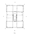
- Explanatory drawing showing the mounting position of a camera, and the imaging range of a camera.
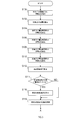
- the flowchart showing the procedure of the process which a rotation angle estimation apparatus performs.
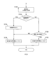
- the flowchart showing the procedure of the process which a rotation angle estimation apparatus performs.
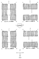
- Explanatory drawing showing the change of the picked-up image by the attitude
- the rotation angle estimation device 1 is an electronic control device mounted on a vehicle 2. This rotation angle estimation device 1 corresponds to the posture estimation device according to the present disclosure. As illustrated in FIG. 1, the rotation angle estimation device 1 is connected to cameras 20 a, 20 b, 20 c, 20 d, a gyro sensor 21, and a temperature sensor 22 that are devices mounted on the vehicle 2.
- the four cameras 20a to 20d are attached to the front, rear, left, and right of the vehicle 2 as a front camera, a rear camera, a left camera, and a right camera, respectively, so that the surroundings of the vehicle can be photographed. It has been.
- Each of the cameras 20a to 20d is for taking a picture of the surroundings of the vehicle 2 with the front, rear, left side, and right side of the vehicle 2 as respective shooting ranges, as exemplified by dotted lines in FIG.
- the shooting ranges of the respective cameras 20a to 20d include overlapping ranges 3, 4, 5, overlapping the shooting ranges of the adjacent cameras 20a to 20d in the left front, right front, left rear, and right rear portions of the vehicle 2. 6 is provided.
- the attachment positions and postures of the cameras 20a to 20d to the vehicle 2 are set in advance so that the imaging ranges of the cameras 20a to 20d are as described above. It is assumed that the actual mounting positions of the cameras 20a to 20d are adjusted at a manufacturing factory, a maintenance factory, or the like based on the set mounting position and posture (in other words, the shooting direction).
- the gyro sensor 21 is a known measuring instrument that detects the rotational angular velocity (for example, yaw rate, pitch rate, and / or roll rate) of the vehicle 2.
- the temperature sensor 22 is a known measuring instrument that measures the temperature around the vehicle 2. Measurement results obtained by the gyro sensor 21 and the temperature sensor 22 are input to the rotation angle estimation device 1.
- the rotation angle estimation device 1 is an information processing device mainly composed of a CPU, a RAM, a ROM, a semiconductor memory such as a flash memory (not shown), an input / output interface, and the like.
- the rotation angle estimation device 1 is embodied by, for example, a microcontroller or the like in which functions as a computer system are integrated.
- the function of the rotation angle estimation device 1 is realized by the CPU executing a program stored in a non-transitional physical storage medium such as a ROM or a semiconductor memory. Note that the number of microcontrollers constituting the rotation angle estimation device 1 may be one or plural.
- the rotation angle estimation device 1 has a function of estimating physical quantities such as a rotation angle and a rotation angular velocity representing the posture of the vehicle using captured images acquired by the cameras 20a to 20d.
- the rotation angle estimation device 1 includes a feature point detection unit 11, a posture estimation unit 12, a rotation angular velocity calculation unit 13, and a reliability determination unit 14.
- the method of realizing these elements constituting the rotation angle estimation device 1 is not limited to software, and some or all of the elements are realized using hardware that combines a logic circuit, an analog circuit, and the like. Also good.
- the rotation angle estimation device 1 performs viewpoint conversion of a plurality of captured images obtained by the respective cameras 20a to 20d using the attachment positions and orientations of the respective cameras 20a to 20d as camera parameters, so that a plurality of viewpoints above the vehicle 2 are formed.
- the camera parameters are, for example, values obtained by quantifying the attachment positions of the cameras 20a to 20d in the vehicle 2 and the attachment angles in the three axial directions of the vehicle 2 in the front, rear, left and right directions.
- the rotation angle estimation device 1 uses conversion data set based on the camera parameters when performing viewpoint conversion of the images captured by the cameras 20a to 20d.
- the rotation angle estimation apparatus 1 acquires a plurality of captured images acquired at the same time by the cameras 20a to 20d. Then, the rotation angle estimation device 1 detects the position of at least one feature point from the bird's-eye view image obtained by performing viewpoint conversion on each acquired captured image.
- the feature point here is an image portion in which a specific object on the road surface is captured.
- the object to be detected as the feature point can be easily distinguished from the road surface in the image, for example, paint drawn on the road, road fence, stone markings, road markings, manhole covers, etc. It is conceivable to use an object.
- the rotation angle estimation device 1 corrects the position shift of the feature point detected in S100.
- the deviation of the position of the feature point is a deviation caused by the deviation between the camera parameter and the actual mounting position and posture of each of the cameras 20a to 20b and the deviation of the center of gravity of the vehicle 2.
- known values separately measured by a known method using images acquired by the cameras 20a to 20b are used. To do.
- S100 and S102 correspond to processing as the feature point detection unit 11.
- the rotation angle estimation device 1 includes at least one of the bird's-eye images of the front camera 20a and the left camera 20c in an image region corresponding to the left front overlap range 3 among at least one feature point detected in S100. One feature point is extracted.
- the rotation angle estimation device 1 extracts the feature points included in the image area corresponding to the overlap area 4 on the right front among the feature points detected in S100 for each of the bird's-eye images of the front camera 20a and the right camera 20d. To do.
- the rotation angle estimation device 1 extracts the feature points included in the image region corresponding to the left rear overlap range 5 among the feature points detected in S100 for each of the bird's-eye images of the rear camera 20b and the left camera 20c. To do. In S110, the rotation angle estimation device 1 extracts the feature points included in the image region corresponding to the right rear overlapping range 6 among the feature points detected in S100 for each of the bird's-eye images of the rear camera 20b and the right camera 20d. To do.
- the rotation angle estimation device 1 determines the rotation angle representing the posture of the vehicle 2 based on the position of the feature point of each bird's-eye view image corresponding to each of the overlapping ranges 3 to 6 extracted in S104 to S110 (that is, the vehicle Estimate the rotation angle.
- the vehicle rotation angle estimated by the rotation angle estimation device 1 for example, a plurality of types of rotation angles such as a pitch angle, a roll angle, and a yaw angle are assumed.
- the relative positions of the cameras 20a to 20b with respect to the road surface as the subject change. For this reason, in the two cameras that capture the same overlapping range, the positions of the common feature points are shifted from each other. The degree of this shift differs depending on the position of the overlapping range with respect to the vehicle and the direction and degree of posture change.
- a is a bird's-eye view image of the left and right cameras 20 c and 20 d before the posture change occurs in the vehicle 2.
- b is a bird's-eye view of the front and rear cameras 20a and 20b acquired at the same time as a.
- c is a bird's-eye view image of the left and right cameras 20c and 20d at a stage where the pitch angle is changed so that the vehicle turns forward due to sudden deceleration.
- d is a bird's-eye view of the front and rear cameras 20a and 20b acquired at the same time as c.
- FIG. 5 it is assumed that a lane marking drawn along the road traveling direction is detected as a feature point.
- the front camera 20a is displaced more than the other cameras.
- a comparison is made between the bird's-eye view image c of the left and right cameras 20c and 20d and the bird's-eye view image d of the front camera 20a. Large differences occur.
- the rotation angle estimation device 1 compares the amount of deviation of the position of the feature point for each overlapping range between the front overlapping ranges 3 and 4 and the rear overlapping ranges 5 and 6, and based on the magnitude relationship. Estimate the pitch angle of the vehicle. Similarly, the amount of deviation of the position of the feature point for each overlapping range is compared between the left overlapping ranges 3 and 5 and the right overlapping ranges 4 and 6, and the vehicle is determined based on the magnitude relationship of the deviations. The roll angle can be estimated. Further, the yaw angle is estimated from the inclination of the lane markings detected from the cameras 20a to 20d with respect to the front-rear direction of the vehicle.
- next step S114 the rotation angle estimation device 1 determines whether or not a necessary number of time-series information of past vehicle rotation angles has been accumulated in a period from the current time to a predetermined time. When the required number of time series information of the vehicle rotation angle is not accumulated (that is, S114: NO), the rotation angle estimation device 1 advances the process to S118.
- the rotation angle estimation device 1 stores the vehicle rotation angle obtained in S112 in the memory as time-series information. On the other hand, when it is determined in S114 that the necessary number of time-series information of the vehicle rotation angle is accumulated (that is, S114: YES), the rotation angle estimation device 1 advances the process to S116.
- the rotation angle estimation device 1 calculates a vehicle rotation angular velocity that represents a time change rate of the vehicle rotation angle.
- the vehicle rotation angular velocity is calculated based on the vehicle rotation angle obtained in S112 and time-series information of past vehicle rotation angles accumulated in a period from the current time to a predetermined time.
- the vehicle rotational angular velocity is calculated, for example, as a value obtained by dividing the amount of change represented by the time series of the vehicle rotational angle by the elapsed time in the time series.
- a plurality of types of rotation angular velocities such as a pitch rate, a roll rate, and a yaw rate are assumed.
- the required number of past vehicle rotation angle information used for calculating the vehicle rotation angular velocity may be at least once, but may be a required number larger than that. For example, if the required number of information on the vehicle rotation angle is increased, the robustness of the calculation result of the vehicle rotation angular velocity against sudden noise is improved. On the other hand, the followability of the calculated vehicle rotational angular velocity becomes worse with respect to a sudden change in the vehicle rotational angle. On the other hand, if the required number of information on the vehicle rotation angle is reduced, the followability of the calculated vehicle rotation angular velocity with respect to a sudden change in the vehicle rotation angle is improved. On the other hand, the robustness of the calculation result of the vehicle rotation angular velocity against sudden noise is reduced. Therefore, the robustness and responsiveness of the calculation result of the vehicle rotation angular velocity are in a trade-off relationship depending on the required number of information on the vehicle rotation angle used for calculating the vehicle rotation angular velocity.
- the rotation angle estimation apparatus 1 executes the process of S118.
- the processing of S114 to S118 corresponds to the processing as the rotational angular velocity calculation unit 13.
- the rotation angle estimation device 1 calculates the difference between the vehicle angular velocity estimated in S116 and the latest measurement result by the gyro sensor 21. And the rotation angle estimation apparatus 1 memorize
- the rotation angle estimation device 1 is in a state in which the difference between the estimated vehicle angular velocity and the measurement result of the gyro sensor 21 is equal to or greater than a predetermined value for the comparison result of S120 stored in the period from the current time to the predetermined time. It is determined whether or not.
- the reliability of the gyro sensor 21 is determined. That is, if there is no significant difference between the vehicle rotational angular velocity estimated from the images of the cameras 20a to 20d and the vehicle rotational angular velocity measured by the gyro sensor 21, the gyro sensor 21 is functioning normally. To be judged. On the other hand, when the state where there is a difference between the vehicle rotational angular velocity estimated from the images of the cameras 20a to 20d and the vehicle rotational angular velocity measured by the gyro sensor 21 continues for a certain period, the reliability of the gyro sensor 21 Sex is denied.
- the rotation angle estimation device 1 advances the process to S124.
- S ⁇ b> 124 the rotation angle estimation device 1 outputs a failure notification, which is information indicating that the gyro sensor 21 is broken, to an output destination such as an output device (not shown) mounted on the vehicle 2.
- the rotation angle estimation apparatus 1 outputs the information on the vehicle rotation angle estimated in S112 and the information on the vehicle rotation angular velocity calculated in S116 as attitude information that is information representing the attitude of the vehicle 2.
- the rotation angle estimating apparatus 1 advances the process to S128.
- the rotation angle estimation device 1 determines whether or not the ambient temperature of the vehicle 2 is within an appropriate range based on the measurement result acquired from the temperature sensor 22.
- the appropriate range of the ambient temperature may be, for example, a temperature range in which the operation of the gyro sensor 21 is guaranteed.
- a gyro sensor mounted on a vehicle or the like has a poor measurement performance under extremely high or low temperature conditions. Therefore, in the present embodiment, it is configured to determine whether or not to adopt the measurement result by the gyro sensor 21 according to the ambient temperature in S122.
- the rotation angle estimation device 1 advances the process to S126.
- the rotation angle estimation apparatus 1 outputs the information on the vehicle rotation angle estimated in S112 and the information on the vehicle rotation angular velocity calculated in S116 as attitude information that is information representing the attitude of the vehicle 2.
- the rotation angle estimating apparatus 1 advances the process to S130.
- the rotation angle estimation device 1 outputs information on the vehicle rotation angular velocity detected by the gyro sensor 21 as posture information that is information representing the posture of the vehicle 2.
- the rotation angle estimation apparatus 1 detects feature points included in a region where the overlapping range is captured in the bird's-eye view images of the plurality of cameras 20a to 20c whose shooting ranges partially overlap. As a result, it is possible to estimate the vehicle rotation angle that represents the posture of the vehicle based on the deviation amount of the feature points for each of the plurality of overlapping ranges. For this reason, the rotation angle estimation device 1 can be substituted for the gyro sensor 21. Alternatively, by combining the rotation angle estimation device 1 and the gyro sensor 21, the means for detecting the attitude of the vehicle can be duplicated.
- the reliability of the gyro sensor 21 can be determined by comparing the vehicle posture estimated using the bird's-eye images of the cameras 20a to 20c and the vehicle posture measured by the gyro sensor 21. By doing so, for example, a failure notification of the gyro sensor 21 can be output under conditions in which the reliability of the gyro sensor 21 is denied. Further, it is possible to perform control such as invalidating the measurement result by the gyro sensor 21 from the viewpoint of fail-safe.
- the posture information based on the image and the posture information based on the measurement result of the gyro sensor 21 can be selectively output according to the ambient temperature. By doing in this way, suitable posture information can be output according to the environment of the vehicle. As a result, it contributes to improvement in the accuracy of posture information measurement.
- the feature point detection unit 11 corresponds to an example of an image acquisition unit and a detection unit.
- the posture estimation unit 12 and the rotational angular velocity calculation unit 13 correspond to an example of an estimation unit.
- the reliability determination unit 14 corresponds to an example of an attitude information output unit, a reliability information determination unit, a reliability information output unit, and an environment determination unit.
- the vehicle posture is estimated based on the images acquired by the four cameras 20a to 20d. Not only in this case, but on the condition that a plurality of overlapping ranges where a part of the shooting range overlaps each other is formed at a plurality of locations, the vehicle posture is determined based on images acquired by more or less than four cameras.
- the structure to estimate may be sufficient.
Abstract
A posture estimation device (1) acquires a plurality of images captured by a plurality of cameras (20a-20d) mounted on a vehicle so that overlapping ranges in which parts of imaging ranges overlap each other are formed in a plurality of areas. For the plurality of images, the posture estimation device detects a feature section included in the region of the images where the overlapping ranges are captured. Additionally, the posture estimation device calculates, for each overlapping range, the amount of deviation of the positions of the feature sections detected respectively from the plurality of images in which the overlapping ranges are shown, and the posture estimation device estimates the posture of the vehicle on the basis of the difference in the amount of deviation calculated for each of the plurality of overlapping ranges.
Description
本国際出願は、2016年9月15日に日本国特許庁に出願された日本国特許出願第2016-180480号に基づく優先権を主張するものであり、日本国特許出願第2016-180480号の全内容を本国際出願に参照により援用する。
This international application claims priority based on Japanese Patent Application No. 2016-180480 filed with the Japan Patent Office on September 15, 2016, and is based on Japanese Patent Application No. 2016-180480. The entire contents are incorporated by reference into this international application.
本開示は、車両に搭載されたカメラにより取得された画像に基づいて車両の姿勢を推定する姿勢推定装置に関する。
The present disclosure relates to a posture estimation device that estimates the posture of a vehicle based on an image acquired by a camera mounted on the vehicle.
特許文献1には、車載カメラによってそれぞれ異なる時刻に撮影された複数の画像を基に、車両の姿勢に関する回転角の一つであるピッチ角を推定する技術が記載されている。
Patent Document 1 describes a technique for estimating a pitch angle, which is one of rotation angles related to the attitude of a vehicle, based on a plurality of images taken at different times by an in-vehicle camera.
特許文献1に記載の技術は、車載カメラにより撮影された画像に基づいて車両のピッチ角を推定することが可能なものの、ロール角やヨー角等の車両の他の回転角を推定することは考慮されていない。発明者の詳細な検討の結果、特許文献1に記載の技術は、車両のピッチ角、ロール角及びヨー角等を含む総合的な姿勢を推定するには不十分であるという課題が見出された。
Although the technology described in Patent Document 1 can estimate the pitch angle of a vehicle based on an image taken by an in-vehicle camera, it is not possible to estimate other rotation angles of the vehicle such as a roll angle and a yaw angle. Not considered. As a result of detailed studies by the inventor, a problem has been found that the technique described in Patent Document 1 is insufficient to estimate the overall attitude including the pitch angle, roll angle, yaw angle, etc. of the vehicle. It was.
そこで、本開示の一局面は、車両に搭載されたカメラにより取得された画像に基づいて、車両の姿勢に関する様々な物理量を推定可能な技術を提供することが好ましい。
本開示の一態様に係る姿勢推定装置は、画像取得部と、検出部と、推定部と、姿勢情報出力部とを備える。 Therefore, it is preferable that one aspect of the present disclosure provides a technique capable of estimating various physical quantities related to the posture of the vehicle based on an image acquired by a camera mounted on the vehicle.
A posture estimation device according to an aspect of the present disclosure includes an image acquisition unit, a detection unit, an estimation unit, and a posture information output unit.
画像取得部は、車両に搭載された複数のカメラから、複数の画像を取得するように構成されている。これらの複数のカメラは、車両の周囲を撮影するためのものである。複数のカメラは、撮影範囲の一部が互いに重複する範囲である重複範囲が複数個所に形成されるように車両に搭載される。検出部は、画像取得部により同時期に取得された複数の画像のそれぞれについて、少なくとも1つの特徴部分を検出するように構成されている。特徴部分は、重複範囲が写された画像上の領域において所定の特徴を表す部分である。
The image acquisition unit is configured to acquire a plurality of images from a plurality of cameras mounted on the vehicle. The plurality of cameras are for photographing around the vehicle. The plurality of cameras are mounted on the vehicle so that overlapping ranges, which are ranges in which a part of the shooting ranges overlap each other, are formed at a plurality of locations. The detection unit is configured to detect at least one feature portion of each of the plurality of images acquired at the same time by the image acquisition unit. The feature portion is a portion representing a predetermined feature in an area on the image where the overlapping range is copied.
推定部は、検出部により検出された特徴部分に基づいて車両の姿勢に関する所定の物理量を推定するように構成されている。具体的には、推定部は、個々の重複範囲ごとに、当該重複範囲を写した複数の画像それぞれから検出された特徴部分同士の位置のずれ量を算出する。そして、推定部は、複数の重複範囲それぞれについて算出されたずれ量の相違に基づいて、車両の姿勢に関する所定の物理量を推定する。姿勢情報出力部は、車両の姿勢を表す情報である姿勢情報として、推定部によって推定された物理量に基づく情報を出力するように構成されている。
The estimation unit is configured to estimate a predetermined physical quantity related to the posture of the vehicle based on the feature portion detected by the detection unit. Specifically, the estimation unit calculates, for each overlapped range, a positional shift amount between the feature portions detected from each of a plurality of images in which the overlapped range is copied. Then, the estimation unit estimates a predetermined physical quantity related to the posture of the vehicle based on the difference in deviation amount calculated for each of the plurality of overlapping ranges. The attitude information output unit is configured to output information based on the physical quantity estimated by the estimation unit as attitude information that is information representing the attitude of the vehicle.
車両に複数のカメラが搭載されている場合、車両の姿勢が変化することにより各カメラが変位すると、車両の姿勢の変化の方向や程度に応じて重複する各カメラの撮影範囲に映る物体の位置が互いにずれる。そこで、本開示に係る姿勢推定装置では、撮影範囲が一部重複する複数のカメラにより取得された画像における重複範囲に該当する領域に含まれる特徴部分を検出する。そして、複数の重複範囲ごとの特徴部分の位置のずれ量に基づいて車両の姿勢を推定する。このようにすることで、車両の姿勢に関する様々な物理量を推定可能な技術を実現できる。
When multiple cameras are mounted on a vehicle, if each camera is displaced due to a change in the posture of the vehicle, the position of the object that appears in the shooting range of each camera that overlaps depending on the direction and degree of the change in the posture of the vehicle Deviate from each other. Therefore, in the posture estimation apparatus according to the present disclosure, a feature portion included in a region corresponding to the overlapping range in an image acquired by a plurality of cameras having a partially overlapping shooting range is detected. And the attitude | position of a vehicle is estimated based on the deviation | shift amount of the position of the characteristic part for every some overlapping range. By doing in this way, the technique which can estimate various physical quantities regarding the attitude | position of a vehicle is realizable.
本開示についての上記目的及びその他の目的、特徴や利点は、添付の図面を参照しながら下記の詳細な記述により、より明確になる。その図面の概要は次のとおりである。
実施形態の回転角推定装置の構成を表すブロック図。
カメラの搭載位置、及びカメラの撮影範囲を表す説明図。
回転角推定装置が実行する処理の手順を表すフローチャート。
回転角推定装置が実行する処理の手順を表すフローチャート。
車両の姿勢変化による撮影画像の変化を表す説明図。
The above and other objects, features, and advantages of the present disclosure will become more apparent from the following detailed description with reference to the accompanying drawings. The outline of the drawing is as follows.
The block diagram showing the structure of the rotation angle estimation apparatus of embodiment. Explanatory drawing showing the mounting position of a camera, and the imaging range of a camera. The flowchart showing the procedure of the process which a rotation angle estimation apparatus performs. The flowchart showing the procedure of the process which a rotation angle estimation apparatus performs. Explanatory drawing showing the change of the picked-up image by the attitude | position change of a vehicle.
以下、本開示の実施形態を図面に基づいて説明する。なお、本開示は下記の実施形態に限定されるものではなく様々な態様にて実施することが可能である。
[回転角推定装置の構成の説明]
実施形態の回転角推定装置1は、車両2に搭載される電子制御装置である。この回転角推定装置1が、本開示における姿勢推定装置に相当する。図1に例示されるとおり、回転角推定装置1は、車両2に搭載された機器であるカメラ20a,20b,20c,20d、ジャイロセンサ21、及び温度センサ22と接続されている。 Hereinafter, embodiments of the present disclosure will be described with reference to the drawings. In addition, this indication is not limited to the following embodiment, It is possible to implement in various aspects.
[Description of Configuration of Rotation Angle Estimation Device]
The rotationangle estimation device 1 according to the embodiment is an electronic control device mounted on a vehicle 2. This rotation angle estimation device 1 corresponds to the posture estimation device according to the present disclosure. As illustrated in FIG. 1, the rotation angle estimation device 1 is connected to cameras 20 a, 20 b, 20 c, 20 d, a gyro sensor 21, and a temperature sensor 22 that are devices mounted on the vehicle 2.
[回転角推定装置の構成の説明]
実施形態の回転角推定装置1は、車両2に搭載される電子制御装置である。この回転角推定装置1が、本開示における姿勢推定装置に相当する。図1に例示されるとおり、回転角推定装置1は、車両2に搭載された機器であるカメラ20a,20b,20c,20d、ジャイロセンサ21、及び温度センサ22と接続されている。 Hereinafter, embodiments of the present disclosure will be described with reference to the drawings. In addition, this indication is not limited to the following embodiment, It is possible to implement in various aspects.
[Description of Configuration of Rotation Angle Estimation Device]
The rotation
図2に例示されるとおり、4つのカメラ20a~20dは、車両周囲を撮影できるように、前カメラ、後カメラ、左カメラ、右カメラとして、車両2の前、後、左、右にそれぞれ取付けられている。各カメラ20a~20dは、図2において点線で例示されるように、車両2の前方、後方、左側方、右側方をそれぞれの撮影範囲として、車両周囲を撮影するためのものである。そして、各カメラ20a~20dの撮影範囲には、車両2の左前方、右前方、左後方、右後方の各部において互いに隣接するカメラ20a~20dの撮影範囲と重なる重複範囲3,4,5,6が設けられている。
As illustrated in FIG. 2, the four cameras 20a to 20d are attached to the front, rear, left, and right of the vehicle 2 as a front camera, a rear camera, a left camera, and a right camera, respectively, so that the surroundings of the vehicle can be photographed. It has been. Each of the cameras 20a to 20d is for taking a picture of the surroundings of the vehicle 2 with the front, rear, left side, and right side of the vehicle 2 as respective shooting ranges, as exemplified by dotted lines in FIG. The shooting ranges of the respective cameras 20a to 20d include overlapping ranges 3, 4, 5, overlapping the shooting ranges of the adjacent cameras 20a to 20d in the left front, right front, left rear, and right rear portions of the vehicle 2. 6 is provided.
また、各カメラ20a~20dの車両2への取付位置及び姿勢は、各カメラ20a~20dの撮像範囲が上記のようになるように予め設定されている。そして、各カメラ20a~20dの実際の搭載位置は、その設定された取付位置及び姿勢(換言すれば、撮影方向)に基づいて製造工場や整備工場等で調節されているものとする。
Also, the attachment positions and postures of the cameras 20a to 20d to the vehicle 2 are set in advance so that the imaging ranges of the cameras 20a to 20d are as described above. It is assumed that the actual mounting positions of the cameras 20a to 20d are adjusted at a manufacturing factory, a maintenance factory, or the like based on the set mounting position and posture (in other words, the shooting direction).
図1のブロック図の説明に戻る。ジャイロセンサ21は、車両2の回転角速度(例えば、ヨーレート、ピッチレート、及び/又はロールレート)を検知する公知の計測器である。温度センサ22は、車両2の周囲の気温を計測する公知の計測器である。これらのジャイロセンサ21及び温度センサ22による計測結果が、回転角推定装置1に入力される。
Returning to the block diagram of FIG. The gyro sensor 21 is a known measuring instrument that detects the rotational angular velocity (for example, yaw rate, pitch rate, and / or roll rate) of the vehicle 2. The temperature sensor 22 is a known measuring instrument that measures the temperature around the vehicle 2. Measurement results obtained by the gyro sensor 21 and the temperature sensor 22 are input to the rotation angle estimation device 1.
回転角推定装置1は、図示しないCPU、RAM、ROM、フラッシュメモリ等の半導体メモリ、及び入出力インタフェース等を中心に構成された情報処理装置である。回転角推定装置1は、例えば、コンピュータシステムとしての機能が集約されたマイクロコントローラ等により具現化される。回転角推定装置1の機能は、CPUがROMや半導体メモリ等の非遷移的実体的記憶媒体に格納されたプログラムを実行することにより実現される。なお、回転角推定装置1を構成するマイクロコントローラの数は1つでも複数でもよい。
The rotation angle estimation device 1 is an information processing device mainly composed of a CPU, a RAM, a ROM, a semiconductor memory such as a flash memory (not shown), an input / output interface, and the like. The rotation angle estimation device 1 is embodied by, for example, a microcontroller or the like in which functions as a computer system are integrated. The function of the rotation angle estimation device 1 is realized by the CPU executing a program stored in a non-transitional physical storage medium such as a ROM or a semiconductor memory. Note that the number of microcontrollers constituting the rotation angle estimation device 1 may be one or plural.
回転角推定装置1は、各カメラ20a~20dにより取得された撮像画像を利用して、車両の姿勢を表す回転角及び回転角速度等の物理量を推定する機能を備える。当該機能の構成要素として、回転角推定装置1は、特徴点検出部11と、姿勢推定部12と、回転角速度算出部13と、信頼性判定部14とを備える。なお、回転角推定装置1を構成するこれらの要素を実現する手法はソフトウェアに限るものではなく、その一部又は全部の要素を論理回路やアナログ回路等を組合せたハードウェアを用いて実現してもよい。
The rotation angle estimation device 1 has a function of estimating physical quantities such as a rotation angle and a rotation angular velocity representing the posture of the vehicle using captured images acquired by the cameras 20a to 20d. As components of the function, the rotation angle estimation device 1 includes a feature point detection unit 11, a posture estimation unit 12, a rotation angular velocity calculation unit 13, and a reliability determination unit 14. Note that the method of realizing these elements constituting the rotation angle estimation device 1 is not limited to software, and some or all of the elements are realized using hardware that combines a logic circuit, an analog circuit, and the like. Also good.
また、回転角推定装置1は、各カメラ20a~20dの取付位置及び姿勢をカメラパラメータとして、各カメラ20a~20dによる複数の撮像画像を視点変換することで、車両2の上方の視点からなる複数の鳥瞰画像を生成する機能を有する。なお、カメラパラメータは、例えば、各カメラ20a~20dの車両2における取付位置、及び車両2の前後、左右、上下の3軸方向の取付角度を数値化したものである。そして、回転角推定装置1は、各カメラ20a~20dによる撮像画像を視点変換する際には、カメラパラメータに基づいて設定された変換データを利用する。
Further, the rotation angle estimation device 1 performs viewpoint conversion of a plurality of captured images obtained by the respective cameras 20a to 20d using the attachment positions and orientations of the respective cameras 20a to 20d as camera parameters, so that a plurality of viewpoints above the vehicle 2 are formed. Has a function of generating a bird's-eye view image. The camera parameters are, for example, values obtained by quantifying the attachment positions of the cameras 20a to 20d in the vehicle 2 and the attachment angles in the three axial directions of the vehicle 2 in the front, rear, left and right directions. The rotation angle estimation device 1 uses conversion data set based on the camera parameters when performing viewpoint conversion of the images captured by the cameras 20a to 20d.
[回転角推定装置が実行する処理の説明]
回転角推定装置1が実行する処理の手順について、図3及び図4のフローチャートを参照しながら説明する。この処理は、所定の制御周期ごとに繰返し実行される。 [Description of processing executed by rotation angle estimation device]
A procedure of processing executed by the rotationangle estimation device 1 will be described with reference to the flowcharts of FIGS. 3 and 4. This process is repeatedly executed every predetermined control cycle.
回転角推定装置1が実行する処理の手順について、図3及び図4のフローチャートを参照しながら説明する。この処理は、所定の制御周期ごとに繰返し実行される。 [Description of processing executed by rotation angle estimation device]
A procedure of processing executed by the rotation
まず、図3のフローチャートから説明する。S100では、回転角推定装置1は、各カメラ20a~20dにより同時期に取得された複数の撮像画像を取得する。そして、回転角推定装置1は、その取得した各撮像画像をそれぞれ視点変換した鳥瞰画像から、少なくとも1つの特徴点の位置を検出する。ここでいう特徴点とは、路面上の特定の対象物が写された画像部分である。ここで、特徴点として検出する対象物としては、例えば、道路上に描かれたペイント、道路鋲、石等による区画線や道路標示、あるいはマンホールの蓋等、画像において路面との区別が容易な対象物を利用することが考えられる。
First, the flowchart of FIG. 3 will be described. In S100, the rotation angle estimation apparatus 1 acquires a plurality of captured images acquired at the same time by the cameras 20a to 20d. Then, the rotation angle estimation device 1 detects the position of at least one feature point from the bird's-eye view image obtained by performing viewpoint conversion on each acquired captured image. The feature point here is an image portion in which a specific object on the road surface is captured. Here, the object to be detected as the feature point can be easily distinguished from the road surface in the image, for example, paint drawn on the road, road fence, stone markings, road markings, manhole covers, etc. It is conceivable to use an object.
S102では、回転角推定装置1は、S100において検出された特徴点の位置のずれを補正する。特徴点の位置のずれは、カメラパラメータと実際の各カメラ20a~20bの取付位置及び姿勢とのずれ、及び車両2の重心の偏りに起因するずれである。各カメラ20a~20bの取付位置及び姿勢のずれや、重心の偏りについては、例えば、各カメラ20a~20bにより取得された画像を用いる周知の手法により別途測定された既知の値を利用するものとする。なお、S100及びS102が、特徴点検出部11としての処理に相当する。
In S102, the rotation angle estimation device 1 corrects the position shift of the feature point detected in S100. The deviation of the position of the feature point is a deviation caused by the deviation between the camera parameter and the actual mounting position and posture of each of the cameras 20a to 20b and the deviation of the center of gravity of the vehicle 2. Regarding the displacement of the mounting positions and postures of the cameras 20a to 20b and the deviation of the center of gravity, for example, known values separately measured by a known method using images acquired by the cameras 20a to 20b are used. To do. Note that S100 and S102 correspond to processing as the feature point detection unit 11.
S104では、回転角推定装置1は、前カメラ20a及び左カメラ20cの鳥瞰画像それぞれについて、S100で検出された少なくとも1つの特徴点のうち左前方の重複範囲3に対応する画像領域に含まれる少なくとも1つの特徴点を抽出する。S106では、回転角推定装置1は、前カメラ20a及び右カメラ20dの鳥瞰画像それぞれについて、S100で検出された特徴点のうち右前方の重複範囲4に対応する画像領域に含まれる特徴点を抽出する。
In S104, the rotation angle estimation device 1 includes at least one of the bird's-eye images of the front camera 20a and the left camera 20c in an image region corresponding to the left front overlap range 3 among at least one feature point detected in S100. One feature point is extracted. In S106, the rotation angle estimation device 1 extracts the feature points included in the image area corresponding to the overlap area 4 on the right front among the feature points detected in S100 for each of the bird's-eye images of the front camera 20a and the right camera 20d. To do.
S108では、回転角推定装置1は、後カメラ20b及び左カメラ20cの鳥瞰画像それぞれについて、S100で検出された特徴点のうち左後方の重複範囲5に対応する画像領域に含まれる特徴点を抽出する。S110では、回転角推定装置1は、後カメラ20b及び右カメラ20dの鳥瞰画像それぞれについて、S100で検出された特徴点のうち右後方の重複範囲6に対応する画像領域に含まれる特徴点を抽出する。
In S108, the rotation angle estimation device 1 extracts the feature points included in the image region corresponding to the left rear overlap range 5 among the feature points detected in S100 for each of the bird's-eye images of the rear camera 20b and the left camera 20c. To do. In S110, the rotation angle estimation device 1 extracts the feature points included in the image region corresponding to the right rear overlapping range 6 among the feature points detected in S100 for each of the bird's-eye images of the rear camera 20b and the right camera 20d. To do.
S112では、回転角推定装置1は、S104~S110において抽出された各重複範囲3~6に対応する各鳥瞰画像の特徴点の位置に基づいて、車両2の姿勢を表す回転角(すなわち、車両回転角)を推定する。本実施形態では、回転角推定装置1が推定する車両回転角として、例えば、ピッチ角、ロール角、及びヨー角等の複数種類の回転角を想定している。
In S112, the rotation angle estimation device 1 determines the rotation angle representing the posture of the vehicle 2 based on the position of the feature point of each bird's-eye view image corresponding to each of the overlapping ranges 3 to 6 extracted in S104 to S110 (that is, the vehicle Estimate the rotation angle. In the present embodiment, as the vehicle rotation angle estimated by the rotation angle estimation device 1, for example, a plurality of types of rotation angles such as a pitch angle, a roll angle, and a yaw angle are assumed.
車両の加速、減速、及び/又は旋回による回転力が加わることで車両の姿勢が変化すると、被写体である路面に対する各カメラ20a~20bの相対的な位置が変化する。このため、同じ重複範囲を写す2つのカメラにおいて、共通の特徴点の位置が互いにずれる。このずれは、車両に対する重複範囲の位置と、姿勢変化の方向及び程度とに応じて程度が異なる。
When the vehicle posture changes due to the application of rotational force due to acceleration, deceleration and / or turning of the vehicle, the relative positions of the cameras 20a to 20b with respect to the road surface as the subject change. For this reason, in the two cameras that capture the same overlapping range, the positions of the common feature points are shifted from each other. The degree of this shift differs depending on the position of the overlapping range with respect to the vehicle and the direction and degree of posture change.
具体例について図5を参照しながら説明する。図5において、aは、車両2に姿勢変化が生じる前の段階における左右カメラ20c及び20dの鳥瞰画像である。bは、aと同時期に取得された前後カメラ20a及び20bの鳥瞰図である。また、cは、急減速により車両が前のめりになるようにピッチ角が変化した段階における左右カメラ20c及び20dの鳥瞰画像である。dは、cと同時期に取得された前後カメラ20a及び20bの鳥瞰図である。なお、図5の事例では、特徴点として道路の進行方向に沿って引かれた区画線が検出されていることを前提とする。
A specific example will be described with reference to FIG. In FIG. 5, a is a bird's-eye view image of the left and right cameras 20 c and 20 d before the posture change occurs in the vehicle 2. b is a bird's-eye view of the front and rear cameras 20a and 20b acquired at the same time as a. Further, c is a bird's-eye view image of the left and right cameras 20c and 20d at a stage where the pitch angle is changed so that the vehicle turns forward due to sudden deceleration. d is a bird's-eye view of the front and rear cameras 20a and 20b acquired at the same time as c. In the case of FIG. 5, it is assumed that a lane marking drawn along the road traveling direction is detected as a feature point.
急減速により車両が前のめりになるようにピッチ角が変化すると、前カメラ20aが他のカメラより大きく変位することになる。この場合、図5に例示されるとおり、左右カメラ20c及び20dの鳥瞰画像cと前カメラ20aの鳥瞰画像dとの間で、重複範囲3及び4における特徴点である区画線の写り方に比較的大きな差異が生じる。
If the pitch angle changes so that the vehicle turns forward due to sudden deceleration, the front camera 20a is displaced more than the other cameras. In this case, as illustrated in FIG. 5, a comparison is made between the bird's-eye view image c of the left and right cameras 20c and 20d and the bird's-eye view image d of the front camera 20a. Large differences occur.
一方、車両が前のめりになるように姿勢変化した場合、後カメラ20bは前カメラ20aと比較して変位が小さい。このため、図5に例示されるとおり、左右カメラ20c及び20dの鳥瞰画像cと後カメラ20bの鳥瞰画像dとの間で、重複範囲5及び6における特徴点である区画線の写り方には、それ程大きな差異は生じていない。
On the other hand, when the posture of the vehicle is changed so that the vehicle is turned forward, the rear camera 20b is less displaced than the front camera 20a. For this reason, as illustrated in FIG. 5, between the bird's-eye view image c of the left and right cameras 20 c and 20 d and the bird's-eye view image d of the rear camera 20 b, , So much difference has not occurred.
そこで、回転角推定装置1は、前側の重複範囲3,4と後側の重複範囲5,6との間で重複範囲ごとの特徴点の位置のずれ量を比較し、その大小関係に基づいて車両のピッチ角を推定する。また、同様にして、左側の重複範囲3,5と右側の重複範囲4,6との間で重複範囲ごとの特徴点の位置のずれ量を比較し、そのずれ量の大小関係に基づいて車両のロール角を推定することができる。また、ヨー角については、各カメラ20a~20dから検出された区画線の、車両の前後方向に対する傾きから推定する。
Therefore, the rotation angle estimation device 1 compares the amount of deviation of the position of the feature point for each overlapping range between the front overlapping ranges 3 and 4 and the rear overlapping ranges 5 and 6, and based on the magnitude relationship. Estimate the pitch angle of the vehicle. Similarly, the amount of deviation of the position of the feature point for each overlapping range is compared between the left overlapping ranges 3 and 5 and the right overlapping ranges 4 and 6, and the vehicle is determined based on the magnitude relationship of the deviations. The roll angle can be estimated. Further, the yaw angle is estimated from the inclination of the lane markings detected from the cameras 20a to 20d with respect to the front-rear direction of the vehicle.
図3のフローチャートの説明に戻る。上記S104~S112の処理が、姿勢推定部12としての処理に相当する。次のS114では、回転角推定装置1は、現時点から所定時間前までの期間において過去の車両回転角の時系列の情報が必要数蓄積されているか否かを判定する。車両回転角の時系列の情報が必要数蓄積されていない場合(すなわち、S114:NO)、回転角推定装置1は処理をS118に進める。
Returning to the flowchart of FIG. The processes in S104 to S112 correspond to the process as the posture estimation unit 12. In next step S114, the rotation angle estimation device 1 determines whether or not a necessary number of time-series information of past vehicle rotation angles has been accumulated in a period from the current time to a predetermined time. When the required number of time series information of the vehicle rotation angle is not accumulated (that is, S114: NO), the rotation angle estimation device 1 advances the process to S118.
S118では、回転角推定装置1は、S112で得られた車両回転角を時系列の情報としてメモリに蓄積する。一方、S114において車両回転角の時系列の情報が必要数蓄積されていると判定された場合(すなわち、S114:YES)、回転角推定装置1は処理をS116に進める。
In S118, the rotation angle estimation device 1 stores the vehicle rotation angle obtained in S112 in the memory as time-series information. On the other hand, when it is determined in S114 that the necessary number of time-series information of the vehicle rotation angle is accumulated (that is, S114: YES), the rotation angle estimation device 1 advances the process to S116.
S116では、回転角推定装置1は、車両回転角の時間変化率を表す車両回転角速度を算出する。車両回転角速度は、S112で得られた車両回転角、及び現時点から所定時間前までの期間において蓄積された過去の車両回転角の時系列の情報に基づいて算出される。車両回転角速度は、例えば、車両回転角の時系列で表される変化量を、当該時系列における経過時間で除した値として算出される。本実施形態において回転角推定装置1が推定する車両回転角速度として、例えば、ピッチレート、ロールレート、及びヨーレート等の複数種類の回転角速度を想定している。
In S116, the rotation angle estimation device 1 calculates a vehicle rotation angular velocity that represents a time change rate of the vehicle rotation angle. The vehicle rotation angular velocity is calculated based on the vehicle rotation angle obtained in S112 and time-series information of past vehicle rotation angles accumulated in a period from the current time to a predetermined time. The vehicle rotational angular velocity is calculated, for example, as a value obtained by dividing the amount of change represented by the time series of the vehicle rotational angle by the elapsed time in the time series. In the present embodiment, as the vehicle rotation angular velocity estimated by the rotation angle estimation device 1, for example, a plurality of types of rotation angular velocities such as a pitch rate, a roll rate, and a yaw rate are assumed.
なお、車両回転角速度を算出するために用いる過去の車両回転角の情報の必要数は、最低限1回分あればよいが、それよりも多くの必要数としてもよい。例えば、車両回転角の情報の必要数を多くすれば、突発的なノイズに対する車両回転角速度の算出結果のロバスト性が向上する。反面、車両回転角の急激な変化に対して、算出される車両回転角速度の追従性が悪くなる。一方、車両回転角の情報の必要数を少なくすれば、車両回転角の急激な変化に対して、算出される車両回転角速度の追従性が向上する。反面、突発的なノイズに対する車両回転角速度の算出結果のロバスト性が低下する。よって、車両回転角速度の算出結果のロバスト性と応答性とは、車両回転角速度の算出に用いる車両回転角の情報の必要数に応じてトレードオフの関係となる。
Note that the required number of past vehicle rotation angle information used for calculating the vehicle rotation angular velocity may be at least once, but may be a required number larger than that. For example, if the required number of information on the vehicle rotation angle is increased, the robustness of the calculation result of the vehicle rotation angular velocity against sudden noise is improved. On the other hand, the followability of the calculated vehicle rotational angular velocity becomes worse with respect to a sudden change in the vehicle rotational angle. On the other hand, if the required number of information on the vehicle rotation angle is reduced, the followability of the calculated vehicle rotation angular velocity with respect to a sudden change in the vehicle rotation angle is improved. On the other hand, the robustness of the calculation result of the vehicle rotation angular velocity against sudden noise is reduced. Therefore, the robustness and responsiveness of the calculation result of the vehicle rotation angular velocity are in a trade-off relationship depending on the required number of information on the vehicle rotation angle used for calculating the vehicle rotation angular velocity.
S116の後、回転角推定装置1はS118の処理を実行する。なお、S114~S118の処理が、回転角速度算出部13としての処理に相当する。
図4のフローチャートの説明に移る。120では、回転角推定装置1は、S116において推定された車両角速度とジャイロセンサ21による最新の測定結果との差分を算出する。そして、回転角推定装置1は、その算出した差分を比較結果として記憶する。S122では、回転角推定装置1は、現時点から所定時間前までの期間において記憶されたS120の比較結果について、推定された車両角速度とジャイロセンサ21の測定結果との差分が所定値以上である状態が連続している否かを判定する。 After S116, the rotationangle estimation apparatus 1 executes the process of S118. Note that the processing of S114 to S118 corresponds to the processing as the rotational angular velocity calculation unit 13.
Turning to the flowchart of FIG. In 120, the rotationangle estimation device 1 calculates the difference between the vehicle angular velocity estimated in S116 and the latest measurement result by the gyro sensor 21. And the rotation angle estimation apparatus 1 memorize | stores the calculated difference as a comparison result. In S122, the rotation angle estimation device 1 is in a state in which the difference between the estimated vehicle angular velocity and the measurement result of the gyro sensor 21 is equal to or greater than a predetermined value for the comparison result of S120 stored in the period from the current time to the predetermined time. It is determined whether or not.
図4のフローチャートの説明に移る。120では、回転角推定装置1は、S116において推定された車両角速度とジャイロセンサ21による最新の測定結果との差分を算出する。そして、回転角推定装置1は、その算出した差分を比較結果として記憶する。S122では、回転角推定装置1は、現時点から所定時間前までの期間において記憶されたS120の比較結果について、推定された車両角速度とジャイロセンサ21の測定結果との差分が所定値以上である状態が連続している否かを判定する。 After S116, the rotation
Turning to the flowchart of FIG. In 120, the rotation
このS122では、ジャイロセンサ21の信頼性が判定される。すなわち、各カメラ20a~20dの画像から推定された車両回転角速度と、ジャイロセンサ21により測定された車両回転角速度との間に顕著な差がなければ、ジャイロセンサ21が正常に機能していると判断される。一方、各カメラ20a~20dの画像から推定された車両回転角速度と、ジャイロセンサ21により測定された車両回転角速度との間に差がある状態が一定期間連続している場合、ジャイロセンサ21の信頼性が否定される。
In S122, the reliability of the gyro sensor 21 is determined. That is, if there is no significant difference between the vehicle rotational angular velocity estimated from the images of the cameras 20a to 20d and the vehicle rotational angular velocity measured by the gyro sensor 21, the gyro sensor 21 is functioning normally. To be judged. On the other hand, when the state where there is a difference between the vehicle rotational angular velocity estimated from the images of the cameras 20a to 20d and the vehicle rotational angular velocity measured by the gyro sensor 21 continues for a certain period, the reliability of the gyro sensor 21 Sex is denied.
比較結果の差分が所定値以上である状態が一定期間連続している場合(すなわち、S122:YES)、回転角推定装置1は処理をS124に進める。S124では、回転角推定装置1は、ジャイロセンサ21が故障していることを表す情報である故障通知を、車両2に搭載された図示しない出力装置等の出力先に出力する。S126では、回転角推定装置1は、S112において推定された車両回転角の情報、及びS116において算出された車両回転角速度の情報を、車両2の姿勢を表す情報である姿勢情報として出力する。
When the state where the difference between the comparison results is equal to or greater than the predetermined value continues for a certain period of time (ie, S122: YES), the rotation angle estimation device 1 advances the process to S124. In S <b> 124, the rotation angle estimation device 1 outputs a failure notification, which is information indicating that the gyro sensor 21 is broken, to an output destination such as an output device (not shown) mounted on the vehicle 2. In S126, the rotation angle estimation apparatus 1 outputs the information on the vehicle rotation angle estimated in S112 and the information on the vehicle rotation angular velocity calculated in S116 as attitude information that is information representing the attitude of the vehicle 2.
一方、S122において比較結果の差分が所定値以上である状態が連続していないと判定された場合(すなわち、S122:NO)、回転角推定装置1は処理をS128に進める。S128では、回転角推定装置1は、温度センサ22から取得した測定結果に基づいて、車両2の周囲温度が適正範囲内であるか否かを判定する。
On the other hand, when it is determined in S122 that the difference in the comparison result is equal to or greater than the predetermined value is not continuous (that is, S122: NO), the rotation angle estimating apparatus 1 advances the process to S128. In S128, the rotation angle estimation device 1 determines whether or not the ambient temperature of the vehicle 2 is within an appropriate range based on the measurement result acquired from the temperature sensor 22.
なお、周囲温度の適正範囲は、例えば、ジャイロセンサ21の動作が保証された温度範囲とすることが考えられる。一般的に、車両等に搭載されるジャイロセンサは、極端な高温又は低温の条件下において測定性能が低下することが知られている。そこで、本実施形態では、S122において周囲温度に応じてジャイロセンサ21による測定結果を採用するか否かが判定されるように構成されている。
Note that the appropriate range of the ambient temperature may be, for example, a temperature range in which the operation of the gyro sensor 21 is guaranteed. In general, it is known that a gyro sensor mounted on a vehicle or the like has a poor measurement performance under extremely high or low temperature conditions. Therefore, in the present embodiment, it is configured to determine whether or not to adopt the measurement result by the gyro sensor 21 according to the ambient temperature in S122.
周囲温度が適正範囲外である場合(すなわち、S128:NO)、回転角推定装置1は処理をS126に進める。S126では、回転角推定装置1は、S112において推定された車両回転角の情報、及びS116において算出された車両回転角速度の情報を、車両2の姿勢を表す情報である姿勢情報として出力する。
When the ambient temperature is outside the appropriate range (that is, S128: NO), the rotation angle estimation device 1 advances the process to S126. In S126, the rotation angle estimation apparatus 1 outputs the information on the vehicle rotation angle estimated in S112 and the information on the vehicle rotation angular velocity calculated in S116 as attitude information that is information representing the attitude of the vehicle 2.
一方、周囲温度が適正範囲内である場合(すなわち、S128:YES)、回転角推定装置1は処理をS130に進める。S130では、回転角推定装置1は、ジャイロセンサ21により検出された車両回転角速度の情報を、車両2の姿勢を表す情報である姿勢情報として出力する。
On the other hand, when the ambient temperature is within the appropriate range (that is, S128: YES), the rotation angle estimating apparatus 1 advances the process to S130. In S <b> 130, the rotation angle estimation device 1 outputs information on the vehicle rotation angular velocity detected by the gyro sensor 21 as posture information that is information representing the posture of the vehicle 2.
[効果]
実施形態の回転角推定装置1によれば、以下の効果を奏する。
回転角推定装置1は、撮影範囲が一部重複する複数のカメラ20a~20cの鳥瞰画像において、重複範囲が写る領域に含まれる特徴点を検出する。その結果、複数の重複範囲ごとの特徴点のずれ量に基づいて車両の姿勢を表す車両回転角を推定することができる。このため、回転角推定装置1は、ジャイロセンサ21の代替となり得る。あるいは、回転角推定装置1とジャイロセンサ21とを組合せることにより、車両の姿勢を検知する手段を二重化することができる。 [effect]
According to the rotationangle estimation device 1 of the embodiment, the following effects are obtained.
The rotationangle estimation apparatus 1 detects feature points included in a region where the overlapping range is captured in the bird's-eye view images of the plurality of cameras 20a to 20c whose shooting ranges partially overlap. As a result, it is possible to estimate the vehicle rotation angle that represents the posture of the vehicle based on the deviation amount of the feature points for each of the plurality of overlapping ranges. For this reason, the rotation angle estimation device 1 can be substituted for the gyro sensor 21. Alternatively, by combining the rotation angle estimation device 1 and the gyro sensor 21, the means for detecting the attitude of the vehicle can be duplicated.
実施形態の回転角推定装置1によれば、以下の効果を奏する。
回転角推定装置1は、撮影範囲が一部重複する複数のカメラ20a~20cの鳥瞰画像において、重複範囲が写る領域に含まれる特徴点を検出する。その結果、複数の重複範囲ごとの特徴点のずれ量に基づいて車両の姿勢を表す車両回転角を推定することができる。このため、回転角推定装置1は、ジャイロセンサ21の代替となり得る。あるいは、回転角推定装置1とジャイロセンサ21とを組合せることにより、車両の姿勢を検知する手段を二重化することができる。 [effect]
According to the rotation
The rotation
また、カメラ20a~20cの鳥瞰画像を用いて推定された車両姿勢と、ジャイロセンサ21により測定された車両姿勢とを比較することにより、ジャイロセンサ21の信頼性を判定することができる。このようにすることで、例えば、ジャイロセンサ21の信頼性が否定された条件下において、ジャイロセンサ21の故障通知を出力することができる。また、フェールセーフの観点からジャイロセンサ21による測定結果を無効にするといった制御を行うことが可能になる。
Further, the reliability of the gyro sensor 21 can be determined by comparing the vehicle posture estimated using the bird's-eye images of the cameras 20a to 20c and the vehicle posture measured by the gyro sensor 21. By doing so, for example, a failure notification of the gyro sensor 21 can be output under conditions in which the reliability of the gyro sensor 21 is denied. Further, it is possible to perform control such as invalidating the measurement result by the gyro sensor 21 from the viewpoint of fail-safe.
また、周囲温度に応じて、画像に基づく姿勢情報と、ジャイロセンサ21の測定結果に基づく姿勢情報とを選択的に出力することができる。このようにすることで、車両の環境に応じて好適な方の姿勢情報を出力することができる。その結果、姿勢情報の測定精度の向上に寄与する。
Also, the posture information based on the image and the posture information based on the measurement result of the gyro sensor 21 can be selectively output according to the ambient temperature. By doing in this way, suitable posture information can be output according to the environment of the vehicle. As a result, it contributes to improvement in the accuracy of posture information measurement.
[実施形態の各構成の対応関係]
特徴点検出部11が、画像取得部及び検出部の一例に相当する。姿勢推定部12及び回転角速度算出部13が、推定部の一例に相当する。信頼性判定部14が、姿勢情報出力部、信頼性情報判定部、信頼性情報出力部、及び環境判定部の一例に相当する。 [Correspondence between each configuration of the embodiment]
The featurepoint detection unit 11 corresponds to an example of an image acquisition unit and a detection unit. The posture estimation unit 12 and the rotational angular velocity calculation unit 13 correspond to an example of an estimation unit. The reliability determination unit 14 corresponds to an example of an attitude information output unit, a reliability information determination unit, a reliability information output unit, and an environment determination unit.
特徴点検出部11が、画像取得部及び検出部の一例に相当する。姿勢推定部12及び回転角速度算出部13が、推定部の一例に相当する。信頼性判定部14が、姿勢情報出力部、信頼性情報判定部、信頼性情報出力部、及び環境判定部の一例に相当する。 [Correspondence between each configuration of the embodiment]
The feature
[変形例]
上記各実施形態における1つの構成要素が有する機能を複数の構成要素に分担させたり、複数の構成要素が有する機能を1つの構成要素に発揮させたりしてもよい。また、上記各実施形態の構成の一部を省略してもよい。また、上記各実施形態の構成の少なくとも一部を、他の上記実施形態の構成に対して付加、置換等してもよい。なお、請求の範囲に記載の文言から特定される技術思想に含まれるあらゆる態様が、本開示の実施形態である。 [Modification]
The functions of one component in each of the above embodiments may be shared by a plurality of components, or the functions of a plurality of components may be exhibited by one component. Moreover, you may abbreviate | omit a part of structure of each said embodiment. In addition, at least a part of the configuration of each of the above embodiments may be added to or replaced with the configuration of the other above embodiments. In addition, all the aspects included in the technical idea specified from the wording described in the claims are embodiments of the present disclosure.
上述の実施形態では、4台のカメラ20a~20dにより取得された画像に基づいて車両姿勢を推定する事例について説明した。この事例に限らず、撮影範囲の一部が互いに重複する重複範囲が複数個所において形成されることを要件として、4台よりも多い又は少ない台数のカメラにより取得された画像に基づいて車両姿勢を推定する構成であってもよい。
In the above-described embodiment, the example in which the vehicle posture is estimated based on the images acquired by the four cameras 20a to 20d has been described. Not only in this case, but on the condition that a plurality of overlapping ranges where a part of the shooting range overlaps each other is formed at a plurality of locations, the vehicle posture is determined based on images acquired by more or less than four cameras. The structure to estimate may be sufficient.
回転角推定装置1を構成要件とするシステム、回転角推定装置1としてコンピュータを機能させるためのプログラム、このプログラムを記録した非遷移的実態的記録媒体、車両回転角推定方法等の種々の形態で本開示を実現することもできる。
In various forms such as a system having the rotation angle estimation device 1 as a configuration requirement, a program for causing a computer to function as the rotation angle estimation device 1, a non-transitional actual recording medium recording this program, a vehicle rotation angle estimation method, etc. The present disclosure can also be realized.
Claims (3)
- 車両の周囲を撮影するために当該車両に搭載された複数のカメラ(20a~20d)であって、撮影範囲の一部が互いに重複する範囲である重複範囲が複数個所に形成されるように前記車両に搭載された前記複数のカメラから、複数の画像を取得するように構成された画像取得部(11)と、
前記画像取得部により同時期に取得された複数の画像のそれぞれについて、前記重複範囲が写された前記画像上の領域において所定の特徴を表す部分である特徴部分を少なくとも1つ検出するように構成された検出部(11,12,S100~S110)と、
個々の前記重複範囲ごとに、当該重複範囲を写した複数の画像それぞれから検出された前記特徴部分同士の位置のずれ量を算出し、前記複数の重複範囲それぞれについて算出されたずれ量の相違に基づいて、前記車両の姿勢に関する所定の物理量を推定するように構成された推定部(12,13,S112~S118)と、
前記車両の姿勢を表す情報である姿勢情報として、前記推定部によって推定された物理量に基づく情報を出力するように構成された姿勢情報出力部(14,S130)と、
を備える姿勢推定装置。 A plurality of cameras (20a to 20d) mounted on the vehicle for photographing the surroundings of the vehicle, wherein a plurality of overlapping ranges in which a part of the imaging ranges overlap each other are formed at a plurality of locations. An image acquisition unit (11) configured to acquire a plurality of images from the plurality of cameras mounted on the vehicle;
For each of a plurality of images acquired at the same time by the image acquisition unit, at least one feature portion that is a portion representing a predetermined feature in a region on the image where the overlapping range is copied is detected. Detected units (11, 12, S100 to S110),
For each of the overlapping ranges, a shift amount of the positions of the feature portions detected from each of a plurality of images that represent the overlap range is calculated, and a difference in the shift amount calculated for each of the plurality of overlap ranges is calculated. An estimation unit (12, 13, S112 to S118) configured to estimate a predetermined physical quantity related to the posture of the vehicle based on the
An attitude information output unit (14, S130) configured to output information based on the physical quantity estimated by the estimation unit as attitude information which is information representing the attitude of the vehicle;
A posture estimation device comprising: - 前記推定部により推定された物理量で表される前記車両の姿勢と、前記車両に備えられたジャイロセンサによる前記車両の姿勢に関する測定結果とを比較した結果に基づいて、前記ジャイロセンサの信頼性を判定するように構成された信頼性判定部(14,S120,S122)と、
前記信頼性判定部により前記ジャイロセンサの信頼性が否定された場合、否定された旨を表す情報である信頼性否定情報を出力するように構成された信頼性情報出力部(14,S124)とを更に備える、
請求項1に記載の姿勢推定装置。 The reliability of the gyro sensor is determined based on the result of comparing the attitude of the vehicle represented by the physical quantity estimated by the estimation unit and the measurement result of the attitude of the vehicle by the gyro sensor provided in the vehicle. A reliability determination unit (14, S120, S122) configured to determine;
A reliability information output unit (14, S124) configured to output reliability negative information that is information indicating that the gyro sensor is denied when the reliability of the gyro sensor is denied by the reliability determination unit; Further comprising
The posture estimation apparatus according to claim 1. - 前記車両に備えられたジャイロセンサの特性に関連する所定の環境の状態を判定する環境判定部(14,S128)を更に備え、
前記姿勢情報出力部は、前記環境判定部による判定結果に応じて、前記推定部によって推定された物理量に基づく情報を前記姿勢情報として出力する制御、又は、前記ジャイロセンサにより取得された測定結果に基づく情報を前記姿勢情報として出力する制御を選択的に行うように構成されている、
請求項1又は請求項2に記載の姿勢推定装置。 An environment determination unit (14, S128) that determines a state of a predetermined environment related to the characteristics of the gyro sensor included in the vehicle;
The posture information output unit outputs the information based on the physical quantity estimated by the estimation unit as the posture information according to the determination result by the environment determination unit, or the measurement result acquired by the gyro sensor. It is configured to selectively perform control to output information based on the posture information,
The posture estimation apparatus according to claim 1 or 2.
Priority Applications (3)
| Application Number | Priority Date | Filing Date | Title |
|---|---|---|---|
| CN201780056566.8A CN109716062B (en) | 2016-09-15 | 2017-09-06 | Posture estimation device |
| US16/332,996 US11170229B2 (en) | 2016-09-15 | 2017-09-06 | Attitude estimation device |
| DE112017004639.4T DE112017004639T5 (en) | 2016-09-15 | 2017-09-06 | Attitude estimator |
Applications Claiming Priority (2)
| Application Number | Priority Date | Filing Date | Title |
|---|---|---|---|
| JP2016180480A JP6601352B2 (en) | 2016-09-15 | 2016-09-15 | Vehicle posture estimation device |
| JP2016-180480 | 2016-09-15 |
Publications (1)
| Publication Number | Publication Date |
|---|---|
| WO2018051862A1 true WO2018051862A1 (en) | 2018-03-22 |
Family
ID=61619486
Family Applications (1)
| Application Number | Title | Priority Date | Filing Date |
|---|---|---|---|
| PCT/JP2017/032100 WO2018051862A1 (en) | 2016-09-15 | 2017-09-06 | Posture estimation device |
Country Status (5)
| Country | Link |
|---|---|
| US (1) | US11170229B2 (en) |
| JP (1) | JP6601352B2 (en) |
| CN (1) | CN109716062B (en) |
| DE (1) | DE112017004639T5 (en) |
| WO (1) | WO2018051862A1 (en) |
Families Citing this family (8)
| Publication number | Priority date | Publication date | Assignee | Title |
|---|---|---|---|---|
| JP6601352B2 (en) * | 2016-09-15 | 2019-11-06 | 株式会社デンソー | Vehicle posture estimation device |
| JP2022002861A (en) * | 2018-10-05 | 2022-01-11 | ソニーグループ株式会社 | Conveying moving-body |
| KR102034316B1 (en) * | 2019-01-29 | 2019-11-08 | 주식회사 만도 | System and method for compensating position of vechicle, and camera |
| US11029753B2 (en) | 2019-11-05 | 2021-06-08 | XRSpace CO., LTD. | Human computer interaction system and human computer interaction method |
| JP7226268B2 (en) * | 2019-11-25 | 2023-02-21 | トヨタ自動車株式会社 | Transport system, transport method and program |
| CN113261274B (en) * | 2021-03-29 | 2022-10-18 | 华为技术有限公司 | Image processing method and related terminal device |
| CN113408443B (en) * | 2021-06-24 | 2022-07-05 | 齐鲁工业大学 | Gesture posture prediction method and system based on multi-view images |
| CN117745720B (en) * | 2024-02-19 | 2024-05-07 | 成都数之联科技股份有限公司 | Vehicle appearance detection method, device, equipment and storage medium |
Citations (5)
| Publication number | Priority date | Publication date | Assignee | Title |
|---|---|---|---|---|
| JP2007278871A (en) * | 2006-04-07 | 2007-10-25 | Technical Research & Development Institute Ministry Of Defence | Apparatus for computing amount of movement |
| JP2009074859A (en) * | 2007-09-19 | 2009-04-09 | Toyota Central R&D Labs Inc | Motion measuring device and position measuring device |
| JP2011107990A (en) * | 2009-11-17 | 2011-06-02 | Fujitsu Ltd | Calibration device |
| JP2012046081A (en) * | 2010-08-27 | 2012-03-08 | Daihatsu Motor Co Ltd | Running condition determination device |
| US20150332098A1 (en) * | 2014-05-16 | 2015-11-19 | GM Global Technology Operations LLC | System and method for estimating vehicle dynamics using feature points in images from multiple cameras |
Family Cites Families (27)
| Publication number | Priority date | Publication date | Assignee | Title |
|---|---|---|---|---|
| JPH05157572A (en) * | 1991-12-10 | 1993-06-22 | Pioneer Electron Corp | Navigation system |
| US5424953A (en) * | 1992-01-16 | 1995-06-13 | Pioneer Electronic Corporation | Navigation apparatus |
| US8483960B2 (en) * | 2002-09-20 | 2013-07-09 | Visual Intelligence, LP | Self-calibrated, remote imaging and data processing system |
| US9327726B2 (en) * | 2004-10-05 | 2016-05-03 | Vision Works Ip Corporation | Absolute acceleration sensor for use within moving vehicles |
| US10207719B2 (en) * | 2010-07-19 | 2019-02-19 | Nxp Usa, Inc. | Use of multiple internal sensors for measurements validation |
| JP5570902B2 (en) | 2010-07-28 | 2014-08-13 | 本田技研工業株式会社 | Vehicle pitch angle estimation device |
| KR101237297B1 (en) * | 2012-05-31 | 2013-03-04 | 주식회사 하이로시 | Driving device using a mobile device and control method of thereof |
| US9123135B2 (en) * | 2012-06-14 | 2015-09-01 | Qualcomm Incorporated | Adaptive switching between vision aided INS and vision only pose |
| EP2914975B1 (en) * | 2012-11-05 | 2019-03-06 | The Chancellor, Masters and Scholars of The University of Oxford | Extrinsic calibration of imaging sensing devices and 2d lidars mounted on transportable apparatus |
| US9371002B2 (en) * | 2013-08-28 | 2016-06-21 | Vision Works Ip Corporation | Absolute acceleration sensor for use within moving vehicles |
| US20170151994A1 (en) * | 2013-08-28 | 2017-06-01 | Vision Works Ip Corporation | Absolute acceleration sensor for use within moving vehicles |
| CN103438904B (en) * | 2013-08-29 | 2016-12-28 | 深圳市宇恒互动科技开发有限公司 | A kind of inertial positioning method and system using vision auxiliary corrective |
| RU2621826C1 (en) * | 2014-02-24 | 2017-06-07 | Ниссан Мотор Ко., Лтд. | Device for calculation of own position and method of calculation of own status |
| JP6237875B2 (en) * | 2014-02-24 | 2017-11-29 | 日産自動車株式会社 | Self-position calculation device and self-position calculation method |
| TWI520100B (en) * | 2014-03-17 | 2016-02-01 | 緯創資通股份有限公司 | Free space orientation and position determining method and system |
| US9483842B2 (en) * | 2014-04-14 | 2016-11-01 | Vricon Systems Aktiebolag | Navigation based on at least one sensor and a three dimensional map |
| CN203811184U (en) * | 2014-04-28 | 2014-09-03 | 上海融军科技有限公司 | Self-calibration laser inertial navigation device |
| BR112017002129B1 (en) * | 2014-08-04 | 2022-01-04 | Nissan Motor Co., Ltd | SELF-POSITION CALCULATION APPARATUS AND SELF-POSITION CALCULATION METHOD |
| JP6539082B2 (en) | 2015-03-25 | 2019-07-03 | 積水樹脂株式会社 | Joint for support connection and support body |
| US9683849B2 (en) * | 2015-04-01 | 2017-06-20 | Trimble Inc. | Vehicle navigation system with adaptive gyroscope bias compensation |
| JP6184447B2 (en) * | 2015-07-13 | 2017-08-23 | 株式会社豊田中央研究所 | Estimation apparatus and estimation program |
| KR20170058681A (en) * | 2015-11-19 | 2017-05-29 | 삼성전자주식회사 | Rotation Angle Align Mark, and Methods of Measuring a Rotation Angle and Tracing Coordinates Using the Same |
| US9879986B2 (en) * | 2016-03-30 | 2018-01-30 | Sikorsky Aircraft Corporation | Systems and methods for controlling rotorcraft external loads |
| JP6601352B2 (en) * | 2016-09-15 | 2019-11-06 | 株式会社デンソー | Vehicle posture estimation device |
| JP6922641B2 (en) * | 2017-10-13 | 2021-08-18 | 株式会社Jvcケンウッド | Angular velocity derivation device and angular velocity derivation method |
| US11205112B2 (en) * | 2019-04-01 | 2021-12-21 | Honeywell International Inc. | Deep neural network-based inertial measurement unit (IMU) sensor compensation method |
| CN110954139B (en) * | 2019-12-26 | 2023-06-13 | 洛阳伟信电子科技有限公司 | Gyro drift automatic compensation method for microminiature photoelectric pod |
-
2016
- 2016-09-15 JP JP2016180480A patent/JP6601352B2/en active Active
-
2017
- 2017-09-06 US US16/332,996 patent/US11170229B2/en active Active
- 2017-09-06 CN CN201780056566.8A patent/CN109716062B/en active Active
- 2017-09-06 DE DE112017004639.4T patent/DE112017004639T5/en active Pending
- 2017-09-06 WO PCT/JP2017/032100 patent/WO2018051862A1/en active Application Filing
Patent Citations (5)
| Publication number | Priority date | Publication date | Assignee | Title |
|---|---|---|---|---|
| JP2007278871A (en) * | 2006-04-07 | 2007-10-25 | Technical Research & Development Institute Ministry Of Defence | Apparatus for computing amount of movement |
| JP2009074859A (en) * | 2007-09-19 | 2009-04-09 | Toyota Central R&D Labs Inc | Motion measuring device and position measuring device |
| JP2011107990A (en) * | 2009-11-17 | 2011-06-02 | Fujitsu Ltd | Calibration device |
| JP2012046081A (en) * | 2010-08-27 | 2012-03-08 | Daihatsu Motor Co Ltd | Running condition determination device |
| US20150332098A1 (en) * | 2014-05-16 | 2015-11-19 | GM Global Technology Operations LLC | System and method for estimating vehicle dynamics using feature points in images from multiple cameras |
Also Published As
| Publication number | Publication date |
|---|---|
| US20190362160A1 (en) | 2019-11-28 |
| US11170229B2 (en) | 2021-11-09 |
| JP6601352B2 (en) | 2019-11-06 |
| CN109716062B (en) | 2021-04-20 |
| DE112017004639T5 (en) | 2019-06-27 |
| CN109716062A (en) | 2019-05-03 |
| JP2018044880A (en) | 2018-03-22 |
Similar Documents
| Publication | Publication Date | Title |
|---|---|---|
| WO2018051862A1 (en) | Posture estimation device | |
| JP6477882B2 (en) | Self-position estimation apparatus and self-position estimation method | |
| JP4814669B2 (en) | 3D coordinate acquisition device | |
| US9797981B2 (en) | Moving-object position/attitude estimation apparatus and moving-object position/attitude estimation method | |
| JP5867176B2 (en) | Moving object position and orientation estimation apparatus and method | |
| JP6222353B2 (en) | Target detection apparatus and target detection method | |
| JP5570902B2 (en) | Vehicle pitch angle estimation device | |
| JP2009074859A (en) | Motion measuring device and position measuring device | |
| JP2007256029A (en) | Stereo image processing device | |
| JP6488749B2 (en) | Camera calibration device | |
| JP2018044880A5 (en) | ||
| JP6838365B2 (en) | Self-position estimation method and self-position estimation device | |
| JP7261588B2 (en) | Traffic light recognition method and traffic light recognition device | |
| JP6044084B2 (en) | Moving object position and orientation estimation apparatus and method | |
| JP5425500B2 (en) | Calibration apparatus and calibration method | |
| JP2019007739A (en) | Self position estimation method and self position estimation device | |
| KR102038482B1 (en) | Inertial sensor enhancement | |
| JP2021193340A (en) | Self-position estimation device | |
| WO2019203001A1 (en) | Stereo camera device | |
| JP2010002334A (en) | Road surface gradient estimating device | |
| JP7139597B2 (en) | SELF-LOCATION ERROR ESTIMATION DEVICE AND SELF-LOCATION ERROR ESTIMATION METHOD | |
| JP7223587B2 (en) | Object motion estimation method and object motion estimation device | |
| JP7336223B2 (en) | Self-localization method | |
| JP7152285B2 (en) | Electronics, correction methods and programs | |
| JP2020042716A (en) | Abnormality detection device and abnormality detection method |
Legal Events
| Date | Code | Title | Description |
|---|---|---|---|
| 121 | Ep: the epo has been informed by wipo that ep was designated in this application |
Ref document number: 17850765 Country of ref document: EP Kind code of ref document: A1 |
|
| 122 | Ep: pct application non-entry in european phase |
Ref document number: 17850765 Country of ref document: EP Kind code of ref document: A1 |