JP6184447B2 - Estimation apparatus and estimation program - Google Patents
Estimation apparatus and estimation program Download PDFInfo
- Publication number
- JP6184447B2 JP6184447B2 JP2015139792A JP2015139792A JP6184447B2 JP 6184447 B2 JP6184447 B2 JP 6184447B2 JP 2015139792 A JP2015139792 A JP 2015139792A JP 2015139792 A JP2015139792 A JP 2015139792A JP 6184447 B2 JP6184447 B2 JP 6184447B2
- Authority
- JP
- Japan
- Prior art keywords
- time
- integrated value
- movement amount
- calculated
- correction
- Prior art date
- Legal status (The legal status is an assumption and is not a legal conclusion. Google has not performed a legal analysis and makes no representation as to the accuracy of the status listed.)
- Expired - Fee Related
Links
- 238000004364 calculation method Methods 0.000 claims description 67
- 238000012937 correction Methods 0.000 claims description 62
- 238000003384 imaging method Methods 0.000 claims description 56
- 230000010354 integration Effects 0.000 claims description 7
- 238000000034 method Methods 0.000 description 36
- 230000003287 optical effect Effects 0.000 description 23
- 238000012545 processing Methods 0.000 description 19
- 238000013519 translation Methods 0.000 description 5
- 230000000694 effects Effects 0.000 description 4
- 238000013213 extrapolation Methods 0.000 description 3
- 239000011159 matrix material Substances 0.000 description 3
- 238000010586 diagram Methods 0.000 description 2
- 230000003252 repetitive effect Effects 0.000 description 2
- 238000009825 accumulation Methods 0.000 description 1
- 238000005094 computer simulation Methods 0.000 description 1
- 238000013461 design Methods 0.000 description 1
- 238000006073 displacement reaction Methods 0.000 description 1
- 238000002474 experimental method Methods 0.000 description 1
- 239000000284 extract Substances 0.000 description 1
Images
Classifications
-
- G—PHYSICS
- G01—MEASURING; TESTING
- G01B—MEASURING LENGTH, THICKNESS OR SIMILAR LINEAR DIMENSIONS; MEASURING ANGLES; MEASURING AREAS; MEASURING IRREGULARITIES OF SURFACES OR CONTOURS
- G01B11/00—Measuring arrangements characterised by the use of optical techniques
- G01B11/26—Measuring arrangements characterised by the use of optical techniques for measuring angles or tapers; for testing the alignment of axes
-
- G—PHYSICS
- G06—COMPUTING; CALCULATING OR COUNTING
- G06T—IMAGE DATA PROCESSING OR GENERATION, IN GENERAL
- G06T7/00—Image analysis
- G06T7/60—Analysis of geometric attributes
-
- G—PHYSICS
- G06—COMPUTING; CALCULATING OR COUNTING
- G06T—IMAGE DATA PROCESSING OR GENERATION, IN GENERAL
- G06T7/00—Image analysis
- G06T7/70—Determining position or orientation of objects or cameras
- G06T7/73—Determining position or orientation of objects or cameras using feature-based methods
-
- G—PHYSICS
- G06—COMPUTING; CALCULATING OR COUNTING
- G06T—IMAGE DATA PROCESSING OR GENERATION, IN GENERAL
- G06T2207/00—Indexing scheme for image analysis or image enhancement
- G06T2207/10—Image acquisition modality
- G06T2207/10016—Video; Image sequence
-
- G—PHYSICS
- G06—COMPUTING; CALCULATING OR COUNTING
- G06T—IMAGE DATA PROCESSING OR GENERATION, IN GENERAL
- G06T2207/00—Indexing scheme for image analysis or image enhancement
- G06T2207/30—Subject of image; Context of image processing
- G06T2207/30244—Camera pose
-
- G—PHYSICS
- G06—COMPUTING; CALCULATING OR COUNTING
- G06T—IMAGE DATA PROCESSING OR GENERATION, IN GENERAL
- G06T2207/00—Indexing scheme for image analysis or image enhancement
- G06T2207/30—Subject of image; Context of image processing
- G06T2207/30248—Vehicle exterior or interior
-
- G—PHYSICS
- G06—COMPUTING; CALCULATING OR COUNTING
- G06T—IMAGE DATA PROCESSING OR GENERATION, IN GENERAL
- G06T2207/00—Indexing scheme for image analysis or image enhancement
- G06T2207/30—Subject of image; Context of image processing
- G06T2207/30248—Vehicle exterior or interior
- G06T2207/30252—Vehicle exterior; Vicinity of vehicle
- G06T2207/30256—Lane; Road marking
Landscapes
- Physics & Mathematics (AREA)
- Engineering & Computer Science (AREA)
- General Physics & Mathematics (AREA)
- Computer Vision & Pattern Recognition (AREA)
- Theoretical Computer Science (AREA)
- Geometry (AREA)
- Image Analysis (AREA)
- Image Processing (AREA)
- Length Measuring Devices By Optical Means (AREA)
Description
本発明は、推定装置及び推定プログラムに係り、特に、車両のピッチ角を推定する推定装置及び推定プログラムに関する。 The present invention relates to an estimation device and an estimation program, and more particularly to an estimation device and an estimation program for estimating a pitch angle of a vehicle.
従来、車両に設けられた撮像手段により異なる時刻に撮像された複数の画像に基づいて、車両のピッチ角を推定する技術が提案されている。この技術では、上記複数の画像に基づいて、上記撮像手段の移動方向を示す並進ベクトルと、上記撮像手段の姿勢のピッチ方向の角度変化量を示す回転行列を算出する。 Conventionally, a technique for estimating the pitch angle of a vehicle based on a plurality of images captured at different times by an imaging unit provided in the vehicle has been proposed. In this technique, based on the plurality of images, a translation vector indicating a moving direction of the imaging unit and a rotation matrix indicating an angle change amount in the pitch direction of the posture of the imaging unit are calculated.
また、この技術では、上記並進ベクトルの向きに基づいて第1ピッチ角推定値を逐次算出すると共に、上記回転行列により示される角度変化量を積算することによって第2ピッチ角推定値を算出する。そして、この技術では、所定期間における第1ピッチ角推定値の平均値と第2ピッチ角推定値の平均値との偏差に応じて第2ピッチ角推定値を補正することにより、車両のピッチ角の推定値を決定する。 In this technique, the first pitch angle estimated value is sequentially calculated based on the direction of the translation vector, and the second pitch angle estimated value is calculated by integrating the angle change amount indicated by the rotation matrix. In this technique, the pitch angle of the vehicle is corrected by correcting the second pitch angle estimated value in accordance with the deviation between the average value of the first pitch angle estimated value and the average value of the second pitch angle estimated value in a predetermined period. Determine an estimate of.
上記特許文献1の技術では、上記並進ベクトルが路面に平行であるという制約に基づいて車両のピッチ角を推定している。従って、上記特許文献1の技術では、並進ベクトルの大きさが比較的小さい場合、すなわち、車両の速度が比較的低い場合は、車両のピッチ角を精度良く推定することができない。
In the technique of
本発明は、以上の事情に鑑みてなされたものであり、車両の速度が比較的低い場合であっても、車両のピッチ角を精度良く推定することができる推定装置及び推定プログラムを提供することを目的とする。 The present invention has been made in view of the above circumstances, and provides an estimation device and an estimation program capable of accurately estimating the pitch angle of a vehicle even when the vehicle speed is relatively low. With the goal.
上記目的を達成するために、本発明に係る推定装置は、車両に設けられ、該車両の前方及び後方の少なくとも一方の画像を撮像する撮像手段と、第1時刻に前記撮像手段により撮像された画像内の所定領域の位置、及び前記第1時刻より後の第2時刻に前記撮像手段により同一方向に対して撮像された画像内の前記所定領域に対応する領域の位置に基づいて、前記所定領域の垂直方向の移動量を算出する算出手段と、前記算出手段により前記移動量が算出される毎に、該移動量の積算値を算出する積算手段と、過去の所定期間内における前記積算手段により算出された前記移動量の積算値の時系列データに基づいて、前記積算手段により算出された現時点の前記積算値を補正する補正手段と、前記補正手段により補正された前記積算値に基づいて、前記車両のピッチ角を推定する推定手段と、を含む。 In order to achieve the above object, an estimation apparatus according to the present invention is provided in a vehicle and is imaged by an imaging unit that captures at least one of the front and rear images of the vehicle and the imaging unit at a first time. The predetermined area based on the position of the predetermined area in the image and the position of the area corresponding to the predetermined area in the image captured in the same direction by the imaging means at the second time after the first time. A calculating means for calculating the amount of movement in the vertical direction of the region; an integrating means for calculating an integrated value of the moving amount each time the moving amount is calculated by the calculating means; and the integrating means within a past predetermined period. Based on the time-series data of the integrated value of the movement amount calculated by the correction unit, the correcting unit correcting the present integrated value calculated by the integrating unit, and the integrated value corrected by the correcting unit. Te, including an estimation means for estimating a pitch angle of the vehicle.
本発明に係る推定プログラムは、コンピュータを、車両に設けられ、該車両の前方及び後方の少なくとも一方の画像を撮像する撮像手段により第1時刻に撮像された画像内の所定領域の位置、及び前記第1時刻より後の第2時刻に前記撮像手段により同一方向に対して撮像された画像内の前記所定領域に対応する領域の位置に基づいて、前記所定領域の垂直方向の移動量を算出する算出手段と、前記算出手段により前記移動量が算出される毎に、該移動量の積算値を算出する積算手段と、過去の所定期間内における前記積算手段により算出された前記移動量の積算値の時系列データに基づいて、前記積算手段により算出された現時点の前記積算値を補正する補正手段と、前記補正手段により補正された前記積算値に基づいて、前記車両のピッチ角を推定する推定手段と、として機能させるためのプログラムである。 The estimation program according to the present invention includes a computer provided in a vehicle, and a position of a predetermined region in an image captured at a first time by an imaging unit that captures at least one of the front and rear images of the vehicle, and A vertical movement amount of the predetermined area is calculated based on a position of an area corresponding to the predetermined area in an image captured in the same direction by the imaging unit at a second time after the first time. A calculating unit; an integrating unit that calculates an integrated value of the moving amount each time the moving amount is calculated by the calculating unit; and an integrated value of the moving amount calculated by the integrating unit within a predetermined past period. Correction means for correcting the current integrated value calculated by the integrating means based on the time series data, and the vehicle pitch based on the integrated value corrected by the correcting means. And estimating means for estimating a corner is a program for functioning as a.
本発明によれば、算出手段によって、車両に設けられ、該車両の前方及び後方の少なくとも一方の画像を撮像する撮像手段により第1時刻に撮像された画像内の所定領域の位置、及び前記第1時刻より後の第2時刻に前記撮像手段により同一方向に対して撮像された画像内の前記所定領域に対応する領域の位置に基づいて、前記所定領域の垂直方向の移動量が算出される。 According to the present invention, the position of the predetermined region in the image captured at the first time by the imaging unit that is provided in the vehicle by the calculation unit and captures at least one of the front and rear images of the vehicle, and the first Based on the position of the area corresponding to the predetermined area in the image captured in the same direction by the imaging means at a second time after one time, the vertical movement amount of the predetermined area is calculated. .
また、積算手段によって、前記算出手段により前記移動量が算出される毎に、該移動量の積算値が算出される。そして、補正手段によって、過去の所定期間内における前記積算手段により算出された前記移動量の積算値の時系列データに基づいて、前記積算手段により算出された現時点の前記積算値が補正される。さらに、推定手段によって、前記補正手段により補正された前記積算値に基づいて、前記車両のピッチ角が推定される。 Further, each time the moving amount is calculated by the calculating unit, an integrated value of the moving amount is calculated by the integrating unit. Then, the current integrated value calculated by the integrating means is corrected by the correcting means based on the time-series data of the integrated value of the movement amount calculated by the integrating means in the past predetermined period. Further, the pitch angle of the vehicle is estimated by the estimation unit based on the integrated value corrected by the correction unit.
このように、本発明によれば、過去の所定期間内における上記積算値の時系列データに基づいて、現時点の積算値を補正しているので、車両の速度が比較的低い場合であっても、車両のピッチ角を精度良く推定することができる。 Thus, according to the present invention, since the current integrated value is corrected based on the time-series data of the integrated value within a predetermined period in the past, even when the vehicle speed is relatively low. The pitch angle of the vehicle can be accurately estimated.
本発明の推定装置は、前記補正手段が、前記移動量の積算値の時系列データの平均値を補正量として用いて現時点の前記積算値を補正してもよい。 In the estimation apparatus of the present invention, the correction unit may correct the current integrated value using an average value of time-series data of the integrated value of the movement amount as a correction amount.
本発明の推定装置は、前記補正手段が、前記移動量の積算値の時系列データを近似して得られる外挿値を、補正量として算出し、該補正量を用いて現時点の前記積算値を補正してもよい。 In the estimation apparatus of the present invention, the correction means calculates an extrapolated value obtained by approximating the time series data of the integrated value of the movement amount as a correction amount, and uses the correction amount to calculate the current integrated value. May be corrected.
本発明の推定装置は、前記補正手段が、前記移動量の積算値の時系列データと、前記積算手段により算出された現時点の前記積算値とに基づいて、現時点における定常状態からの前記画像の垂直方向のずれ量として、補正した現時点の前記積算値を算出してもよい。 In the estimation apparatus of the present invention, the correction unit is configured to calculate the image from the steady state at the current time based on the time-series data of the integrated value of the movement amount and the current integrated value calculated by the integration unit. As the amount of deviation in the vertical direction, the corrected integrated value at the present time may be calculated.
本発明の推定装置は、前記所定領域が、遠近法における消失点を含む領域とされていてもよい。 In the estimation apparatus of the present invention, the predetermined area may be an area including a vanishing point in perspective.
本発明の推定装置は、前記補正手段が、補正する時点が遅くなるほど前記所定期間を長い期間として、現時点の前記積算値を補正してもよい。 In the estimation apparatus of the present invention, the correction unit may correct the current integrated value by setting the predetermined period to be longer as the correction time becomes later.
本発明の推定装置は、前記算出手段が、パターンマッチングにより前記第1時刻の前記所定領域に対応する前記第2時刻の前記所定領域を探索した後に、前記移動量を算出してもよい。 In the estimation apparatus of the present invention, the calculation unit may calculate the movement amount after searching for the predetermined area at the second time corresponding to the predetermined area at the first time by pattern matching.
なお、本発明に係る推定プログラムを記憶する記憶媒体は、特に限定されず、ハードディスクであってもよいし、ROMであってもよい。また、CD−ROMやDVDディスク、光磁気ディスクやICカードであってもよい。さらにまた、該推定プログラムを、ネットワークに接続されたサーバ等からダウンロードしてもよい。 The storage medium for storing the estimation program according to the present invention is not particularly limited, and may be a hard disk or a ROM. Further, it may be a CD-ROM, a DVD disk, a magneto-optical disk or an IC card. Furthermore, the estimation program may be downloaded from a server or the like connected to the network.
本発明によれば、車両の速度が比較的低い場合であっても、車両のピッチ角を精度良く推定することができる、という効果が得られる。 According to the present invention, there is an effect that the pitch angle of the vehicle can be accurately estimated even when the vehicle speed is relatively low.
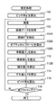
以下、図面を参照して、本発明を実施するための形態例について詳細に説明する。 Embodiments for carrying out the present invention will be described below in detail with reference to the drawings.
[第1の実施の形態]
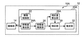
まず、図1を参照して、本実施の形態に係る推定装置10Aの構成について説明する。
[First Embodiment]
First, the configuration of
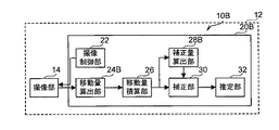
図1に示すように、本実施の形態に係る推定装置10Aは、車両12に各々設けられた撮像部14及びコンピュータ20Aを備えている。
As illustrated in FIG. 1, the
本実施の形態に係る撮像部14は、一例として、単眼の車載カメラであり、コンピュータ20Aによる制御によって、車両12の前方の画像を所定期間間隔(本実施の形態では、一例として33ミリ秒)で撮像し、撮像した画像を示す画像データをコンピュータ20Aに逐次出力する。なお、撮像部14は、カラー画像を撮像するものであってもよいし、モノクロ画像を撮像するものであってもよい。また、撮像部14は、動画撮像が可能なものであってもよいし、連写での静止画撮像が可能なものであってもよい。
The
本実施の形態に係るコンピュータ20Aは、CPUと、RAMと、後述する推定処理プログラムを記憶したROMと、不揮発性の記憶部とを備え、機能的には以下に示すように構成されている。コンピュータ20Aは、撮像制御部22、移動量算出部24A、移動量積算部26、補正量算出部28A、補正部30、及び推定部32を備えている。なお、撮像部14は、撮像手段の一例であり、移動量算出部24Aは、算出手段の一例である。また、移動量積算部26は、積算手段の一例であり、補正量算出部28A、及び補正部30は、補正手段の一例であり、推定部32は、推定手段の一例である。
The
本実施の形態に係る撮像制御部22は、撮像部14を制御して、車両12の前方の画像を上記所定期間間隔で撮像させる。
The
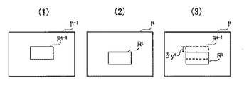
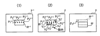
本実施の形態に係る移動量算出部24Aは、撮像部14により所定期間間隔で出力された画像データを逐次取得する。そして、移動量算出部24Aは、現時点の時刻tに取得した画像データと、現時点から上記所定期間間隔を1つ遡った時刻t−1に取得した画像データと、を用いて後述する移動量δytを算出する。以下、図2を参照して、移動量算出部24Aによる移動量δytを算出する処理について詳細に説明する。
The movement
図2(1)は、移動量算出部24Aにより時刻t−1に取得された画像データにより示される画像It−1を示し、図2(2)は、移動量算出部24Aにより時刻tに取得された画像データにより示される画像Itを示している。また、図2(3)は、画像It内の領域Rtの領域Rt−1に対する垂直方向(車両12のピッチング方向)の移動量δytを示している。
FIG. 2 (1) shows an image It -1 shown by the image data acquired at time t-1 by the movement
まず、図2(1)に示すように、移動量算出部24Aは、画像It−1を示す画像データから、画像It−1内の所定の位置を含む所定の大きさの矩形の領域Rt−1内の画像を示す画像データを抽出する。具体的には、本実施の形態に係る移動量算出部24Aは、一例として、全撮像領域の中央部を中心に含む図2(1)の縦方向及び横方向共に全撮像領域の3分の1の長さの矩形の領域Rt−1内の画像を示す画像データを抽出する。
First, as shown in FIG. 2 (1), the movement
次に、図2(2)に示すように、移動量算出部24Aは、パターンマッチングにより、画像It内の領域Rt−1に対応する領域Rtを探索する。具体的には、本実施の形態に係る移動量算出部24Aは、一例として、画像Itの図2(2)の左上端の位置から、領域Rt−1と同じ形状及び大きさの領域の位置を所定の画素数(本実施の形態では、3画素)ずつ右方向に右端までずらしながら、該領域内の画像を示す画像データと、領域Rt−1内の画像を示す画像データとの相関性を示す度合を算出する。また、移動量算出部24Aは、該算出する処理を、所定の画素数(本実施の形態では、2画素)ずつ図2(2)の下方向に、画像Itの下端まで繰り返し行う。
Next, as shown in FIG. 2 (2), the movement
そして、移動量算出部24Aは、上記相関性を示す度合が最も高い領域を領域Rtと決定する。なお、本実施の形態では、上記相関性を示す度合が最も高い領域として、対応する画素同士の画素値の差分における絶対値の全画素分の和が最小になる領域を適用しているが、これに限定されない。例えば、上記相関性を示す度合が最も高い領域として、2画素×2画素等、対応する複数の画素群毎の所定の位置の画素同士の画素値の差分における絶対値の全画素分の和が最小になる領域を適用してもよい。
The movement
そして、図2(3)に示すように、移動量算出部24Aは、移動量δytとして、領域Rt−1と領域Rtとの対応する位置(図2(3)では左上端部の位置)を示す画素位置間の垂直方向(図2(3)の上下方向)の画素数を算出する。
Then, as shown in FIG. 2 (3), the movement
このように、本実施の形態に係る移動量算出部24Aは、上記相関性を示す度合が最も高い画像It内の領域を領域Rtと決定しているが、これに限定されない。例えば、移動量算出部24Aは、画像It内の領域のうち、上記相関性を示す度合が予め定められた閾値以上の何れかの領域を領域Rtと決定してもよい。
Thus, the movement
この場合、例えば、移動量算出部24Aは、上記探索を開始して、最初に上記相関性を示す度合が上記閾値以上となった領域を領域Rtと決定する形態が例示される。これにより、移動量算出部24Aによる領域Rtの探索精度は低下する可能性はあるものの、移動量算出部24Aにより画像Itの全範囲に対して上記探索する処理を行わなくてもよくなるため、移動量算出部24Aによる演算量は低減する。
In this case, for example, the movement
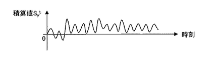
本実施の形態に係る移動量積算部26は、次の式(1)を用いて、時刻tにおける移動量δytの積算値Sy tとして、移動量算出部24Aにより逐次算出された移動量δytの積算値を算出する。
The movement

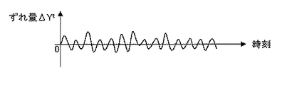
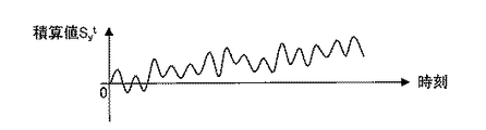
図3には、移動量積算部26により算出された積算値Sy tの時系列データの一例が示されている。なお、図3の縦軸は積算値Sy tを示し、横軸は時刻を示している。図3に示すように、積算値Sy tは時間の経過と共に、オフセットされた値となる。
FIG. 3 shows an example of time-series data of the integrated value S y t calculated by the movement
これは、前述したように、移動量積算部26が、移動量算出部24Aにより逐次算出された移動量δytを積算していることによって、移動量δytに含まれる誤差も積算されるためである。なお、この誤差は、例えば、移動量算出部24Aによる前述した領域Rtを探索する際の画像処理による影響、及び領域Rt−1内で撮像された被写体自体が時刻t−1から時刻tまでの間に動くことによる影響等によるものである。
As described above, this is because the movement
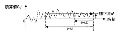
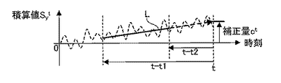
そこで、本実施の形態に係る補正量算出部28Aは、過去の所定期間内における移動量積算部26により算出された移動量δytの積算値Sy tの時系列データに基づいて、上記誤差を補正するための補正量ctを算出する。以下、図4を参照して、補正量算出部28Aによる補正量ctの算出処理について詳細に説明する。なお、図4には、図3に示した積算値Sy tの時系列データが破線で示されている。また、図3と同様に、図4の縦軸は積算値Sy tを示し、横軸は時刻を示している。
Therefore, the correction
図4に示すように、本実施の形態に係る補正量算出部28Aは、次の式(2)を用いて、時刻tにおける補正量ctとして、過去の所定期間(図4の時刻t−t1から時刻t−t2までの期間)の上記所定期間間隔毎の各時刻に算出された積算値Sy tの平均値を算出する。
As shown in FIG. 4, the correction
なお、本実施の形態では、上記過去の所定期間として、車両12の実機を用いた実験や車両12の設計仕様に基づくコンピュータ・シミュレーション等により、後述する車両12のピッチ角の推定精度が許容範囲内となる期間を固定的に適用しているが、これに限定されない。前述したように、上記誤差も積算されるため、上記所定期間として、補正量ctを算出する時点が遅くなるほど長い期間を適用してもよい。
In the present embodiment, the pitch angle estimation accuracy of the
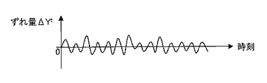
本実施の形態に係る補正部30は、補正量算出部28Aにより算出された補正量ctを用いて、移動量積算部26により算出された積算値Sy tを補正する。具体的には、補正部30は、次の式(3)を用いて、積算値Sy tから補正量ctを減算することにより、定常状態における画像内の水平線の垂直方向の位置に対する現時点の時刻tにおける画像内の水平線の垂直方向の位置のずれ量ΔYtを算出する。なお、ここでいう定常状態としては、例えば、車両12が停止している状態や前述した移動量δyt≒0の状態が長期間継続している状態等の車両12の垂直方向に対するゆれがほぼ無い状態が挙げられる。
Correcting
図5には、図3に示した積算値Sy tの時系列データを、上記所定期間間隔毎の各時刻において補正部30により補正して得られたずれ量ΔYtの時系列データが示されている。なお、図5の縦軸はずれ量ΔYtを示し、横軸は時刻を示している。
FIG. 5 shows time series data of the deviation amount ΔY t obtained by correcting the time series data of the integrated value S y t shown in FIG. 3 by the
ここで、ずれ量ΔYtについて詳細に説明する。時刻tにおける撮像部14により撮像された画像における水平線の垂直方向の位置Ytは、次の式(4)で表される。
そして、一般的に、時刻tにおける位置Ytは、定常状態における位置Y0を中心として変動するため、時刻tまでの各時刻に算出されたずれ量△Ytの平均値は、ほぼ0(零)に等しくなる。また、積算値Sy tは、移動量δytに上記誤差が含まれない場合は、ずれ量△Ytに等しくなる。すなわち、この場合は、積算値Sy tの平均値も、ほぼ0(零)に等しくなる。 In general, the position Y t at the time t fluctuates around the position Y 0 in the steady state. Therefore , the average value of the deviation amounts ΔY t calculated at each time up to the time t is almost 0 ( Equal to zero). Further, the integrated value S y t, if not included the error in the amount of movement .delta.y t is is equal to the deviation amount △ Y t. In other words, in this case, the average value of the integrated values S y t is also substantially equal to 0 (zero).
しかしながら、前述したように、積算値Sy tには移動量δytの上記誤差が含まれる。そこで、本実施の形態では、前述したように、上記誤差の補正に用いる補正量ctとして、上記所定期間の上記所定期間間隔毎の各時刻に算出された積算値Sy tの平均値を算出している。 However, as described above, the integrated value S y t includes the error of the movement amount δy t . Therefore, in this embodiment, as described above, as the correction amount c t used for correction of the error, the mean value of the integrated value S y t calculated for each time point for each said predetermined period intervals of the predetermined time period Calculated.
本実施の形態に係る推定部32は、補正部30により補正された積算値Sy t(=ずれ量△Yt)に基づいて、車両12のピッチ角を推定する。具体的には、推定部32は、撮像部14の解像度及び焦点距離等の諸元値を用いて、ずれ量△Ytから撮像部14のピッチ角φtを算出する。
The
このピッチ角φtは、定常状態の撮像部14の光軸に対する時刻tにおける撮像部14の光軸の角度であるため、推定部32は、定常状態における撮像部14の路面に対する撮像部14の光軸のピッチ角φ0を算出する。そして、推定部32は、時刻tにおける車両12のピッチ角として、撮像部14の光軸の路面に対する角度であるピッチ角φ0とピッチ角φtとを加算した角度を算出する。
Since the pitch angle φ t is the angle of the optical axis of the
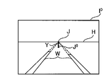
ここで、図6を参照して、上記定常状態におけるピッチ角φ0の算出処理について説明する。ここでは、錯綜を回避するために、一例として、撮像部14が、光軸の路面に対するピッチ角が0度の場合に、光軸が画像の中心に位置する撮像手段であるものとして説明する。なお、図6は、上記定常状態において撮像部14により撮像された画像I0の一例を示している。
Here, with reference to FIG. 6, the calculation process of the pitch angle φ 0 in the steady state will be described. Here, in order to avoid complications, as an example, it is assumed that the
図6に示すように、推定部32は、2本の白線Wの交点Jを、水平線Hの垂直方向の位置と見なして、定常状態における水平線の位置のずれ量Yとして、交点Jと、車両のピッチ角が0度である場合に対して予め求められた画像I0の交点J0との画素位置間の垂直方向(図6の上下方向)の画素数を算出する。そして、推定部32は、撮像部14の解像度及び焦点距離等の諸元値を用いて、ずれ量Yからピッチ角φ0を算出する。なお、定常状態におけるピッチ角φ0の算出処理は、これに限定されず、他の公知の手法を用いてもよい。
As shown in FIG. 6, the
次に、図7を参照して、本実施の形態に係る推定装置10Aの作用について説明する。なお、図7は、例えば車両12のイグニッションスイッチがオン状態とされた際にコンピュータ20AのCPUによって実行される推定処理プログラムの処理の流れを示すフローチャートである。
Next, with reference to FIG. 7, the operation of
図7のステップ100において、推定部32は、前述したように、撮像部14を制御して、車両12の前方の画像を撮像させ、該撮像により得られた画像I0から定常状態におけるピッチ角φ0を算出する。
In
次のステップ101において、撮像制御部22は、撮像部14を制御して、車両12の前方の画像を撮像させる。次のステップ102において、移動量算出部24Aは、上記ステップ101の処理により撮像部14から出力された画像Itを示す画像データを取得する。
In the
次のステップ104Aにおいて、移動量算出部24Aは、上記ステップ101〜後述するステップ118の繰り返し処理における前回の上記ステップ102の処理により取得された画像データから、該画像データにより示される画像It−1の領域Rt−1内の画像を示す画像データを抽出する。なお、本ステップ104Aの処理及び後述するステップ106A〜ステップ116の処理は、本推定処理プログラムの実行を開始してから初回に実行されたタイミングでは実行されない。
In the
次のステップ106Aにおいて、移動量算出部24Aは、前述したように、直前の上記ステップ102の処理により取得された画像データにより示される画像Itにおける上記ステップ104Aの処理により抽出された領域Rt−1に対応する領域Rtを探索する。
In the
次のステップ108Aにおいて、移動量算出部24Aは、前述したように、上記ステップ104Aの処理により抽出された領域Rt−1と、上記ステップ106Aの処理により探索された領域Rtとの対応する画素位置に基づいて、移動量δytを算出する。
In the next step 108A, the shift
次のステップ110において、移動量積算部26は、前述したように、上記式(1)を用いて、上記ステップ108Aの処理により算出された移動量δytの積算値Sy tを算出する。
In the
次のステップ112Aにおいて、補正量算出部28Aは、上記式(2)を用いて、補正量ctとして、上記過去の所定期間に上記ステップ110の処理により算出された積算値Sy tの平均値を算出する。
In the
次のステップ114において、補正部30は、上記式(3)を用いて、上記ステップ110の処理により算出された積算値Sy tから上記ステップ112Aの処理により算出された補正量ctを減算することにより、ずれ量ΔYtを算出する。
In the
次のステップ116において、推定部32は、前述したように、撮像部14の諸元値を用いて、上記ステップ114の処理により算出されたずれ量ΔYtからピッチ角φtを算出する。そして、推定部32は、前述したように、該ピッチ角φtと上記ステップ100の処理により算出されたピッチ角φ0とを加算して、車両12のピッチ角を算出する。なお、ここで算出したピッチ角は、例えば、車両12の高度運転支援等で、カメラ等の撮像手段により撮像された車両12の前方の画像内のある物体への距離を推定する場合等の2次元の情報から3次元の情報を推定する場合に用いられる。
In the
ステップ118において、推定部32は、所定の終了タイミングが到来したか否かを判定する。この判定が否定判定となった場合は上記ステップ101の処理に戻る一方、肯定判定となった場合は本推定処理プログラムを終了する。なお、本実施の形態では、上記所定の終了タイミングとして、一例として車両12のイグニッションスイッチがオフ状態とされたタイミングを適用している。
In
なお、前述したように、例えば、上記ステップ108Aの処理により算出された移動量δytが長期間ほぼ0(零)である状態(すなわち、定常状態)が継続した場合は、積算値Sy tを0(零)にリセットして、ステップ100の処理から本推定処理プログラムを再度実行してもよい。
As described above, for example, when the movement amount δy t calculated by the process of step 108A continues to be approximately 0 (zero) for a long time (that is, the steady state), the integrated value S y t May be reset to 0 (zero), and the estimation processing program may be executed again from the processing of
以上説明したように、本実施の形態によれば、過去の所定期間内における積算値Sy tの時系列データに基づいて、現時点の積算値Sy tを補正しているので、車両12の速度が比較的低い場合であっても、単眼の撮像部14を用いて、車両12のピッチ角を精度良く推定することができる。また、本実施の形態によれば、上記並進ベクトル及び回転行列を算出する場合に比較して、少ない演算量で車両12のピッチ角を精度良く推定することができる。
As described above, according to the present embodiment, the current integrated value S y t is corrected based on the time-series data of the integrated value S y t within a predetermined period in the past. Even when the speed is relatively low, the pitch angle of the
[第2の実施の形態]
まず、図8を参照して、本実施の形態に係る推定装置10Bの構成について説明する。なお、図8における図1と同一の機能を有する構成要素については、図1と同一の符号を付して、その説明を省略する。
[Second Embodiment]
First, the configuration of estimation apparatus 10B according to the present embodiment will be described with reference to FIG. In FIG. 8, components having the same functions as those in FIG. 1 are denoted by the same reference numerals as those in FIG. 1, and description thereof is omitted.
図8に示すように、本実施の形態に係る推定装置10Bは、コンピュータ20Aに代えてコンピュータ20Bを備えている点が上記第1の実施の形態に係る推定装置10Aとは異なっている。また、本実施の形態に係るコンピュータ20Bは、移動量算出部24Aに代えて移動量算出部24Bを備えている点、及び補正量算出部28Aに代えて補正量算出部28Bを備えている点が上記第1の実施の形態に係るコンピュータ20Aとは異なっている。
As shown in FIG. 8, the estimation apparatus 10B according to the present embodiment is different from the
本実施の形態に係る移動量算出部24Bは、撮像部14により所定期間間隔で出力された画像データを逐次取得する。そして、現時点の時刻tに取得した画像データと、現時点から上記所定期間間隔を1つ遡った時刻t−1に取得した画像データと、を用いて移動量δytを算出する。以下、図9を参照して、移動量算出部24Bによる移動量δytを算出する処理について詳細に説明する。
The movement
図9(1)は、移動量算出部24Bにより時刻t−1に取得された画像データにより示される画像It−1、及び後述するオプティカルフローVi tの算出に用いる点(以下、「算出点」という。)Pi t−1((i=1...N(Nは自然数。本実施の形態では、5)))を示している。また、図9(2)は、移動量算出部24Bにより時刻tに取得された画像データにより示される画像It、及び後述するオプティカルフローVi tを示している。また、図9(3)は、図2(3)と同様に、移動量δytを示している。
9 (1), the point used for calculating the image I t-1, and described below optical flow V i t indicated by the image data acquired at time t-1 by the movement
まず、図9(1)に示すように、移動量算出部24Bは、画像It−1を示す画像データから、画像It−1内の上記所定の大きさの矩形の領域Rt−1内の画像を示す画像データを抽出する。なお、本実施の形態では、領域Rt−1として、車両12のピッチングが発生していない状態で車両12が進行した場合に、遠近法における消失点を含む領域を適用している。これは、該領域が、車両12の進行の影響による動きが比較的少ない領域と見なせる領域であるためである。
First, as shown in FIG. 9 (1), the movement
次に、図9(1)に示すように、移動量算出部24Bは、領域Rt−1内のN個の予め定められた位置を算出点Pi t−1の位置と決定する。なお、本実施の形態では、一例として、算出点Pi t−1の位置として、垂直方向(図9(1)の縦方向)に対しては領域Rt−1の中央の位置で、水平方向(図9(1)の横方向)に対しては各々互いに同一の間隔を隔てた位置を適用している。このように、本実施の形態では、算出点Pi t−1の位置として、予め固定的に定められた位置を適用しているが、これに限定されない。例えば、算出点Pi t−1の位置として、Harris operator(「C.Harris and M.Stephens(1988).“A combined corner and edge detector”.“Proceedings of the 4th Alvey Vision Conference”. pp.147-151」参照。)等を用いて、複数の画像間の対応する点の対応が取りやすい位置を適用してもよい。
Next, as illustrated in FIG. 9A, the movement
また、図9(2)に示すように、移動量算出部24Bは、各算出点Pi t−1について、時刻tにおけるオプティカルフローVi t(={vxi t、vyi t})を各々算出する。ここで、上記vxi tはオプティカルフローVi tのx成分(水平方向の成分)を表し、上記vyi tはオプティカルフローVi tのy成分(垂直方向の成分)を表す。なお、本実施の形態では、オプティカルフローVi tの算出に用いる手法として、ブロックマッチング法を適用しているが、これに限定されない。例えば、該手法として、lucas-kanade法等の他の手法を適用してもよい。
Also, as shown in FIG. 9 (2), the movement
また、移動量算出部24Bは、移動量δytとして、オプティカルフローVi tのy成分(vyi t)の平均値を算出する。なお、本実施の形態に係る移動量算出部24Bは、該平均値を算出する際に、オプティカルフローVi tのy成分の値が正常値である範囲として予め定められた範囲外であるオプティカルフローVi t(図9(2)に示すV4 t)については算入しない。具体的には、例えば、移動量算出部24Bは、上記平均値を算出する際に、他のオプティカルフローVi tのy成分の値の平均値との差が、所定の範囲(例えば、該平均値の±50%の範囲)外であるオプティカルフローVi tについては算入しない。
Further, the movement
このように、本実施の形態では、移動量δytとして、オプティカルフローVi tのy成分の値の平均値を適用しているが、これに限定されない。例えば、移動量δytとして、オプティカルフローVi tのy成分の値の中央値を適用してもよい。 As described above, in this embodiment, the average value of the y component values of the optical flow V i t is applied as the movement amount δy t , but is not limited to this. For example, the median value of the y component values of the optical flow V i t may be applied as the movement amount δy t .
本実施の形態に係る補正量算出部28Bは、過去の所定期間内における移動量積算部26により算出された移動量δytの積算値Sy tの時系列データに基づいて、補正量ctを算出する。以下、図10及び図11を参照して、補正量算出部28Bによる補正量ctの算出処理について詳細に説明する。なお、図10には、図3と同様に、積算値Sy tの時系列データが示されている。また、図11には、図4と同様に、図10に示した積算値Sy tの時系列データが破線で示されている。
The correction amount calculation unit 28B according to the present embodiment uses the correction amount c t based on the time series data of the integrated value S y t of the movement amount δy t calculated by the movement
上記第1の実施の形態で前述した移動量δytに含まれる誤差は、一定の値であるとは限らない。そこで、本実施の形態では、図11に示すように、補正量算出部28Bは、過去の所定期間(図11の時刻t−t1から時刻t−t2までの期間)の上記所定期間間隔毎の各時刻に算出された積算値Sy tを、例えば最小二乗法等を用いて近似することにより、回帰直線Lを示す一次式を示す一次係数及び定数を算出する。そして、補正量算出部28Bは、該一次式を用いた外挿により、時刻tにおける補正量ctを算出する。なお、図12には、図5と同様に、図11に示した積算値Sy tの時系列データを、上記所定期間間隔毎の各時刻において補正部30により補正したずれ量ΔYtの時系列データが示されている。
The error included in the movement amount δy t described in the first embodiment is not necessarily a constant value. Therefore, in the present embodiment, as shown in FIG. 11, the correction amount calculation unit 28 </ b> B performs the past predetermined period (period from time t-t1 to time t-t2 in FIG. 11) for each predetermined period. By approximating the integrated value S y t calculated at each time using, for example, the least square method or the like, a linear coefficient and a constant indicating a linear expression representing the regression line L are calculated. Then, the correction amount calculating section 28B is by extrapolation using the linear expression to calculate the correction amount c t at time t. Incidentally, in FIG. 12, like FIG. 5, the time-series data of integrated value S y t shown in FIG. 11, when the shift amount [Delta] Y t corrected by the
このように、本実施の形態では、積算値Sy tの時系列データを一次式に近似しているが、これに限定されない。例えば、積算値Sy tの時系列データを二次式等に近似してもよいし、過去の所定期間の積算値Sy tの時系列データから時刻tの補正量ctを外挿により算出可能であれば、近似する手法は限定されない。 As described above, in the present embodiment, the time series data of the integrated value S y t is approximated to a linear expression, but the present invention is not limited to this. For example, time-series data of integrated value S y t may be approximated to the quadratic equation, etc., by extrapolation the correction amount c t integrated value S y time t from the time series data of t in the past predetermined period As long as calculation is possible, the approximation method is not limited.
次に、図13を参照して、本実施の形態に係る推定装置10Bの作用について説明する。なお、図13は、例えば車両12のイグニッションスイッチがオン状態とされた際にコンピュータ20BのCPUによって実行される推定処理プログラムの処理の流れを示すフローチャートである。また、図13における図7と同一の処理を実行するステップについては図7と同一のステップ番号を付して、その説明を省略する。
Next, with reference to FIG. 13, the effect | action of the estimation apparatus 10B which concerns on this Embodiment is demonstrated. FIG. 13 is a flowchart showing the flow of processing of the estimation processing program executed by the CPU of the
図13のステップ104Bにおいて、移動量算出部24Bは、上記繰り返し処理における前回のステップ102の処理により取得された画像データから、該画像データにより示される画像It−1の領域Rt−1内の画像を示す画像データを抽出する。
In step 104B of FIG. 13, the movement
次のステップ106Bにおいて、移動量算出部24Bは、前述したように、上記ステップ104Bの処理により抽出された画像データにより示される領域Rt−1内のN個の上記予め定められた位置を算出点Pi t−1の位置と決定する。そして、移動量算出部24Bは、前述したように、上記ステップ104Bの処理により抽出された画像データ、及び直前の上記ステップ102の処理により取得された画像データを用いて、各算出点Pi t−1について、オプティカルフローVi tを算出する。
In the
次のステップ108Bにおいて、移動量算出部24Bは、前述したように、移動量δytとして、上記ステップ106Bの処理により算出された各算出点Pi t−1のオプティカルフローVi tのy成分の平均値を算出する。
In the
その後、ステップ112Bにおいて、補正量算出部28Bは、前述したように、過去の所定期間内における移動量算出部24Bにより算出された移動量δytの積算値Sy tの時系列データに基づいて、補正量ctを算出する。
Thereafter, in
以上説明したように、本実施の形態によれば、上記第1の実施の形態と同様の効果を奏することができる。 As described above, according to the present embodiment, the same effects as those of the first embodiment can be obtained.
なお、上記第1の実施の形態において、上記第2の実施の形態のように、領域Rt−1として、上記消失点を含む領域を適用してもよい。また、上記第1の実施の形態において、上記第2の実施の形態のように、オプティカルフローVi tを用いて移動量δytを算出してもよい。また、上記第1の実施の形態において、上記第2の実施の形態のように、過去の所定期間内の積算値Sy tの時系列データを近似して、外挿により補正量ctを算出してもよい。また、上記第2の実施の形態においても、移動量δytが長期間ほぼ0(零)である状態が継続した場合は、積算値Sy tを0(零)にリセットして、再度ステップ100の処理から推定処理プログラムを再度実行してもよい。 In the first embodiment, a region including the vanishing point may be applied as the region R t-1 as in the second embodiment. Further, in the above first embodiment, as hereinabove described second embodiment, may be calculated movement amount .delta.y t using optical flow V i t. Further, in the above first embodiment, as hereinabove described second embodiment, by approximating the time-series data of integrated value S y t within a past predetermined period, the correction amount c t by extrapolation It may be calculated. Also in the second embodiment, if the movement amount δy t continues to be approximately 0 (zero) for a long time, the integrated value S y t is reset to 0 (zero) and the step is performed again. The estimation processing program may be executed again from 100 processes.
また、上記各実施の形態では、撮像部14により車両12の前方の画像を撮像する場合について説明したが、本発明はこれに限定されるものではない。例えば、撮像部14により車両12の後方の画像を撮像する形態としてもよい。この場合、例えば、上記各実施の形態と同様に車両12のピッチ角を算出し、該ピッチ角の正負の符号を反転させた角度を車両12のピッチ角と推定する形態が例示される。
Moreover, although each said embodiment demonstrated the case where the image ahead part of the
また、上記各実施の形態と撮像部14により車両12の後方の画像を撮像する上記形態例とを組み合わせても良い。この場合、上記誤差を補正するための補正量ctの絶対値が小さいほど、該誤差が小さいと考えられる。そこで、この場合、例えば、車両12の前方と後方とを各々撮像して得られた画像の各々を用いて算出された補正量ctのうち、絶対値が小さい方の補正量ctを用いて車両12のピッチ角を算出する形態が例示される。また、例えば、車両12のピッチ角として、車両12の前方と後方とを各々撮像して得られた画像の各々を用いて算出されたピッチ角の平均値を算出する形態も例示される。
Moreover, you may combine said each embodiment and the said form example which images the image of the back of the
また、上記各実施の形態では、領域Rの形状として、矩形を適用した場合について説明したが、本発明はこれに限定されるものではない。例えば、撮像部14による撮像により得られた画像から、移動量δytを算出可能な形状であれば、円形、三角形等の他の形状でもよいことは言うまでもない。
In each of the above embodiments, the case where a rectangle is applied as the shape of the region R has been described. However, the present invention is not limited to this. For example, it is needless to say that other shapes such as a circle and a triangle may be used as long as the movement amount δy t can be calculated from an image obtained by imaging by the
10A、10B 推定装置
12 車両
14 撮像部
20A、20B コンピュータ
22 撮像制御部
24A、24B 移動量算出部
26 移動量積算部
28A、28B 補正量算出部
30 補正部
32 推定部
10A,
Claims (8)
第1時刻に前記撮像手段により撮像された画像内の所定領域の位置、及び前記第1時刻より後の第2時刻に前記撮像手段により同一方向に対して撮像された画像内の前記所定領域に対応する領域の位置に基づいて、前記所定領域の垂直方向の移動量を算出する算出手段と、
前記算出手段により前記移動量が算出される毎に、該移動量の積算値を算出する積算手段と、
過去の所定期間内における前記積算手段により算出された前記移動量の積算値の時系列データに基づいて、前記積算手段により算出された現時点の前記積算値を補正する補正手段と、
前記補正手段により補正された前記積算値に基づいて、前記車両のピッチ角を推定する推定手段と、
を含む推定装置。 An imaging means provided in the vehicle for capturing at least one of the front and rear images of the vehicle;
The position of the predetermined area in the image captured by the imaging means at the first time and the predetermined area in the image captured in the same direction by the imaging means at the second time after the first time. Calculation means for calculating a vertical movement amount of the predetermined area based on the position of the corresponding area;
An integration unit that calculates an integrated value of the movement amount each time the movement amount is calculated by the calculation unit;
Correction means for correcting the current integrated value calculated by the integrating means based on time-series data of the integrated value of the movement amount calculated by the integrating means in a past predetermined period;
Estimating means for estimating a pitch angle of the vehicle based on the integrated value corrected by the correcting means;
Including the estimation device.
請求項1記載の推定装置。 The estimation device according to claim 1, wherein the correction unit corrects the current integrated value using an average value of time-series data of the integrated value of the movement amount as a correction amount.
請求項1記載の推定装置。 The correction means calculates an extrapolated value obtained by approximating time series data of the integrated value of the movement amount as a correction amount, and corrects the current integrated value using the correction amount. Estimating device.
請求項1から請求項3の何れか1項記載の推定装置。 The correction means, based on the time series data of the integrated value of the movement amount and the current integrated value calculated by the integrating means, as the vertical deviation amount of the image from the steady state at the current time, The estimation apparatus according to any one of claims 1 to 3, wherein the corrected integrated value at the present time is calculated.
請求項1から請求項4の何れか1項記載の推定装置。 The estimation device according to claim 1, wherein the predetermined region is a region including a vanishing point in perspective.
請求項1から請求項5の何れか1項記載の推定装置。 The estimation device according to any one of claims 1 to 5, wherein the correction unit corrects the current integrated value by setting the predetermined period to be a longer period as the correction time becomes later.
請求項1から請求項6の何れか1項記載の推定装置。 The calculation unit calculates the movement amount after searching the predetermined area at the second time corresponding to the predetermined area at the first time by pattern matching. The estimation device described.
車両に設けられ、該車両の前方及び後方の少なくとも一方の画像を撮像する撮像手段により第1時刻に撮像された画像内の所定領域の位置、及び前記第1時刻より後の第2時刻に前記撮像手段により同一方向に対して撮像された画像内の前記所定領域に対応する領域の位置に基づいて、前記所定領域の垂直方向の移動量を算出する算出手段と、
前記算出手段により前記移動量が算出される毎に、該移動量の積算値を算出する積算手段と、
過去の所定期間内における前記積算手段により算出された前記移動量の積算値の時系列データに基づいて、前記積算手段により算出された現時点の前記積算値を補正する補正手段と、
前記補正手段により補正された前記積算値に基づいて、前記車両のピッチ角を推定する推定手段と、
として機能させるための推定プログラム。 Computer
A position of a predetermined region in an image captured at a first time by an imaging means provided on the vehicle and capturing at least one of the front and rear images of the vehicle; and the second time after the first time Calculation means for calculating a vertical movement amount of the predetermined area based on a position of an area corresponding to the predetermined area in an image imaged in the same direction by the imaging means;
An integration unit that calculates an integrated value of the movement amount each time the movement amount is calculated by the calculation unit;
Correction means for correcting the current integrated value calculated by the integrating means based on time-series data of the integrated value of the movement amount calculated by the integrating means in a past predetermined period;
Estimating means for estimating a pitch angle of the vehicle based on the integrated value corrected by the correcting means;
Estimating program to function as.
Priority Applications (3)
| Application Number | Priority Date | Filing Date | Title |
|---|---|---|---|
| JP2015139792A JP6184447B2 (en) | 2015-07-13 | 2015-07-13 | Estimation apparatus and estimation program |
| PCT/JP2016/068920 WO2017010268A1 (en) | 2015-07-13 | 2016-06-24 | Estimation device and estimation program |
| US15/735,357 US10422634B2 (en) | 2015-07-13 | 2016-06-24 | Estimating device and estimating program |
Applications Claiming Priority (1)
| Application Number | Priority Date | Filing Date | Title |
|---|---|---|---|
| JP2015139792A JP6184447B2 (en) | 2015-07-13 | 2015-07-13 | Estimation apparatus and estimation program |
Publications (2)
| Publication Number | Publication Date |
|---|---|
| JP2017020942A JP2017020942A (en) | 2017-01-26 |
| JP6184447B2 true JP6184447B2 (en) | 2017-08-23 |
Family
ID=57756914
Family Applications (1)
| Application Number | Title | Priority Date | Filing Date |
|---|---|---|---|
| JP2015139792A Expired - Fee Related JP6184447B2 (en) | 2015-07-13 | 2015-07-13 | Estimation apparatus and estimation program |
Country Status (3)
| Country | Link |
|---|---|
| US (1) | US10422634B2 (en) |
| JP (1) | JP6184447B2 (en) |
| WO (1) | WO2017010268A1 (en) |
Families Citing this family (3)
| Publication number | Priority date | Publication date | Assignee | Title |
|---|---|---|---|---|
| JP6601352B2 (en) * | 2016-09-15 | 2019-11-06 | 株式会社デンソー | Vehicle posture estimation device |
| JP2019007739A (en) * | 2017-06-20 | 2019-01-17 | 日産自動車株式会社 | Self position estimation method and self position estimation device |
| WO2019216393A1 (en) * | 2018-05-10 | 2019-11-14 | パナソニックIpマネジメント株式会社 | Road surface state estimating method, road surface state estimating device, and road surface state estimating system |
Family Cites Families (8)
| Publication number | Priority date | Publication date | Assignee | Title |
|---|---|---|---|---|
| US5638116A (en) * | 1993-09-08 | 1997-06-10 | Sumitomo Electric Industries, Ltd. | Object recognition apparatus and method |
| JP4586571B2 (en) | 2005-02-25 | 2010-11-24 | 株式会社豊田中央研究所 | Object judgment device |
| JP2006012191A (en) * | 2005-09-01 | 2006-01-12 | Honda Motor Co Ltd | Lane marking recognition device for vehicle |
| US8164628B2 (en) * | 2006-01-04 | 2012-04-24 | Mobileye Technologies Ltd. | Estimating distance to an object using a sequence of images recorded by a monocular camera |
| CA2678156C (en) * | 2007-02-16 | 2013-10-08 | Mitsubishi Electric Corporation | Measurement apparatus, measurement method, and feature identification apparatus |
| JP5570902B2 (en) * | 2010-07-28 | 2014-08-13 | 本田技研工業株式会社 | Vehicle pitch angle estimation device |
| JP6011489B2 (en) * | 2013-08-26 | 2016-10-19 | トヨタ自動車株式会社 | In-vehicle control device |
| CN111380545A (en) * | 2015-02-10 | 2020-07-07 | 御眼视觉技术有限公司 | Method, server, autonomous vehicle, and medium for autonomous vehicle navigation |
-
2015
- 2015-07-13 JP JP2015139792A patent/JP6184447B2/en not_active Expired - Fee Related
-
2016
- 2016-06-24 WO PCT/JP2016/068920 patent/WO2017010268A1/en active Application Filing
- 2016-06-24 US US15/735,357 patent/US10422634B2/en active Active
Also Published As
| Publication number | Publication date |
|---|---|
| WO2017010268A1 (en) | 2017-01-19 |
| JP2017020942A (en) | 2017-01-26 |
| US10422634B2 (en) | 2019-09-24 |
| US20180180409A1 (en) | 2018-06-28 |
Similar Documents
| Publication | Publication Date | Title |
|---|---|---|
| CN106981074B (en) | Method and apparatus for estimating an orientation of a camera relative to a surface | |
| US10762643B2 (en) | Method for evaluating image data of a vehicle camera | |
| JP6211263B2 (en) | Road vertical contour detection | |
| US8102427B2 (en) | Camera egomotion estimation from an infra-red image sequence for night vision | |
| JP3868876B2 (en) | Obstacle detection apparatus and method | |
| US20160182793A1 (en) | Image distortion correction of a camera with a rolling shutter | |
| WO2015125298A1 (en) | Local location computation device and local location computation method | |
| JP6112221B2 (en) | Moving object position estimation apparatus and moving object position estimation method | |
| WO2015198930A1 (en) | Distance measurement device, and distance measurement correction device using correction parameter | |
| JP2019510312A (en) | Method, computer device, driver assistance system, and motor vehicle for motion estimation between two images of an environmental region of a motor vehicle | |
| US20090295922A1 (en) | In-vehicle device | |
| US10187630B2 (en) | Egomotion estimation system and method | |
| WO2015125299A1 (en) | Local location computation device and local location computation method | |
| US10991105B2 (en) | Image processing device | |
| JP6184447B2 (en) | Estimation apparatus and estimation program | |
| WO2019156072A1 (en) | Attitude estimating device | |
| JP2017517727A (en) | Scale measurement of 3D information | |
| JP5304064B2 (en) | Speed measuring device and speed measuring method | |
| JP6488226B2 (en) | Runway parameter estimation apparatus and program | |
| JP7303064B2 (en) | Image processing device and image processing method | |
| CN111260538B (en) | Positioning and vehicle-mounted terminal based on long-baseline binocular fisheye camera | |
| JP7247772B2 (en) | Information processing device and driving support system | |
| EP3435286B1 (en) | Imaging control device and imaging control method | |
| US10726528B2 (en) | Image processing apparatus and image processing method for image picked up by two cameras | |
| CN110570680A (en) | Method and system for determining position of object using map information |
Legal Events
| Date | Code | Title | Description |
|---|---|---|---|
| TRDD | Decision of grant or rejection written | ||
| A01 | Written decision to grant a patent or to grant a registration (utility model) |
Free format text: JAPANESE INTERMEDIATE CODE: A01 Effective date: 20170704 |
|
| A61 | First payment of annual fees (during grant procedure) |
Free format text: JAPANESE INTERMEDIATE CODE: A61 Effective date: 20170725 |
|
| R150 | Certificate of patent or registration of utility model |
Ref document number: 6184447 Country of ref document: JP Free format text: JAPANESE INTERMEDIATE CODE: R150 |
|
| R250 | Receipt of annual fees |
Free format text: JAPANESE INTERMEDIATE CODE: R250 |
|
| R250 | Receipt of annual fees |
Free format text: JAPANESE INTERMEDIATE CODE: R250 |
|
| R250 | Receipt of annual fees |
Free format text: JAPANESE INTERMEDIATE CODE: R250 |
|
| LAPS | Cancellation because of no payment of annual fees |