WO2018047847A1 - 運動解析装置、運動解析方法及び運動解析プログラム - Google Patents
運動解析装置、運動解析方法及び運動解析プログラム Download PDFInfo
- Publication number
- WO2018047847A1 WO2018047847A1 PCT/JP2017/032049 JP2017032049W WO2018047847A1 WO 2018047847 A1 WO2018047847 A1 WO 2018047847A1 JP 2017032049 W JP2017032049 W JP 2017032049W WO 2018047847 A1 WO2018047847 A1 WO 2018047847A1
- Authority
- WO
- WIPO (PCT)
- Prior art keywords
- muscle
- myoelectric potential
- motion
- equilibrium point
- limb
- Prior art date
- Legal status (The legal status is an assumption and is not a legal conclusion. Google has not performed a legal analysis and makes no representation as to the accuracy of the status listed.)
- Ceased
Links
Images




Classifications
-
- A—HUMAN NECESSITIES
- A61—MEDICAL OR VETERINARY SCIENCE; HYGIENE
- A61B—DIAGNOSIS; SURGERY; IDENTIFICATION
- A61B5/00—Measuring for diagnostic purposes; Identification of persons
- A61B5/103—Measuring devices for testing the shape, pattern, colour, size or movement of the body or parts thereof, for diagnostic purposes
- A61B5/11—Measuring movement of the entire body or parts thereof, e.g. head or hand tremor or mobility of a limb
- A61B5/1126—Measuring movement of the entire body or parts thereof, e.g. head or hand tremor or mobility of a limb using a particular sensing technique
-
- A—HUMAN NECESSITIES
- A61—MEDICAL OR VETERINARY SCIENCE; HYGIENE
- A61B—DIAGNOSIS; SURGERY; IDENTIFICATION
- A61B5/00—Measuring for diagnostic purposes; Identification of persons
- A61B5/103—Measuring devices for testing the shape, pattern, colour, size or movement of the body or parts thereof, for diagnostic purposes
- A61B5/107—Measuring physical dimensions, e.g. size of the entire body or parts thereof
-
- A—HUMAN NECESSITIES
- A61—MEDICAL OR VETERINARY SCIENCE; HYGIENE
- A61B—DIAGNOSIS; SURGERY; IDENTIFICATION
- A61B5/00—Measuring for diagnostic purposes; Identification of persons
- A61B5/24—Detecting, measuring or recording bioelectric or biomagnetic signals of the body or parts thereof
- A61B5/316—Modalities, i.e. specific diagnostic methods
- A61B5/389—Electromyography [EMG]
-
- A—HUMAN NECESSITIES
- A61—MEDICAL OR VETERINARY SCIENCE; HYGIENE
- A61B—DIAGNOSIS; SURGERY; IDENTIFICATION
- A61B5/00—Measuring for diagnostic purposes; Identification of persons
- A61B5/68—Arrangements of detecting, measuring or recording means, e.g. sensors, in relation to patient
- A61B5/6801—Arrangements of detecting, measuring or recording means, e.g. sensors, in relation to patient specially adapted to be attached to or worn on the body surface
- A61B5/6813—Specially adapted to be attached to a specific body part
- A61B5/6824—Arm or wrist
-
- A—HUMAN NECESSITIES
- A61—MEDICAL OR VETERINARY SCIENCE; HYGIENE
- A61H—PHYSICAL THERAPY APPARATUS, e.g. DEVICES FOR LOCATING OR STIMULATING REFLEX POINTS IN THE BODY; ARTIFICIAL RESPIRATION; MASSAGE; BATHING DEVICES FOR SPECIAL THERAPEUTIC OR HYGIENIC PURPOSES OR SPECIFIC PARTS OF THE BODY
- A61H1/00—Apparatus for passive exercising; Vibrating apparatus; Chiropractic devices, e.g. body impacting devices, external devices for briefly extending or aligning unbroken bones
- A61H1/02—Stretching or bending or torsioning apparatus for exercising
-
- A—HUMAN NECESSITIES
- A63—SPORTS; GAMES; AMUSEMENTS
- A63B—APPARATUS FOR PHYSICAL TRAINING, GYMNASTICS, SWIMMING, CLIMBING, OR FENCING; BALL GAMES; TRAINING EQUIPMENT
- A63B69/00—Training appliances or apparatus for special sports
Definitions
- the present invention relates to a motion analysis technique for calculating a feature amount related to motion control of an operating point such as a proper body position, for example, the tip of a limb.
- Patent Document 1 A motion analysis method for visualizing a motion strategy (manipulation of encoded higher order variables such as equilibrium point trajectories) selected by the central nervous system has been proposed (Patent Document 1, Non-Patent Document 1).
- Patent Document 1 A motion analysis method for visualizing a motion strategy (manipulation of encoded higher order variables such as equilibrium point trajectories) selected by the central nervous system has been proposed (Patent Document 1, Non-Patent Document 1).
- the size and balance of muscles constituting the musculoskeletal model are equivalent, and (2) the moment arms of each joint such as the shoulder and elbow are equal.
- Patent Document 1 and Non-Patent Document 1 can explain the motion using a simplified model for a limited motion, but the general motion In some cases, this assumption is not always sufficient. In particular, the assumption (3) has a certain practical limit in applications for the purpose of rehabilitation. That is, the maximum voluntary contraction is an exercise performed under the voluntary maximum effort of the subject. For this reason, the MVC value that is an output is subject to variation within and between individuals due to various external and internal factors, and the variation may affect the result of motion estimation. In addition, the maximum voluntary contraction motion can be a burden for the elderly and patients.
- the present invention has been made in view of the above, and provides a motion analysis device, a motion analysis method, and a motion analysis program that eliminate the need for MVC operation, simplify motion measurement, and improve analysis accuracy.
- the motion analysis apparatus includes a myoelectric potential detection unit that detects an myoelectric potential of an exerciser, a motion detection unit that detects positions of the limb tips of the exerciser at a plurality of operating point positions, and the myoelectric potential detection unit.
- the muscle synergy which is the basis vector describing the equilibrium point of the exerciser and the equilibrium point, is maintained under gravity compensation based on the myoelectric potential detected in step 1 and the position of the limb tip detected by the motion detection unit.
- calculating means based on a constraint condition and a musculoskeletal model in which the position of the limb tip of the exerciser coincides with the equilibrium point position, and the calculating means calculates a muscle antagonist ratio from the detected myoelectric potential.
- Muscle synergy calculation means for calculating muscle synergy from the muscle antagonist ratio calculated by the muscle antagonist ratio calculated by the position of the limb tip detected by the motion detector and the muscle antagonist ratio calculation means;
- the muscle antagonist ratio An equilibrium point calculating means for calculating the equilibrium point from the muscle antagonist ratio calculated by the output means, the position of the limb tip detected by the motion detector and the muscle synergy calculated by the muscle synergy calculating means; It is provided.
- the motor analysis method includes a myoelectric potential detection step for detecting an myoelectric potential of an athlete, a motion detection step for detecting positions of the limb tips of the athlete at a plurality of operating point positions, and the myoelectric potential. From the myoelectric potential detected in the detection step and the position of the tip of the limb detected in the motion detection step, the muscle synergy that is the basis vector describing the balance point of the exerciser and the balance point is calculated under gravity compensation. A calculation step based on a constraint condition and a musculoskeletal model in which the position of the limb tip of the exerciser and the equilibrium point position coincide with each other in posture maintenance, and the calculation step includes calculating a muscle from the detected myoelectric potential.
- the motion analysis program includes a myoelectric potential detection unit that detects an athlete's myoelectric potential and a motion detection unit that detects the position of the limb tip of the exerciser at a plurality of operating point positions.
- Measurement instruction means for instructing detection of a person's myoelectric potential and position of the limb tip, from the myoelectric potential detected by the myoelectric potential detection unit and the position of the limb tip detected by the motion detection unit,
- the muscle synergy that is the basis point describing the equilibrium point and the equilibrium point is based on the constraint condition and the musculoskeletal model in which the position of the limb tip of the athlete matches the position of the equilibrium point in posture maintenance under gravity compensation.
- the motion analysis device functions as a calculation means for calculating, and the calculation means includes a muscle antagonist ratio calculation means for calculating a muscle antagonist ratio from the detected myoelectric potential, and the limb detected by the motion detector.
- a muscle synergy calculating means for calculating muscle synergy from the muscle antagonist ratio calculated by the muscle antagonist ratio calculating means, a muscle antagonist ratio calculated by the muscle antagonist ratio calculating means, and detected by the motion detector
- Equilibrium point calculating means for calculating the equilibrium point from the position of the limb tip and the muscle synergy calculated by the muscle synergy calculating means is provided.
- the myoelectric potential of the athlete and the position of the limb tip are detected.
- the calculation means calculates two feature amounts from the detection information, ie, an exerciser's equilibrium point and muscle synergy that is a basis vector describing the equilibrium point.
- the calculation of the two feature amounts is performed based on a musculoskeletal model and a constraint condition in which the position of the limb tip of the exerciser coincides with the equilibrium point position in posture maintenance under gravity compensation.
- a muscle synergy vector is calculated by the muscle synergy calculation means of the calculation means, and an equilibrium point is calculated by the equilibrium point calculation means. This eliminates the need for MVC measurement by a conventional method, simplifies motion measurement, and improves analysis accuracy.
- the MVC operation is not required, the motion measurement can be simplified, and the analysis accuracy can be improved.
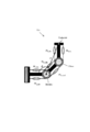
- FIG. 1 It is a block diagram which shows the outline
- (A) is a whole block diagram of a motion analysis apparatus
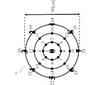
- (B) is a chart which shows an example of an operating point position. It is a figure which shows the muscle which is a musculoskeletal model of an upper limb, and a coordinate system (radial radius R, deflection angle (PHI)). It is a block diagram showing one embodiment of a motion analysis device. It is a flowchart which shows one Embodiment of the procedure of a motion analysis. It is a figure which shows the experimental result of the exercise
- FIG. 7A shows a radial direction
- FIG. 7B shows motion control in a declination direction.
- black points 1 to 25 represent the target positions for maintaining the posture
- large numbers 0 to 8 (9 points) represent the target positions for the periodic reaching movement.
- the motion analysis method estimates a motion command from the central nervous system using feature quantities (muscle synergy, equilibrium point trajectory).
- the physical movement of the exerciser 1 here, a person, is regarded as a mechanical system (musculoskeletal model) of a musculoskeletal structure.
- Information on the musculoskeletal model is preferably stored in advance in the apparatus.
- the exercise of the exerciser 1 is measured as a myoelectric potential and, for example, the position of the operating point (hand tip, end point) of the upper limb.
- the musculoskeletal model, the myoelectric potential, and the position of the limb are obtained as information on the exerciser 1.
- a feature amount is estimated and calculated using these pieces of information.
- the feature quantity is a base vector that describes the equilibrium point of the operating point (hand tip, end point) and the equilibrium point using the concepts of muscle antagonist ratio and muscle antagonistic sum when the body movement is regarded as a mechanical system of musculoskeletal structure. It is a certain muscle synergy and is required analytically.
- the equilibrium point represents a position command from the central nervous system with respect to the operating point.
- muscle synergy is described by components in the radial R direction and the declination ⁇ direction (see FIG. 2).
- FIG. 1 (A) an exerciser 1 (subject) is seated on a chair 3 toward a work desk 2 as shown in a plan view.
- a chart 4 indicating the operating point position is fixedly arranged on the work desk 2 in front of the exerciser 1.
- the chart 4 is composed of, for example, a sheet body, and a plurality of operating point positions 41 (see FIG. 1B) are described in a predetermined arrangement on the surface as will be described later.
- a predetermined number for example, 25 operating point positions 41 are described.
- Various arrangements of the operating point position 41 can be considered.
- the center “1” and the inner circumference “2” to “9” are arranged.
- each circumference is, for example, 5 cm, 10 cm, and 15 cm from the inside.
- the right forearm of the exerciser 1 is supported on a cart 5 (cart) and fixed with a tying member 5a.
- the cart 5 allows the right forearm of the exerciser to slide on the work desk 2 with the influence of gravity removed.
- Various means can be adopted as means for removing the influence of gravity, such as using a hanging member instead of the cart 5.
- the test muscles that are the target site of the motion analysis are 3 to 6 muscles (of which 1 pair is a biarticular muscle) that plays a major role in the upper limb motion in a horizontal plane.
- the definition of the test muscle and the coordinate system is shown in FIG.
- the cart 5 has a portion extending horizontally, and is provided with a grip portion (not shown in the figure) made of a rod-like body standing upright at the tip thereof.
- the exerciser 1 holds the grip portion with the right hand, so that the orientation of the wrist is fixed.
- an optical tracking system such as a motion capture in which a camera 6 as an imaging means is arranged is employed.
- markers 7 are attached to a total of four positions, ie, the left shoulder, right shoulder, and right elbow joint center of the athlete 1 and the top of the rod-shaped body of the grip portion. Is fitted.
- the marker 7 may employ a specific color, for example, a member that emits far infrared light, or a light emitting element.
- the camera 6 images each marker 7 as a bright spot representing position information within the camera field of view.
- the camera 6 is preferably configured to take an image from directly above the chart 4 or directly above or near the athlete 1 from below.
- Each marker 7 at the joint center of the left shoulder and right shoulder of the exerciser 1 and the marker 7 attached to the top of the rod-like body of the grip portion of the cart 5 are used to measure the deflection angle ⁇ information.
- the marker 7 attached to the top of the rod-like body of the grip portion of the cart 5 is the tip position of the upper right limb of the exerciser 1, and the radius R information is measured by the marker 7 on the right shoulder of the exerciser 1. used.
- the bar-like body of the grip portion of the cart 5 has a structure in which the lower end side extends to the vicinity of the work desk 2 to facilitate positioning by visual recognition on the chart 4 or a laser pointer for positioning is provided downward. Also good.
- the measurement process is performed by the position measurement unit 30.
- the other camera 6 is for taking an image of the exerciser 1 during exercise from desired multiple directions to improve exercise measurement accuracy, and is not essential.
- a plurality of electrodes 8 are stuck on the skin of the upper right limb of the athlete 1.
- the plurality of electrodes 8 are attached to the surface side of the muscle shown in FIG. 2 and detect the myoelectric potential generated in the corresponding muscle.
- the musculoskeletal system of 3 to 6 muscles that imitates the human upper limb model is a posterior deltoid muscle, ext, anterior deltoid muscle, ms, flx, from the shoulder to the elbow.
- the muscles ms, ext and ms, flx, the muscles mse, ext and mse, flx, and the muscles me, ext and me, flx are called antagonistic muscle pairs.
- R and ⁇ in the figure indicate the radius and declination in the polar coordinate system with the right shoulder as the origin.
- Myoelectric potential is obtained by EMG (electromyography that directly measures muscle activity: electromyography) measurement and, as a concept, antagonizes the ratio of muscle activities that are considered to be the smallest unit of muscle coordination (muscle antagonistic ratio). It introduces the sum of muscle activities (muscle antagonistic sum).
- the motion analysis apparatus includes a myoelectric potential measuring unit 20 that detects a myoelectric potential of each electrode 8, a signal processing unit 10 to a storage unit 14 that constitute a control unit of a personal computer, and a monitor 152. .
- the motion analysis device detects the exercise position via the myoelectric potential measurement unit 20 that detects the myoelectric potential of the exerciser 1 via the electrode 8 and the marker 7 attached to the exerciser 1.
- the measuring unit 30 includes a signal processing unit 10 composed of a microcomputer or the like that performs predetermined signal processing based on the measured information, and units 11 to 15 related to processing in the signal processing unit 10.
- the myoelectric potential measurement unit 20 includes six electrodes 8, a myoelectric potential detection circuit 21 that detects an electric signal generated at each electrode 8, and a preprocessing circuit 22 that performs predetermined preprocessing on the detected electric signal.
- the myoelectric signal obtained on the body surface is an AC signal having a level of several tens of ⁇ V to several hundreds of ⁇ V and a frequency of about 5 Hz to 500 Hz. Therefore, the preprocessing circuit 22 includes an amplifier that amplifies the myoelectric potential to a level that can be processed (several thousand times), a band-pass filter that passes only signals in the main frequency band of the myoelectric potential, and a full-wave rectifier circuit. .
- the preprocessing circuit 22 includes an AD conversion unit on the output side in order to digitally process the myoelectric potential signal.
- the position measuring unit 30 includes, for example, a camera 6 directly above that detects the marker 7, and a preprocessing circuit 31 that detects a bright spot from an imaging signal from the camera 6 directly above, and the position coordinates of the detected bright spot Predetermined preprocessing such as measuring information is performed.
- the position measurement unit 30 may employ a known measurement device that can detect a three-dimensional position and orientation, which includes a magnetic generator and a magnetic sensor.
- the signal processing unit 10 is composed of a microcomputer having a CPU, and includes a ROM 11 that stores a processing program for signal processing according to the present invention, a RAM 12 that temporarily stores data being processed, and performs necessary instructions.
- a ROM 11 that stores a processing program for signal processing according to the present invention
- a RAM 12 that temporarily stores data being processed, and performs necessary instructions.
- an operation unit 13 including a numeric keypad and a mouse
- a storage unit 14 are provided.
- the storage unit 14 stores various calculation programs, human musculoskeletal model data, and other required data.
- the human musculoskeletal model data may be stored in the ROM 11 or RAM 12.
- a display unit 15 is connected to the signal processing unit 10.
- the display unit 15 includes a display processing unit 151 and a monitor 152.
- the monitor 152 displays input image confirmation and processing results from the operation unit 13 and displays a video image taken by the camera 6.
- the display processing unit 151 associates the processing result of the signal processing unit 10 with the video from the camera 6 and outputs it to the monitor 152 and presents it to the exerciser 1 as necessary.
- the signal processing unit 10 executes the processing program read from the ROM 11 to the RAM 12 to periodically execute the measurement processing of the electrode 8 and the measurement processing of the marker 7 periodically.
- the myoelectric potential measurement processing unit 101 and the position measurement processing unit 102 perform measurement operations in synchronization to acquire corresponding information.
- a method of motion analysis will be described in relation to the description of each function process.
- muscle synergy S T is, [S R, s S R , se S R, e] and [S ⁇ , s S ⁇ , se S ⁇ , e] from muscular synergies vector in radial direction and the polarization angle direction of It is defined by the physical quantity of balance of muscle antagonistic sum, that is, balance of joint stiffness due to co-activity of antagonistic muscles.
- the matrix subscript T indicates a transposed matrix.
- Equation (5) is obtained using Equation (2), Equation (3), and Equation (4).
- Equation (7) all the equations (1) are unknown variables, and the final term (A) corresponds to the three items and the four items on the right side of the equation (6). Four items are measurable variables. Therefore, the term (B) remains as an unknown variable, and this part is put together and set as S ′ T as shown in Equation (7).
- Equation (7) replacing the equation for S 'T, the equation (8).
- the matrix subscript # indicates a pseudo inverse matrix.
- Equation (10) is obtained.
- the measurement by the myoelectric potential measurement unit 20 and the position measurement unit 30 is performed in a state where the exerciser 1 is stationary at a predetermined position on the chart 4.
- the exerciser 1 moves the hand to the operation point, for example, from the operation point “1” on the chart 4 to the operation point “25” in order.
- measurement by the myoelectric potential measuring unit 20 and the position measuring unit 30 is performed by receiving a measurement command from the signal processing unit 10 or the like.
- the measurement at the operating point is completed, the hand is moved toward the next operating point, and the measurement is similarly performed while still. Thereafter, the same operation is repeated until the final operation point “25”.
- Equation (11) is an equation when the operating point is extended to 1 to n (25 points in this embodiment), and Equation (12) is an extension of Equation (10).
- ⁇ is the displacement from the respective time sample average.
- muscle synergy can be expressed as shown in Equations (13) and (14) through some algebraic calculations. Then, knowing the S 'T, see A value and B value, thereby resulting in muscle synergy S T is obtained. In this way, by applying the constraint condition, it is possible to derive a plausible muscle synergy by statistically estimating the part of the unknown variable that is the term (B) in Equation (7).
- this method needs to obtain MVC values in advance using the manual testing method (H.Hislop, J. Montgomery, “New manual muscle testing method” 8th edition, Kyodo Medical Publishing, 2008.). There is no.
- it has an advantage in estimating muscle synergy considering the muscular strength balance unique to an exerciser from statistical analysis.
- this method uses myoelectric potential during posture maintenance that does not require a relatively large muscle force, and the universal end point position and equilibrium point position in such posture maintenance are used.
- the conventional problem is overcome because the physical relationship (the constraint condition) is used. Therefore, the analysis apparatus according to this method is highly practical. In particular, making MVC measurement unnecessary contributes to simplification of work, improvement of estimation accuracy, and reduction of the burden on the subject.
- the drive robot 50 shown in FIG. 3 has, for example, a plurality of actuators for moving a required part of the mechanism body, and can adjust the pneumatic pressure in accordance with an electric signal to expand and contract the pneumatic rubber tube. It is composed of an McKibben type artificial muscle and the like, and a signal corresponding to the feature amount is received (transplanted) to perform an operation.
- the actuator is not limited to the McKibben type artificial muscle, and may be an electromechanical conversion element that changes into a mechanical motion by an electric signal or by another force obtained by converting the electric signal, such as an electromagnetic solenoid, a piezoelectric element, or a motor.
- the control target is a musculoskeletal robot having an artificial muscle arm, for example, an upper limb musculoskeletal robot, a mechanism for generating an artificial muscle activity command that realizes a target hand movement as in the case of the human body is required.
- FIG. 4 is a flowchart showing the procedure of the motion analysis process.
- step S9 it is determined whether or not the measurement process is completed for the variable i> 25, that is, for all operating points (for example, 25 points) (step S9). If the measurement process is not completed, the process returns to step S3, the hand is moved to the next operating point, and the measurement is executed with a manual measurement instruction, for example, in a state where the stationary state is confirmed. On the other hand, when the measurement process is finished, the muscle antagonistic ratio for each antagonistic muscle is calculated from the myoelectric potential signals measured at all the operating points (step S11).
- muscle synergy which is one of the feature values
- muscle synergy calculation unit 104 uses the information on the muscle antagonist ratio and the exercise position and the data of the musculoskeletal model (step S13).
- an equilibrium point which is another feature amount, is calculated by the equilibrium point calculation unit 105 based on information on the muscle antagonist ratio, the exercise position, and the muscle synergy (step S15).
- the two calculated feature quantities are output to the display processing unit 151 (step S17) and displayed on the monitor 152.
- FIG. 5 (A) to FIG. 5 (E) show muscle synergies for each subject's movement in the upper half (a), and each operating point (1 to 25 points) in the lower half (b). The end point position and the corresponding equilibrium point position are shown. Muscle synergy shows the radial R direction component on the left side and the declination ⁇ direction component on the right side, and shows the shoulder, shoulder and elbow (Shoulder & Elbow), and elbow (Elbow) components, respectively. ing.
- the muscle synergy vector estimated this time is the muscle synergy vector estimated by the conventional method (Kanna Uno, Takanori Oku, Keitaro Furuba, Mitsunori Uemura, Hiroaki Hirai, Fumio Miyazaki : Proposal of a new evaluation method for muscle synergy, equilibrium point trajectory and hand stiffness using EMG signals during human upper limb movement in a horizontal plane, “Journal of the Robotics Society of Japan, vol.32, no.7, pp. 603-614, 2014.)), but the balance was different.From Fig. 5 (A) to Fig.
- the equilibrium point position is calculated as an average value of measured values measured a plurality of times in consideration of the variability (shake) of the equilibrium point, for example, as shown in FIG.
- the estimated muscle synergy is calculated as a plausible value that explains the movement from statistical data analysis without making an unreasonable assumption. This result contributes to the development of (1) understanding human movements that control redundant muscle groups, (2) diagnosis of movements for the purpose of rehabilitation, and (3) movement control of robots simulating human musculoskeletal structures. It is considered a thing.
- the muscle synergy vectors of subjects A to E extracted by this analysis method showed high agreement among the five subjects (inner product 0.996 ⁇ in the radial R direction). 0.005, inner product 0.987 ⁇ 0.017 for declination ⁇ direction).
- this muscle synergy extraction method hardly reflects individual differences among subjects, in other words, generality was high.
- FIG. 6 is a diagram showing the variability (vibration) of the equilibrium point, and illustrates a plurality of operating point positions.
- 6A shows fluctuations in the equilibrium points corresponding to the operating point positions 3, 5, 7, and 9 on the inner circumference (in the figure, EP (3), EP (5), EP (7), EP ( 9B), and
- FIG. 6B shows fluctuations in the equilibrium points corresponding to the operating point positions 11, 13, 15, 17 on the intermediate circumference (EP (11), EP (13), EP (15), and EP (17)).
- the equilibrium point with respect to the operating point is a biological signal reflecting a movement command derived from the central nervous system for realizing a desired movement, and has variability.
- This variability can be grasped as a change tendency of the feature amount related to the motion command.
- Variability appears as the size of the variability of the equilibrium point, and is considered to be related to, for example, the patient's symptoms and healing (including rehabilitation) conditions, and is applied to treatment by observing the variability and changes in the time direction. It becomes possible to do.
- the equilibrium point calculation unit 105 may calculate an equilibrium point in a plurality of pieces of measurement information for each operating point and display the equilibrium point on the monitor 152 as illustrated in FIG. 6 via the display processing unit 151.
- the musculoskeletal arm robot 501 for example, the driving robot 50 shown in FIG. 3 is applied. More specifically, as shown in FIG. 7, the musculoskeletal arm robot 501 includes muscles m s, ext and m s, flx between a fixed part and a shoulder (Shoulder), and a shoulder and an elbow (Elbow). The muscles m se, ext and m se , flx are provided between them, and the muscles me , ext , me, flx are provided between the elbow and the hand (EndPoint).
- FIGS. 8A and 8B show the results when the muscle synergy activity coefficients in the radial direction and the declination direction are respectively controlled.
- the muscle synergy activity coefficient in each direction By individually controlling the muscle synergy activity coefficient in each direction, the musculoskeletal arm robot 501 could be controlled almost linearly in the selected direction.
- the W R controlled linearly, during, W [Phi was kept constant.
- a muscle synergy activity coefficient W R and W [Phi is calculated by equation (15).
- the equilibrium point R EP and [Phi EP is estimated by using the muscle synergy activity coefficient W R and W [Phi from the equation (16).
- K R and K [Phi is a gain coefficient
- R 0 and [Phi 0 is the initial position of the time sample mean.
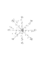
- FIG. 10 shows the actual trajectory Et in the reciprocation between the center position 0 and each of the target positions 1 to 8 in the periodic reaching motion, and the equilibrium point trajectory De obtained periodically during the reaching motion. It is shown.
- the actual trajectory Et represents the actual trajectory of the hand
- the equilibrium point trajectory De indicated by an arrow represents the deviation of the hand equilibrium point position from the hand position.
- FIG. 11 shows a continuous photograph in plan view during the periodic reaching movement of a subject 1, (A) is one reciprocating movement between the center position 0 and the target position 2, (B) Is a frame photograph at intervals of 0.4 milliseconds, for example, during one reciprocal motion between the center position 0 and the target position 5.
- the point hp indicates the hand position of the subject 1
- the point ep indicates the equilibrium point position. It was confirmed that the equilibrium point position ep precedes the hand position hp, and the motion plan is designed to compensate for the dynamic influence of the hand. Further, the features of FIGS. 10 and 11 were obtained in the same manner for other subjects.
- Non-Patent Document 1 shows changes in muscle synergy and equilibrium point trajectory in the recovery process of a stroke patient.
- an equivalent analysis can be easily performed without measuring the MVC value. It will be possible and will be useful for clinical exercise diagnosis and treatment.
- the mode has been described in which the upper limb is exercised on a desk.
- the exercise site may be the lower limb in addition to the upper limb, and a wide range of exercise including whole body exercise in which both the upper limb and the lower limb are linked. It is also applicable to.
- this analysis method and apparatus is based on the condition that the operating point in maintaining posture under gravity compensation matches the equilibrium point at the same operating point.
- the motor strategy to be selected (depending on the motor learning level and individual differences) can be presented to the user objectively and quantitatively based on a clear standard, and a specific means for supporting motor learning can be provided.
- the above-described motion analysis method and device can be applied to a motor control evaluation method and device for elucidating the motion generation mechanism and the motor learning mechanism of healthy persons, for example, brain disease patients.
- a mode in which motor skills are diagnosed and evaluated from the above two feature quantities estimated based on motor commands of the central nervous system and motor learning is promoted through additional feedback is effective in the sports field and the rehabilitation field.
- the two feature quantities obtained by this analysis method can be effectively used for motor control evaluation and motor learning support.
- the motion analysis apparatus includes a myoelectric potential detection unit that detects the myoelectric potential of the exerciser, and a motion detection unit that detects the positions of the limb tips of the exerciser at a plurality of operating point positions.
- the muscle synergy that is the basis vector describing the equilibrium point of the exerciser and the equilibrium point, Computation means for calculating based on a constraint condition and a musculoskeletal model in which the position of the limb tip of the exerciser and the equilibrium point position coincide in posture maintenance under gravity compensation, and the computation means is detected
- Muscle antagonistic ratio calculation means for calculating muscle antagonistic ratio from myoelectric potential
- muscle synergy is calculated from the position of the limb tip detected by the motion detector and the muscle antagonistic ratio calculated by the muscle antagonist ratio calculating means
- Muscle synergy calculation The equilibrium point is calculated from the muscle antagonist ratio calculated by the muscle antagonist ratio calculating means, the position of the limb tip detected by the motion detection unit, and the muscle synergy calculated by the muscle synergy calculating means. It is preferable to provide an equilibrium point calculation means.
- the motor analysis method includes a myoelectric potential detection step for detecting an myoelectric potential of an athlete, a motion detection step for detecting positions of the limb tips of the athlete at a plurality of operating point positions, and the myoelectric potential. From the myoelectric potential detected in the detection step and the position of the tip of the limb detected in the motion detection step, the muscle synergy that is the basis vector describing the balance point of the exerciser and the balance point is calculated under gravity compensation. A calculation step based on a constraint condition and a musculoskeletal model in which the position of the limb tip of the exerciser and the equilibrium point position coincide with each other in posture maintenance, and the calculation step includes calculating a muscle from the detected myoelectric potential.
- the motion analysis program includes a myoelectric potential detection unit that detects an athlete's myoelectric potential and a motion detection unit that detects the position of the limb tip of the exerciser at a plurality of operating point positions.
- Measurement instruction means for instructing detection of a person's myoelectric potential and position of the limb tip, from the myoelectric potential detected by the myoelectric potential detection unit and the position of the limb tip detected by the motion detection unit,
- the muscle synergy that is the basis point describing the equilibrium point and the equilibrium point is based on the constraint condition and the musculoskeletal model in which the position of the limb tip of the athlete matches the position of the equilibrium point in posture maintenance under gravity compensation.
- the motion analysis device functions as a calculation means for calculating, and the calculation means includes a muscle antagonist ratio calculation means for calculating a muscle antagonist ratio from the detected myoelectric potential, and the limb detected by the motion detector.
- a muscle synergy calculating means for calculating muscle synergy from the muscle antagonist ratio calculated by the muscle antagonist ratio calculating means, a muscle antagonist ratio calculated by the muscle antagonist ratio calculating means, and detected by the motion detector It is preferable to include an equilibrium point calculation unit that calculates the equilibrium point from the position of the limb tip and the muscle synergy calculated by the muscle synergy calculation unit.
- the motion measurement can be simplified, and the analysis accuracy can be improved.
- the myoelectric potential detection unit and the movement detection unit detect the myoelectric potential and the position of the limb tip of the exerciser at a plurality of predetermined operating point positions. According to this configuration, by using measurement information at a plurality of positions, the calculation accuracy of the feature amount is improved through statistical estimation.
- the myoelectric potential detection unit and the movement detection unit periodically detect the myoelectric potential of the athlete and the position of the tip of the limb during the posture maintenance, and the calculation means performs an equilibrium for each detection. It is preferable to calculate points. According to this configuration, it is possible to obtain information on the variability of the equilibrium point at the position of the tip of the limb, and it can be used for, for example, rehabilitation treatment or treatment status determination.
- the myoelectric potential detection unit and the motion detection unit may be configured such that the position of the limb tip of the exerciser moves between one operation point position among the plurality of operation point positions and another one operation point position.
- the myoelectric potential and the position of the tip of the limb of the exerciser are periodically detected, and the muscle antagonist ratio calculating means calculates the muscle antagonist ratio from the myoelectric potential periodically detected during the exercise.
- the equilibrium point calculation means calculates an equilibrium point during movement from the muscle synergy calculated by the muscle synergy calculation means, the position of the tip of the limb and the muscle antagonist ratio obtained during the exercise. It is preferable.
- the muscle synergy obtained in a stationary state at a plurality of predetermined positions and the muscle antagonist ratio obtained during exercise in which the position of the limb tip of the exerciser moves between the plurality of positions are used.
- the muscle synergy obtained in a stationary state at a plurality of predetermined positions and the muscle antagonist ratio obtained during exercise in which the position of the limb tip of the exerciser moves between the plurality of positions are used.
- the limb of the exerciser is an upper limb
- the muscle antagonist model is a 3 to 6 musculoskeletal system imitating an upper limb model from a shoulder to an elbow. According to this configuration, the situation of the motion command from the central nervous system that realizes the upper limb motion can be recognized numerically.
- Signal processor (measurement instruction means) 20 Myoelectric potential measurement unit (Myoelectric potential detection unit) 30 Position measurement unit (motion detection unit) 101 Myoelectric potential measurement processing unit (myoelectric potential detection unit) 102 Position measurement processing unit (motion detection unit) 103 muscle antagonist ratio calculation unit (calculation means) 104 Muscle synergy calculation unit (calculation means) 105 Equilibrium point calculation unit (calculation means)
Landscapes
- Health & Medical Sciences (AREA)
- Life Sciences & Earth Sciences (AREA)
- General Health & Medical Sciences (AREA)
- Animal Behavior & Ethology (AREA)
- Veterinary Medicine (AREA)
- Public Health (AREA)
- Biomedical Technology (AREA)
- Medical Informatics (AREA)
- Molecular Biology (AREA)
- Surgery (AREA)
- Physics & Mathematics (AREA)
- Engineering & Computer Science (AREA)
- Pathology (AREA)
- Biophysics (AREA)
- Heart & Thoracic Surgery (AREA)
- Oral & Maxillofacial Surgery (AREA)
- Dentistry (AREA)
- Physiology (AREA)
- Physical Education & Sports Medicine (AREA)
- Epidemiology (AREA)
- Pain & Pain Management (AREA)
- Rehabilitation Therapy (AREA)
- Measurement Of The Respiration, Hearing Ability, Form, And Blood Characteristics Of Living Organisms (AREA)
- Measurement And Recording Of Electrical Phenomena And Electrical Characteristics Of The Living Body (AREA)
Abstract
運動解析装置は、運動者の筋活動を測定する筋電位測定部(20)及び筋電位測定処理部(101)と、身体運動を測定する運動測定部(30)及び運動位置測定処理部(102)と、測定された筋活動と身体運動情報から、運動者の平衡点及び平衡点を記述する基底ベクトルである筋シナジーを、筋骨格モデル及び重力補償下の姿勢保持において運動者の肢先端の終点位置と平衡点位置とが一致するとの拘束条件に基づいて算出する筋拮抗比算出部(103)、筋シナジー算出部(104)及び平衡点算出部(105)を備えた。これにより、MVC動作を不要にして運動計測を簡便にし、かつ解析精度を向上させる。
Description
本発明は、身体適所、例えば肢の先端等の動作点の運動制御に関わる特徴量を算出する運動解析技術に関する。
人口の高齢化が急激に進む現在、人々の健康増進を支援する科学や技術に多くの期待が寄せられている。適切な支援には正しい理論とそれを裏付ける科学的根拠が必要である。力学的に極めて冗長で多自由度の身体運動システムの制御において、中枢神経系がどのように自由度を操作し、筋活動パターンを決定しているのか、また、その制御規範がどのようなものかについては運動制御領域における古典的な未解決問題である。本発明者らは、筋対群の共活性に基づく身体協調性に注目することでヒト随意運動の解析を行ってきた。
本発明者らは、効果的な介入を探索し、その科学的根拠を与える運動解析・評価ツールとして、随意運動時の筋電位信号により身体協調性(筋シナジー)を抽出し、運動実現に向けて中枢神経系が選択する運動戦略(平衡点軌道等の符号化された高次変数の操作)を可視化する運動解析方法を提案した(特許文献1、非特許文献1)。特許文献1及び非特許文献1に記載の運動解析方法は、(1)筋骨格モデルを構成する筋の大きさやバランスが等価である、(2)肩、肘等の各関節のモーメントアームが等しい、(3)各筋のMVC値(最大随意収縮(Maximum Voluntary Contraction))時の筋電位が既知である、という単純化されたモデル(仮定)を用いて生体運動における筋群活動の振る舞いを推定したものである。
H. Hirai, F. Miyazaki, H.Naritomi, K. Koba, T. Oku, K. Uno, M. Uemura, T. Nishi, M. Kageyama and H. I.Krebs, "On the Origin of Muscle Synergies: Invariant Balance in theCo-activation of Agonist and Antagonist Muscle Pairs." Front. Bioeng.Biotechnol., vol.3, no.192, pp.1-16, 2015.
特許文献1及び非特許文献1に記載の運動解析方法は、ある限定された運動については、これらの単純化されたモデルを用いて運動を説明することは可能であるが、一般の生体運動の中には必ずしもこの仮定が充分でない場合がある。特に、前記(3)の仮定は、リハビリテーションを目的とする用途において実用面で一定の限界がある。すなわち、最大随意収縮は、被験者の随意的な最大努力のもとで行う運動である。そのため、出力であるMVC値には様々な外的、内的要因に伴う個人内、個人間での変動が見られ、その変動は運動推定の結果に影響を及ぼす可能性がある。また、高齢者や患者にとって、最大随意収縮動作は負担となり得る。
本発明は、上記に鑑みてなされたもので、MVC動作を不要にして運動計測を簡便にし、かつ解析精度を向上させる運動解析装置、運動解析方法及び運動解析プログラムを提供するものである。
本発明に係る運動解析装置は、運動者の筋電位を検出する筋電位検出部と、前記運動者の肢先端の位置を複数の動作点位置で検出する運動検出部と、前記筋電位検出部で検出された前記筋電位及び前記運動検出部で検出された前記肢先端の位置から、前記運動者の平衡点及び前記平衡点を記述する基底ベクトルである筋シナジーを、重力補償下の姿勢保持において前記運動者の肢先端の位置と前記平衡点位置とが一致する拘束条件及び筋骨格モデルに基づいて算出する演算手段とを備え、前記演算手段は、検出された前記筋電位から筋拮抗比を算出する筋拮抗比算出手段と、前記運動検出部で検出された前記肢先端の位置及び前記筋拮抗比算出手段で算出された前記筋拮抗比から筋シナジーを算出する筋シナジー算出手段と、前記筋拮抗比算出手段で算出された前記筋拮抗比、前記運動検出部で検出された前記肢先端の位置及び前記筋シナジー算出手段で算出された前記筋シナジーから前記平衡点を算出する平衡点算出手段とを備えたものである。
また、本発明に係る運動解析方法は、運動者の筋電位を検出する筋電位検出ステップと、前記運動者の肢先端の位置を複数の動作点位置で検出する運動検出ステップと、前記筋電位検出ステップで検出された前記筋電位及び前記運動検出ステップで検出された前記肢先端の位置から、前記運動者の平衡点及び前記平衡点を記述する基底ベクトルである筋シナジーを、重力補償下の姿勢保持において前記運動者の肢先端の位置と前記平衡点位置とが一致する拘束条件及び筋骨格モデルに基づいて算出する演算ステップとを備え、前記演算ステップは、検出された前記筋電位から筋拮抗比を算出する筋拮抗比算出ステップと、前記運動検出ステップで検出された前記肢先端の位置及び前記筋拮抗比算出ステップで算出された筋拮抗比から筋シナジーを算出する筋シナジー算出ステップと、前記筋拮抗比算出ステップで算出された筋拮抗比、前記運動検出ステップで検出された前記肢先端の位置及び前記筋シナジー算出ステップで算出された筋シナジーから前記平衡点を算出する平衡点算出ステップとを備えたものである。
また、本発明に係る運動解析プログラムは、運動者の筋電位を検出する筋電位検出部、及び前記運動者の肢先端の位置を検出する運動検出部に対して、複数の動作点位置で運動者の筋電位及び肢先端の位置の検出を指示する測定指示手段、前記筋電位検出部で検出された前記筋電位及び前記運動検出部で検出された前記肢先端の位置から、前記運動者の平衡点及び前記平衡点を記述する基底ベクトルである筋シナジーを、重力補償下の姿勢保持において前記運動者の肢先端の位置と前記平衡点位置とが一致する拘束条件及び筋骨格モデルに基づいて算出する演算手段、として運動解析装置を機能させるもので、前記演算手段は、検出された前記筋電位から筋拮抗比を算出する筋拮抗比算出手段と、前記運動検出部で検出された前記肢先端の位置及び前記筋拮抗比算出手段で算出された前記筋拮抗比から筋シナジーを算出する筋シナジー算出手段と、前記筋拮抗比算出手段で算出された筋拮抗比、前記運動検出部で検出された前記肢先端の位置及び前記筋シナジー算出手段で算出された筋シナジーから前記平衡点を算出する平衡点算出手段と備えたものである。
これらの発明によれば、運動者の筋電位及び肢先端の位置が検出される。演算手段は、検出情報から、運動者の平衡点及び平衡点を記述する基底ベクトルである筋シナジーとの2つの特徴量を算出する。2つの特徴量の算出は、筋骨格モデル、及び重力補償下の姿勢保持において運動者の肢先端の位置と前記平衡点位置とが一致する拘束条件に基づいて行われる。そして、前記演算手段の筋シナジー算出手段によって筋シナジーベクトルが算出され、平衡点算出手段によって平衡点が算出される。これによって、従来手法でのMVCの測定を不要にして、運動計測を簡便にし、かつ解析精度を向上させることができる。
本発明によれば、MVC動作を不要にして運動計測を簡便にし、かつ解析精度を向上させることができる。
本発明に係る運動解析方法は、中枢神経系からの運動指令を特徴量(筋シナジー、平衡点軌道)で推定する。本発明では、運動者1、ここでは人の身体運動は筋骨格構造の機械系(筋骨格モデル)として捉える。筋骨格モデルの情報は、好ましくは装置に予め記憶されている。運動者1の運動は、筋電位、及び例えば上肢の動作点(手先、終点)の位置として測定される。その結果、運動者1の情報として、筋骨格モデル、筋電位及び肢の位置が得られる。これらの情報を用いて特徴量が推定演算される。特徴量は、身体運動を筋骨格構造の機械系と捉えるとき、筋拮抗比、筋拮抗和の概念を用いて、動作点(手先、終点)の平衡点、及び平衡点を記述する基底ベクトルである筋シナジーであり、解析的に求められる。平衡点は、動作点に対する中枢神経系からの位置指令を表している。筋シナジーは、本実施形態では、動径R方向及び偏角Φ方向(図2参照)の成分で記述される。
図1(A)において、運動者1(被験者)は、平面視で示すように、作業机2上に向かって椅子3に着席している。運動者1の面前となる作業机2上には、動作点位置を示すチャート4が固定配置されている。チャート4は、例えばシート体で構成され、表面に後述するように複数の動作点位置41(図1(B)参照)が所定の配列で表記されている。チャート4には、図1(B)に示すように、所定数、例えば25点の動作点位置41が表記されている。動作点位置41の配置は、種々の態様が考えられるが、本実施例では、図1(B)に示すように、中心の「1」と、内側の円周上の「2」~「9」と、中間の円周上の「10」から「17」と、外側の円周上の「18」から「25」が動作点位置として配置されている。各円周の径は、例えば内側から5cm、10cm、15cmである。
運動者1の右前腕は、カート5(台車;cart)上に支持され、結束具5aで固定されている。カート5によって、運動者の右前腕は作業机2上で重力の影響を取り除かれた状態で、スライド可能にされている。なお、重力の影響を取り除く手段として、カート5に代えて、例えば吊り下げ部材を利用する等、種々の態様が採用可能である。
運動解析の対象部位となる被験筋は、本実施例では、水平面内の上肢運動で主要な役割を担う3対6筋(うち1対は二関節筋)である。被験筋と座標系の定義は、図2に示している。また、カート5は水平に延設する部位を有し、その先端部に立設した棒状体からなるグリップ部(図では見えていない)が設けられている。運動者1は、このグリップ部を右手で把持することで、手首の向きが固定される。
本実施形態では、撮像手段であるカメラ6を配置したモーションキャプチャー等の光学トラッキングシステム(位置測定部30、図3参照)を採用している。上方から観測可能な位置、本実施例では、運動者1の左肩、右肩、右肘の関節中心、及び前記したグリップ部の棒状体の頂部の計4箇所には、マーカ7が貼着乃至は装着されている。マーカ7は、特定色、例えば遠赤外光を発する部材、あるいは発光素子を採用してもよい。カメラ6は、各マーカ7をカメラ視野内で位置情報を表す輝点として撮像するものである。カメラ6は、好ましくはチャート4の真上又は運動者1の真上乃至は真上近傍から下方を撮像する構成とすることが好ましい。運動者1の左肩、右肩の関節中心の各マーカ7及びカート5のグリップ部の棒状体頂部に取り付けられたマーカ7は、偏角Φ情報を計測するために使用される。カート5のグリップ部の棒状体頂部に取付けられたマーカ7は運動者1の右上肢の手先位置とされて、運動者1の右肩のマーカ7とによって、動径R情報を計測するために使用される。なお、カート5のグリップ部の棒状体は、下端側が作業机2上近くまで延設されて、チャート4上での視認による位置決めを容易にし、あるいは下向きに位置決め用のレーザポインタを設けた構造としてもよい。計測処理は、位置測定部30で行われる。なお、他のカメラ6は、所望する多方向から運動者1の運動中の画像を撮影し、運動計測精度を向上させるためのものであり、必須ではない。
運動者1の右上肢の皮膚上には、複数の電極8が貼着されている。複数の電極8は、図2に示す筋肉の表面側に貼着されて、対応する筋に発生する筋電位を検出する。図2において、ヒトの上肢モデルを模した3対6筋の筋骨格システムは、右肩(Shoulder)から右肘(Elbow)までの、三角筋後部ms,ext、三角筋前部ms,flx、上腕三頭筋長頭mse,ext、上腕二頭筋長頭mse,flx、上腕三頭筋外側頭me,ext、腕橈骨筋me,flxである。ここで、筋ms,extとms,flx、筋mse,extとmse,flx、筋me,extとme,flxとは拮抗筋対という。図中のR,Φは、右肩を原点とした極座標系における動径と偏角を示している。
筋電位は、EMG(筋活動を直接計測する筋電図:electromyography)計測で得られ、概念として、筋協調の最小単位と考える拮抗する筋同士の活動の比(筋拮抗比)と、拮抗する筋同士の活動の和(筋拮抗和)とを導入している。
図1に戻って、運動解析装置は、各電極8の筋電位を検出する筋電位測定部20、パーソナルコンピュータの制御部を構成する信号処理部10~記憶部14、及びモニタ152を備えている。
次に、図3において、運動解析装置は、運動者1の筋電位を電極8を介して検出する筋電位測定部20と、運動者1に取り付けたマーカ7を介して運動位置を検出する位置測定部30と、それぞれの測定した情報に基づいて所定の信号処理を施すマイクロコンピュータ等で構成される信号処理部10と、信号処理部10における処理に関連する各部11~15を備える。
筋電位測定部20は、6個の電極8と、各電極8に生じる電気信号を検出する筋電位検出回路21と、検出された電気信号に対して所定の前処理を施す前処理回路22とを備える。体表で得られる筋電位信号は、レベルが数十μV~数百μV、周波数が5Hz~500Hz程度の交流信号である。そこで、前処理回路22は、筋電位を処理可能なレベル(数千倍)まで増幅するアンプ、筋電位の主要周波数帯の信号のみを通過させるバンドパスフィルタ、及び全波整流回路を備えている。また、前処理回路22は、筋電位信号をデジタルで処理するべく、出力側にAD変換部を備えている。
位置測定部30は、マーカ7を検出する例えば真上のカメラ6と、真上のカメラ6からの撮像信号から輝点を検出する前処理回路31とを備え、検出された輝点の位置座標情報を計測する等の所定の前処理を施す。なお、位置測定部30は、光学的な位置測定の他、磁気発生器と磁気センサとから構成される3次元上の位置と向きが検出可能な公知の測定器を採用してもよい。
信号処理部10は、CPUを有するマイクロコンピュータで構成されており、本発明に係る信号処理のための処理プログラムを記憶するROM11、処理途中のデータを一時的に記憶するRAM12、所要の指示を行うためのテンキーやマウス等で構成される操作部13、及び記憶部14を備えている。記憶部14は、各種の演算プログラム、人体筋骨格モデルのデータその他の所要のデータを記憶する。なお、人体筋骨格モデルのデータは、ROM11又はRAM12内に格納される態様でもよい。
信号処理部10には表示部15が接続されている。表示部15は、表示処理部151とモニタ152とを備える。モニタ152は、ここでは操作部13からの入力情報の確認や処理結果を表示すると共に、カメラ6による撮影映像を表示するものである。表示処理部151は、信号処理部10での処理結果とカメラ6からの映像とを対応付けてモニタ152に出力し、必要に応じて運動者1に提示している。
信号処理部10は、ROM11からRAM12に読み出した処理プログラムを実行することによって、電極8の測定処理を周期的に実行する筋電位測定処理部101と、マーカ7の測定処理を周期的に実行する位置測定処理部102と、筋電位測定処理部101で得られた信号から筋拮抗比を算出する筋拮抗比算出部103と、位置測定処理部102及び筋拮抗比算出部103の出力と筋骨格モデルのデータとから筋シナジーを算出する筋シナジー算出部104と、位置測定処理部102、筋拮抗比算出部103及び筋シナジー算出部104の出力から平衡点を算出する平衡点算出部105として機能する。また、筋電位測定処理部101と位置測定処理部102とは、対応する情報を取得するべく、同期して計測動作を行う。以下、各機能処理の説明に関連して運動解析の方法について説明する。
従来の解析手法では、動作点における動径方向と偏角方向の平衡点の位置を、pEP=(REP,ΦEP)Tとしたとき、変位ΔpEPは、筋拮抗和から成る関数(筋シナジー)STと筋拮抗比偏差Δrj,(j=s,se,e)の線形結合として、式(1)のように表される(宇野かんな、奥貴紀、古場啓太郎、植村充典、平井宏明、宮崎文夫:水平面内におけるヒト上肢運動時のEMG信号を利用した筋シナジー、平衡点軌道および手先剛性の新しい評価法の提案、" 日本ロボット学会誌、vol.32,no.7,pp. 603-614,2014.)。

但し、筋シナジーSTは、[SR,sSR,se SR,e]と[SΦ,s SΦ,se SΦ,e]の動径方向と偏角方向の筋シナジーベクトルからなり、筋拮抗和のバランス、すなわち拮抗筋の共活性による関節剛性のバランスという物理的な量で定義されている。また、[ΔrsΔrse Δre]Tは、各筋拮抗比rj,(j=s,se,e)の時間標本平均からの偏差であり、CR,CΦは、筋骨格系の特性(各筋の特性、リンク長、関節のモーメントアームの径)によって決まる定数である。なお、文中において、行列の添え字Tは、転置行列を示す。
これに対して、本発明に係る解析手法では、上記の式(1)の[ΔrsΔrse Δre]Tを姿勢保持時の各拮抗筋対のEMG(筋電位)mj.ext,mj.flx、MVC値Mj.ext,Mj.flx,(j=s,se,e)を用いて、式(2)、式(3)、式(4)を利用して、式(5)を得る。

そして、式(5)を式(1)に代入すると、式(6)の関係が得られる。

ここで、式(1)は全て未知の変数で、その最終項(A)は、式(6)の右辺の3項目と4項目に該当する。4項目は計測可能な変数である。従って、(B)項が未知変数として残り、この部分をまとめて、式(7)に示すように、S'Tとおく。
さらに、式(7)を、S'Tを求める式に置換すると、式(8)となる。なお、行列の添え字#は、擬似逆行列を示す。
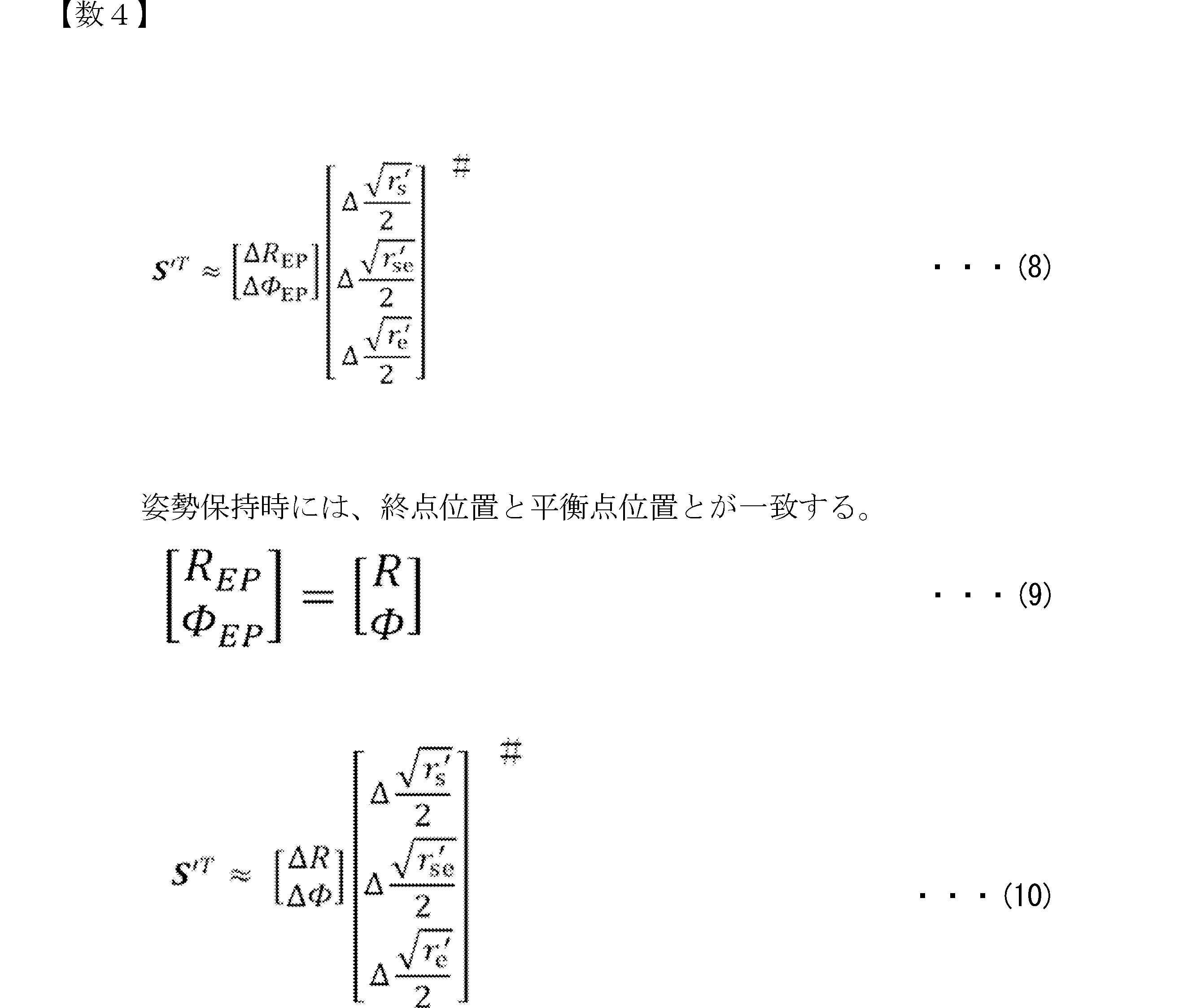
ここで、水平面内の姿勢保持時(静止時)には、手先の終点位置と平衡点位置とが一致するという物理的拘束条件に従って、式(9)が成立するから、この関係を式(8)に適用すると、式(10)が得られる。
本発明に係る解析手法では、筋電位測定部20と位置測定部30とによる計測は、チャート4上の所定位置で運動者1が手先を静止させている状態で行う。計測に際して、運動者1は動作点に、チャート4上の、例えば動作点「1」から順番に動作点「25」まで手先を移動する。ある動作点に移動したら、その動作点で静止し、その間に、信号処理部10からの計測指令を受ける等して筋電位測定部20と位置測定部30とによる計測が行われる。その動作点での計測が終了すると、次の動作点に向けて手先を移動し、同様に静止して測定を行う。以下、最終の動作点「25」まで同様な動作が繰り返される。
式(11)は、動作点が1~n(本実施例では、25点)に拡張された場合の式で、式(12)は式(10)を拡張したものである。
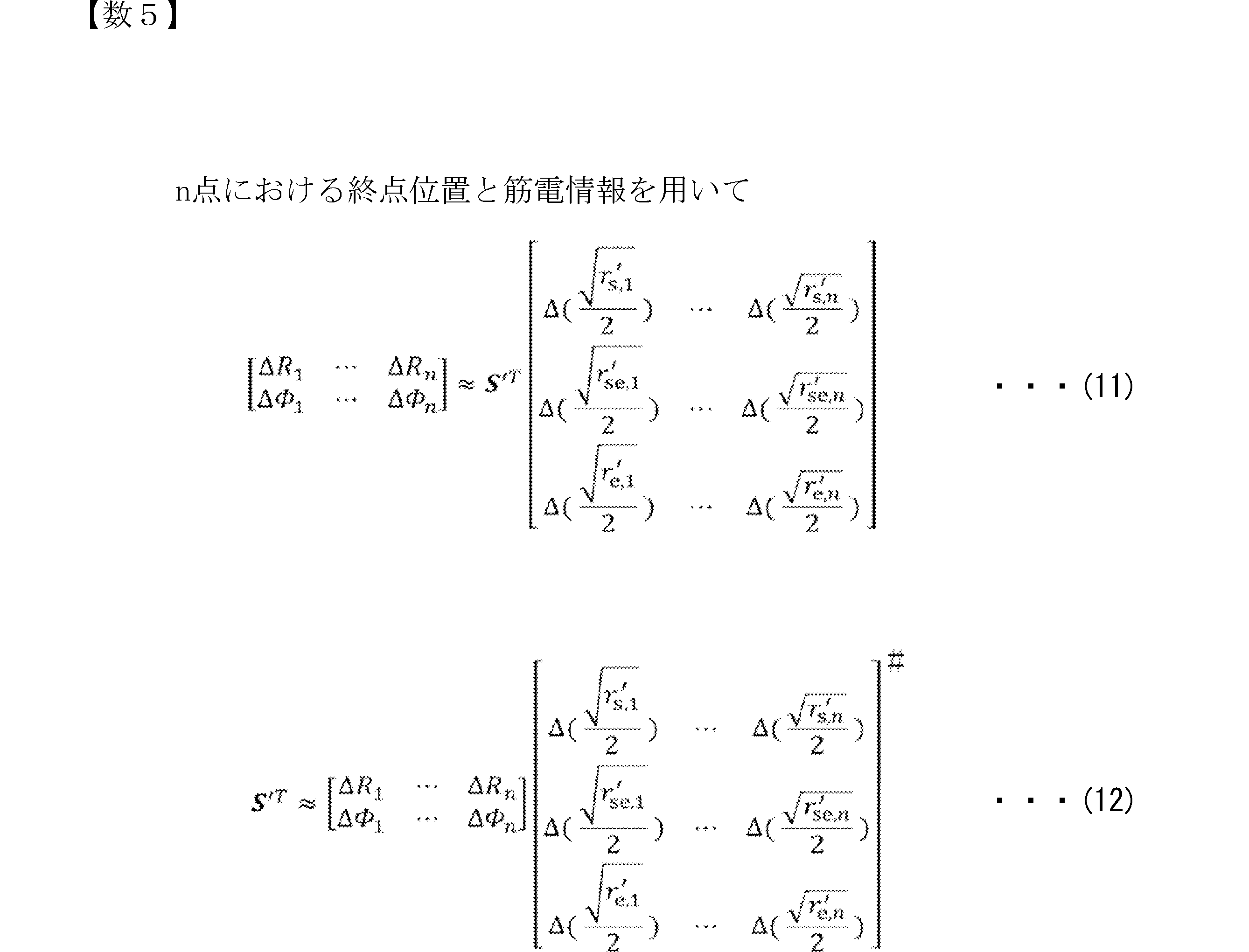
Δは、それぞれの時間標本平均からの変位である。説明上、詳細は省略するが、幾らかの代数計算を経て、筋シナジーは、式(13)、式(14)で示すように表現することができる。そして、S'Tが分かれば、A値及びB値が分かり、それによって、筋シナジーSTが求まることになる。このように、前記拘束条件を適用することで、式(7)の(B)項である未知変数の部分を統計的に推定することで、尤もらしいし筋シナジーを導出することができる。

ここで、式(13)には、M'j,(j=s,se,e)が含まれていないことが認められる。すなわち、本手法は、徒手検査法等( H.Hislop, J. Montgomery、”新・徒手筋力検査法”原著第8版、協同医書出版社, 2008.)を用いて予めMVC値を取得する必要がない。しかも、統計解析より運動者固有の筋力バランスを考慮した筋シナジーを推定する点において利点を有している。
このように、本手法は、MVC測定とは異なり、比較的大きな筋力を必要としない姿勢保持時の筋電位を利用するものあり、かつ、かかる姿勢保持における終点位置と平衡点位置との普遍な物理的関係性(前記拘束条件)を利用することから、従来の課題を克服している。従って、本手法による解析装置は実用性の高いものとなる。特にMVCの計測を不要とすることは、作業の簡易化、推定精度の向上、被験者の負担軽減に貢献する。
なお、図3に示す駆動ロボット50は、例えば、機構体の所要部位を運動させるための複数のアクチュエータを有するもので、電気信号に応じて空圧を調整し、空気圧ゴムチューブを伸張、収縮可能にするMcKibben型人工筋肉等で構成されており、前記特徴量に応じた信号が受信(移植)されて、動作を行う。アクチュエータは、McKibben型人工筋肉に限定されず、電気信号で、あるいは電気信号を変換した別の力によって機械的運動に変える電気機械変換素子、例えば電磁ソレノイド、圧電素子、モータ等であってもよい。制御対象が、人工筋アームを備えた筋骨格ロボット、例えば上肢筋骨格ロボットである場合、人体の場合と同様に目標手先運動を実現する人工筋活動コマンドを生成するメカニズムが必要となる。
図4は、運動解析処理の手順を示すフローチャートである。まず、動作点の番号を表す変数iがi=0にセットされ(ステップS1)、次いで、変数iが1だけインクリメントされて(ステップS3)、最初の動作点に対して筋電位測定部20、位置測定部30から筋電位の検出信号、運動位置の信号が取り込まれ(ステップS5)、これらの信号から筋電位の測定処理、運動位置等の測定処理が実行される(ステップS7)。
続いて、変数i>25、すなわち全ての動作点(例えば25点)について、計測処理が終了したか否かが判断される(ステップS9)。計測処理が終了していない場合、ステップS3に戻って次の動作点に手先が移動され、静止が確認された状態で、例えばマニュアルによる計測指示がなされて計測が実行される。一方、計測処理が終了した場合、全ての動作点で測定された筋電位信号から拮抗筋毎の筋拮抗比が算出される(ステップS11)。
続いて、筋拮抗比及び運動位置の情報と筋骨格モデルのデータとを用いて、筋シナジー算出部104より特徴量の1つである筋シナジーが算出される(ステップS13)。さらに、筋拮抗比、運動位置及び筋シナジーの情報に基づいて、平衡点算出部105より特徴量の他の1つである平衡点が算出される(ステップS15)。これら算出された2つの特徴量は、表示処理部151に出力されて(ステップS17)、モニタ152に表示される。
次に、効果確認のための実験Iについて説明する。
(1)実験I
実験設備は、図1に示す装置を用いる。5人(A~E)の被験者のそれぞれに、図1の装置を用いてチャート4の25点に対して、1番から25番まで順番に手先を移動させ、静止するように指示した。静止中に筋電位測定部20及び位置測定部30を動作させて、各筋のEMGと手先位置とを計測した。各所定位置で姿勢保持した静止時における筋電位測定部20及び位置測定部30の計測は、例えば100Hzで、10秒で行った。
実験設備は、図1に示す装置を用いる。5人(A~E)の被験者のそれぞれに、図1の装置を用いてチャート4の25点に対して、1番から25番まで順番に手先を移動させ、静止するように指示した。静止中に筋電位測定部20及び位置測定部30を動作させて、各筋のEMGと手先位置とを計測した。各所定位置で姿勢保持した静止時における筋電位測定部20及び位置測定部30の計測は、例えば100Hzで、10秒で行った。
(2)結果
図5(A)~図5(E)は、上半部(a)に各被験者の運動に対する筋シナジーを示し、下半部(b)に各動作点(1~25点)における終点位置と対応する平衡点の位置とを示している。筋シナジーは、左側に動径R方向成分を、右側に偏角φ方向成分を示すと共に、それぞれについて、肩(Shoulder)、肩及び肘(Shoulder & Elbow)、肘(Elbow)の各成分を示している。
図5(A)~図5(E)は、上半部(a)に各被験者の運動に対する筋シナジーを示し、下半部(b)に各動作点(1~25点)における終点位置と対応する平衡点の位置とを示している。筋シナジーは、左側に動径R方向成分を、右側に偏角φ方向成分を示すと共に、それぞれについて、肩(Shoulder)、肩及び肘(Shoulder & Elbow)、肘(Elbow)の各成分を示している。
平衡点の位置は、筋シナジーと筋拮抗比とを用いて算出した。図5(A)~図5(E)より、今回推定された筋シナジーベクトルは、従来手法によって推定された筋シナジーベクトル((宇野かんな、奥貴紀、古場啓太郎、植村充典、平井宏明、宮崎文夫:水平面内におけるヒト上肢運動時のEMG信号を利用した筋シナジー、平衡点軌道および手先剛性の新しい評価法の提案、" 日本ロボット学会誌、vol.32,no.7,pp. 603-614,2014.))と同符号であるが、そのバランスが異なっていた。図5(A)~図5(E)より、終点位置と平衡点位置とが概ね近い場所にあることが確認できた。なお、平衡点位置は、例えば図6に示すように平衡点の変動性(振れ)を考慮して、複数回計測された計測値の平均値として算出されている。
(3)考察
推定された筋シナジーベクトルは、被験者固有の筋力バランスを考慮して推定できているため、筋がすべて等価としていた従来手法とは異なるバランスになったと考えられる。
推定された筋シナジーベクトルは、被験者固有の筋力バランスを考慮して推定できているため、筋がすべて等価としていた従来手法とは異なるバランスになったと考えられる。
また、推定される筋シナジーは、無理な仮定を置くことなく、統計的なデータ解析から運動を説明する尤もらしい値として算出される。本結果は、(1)冗長筋群を制御するヒトの運動理解、(2)リハビリテーションを目的とした運動の診断、(3)ヒトの筋骨格構造を模したロボットの運動制御の発展に貢献するものと考えられる。
さらに、表1に示すように、本解析法で抽出された被験者A~Eの各筋シナジーベクトルは、5名の被験者間でそれぞれ高い一致を示した(動径R方向について内積0.996±0.005、偏角φ方向について内積0.987±0.017)。

これにより、この筋シナジー抽出法には被験者間の個人差がほとんど反映されないと考えられ、換言すれば一般性が高いことがわかった。
また、図6は、平衡点の変動性(振れ)を示す図で、複数の動作点位置を例示している。図6(A)は、内側円周上の動作点位置3,5,7,9に対応する平衡点の変動(図中、EP(3),EP(5),EP(7),EP(9)で示す。)についてのものであり、図6(B)は、中間円周上の動作点位置11,13,15,17に対応する平衡点の変動(図中、EP(11),EP(13),EP(15),EP(17)で示す。)についてのものである。
動作点に対する平衡点は、所望の運動を実現するための中枢神経系由来の運動指令を反映した生体信号であって、変動性を有している。この変動性は、運動指令に関する特徴量の変化傾向として捉えることができる。変動性は、平衡点のばらつきの大小として現れ、例えば患者の症状、治癒(リハビリテーション含む)状況に関連するものと考えられ、変動性、またその時間方向の変化を観察することで、治療に適用することが可能となる。
平衡点算出部105は、動作点毎の複数の計測情報における平衡点を算出し、表示処理部151を介して、図6に示すようにモニタ152に表示するようにしてもよい。
次に、ヒト上肢モデルを模した3対6筋の筋骨格アームロボットを用いて、推定した筋シナジーベクトルの妥当性を検証した。なお、筋骨格アームロボット501として、例えば図3に示す駆動ロボット50を適用した。より詳細には、筋骨格アームロボット501は、図7に示すように、固定部と肩(Shoulder)との間に筋ms,extとms,flxが、肩と肘(Elbow)との間に筋mse,extとmse,flxが、肘と手先(EndPoint)との間に筋me,extとme,flxが設けられた構造を有する。
なお、より詳細な構成は、以下の通り、
モーメントアーム:すべて48[mm]
アームの長さ:すべて264[mm]
全体の質量:1.7[kg]
人工筋:すべてMcKibben型空気圧式人工筋(神田通信工業製のタイプ1.0[inch])
空気圧制御装置:フェスト社(株)の空気圧サーボシステム
エアコンプレッサー:JUN-AIR, JUNAIR12-25
DAボード:PCI-3346A,PCI3522A(インターフェイス(株))
空気圧の制御には空気圧制御装置を用いた。この空気圧制御装置は入力する電圧に応じて空気圧をコントロールするサーボ電磁弁を搭載しており、供給圧力を制御するためにコンピュータからの指令電圧をDAボードを介して空気圧制御装置へ送った。また、圧縮空気の供給にはエアコンプレッサーを使用した。
モーメントアーム:すべて48[mm]
アームの長さ:すべて264[mm]
全体の質量:1.7[kg]
人工筋:すべてMcKibben型空気圧式人工筋(神田通信工業製のタイプ1.0[inch])
空気圧制御装置:フェスト社(株)の空気圧サーボシステム
エアコンプレッサー:JUN-AIR, JUNAIR12-25
DAボード:PCI-3346A,PCI3522A(インターフェイス(株))
空気圧の制御には空気圧制御装置を用いた。この空気圧制御装置は入力する電圧に応じて空気圧をコントロールするサーボ電磁弁を搭載しており、供給圧力を制御するためにコンピュータからの指令電圧をDAボードを介して空気圧制御装置へ送った。また、圧縮空気の供給にはエアコンプレッサーを使用した。
筋骨格アームロボット501に筋シナジーSTの動径R成分[SR,sSR,se SR,e]と偏角Φ成分 [SΦ,s SΦ,se SΦ,e]の移植を行い、動径・偏角方向の筋シナジー活性係数をそれぞれ制御した際の、手先の変位を計測した。
図8(A)、(B)は、動径方向と偏角方向の筋シナジー活性係数をそれぞれ制御した際の結果を示している。各方向の筋シナジー活性係数を個別に制御することで、筋骨格アームロボット501を選択した方向へほぼ線形に制御することができた。
なお、図8(A)の、動径方向の筋シナジーベクトル[SR,s SR,se SR,e]制御において、(1)は、筋シナジー活性係数WΦ=―0.2の場合、(2)は、筋シナジー活性係数WΦ=0の場合、(3)は、筋シナジー活性係数WΦ=0.2の場合である。WRを線形に制御し、その間、WΦは一定とした。また、図8(B)の、偏角方向の筋シナジーベクトル[SΦ,sSΦ,se SΦ,e]制御について、(1)は、筋シナジー活性係数WR=―0.2の場合、(2)は、筋シナジー活性係数WR=0の場合、(3)は、筋シナジー活性係数WR=0.2の場合である。WΦを線形に制御し、その間、WRは一定とした。従って、図8(A)(B)の結果は本手法の妥当性を示しており、推定した筋シナジーベクトルが、動径・偏角方向に対して確かに機能していることが分かる。なお、図8(A)(B)の左端の各図は、筋シナジー活性係数WΦ、筋シナジー活性係数WRがある値を採ったときの、動作点(手先、終点)の移動(3点)状況の一例を示したものである。
上記において、筋シナジー活性係数WRとWΦとは、式(15)で求められる。なお、平衡点REPとΦEPは、式(16)より筋シナジー活性係数WRとWΦとを用いて推定される。ここで、KRとKΦはゲイン係数であり、R0とΦ0は時間標本平均としての初期位置である。


ところで、先に説明した実験Iは、静止時の平衡点推定の効果確認に対するものであったが、次に、運動時の平衡点推定の効果の有無を確認する実験IIについて説明する。
(1)実験II
実験設備は、図1に示す装置を用いた。5人(A~E)の被験者のそれぞれに、図1の装置を用いて行った。使用するチャートは、本実施形態では、図9に示すチャート40とした。このチャート40は、図1(B)のチャート4の中心位置と最外周の目標位置とに大サイズの数字0~8が併記されたものを用いた。
実験設備は、図1に示す装置を用いた。5人(A~E)の被験者のそれぞれに、図1の装置を用いて行った。使用するチャートは、本実施形態では、図9に示すチャート40とした。このチャート40は、図1(B)のチャート4の中心位置と最外周の目標位置とに大サイズの数字0~8が併記されたものを用いた。
(2)手順
運動態様としては、一般的な、周期的な到達運動を採用した。実験IIは、チャート40の大サイズの数字0で示す中心位置0と各数字1~8で示す目標位置1~8との間での到達運動(往復運動)とした。すなわち、被験者は、中心位置0と各目標位置1~8と間での連続的な到達運動を行った。詳細には、到達運動は、まず、中心位置0と目標位置1との間で往復運動し、かかる動作を中心位置0と目標位置2,3,…,8との間で順番に変更しながら連続的に行った。往動、復動は、一般的な速度で、例えばメトロノーム(60もしくは80bmp)に合わせて行った。
運動態様としては、一般的な、周期的な到達運動を採用した。実験IIは、チャート40の大サイズの数字0で示す中心位置0と各数字1~8で示す目標位置1~8との間での到達運動(往復運動)とした。すなわち、被験者は、中心位置0と各目標位置1~8と間での連続的な到達運動を行った。詳細には、到達運動は、まず、中心位置0と目標位置1との間で往復運動し、かかる動作を中心位置0と目標位置2,3,…,8との間で順番に変更しながら連続的に行った。往動、復動は、一般的な速度で、例えばメトロノーム(60もしくは80bmp)に合わせて行った。
(3)アルゴリズム
姿勢保持の実験Iで、中心の動作点位置1及び動作点位置18~25(実験IIにおける中心位置0及び目標位置1~8と一致する位置)での筋シナジーS'Tを推定し、次いで、姿勢保持の場合と運動中の場合とで筋シナジーが変わらないことを利用して、平衡点算出部105によって、姿勢保持の実験Iより推定された筋シナジーS'Tと、実験IIの到達運動中から得られる筋拮抗比rj'とを用いて、式(15)及び式(16)より、運動時の平衡点を推定した。基本的には、姿勢保持の場合と同じあり、使用される筋拮抗比rj'が姿勢保持時の筋拮抗比から、到達運動時の筋拮抗比に置換された点で相違する。
姿勢保持の実験Iで、中心の動作点位置1及び動作点位置18~25(実験IIにおける中心位置0及び目標位置1~8と一致する位置)での筋シナジーS'Tを推定し、次いで、姿勢保持の場合と運動中の場合とで筋シナジーが変わらないことを利用して、平衡点算出部105によって、姿勢保持の実験Iより推定された筋シナジーS'Tと、実験IIの到達運動中から得られる筋拮抗比rj'とを用いて、式(15)及び式(16)より、運動時の平衡点を推定した。基本的には、姿勢保持の場合と同じあり、使用される筋拮抗比rj'が姿勢保持時の筋拮抗比から、到達運動時の筋拮抗比に置換された点で相違する。
(3)結果
図10は、周期的な到達運動における、中心位置0と各目標位置1~8との間の往復での実軌道Etと、到達運動中に周期的に得た平衡点軌道Deとを示したものである。実軌道Etは手先の実軌道を表し、矢印で示す平衡点軌道Deは手先の平衡点位置の手先位置からの偏差を表している。図11は、ある被験者1の周期的な到達運動途中における、平面視の連続写真を示すもので、(A)は中心位置0と目標位置2との間の1往復の運動中、(B)は中心位置0と目標位置5との間の1往復分の運動中における、例えば0.4ミリ秒間隔でのコマ写真である。図中、点hpは被験者1の手先位置を、点epは平衡点位置を示している。なお、平衡点位置epは手先位置hpに先行し、手先の動的影響を補償するように運動計画されていることが確認された。また、図10、図11の特徴は、他の被験者についても同様に得られた。
図10は、周期的な到達運動における、中心位置0と各目標位置1~8との間の往復での実軌道Etと、到達運動中に周期的に得た平衡点軌道Deとを示したものである。実軌道Etは手先の実軌道を表し、矢印で示す平衡点軌道Deは手先の平衡点位置の手先位置からの偏差を表している。図11は、ある被験者1の周期的な到達運動途中における、平面視の連続写真を示すもので、(A)は中心位置0と目標位置2との間の1往復の運動中、(B)は中心位置0と目標位置5との間の1往復分の運動中における、例えば0.4ミリ秒間隔でのコマ写真である。図中、点hpは被験者1の手先位置を、点epは平衡点位置を示している。なお、平衡点位置epは手先位置hpに先行し、手先の動的影響を補償するように運動計画されていることが確認された。また、図10、図11の特徴は、他の被験者についても同様に得られた。
(4)考察
周期的な到達運動中、平衡点軌道は、運動の動的影響を受ける手先実軌道Etが直線性を満たすように歪められていた。これは、図10において平衡点位置を示す矢印Deが概ね目標方向を指し示すものの、正確にはその方向が運動相(例えば、中心位置0からいずれかの目標位置への到達運動中における初期、中期、後期の相をいう)毎にわずかに逸れていることから確認できる。本結果は、運動中に動的影響を受ける実軌道Etが、直線的になるなどの所望の条件を満足するように、予め平衡点軌道Deが計画されており、実軌道Etに先行して運動することを示している。換言すれば、人の運動制御において、中枢神経系は動的環境の内部モデルを形成し、運動計画を行っていることを示唆している。本発明によれば、内部処理(筋シナジー、平衡点軌道)を可視化することが可能になる。例えば、先行研究(非特許文献1)で脳卒中患者の回復過程における筋シナジー、平衡点軌道の変化を示しているが、本発明では、MVC値を計測することなく、簡便に、同等の解析が可能になり、臨床での運動診断や治療に有益となる。
周期的な到達運動中、平衡点軌道は、運動の動的影響を受ける手先実軌道Etが直線性を満たすように歪められていた。これは、図10において平衡点位置を示す矢印Deが概ね目標方向を指し示すものの、正確にはその方向が運動相(例えば、中心位置0からいずれかの目標位置への到達運動中における初期、中期、後期の相をいう)毎にわずかに逸れていることから確認できる。本結果は、運動中に動的影響を受ける実軌道Etが、直線的になるなどの所望の条件を満足するように、予め平衡点軌道Deが計画されており、実軌道Etに先行して運動することを示している。換言すれば、人の運動制御において、中枢神経系は動的環境の内部モデルを形成し、運動計画を行っていることを示唆している。本発明によれば、内部処理(筋シナジー、平衡点軌道)を可視化することが可能になる。例えば、先行研究(非特許文献1)で脳卒中患者の回復過程における筋シナジー、平衡点軌道の変化を示しているが、本発明では、MVC値を計測することなく、簡便に、同等の解析が可能になり、臨床での運動診断や治療に有益となる。
なお、本実施形態及び実験I,IIでは、動作点位置等の個数、配置を図1(B)、図9のように示したが、これに限定されず、種々の個数、配置が採用可能である。例えば、所望の肢の運動範囲を偏りなくカバーする十分な個数があればランダムな配置でもよい。
また、前記実施形態等では、上肢を机上で運動させる態様で説明したが、運動部位は、上肢の他、下肢でもよく、また上肢と下肢との双方を連動させた全身運動を含む広範な運動にも適用可能である。すなわち、本解析方法及び装置は、重力補償下の姿勢保持における動作点と同動作点における平衡点とが一致する条件に基づき、より広範な運動に対し、さらに運動状態に対して中枢神経系が選択する運動戦略(運動学習度や個人差に依存)を明確な基準の下、客観的かつ定量的に使用者へ提示し、運動学習支援のための具体的な手段を提供し得る。動作例としては、用途に応じて種々想定され得るが、各種スポーツの動きや技の学習、また、スポーツ以外の動きや立ち振る舞いの習得等にも適用可能である。すなわち、目標課題に対する効果的な運動訓練法や運動介入法の確立へ向けた運動学習支援方法、装置への適用では、例えば、予め模範者の運動時に特徴量を取得しておき、これを参考にして練習者は自己の特徴量を模範者に近づけるよう練習する練習支援である。あるいは、自己の特徴量の練習毎の変化を観察しながら練習する練習支援である。
また、前述の運動解析方法及び装置は、健常者や例えば脳疾患患者の運動生成機序や運動学習機序の解明へ向けた運動制御の評価方法、装置にも適用可能である。中枢神経系の運動指令に基づき推定される上記2つの特徴量から運動技能を診断評価し、附加的フィードバックを介して運動学習の促進を図る態様は、スポーツ分野及びリハビリテーション分野において有効的である。このように、本解析方法により得られた2つの特徴量は、運動制御評価、運動学習支援に効果的に利用され得る。
また、ヒトと物理的な相互作用を伴う機械、道具及び環境の設計と評価を目的としたインタフェース評価装置にも適用可能である。
以上説明したように、本発明に係る運動解析装置は、運動者の筋電位を検出する筋電位検出部と、前記運動者の肢先端の位置を複数の動作点位置で検出する運動検出部と、前記筋電位検出部で検出された前記筋電位及び前記運動検出部で検出された前記肢先端の位置から、前記運動者の平衡点及び前記平衡点を記述する基底ベクトルである筋シナジーを、重力補償下の姿勢保持において前記運動者の肢先端の位置と前記平衡点位置とが一致する拘束条件及び筋骨格モデルに基づいて算出する演算手段とを備え、前記演算手段は、検出された前記筋電位から筋拮抗比を算出する筋拮抗比算出手段と、前記運動検出部で検出された前記肢先端の位置及び前記筋拮抗比算出手段で算出された前記筋拮抗比から筋シナジーを算出する筋シナジー算出手段と、前記筋拮抗比算出手段で算出された前記筋拮抗比、前記運動検出部で検出された前記肢先端の位置及び前記筋シナジー算出手段で算出された前記筋シナジーから前記平衡点を算出する平衡点算出手段とを備えることが好ましい。
また、本発明に係る運動解析方法は、運動者の筋電位を検出する筋電位検出ステップと、前記運動者の肢先端の位置を複数の動作点位置で検出する運動検出ステップと、前記筋電位検出ステップで検出された前記筋電位及び前記運動検出ステップで検出された前記肢先端の位置から、前記運動者の平衡点及び前記平衡点を記述する基底ベクトルである筋シナジーを、重力補償下の姿勢保持において前記運動者の肢先端の位置と前記平衡点位置とが一致する拘束条件及び筋骨格モデルに基づいて算出する演算ステップとを備え、前記演算ステップは、検出された前記筋電位から筋拮抗比を算出する筋拮抗比算出ステップと、前記運動検出ステップで検出された前記肢先端の位置及び前記筋拮抗比算出ステップで算出された筋拮抗比から筋シナジーを算出する筋シナジー算出ステップと、前記筋拮抗比算出ステップで算出された筋拮抗比、前記運動検出ステップで検出された前記肢先端の位置及び前記筋シナジー算出ステップで算出された筋シナジーから前記平衡点を算出する平衡点算出ステップとを備えることが好ましい。
また、本発明に係る運動解析プログラムは、運動者の筋電位を検出する筋電位検出部、及び前記運動者の肢先端の位置を検出する運動検出部に対して、複数の動作点位置で運動者の筋電位及び肢先端の位置の検出を指示する測定指示手段、前記筋電位検出部で検出された前記筋電位及び前記運動検出部で検出された前記肢先端の位置から、前記運動者の平衡点及び前記平衡点を記述する基底ベクトルである筋シナジーを、重力補償下の姿勢保持において前記運動者の肢先端の位置と前記平衡点位置とが一致する拘束条件及び筋骨格モデルに基づいて算出する演算手段、として運動解析装置を機能させるもので、前記演算手段は、検出された前記筋電位から筋拮抗比を算出する筋拮抗比算出手段と、前記運動検出部で検出された前記肢先端の位置及び前記筋拮抗比算出手段で算出された前記筋拮抗比から筋シナジーを算出する筋シナジー算出手段と、前記筋拮抗比算出手段で算出された筋拮抗比、前記運動検出部で検出された前記肢先端の位置及び前記筋シナジー算出手段で算出された筋シナジーから前記平衡点を算出する平衡点算出手段と備えることが好ましい。
これらの発明によれば、従来手法でのMVCの測定を不要にして、運動計測を簡便にし、かつ解析精度を向上させることが可能となる。
また、前記筋電位検出部及び前記運動検出部は、予め定めた複数の動作点位置で、前記運動者の筋電位及び肢先端の位置を検出することが好ましい。この構成によれば、複数の位置での測定情報を利用することで統計的推定を経て特徴量の算出精度は向上する。
また、前記筋電位検出部及び前記運動検出部は、前記運動者の筋電位及び肢先端の位置を前記姿勢保持の間に周期的に検出するものであり、前記演算手段は、検出毎の平衡点を算出することが好ましい。この構成によれば、肢先端の位置における平衡点の変動性の情報を得ることができ、例えばリハビリテーションの治療や治療状況の判断に活用することが可能となる。
また、前記筋電位検出部及び前記運動検出部は、前記運動者の肢先端の位置が前記複数の動作点位置のうちの1つの動作点位置と他の1つの動作点位置との間で運動を行う運動中に、前記運動者の筋電位及び肢先端の位置を周期的に検出し、前記筋拮抗比算出手段は、前記運動中に周期的に検出された前記筋電位から筋拮抗比の算出を行い、前記平衡点算出手段は、前記筋シナジー算出手段で算出された前記筋シナジー、前記肢先端の位置及び前記運動中に得られた筋拮抗比から、動作中における平衡点を算出するものであることが好ましい。この構成によれば、所定の複数の位置で静止した状態で得た筋シナジーと、運動者の肢先端の位置が複数の位置の間を運動する運動中に得られる筋拮抗比とを利用して、運動中における平衡点を得ることが可能となり、汎用性が向上する。
また、本発明は、前記運動者の肢は上肢であり、前記筋拮抗モデルは、肩から肘までの上肢モデルを模した3対6筋の筋骨格システムであることが好ましい。この構成によれば、上肢運動を実現する中枢神経系からの運動指令の状況を数値によって認識することができる。
6 カメラ
8 電極
10 信号処理部(測定指示手段)
20 筋電位測定部(筋電位検出部)
30 位置測定部(運動検出部)
101 筋電位測定処理部(筋電位検出部)
102 位置測定処理部(運動検出部)
103 筋拮抗比算出部(演算手段)
104 筋シナジー算出部(演算手段)
105 平衡点算出部(演算手段)
8 電極
10 信号処理部(測定指示手段)
20 筋電位測定部(筋電位検出部)
30 位置測定部(運動検出部)
101 筋電位測定処理部(筋電位検出部)
102 位置測定処理部(運動検出部)
103 筋拮抗比算出部(演算手段)
104 筋シナジー算出部(演算手段)
105 平衡点算出部(演算手段)
Claims (7)
- 運動者の筋電位を検出する筋電位検出部と、
前記運動者の肢先端の位置を複数の動作点位置で検出する運動検出部と、
前記筋電位検出部で検出された前記筋電位及び前記運動検出部で検出された前記肢先端の位置から、前記運動者の平衡点及び前記平衡点を記述する基底ベクトルである筋シナジーを、重力補償下の姿勢保持において前記運動者の肢先端の位置と前記平衡点位置とが一致する拘束条件及び筋骨格モデルに基づいて算出する演算手段とを備え、
前記演算手段は、
検出された前記筋電位から筋拮抗比を算出する筋拮抗比算出手段と、
前記運動検出部で検出された前記肢先端の位置及び前記筋拮抗比算出手段で算出された前記筋拮抗比から筋シナジーを算出する筋シナジー算出手段と、
前記筋拮抗比算出手段で算出された前記筋拮抗比、前記運動検出部で検出された前記肢先端の位置及び前記筋シナジー算出手段で算出された前記筋シナジーから前記平衡点を算出する平衡点算出手段とを備えた運動解析装置。 - 前記筋電位検出部及び前記運動検出部は、予め定めた複数の動作点位置で、前記運動者の筋電位及び肢先端の位置を検出することを特徴とする請求項1に記載の運動解析装置。
- 前記筋電位検出部及び前記運動検出部は、前記運動者の筋電位及び肢先端の位置を前記姿勢保持の間に周期的に検出するものであり、前記演算手段は、検出毎の平衡点を算出することを特徴とする請求項1又は2に記載の運動解析装置。
- 前記筋電位検出部及び前記運動検出部は、前記運動者の肢先端の位置が前記複数の動作点位置のうちの1つの動作点位置と他の1つの動作点位置との間で運動を行う運動中に、前記運動者の筋電位及び肢先端の位置を周期的に検出し、
前記筋拮抗比算出手段は、前記運動中に周期的に検出された前記筋電位から筋拮抗比の算出を行い、
前記平衡点算出手段は、前記筋シナジー算出手段で算出された前記筋シナジー、前記肢先端の位置及び前記運動中に得られた筋拮抗比から、動作中における平衡点を算出する請求項1~3のいずれかに記載の運動解析装置。 - 前記運動者の肢は上肢であり、前記筋骨格モデルは、肩から肘までの上肢モデルを模した3対6筋の筋骨格システムであることを特徴とする請求項1~4のいずれかに記載の運動解析装置。
- 運動者の筋電位を検出する筋電位検出ステップと、
前記運動者の肢先端の位置を複数の動作点位置で検出する運動検出ステップと、
前記筋電位検出ステップで検出された前記筋電位及び前記運動検出ステップで検出された前記肢先端の位置から、前記運動者の平衡点及び前記平衡点を記述する基底ベクトルである筋シナジーを、重力補償下の姿勢保持において前記運動者の肢先端の位置と前記平衡点位置とが一致する拘束条件及び筋骨格モデルに基づいて算出する演算ステップとを備え、
前記演算ステップは、
検出された前記筋電位から筋拮抗比を算出する筋拮抗比算出ステップと、
前記運動検出ステップで検出された前記肢先端の位置及び前記筋拮抗比算出ステップで算出された筋拮抗比から筋シナジーを算出する筋シナジー算出ステップと、
前記筋拮抗比算出ステップで算出された筋拮抗比、前記運動検出ステップで検出された前記肢先端の位置及び前記筋シナジー算出ステップで算出された筋シナジーから前記平衡点を算出する平衡点算出ステップとを備えた運動解析方法。 - 運動者の筋電位を検出する筋電位検出部、及び前記運動者の肢先端の位置を検出する運動検出部に対して、複数の動作点位置で運動者の筋電位及び肢先端の位置の検出を指示する測定指示手段、
前記筋電位検出部で検出された前記筋電位及び前記運動検出部で検出された前記肢先端の位置から、前記運動者の平衡点及び前記平衡点を記述する基底ベクトルである筋シナジーを、重力補償下の姿勢保持において前記運動者の肢先端の位置と前記平衡点位置とが一致する拘束条件及び筋骨格モデルに基づいて算出する演算手段、として運動解析装置を機能させるもので、
前記演算手段は、
検出された前記筋電位から筋拮抗比を算出する筋拮抗比算出手段と、
前記運動検出部で検出された前記肢先端の位置及び前記筋拮抗比算出手段で算出された前記筋拮抗比から筋シナジーを算出する筋シナジー算出手段と、
前記筋拮抗比算出手段で算出された筋拮抗比、前記運動検出部で検出された前記肢先端の位置及び前記筋シナジー算出手段で算出された筋シナジーから前記平衡点を算出する平衡点算出手段と備えた運動解析プログラム。
Priority Applications (2)
| Application Number | Priority Date | Filing Date | Title |
|---|---|---|---|
| US16/330,409 US11382533B2 (en) | 2016-09-06 | 2017-09-06 | Motion analyzing device |
| JP2018538431A JP6883741B2 (ja) | 2016-09-06 | 2017-09-06 | 運動解析装置 |
Applications Claiming Priority (2)
| Application Number | Priority Date | Filing Date | Title |
|---|---|---|---|
| JP2016173385 | 2016-09-06 | ||
| JP2016-173385 | 2016-09-06 |
Publications (1)
| Publication Number | Publication Date |
|---|---|
| WO2018047847A1 true WO2018047847A1 (ja) | 2018-03-15 |
Family
ID=61562820
Family Applications (1)
| Application Number | Title | Priority Date | Filing Date |
|---|---|---|---|
| PCT/JP2017/032049 Ceased WO2018047847A1 (ja) | 2016-09-06 | 2017-09-06 | 運動解析装置、運動解析方法及び運動解析プログラム |
Country Status (3)
| Country | Link |
|---|---|
| US (1) | US11382533B2 (ja) |
| JP (1) | JP6883741B2 (ja) |
| WO (1) | WO2018047847A1 (ja) |
Cited By (2)
| Publication number | Priority date | Publication date | Assignee | Title |
|---|---|---|---|---|
| JP2022096052A (ja) * | 2020-12-17 | 2022-06-29 | 国立大学法人広島大学 | 運動機能判定装置、運動機能判定方法、及び運動機能判定プログラム |
| WO2023112096A1 (ja) * | 2021-12-13 | 2023-06-22 | 日本電信電話株式会社 | 訓練支援装置、訓練支援方法、及びプログラム |
Families Citing this family (1)
| Publication number | Priority date | Publication date | Assignee | Title |
|---|---|---|---|---|
| US11583218B2 (en) * | 2019-11-20 | 2023-02-21 | Advancer Technologies, Llc | EMG device |
Citations (3)
| Publication number | Priority date | Publication date | Assignee | Title |
|---|---|---|---|---|
| WO2011030781A1 (ja) * | 2009-09-14 | 2011-03-17 | 国立大学法人大阪大学 | 筋シナジー解析方法、筋シナジー解析装置、及び筋シナジーインターフェース |
| JP2015073805A (ja) * | 2013-10-11 | 2015-04-20 | 独立行政法人理化学研究所 | 訓練装置、訓練方法、ならびに、プログラム |
| JP2015112453A (ja) * | 2013-12-16 | 2015-06-22 | 国立大学法人大阪大学 | 運動解析装置、運動解析方法及び運動解析プログラム |
Family Cites Families (2)
| Publication number | Priority date | Publication date | Assignee | Title |
|---|---|---|---|---|
| US9034055B2 (en) | 2010-09-29 | 2015-05-19 | University Of Pittsburgh-Of The Commonwealth System Of Higher Education | Human-machine interface based on task-specific temporal postural synergies |
| JP6296494B2 (ja) | 2014-02-06 | 2018-03-20 | 国立研究開発法人理化学研究所 | リハビリ装置 |
-
2017
- 2017-09-06 US US16/330,409 patent/US11382533B2/en active Active
- 2017-09-06 JP JP2018538431A patent/JP6883741B2/ja active Active
- 2017-09-06 WO PCT/JP2017/032049 patent/WO2018047847A1/ja not_active Ceased
Patent Citations (3)
| Publication number | Priority date | Publication date | Assignee | Title |
|---|---|---|---|---|
| WO2011030781A1 (ja) * | 2009-09-14 | 2011-03-17 | 国立大学法人大阪大学 | 筋シナジー解析方法、筋シナジー解析装置、及び筋シナジーインターフェース |
| JP2015073805A (ja) * | 2013-10-11 | 2015-04-20 | 独立行政法人理化学研究所 | 訓練装置、訓練方法、ならびに、プログラム |
| JP2015112453A (ja) * | 2013-12-16 | 2015-06-22 | 国立大学法人大阪大学 | 運動解析装置、運動解析方法及び運動解析プログラム |
Non-Patent Citations (1)
| Title |
|---|
| KANNA UNO: "Muscle Synergies, Equilibrium-point Trajectory and Endpoint Stiffness during Human Upper-limb Movements on a Horizontal Plane: an Approach using EMG Signals", JOURNAL OF THE ROBOTICS SOCIETY OF JAPAN, vol. 32, no. 7, 15 September 2014 (2014-09-15), pages 29 - 40 * |
Cited By (3)
| Publication number | Priority date | Publication date | Assignee | Title |
|---|---|---|---|---|
| JP2022096052A (ja) * | 2020-12-17 | 2022-06-29 | 国立大学法人広島大学 | 運動機能判定装置、運動機能判定方法、及び運動機能判定プログラム |
| JP7595921B2 (ja) | 2020-12-17 | 2024-12-09 | 国立大学法人広島大学 | 運動機能判定装置、運動機能判定方法、及び運動機能判定プログラム |
| WO2023112096A1 (ja) * | 2021-12-13 | 2023-06-22 | 日本電信電話株式会社 | 訓練支援装置、訓練支援方法、及びプログラム |
Also Published As
| Publication number | Publication date |
|---|---|
| US11382533B2 (en) | 2022-07-12 |
| JP6883741B2 (ja) | 2021-06-09 |
| US20210290108A1 (en) | 2021-09-23 |
| JPWO2018047847A1 (ja) | 2019-08-08 |
Similar Documents
| Publication | Publication Date | Title |
|---|---|---|
| JP5158824B2 (ja) | 筋シナジー解析方法、筋シナジー解析装置、及び筋シナジーインターフェース | |
| Zannatha et al. | Development of a system based on 3D vision, interactive virtual environments, ergonometric signals and a humanoid for stroke rehabilitation | |
| Carmichael et al. | Estimating physical assistance need using a musculoskeletal model | |
| US10631751B2 (en) | Motion analysis apparatus, method for analyzing motion, and motion analysis program | |
| Gauthier et al. | Human movement quantification using Kinect for in-home physical exercise monitoring | |
| Barandas et al. | A real time biofeedback system using visual user interface for physical rehabilitation | |
| JP6883741B2 (ja) | 運動解析装置 | |
| US20190117129A1 (en) | Systems, devices, and methods for determining an overall strength envelope | |
| US20190184574A1 (en) | Systems and methods for automated rehabilitation | |
| Lioulemes et al. | MAGNI dynamics: A vision-based kinematic and dynamic upper-limb model for intelligent robotic rehabilitation | |
| Gzik et al. | Interactive system of enginering support of upper limb diagnosis | |
| KR20230061865A (ko) | 비정상 근육 시너지 교정 훈련 장치 및 이를 이용한 피험자의 근육 시너지 교정 훈련 방법 | |
| Lee et al. | Design of a hand exoskeleton for biomechanical analysis of the stroke hand | |
| Rahman et al. | iRest: Interactive rehabilitation and assessment tool | |
| TWI569794B (zh) | 用於視覺馬達和/或神經肌肉治療的設備、和使用該設備用於視覺馬達和/或神經肌肉治療的方法 | |
| CN118986613A (zh) | 康复辅助系统 | |
| Barri et al. | Path reference generation for upper-limb rehabilitation with kinematic model | |
| JP7595921B2 (ja) | 運動機能判定装置、運動機能判定方法、及び運動機能判定プログラム | |
| Ogata et al. | Remote Rehabilitation System Capable of Sharing Somatosensory Sensations | |
| Gupta et al. | Muscle weakness assessment tool for automated therapy selection in elbow rehabilitation | |
| Just | Fusing conventional and robotic rehabilitation therapy | |
| Luciani et al. | A Therapist-Inspired Approach to Stiffness Modulation in Rehabilitation Exoskeletons | |
| US20250134455A1 (en) | Apparatus and method for evaluating xr-based upper limb motion control and motion control ability | |
| Simkins et al. | Kinematic analysis of virtual reality task intensity induced by a rehabilitation robotic system in stroke patients | |
| Delle Grazie | Improvement and Validation of a Spring-Based Pelvis Module for the Lokomat Exoskeleton: Control, Sensors, and Human-Robot Interaction |
Legal Events
| Date | Code | Title | Description |
|---|---|---|---|
| 121 | Ep: the epo has been informed by wipo that ep was designated in this application |
Ref document number: 17848786 Country of ref document: EP Kind code of ref document: A1 |
|
| ENP | Entry into the national phase |
Ref document number: 2018538431 Country of ref document: JP Kind code of ref document: A |
|
| NENP | Non-entry into the national phase |
Ref country code: DE |
|
| 122 | Ep: pct application non-entry in european phase |
Ref document number: 17848786 Country of ref document: EP Kind code of ref document: A1 |