WO2018047673A2 - Sensor unit and medical measurement system - Google Patents
Sensor unit and medical measurement system Download PDFInfo
- Publication number
- WO2018047673A2 WO2018047673A2 PCT/JP2017/030894 JP2017030894W WO2018047673A2 WO 2018047673 A2 WO2018047673 A2 WO 2018047673A2 JP 2017030894 W JP2017030894 W JP 2017030894W WO 2018047673 A2 WO2018047673 A2 WO 2018047673A2
- Authority
- WO
- WIPO (PCT)
- Prior art keywords
- patient
- cuff
- medical measurement
- blood pressure
- measurement apparatus
- Prior art date
- Legal status (The legal status is an assumption and is not a legal conclusion. Google has not performed a legal analysis and makes no representation as to the accuracy of the status listed.)
- Ceased
Links
Images




Classifications
-
- A—HUMAN NECESSITIES
- A61—MEDICAL OR VETERINARY SCIENCE; HYGIENE
- A61B—DIAGNOSIS; SURGERY; IDENTIFICATION
- A61B5/00—Measuring for diagnostic purposes; Identification of persons
- A61B5/02—Detecting, measuring or recording for evaluating the cardiovascular system, e.g. pulse, heart rate, blood pressure or blood flow
- A61B5/021—Measuring pressure in heart or blood vessels
- A61B5/02141—Details of apparatus construction, e.g. pump units or housings therefor, cuff pressurising systems, arrangements of fluid conduits or circuits
-
- A—HUMAN NECESSITIES
- A61—MEDICAL OR VETERINARY SCIENCE; HYGIENE
- A61B—DIAGNOSIS; SURGERY; IDENTIFICATION
- A61B5/00—Measuring for diagnostic purposes; Identification of persons
- A61B5/02—Detecting, measuring or recording for evaluating the cardiovascular system, e.g. pulse, heart rate, blood pressure or blood flow
- A61B5/0205—Simultaneously evaluating both cardiovascular conditions and different types of body conditions, e.g. heart and respiratory condition
-
- A—HUMAN NECESSITIES
- A61—MEDICAL OR VETERINARY SCIENCE; HYGIENE
- A61B—DIAGNOSIS; SURGERY; IDENTIFICATION
- A61B5/00—Measuring for diagnostic purposes; Identification of persons
- A61B5/02—Detecting, measuring or recording for evaluating the cardiovascular system, e.g. pulse, heart rate, blood pressure or blood flow
- A61B5/021—Measuring pressure in heart or blood vessels
- A61B5/022—Measuring pressure in heart or blood vessels by applying pressure to close blood vessels, e.g. against the skin; Ophthalmodynamometers
-
- A—HUMAN NECESSITIES
- A61—MEDICAL OR VETERINARY SCIENCE; HYGIENE
- A61B—DIAGNOSIS; SURGERY; IDENTIFICATION
- A61B5/00—Measuring for diagnostic purposes; Identification of persons
- A61B5/02—Detecting, measuring or recording for evaluating the cardiovascular system, e.g. pulse, heart rate, blood pressure or blood flow
- A61B5/021—Measuring pressure in heart or blood vessels
- A61B5/022—Measuring pressure in heart or blood vessels by applying pressure to close blood vessels, e.g. against the skin; Ophthalmodynamometers
- A61B5/02225—Measuring pressure in heart or blood vessels by applying pressure to close blood vessels, e.g. against the skin; Ophthalmodynamometers using the oscillometric method
-
- A—HUMAN NECESSITIES
- A61—MEDICAL OR VETERINARY SCIENCE; HYGIENE
- A61B—DIAGNOSIS; SURGERY; IDENTIFICATION
- A61B5/00—Measuring for diagnostic purposes; Identification of persons
- A61B5/02—Detecting, measuring or recording for evaluating the cardiovascular system, e.g. pulse, heart rate, blood pressure or blood flow
- A61B5/021—Measuring pressure in heart or blood vessels
- A61B5/022—Measuring pressure in heart or blood vessels by applying pressure to close blood vessels, e.g. against the skin; Ophthalmodynamometers
- A61B5/02233—Occluders specially adapted therefor
-
- A—HUMAN NECESSITIES
- A61—MEDICAL OR VETERINARY SCIENCE; HYGIENE
- A61B—DIAGNOSIS; SURGERY; IDENTIFICATION
- A61B2560/00—Constructional details of operational features of apparatus; Accessories for medical measuring apparatus
- A61B2560/04—Constructional details of apparatus
- A61B2560/0443—Modular apparatus
-
- A—HUMAN NECESSITIES
- A61—MEDICAL OR VETERINARY SCIENCE; HYGIENE
- A61B—DIAGNOSIS; SURGERY; IDENTIFICATION
- A61B2562/00—Details of sensors; Constructional details of sensor housings or probes; Accessories for sensors
- A61B2562/08—Sensors provided with means for identification, e.g. barcodes or memory chips
-
- A—HUMAN NECESSITIES
- A61—MEDICAL OR VETERINARY SCIENCE; HYGIENE
- A61B—DIAGNOSIS; SURGERY; IDENTIFICATION
- A61B2562/00—Details of sensors; Constructional details of sensor housings or probes; Accessories for sensors
- A61B2562/22—Arrangements of medical sensors with cables or leads; Connectors or couplings specifically adapted for medical sensors
- A61B2562/225—Connectors or couplings
-
- A—HUMAN NECESSITIES
- A61—MEDICAL OR VETERINARY SCIENCE; HYGIENE
- A61B—DIAGNOSIS; SURGERY; IDENTIFICATION
- A61B2562/00—Details of sensors; Constructional details of sensor housings or probes; Accessories for sensors
- A61B2562/22—Arrangements of medical sensors with cables or leads; Connectors or couplings specifically adapted for medical sensors
- A61B2562/225—Connectors or couplings
- A61B2562/226—Connectors or couplings comprising means for identifying the connector, e.g. to prevent incorrect connection to socket
-
- A—HUMAN NECESSITIES
- A61—MEDICAL OR VETERINARY SCIENCE; HYGIENE
- A61B—DIAGNOSIS; SURGERY; IDENTIFICATION
- A61B5/00—Measuring for diagnostic purposes; Identification of persons
- A61B5/145—Measuring characteristics of blood in vivo, e.g. gas concentration or pH-value ; Measuring characteristics of body fluids or tissues, e.g. interstitial fluid or cerebral tissue
- A61B5/1455—Measuring characteristics of blood in vivo, e.g. gas concentration or pH-value ; Measuring characteristics of body fluids or tissues, e.g. interstitial fluid or cerebral tissue using optical sensors, e.g. spectral photometrical oximeters
- A61B5/14551—Measuring characteristics of blood in vivo, e.g. gas concentration or pH-value ; Measuring characteristics of body fluids or tissues, e.g. interstitial fluid or cerebral tissue using optical sensors, e.g. spectral photometrical oximeters for measuring blood gases
Definitions
- the present invention relates to a sensor unit and a medical measurement system.
- Japanese Patent No. 5,694,032 discloses a venous pressure measurement apparatus which uses the oscillometric method to noninvasively measure the central venous pressure (CVP).
- CVP central venous pressure
- a cuff which is attached to the upper arm of the patient by a medical person such as a doctor, and a probe which is attached to the finger are used, and a pulse wave in a site distal from the heart, and that in a site proximal to the heart are simultaneously measured, and the central venous pressure is calculated based on a correlation between the pulse waves.
- the present invention has been conducted in order to solve the above problem. Therefore, it is an object of the present invention to provide a sensor unit in which it is possible to prevent or suppress a measurement from being performed in a state where a probe is not attached to the patient, and a medical measurement system having the sensor unit.
- the object of the present invention is attained by the following configurations.
- a sensor unit has a cuff unit and a detection unit, and is to be connected to a medical measurement apparatus.
- the detection unit has a detector and a first connecting portion. The detector detects a vital signs signal of a patient.
- the first connecting portion is to connect the detector and the medical measurement apparatus to each other.
- the cuff unit has a cuff and a second connecting portion. The cuff is to be attached to the patient.
- the second connecting portion is to connect the cuff and the medical measurement apparatus to each other through a hollow tube.
- the detection unit or the cuff unit has a memory. The memory stores identification information for identifying the patient. The detection unit and the cuff unit are fixed to each other.
- a medical measurement system has a medical measurement apparatus and a sensor unit which is connected to the medical measurement apparatus.
- the sensor unit has a detection unit and a cuff unit.
- the detection unit has a detector and a first connecting portion. The detector detects a vital signs signal of a patient.
- the first connecting portion connects the detector and the medical measurement apparatus to each other.
- the cuff unit has a cuff and a second connecting portion. The cuff is to be attached to the patient.
- the second connecting portion connects the cuff and the medical measurement apparatus to each other through a hollow tube.
- the detection unit or the cuff unit has a memory. The memory stores identification information for identifying the patient. The detection unit and the cuff unit are fixed to each other.
- the medical measurement apparatus has a blood pressure measuring section, a vital signs information acquiring section, and a transmitter.
- the blood pressure measuring section measures a blood pressure of the patient based on vibration transmitted from the cuff unit.
- the vital signs information acquiring section acquires vital signs information of the patient based on the vital signs signal detected by the detector.
- the transmitter transmits transmission data containing the identification information, data of the blood pressure, and vital signs information of the patient.
- Another medical measurement system has a medical measurement apparatus and a sensor unit which is connected to the medical measurement apparatus.
- the sensor unit has a detection unit and a cuff unit.
- the detection unit has a detector and a first connecting portion. The detector detects a vital signs signal of a patient.
- the first connecting portion connects the detector and the medical measurement apparatus to each other.
- the cuff unit has a cuff and a second connecting portion. The cuff is to be attached to the patient.
- the second connecting portion connects the cuff and the medical measurement apparatus to each other through a hollow tube.
- the medical measurement apparatus has a blood pressure measuring section and a vital signs information acquiring section. The blood pressure measuring section measures a blood pressure of the patient based on vibration transmitted from the cuff unit.
- the vital signs information acquiring section acquires vital signs information of the patient based on the vital signs signal detected by the detector.
- the blood pressure measuring section allows the blood pressure of the patient to be measured.
- the blood pressure measuring section allows the blood pressure of the patient to be measured. Therefore, it is possible to prevent or suppress the blood pressure measurement from being performed in a state where the probe is not attached to the patient.
- Fig. 1 is a block diagram schematically illustrating the configuration of a medical measurement system of a first embodiment.
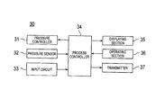
- Fig. 2 is a schematic block diagram exemplifying the configuration of a measurement apparatus illustrated in Fig. 1.
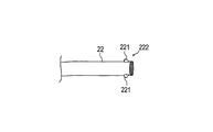
- Fig. 3A is a diagrammatic view exemplifying the structure of a first tube illustrated in Fig. 1.
- Fig. 3B is a diagrammatic view exemplifying the structure of the first tube illustrated in Fig. 1.
- Fig. 4 is an enlarged sectional view of the broken-line portion A in Fig. 1.
- Fig. 5 is a flowchart describing an example of blood pressure measurement in which the medical measurement system of the first embodiment is used.
- Fig. 6 is a diagrammatic view describing selection of the cuff and probe illustrated in Fig.
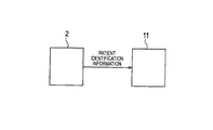
- Fig. 7 is a conceptual view describing writing of patient identification information in the probe.
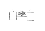
- Fig. 8 is a conceptual view describing provision of blood pressure data to a medical person.
- Fig. 9 is a block diagram schematically illustrating the configuration of a medical measurement system of a second embodiment.
- Fig. 10 is a flowchart exemplifying a process procedure of a blood pressure measurement by the medical measurement system of the second embodiment.
- Fig. 1 is a block diagram schematically illustrating the configuration of a medical measurement system of a first embodiment
- Fig. 2 is a schematic block diagram exemplifying the configuration of a measurement apparatus illustrated in Fig. 1.
- the medical measurement system 1 can include a detection unit 10, a cuff unit 20, and the measurement apparatus (medical measurement apparatus) 30.
- a combination of the detection unit 10 and the cuff unit 20 constitutes a sensor unit 40.
- the detection unit 10 can include a probe 11 and a signal cable 12.
- the probe 11 can include a detector 111 and a memory 112.
- the detector 111 detects a pulse wave which is a vital signs signal of the patient.
- the probe 11 is an SpO 2 probe for measuring the arterial oxygen saturation, and to be attached to the finger of the hand of the patient to acquire the peripheral pulse wave (hereinafter, referred to as "first pulse wave") from pulse wave components relating to the light absorption of the blood.
- the memory 112 stores patient identification information.
- the patient identification information contains information for identifying the patient, such as the name and date of birth of the patient, and the serial number of the patient chart registered in a hospital. In the measurement apparatus 30, updating of the patient identification information is inhibited, and the patient identification information is allowed to be written only once in the memory 112.
- the memory 112 can store also blood pressure data, vital signs information (for example, the first pulse wave), and the like of the patient which are acquired by the measurement apparatus 30.
- vital signs information for example, the first pulse wave
- the signal cable 12 is a cable which functions as the first connecting portion, and which electrically connects the probe 11 and the measurement apparatus 30 to each other, and transmits the vital signs signal detected by the detector 111 to the measurement apparatus 30. Moreover, the patient identification information, and blood pressure data and vital signs information of the patient which are acquired by the measurement apparatus 30 can be transmitted to the memory 112 through the signal cable 12. One end of the signal cable 12 is connected and fixed to the probe 11, and the other end of the signal cable 12 is connected to the measurement apparatus 30.
- the cuff unit 20 can include a cuff 21, a first tube 22, a second tube 23, and a relay 24.
- the cuff 21 is a bag-like belt which is to be wrapped around the upper arm in the vicinity of the axillary cavity of the patient to be attached thereto.
- the cuff 21 is supplied with air from the measurement apparatus 30, compresses the upper arm of the patient, and detects a pulse wave (hereinafter, referred to as "second pulse wave”) which is vibration of the blood vessel wall, from the belt, and transmits the pulse wave to the measurement apparatus 30.
- second pulse wave a pulse wave
- the first tube 22 and the second tube 23 are tubes (hollow tubes) which function as the second connecting portion, and through which the air supplied from the measurement apparatus 30 is sent to the cuff 21.
- One end of the first tube 22 is connected and fixed to the cuff 21, and the other end is connected in the relay 24 to one end of the second tube 23.
- the other end of the second tube 23 is connected to the measurement apparatus 30.
- the relay 24 is fixed to the signal cable 12 at a predetermined position which is between the probe 11 and the measurement apparatus 30.
- the measurement apparatus 30 is a venous pressure measurement apparatus, acquires the first and second pulse waves of the patient, and measures the central venous pressure of the patient based on the first and second pulse waves.
- the measurement apparatus 30 can include a pressure controller 31, a pressure sensor 32, an input circuit 33, a process controller 34, a displaying section 35, an operating section 36, and a transmitter 37.
- the pressure controller 31 supplies air to the cuff 21 attached to the patient, in accordance with instructions from the process controller 34.
- the pressure controller 31 controls the amount of the air which is to be supplied to the cuff 21, thereby adjusting the degree of inflation of the cuff 21.
- the pressure sensor 32 receives the second pulse wave from the cuff 21, converts the second pulse wave to an electric signal, and supplies the electric signal to the process controller 34.
- the pressure sensor 32 may be a piezoelectric element which converts a pressure wave that is transmitted by using air as a medium, to an electric signal.
- the input circuit 33 functions as the vital signs information acquiring section, receives an electric signal of the plethysmogram (the first pulse wave) from the probe 11, amplifies the electric signal to a voltage electric signal, and then supplies the voltage electric signal to the process controller 34.
- the process controller 34 controls the pressure controller 31, the displaying section 35, and the transmitter 37.
- the process controller 34 functions as the blood pressure measuring section, receives first and second pulse wave signals respectively from the input circuit 33 and the pressure sensor 32, and calculates the central venous pressure (blood pressure) of the patient based on the first and second pulse wave signals, by using the principle of the oscillometric method. Namely, the process controller 34 measures the blood pressure of the patient based on the first pulse wave signal transmitted from the probe 11, and the second pulse wave signal (vibration) transmitted from the cuff unit 20.
- the process controller 34 functions also as the vital signs information acquiring section, and acquires vital signs information of the patient based on the first pulse wave signal.
- the displaying section 35 can include, for example, a liquid crystal display, and displays various waveforms, calculation results, messages, and the like which are received from the process controller 34.
- the operating section 36 can include, for example, a power supply switch, a measurement start button, a touch panel for inputting the patient identification information and the like, a switch for selecting the mode, etc., and supplies instructions from the user to the process controller 34.
- the transmitter 37 transmits transmission data containing the patient identification information and the blood pressure data to an information terminal of the medical person.
- the transmission data may contain the vital signs information.
- the transmitter 37 can include an encryption module which is not illustrated, encrypts the transmission data by using an encryption key contained in the patient identification information, and transmits the encrypted transmission data to the information terminal of the medical person. Since the transmission data are encrypted, it is possible to ensure the confidentiality of the transmission data.
- the other configuration of the measurement apparatus 30 is identical with the configuration of a conventional venous pressure measurement apparatus, and therefore its detailed description will be omitted.
- Figs. 3A and 3A are diagrammatic views exemplifying the structure of the first tube 22 illustrated in Fig. 1, and Fig. 4 is an enlarged sectional view of the broken-line portion A in Fig. 1.
- another end portion 222 of the first tube 22 which is to be joined to the second tube 23 is threaded.
- the other end portion 222 is screwed with the relay 24 at a position where the other end portion is to be joined to the one end of the second tube 23, or namely the other end portion 222 is coupled with the relay 24 by rotating the other end portion along the thread.
- the first tube 22 can include at least one engagement member 221 in the other end portion 222.
- Figs. 3A and 3B exemplarily illustrate a case where the first tube 22 includes two engagement members 221.
- the engagement members 221 are fitted into recesses of the side surface of the first tube 22, and urged by spring members disposed in the recesses so as to project toward the outside of the side surface of the first tube 22, respectively (see Fig. 4).
- Each of engagement members 221 can include a taper portion in the side where the member is to be joined to the second tube 23.
- the side opposite to the taper portion is formed to be substantially perpendicular to the central axis of the first tube 22. Because of the structure, when the other end portion 222 is inserted into the relay 24, the taper portion is in contact with an insertion opening of the relay 24, and, in accordance with the advancement of the other end portion 222 in the relay 24, the forces in the directions of the hollow arrows act on the engagement members 221.
- the sides opposite to the taper portions are formed to be substantially perpendicular to the central axis of the first tube 22.
- the engagement members 221 project respectively into the recesses of the relay 24, therefore, the movement in the direction in which the other end portion 222 is pulled out from the relay 24 is blocked.
- the other end portion 222 once advances to the joined position in the relay 24, namely, the other end portion 222 is locked in the relay 24, and the first tube 22 cannot be pulled out from the relay 24. Therefore, the cuff unit 20 is fixed to the detection unit 10, or namely the detection unit 10 and the cuff unit 20 are fixed to each other, and the two units become inseparable from each other. Consequently, the cuff unit 20 and the detection unit 10 can be prevented from being erroneously separated from each other by the patient.
- the structure for fixing the cuff unit 20 to the detection unit 10 is not limited to the above-described structure. Any structure may be employed so far as it is configured so that, when the cuff unit 20 is once fixed to the detection unit 10, the units cannot be separated from each other, or the separation involves breakage.
- a configuration may be employed where a first fixing portion is disposed in an intermediate portion of the signal cable connecting the probe and the measurement apparatus, a second fixing portion is disposed in an intermediate portion of the tube connecting the cuff and the measurement apparatus, and the first and second fixing portions are inseparably fixed.
- Fig. 5 is a flowchart describing an example of a blood pressure measurement in which the medical measurement system 1 of the embodiment is used
- Fig. 6 is a diagrammatic view describing selection of the cuff and the probe, and the configuration of the sensor unit
- Fig. 7 is a conceptual view describing writing of the patient identification information in the probe
- Fig. 8 is a conceptual view describing provision of the blood pressure data to the medical person.
- the medical person selects a cuff and probe which are appropriate for the patient (step S101).
- the medical person prepares a plurality of cuffs and probes having different sizes so as to cope with a plurality of patients with different physical sizes, and selects an appropriate cuff and probe which are suitable for the physical size of the patient P whose blood pressure is to be measured.
- the blood pressure is measured by using the appropriate cuff and probe which are suitable for the physical size of the patient P, the blood pressure of the patient P is correctly obtained.
- cuffs C1 to Cn and probes P1 to Pn having different sizes are prepared with respect to the cuff 21 and the probe 11, respectively, and then stored in the vicinity of the medical person in a state where, in each of the relays 24, the first tube 22 and the second tube 23 are not joined to each other.
- the medical person integrates the detection unit 10 with the cuff unit 20 to configure the sensor unit 40 (step S102).
- the medical person joins the first tube 22 of the selected cuff 21 to the second tube 23 in the relay 24 attached to the selected probe 11, thereby configuring the sensor unit 40 in which the detection unit 10 and the cuff unit 20 are integrated with each other.
- the sensor unit 40 which is configured in accordance with the physical size of the patient P is allowed to be used only by the patient P.
- patients other than the patient P are not allowed to use the thus configured sensor unit 40. Since patients other than the patient P are disabled to use the sensor unit 40 as described above, it is possible to prevent an infection from spreading among patients.
- the medical person writes the patient identification information in the probe 11 (step S103).
- the medical person writes the patient identification information of the patient P in the memory 112 of the probe 11 by using the information terminal 2 such as a personal computer, or the measurement apparatus 30.
- the patient identification information is input through, for example, a touch panel of the operating section 36.
- the patient P measures the blood pressure by using the medical measurement system 1 (step S104).
- the patient P measures the blood pressure in a place where the blood pressure can be periodically measured in the resting state, such as the home of the patient.
- the measurement is conducted in the following procedure. (1)
- the sensor unit 40 is connected to the measurement apparatus 30.
- the measurement apparatus 30 is powered on.
- the cuff 21 of the sensor unit 40 is attached to the upper arm, and the probe 11 is attached to the fingertip.
- the operating section 36 is operated to start the measurement (the measurement start button is pressed). (5) A result of the measurement is checked.
- the cuff 21 may be attached to either of the right and left arms.
- the finger to which the probe 11 is attached may be a finger of either of the right and left hands.
- the probe 11 may be attached to a finger of the hand on the same side as the arm to which the cuff 21 is attached.
- the process controller 34 controls the pressure controller 31 to inflate the cuff 21 attached to the patient P, and calculates the blood pressure (central venous pressure) of the patient based on the electric signal of the first pulse wave supplied from the input circuit 33, and that of the second pulse wave supplied from the pressure sensor 32. Moreover, the process controller 34 causes the value of the calculated blood pressure to be displayed on the displaying section 35.
- a configuration may be employed where, in the case where the state of the first pulse wave of the patient P is stable, the measurement of the blood pressure of the patient P is allowed.
- the parameters may contain, for example, the pulse wave amplitude and the pulse wave interval.
- the patient P provides the medical person with the measured blood pressure data (step S105).
- the patient P operates the operating section 36 so as to transmit the measured blood pressure data from the medical measurement system 1 to the information terminal 2 of the medical person.
- the transmitter 37 may encrypt the transmission data containing the patient identification information and blood pressure data of the patient P may be encrypted, and the encrypted data may be automatically transmitted through a wireless communication to the information terminal 2 which is in a remote place. According to the configuration, the medical person can surely acquire the blood pressure data of the patient P.
- the patient identification information and the blood pressure data may be stored in the memory 112, and the patient P oneself may directly bring the medical measurement system 1 or the sensor unit 40 into a medical facility where the medical person stays.
- a configuration may be employed where, in an area where a radio wave is hardly transmitted and received, such as a mountain area, the transmission data are transmitted by using a wired network communication, a telephone line, or the like.
- the medical person checks the blood pressure data of the patient P (step S106).
- the information terminal 2 receives the encrypted transmission data, and decrypts the transmission data by using the encryption key which is stored in the information terminal 2, and which is a key for the patient identification information of the patient P.
- the medical person operates the information terminal 2 to collate the patient identification information of the acquired transmission data with the patient identification information of the patient P stored in the information terminal 2, thereby confirming that the transmission data are data of the patient P.
- the medical person checks the blood pressure data of the patient P.
- the cuff 21 and probe 11 which are suitable for the physical size of the patient P are selected by the medical person, the cuff unit 20 including the cuff 21 is fixed to the detection unit including the probe 11. Moreover, the patient identification information of the patient P is written in the memory 112 of the probe 11 by the medical person.
- the sensor unit 40 and medical measurement system 1 of the thus configured embodiment achieve the following effects.
- the cuff unit 20 including the cuff 21 is fixed to the detection unit 10 including the probe 11.
- the patient P can remember the presence of the probe. Consequently, it is possible to prevent or suppress the patient P from, when the patient is to use the medical measurement system 1, forgetting the attachment of the probe 11, and hence it is possible to prevent or suppress the blood pressure measurement from being performed in a state where the probe 11 is not attached to the patient P.
- the probe 11 includes the memory 112 which stores the patient identification information of the patient P. As far as only the patient P uses the sensor unit 40 to measure the blood pressure, it is ensured that the first pulse wave supplied from the probe 11, and the second pulse wave supplied from the cuff 21 are acquired from the patient P.
- Fig. 9 is a block diagram schematically illustrating the configuration of the medical measurement system of the second embodiment
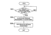
- Fig. 10 is a flowchart exemplifying a process procedure of the blood pressure measurement by the medical measurement system of the second embodiment.
- the medical measurement system 3 can include a detection unit 50, a cuff unit 60, and a measurement apparatus 70.
- a combination of the detection unit 50 and the cuff unit 60 constitutes a sensor unit 80.
- the detection unit 50 can include a probe 51 and a signal cable 52.
- the probe 51 can include a detector 511.
- the signal cable 52 is a cable which functions as the first connecting portion, and which electrically connects the probe 51 and the measurement apparatus 70 to each other.
- the probe 51 is an SpO 2 probe for measuring the arterial oxygen saturation.
- the cuff unit 60 can include a cuff 61 and a tube 62.
- the tube 62 is a tube (hollow tube) which functions as the second connecting portion, and through which the air supplied from the measurement apparatus 70 is sent to the cuff 61.
- One end of the tube 62 is connected and fixed to the cuff 61, and the other end is connected to the measurement apparatus 70.
- the measurement apparatus 70 determines whether the state of the vital signs signal supplied from the probe 51 is stable or not (step S201).
- the determination whether the state of the vital signs signal is stable or not is performed by considering whether the parameters of the pulse wave of the patient P are within the respective normal ranges or not.
- the parameters may contain, for example, the pulse wave amplitude and the pulse wave interval.
- step S201 If the state of the vital signs signal supplied from the probe 51 is not stable (step S201: NO), the process waits until the vital signs signal supplied from the probe 51 becomes stable. In the case where it is immediately after the patient P exercises vigorously, for example, the heart rate is high, and the condition of the patient is not suitable for the blood pressure measurement. Therefore, the measurement apparatus 70 waits until the variation of the heart rate falls below a predetermined value (range).
- the measurement apparatus 70 cannot detect the vital signs signal supplied from the probe 51.
- the measurement apparatus 70 causes a message indicating that the probe is not attached, such as "Probe is not attached.” to be displayed on the displaying section, and waits until the probe is attached.
- the measurement apparatus 70 allows the blood pressure measurement to be performed (step S202).
- the measurement apparatus 70 causes a message indicating that the blood pressure measurement can be started, to be displayed on the displaying section, and receives instructions for starting the measurement from the patient P.
- the patient P presses the measurement start button.
- the measurement apparatus 70 calculates the blood pressure (central venous pressure) of the patient based on the first pulse wave supplied from the probe 51, and the second pulse wave supplied from the cuff 61.
- the sensor unit 80 and medical measurement system 3 of the embodiment which has been described above achieve the following effects.
- the measurement apparatus 70 allows the patient to perform the blood pressure measurement. Therefore, it is possible to prevent or suppress the blood pressure measurement from being performed in a state where the probe 51 is not attached to the patient.
- the effect can be achieved irrespective of whether the cuff unit 60 is inseparably fixed to the detection unit 50 or not.
- the medical measurement system may have a structure where, when the end portion of the tube 62 of the cuff unit 60 is once attached to the measurement apparatus 70, the tube cannot be detached from the apparatus.
- the cuff unit 60 may be fixed to the detection unit 50 through the measurement apparatus 70.
- the second embodiment can achieve the same effect as the first embodiment.
- an SpO 2 probe is used as the probe.
- the present invention is not limited to the case.
- a probe for a photoplethysmograph or electrodes for an electrocardiogram may be used, so that a pulse wave supplied from the cuff attached to the patient, and a vital signs signal supplied from the detector can be used simultaneously and surely.
- the probe includes a memory
- the cuff does not handle an electrical signal. If the cuff is requested to include a memory, therefore, new components are additionally required, and the production cost of the resulting cuff is more expensive as compared with that of a usual cuff.
- the prove handles an electrical signal, and therefore can easily include a memory.
- the present invention is not limited to the case, and the memory may be placed in a place in the detection unit other than the probe, or the relay.
- the cuff unit has the structure in which, when the cuff unit is once fixed to the detection unit, the cuff unit cannot be separated from the detection unit has been described.
- the present invention is not limited to the case.
- a structure may be employed in which the patient measures the blood pressure in a state where the cuff unit is fixed to the detection unit, and, after the measurement, the medical person can separate the cuff unit and the detection unit from each other.
- a medical measurement system which prevents or suppress a blood pressure measurement from being performed in a state where a probe is not attached to the patient.
Landscapes
- Health & Medical Sciences (AREA)
- Life Sciences & Earth Sciences (AREA)
- Cardiology (AREA)
- Vascular Medicine (AREA)
- Physiology (AREA)
- Medical Informatics (AREA)
- Surgery (AREA)
- Biophysics (AREA)
- Pathology (AREA)
- Engineering & Computer Science (AREA)
- Biomedical Technology (AREA)
- Heart & Thoracic Surgery (AREA)
- Veterinary Medicine (AREA)
- Molecular Biology (AREA)
- Physics & Mathematics (AREA)
- Animal Behavior & Ethology (AREA)
- General Health & Medical Sciences (AREA)
- Public Health (AREA)
- Ophthalmology & Optometry (AREA)
- Dentistry (AREA)
- Pulmonology (AREA)
- Measuring Pulse, Heart Rate, Blood Pressure Or Blood Flow (AREA)
- Measurement Of The Respiration, Hearing Ability, Form, And Blood Characteristics Of Living Organisms (AREA)
- Measuring And Recording Apparatus For Diagnosis (AREA)
- Measurement And Recording Of Electrical Phenomena And Electrical Characteristics Of The Living Body (AREA)
Abstract
A sensor unit which is to be connected to a medical measurement apparatus includes a detection unit that includes a detector which detects a vital signs signal of a patient and a first connecting portion which connects the detector and the medical measurement apparatus to each other and a cuff unit that includes a cuff which is to be attached to the patient and a second connecting portion which connects the cuff and the medical measurement apparatus to each other through a hollow tube. In the sensor unit, the detection unit or the cuff unit includes a memory which stores identification information for identifying the patient, and the detection unit and the cuff unit are fixed to each other.
Description
The present invention relates to a sensor unit and a medical measurement system.
In order to reduce the burden on the patient, a medical measurement system for noninvasively acquiring vital signs information of the patient is under development. For example, Japanese Patent No. 5,694,032 discloses a venous pressure measurement apparatus which uses the oscillometric method to noninvasively measure the central venous pressure (CVP). In the apparatus disclosed in Japanese Patent No. 5,694,032, a cuff which is attached to the upper arm of the patient by a medical person such as a doctor, and a probe which is attached to the finger are used, and a pulse wave in a site distal from the heart, and that in a site proximal to the heart are simultaneously measured, and the central venous pressure is calculated based on a correlation between the pulse waves.
In recent years, with miniaturization and sophistication of medical measurement systems, opportunities in which the patient acquires own vital signs information by using a medical measurement system in a place other than a hospital, such as the home of the patient are increasing. In the case where the patient uses a medical measurement system in a place such as the home of the patient, unlike a measurement in a hospital, the patient oneself must attach a cuff and a probe to respective predetermined sites, and then operate the medical measurement system. In the case of the above-described venous pressure measurement apparatus, for example, the patient oneself is requested to attach the cuff and the probe to the upper arm and the finger, respectively, and then starts the measurement.
In the case where the patient uses a medical measurement system in a place other than a hospital, there is a possibility that the patient forgets to attach the probe, and the blood pressure is measured in a state where the probe is not attached to the patient since the medical person hardly checks the attachment in a place other than a hospital.
When the blood pressure is measured in a state where the probe is not attached to the patient, the blood pressure of the patient is not correctly measured.
The present invention has been conducted in order to solve the above problem. Therefore, it is an object of the present invention to provide a sensor unit in which it is possible to prevent or suppress a measurement from being performed in a state where a probe is not attached to the patient, and a medical measurement system having the sensor unit.
The object of the present invention is attained by the following configurations.
A sensor unit has a cuff unit and a detection unit, and is to be connected to a medical measurement apparatus. The detection unit has a detector and a first connecting portion. The detector detects a vital signs signal of a patient. The first connecting portion is to connect the detector and the medical measurement apparatus to each other. The cuff unit has a cuff and a second connecting portion. The cuff is to be attached to the patient. The second connecting portion is to connect the cuff and the medical measurement apparatus to each other through a hollow tube. The detection unit or the cuff unit has a memory. The memory stores identification information for identifying the patient. The detection unit and the cuff unit are fixed to each other.
A medical measurement system has a medical measurement apparatus and a sensor unit which is connected to the medical measurement apparatus. The sensor unit has a detection unit and a cuff unit. The detection unit has a detector and a first connecting portion. The detector detects a vital signs signal of a patient. The first connecting portion connects the detector and the medical measurement apparatus to each other. The cuff unit has a cuff and a second connecting portion. The cuff is to be attached to the patient. The second connecting portion connects the cuff and the medical measurement apparatus to each other through a hollow tube. The detection unit or the cuff unit has a memory. The memory stores identification information for identifying the patient. The detection unit and the cuff unit are fixed to each other. The medical measurement apparatus has a blood pressure measuring section, a vital signs information acquiring section, and a transmitter. The blood pressure measuring section measures a blood pressure of the patient based on vibration transmitted from the cuff unit. The vital signs information acquiring section acquires vital signs information of the patient based on the vital signs signal detected by the detector. The transmitter transmits transmission data containing the identification information, data of the blood pressure, and vital signs information of the patient.
Another medical measurement system has a medical measurement apparatus and a sensor unit which is connected to the medical measurement apparatus. The sensor unit has a detection unit and a cuff unit. The detection unit has a detector and a first connecting portion. The detector detects a vital signs signal of a patient. The first connecting portion connects the detector and the medical measurement apparatus to each other. The cuff unit has a cuff and a second connecting portion. The cuff is to be attached to the patient. The second connecting portion connects the cuff and the medical measurement apparatus to each other through a hollow tube. The medical measurement apparatus has a blood pressure measuring section and a vital signs information acquiring section. The blood pressure measuring section measures a blood pressure of the patient based on vibration transmitted from the cuff unit. The vital signs information acquiring section acquires vital signs information of the patient based on the vital signs signal detected by the detector. In the case where a state of the vital signs signal of the patient which is detected by the detector is stable, the blood pressure measuring section allows the blood pressure of the patient to be measured.
In the case where the detection unit having the probe, and the cuff unit having the cuff are fixed to each other, or the state of the vital signs signal of the patient which is detected by the probe is stable, the blood pressure measuring section allows the blood pressure of the patient to be measured. Therefore, it is possible to prevent or suppress the blood pressure measurement from being performed in a state where the probe is not attached to the patient.
Hereinafter, embodiments of the sensor unit and medical measurement system of the present invention will be described with reference to the accompanying drawings. In the figures, the identical components are denoted by the same reference numerals. In the drawings, the dimension ratios are exaggerated for the sake of convenience in description, and may be sometimes different from the actual ratios.
(First embodiment)
<Medical measurement system 1>
Fig. 1 is a block diagram schematically illustrating the configuration of a medical measurement system of a first embodiment, and Fig. 2 is a schematic block diagram exemplifying the configuration of a measurement apparatus illustrated in Fig. 1. As illustrated in Fig. 1, themedical measurement system 1 can include a detection unit 10, a cuff unit 20, and the measurement apparatus (medical measurement apparatus) 30. A combination of the detection unit 10 and the cuff unit 20 constitutes a sensor unit 40.
<
Fig. 1 is a block diagram schematically illustrating the configuration of a medical measurement system of a first embodiment, and Fig. 2 is a schematic block diagram exemplifying the configuration of a measurement apparatus illustrated in Fig. 1. As illustrated in Fig. 1, the
The detection unit 10 can include a probe 11 and a signal cable 12. The probe 11 can include a detector 111 and a memory 112.
The detector 111 detects a pulse wave which is a vital signs signal of the patient. For example, the probe 11 is an SpO2 probe for measuring the arterial oxygen saturation, and to be attached to the finger of the hand of the patient to acquire the peripheral pulse wave (hereinafter, referred to as "first pulse wave") from pulse wave components relating to the light absorption of the blood.
The memory 112 stores patient identification information. The patient identification information contains information for identifying the patient, such as the name and date of birth of the patient, and the serial number of the patient chart registered in a hospital. In the measurement apparatus 30, updating of the patient identification information is inhibited, and the patient identification information is allowed to be written only once in the memory 112. When the patient identification information of a patient P is once written in the memory 112, therefore, the patient identification information of another patient Q is not written in the memory 112, and measurement data of Patients P and Q are prevented from being confused. The memory 112 can store also blood pressure data, vital signs information (for example, the first pulse wave), and the like of the patient which are acquired by the measurement apparatus 30. In the following description, for the sake of convenience, various kinds of physiological/anatomical information generated by the living body, other than the blood pressure are referred to as "vital signs information."
The signal cable 12 is a cable which functions as the first connecting portion, and which electrically connects the probe 11 and the measurement apparatus 30 to each other, and transmits the vital signs signal detected by the detector 111 to the measurement apparatus 30. Moreover, the patient identification information, and blood pressure data and vital signs information of the patient which are acquired by the measurement apparatus 30 can be transmitted to the memory 112 through the signal cable 12. One end of the signal cable 12 is connected and fixed to the probe 11, and the other end of the signal cable 12 is connected to the measurement apparatus 30.
The cuff unit 20 can include a cuff 21, a first tube 22, a second tube 23, and a relay 24. The cuff 21 is a bag-like belt which is to be wrapped around the upper arm in the vicinity of the axillary cavity of the patient to be attached thereto. The cuff 21 is supplied with air from the measurement apparatus 30, compresses the upper arm of the patient, and detects a pulse wave (hereinafter, referred to as "second pulse wave") which is vibration of the blood vessel wall, from the belt, and transmits the pulse wave to the measurement apparatus 30.
The first tube 22 and the second tube 23 are tubes (hollow tubes) which function as the second connecting portion, and through which the air supplied from the measurement apparatus 30 is sent to the cuff 21. One end of the first tube 22 is connected and fixed to the cuff 21, and the other end is connected in the relay 24 to one end of the second tube 23. On the other hand, the other end of the second tube 23 is connected to the measurement apparatus 30. The relay 24 is fixed to the signal cable 12 at a predetermined position which is between the probe 11 and the measurement apparatus 30.
For example, the measurement apparatus 30 is a venous pressure measurement apparatus, acquires the first and second pulse waves of the patient, and measures the central venous pressure of the patient based on the first and second pulse waves.
As illustrated in Fig. 2, the measurement apparatus 30 can include a pressure controller 31, a pressure sensor 32, an input circuit 33, a process controller 34, a displaying section 35, an operating section 36, and a transmitter 37.
The pressure controller 31 supplies air to the cuff 21 attached to the patient, in accordance with instructions from the process controller 34. The pressure controller 31 controls the amount of the air which is to be supplied to the cuff 21, thereby adjusting the degree of inflation of the cuff 21.
The pressure sensor 32 receives the second pulse wave from the cuff 21, converts the second pulse wave to an electric signal, and supplies the electric signal to the process controller 34. The pressure sensor 32 may be a piezoelectric element which converts a pressure wave that is transmitted by using air as a medium, to an electric signal.
The input circuit 33 functions as the vital signs information acquiring section, receives an electric signal of the plethysmogram (the first pulse wave) from the probe 11, amplifies the electric signal to a voltage electric signal, and then supplies the voltage electric signal to the process controller 34.
The process controller 34 controls the pressure controller 31, the displaying section 35, and the transmitter 37. The process controller 34 functions as the blood pressure measuring section, receives first and second pulse wave signals respectively from the input circuit 33 and the pressure sensor 32, and calculates the central venous pressure (blood pressure) of the patient based on the first and second pulse wave signals, by using the principle of the oscillometric method. Namely, the process controller 34 measures the blood pressure of the patient based on the first pulse wave signal transmitted from the probe 11, and the second pulse wave signal (vibration) transmitted from the cuff unit 20. An algorithm for measuring the central venous pressure based on the first pulse wave in a site distal from the heart, and the second pulse wave in a site proximal to the heart is known, and therefore its detailed description will be omitted. The process controller 34 functions also as the vital signs information acquiring section, and acquires vital signs information of the patient based on the first pulse wave signal.
The displaying section 35 can include, for example, a liquid crystal display, and displays various waveforms, calculation results, messages, and the like which are received from the process controller 34.
The operating section 36 can include, for example, a power supply switch, a measurement start button, a touch panel for inputting the patient identification information and the like, a switch for selecting the mode, etc., and supplies instructions from the user to the process controller 34.
The transmitter 37 transmits transmission data containing the patient identification information and the blood pressure data to an information terminal of the medical person. The transmission data may contain the vital signs information. The transmitter 37 can include an encryption module which is not illustrated, encrypts the transmission data by using an encryption key contained in the patient identification information, and transmits the encrypted transmission data to the information terminal of the medical person. Since the transmission data are encrypted, it is possible to ensure the confidentiality of the transmission data.
The other configuration of the measurement apparatus 30 is identical with the configuration of a conventional venous pressure measurement apparatus, and therefore its detailed description will be omitted.
<Sensor unit 40>
Next, thesensor unit 40 in the embodiment will be described in detail with reference to Figs. 3A, 3B, and 4. Figs. 3A and 3A are diagrammatic views exemplifying the structure of the first tube 22 illustrated in Fig. 1, and Fig. 4 is an enlarged sectional view of the broken-line portion A in Fig. 1.
Next, the
As illustrated in Fig. 3A, another end portion 222 of the first tube 22 which is to be joined to the second tube 23 is threaded. The other end portion 222 is screwed with the relay 24 at a position where the other end portion is to be joined to the one end of the second tube 23, or namely the other end portion 222 is coupled with the relay 24 by rotating the other end portion along the thread.
The first tube 22 can include at least one engagement member 221 in the other end portion 222. Figs. 3A and 3B exemplarily illustrate a case where the first tube 22 includes two engagement members 221. The engagement members 221 are fitted into recesses of the side surface of the first tube 22, and urged by spring members disposed in the recesses so as to project toward the outside of the side surface of the first tube 22, respectively (see Fig. 4).
When forces (forces in the directions of the hollow arrows) directed from the periphery of the first tube 22 toward the central axis are applied against the forces of the spring members, as illustrated in Fig. 3B, the engagement members 221 sink into the recesses of the side surface of the first tube 22, respectively.
Each of engagement members 221 can include a taper portion in the side where the member is to be joined to the second tube 23. In the engagement member 221, the side opposite to the taper portion is formed to be substantially perpendicular to the central axis of the first tube 22. Because of the structure, when the other end portion 222 is inserted into the relay 24, the taper portion is in contact with an insertion opening of the relay 24, and, in accordance with the advancement of the other end portion 222 in the relay 24, the forces in the directions of the hollow arrows act on the engagement members 221.
When the other end portion is further rotationally inserted into the relay 24 so as be screwed with the relay 24, the engagement members 221 are pressingly inserted into the recesses to sink therein, respectively, and the other end portion 222 can advance to the joined position where the other end portion is to be joined to the one end of the second tube 23.
As illustrated in Fig. 4, at the timing when the other end portion 222 advances to the joined position, the engagement members 221 are released from the forces in the directions of the hollow arrows due to the insertion opening, and therefore caused by the forces of the spring members to project into the recesses, respectively.
In the engagement members 221, by contrast, the sides opposite to the taper portions are formed to be substantially perpendicular to the central axis of the first tube 22. When the engagement members 221 project respectively into the recesses of the relay 24, therefore, the movement in the direction in which the other end portion 222 is pulled out from the relay 24 is blocked. When the other end portion 222 once advances to the joined position in the relay 24, namely, the other end portion 222 is locked in the relay 24, and the first tube 22 cannot be pulled out from the relay 24. Therefore, the cuff unit 20 is fixed to the detection unit 10, or namely the detection unit 10 and the cuff unit 20 are fixed to each other, and the two units become inseparable from each other. Consequently, the cuff unit 20 and the detection unit 10 can be prevented from being erroneously separated from each other by the patient.
The structure for fixing the cuff unit 20 to the detection unit 10 is not limited to the above-described structure. Any structure may be employed so far as it is configured so that, when the cuff unit 20 is once fixed to the detection unit 10, the units cannot be separated from each other, or the separation involves breakage.
For example, a configuration may be employed where a first fixing portion is disposed in an intermediate portion of the signal cable connecting the probe and the measurement apparatus, a second fixing portion is disposed in an intermediate portion of the tube connecting the cuff and the measurement apparatus, and the first and second fixing portions are inseparably fixed.
<Example of blood pressure measurement in which medical measurement system 1 is used>
Fig. 5 is a flowchart describing an example of a blood pressure measurement in which themedical measurement system 1 of the embodiment is used, Fig. 6 is a diagrammatic view describing selection of the cuff and the probe, and the configuration of the sensor unit, Fig. 7 is a conceptual view describing writing of the patient identification information in the probe, and Fig. 8 is a conceptual view describing provision of the blood pressure data to the medical person.
Fig. 5 is a flowchart describing an example of a blood pressure measurement in which the
As illustrated in Fig. 5, firstly, the medical person selects a cuff and probe which are appropriate for the patient (step S101). In the example, the medical person prepares a plurality of cuffs and probes having different sizes so as to cope with a plurality of patients with different physical sizes, and selects an appropriate cuff and probe which are suitable for the physical size of the patient P whose blood pressure is to be measured. When the blood pressure is measured by using the appropriate cuff and probe which are suitable for the physical size of the patient P, the blood pressure of the patient P is correctly obtained.
As illustrated in Fig. 6, for example, cuffs C1 to Cn and probes P1 to Pn having different sizes are prepared with respect to the cuff 21 and the probe 11, respectively, and then stored in the vicinity of the medical person in a state where, in each of the relays 24, the first tube 22 and the second tube 23 are not joined to each other.
Next, the medical person integrates the detection unit 10 with the cuff unit 20 to configure the sensor unit 40 (step S102). The medical person joins the first tube 22 of the selected cuff 21 to the second tube 23 in the relay 24 attached to the selected probe 11, thereby configuring the sensor unit 40 in which the detection unit 10 and the cuff unit 20 are integrated with each other. The sensor unit 40 which is configured in accordance with the physical size of the patient P is allowed to be used only by the patient P. On the other hand, patients other than the patient P are not allowed to use the thus configured sensor unit 40. Since patients other than the patient P are disabled to use the sensor unit 40 as described above, it is possible to prevent an infection from spreading among patients.
Next, the medical person writes the patient identification information in the probe 11 (step S103). As illustrated in Fig. 7, the medical person writes the patient identification information of the patient P in the memory 112 of the probe 11 by using the information terminal 2 such as a personal computer, or the measurement apparatus 30. In the case where the writing is performed by using the measurement apparatus 30, the patient identification information is input through, for example, a touch panel of the operating section 36.
Next, the patient P measures the blood pressure by using the medical measurement system 1 (step S104). The patient P measures the blood pressure in a place where the blood pressure can be periodically measured in the resting state, such as the home of the patient. The measurement is conducted in the following procedure. (1) The sensor unit 40 is connected to the measurement apparatus 30. (2) The measurement apparatus 30 is powered on. (3) The cuff 21 of the sensor unit 40 is attached to the upper arm, and the probe 11 is attached to the fingertip. (4) The operating section 36 is operated to start the measurement (the measurement start button is pressed). (5) A result of the measurement is checked.
The cuff 21 may be attached to either of the right and left arms. The finger to which the probe 11 is attached may be a finger of either of the right and left hands. Preferably, the probe 11 may be attached to a finger of the hand on the same side as the arm to which the cuff 21 is attached.
The process controller 34 controls the pressure controller 31 to inflate the cuff 21 attached to the patient P, and calculates the blood pressure (central venous pressure) of the patient based on the electric signal of the first pulse wave supplied from the input circuit 33, and that of the second pulse wave supplied from the pressure sensor 32. Moreover, the process controller 34 causes the value of the calculated blood pressure to be displayed on the displaying section 35.
Alternatively, a configuration may be employed where, in the case where the state of the first pulse wave of the patient P is stable, the measurement of the blood pressure of the patient P is allowed. By considering whether parameters of the first pulse wave are within the respective normal ranges or not, it is determined whether the state of the first pulse wave is stable or not. The parameters may contain, for example, the pulse wave amplitude and the pulse wave interval. When the measurement of the blood pressure of the patient P is allowed in the case where the state of the first pulse wave of the patient P is stable, the value of the blood pressure of the patient P can be correctly acquired.
Next, the patient P provides the medical person with the measured blood pressure data (step S105). As illustrated in Fig. 8, the patient P operates the operating section 36 so as to transmit the measured blood pressure data from the medical measurement system 1 to the information terminal 2 of the medical person. After the blood pressure measurement by the measurement apparatus 30 is ended, moreover, the transmitter 37 may encrypt the transmission data containing the patient identification information and blood pressure data of the patient P may be encrypted, and the encrypted data may be automatically transmitted through a wireless communication to the information terminal 2 which is in a remote place. According to the configuration, the medical person can surely acquire the blood pressure data of the patient P.
Alternatively, the patient identification information and the blood pressure data may be stored in the memory 112, and the patient P oneself may directly bring the medical measurement system 1 or the sensor unit 40 into a medical facility where the medical person stays. Alternatively, a configuration may be employed where, in an area where a radio wave is hardly transmitted and received, such as a mountain area, the transmission data are transmitted by using a wired network communication, a telephone line, or the like.
Next, the medical person checks the blood pressure data of the patient P (step S106). The information terminal 2 receives the encrypted transmission data, and decrypts the transmission data by using the encryption key which is stored in the information terminal 2, and which is a key for the patient identification information of the patient P. The medical person operates the information terminal 2 to collate the patient identification information of the acquired transmission data with the patient identification information of the patient P stored in the information terminal 2, thereby confirming that the transmission data are data of the patient P. After it is confirmed that the transmission data are data of the patient P, the medical person checks the blood pressure data of the patient P.
In the blood pressure measurement using the medical measurement system 1 of the embodiment, as described above, the cuff 21 and probe 11 which are suitable for the physical size of the patient P are selected by the medical person, the cuff unit 20 including the cuff 21 is fixed to the detection unit including the probe 11. Moreover, the patient identification information of the patient P is written in the memory 112 of the probe 11 by the medical person. The sensor unit 40 and medical measurement system 1 of the thus configured embodiment achieve the following effects.
The cuff unit 20 including the cuff 21 is fixed to the detection unit 10 including the probe 11. When the patient P is to use the medical measurement system 1, therefore, the patient P can remember the presence of the probe. Consequently, it is possible to prevent or suppress the patient P from, when the patient is to use the medical measurement system 1, forgetting the attachment of the probe 11, and hence it is possible to prevent or suppress the blood pressure measurement from being performed in a state where the probe 11 is not attached to the patient P.
Moreover, the probe 11 includes the memory 112 which stores the patient identification information of the patient P. As far as only the patient P uses the sensor unit 40 to measure the blood pressure, it is ensured that the first pulse wave supplied from the probe 11, and the second pulse wave supplied from the cuff 21 are acquired from the patient P.
(Second embodiment)
The first embodiment in which the cuff unit is fixed to the detection unit, and the patient is caused to remember the existence of the probe has been described. A second embodiment will be described in which a cuff unit is not fixed to a detection unit, and, based on the state of the vital signs signal of the patient, a measurement apparatus determines whether the patient is allowed to measure the blood pressure or not. In the following, with respect to the same configuration as the first embodiment, its detailed description will be omitted in order to avoid duplication of description.
The first embodiment in which the cuff unit is fixed to the detection unit, and the patient is caused to remember the existence of the probe has been described. A second embodiment will be described in which a cuff unit is not fixed to a detection unit, and, based on the state of the vital signs signal of the patient, a measurement apparatus determines whether the patient is allowed to measure the blood pressure or not. In the following, with respect to the same configuration as the first embodiment, its detailed description will be omitted in order to avoid duplication of description.
Fig. 9 is a block diagram schematically illustrating the configuration of the medical measurement system of the second embodiment, and Fig. 10 is a flowchart exemplifying a process procedure of the blood pressure measurement by the medical measurement system of the second embodiment.
As illustrated in Fig. 9, the medical measurement system 3 can include a detection unit 50, a cuff unit 60, and a measurement apparatus 70. A combination of the detection unit 50 and the cuff unit 60 constitutes a sensor unit 80.
The detection unit 50 can include a probe 51 and a signal cable 52. The probe 51 can include a detector 511. The signal cable 52 is a cable which functions as the first connecting portion, and which electrically connects the probe 51 and the measurement apparatus 70 to each other. For example, the probe 51 is an SpO2 probe for measuring the arterial oxygen saturation.
The cuff unit 60 can include a cuff 61 and a tube 62. The tube 62 is a tube (hollow tube) which functions as the second connecting portion, and through which the air supplied from the measurement apparatus 70 is sent to the cuff 61. One end of the tube 62 is connected and fixed to the cuff 61, and the other end is connected to the measurement apparatus 70.
<Process procedure of blood pressure measurement by medical measurement system 3>
The patient P turns on the power supply of themeasurement apparatus 70, and attaches the cuff 61 of the sensor unit 80 to the upper arm, and the probe 51 to the fingertip.
The patient P turns on the power supply of the
As illustrated in Fig. 10, firstly, the measurement apparatus 70 determines whether the state of the vital signs signal supplied from the probe 51 is stable or not (step S201). In the case where the vital signs signal is a pulse wave, the determination whether the state of the vital signs signal is stable or not is performed by considering whether the parameters of the pulse wave of the patient P are within the respective normal ranges or not. The parameters may contain, for example, the pulse wave amplitude and the pulse wave interval.
If the state of the vital signs signal supplied from the probe 51 is not stable (step S201: NO), the process waits until the vital signs signal supplied from the probe 51 becomes stable. In the case where it is immediately after the patient P exercises vigorously, for example, the heart rate is high, and the condition of the patient is not suitable for the blood pressure measurement. Therefore, the measurement apparatus 70 waits until the variation of the heart rate falls below a predetermined value (range).
In the case where the patient P forgets to attach the probe 51 to the finger, and the patient P presses the measurement start button in the state where the probe 51 is not attached to the finger of the patient P, for example, the measurement apparatus 70 cannot detect the vital signs signal supplied from the probe 51. The measurement apparatus 70 causes a message indicating that the probe is not attached, such as "Probe is not attached." to be displayed on the displaying section, and waits until the probe is attached.
If the state of the vital signs signal supplied from the probe 51 is stable (step S201: YES), the measurement apparatus 70 allows the blood pressure measurement to be performed (step S202). The measurement apparatus 70 causes a message indicating that the blood pressure measurement can be started, to be displayed on the displaying section, and receives instructions for starting the measurement from the patient P. The patient P presses the measurement start button.
Next, the blood pressure measurement is performed (step S203). The measurement apparatus 70 calculates the blood pressure (central venous pressure) of the patient based on the first pulse wave supplied from the probe 51, and the second pulse wave supplied from the cuff 61.
The sensor unit 80 and medical measurement system 3 of the embodiment which has been described above achieve the following effects.
In the case where the state of the first pulse wave of the patient which is detected by the probe 51 is stable, the measurement apparatus 70 allows the patient to perform the blood pressure measurement. Therefore, it is possible to prevent or suppress the blood pressure measurement from being performed in a state where the probe 51 is not attached to the patient.
In the second embodiment, the effect can be achieved irrespective of whether the cuff unit 60 is inseparably fixed to the detection unit 50 or not. However, the medical measurement system may have a structure where, when the end portion of the tube 62 of the cuff unit 60 is once attached to the measurement apparatus 70, the tube cannot be detached from the apparatus. Similarly with the first embodiment, that is, the cuff unit 60 may be fixed to the detection unit 50 through the measurement apparatus 70. In this case, also the second embodiment can achieve the same effect as the first embodiment.
Although the sensor unit and medical measurement system of the present invention have been described with reference to the embodiments, it is a matter of course that a person skilled in the art can adequately make additions, modifications, and omissions within the scope of the technical concept of the present invention.
In the above-described first and second embodiments, for example, the case where a cuff which is to be attached to the patient by wrapping the cuff around the upper arm has been described. However, the present invention is not limited to the case, and a cuff which is to be attached to the patient by wrapping the cuff around finger may be used.
In the above-described first and second embodiments, the case where an SpO2 probe is used as the probe has been described. However, the present invention is not limited to the case. For example, a probe for a photoplethysmograph or electrodes for an electrocardiogram may be used, so that a pulse wave supplied from the cuff attached to the patient, and a vital signs signal supplied from the detector can be used simultaneously and surely.
In the above-described first embodiment, the case where the probe includes a memory has been described. The cuff does not handle an electrical signal. If the cuff is requested to include a memory, therefore, new components are additionally required, and the production cost of the resulting cuff is more expensive as compared with that of a usual cuff. By contrast, the prove handles an electrical signal, and therefore can easily include a memory. However, the present invention is not limited to the case, and the memory may be placed in a place in the detection unit other than the probe, or the relay.
In the above-described first embodiment, the case where the cuff unit has the structure in which, when the cuff unit is once fixed to the detection unit, the cuff unit cannot be separated from the detection unit has been described. However, the present invention is not limited to the case. A structure may be employed in which the patient measures the blood pressure in a state where the cuff unit is fixed to the detection unit, and, after the measurement, the medical person can separate the cuff unit and the detection unit from each other.
The present application is based on Japanese Patent Application No. 2016-175967, filed on September 8, 2016, the entire contents of which are incorporated herein by reference.
There is provided with a medical measurement system which prevents or suppress a blood pressure measurement from being performed in a state where a probe is not attached to the patient.
Claims (14)
- A sensor unit which is to be connected to a medical measurement apparatus comprising:
a detection unit that includes a detector which detects a vital signs signal of a patient and a first connecting portion which connects the detector and the medical measurement apparatus to each other; and
a cuff unit that includes a cuff which is to be attached to the patient and a second connecting portion which connects the cuff and the medical measurement apparatus to each other through a hollow tube,
wherein the detection unit or the cuff unit includes a memory which stores identification information for identifying the patient, and
the detection unit and the cuff unit are fixed to each other. - The sensor unit according to claim 1, wherein the identification information is encrypted and then written in the memory.
- The sensor unit according to claim 1 or 2, wherein the identification information contains an encryption key.
- The sensor unit according to any one of claims 1 to 3, wherein the cuff unit and the detection unit are formed to be inseparable from each other.
- The sensor unit according to claim 4, wherein the cuff unit and detection unit which are selected in accordance with a physical size of the patient are integrally formed.
- The sensor unit according to any one of claims 1 to 5, wherein
the detector is selected from a group consisting of an SpO2 probe, a probe for a photoplethysmograph, and electrodes for an electrocardiogram. - The sensor unit according to any one of claims 1 to 6, wherein
the memory further stores blood pressure data and vital signs information of the patient. - The sensor unit according to any one of claims 1 to 7, wherein updating of the identification information in the memory is inhibited.
- A medical measurement system comprising:
a medical measurement apparatus and a sensor unit that is connected to the medical measurement apparatus,
wherein the sensor unit has:
a detection unit that includes a detector which detects a vital signs signal of a patient and a first connecting portion which connects the detector and the medical measurement apparatus to each other; and
a cuff unit that includes a cuff which is to be attached to the patient and a second connecting portion which connects the cuff and the medical measurement apparatus to each other through a hollow tube,
wherein the detection unit or the cuff unit includes a memory which stores identification information for identifying the patient,
wherein the detection unit and the cuff unit are fixed to each other, and
wherein the medical measurement apparatus includes:
a blood pressure measuring section that measures a blood pressure of the patient based on vibration transmitted from the cuff unit;
a vital signs information acquiring section that acquires vital signs information of the patient based on the vital signs signal detected by the detector; and
a transmitter that transmits transmission data containing the identification information, data of the blood pressure, and vital signs information of the patient. - The medical measurement system according to claim 9, wherein
the memory further stores blood pressure data and vital signs information of the patient. - The medical measurement system according to claim 9 or 10, wherein,
after the blood pressure measurement by the blood pressure measuring section is ended, the transmitter transmits the transmission data. - The medical measurement system according to any one of claims 9 to 11, wherein,
in a case where the vital signs signal of the patient which is detected by the detector is stable, the blood pressure measuring section allows the blood pressure of the patient to be measured. - The medical measurement system according to any one of claims 9 to 12, wherein the medical measurement apparatus inhibits updating of the identification information in the memory.
- A medical measurement system comprising:
a medical measurement apparatus and a sensor unit that is connected to the medical measurement apparatus,
wherein the sensor unit has:
a detection unit that includes a detector which detects a vital signs signal of a patient and a first connecting portion which connects the detector and the medical measurement apparatus to each other; and
a cuff unit that includes a cuff which is to be attached to the patient; and a second connecting portion which connects the cuff and the medical measurement apparatus to each other through a hollow tube,
wherein the medical measurement apparatus has:
a blood pressure measuring section that measures a blood pressure of the patient based on vibration transmitted from the cuff unit; and
a vital signs information acquiring section that acquires vital signs information of the patient based on the vital signs signal detected by the detector, and,
wherein, in a case where the vital signs signal of the patient which is detected by the detector is stable, the blood pressure measuring section allows the blood pressure of the patient to be measured.
Applications Claiming Priority (2)
| Application Number | Priority Date | Filing Date | Title |
|---|---|---|---|
| JP2016175967A JP2018038684A (en) | 2016-09-08 | 2016-09-08 | Sensor unit and medical measurement system |
| JP2016-175967 | 2016-09-08 |
Publications (2)
| Publication Number | Publication Date |
|---|---|
| WO2018047673A2 true WO2018047673A2 (en) | 2018-03-15 |
| WO2018047673A3 WO2018047673A3 (en) | 2018-05-11 |
Family
ID=59887342
Family Applications (1)
| Application Number | Title | Priority Date | Filing Date |
|---|---|---|---|
| PCT/JP2017/030894 Ceased WO2018047673A2 (en) | 2016-09-08 | 2017-08-29 | Sensor unit and medical measurement system |
Country Status (2)
| Country | Link |
|---|---|
| JP (1) | JP2018038684A (en) |
| WO (1) | WO2018047673A2 (en) |
Citations (1)
| Publication number | Priority date | Publication date | Assignee | Title |
|---|---|---|---|---|
| JP5694032B2 (en) | 2011-03-30 | 2015-04-01 | 日本光電工業株式会社 | Venous pressure measuring device |
Family Cites Families (15)
| Publication number | Priority date | Publication date | Assignee | Title |
|---|---|---|---|---|
| EP0553372B1 (en) * | 1992-01-29 | 1996-11-13 | Hewlett-Packard GmbH | Method and system for monitoring vital signs |
| JPH09289977A (en) * | 1996-04-26 | 1997-11-11 | Nippon Koden Corp | Biological signal measurement sensor |
| DE19902044B4 (en) * | 1999-01-20 | 2005-06-23 | Dräger Medical AG & Co. KGaA | Device for non-invasive blood pressure measurement |
| JP2001014411A (en) * | 1999-06-29 | 2001-01-19 | Morita Mfg Co Ltd | Linking method of medical support system, recording medium recording this method |
| JP4296570B2 (en) * | 2003-12-08 | 2009-07-15 | 日本光電工業株式会社 | Vital telemeter |
| JP2005237472A (en) * | 2004-02-24 | 2005-09-08 | 七臣 ▲苅▼尾 | Sphygmomanometry instrument |
| RU2417738C2 (en) * | 2005-08-08 | 2011-05-10 | Конинклейке Филипс Электроникс, Н.В. | Method and unit for measurement and transmission of physiological parametres |
| US20070129636A1 (en) * | 2005-12-01 | 2007-06-07 | Friedman Bruce A | Vital sign monitor utilizing historic patient data |
| EP2445396B1 (en) * | 2009-06-22 | 2017-10-25 | Koninklijke Philips N.V. | Non-invasive blood pressure monitoring systems |
| JP5738673B2 (en) * | 2011-05-24 | 2015-06-24 | オムロンヘルスケア株式会社 | Blood pressure measurement device |
| TW201410205A (en) * | 2012-09-03 | 2014-03-16 | Biocare Corp | Blood pressure measuring method, blood pressure measurment set and flexible measuring element thereof |
| WO2014048924A1 (en) * | 2012-09-28 | 2014-04-03 | Murray Dermot Jerome | A device for measuring brachial blood pressure in an individual |
| EP2900122B1 (en) * | 2012-09-28 | 2016-12-21 | BP Alert Limited | A device for measuring brachial blood pressure in an individual |
| US10758130B2 (en) * | 2014-03-31 | 2020-09-01 | Welch Allyn, Inc. | Single site vitals |
| US20160151022A1 (en) * | 2014-12-01 | 2016-06-02 | Covidien Lp | Automated identification of physiological data |
-
2016
- 2016-09-08 JP JP2016175967A patent/JP2018038684A/en active Pending
-
2017
- 2017-08-29 WO PCT/JP2017/030894 patent/WO2018047673A2/en not_active Ceased
Patent Citations (1)
| Publication number | Priority date | Publication date | Assignee | Title |
|---|---|---|---|---|
| JP5694032B2 (en) | 2011-03-30 | 2015-04-01 | 日本光電工業株式会社 | Venous pressure measuring device |
Also Published As
| Publication number | Publication date |
|---|---|
| JP2018038684A (en) | 2018-03-15 |
| WO2018047673A3 (en) | 2018-05-11 |
Similar Documents
| Publication | Publication Date | Title |
|---|---|---|
| US8364250B2 (en) | Body-worn vital sign monitor | |
| US8321004B2 (en) | Body-worn vital sign monitor | |
| CN101969843B (en) | Implantable electronic devices for detecting hypoglycaemia using eeg signals | |
| CN103505193B (en) | Wrist strap type physiological information monitoring device | |
| US20090264714A1 (en) | Non-invasive vital sign monitoring method, apparatus and system | |
| US20180146862A1 (en) | Body-worn vital sign monitor | |
| JP2018504192A (en) | General-purpose display unit for multiple cableless medical sensors | |
| US20090131761A1 (en) | Device providing spot-check of vital signs using an in-the-ear probe | |
| KR101042827B1 (en) | Mouse type multi-bio signal measuring device | |
| CN101252876A (en) | A device that provides sampling of vital signs using a probe in the ear | |
| CN105592782A (en) | System for real-time monitoring of blood pressure | |
| US20210321886A1 (en) | Portable monitoring apparatus, monitoring device, monitoring system and patient status monitoring method | |
| EP3386395B1 (en) | Patient monitor, vital sign software control method, and program | |
| CN118303851A (en) | Mobile monitoring device, monitoring equipment, monitoring system and patient state monitoring method | |
| JP3128181U (en) | Sphygmomanometer that can set blood pressure measurement standard value | |
| EP3687393B1 (en) | Device and system for providing physiological data monitoring of patients | |
| KR20150095439A (en) | System and method for Biological information measuring | |
| JP7055586B2 (en) | Biometric information monitor | |
| JP3974973B2 (en) | Portable medical device used for home medical care and home visits | |
| WO2018047673A2 (en) | Sensor unit and medical measurement system | |
| JP2013180177A (en) | Biological information monitoring system | |
| KR101549109B1 (en) | Health care system using smart watch | |
| WO2017098723A1 (en) | Patient monitor, vital sign software control method, and program | |
| CN112512404B (en) | Monitor and control method thereof, acquisition and receiving device and communication method thereof | |
| CN209751033U (en) | portable electrocardiogram measuring instrument |
Legal Events
| Date | Code | Title | Description |
|---|---|---|---|
| 121 | Ep: the epo has been informed by wipo that ep was designated in this application |
Ref document number: 17768254 Country of ref document: EP Kind code of ref document: A2 |
|
| NENP | Non-entry into the national phase in: |
Ref country code: DE |
|
| 122 | Ep: pct application non-entry in european phase |
Ref document number: 17768254 Country of ref document: EP Kind code of ref document: A2 |