WO2018047287A1 - 画像処理システム、画像処理装置、画像処理方法、及びプログラム - Google Patents
画像処理システム、画像処理装置、画像処理方法、及びプログラム Download PDFInfo
- Publication number
- WO2018047287A1 WO2018047287A1 PCT/JP2016/076572 JP2016076572W WO2018047287A1 WO 2018047287 A1 WO2018047287 A1 WO 2018047287A1 JP 2016076572 W JP2016076572 W JP 2016076572W WO 2018047287 A1 WO2018047287 A1 WO 2018047287A1
- Authority
- WO
- WIPO (PCT)
- Prior art keywords
- density
- unit
- makeup
- face image
- image processing
- Prior art date
- Legal status (The legal status is an assumption and is not a legal conclusion. Google has not performed a legal analysis and makes no representation as to the accuracy of the status listed.)
- Ceased
Links
Images





Classifications
-
- G—PHYSICS
- G09—EDUCATION; CRYPTOGRAPHY; DISPLAY; ADVERTISING; SEALS
- G09G—ARRANGEMENTS OR CIRCUITS FOR CONTROL OF INDICATING DEVICES USING STATIC MEANS TO PRESENT VARIABLE INFORMATION
- G09G3/00—Control arrangements or circuits, of interest only in connection with visual indicators other than cathode-ray tubes
- G09G3/20—Control arrangements or circuits, of interest only in connection with visual indicators other than cathode-ray tubes for presentation of an assembly of a number of characters, e.g. a page, by composing the assembly by combination of individual elements arranged in a matrix no fixed position being assigned to or needed to be assigned to the individual characters or partial characters
-
- G—PHYSICS
- G06—COMPUTING OR CALCULATING; COUNTING
- G06T—IMAGE DATA PROCESSING OR GENERATION, IN GENERAL
- G06T11/00—Two-dimensional [2D] image generation
- G06T11/60—Creating or editing images; Combining images with text
-
- G—PHYSICS
- G06—COMPUTING OR CALCULATING; COUNTING
- G06F—ELECTRIC DIGITAL DATA PROCESSING
- G06F3/00—Input arrangements for transferring data to be processed into a form capable of being handled by the computer; Output arrangements for transferring data from processing unit to output unit, e.g. interface arrangements
- G06F3/01—Input arrangements or combined input and output arrangements for interaction between user and computer
- G06F3/048—Interaction techniques based on graphical user interfaces [GUI]
- G06F3/0484—Interaction techniques based on graphical user interfaces [GUI] for the control of specific functions or operations, e.g. selecting or manipulating an object, an image or a displayed text element, setting a parameter value or selecting a range
- G06F3/04845—Interaction techniques based on graphical user interfaces [GUI] for the control of specific functions or operations, e.g. selecting or manipulating an object, an image or a displayed text element, setting a parameter value or selecting a range for image manipulation, e.g. dragging, rotation, expansion or change of colour
-
- G—PHYSICS
- G06—COMPUTING OR CALCULATING; COUNTING
- G06F—ELECTRIC DIGITAL DATA PROCESSING
- G06F3/00—Input arrangements for transferring data to be processed into a form capable of being handled by the computer; Output arrangements for transferring data from processing unit to output unit, e.g. interface arrangements
- G06F3/01—Input arrangements or combined input and output arrangements for interaction between user and computer
- G06F3/048—Interaction techniques based on graphical user interfaces [GUI]
- G06F3/0487—Interaction techniques based on graphical user interfaces [GUI] using specific features provided by the input device, e.g. functions controlled by the rotation of a mouse with dual sensing arrangements, or of the nature of the input device, e.g. tap gestures based on pressure sensed by a digitiser
- G06F3/0488—Interaction techniques based on graphical user interfaces [GUI] using specific features provided by the input device, e.g. functions controlled by the rotation of a mouse with dual sensing arrangements, or of the nature of the input device, e.g. tap gestures based on pressure sensed by a digitiser using a touch-screen or digitiser, e.g. input of commands through traced gestures
- G06F3/04883—Interaction techniques based on graphical user interfaces [GUI] using specific features provided by the input device, e.g. functions controlled by the rotation of a mouse with dual sensing arrangements, or of the nature of the input device, e.g. tap gestures based on pressure sensed by a digitiser using a touch-screen or digitiser, e.g. input of commands through traced gestures for inputting data by handwriting, e.g. gesture or text
-
- G—PHYSICS
- G06—COMPUTING OR CALCULATING; COUNTING
- G06F—ELECTRIC DIGITAL DATA PROCESSING
- G06F3/00—Input arrangements for transferring data to be processed into a form capable of being handled by the computer; Output arrangements for transferring data from processing unit to output unit, e.g. interface arrangements
- G06F3/14—Digital output to display device ; Cooperation and interconnection of the display device with other functional units
- G06F3/1454—Digital output to display device ; Cooperation and interconnection of the display device with other functional units involving copying of the display data of a local workstation or window to a remote workstation or window so that an actual copy of the data is displayed simultaneously on two or more displays, e.g. teledisplay
-
- G—PHYSICS
- G06—COMPUTING OR CALCULATING; COUNTING
- G06T—IMAGE DATA PROCESSING OR GENERATION, IN GENERAL
- G06T1/00—General purpose image data processing
-
- G—PHYSICS
- G06—COMPUTING OR CALCULATING; COUNTING
- G06T—IMAGE DATA PROCESSING OR GENERATION, IN GENERAL
- G06T11/00—Two-dimensional [2D] image generation
- G06T11/10—Texturing; Colouring; Generation of textures or colours
-
- G—PHYSICS
- G06—COMPUTING OR CALCULATING; COUNTING
- G06T—IMAGE DATA PROCESSING OR GENERATION, IN GENERAL
- G06T11/00—Two-dimensional [2D] image generation
- G06T11/20—Drawing from basic elements
-
- G—PHYSICS
- G09—EDUCATION; CRYPTOGRAPHY; DISPLAY; ADVERTISING; SEALS
- G09G—ARRANGEMENTS OR CIRCUITS FOR CONTROL OF INDICATING DEVICES USING STATIC MEANS TO PRESENT VARIABLE INFORMATION
- G09G3/00—Control arrangements or circuits, of interest only in connection with visual indicators other than cathode-ray tubes
- G09G3/20—Control arrangements or circuits, of interest only in connection with visual indicators other than cathode-ray tubes for presentation of an assembly of a number of characters, e.g. a page, by composing the assembly by combination of individual elements arranged in a matrix no fixed position being assigned to or needed to be assigned to the individual characters or partial characters
- G09G3/2003—Display of colours
-
- G—PHYSICS
- G06—COMPUTING OR CALCULATING; COUNTING
- G06T—IMAGE DATA PROCESSING OR GENERATION, IN GENERAL
- G06T2200/00—Indexing scheme for image data processing or generation, in general
- G06T2200/24—Indexing scheme for image data processing or generation, in general involving graphical user interfaces [GUIs]
Definitions
- the present invention relates to an image processing system, an image processing apparatus, an image processing method, and a program.
- Patent Document 1 describes a technique for applying makeup to an image of a subject in accordance with an operation of a touch pen.
- An object of the present invention is to perform a makeup simulation according to the user's intention.
- the present invention provides an acquisition unit that acquires a face image, a display control unit that displays the acquired face image on a display unit, a detection unit that detects a position on the face image specified by an indicator, A drawing unit that draws a makeup object on the face image and a density of one or more overlapping portions between the makeup object and another makeup object are increased along a locus specified by sequentially connecting the detected positions.
- an overlap controller and a point whose direction changes with an amount of change equal to or greater than a threshold value
- the density of the first overlap portion at the position corresponding to the point included in the one or more overlap portions is corrected.
- an image processing system including a correction unit.
- the figure which shows an example of the external appearance of the user terminal The figure which shows an example of the hardware constitutions of the user terminal.
- the flowchart which shows an example of the simulation process of makeup
- FIG. The figure which shows an example of a makeup
- Image processing system 10: User terminal, 20: Indicator, 30: Terminal, 11: Processor, 12: Memory, 13: Communication interface, 14: Touch sensor, 15: Operation button, 16: Display, 17: Camera , 18: storage, 101: acquisition unit, 102: display control unit, 103: identification unit, 104: drawing unit, 105: overlap control unit, 106: correction unit, 107: transmission unit, 108: second display control unit, 109: Correction control unit, 112: First display control unit
- FIG. 1 is a diagram illustrating an example of an appearance of a user terminal 10 according to the present embodiment.
- the user terminal 10 is a computer such as a tablet terminal, a portable terminal, or a personal computer.
- the user terminal 10 is used by a user.
- the user terminal 10 includes a touch panel and accepts an operation using an indicator 20 such as a user's finger or a stylus pen.
- the user terminal 10 performs a makeup simulation using the user's face image in response to an operation using the indicator 20.
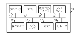
- FIG. 2 is a diagram illustrating an example of a hardware configuration of the user terminal 10.
- the user terminal 10 includes a processor 11, a memory 12, a communication interface 13, a touch sensor 14, an operation button 15, a display 16, a camera 17, and a storage 18.
- the processor 11 executes various processes according to the program stored in the memory 12.
- a CPU Central Processing Unit
- the memory 12 stores a program executed by the processor 11.
- a RAM Random Access Memory
- the communication interface 13 is connected to a network and performs communication via the network.
- the touch sensor 14 (an example of a detection unit) is provided so as to overlap the display 16.
- the touch sensor 14 detects the position of the indicator 20 that has touched the display 16.
- This position detection method may be a resistance film method or a capacitance method, or may be another method.
- the touch sensor 14 and the display 16 constitute a touch panel.
- the operation button 15 is used for operation of the user terminal 10.
- the display 16 (an example of a display unit) displays various types of information. For example, a liquid crystal display is used as the display 16.
- the camera 17 takes an image.
- a digital still camera is used as the camera 17.
- the storage 18 stores various programs and data.
- a flash memory or a hard disk drive is used as the storage 18, for example.
- FIG. 3 is a diagram illustrating an example of a functional configuration of the user terminal 10.
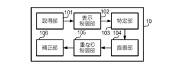
- the user terminal 10 functions as an acquisition unit 101, a display control unit 102, a specification unit 103, a drawing unit 104, an overlap control unit 105, and a correction unit 106. These functions are realized by one or more processors 11 executing programs stored in the memory 12.
- the acquisition unit 101 acquires a face image.
- the acquisition unit 101 acquires a user's face image captured by the camera 17.
- the acquisition unit 101 may acquire the user's face image from the storage 18.
- the display control unit 102 displays the face image acquired by the acquisition unit 101 on the display 16.
- the user performs an operation of designating a position on the face image displayed on the display 16 using the indicator 20.
- This operation is, for example, an operation of bringing the indicator 20 into contact with the face image on the surface of the display 16.
- a plurality of positions are designated.
- the position on the face image designated by the indicator 20 is detected by the touch sensor 14.
- the specifying unit 103 specifies the locus by sequentially connecting the positions detected by the touch sensor 14. However, depending on the shape of the trajectory, the trajectory may not be specified correctly.
- the drawing unit 104 draws a makeup object on the face image along the locus specified by the specifying unit 103.
- This makeup object has, for example, a linear shape centered on the locus.
- the color of the makeup object may be set to a color selected by a user operation.
- the thickness of the makeup object may be determined according to the makeup tool selected by the user's operation. For example, when a thick brush is selected, the thickness of the makeup object may be increased. On the other hand, when a thin brush is selected, the thickness of the makeup object may be reduced. Further, the shape, density, or blurring condition of the edge of the makeup object may change depending on the selected makeup tool.
- the shape of this end includes a stroke shape.
- the overlap control unit 105 increases the density of one or more overlapping portions between the makeup object drawn by the drawing unit 104 and another makeup object. This overlapping portion is obtained based on, for example, the position coordinates of the makeup object and the position coordinates of another makeup object. For example, the overlap control unit 105 may increase the density of the overlapping portion by multiplying a value indicating the color of the makeup object by a value indicating the color of the other makeup object.
- the correction unit 106 is located at a position corresponding to the change point.
- the density of one overlapping portion is corrected.
- the position corresponding to the change point is, for example, a position in an area defined so as to surround the point.
- the direction change amount an angle formed by two vectors that indicate the direction of the trajectory and touch at a certain point on the trajectory is used.
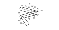
- FIG. 4 is a diagram for explaining a method for detecting a change point.
- the correction unit 106 obtains a vector indicating the direction of the locus 31 between adjacent points at points P1 to P5 determined on the locus 31 at predetermined intervals. For example, for the points P2 and P3, a vector V1 indicating the direction of the locus 31 between the points P2 and P3 is obtained. For the points P3 and P4, a vector V2 indicating the direction of the locus 31 between the points P3 and P4 is obtained.
- the correction unit 106 obtains an angle formed by two vectors that are in contact with each of the points P1 to P5. For example, for the vectors V1 and V2, the angle ⁇ formed by the vector V1 and the vector V2 is obtained. Here, it is assumed that the angle ⁇ is equal to or greater than the threshold value T1. In this case, the correction unit 106 detects a point P3 where the vector V1 and the vector V2 are in contact as a change point.
- the threshold T1 the minimum value of the amount of change in the direction in which such a phenomenon occurs is used.
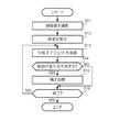
- FIG. 5 is a flowchart illustrating an example of a makeup simulation process according to the present embodiment. In this process, a makeup simulation using the user's face image is performed.
- step S ⁇ b> 11 the user captures his / her face image 61 using the camera 17.
- the acquisition unit 101 acquires a face image 61 captured by the camera 17.
- step S12 the display control unit 102 causes the display 16 to display a screen 161 used for the makeup simulation.
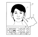
- FIG. 6 is a diagram illustrating an example of the screen 161.
- the screen 161 includes a user face image 61. Further, the screen 161 includes a plurality of color samples 62 used for selecting a makeup color. These color swatches 62 may include not only the color swatches 62 having different color types but also color swatches 62 having different color densities and textures. This texture changes depending on, for example, the amount of pearl, the amount of glitter, or the transparency. Note that the color of the color sample 62 may be the color of a product that is actually sold, or may be a color that is unrelated to the color of the product that is actually sold.
- the indicator 20 the user performs an operation of selecting a color sample 62 representing a desired makeup color from the color samples 62. This operation is, for example, a tap operation. Thereby, the color of makeup is selected.
- the screen 161 includes a plurality of icons 63 used for selecting a makeup tool.
- Each icon 63 includes an image representing a makeup tool. Note that this image may be an image representing a product that is actually sold, or an illustration representing a makeup tool.
- the user uses the indicator 20 to perform an operation of selecting an icon 63 representing a desired makeup tool from the plurality of icons 63. This operation is, for example, a tap operation. Thereby, a makeup tool is selected.
- step S ⁇ b> 13 the user performs an operation of applying makeup on the face image 61 using the indicator 20.
- a makeup object is drawn on the face image 61.
- the user performs an operation of painting a foundation color on the skin region of the face image 61.
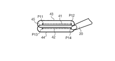
- FIG. 7 is a diagram illustrating an example of a makeup object.
- the user brings the indicator 20 into contact with the point P11 in the skin area of the face image 61. Subsequently, the user performs an operation of drawing the locus 41 by moving the indicator 20 to the point P12 while keeping the indicator 20 in contact with the surface of the display 16. After the user once separates the indicator 20 from the surface of the display 16 at the point 12, the user brings the indicator 20 into contact with the point P13. Subsequently, the user performs an operation of drawing the locus 42 by moving the indicator 20 to the point P14 while keeping the indicator 20 in contact with the surface of the display 16.
- the touch sensor 14 detects the position of the indicator 20 that has touched the surface of the display 16 at predetermined time intervals, and outputs position coordinates indicating the detected position.
- the specifying unit 103 specifies the trajectories 41 and 42 by sequentially connecting the positions indicated by the position coordinates output from the touch sensor 14.
- the drawing unit 104 draws the makeup objects 43 and 44 on the face image 61 along the trajectories 41 and 42 specified by the specifying unit.
- the makeup object 43 and the makeup object 44 have an overlapping portion 45.
- the overlap control unit 105 increases the density of the overlap portion 45. Thereby, the density of the overlapping part 45 is higher than the density of the other part of the makeup object 43 or 44.
- FIG. 8 is a diagram showing another example of a makeup object.
- the user brings the indicator 20 into contact with the point P1 in the skin region of the face image 61. Subsequently, the user performs an operation of drawing the locus 31 shown in FIG. 4 by moving the indicator 20 to the points P1 to P5 while keeping the indicator 20 in contact with the display 16.
- the touch sensor 14 detects the position of the indicator 20 in contact with the surface of the display 16 at predetermined time intervals, and outputs position coordinates indicating the detected position.
- the trajectory 31 changes its direction at the point P3 with a change amount equal to or greater than the threshold value T1.
- the specifying unit 103 specifies not the single trajectory 31 but two separate trajectories 32 and 33 by sequentially connecting the positions indicated by the position coordinates output from the touch sensor 14. The trajectories 32 and 33 are obtained by dividing the trajectory 31 at the point P3.
- the drawing unit 104 draws the makeup objects 34 and 35 on the face image 61 along the trajectories 32 and 33 specified by the specifying unit 103, respectively.
- the makeup object 34 and the makeup object 35 have an overlapping portion 36 (an example of a first overlapping portion).
- the overlap controller 105 increases the density of the overlap portion 36. As a result, the density of the overlapping portion 36 is higher than the density of the makeup object 34 or other parts of the makeup object 35.
- step S ⁇ b> 14 the correction unit 106 determines whether or not the locus of the position of the indicator 20 has a change point.
- the amount of change in the direction of the trajectories 41 and 42 is smaller than the threshold T1. In this case, it is determined that neither of the trajectories 41 and 42 has a change point.
- the flow proceeds to step S16 without performing the process of step S15.
- the trajectories 32 and 33 are connected at the point P3, and the amount of change between the direction of the trajectory 32 and the direction of the trajectory 33 is equal to or greater than the threshold value T1.
- this point P3 becomes a changing point, it is determined that the trajectories 32 and 33 have changing points.
- the flow proceeds to step S15.
- step S15 the correction unit 106 performs a correction process for correcting the density of the overlapping portion at the position corresponding to the change point.
- the density of the overlapping portion 36 at the position corresponding to the point P3 is corrected.
- the density of the part other than the overlapping part 36 in the makeup object 34 or 35 is D1
- the density of the overlapping part 36 is D2.
- the density D2 of the overlapping portion 36 is lowered to the density D1. Thereby, the density difference between the overlapping portion 36 and the other portions is eliminated.
- step S16 it is determined whether or not an operation for ending the simulation process has been performed.
- This operation is performed using, for example, the indicator 20 or the operation button 15.
- the flow returns to step S13 described above.
- various makeups such as foundation, eye shadow, teak, and lipstick are applied to the face image 61.
- the face image 61 after the makeup is applied is displayed on the display 16 every time the makeup is applied by the user's operation.
- the flow ends.
- the density of the overlapping portion where the density has increased against the user's intention is corrected.
- the simulation of the makeup along the user's intention can be performed.
- the present invention is not limited to the above-described embodiment.
- the embodiment may be modified as follows. Moreover, you may implement combining the following modifications.
- the density of the makeup object may change according to a predetermined parameter.
- the predetermined parameter includes, for example, the length of the trajectory.
- the drawing unit 104 may decrease the density of the makeup object as the locus becomes longer.
- the predetermined parameter may include pressure.
- the user terminal 10 includes a pressure sensor that measures the pressure applied to the surface of the display 16.
- the drawing unit 104 may increase the density of the makeup object as the pressure measured by the pressure sensor increases.
- the predetermined parameter may include the moving speed of the indicator 20.
- the user terminal 10 or the indicator 20 includes a speed sensor that measures the moving speed of the indicator 20.
- the drawing unit 104 may decrease the density of the makeup object as the moving speed measured by the speed sensor increases.
- the correction unit 106 may perform correction processing as follows.
- FIG. 9 is a diagram for explaining an example of correction processing according to this modification.
- the correction unit 106 extracts densities D3 (an example of the first density) and D4 (an example of the second density) from the reference regions 37 and 38 adjacent to the overlapping portion 36, respectively.
- D3 an example of the first density
- D4 an example of the second density
- the correcting unit 106 corrects the density of the overlapping portion 36 so as to gradually change from the density D3 to the density D4. Thereby, the density difference between the overlapping portion 36 and the reference regions 37 and 38 is reduced.
- Modification 2 when a predetermined condition is satisfied, the correction process may not be performed or the degree of the correction process may be reduced. For example, when the thickness of the makeup object is equal to or less than the threshold value T2, the correction process may not be performed. On the other hand, when the thickness of the makeup object is larger than the threshold value T2, correction processing is performed as in the above-described embodiment. This is because when the makeup object is large in thickness, the density difference between the overlapped portion and the other portion is conspicuous. On the other hand, when the makeup object is small in thickness, it is between the overlapped portion and the other portion. This is because it is difficult to recognize the difference in density.
- Modification 3 In the above-described embodiment, when the overlapping portion at the position corresponding to the change point is large, there is no intention of overlapping the color in the region close to the change point, while the color is overlapped in the region far from the change point. It is thought that there is intention to paint. Accordingly, in this case, for example, correction processing is performed for a predetermined range including the change point in the overlapping portion, while correction processing is not performed for other regions, or the degree of correction processing may be reduced. Good.
- FIG. 10 is a diagram for explaining an example of the correction process according to this modification.
- the correction unit 106 corrects the density of the region 39 in a predetermined range including the point P3 in the overlapping portion 36 as in the above-described embodiment. On the other hand, the correction unit 106 does not perform density correction for the region other than the region 39 in the overlapping portion 36.
- the density of the overlapping portion may be corrected regardless of whether the trajectory has a change point.
- This overlapping portion may include not only the overlapping portion at the position corresponding to the change point but also other overlapping portions.
- the correcting unit 106 may correct the density of all the overlapping portions of the makeup object corresponding to the locus.
- This predetermined area is an area where it is difficult to specify the position accurately using the indicator 20, for example.
- the makeup object may overlap when the indicator 20 contacts an unintended position.
- the density may be corrected for the overlapping portion located in the predetermined area.
- the correcting unit 106 when the frequency or frequency at which the indicator 20 has passed the predetermined area is equal to or greater than the threshold T3, or the time interval at which the indicator 20 has passed the predetermined area is equal to or less than the threshold T4, the correcting unit 106 The density of all overlapping portions of the makeup object corresponding to the locus may be corrected. This is because even when such a condition is satisfied, it is considered that there is no intention of overlapping colors on the overlapping portion.
- a person different from the user may perform an operation of applying makeup on the face image of the user using a terminal different from the user terminal 10.
- the person different from the user is, for example, an instructor such as a professional makeup artist. In this case, the user can see the makeup applied by the instructor and learn the makeup and makeup method that suits him.
- FIG. 11 is a diagram showing an example of the image processing system 1 according to this modification.
- the image processing system 1 includes a user terminal 10 (an example of a second terminal) and another terminal 30 (an example of a first terminal).
- the user terminal 10 and the terminal 30 are connected via a network 2 (an example of a communication line) such as the Internet.
- the terminal 30 is a computer such as a tablet terminal, a portable terminal, or a personal computer.
- the terminal 30 is used by an instructor.
- the terminal 30 has the same hardware configuration as that of the user terminal 10.
- the terminal 30 functions as the first display control unit 112 and the transmission unit 107 in addition to the specifying unit 103, the drawing unit 104, and the overlap control unit 105 described in the embodiment. These functions are realized by one or more processors executing a program stored in the memory.
- the transmission unit 107 is realized by a communication interface under the control of the processor.
- the first display control unit 112 has the same function as the display control unit 102 described in the embodiment.
- the transmission unit 107 transmits screen data indicating a screen displayed on the display (an example of a display unit) of the terminal 30 to the user terminal 10.
- the user terminal 10 functions as a second display control unit 108 and a correction control unit 109 in addition to the acquisition unit 101 and the correction unit 106 described in the embodiment. These functions are realized by one or more processors 11 executing programs stored in the memory 12.
- the second display control unit 108 causes the display 16 (an example of the second display unit) to display a screen corresponding to the screen data received from the terminal 30. Thereby, screen sharing is performed between the terminal 30 and the user terminal 10.
- the correction control unit 109 controls execution of correction processing by the correction unit 106 according to the screen size of the display 16.
- the user terminal 10 transmits image data indicating the user's face image 61 to the terminal 30 through the communication interface 13.
- the terminal 30 causes the first display control unit 112 to display the face image 61 indicated by the image data received from the user terminal 10 on the display.
- the instructor performs an operation of applying makeup on the face image 61 using the indicator.
- a makeup object is drawn on the face image 61 as in the embodiment.
- the terminal 30 causes the transmission unit 107 to transmit screen data indicating a display screen to the user terminal 10 at predetermined time intervals. At this time, position coordinates indicating the position of the overlapping portion at the position corresponding to the change point may be transmitted together with the screen data.
- User terminal 10 receives screen data from terminal 30 through communication interface 13. Subsequently, the user terminal 10 causes the display 16 to display a screen corresponding to the screen data by the second display control unit 108. When a makeup object having an overlapping portion at a position corresponding to the change point is included on the screen, the user terminal 10 performs a correction process for correcting the density of the overlapping portion by the correction unit 106 before displaying the screen. You may go. This overlapping portion is specified by the position coordinates received from the terminal 30.
- the user terminal 10 may control the execution of the correction process by the correction control unit 109 according to the screen size of the display 16. For example, when the screen size of the display 16 is larger than the threshold value T5, execution of the correction process may be permitted. On the other hand, when the screen size of the display 16 is equal to or smaller than the threshold T5, the execution of the correction process may be prohibited, or the degree of the correction process may be reduced. This is because when the screen size of the display 16 is small, the density difference between the overlapped portion and other portions is not noticeable. Thereby, the processing amount of the image processing system 1 can be reduced.
- the face image 61 on which makeup is applied by the instructor is displayed on the display 16 of the user terminal 10 in real time. Thereby, the user can browse a state where makeup is applied to his / her face image 61 by the instructor.
- voice data indicating the voice of the instructor may be transmitted from the terminal 30 to the user terminal 10 together with the screen data.
- the terminal 30 includes a microphone that collects voice and converts it into voice data.
- the user terminal 10 includes a speaker that outputs a sound corresponding to the sound data. Thereby, the voice of the instructor is output from the speaker of the user terminal 10 in real time.
- the user terminal 10 includes the correction unit 106, but the terminal 30 may include the correction unit 106 instead of the user terminal 10. In this case, correction processing is performed on the terminal 30 side. Then, screen data indicating a screen including the corrected makeup object is transmitted from the terminal 30 to the user terminal 10.
- the position on the face image is specified by the indicator 20 coming into contact with the surface of the display 16, but the method for specifying the position on the face image is not limited to this.
- the indicator 20 is the surface of the display 16.
- the position on the face image may be designated by being close to.
- the shape of the trajectory or the position of the change point is not limited to the example described in the embodiment.
- the trajectory may be a curve.
- a curvature may be used as the amount of change in direction in the trajectory.
- a point having a curvature greater than or equal to the threshold value in the trajectory may be the changing point.
- Modification 8 The steps of processing performed in the user terminal 10 or the image processing system 1 are not limited to the example described in the above-described embodiment. The steps of this process may be interchanged as long as there is no contradiction. In addition, the present invention may be provided as a method including steps of processing performed in the user terminal 10 or the image processing system 1.
- Modification 9 The present invention may be provided as a program executed on the user terminal 10 or the terminal 30.
- This program may be downloaded via a network such as the Internet.
- These programs are provided in a state where they are recorded on a computer-readable recording medium such as a magnetic recording medium (magnetic tape, magnetic disk, etc.), an optical recording medium (optical disk, etc.), a magneto-optical recording medium, or a semiconductor memory. May be.
Landscapes
- Engineering & Computer Science (AREA)
- Theoretical Computer Science (AREA)
- Physics & Mathematics (AREA)
- General Physics & Mathematics (AREA)
- General Engineering & Computer Science (AREA)
- Human Computer Interaction (AREA)
- Computer Hardware Design (AREA)
- Image Processing (AREA)
- Processing Or Creating Images (AREA)
Abstract
Description
本発明は、ユーザの意図に沿った化粧のシミュレーションを行うことを目的とする。
図1は、本実施形態に係るユーザ端末10の外観の一例を示す図である。ユーザ端末10は、タブレット端末、携帯端末、パーソナルコンピュータ等のコンピュータである。ユーザ端末10は、ユーザにより使用される。ユーザ端末10は、タッチパネルを備え、ユーザの指やスタイラスペン等の指示体20を用いた操作を受け付ける。ユーザ端末10は、指示体20を用いた操作に応じて、ユーザの顔画像を用いた化粧のシミュレーションを行う。
図5は、本実施形態に係る化粧のシミュレーション処理の一例を示すフローチャートである。この処理では、ユーザの顔画像を用いた化粧のシミュレーションが行われる。
本発明は上述した実施形態に限定されない。実施形態は、以下のように変形してもよい。また、以下の変形例を組み合わせて実施してもよい。
上述した実施形態において、所定のパラメータに応じて、化粧オブジェクトの濃度が変化してもよい。この所定のパラメータには、例えば軌跡の長さが含まれる。この場合、描画部104は、軌跡が長くなるほど、化粧オブジェクトの濃度を下げてもよい。
上述した実施形態において、所定の条件を満たす場合には、補正処理を行わず、又は補正処理の程度を下げてもよい。例えば、化粧オブジェクトの太さが閾値T2以下の場合には、補正処理を行わなくてもよい。一方、化粧オブジェクトの太さが閾値T2より大きい場合には、上述した実施形態と同様に補正処理を行う。これは、化粧オブジェクトの太さが大きい場合には、重なり部分と他の部分との間の濃度差が目立つ一方、化粧オブジェクトの太さが小さい場合には、重なり部分と他の部分との間の濃度差を認識し難いためである。
上述した実施形態において、変化点に対応する位置にある重なり部分が大きい場合には、変化点に近い領域については色を重ねて塗る意図はない一方、変化点から遠い領域については色を重ねて塗る意図があるとも考えられる。したがって、この場合には、例えばこの重なり部分において変化点を含む所定の範囲の領域については補正処理を行う一方、それ以外の領域については補正処理を行わず、又は補正処理の程度を下げてもよい。
上述した実施形態において、所定の条件を満たす場合には、軌跡が変化点を有するか否かに関わらず、重なり部分の濃度が補正されてもよい。この重なり部分には、変化点に対応する位置にある重なり部分だけでなく、それ以外の重なり部分が含まれてもよい。
上述した実施形態において、ユーザとは異なる人が、ユーザ端末10とは異なる端末を用いて、ユーザの顔画像に化粧を施す操作を行ってもよい。ユーザとは異なる人とは、例えばプロのメイクアップアーティスト等のインストラクターである。この場合、ユーザは、インストラクターによって施された化粧を見て、自分に似合う化粧や化粧の仕方を学ぶことができる。
上述した実施形態では、指示体20がディスプレイ16の表面に接触することにより、顔画像上の位置が指定されていたが、顔画像上の位置を指定する方法はこれに限定されない。例えば、ユーザ端末10が、ディスプレイ16の表面から法線方向に沿って形成される所定の検出範囲内に位置する指示体20を検出するセンサーを有する場合には、指示体20がディスプレイ16の表面に近接することにより、顔画像上の位置が指定されてもよい。
軌跡の形状又は変化点の位置は、実施形態で説明した例に限定されない。例えば、軌跡は曲線であってもよい。この場合、軌跡における方向の変化量として、曲率が用いられてもよい。この場合、軌跡において閾値以上の曲率を有する点が変化点となってもよい。
ユーザ端末10又は画像処理システム1において行われる処理のステップは、上述した実施形態で説明した例に限定されない。この処理のステップは、矛盾のない限り、入れ替えられてもよい。また、本発明は、ユーザ端末10又は画像処理システム1において行われる処理のステップを備える方法として提供されてもよい。
本発明は、ユーザ端末10又は端末30において実行されるプログラムとして提供されてもよい。このプログラムは、インターネット等のネットワークを介してダウンロードされてもよい。また、これらのプログラムは、磁気記録媒体(磁気テープ、磁気ディスクなど)、光記録媒体(光ディスクなど)、光磁気記録媒体、半導体メモリなどの、コンピュータが読取可能な記録媒体に記録した状態で提供されてもよい。
Claims (12)
- 顔画像を取得する取得部と、
前記取得された顔画像を表示部に表示させる表示制御部と、
指示体により指定された前記顔画像上の位置を検出する検出部と、
前記検出された位置を順次結ぶことにより特定される軌跡に沿って、前記顔画像上に化粧オブジェクトを描画する描画部と、
前記化粧オブジェクトと他の化粧オブジェクトとの1以上の重なり部分の濃度を上げる重なり制御部と、
前記軌跡が閾値以上の変化量で方向が変化する点を有する場合に、前記1以上の重なり部分に含まれる、前記点に対応する位置にある第1重なり部分の濃度を補正する補正部と
を備える画像処理システム。 - 前記化粧オブジェクトは、定められた太さを有する線状のオブジェクトである
請求項1に記載の画像処理システム。 - 前記補正部は、前記第1重なり部分の濃度を、前記化粧オブジェクトにおいて前記1以上の重なり部分以外の部分の濃度に下げる
請求項1又は2に記載の画像処理システム。 - 前記描画部は、所定のパラメータに応じて、前記化粧オブジェクトの濃度を変化させ、
前記補正部は、前記化粧オブジェクト又は前記他の化粧オブジェクトにおいて前記第1重なり部分を挟んで隣り合う2つの領域から第1濃度と第2濃度とをそれぞれ抽出し、前記第1濃度から前記第2濃度へと徐々に変化するように、前記第1重なり部分の濃度を補正する
請求項1から3のいずれか1項に記載の画像処理システム。 - 前記所定のパラメータは、前記軌跡の長さを含み、
前記描画部は、前記軌跡の長さに応じて、前記化粧オブジェクトの濃度を変化させる
請求項4に記載の画像処理システム。 - 前記補正部は、所定の条件を満たす場合には、前記軌跡が前記点を有するか否かに関わらず、前記1以上の重なり部分に含まれる、前記第1重なり部分とは異なる第2重なり部分の濃度を補正する
請求項1から5のいずれか1項に記載の画像処理システム。 - 前記所定の条件は、前記第2重なり部分が前記顔画像の所定の領域に位置するという条件、又は前記軌跡が前記所定の領域を通った回数、頻度、若しくは時間間隔に応じた条件である
請求項6に記載の画像処理システム。 - 通信回線を介して接続され、画面共有を行う第1端末及び第2端末と、
前記第1端末において、前記表示制御部として機能する第1表示制御部と、
前記第1端末において、前記表示部に表示された画面を示す画面データを前記第2端末に送信する送信部と、
前記第2端末において、前記第1端末から受信した前記画面データに応じた画面を第2表示部に表示させる第2表示制御部とを備える
請求項1から7のいずれか1項に記載の画像処理システム。 - 前記第2表示部の画面サイズに応じて、前記補正部による補正の実行を制御する補正制御部をさらに備える
請求項8に記載の画像処理システム。 - 顔画像を取得する取得部と、
前記取得された顔画像を表示部に表示させる表示制御部と、
指示体により指定された前記顔画像上の位置を検出する検出部と、
前記検出された位置を順次結ぶことにより特定される軌跡に沿って、前記顔画像上に化粧オブジェクトを描画する描画部と、
前記化粧オブジェクトと他の化粧オブジェクトとの1以上の重なり部分の濃度を上げる重なり制御部と、
前記軌跡が閾値以上の変化量で方向が変化する点を有する場合に、前記1以上の重なり部分に含まれる、前記点に対応する位置にある第1重なり部分の濃度を補正する補正部と
を備える画像処理装置。 - 顔画像を取得するステップと、
前記取得された顔画像を表示部に表示させるステップと、
指示体により指定された前記顔画像上の位置を検出するステップと、
前記検出された位置を順次結ぶことにより特定される軌跡に沿って、前記顔画像上に化粧オブジェクトを描画するステップと、
前記化粧オブジェクトと他の化粧オブジェクトとの1以上の重なり部分の濃度を上げるステップと、
前記軌跡が閾値以上の変化量で方向が変化する点を有する場合に、前記1以上の重なり部分に含まれる、前記点に対応する位置にある第1重なり部分の濃度を補正するステップと
を備える画像処理方法。 - コンピュータに、
顔画像を取得するステップと、
前記取得された顔画像を表示部に表示させるステップと、
指示体により指定された前記顔画像上の位置を検出するステップと、
前記検出された位置を順次結ぶことにより特定される軌跡に沿って、前記顔画像上に化粧オブジェクトを描画するステップと、
前記化粧オブジェクトと他の化粧オブジェクトとの1以上の重なり部分の濃度を上げるステップと、
前記軌跡が閾値以上の変化量で方向が変化する点を有する場合に、前記1以上の重なり部分に含まれる、前記点に対応する位置にある第1重なり部分の濃度を補正するステップと
を実行させるためのプログラム。
Priority Applications (3)
| Application Number | Priority Date | Filing Date | Title |
|---|---|---|---|
| US15/326,177 US10529102B2 (en) | 2016-09-09 | 2016-09-09 | Image processing system, image processing apparatus, image processing method, and program |
| PCT/JP2016/076572 WO2018047287A1 (ja) | 2016-09-09 | 2016-09-09 | 画像処理システム、画像処理装置、画像処理方法、及びプログラム |
| JP2016573140A JP6174277B1 (ja) | 2016-09-09 | 2016-09-09 | 画像処理システム、画像処理装置、画像処理方法、及びプログラム |
Applications Claiming Priority (1)
| Application Number | Priority Date | Filing Date | Title |
|---|---|---|---|
| PCT/JP2016/076572 WO2018047287A1 (ja) | 2016-09-09 | 2016-09-09 | 画像処理システム、画像処理装置、画像処理方法、及びプログラム |
Publications (1)
| Publication Number | Publication Date |
|---|---|
| WO2018047287A1 true WO2018047287A1 (ja) | 2018-03-15 |
Family
ID=59505155
Family Applications (1)
| Application Number | Title | Priority Date | Filing Date |
|---|---|---|---|
| PCT/JP2016/076572 Ceased WO2018047287A1 (ja) | 2016-09-09 | 2016-09-09 | 画像処理システム、画像処理装置、画像処理方法、及びプログラム |
Country Status (3)
| Country | Link |
|---|---|
| US (1) | US10529102B2 (ja) |
| JP (1) | JP6174277B1 (ja) |
| WO (1) | WO2018047287A1 (ja) |
Cited By (1)
| Publication number | Priority date | Publication date | Assignee | Title |
|---|---|---|---|---|
| JP2021051518A (ja) * | 2019-09-24 | 2021-04-01 | カシオ計算機株式会社 | 画像処理装置、メイクシミュレーション装置、画像処理方法及びプログラム |
Families Citing this family (3)
| Publication number | Priority date | Publication date | Assignee | Title |
|---|---|---|---|---|
| US10671837B2 (en) * | 2015-09-08 | 2020-06-02 | Nec Corporation | Face recognition system, face recognition method, display control apparatus, display control method, and display control program |
| US10691932B2 (en) | 2018-02-06 | 2020-06-23 | Perfect Corp. | Systems and methods for generating and analyzing user behavior metrics during makeup consultation sessions |
| US12444108B2 (en) * | 2020-10-15 | 2025-10-14 | Coty Inc. | Dynamic color adjustment in augmented reality |
Citations (3)
| Publication number | Priority date | Publication date | Assignee | Title |
|---|---|---|---|---|
| JPH08202893A (ja) * | 1995-01-27 | 1996-08-09 | Sony Corp | 掠描画方法及び掠描画装置 |
| JP2005092588A (ja) * | 2003-09-18 | 2005-04-07 | Hitachi Software Eng Co Ltd | 合成画像プリント装置及び画像編集方法 |
| JP2007257655A (ja) * | 2007-04-26 | 2007-10-04 | Wacom-It Co Ltd | 描画装置および描画プログラム |
Family Cites Families (2)
| Publication number | Priority date | Publication date | Assignee | Title |
|---|---|---|---|---|
| JP2009064423A (ja) * | 2007-08-10 | 2009-03-26 | Shiseido Co Ltd | メイクアップシミュレーションシステム、メイクアップシミュレーション装置、メイクアップシミュレーション方法およびメイクアップシミュレーションプログラム |
| CN104797165A (zh) * | 2013-08-30 | 2015-07-22 | 松下知识产权经营株式会社 | 化妆辅助装置、化妆辅助方法以及化妆辅助程序 |
-
2016
- 2016-09-09 JP JP2016573140A patent/JP6174277B1/ja active Active
- 2016-09-09 US US15/326,177 patent/US10529102B2/en active Active
- 2016-09-09 WO PCT/JP2016/076572 patent/WO2018047287A1/ja not_active Ceased
Patent Citations (3)
| Publication number | Priority date | Publication date | Assignee | Title |
|---|---|---|---|---|
| JPH08202893A (ja) * | 1995-01-27 | 1996-08-09 | Sony Corp | 掠描画方法及び掠描画装置 |
| JP2005092588A (ja) * | 2003-09-18 | 2005-04-07 | Hitachi Software Eng Co Ltd | 合成画像プリント装置及び画像編集方法 |
| JP2007257655A (ja) * | 2007-04-26 | 2007-10-04 | Wacom-It Co Ltd | 描画装置および描画プログラム |
Cited By (2)
| Publication number | Priority date | Publication date | Assignee | Title |
|---|---|---|---|---|
| JP2021051518A (ja) * | 2019-09-24 | 2021-04-01 | カシオ計算機株式会社 | 画像処理装置、メイクシミュレーション装置、画像処理方法及びプログラム |
| JP7476505B2 (ja) | 2019-09-24 | 2024-05-01 | カシオ計算機株式会社 | 画像処理装置、メイクシミュレーション装置、画像処理方法及びプログラム |
Also Published As
| Publication number | Publication date |
|---|---|
| JPWO2018047287A1 (ja) | 2018-09-06 |
| US10529102B2 (en) | 2020-01-07 |
| US20190347840A1 (en) | 2019-11-14 |
| JP6174277B1 (ja) | 2017-08-02 |
Similar Documents
| Publication | Publication Date | Title |
|---|---|---|
| KR101944112B1 (ko) | 사용자 저작 스티커를 생성하는 방법 및 장치, 사용자 저작 스티커 공유 시스템 | |
| JP7212067B2 (ja) | 画像合成方法及び装置 | |
| CN111047526B (zh) | 一种图像处理方法、装置、电子设备及存储介质 | |
| US20130069867A1 (en) | Information processing apparatus and method and program | |
| JP6174277B1 (ja) | 画像処理システム、画像処理装置、画像処理方法、及びプログラム | |
| KR20170009979A (ko) | 터치 입력을 위한 방법 및 시스템 | |
| CN105045399B (zh) | 一种具有3d摄像组件的电子设备 | |
| WO2015029371A1 (ja) | メイクアップ支援装置、メイクアップ支援方法、およびメイクアップ支援プログラム | |
| CN108920066B (zh) | 触摸屏滑动调整方法、调整装置及触控设备 | |
| CN105512605A (zh) | 人脸图像处理方法及装置 | |
| CN109522869A (zh) | 人脸图像处理方法、装置、终端设备及计算机存储介质 | |
| US10488918B2 (en) | Analysis of user interface interactions within a virtual reality environment | |
| CN110427849A (zh) | 人脸姿态确定方法、装置、存储介质和电子设备 | |
| JP2020154773A (ja) | 画像処理装置、画像処理方法及び画像処理システム | |
| US20170103557A1 (en) | Localized brush stroke preview | |
| CN103679130B (zh) | 手追踪方法、手追踪设备和手势识别系统 | |
| CN105068662B (zh) | 一种用于人机交互的电子设备 | |
| US10558850B2 (en) | Body information analysis apparatus and method of simulating face shape by using same | |
| KR102147930B1 (ko) | 포즈 인식 방법 및 장치 | |
| KR20190132885A (ko) | 영상으로부터 손을 검출하는 장치, 방법 및 컴퓨터 프로그램 | |
| CN107450717A (zh) | 一种信息处理方法及穿戴式设备 | |
| CN105320437A (zh) | 选择字符或图像的方法及计算设备 | |
| US10496873B2 (en) | Body information analysis apparatus and method of detecting face shape by using same | |
| CN112613374A (zh) | 人脸可见区域解析与分割方法、人脸上妆方法及移动终端 | |
| CN114860072A (zh) | 一种基于单目摄像头的手势识别交互设备 |
Legal Events
| Date | Code | Title | Description |
|---|---|---|---|
| WWE | Wipo information: entry into national phase |
Ref document number: 2016573140 Country of ref document: JP |
|
| 121 | Ep: the epo has been informed by wipo that ep was designated in this application |
Ref document number: 16915705 Country of ref document: EP Kind code of ref document: A1 |
|
| NENP | Non-entry into the national phase |
Ref country code: DE |
|
| 32PN | Ep: public notification in the ep bulletin as address of the adressee cannot be established |
Free format text: NOTING OF LOSS OF RIGHTS PURSUANT TO RULE 112(1) EPC (EPO FORM 1205A DATED 14/06/2019) |
|
| 122 | Ep: pct application non-entry in european phase |
Ref document number: 16915705 Country of ref document: EP Kind code of ref document: A1 |