WO2018047259A1 - Fuel cell system and method for controlling same - Google Patents
Fuel cell system and method for controlling same Download PDFInfo
- Publication number
- WO2018047259A1 WO2018047259A1 PCT/JP2016/076349 JP2016076349W WO2018047259A1 WO 2018047259 A1 WO2018047259 A1 WO 2018047259A1 JP 2016076349 W JP2016076349 W JP 2016076349W WO 2018047259 A1 WO2018047259 A1 WO 2018047259A1
- Authority
- WO
- WIPO (PCT)
- Prior art keywords
- fuel cell
- recovery control
- stack
- cathode
- cell system
- Prior art date
Links
Images


Classifications
-
- H—ELECTRICITY
- H01—ELECTRIC ELEMENTS
- H01M—PROCESSES OR MEANS, e.g. BATTERIES, FOR THE DIRECT CONVERSION OF CHEMICAL ENERGY INTO ELECTRICAL ENERGY
- H01M8/00—Fuel cells; Manufacture thereof
- H01M8/04—Auxiliary arrangements, e.g. for control of pressure or for circulation of fluids
- H01M8/04223—Auxiliary arrangements, e.g. for control of pressure or for circulation of fluids during start-up or shut-down; Depolarisation or activation, e.g. purging; Means for short-circuiting defective fuel cells
- H01M8/04225—Auxiliary arrangements, e.g. for control of pressure or for circulation of fluids during start-up or shut-down; Depolarisation or activation, e.g. purging; Means for short-circuiting defective fuel cells during start-up
-
- H—ELECTRICITY
- H01—ELECTRIC ELEMENTS
- H01M—PROCESSES OR MEANS, e.g. BATTERIES, FOR THE DIRECT CONVERSION OF CHEMICAL ENERGY INTO ELECTRICAL ENERGY
- H01M8/00—Fuel cells; Manufacture thereof
- H01M8/04—Auxiliary arrangements, e.g. for control of pressure or for circulation of fluids
- H01M8/04082—Arrangements for control of reactant parameters, e.g. pressure or concentration
- H01M8/04089—Arrangements for control of reactant parameters, e.g. pressure or concentration of gaseous reactants
- H01M8/04119—Arrangements for control of reactant parameters, e.g. pressure or concentration of gaseous reactants with simultaneous supply or evacuation of electrolyte; Humidifying or dehumidifying
- H01M8/04156—Arrangements for control of reactant parameters, e.g. pressure or concentration of gaseous reactants with simultaneous supply or evacuation of electrolyte; Humidifying or dehumidifying with product water removal
- H01M8/04179—Arrangements for control of reactant parameters, e.g. pressure or concentration of gaseous reactants with simultaneous supply or evacuation of electrolyte; Humidifying or dehumidifying with product water removal by purging or increasing flow or pressure of reactants
-
- H—ELECTRICITY
- H01—ELECTRIC ELEMENTS
- H01M—PROCESSES OR MEANS, e.g. BATTERIES, FOR THE DIRECT CONVERSION OF CHEMICAL ENERGY INTO ELECTRICAL ENERGY
- H01M8/00—Fuel cells; Manufacture thereof
- H01M8/04—Auxiliary arrangements, e.g. for control of pressure or for circulation of fluids
- H01M8/04298—Processes for controlling fuel cells or fuel cell systems
- H01M8/04694—Processes for controlling fuel cells or fuel cell systems characterised by variables to be controlled
- H01M8/04828—Humidity; Water content
- H01M8/0485—Humidity; Water content of the electrolyte
-
- H—ELECTRICITY
- H01—ELECTRIC ELEMENTS
- H01M—PROCESSES OR MEANS, e.g. BATTERIES, FOR THE DIRECT CONVERSION OF CHEMICAL ENERGY INTO ELECTRICAL ENERGY
- H01M8/00—Fuel cells; Manufacture thereof
- H01M8/04—Auxiliary arrangements, e.g. for control of pressure or for circulation of fluids
- H01M8/04082—Arrangements for control of reactant parameters, e.g. pressure or concentration
- H01M8/04089—Arrangements for control of reactant parameters, e.g. pressure or concentration of gaseous reactants
- H01M8/04119—Arrangements for control of reactant parameters, e.g. pressure or concentration of gaseous reactants with simultaneous supply or evacuation of electrolyte; Humidifying or dehumidifying
- H01M8/04126—Humidifying
-
- H—ELECTRICITY
- H01—ELECTRIC ELEMENTS
- H01M—PROCESSES OR MEANS, e.g. BATTERIES, FOR THE DIRECT CONVERSION OF CHEMICAL ENERGY INTO ELECTRICAL ENERGY
- H01M8/00—Fuel cells; Manufacture thereof
- H01M8/04—Auxiliary arrangements, e.g. for control of pressure or for circulation of fluids
- H01M8/04082—Arrangements for control of reactant parameters, e.g. pressure or concentration
- H01M8/04201—Reactant storage and supply, e.g. means for feeding, pipes
-
- H—ELECTRICITY
- H01—ELECTRIC ELEMENTS
- H01M—PROCESSES OR MEANS, e.g. BATTERIES, FOR THE DIRECT CONVERSION OF CHEMICAL ENERGY INTO ELECTRICAL ENERGY
- H01M8/00—Fuel cells; Manufacture thereof
- H01M8/04—Auxiliary arrangements, e.g. for control of pressure or for circulation of fluids
- H01M8/04223—Auxiliary arrangements, e.g. for control of pressure or for circulation of fluids during start-up or shut-down; Depolarisation or activation, e.g. purging; Means for short-circuiting defective fuel cells
- H01M8/04253—Means for solving freezing problems
-
- H—ELECTRICITY
- H01—ELECTRIC ELEMENTS
- H01M—PROCESSES OR MEANS, e.g. BATTERIES, FOR THE DIRECT CONVERSION OF CHEMICAL ENERGY INTO ELECTRICAL ENERGY
- H01M8/00—Fuel cells; Manufacture thereof
- H01M8/04—Auxiliary arrangements, e.g. for control of pressure or for circulation of fluids
- H01M8/04298—Processes for controlling fuel cells or fuel cell systems
- H01M8/043—Processes for controlling fuel cells or fuel cell systems applied during specific periods
- H01M8/04302—Processes for controlling fuel cells or fuel cell systems applied during specific periods applied during start-up
-
- H—ELECTRICITY
- H01—ELECTRIC ELEMENTS
- H01M—PROCESSES OR MEANS, e.g. BATTERIES, FOR THE DIRECT CONVERSION OF CHEMICAL ENERGY INTO ELECTRICAL ENERGY
- H01M8/00—Fuel cells; Manufacture thereof
- H01M8/04—Auxiliary arrangements, e.g. for control of pressure or for circulation of fluids
- H01M8/04298—Processes for controlling fuel cells or fuel cell systems
- H01M8/04313—Processes for controlling fuel cells or fuel cell systems characterised by the detection or assessment of variables; characterised by the detection or assessment of failure or abnormal function
- H01M8/0432—Temperature; Ambient temperature
-
- H—ELECTRICITY
- H01—ELECTRIC ELEMENTS
- H01M—PROCESSES OR MEANS, e.g. BATTERIES, FOR THE DIRECT CONVERSION OF CHEMICAL ENERGY INTO ELECTRICAL ENERGY
- H01M8/00—Fuel cells; Manufacture thereof
- H01M8/04—Auxiliary arrangements, e.g. for control of pressure or for circulation of fluids
- H01M8/04298—Processes for controlling fuel cells or fuel cell systems
- H01M8/04313—Processes for controlling fuel cells or fuel cell systems characterised by the detection or assessment of variables; characterised by the detection or assessment of failure or abnormal function
- H01M8/04537—Electric variables
- H01M8/04544—Voltage
- H01M8/04552—Voltage of the individual fuel cell
-
- H—ELECTRICITY
- H01—ELECTRIC ELEMENTS
- H01M—PROCESSES OR MEANS, e.g. BATTERIES, FOR THE DIRECT CONVERSION OF CHEMICAL ENERGY INTO ELECTRICAL ENERGY
- H01M8/00—Fuel cells; Manufacture thereof
- H01M8/04—Auxiliary arrangements, e.g. for control of pressure or for circulation of fluids
- H01M8/04298—Processes for controlling fuel cells or fuel cell systems
- H01M8/04313—Processes for controlling fuel cells or fuel cell systems characterised by the detection or assessment of variables; characterised by the detection or assessment of failure or abnormal function
- H01M8/04537—Electric variables
- H01M8/04544—Voltage
- H01M8/04559—Voltage of fuel cell stacks
-
- H—ELECTRICITY
- H01—ELECTRIC ELEMENTS
- H01M—PROCESSES OR MEANS, e.g. BATTERIES, FOR THE DIRECT CONVERSION OF CHEMICAL ENERGY INTO ELECTRICAL ENERGY
- H01M8/00—Fuel cells; Manufacture thereof
- H01M8/04—Auxiliary arrangements, e.g. for control of pressure or for circulation of fluids
- H01M8/04298—Processes for controlling fuel cells or fuel cell systems
- H01M8/04313—Processes for controlling fuel cells or fuel cell systems characterised by the detection or assessment of variables; characterised by the detection or assessment of failure or abnormal function
- H01M8/04537—Electric variables
- H01M8/04634—Other electric variables, e.g. resistance or impedance
- H01M8/04649—Other electric variables, e.g. resistance or impedance of fuel cell stacks
-
- H—ELECTRICITY
- H01—ELECTRIC ELEMENTS
- H01M—PROCESSES OR MEANS, e.g. BATTERIES, FOR THE DIRECT CONVERSION OF CHEMICAL ENERGY INTO ELECTRICAL ENERGY
- H01M8/00—Fuel cells; Manufacture thereof
- H01M8/04—Auxiliary arrangements, e.g. for control of pressure or for circulation of fluids
- H01M8/04298—Processes for controlling fuel cells or fuel cell systems
- H01M8/04694—Processes for controlling fuel cells or fuel cell systems characterised by variables to be controlled
- H01M8/04746—Pressure; Flow
- H01M8/04753—Pressure; Flow of fuel cell reactants
-
- H—ELECTRICITY
- H01—ELECTRIC ELEMENTS
- H01M—PROCESSES OR MEANS, e.g. BATTERIES, FOR THE DIRECT CONVERSION OF CHEMICAL ENERGY INTO ELECTRICAL ENERGY
- H01M8/00—Fuel cells; Manufacture thereof
- H01M8/04—Auxiliary arrangements, e.g. for control of pressure or for circulation of fluids
- H01M8/04298—Processes for controlling fuel cells or fuel cell systems
- H01M8/04694—Processes for controlling fuel cells or fuel cell systems characterised by variables to be controlled
- H01M8/04858—Electric variables
- H01M8/04895—Current
- H01M8/0491—Current of fuel cell stacks
-
- H—ELECTRICITY
- H01—ELECTRIC ELEMENTS
- H01M—PROCESSES OR MEANS, e.g. BATTERIES, FOR THE DIRECT CONVERSION OF CHEMICAL ENERGY INTO ELECTRICAL ENERGY
- H01M8/00—Fuel cells; Manufacture thereof
- H01M8/10—Fuel cells with solid electrolytes
- H01M2008/1095—Fuel cells with polymeric electrolytes
-
- H—ELECTRICITY
- H01—ELECTRIC ELEMENTS
- H01M—PROCESSES OR MEANS, e.g. BATTERIES, FOR THE DIRECT CONVERSION OF CHEMICAL ENERGY INTO ELECTRICAL ENERGY
- H01M2250/00—Fuel cells for particular applications; Specific features of fuel cell system
- H01M2250/20—Fuel cells in motive systems, e.g. vehicle, ship, plane
-
- H—ELECTRICITY
- H01—ELECTRIC ELEMENTS
- H01M—PROCESSES OR MEANS, e.g. BATTERIES, FOR THE DIRECT CONVERSION OF CHEMICAL ENERGY INTO ELECTRICAL ENERGY
- H01M8/00—Fuel cells; Manufacture thereof
- H01M8/04—Auxiliary arrangements, e.g. for control of pressure or for circulation of fluids
- H01M8/04298—Processes for controlling fuel cells or fuel cell systems
- H01M8/04313—Processes for controlling fuel cells or fuel cell systems characterised by the detection or assessment of variables; characterised by the detection or assessment of failure or abnormal function
- H01M8/04492—Humidity; Ambient humidity; Water content
-
- H—ELECTRICITY
- H01—ELECTRIC ELEMENTS
- H01M—PROCESSES OR MEANS, e.g. BATTERIES, FOR THE DIRECT CONVERSION OF CHEMICAL ENERGY INTO ELECTRICAL ENERGY
- H01M8/00—Fuel cells; Manufacture thereof
- H01M8/04—Auxiliary arrangements, e.g. for control of pressure or for circulation of fluids
- H01M8/04298—Processes for controlling fuel cells or fuel cell systems
- H01M8/04694—Processes for controlling fuel cells or fuel cell systems characterised by variables to be controlled
- H01M8/04828—Humidity; Water content
-
- Y—GENERAL TAGGING OF NEW TECHNOLOGICAL DEVELOPMENTS; GENERAL TAGGING OF CROSS-SECTIONAL TECHNOLOGIES SPANNING OVER SEVERAL SECTIONS OF THE IPC; TECHNICAL SUBJECTS COVERED BY FORMER USPC CROSS-REFERENCE ART COLLECTIONS [XRACs] AND DIGESTS
- Y02—TECHNOLOGIES OR APPLICATIONS FOR MITIGATION OR ADAPTATION AGAINST CLIMATE CHANGE
- Y02E—REDUCTION OF GREENHOUSE GAS [GHG] EMISSIONS, RELATED TO ENERGY GENERATION, TRANSMISSION OR DISTRIBUTION
- Y02E60/00—Enabling technologies; Technologies with a potential or indirect contribution to GHG emissions mitigation
- Y02E60/30—Hydrogen technology
- Y02E60/50—Fuel cells
-
- Y—GENERAL TAGGING OF NEW TECHNOLOGICAL DEVELOPMENTS; GENERAL TAGGING OF CROSS-SECTIONAL TECHNOLOGIES SPANNING OVER SEVERAL SECTIONS OF THE IPC; TECHNICAL SUBJECTS COVERED BY FORMER USPC CROSS-REFERENCE ART COLLECTIONS [XRACs] AND DIGESTS
- Y02—TECHNOLOGIES OR APPLICATIONS FOR MITIGATION OR ADAPTATION AGAINST CLIMATE CHANGE
- Y02T—CLIMATE CHANGE MITIGATION TECHNOLOGIES RELATED TO TRANSPORTATION
- Y02T90/00—Enabling technologies or technologies with a potential or indirect contribution to GHG emissions mitigation
- Y02T90/40—Application of hydrogen technology to transportation, e.g. using fuel cells
Definitions
- the present invention relates to a fuel cell system that executes control at the time of low temperature startup of the fuel cell and a control method thereof.
- temperature increase control is performed to raise the temperature of the fuel cell by heat generated by the power generation of the fuel cell, and moisture inside the fuel cell (especially in the cathode) is removed.
- a cold start operation including a recovery operation is performed. This recovery operation is performed in order to suppress the output performance from being deteriorated due to the so-called flooding state of the fuel cell.
- JP4575673B2 evaporates water in the cathode electrode by supplying dry air to the cathode electrode at the time of low temperature start-up of the fuel cell (hereinafter also referred to as “dry air supply process”).
- dry air supply process There has been proposed a fuel cell system that discharges to a cathode discharge channel.
- the ambient environment temperature (the temperature of the fuel cell or the dry air temperature) is raised so that moisture is discharged from the cathode to the outside by dry air. It is necessary to raise the temperature to a certain temperature.
- the present invention has been made paying attention to such problems, and an object of the present invention is to provide a fuel cell system and a control method therefor that can shorten the time required for low-temperature startup operation of the fuel cell.
- a cold start operation in a fuel cell system having a fuel cell, it is determined whether the operation is a cold start operation or a normal operation, and it is determined that the operation is a cold start operation. Then, recovery control is executed to increase the concentration gradient of water in the electrolyte membrane of the fuel cell compared to the operation during normal operation.
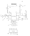
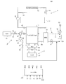
- FIG. 1 is a diagram showing a configuration of a fuel cell system according to a first embodiment of the present invention.
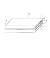
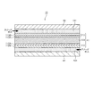
- FIG. 2 is a perspective view of the fuel battery cell. 3 is a cross-sectional view of the fuel cell of FIG. 2 taken along the line II-II.
- FIG. 4 is a flowchart for explaining the flow of processing when starting up the fuel cell system.
- FIG. 5 is a flowchart for explaining the flow of the cold start operation of the first embodiment.
- FIG. 6 is a timing chart for explaining the change over time from the low temperature startup operation to the normal operation in the first embodiment.
- FIG. 7 is a diagram for explaining the operational effect of the recovery control.
- FIG. 1 is a diagram showing a configuration of a fuel cell system according to a first embodiment of the present invention.
- FIG. 2 is a perspective view of the fuel battery cell. 3 is a cross-sectional view of the fuel cell of FIG. 2 taken along the line II-II.
- FIG. 4 is a flowchart for
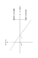
- FIG. 8 is a graph for explaining the relationship between the water transfer amount to the electrolyte membrane and the water evaporation amount to the cathode flow path according to the stack temperature.
- FIG. 9 is a graph for explaining the recovery effect of the output performance by the recovery control of this embodiment.
- FIG. 10 is a timing chart for explaining the change over time from the low temperature startup operation to the normal operation in the second embodiment.
- FIG. 11 is a timing chart for explaining the change over time of the low-temperature startup operation of the third embodiment.
- FIG. 12 is a flowchart for explaining the flow of the cold start operation of the fourth embodiment.
- FIG. 13 is a timing chart for explaining the change over time of the low-temperature startup operation according to the fourth embodiment.
- FIG. 14 is a graph showing the difference in the time change of the cell voltage before and after the recovery of the output performance.
- FIG. 15 is a flowchart for explaining the flow of the cold start operation of the fifth embodiment.
- FIG. 16 is a graph showing the time change of the cell voltage differential value before and after the recovery of the output performance.
- FIG. 17 is a diagram illustrating a configuration of a fuel cell system according to the sixth embodiment.
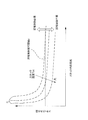
- FIG. 18 is a graph showing the relationship between stack internal resistance and stack water content.
- FIG. 19 is a flowchart for explaining the flow of the cold start operation of the sixth embodiment.
- FIG. 20 is a graph showing the relationship between the stack temperature and the stack internal resistance in the seventh embodiment.
- FIG. 21 is a map showing the relationship between stack internal resistance, stack temperature, and stack moisture content.
- FIG. 22 is a diagram showing a configuration of a fuel cell system according to the eighth embodiment.
- FIG. 23 is a diagram for explaining the background art.
- FIG. 1 is a diagram illustrating an example of a configuration of a fuel cell system 100 according to the first embodiment.
- the fuel cell system 100 shown in the figure supplies an anode gas (hydrogen) as a fuel gas and a cathode gas as an oxidizing gas (air) to the fuel cell stack 1 to cause power generation.
- anode gas hydrogen
- a cathode gas as an oxidizing gas (air)
- the fuel cell system 100 includes a fuel cell stack 1, a cathode gas supply / discharge device 2, an anode gas supply / discharge device 3, a stack cooling device 4, a power system 5, and a control unit 200.
- the fuel cell stack 1 is a stacked battery in which a plurality of fuel cells are stacked.
- the fuel battery cell is configured by sandwiching an electrolyte membrane between an anode electrode (fuel electrode) and a cathode electrode (oxidant electrode).
- anode gas is supplied to the anode electrode
- cathode gas is supplied to the cathode electrode, and electricity is generated by using these gases.
- the main electrochemical reactions that proceed during power generation at both the anode and cathode electrodes are as follows.
- Anode electrode 2H 2 ⁇ 4H + + 4e ⁇ (1)
- Cathode electrode 4H + + 4e ⁇ + O 2 ⁇ 2H 2 O (2)
- FIG. 2 and 3 are diagrams for explaining the configuration of the fuel battery cell.
- FIG. 2 is a perspective view of the fuel battery cell
- FIG. 3 is a cross-sectional view taken along the line II-II of the fuel battery cell of FIG.
- the fuel cell 10 includes a membrane electrode assembly (MEA) 11 and an anode separator 12 and a cathode separator 13 disposed so as to sandwich the membrane electrode assembly 11.
- MEA membrane electrode assembly
- the membrane electrode assembly 11 includes an electrolyte membrane 111, an anode electrode 112, and a cathode electrode 113.
- the membrane electrode assembly 11 has an anode electrode 112 on one surface side of the electrolyte membrane 111 and a cathode electrode 113 on the other surface side.
- the electrolyte membrane 111 is a proton conductive ion exchange membrane formed of a fluorine-based resin.
- the electrolyte membrane 111 exhibits good electrical conductivity in a wet state.
- the anode electrode 112 includes an anode catalyst layer 112A and a gas diffusion layer 112B.
- the anode catalyst layer 112A is composed of a catalyst material composed of carbon black particles (carbon support) on which platinum or the like is supported, and an electrolyte (hereinafter also referred to as “anode electrolyte”) present between the catalyst materials. Then, vacancies (hereinafter also referred to as “anode vacancies”) are formed in portions where the catalyst material and the anode electrolyte do not exist. Furthermore, the anode catalyst layer 112 ⁇ / b> A is provided in contact with the electrolyte membrane 111.
- the gas diffusion layer 112B is disposed outside the anode catalyst layer 112A.
- the gas diffusion layer 112B is a member formed of carbon cloth having gas diffusibility and conductivity, and is provided in contact with the anode catalyst layer 112A and the anode separator 12.
- the cathode electrode 113 includes a cathode catalyst layer 113A and a gas diffusion layer 113B.
- the cathode catalyst layer 113A is disposed between the electrolyte membrane 111 and the gas diffusion layer 113B, and the gas diffusion layer 113B is disposed between the cathode catalyst layer 113A and the cathode separator 13.
- cathode catalyst layer 113A similarly to the anode catalyst layer 112A, a catalyst material composed of carbon black particles (carbon support) on which platinum or the like is supported and an electrolyte (hereinafter referred to as “cathode”) between the catalyst materials.
- cathode an electrolyte
- the pores hereinafter also referred to as “cathode vacancies” are formed in portions where the catalytic material and the cathode electrolyte are not present.
- the anode separator 12 is disposed outside the gas diffusion layer 112B.
- the anode separator 12 includes a plurality of anode flow paths 121 for supplying anode gas to the anode electrode 112.
- the anode flow path 121 is formed as a groove-shaped passage.
- the cathode separator 13 is disposed outside the gas diffusion layer 113B.
- the cathode separator 13 includes a plurality of cathode channels 131 for supplying cathode gas to the cathode electrode 113.
- the cathode channel 131 is formed as a groove-shaped passage.
- the anode separator 12 and the cathode separator 13 are configured such that the flow direction of the anode gas flowing through the anode flow path 121 and the flow direction of the cathode gas flowing through the cathode flow path 131 are opposite to each other.
- the anode separator 12 and the cathode separator 13 may be configured such that the flow directions of these gases flow in the same direction.
- the fuel cell stack 1 is configured by stacking a plurality of the fuel cell cells 10.
- the cathode gas supply / discharge device 2 as an oxidizing gas adjusting device is a device that supplies the cathode gas to the fuel cell stack 1 and discharges the cathode off-gas discharged from the fuel cell stack 1 to the atmosphere.
- the cathode gas supply / discharge device 2 includes a cathode gas supply passage 21, a compressor 22, an air flow meter 23, a water recovery device (Water Recovery Device: hereinafter referred to as “WRD”) 25, a cathode offgas discharge passage 26, a cathode And a gas pressure regulating valve 27.
- a cathode gas supply passage 21 a compressor 22, an air flow meter 23, a water recovery device (Water Recovery Device: hereinafter referred to as “WRD”) 25, a cathode offgas discharge passage 26, a cathode And a gas pressure regulating valve 27.
- WDD Water Recovery Device
- the cathode gas supply passage 21 is a passage for supplying cathode gas to the cathode flow path 131 in the fuel cell stack 1.
- One end of the cathode gas supply passage 21 is open, and the other end is connected to the inlet of the cathode electrode 113 of the fuel cell stack 1.
- the compressor 22 sucks cathode gas into the fuel cell system 100.
- the compressor 22 is provided at the open end of one end of the cathode gas supply passage 21.
- the compressor 22 is a turbo compressor or a positive displacement compressor driven by a compressor motor 22a.
- the compressor 22 sucks air as cathode gas from the open end of the cathode gas supply passage 21 and supplies the air to the fuel cell stack 1 through the cathode gas supply passage 21.
- the rotation speed of the compressor motor 22 a, that is, the output of the compressor 22 is controlled by the control unit 200.
- the air flow meter 23 is provided at the entrance of the compressor 22.
- the air flow meter 23 detects the flow rate of the cathode gas sucked by the compressor 22, that is, the flow rate of the cathode gas supplied to the fuel cell stack 1.
- the flow rate of the cathode gas supplied to the fuel cell stack 1 is also referred to as “cathode gas supply flow rate”.
- the air flow meter 23 outputs a detected value of the cathode gas supply flow rate to the control unit 200.
- the moisture recovery device 25 is provided across the cathode gas supply passage 21 and the cathode offgas discharge passage 26.
- the moisture recovery device 25 recovers moisture in the cathode off-gas from the cathode off-gas discharge passage 26 and humidifies the cathode gas in the cathode gas supply passage 21 with the recovered moisture. That is, the cathode gas humidified by the moisture recovery device 25 is supplied to the fuel cell stack 1.
- the cathode offgas discharge passage 26 is a passage for discharging the cathode offgas discharged from the cathode flow path 131 in the fuel cell stack 1 to the outside.
- One end of the cathode offgas discharge passage 26 is connected to the outlet of the cathode electrode 113 of the fuel cell stack 1, and the other end is opened.
- the cathode gas pressure regulating valve 27 adjusts the pressure of the cathode gas supplied to the fuel cell stack 1.
- the cathode gas pressure regulating valve 27 is provided downstream of the moisture recovery device 25 in the cathode off gas discharge passage 26.
- the cathode gas pressure regulating valve 27 is controlled to be opened and closed by the control unit 200, whereby the pressure of the cathode gas supplied to the fuel cell stack 1 is adjusted to a desired pressure.
- the anode gas supply / discharge device 3 includes a high pressure tank 31, an anode gas supply passage 32, an anode gas pressure regulating valve 33, an ejector 34, an anode gas circulation passage 35, an anode gas circulation blower 36, and an anode gas pressure sensor 37. And including.
- the high pressure tank 31 stores the anode gas supplied to the fuel cell stack 1 in a high pressure state.
- the anode gas supply passage 32 is a passage for supplying the anode gas stored in the high-pressure tank 31 to the fuel cell stack 1.
- One end of the anode gas supply passage 32 is connected to the high-pressure tank 31, and the other end is connected to the anode gas circulation passage 35 via the ejector 34.
- the anode gas pressure regulating valve 33 is provided in the anode gas supply passage 32 between the high pressure tank 31 and the ejector 34.
- the anode gas pressure regulating valve 33 is adjusted in opening by the control unit 200 to adjust the pressure of the anode gas supplied to the fuel cell stack 1.
- the ejector 34 is provided in the anode gas supply passage 32 between the anode gas pressure regulating valve 33 and the fuel cell stack 1.
- the ejector 34 is a device that circulates the anode gas in the anode gas circulation passage 35 by using the negative pressure when the anode gas is accelerated and supplied by a nozzle (not shown).
- the anode gas circulation passage 35 is connected to the anode gas supply passage 32 through the suction port of the ejector 34 and is a circulation passage that circulates the anode gas in communication with the anode passage 121 in the fuel cell stack 1.
- the anode gas circulation blower 36 is provided upstream of the ejector 34 in the anode gas circulation passage 35.
- the anode gas circulation blower 36 circulates the anode gas in the anode gas circulation passage 35 via the ejector 34.
- the rotation speed of the anode gas circulation blower 36 is controlled by the control unit 200.
- the anode gas pressure sensor 37 is provided in the anode gas circulation passage 35 between the ejector 34 and the fuel cell stack 1.
- the anode gas pressure sensor 37 detects the pressure of the anode gas supplied to the fuel cell stack 1.
- the anode gas pressure sensor 37 outputs the detected value of the anode gas pressure to the control unit 200.
- a purge passage that discharges impurities (nitrogen gas, water generated by power generation, etc.) in the anode gas circulating in the anode gas circulation passage 35 to the outside may be provided.
- the stack cooling device 4 is a device that controls the temperature of the fuel cell stack 1.
- the stack cooling device 4 includes a cooling water circulation passage 41, a cooling water pump 42, a radiator 43, a cooling water bypass passage 44, a three-way valve 45, and a water temperature sensor 47.
- the cooling water circulation passage 41 is a passage for circulating cooling water through the fuel cell stack 1. One end of the cooling water circulation passage 41 is connected to the cooling water inlet hole of the fuel cell stack 1, and the other end is connected to the cooling water outlet hole of the fuel cell stack 1.
- the cooling water pump 42 is provided in the cooling water circulation passage 41.
- the cooling water pump 42 supplies cooling water to the fuel cell stack 1 via the radiator 43.
- the rotation speed of the cooling water pump 42 is controlled by the control unit 200.
- the radiator 43 is provided in the cooling water circulation passage 41 downstream of the cooling water pump 42.
- the radiator 43 cools the cooling water heated inside the fuel cell stack 1 with a fan.
- the cooling water bypass passage 44 is a passage that bypasses the radiator 43, and circulates the cooling water discharged from the fuel cell stack 1 back to the fuel cell stack 1.
- One end of the cooling water bypass passage 44 is connected between the cooling water pump 42 and the radiator 43 in the cooling water circulation passage 41, and the other end is connected to the three-way valve 45.
- the three-way valve 45 is realized by a thermostat, for example.
- the three-way valve 45 adjusts the flow rate of the cooling water that bypasses the radiator 43 by adjusting the opening degree.
- the three-way valve 45 is provided in a portion where the coolant bypass passage 44 joins in the coolant circulation passage 41 between the radiator 43 and the coolant inlet hole of the fuel cell stack 1.
- the water temperature sensor 47 is provided in the vicinity of the coolant outlet of the fuel cell stack 1 in the coolant circulation passage 41.
- the water temperature sensor 47 detects the temperature of the cooling water discharged from the fuel cell stack 1. Further, the water temperature sensor 47 outputs the detected value of the cooling water temperature to the control unit 200.
- the cooling water temperature corresponds to the stack temperature Ts that is the temperature of the fuel cell stack 1.
- the power system 5 includes a current / voltage measurement unit 50, a power unit 52, and a load device 53.
- the current / voltage measurement unit 50 detects the current taken from the fuel cell stack 1 by the power unit 52 or the like.
- the current extracted from the fuel cell stack 1 is also referred to as “stack current”.
- the current / voltage measurement unit 50 detects a voltage between terminals which is a voltage between the positive terminal 1p and the negative terminal 1n.
- the inter-terminal voltage of the fuel cell stack 1 is also referred to as “stack voltage”.
- the current / voltage measurement unit 50 can also detect the voltage of each fuel cell 10 constituting the fuel cell stack 1 (hereinafter also referred to as “cell voltage”).
- the current / voltage measurement unit 50 outputs the detected value of the stack current, the detected value of the stack voltage, and the detected value of the cell voltage to the control unit 200 as necessary.
- the power unit 52 is disposed between the fuel cell stack 1 and the load device 53 and adjusts the stack voltage.
- the power unit 52 includes a DC / DC converter as a bidirectional voltage converter that raises and lowers the stack voltage, and power input / output between the fuel cell stack 1 and a battery (not shown) and the load device 53. And an inverter for performing direct current / alternating current conversion.
- Examples of the load device 53 include an electric motor that drives the vehicle, a control unit that controls the electric motor, an auxiliary device that assists the power generation of the fuel cell stack 1, and a battery that stores the power generated by the fuel cell stack 1. It is done.
- the compressor 22, the anode gas circulation blower 36, the cooling water pump 42, etc. are mentioned, for example.
- a control unit (not shown) that controls the load device 53 outputs electric power necessary for the operation of the load device 53 to the control unit 200 as required power (required load) for the fuel cell stack 1.
- required load for the fuel cell stack 1.
- the required load on the fuel cell stack 1 increases as the amount of depression of an accelerator pedal provided in the vehicle increases.
- the control unit 200 is composed of a microcomputer including a central processing unit (CPU), a read only memory (ROM), a random access memory (RAM), and an input / output interface (I / O interface), and functions as a controller.
- CPU central processing unit
- ROM read only memory
- RAM random access memory
- I / O interface input / output interface
- control unit 200 includes the air flow meter 23, the anode gas pressure sensor 37, the water temperature sensor 47, input signals from the load device 53 such as the water temperature sensor 47, the current / voltage measurement unit 50, and the fuel cell system 100.
- An ON signal of an ignition switch of a vehicle on which is mounted is input.
- the control unit 200 receives the request load signal from the control unit of the load device 53, and the control unit 200 is requested from the request load to the fuel cell stack 1 based on the IV characteristics of the fuel cell stack 1.
- Required output current hereinafter also referred to as “load required current”.
- the control unit 200 basically functions as a current adjusting unit that controls the power unit 52 so that the detected value of the stack current obtained by the current / voltage measurement unit 50 approaches the load request current.
- control unit 200 determines the anode gas supply flow rate that is the flow rate of the anode gas supplied to the fuel cell stack 1 from the anode gas pressure detection value from the anode gas pressure sensor 37 and the rotation speed detection value of the anode gas circulation blower 36. Is estimated.
- the control unit 200 basically controls the anode gas pressure regulating valve 33 of the anode gas supply / discharge device 3 so that the estimated anode gas supply flow rate approaches the required anode gas supply flow rate corresponding to the load request current. It functions as an anode gas flow rate adjusting unit that controls the opening degree, the output of the anode gas circulation blower 36, and the like.
- control unit 200 basically operates the cathode gas supply / discharge device 2 so that the detected value of the cathode gas supply flow rate obtained by the air flow meter 23 approaches the required cathode gas supply flow rate corresponding to the load request current.
- the output of the compressor 22 is controlled.
- the operation state of the fuel cell system 100 is an operation at a low temperature startup (hereinafter also referred to as “low temperature startup operation”) or an operation at a normal operation (hereinafter, referred to as “low temperature startup operation”). , which is also referred to as “normal operation operation”).
- control unit 200 of the present embodiment sets the target output current at the time of recovery control instead of the load request current as the target value of the stack current during the recovery control of the low temperature startup operation described in detail later.
- the control unit 200 controls the power unit 52 so that the detected stack current value obtained by the current / voltage measurement unit 50 approaches the target output current during the recovery control.
- the recovery control target output current is set to a value lower than the load request current.
- control unit 200 sets the target anode gas supply flow rate during the recovery control instead of the required anode gas supply flow rate as the target value of the anode gas supply flow rate.
- control unit 200 controls the anode gas supply / discharge device 3 so that the estimated value of the anode gas supply flow rate approaches the target anode gas supply flow rate during the recovery control.
- the control unit 200 of the present embodiment receives the start request (IGN on signal) of the fuel cell stack 1.
- the control unit 200 determines whether or not the low temperature environment requires a low temperature startup operation. If the control unit 200 determines that the low temperature environment is present, the control unit 200 sends the fuel cell stack to the actuator such as the power unit 52. 1 cold start operation is executed. That is, the control unit 200 determines that the state of the fuel cell system 100 is a low temperature start-up operation by receiving the IGN on signal and determining that the environment is a low temperature environment.
- control unit 200 controls the actuator such as the power unit 52 as the low temperature start operation, and the recovery control for increasing the water concentration gradient in the electrolyte membrane 111 more than the water concentration gradient in the normal operation operation. Execute.
- FIG. 23 is a diagram for explaining the background art of the present embodiment.
- FIG. 23 shows that the vehicle can travel from a zero-zero startup process (thawing operation) aimed at raising the temperature of the fuel cell stack 1 as a low temperature startup operation at the time of low temperature startup of the fuel cell stack 1.
- the change of the stack voltage in the process of increasing the load (stack current) of the fuel cell stack 1 to shift to the normal operation operation to be brought into a state is shown.
- the recovery control is not executed.
- the change in the stack voltage when the moisture content in the cathode electrode 113 is relatively large is indicated by a solid line.
- the change in the stack voltage when the amount of water in the cathode electrode 113 is relatively small is indicated by a broken line.
- the start-up process below zero is a process in which a certain load is applied to the fuel cell stack 1 in a low temperature environment to generate power, and the fuel cell stack 1 is heated with heat generated by the power generation.
- a heat source such as a PTC heater can be used as the fuel cell heating device according to the required temperature increase rate.
- the stack temperature Ts rises to about 0 ° C., and the below-zero start-up process of the fuel cell stack 1 ends. Therefore, it shifts to normal operation operation at time ta.
- the stack voltage instantaneously decreases.
- the fuel cell system 100 of the present embodiment provides recovery control for quickly recovering the fuel cell stack 1 to a desired output performance in such a situation.
- FIG. 4 is a flowchart for explaining the flow of processing when the fuel cell system 100 according to this embodiment is started.
- step S100 the control unit 200 determines whether or not the low temperature start operation needs to be performed on the fuel cell stack 1 when starting the fuel cell system 100. It is determined whether or not it is lower than the execution reference temperature Tth1.
- the low temperature start operation execution reference temperature Tth1 is determined in advance by experiments or the like as a reference temperature for performing the low temperature start operation of the fuel cell stack 1 in consideration of the frozen state of moisture in the fuel cell stack 1 and the like.
- the cold start operation execution reference temperature Tth1 can be set to 0 ° C., for example. Further, instead of determining whether the stack temperature Ts and the low temperature start operation execution reference temperature Tth1 are large or small, it is determined whether the temperature detection value of an unillustrated outside air temperature sensor or the like provided in the fuel cell system 100 and the low temperature start operation execution reference temperature Tth1 is large or small. You may do it.
- control unit 200 determines that the stack temperature Ts is lower than the low temperature start operation execution reference temperature Tth1, the control unit 200 executes the low temperature start operation in step S110.
- FIG. 5 is a flowchart for explaining the flow of the cold start operation of the present embodiment.
- step S111 the control unit 200 first executes a below zero start process.
- the sub-zero start-up process is a process for causing the fuel cell stack 1 to generate power under a predetermined load to raise the temperature of the fuel cell stack 1.
- step S112 the control unit 200 determines whether or not the stack temperature Ts is higher than the recovery control execution reference temperature Tth2.
- the viewpoint of whether or not the recovery control execution reference temperature Tth2 is in an appropriate state for executing the recovery control to be described later as the thawing in the fuel cell stack 1 proceeds to some extent by the below-zero startup process.
- the temperature is determined from
- the recovery control execution reference temperature Tth2 may be set to a temperature of 0 ° C. or higher at which thawing in the fuel cell stack 1 proceeds to some extent and not too high from the viewpoint of preventing the low temperature startup operation from being prolonged. preferable.
- the recovery control execution reference temperature Tth2 is set to 0 ° C.
- step S113 the control unit 200 executes stack current reduction processing that is recovery control of the present embodiment.
- the required load at the time of starting below zero is maintained or a lower required load is set. Further, in the stack current reduction process, the stack current is adjusted to be lower than the load request current corresponding to the set request load. That is, the target output current (target output current during recovery control) during the stack current reduction process is set to be lower than the basic target value (load request current) adopted in the normal operation operation or the like of the fuel cell stack 1. Is set.
- control unit 200 sets a target output current during recovery control that is lower than the load required current corresponding to the request of the load device 53, and controls the power unit 52 so that the stack current approaches the target output current during recovery control. To do.
- the stack current is adjusted by the power unit 52 so as to decrease to the target output current during the recovery control.
- control unit 200 sets a recovery control target anode gas supply flow rate that is higher than the required anode gas supply flow rate based on the load required current, and the anode gas supply flow rate is the recovery control target anode gas supply amount.
- the anode gas supply / discharge device 3 is controlled so as to approach the flow rate.
- the stack current becomes smaller than the required load current, while the anode gas supply flow rate is set higher than the required anode gas supply flow rate corresponding to the load required current.
- the flow rate is excessive with respect to the actual stack current.
- step S114 the control unit 200 determines whether or not the duration time tre of the recovery control counted by a timer or the like (not shown) has exceeded a predetermined time tb.
- the predetermined time tb is determined in advance by experiments or the like as a lower limit value of the time for which the stack current reduction process should be continued to such an extent that the output performance of the fuel cell stack 1 can be recovered to a desired performance.
- control unit 200 determines that the recovery control duration tre exceeds the predetermined time tb, the control unit 200 ends the recovery control and proceeds to step S120. Note that if the control unit 200 determines that the duration tre of the stack current reduction process does not exceed the predetermined time tb, the control unit 200 continues the recovery control.
- step S120 the control unit 200 shifts the fuel cell stack 1 to the normal operation. Specifically, in the normal driving operation, the supply of electric power to the travel motor of the vehicle is started, and the vehicle shifts to a state where it can travel.
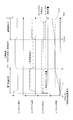
- FIG. 6 is an example of a timing chart for explaining the change over time from the low temperature startup operation to the normal operation of the fuel cell system 100 described above.
- the graph in FIG. 6A represents a change in stack voltage
- the graph in FIG. 6B represents a change in stack current.
- the graph of FIG.6 (c) represents the change of an anode gas supply flow rate and a cathode gas supply flow rate.
- the graph of FIG. 6D represents a change in the stack temperature Ts.
- the control unit 200 receives the ignition switch ON signal (start request for the fuel cell stack 1), and detects that the stack temperature Ts is lower than the low temperature start operation execution reference temperature Tth1 (Yes in step S100). And FIG. 6 (d)). As a result, the control unit 200 determines that the fuel cell system 100 is in a low temperature startup operation.
- the control unit 200 controls the cathode gas supply / exhaust device 2 such as the compressor 22 and the anode gas supply / exhaust device 3 such as the anode gas circulation blower 36 so as to execute the subzero start processing of the low temperature start operation.
- the supply of the anode gas and the cathode gas to 1 is started (see step S110, step S111, and FIG. 6C). Along with this, the stack voltage rises (FIG. 6A).
- the control unit 200 controls the power unit 52 to start taking out current from the fuel cell stack 1. That is, power generation of the fuel cell stack 1 according to the required load is started, and the stack current increases (see step S111 and FIG. 6B). Along with this, the stack voltage decreases (see FIG. 6A). The stack temperature Ts increases due to heat generated by the power generation of the fuel cell stack 1.
- the control unit 200 starts the above-described stack current reduction process as the recovery control (see step S112, step S113, and FIG. 6B).
- the actual anode gas supply flow rate is higher than the required anode gas supply flow rate even though the actual stack current is smaller than the load request current.
- the voltage rises see FIG. 6 (a)).
- the actual required anode gas supply flow rate (the target anode gas supply flow rate during the recovery control) is shifted to the recovery control from the start-up process below zero, but the load demand current itself is reduced. Is adjusted to the same value as the required anode gas supply flow rate during the sub-zero start-up process. That is, the anode gas supply flow rate is maintained without being changed even after the transition from the below-zero startup process to the stack current reduction process (see the solid line in FIG. 6C).
- the anode gas supply flow rate exceeds the required anode gas supply flow rate during the stack current reduction process (see the two-dot chain line in FIG. 6C).
- it is defined as the ratio of the actual anode gas supply flow rate to the anode gas supply flow rate required to realize the actual stack current (recovery control target output current).
- the anode gas stoichiometric ratio is increased.
- the water content of the anode catalyst layer 112A of the fuel cell stack 1 can be reduced by this stack current reduction process, and the water in the electrolyte membrane 111 between the anode catalyst layer 112A and the cathode catalyst layer 113A can be reduced.
- the concentration gradient can be increased, and moisture movement from the cathode catalyst layer 113A to the electrolyte membrane 111 can be promoted. Thereby, the water
- the cathode gas supply flow rate is set to a value that matches the anode gas supply flow rate. That is, the actual cathode gas supply flow rate is set higher than the cathode gas supply flow rate required to achieve the target output current during recovery control, and the cathode gas stoichiometric ratio is relatively increased. . However, the actual cathode gas supply flow rate may be adjusted to a lower value, for example, set to a value required for realizing the target output current during recovery control.
- the control unit 200 ends the recovery control at time t3, and shifts the fuel cell stack 1 to the normal operation (see step S114 and step S120). Specifically, the control unit 200 ends the stack current reduction process, and returns the target value of the stack current and the target value of the anode gas supply flow rate to the load request current and the required anode gas supply flow rate, respectively. Similarly, the cathode gas supply flow rate is set to the required cathode gas supply flow rate corresponding to the load requirement.
- the load demand current is controlled by basic output current control. Setting the target output current increases the stack current. As a result, the stack voltage decreases (see FIG. 6A).
- the anode gas supply flow rate and the cathode gas supply flow rate are adjusted so that the anode gas stoichiometric ratio and the cathode gas stoichiometric ratio are 1 or more in accordance with the load demand current according to the basic flow rate control. Is done.
- FIG. 7 is a diagram for explaining the operational effect of the recovery control of the present embodiment. Specifically, FIG. 7 schematically shows the configuration of the catalyst layers 112 ⁇ / b> A and 113 ⁇ / b> A and the electrolyte membrane 111 in the fuel cell 10.
- the cathode catalyst layer 113A contains moisture derived from the humidified portion of the moisture recovery device 25 or generated water of power generation.
- water derived from water generated by power generation is mainly contained in the cathode vacancies and the cathode electrolyte. If the moisture contained in the cathode vacancies is large, so-called flooding that inhibits gas diffusion in the cathode electrode 113 occurs, and the output performance of the fuel cell stack 1 may be degraded.
- the dry air is supplied to the cathode channel 131 to promote the evaporation of the moisture in the cathode vacancies, and the evaporated moisture is It was made to discharge in the flow path 131.
- the stack temperature Ts is low, the moisture present in the cathode vacancies is low, and the temperature of the supplied dry air is also low. Therefore, the vapor pressure of the water present in the cathode vacancies is low, and the saturated water vapor pressure of the dry air itself is also low, so the effect of evaporating the water is low.
- the molecules constituting the dry air are mainly nitrogen molecules, oxygen molecules, etc. and have a relatively large molecular weight, the diffusion effect in the cathode catalyst layer 113A is low. Therefore, even if dry air is supplied to the cathode channel 131, the dry air does not sufficiently reach the cathode vacancies, so that it is considered that the effect of removing moisture in the cathode vacancies is low.
- the present inventors As a result of diligent research, replaced the idea of discharging the moisture in the cathode holes to the cathode channel 131 as in the above-described dry air supply process, The inventors have arrived at a novel idea of removing moisture in the cathode vacancies by moving the moisture in the vacancies to the electrolyte membrane 111 side.
- the present inventors remove the water in the cathode pores from the cathode catalyst layer 113A to the electrolyte membrane 111 due to the difference in water concentration gradient between the anode catalyst layer 112A and the cathode catalyst layer 113A. Attention was focused on the de-diffusion phenomenon (see the bold arrow in FIG. 7), which is a phenomenon in which the moisture of the water moves.
- anode gas is supplied to the anode catalyst layer 112A via the anode flow path 121 and the gas diffusion layer 112B.
- the anode catalyst layer 112A contains some moisture derived from the moisture in the anode gas, it does not substantially contain water generated by power generation.
- the water in the anode vacancies of the anode catalyst layer 112A generally moves to the electrolyte membrane 111 side with the proton H + along with the electrochemical reaction of the fuel cell 10. Therefore, in the anode electrode 112, water is present substantially only in the anode electrolyte. That is, the moisture contained in the anode catalyst layer 112A is less than the moisture contained in the cathode catalyst layer 113A.
- a water concentration gradient is generated between the anode catalyst layer 112A and the cathode catalyst layer 113A due to the difference in moisture content between the anode catalyst layer 112A and the cathode catalyst layer 113A described above (see the one-dot chain line graph in FIG. 7).
- the concentration gradient of water in the present embodiment is given as a ratio of the amount of water contained in the cathode catalyst layer 113A to the amount of water contained in the anode catalyst layer 112A.
- the inventors pay attention to the reverse diffusion phenomenon, promote the reverse diffusion phenomenon in the low temperature startup operation of the fuel cell stack 1, and make the water concentration gradient in the low temperature startup operation more than the water concentration gradient in the normal operation operation.
- the idea has been reached that the moisture in the cathode vacancies is moved to the electrolyte membrane 111 side and efficiently removed.
- a process for reducing the water content in the anode 112 is executed. More specifically, the control unit 200 sets a target output current during recovery control that is lower than the load request current, and controls the power unit 52 so that the stack current approaches the target output current during recovery control during the recovery control. Stack current reduction processing (see step S113 in FIG. 5 and time t2 to time t3 in FIG. 6B) is executed.
- the actual anode gas supply flow rate becomes excessive with respect to the stack current. That is, the flow rate of the anode gas supplied from the anode flow path 121 to the anode catalyst layer 112A via the gas diffusion layer 112B becomes higher than the demand for power generation, and surplus anode gas remaining without being consumed in power generation is generated. Will increase. Therefore, the surplus anode gas diffuses into the anode electrolyte, so that moisture is removed from the anode electrolyte by the anode gas.
- the amount of water in the anode catalyst layer 112A decreases, so that the water concentration gradient between the anode catalyst layer 112A and the cathode catalyst layer 113A increases (see the solid line graph in FIG. 7). Therefore, the action of the despreading phenomenon is promoted.
- the diffusion effect in the anode catalyst layer 112A is higher than that of the cathode gas mainly containing nitrogen or oxygen.
- the anode catalyst layer 112A contains almost no moisture in the anode vacancies as described above, the anode gas diffuses in the anode vacancies without being inhibited by moisture.
- the anode gas is highly effective in diffusing into the anode electrolyte, and moisture in the anode electrolyte can be efficiently removed.
- the amount of moisture contained in the anode catalyst layer 112A is originally smaller than the amount of moisture contained in the cathode catalyst layer 113A. Therefore, the removal of moisture in the anode electrolyte by the recovery control can be performed relatively more effectively than when moisture in the cathode catalyst layer 113A is removed.
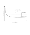
- FIG. 8 shows the amount of moisture transferred from the cathode catalyst layer 113A to the electrolyte membrane 111 according to the stack temperature Ts (hereinafter also referred to as “moved moisture amount Wm”) and evaporation from the cathode catalyst layer 113A to the cathode channel 131. It is a graph explaining the relationship of the moisture content (it is hereafter described also as “evaporation moisture amount Wc").
- the horizontal axis represents the stack temperature Ts
- the vertical axis represents the dimensionless amount defined by (Wm ⁇ Wc) / Wc. That is, the value on the vertical axis is a value representing how much the moving water amount Wm is larger than the evaporated water amount Wc.
- the region where the vertical axis> 0 in the graph of FIG. 8 is a region where the moving water amount Wm is larger than the evaporated water amount Wc (hereinafter also referred to as “water movement dominant region”). . Therefore, in this water movement dominant region, water movement from the cathode catalyst layer 113A to the electrolyte membrane 111 is more dominant than water evaporation from the cathode catalyst layer 113A to the cathode channel 131.
- the moving water amount Wm and the evaporated water amount Wc are the same.
- the amount of water transferred from the cathode catalyst layer 113A to the electrolyte membrane 111 and the amount of water evaporation from the cathode catalyst layer 113A to the cathode channel 131 are substantially equal.
- the stack temperature Ts> T1 is the flow path evaporation dominant region
- the stack temperature Ts ⁇ T1 is the water transfer dominant region.
- the value of T1 is a value in the vicinity of 25 ° C. although there is a slight range depending on experimental conditions and the like. Therefore, the following description will be made assuming that T1 ⁇ 25 ° C.
- the region where the stack temperature Ts ⁇ 25 ° C. is assumed as the execution environment for the low-temperature startup operation is the water transfer dominant region. Therefore, in order to obtain a water removal effect comparable to the recovery control of the present embodiment by the conventional dry air supply process, it is necessary to raise the stack temperature Ts to 25 ° C. at least. However, in order to raise the stack temperature Ts to this point, it takes a considerable time even if heating is performed using a heater or the like in addition to the heat generated by the power generation of the fuel cell stack 1.
- the cathode catalyst layer 113A since the region where the stack temperature Ts ⁇ 25 ° C. in the execution environment of the low-temperature start-up operation is in the water transfer dominant region, the cathode catalyst layer 113A according to the recovery control of the present embodiment is used as the electrolyte.
- the water movement to the membrane 111 can realize the water removal from the cathode catalyst layer 113A which is clearly more effective than the water discharge by the evaporation to the cathode channel 131.
- the present inventors pay attention to the reverse diffusion phenomenon, which is a phenomenon in which water moves from the cathode catalyst layer 113A to the electrolyte membrane 111, and the water movement due to the reverse diffusion phenomenon occurs in the cathode channel in a low temperature environment. It has been found that it is superior to the discharge of moisture by evaporation to 131.
- the present inventors have increased the concentration gradient of the water in the electrolyte membrane by the recovery control of this embodiment, thereby promoting the reverse diffusion phenomenon even in a low temperature environment.
- the cathode catalyst The inventors have come up with an epoch-making idea that the removal of moisture from the layer 113A can be performed more efficiently than the conventional method, and can contribute to the efficient recovery of the output performance of the fuel cell stack 1.
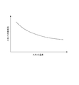
- FIG. 9 shows a graph for explaining the recovery effect of the output performance by the recovery control of this embodiment. Specifically, FIG. 9 shows the time change of the cell voltage during the cold start operation.
- the broken line graph in FIG. 9 represents a change in the cell voltage when the recovery control of the present embodiment is not executed.
- the solid line graph of FIG. 9 represents a change in the cell voltage when the recovery control of this embodiment is executed.
- the recovery control of the present embodiment is a process for making the actual anode gas supply flow rate equal to or higher than the required anode gas flow rate while reducing the stack current. Therefore, as apparent from FIG. 9, the cell voltage of the solid line graph during the recovery control is higher than that of the broken line graph in which the recovery control is not executed.
- the operation shifts to the normal operation of the fuel cell stack 1.
- the cell voltage when the recovery control is executed is controlled even though the load request current of the normal operation operation is controlled as the target output current, It is clearly higher than the cell voltage when the recovery control is not executed. That is, this indicates that the output performance of the fuel cell stack 1 has been recovered by the recovery control of the present embodiment.
- the fuel cell system 100 according to the present embodiment described above has the following operational effects.
- the fuel cell system 100 of the present embodiment includes an electrolyte membrane 111 having catalyst layers 112A and 113A on both sides of an anode electrode and a cathode electrode, an anode channel 121 for supplying an anode gas as a fuel gas to the anode electrode side, a cathode
- the fuel cell stack 1 is formed by stacking a plurality of fuel cells 10 as a single cell, and a cathode channel 131 for supplying a cathode gas as an oxidizing gas on the pole side.
- the fuel cell system 100 includes an anode gas supply / discharge device 3 as a fuel gas adjusting device that adjusts the anode gas in the anode flow channel 121 and a cathode gas as an oxidizing gas adjusting device that adjusts the cathode gas in the cathode flow channel 131.
- a supply / discharge device 2 and an anode gas supply / discharge device 3 and a control unit 200 for controlling the cathode gas supply / discharge device 2 in accordance with the state of the fuel cell stack 1 (load required current and the like) are provided.
- control unit 200 is an operation determination unit that determines whether the operation is a cold start operation (low temperature start operation) or a normal operation (normal operation operation), and the operation determination unit performs a low temperature start operation. Is determined (when the IGN ON signal is received), the concentration gradient adjusting device functions as a recovery control unit that executes recovery control for increasing the concentration gradient of water in the electrolyte membrane 111 from that of the normal operation (see FIG. 5 step S113 and FIG. 7).
- the moisture in the cathode catalyst layer 113A is moved to the electrolyte membrane 111 when the fuel cell stack 1 is started at a low temperature by the recovery control.
- the water concentration contained in the cathode catalyst layer 113A is increased by increasing the water concentration gradient in the electrolyte membrane 111 from the water concentration gradient in the normal operation operation by the recovery control performed during the low temperature startup operation. It can be removed by moving to the electrolyte membrane 111 side.
- the moisture contained in the cathode catalyst layer 113A is removed from the electrolyte membrane 111.
- the output performance of the fuel cell stack 1 can be recovered by removing it by the method of moving to the side.
- the temperature region in the low temperature environment is such that the moisture movement (back diffusion phenomenon) from the cathode catalyst layer 113A to the electrolyte membrane 111 is caused by the cathode flow due to the evaporation of moisture in the cathode catalyst layer 113A. It belongs to the water movement dominant region which is superior to the discharge to the channel 131. Therefore, the moisture in the cathode catalyst layer 113A can be more effectively removed by performing the recovery control during the low temperature startup operation performed in a low temperature environment to promote the reverse diffusion phenomenon.
- the moisture in the cathode catalyst layer 113A is effectively removed without raising the ambient environment temperature such as the stack temperature to a high temperature as required in the conventional dry air treatment. Can be removed. Therefore, it is possible to recover the output performance of the fuel cell stack 1 to a desired performance while shortening the time of the low temperature startup operation including the subzero startup processing and the recovery control.
- the concentration gradient adjusting device has a power unit 52 as an output current adjusting device that adjusts a stack current that is an output current of the fuel cell stack 1.
- the control unit 200 as the recovery control unit increases the concentration gradient of water in the electrolyte membrane 111 by causing the power unit 52 to reduce the stack current to be lower than the required output current (load required current) based on the required load. (See time t2 to time t3 in FIG. 6B and FIG. 7).
- the anode gas supply flow rate required for realizing the reduced stack current is reduced. Therefore, the actual anode gas supply flow rate (target anode gas supply flow rate during recovery control) is excessive with respect to the anode gas supply flow rate required for realizing the stack current. As a result, in the recovery control, the anode gas stoichiometry increases as compared to during normal startup operation.
- the flow rate of the anode gas supplied from the anode flow path 121 to the anode catalyst layer 112A via the gas diffusion layer 112B becomes excessive with respect to the theoretical amount consumed in power generation, and remains in the anode catalyst layer 112A.
- the anode gas flow rate increases.
- surplus anode gas diffuses into the anode electrolyte, which facilitates the removal of moisture from the anode electrolyte by the anode gas.
- the main component of the anode gas is hydrogen having a small molecular weight
- the diffusion effect is higher than that of the cathode gas mainly containing nitrogen or oxygen.
- the anode catalyst layer 112A contains almost no moisture in the anode vacancies, the anode gas diffuses in the anode vacancies without being inhibited. Therefore, the moisture in the anode electrolyte is more suitably removed by the recovery control.
- the amount of water in the anode catalyst layer 112A is further reduced, and an increase in the concentration gradient of water between the anode catalyst layer 112A and the cathode catalyst layer 113A is further promoted (see the solid line graph in FIG. 7). Therefore, moisture movement (back diffusion phenomenon) from the cathode catalyst layer 113A to the electrolyte membrane 111 is further promoted.
- the stack current is reduced below the load request current as described above, so that the actual power generation amount of the fuel cell stack 1 is smaller than the power generation amount of the fuel cell stack 1 according to the load request. Lower. Therefore, generation of generated water due to power generation is suppressed. That is, since accumulation of generated water in the cathode catalyst layer 113A is suppressed, moisture can be removed from the cathode catalyst layer 113A more quickly in the recovery control, which contributes to further shortening of the time for the low temperature startup operation. It becomes.
- the control unit 200 determines whether the operation is a low temperature start operation or a normal operation operation, and the low temperature start operation is performed. Is determined (when an IGN ON signal is received), the recovery control for increasing the water concentration gradient in the electrolyte membrane 111 of the fuel cell 10 as a fuel cell over the water concentration gradient in the normal operation operation. Is executed (step S113 in FIG. 5).
- the moisture contained in the cathode catalyst layer 113A is moved to the electrolyte membrane 111 side.
- the moisture in the cathode electrode 113 can be more effectively removed without raising the temperature of the fuel cell stack 1 to a high temperature as required in the conventional dry air treatment. Therefore, the output performance of the fuel cell stack 1 is restored to a desired performance, and the time for the low temperature startup operation can be shortened.
- the recovery control is executed after the start-up process below zero (after the temperature rise of the fuel cell stack 1) has been described.
- the recovery control is performed during the start-up process below zero (while the temperature rise of the fuel cell stack 1) May be executed.
- the actual anode gas supply flow rate (recovery control target anode gas supply flow rate) is adjusted to the same value as the required anode gas supply flow rate during the subzero start-up process. Is explained. That is, in this example, the actual anode gas supply flow rate (target anode gas supply flow rate during recovery control) is set larger than the required anode gas supply flow rate during recovery control.
- the actual anode gas supply flow rate (target anode gas supply flow rate during recovery control) may be set to the same value as the required anode gas supply flow rate during recovery control (see the two-dot chain line in FIG. 6C). . That is, during the recovery control in the present embodiment, the anode gas supply flow rate is controlled to be adjusted to the required anode gas supply flow rate during the recovery control according to the normal flow rate control, and only the stack current is lower than the load required current. May be set. Even in this case, since the state in which the anode gas flow rate becomes excessive in the anode catalyst layer 112A can be realized, the effect of removing the moisture in the anode catalyst layer 112A already described can be obtained.
- control unit 200 functioning as a recovery control unit sets the stack current during recovery control to substantially zero.
- FIG. 10 is an example of a timing chart for explaining a change over time from the low temperature start operation to the normal operation of the fuel cell system 100 in the present embodiment.
- the graph of Fig.10 (a) represents the change of stack voltage
- the graph of FIG.10 (b) represents the change of stack current.
- the graph of FIG.10 (c) represents the change of an anode gas supply flow rate and a cathode gas supply flow rate.
- the graph of FIG. 10D represents a change in the stack temperature Ts.
- the control unit 200 sets the target output current at the time of recovery control of the fuel cell stack 1 to substantially zero at the time t2 when the recovery control is started, and the stack current is set to this value during the recovery control.
- a stack current reduction process (see time t2 to time t3 in FIG. 10B) is executed to control the power unit 52 so as to approach the target output current during recovery control. That is, the stack current is set to substantially zero.
- the shortage of the power supply to the load that may occur due to the limitation of the current extraction from the fuel cell stack 1 is compensated by the power of a battery (not shown) as in the first embodiment.
- control unit 200 adjusts the anode gas supply flow rate (target anode gas supply flow rate during recovery control) to the same value as the requested anode gas supply flow rate during the sub-zero start-up process, as in the first embodiment.
- the actual anode gas supply flow rate during the stack current reduction process exceeds the required anode gas supply flow rate during the stack current reduction process (see the two-dot chain line in FIG. 6C). That is, when the start-up process below zero shifts to the stack current reduction process, the anode gas stoichiometric ratio increases.
- the fuel cell system 100 according to the present embodiment described above has the following operational effects.
- control unit 200 as the recovery control unit sets the stack current to substantially zero by the power unit 52 (see time t2 to time t3 in FIG. 10C).
- the anode gas supply flow rate required to realize the actual stack current is substantially zero. Therefore, it is defined as the ratio of the actual anode gas supply flow rate (target anode gas supply flow rate during recovery control) to the anode gas supply flow rate required to realize the actual stack current (recovery control target output current).
- the anode gas stoichiometric ratio will increase as compared with the anode gas stoichiometric ratio in the normal operation operation or the like, no matter how the actual anode gas supply flow rate is set.
- the fuel cell stack 1 is not substantially in power generation. Therefore, the generation of generated water in the cathode catalyst layer 113A during the recovery control can be made substantially zero. That is, since the generation of new moisture in the cathode catalyst layer 113A is further suppressed, the effect of recovery control for the purpose of removing moisture from the cathode catalyst layer 113A is further improved.
- the anode gas stoichiometric ratio is defined as the actual anode gas supply flow rate with respect to the anode gas supply flow rate required to realize the actual stack current. Therefore, if the actual stack current is substantially zero, and the anode gas supply flow rate required to achieve the stack current is substantially zero, then the theoretical anode gas supply flow rate is theoretically zero.
- the anode gas stoichiometric ratio takes a value that greatly exceeds 1.
- the anode gas stoichiometric ratio can be maintained at a value higher than 1.
- the actual anode gas supply flow rate is substantially reduced.
- the required anode gas supply flow rate during the recovery control may be lowered within a range not becoming zero.
- the target anode gas supply flow rate during recovery control is set to the same value as the requested anode gas supply flow rate, and the load requirement itself is reduced, as in the normal control logic for the anode gas supply flow rate.
- the actual anode gas supply flow rate may be controlled to be decreased by reducing the required anode gas supply flow rate itself during the recovery control.
- the anode gas consumption during the recovery control can be reduced while ensuring the effect of promoting the moisture movement from the cathode catalyst layer 113A to the electrolyte membrane 111 during the low temperature startup operation.
- the control unit 200 as the recovery control unit controls the anode gas supply / discharge device 3 to increase the anode gas supply flow rate during the recovery control to be higher than the required anode gas supply flow rate. Increase the concentration gradient of 111 water.
- FIG. 11 is an example of a timing chart for explaining a change with time from a low-temperature startup operation to a normal operation of the fuel cell system 100 in the present embodiment.
- the graph of FIG. 11A represents the change of the stack voltage
- the graph of FIG. 11B represents the change of the stack current.
- the graph of FIG.11 (c) represents the change of an anode gas supply flow rate and a cathode gas supply flow rate.
- the graph of FIG. 11D represents a change in the stack temperature Ts.
- control unit 200 uses the anode gas supply flow rate as the required anode gas supply flow rate (see the broken line in FIG. 11C) instead of the stack current reduction process for reducing the stack current as the recovery control.
- the anode gas supply flow rate increasing process for increasing the time is executed (see time t2 to time t3 in FIG. 11C).
- control unit 200 shifts from the below-zero start-up process to the recovery control, as the anode gas supply flow rate increase process, the control unit 200 sets a recovery control target anode gas supply flow rate that is higher than the required anode gas supply flow rate.
- the anode gas supply / discharge device 3 is controlled so that the gas supply flow rate approaches the target anode gas supply flow rate during recovery control.
- the control unit 200 maintains the load demand current due to the load and maintains the stack current even after shifting from the below-zero startup process to the recovery control (see time t2 to time t3). That is, the required load is made the same during the below-zero startup process and during the recovery control, and the control unit 200 sets the recovery control target output current to the same value as the load required current based on this required load.
- the anode gas stoichiometric ratio increases.
- the anode gas stoichiometric ratio can be increased while maintaining the state where the required power of the load is satisfied by the power generation of the fuel cell stack 1 without using the power of the battery or the like.
- the anode gas is adjusted so as to match the stack current with the relatively low load demand current at the beginning of the normal operation.
- the supply flow rate is further reduced compared to the case of the first embodiment.
- the fuel cell system 100 according to the present embodiment described above has the following operational effects.
- the concentration gradient adjusting device includes an anode gas supply / discharge device 3 as a fuel gas adjusting device. Then, the control unit 200 as the recovery control unit increases the anode gas supply flow rate by the anode gas supply / exhaust device 3 more than the required anode gas supply flow rate based on the required load, so that the concentration gradient of water in the electrolyte membrane 111 is increased. (See time t2 to time t3 in FIG. 11C and FIG. 7).
- the anode gas stoichiometric ratio is increased by increasing the anode gas supply flow rate without changing the stack current in the process of transitioning from below-zero start-up processing to recovery control (see time t2 in FIG. 11). ing.
- the present invention is not limited to this.
- the load request current in the recovery control is decreased with respect to the load request current in the sub-zero startup process, and the target output current during the recovery control is set to the recovery control. It may be set to the same value as the required load current. That is, the stack current may be decreased in accordance with the decrease in the load request current when shifting from the below-zero startup process to the recovery control.
- the actual anode gas supply flow rate during recovery control (target anode gas supply flow rate during recovery control) ) Is higher than the required anode gas supply flow rate during the recovery control, so that an increase in the anode gas stoichiometric ratio is realized.
- the stack current may be set lower than the load required current while maintaining the anode gas supply flow rate higher than the required anode gas supply flow rate. That is, as the recovery control, the stack current reduction process of the first embodiment and the anode gas supply flow rate increase process of the present embodiment may be combined. Thereby, the anode gas stoichiometric ratio can be increased more effectively during the recovery control, and the moisture transfer effect from the cathode catalyst layer 113A to the electrolyte membrane 111 can be further enhanced.
- control unit 200 in this embodiment functions as a recovery control end determination unit that determines the end time of the recovery control (stack current reduction process) described in step S113 and ends the recovery control when the end time is reached. .
- the cathode gas increase / decrease process to be increased after decreasing the cathode gas supply flow rate during the recovery control is executed a plurality of times, and the recovery control is completed based on the behavior of the cell voltage during the cathode gas increase / decrease process. Make a timing decision.
- the target cathode gas supply flow rate during recovery control is set as the target value of the cathode gas supply flow rate instead of the required cathode gas supply flow rate based on the load required current.
- the control unit 200 causes the compressor 22 of the cathode gas supply / discharge device 2 so that the detected value of the cathode gas supply flow rate obtained by the air flow meter 23 approaches the target cathode gas supply flow rate during the recovery control. Control the output of
- FIG. 12 is a flowchart for explaining the flow of the cold start operation of the present embodiment.
- the control unit 200 executes the processes of Steps S111 to S113 as in the first embodiment.
- control unit 200 performs the cathode gas increase / decrease process in step S214 instead of determining whether or not the duration tre of the stack current reduction process in step S114 (see FIG. 5) of the first embodiment is greater than the predetermined time tb. And the end time judgment of the recovery control in step S215 is executed.
- the control unit 200 adjusts the recovery control target cathode gas supply flow rate to the recovery control target anode gas supply flow rate (hereinafter referred to as “anode gas consumption”).
- the output of the compressor 22 is increased or decreased so as to switch between “theoretical cathode gas supply flow rate” and zero.
- the cathode gas supply flow rate increases or decreases in the cathode gas increase / decrease process during the recovery control.
- control unit 200 sets the cathode gas stoichiometric ratio when the recovery control target cathode gas supply flow rate is set to zero, that is, when the cathode gas supply flow rate is decreased in the cathode gas increase / decrease process. So that the output of the compressor 22 is reduced to 1 or less.
- the cathode gas stoichiometric ratio is defined as the ratio of the actual cathode gas supply flow rate (corresponding to zero or the anode gas consumption theoretical cathode gas supply flow rate) to the required cathode gas supply flow rate based on the load required current.
- the recovery gas control target cathode gas supply flow rate is set to the anode gas consumption theoretical cathode gas supply flow rate
- the recovery gas control target cathode gas supply flow rate is set to zero while the cathode gas stoichiometric ratio exceeds 1.
- the cathode gas stoichiometric ratio is 1 or less. That is, the control unit 200 increases or decreases the cathode gas supply flow rate so that the cathode gas stoichiometric ratio exceeds 1 in the cathode gas increase / decrease process.
- step S215 the control unit 200 switches the target cathode gas supply flow rate during the recovery control from zero to the anode gas consumption theoretical cathode gas supply flow rate to determine the end time of the recovery control, and the output of the compressor 22 is increased. It is determined whether or not the change amount ⁇ Vcell of the cell voltage during the predetermined time ⁇ t during the increase operation of the cathode gas supply flow rate is greater than the threshold value ⁇ .
- control unit 200 continuously acquires a plurality of cell voltage detection values by the current / voltage measurement unit 50 when the cathode gas supply flow rate increases during the cathode gas increase / decrease process, and stores them in a memory or the like. Further, the control unit 200 extracts a plurality of cell voltage detection values when the cathode gas supply flow rate is increasing during the cathode gas increase / decrease process from the memory, and calculates a change amount ⁇ Vcell of the cell voltage detection values during the time ⁇ t.
- control unit 200 determines that the cell voltage change amount ⁇ Vcell is greater than the predetermined threshold value ⁇ , the control unit 200 determines that the output performance of the fuel cell stack 1 has recovered to a desired region, and performs stack control as recovery control. The voltage drop process is terminated (that is, shifts to normal operation).
- control unit 200 determines that the cell voltage change amount ⁇ Vcell is not greater than the predetermined threshold value ⁇ , the control unit 200 determines that the output performance of the fuel cell stack 1 has not reached the desired level, and continues to step S113.
- the stack voltage lowering process, the cathode gas increase / decrease process in step S214, and the determination in step S215 are repeated.
- FIG. 13 is an example of a timing chart for explaining the change over time from the low temperature startup operation to the normal operation of the fuel cell system 100 of the present embodiment.
- the graph in FIG. 13A represents the change in the stack voltage
- the graph in FIG. 13B represents the change in the stack current.
- the graph of FIG.13 (c) represents the change of an anode gas supply flow rate and a cathode gas supply flow rate.
- the graph of FIG. 13D represents a change in the stack temperature Ts.
- the cathode gas increase / decrease process is started at a time td when a predetermined time has elapsed from the time t2 at which the recovery control is started (see FIG. 13C).
- the cathode gas increasing / decreasing process is executed three times with the operation of increasing the cathode gas supply flow rate after decreasing it as one cycle.
- the control unit 200 increases or decreases the cathode gas supply flow rate so that the cathode gas stoichiometric ratio exceeds 1, as described above. Therefore, the cathode gas supply flow rate to the fuel cell stack 1 is increased. The state which is insufficient with respect to the request
- control unit 200 determines that the change amount ⁇ Vcell of the cell voltage when the cathode gas supply flow rate is increasing during the cathode gas increase / decrease process is larger than the predetermined threshold value ⁇ , the control unit 200 Shift to normal operation.
- FIG. 14 is a graph showing the difference in time variation of the cell voltage before and after the recovery of the output performance of the fuel cell stack 1 in this embodiment. More specifically, FIG. 14 shows a case where the cathode gas increase / decrease processing is executed for each of the fuel cell stack 1 not performing the recovery control and the fuel cell stack 1 after the recovery control is executed. The time change of each cell voltage when the supply flow rate increases is shown.
- the alternate long and short dash line graph shows the time change of the cell voltage when the recovery control is not performed on the fuel cell stack 1 and the cathode catalyst layer 113A contains moisture and the output performance is relatively low. Is shown. Further, the solid line graph of FIG. 14 shows the time change of the cell voltage after executing the recovery control of the present embodiment.
- the cell voltage change amount ⁇ Vcell for the predetermined time ⁇ t exceeds the threshold value ⁇ , whereas when the recovery control is not performed, the threshold value is obtained. It is below ⁇ . That is, when the recovery control is executed, the rate of increase (rise rate) of the cell voltage at a predetermined time ⁇ t after the start of the increase in the cathode gas supply flow rate is increased.
- the fuel cell system 100 according to the present embodiment described above has the following operational effects.
- the control unit 200 as the recovery control unit determines whether or not it is the end time of the recovery control (step S215 in FIG. 12), and determines that it is the end time of the recovery control. , Functioning as a recovery control end determination unit that ends the recovery control (Yes in step S215 in FIG. 12).
- the recovery control can be terminated at the timing when the output performance of the fuel cell stack 1 recovers to a desired region, and the recovery control is continued even though the output performance of the fuel cell stack 1 is recovered. Can be suppressed. As a result, it contributes to shortening the time for the low temperature start-up operation.
- the fuel cell system 100 of the present embodiment further includes a current / voltage measurement unit 50 that is an output voltage detection unit that detects a cell voltage as an output voltage of the fuel cell.
- the control unit 200 as a recovery control end determination unit controls the cathode gas supply / exhaust device 2 during the recovery control to increase the oxidizing gas increase / decrease process after decreasing the cathode gas supply flow rate to the fuel cell stack 1.
- the cathode gas increase / decrease process (step S214 in FIG. 12) is executed at least once, and the end time of the recovery control is determined based on the behavior of the cell voltage during the cathode gas increase / decrease process (step S215 in FIG. 12).
- the timing at which the output performance of the fuel cell stack 1 recovers and the actual end timing of the recovery control are more reliably determined. Can be adapted. As a result, while the output performance of the fuel cell stack 1 is more reliably recovered, the continuation of useless recovery control is more reliably prevented, thereby contributing to shortening the time of the low-temperature start-up operation.
- the control unit 200 as the recovery control end determination unit performs a required oxidizing gas supply flow rate (based on a required load) during a decrease operation of the cathode gas supply flow rate in the cathode gas increase / decrease process
- the cathode gas supply / discharge device 2 is controlled so that the cathode gas stoichiometric ratio, which is the ratio of the cathode gas supply flow rate to the required cathode gas supply flow rate), is 1 or less.
- the operation of reducing the cathode gas supply flow rate during the cathode gas increase / decrease process can cause a state where the cathode gas supply flow rate is insufficient with respect to the power generation requirement, thereby reducing the cell voltage more reliably. Therefore, when an operation for increasing the cathode gas supply flow rate is performed after the operation for decreasing the cathode gas supply flow rate, a change in the cell voltage can be detected more reliably, and the determination accuracy of the end timing of the recovery control can be improved. Will be improved.
- control unit 200 serving as the recovery control end determination unit is configured to increase the cell voltage within a predetermined time ⁇ t during a cathode gas supply flow increase operation during the cathode gas increase / decrease process.
- ⁇ it is determined that it is the end time of the recovery control (step S215 in FIG. 12 and FIG. 14).
- the threshold value ⁇ can be set as appropriate according to the situation, but the lower limit value of the cell voltage change amount ⁇ Vcell determined from the viewpoint of whether the output performance of the fuel cell stack 1 has recovered to a desired region. Is preferably the threshold ⁇ .
- the example which performs the cathode gas increase / decrease process 3 times is shown in the time chart of FIG. 13, as long as the frequency
- the recovery control end time may be determined by determining the stack voltage change amount during a predetermined time ⁇ t and the predetermined threshold value.
- the cathode stoichiometric ratio is increased or decreased over 1 in the cathode gas increase / decrease process, and the cell voltage change amount ⁇ Vcell associated therewith is calculated.
- the cell supply change ⁇ Vcell may be calculated by increasing / decreasing the stack current in a predetermined cycle without changing the cathode supply flow rate itself.
- the determination of the end time of the recovery control another determination method may be adopted instead of determining that the end time of the recovery control when the cell voltage change amount ⁇ Vcell is larger than the threshold value ⁇ .
- the relationship between the degree of recovery of the output performance of the fuel cell stack 1 and the increase in the stack temperature Ts is recorded in advance as a table, and the end time of the recovery control is determined from the stack temperature Ts based on the table. Also good.
- FIG. 15 is a flowchart for explaining the flow of the cold start operation of the present embodiment.
- the control unit 200 executes the processing of steps S111 to S113 as in the first embodiment, and executes the cathode gas increase / decrease processing of step S214 as in the fourth embodiment.
- control unit 200 performs a size determination between the cell voltage differential value DVcell and the predetermined threshold value ⁇ in step S215 ′.
- control unit 200 acquires detection values of a plurality of cell voltages detected according to the measurement cycle of the current / voltage measurement unit 50 during the recovery control, and stores them in a memory or the like. Then, the control unit 200 divides the difference between the two cell voltage detection values in the adjacent measurement periods by the measurement time during the increase operation of the cathode gas supply flow rate during the cathode gas increase / decrease process. Calculate DVcell.
- control unit 200 determines the magnitude of the cell voltage differential value DVcell and the predetermined threshold value ⁇ .
- the control unit 200 determines that the cell voltage differential value DVcell is larger than the predetermined threshold value ⁇ , it is assumed that the output performance of the fuel cell stack 1 has recovered to a desired region, and stack voltage reduction processing as recovery control is performed. Terminate (ie transition to normal operation operation).
- control unit 200 determines that the cell voltage differential value DVcell is not larger than the threshold value ⁇ , it is determined that the output performance of the fuel cell stack 1 has not reached the desired region, and the stack voltage lowering process in step S113 is continued.
- the cathode gas increase / decrease process in step S214 and the determination in step S215 ′ are repeated.
- FIG. 16 is a graph showing the time change of the cell voltage differential value DVcell before and after the recovery of the output performance of the fuel cell stack 1 in the present embodiment. More specifically, FIG. 16 shows a cell at the time when the cathode gas supply flow rate of the cathode gas increase / decrease process is increased for each of the fuel cell stack 1 that is not performing the recovery control and the fuel cell stack 1 after the recovery control is executed. The time change of the voltage differential value DVcell is shown.
- the alternate long and short dash line graph shows the time change of the cell voltage differential value DVcell before performing the recovery control on the fuel cell stack 1.
- the solid line graph of FIG. 16 has shown the time change of the cell voltage differential value DVcell after performing the recovery control of this embodiment.
- the cell voltage differential value DVcell when the cathode gas supply flow rate is increased is clearly higher than when the recovery control is not performed. .
- the cell voltage differential value DVcell when the recovery control is not performed is significantly lower than the threshold value ⁇ , but exceeds the threshold value ⁇ after executing the recovery control. Therefore, it can be said that the cell voltage differential value DVcell more clearly reflects information on whether or not the output performance of the fuel cell stack 1 has been recovered.
- the output performance of the fuel cell stack 1 is recovered by determining that the recovery control is finished. And the actual end timing of the recovery control can be matched more reliably.
- the fuel cell system 100 according to the present embodiment described above has the following operational effects.
- the control unit 200 as the recovery control end determination unit is a time differential value of the cell voltage at the time of increasing the cathode gas supply flow rate as the behavior of the cell voltage during the cathode gas increase / decrease process.
- the cell voltage differential value DVcell is calculated, and when the cell voltage differential value DVcell is larger than a threshold value ⁇ as a predetermined value, it is determined that the recovery control is finished (Yes in step S215 ′ in FIG. 15).
- the end timing of the recovery control is determined based on the cell voltage differential value DVcell in which the information on the degree of recovery of the output performance of the fuel cell stack 1 clearly appears. It is possible to more reliably match the recovery timing and the actual recovery control end timing. Further, the calculation itself of the cell voltage differential value DVcell is simple, and the processing load of the control unit 200 is reduced.
- the stack water content Wst which is the water content in the fuel cell stack 1
- Rst which is the internal resistance of the fuel cell stack 1
- the estimated stack content is included. Based on the water amount Wst, it is determined whether or not the recovery control is to be executed.
- the stack water content Wst means the total water content contained in the elements constituting the fuel cell stack 1 such as the anode electrode 112, the cathode electrode 113, and the electrolyte membrane 111.
- FIG. 17 is a diagram showing a configuration of the fuel cell system 100 according to the sixth embodiment. As shown in the figure, the fuel cell system 100 of the present embodiment has an internal resistance measuring device 6 that measures the internal resistance of the fuel cell stack 1.
- the internal resistance measuring device 6 is connected to the fuel cell stack 1.
- the internal resistance measuring device 6 measures the internal impedance of the fuel cell stack 1 based on an appropriate measurement frequency, and detects this as the stack internal resistance Rst.
- the internal resistance measuring device 6 transmits the detected stack internal resistance Rst to the control unit 200.
- FIG. 18 shows a graph showing the relationship between the stack internal resistance Rst and the stack water content Wst. As can be understood from the figure, generally, there is a relationship between the stack internal resistance Rst and the stack water content Wst that the higher the stack internal resistance Rst, the lower the stack water content Wst.
- the control unit 200 of this embodiment stores the relationship between the stack internal resistance Rst and the stack water content Wst represented by the graph in a memory or the like in advance. Based on this relationship, the control unit 200 estimates the stack water content Wst from the stack internal resistance Rst received from the internal resistance measurement device 6.
- control unit 200 preliminarily sets a lower limit value of the stack water content Wst to an allowable level that does not substantially affect the output performance of the fuel cell stack 1 as the recovery control execution threshold value ⁇ . deep. Then, based on the magnitude relationship between the stack water content Wst calculated from the stack internal resistance Rst and the recovery control execution threshold ⁇ , it is determined whether or not to execute the recovery control.
- FIG. 19 is a flowchart for explaining the flow of the cold start operation of the present embodiment. As shown in the figure, the control unit 200 executes the processes of steps S111 to S112 as in the first embodiment.
- control unit 200 determines in step S112 that the stack temperature Ts is higher than the recovery control execution reference temperature Tth2, the control unit 200 determines whether or not to execute recovery control in step S613.
- step S613 the control unit 200 calculates the stack water content Wst from the stack internal resistance Rst, and compares the stack water content Wst with the recovery control execution threshold ⁇ .
- the control unit 200 determines that the recovery control needs to be executed, and executes the processes after step S113.
- the recovery control execution threshold value ⁇ when the calculated stack water content Wst is less than or equal to the recovery control execution threshold value ⁇ , it is determined that the recovery control is not necessary, and the low temperature startup operation is terminated. That is, in this case, only the sub-zero startup process (thawing operation) is executed as the low temperature startup operation.
- the fuel cell system 100 according to the present embodiment described above has the following operational effects.
- the control unit 200 serving as a recovery control unit estimates the moisture content Wst in the fuel cell that estimates the moisture content Wst that is the moisture content of the fuel cell stack 1 (step S613 in FIG. 19).
- the estimated stack water content Wst is larger than the recovery control execution threshold ⁇ as a predetermined value, it functions as a recovery control execution determination unit (Yes in step S613 in FIG. 19).
- the output performance of the fuel cell stack 1 may be affected.
- Recovery control can be performed.
- the stack water content Wst is relatively low and it is considered that the output performance of the fuel cell stack 1 is not affected or is small even if the recovery control is not executed, the low temperature start-up is performed without executing the recovery control. The operation can be terminated. Therefore, while it is possible to accurately determine and execute the situation where the recovery control is required, if the recovery control is unnecessary, this is not executed, which contributes to shortening the time of the cold start operation. be able to.
- the fuel cell system 100 of the present embodiment further includes an internal resistance measuring device 6 as an internal resistance detection unit that detects a stack internal resistance Rst that is an internal resistance of the fuel cell stack 1. Then, the control unit 200 as the fuel cell moisture content estimation unit estimates the stack moisture content Wst based on the stack internal resistance Rst.
- the stack water content Wst is estimated based on the stack internal resistance Rst showing a strong correlation with the stack water content Wst and used for the determination of the recovery control execution, it is easy to determine whether or not to execute the recovery control. It can be performed with higher accuracy by calculation.
- the stack water content Wst is estimated from the stack internal resistance Rst.
- the present invention is not limited to this example.
- other arbitrary parameters such as the cathode gas supply pressure and the cathode gas supply flow rate are used. Based on this, the stack water content Wst may be estimated.
- the measurement frequency of the internal impedance regarded as the stack internal resistance Rst in this embodiment suitably correlates with the moisture contained in the anode electrode 112, the cathode electrode 113, and the electrolyte membrane 111 in the fuel cell stack 1.
- the frequency band to be selected is preferably selected.
- the stack internal resistance Rst based on the internal impedance measured at the selected frequency is correlated with high accuracy by the amount of moisture in the cathode catalyst layer 113A that greatly affects the output performance of the fuel cell stack 1. .
- HFR High Frequency Resistance
- FIG. 20 is a graph showing the relationship between the stack temperature Ts and the stack internal resistance Rst. As understood from the figure, there is generally a relation between the stack temperature Ts and the stack internal resistance Rst that the higher the stack temperature Ts, the lower the stack internal resistance Rst.
- a stack moisture content estimation map showing the relationship among the stack internal resistance Rst, the stack temperature Ts, and the stack moisture content Wst can be determined.
- FIG. 21 shows a stack moisture content estimation map defined in the present embodiment.
- the stack moisture content Wst decreases as the stack internal resistance Rst increases, as in the sixth embodiment.
- a plurality of curve groups C corresponding to the stack temperature Ts are set so that the stack water content Wst becomes lower as the stack temperature Ts becomes higher.
- this stack water content estimation map is stored in the memory of the control unit 200 or the like.
- control unit 200 acquires the stack temperature Ts detected by the water temperature sensor 47, and selects a curve corresponding to the detected value of the stack temperature Ts from the curve group C of the stack water content estimation map. Then, the control unit 200 estimates the stack water content Wst from the measured value of the stack internal resistance Rst measured by the internal resistance measuring device 6 based on the selected curve.
- the fuel cell system 100 according to the present embodiment described above has the following operational effects.
- the fuel cell system 100 of the present embodiment includes a water temperature sensor 47 as a fuel cell temperature detection unit that detects a stack temperature Ts that is the temperature of the fuel cell stack 1. Then, the control unit 200 as the fuel cell moisture content estimation unit estimates the stack moisture content Wst based on the stack internal resistance Rst and the stack temperature Ts.
- the stack water content Wst is estimated in consideration of the stack temperature Ts that affects the stack internal resistance Rst. Therefore, since the stack water content Wst can be estimated with higher accuracy, it is possible to more appropriately perform execution of recovery control based on the estimated stack water content Wst.
- FIG. 22 is a diagram showing a configuration of the fuel cell system 100 according to the eighth embodiment.
- the anode gas supply / discharge device 3 has a purge passage 39 provided in the vicinity of the anode outlet of the fuel cell stack 1 via a gas-liquid separation device 38.
- the gas-liquid separator 38 is, for example, a centrifugal separator.
- the gas-liquid separator 38 separates the impurities into a liquid component and a gas component.
- the separated liquid component is discharged to the outside of the fuel cell system 100 from a discharge system (not shown), and the gas component is discharged to the purge passage 39.
- the purge passage 39 is provided in communication with the anode gas circulation passage 35 via the gas-liquid separator 38 and joins the cathode off-gas discharge passage 26 on the downstream side of the cathode gas pressure regulating valve 27.
- the purge passage 39 is a passage for discharging impurities such as nitrogen gas contained in the gas in the anode gas circulation passage 35 and moisture such as water generated by power generation to the outside.
- the impurity discharged through the purge passage 39 contains a slight concentration of hydrogen, but this impurity is mixed with the cathode offgas in the cathode offgas discharge passage 26, and the fuel is in a state where the hydrogen concentration is below a specified value. Released outside the battery system 100.
- a purge valve 40 is provided in the purge passage 39.
- the purge valve 40 discharges impurities to the cathode offgas discharge passage 26 via the purge passage 39 in the opened state.
- the opening / closing of the purge valve 40 is controlled by the control unit 200.
- a purge valve opening process for opening the purge valve 40 is executed as recovery control.
- moisture is discharged from the anode gas circulation passage 35 through the purge passage 39, so that the moisture content of the anode gas supplied to the fuel cell stack 1 can be reduced.
- the fuel cell system 100 according to the present embodiment described above has the following operational effects.
- the anode gas supply / discharge device 3 includes an anode gas circulation passage 35 that serves as a circulation passage for circulating the anode gas that communicates with the anode passage 121 and is supplied to the fuel cell stack 1, and the anode gas.
- a purge passage 39 communicating with the circulation passage 35 and a purge valve 40 provided in the purge passage 49 are provided.
- control unit 200 as a recovery control unit performs opening / closing control of the purge valve 40 so that moisture is discharged from the anode gas circulation passage 35 as the recovery control.
- the purge valve opening process as the recovery control in the present embodiment is executed together with at least one of the stack current reduction process of the first embodiment or the second embodiment and the anode gas supply flow rate increase process of the third embodiment.
- the recovery control is not limited to the aspect described in the above embodiments.
- a process of removing moisture in the anode catalyst layer 112A by performing supply of an arbitrary inert gas having a relatively high diffusion effect other than the anode gas to the anode electrode 112 is performed, and the electrolyte membrane The concentration gradient of water 111 may be increased.
- recovery control is performed after executing the below-zero startup process.
- the stack temperature Ts is less than 0 ° C., if it is not always necessary to thaw the water in the fuel cell stack 1, only the recovery control is executed as the low temperature start operation without executing the below zero start process. You may make it do.
- the sub-zero start-up process ends when the stack temperature Ts is less than 0 ° C. and reaches a temperature at which recovery control is possible (a temperature at which a reverse diffusion phenomenon can occur).
- the recovery control may be executed together with the below-zero activation process. As a result, the time for starting the recovery control can be advanced as much as possible to further shorten the time for the cold start operation.
- the above embodiments can be arbitrarily combined.
- the first to third and eighth embodiments respectively show specific execution modes of the recovery control during the cold start operation.
- the fourth and fifth embodiments show specific execution modes of the above-described recovery control end determination.
- the sixth and seventh embodiments show specific modes for determining whether or not to execute the recovery control.
- At least the execution modes of the recovery control shown in the first to third and eighth embodiments, the execution modes of the recovery control end determination shown in the fourth and fifth embodiments, and the sixth and Each mode for determining whether to execute the recovery control shown in the seventh embodiment can be combined in all possible combinations based on the disclosure scope of the present embodiment.
Landscapes
- Life Sciences & Earth Sciences (AREA)
- Engineering & Computer Science (AREA)
- Manufacturing & Machinery (AREA)
- Sustainable Development (AREA)
- Sustainable Energy (AREA)
- Chemical & Material Sciences (AREA)
- Chemical Kinetics & Catalysis (AREA)
- Electrochemistry (AREA)
- General Chemical & Material Sciences (AREA)
- Fuel Cell (AREA)
Abstract
Description
図1は、第1実施形態における燃料電池システム100の構成の一例を示す図である。 (First embodiment)
FIG. 1 is a diagram illustrating an example of a configuration of a
カソード極:4H++4e-+O2 →2H2O (2) Anode electrode: 2H 2 → 4H + + 4e − (1)
Cathode electrode: 4H + + 4e − + O 2 → 2H 2 O (2)
以下、本発明の第2実施形態について説明する。なお、第1実施形態と同様の要素には同一の符号を付し、その説明を省略する。本実施形態においては、特に、回復制御部として機能するコントロールユニット200が、回復制御中におけるスタック電流を略ゼロに設定する。 (Second Embodiment)
Hereinafter, a second embodiment of the present invention will be described. In addition, the same code | symbol is attached | subjected to the element similar to 1st Embodiment, and the description is abbreviate | omitted. In the present embodiment, in particular, the
以下、本発明の第3実施形態について説明する。なお、第1実施形態と同様の要素には同一の符号を付し、その説明を省略する。本実施形態においては、回復制御部としてのコントロールユニット200は、アノードガス給排装置3を制御して、回復制御中のアノードガス供給流量を要求アノードガス供給流量よりも増大させることで、電解質膜111の水の濃度勾配を増大させる。 (Third embodiment)
Hereinafter, a third embodiment of the present invention will be described. In addition, the same code | symbol is attached | subjected to the element similar to 1st Embodiment, and the description is abbreviate | omitted. In the present embodiment, the
以下、本発明の第4実施形態について説明する。なお、第1実施形態と同様の要素には同一の符号を付し、その説明を省略する。特に、本実施形態におけるコントロールユニット200は、ステップS113で説明した回復制御(スタック電流低下処理)の終了時期を判断し、この終了時期に達すると回復制御を終了する回復制御終了判断部として機能する。 (Fourth embodiment)
The fourth embodiment of the present invention will be described below. In addition, the same code | symbol is attached | subjected to the element similar to 1st Embodiment, and the description is abbreviate | omitted. In particular, the
以下、本発明の第5実施形態について説明する。なお、第4実施形態と同様の要素には同一の符号を付し、その説明を省略する。本実施形態では、カソード増減処理中のセル電圧の挙動として、第4実施形態におけるセル電圧の変化量ΔVcellに代えて、セル電圧の時間微分値であるセル電圧微分値DVcellに基づいて回復制御の終了時期の判断を実行する。 (Fifth embodiment)
The fifth embodiment of the present invention will be described below. In addition, the same code | symbol is attached | subjected to the element similar to 4th Embodiment, and the description is abbreviate | omitted. In this embodiment, as the behavior of the cell voltage during the cathode increase / decrease process, the recovery control is performed based on the cell voltage differential value DVcell, which is the time differential value of the cell voltage, instead of the cell voltage change ΔVcell in the fourth embodiment. Determine the end time.
以下、本発明の第6実施形態について説明する。なお、第1実施形態~第5実施形態と同様の要素には同一の符号を付し、その説明を省略する。特に、本実施形態では、低温起動オペレーションにおいて、燃料電池スタック1内の含水量であるスタック含水量Wstを燃料電池スタック1の内部抵抗であるスタック内部抵抗Rstに基づいて推定し、推定したスタック含水量Wstに基づいて、回復制御を実行するか否かを判断する。 (Sixth embodiment)
The sixth embodiment of the present invention will be described below. The same elements as those in the first to fifth embodiments are denoted by the same reference numerals, and the description thereof is omitted. In particular, in the present embodiment, in the cold start operation, the stack water content Wst, which is the water content in the
以下、本発明の第7実施形態について説明する。なお、第6実施形態と同様の要素には同一の符号を付し、その説明を省略する。特に、本実施形態では、第6実施形態におけるスタック含水量Wstの推定にあたり、スタック内部抵抗Rstに加えてスタック温度Tsを考慮する。 (Seventh embodiment)
The seventh embodiment of the present invention will be described below. In addition, the same code | symbol is attached | subjected to the element similar to 6th Embodiment, and the description is abbreviate | omitted. In particular, in this embodiment, in estimating the stack water content Wst in the sixth embodiment, the stack temperature Ts is considered in addition to the stack internal resistance Rst.
以下、本発明の第8実施形態について説明する。なお、第1実施形態と同様の要素には同一の符号を付し、その説明を省略する。本実施形態においては、特に、第1実施形態で説明した回復制御として、スタック電流低下処理に加えて、アノードガス循環通路35内のガス中の不純物(窒素や水等)を外部に排出するパージ処理を実行する。 (Eighth embodiment)
The eighth embodiment of the present invention will be described below. In addition, the same code | symbol is attached | subjected to the element similar to 1st Embodiment, and the description is abbreviate | omitted. In the present embodiment, in particular, as the recovery control described in the first embodiment, in addition to the stack current reduction process, a purge that discharges impurities (such as nitrogen and water) in the gas in the anode
Claims (14)
- アノード極とカソード極の両面に触媒層を備える電解質膜と、アノード極側に燃料ガスを供給するアノード流路と、カソード極側に酸化ガスを供給するカソード流路と、からなる単セルを複数積層した燃料電池スタックと、
前記アノード流路の燃料ガスを調整する燃料ガス調整装置と、
前記カソード流路の酸化ガスを調整する酸化ガス調整装置と、
前記燃料電池スタックの状態に応じて前記燃料ガス調整装置と前記酸化ガス調整装置を制御するコントロールユニットと、を備えた燃料電池システムにおいて、
前記アノード極と前記カソード極の間の前記電解質膜における水の濃度勾配を調整する濃度勾配調整装置を有し、
前記コントロールユニットは、
低温起動時のオペレーションであるか通常運転時のオペレーションであるかを判定するオペレーション判定部と、
前記オペレーション判定部により前記低温起動時のオペレーションであると判定されると、前記濃度勾配調整装置により前記電解質膜の水の濃度勾配を通常運転時のオペレーションより増大させる回復制御を実行する回復制御部と、を備え、
前記低温起動時にカソード触媒中の水分を前記電解質膜に移動させる、
燃料電池システム。 A plurality of single cells comprising an electrolyte membrane having catalyst layers on both sides of the anode and cathode, an anode channel for supplying fuel gas to the anode side, and a cathode channel for supplying oxidizing gas to the cathode side A stacked fuel cell stack;
A fuel gas adjusting device for adjusting the fuel gas in the anode flow path;
An oxidizing gas adjusting device for adjusting the oxidizing gas in the cathode channel;
In the fuel cell system comprising the fuel gas adjusting device and the control unit for controlling the oxidizing gas adjusting device according to the state of the fuel cell stack,
A concentration gradient adjusting device for adjusting a concentration gradient of water in the electrolyte membrane between the anode and the cathode;
The control unit is
An operation determination unit that determines whether the operation is a cold start operation or a normal operation;
When the operation determination unit determines that the operation is at the time of low-temperature startup, the recovery control unit executes recovery control for increasing the concentration gradient of water in the electrolyte membrane from that during normal operation by the concentration gradient adjusting device. And comprising
Moving moisture in the cathode catalyst to the electrolyte membrane during the low-temperature startup;
Fuel cell system. - 請求項1に記載の燃料電池システムであって、
前記濃度勾配調整装置は、前記燃料電池スタックの出力電流を調節する出力電流調節装置を有し、
前記回復制御部は、前記出力電流調節装置により前記出力電流を要求負荷に基づいた要求出力電流よりも低下させることで、前記電解質膜の水の濃度勾配を増大させる、
燃料電池システム。 The fuel cell system according to claim 1,
The concentration gradient adjusting device has an output current adjusting device for adjusting an output current of the fuel cell stack,
The recovery control unit increases the concentration gradient of water in the electrolyte membrane by lowering the output current from a required output current based on a required load by the output current adjusting device.
Fuel cell system. - 請求項2に記載の燃料電池システムであって、
前記回復制御部は、
前記出力電流調節装置により前記出力電流を略ゼロに調節する、
燃料電池システム。 The fuel cell system according to claim 2, wherein
The recovery control unit
Adjusting the output current to substantially zero by the output current adjusting device;
Fuel cell system. - 請求項1~3の何れか1項に記載の燃料電池システムであって、
前記濃度勾配調整装置は、前記燃料ガス調整装置を含み、
前記回復制御部は、前記燃料ガス調整装置により燃料ガス供給流量を要求負荷に基づいた要求燃料ガス供給流量よりも増大させることで、前記電解質膜の水の濃度勾配を増大させる、
燃料電池システム。 The fuel cell system according to any one of claims 1 to 3,
The concentration gradient adjusting device includes the fuel gas adjusting device,
The recovery control unit increases the concentration gradient of water in the electrolyte membrane by increasing the fuel gas supply flow rate from the required fuel gas supply flow rate based on the required load by the fuel gas adjusting device.
Fuel cell system. - 請求項1~4の何れか1項に記載の燃料電池システムであって、
前記回復制御部は、
前記回復制御の終了時期であるか否かを判断し、前記回復制御の終了時期であると判断すると前記回復制御を終了する回復制御終了判断部を有する、
燃料電池システム。 The fuel cell system according to any one of claims 1 to 4, wherein
The recovery control unit
It is determined whether it is the end time of the recovery control, and has a recovery control end determination unit that ends the recovery control when it is determined that it is the end time of the recovery control.
Fuel cell system. - 請求項5に記載の燃料電池システムであって、
前記燃料電池スタック及び単セルの少なくとも何れか一方の出力電圧を検出する出力電圧検出部をさらに有し、
前記回復制御終了判断部は、
前記回復制御中に前記酸化ガス調整装置を制御して、前記カソード流路への酸化ガス供給流量を減少させた後に増加させる酸化ガス増減処理を少なくとも1回実行させ、
前記酸化ガス増減処理中の前記出力電圧の挙動に基づいて、前記回復制御の終了時期を判断する、
燃料電池システム。 The fuel cell system according to claim 5, wherein
An output voltage detector that detects an output voltage of at least one of the fuel cell stack and the single cell;
The recovery control end determination unit
Controlling the oxidant gas adjusting device during the recovery control to execute an oxidant gas increase / decrease process for increasing after decreasing the oxidant gas supply flow rate to the cathode flow path,
Determining the end time of the recovery control based on the behavior of the output voltage during the oxidizing gas increase / decrease process;
Fuel cell system. - 請求項6に記載の燃料電池システムであって、
前記回復制御終了判断部は、
前記酸化ガス増減処理中の前記酸化ガス供給流量の減少操作時において、要求負荷に基づいた要求酸化ガス供給流量に対する前記酸化ガス供給流量の比が1以下となるように前記酸化ガス調整装置を制御する、
燃料電池システム。 The fuel cell system according to claim 6,
The recovery control end determination unit
The oxidizing gas adjusting device is controlled so that the ratio of the oxidizing gas supply flow rate to the required oxidizing gas supply flow rate based on the required load is 1 or less during the reducing operation of the oxidizing gas supply flow rate during the oxidizing gas increase / decrease process. To
Fuel cell system. - 請求項6又は7に記載の燃料電池システムであって、
前記回復制御終了判断部は、
前記酸化ガス増減処理中の前記酸化ガス供給流量の増加操作時において、前記出力電圧が所定時間以内に所定閾値に到達した場合に前記回復制御の終了時期であると判断する、
燃料電池システム。 The fuel cell system according to claim 6 or 7, wherein
The recovery control end determination unit
When the output voltage reaches a predetermined threshold value within a predetermined time during the increase operation of the oxidizing gas supply flow rate during the oxidizing gas increase / decrease process, it is determined that it is the end time of the recovery control.
Fuel cell system. - 請求項6又は7に記載の燃料電池システムであって、
前記回復制御終了判断部は、
前記酸化ガス増減処理中の前記出力電圧の挙動として前記酸化ガス供給流量の増加操作時の前記出力電圧の時間微分値を演算し、
前記時間微分値が所定値より大きい場合に前記回復制御の終了時期であると判断する、
燃料電池システム。 The fuel cell system according to claim 6 or 7, wherein
The recovery control end determination unit
As a behavior of the output voltage during the oxidizing gas increase / decrease process, the time differential value of the output voltage at the time of the increase operation of the oxidizing gas supply flow is calculated,
When the time differential value is larger than a predetermined value, it is determined that it is the end time of the recovery control.
Fuel cell system. - 請求項1~9の何れか1項に記載の燃料電池システムであって、
前記回復制御部は、
前記燃料電池スタック内の含水量を推定する燃料電池内含水量推定部と、
推定された前記含水量が所定値より大きい場合に前記回復制御を実行する回復制御実行判断部と、を有する、
燃料電池システム。 A fuel cell system according to any one of claims 1 to 9,
The recovery control unit
A fuel cell water content estimation unit for estimating the water content in the fuel cell stack;
A recovery control execution determination unit that executes the recovery control when the estimated water content is greater than a predetermined value,
Fuel cell system. - 請求項10に記載の燃料電池システムであって、
前記燃料電池スタックの内部抵抗を検出する内部抵抗検出部をさらに有し、
前記燃料電池内含水量推定部は、前記燃料電池スタックの内部抵抗に基づいて前記含水量を推定する、
燃料電池システム。 The fuel cell system according to claim 10, wherein
An internal resistance detector for detecting an internal resistance of the fuel cell stack;
The fuel cell moisture content estimation unit estimates the moisture content based on the internal resistance of the fuel cell stack.
Fuel cell system. - 請求項11に記載の燃料電池システムであって、
前記燃料電池スタックの温度を検出する燃料電池温度検出部をさらに有し、
前記燃料電池内含水量推定部は、前記燃料電池スタックの内部抵抗及び前記燃料電池スタックの温度に基づいて前記含水量を推定する、
燃料電池システム。 The fuel cell system according to claim 11, wherein
A fuel cell temperature detector for detecting the temperature of the fuel cell stack;
The fuel cell water content estimation unit estimates the water content based on the internal resistance of the fuel cell stack and the temperature of the fuel cell stack.
Fuel cell system. - 請求項1~12の何れか1項に記載の燃料電池システムであって、
前記燃料ガス調整装置は、
前記アノード流路に連通し前記燃料電池スタックに供給する燃料ガスを循環させる循環路と、前記循環路に連通するパージ通路と、前記パージ通路に設けられたパージ弁と、を有し、
前記回復制御部は、
前記回復制御として、前記循環路から水分を排出させるように前記パージ弁の開閉制御を行う、
燃料電池システム。 A fuel cell system according to any one of claims 1 to 12,
The fuel gas adjusting device comprises:
A circulation path that circulates the fuel gas that communicates with the anode flow path and that supplies the fuel cell stack; a purge passage that communicates with the circulation path; and a purge valve provided in the purge passage;
The recovery control unit
As the recovery control, open / close control of the purge valve is performed so as to discharge moisture from the circulation path,
Fuel cell system. - 燃料電池を有する燃料電池システムの制御方法であって、
低温起動時のオペレーションであるか、通常運転時のオペレーションであるかを判定し、
低温起動時のオペレーションであると判定されると、前記燃料電池の電解質膜の水の濃度勾配を通常運転時のオペレーションより増大させる回復制御を実行する、
燃料電池システムの制御方法。 A method for controlling a fuel cell system having a fuel cell, comprising:
Determine whether the operation is at low temperature startup or normal operation,
When it is determined that the operation is at the time of low-temperature startup, recovery control is performed to increase the concentration gradient of water in the electrolyte membrane of the fuel cell as compared with the operation at the time of normal operation.
Control method of fuel cell system.
Priority Applications (6)
| Application Number | Priority Date | Filing Date | Title |
|---|---|---|---|
| KR1020197006847A KR102155165B1 (en) | 2016-09-07 | 2016-09-07 | Fuel cell system and control method thereof |
| PCT/JP2016/076349 WO2018047259A1 (en) | 2016-09-07 | 2016-09-07 | Fuel cell system and method for controlling same |
| US16/330,653 US10693161B2 (en) | 2016-09-07 | 2016-09-07 | Fuel cell system and method for controlling same |
| EP16915678.3A EP3512017B1 (en) | 2016-09-07 | 2016-09-07 | Fuel cell system and method for controlling same |
| JP2018537923A JP6705504B2 (en) | 2016-09-07 | 2016-09-07 | Fuel cell system and control method thereof |
| CN201680089093.7A CN109690851B (en) | 2016-09-07 | 2016-09-07 | Fuel cell system and control method thereof |
Applications Claiming Priority (1)
| Application Number | Priority Date | Filing Date | Title |
|---|---|---|---|
| PCT/JP2016/076349 WO2018047259A1 (en) | 2016-09-07 | 2016-09-07 | Fuel cell system and method for controlling same |
Publications (1)
| Publication Number | Publication Date |
|---|---|
| WO2018047259A1 true WO2018047259A1 (en) | 2018-03-15 |
Family
ID=61562802
Family Applications (1)
| Application Number | Title | Priority Date | Filing Date |
|---|---|---|---|
| PCT/JP2016/076349 WO2018047259A1 (en) | 2016-09-07 | 2016-09-07 | Fuel cell system and method for controlling same |
Country Status (6)
| Country | Link |
|---|---|
| US (1) | US10693161B2 (en) |
| EP (1) | EP3512017B1 (en) |
| JP (1) | JP6705504B2 (en) |
| KR (1) | KR102155165B1 (en) |
| CN (1) | CN109690851B (en) |
| WO (1) | WO2018047259A1 (en) |
Families Citing this family (8)
| Publication number | Priority date | Publication date | Assignee | Title |
|---|---|---|---|---|
| JP6593057B2 (en) * | 2015-09-17 | 2019-10-23 | ブラザー工業株式会社 | Fuel cell, control method, and computer program |
| JP7326757B2 (en) * | 2019-02-01 | 2023-08-16 | 株式会社アイシン | humidifier |
| JP6932756B2 (en) * | 2019-10-18 | 2021-09-08 | 本田技研工業株式会社 | Fuel cell vehicle and how to start the fuel cell vehicle |
| CN111342086B (en) * | 2020-02-29 | 2022-10-25 | 同济大学 | Fuel cell air oxygen ratio and flow pressure cooperative control method and system |
| JP7434142B2 (en) * | 2020-12-18 | 2024-02-20 | 株式会社東芝 | Operating method of fuel cell system and fuel cell system |
| CN113745587B (en) * | 2021-07-27 | 2023-05-30 | 东风汽车集团股份有限公司 | Low-temperature cold start fuel cell electricity load loading method and system |
| CN114188570B (en) * | 2021-10-26 | 2023-09-12 | 东风汽车集团股份有限公司 | Cold start method and device for fuel cell stack and vehicle |
| CN116364976B (en) * | 2022-12-28 | 2024-04-05 | 上海氢晨新能源科技有限公司 | Control method and device of fuel cell system and fuel cell system |
Citations (4)
| Publication number | Priority date | Publication date | Assignee | Title |
|---|---|---|---|---|
| JP2007294199A (en) * | 2006-04-24 | 2007-11-08 | Canon Inc | Fuel cell |
| JP2009004291A (en) * | 2007-06-25 | 2009-01-08 | Honda Motor Co Ltd | Fuel cell system and performance recovery method therefor |
| JP2012054153A (en) * | 2010-09-02 | 2012-03-15 | Nissan Motor Co Ltd | Fuel cell system |
| JP2012216365A (en) * | 2011-03-31 | 2012-11-08 | Eneos Celltech Co Ltd | Gas diffusion layer, fuel cell electrode, membrane electrode assembly, and fuel cell |
Family Cites Families (8)
| Publication number | Priority date | Publication date | Assignee | Title |
|---|---|---|---|---|
| JP3530793B2 (en) * | 1999-12-28 | 2004-05-24 | 本田技研工業株式会社 | Fuel cell and operating method thereof |
| JP2002367641A (en) | 2001-06-08 | 2002-12-20 | Honda Motor Co Ltd | Fuel cell and driving method of the same |
| JP4996814B2 (en) * | 2003-07-09 | 2012-08-08 | 本田技研工業株式会社 | Low temperature startup method for fuel cells |
| CA2473213C (en) * | 2003-07-09 | 2011-02-08 | Honda Motor Co., Ltd. | Method of starting up operation of fuel cell at low temperature |
| JP4575693B2 (en) | 2004-03-30 | 2010-11-04 | トヨタ自動車株式会社 | Fuel cell system |
| JP5040138B2 (en) * | 2006-03-29 | 2012-10-03 | トヨタ自動車株式会社 | Fuel cell system and fuel cell operating method |
| JP5045735B2 (en) * | 2009-11-26 | 2012-10-10 | トヨタ自動車株式会社 | Fuel cell system and control method thereof |
| RU2567233C2 (en) * | 2011-06-17 | 2015-11-10 | Тойота Дзидося Кабусики Кайся | Fuel-cell based system for electric power generation and method for control of above electric power generation system |
-
2016
- 2016-09-07 JP JP2018537923A patent/JP6705504B2/en active Active
- 2016-09-07 EP EP16915678.3A patent/EP3512017B1/en active Active
- 2016-09-07 WO PCT/JP2016/076349 patent/WO2018047259A1/en unknown
- 2016-09-07 US US16/330,653 patent/US10693161B2/en active Active
- 2016-09-07 KR KR1020197006847A patent/KR102155165B1/en active IP Right Grant
- 2016-09-07 CN CN201680089093.7A patent/CN109690851B/en active Active
Patent Citations (4)
| Publication number | Priority date | Publication date | Assignee | Title |
|---|---|---|---|---|
| JP2007294199A (en) * | 2006-04-24 | 2007-11-08 | Canon Inc | Fuel cell |
| JP2009004291A (en) * | 2007-06-25 | 2009-01-08 | Honda Motor Co Ltd | Fuel cell system and performance recovery method therefor |
| JP2012054153A (en) * | 2010-09-02 | 2012-03-15 | Nissan Motor Co Ltd | Fuel cell system |
| JP2012216365A (en) * | 2011-03-31 | 2012-11-08 | Eneos Celltech Co Ltd | Gas diffusion layer, fuel cell electrode, membrane electrode assembly, and fuel cell |
Also Published As
| Publication number | Publication date |
|---|---|
| CN109690851A (en) | 2019-04-26 |
| KR102155165B1 (en) | 2020-09-11 |
| US10693161B2 (en) | 2020-06-23 |
| JP6705504B2 (en) | 2020-06-03 |
| EP3512017A4 (en) | 2019-10-02 |
| EP3512017A1 (en) | 2019-07-17 |
| CN109690851B (en) | 2020-10-02 |
| JPWO2018047259A1 (en) | 2019-06-27 |
| KR20190034664A (en) | 2019-04-02 |
| US20190348694A1 (en) | 2019-11-14 |
| EP3512017B1 (en) | 2021-11-17 |
Similar Documents
| Publication | Publication Date | Title |
|---|---|---|
| WO2018047259A1 (en) | Fuel cell system and method for controlling same | |
| JP5545378B2 (en) | Fuel cell system and vehicle equipped with the same | |
| CN110767924B (en) | Fuel cell system | |
| JP6112882B2 (en) | Starting method of fuel cell system | |
| JP5790705B2 (en) | Fuel cell system and control method thereof | |
| JP4928109B2 (en) | Fuel cell system and scavenging process switching method in the system | |
| JP2003036874A (en) | Fuel cell system | |
| JP2009117385A (en) | Fuel cell system | |
| JP2007109615A (en) | Fuel cell system and its stopping method | |
| JP4595317B2 (en) | Fuel cell system | |
| JP2008103228A (en) | Fuel cell system | |
| JP5023684B2 (en) | FUEL CELL SYSTEM AND FUEL CELL START-UP METHOD | |
| JP2007035567A (en) | Fuel cell system | |
| JP2009054427A (en) | Fuel cell system | |
| JP2008021448A (en) | Fuel cell system and fuel cell control method | |
| JP5154846B2 (en) | Fuel cell system and its performance recovery method | |
| JP2020017452A (en) | Fuel cell system and control method for fuel cell system | |
| JP4803996B2 (en) | Low temperature startup method for fuel cell and fuel cell system | |
| JP2010198786A (en) | Fuel cell system | |
| JP2009076261A (en) | Fuel cell system and its starting method | |
| JP6173282B2 (en) | How to stop the fuel cell system | |
| JP5262520B2 (en) | Heating control device | |
| JP2020136008A (en) | Fuel cell system | |
| JP2006147336A (en) | Fuel cell system | |
| JP6442987B2 (en) | Fuel cell system |
Legal Events
| Date | Code | Title | Description |
|---|---|---|---|
| 121 | Ep: the epo has been informed by wipo that ep was designated in this application |
Ref document number: 16915678 Country of ref document: EP Kind code of ref document: A1 |
|
| ENP | Entry into the national phase |
Ref document number: 2018537923 Country of ref document: JP Kind code of ref document: A |
|
| ENP | Entry into the national phase |
Ref document number: 20197006847 Country of ref document: KR Kind code of ref document: A |
|
| NENP | Non-entry into the national phase |
Ref country code: DE |
|
| ENP | Entry into the national phase |
Ref document number: 2016915678 Country of ref document: EP Effective date: 20190408 |