WO2018043607A1 - Acoustic wave filter device, high-frequency front-end circuit, and communication apparatus - Google Patents
Acoustic wave filter device, high-frequency front-end circuit, and communication apparatus Download PDFInfo
- Publication number
- WO2018043607A1 WO2018043607A1 PCT/JP2017/031267 JP2017031267W WO2018043607A1 WO 2018043607 A1 WO2018043607 A1 WO 2018043607A1 JP 2017031267 W JP2017031267 W JP 2017031267W WO 2018043607 A1 WO2018043607 A1 WO 2018043607A1
- Authority
- WO
- WIPO (PCT)
- Prior art keywords
- parallel arm
- arm resonator
- resonator
- parallel
- filter
- Prior art date
Links
- 238000004891 communication Methods 0.000 title claims description 20
- 238000012545 processing Methods 0.000 claims description 15
- 230000003321 amplification Effects 0.000 claims description 10
- 238000003199 nucleic acid amplification method Methods 0.000 claims description 10
- 230000005540 biological transmission Effects 0.000 description 45
- 239000003990 capacitor Substances 0.000 description 32
- 230000004048 modification Effects 0.000 description 23
- 238000012986 modification Methods 0.000 description 23
- 238000010586 diagram Methods 0.000 description 20
- 239000000758 substrate Substances 0.000 description 20
- 239000010408 film Substances 0.000 description 14
- 239000010410 layer Substances 0.000 description 14
- 230000000052 comparative effect Effects 0.000 description 13
- 230000007423 decrease Effects 0.000 description 9
- 238000013461 design Methods 0.000 description 8
- 101100447178 Schizosaccharomyces pombe (strain 972 / ATCC 24843) frp1 gene Proteins 0.000 description 6
- 101100447180 Schizosaccharomyces pombe (strain 972 / ATCC 24843) frp2 gene Proteins 0.000 description 6
- 238000003780 insertion Methods 0.000 description 6
- 230000037431 insertion Effects 0.000 description 6
- 239000011241 protective layer Substances 0.000 description 6
- 239000000470 constituent Substances 0.000 description 5
- 239000010409 thin film Substances 0.000 description 5
- 101150008545 FAS1 gene Proteins 0.000 description 4
- 230000008859 change Effects 0.000 description 4
- 239000013078 crystal Substances 0.000 description 4
- 239000000463 material Substances 0.000 description 4
- 229910052751 metal Inorganic materials 0.000 description 4
- 239000002184 metal Substances 0.000 description 4
- 230000001629 suppression Effects 0.000 description 4
- 244000126211 Hericium coralloides Species 0.000 description 3
- 230000000694 effects Effects 0.000 description 3
- 101150052705 fap1 gene Proteins 0.000 description 3
- 238000000034 method Methods 0.000 description 3
- 230000008569 process Effects 0.000 description 3
- VYPSYNLAJGMNEJ-UHFFFAOYSA-N Silicium dioxide Chemical compound O=[Si]=O VYPSYNLAJGMNEJ-UHFFFAOYSA-N 0.000 description 2
- 229910045601 alloy Inorganic materials 0.000 description 2
- 239000000956 alloy Substances 0.000 description 2
- 238000006243 chemical reaction Methods 0.000 description 2
- 229910052802 copper Inorganic materials 0.000 description 2
- 230000007246 mechanism Effects 0.000 description 2
- 230000002093 peripheral effect Effects 0.000 description 2
- 229910001218 Gallium arsenide Inorganic materials 0.000 description 1
- 229910013641 LiNbO 3 Inorganic materials 0.000 description 1
- 230000002776 aggregation Effects 0.000 description 1
- 238000004220 aggregation Methods 0.000 description 1
- 229910052782 aluminium Inorganic materials 0.000 description 1
- 230000015572 biosynthetic process Effects 0.000 description 1
- 239000000919 ceramic Substances 0.000 description 1
- 230000000295 complement effect Effects 0.000 description 1
- 238000010276 construction Methods 0.000 description 1
- 230000003247 decreasing effect Effects 0.000 description 1
- -1 fap2 Proteins 0.000 description 1
- 230000005669 field effect Effects 0.000 description 1
- 229910052737 gold Inorganic materials 0.000 description 1
- 230000006872 improvement Effects 0.000 description 1
- 230000005764 inhibitory process Effects 0.000 description 1
- 238000009413 insulation Methods 0.000 description 1
- 230000007774 longterm Effects 0.000 description 1
- 229910044991 metal oxide Inorganic materials 0.000 description 1
- 150000004706 metal oxides Chemical class 0.000 description 1
- 150000002739 metals Chemical class 0.000 description 1
- 238000010295 mobile communication Methods 0.000 description 1
- 229910052697 platinum Inorganic materials 0.000 description 1
- 230000004044 response Effects 0.000 description 1
- 239000004065 semiconductor Substances 0.000 description 1
- 235000012239 silicon dioxide Nutrition 0.000 description 1
- 239000000377 silicon dioxide Substances 0.000 description 1
- 229910052709 silver Inorganic materials 0.000 description 1
- 239000002356 single layer Substances 0.000 description 1
- 238000010897 surface acoustic wave method Methods 0.000 description 1
- 238000003786 synthesis reaction Methods 0.000 description 1
- 229910052719 titanium Inorganic materials 0.000 description 1
Images


Classifications
-
- H—ELECTRICITY
- H03—ELECTRONIC CIRCUITRY
- H03H—IMPEDANCE NETWORKS, e.g. RESONANT CIRCUITS; RESONATORS
- H03H9/00—Networks comprising electromechanical or electro-acoustic devices; Electromechanical resonators
- H03H9/46—Filters
- H03H9/64—Filters using surface acoustic waves
- H03H9/6423—Means for obtaining a particular transfer characteristic
- H03H9/6433—Coupled resonator filters
- H03H9/6483—Ladder SAW filters
-
- H—ELECTRICITY
- H03—ELECTRONIC CIRCUITRY
- H03H—IMPEDANCE NETWORKS, e.g. RESONANT CIRCUITS; RESONATORS
- H03H9/00—Networks comprising electromechanical or electro-acoustic devices; Electromechanical resonators
- H03H9/46—Filters
- H03H9/64—Filters using surface acoustic waves
- H03H9/6406—Filters characterised by a particular frequency characteristic
-
- H—ELECTRICITY
- H03—ELECTRONIC CIRCUITRY
- H03H—IMPEDANCE NETWORKS, e.g. RESONANT CIRCUITS; RESONATORS
- H03H7/00—Multiple-port networks comprising only passive electrical elements as network components
- H03H7/01—Frequency selective two-port networks
- H03H7/0153—Electrical filters; Controlling thereof
- H03H7/0161—Bandpass filters
-
- H—ELECTRICITY
- H03—ELECTRONIC CIRCUITRY
- H03H—IMPEDANCE NETWORKS, e.g. RESONANT CIRCUITS; RESONATORS
- H03H9/00—Networks comprising electromechanical or electro-acoustic devices; Electromechanical resonators
- H03H9/02—Details
- H03H9/125—Driving means, e.g. electrodes, coils
- H03H9/145—Driving means, e.g. electrodes, coils for networks using surface acoustic waves
- H03H9/14538—Formation
- H03H9/14541—Multilayer finger or busbar electrode
-
- H—ELECTRICITY
- H03—ELECTRONIC CIRCUITRY
- H03H—IMPEDANCE NETWORKS, e.g. RESONANT CIRCUITS; RESONATORS
- H03H9/00—Networks comprising electromechanical or electro-acoustic devices; Electromechanical resonators
- H03H9/02—Details
- H03H9/125—Driving means, e.g. electrodes, coils
- H03H9/145—Driving means, e.g. electrodes, coils for networks using surface acoustic waves
- H03H9/14544—Transducers of particular shape or position
- H03H9/1457—Transducers having different finger widths
-
- H—ELECTRICITY
- H03—ELECTRONIC CIRCUITRY
- H03H—IMPEDANCE NETWORKS, e.g. RESONANT CIRCUITS; RESONATORS
- H03H9/00—Networks comprising electromechanical or electro-acoustic devices; Electromechanical resonators
- H03H9/15—Constructional features of resonators consisting of piezoelectric or electrostrictive material
- H03H9/205—Constructional features of resonators consisting of piezoelectric or electrostrictive material having multiple resonators
-
- H—ELECTRICITY
- H03—ELECTRONIC CIRCUITRY
- H03H—IMPEDANCE NETWORKS, e.g. RESONANT CIRCUITS; RESONATORS
- H03H9/00—Networks comprising electromechanical or electro-acoustic devices; Electromechanical resonators
- H03H9/25—Constructional features of resonators using surface acoustic waves
-
- H—ELECTRICITY
- H03—ELECTRONIC CIRCUITRY
- H03H—IMPEDANCE NETWORKS, e.g. RESONANT CIRCUITS; RESONATORS
- H03H9/00—Networks comprising electromechanical or electro-acoustic devices; Electromechanical resonators
- H03H9/46—Filters
- H03H9/64—Filters using surface acoustic waves
- H03H9/6403—Programmable filters
-
- H—ELECTRICITY
- H03—ELECTRONIC CIRCUITRY
- H03H—IMPEDANCE NETWORKS, e.g. RESONANT CIRCUITS; RESONATORS
- H03H9/00—Networks comprising electromechanical or electro-acoustic devices; Electromechanical resonators
- H03H9/46—Filters
- H03H9/64—Filters using surface acoustic waves
- H03H9/6423—Means for obtaining a particular transfer characteristic
- H03H9/6426—Combinations of the characteristics of different transducers
-
- H—ELECTRICITY
- H03—ELECTRONIC CIRCUITRY
- H03H—IMPEDANCE NETWORKS, e.g. RESONANT CIRCUITS; RESONATORS
- H03H9/00—Networks comprising electromechanical or electro-acoustic devices; Electromechanical resonators
- H03H9/70—Multiple-port networks for connecting several sources or loads, working on different frequencies or frequency bands, to a common load or source
- H03H9/72—Networks using surface acoustic waves
- H03H9/725—Duplexers
-
- H—ELECTRICITY
- H03—ELECTRONIC CIRCUITRY
- H03H—IMPEDANCE NETWORKS, e.g. RESONANT CIRCUITS; RESONATORS
- H03H9/00—Networks comprising electromechanical or electro-acoustic devices; Electromechanical resonators
- H03H9/46—Filters
- H03H9/54—Filters comprising resonators of piezo-electric or electrostrictive material
- H03H9/542—Filters comprising resonators of piezo-electric or electrostrictive material including passive elements
Definitions
- the present invention relates to an elastic wave filter device having a resonator, a high-frequency front-end circuit, and a communication device.
- an elastic wave filter device such as a ladder filter
- a first parallel arm resonator and a first parallel arm resonance in a state of being connected in series with respect to one parallel arm connecting a series arm and a ground.
- a configuration in which a plurality of second parallel arm resonators connected in parallel to a child is provided (see, for example, Patent Document 1).
- the resonance frequency of the plurality of second parallel arm resonators is higher than the anti-resonance frequency of the series arm resonator, and at least one first of the plurality of second parallel arm resonators is used.
- the anti-resonance frequency of the two parallel arm resonators is different from the anti-resonance frequency of the other second parallel arm resonators.
- this elastic wave filter device can widen the width of the attenuation region where the amount of attenuation is large in the specific frequency band within the stop region (attenuation band).
- the filter disposed in the front end portion of the mobile communication device has low loss and high selectivity (with other bands adjacent to its own band). Suppression of mutual interference) is demanded.
- the filter characteristics it is required to suppress the loss in the passband and to increase the steepness of the attenuation slope (so-called “clearance at the passband end”).
- the filter characteristics are restricted by the Q of the resonator, it is difficult to reduce the loss in the pass band and improve the sharpness on the high pass band side.
- the steepness of the high side attenuation slope of the two attenuation slopes formed from the pass band to the attenuation band on both sides of the pass band is difficult to reduce the loss in the pass band and improve the sharpness on the high pass band side.
- an object of the present invention is to provide an elastic wave filter device, a high-frequency front-end circuit, and a communication device that can reduce the loss in the passband and improve the sharpness on the high passband side.
- an acoustic wave filter device includes a series arm resonance circuit connected on a path connecting a first input / output terminal and a second input / output terminal;
- a first parallel arm resonator and a second parallel arm resonator connected between the same node and the ground, and the resonance frequency of the second parallel arm resonator is the first parallel arm resonator.
- the anti-resonance frequency of the second parallel arm resonator is higher than the anti-resonance frequency of the first parallel arm resonator, and the first parallel arm resonator and the second parallel arm resonator are higher than the resonance frequency of the first parallel arm resonator.
- Is composed of an acoustic wave resonator having an IDT electrode
- the IDT electrode in the second parallel arm resonator has a plurality of electrode fingers with respect to the pitch of the plurality of electrode fingers than the IDT electrode in the first parallel arm resonator.
- Dew which is the ratio of width I ratio is large.
- the inventor of the present application has found the following as a result of intensive studies. That is, with respect to the impedance characteristics of a single resonator, the resonance frequency Q increases as the duty ratio of the IDT electrode increases, and conversely, the anti-resonance frequency Q increases as the duty ratio of the IDT electrode decreases.
- the filter characteristics as the resonance frequency Q of the second parallel arm resonator is higher and the anti-resonance frequency Q of the first parallel arm resonator is higher, the loss in the passband is reduced and the passband is higher. Can improve the sharpness.
- the duty ratio of the IDT electrode constituting the second parallel arm resonator larger than the duty ratio of the IDT electrode constituting the first parallel arm resonator, the loss in the pass band is reduced and the pass band is increased. Can improve the sharpness of the side.
- the series arm resonance circuit includes an elastic wave resonator having an IDT electrode, and the IDT electrode in the first parallel arm resonator has a duty ratio smaller than that of the IDT electrode in the series arm resonance circuit. Also good.
- the pass band of the filter is determined by the resonance frequency of the series arm resonance circuit and the anti-resonance frequency on the low frequency side of the parallel arm resonance circuit (in this embodiment, the parallel connection circuit of the first parallel arm resonator and the second parallel arm resonator). It is formed.
- the resonance frequency Q increases as the duty ratio of the IDT electrode increases, and conversely, the anti-resonance frequency Q increases as the duty ratio of the IDT electrode decreases.
- At least one or more IDT electrodes constituting a series arm resonance circuit (one IDT electrode when the series arm resonance circuit is a series arm resonator, and a plurality of IDT electrodes when the series arm resonance circuit is a longitudinally coupled resonator) ) Is increased, the Q of the resonance frequency of the series arm resonance circuit can be increased, and the loss in the passband can be further reduced.
- first parallel arm resonator and the second parallel arm resonator may be connected in parallel.
- a pair of impedance elements and switch elements connected in series to at least one of the first parallel arm resonator and the second parallel arm resonator may be provided.
- pair of impedance elements and switch elements connected in parallel to each other may be connected in series only to the second parallel arm resonator of the first parallel arm resonator and the second parallel arm resonator.
- a tunable filter that can switch the frequency of the attenuation pole on the high side of the passband and suppress the increase of the insertion loss at the high end of the passband according to switching between conduction and non-conduction of the switch element. Can be provided.
- pair of impedance elements and switch elements connected in parallel to each other may be connected in series only to the first parallel arm resonator of the first parallel arm resonator and the second parallel arm resonator.
- a tunable filter that can switch the frequency of the attenuation pole on the low pass band side and suppress the increase in insertion loss at the low pass band end according to switching between conduction and non-conduction of the switch element. Can be provided.
- the pair of impedance elements and switch elements connected in parallel to each other may be connected in series to a circuit in which the first parallel arm resonator and the second parallel arm resonator are connected in parallel.
- a pair of impedance elements and switch elements connected in series only to the first parallel arm resonator of the first parallel arm resonator and the second parallel arm resonator, and connected in parallel to each other; Of the first parallel arm resonator and the second parallel arm resonator, there are another pair of impedance elements and switch elements connected in series only to the second parallel arm resonator and connected in parallel to each other. May be.
- the frequency of the attenuation pole on the high side of the passband and the low side of the passband can be switched according to the switching of the conduction and non-conduction of the switch element, and the high end of the passband and the low end of the passband Therefore, it is possible to provide a tunable filter that can suppress an increase in insertion loss. For this reason, such a tunable filter can shift the center frequency while maintaining the bandwidth, for example.
- the first parallel arm resonator and the second parallel arm resonator may be connected in series.
- a switch element connected in parallel to one of the first parallel arm resonator and the second parallel arm resonator may be provided.
- the frequency of the attenuation pole on the low passband side can be switched according to switching between conduction and non-conduction of the switch element, and the attenuation pole is added to the high passband side, so that the high passband A tunable filter that obtains attenuation on the band side can be provided.
- the IDT electrode in the second parallel arm resonator has a smaller aspect ratio, which is the ratio of the crossing width of the plurality of electrode fingers to the number of pairs of electrode fingers, than the IDT electrode in the first parallel arm resonator. Also good.
- the inventor of the present application has found the following as a result of intensive studies. That is, regarding the impedance characteristics of a single resonator, the resonance frequency Q increases as the aspect ratio of the IDT electrode decreases, and conversely, the antiresonance frequency Q increases as the aspect ratio of the IDT electrode increases.
- the filter characteristics as the resonance frequency Q of the second parallel arm resonator is higher and the anti-resonance frequency Q of the first parallel arm resonator is higher, the loss in the passband is reduced and the passband is higher. Can improve the sharpness.
- the aspect ratio of the IDT electrode constituting the second parallel arm resonator smaller than the aspect ratio of the IDT electrode constituting the first parallel arm resonator, the loss in the pass band is further reduced and the pass band height is increased. It is possible to further improve the sharpness on the region side.
- the series arm resonance circuit may be a series arm resonator including one or more elastic wave resonators, and may constitute a ladder type filter structure together with the first parallel arm resonator and the second parallel arm resonator. Good.
- the series arm resonance circuit may be a longitudinally coupled resonator including a plurality of elastic wave resonators.
- a high-frequency front end circuit includes the above-described elastic wave filter device and an amplifier circuit connected to the elastic wave filter device.
- a communication device includes an RF signal processing circuit that processes a high-frequency signal transmitted and received by an antenna element, and the high-frequency signal that is transmitted between the antenna element and the RF signal processing circuit. And a high-frequency front-end circuit.
- the elastic wave filter device According to the elastic wave filter device, the high-frequency front end circuit, and the communication device according to the present invention, it is possible to reduce the loss in the pass band and improve the sharpness on the high pass band side.
- FIG. 1A is a circuit configuration diagram of a filter according to Embodiment 1.
- FIG. 1B is a plan view schematically showing the electrode structure of the filter according to Embodiment 1.
- FIG. 2 is an example of a diagram schematically illustrating the structure of the resonator according to the first embodiment.
- FIG. 3 is a graph showing the characteristics of the filter according to the first embodiment.
- FIG. 4 is a graph showing changes in the resonance frequency and anti-resonance frequency and Q when the duty ratio is varied in the resonator according to the first typical example.
- FIG. 5 is a graph showing impedance characteristics when the duty ratio is changed in the resonator according to the first embodiment.
- FIG. 6 is a graph showing the filter characteristics of the filters of the example and the comparative example.
- FIG. 7A is a circuit configuration diagram of a filter according to a modification of the first embodiment.
- FIG. 7B is a plan view schematically showing an electrode structure of a filter according to a modification of the first embodiment.
- FIG. 8 is a graph showing the characteristics of the filter according to the modification of the first embodiment.
- FIG. 9A is a circuit configuration diagram of a filter in application example 1 of the second embodiment.
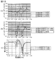
- FIG. 9B is a graph showing filter characteristics in application example 1 of the second embodiment.
- FIG. 10A is a circuit configuration diagram of a filter in application example 2 of the second embodiment.
- FIG. 10B is a graph showing filter characteristics in application example 2 of the second embodiment.
- FIG. 11A is a circuit configuration diagram of a filter in application example 3 of the second embodiment.
- FIG. 11B is a graph illustrating filter characteristics in application example 3 of the second exemplary embodiment.
- FIG. 12A is a circuit configuration diagram of a filter in application example 4 of the second embodiment.
- FIG. 12B is a graph illustrating filter characteristics in application example 4 of the second embodiment.
- FIG. 13A is a circuit configuration diagram of a filter in application example 5 of the second embodiment.
- FIG. 13B is a graph illustrating filter characteristics in Application Example 5 of Embodiment 2.
- FIG. 14 is a configuration diagram of the high-frequency front-end circuit and its peripheral circuits according to the third embodiment.
- FIG. 15 is a configuration diagram of a high-frequency front end circuit according to a modification of the third embodiment.
- FIG. 16 is a plan view schematically showing an electrode structure of a filter according to another embodiment.
- FIG. 1A is a circuit configuration diagram of a filter 10 according to the first embodiment.
- the filter 10 is a high-frequency filter circuit that is disposed, for example, in a front end portion of a multi-mode / multi-band mobile phone.
- the filter 10 is a band-pass filter that is built in a multi-band compatible mobile phone that complies with a communication standard such as LTE (Long Term Evolution) and filters high-frequency signals in a predetermined band.
- the filter 10 is an elastic wave filter device that filters high-frequency signals using an elastic wave resonator.
- the filter 10 includes a series arm resonator s1 and parallel arm resonators p1 and p2.
- the series arm resonator s1 is connected between the input / output terminal 11m (first input / output terminal) and the input / output terminal 11n (second input / output terminal). That is, the series arm resonator s1 is a series arm resonance circuit provided on a path connecting the input / output terminal 11m and the input / output terminal 11n.
- the series arm resonance circuit is not limited to the series arm resonator s1, but may be provided with a series arm resonance circuit including one or more elastic wave resonators. In the present embodiment, the series arm resonance circuit is configured by one elastic wave resonator, but may be configured by a plurality of elastic wave resonators.
- the series arm resonance circuit including a plurality of elastic wave resonators includes, for example, a longitudinally coupled resonator including a plurality of elastic wave resonators, or a plurality of divided resonances in which one elastic wave resonator is divided in series. Includes children. For example, by using a longitudinally coupled resonator as the series arm resonance circuit, it becomes possible to adapt to required filter characteristics such as enhancement of attenuation.
- the parallel arm resonator p1 is a first parallel arm resonator connected to a node (node x1 in FIG. 1A) and a ground (reference terminal) on a path connecting the input / output terminal 11m and the input / output terminal 11n. . That is, the parallel arm resonator p1 is a resonator provided in a parallel arm resonance circuit that connects the node x1 on the path and the ground.
- the parallel arm resonator p2 is a second parallel arm resonator connected to a node (node x1 in FIG. 1A) and a ground (reference terminal) on the path connecting the input / output terminal 11m and the input / output terminal 11n. . That is, the parallel arm resonator p2 is a resonator provided in the parallel arm resonance circuit that connects the node x1 on the series arm and the ground.
- parallel arm resonators p1 and p2 are connected between the same node x1 on the path and the ground.
- the parallel arm resonators p1 and p2 are connected in parallel and connected between the node x1 and the ground.
- the “same node” includes not only one point on the transmission line but also two different points on the transmission line located without a resonator or an impedance element.
- the node x1 is on the input / output terminal 11n side of the series arm resonator s1, but may be on the input / output terminal 11m side of the series arm resonator s1.
- the parallel arm resonators p1 and p2 form a parallel arm resonance circuit connected between the node x1 on the path connecting the input / output terminal 11m and the input / output terminal 11n (on the serial arm) and the ground. . That is, the parallel arm resonance circuit is provided in one parallel arm that connects the series arm and the ground. Therefore, the series arm resonance circuit (series arm resonator s1 in the present embodiment) has a ladder-type filter structure (in this embodiment, the parallel arm resonance circuit (parallel arm resonators p1 and p2 in the present embodiment)). 1-stage ladder type filter structure).
- the parallel arm resonance circuit constituted by the parallel arm resonators p1 and p2 forms the pass band of the filter 10 together with the series arm resonator s1.
- FIG. 1B is a plan view schematically showing the electrode structure of the filter 10 according to the first embodiment.
- each resonator (series arm resonator s1, parallel arm resonator p1 and p2) constituting the filter 10 is an elastic wave resonator using an elastic wave.
- the filter 10 can be constituted by an IDT (InterDigital Transducer) electrode formed on a piezoelectric substrate, so that a small and low-profile filter circuit having a high steep passage characteristic can be realized.
- the substrate having piezoelectricity is a substrate having piezoelectricity at least on the surface.
- the substrate may include, for example, a piezoelectric thin film on the surface, a film having a different sound velocity from the piezoelectric thin film, and a laminated body such as a support substrate.
- the substrate includes, for example, a laminate including a high sound speed support substrate and a piezoelectric thin film formed on the high sound speed support substrate, a high sound speed support substrate, and a low sound speed film formed on the high sound speed support substrate.
- a laminate including a piezoelectric thin film formed on the film may be used. Note that the substrate may have piezoelectricity throughout the substrate.
- Each resonator has an IDT electrode that excites an elastic wave, and a pair of reflectors arranged so as to sandwich the IDT electrode from both sides in the elastic wave propagation direction.
- the series arm resonator s1 includes an IDT electrode 111 and a pair of reflectors 112.
- the parallel arm resonator p ⁇ b> 1 includes an IDT electrode 121 and a pair of reflectors 122.
- the parallel arm resonator p ⁇ b> 2 includes an IDT electrode 131 and a pair of reflectors 132.
- the resonance frequency of the parallel arm resonator p2 (second parallel arm resonator) is higher than the resonance frequency of the parallel arm resonator p1 (first parallel arm resonator).
- the resonance frequency in the resonator is a frequency at a singular point where the impedance is minimized (ideally, a point where the impedance is 0).
- the antiresonance frequency of the parallel arm resonator p2 is higher than the antiresonance frequency of the parallel arm resonator p1.
- the antiresonance frequency in the resonator is a frequency at a singular point where the impedance becomes maximum (ideally, a point where the impedance becomes infinite).
- the IDT electrode 131 in the parallel arm resonator p2 has a duty ratio that is a ratio of the width of the plurality of electrode fingers to the pitch of the plurality of electrode fingers than the IDT electrode 121 in the parallel arm resonator p1.
- the IDT electrode 111 (a plurality of IDT electrodes when the series arm resonance circuit is a longitudinally coupled resonator) in the series arm resonator s1 (series arm resonance circuit) is connected to the IDT in the parallel arm resonator p1.
- the duty ratio is larger than that of the electrode 121.
- the width (line width) of the plurality of electrode fingers of the IDT electrode 111 of the series arm resonator s1 is W s1
- the space width between adjacent electrode fingers is S s1
- the width of the plurality of electrode fingers of the IDT electrode 121 of the parallel arm resonator p1 is W p1
- the space width between the adjacent electrode fingers is S p1
- the width of the electrode finger of the IDT electrode 131 of the parallel arm resonator p2 is W p2
- the space width between the adjacent electrode fingers is Sp2 .
- W p2 / (W p2 + S p2 ) that is the duty ratio of the IDT electrode 131 is larger than W p1 / (W p1 + S p1 ) that is the duty ratio of the IDT electrode 121, and is the duty ratio of the IDT electrode 111.
- a certain W s1 / (W s1 + S s1 ) is larger than W p1 / (W p1 + S p1 ) which is the duty ratio of the IDT electrode 121.
- the number of IDT electrodes 111, 121, and 131 and the crossing width are the same, but the number of at least one IDT electrode and the crossing width are the number of other IDT electrodes, and The crossing width may be different.
- each resonator constituting the filter 10 will be described in more detail by paying attention to an arbitrary resonator. Since the other resonators have substantially the same structure as the arbitrary resonator, detailed description thereof is omitted.
- FIG. 2 is an example of a diagram schematically showing the structure of the resonator in the present embodiment, where (a) is a plan view and (b) is a cross-sectional view of (a).
- the resonator shown in FIG. 2 is for explaining a typical structure of each resonator constituting the filter 10. For this reason, the number and length of electrode fingers constituting the IDT electrode of each resonator of the filter 10 are not limited to the number and length of electrode fingers of the IDT electrode shown in FIG.
- illustration is abbreviate
- the resonator includes an IDT electrode 101, a piezoelectric substrate 102 on which the IDT electrode 101 is formed, and a protective layer 103 that covers the IDT electrode 101.
- IDT electrode 101 As shown in FIGS. 2A and 2B, the resonator includes an IDT electrode 101, a piezoelectric substrate 102 on which the IDT electrode 101 is formed, and a protective layer 103 that covers the IDT electrode 101.
- protective layer 103 that covers the IDT electrode 101.
- the comb-tooth electrode 101a includes a plurality of electrode fingers 110a that are parallel to each other and a bus bar electrode 111a that connects the plurality of electrode fingers 110a.
- the comb-tooth electrode 101b includes a plurality of electrode fingers 110b that are parallel to each other and a bus bar electrode 111b that connects the plurality of electrode fingers 110b.
- the plurality of electrode fingers 110a and 110b are formed along a direction orthogonal to the propagation direction.
- each of the comb electrodes 101a and 101b may be referred to as an IDT electrode alone. However, in the following description, for the sake of convenience, it is assumed that one IDT electrode 101 is constituted by a pair of comb-tooth electrodes 101a and 101b.
- the IDT electrode 101 composed of the plurality of electrode fingers 110a and 110b and the bus bar electrodes 111a and 111b has a laminated structure of an adhesion layer 101g and a main electrode layer 101h as shown in FIG. It has become.
- the adhesion layer 101g is a layer for improving adhesion between the piezoelectric substrate 102 and the main electrode layer 101h, and Ti is used as a material, for example.
- the film thickness of the adhesion layer 101g is, for example, 12 nm.
- the main electrode layer 101h is made of, for example, Al containing 1% Cu.
- the film thickness of the main electrode layer 101h is, for example, 162 nm.
- the piezoelectric substrate 102 is a substrate on which the IDT electrode 101 is formed, and is made of, for example, LiTaO 3 piezoelectric single crystal, LiNbO 3 piezoelectric single crystal, KNbO 3 piezoelectric single crystal, crystal, or piezoelectric ceramic.
- the protective layer 103 is formed to cover the comb electrodes 101a and 101b.
- the protective layer 103 is a layer for the purpose of protecting the main electrode layer 101h from the external environment, adjusting frequency temperature characteristics, and improving moisture resistance, for example, a film mainly composed of silicon dioxide. .
- each resonator which the filter 10 has is not limited to the structure described in FIG.
- the IDT electrode 101 may not be a stacked structure of metal films but may be a single layer of metal films.
- the materials constituting the adhesion layer 101g, the main electrode layer 101h, and the protective layer 103 are not limited to the materials described above.
- the IDT electrode 101 may be made of, for example, a metal or an alloy such as Ti, Al, Cu, Pt, Au, Ag, or Pd, and is made of a plurality of laminated bodies made of the above metals or alloys. May be.
- the protective layer 103 may not be formed.
- the wavelength of the excited elastic wave is defined by the design parameters of the IDT electrode 101 and the like. That is, the resonance frequency and antiresonance frequency of the resonator are defined by the design parameters of the IDT electrode 101 and the like.
- design parameters of the IDT electrode 101 that is, design parameters of the comb electrode 101a and the comb electrode 101b will be described.
- the wavelength of the elastic wave is defined by the repetition period ⁇ of the plurality of electrode fingers 110a or 110b constituting the comb electrodes 101a and 101b shown in FIG.
- the electrode pitch (electrode period) is 1 ⁇ 2 of the repetition period ⁇
- the line width of the electrode fingers 110a and 110b constituting the comb electrodes 101a and 101b is W
- the adjacent electrode fingers 110a and electrodes When the space width between the finger 110b is S, it is defined by (W + S).
- the crossing width L of the IDT electrode 101 is obtained by viewing the electrode finger 110a of the comb electrode 101a and the electrode finger 110b of the comb electrode 101b from the propagation direction of the elastic wave.
- the electrode duty is the line width occupation ratio of the plurality of electrode fingers 110a and 110b, and is the ratio of the line width to the sum of the line width and the space width of the plurality of electrode fingers 110a and 110b. , W / (W + S).
- the film thickness of the IDT electrode 101 is the thickness h of the plurality of electrode fingers 110a and 110b.
- resonance frequency a singular point where the impedance is minimal (ideally a point where the impedance is 0) is referred to as a “resonance frequency”. Called. A singular point where the impedance is maximum (ideally a point where the impedance is infinite) is referred to as an “anti-resonance frequency”.
- FIG. 3 is a graph showing the characteristics of the filter 10 according to the first embodiment. Specifically, (a) of the figure is a graph showing impedance characteristics of the parallel arm resonators p1 and p2 and the series arm resonator s1.
- FIG. 4B is a graph showing the combined impedance characteristics (synthetic characteristics) of the parallel arm resonators p1 and p2 and the impedance characteristics of the series arm resonator s1.
- FIG. 4C is a graph showing the filter characteristics of the filter 10.
- the parallel arm resonator p1, the parallel arm resonator p2, and the series arm resonator s1 have the following impedance characteristics. Specifically, for the parallel arm resonator p1, the parallel arm resonator p2, and the series arm resonator s1, in this order, assuming that the resonance frequencies are frp1, frp2, frs1, and the antiresonance frequencies are fap1, fap2, and fas1, In this form, frp1 ⁇ frs1 ⁇ frp2 and fap1 ⁇ fas1 ⁇ fap2 are satisfied.
- the combined characteristics of the two parallel arm resonators (“parallel arm resonators p1 and p2) (“the combined characteristics of the parallel arms (p1 + p2)” in the figure) are the parallel arm resonators. It becomes minimum at the resonance frequency frp2 of p2 and the resonance frequency frp1 of the parallel arm resonator p1. Further, the combined characteristic becomes maximum at a frequency between the two resonance frequencies frp2 and frp1 and a frequency between the two antiresonance frequencies fap2 and fap1.
- the low-frequency side anti-resonance frequency of the two anti-resonance frequencies of the parallel arm resonance circuit and the resonance frequency frs1 of the series arm resonator s1 are placed close to each other. Configure the bandwidth.
- an attenuation band having the resonance frequency frp1 of the parallel arm resonator p1 as an attenuation pole is formed on the low pass band side, and in parallel on the high pass band side.
- An attenuation band is formed with the resonance frequency frp2 of the arm resonator p2 and the anti-resonance frequency fas1 of the series arm resonator s1 as attenuation poles.
- the low-frequency side anti-resonance frequency (Fa1 in FIG. 3) and the high-frequency side resonance frequency (Fr2 in FIG. 3) of the combined impedance characteristics of the parallel arm resonator p1 and the parallel arm resonator p2 are:
- An attenuation slope on the high band side of the pass band of the filter 10 is defined.
- the sharpness of the attenuation slope on the high side of the pass band is the difference between the low side anti-resonance frequency (Fa1 in FIG. 3) and the high side resonance frequency (Fr2 in FIG. 3) in the above synthetic impedance characteristic. It is influenced by the sharpness of the slope between.
- the Q of the anti-resonance frequency of the parallel arm resonator p1 (Fap1 in FIG. 3) and the Q of the resonance frequency of the parallel arm resonator p2 (Frp2 in FIG. 3) Affects.
- the anti-resonance frequency Q of the parallel arm resonator p1 is higher, in the combined impedance characteristic of the parallel arm resonance circuit (in this embodiment, the parallel connection circuit of the parallel arm resonators p1 and p2), Q of the side anti-resonance frequency (Fa1 in FIG. 3) becomes high.
- the higher the resonance frequency Q of the parallel arm resonator p2 the higher the Q of the resonance frequency (Fr2 in FIG.
- the sharpness of the slope between the anti-resonance frequency on the low frequency side and the resonance frequency on the high frequency side is improved.
- the sharpness on the high side of the passband can be improved.
- the higher the resonance frequency Q of the parallel arm resonator p2 the higher the Q of the attenuation pole (PoleH in FIG. 3) on the higher passband side (that is, the deeper the attenuation pole), and the parallel arm resonator p1.
- the anti-resonance frequency Q is higher, the loss in the passband (PB in FIG. 3) is suppressed. For this reason, the sharpness at the high side of the pass band can be improved.
- the combined impedance characteristic of the parallel arm resonance circuit is a characteristic in which the capacitance component of the parallel arm resonator p2 is combined with the characteristic of the parallel arm resonator p1 in the vicinity of the anti-resonance frequency on the low frequency side. Therefore, in addition to increasing the antiresonance frequency Q of the parallel arm resonator p1, in addition to increasing the Q of the capacitance component of the parallel arm resonator p2, that is, by reducing the series resistance of the parallel arm resonator p2, Loss in the passband of the filter 10 can be suppressed.
- the IDT electrode 131 in the parallel arm resonator p2 has a higher duty ratio than the IDT electrode 121 in the parallel arm resonator p1.
- the filter 10 can reduce the loss in the pass band and improve the sharpness on the high side of the pass band.
- the reason why such an effect is achieved will be described including the background to the present invention.
- the following typical example 1 has a frequency band different from that of the present embodiment, but the tendency of the resonance frequency and anti-resonance frequency Q to change depending on the duty ratio of the IDT electrode is the frequency of the present embodiment. The same applies to the band. Further, in the following typical example 1, the width of the plurality of electrode fingers is swung while the wavelength (repetition period) ⁇ of the elastic wave excited in the resonator is constant (that is, the pitch of the plurality of electrode fingers is constant). The duty ratio is changed.
- the duty ratio can be changed by changing the width of the plurality of electrode fingers.
- the electrode finger resistance decreases as the width of the plurality of electrode fingers increases. That is, by increasing the width of the plurality of electrode fingers, it is possible to reduce the series resistance that is a factor that degrades the resonance frequency Q in the resonator. That is, the resonance frequency Q can be increased by increasing the width of the plurality of electrode fingers of the IDT electrode constituting the resonator.
- the smaller the width of the plurality of electrode fingers the greater the insulation resistance that is a factor that increases the anti-resonance frequency Q. That is, the antiresonance frequency Q can be increased by reducing the width of the plurality of electrode fingers of the IDT electrode constituting the resonator.
- Table 1 shows details of the design parameters of the resonator at this time.
- fr represents the resonance frequency
- fa represents the antiresonance frequency
- Qr represents the resonance frequency Q
- Qa represents the antiresonance frequency Q.
- the film thickness h is the same for all typical examples.
- FIG. 4 shows a graph of changes in resonance frequency and Q, and anti-resonance frequency and changes in Q when the duty ratio is varied as shown in Table 1.
- FIG. 4 is a graph showing changes in the resonance frequency and anti-resonance frequency and Q when the duty ratio is varied in the resonator according to the first typical example.
- 4A is a graph showing changes in the resonance frequency and the anti-resonance frequency
- FIG. 4B is a graph showing a change in Q of the resonance frequency and the anti-resonance frequency.
- the resonance frequency Q (Qr) increases as the duty ratio increases.
- the antiresonance frequency Q (Qa) increases as the duty ratio decreases.
- changing the duty ratio causes the resonance frequency and the anti-resonance frequency to fluctuate.
- the acoustic velocity of the elastic wave excited in the resonator is changed by changing the width of the plurality of electrode fingers.
- the pitch of the plurality of electrode fingers is made constant, but the resonance frequency and the anti-resonance frequency can be changed by changing the pitch of the plurality of electrode fingers.
- the resonance frequency and the antiresonance frequency are lower as the pitch of the plurality of electrode fingers is larger. Therefore, by adjusting both the width and pitch of the plurality of electrode fingers, the frequency for exciting the elastic wave can be set to a desired frequency while setting the duty ratio to a desired duty ratio.
- the duty ratio of the IDT electrode 131 constituting the parallel arm resonator p2 is increased, and the duty ratio of the IDT electrode 121 constituting the parallel arm resonator p1 is decreased. By doing so, it is possible to reduce the loss in the passband and improve the sharpness on the high passband side. With respect to this, the impedance characteristics when the duty ratio is changed with particular attention to the parallel arm resonator p2 will be described with reference to FIG.
- FIG. 5 is a graph showing impedance characteristics when the duty ratio is changed in the resonator of the first embodiment.
- A of the figure represents the impedance characteristics of the parallel arm resonators p1 and p2 when the duty ratio is both 0.4, and the parallel arm resonator p1 when the duty ratio is 0.6
- B ) Is a graph showing an enlarged impedance characteristic near the resonance frequency of the parallel arm resonator p1 in (a).
- C) of the figure shows the combined impedance characteristics (synthetic characteristics) of the parallel arm resonators p1 and p2 when the duty ratio is both 0.4, and when the duty ratio of the parallel arm resonator p2 is 0.6.
- D is a graph showing an enlarged impedance characteristic in the vicinity of the resonance frequency on the high frequency side of (c).
- the resonance frequency Q may be higher than when the duty ratio is 0.4. Recognize. Further, as the resonance frequency Q of the parallel arm resonator p2 is increased, the combined impedance characteristics (synthetic characteristics) of the parallel arm resonators p1 and p2 are improved as shown in (c) and (d) of FIG. It can be seen that the Q of the resonance frequency on the band side (resonance frequency corresponding to the parallel arm resonator p2) increases.
- the filter of the example has the configuration of the filter 10 according to the above-described embodiment.
- the filter of the comparative example has substantially the same configuration as the filter of the embodiment, but is different in that the parallel arm resonator p1 and the parallel arm resonator p2 are configured by IDT electrodes having the same duty ratio.
- Table 2 shows the design parameters (duty ratio) of the filters of the example and the comparative example.
- the serial arm resonator s1 and the parallel arm resonators p1 and p2 of the comparative example are configured by IDT electrodes having the same duty ratio.
- the parallel arm resonator p1 of the embodiment is configured by an IDT electrode having a smaller duty ratio than the parallel arm resonator p1 of the comparative example.
- the parallel arm resonator p2 of the embodiment is configured by an IDT electrode having a larger duty ratio than the parallel arm resonator p2 of the comparative example. That is, in the embodiment, the parallel arm resonator p2 is configured by an IDT electrode having a duty ratio larger than that of the parallel arm resonator p1.
- the series arm resonator s1 of the embodiment is configured by IDT electrodes having the same duty ratio as compared with the series arm resonator s1 of the comparative example.
- the series arm resonator s1 is configured by an IDT electrode having a duty ratio larger than that of the parallel arm resonator p1.
- FIG. 6 is a graph showing the filter characteristics of the filters of the example and the comparative example.
- the loss in the passband is suppressed in the example compared to the comparative example. That is, in the embodiment, the loss in the passband is reduced as compared with the comparative example.
- the resonance frequency of the parallel arm resonator p2 is the parallel arm resonator p1 (first The anti-resonance frequency of the parallel arm resonator p1 is higher than the anti-resonance frequency of the parallel arm resonator p1.
- the IDT electrode 131 in the parallel arm resonator p2 has a duty ratio larger than that of the IDT electrode 121 in the parallel arm resonator p1.
- the resonance frequency Q increases as the duty ratio of the IDT electrode increases, and conversely, the anti-resonance frequency Q increases as the duty ratio of the IDT electrode decreases.
- the filter characteristics the higher the resonance frequency Q of the parallel arm resonator p2 and the higher the antiresonance frequency Q of the parallel arm resonator p1, the lower the loss in the passband and the higher the clearness of the passband. Can be improved.
- the duty ratio of the IDT electrode 131 constituting the parallel arm resonator p2 larger than the duty ratio of the IDT electrode 121 constituting the parallel arm resonator p1
- the loss in the pass band is reduced and the pass band is increased. Can improve the sharpness of the side.
- the IDT electrode 111 in the series arm resonator s1 (series arm resonance circuit) has a duty ratio larger than that of the IDT electrode 121 in the parallel arm resonator p1.
- the passband of the filter 10 includes the resonance frequency of the series arm resonator s1 and the anti-resonance frequency on the low band side of the parallel arm resonance circuit (in this embodiment, the parallel connection circuit of the parallel arm resonators p1 and p2). Formed with.
- the resonance frequency Q increases as the duty ratio of the IDT electrode increases, and conversely, the anti-resonance frequency Q increases as the duty ratio of the IDT electrode decreases. For this reason, it is possible to further reduce the loss in the passband by increasing the duty ratio of the IDT electrode 111 constituting the series arm resonator s1.
- the parallel arm resonators p1 and p2 are connected in parallel to each other and connected to the same node x1 (node) of the series arm.
- the parallel arm resonators p1 and p2 may be connected in series with each other and connected to the same node x1 (node) of the series arm. Therefore, such a filter will be described as a filter according to a modification of the first embodiment.
- FIG. 7A is a circuit configuration diagram of a filter 10A according to a modification of the first embodiment.
- FIG. 7B is a plan view schematically illustrating an electrode structure of a filter 10A according to a modification of the first embodiment.
- the filter 10A shown in these drawings includes an input / output terminal 11m (first input / output terminal) and parallel arm resonators p1 and p2 connected in series. The difference is that it is connected between the same node x1 in the path connecting the input / output terminal 11n (second input / output terminal) and the ground.
- the parallel arm resonator p1 has one terminal connected to the node x1 and the other terminal connected to one terminal of the parallel arm resonator p2.
- the parallel arm resonator p2 has one terminal connected to the other terminal of the parallel arm resonator p1, and the other terminal connected to the ground.
- the connection order of the parallel arm resonators p1 and p2 is not limited to this, and the connection order may be reversed.
- FIG. 8 is a graph showing characteristics of the filter 10A according to the modification of the first embodiment.
- the Q of the antiresonance frequency (Fap1 in FIG. 8) of the parallel arm resonator p1 and the parallel arm are the same as the characteristics of the filter 10 according to the first embodiment.
- the Q of the resonance frequency of the resonator p2 affects the sharpness on the high side of the passband. The specific mechanism related to this is the same as that in the first embodiment, and a detailed description thereof will be omitted.
- the combined impedance characteristics of the parallel arm circuit are combined with the characteristics of the parallel arm resonator p1 and the capacitance component of the parallel arm resonator p2 in the vicinity of the anti-resonance frequency on the low frequency side. Characteristics. Therefore, in addition to increasing the antiresonance frequency Q of the parallel arm resonator p1, in addition to increasing the Q of the capacitance component of the parallel arm resonator p2, that is, by reducing the series resistance of the parallel arm resonator p2, Loss in the passband of the filter 10A can be suppressed.
- the parallel arm resonator p2 is configured by the IDT electrode having a duty ratio larger than that of the parallel arm resonator p1, so that, similarly to the first embodiment, It is possible to reduce the loss on the high side of the passband and improve the sharpness.
- Embodiment 2 The configuration of the filter (elastic wave filter device) according to the first embodiment and its modification can be applied to a tunable filter having a variable pass band. Therefore, as a filter according to Embodiment 2, such a tunable filter will be described using application examples 1 to 5.
- application examples 1 to 4 are application examples of the filter 10 according to the first embodiment to the tunable filter
- application example 5 is an example of the filter 10A according to the modification of the first embodiment. This is an application example to a tunable filter.
- Each of the tunable filters of Application Examples 1 to 5 described below includes a switch element connected in series or in parallel to the parallel arm resonator p1 or the parallel arm resonator p2, and the switch element is turned on (ON).
- the pass band is switched according to non-conduction (off).
- the switch element is turned on and off in accordance with a control signal from a control unit such as an RF signal processing circuit (RFIC: Radio Frequency Integrated Circuit).
- RFIC Radio Frequency Integrated Circuit
- FIG. 9A is a circuit configuration diagram of a filter 20A according to application example 1 of the second embodiment.
- the filter 20A shown in the same figure further includes at least one of the parallel arm resonators p1 and p2 (first parallel arm resonator and second parallel arm resonator) (this application example). Then, it has a pair of capacitor C and switch SW connected in series to the parallel arm resonator p2) and connected in parallel to each other. Accordingly, the filter 20A can switch between the first pass characteristic and the second pass characteristic according to the conduction and non-conduction of the switch SW. Specifically, in this application example, the pair of capacitors C and switches SW connected in parallel to each other are connected in series only to the parallel arm resonator p2 of the parallel arm resonators p1 and p2.
- a circuit in which the capacitor C and the switch SW are connected in parallel is connected in series to the parallel arm resonator p2 between the node x1 and the ground, and specifically, the ground and the parallel arm resonator p2 are connected. Are connected in series.
- the capacitor C and the switch SW may be connected between the node x1 and the parallel arm resonator p2.
- the capacitor C is an impedance element connected in series to the parallel arm resonator p2.
- the frequency variable width of the passband of the filter 20A depends on the constant of the capacitor C. For example, the smaller the constant of the capacitor C, the wider the frequency variable width. For this reason, the constant of the capacitor C can be appropriately determined according to the frequency specification required for the filter 20A.
- the capacitor C may be a variable capacitor such as a variable gap and a DTC (Digital Tunable Capacitor). As a result, the frequency variable width can be finely adjusted.
- the switch SW is, for example, a SPST (Single Pole Single Throw) type switch element in which one terminal is connected to a connection node between the parallel arm resonator p2 and the capacitor C and the other terminal is connected to the ground.
- the switch SW switches between conduction (on) and non-conduction (off) in accordance with a control signal from a control unit (not shown), thereby bringing the connection node and ground into conduction or non-conduction.
- the switch SW may be a FET (Field Effect Transistor) switch made of GaAs or CMOS (Complementary Metal Oxide Semiconductor), or a diode switch.
- FET Field Effect Transistor
- CMOS Complementary Metal Oxide Semiconductor
- the switch SW can be constituted by one FET switch or a diode switch, the filter 20A can be reduced in size.
- the parallel arm resonators p1 and p2, the capacitor C, and the switch SW are parallel arms connected between the node x1 on the path connecting the input / output terminal 11m and the input / output terminal 11n (on the serial arm) and the ground.
- a resonant circuit is configured. That is, the parallel arm resonance circuit is provided in one parallel arm that connects the series arm and the ground. Therefore, the filter 20A has a one-stage ladder-type filter structure including the series arm resonator s1 and the parallel arm resonance circuit.
- the frequency at which the impedance is minimized and the frequency at which the impedance is maximized are both on the low frequency side or on the high frequency side depending on whether the switch SW is on (conductive) or off (nonconductive). shift. This will be described later together with the characteristics of the filter 20A.
- FIG. 9B is a graph showing characteristics of the filter 20A in the application example 1 of the second embodiment.
- (a) of the figure is a graph showing impedance characteristics of a single resonator (parallel arm resonators p1 and p2 and series arm resonator s1 respectively).
- (B) of the same figure is a synthetic impedance characteristic (synthetic characteristic) of the parallel arm resonance circuit (a circuit constituted by the parallel arm resonators p1 and p2 and the capacitor C and the switch SW in this application example) when the switch SW is on / off. ) In comparison.
- impedance characteristics of the series arm resonator s1 are also shown.
- (C) of the figure is a graph showing comparison of filter characteristics when the switch SW is on / off.
- the filter 20A has a pass band defined by the low-frequency side anti-resonance frequency of the two anti-resonance frequencies of the parallel arm resonance circuit and the resonance frequency frs1 of the series arm resonator s1.
- the passband low band side pole (attenuation pole) is defined by the resonance frequency frp1 of the arm resonator p1, and the passband high band side by the resonance frequency frp2 of the parallel arm resonator p2 and the antiresonance frequency fas1 of the series arm resonator s1.
- the first pass characteristic is defined, in which a pole (attenuation pole) is defined.
- the switch SW when the switch SW is off, the impedance characteristic of the parallel arm resonance circuit is affected by the capacitor C. That is, in this state, the combined characteristic of the two parallel arm resonators (parallel arm resonators p1 and p2) and the capacitor C becomes the impedance characteristic of the parallel arm resonance circuit.
- the capacitor C is added only to the parallel arm resonator p2 when the switch SW is off. For this reason, as shown by the black arrow in (b) of the figure, when the switch SW is switched from on to off, the two resonance frequencies in the impedance characteristics of the parallel arm resonance circuit (the combined characteristics of the parallel arms in the figure) Among them, the resonance frequency on the high frequency side and the anti-resonance frequency on the low frequency side of the two anti-resonance frequencies are both shifted to the high frequency side.
- the anti-resonance frequency on the low band side and the resonance frequency on the high band side of the parallel arm resonance circuit define an attenuation slope on the high band side of the passband of the filter 20A. Therefore, as shown in (c) of the figure, when the switch SW is switched from on to off, the pass characteristic of the filter 20A maintains the steepness of the attenuation slope on the high side of the pass band from the first pass characteristic. While switching to the second pass characteristic shifted to the high frequency side. In other words, the filter 20A can switch the frequency of the attenuation pole on the high side of the passband according to the switching of the switch SW on and off, and can suppress an increase in insertion loss at the high end of the passband. .
- the filter 20A constitutes a tunable filter that can reduce loss and improve sharpness on the high side of the passband.
- the impedance element is not limited to a capacitor, and may be an inductor, for example.
- an inductor is used as the impedance element, the shift direction of the attenuation slope when the switch SW is turned on / off is different from that in the above configuration. Specifically, in the second pass characteristic when the switch SW is off, the attenuation slope is shifted to the low frequency side as compared with the first pass characteristic when the switch SW is on.
- the frequency variable width of the passband of the filter 20A depends on the constant of the inductor. For example, the larger the inductor constant, the wider the frequency variable width. For this reason, the constant of the inductor can be appropriately determined according to the frequency specification required for the filter 20A.
- the inductor may be a variable inductor using MEMS (Micro Electro Mechanical Systems). As a result, the frequency variable width can be finely adjusted.
- FIG. 10A is a circuit configuration diagram of a filter 20B in application example 2 of the second embodiment.
- the filter 20B shown in FIG. 9 includes a pair of capacitors C and a switch SW connected in parallel with each other, and is connected in series only to the parallel arm resonator p1 of the parallel arm resonators p1 and p2. The connection is different.
- FIG. 10B is a graph showing characteristics of the filter 20B in the application example 2 of the second embodiment. Specifically, (a) and (b) in the same figure are graphs showing the impedance characteristics of a single resonator and the combined impedance characteristics of the parallel arm resonance circuit, as in (a) and (b) of FIG. 9B. is there. (C) of the figure is a graph showing comparison of filter characteristics when the switch SW is on / off.
- the capacitor C is added only to the parallel arm resonator p1 when the switch SW is off. For this reason, as shown by the black arrow in (b) of the figure, when the switch SW is switched from on to off, the two resonance frequencies in the impedance characteristics of the parallel arm resonance circuit (the combined characteristics of the parallel arms in the figure) The low-frequency side resonance frequency and the low-frequency side anti-resonance frequency of the two anti-resonance frequencies are both shifted to the high-frequency side.
- the anti-resonance frequency on the low frequency side and the resonance frequency on the low frequency side of the parallel arm resonance circuit define an attenuation slope on the low frequency side of the pass band of the filter 20B. Therefore, as shown in FIG. 5C, when the switch SW is switched from on to off, the pass characteristic of the filter 20B maintains the steepness of the attenuation slope on the low pass band side from the first pass characteristic. While switching to the second pass characteristic shifted to the high frequency side. In other words, the filter 20B can switch the frequency of the attenuation pole on the low passband side according to the switching of the switch SW on and off, and can suppress an increase in insertion loss at the low end of the passband. .
- the filter 20B constitutes a tunable filter that can reduce loss and improve sharpness on the high side of the passband.
- FIG. 11A is a circuit configuration diagram of a filter 20C in application example 3 of the second embodiment.
- the filter 20C shown in the figure shifts both the attenuation slopes on the high side of the passband and the low side of the passband.
- the filter 20C includes a pair of capacitors C (impedance elements) included in the filter 20B illustrated in FIG. 10A, and a capacitor C1 and a switch SW1 corresponding to the switch SW.
- the filter 20C includes a pair (other pair) of capacitors C (impedance elements) included in the filter 20A illustrated in FIG. 9A and a capacitor C2 and a switch SW2 corresponding to the switch SW.
- FIG. 11B is a graph showing characteristics of the filter 20C in the application example 3 of the second embodiment. Specifically, (a) and (b) in the same figure are similar to (a) and (b) in FIG. 10B, and impedance characteristics of a single resonator and a parallel arm resonance circuit (in this application example, parallel arm resonance). It is a graph showing the synthetic
- the pass characteristic of the filter 20C is changed from the first pass characteristic to the pass band high band side and the pass band low band side. Is switched to the second passing characteristic shifted to the high frequency side while maintaining the steepness.
- the filter 20C can switch the frequencies of the attenuation poles on the high side of the passband and the low side of the passband according to the switching of the conduction and non-conduction of the switches SW1 and WS2, and at the high end of the passband.
- an increase in insertion loss at the low end of the passband can be suppressed. For this reason, for example, the filter 20C can shift the center frequency while maintaining the bandwidth.
- the filter 20 ⁇ / b> C constitutes a tunable filter that can reduce loss and improve sharpness on the high side of the passband.
- the filter 20C does not need to turn on / off both the switches SW1 and SW2, and may turn them on / off individually. However, when both the switches SW1 and SW2 are turned on / off, the number of control lines for controlling the switches SW1 and SW2 can be reduced, so that the configuration of the filter 20C can be simplified.
- the high band end of the pass band can be varied according to the on / off state of the switch SW2 connected in series to the parallel arm resonator p2.
- the low band end of the pass band can be varied according to the on / off state of the switch SW1 connected in series to the parallel arm resonator p1.
- both the switches SW1 and SW2 on or off, it is possible to shift both the low band end and high band end of the pass band to the low band side or the high band side. That is, the center frequency of the pass band can be shifted to the low frequency side or the high frequency side.
- both the low band end and high band end of the pass band are shifted so that these frequency differences are widened or narrowed. be able to. That is, the pass band width can be varied while making the center frequency of the pass band substantially constant.
- the other of the low band end and the high band of the pass band is fixed while the other one of the low band end and the high band end is fixed. Can be shifted to the side. That is, the low band end or high band end of the pass band can be varied.
- FIG. 12A is a circuit configuration diagram of a filter 20D in application example 4 of the second embodiment.
- the filter 20D shown in the same figure has a pair of capacitors C and a switch SW connected in parallel to each other, and the parallel arm resonator p1 and the parallel arm resonator p2 are connected in parallel. The difference is that they are connected in series to the circuit.
- FIG. 12B is a graph showing characteristics of the filter 20D in the application example 4 of the second embodiment. Specifically, (a) and (b) in the figure are graphs showing the impedance characteristics of a single resonator and the combined impedance characteristics of the parallel arm resonance circuit, as in (a) and (b) of FIG. 10B. is there. (C) of the figure is a graph showing comparison of filter characteristics when the switch SW is on / off.
- the capacitor C is added to the parallel arm resonators p1 and p2 connected in parallel when the switch SW is off. For this reason, as shown by the black arrow in (b) of the figure, when the switch SW is switched from on to off, two anti-resonances are obtained in the impedance characteristics of the parallel arm resonance circuit (the combined characteristics of the parallel arms in the figure). Neither frequency shifts, but both two resonance frequencies shift to the high frequency side.
- the pass characteristic of the filter 20D is such that the poles (attenuation poles) on both sides of the pass band from the first pass characteristic are higher. To the second passage characteristic shifted to.
- the filter 20D constitutes a tunable filter that can reduce loss and improve sharpness on the high side of the passband.
- FIG. 13A is a circuit configuration diagram of a filter 20E in application example 5 of the second embodiment.
- the filter 20E shown in the figure is further connected in parallel to one of the parallel arm resonators p1 and p2 (the first parallel arm resonator and the second parallel arm resonator) compared to the filter 10A shown in FIG. 7A. It has a switch SW.
- the switch SW is connected in parallel to the parallel arm resonator p2.
- the switch SW may be connected in parallel to the parallel arm resonator p1 when the influence of the diffraction loss of the parallel arm resonator p2 is allowed according to the required specifications for the filter 20E.
- FIG. 13B is a graph showing characteristics of the filter 20E in the application example 5 of the second embodiment. Specifically, (a) and (b) in the same figure are similar to (a) and (b) in FIG. 9B, the impedance characteristics of the resonator alone and the parallel arm resonance circuit (in this application example, parallel arm resonance). It is a graph showing the synthetic
- the impedance characteristic of the parallel arm resonance circuit (the combined characteristic of the parallel arms in the drawing) is the impedance characteristic of the parallel arm resonator p1 alone.
- the parallel arm resonator p2 is added to the parallel arm resonator p1.
- the impedance characteristic of the parallel arm resonance circuit (the combined characteristic of the parallel arms in the figure) is the parallel arm resonator.
- the IDT electrode in the parallel arm resonator p2 is configured by the IDT electrode having a duty ratio larger than that of the IDT electrode in the parallel arm resonator p1, it is parallel to the parallel arm resonator p1.
- the characteristics when the arm resonator p2 is added can reduce the loss on the high side of the passband and improve the sharpness. That is, the filter 20E constitutes a tunable filter that can reduce loss and improve sharpness on the high side of the passband.
- FIG. 14 is a configuration diagram of the high-frequency front-end circuit 1 and its peripheral circuits according to the third embodiment.
- a high-frequency front-end circuit 1 an antenna element 2, and an RF signal processing circuit (RFIC) 3 are shown.
- the high frequency front end circuit 1 and the RFIC 3 constitute a communication device 4.
- the antenna element 2, the high-frequency front end circuit 1, and the RFIC 3 are disposed, for example, in a front end portion of a mobile phone that supports multimode / multiband.
- the antenna element 2 is a multiband antenna that transmits and receives a high-frequency signal and conforms to a communication standard such as LTE.
- the antenna element 2 may not correspond to, for example, all the bands of the communication device 4, and may correspond to only the bands of the low frequency band group or the high frequency band group.
- the antenna element 2 is not built in the communication device 4 and may be provided separately from the communication device 4.
- the high frequency front end circuit 1 is a circuit that transmits a high frequency signal between the antenna element 2 and the RFIC 3. Specifically, the high-frequency front end circuit 1 transmits a high-frequency signal (here, a high-frequency transmission signal) output from the RFIC 3 to the antenna element 2 via the transmission-side signal path. The high-frequency front end circuit 1 transmits a high-frequency signal (here, a high-frequency reception signal) received by the antenna element 2 to the RFIC 3 via the reception-side signal path.
- a high-frequency signal here, a high-frequency transmission signal
- the high-frequency front end circuit 1 transmits a high-frequency signal (here, a high-frequency reception signal) received by the antenna element 2 to the RFIC 3 via the reception-side signal path.
- the high-frequency front-end circuit 1 includes a duplexer 120, a transmission amplifier circuit 140, and a reception amplifier circuit 160.
- the duplexer 120 is a multiplexer that includes a transmission-side filter 120Tx and a reception-side filter 120Rx, and includes the above-described elastic wave filter device in at least one of them.
- the transmission-side filter 120Tx and the reception-side filter 120Rx have the antenna-side input / output terminals bundled together and connected to the antenna element 2, and the other terminals connected to the transmission amplifier circuit 140 or the reception amplifier circuit 160.
- the transmission amplifier circuit 140 is a power amplifier that amplifies the power of the high-frequency transmission signal output from the RFIC 3.
- the reception amplification circuit 160 is a low noise amplifier that amplifies the power of the high frequency reception signal received by the antenna element 2.
- RFIC 3 is an RF signal processing circuit that processes high-frequency signals transmitted and received by the antenna element 2. Specifically, the RFIC 3 processes a high-frequency signal (here, a high-frequency reception signal) input from the antenna element 2 via the reception-side signal path of the high-frequency front-end circuit 1 by down-conversion or the like, and performs the signal processing. The received signal generated in this way is output to a baseband signal processing circuit (not shown). Further, the RFIC 3 performs signal processing on the transmission signal input from the baseband signal processing circuit by up-conversion or the like, and transmits a high-frequency signal (here, a high-frequency transmission signal) generated by the signal processing to the high-frequency front-end circuit 1. Output to the side signal path.
- a high-frequency signal here, a high-frequency reception signal
- the RFIC 3 performs signal processing on the transmission signal input from the baseband signal processing circuit by up-conversion or the like, and transmits a high-frequency signal (here, a high-
- high-frequency front-end circuit 1 by providing the elastic wave filter device described above, low loss and high selectivity (inhibition of mutual interference with other bands adjacent to the own band) are achieved. Both can be achieved. For this reason, it is particularly useful as the high-frequency front-end circuit 1 applied to the communication device 4 that supports multiband.
- the filter (elastic wave filter device) described in the first and second embodiments and the modifications thereof is a high frequency front corresponding to a system having a larger number of bands used than the high frequency front end circuit 1 according to the third embodiment. It can also be applied to an end circuit. Therefore, in this modification, such a high-frequency front end circuit will be described.
- FIG. 15 is a configuration diagram of a high-frequency front-end circuit 1A according to a modification of the third embodiment.
- the high-frequency front end circuit 1A includes an antenna terminal ANT, transmission terminals Tx1 and Tx2, and reception terminals Rx1 and Rx2, and a switch group 110 including a plurality of switches in order from the antenna terminal ANT side.
- the filter group 120A includes a plurality of filters, transmission-side switches 130A and 130B, reception-side switches 150A, 150B, and 150C, transmission amplification circuits 140A and 140B, and reception amplification circuits 160A and 160B.
- the switch group 110 connects the antenna terminal ANT and a signal path corresponding to a predetermined band according to a control signal from a control unit (not shown), and includes, for example, a plurality of SPST type switches.
- the number of signal paths connected to the antenna terminal ANT is not limited to one, and a plurality of signal paths may be used. That is, the high-frequency front end circuit 1A may support carrier aggregation.
- the filter group 120A includes, for example, a plurality of filters (including a duplexer) having the following band in the pass band.
- the band includes (i) Band 12 transmission band, (ii) Band 13 transmission band, (iii) Band 14 transmission band, (iv) Band 27 (or Band 26) transmission band, (v) Band 29 and Band 14 (or Band 12, Band 67 and Band 13) reception band, (vi-Tx) Band 68 and Band 28a (or Band 68 and Band 28b) transmission band, (vi-Rx) Band 68 and Band 28a (or Band 68 and Band 28b) reception band, vii-Tx) Band20 transmission band, (vii-Rx) Band20 reception band, (viii) Band27 (or Band26) reception band, (ix-Tx) Band8 transmission band, and (ix-Rx) Band8 Reception bandwidth.
- the transmission-side switch 130A is a switch circuit having a plurality of selection terminals connected to a plurality of transmission signal paths on the low band side and a common terminal connected to the transmission amplifier circuit 140A.
- the transmission-side switch 130B is a switch circuit having a plurality of selection terminals connected to a plurality of transmission-side signal paths on the high band side and a common terminal connected to the transmission amplifier circuit 140B.
- These transmission-side switches 130A and 130B are switch circuits that are provided in the previous stage of the filter group 120A (here, the previous stage in the transmission-side signal path) and the connection state is switched according to a control signal from a control unit (not shown). .
- the high-frequency signal (here, the high-frequency transmission signal) amplified by the transmission amplifier circuits 140A and 140B is output from the antenna terminal ANT to the antenna element 2 (see FIG. 14) via the predetermined filter of the filter group 120A. .
- the reception side switch 150A is a switch circuit having a plurality of selection terminals connected to a plurality of reception side signal paths on the low band side and a common terminal connected to the reception amplification circuit 160A.
- the reception side switch 150B has a common terminal connected to a reception side signal path of a predetermined band (here, Band20), and two selection terminals connected to a common terminal of the reception side switch 150A and a common terminal of the reception side switch 150B. And a switch circuit.
- the reception-side switch 150C is a switch circuit having a plurality of selection terminals connected to a plurality of reception-side signal paths on the high band side and a common terminal connected to the reception amplification circuit 160B.
- reception-side switches 150A to 150C are provided in the subsequent stage of the filter group 120A (here, the subsequent stage in the reception-side signal path), and the connection state is switched according to a control signal from a control unit (not shown).
- the high-frequency signal here, the high-frequency reception signal
- the antenna terminal ANT is amplified by the reception amplifier circuits 160A and 160B via the predetermined filter of the filter group 120A, and the RFIC3 is received from the reception terminals Rx1 and Rx2. (See FIG. 14).
- the RFIC corresponding to the low band and the RFIC corresponding to the high band may be provided separately.
- the transmission amplifier circuit 140A is a power amplifier that amplifies a low-band high-frequency transmission signal
- the transmission amplifier circuit 140B is a power amplifier that amplifies a high-band high-frequency transmission signal.
- the reception amplification circuit 160A is a low noise amplifier that amplifies the power of the low-band high-frequency reception signal
- the reception amplification circuit 160B is a low-noise amplifier that amplifies the power of the high-band high-frequency reception signal.
- the high-frequency front-end circuit 1A configured as described above includes (iv) a filter 20A according to Application Example 1 of Embodiment 2 as a filter having a transmission band of Band 27 (or Band 26) in the pass band. That is, the filter switches the pass band between the Band 27 transmission band and the Band 26 transmission band in accordance with the control signal.
- the high-frequency front-end circuit 1A includes a filter 20B according to Application Example 2 of Embodiment 2 as a reception filter having a reception band of (vi-Rx) Band 68 and Band 28a (or Band 68 and Band 28b) in the pass band, (Vi-Tx)
- the filter 20C according to the application example 3 of the second embodiment is provided as a transmission filter having transmission bands of Band68 and Band28a (or Band68 and Band28b) in the passband. That is, the duplexer constituted by the transmission filter and the reception filter switches the pass band between the transmission band of Band68 and Band28a and the transmission band of Band68 and Band28b according to the control signal, and the reception band of Band68 and Band28a and Band68. And the reception band of Band 28b.
- the high-frequency front-end circuit 1A includes (viii) a filter 20B according to Application Example 2 of Embodiment 2 as a filter having a reception band of Band27 (or Band26) in the passband. That is, the filter switches the pass band between the Band 27 transmission band and the Band 26 transmission band in accordance with the control signal.
- a filter is provided for each band by including the filters 20A to 20C (elastic wave filter devices) according to the application examples 1 to 3 of the second embodiment. Since the number of filters can be reduced compared to the case, the size can be reduced.
- the transmission-side switches 130A and 130B and the reception-side switches 150A to 150C (stages) provided at the front stage or the rear stage of the filter group 120A (a plurality of acoustic wave filter devices) Switch circuit).
- the transmission amplifier circuits 140A and 140B or the reception amplifier circuits 160A and 160B amplifier circuits corresponding to a plurality of acoustic wave filter devices can be shared. Accordingly, the high-frequency front end circuit 1A can be reduced in size and cost.
- the transmission side switches 130A and 130B and the reception side switches 150A to 150C may be provided.
- the number of transmission side switches 130A and 130B and the number of reception side switches 150A to 150C are not limited to the above-described numbers, and, for example, one transmission side switch and one reception side switch are provided. It doesn't matter.
- the number of selection terminals and the like of the transmission side switch and the reception side switch is not limited to this embodiment, and may be two each.
- the configuration of the filter according to the first embodiment and its modification may be applied to at least one of the plurality of filters included in the filter group.
- the communication device 4 including the above-described high-frequency front-end circuit and RFIC 3 (RF signal processing circuit) is also included in the present invention. According to such a communication device 4, it is possible to achieve low loss and high selectivity.
- the aspect ratios of the IDT electrodes constituting the series arm resonator s1 and the parallel arm resonators p1 and p2 may be the same or different. However, from the viewpoint of improving the filter characteristics, the parallel arm resonator The aspect ratio of the IDT electrode 131 constituting p2 is preferably smaller than the aspect ratio of the IDT electrode 121 constituting the parallel arm resonator p1.
- FIG. 16 is a plan view schematically showing the electrode structure of the filter 10B configured as described above.
- the IDT electrode in the parallel arm resonator p32 (second parallel arm resonator) has a crossing of the plurality of electrode fingers with respect to the logarithm of the plurality of electrode fingers than the IDT electrode in the parallel arm resonator p31 (first parallel arm resonator).
- the aspect ratio which is the width ratio, is small.
- the aspect ratio L / N satisfies L p1 / N p1 > L p2 / N p2 .
- the logarithms of the IDT electrodes of the respective resonators are shown to be equal. However, in an actual design, these logarithms are rarely equal.
- design parameters such as the number of IDT electrodes and the crossing width of each resonator can be appropriately determined according to the specifications required for each resonator. That is, here, the IDT electrode in the parallel arm resonator p32 has a larger duty ratio and a smaller aspect ratio than the IDT electrode in the parallel arm resonator p31.
- the inventor of the present application utilizes the fact that the resonance frequency and anti-resonance frequency Q of the resonator change depending on not only the duty ratio of the IDT electrode constituting the resonator but also the aspect ratio of the IDT electrode constituting the resonator. It was found that the filter characteristics can be improved. That is, regarding the impedance characteristics of a single resonator, the resonance frequency Q increases as the duty ratio of the IDT electrode increases and the aspect ratio decreases, and conversely, the antiresonance frequency increases as the duty ratio of the IDT electrode decreases and the aspect ratio increases. Q increases.
- the series arm resonator s1 is not limited to an elastic wave resonator using a surface acoustic wave, and may be formed of an elastic wave resonator using a bulk wave or a boundary acoustic wave, for example. That is, the series arm resonator s1 may not be configured by the IDT electrode. Even in the elastic wave filter device having such a series arm resonator s1, the elastic wave resonator generally exhibits a high Q characteristic, so that low loss and high selectivity (other than adjacent to its own band) can be achieved. (Suppression of mutual interference with other bands) can be achieved.
- each resonator has a reflector.
- the resonator may not have a reflector.
- an inductor or a capacitor may be connected between each component.
- the inductor may include a wiring inductor formed by wiring that connects the components.
- the present invention can be widely used in communication devices such as mobile phones as small filters, multiplexers, front-end circuits and communication devices applicable to multiband systems.
Abstract
Description
[1.フィルタの回路構成]
図1Aは、実施の形態1に係るフィルタ10の回路構成図である。 (Embodiment 1)
[1. Filter circuit configuration]
FIG. 1A is a circuit configuration diagram of a
[2-1.電極構造]
次に、フィルタ10の構造について、説明する。 [2. Construction]
[2-1. Electrode structure]
Next, the structure of the
以下、フィルタ10を構成する各共振子の構造について、任意の共振子に着目してより詳細に説明する。なお、他の共振子については、当該任意の共振子と概ね同じ構造を有するため、詳細な説明を省略する。 [2-2. Resonator structure]
Hereinafter, the structure of each resonator constituting the
次に、本実施の形態に係るフィルタ10のフィルタ特性について、説明する。 [3. Filter characteristics]
Next, the filter characteristics of the
一般的に、弾性波フィルタ装置では、当該弾性波フィルタ装置を構成する共振子のQによってフィルタ特性が制約されてしまうため、フィルタ特性の改善を図ることが難しい。これに対し、本願発明者は、共振子を構成するIDT電極のデューティ比に依存して当該共振子の共振周波数及び反共振周波数のQが変わることを利用して、フィルタ特性を改善できることを見出した。このことに関し、以下、具体的な典型例に基づき説明する。 [4. Improvement mechanism of filter characteristics]
In general, in an acoustic wave filter device, the filter characteristics are restricted by the Q of a resonator constituting the acoustic wave filter device, so it is difficult to improve the filter characteristics. In contrast, the inventor of the present application has found that the filter characteristics can be improved by utilizing the fact that the resonance frequency and anti-resonance frequency Q of the resonator change depending on the duty ratio of the IDT electrode constituting the resonator. It was. This will be described below based on a specific typical example.

次に、本実施の形態に係るフィルタ10によって奏される効果について、実施例を用いて比較例と対比しながら説明する。 [5. Effect]
Next, the effect produced by the

上記実施の形態では、並列腕共振子p1及びp2は、互いに並列接続されて直列腕の同一ノードx1(ノード)に接続されているとした。しかし、並列腕共振子p1及びp2は、互いに直列接続されて直列腕の同一ノードx1(ノード)に接続されていてもかまわない。そこで、実施の形態1の変形例に係るフィルタとして、このようなフィルタについて説明する。 (Modification of Embodiment 1)
In the above embodiment, the parallel arm resonators p1 and p2 are connected in parallel to each other and connected to the same node x1 (node) of the series arm. However, the parallel arm resonators p1 and p2 may be connected in series with each other and connected to the same node x1 (node) of the series arm. Therefore, such a filter will be described as a filter according to a modification of the first embodiment.
上記実施の形態1及びその変形例に係るフィルタ(弾性波フィルタ装置)の構成は、通過帯域が可変なチューナブルフィルタに適用することができる。そこで、実施の形態2に係るフィルタとして、このようなチューナブルフィルタについて適用例1~5を用いて説明する。具体的には、適用例1~4は、上記実施の形態1に係るフィルタ10のチューナブルフィルタへの適用例であり、適用例5は、上記実施の形態1の変形例に係るフィルタ10Aのチューナブルフィルタへの適用例である。 (Embodiment 2)
The configuration of the filter (elastic wave filter device) according to the first embodiment and its modification can be applied to a tunable filter having a variable pass band. Therefore, as a filter according to
図9Aは、実施の形態2の適用例1におけるフィルタ20Aの回路構成図である。 [Application Example 1]
FIG. 9A is a circuit configuration diagram of a
図10Aは、実施の形態2の適用例2におけるフィルタ20Bの回路構成図である。 [Application Example 2]
FIG. 10A is a circuit configuration diagram of a
図11Aは、実施の形態2の適用例3におけるフィルタ20Cの回路構成図である。 [Application Example 3]
FIG. 11A is a circuit configuration diagram of a
図12Aは、実施の形態2の適用例4におけるフィルタ20Dの回路構成図である。 [Application Example 4]
FIG. 12A is a circuit configuration diagram of a
図13Aは、実施の形態2の適用例5におけるフィルタ20Eの回路構成図である。 [Application Example 5]
FIG. 13A is a circuit configuration diagram of a
以上の実施の形態1及び2ならびにその変形例で説明したフィルタ(弾性波フィルタ装置)は、マルチプレクサ及び高周波フロントエンド回路等に適用することができる。 (Embodiment 3)
The filters (elastic wave filter devices) described in the first and second embodiments and the modifications thereof can be applied to multiplexers, high-frequency front end circuits, and the like.
以上の実施の形態1及び2ならびにその変形例で説明したフィルタ(弾性波フィルタ装置)は、実施の形態3に係る高周波フロントエンド回路1よりも、さらに使用バンド数が多いシステムに対応する高周波フロントエンド回路に適用することもできる。そこで、本変形例では、このような高周波フロントエンド回路について説明する。 (Modification of Embodiment 3)
The filter (elastic wave filter device) described in the first and second embodiments and the modifications thereof is a high frequency front corresponding to a system having a larger number of bands used than the high frequency
以上、本発明の実施の形態に係る弾性波フィルタ装置及び高周波フロントエンド回路について、実施の形態1~3及び変形例を挙げて説明したが、本発明は、上記実施の形態及び変形例に限定されるものではない。上記実施の形態および変形例における任意の構成要素を組み合わせて実現される別の実施の形態や、上記実施の形態に対して本発明の主旨を逸脱しない範囲で当業者が思いつく各種変形を施して得られる変形例や、本発明に係る弾性波フィルタ装置及び高周波フロントエンド回路を内蔵した各種機器も本発明に含まれる。 (Other embodiments)
As described above, the elastic wave filter device and the high-frequency front-end circuit according to the embodiment of the present invention have been described with reference to
2 アンテナ素子
3 RFIC(RF信号処理回路)
4 通信装置
10、10A、10B、20A~20E フィルタ(弾性波フィルタ装置)
11m 入出力端子(第1入出力端子)
11n 入出力端子(第2入出力端子)
101、111、121、131 IDT電極
101a、101b 櫛歯電極
101g 密着層
101h 主電極層
102 圧電基板
103 保護層
110a、110b 電極指
111a、111b バスバー電極
112、122、132 反射器
120 デュプレクサ
120A フィルタ群
120Rx 受信側フィルタ
120Tx 送信側フィルタ
130A、130B 送信側スイッチ
140、140A、140B 送信増幅回路
150A~150C 受信側スイッチ
160、160A、160B 受信増幅回路
C、C1、C2 キャパシタ(インピーダンス素子)
p1、p2 並列腕共振子
s1 直列腕共振子(直列腕共振回路)
SW、SW1、SW2 スイッチ(スイッチ素子) 1, 1A high frequency
4
11m input / output terminal (first input / output terminal)
11n input / output terminal (second input / output terminal)
101, 111, 121, 131
p1, p2 Parallel arm resonator s1 Series arm resonator (series arm resonance circuit)
SW, SW1, SW2 Switch (switch element)
Claims (15)
- 第1入出力端子と第2入出力端子とを結ぶ経路上に接続された直列腕共振回路と、
前記経路上の同一ノードとグランドとの間に接続された第1並列腕共振子及び第2並列腕共振子と、を有し、
前記第2並列腕共振子における共振周波数は、前記第1並列腕共振子における共振周波数よりも高く、
前記第2並列腕共振子における反共振周波数は、前記第1並列腕共振子における反共振周波数よりも高く、
前記第1並列腕共振子及び前記第2並列腕共振子は、IDT電極を有する弾性波共振子からなり、
前記第2並列腕共振子におけるIDT電極は、前記第1並列腕共振子におけるIDT電極よりも、複数の電極指のピッチに対する複数の電極指の幅の比であるデューティ比が大きい、
弾性波フィルタ装置。 A series arm resonance circuit connected on a path connecting the first input / output terminal and the second input / output terminal;
A first parallel arm resonator and a second parallel arm resonator connected between the same node on the path and the ground;
The resonance frequency in the second parallel arm resonator is higher than the resonance frequency in the first parallel arm resonator,
The anti-resonance frequency in the second parallel arm resonator is higher than the anti-resonance frequency in the first parallel arm resonator,
The first parallel arm resonator and the second parallel arm resonator are composed of an acoustic wave resonator having an IDT electrode,
The IDT electrode in the second parallel arm resonator has a higher duty ratio, which is the ratio of the width of the plurality of electrode fingers to the pitch of the plurality of electrode fingers, than the IDT electrode in the first parallel arm resonator.
Elastic wave filter device. - 前記直列腕共振回路は、IDT電極を有する弾性波共振子を有し、
前記第1並列腕共振子におけるIDT電極は、前記直列腕共振回路におけるIDT電極よりも、前記デューティ比が小さい、
請求項1に記載の弾性波フィルタ装置。 The series arm resonance circuit includes an elastic wave resonator having an IDT electrode,
The IDT electrode in the first parallel arm resonator has a smaller duty ratio than the IDT electrode in the series arm resonance circuit.
The elastic wave filter device according to claim 1. - 前記第1並列腕共振子及び前記第2並列腕共振子は、並列接続されている、
請求項1または2に記載の弾性波フィルタ装置。 The first parallel arm resonator and the second parallel arm resonator are connected in parallel.
The elastic wave filter apparatus of Claim 1 or 2. - さらに、前記第1並列腕共振子及び前記第2並列腕共振子の少なくとも一方に直列接続され、かつ、互いに並列接続された一対のインピーダンス素子及びスイッチ素子を有する、
請求項3に記載の弾性波フィルタ装置。 And a pair of impedance elements and switch elements connected in series to at least one of the first parallel arm resonator and the second parallel arm resonator, and connected in parallel to each other.
The elastic wave filter apparatus of Claim 3. - 前記互いに並列接続された一対のインピーダンス素子及びスイッチ素子は、前記第1並列腕共振子及び前記第2並列腕共振子のうち前記第2並列腕共振子のみに直列接続されている、
請求項4に記載の弾性波フィルタ装置。 The pair of impedance elements and switch elements connected in parallel to each other are connected in series only to the second parallel arm resonator among the first parallel arm resonator and the second parallel arm resonator.
The elastic wave filter device according to claim 4. - 前記互いに並列接続された一対のインピーダンス素子及びスイッチ素子は、前記第1並列腕共振子及び前記第2並列腕共振子のうち前記第1並列腕共振子のみに直列接続されている、
請求項4に記載の弾性波フィルタ装置。 The pair of impedance elements and switch elements connected in parallel to each other are connected in series only to the first parallel arm resonator among the first parallel arm resonator and the second parallel arm resonator.
The elastic wave filter device according to claim 4. - 前記互いに並列接続された一対のインピーダンス素子及びスイッチ素子は、前記第1並列腕共振子と前記第2並列腕共振子とが並列接続された回路に対し直列接続されている、
請求項4に記載の弾性波フィルタ装置。 The pair of impedance elements and switch elements connected in parallel to each other are connected in series to a circuit in which the first parallel arm resonator and the second parallel arm resonator are connected in parallel.
The elastic wave filter device according to claim 4. - さらに、
前記第1並列腕共振子及び前記第2並列腕共振子のうち前記第1並列腕共振子のみに直列接続され、かつ、互いに並列接続された一対のインピーダンス素子及びスイッチ素子と、
前記第1並列腕共振子及び前記第2並列腕共振子のうち前記第2並列腕共振子のみに直列接続され、かつ、互いに並列接続された他の一対のインピーダンス素子及びスイッチ素子と、を有する、
請求項3に記載の弾性波フィルタ装置。 further,
Of the first parallel arm resonator and the second parallel arm resonator, a pair of impedance element and switch element connected in series only to the first parallel arm resonator and connected in parallel to each other;
Of the first parallel arm resonator and the second parallel arm resonator, only the second parallel arm resonator is connected in series, and another pair of impedance elements and switch elements connected in parallel with each other. ,
The elastic wave filter apparatus of Claim 3. - 前記第1並列腕共振子及び前記第2並列腕共振子は、直列接続されている、
請求項1または2に記載の弾性波フィルタ装置。 The first parallel arm resonator and the second parallel arm resonator are connected in series.
The elastic wave filter apparatus of Claim 1 or 2. - 前記第1並列腕共振子及び前記第2並列腕共振子は、直列接続されており、
さらに、前記第1並列腕共振子及び前記第2並列腕共振子の一方に並列接続されたスイッチ素子を有する、
請求項9に記載の弾性波フィルタ装置。 The first parallel arm resonator and the second parallel arm resonator are connected in series,
Furthermore, it has a switch element connected in parallel to one of the first parallel arm resonator and the second parallel arm resonator,
The elastic wave filter apparatus of Claim 9. - 前記第2並列腕共振子におけるIDT電極は、前記第1並列腕共振子におけるIDT電極よりも、複数の電極指の対数に対する複数の電極指の交叉幅の比である縦横比が小さい、
請求項1~10のいずれか1項に記載の弾性波フィルタ装置。 The IDT electrode in the second parallel arm resonator has a smaller aspect ratio, which is the ratio of the crossing width of the plurality of electrode fingers to the number of pairs of electrode fingers, than the IDT electrode in the first parallel arm resonator.
The elastic wave filter device according to any one of claims 1 to 10. - 前記直列腕共振回路は、1以上の弾性波共振子からなる直列腕共振子であり、前記第1並列腕共振子及び第2並列腕共振子と共にラダー型のフィルタ構造を構成する、
請求項1~11のいずれか1項に記載の弾性波フィルタ装置。 The series arm resonance circuit is a series arm resonator including one or more elastic wave resonators, and constitutes a ladder type filter structure together with the first parallel arm resonator and the second parallel arm resonator.
The elastic wave filter device according to any one of claims 1 to 11. - 前記直列腕共振回路は、複数の弾性波共振子からなる縦結合共振子である、
請求項1~11のいずれか1項に記載の弾性波フィルタ装置。 The series arm resonance circuit is a longitudinally coupled resonator including a plurality of elastic wave resonators.
The elastic wave filter device according to any one of claims 1 to 11. - 請求項1~13のいずれか1項に記載の弾性波フィルタ装置と、
前記弾性波フィルタ装置に接続された増幅回路と、を備える、
高周波フロントエンド回路。 The elastic wave filter device according to any one of claims 1 to 13,
An amplification circuit connected to the acoustic wave filter device,
High frequency front end circuit. - アンテナ素子で送受信される高周波信号を処理するRF信号処理回路と、
前記アンテナ素子と前記RF信号処理回路との間で前記高周波信号を伝達する請求項14に記載の高周波フロントエンド回路と、を備える、
通信装置。 An RF signal processing circuit for processing a high-frequency signal transmitted and received by the antenna element;
The high-frequency front-end circuit according to claim 14, wherein the high-frequency signal is transmitted between the antenna element and the RF signal processing circuit.
Communication device.
Priority Applications (4)
| Application Number | Priority Date | Filing Date | Title |
|---|---|---|---|
| JP2018537367A JP6669263B2 (en) | 2016-09-02 | 2017-08-30 | Elastic wave filter device, high-frequency front-end circuit, and communication device |
| KR1020197005743A KR102193507B1 (en) | 2016-09-02 | 2017-08-30 | Seismic filter device, high frequency front end circuit and communication device |
| CN201780053006.7A CN109643988B (en) | 2016-09-02 | 2017-08-30 | Elastic wave filter device, high-frequency front-end circuit, and communication device |
| US16/283,868 US10720903B2 (en) | 2016-09-02 | 2019-02-25 | Acoustic wave filter device, radio-frequency front-end circuit, and communication apparatus |
Applications Claiming Priority (2)
| Application Number | Priority Date | Filing Date | Title |
|---|---|---|---|
| JP2016-172176 | 2016-09-02 | ||
| JP2016172176 | 2016-09-02 |
Related Child Applications (1)
| Application Number | Title | Priority Date | Filing Date |
|---|---|---|---|
| US16/283,868 Continuation US10720903B2 (en) | 2016-09-02 | 2019-02-25 | Acoustic wave filter device, radio-frequency front-end circuit, and communication apparatus |
Publications (1)
| Publication Number | Publication Date |
|---|---|
| WO2018043607A1 true WO2018043607A1 (en) | 2018-03-08 |
Family
ID=61301810
Family Applications (1)
| Application Number | Title | Priority Date | Filing Date |
|---|---|---|---|
| PCT/JP2017/031267 WO2018043607A1 (en) | 2016-09-02 | 2017-08-30 | Acoustic wave filter device, high-frequency front-end circuit, and communication apparatus |
Country Status (5)
| Country | Link |
|---|---|
| US (1) | US10720903B2 (en) |
| JP (1) | JP6669263B2 (en) |
| KR (1) | KR102193507B1 (en) |
| CN (1) | CN109643988B (en) |
| WO (1) | WO2018043607A1 (en) |
Cited By (6)
| Publication number | Priority date | Publication date | Assignee | Title |
|---|---|---|---|---|
| JPWO2018043606A1 (en) * | 2016-09-02 | 2019-06-24 | 株式会社村田製作所 | Elastic wave filter device, high frequency front end circuit and communication device |
| WO2021079830A1 (en) * | 2019-10-24 | 2021-04-29 | 京セラ株式会社 | Elastic wave device |
| WO2022019284A1 (en) * | 2020-07-22 | 2022-01-27 | 株式会社村田製作所 | Elastic wave filter, high frequency module, and multiplexer |
| WO2022071186A1 (en) * | 2020-09-30 | 2022-04-07 | 株式会社村田製作所 | Multiplexer |
| WO2022138140A1 (en) * | 2020-12-22 | 2022-06-30 | 株式会社村田製作所 | Composite filter device |
| WO2023282343A1 (en) * | 2021-07-08 | 2023-01-12 | 株式会社村田製作所 | Filter device and multiplexer |
Families Citing this family (5)
| Publication number | Priority date | Publication date | Assignee | Title |
|---|---|---|---|---|
| JP6949552B2 (en) * | 2017-05-18 | 2021-10-13 | 太陽誘電株式会社 | SAW filter and multiplexer |
| CN111183585B (en) * | 2017-10-10 | 2023-09-15 | 株式会社村田制作所 | multiplexer |
| US20210126625A1 (en) * | 2019-10-24 | 2021-04-29 | Skyworks Solutions, Inc. | Acoustic wave filter with different types of resonators in acoustic filter component and/or multiplexer |
| JP2021082910A (en) * | 2019-11-18 | 2021-05-27 | 株式会社村田製作所 | Composite filter device |
| JP7215413B2 (en) * | 2019-12-27 | 2023-01-31 | 株式会社村田製作所 | elastic wave filter |
Citations (10)
| Publication number | Priority date | Publication date | Assignee | Title |
|---|---|---|---|---|
| JP2000323961A (en) * | 1999-03-10 | 2000-11-24 | Matsushita Electric Ind Co Ltd | Band switching filter using surface acoustic wave resonator, and antenna duplexer using the filter |
| WO2005011117A1 (en) * | 2003-07-29 | 2005-02-03 | Murata Manufacturing Co., Ltd. | Single-port surface acoustic wave resonator and surface acoustic wave filter |
| WO2006067935A1 (en) * | 2004-12-24 | 2006-06-29 | Murata Manufacturing Co., Ltd. | Demultiplexer |
| JP2008131128A (en) * | 2006-11-17 | 2008-06-05 | Matsushita Electric Ind Co Ltd | Surface acoustic wave filter, antenna duplexer, and manufacturing method of them |
| JP2009207116A (en) * | 2008-01-31 | 2009-09-10 | Fujitsu Ltd | Acoustic wave device, duplexer, communication module, and communication apparatus |
| JP2012060422A (en) * | 2010-09-09 | 2012-03-22 | Seiko Epson Corp | Surface acoustic wave device, electronic apparatus and sensor device |
| JP2014068123A (en) * | 2012-09-25 | 2014-04-17 | Murata Mfg Co Ltd | Ladder filter and duplexer |
| WO2016013330A1 (en) * | 2014-07-22 | 2016-01-28 | 株式会社村田製作所 | Duplexer |
| WO2016027707A1 (en) * | 2014-08-22 | 2016-02-25 | 株式会社村田製作所 | Ladder filter |
| WO2016031391A1 (en) * | 2014-08-26 | 2016-03-03 | 株式会社村田製作所 | Ladder filter and duplexer |
Family Cites Families (7)
| Publication number | Priority date | Publication date | Assignee | Title |
|---|---|---|---|---|
| EP1035648A3 (en) | 1999-03-10 | 2000-12-27 | Matsushita Electric Industrial Co., Ltd. | A band switching filter using a surface acoustic wave resonator and an antenna duplexer using the same |
| CN101842981B (en) * | 2007-11-06 | 2013-12-11 | 松下电器产业株式会社 | Elastic wave resonator, elastic wave filter, and antenna sharing device using the same |
| JP5088412B2 (en) * | 2009-03-10 | 2012-12-05 | 株式会社村田製作所 | Ladder type elastic wave filter |
| JP5877032B2 (en) * | 2011-10-14 | 2016-03-02 | スカイワークス・パナソニック フィルターソリューションズ ジャパン株式会社 | Elastic wave device |
| KR101914890B1 (en) * | 2014-12-04 | 2018-11-02 | 가부시키가이샤 무라타 세이사쿠쇼 | Ladder-type filter, acoustic wave filter module and duplexer |
| JP6530494B2 (en) * | 2015-08-31 | 2019-06-12 | 京セラ株式会社 | Surface acoustic wave device |
| CN109643986B (en) | 2016-09-02 | 2023-01-31 | 株式会社村田制作所 | Elastic wave filter device, high-frequency front-end circuit, and communication device |
-
2017
- 2017-08-30 CN CN201780053006.7A patent/CN109643988B/en active Active
- 2017-08-30 WO PCT/JP2017/031267 patent/WO2018043607A1/en active Application Filing
- 2017-08-30 KR KR1020197005743A patent/KR102193507B1/en active IP Right Grant
- 2017-08-30 JP JP2018537367A patent/JP6669263B2/en active Active
-
2019
- 2019-02-25 US US16/283,868 patent/US10720903B2/en active Active
Patent Citations (10)
| Publication number | Priority date | Publication date | Assignee | Title |
|---|---|---|---|---|
| JP2000323961A (en) * | 1999-03-10 | 2000-11-24 | Matsushita Electric Ind Co Ltd | Band switching filter using surface acoustic wave resonator, and antenna duplexer using the filter |
| WO2005011117A1 (en) * | 2003-07-29 | 2005-02-03 | Murata Manufacturing Co., Ltd. | Single-port surface acoustic wave resonator and surface acoustic wave filter |
| WO2006067935A1 (en) * | 2004-12-24 | 2006-06-29 | Murata Manufacturing Co., Ltd. | Demultiplexer |
| JP2008131128A (en) * | 2006-11-17 | 2008-06-05 | Matsushita Electric Ind Co Ltd | Surface acoustic wave filter, antenna duplexer, and manufacturing method of them |
| JP2009207116A (en) * | 2008-01-31 | 2009-09-10 | Fujitsu Ltd | Acoustic wave device, duplexer, communication module, and communication apparatus |
| JP2012060422A (en) * | 2010-09-09 | 2012-03-22 | Seiko Epson Corp | Surface acoustic wave device, electronic apparatus and sensor device |
| JP2014068123A (en) * | 2012-09-25 | 2014-04-17 | Murata Mfg Co Ltd | Ladder filter and duplexer |
| WO2016013330A1 (en) * | 2014-07-22 | 2016-01-28 | 株式会社村田製作所 | Duplexer |
| WO2016027707A1 (en) * | 2014-08-22 | 2016-02-25 | 株式会社村田製作所 | Ladder filter |
| WO2016031391A1 (en) * | 2014-08-26 | 2016-03-03 | 株式会社村田製作所 | Ladder filter and duplexer |
Cited By (9)
| Publication number | Priority date | Publication date | Assignee | Title |
|---|---|---|---|---|
| JPWO2018043606A1 (en) * | 2016-09-02 | 2019-06-24 | 株式会社村田製作所 | Elastic wave filter device, high frequency front end circuit and communication device |
| US10812048B2 (en) | 2016-09-02 | 2020-10-20 | Murata Manufacturing Co., Ltd. | Acoustic wave filter device, radio-frequency front-end circuit, and communication apparatus |
| WO2021079830A1 (en) * | 2019-10-24 | 2021-04-29 | 京セラ株式会社 | Elastic wave device |
| JPWO2021079830A1 (en) * | 2019-10-24 | 2021-04-29 | ||
| JP7466562B2 (en) | 2019-10-24 | 2024-04-12 | 京セラ株式会社 | Elastic Wave Device |
| WO2022019284A1 (en) * | 2020-07-22 | 2022-01-27 | 株式会社村田製作所 | Elastic wave filter, high frequency module, and multiplexer |
| WO2022071186A1 (en) * | 2020-09-30 | 2022-04-07 | 株式会社村田製作所 | Multiplexer |
| WO2022138140A1 (en) * | 2020-12-22 | 2022-06-30 | 株式会社村田製作所 | Composite filter device |
| WO2023282343A1 (en) * | 2021-07-08 | 2023-01-12 | 株式会社村田製作所 | Filter device and multiplexer |
Also Published As
| Publication number | Publication date |
|---|---|
| JPWO2018043607A1 (en) | 2019-06-24 |
| CN109643988B (en) | 2022-11-22 |
| US20190190494A1 (en) | 2019-06-20 |
| JP6669263B2 (en) | 2020-03-18 |
| KR102193507B1 (en) | 2020-12-21 |
| CN109643988A (en) | 2019-04-16 |
| US10720903B2 (en) | 2020-07-21 |
| KR20190033597A (en) | 2019-03-29 |
Similar Documents
| Publication | Publication Date | Title |
|---|---|---|
| JP6669262B2 (en) | Elastic wave filter device, high-frequency front-end circuit, and communication device | |
| JP6669263B2 (en) | Elastic wave filter device, high-frequency front-end circuit, and communication device | |
| WO2018061950A1 (en) | Acoustic wave filter device, multiplexer, high-frequency front end circuit, and communication device | |
| JP6750676B2 (en) | High frequency filter circuit, multiplexer, high frequency front end circuit, and communication device | |
| WO2018061949A1 (en) | Acoustic wave filter device, multiplexer, high-frequency front end circuit, and communication device | |
| KR102194752B1 (en) | Seismic filter device, high frequency front end circuit and communication device | |
| CN109792238B (en) | Elastic wave filter device, high-frequency front-end circuit, and communication device | |
| WO2018043608A1 (en) | Acoustic wave filter device, high-frequency front-end circuit, and communication apparatus | |
| WO2018097203A1 (en) | Elastic wave filter device, multiplexer, high frequency front-end circuit, and communication device | |
| US11394368B2 (en) | Acoustic wave filter, multiplexer, radio frequency front-end circuit, and communication device | |
| WO2017204348A1 (en) | High-frequency filter circuit, high-frequency front end circuit and communication device | |
| WO2018056224A1 (en) | Elastic wave device, high-frequency front end circuit, and communication device | |
| WO2018016279A1 (en) | High-frequency filter circuit, multiplexer, high-frequency front end circuit, and communication device | |
| WO2018061878A1 (en) | Elastic wave device, high frequency front end circuit, and communication device | |
| WO2018186227A1 (en) | Elastic wave filter device, duplexer, high frequency wave front-end circuit, and communication device | |
| WO2018061783A1 (en) | Elastic wave filter device, high frequency front end circuit, and communication device | |
| WO2018056056A1 (en) | Elastic wave device, high-frequency front end circuit, and communication device |
Legal Events
| Date | Code | Title | Description |
|---|---|---|---|
| 121 | Ep: the epo has been informed by wipo that ep was designated in this application |
Ref document number: 17846611 Country of ref document: EP Kind code of ref document: A1 |
|
| ENP | Entry into the national phase |
Ref document number: 2018537367 Country of ref document: JP Kind code of ref document: A |
|
| ENP | Entry into the national phase |
Ref document number: 20197005743 Country of ref document: KR Kind code of ref document: A |
|
| NENP | Non-entry into the national phase |
Ref country code: DE |
|
| 122 | Ep: pct application non-entry in european phase |
Ref document number: 17846611 Country of ref document: EP Kind code of ref document: A1 |