WO2018043585A1 - 内視鏡装置、情報処理装置およびプログラム - Google Patents
内視鏡装置、情報処理装置およびプログラム Download PDFInfo
- Publication number
- WO2018043585A1 WO2018043585A1 PCT/JP2017/031220 JP2017031220W WO2018043585A1 WO 2018043585 A1 WO2018043585 A1 WO 2018043585A1 JP 2017031220 W JP2017031220 W JP 2017031220W WO 2018043585 A1 WO2018043585 A1 WO 2018043585A1
- Authority
- WO
- WIPO (PCT)
- Prior art keywords
- image
- moving image
- chapter
- metadata
- scene
- Prior art date
- Legal status (The legal status is an assumption and is not a legal conclusion. Google has not performed a legal analysis and makes no representation as to the accuracy of the status listed.)
- Ceased
Links
Images



Classifications
-
- A—HUMAN NECESSITIES
- A61—MEDICAL OR VETERINARY SCIENCE; HYGIENE
- A61B—DIAGNOSIS; SURGERY; IDENTIFICATION
- A61B1/00—Instruments for performing medical examinations of the interior of cavities or tubes of the body by visual or photographical inspection, e.g. endoscopes; Illuminating arrangements therefor
- A61B1/04—Instruments for performing medical examinations of the interior of cavities or tubes of the body by visual or photographical inspection, e.g. endoscopes; Illuminating arrangements therefor combined with photographic or television appliances
- A61B1/045—Control thereof
-
- G—PHYSICS
- G02—OPTICS
- G02B—OPTICAL ELEMENTS, SYSTEMS OR APPARATUS
- G02B23/00—Telescopes, e.g. binoculars; Periscopes; Instruments for viewing the inside of hollow bodies; Viewfinders; Optical aiming or sighting devices
- G02B23/24—Instruments or systems for viewing the inside of hollow bodies, e.g. fibrescopes
-
- H—ELECTRICITY
- H04—ELECTRIC COMMUNICATION TECHNIQUE
- H04N—PICTORIAL COMMUNICATION, e.g. TELEVISION
- H04N5/00—Details of television systems
- H04N5/76—Television signal recording
- H04N5/91—Television signal processing therefor
- H04N5/93—Regeneration of the television signal or of selected parts thereof
Definitions
- the present invention relates to an endoscope apparatus, an information processing apparatus, and a program for imaging a body organ or the like and performing a treatment or the like as necessary, and particularly relates to a moving image recording and reproducing process.
- the endoscope apparatus it is possible to record an image taken by a scope as a moving image during observation or treatment / surgery.
- the moving image data is sent to an external recording device connected to the processor or a memory inside the processor and recorded as a moving image file (for example, Patent Document 1).
- an item indicating the type of image and an item indicating the usage status of the peripheral device are displayed on the menu screen together with a series of thumbnail (reduced) images to which editing points are given.
- An endoscope apparatus selects a recording processing unit that records a real-time moving image in a memory as a moving image file, a reproduction processing unit that reads the moving image file and reproduces and displays the moving image on a monitor, and selects a reproduction start scene
- An editing processing unit that displays a possible editing screen on the display unit, and the recording processing unit converts a frame image (hereinafter referred to as a chapter image) according to an operator-specified scene into a moving image file as metadata during moving image recording.
- the editing processing unit extracts the metadata corresponding to the chapter image, displays the chapter image on the editing screen, and the reproduction processing unit from the chapter image scene selected by the operator or the scene before and after the chapter image, Start playback of moving images.
- the “front and back scenes” represent frame images in a range that can be regarded as substantially the same subject, representing frame images that are a front or back of a predetermined number of frames (for example, several frames) from the chapter image.
- the recording processing unit can save a chapter image corresponding to a scene at the time of still image saving operation by an operator as a metadata in a moving image file.
- the edit processing unit can extract a frame image in the metadata as a still image file.
- the recording processing unit may store at least one of the scope type and the image processing setting content as metadata together with the chapter image in the moving image file.
- the editing processing unit displays the top frame image corresponding to the top scene in the recorded moving image data together with the chapter image, and when the playback processing unit selects the top frame image by the operator, the top frame is displayed. It is possible to start playback of a moving image from an image.
- the processor of the endoscope apparatus can be connected to an external peripheral device capable of displaying an endoscope work-related image and outputting a video signal.
- the recording processing unit can store the endoscope work-related still image displayed during the still image storage operation by the operator in a moving image file as metadata.
- the reproduction processing unit may extract metadata corresponding to the endoscope work-related still image, and display the endoscope-related still image during moving image reproduction.
- the processor of the endoscope apparatus can be connected to the filing apparatus.
- the playback processing unit can simultaneously display real-time moving images and recorded images (including both still images and moving images) recorded on the filing device, and the recording processing unit can play back when still images are stored by an operator.
- a playback frame image corresponding to a scene can be stored in a moving image file as metadata.
- a recording / playback method for an endoscope apparatus records a real-time moving image as a moving image file in a memory, reads the moving image file, displays the moving image on a monitor, and selects a reproduction start scene.
- This is a method of displaying a possible editing screen on the display unit.
- a frame image hereinafter referred to as a chapter image
- the metadata is extracted, the chapter image is displayed on the editing screen, and the reproduction of the moving image is started from the chapter image scene selected by the operator or the scene before and after the chapter image.
- the processor of the endoscope apparatus derived from the viewpoint of metadata recording can be connected to an external peripheral device that displays an endoscope work-related video and can output a video signal, and a real-time moving image is a moving image file.
- a recording processing unit for recording in the memory stores the endoscope work-related still image displayed during the still image storing operation by the operator during moving image recording in a moving image file as metadata.
- a processor of an endoscopic device having similar technical characteristics can be connected to a filing device, and a recording processing unit that records a real-time moving image in a memory as a moving image file, and a reproduction processing unit includes a real-time moving image,
- the recording image recorded on the filing device can be displayed simultaneously, and the recording processing unit stores a playback frame image corresponding to a playback scene at the time of still image storage operation by the operator as a metadata in a moving image file.
- An information processing apparatus provides a first acquisition unit that acquires a moving image including a moving image and metadata about a chapter image cut out at a predetermined time during shooting of the moving image, A display unit that displays a list of the chapter images extracted from the moving image file acquired by the first acquisition unit, a reception unit that receives a selection from the chapter images displayed by the display unit as a list, and the reception unit that receives the selection And a playback unit that plays back the moving image based on the time corresponding to the chapter image.
- the moving image is an image taken using an endoscope
- the first acquisition unit in the first half is operated by a button provided on the endoscope
- a moving image file including metadata about the chapter image cut out at the time is acquired.
- the information processing apparatus provides the moving image file based on an endoscope connecting unit to which the endoscope is connected, a moving image acquired through the endoscope connecting unit, and a time. And a recording unit for recording.
- An information processing apparatus includes a second acquisition unit that acquires a captured real-time image, and the display unit includes the real-time image acquired by the second acquisition unit and the chapter image or the moving image. Are displayed at the same time.
- the program according to another aspect of the present invention acquires a moving image file including a moving image and metadata about a chapter image cut out at a predetermined time during shooting of the moving image, and extracts the acquired moving image file from the acquired moving image file.
- a list of the chapter images is displayed, a selection from the chapter images displayed as a list is received, and a process of reproducing the moving image based on a time corresponding to the chapter image for which the selection has been received is executed by a computer.
- a desired scene can be easily reproduced and displayed in the endoscope apparatus.
- FIG. 1 is a block diagram of an endoscope apparatus that is a first embodiment.
- FIG. It is the flowchart which showed the moving image recording process. It is the figure which showed the extraction frame image of the moving image data recorded. It is a flowchart of the edit process before moving image reproduction. It is the figure which showed the edit screen displayed on LCD of a front panel. It is a flowchart of a moving image reproduction start process. It is the figure which showed the simultaneous display screen of the live image and recorded image in 2nd Embodiment. It is the figure which showed the edit screen displayed on LCD of the front panel in 3rd Embodiment. It is a flowchart of the image reproduction process in 3rd Embodiment. It is a block diagram of the endoscope apparatus which is 4th Embodiment. It is explanatory drawing explaining the display screen in 4th Embodiment. It is a flowchart which shows the flow of a process of 4th Embodiment.
- FIG. 1 is a block diagram of the endoscope apparatus according to the first embodiment.
- the endoscope apparatus 100 includes a video scope 110 and a processor 120, and the video scope 110 can be detachably connected to the processor 120.
- a monitor 150 and a keyboard 170 are connected to the processor 120, and a filing device 140 and a biological information monitoring device 160 are connected.
- the video scope 110 is an example of an endoscope used when observing the inside of the digestive tract or the like using an image sensor 111 as described later.
- the processor 120 includes a light source 124 such as a xenon lamp, and light emitted from the light source 124 is incident on an incident end of a light guide 117 provided in the video scope 110 via a condenser lens 128.
- the light emitted from the light guide 117 is emitted from the scope distal end portion 110T toward the subject (observation target) via the light distribution lens 119A.
- a diaphragm 129 is provided between the light source 124 and the light guide 117, and the amount of illumination light is adjusted by opening and closing the diaphragm 129.
- the illumination light reflected from the subject is imaged by the objective lens 119B provided at the distal end portion 110T of the scope, and the subject image is formed on the light receiving surface of the image sensor 111.
- An image sensor 111 constituted by a CMOS sensor or a CCD is driven by a drive circuit 113, and pixel signals for one field or one frame are sent from the image sensor 111 at a predetermined field / frame interval (for example, 1/60 seconds or 1/60 second). Read at intervals of 30 seconds).
- a color filter array (not shown) in which color filters such as Cy, Ye, G, Mg or R, G, B are arranged is arranged.
- the pixel signal read from the image sensor 111 is subjected to amplification processing or the like in the analog signal processing circuit, and then sent to the signal processing circuit 125 of the processor 120.
- the signal processing circuit 125 performs image signal processing such as color conversion processing and gamma correction processing on the digital pixel signal. As a result, R, G, and B color image signals are generated.
- the R, G, B image signals are temporarily stored in an image memory (not shown) such as a RAM, and then sent to the subsequent signal processing circuit 135.
- an outline emphasis process, a superimpose process, an editing process for simultaneously displaying a plurality of images, and the like accompanying an input operation by the operator are performed.
- a real-time observation image is displayed on the monitor 150 as a moving image.
- the system control circuit 121 including a CPU (Central Processing Unit) outputs control signals to the timing controller 127, the motor 130, the post-stage signal processing circuit 135, and the like, and controls the operation of the processor 120.
- the operation control program is stored in the memory 123 in advance.
- the scope controller 115 controls the timing controller 114 and sends an operation signal to the system control circuit 121 in response to a button operation from the freeze button 118 or the like.
- scope related data stored in the memory 116 of the video scope 110 is read and stored in the RAM 122 of the processor 120. Specifically, data such as the scope model name is read.
- While the observation image is displayed by imaging with the video scope 110, the operator can record a moving image by operating the keyboard 170 or the like.
- a moving image recording operation When a moving image recording operation is performed, the image data of each frame generated in the signal processing circuit 125 is compressed in the system control circuit 121 and recorded as a moving image file in the RAM 122. Further, it is output to the filing device 140 as necessary.
- moving image compression processing according to the MPEG system is performed.
- the frame image data of the scene at the time of the operation is recorded as metadata.
- the front panel 126 of the processor 120 is provided with an LCD 136 as a display unit, and a touch panel 138 is installed in accordance with the screen frame of the LCD 136.
- the operator touches the displayed contour emphasis mark and brightness level mark, thereby executing image processing, brightness adjustment, and the like. Further, as will be described later, an edit screen capable of selecting a moving image reproduction start scene can be displayed during moving image reproduction.
- the filing device 140 includes a device main body 141 and a filing monitor 142, and the device main body 141 includes a controller 144 and a memory 145.
- the controller 144 receives image data or the like sent from the processor 120, files it, and records it in the memory 145.
- the target moving image file is read from the memory 145 and moving image data is transmitted to the processor 120.
- the biological information monitoring device 160 displays a heart rate, a pulse, a pulse waveform thereof, and the like on the dedicated monitor 165 based on signals from various sensors attached to the patient.
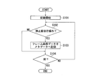
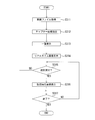
- FIG. 2 is a flowchart showing the moving image recording process.
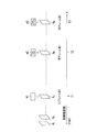
- FIG. 3 is a diagram showing an extracted frame image of moving image data to be recorded. With reference to FIGS. 2 and 3, still image storage during moving image recording will be described.
- the operator moves the scope distal end portion 110T while operating the video scope 110.
- the freeze button 118 is pressed. If it is determined by the operator that the freeze button 118 has been operated to store a still image (S102), the frame image at the time of the operation is recorded in the memory 123 or RAM 122 as metadata (S103).
- FIG. 3 shows a frame image when the operator operates the freeze button 118 three times for recording a still image during moving image recording.
- the J-th frame image AJ after time T1 has elapsed from the start of recording corresponds to an image when the scope distal end portion 110T reaches the observation target region and enters the visual field range.
- the operator saves a frame image as an image serving as a moving image reproduction start point (index).
- metadata relating to the frame image AJ is assigned to acquire an annotation.
- information on the scope type and image processing setting contents (such as contour emphasis) is added as metadata along with the frame number or time information from the start of the moving image, and is recorded in the moving image file.
- the frame image AJ is added as metadata m1 and recorded in the moving image file. That is, the frame image AJ itself is handled as the metadata m1.
- audio data, compressed moving image data, audio, moving image synchronization data, and the like are stored in a container serving as a main storage area, and metadata is stored in a predetermined area.
- metadata in addition to the description metadata such as the time from the start of recording, the frame number, and the like, a metadata area in which the user can arbitrarily define the format is defined, and the frame image specified by the operator operation Data is stored as metadata.
- the moving image recording system any system (for example, MP4, MXF format, etc.) can be adopted.
- the frame image AM of the Mth frame after the time T2 has elapsed from the start of recording is a frame image corresponding to the scene in which the video scope 110 captures the lesion, and the frame image AM is operated by the operator operating the freeze button 118. Is added as metadata m2 and recorded in the moving image file.
- the frame image AN of the Nth frame is a frame image corresponding to the scene when moving to a different part, is given as metadata m3, and is recorded in a moving image file. Steps S102 to S104 are repeatedly executed until a moving image recording end operation is performed using the keyboard 170 or the like (S104).
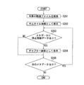
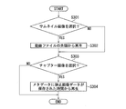
- FIG. 4 is a flowchart of the editing process before moving image playback.
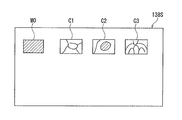
- FIG. 5 is a diagram showing an editing screen displayed on the LCD 136 of the front panel 126.
- FIG. 6 is a flowchart of the moving image reproduction start process. The selection and setting of the moving image playback start scene will be described with reference to FIGS.
- an editing screen as shown in FIG. 5 is displayed.
- a moving image file to be reproduced is retrieved by the operator (S201)
- the first frame image is displayed on the LCD 136 as a reduced image (hereinafter referred to as a thumbnail image) (S202).
- the scope type and image processing setting contents recorded as metadata can be displayed as character information. Then, it is determined whether or not frame image data exists in the metadata written in the searched moving image file (S203).
- the metadata is extracted and displayed on the LCD 136 as an image for editing (hereinafter referred to as a chapter image) (S204).
- a chapter image an image for editing
- steps S203 and S204 for all metadata S205
- a list of chapter images included in the metadata is displayed.
- the frame image data is not included in the metadata, only the thumbnail image is displayed, and character information indicating that it is not included is displayed.
- the thumbnail image M0 of the moving image first scene and the extracted chapter images C1, C2, and C3 are displayed on the editing screen.
- the chapter images C1, C2, and C3 correspond to the frame images AJ, AM, and AN of FIG.
- thumbnail image M0 of the first scene and the chapter images C1 to C3 are images of the same size, and the chapter images C1 to C3 are displayed in the order of the still image saving operation.
- the operator can select a series of chapter images C1 to C3 as moving image playback start points by operating the touch panel 138.
- the size of the thumbnail image M0 and the chapter images C1 to C3 may be different. By displaying the two images in different sizes, the operator can easily distinguish the thumbnail image M0 from the chapter images C1 to C3.
- the sizes of the chapter images C1 to C3 may be different from each other.
- the moving image starts to be reproduced on the monitor 150 from the first scene of the moving image file (S302).
- a chapter image is selected by the operator, a moving image is started to be reproduced from a scene corresponding to the selected chapter image (S303, S304). Specifically, based on the time from the start of recording or the frame number (for example, time T1, frame number J) recorded as metadata together with the chapter image, reproduction is started from the frame image corresponding to the chapter image.
- the endoscope apparatus 100 capable of moving image recording and reproduction display
- a frame corresponding to the scene at the time of operation is displayed.
- Images are recorded as metadata in a moving image file.
- an editing screen on which a moving image playback start scene can be selected is displayed on the LCD 136.
- metadata corresponding to the chapter image is extracted from the moving image file and displayed in a list on the editing screen.
- the still image data of one scene during moving image recording is recorded according to the operator's intention, it is possible to immediately grasp which scene is the chapter image displayed on the editing screen before playback display. Further, since frame image data is recorded as metadata in such a manner that it is embedded in a moving image file, it is possible to record moving images and still images without making them into separate files. Furthermore, since still image data is recorded as metadata in association with moving image data, it is easy to grasp what situation still image is recorded. In particular, it is possible to display a list of chapter images simply by searching for and extracting image data in the metadata, so that the display of the editing screen is not complicated.
- the moving image file is recorded not in the filing device 140 but in the memory in the processor 120, there is no need for a dedicated connection cable or command transmission. Further, since the scope type and the image processing setting content are also recorded as metadata, it becomes possible to grasp later the work situation at the time of moving image recording.
- the moving image playback may be started not from the frame image scene corresponding to the chapter image but from the preceding and succeeding scenes.
- a moving image recording process is performed in the operation of feeding the scope tip portion 110T to the observation target portion in the endoscope operation and observing the portion while gradually pulling back the scope tip portion 110T, a frame image several seconds before the chapter image is displayed.
- the reproduction can be started from the beginning so that the desired scene is not missed.
- the playback / display start scene may be corrected according to a predetermined number of shift frames or time with respect to the recording time or frame number metadata associated with the chapter image.
- frame image data may be extracted as a still image file from data of the entire moving image file instead of extracting still image data for each metadata.
- a step of still image file creation processing is executed instead of steps S203 to S205 of FIG.
- Real-time moving images (live images) and recorded moving images may be displayed on the monitor 150 at the same time.
- the simultaneous display mode can be set by the operator operating the keyboard 170.
- the frame image data may be recorded at a timing designated by the operator by a method other than the operator's scope button operation.
- the edit screen may be displayed on a display unit other than the processor, and may be configured to be displayed on the monitor 150, for example.
- the frame image data of the scene at the time of the operation may be recorded in the moving image file as metadata.
- the metadata may be data other than the frame image data.
- image data of the biological information monitoring device and filing device can be recorded, reproduced, and displayed as metadata.
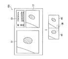
- FIG. 7 is a diagram showing a simultaneous display screen of live images and recorded images in the second embodiment.
- the biological information monitoring device 160 transmits the biological information display screen data displayed during the operation to the processor 120 as still image data.
- the processor 120 records the transmitted still image data as metadata in a moving image file. Note that a capture board (not shown) provided in the processor 120 may be used to capture still image data as a video signal.
- a biometric information display image recorded along with the chapter image is displayed together with the start of moving image recording / playback.
- FIG. 7 shows a real-time moving image I1, a recording / reproducing moving image I2, and a biological information display image I3 displayed on the monitor 150 during moving image reproduction.
- the operator can compare the medical condition of the current part with the past medical condition by starting reproduction and display from a scene in which the same part as the real-time moving image is displayed in the moving image file recorded in the past.
- the past biometric information display image on the monitor 150 it can be compared with the biometric information currently displayed on the dedicated monitor 165.
- the frame image data of the real-time image displayed at that time is recorded as metadata
- the frame image (reproduced frame image) of the recorded / reproduced moving image displayed at that time is recorded.
- the playback frame image data corresponding to the operation scene of the moving image data restored by the controller 144 is transmitted to the processor 120.
- a still image may be acquired from the filing device, the still image may be reproduced and displayed simultaneously with the real-time moving image, and the still image may be recorded as metadata.
- FIG. 7 shows real-time frame image data m5 and reproduction frame image data m6 to be recorded.
- real-time frame image data m5 and reproduction frame image data m6 are recorded as one metadata.
- character information CM of a predetermined comment may be recorded as an attached form. Thereby, the present and past states of the affected area can be compared and observed.
- a user may input a comment arbitrarily and preserve
- the recording and reproduction display as the metadata of the biological information image data may be applied to the reproduction display of only the recorded moving image as in the first embodiment.
- the reproduction and display of the reproduced moving image and the real-time moving image may be performed without recording and reproducing the biological information image data as metadata. In these cases, it may be recorded as metadata regardless of the frame image data of the real-time moving image.
- the present invention can also be applied to a device capable of outputting a video signal with an external peripheral device other than the biological information monitoring device.
- the present embodiment relates to an endoscope apparatus 100 that repeatedly reproduces a moving image around a time corresponding to a chapter selected by an operator. Description of parts common to the first embodiment is omitted.
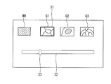
- FIG. 8 is a diagram showing an editing screen displayed on the LCD 136 of the front panel 126 according to the third embodiment.
- the operation when the thumbnail image M0 or the chapter images C1 to C3 is single-tapped by the operator is the same as that in the first embodiment.
- FIG. 8 shows an example of an image displayed on the LCD 136 when the chapter image C1 is double-tapped by the operator.
- the selected chapter image C1 is surrounded by a thick frame 31 to indicate that it is being selected.
- a moving image in a predetermined repetition time range is repeatedly reproduced and displayed around the time when the chapter image C1 is recorded.
- the repetition time is several seconds, for example, about 3 seconds.
- the area inside the thick frame 31 is an example of the reproducing unit of the present embodiment.
- the time bar 32 is displayed at the bottom of the screen.
- the total length of the time bar 32 indicates the repetition time.
- a cursor 33 is displayed on the time bar 32.
- the cursor 33 indicates the time when the image displayed in the thick frame 31 is captured within the range of the repetition time. Note that it may be possible for the operator to change the repetition time and the reproduction speed as appropriate by operating the keyboard 170 or the touch panel.
- the operator when an operator finds an important part such as a lesion, the operator operates the freeze button 118 to record a still image.
- the freeze button 118 when the freeze button 118 is operated, metadata such as a chapter image is recorded in the moving image file.
- the optimal image for diagnosis or the like is not always displayed at the time when the operator presses the freeze button. Further, in some cases, a moving image is easier to grasp, for example, a three-dimensional shape of a lesioned part than a still image.
- the operator can easily re-observe the part of interest at the time of endoscopy by repeatedly reproducing a short time moving image before and after the chapter image.
- FIG. 9 is a flowchart of image reproduction processing in the third embodiment. Steps S301 and S302 are the same as the processing of the first embodiment described with reference to FIG.
- the chapter image is selected in step S303 by single tap or double tap of the chapter image.
- any operation such as swipe, simultaneous tap with a plurality of fingers, drag and drop to a predetermined area, or keyboard operation can be used.
- step S303 When a chapter image is selected by a single tap (single tap in step S303), similarly to step S304 of the first embodiment, a moving image starts to be reproduced from a scene corresponding to the selected chapter image (step S304). ).
- step S303 When the chapter image is selected by double tap (double tap in step S303), the thick frame 31, the time bar 32, and the cursor 33 are displayed on the front panel 126 as described with reference to FIG. A moving image before and after the time when the selected chapter image is stored is repeatedly reproduced in the thick frame 31 (step S305). After the end of step S304 or step S305, the process ends.
- the moving image may be displayed in a greatly enlarged manner.
- the moving image may be displayed on a display device different from the front panel 126, for example, the monitor 150.
- processor 120 may return to step S301 in parallel while performing the moving image reproduction process of step S302, step S304, or step S305, and accept the next operation by the operator.
- an endoscope apparatus 100 that repeatedly reproduces a moving image of a short time before and after a chapter image.
- the operator can easily re-observe the part of interest during the endoscopy.
- the flowchart described using FIG. 6 or FIG. 9 may be executed by an information processing apparatus such as a general-purpose personal computer or tablet capable of reading a moving image file including metadata recorded during endoscopy.
- an information processing apparatus such as a general-purpose personal computer or tablet capable of reading a moving image file including metadata recorded during endoscopy.
- video files including metadata are recorded in a HIS (Hospital Information System) recording device connected via a network and installed in a room different from the endoscopy room It can be played back using a personal computer.
- HIS Local Information System
- the present embodiment relates to an endoscope apparatus 100 including a processor 120 that mainly operates based on software processing. Description of parts common to the first embodiment is omitted.
- FIG. 10 is a block diagram of an endoscope apparatus according to the fourth embodiment.
- the endoscope apparatus 100 includes a video scope 110, a processor 120, and a display device 90.
- the internal configuration of the video scope 110 is the same as that of the video scope 110 of Embodiment 1 described with reference to FIG.
- the display device 90 includes a display unit 91 and an input unit 92.
- the display unit 91 is a liquid crystal display panel, for example.
- the input unit 92 is a touch sensor that is disposed on the surface of the display unit 91 and constitutes a touch panel in conjunction with the display unit 91.
- the input unit 92 may be a keyboard or a mouse.
- the processor 120 includes a CPU 11, a main storage device 12, an auxiliary storage device 13, a communication unit 14, a display I / F (Interface) 15, an input I / F 16, a scope I / F 17, a light source 124, and a bus.
- the processor 120 according to the present embodiment is an example of an information processing apparatus that operates when the CPU 11 executes a program.
- the CPU 11 is an arithmetic control device that executes a program according to the present embodiment. As the CPU 11, one or a plurality of CPUs or a multi-core CPU is used. The CPU 11 is connected to each hardware part constituting the processor 120 via a bus.
- the main storage device 12 is a storage device such as SRAM (Static Random Access Memory), DRAM (Dynamic Random Access Memory), flash memory or the like.
- the main storage device 12 temporarily stores information necessary during the processing performed by the CPU 11 and a program being executed by the CPU 11.
- the auxiliary storage device 13 is a storage device such as SRAM, flash memory, hard disk or magnetic tape.
- the auxiliary storage device 13 stores a program to be executed by the CPU 11, a moving image file, and various types of information necessary for executing the program.
- the moving image file may be stored in an external mass storage device connected to the processor 120 via a network such as HIS.
- the communication unit 14 is an interface that performs communication with a network.
- the display I / F 15 is an interface that connects the display unit 91 and the bus.
- the input I / F is an interface that connects the input unit 92 and the bus.
- the scope I / F 17 is an interface that connects the video scope 110 and the bus.
- the scope I / F 17 is an example of an endoscope connection unit to which an endoscope is connected.
- the analog signal processing circuit 112, the timing controller 114, and the scope controller shown in FIG. 1 are connected to the bus via the scope I / F 17, respectively.
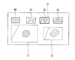
- FIG. 11 is an explanatory diagram for explaining a display screen in the fourth embodiment.
- the screen shown in FIG. 11 is displayed on the display unit 91.
- the screen shown in FIG. 11 includes a thumbnail image M0, chapter images C1, C2, and C3, a real-time moving image I1, and a recording / reproducing moving image I2. Note that the chapter images may be displayed in a list in two or more rows.
- the thumbnail image M0 and the chapter images C1, C2, and C3 include, for example, a thumbnail image and a chapter image extracted from a moving image file when a patient undergoing a similar endoscopic examination in the past. Is displayed.
- the thumbnail image C2 selected by the operator is surrounded by a thick frame 31.
- a reproduced image reproduced from the time when the chapter image surrounded by the thick frame 31 is recorded is displayed.
- a still image taken at the time when the chapter image was recorded may be displayed.
- a chapter image surrounded by a thick frame 31 may be enlarged and displayed on the recording / reproducing image I2.
- the area where the recording / reproducing image I2 is displayed is an example of the reproducing unit of the present embodiment.
- the moving image file may be selected from moving image files stored in the auxiliary storage device 13 based on an instruction from the operator.
- the moving image file may be acquired from the HIS based on an instruction from the operator and temporarily recorded in the auxiliary storage device 13.
- the moving image file may be automatically acquired from the HIS and recorded in the auxiliary storage device 13 based on the ID (Identifier) of the patient under examination. For example, in the case of a patient who performs follow-up observation by periodic endoscopy, the CPU 11 can select a moving image file recorded by the previous endoscopy based on the patient ID.
- the outline of the procedure for displaying the screen shown in FIG. 11 will be described.
- the operator selects a moving image file to be reproduced during the endoscopic examination or inputs information such as a patient ID necessary for the CPU 11 to select the video file.
- CPU11 extracts the chapter image from the metadata included in the moving image file and displays it.
- the CPU 11 displays the real-time moving image I1 based on the signal acquired from the video scope 110 via the scope I / F.
- the operator selects a chapter image to be compared with the real-time moving image I1 by an operation such as a single tap.
- the CPU 11 displays the recording / reproducing image I2 based on the chapter image that has received the selection.
- the operator can compare the change of the lesion site between the previous endoscopy and the current endoscopy.
- the operator can operate the video scope 110 to shoot a lesion from the same direction as the recorded / reproduced image I2, and compare the real-time moving image I1 thus captured with the recorded / reproduced image I2. The presence or absence of changes in the lesion can be observed in detail.
- the operator may select, for example, a moving image file obtained by capturing an endoscopic image of a healthy person.
- the operator can compare the endoscopic image of a healthy person displayed in the recording / reproducing image I2 with the real-time moving image I1.
- FIG. 12 is a flowchart showing a process flow of the fourth embodiment.
- CPU11 acquires a moving image file (step S311).
- the CPU 11 extracts a chapter image from the moving image file (step S312).
- the CPU 11 displays a list of the extracted chapter images as described with reference to FIG.
- the CPU 11 displays the real-time moving image I1 based on the signal acquired from the video scope 110 via the scope I / F (step S314). Note that the CPU 11 continues to update the real-time moving image I1 in parallel with the processing described below.
- the CPU 11 determines whether or not selection of any chapter image has been received from the chapter images displayed as a list (step S315).
- the CPU 11 displays the recorded / reproduced image I2 (step S316). When the recording / reproduction image I2 is a moving image, the CPU 11 continues to reproduce the recording / reproduction image I2 until selection is accepted again.
- the CPU 11 determines whether or not to end the process (step S317). For example, when the endoscopy ends, the CPU 11 determines to end the process. If it is determined that the process is to be ended (YES in step S317), the CPU 11 ends the process.
- step S317 If it is determined that the process is not terminated (NO in step S317), the CPU 11 returns to step S315.
- the endoscope apparatus 100 that displays the real-time image I1 and the recording / reproduction image selected by the operator side by side during the endoscopic examination.
- part of processing performed by the CPU may be executed by a dedicated circuit board connected to the bus.
- the CPU 11 may automatically select a chapter image similar to the real-time image I1 by processing such as image pattern matching.
Landscapes
- Physics & Mathematics (AREA)
- Health & Medical Sciences (AREA)
- Life Sciences & Earth Sciences (AREA)
- Surgery (AREA)
- Engineering & Computer Science (AREA)
- Optics & Photonics (AREA)
- Medical Informatics (AREA)
- General Health & Medical Sciences (AREA)
- Pathology (AREA)
- Nuclear Medicine, Radiotherapy & Molecular Imaging (AREA)
- Biomedical Technology (AREA)
- Heart & Thoracic Surgery (AREA)
- Biophysics (AREA)
- Molecular Biology (AREA)
- Animal Behavior & Ethology (AREA)
- Radiology & Medical Imaging (AREA)
- Public Health (AREA)
- Veterinary Medicine (AREA)
- Multimedia (AREA)
- Signal Processing (AREA)
- Astronomy & Astrophysics (AREA)
- General Physics & Mathematics (AREA)
- Endoscopes (AREA)
- Instruments For Viewing The Inside Of Hollow Bodies (AREA)
Abstract
内視鏡装置において、所望するシーンを容易に再生表示する。 動画像記録、再生表示が可能な内視鏡装置(100)において、動画像記録中にオペレータが静止画保存操作を行うと、操作時のシーンに応じたフレーム画像(チャプター画像)をメタデータとして動画ファイルに記録する。そして、動画像再生モード設定時、動画再生開始シーンを選択可能な編集画面をLCD(136)に表示する。このとき、チャプター画像相応のメタデータを動画ファイルから抽出し、編集画面に一覧表示する。オペレータが所望するチャプター画像を選択すると、そのチャプター画像のシーンから動画像を再生開始させる。
Description
本発明は、体内器官などを撮像し、必要に応じて処置等を行う内視鏡装置、情報処理装置およびプログラムに関し、特に、動画像の記録、再生処理に関する。
内視鏡装置では、観察中あるいは処置/手術中、スコープによって撮影される画像を動画像として記録することが可能である。オペレータが、スコープ操作部あるいはプロセッサのフロントパネルなどに設けられたボタンを押下すると、動画像データがプロセッサと接続する外部記録装置あるいはプロセッサ内部のメモリに送られ、動画ファイルとして記録される(例えば、特許文献1参照)。
手術などの作業開始から作業終了までの全期間に渡って動画像記録を行った場合、動画像再生時には、所望するシーンを効率よく抽出することが望まれる。そのため、記録された動画像データの中から特定シーンの動画像部分を抽出し、再生表示できるように構成されている(特許文献2参照)。
具体的には、対外から体内へスコープを挿入したときなど撮影画像に変化が生じた場合、その変化を検知し、動画像記録データに編集ポイントをメタ情報として付加し、また、画像の種別、電気メス装置など周辺機器の使用状況をメタ情報として関連付けて記録する。
動画像再生前の編集画面では、編集ポイントが付与された一連のサムネイル(縮小)画像とともに、メニュー画面で画像の種別を表す項目、周辺機器の使用状況を表す項目が表示される。オペレータが再生したいシーンの項目を選択、設定すると、そのシーンの編集ポイント画像が表示され、実行操作することによってその動画部分が再生される。
内視鏡装置側で自動的に再生開始(区切り)となるシーンを抽出する場合、動画像記録中どのシーンが抽出されたかオペレータにはわからない。そのため、動画像再生時において、文字情報で表示される項目と一連の抽出された映像シーンとを関連付けることが難しく、抽出されたシーンがどのシーンであるか直感的に理解しづらく、所望するシーンを見つけ出すことが難しい。
したがって、所望するシーンをオペレータが容易に見出して動画像を再生表示することが求められる。
本発明に係る内視鏡装置は、リアルタイムの動画像を動画ファイルとしてメモリに記録する記録処理部と、動画ファイルを読み出して動画像をモニタに再生表示する再生処理部と、再生開始シーンを選択可能な編集画面を表示部に表示する編集処理部とを備え、記録処理部が、動画像記録中、オペレータ指定のシーンに応じたフレーム画像(以下、チャプター画像)を、メタデータとして動画ファイルに保存し、編集処理部が、チャプター画像に応じたメタデータを抽出して、編集画面にチャプター画像を表示し、再生処理部が、オペレータに選択されたチャプター画像のシーンもしくはその前後のシーンから、動画像の再生を開始する。ここで、「前後のシーン」とは、チャプター画像から所定数(例えば数フレーム)のフレーム分だけ前あるいは後ろのフレーム画像を表し、ほぼ同じような被写体とみなせる範囲のフレーム画像を意味する。
例えば記録処理部は、オペレータによる静止画保存操作時のシーンに応じたチャプター画像を、メタデータとして動画ファイルに保存することができる。また、編集処理部は、メタデータの中にあるフレーム画像を、静止画ファイルとして取り出すことが可能である。
例えば記録処理部は、スコープの種類および画像処理設定内容の少なくともいずれか一方を、チャプター画像とともにメタデータとして動画ファイルに保存してもよい。また、編集処理部は、記録された動画像データの中で先頭シーンに応じた先頭フレーム画像を、チャプター画像とともに表示し、再生処理部が、オペレータによって先頭フレーム画像が選択されると、先頭フレーム画像から動画像の再生を開始することが可能である。
例えば内視鏡装置のプロセッサは、内視鏡作業関連映像を表示するととともに映像信号を出力可能な外部周辺機器と接続可能である。記録処理部は、オペレータによる静止画保存操作時に表示されていた内視鏡作業関連静止画像を、メタデータとして動画ファイルに保存することができる。再生処理部は、内視鏡作業関連静止画像に応じたメタデータを抽出し、内視鏡関連静止画像を動画像再生時に表示してもよい。
一方、内視鏡装置のプロセッサは、ファイリング装置と接続可能である。再生処理部は、リアルタイムの動画像とファイリング装置に記録された記録画像(静止画像、動画像いずれも含む)とを同時表示可能であり、記録処理部は、オペレータによる静止画保存操作時の再生シーンに応じた再生フレーム画像を、メタデータとして動画ファイルに保存することができる。
本発明の他の態様における内視鏡装置の記録・再生方法は、リアルタイムの動画像を動画ファイルとしてメモリに記録し、動画ファイルを読み出して動画像をモニタに再生表示し、再生開始シーンを選択可能な編集画面を表示部に表示する方法であって、動画像記録中、オペレータ指定のシーンに応じたフレーム画像(以下、チャプター画像)を、メタデータとして動画ファイルに保存し、チャプター画像に応じたメタデータを抽出して、編集画面にチャプター画像を表示し、オペレータに選択されたチャプター画像のシーンもしくはその前後のシーンから、動画像の再生を開始する。
一方、メタデータ記録の観点から導かれる内視鏡装置のプロセッサは、内視鏡作業関連映像を表示するととともに映像信号を出力可能な外部周辺機器と接続可能であり、リアルタイムの動画像を動画ファイルとしてメモリに記録する記録処理部を備える。そして、記録処理部が、動画像記録中、オペレータによる静止画保存操作時に表示されていた内視鏡作業関連静止画像を、メタデータとして動画ファイルに保存する。同様な技術的特徴を有する内視鏡装置のプロセッサは、ファイリング装置と接続可能であり、リアルタイムの動画像を動画ファイルとしてメモリに記録する記録処理部と、再生処理部は、リアルタイムの動画像とファイリング装置に記録された記録画像とを同時表示可能であり、記録処理部は、オペレータによる静止画保存操作時の再生シーンに応じた再生フレーム画像を、メタデータとして動画ファイルに保存する。
本発明の他の態様における情報処理装置は、動画像と、前記動画像の撮影中の所定の時刻に切り出されたチャプター画像に関するメタデータとを含む動画ファイルを取得する第1取得部と、前記第1取得部が取得した前記動画ファイルから抽出した前記チャプター画像を一覧表示する表示部と、前記表示部が一覧表示した前記チャプター画像からの選択を受け付ける受付部と、前記受付部が選択を受け付けた前記チャプター画像に対応する時刻に基づいて前記動画像を再生する再生部とを備える。
本発明の他の態様における情報処理装置は、前記動画像は、内視鏡を用いて撮影された画像であり、前期第1取得部は、前記内視鏡に設けられたボタンが操作された時刻に切り出されたチャプター画像に関するメタデータを含む動画ファイルを取得する。
本発明の他の態様における情報処理装置は、前記内視鏡が接続される内視鏡接続部と、前記内視鏡接続部を介して取得した動画像と時刻とに基づいて、前記動画ファイルを記録する記録部とを備える。
本発明の他の態様における情報処理装置は、撮影されたリアルタイム画像を取得する第2取得部を備え、前記表示部は、第2取得部が取得したリアルタイム画像と、前記チャプター画像または前記動画像とを同時に表示する。
本発明の他の態様におけるプログラムは、動画像と、前記動画像の撮影中の所定の時刻に切り出されたチャプター画像に関するメタデータとを含む動画ファイルを取得し、取得した前記動画ファイルから抽出した前記チャプター画像を一覧表示し、一覧表示した前記チャプター画像からの選択を受け付け、選択を受け付けたチャプター画像に対応する時刻に基づいて前記動画像を再生する処理をコンピュータに実行させる。
本発明によれば、内視鏡装置において、所望するシーンを容易に再生表示することができる。
[第1の実施形態]
以下、図面を参照して本発明の実施形態である内視鏡装置について説明する。
以下、図面を参照して本発明の実施形態である内視鏡装置について説明する。
図1は、第1の実施形態である内視鏡装置のブロック図である。
内視鏡装置100は、ビデオスコープ110とプロセッサ120とを備え、ビデオスコープ110は、プロセッサ120に着脱自在に接続可能である。またプロセッサ120には、モニタ150、キーボード170が接続されるとともに、ファイリング装置140、生体情報モニタリング装置160が接続されている。なお、ビデオスコープ110は、後述するようにイメージセンサ111を用いて消化管等の内部を観察する際に使用する、内視鏡の一例である。
プロセッサ120は、キセノンランプなどの光源124を備え、光源124から放射された光は、集光レンズ128を介してビデオスコープ110内に設けられたライトガイド117の入射端に入射する。ライトガイド117から射出した光は、配光レンズ119Aを介してスコープ先端部110Tから被写体(観察対象)に向けて照射される。光源124とライトガイド117との間には絞り129が設けられており、絞り129の開閉によって照明光量が調整される。
被写体で反射した照明光は、スコープ先端部110Tに設けられた対物レンズ119Bによって結像し、被写体像がイメージセンサ111の受光面に形成される。CMOSセンサ、あるいはCCDなどによって構成されるイメージセンサ111は駆動回路113によって駆動され、1フィールドもしくは1フレーム分の画素信号がイメージセンサ111から所定のフィールド/フレーム間隔(例えば1/60秒あるいは1/30秒間隔)で読み出される。イメージセンサ111の受光面上には、Cy、Ye、G、MgあるいはR、G、Bなどのカラーフィルタを配列させたカラーフィルタアレイ(図示せず)が配設されている。
イメージセンサ111から読み出された画素信号は、アナログ信号処理回路において増幅処理などが施されたさた後、プロセッサ120の信号処理回路125へ送られる。信号処理回路125では、デジタル画素信号に対し、色変換処理、ガンマ補正処理などの画像信号処理が施される。これにより、R、G、Bのカラー画像信号が生成される。
R,G,B画像信号は、RAMなどの画像メモリ(図示せず)に一時的に保存された後、後段信号処理回路135へ送られる。後段信号処理回路135では、オペレータの入力操作に伴う輪郭強調処理、スーパーインポーズ処理、あるいは複数の画像を同時表示するための編集処理などが施される。映像信号がモニタ150に出力されることにより、リアルタイムの観察画像が動画像としてモニタ150に表示される。
CPU(Central Processing Unit)などを含むシステムコントロール回路121は、タイミングコントローラ127、モータ130、後段信号処理回路135などへ制御信号を出力し、プロセッサ120の動作を制御する。動作制御プログラムは、あらかじめメモリ123に記憶されている。
スコープコントローラ115は、タイミングコントローラ114を制御するとともに、フリーズボタン118などからのボタン操作に応じて、システムコントロール回路121へ操作信号を送る。ビデオスコープ110がプロセッサ120に接続されると、ビデオスコープ110のメモリ116に記憶されたスコープ関連データが読み出され、プロセッサ120のRAM122に保存される。具体的には、スコープ機種名などのデータが読み出される。
ビデオスコープ110による撮像によって観察画像を表示する間、オペレータはキーボード170などに対する操作によって動画像を記録することが可能である。動画像記録操作が行われると、信号処理回路125において生成される各フレームの画像データは、システムコントロール回路121において圧縮処理され、RAM122に動画ファイルとして記録される。また、必要に応じてファイリング装置140へ出力される。ここでは、MPEG方式に従った動画圧縮処理が行われる。また、後述するように、オペレータが動画像記録中にフリーズボタン118を操作すると、その操作時のシーンのフレーム画像データがメタデータとして記録される。
プロセッサ120のフロントパネル126には、表示部としてLCD136が設けられており、LCD136の画面枠に合わせてタッチパネル138が設置されている。オペレータは、表示される輪郭強調用マーク、明るさレベルマークの部分をタッチすることで、画像処理、明るさ調整などが実行される。また、後述するように、動画像再生時、動画像再生開始シーンを選択可能な編集画面を表示可能である。
ファイリング装置140は、装置本体141と、ファイリングモニタ142とを備え、装置本体141は、コントローラ144と、メモリ145とを備えている。コントローラ144は、プロセッサ120から送られてくる画像データなどを受信し、ファイリングしてメモリ145に記録する。プロセッサ120から動画ファイル読み出しの指示があると、メモリ145から対象となる動画ファイルを読み出し、動画像データをプロセッサ120へ送信する。生体情報モニタリング装置160は、患者に取り付けられた各種センサからの信号に基づき、心拍数、脈拍、それらのパルス波形などを専用モニタ165に表示する。
図2は、動画像記録処理を示したフローチャートである。図3は、記録される動画像データの抽出フレーム画像を示した図である。図2、3を用いて、動画像記録時の静止画保存について説明する。
オペレータの操作によって動画像記録処理が開始されると(S101)、オペレータはビデオスコープ110を操作しながら、スコープ先端部110Tを移動させていく。そして、所望するシーンの観察画像が表示されると、フリーズボタン118を押下する。オペレータによって静止画保存のためフリーズボタン118が操作されたと判断されると(S102)、その操作時のフレーム画像をメタデータとしてメモリ123あるいはRAM122に記録する(S103)。
図3では、動画像記録中、オペレータが静止画保存のためにフリーズボタン118を3度操作したときのフレーム画像を示している。記録開始から時間T1経過したJ番目のフレーム画像AJは、スコープ先端部110Tが観察対象部位に到達し、視野範囲に入ったときの画像に相当する。オペレータは、動画像再生開始ポイント(指標)となる画像としてフレーム画像保存を行う。具体的には、フレーム画像AJに関するメタデータを付与し、アノテーションを取得させる。
このとき、フレーム番号あるいは動画開始からの時刻の情報とともに、スコープの種類、画像処理設定内容(輪郭強調など)の情報がメタデータとして付与され、動画ファイルに記録される。さらに本実施形態では、フレーム画像AJがメタデータm1として付与され、動画ファイルに記録される。すなわち、フレーム画像AJ自身がメタデータm1として扱われる。
動画ファイルでは、音声データ、圧縮動画データ、音声、動画の同期データなどがメインの格納領域となるコンテナに収納されるともに、メタデータが付随して所定領域に格納される。また、メタデータには、上述した記録開始からの時刻、フレーム番号などの記述メタデータとともに、ユーザが任意にフォーマットを規定できるメタデータの領域が定められており、オペレータ操作によって指定されたフレーム画像データが、メタデータとして格納される。動画記録方式は、任意の方式(例えばMP4、MXFフォーマットなど)を採用することが可能である。
記録開始から時間T2が経過したMフレーム目のフレーム画像AMは、ビデオスコープ110が病変部を捉えているシーンに応じたフレーム画像であり、オペレータがフリーズボタン118を操作することによって、フレーム画像AMがメタデータm2として付与され、動画ファイルに記録される。また、Nフレーム目のフレーム画像ANは、異なる部位に移動したときのシーンに応じたフレーム画像であり、メタデータm3として付与され、動画ファイルに記録される。キーボード170などによる動画像記録終了操作が行われるまで(S104)、ステップS102~S104が繰り返し実行される。
図4は、動画像再生前の編集処理のフローチャートである。図5は、フロントパネル126のLCD136に表示される編集画面を示した図である。図6は、動画再生開始処理のフローチャートである。図4~6を用いて、動画像再生開始シーンの選択、設定について説明する。
オペレータのキーボード170等による操作によって動画像再生モードが設定されると、図5に示すような編集画面が表示される。オペレータによって再生対象となる動画ファイルが検索されると(S201)、その先頭フレーム画像が縮小画像(以下、サムネイル画像という)としてLCD136に表示される(S202)。このとき、チャプター画像以外にメタデータとして記録されたスコープ種類、画像処理設定内容を文字情報で表示することが可能である。そして、検索された動画ファイルに書き込まれたメタデータの中に、フレーム画像データが存在するか否かが判断される(S203)。
フレーム画像データがメタデータとして存在する場合、そのメタデータを抽出し、編集用の画像(以下、チャプター画像という)としてLCD136に表示する(S204)。すべてのメタデータに対してステップS203、S204が実行されることによって(S205)、メタデータに含まれるチャプター画像が一覧表示される。ただし、メタデータにフレーム画像データが含まれない場合、サムネイル画像のみ表示され、含まれないことを示す文字情報が表示される。
図5では、編集画面において、動画先頭シーンのサムネイル画像M0と、抽出されたチャプター画像C1、C2、C3が表示されている。チャプター画像C1、C2、C3は、図3のフレーム画像AJ、AM、ANにそれぞれ対応する。
ここでは、先頭シーンのサムネイル画像M0と、チャプター画像C1~C3は同サイズのイメージであり、チャプター画像C1~C3は静止画保存操作の順番で並んで表示されている。オペレータは、タッチパネル138を操作することで、一連のチャプター画像C1~C3のシーンを、動画再生開始ポイントとして選択することができる。
なお、サムネイル画像M0とチャプター画像C1~C3とのサイズは、異なっていても良い。両者のサイズを異なるように表示することにより、オペレータがサムネイル画像M0とチャプター画像C1~C3とを容易に区別することができる。チャプター画像C1~C3同士のサイズは、相互に異なっていても良い。
オペレータがサムネイル画像を選択すると(図6のS301参照)、動画ファイルの先頭シーンから動画像がモニタ150に再生開始される(S302)。一方、オペレータによってチャプター画像が選択されると、選択されたチャプター画像に応じたシーンから動画像が再生開始される(S303、S304)。具体的には、チャプター画像とともにメタデータとして記録された記録開始からの時刻あるいはフレーム番号(例えば、時刻T1、フレーム番号J)に基づき、そのチャプター画像に応じたフレーム画像から再生開始される。
以上のように本実施形態によれば、動画像記録、再生表示が可能な内視鏡装置100において、動画像記録中にオペレータが静止画保存操作を行うと、操作時のシーンに応じたフレーム画像(チャプター画像)がメタデータとして動画ファイルに記録される。そして、動画像再生モード設定時には、動画再生開始シーンを選択可能な編集画面がLCD136に表示される。このとき、チャプター画像相応のメタデータが動画ファイルから抽出され、編集画面に一覧表示される。オペレータが所望するチャプター画像を選択すると、そのチャプター画像のシーンから動画像が再生開始される。
オペレータの意図に合わせて動画像記録中の1シーンの静止画像データを記録するため、再生表示前の編集画面に表示されるチャプター画像がどのシーンであるかすぐに把握することができる。また、フレーム画像データを動画像ファイルに埋め込むような形でメタデータとして記録するため、動画像、静止画像を別ファイル化することなく記録することができる。さらに、メタデータとして静止画像データが動画データと関連付けて記録されているため、どのような状況静止画を記録したのか把握するのが容易となる。特に、メタデータの中にある画像データを探索し、抽出するだけでチャプター画像を一覧表示することができるため、編集画面の表示も煩雑な処理を伴わない。
一方、動画ファイルがファイリング装置140ではなくプロセッサ120内のメモリに記録されるため、専用の接続ケーブル、コマンド送信など必要としない。また、スコープ種類、画像処理設定内容もメタデータとして記録されるため、動画記録時の作業状況などを後で把握することが可能となる。
なお、チャプター画像に応じたフレーム画像のシーンではなく、その前後のシーンから動画像再生開始させてもよい。例えば、内視鏡操作においてスコープ先端部110Tを観察対象部位まで送り込み、徐々にスコープ先端部110Tを引き戻しながら部位を観察する作業において動画像記録処理を行った場合、チャプター画像の数秒前のフレーム画像から再生開始させ、所望シーンを見逃さないようにすることができる。この場合、チャプター画像に付随する記録時刻あるいはフレーム番号のメタデータに対して、あらかじめ定めたシフトフレーム数あるいは時間によって再生表示開始シーンを修正すればよい。
なお、メタデータの中のフレーム画像データ抽出に関しては、メタデータごとに静止画像データを取り出すのではなく、動画ファイル全体のデータの中から、フレーム画像データを静止画ファイルとして取り出すようにしてもよい。この場合、図4のステップS203~S205の代わりに、静止画ファイル作成処理のステップが実行される。
リアルタイムの動画像(ライブ画像)と記録動画像とを、モニタ150に同時表示するようにしてもよい。例えば、オペレータがキーボード170を操作することにより、同時表示モードを設定することができる。また、オペレータのスコープボタン操作以外の手法によって、オペレータの指定するタイミングでフレーム画像データを記録してもよい。編集画面については、プロセッサ以外の表示部に表示してもよく、例えば、モニタ150に表示させるように構成してもよい。
オペレータが、キーボード170を用いて特定の入力操作を行った場合、又は、フットスイッチを操作した場合等に、その操作時のシーンのフレーム画像データがメタデータとして動画ファイルに記録されても良い。メタデータは、フレーム画像データ以外のデータでも良い。
[第2の実施形態]
次に、図7を用いて、第2の実施形態である内視鏡装置について説明する。第2の実施形態では、生体情報モニタリング装置およびファイリング装置の画像データをメタデータとして記録、再生表示することが可能である。
次に、図7を用いて、第2の実施形態である内視鏡装置について説明する。第2の実施形態では、生体情報モニタリング装置およびファイリング装置の画像データをメタデータとして記録、再生表示することが可能である。
図7は、第2の実施形態におけるライブ画像および記録画像の同時表示画面を示した図である。
第2の実施形態では、オペレータが静止画保存操作を行うと、その操作時のシーンに応じたフレーム画像データだけでなく、生体情報モニタリング装置160の専用モニタ165において操作時に表示されていた生体情報表示画像(静止画像)が、メタデータとして記録される。生体情報モニタリング装置160は、プロセッサ120から保存データ送信要求を受けると、操作時に表示されていた生体情報表示画面データを静止画像データとしてプロセッサ120へ送信する。プロセッサ120では、送られてきた静止画像データをメタデータとして動画ファイルに記録する。なお、プロセッサ120に設けられたキャプチャーボード(図示せず)を使い、静止画像データを映像信号として取り込むようにしてもよい。
そして、第1の実施形態の説明で示した編集画面でチャプター画像が選択された場合、そのチャプター画像に付随して記録された生体情報表示画像が、動画像記録再生開始とともに表示される。
図7では、動画像再生時のモニタ150に表示されるリアルタイム動画像I1、記録再生動画像I2、および生体情報表示画像I3を示している。オペレータは、過去に記録した動画ファイルの中でリアルタイム動画像と同じ部位を写し出したシーンから再生表示開始させることで、現在の部位の病状と過去の病状とを比較することができる。また、それとともに、過去の生体情報表示画像をモニタ150で確認することにより、今現在専用モニタ165に表示されている生体情報と比較することができる。
さらに、オペレータが静止画保存操作を行うと、そのとき表示されていたリアルタイム画像のフレーム画像データがメタデータとして記録されるとともに、そのとき表示されていた記録再生動画像のフレーム画像(再生フレーム画像)が合わせてメタデータとして記録される。ファイリング装置140では、コントローラ144にて復元された動画像データの操作時シーンに応じた再生フレーム画像データがプロセッサ120へ送信される。なお、ファイリング装置から静止画像を取得して、リアルタイム動画像と同時に静止画像を再生表示し、その静止画像をメタデータとして記録してもよい。
図7には、記録されるリアルタイムのフレーム画像データm5と再生フレーム画像データm6とを示している。ここでは、1つのメタデータとしてリアルタイムフレーム画像データm5、再生フレーム画像データm6が記録される。このとき、あらかじめ定められたコメントの文字情報CM(経過観察の確認お願いしますなど)を添付した形で記録してもよい。これにより、現在と過去の患部の状態を比較観察することができる。なお、コメントについては、ユーザが任意にコメントを入力してコメントデータを保存し、必要な場面でコメントを記録させてもよい。
なお、生体情報画像データのメタデータとしての記録および再生表示は、第1の実施形態のように記録された動画像のみの再生表示に適用してもよい。また、第2の実施形態において、生体情報画像データのメタデータとしての記録および再生を行わず、再生動画像とリアルタイムの動画像の再生表示のみ行ってもよい。これらの場合、リアルタイム動画像のフレーム画像データと関係なく、メタデータとして記録してもよい。また、生体情報モニタリング装置以外の外部周辺機器で映像信号出力可能な装置についても適用可能である。
[第3の実施形態]
本実施形態は、オペレータにより選択されたチャプターに対応する時刻付近の動画を繰り返し再生する内視鏡装置100に関する。第1の実施形態と共通する部分については、説明を省略する。
本実施形態は、オペレータにより選択されたチャプターに対応する時刻付近の動画を繰り返し再生する内視鏡装置100に関する。第1の実施形態と共通する部分については、説明を省略する。
図8は、第3の実施形態におけるフロントパネル126のLCD136に表示される編集画面を示した図である。オペレータにより、サムネイル画像M0又はチャプター画像C1からC3がシングルタップされた場合の動作は、第1の実施形態と同様である。
図8は、オペレータによりチャプター画像C1がダブルタップされた場合に、LCD136に表示される画像の例を示す。選択されたチャプター画像C1の周囲が太枠31により囲まれ、選択中であることが示される。
太枠31の内側に、チャプター画像C1が記録された時刻を中心にして、所定の繰り返し時間の範囲の動画像が繰り返し再生表示される。繰り返し時間は、数秒間、例えば3秒間程度である。太枠31の内側の領域は、本実施の形態の再生部の一例である。
画面の下部に、タイムバー32が表示される。タイムバー32の全長は、繰り返し時間を示す。タイムバー32にカーソル33が表示される。カーソル33は、繰り返し時間の範囲内で、太枠31に表示されている画像が撮影された時刻を示す。なお、オペレータがキーボード170又はタッチパネルを操作することにより、繰り返し時間および再生速度を適宜変更することが可能であっても良い。
内視鏡検査においては、オペレータは病変などの重要な部分を発見した際にフリーズボタン118を操作して静止画像を記録する。第1の実施形態において説明したとおり、フリーズボタン118が操作された場合に、動画像ファイルにチャプター画像等のメタデータが記録される。
しかしながら、オペレータがフリーズボタンを押した時刻に、必ずしも診断等に最適な画像が表示されているとは限らない。また、静止画像よりも動画像の方が、例えば病変部の立体的な形状等を把握しやすい場合がある。
図8に示すように、チャプター画像の前後の短い時間の動画像を繰り返し再生することにより、オペレータは内視鏡検査時に注目した部分の再観察を容易に行うことが可能である。
図9は、第3の実施形態における画像再生処理のフローチャートである。ステップS301およびステップS302は、図6を使用して説明した第1の実施形態の処理と同様であるので、説明を省略する。
本実施形態においては、ステップS303のチャプター画像の選択は、チャプター画像のシングルタップ又はダブルタップによって行われる。なお、シングルタップ又はダブルタップの代わりに、例えばスワイプ、複数の指による同時タップ、所定の領域へのドラッグアンドドロップ、又はキーボード操作等の、任意の操作を用いることができる。
シングルタップによってチャプター画像が選択された場合(ステップS303でシングルタップ)、第1の実施形態のステップS304と同様に、選択されたチャプター画像に応じたシーンから動画像が再生開始される(ステップS304)。
ダブルタップによってチャプター画像が選択された場合(ステップS303でダブルタップ)、図8を使用して説明したように、フロントパネル126に太枠31、タイムバー32及びカーソル33が表示される。太枠31内に、選択されたチャプター画像が保存された時刻の前後の動画像が繰り返し再生される(ステップS305)。ステップS304又はステップS305の終了後、処理は終了される。
動画像は、大きく拡大して表示されても良い。動画像は、フロントパネル126とは異なる表示装置、例えばモニタ150に表示されても良い。
なお、プロセッサ120は、ステップS302、ステップS304又はステップS305の動画像再生処理を行いながら、並行してステップS301に戻り、オペレータによる次の操作を受け付けても良い。
本実施の形態によると、チャプター画像の前後の短い時間の動画像を繰り返し再生する内視鏡装置100を提供できる。本実施の形態の内視鏡装置100を用いることにより、オペレータは内視鏡検査時に注目した部分の再観察を容易に行うことが可能である。
図6又は図9を使用して説明したフローチャートは、内視鏡検査中に記録されたメタデータを含む動画ファイルを読み込み可能な汎用のパソコン、タブレット等の情報処理装置で実行されても良い。例えば、メタデータを含む動画ファイルを、ネットワークを介して接続されたHIS(Hospital Information System:病院内情報システム)の記録装置に記録しておき、内視鏡検査室とは異なる部屋に設置されたパソコンを用いて、再生することができる。
[第4の実施形態]
本実施形態は、主にソフトウエア処理に基づいて動作するプロセッサ120を備える内視鏡装置100に関する。第1の実施形態と共通する部分については、説明を省略する。
本実施形態は、主にソフトウエア処理に基づいて動作するプロセッサ120を備える内視鏡装置100に関する。第1の実施形態と共通する部分については、説明を省略する。
図10は、第4の実施形態である内視鏡装置のブロック図である。内視鏡装置100は、ビデオスコープ110と、プロセッサ120と、表示装置90とを備える。ビデオスコープ110の内部の構成は、図1を使用して説明した実施の形態1のビデオスコープ110と同様であるので、図示を省略する。
表示装置90は、表示部91と入力部92とを備える。表示部91は、例えば液晶表示パネルである。入力部92は、表示部91の表面に配置されており、表示部91と連動してタッチパネルを構成するタッチセンサである。入力部92は、キーボード又はマウス等でも良い。
プロセッサ120は、CPU11、主記憶装置12、補助記憶装置13、通信部14、表示I/F(Interface)15、入力I/F16、スコープI/F17、光源124およびバスを備える。本実施の形態のプロセッサ120は、CPU11がプログラムを実行することにより動作する情報処理装置の一例である。
CPU11は、本実施の形態にかかるプログラムを実行する演算制御装置である。CPU11には、一又は複数のCPU又はマルチコアCPU等が使用される。CPU11は、バスを介してプロセッサ120を構成するハードウェア各部と接続されている。
主記憶装置12は、SRAM(Static Random Access Memory)、DRAM(Dynamic Random Access Memory)、フラッシュメモリ等の記憶装置である。主記憶装置12には、CPU11が行う処理の途中で必要な情報およびCPU11で実行中のプログラムが一時的に保存される。
補助記憶装置13は、SRAM、フラッシュメモリ、ハードディスク又は磁気テープ等の記憶装置である。補助記憶装置13には、CPU11に実行させるプログラム、動画ファイルおよびプログラムの実行に必要な各種情報が保存される。なお、動画ファイルはHIS等のネットワーク等を介してプロセッサ120に接続された外部の大容量記憶装置等に保存されていても良い。
通信部14は、ネットワークとの通信を行うインターフェイスである。表示I/F15は、表示部91とバスとを接続するインターフェイスである。入力I/Fは、入力部92とバスとを接続するインターフェイスである。スコープI/F17は、ビデオスコープ110とバスとを接続するインターフェイスである。スコープI/F17は、内視鏡が接続される内視鏡接続部の一例である。図1に示すアナログ信号処理回路112、タイミングコントローラ114およびスコープコントローラは、それぞれスコープI/F17を介してバスに接続される。
図11は、第4の実施形態における表示画面を説明する説明図である。図11に示す画面は、表示部91に表示される。図11に示す画面は、サムネイル画像M0と、チャプター画像C1、C2およびC3と、リアルタイム動画像I1と、記録再生動画像I2とを含む。なお、チャプター画像は、2行以上に並べて一覧表示されても良い。
リアルタイム動画像I1には、ビデオスコープ110のイメージセンサ111により撮影された画像がリアルタイムで表示される。サムネイル画像M0と、チャプター画像C1、C2およびC3には、例えば内視鏡検査中の患者が過去に同様の内視鏡検査を受けた際の動画ファイルから抽出されたサムネイル画像とチャプター画像とが表示される。オペレータにより選択されたサムネイル画像C2は、太枠31により囲まれている。
記録再生画像I2には、動画ファイルを太枠31で囲まれたチャプター画像が記録された時刻から再生した再生画像が表示される。記録再生画像I2には、チャプター画像が記録された時刻に撮影された静止画像が表示されても良い。記録再生画像I2には、太枠31で囲まれたチャプター画像が拡大表示されても良い。記録再生画像I2が表示される領域は、本実施の形態の再生部の一例である。
なお、動画ファイルは、オペレータの指示に基づいて、補助記憶装置13に蓄積された動画ファイルから選択されても良い。動画ファイルは、オペレータの指示に基づいてHISから取得されて補助記憶装置13に一時的に記録されても良い。動画ファイルは、検査中の患者のID(Identifier)等に基づいて、自動的にHISから取得されて補助記憶装置13に記録されても良い。例えば、定期的な内視鏡検査による経過観察を行う患者の場合には、患者IDに基づいてCPU11が前回の内視鏡検査で記録した動画ファイルを選択することができる。
図11に示す画面を表示する手順の概要を説明する。オペレータは、内視鏡検査を開始する前に、内視鏡検査中に再生する動画ファイルを選択するか、又はCPU11に選択させるために必要な患者ID等の情報をCPU11に入力する。
CPU11は、動画ファイルに含まれるメタデータから、チャプター画像を抽出して、表示する。オペレータが内視鏡検査を開始した場合、CPU11はスコープI/Fを介してビデオスコープ110から取得した信号に基づいて、リアルタイム動画像I1を表示する。
オペレータは、例えばシングルタップ等の操作により、リアルタイム動画像I1と対比確認したいチャプター画像を選択する。CPU11は、選択を受け付けたチャプター画像に基づいて、記録再生画像I2を表示する。
以上により、オペレータは例えば前回の内視鏡検査時と今回の内視鏡検査との病変部位の変化の様子を対比することができる。オペレータは、ビデオスコープ110を操作して、記録再生画像I2と同様の向きから病変部を撮影することができるこのようにして撮影したリアルタイム動画像I1と、記録再生画像I2とを比較することにより、病変の変化の有無等を詳細に観察することができる。
オペレータは、例えば健康な人の内視鏡画像を撮影した動画ファイルを選択しても良い。オペレータは、記録再生画像I2に表示した健康な人の内視鏡画像を、リアルタイム動画像I1と比較することができる。
図12は、第4の実施形態の処理の流れを示すフローチャートである。CPU11は、動画ファイルを取得する(ステップS311)。CPU11は、ステップS311により動画ファイルを取得する第1取得部の機能を実現する。CPU11は、動画ファイルからチャプター画像を抽出する(ステップS312)。CPU11は、抽出したチャプター画像を、図11を使用して説明したように一覧表示する。
CPU11はスコープI/Fを介してビデオスコープ110から取得した信号に基づいて、リアルタイム動画像I1を表示する(ステップS314)。なお、CPU11は以後に説明する処理と平行して、リアルタイム動画像I1を更新し続ける。CPU11は、ステップS314によりリアルタイム画像を取得する第2取得部の機能を実現する。
CPU11は一覧表示したチャプター画像から、いずれかのチャプター画像の選択を受け付けたか否かを判定する(ステップS315)。CPU11は、ステップS315によりチャプター画像の選択を受け付ける受付部の機能を実現する。受け付けたと判定した場合(ステップS315でYES)。CPU11は記録再生画像I2を表示する(ステップS316)。なお、記録再生画像I2が動画像である場合には、CPU11は再度選択を受け付けるまで、記録再生画像I2の再生を継続する。
CPU11は、処理を終了するか否かを判定する(ステップS317)。例えば、内視鏡検査が終了した場合に、CPU11は処理を終了すると判定する。処理を終了すると判定した場合(ステップS317でYES)、CPU11は処理を終了する。
処理を終了しないと判定した場合(ステップS317でNO)、CPU11はステップS315に戻る。
本実施の形態によると、内視鏡検査中に、リアルタイム画像I1とオペレータが選択した記録再生画像とを並べて表示する内視鏡装置100を提供できる。
例えば画像処理等の、CPUが行う処理の一部を、バスに接続された専用の回路基板で実行しても良い。
CPU11は、画像のパターンマッチング等の処理により、リアルタイム画像I1と類似するチャプター画像を自動的に選択しても良い。
各実施例で記載されている技術的特徴(構成要件)はお互いに組合せ可能であり、組み合わせすることにより、新しい技術的特徴を形成することができる。
今回開示された実施の形態はすべての点で例示であって、制限的なものではないと考えられるべきである。本発明の範囲は、上記した意味ではなく、請求の範囲によって示され、請求の範囲と均等の意味および範囲内でのすべての変更が含まれることが意図される。
今回開示された実施の形態はすべての点で例示であって、制限的なものではないと考えられるべきである。本発明の範囲は、上記した意味ではなく、請求の範囲によって示され、請求の範囲と均等の意味および範囲内でのすべての変更が含まれることが意図される。
11 CPU
12 主記憶装置
13 補助記憶装置
14 通信部
15 表示I/F
16 入力I/F
17 スコープI/F 31 太枠
32 タイムバー
33 カーソル
100 内視鏡装置
110 ビデオスコープ(ビデオスコープ、内視鏡)
120 プロセッサ
121 システムコントロール回路(編集処理部、再生処理部)
135 後段信号処理回路(編集処理部、再生処理部、記録処理部)
136 LCD(表示部)
150 モニタ
12 主記憶装置
13 補助記憶装置
14 通信部
15 表示I/F
16 入力I/F
17 スコープI/F 31 太枠
32 タイムバー
33 カーソル
100 内視鏡装置
110 ビデオスコープ(ビデオスコープ、内視鏡)
120 プロセッサ
121 システムコントロール回路(編集処理部、再生処理部)
135 後段信号処理回路(編集処理部、再生処理部、記録処理部)
136 LCD(表示部)
150 モニタ
Claims (14)
- リアルタイムの動画像を動画ファイルとしてメモリに記録する記録処理部と、
前記動画ファイルを読み出して動画像をモニタに再生表示する再生処理部と、
再生開始シーンを選択可能な編集画面を表示部に表示する編集処理部とを備え、
前記記録処理部が、動画像記録中、オペレータ指定のシーンに応じたフレーム画像(以下、チャプター画像)を、メタデータとして前記動画ファイルに保存し、
前記編集処理部が、チャプター画像に応じたメタデータを抽出して、編集画面にチャプター画像を表示し、
前記再生処理部が、オペレータに選択されたチャプター画像のシーンもしくはその前後のシーンから、動画像の再生を開始することを特徴とする内視鏡装置。 - 前記記録処理部が、オペレータによる静止画保存操作時のシーンに応じたチャプター画像を、メタデータとして前記動画ファイルに保存することを特徴とする請求項1に記載の内視鏡装置。
- 前記編集処理部が、メタデータの中にあるフレーム画像を、静止画ファイルとして取り出すことを特徴とする請求項1又は2に記載の内視鏡装置。
- 前記記録処理部が、スコープの種類および画像処理設定内容の少なくともいずれか一方を、チャプター画像とともにメタデータとして前記動画ファイルに保存することを特徴とする請求項1乃至3のいずれかに記載の内視鏡装置。
- 前記編集処理部が、記録された動画像データの中で先頭シーンに応じた先頭フレーム画像を、チャプター画像とともに表示し、
前記再生処理部が、オペレータによって先頭フレーム画像が選択されると、先頭フレーム画像から動画像の再生を開始することを特徴とする請求項1乃至4のいずれかに記載の内視鏡装置。 - 前記内視鏡装置のプロセッサが、内視鏡作業関連映像を表示するととともに映像信号を出力可能な外部周辺機器と接続可能であり、
前記記録処理部が、オペレータによる静止画保存操作時に表示されていた内視鏡作業関連静止画像を、メタデータとして前記動画ファイルに保存することを特徴とする請求項1乃至5のいずれかに記載の内視鏡装置。 - 前記再生処理部が、内視鏡作業関連静止画像に応じたメタデータを抽出し、内視鏡関連静止画像を動画像再生時に表示することを特徴とする請求項6に記載の内視鏡装置。
- 前記内視鏡装置のプロセッサが、ファイリング装置と接続可能であり、
前記再生処理部が、リアルタイムの動画像と前記ファイリング装置に記録された記録画像とを同時表示可能であり、
前記記録処理部が、オペレータによる静止画保存操作時の再生シーンに応じた再生フレーム画像を、メタデータとして前記動画ファイルに保存することを特徴とする請求項1乃至7のいずれかに記載の内視鏡装置。 - リアルタイムの動画像を動画ファイルとしてメモリに記録し、
前記動画ファイルを読み出して動画像をモニタに再生表示し、
再生開始シーンを選択可能な編集画面を表示部に表示する方法であって、
動画像記録中、オペレータ指定のシーンに応じたチャプター画像を、メタデータとして前記動画ファイルに保存し、
チャプター画像に応じたメタデータを抽出して、編集画面にチャプター画像を表示し、
オペレータに選択されたチャプター画像のシーンもしくはその前後のシーンから、動画像の再生を開始することを特徴とする内視鏡装置の記録・再生方法。 - 動画像と、前記動画像の撮影中の所定の時刻に切り出されたチャプター画像に関するメタデータとを含む動画ファイルを取得する第1取得部と、
前記第1取得部が取得した前記動画ファイルから抽出した前記チャプター画像を一覧表示する表示部と、
前記表示部が一覧表示した前記チャプター画像からの選択を受け付ける受付部と、
前記受付部が選択を受け付けた前記チャプター画像に対応する時刻に基づいて前記動画像を再生する再生部とを備える
情報処理装置。 - 前記動画像は、内視鏡を用いて撮影された画像であり、
前期第1取得部は、前記内視鏡に設けられたボタンが操作された時刻に切り出されたチャプター画像に関するメタデータを含む動画ファイルを取得する
請求項10に記載の情報処理装置。 - 前記内視鏡が接続される内視鏡接続部と、
前記内視鏡接続部を介して取得した動画像と時刻とに基づいて、前記動画ファイルを記録する記録部とを備える
請求項11に記載の情報処理装置。 - 撮影されたリアルタイム画像を取得する第2取得部を備え、
前記表示部は、第2取得部が取得したリアルタイム画像と、前記チャプター画像または前記動画像とを同時に表示する
請求項10から請求項12のいずれか一つに記載の情報処理装置。 - 動画像と、前記動画像の撮影中の所定の時刻に切り出されたチャプター画像に関するメタデータとを含む動画ファイルを取得し、
取得した前記動画ファイルから抽出した前記チャプター画像を一覧表示し、
一覧表示した前記チャプター画像からの選択を受け付け、
選択を受け付けたチャプター画像に対応する時刻に基づいて前記動画像を再生する
処理をコンピュータに実行させるプログラム。
Priority Applications (2)
| Application Number | Priority Date | Filing Date | Title |
|---|---|---|---|
| JP2018537357A JPWO2018043585A1 (ja) | 2016-08-31 | 2017-08-30 | 内視鏡装置、内視鏡装置の記録・再生方法、情報処理装置およびプログラム |
| CN201780035270.8A CN109310300A (zh) | 2016-08-31 | 2017-08-30 | 内窥镜装置、信息处理装置以及程序 |
Applications Claiming Priority (2)
| Application Number | Priority Date | Filing Date | Title |
|---|---|---|---|
| JP2016-169443 | 2016-08-31 | ||
| JP2016169443 | 2016-08-31 |
Publications (1)
| Publication Number | Publication Date |
|---|---|
| WO2018043585A1 true WO2018043585A1 (ja) | 2018-03-08 |
Family
ID=61301046
Family Applications (1)
| Application Number | Title | Priority Date | Filing Date |
|---|---|---|---|
| PCT/JP2017/031220 Ceased WO2018043585A1 (ja) | 2016-08-31 | 2017-08-30 | 内視鏡装置、情報処理装置およびプログラム |
Country Status (3)
| Country | Link |
|---|---|
| JP (1) | JPWO2018043585A1 (ja) |
| CN (1) | CN109310300A (ja) |
| WO (1) | WO2018043585A1 (ja) |
Cited By (5)
| Publication number | Priority date | Publication date | Assignee | Title |
|---|---|---|---|---|
| JP2020089611A (ja) * | 2018-12-07 | 2020-06-11 | コニカミノルタ株式会社 | 画像表示装置、画像表示方法及び画像表示プログラム |
| CN111936033A (zh) * | 2018-04-10 | 2020-11-13 | 奥林巴斯株式会社 | 医疗系统 |
| CN113365545A (zh) * | 2019-02-13 | 2021-09-07 | 奥林巴斯株式会社 | 图像记录装置、图像记录方法和图像记录程序 |
| EP4091529A1 (en) | 2021-05-21 | 2022-11-23 | FUJI-FILM Corporation | Medical image processing system and method for operating the same |
| WO2024223514A1 (de) * | 2023-04-24 | 2024-10-31 | Karl Storz Se & Co. Kg | Aufzeichnungsvorrichtung zur medizinischen bilddatenerfassung |
Families Citing this family (2)
| Publication number | Priority date | Publication date | Assignee | Title |
|---|---|---|---|---|
| WO2021176852A1 (ja) * | 2020-03-03 | 2021-09-10 | 富士フイルム株式会社 | 画像選択支援装置、画像選択支援方法、及び画像選択支援プログラム |
| WO2022186111A1 (ja) * | 2021-03-04 | 2022-09-09 | 富士フイルム株式会社 | 医用画像処理装置、医用画像処理方法、及びプログラム |
Citations (6)
| Publication number | Priority date | Publication date | Assignee | Title |
|---|---|---|---|---|
| JP2000312663A (ja) * | 1999-04-30 | 2000-11-14 | Asahi Optical Co Ltd | 電子内視鏡装置 |
| JP2006271870A (ja) * | 2005-03-30 | 2006-10-12 | Olympus Medical Systems Corp | 内視鏡用画像処理装置 |
| JP2010220794A (ja) * | 2009-03-24 | 2010-10-07 | Fujifilm Corp | 内視鏡画像回転装置および方法並びにプログラム |
| JP2012099979A (ja) * | 2010-10-29 | 2012-05-24 | Keyence Corp | 動画像撮像装置、動画像観察方法、動画像観察プログラム及びコンピュータで読取可能な記録媒体 |
| JP2016053833A (ja) * | 2014-09-03 | 2016-04-14 | オリンパス株式会社 | 情報処理システム |
| WO2016084779A1 (ja) * | 2014-11-27 | 2016-06-02 | オリンパス株式会社 | 画像再生装置および画像再生プログラム |
Family Cites Families (3)
| Publication number | Priority date | Publication date | Assignee | Title |
|---|---|---|---|---|
| JP4531416B2 (ja) * | 2004-02-20 | 2010-08-25 | Hoya株式会社 | 内視鏡システム |
| US9046757B2 (en) * | 2010-10-29 | 2015-06-02 | Keyence Corporation | Moving image pickup apparatus, method for observing moving image, moving image observing program, and computer-readable recording medium |
| JP2012254182A (ja) * | 2011-06-09 | 2012-12-27 | Hoya Corp | 画像処理装置、画像ファイル保存方法、画像ファイル保存プログラム、及び電子内視鏡システム |
-
2017
- 2017-08-30 WO PCT/JP2017/031220 patent/WO2018043585A1/ja not_active Ceased
- 2017-08-30 JP JP2018537357A patent/JPWO2018043585A1/ja active Pending
- 2017-08-30 CN CN201780035270.8A patent/CN109310300A/zh active Pending
Patent Citations (6)
| Publication number | Priority date | Publication date | Assignee | Title |
|---|---|---|---|---|
| JP2000312663A (ja) * | 1999-04-30 | 2000-11-14 | Asahi Optical Co Ltd | 電子内視鏡装置 |
| JP2006271870A (ja) * | 2005-03-30 | 2006-10-12 | Olympus Medical Systems Corp | 内視鏡用画像処理装置 |
| JP2010220794A (ja) * | 2009-03-24 | 2010-10-07 | Fujifilm Corp | 内視鏡画像回転装置および方法並びにプログラム |
| JP2012099979A (ja) * | 2010-10-29 | 2012-05-24 | Keyence Corp | 動画像撮像装置、動画像観察方法、動画像観察プログラム及びコンピュータで読取可能な記録媒体 |
| JP2016053833A (ja) * | 2014-09-03 | 2016-04-14 | オリンパス株式会社 | 情報処理システム |
| WO2016084779A1 (ja) * | 2014-11-27 | 2016-06-02 | オリンパス株式会社 | 画像再生装置および画像再生プログラム |
Cited By (5)
| Publication number | Priority date | Publication date | Assignee | Title |
|---|---|---|---|---|
| CN111936033A (zh) * | 2018-04-10 | 2020-11-13 | 奥林巴斯株式会社 | 医疗系统 |
| JP2020089611A (ja) * | 2018-12-07 | 2020-06-11 | コニカミノルタ株式会社 | 画像表示装置、画像表示方法及び画像表示プログラム |
| CN113365545A (zh) * | 2019-02-13 | 2021-09-07 | 奥林巴斯株式会社 | 图像记录装置、图像记录方法和图像记录程序 |
| EP4091529A1 (en) | 2021-05-21 | 2022-11-23 | FUJI-FILM Corporation | Medical image processing system and method for operating the same |
| WO2024223514A1 (de) * | 2023-04-24 | 2024-10-31 | Karl Storz Se & Co. Kg | Aufzeichnungsvorrichtung zur medizinischen bilddatenerfassung |
Also Published As
| Publication number | Publication date |
|---|---|
| CN109310300A (zh) | 2019-02-05 |
| JPWO2018043585A1 (ja) | 2019-03-07 |
Similar Documents
| Publication | Publication Date | Title |
|---|---|---|
| WO2018043585A1 (ja) | 内視鏡装置、情報処理装置およびプログラム | |
| US9186041B2 (en) | Medical information recording apparatus that determines medical scene or changing of medical scene, synthesizes images obtained by medical equipment, and records synthesized image | |
| JP4971615B2 (ja) | 生体内でキャプチャされた画像ストリームを編集するシステムおよび方法 | |
| EP2014219A2 (en) | Endoscopic image processing apparatus | |
| US9411932B2 (en) | Image management apparatus | |
| US20090131746A1 (en) | Capsule endoscope system and method of processing image data thereof | |
| US10015436B2 (en) | Image playback apparatus and computer-readable recording medium | |
| JP5368668B2 (ja) | 医用画像表示装置、医用画像表示システム及び医用画像表示システムの作動方法 | |
| CN101686799A (zh) | 图像处理装置、该图像处理装置的动作方法以及程序 | |
| EP2704439A1 (en) | Medical image recording apparatus, recording method of the same, and medical image recording program | |
| JP2011036372A (ja) | 医療画像記録装置 | |
| US20170303767A1 (en) | Endoscope for storing images | |
| JP5451718B2 (ja) | 医用画像表示装置、医用画像表示システム及び医用画像表示システムの作動方法 | |
| JP2009022446A (ja) | 医療における統合表示のためのシステム及び方法 | |
| JP4477451B2 (ja) | 画像表示装置、画像表示方法および画像表示プログラム | |
| WO2016072288A1 (ja) | 内視鏡装置、および、内視鏡装置の動作方法、並びにプログラム | |
| JP4716794B2 (ja) | 画像表示装置 | |
| JP2005040223A (ja) | 医療用画像表示装置 | |
| JP2005103030A (ja) | 医療画像作成装置及び医療画像作成プログラム | |
| JP2022068439A (ja) | 検査支援装置、検査支援方法および検査支援プログラム | |
| JP2005124824A (ja) | 手術支援システム | |
| JP4964572B2 (ja) | 動画記録再生装置 | |
| JP2008264313A (ja) | 内視鏡システム | |
| JP2018007960A (ja) | 内視鏡装置 | |
| JP7641920B2 (ja) | 内視鏡用プロセッサ、情報処理方法及びコンピュータプログラム |
Legal Events
| Date | Code | Title | Description |
|---|---|---|---|
| WWE | Wipo information: entry into national phase |
Ref document number: 2018537357 Country of ref document: JP |
|
| 121 | Ep: the epo has been informed by wipo that ep was designated in this application |
Ref document number: 17846589 Country of ref document: EP Kind code of ref document: A1 |
|
| NENP | Non-entry into the national phase |
Ref country code: DE |
|
| 122 | Ep: pct application non-entry in european phase |
Ref document number: 17846589 Country of ref document: EP Kind code of ref document: A1 |