WO2018043248A1 - Stabilizer manufacturing method, and joint structure for stabilizer link - Google Patents
Stabilizer manufacturing method, and joint structure for stabilizer link Download PDFInfo
- Publication number
- WO2018043248A1 WO2018043248A1 PCT/JP2017/030140 JP2017030140W WO2018043248A1 WO 2018043248 A1 WO2018043248 A1 WO 2018043248A1 JP 2017030140 W JP2017030140 W JP 2017030140W WO 2018043248 A1 WO2018043248 A1 WO 2018043248A1
- Authority
- WO
- WIPO (PCT)
- Prior art keywords
- stabilizer
- stud
- ball
- link
- hole
- Prior art date
Links
Images


Classifications
-
- B—PERFORMING OPERATIONS; TRANSPORTING
- B60—VEHICLES IN GENERAL
- B60G—VEHICLE SUSPENSION ARRANGEMENTS
- B60G21/00—Interconnection systems for two or more resiliently-suspended wheels, e.g. for stabilising a vehicle body with respect to acceleration, deceleration or centrifugal forces
- B60G21/02—Interconnection systems for two or more resiliently-suspended wheels, e.g. for stabilising a vehicle body with respect to acceleration, deceleration or centrifugal forces permanently interconnected
- B60G21/04—Interconnection systems for two or more resiliently-suspended wheels, e.g. for stabilising a vehicle body with respect to acceleration, deceleration or centrifugal forces permanently interconnected mechanically
- B60G21/05—Interconnection systems for two or more resiliently-suspended wheels, e.g. for stabilising a vehicle body with respect to acceleration, deceleration or centrifugal forces permanently interconnected mechanically between wheels on the same axle but on different sides of the vehicle, i.e. the left and right wheel suspensions being interconnected
- B60G21/055—Stabiliser bars
- B60G21/0551—Mounting means therefor
-
- B—PERFORMING OPERATIONS; TRANSPORTING
- B60—VEHICLES IN GENERAL
- B60G—VEHICLE SUSPENSION ARRANGEMENTS
- B60G21/00—Interconnection systems for two or more resiliently-suspended wheels, e.g. for stabilising a vehicle body with respect to acceleration, deceleration or centrifugal forces
- B60G21/02—Interconnection systems for two or more resiliently-suspended wheels, e.g. for stabilising a vehicle body with respect to acceleration, deceleration or centrifugal forces permanently interconnected
- B60G21/04—Interconnection systems for two or more resiliently-suspended wheels, e.g. for stabilising a vehicle body with respect to acceleration, deceleration or centrifugal forces permanently interconnected mechanically
- B60G21/05—Interconnection systems for two or more resiliently-suspended wheels, e.g. for stabilising a vehicle body with respect to acceleration, deceleration or centrifugal forces permanently interconnected mechanically between wheels on the same axle but on different sides of the vehicle, i.e. the left and right wheel suspensions being interconnected
- B60G21/055—Stabiliser bars
-
- B—PERFORMING OPERATIONS; TRANSPORTING
- B60—VEHICLES IN GENERAL
- B60G—VEHICLE SUSPENSION ARRANGEMENTS
- B60G7/00—Pivoted suspension arms; Accessories thereof
- B60G7/005—Ball joints
-
- F—MECHANICAL ENGINEERING; LIGHTING; HEATING; WEAPONS; BLASTING
- F16—ENGINEERING ELEMENTS AND UNITS; GENERAL MEASURES FOR PRODUCING AND MAINTAINING EFFECTIVE FUNCTIONING OF MACHINES OR INSTALLATIONS; THERMAL INSULATION IN GENERAL
- F16C—SHAFTS; FLEXIBLE SHAFTS; ELEMENTS OR CRANKSHAFT MECHANISMS; ROTARY BODIES OTHER THAN GEARING ELEMENTS; BEARINGS
- F16C11/00—Pivots; Pivotal connections
- F16C11/04—Pivotal connections
- F16C11/06—Ball-joints; Other joints having more than one degree of angular freedom, i.e. universal joints
- F16C11/0604—Construction of the male part
-
- F—MECHANICAL ENGINEERING; LIGHTING; HEATING; WEAPONS; BLASTING
- F16—ENGINEERING ELEMENTS AND UNITS; GENERAL MEASURES FOR PRODUCING AND MAINTAINING EFFECTIVE FUNCTIONING OF MACHINES OR INSTALLATIONS; THERMAL INSULATION IN GENERAL
- F16C—SHAFTS; FLEXIBLE SHAFTS; ELEMENTS OR CRANKSHAFT MECHANISMS; ROTARY BODIES OTHER THAN GEARING ELEMENTS; BEARINGS
- F16C11/00—Pivots; Pivotal connections
- F16C11/04—Pivotal connections
- F16C11/06—Ball-joints; Other joints having more than one degree of angular freedom, i.e. universal joints
- F16C11/0695—Mounting of ball-joints, e.g. fixing them to a connecting rod
-
- B—PERFORMING OPERATIONS; TRANSPORTING
- B60—VEHICLES IN GENERAL
- B60G—VEHICLE SUSPENSION ARRANGEMENTS
- B60G2202/00—Indexing codes relating to the type of spring, damper or actuator
- B60G2202/10—Type of spring
- B60G2202/13—Torsion spring
- B60G2202/135—Stabiliser bar and/or tube
-
- B—PERFORMING OPERATIONS; TRANSPORTING
- B60—VEHICLES IN GENERAL
- B60G—VEHICLE SUSPENSION ARRANGEMENTS
- B60G2204/00—Indexing codes related to suspensions per se or to auxiliary parts
- B60G2204/10—Mounting of suspension elements
- B60G2204/12—Mounting of springs or dampers
- B60G2204/122—Mounting of torsion springs
- B60G2204/1224—End mounts of stabiliser on wheel suspension
-
- B—PERFORMING OPERATIONS; TRANSPORTING
- B60—VEHICLES IN GENERAL
- B60G—VEHICLE SUSPENSION ARRANGEMENTS
- B60G2204/00—Indexing codes related to suspensions per se or to auxiliary parts
- B60G2204/40—Auxiliary suspension parts; Adjustment of suspensions
- B60G2204/416—Ball or spherical joints
-
- B—PERFORMING OPERATIONS; TRANSPORTING
- B60—VEHICLES IN GENERAL
- B60G—VEHICLE SUSPENSION ARRANGEMENTS
- B60G2204/00—Indexing codes related to suspensions per se or to auxiliary parts
- B60G2204/40—Auxiliary suspension parts; Adjustment of suspensions
- B60G2204/422—Links for mounting suspension elements
-
- B—PERFORMING OPERATIONS; TRANSPORTING
- B60—VEHICLES IN GENERAL
- B60G—VEHICLE SUSPENSION ARRANGEMENTS
- B60G2206/00—Indexing codes related to the manufacturing of suspensions: constructional features, the materials used, procedures or tools
- B60G2206/01—Constructional features of suspension elements, e.g. arms, dampers, springs
- B60G2206/40—Constructional features of dampers and/or springs
- B60G2206/42—Springs
- B60G2206/427—Stabiliser bars or tubes
-
- B—PERFORMING OPERATIONS; TRANSPORTING
- B60—VEHICLES IN GENERAL
- B60G—VEHICLE SUSPENSION ARRANGEMENTS
- B60G2206/00—Indexing codes related to the manufacturing of suspensions: constructional features, the materials used, procedures or tools
- B60G2206/01—Constructional features of suspension elements, e.g. arms, dampers, springs
- B60G2206/80—Manufacturing procedures
- B60G2206/82—Joining
- B60G2206/8201—Joining by welding
-
- B—PERFORMING OPERATIONS; TRANSPORTING
- B60—VEHICLES IN GENERAL
- B60G—VEHICLE SUSPENSION ARRANGEMENTS
- B60G2206/00—Indexing codes related to the manufacturing of suspensions: constructional features, the materials used, procedures or tools
- B60G2206/01—Constructional features of suspension elements, e.g. arms, dampers, springs
- B60G2206/80—Manufacturing procedures
- B60G2206/82—Joining
- B60G2206/8209—Joining by deformation
- B60G2206/82092—Joining by deformation by press-fitting
-
- B—PERFORMING OPERATIONS; TRANSPORTING
- B60—VEHICLES IN GENERAL
- B60G—VEHICLE SUSPENSION ARRANGEMENTS
- B60G2206/00—Indexing codes related to the manufacturing of suspensions: constructional features, the materials used, procedures or tools
- B60G2206/01—Constructional features of suspension elements, e.g. arms, dampers, springs
- B60G2206/80—Manufacturing procedures
- B60G2206/82—Joining
- B60G2206/821—Joining by gluing
-
- B—PERFORMING OPERATIONS; TRANSPORTING
- B60—VEHICLES IN GENERAL
- B60G—VEHICLE SUSPENSION ARRANGEMENTS
- B60G2600/00—Indexing codes relating to particular elements, systems or processes used on suspension systems or suspension control systems
- B60G2600/44—Vibration noise suppression
-
- F—MECHANICAL ENGINEERING; LIGHTING; HEATING; WEAPONS; BLASTING
- F16—ENGINEERING ELEMENTS AND UNITS; GENERAL MEASURES FOR PRODUCING AND MAINTAINING EFFECTIVE FUNCTIONING OF MACHINES OR INSTALLATIONS; THERMAL INSULATION IN GENERAL
- F16C—SHAFTS; FLEXIBLE SHAFTS; ELEMENTS OR CRANKSHAFT MECHANISMS; ROTARY BODIES OTHER THAN GEARING ELEMENTS; BEARINGS
- F16C2326/00—Articles relating to transporting
- F16C2326/01—Parts of vehicles in general
- F16C2326/05—Vehicle suspensions, e.g. bearings, pivots or connecting rods used therein
Definitions
- the present invention relates to a stabilizer manufacturing method for manufacturing a stabilizer to which a stabilizer link is joined by joining a stabilizer link for connecting between a suspension device and a stabilizer provided in a vehicle to the stabilizer, and a stabilizer link joining structure. .
- the vehicle is equipped with a suspension device that absorbs and reduces shock and vibration transmitted from the road surface via wheels to the vehicle body, and a stabilizer for increasing the roll rigidity of the vehicle body.
- a rod-shaped member called a stabilizer link is used in the vehicle.
- the stabilizer link includes a support bar and ball joints provided at both ends of the support bar.
- the stabilizer link according to Patent Document 1 includes a ball stud having a ball portion and a stud portion, and a housing that is provided at both ends of the support bar and rotatably accommodates the ball portion of the ball stud.
- a resin ball sheet is provided so as to be interposed between the inner wall of the housing and the ball portion of the ball stud.
- the present invention was devised in view of the above circumstances, and an object of the present invention is to provide a method of manufacturing a stabilizer capable of realizing a rigid joint that does not particularly require a measure for separating the stabilizer link from the stabilizer.
- Another object of the present invention is to provide a stabilizer link joint structure capable of realizing a firm joint that does not particularly require a measure for separating the stabilizer link from the stabilizer.
- Another object of the present invention is to provide a stabilizer link joining structure capable of suppressing the vibration and noise and maintaining the ride comfort of the vehicle.
- a stabilizer manufacturing method is a stabilizer in which a stabilizer link is joined by joining a suspension link provided in a vehicle and a stabilizer link for connecting the stabilizer to the stabilizer. It is a manufacturing method of the stabilizer which manufactures.
- the stabilizer link includes a support bar and ball joints provided at both ends of the support bar.
- the ball joint includes a ball stud having a ball portion and a stud portion, and a housing that rotatably supports the ball portion of the ball stud.
- the stabilizer is composed of a metal rod-shaped member. Attachment portions to which the stabilizer link is joined are provided at both ends of the stabilizer.
- the attachment portion is provided with a through hole through which the stud portion of the ball stud is inserted. The stabilizer link is joined to the stabilizer by press-fitting the stud portion of the ball stud into the through hole of the attachment portion.
- the stud link of the ball stud is press-fitted into the through hole of the mounting portion to join the stabilizer link to the stabilizer. It is possible to realize a solid joint that is not particularly required.
- the stabilizer link joining structure according to the present invention (12) is a stabilizer link joining structure in which a stabilizer link for connecting a suspension device and a stabilizer provided in a vehicle is joined to the stabilizer.
- the stabilizer link includes a support bar and ball joints provided at both ends of the support bar.
- the ball joint includes a ball stud having a ball portion and a stud portion, and a housing that rotatably supports the ball portion of the ball stud.
- the stabilizer is composed of a metal rod-shaped member. At both ends of the stabilizer, attachment portions to which the stabilizer link is joined are provided.
- the mounting portion is provided with a through hole through which the stud portion of the ball stud is inserted. The stud portion of the ball stud is joined to the mounting portion by being press-fitted into the through hole of the mounting portion.
- the stud portion of the ball stud is joined to the attachment portion by being press-fitted into the through hole of the attachment portion, so that the stabilizer link is separated from the stabilizer. It is possible to realize a solid joint that does not require any special measures.
- the stabilizer link joining structure according to the present invention (16) is a stabilizer link joining structure for joining a stabilizer link for connecting a suspension device and a stabilizer provided in a vehicle to the stabilizer.
- the stabilizer link includes a support bar and ball joints provided at both ends of the support bar.
- the ball joint includes a ball stud having a ball portion and a stud portion, and a housing that rotatably supports the ball portion of the ball stud.
- the stabilizer is composed of a metal rod-shaped member. At both ends of the stabilizer, attachment portions to which the stabilizer link is joined are provided.
- the mounting portion is provided with a through hole through which the stud portion of the ball stud is inserted.
- the stud portion of the ball stud is joined to the attachment portion with an elastic member interposed between the stud portion and the through hole of the attachment portion.
- the stud portion of the ball stud is joined to the attachment portion with an elastic member interposed between the stud portion and the through hole of the attachment portion. And the ride comfort of the vehicle can be kept good.
- the present invention it is possible to provide a stabilizer manufacturing method and a stabilizer link joining structure capable of realizing a firm joint that does not particularly require a measure for separating the stabilizer link from the stabilizer.
- FIG. 1 It is a perspective view showing the manufacturing method of the stabilizer which concerns on Example 3 of 6th Embodiment of this invention, and the joining structure of a stabilizer link. It is principal part sectional drawing showing the junction structure of the stabilizer link which concerns on 7th Embodiment of this invention. It is a front view showing the joining structure of the stabilizer link which concerns on 7th Embodiment of this invention seen from the arrow X direction shown in FIG.
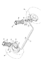
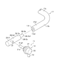
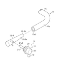
- FIG. 1 is a perspective view illustrating a state in which the stabilizer link 11 is attached to the vehicle.
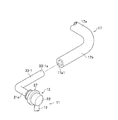
- 2A and 2B are perspective views showing a stabilizer manufacturing method and a stabilizer link joining structure according to the first embodiment of the present invention.
- FIG. 3A is a cross-sectional view of a principal part showing a stabilizer manufacturing method and a stabilizer link joining structure according to the first embodiment of the present invention.
- the suspension device 15 includes a coil spring 15a and a shock absorber 15b.
- the left and right suspension devices 15 are connected via a stabilizer 17 made of a substantially U-shaped spring steel rod or the like.
- the stabilizer 17 is bent from both ends of the torsion bar portion 17a and the torsion bar portion 17a. And a pair of arm portions 17b extending.
- the stabilizer 17 and the shock absorber 15b that supports the wheel W are connected via a stabilizer link 11.
- the connection is the same on the left and right wheels W side.
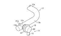
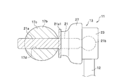
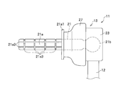
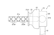
- the stabilizer link 11 is configured by providing ball joints 13 at both ends of a substantially linear support bar 12 made of a metal such as steel.
- the ball joint 13 includes a ball stud 21 made of metal such as steel and a housing 23 made of resin, for example, as shown in FIG. 3A.
- the ball stud 21 has a cylindrical stud portion 21a at one end portion and a spherical ball portion 21b at the other end portion.
- the stud portion 21a and the ball portion 21b are joined by welding.
- the stud portion 21a and the ball portion 21b may be integrally formed.
- the housing 23 is provided at both ends of the support bar 12, and is configured to rotatably support the ball portion 21b of the ball stud 21.
- the resin material of the housing 23 for example, fiber reinforced plastic FRP (Fiber-Reinforced Plastics) or carbon fiber reinforced plastic CFRP (Carbon Fiber-Reinforced Plastics) is preferably used.
- the housing 23 is not limited to resin and may be made of metal.
- the configuration of the pair of ball joints 13 is the same.
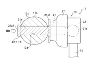
- the stud portion 21a of the ball stud 21 has a flange portion 21a1 as shown in FIG. 3A.
- the flange portion 21a1 will be described in detail later, but caulking portions 22-1 to 2-3 of the stud portion 21a (see Examples 1 to 3 of the second embodiment described later) or welded portions 24-1 to 3 (described later). It has a function of creating a restraining force for the mounting portion 17c acting in the axial direction of the stud portion 21a in cooperation with Examples 1 to 3) of the third embodiment.
- the shape of the flange portion 21a1 is not particularly limited.
- a curved shape along the outer peripheral wall of the mounting portion 17c that can exhibit the above function at a high level may be adopted.
- a circular dust cover 27 made of an elastic body such as rubber is mounted so as to cover these gaps.
- the dust cover 27 plays a role of preventing rainwater, dust and the like from entering the ball joint 13.
- one of the pair of ball joints 13 is fastened and fixed to the bracket 15c of the shock absorber 15b by screw joining. Further, as shown in FIGS. 1, 2A, 2B, and 3A, for example, the other ball joint 13 is manufactured with respect to the mounting portion 17c of the arm portion 17b of the stabilizer 17 according to the embodiment of the present invention. It is joined using the method and the joint structure of the stabilizer link. This will be described in detail below.
- FIGS. 2A, 2B, and 3A A stabilizer manufacturing method and a stabilizer link joining structure according to the first embodiment will be described with reference to FIGS. 2A, 2B, and 3A.
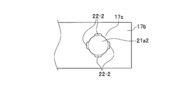
- the mounting portion 17c of the arm portion 17b of the stabilizer 17 has a through-hole (corresponding to the “through-hole” in the present invention) 17d having a shape in which a cylinder just fits.
- the through hole 17d is formed so as to be oriented in a direction perpendicular to the longitudinal direction of the arm portion 17b.
- the stud 21a of the ball stud 21 is inserted through the through hole 17d.
- the outer diameter dimension of the stud portion 21a is substantially equal to or slightly smaller than the inner diameter dimension of the through hole 17d.
- the stabilizer link 11 is joined to the stabilizer 17 by press-fitting the stud portion 21a of the ball stud 21 into the through hole 17d of the mounting portion 17c.
- the frictional force generated between the outer wall surface of the stud portion 21a and the inner wall surface of the through hole 17d is used.
- FIG. 3B is a cross-sectional view of a principal part showing a stabilizer manufacturing method and a stabilizer link joining structure according to the second embodiment of the present invention.
- 4A to 4C are front views respectively showing a stabilizer manufacturing method and a stabilizer link joint structure according to Examples 1 to 3 of the second embodiment of the present invention as viewed from the direction of arrow IIIB shown in FIG. 3B. .
- the through-side end portion 21a2 of the stud portion 21a is inserted in the state where the stud portion 21a of the ball stud 21 is passed through the through-hole 17d of the mounting portion 17c.
- the stabilizer link 11 is joined to the stabilizer 17 by caulking (see FIG. 3B).
- the stud-side end portion 21 a 2 of the stud portion 21 a having a circular shape in front view is point-symmetric.
- the caulking portion 22-1 is formed by caulking these two points.
- the caulking portion 22-1 cooperates with the flange portion 21a1 of the stud portion 21a to restrain the cylindrical mounting portion 17c of the arm portion 17b of the stabilizer 17 in the axial direction of the stud portion 21a. Acts like
- the stud-side end portion 21 a 2 having a circular shape in front view of the stud portion 21 a is point-symmetric.
- the caulking portion 22-2 is formed by caulking these four points.
- the caulking portion 22-2 cooperates with the flange portion 21a1 of the stud portion 21a in the same manner as the caulking portion 22-1 and has a columnar mounting portion 17c included in the arm portion 17b of the stabilizer 17. Is constrained in the axial direction of the stud portion 21a.
- the entire edge of the through-side end portion 21 a 2 having a circular shape when viewed from the front of the stud portion 21 a is formed.
- the caulking portion 22-3 is formed by caulking around the circumference. As shown in FIG. 3B, the caulking portion 22-3 cooperates with the flange portion 21a1 of the stud portion 21a in the same manner as the caulking portions 22-1 and 2-1, and is attached to the columnar shape of the arm portion 17b of the stabilizer 17.
- the portion 17c acts to restrain the stud portion 21a in the axial direction.
- the penetrating side end portion 21a2 of the stud portion 21a is caulked.
- the caulking portions 22-1 to 2-3 are formed by plastic deformation of the penetrating side end portion 21a2.
- the caulking portions 22-1 to 3-3 of the stud portion 21a and the flange portion 21a1 By the cooperation, the binding force acting on the mounting portion 17c acting in the axial direction of the stud portion 21a can realize a firm joint that does not particularly require a measure for joining the stabilizer link 11 to the stabilizer 17.
- FIG. 5A is a cross-sectional view of a principal part showing a stabilizer manufacturing method and a stabilizer link joining structure according to a third embodiment of the present invention.
- FIGS. 5B to 5D are front views respectively showing a stabilizer manufacturing method and a stabilizer link joining structure according to Examples 1 to 3 of the third embodiment of the present invention viewed from the direction of the arrow VA shown in FIG. 5A. .
- the stud portion 21 a has a point-symmetric shape in the through-side end portion 21 a 2 having a circular shape when viewed from the front. These four points are welded to the mounting portion 17c to form a welded portion 24-2. As shown in FIG. 5A, the welded portion 24-2 cooperates with the flange portion 21a1 of the stud portion 21a to cooperate with the flange portion 21a1 of the stud portion 21a, and has a columnar mounting portion 17c that the arm portion 17b of the stabilizer 17 has. Is constrained in the axial direction of the stud portion 21a.
- the entire edge of the through-side end portion 21a2 having a circular shape when viewed from the front of the stud portion 21a is formed.
- the weld 24-3 is formed by welding over the circumference.
- the welded portion 24-3 cooperates with the flange portion 21a1 of the stud portion 21a to restrain the cylindrical mounting portion 17c of the arm portion 17b of the stabilizer 17 in the axial direction of the stud portion 21a. Acts like
- the through-side end portion 21a2 of the stud portion 21a is welded to the mounting portion 17c.
- the welded portions 24-1 to 24-3 are formed.
- the welded portions 24-1 to 3 and the flange portion 21a1 of the stud portion 21a By the cooperation, the binding force acting on the mounting portion 17c acting in the axial direction of the stud portion 21a can realize a firm joint that does not particularly require a measure for joining the stabilizer link 11 to the stabilizer 17.
- FIG. 6 is principal part sectional drawing showing the manufacturing method of the stabilizer which concerns on 4th Embodiment of this invention, and the joining structure of a stabilizer link.
- FIG. 7A and FIG. 7B are explanatory views showing the stud portion 21a of the ball stud 21 used in the stabilizer manufacturing method and the stabilizer link joining structure according to the fourth embodiment of the present invention.
- the stabilizer link 11 is joined to the stabilizer 17 by adhering the outer peripheral wall to the inner peripheral wall of the through hole 17d using an adhesive 26.
- the outer peripheral wall of the stud portion 21a (corresponding to the “adhesive surface of the adhesive” of the present invention). ) are engraved with receiving grooves 21a3 and 21a4 for the adhesive 26, respectively.
- the storage grooves 21a3 and 21a4 of the adhesive 26 serve to store the surplus adhesive 26 and to supply the adhesive 26 to the insufficient part, thereby making the amount of the adhesive 26 uniform on the application surface. .
- FIG. 7A the outer peripheral wall of the stud portion 21a (corresponding to the “adhesive surface of the adhesive” of the present invention). ) are engraved with receiving grooves 21a3 and 21a4 for the adhesive 26, respectively.
- the storage grooves 21a3 and 21a4 of the adhesive 26 serve to store the surplus adhesive 26 and to supply the adhesive 26 to the insufficient part, thereby making the amount of the adhesive 26 uniform on the application surface. .
- the accommodation groove 21a3 of the adhesive 26 is provided so as to extend in the direction along the axial direction of the stud portion 21a and in the direction around the axis of the stud portion 21a.
- the accommodation groove 21a4 of the adhesive 26 is provided so as to extend in the clockwise direction and the counterclockwise direction, respectively, in the spiral direction of the stud portion 21a.
- the stabilizer link 11 is bonded by bonding the outer peripheral wall of the stud portion 21a to the inner peripheral wall of the through hole 17d using the adhesive 26. Since the stabilizer 17 is joined to the stabilizer 17, it is possible to easily realize a firm joint that does not particularly require measures for joining the stabilizer link 11 to the stabilizer 17.
- FIGS. 8A to 8C are perspective views respectively showing a stabilizer manufacturing method and a stabilizer link joining structure according to Examples 1 to 3 of the fifth embodiment of the present invention.
- the stabilizer manufacturing method and the stabilizer link joining structure according to the first to fourth embodiments are used when the stabilizer link 11 is joined to the solid stabilizer 17.
- the stabilizer manufacturing method and the stabilizer link joining structure according to Examples 1 to 3 of the fifth embodiment are similar to the stabilizer link 11 with respect to the hollow tubular stabilizer 17, as shown in FIGS. 8A to 8C. Is different from the stabilizer manufacturing method and the stabilizer link joining structure according to the first to fourth embodiments.
- the arm portion 17b of the stabilizer 17 has on the other hand, substantially cylindrical mounting portions 29-1 to 29-3 are provided separately.
- the substantially cylindrical mounting portion 17 c is formed by the arm portion 17 b in the stabilizer 17. And is provided integrally.
- the material of the attachment portions 29-1 to 29-3 is not particularly limited, and for example, a metal such as iron or a resin (including carbon fiber reinforced plastic) may be appropriately employed.
- the mounting portion 29-1 according to Example 1 of the fifth embodiment is formed in a substantially cylindrical shape.
- a through-hole 31 (corresponding to the “through-hole” of the present invention) 31 having a shape in which a cylinder just fits is provided in the attachment portion 29-1 according to the first embodiment.
- the through hole 31 is formed so as to be oriented in a direction orthogonal to the longitudinal direction of the attachment portion 29-1.
- the stud portion 21 a of the ball stud 21 is inserted into the through hole 31.
- the outer diameter dimension of the stud portion 21 a is substantially equal to or slightly smaller than the inner diameter dimension of the through hole 31.
- the outer diameter dimension of the mounting portion 29-1 according to the first embodiment is substantially equal to or slightly smaller than the inner diameter dimension of the arm portion 17b in the stabilizer 17. Yes.
- the attachment portion 29-1 according to the first embodiment is joined to the arm portion 17b of the stabilizer 17 by press-fitting the outer peripheral wall portion 29-1a of the attachment portion 29-1 into the inner peripheral wall portion 17e1 of the arm portion 17b.
- the inner peripheral wall portion 17e1 of the arm portion 17b and the outer peripheral wall portion 29-1a of the attachment portion 29-1 may be adhesively bonded using an adhesive.
- a configuration in which the arm portion 17b is crimped so as to crush the attachment portion 29-1 in a state where the attachment portion 29-1 is inserted into the hollow space of the arm portion 17b may be employed.
- a portion where the arm portion 17b and the attachment portion 29-1 are adjacent may be welded.
- the mounting portion 29-2 according to Example 2 of the fifth embodiment is formed in a substantially cylindrical shape in appearance as the mounting portion 29-1 according to Example 1.
- the attachment portion 29-2 according to the second embodiment includes a substantially cylindrical large-diameter portion 29-2a and a small-diameter portion 29-2b that are coaxially connected.
- the large diameter portion 29-2a of the mounting portion 29-2 according to the second embodiment has a through hole 31 similar to the mounting portion 29-1 according to the first embodiment. .
- the outer diameter size of the small diameter portion 29-2b of the mounting portion 29-2 according to the second embodiment is substantially equal to the inner diameter size of the arm portion 17b in the stabilizer 17, as shown in FIG. 8B, or , Formed slightly smaller.
- the mounting portion 29-2 according to the second embodiment is configured by pressing the outer peripheral wall portion 29-2b1 of the small-diameter portion 29-2b of the mounting portion 29-2 into the inner peripheral wall portion 17e2 of the arm portion 17b. Is joined to the arm portion 17b.
- the flange portion 29-2c generated by the outer diameter difference between the large diameter portion 29-2a and the small diameter portion 29-2b is abutted against the end surface 17f of the arm portion 17b.
- the outer peripheral wall portion 29-2a1 of the large-diameter portion 29-2a and the outer peripheral wall portion 17b1 of the arm portion 17b of the mounting portion 29-2 are configured to be substantially flush with each other.
- the inner peripheral wall portion 17e2 of the arm portion 17b and the outer peripheral wall portion 29-2b1 of the small diameter portion 29-2b may be adhesively bonded using an adhesive.
- a configuration in which the arm portion 17b is caulked so as to crush the small diameter portion 29-2b in a state where the small diameter portion 29-2b of the attachment portion 29-2 is inserted into the hollow space of the arm portion 17b may be employed.
- a portion where the arm portion 17b and the small diameter portion 29-2b are adjacent may be welded.
- the attachment portion 29-3 according to Example 3 of the fifth embodiment is substantially circular in appearance as the attachment portions 29-1, 2 according to Example 1 or 2. It is formed in a column shape.
- the attachment portion 29-3 according to the third embodiment has a wedge-shaped outer peripheral wall portion 29-3a as shown in FIG. 8C.
- the outer diameter of the tip portion 29-3b facing the inner peripheral wall portion 17e3 of the arm portion 17b in the stabilizer 17 is as shown in FIG. 8C. It is formed smaller than the dimensions.
- the attachment portion 29-3 according to the third embodiment is inserted into the arm portion 17b of the stabilizer 17 by press-fitting the wedge-shaped outer peripheral wall portion 29-3a of the attachment portion 29-3 into the inner peripheral wall portion 17e3 of the arm portion 17b. Be joined.
- the inner peripheral wall portion 17e3 of the arm portion 17b and the wedge-shaped outer peripheral wall portion 29-3a of the attachment portion 29-3 may be adhesively bonded using an adhesive.
- the adjacent portion between the arm portion 17b and the attachment portion 29-3 may be welded. Absent.
- the through holes 31 of the attachment portions 29-1 to 29-3 joined to the arm portion 17b of the stabilizer 17 are provided.
- the stabilizer link 11 is joined to the stabilizer 17 by press-fitting the stud portion 21a of the ball stud 21 (with the stabilizer manufacturing method and the stabilizer link joining structure according to the first embodiment).
- the stud portion 21a of the ball stud 21 is passed through the through holes 31 of the attachment portions 29-1 to 29-3 joined to the arm portion 17b of the stabilizer 17.
- the stabilizer link 11 is joined to the stabilizer 17 by caulking the penetrating end portion 21a2 of the stud portion 21a in the state of being used (using the stabilizer manufacturing method and the stabilizer link joining structure according to the second embodiment). Also good.
- the stud portion 21a of the ball stud 21 is passed through the through holes 31 of the attachment portions 29-1 to 29-3 joined to the arm portion 17b of the stabilizer 17.
- the through-side end 21a2 (see FIG. 5A) of the stud 21a is welded to the mounting portion 17c (the stabilizer manufacturing method and the stabilizer link joining structure according to the third embodiment are used).
- the link 11 may be joined to the stabilizer 17.
- the stud portion 21a of the ball stud 21 is passed through the through holes 31 of the attachment portions 29-1 to 29-3 joined to the arm portion 17b of the stabilizer 17.
- the outer peripheral wall of the stud portion 21a is bonded to the inner peripheral wall of the through-hole 31 using an adhesive (not shown) (using the stabilizer manufacturing method and the stabilizer link connecting structure according to the third embodiment). Accordingly, the stabilizer link 11 may be joined to the stabilizer 17.
- the arm portion 17b of the stabilizer 17 is provided.
- the attachment portions 29-1 to 29-3 separate from the stud portion 21a of the ball stud 21 as an intermediate joining member, it is possible to easily realize a firm joint that does not particularly require a measure for joining the stabilizer link 11 to the stabilizer 17.
- the attachment portions 29 are joined to both ends of the hollow tubular stabilizer 17 so as to close the hollow space, an event that liquid such as water enters the hollow space of the stabilizer 17 is prevented, and generation of rust and the like is prevented. The following effects can also be obtained.
- FIGS. 9A to 9C are perspective views respectively showing a stabilizer manufacturing method and a stabilizer link joint structure according to Examples 1 to 3 of the sixth embodiment of the present invention.
- the stabilizer manufacturing method and the stabilizer link joining structure according to Examples 1 to 3 of the fifth embodiment include the stabilizer link 11 with respect to the hollow tubular stabilizer 17, the arm portion 17 b of the stabilizer 17, and the ball stud 21.
- the stud portion 21a is used for joining via attachment portions 29-1 to 3-3 (see FIGS. 8A to 8C) that are separate from the stud portion 21a.
- the stabilizer manufacturing method and the stabilizer link joining structure according to Examples 1 to 3 of the sixth embodiment are similar to the stabilizer link 11 with respect to the hollow tubular stabilizer 17 as shown in FIGS. 9A to 9C.
- the stud portion 21a of the ball stud 21 is provided.
- substantially cylindrical attachment portions 33-1 to 33-1 extending in a substantially L shape are integrally provided.
- the material of the attachment portions 33-1 to 33-1 is not particularly limited.
- a metal such as iron and a resin (including fiber reinforced plastic and carbon fiber reinforced plastic) may be appropriately employed.
- the outer diameter of the mounting portion 33-1 according to Example 1 of the sixth embodiment is substantially equal to or slightly smaller than the inner diameter of the arm portion 17b in the stabilizer 17. It is formed small.
- the attachment portion 33-1 according to the first embodiment is joined to the arm portion 17b of the stabilizer 17 by press-fitting the outer peripheral wall portion 33-1a of the attachment portion 33-1 into the inner peripheral wall portion 17e1 of the arm portion 17b.
- the inner peripheral wall portion 17e1 of the arm portion 17b and the outer peripheral wall portion 33-1a of the attachment portion 33-1 may be adhesively bonded using an adhesive.
- a configuration in which the arm portion 17b is crimped so as to crush the attachment portion 33-1 in a state where the attachment portion 33-1 is inserted into the hollow space of the arm portion 17b may be employed.
- a portion where the arm portion 17b and the mounting portion 33-1 are adjacent may be welded.
- the mounting portion 33-2 according to Example 2 of the sixth embodiment is formed in a substantially cylindrical shape in appearance as the mounting portion 33-1 according to Example 1. ing.
- the attachment portion 33-2 according to the second embodiment has a substantially cylindrical large-diameter portion 33-2a and a small-diameter portion 33-2b that are coaxially connected.
- the outer diameter size of the small diameter portion 33-2b of the mounting portion 33-2 according to the second embodiment is substantially the same as the inner diameter size of the arm portion 17b in the stabilizer 17, as shown in FIG. 9B, or , Formed slightly smaller.
- the mounting portion 33-2 according to the second embodiment presses the outer peripheral wall portion 33-2b1 of the small-diameter portion 33-2b of the mounting portion 33-2 into the inner peripheral wall portion 17e2 of the arm portion 17b. Is joined to the arm portion 17b.
- the flange portion 33-2c generated by the difference in outer diameter between the large diameter portion 33-2a and the small diameter portion 33-2b is abutted against the end surface 17f of the arm portion 17b.
- the outer peripheral wall portion 33-2a1 of the large-diameter portion 33-2a and the outer peripheral wall 17b1 of the arm portion 17b of the attachment portion 33-2 are configured to be substantially flush with each other.
- the inner peripheral wall portion 17e2 of the arm portion 17b and the outer peripheral wall portion 33-2b1 of the small diameter portion 33-2b may be adhesively bonded using an adhesive. Further, a configuration may be adopted in which the arm portion 17b is crimped so as to crush the small diameter portion 33-2b in a state where the small diameter portion 33-2b of the attachment portion 33-2 is inserted into the hollow space of the arm portion 17b. Further, in a state where the small diameter portion 33-2b of the attachment portion 33-2 is inserted into the hollow space of the arm portion 17b, a portion where the arm portion 17b and the small diameter portion 33-2b are adjacent may be joined by welding.
- the attachment portion 33-3 according to Example 3 of the sixth embodiment is substantially circular in appearance as the attachment portions 33-1 and 3-2 according to Example 1 or 2. It is formed in a column shape.
- the attachment portion 33-3 according to the third embodiment has a wedge-shaped outer peripheral wall portion 33-3a as shown in FIG. 9C.
- the outer diameter of the tip portion 33-3b facing the inner peripheral wall portion 17e3 of the arm portion 17b in the stabilizer 17 is as shown in FIG. 9C. It is formed smaller than the dimensions.
- the mounting portion 33-3 according to the third embodiment is inserted into the arm portion 17b of the stabilizer 17 by press-fitting the wedge-shaped outer peripheral wall portion 33-3a of the mounting portion 33-3 into the inner peripheral wall portion 17e3 of the arm portion 17b. Be joined.
- the inner peripheral wall portion 17e3 of the arm portion 17b and the wedge-shaped outer peripheral wall portion 33-3a of the mounting portion 33-3 may be adhesively bonded using an adhesive. Further, a configuration may be adopted in which the arm portion 17b is crimped so as to crush the attachment portion 33-3 in a state where the wedge-shaped outer peripheral wall portion 33-3a of the attachment portion 33-3 is inserted into the hollow space of the arm portion 17b. Good. Further, with the wedge-shaped outer peripheral wall portion 33-3a of the attachment portion 33-3 inserted into the hollow space of the arm portion 17b, the adjacent portion of the arm portion 17b and the attachment portion 33-3 may be welded. Absent.
- the arm portion 17b of the stabilizer 17 is provided. Is separate from the stud portion 21a of the ball stud 21, but by using the mounting portions 33-1 to 3-3 that are integral with the intermediate joint member as an intermediate joining member, it is not necessary to take any special measures against the stabilizer link 11 from the stabilizer 17. Can be easily realized. Further, since the attachment portions 33-1 to 3-3 are joined to both ends of the hollow tubular stabilizer 17 so as to block the hollow space, it prevents the liquid such as water from entering the hollow space of the stabilizer 17 and generates rust and the like. A secondary effect is also obtained.
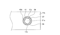
- FIG. 10 is a cross-sectional view of an essential part showing a stabilizer link joint structure according to a seventh embodiment of the present invention.
- FIG. 11 is a front view showing a stabilizer link joint structure according to a seventh embodiment of the present invention as seen from the direction of arrow X shown in FIG.
- a through hole 17d is formed in the mounting portion 17c integral with the arm portion 17b of the stabilizer 17.
- the through hole 17d is formed so as to be oriented in a direction perpendicular to the longitudinal direction of the mounting portion 17c.
- a metal cylindrical member 39 is press-fitted and joined to the through hole 17d (details will be described later).
- the outer diameter dimension of the cylindrical member 39 is substantially equal to or slightly smaller than the inner diameter dimension of the through hole 17d.
- the stud portion 21a of the ball stud 21 is elastically joined to the through hole 17d of the mounting portion 17c with a cylindrical elastic member 37 interposed between the stud portion 21a and the cylindrical member 39 inserted through the through hole 17d of the mounting portion 17c. ing.
- the elastic member 37 has a through hole 38 through which the stud portion 21 a of the ball stud 21 is inserted so as to penetrate the cylindrical shaft center portion.
- the inner diameter dimension of the through hole 38 is substantially equal to or slightly larger than the outer diameter dimension of the stud portion 21a.
- the stud portion 21 a of the ball stud 21 is joined to the inner wall of the through hole 38 opened in the elastic member 37.
- This joining is realized by vulcanizing and bonding the inner wall of the through hole 38 to the stud portion 21 a of the ball stud 21.
- This vulcanization adhesion is performed with an adhesive layer 40a (see FIG. 10) having an appropriate thickness interposed.
- the end face of the elastic member 37 on the side facing the disc-shaped flange portion 21a1 provided on the stud portion 21a is vulcanized and bonded to the flange portion 21a1 to reinforce the above-mentioned joining.
- a configuration may be adopted.
- This vulcanization adhesion is also performed with an adhesive layer 40b (see FIG. 10) having an appropriate thickness interposed.
- a cylindrical member 39 is joined to the outer wall of the elastic member 37 as shown in FIGS.
- This joining is realized by vulcanizing and bonding the outer wall of the elastic member 37 to the inner wall of the cylindrical member 39.
- This vulcanization adhesion is performed with an adhesive layer 41 (see FIG. 10) having an appropriate thickness interposed.
- the elastic member 37 is not particularly limited.
- natural rubber epoxidized natural rubber, isoprene rubber, butadiene rubber, butadiene / isoprene rubber, styrene / butadiene rubber, chloroprene rubber, acrylonitrile / butadiene rubber (NBR), hydrogenated nitrile.
- rubber elastic resin such as rubber, chlorinated polyethylene rubber, butyl rubber, acrylic rubber, ethylene / vinyl acetate / acrylic ester copolymer rubber, silicone rubber, styrene / butadiene rubber.
- the thickness dimension of the elastic member 37 may be set to an appropriate dimension through experiments and simulations in consideration of the frequency of vibration that is desired to prevent transmission between the stabilizer link 11 and the stabilizer 17.
- the cylindrical member 39 is joined to the mounting portion 17c integral with the arm portion 17b of the stabilizer 17 by press-fitting the outer wall of the cylindrical member 39 into the inner wall of the through hole 17d provided in the mounting portion 17c. ing.
- the inner wall of the through hole 17d and the outer wall of the cylindrical member 39 may be adhesively bonded using an adhesive.
- a configuration is adopted in which the stabilizer link 11 is elastically joined to the stabilizer 17 by caulking the through-side end portion of the tubular member 39 in a state where the tubular member 39 is passed through the through hole 17d of the mounting portion 17c. Also good.
- the stabilizer link 11 is elastically joined to the stabilizer 17 by welding the through-side end portion of the tubular member 39 to the attachment portion 17c in a state where the tubular member 39 is passed through the through hole 17d of the attachment portion 17c. May be adopted.
- the stud portion 21a of the ball stud 21 is joined to the through hole 17d with the elastic member 37 interposed between the stud portion 21a and the through hole 17d of the mounting portion 17c.
- the cylindrical member 39 is elastically joined.
- vibration and noise can be suppressed and the riding comfort of the vehicle can be satisfactorily maintained.
- the stabilizer link 11 is joined to the stabilizer 17 by press-fitting the stud portion 21a of the ball stud 21 into the through hole 17d of the mounting portion 17c.
- the stud portion 21a of the ball stud 21 is press-fitted into the through hole 17d of the mounting portion 17c, and the stud portion 21a of the ball stud 21 is passed through the through hole 17d of the mounting portion 17c.
- the stabilizer link 11 is joined to the stabilizer 17 by caulking the through-side end 21a2 of the stud portion 21a.
- the stud portion 21a of the ball stud 21 is press-fitted into the through hole 17d of the mounting portion 17c, and the stud portion 21a of the ball stud 21 is passed through the through hole 17d of the mounting portion 17c.
- the stabilizer link 11 is joined to the stabilizer 17 by adhering the outer peripheral wall of the stud portion 21 a to the inner peripheral wall of the through hole 17 d using the adhesive 26.
- the stud portion 21a of the ball stud 21 is press-fitted into the through hole 17d of the mounting portion 17c, and the stud portion 21a of the ball stud 21 is passed through the through hole 17d of the mounting portion 17c.
- the stabilizer link 11 is joined to the stabilizer 17 by welding the through-side end 21a2 of the stud portion 21a to the attachment portion 17c in the state of being made to be.
- the stabilizer is provided by caulking the through-side end portion 21a2 of the stud portion 21a while the stud portion 21a of the ball stud 21 is passed through the through-hole 17d of the mounting portion 17c.
- the link 11 is joined to the stabilizer 17.
- the restraining force on 17c it is possible to realize a firm joint that does not require any special measures against the separation of the stabilizer link 11 from the stabilizer 17.
- the through-side end portion 21a2 of the stud portion 21a is welded to the mounting portion 17c in a state where the stud portion 21a of the ball stud 21 is passed through the through hole 17d of the mounting portion 17c.
- the stabilizer link 11 is joined to the stabilizer 17.
- the mounting portion acting in the axial direction of the stud portion 21a by the cooperation of the welded portions 24-1 to 3 (see FIG. 5A) and the flange portion 21a1 of the stud portion 21a By virtue of the restraining force on 17c, it is possible to realize a firm joint that does not require any special measures against the separation of the stabilizer link 11 from the stabilizer 17.
- the outer peripheral wall of the stud portion 21a is inserted into the through hole 17d in a state where the stud portion 21a of the ball stud 21 is inserted (including through) into the through hole 17d of the mounting portion 17c.
- the stabilizer link 11 is joined to the stabilizer 17 by adhering to the inner peripheral wall using the adhesive 26.
- the stabilizer link 11 is joined to the stabilizer 17 by bonding the outer peripheral wall of the stud portion 21a to the inner peripheral wall of the through hole 17d using the adhesive 26.
- the adhesive 26 it is possible to easily realize a firm joint that does not particularly require a measure for joining the stabilizer link 11 to the stabilizer 17.
- the outer peripheral wall of the stud portion 21a is bonded to the inner peripheral wall of the through hole 17d using the adhesive 26, and the stud of the ball stud 21 is attached to the through hole 17d of the mounting portion 17c.
- the stabilizer link 11 is joined to the stabilizer 17 by caulking the penetrating side end portion 21a2 of the stud portion 21a with the portion 21a being penetrated.
- the outer peripheral wall of the stud portion 21a is bonded to the inner peripheral wall of the through hole 17d using the adhesive 26, and the stud of the ball stud 21 is attached to the through hole 17d of the mounting portion 17c.
- the stabilizer link 11 is joined to the stabilizer 17 by welding the penetration side end portion 21a2 of the stud portion 21a to the attachment portion 17c in a state where the portion 21a is penetrated.
- the receiving grooves 21a3 and 21a4 (see FIGS. 7A and 7B) of the adhesive 26 are provided on the application surface of the adhesive 26 in contact with the through hole 17d in the stud portion 21a. It has been.
- the attachment portions 29 and 33 are separate members from the stabilizer 17 and are joined to both ends of the stabilizer 17, respectively.
- a stabilizer according to the present invention when the stabilizer link 11 is joined to the hollow tubular stabilizer 17, a firm joint that does not particularly require measures for joining the stabilizer link 11 to the stabilizer 17 is required. It can be easily realized.
- the stud portion 21a of the ball stud 21 is joined to the attaching portion 17c by being press-fitted into the through hole 17d of the attaching portion 17c.
- the stabilizer link 11 is prevented from being joined to the stabilizer 17 by the frictional force generated between the outer wall surface of the stud portion 21a and the inner wall surface of the through hole 17d. It is possible to realize a firm joint that is not particularly required.
- the stud portion 21a of the ball stud 21 is attached by caulking the through-side end portion 21a2 of the stud portion 21a in a state of passing through the through hole 17d of the attachment portion 17c. It is joined to the portion 17c.
- the stud portion 21a is attached in the axial direction by the cooperation of the caulking portions 22-1 to 2-3 (see FIG. 3B) and the flange portion 21a1 of the stud portion 21a.
- the portion 17c By the restraining force with respect to the portion 17c, it is possible to realize a firm joint that does not particularly require measures for the joint link 11 to be separated from the stabilizer 17.
- the stud portion 21a of the ball stud 21 welds the through-side end portion 21a2 of the stud portion 21a to the mounting portion 17c while passing through the through hole 17d of the mounting portion 17c. By doing so, it is joined to the mounting portion 17c.
- the attachment that acts in the axial direction of the stud portion 21a by the cooperation of the welded portions 24-1 to 3 (see FIG. 5A) and the flange portion 21a1 of the stud portion 21a.
- the restraining force with respect to the portion 17c it is possible to realize a firm joint that does not particularly require measures for the joint link 11 to be separated from the stabilizer 17.
- the stud portion 21a of the ball stud 21 is inserted into the through hole 17d of the mounting portion 17c (including the through hole), and the stud portion 21a is bonded to the through hole 17d. It is joined to the attachment part 17c by bonding using
- the stud portion 21a is joined to the mounting portion 17c by bonding the outer peripheral wall of the stud portion 21a to the inner peripheral wall of the through hole 17d using the adhesive 26. Therefore, it is possible to easily realize a firm joint that does not particularly require a measure for joining and separating the stabilizer link 11 with respect to the stabilizer 17.
- the stud portion 21a of the ball stud 21 is joined to the through hole 17d with an elastic member 37 interposed between the stud portion 21a and the through hole 17d of the mounting portion 17c. It is elastically joined to the member 39 (that is, the mounting portion 17c).
- the present invention is limited to this example.
- the cylindrical member 39 may be omitted.
- any configuration may be employed as long as the substantially cylindrical elastic member 37 is interposed between the stud portion 21a of the ball stud 21 and the through hole 17d of the mounting portion 17c. Absent.
Landscapes
- Engineering & Computer Science (AREA)
- Mechanical Engineering (AREA)
- General Engineering & Computer Science (AREA)
- Vehicle Body Suspensions (AREA)
- Pivots And Pivotal Connections (AREA)
Abstract
Description
なお、以下に示す図において、共通の機能を有する部材間、又は、相互に対応する機能を有する部材間には、原則として共通の参照符号を付するものとする。また、説明の便宜のため、部材のサイズおよび形状は、変形または誇張して模式的に表す場合がある。 Hereinafter, a stabilizer manufacturing method and a stabilizer link joining structure according to a plurality of embodiments of the present invention will be described in detail with reference to the drawings as appropriate.
In addition, in the figure shown below, the common referential mark shall be attached | subjected between the members which have a common function, or between the members which have a mutually corresponding function. Further, for convenience of explanation, the size and shape of the member may be schematically represented by being deformed or exaggerated.
はじめに、スタビリンク11及びその周辺の構成について、スタビリンク11を車両(不図示)に取付けた例をあげて説明する。図1は、スタビリンク11の車両への取り付け状態を表す斜視図である。図2A,図2Bは、本発明の第1実施形態に係るスタビライザの製造方法、及びスタビリンクの接合構造を表す斜視図である。図3Aは、本発明の第1実施形態に係るスタビライザの製造方法、及びスタビリンクの接合構造を表す要部断面図である。 <Configuration of
First, the
第1実施形態に係るスタビライザの製造方法、及びスタビリンクの接合構造について、図2A,図2B,図3Aを参照して説明する。
スタビライザ17におけるアーム部17bが有する取付部17cには、図2A,図2B,図3Aに示すように、円柱がちょうど嵌まる形状の貫通孔(本発明の「通孔」に相当する。)17dが開設されている。貫通孔17dは、アーム部17bの長手方向に直交する向きを指向するように形成されている。貫通孔17dには、ボールスタッド21のスタッド部21aが挿通される。スタッド部21aの外径寸法は、貫通孔17dの内径寸法と比べて、実質的に同等、又は、僅かに小さく形成されている。 <Stabilizer manufacturing method and stabilizer link joint structure according to first embodiment>
A stabilizer manufacturing method and a stabilizer link joining structure according to the first embodiment will be described with reference to FIGS. 2A, 2B, and 3A.
As shown in FIGS. 2A, 2B, and 3A, the mounting
第2実施形態に係るスタビライザの製造方法、及びスタビリンクの接合構造について、図3B,図4A~図4Cを参照して説明する。図3Bは、本発明の第2実施形態に係るスタビライザの製造方法、及びスタビリンクの接合構造を表す要部断面図である。図4A~図4Cは、図3Bに示す矢印IIIB方向から視た本発明の第2実施形態の実施例1~3に係るスタビライザの製造方法、及びスタビリンクの接合構造をそれぞれ表す正面図である。 <Stabilizer manufacturing method and stabilizer link joining structure according to second embodiment>
A stabilizer manufacturing method and a stabilizer link joining structure according to the second embodiment will be described with reference to FIGS. 3B and 4A to 4C. FIG. 3B is a cross-sectional view of a principal part showing a stabilizer manufacturing method and a stabilizer link joining structure according to the second embodiment of the present invention. 4A to 4C are front views respectively showing a stabilizer manufacturing method and a stabilizer link joint structure according to Examples 1 to 3 of the second embodiment of the present invention as viewed from the direction of arrow IIIB shown in FIG. 3B. .
第3実施形態に係るスタビライザの製造方法、及びスタビリンクの接合構造について、図5A~図5Dを参照して説明する。図5Aは、本発明の第3実施形態に係るスタビライザの製造方法、及びスタビリンクの接合構造を表す要部断面図である。図5B~図5Dは、図5Aに示す矢印VA方向から視た本発明の第3実施形態の実施例1~3に係るスタビライザの製造方法、及びスタビリンクの接合構造をそれぞれ表す正面図である。 <Stabilizer manufacturing method and stabilizer link joint structure according to third embodiment>
A stabilizer manufacturing method and a stabilizer link joining structure according to the third embodiment will be described with reference to FIGS. 5A to 5D. FIG. 5A is a cross-sectional view of a principal part showing a stabilizer manufacturing method and a stabilizer link joining structure according to a third embodiment of the present invention. FIGS. 5B to 5D are front views respectively showing a stabilizer manufacturing method and a stabilizer link joining structure according to Examples 1 to 3 of the third embodiment of the present invention viewed from the direction of the arrow VA shown in FIG. 5A. .
第4実施形態に係るスタビライザの製造方法、及びスタビリンクの接合構造について、図6、図7A,図7Bを参照して説明する。図6は、本発明の第4実施形態に係るスタビライザの製造方法、及びスタビリンクの接合構造を表す要部断面図である。図7A,図7Bは、本発明の第4実施形態に係るスタビライザの製造方法、及びスタビリンクの接合構造に用いられるボールスタッド21のスタッド部21aを表す説明図である。 <Stabilizer Manufacturing Method and Stabilizing Junction Structure According to Fourth Embodiment>
A stabilizer manufacturing method and a stabilizer link joining structure according to the fourth embodiment will be described with reference to FIGS. 6, 7A and 7B. FIG. 6: is principal part sectional drawing showing the manufacturing method of the stabilizer which concerns on 4th Embodiment of this invention, and the joining structure of a stabilizer link. FIG. 7A and FIG. 7B are explanatory views showing the
第5実施形態の実施例1~3に係るスタビライザの製造方法、及びスタビリンクの接合構造について、図8A~図8Cを参照して説明する。図8A~図8Cは、本発明の第5実施形態の実施例1~3に係るスタビライザの製造方法、及びスタビリンクの接合構造をそれぞれ表す斜視図である。 <Stabilizer Manufacturing Method and Stabilizing Joint Structure According to Examples 1 to 3 of Fifth Embodiment>
A stabilizer manufacturing method and stabilizer link joining structures according to Examples 1 to 3 of the fifth embodiment will be described with reference to FIGS. 8A to 8C. 8A to 8C are perspective views respectively showing a stabilizer manufacturing method and a stabilizer link joining structure according to Examples 1 to 3 of the fifth embodiment of the present invention.
これに対し、第5実施形態の実施例1~3に係るスタビライザの製造方法、及びスタビリンクの接合構造は、図8A~図8Cに示すように、中空管状のスタビライザ17に対してスタビリンク11を接合する点で、第1~第4実施形態に係るスタビライザの製造方法、及びスタビリンクの接合構造と相違している。 The stabilizer manufacturing method and the stabilizer link joining structure according to the first to fourth embodiments are used when the
In contrast, the stabilizer manufacturing method and the stabilizer link joining structure according to Examples 1 to 3 of the fifth embodiment are similar to the
また、中空管状のスタビライザ17の両端に、中空空間を塞ぐように取付部29を接合するため、スタビライザ17の中空空間に水等の液体が浸入する事象を防ぎ、錆等の発生を防ぐという副次的な効果も得られる。 According to the stabilizer manufacturing method and the stabilizer link joining structure according to Examples 1 to 3 of the fifth embodiment, when the
In addition, since the attachment portions 29 are joined to both ends of the hollow
第6実施形態の実施例1~3に係るスタビライザの製造方法、及びスタビリンクの接合構造について、図9A~図9Cを参照して説明する。図9A~図9Cは、本発明の第6実施形態の実施例1~3に係るスタビライザの製造方法、及びスタビリンクの接合構造をそれぞれ表す斜視図である。 <Stabilizer manufacturing method and stabilizer link joint structure according to first to third examples of sixth embodiment>
A stabilizer manufacturing method and a stabilizer link joining structure according to Examples 1 to 3 of the sixth embodiment will be described with reference to FIGS. 9A to 9C. 9A to 9C are perspective views respectively showing a stabilizer manufacturing method and a stabilizer link joint structure according to Examples 1 to 3 of the sixth embodiment of the present invention.
これに対し、第6実施形態の実施例1~3に係るスタビライザの製造方法、及びスタビリンクの接合構造は、図9A~図9Cに示すように、中空管状のスタビライザ17に対してスタビリンク11を、スタビライザ17のアーム部17bとは別体であるが、ボールスタッド21のスタッド部21aと一体の取付部33-1~3(図9A~図9C参照)を介して接合する点で、前記第5実施形態の実施例1~3に係るスタビライザの製造方法、及びスタビリンクの接合構造とは相違している。 The stabilizer manufacturing method and the stabilizer link joining structure according to Examples 1 to 3 of the fifth embodiment include the
On the other hand, the stabilizer manufacturing method and the stabilizer link joining structure according to Examples 1 to 3 of the sixth embodiment are similar to the
また、中空管状のスタビライザ17の両端に、中空空間を塞ぐように取付部33-1~3を接合するため、スタビライザ17の中空空間に水等の液体が浸入する事態を防ぎ、錆等の発生を防ぐという副次的な効果も得られる。 According to the stabilizer manufacturing method and the stabilizer link joining structure according to Examples 1 to 3 of the sixth embodiment, when the
Further, since the attachment portions 33-1 to 3-3 are joined to both ends of the hollow
次に、本発明の第7実施形態に係るスタビリンクの接合構造について、図10,図11を参照して説明する。図10は、本発明の第7実施形態に係るスタビリンクの接合構造を表す要部断面図である。図11は、図10に示す矢印X方向から視た本発明の第7実施形態に係るスタビリンクの接合構造を表す正面図である。 <Joint structure of stabilizer link according to seventh embodiment of the present invention>
Next, a stabilizer link joint structure according to a seventh embodiment of the present invention will be described with reference to FIGS. FIG. 10 is a cross-sectional view of an essential part showing a stabilizer link joint structure according to a seventh embodiment of the present invention. FIG. 11 is a front view showing a stabilizer link joint structure according to a seventh embodiment of the present invention as seen from the direction of arrow X shown in FIG.
筒状部材39の外径寸法は、貫通孔17dの内径寸法と比べて、実質的に同等、又は、僅かに小さく形成されている。ボールスタッド21のスタッド部21aは、取付部17cの貫通孔17dに挿通された筒状部材39との間に円筒形状の弾性部材37を介在させて、取付部17cの貫通孔17dに弾性接合されている。 In the stabilizer link joint structure according to the seventh embodiment of the present invention, as shown in FIGS. 10 and 11, a through
The outer diameter dimension of the
なお、前記圧入に際し、貫通孔17dの内側壁と筒状部材39の外側壁との間を、接着剤を用いて接着接合してもよい。また、取付部17cの貫通孔17dに筒状部材39を貫通させた状態で筒状部材39の貫通側端部をかしめることにより、スタビリンク11をスタビライザ17に弾性接合する構成を採用してもよい。さらに、取付部17cの貫通孔17dに筒状部材39を貫通させた状態で筒状部材39の貫通側端部を取付部17cに溶接することにより、スタビリンク11をスタビライザ17に弾性接合する構成を採用してもよい。 The
In the press-fitting, the inner wall of the through
次に、本発明の複数の実施形態に係るスタビライザの製造方法、及びスタビリンクの接合構造が奏する作用効果について説明する。 [Stabilizer manufacturing method according to a plurality of embodiments of the present invention, and effects obtained by a stabilizer link joining structure]
Next, the method and effect of the stabilizer manufacturing method according to a plurality of embodiments of the present invention and the effect of the stabilizer link joint structure will be described.
以上説明した複数の実施形態は、本発明の具現化の例を示したものである。したがって、これらによって本発明の技術的範囲が限定的に解釈されることがあってはならない。本発明はその要旨又はその主要な特徴から逸脱することなく、様々な形態で実施することができるからである。 [Other Embodiments]
The plurality of embodiments described above show examples of realization of the present invention. Therefore, the technical scope of the present invention should not be limitedly interpreted by these. This is because the present invention can be implemented in various forms without departing from the gist or main features thereof.
12 サポートバー
13 ボールジョイント
17 スタビライザ
17c 取付部
17d 貫通孔(通孔)
21 ボールスタッド
21a スタッド部
21b ボール部
23 ハウジング
26 接着剤
29-1~3 取付部
31 貫通孔(通孔)
33-1~3 取付部
37 弾性部材 11
21
33-1 to 3
Claims (16)
- 車両に備わる懸架装置及びスタビライザを連結するためのスタビリンクを前記スタビライザに接合することにより、スタビリンクが接合されたスタビライザを製造するスタビライザの製造方法であって、
前記スタビリンクは、サポートバーと、当該サポートバーの両端に設けたボールジョイントと、を備え、
前記ボールジョイントは、ボール部及びスタッド部を有するボールスタッドと、当該ボールスタッドの前記ボール部を回動自在に支持するハウジングと、を備え、
前記スタビライザは、金属製の棒状部材により構成され、
前記スタビライザの両端には、前記スタビリンクが接合される取付部がそれぞれ設けられ、
前記取付部には、前記ボールスタッドの前記スタッド部が挿通される通孔がそれぞれ設けられ、
前記取付部の前記通孔に前記ボールスタッドの前記スタッド部を圧入することにより、前記スタビリンクを前記スタビライザに接合する
ことを特徴とするスタビライザの製造方法。 A stabilizer manufacturing method for manufacturing a stabilizer to which a stabilizer link is joined by joining a stabilizer link for connecting a suspension device and a stabilizer provided in a vehicle to the stabilizer.
The stabilizer link includes a support bar and ball joints provided at both ends of the support bar.
The ball joint includes a ball stud having a ball portion and a stud portion, and a housing that rotatably supports the ball portion of the ball stud,
The stabilizer is composed of a metal rod-shaped member,
At both ends of the stabilizer, an attachment portion to which the stabilizer link is joined is provided,
The attachment portion is provided with a through hole through which the stud portion of the ball stud is inserted,
The stabilizer manufacturing method, wherein the stabilizer link is joined to the stabilizer by press-fitting the stud portion of the ball stud into the through hole of the attachment portion. - 請求項1に記載のスタビライザの製造方法であって、
前記取付部の前記通孔に前記ボールスタッドの前記スタッド部を圧入すると共に、当該通孔に当該スタッド部を貫通させた状態で当該スタッド部の貫通側端部をかしめることにより、前記スタビリンクを前記スタビライザに接合する
ことを特徴とするスタビライザの製造方法。 It is a manufacturing method of the stabilizer according to claim 1,
The stabilizer link is formed by press-fitting the stud portion of the ball stud into the through-hole of the mounting portion and caulking the through-side end portion of the stud portion with the stud portion penetrating the through-hole. Is bonded to the stabilizer. A method for manufacturing a stabilizer. - 請求項1に記載のスタビライザの製造方法であって、
前記取付部の前記通孔に前記ボールスタッドの前記スタッド部を圧入すると共に、当該通孔に当該スタッド部を挿通させた状態で当該スタッド部を前記通孔に接着剤を用いて接着することにより、前記スタビリンクを前記スタビライザに接合する
ことを特徴とするスタビライザの製造方法。 It is a manufacturing method of the stabilizer according to claim 1,
The stud portion of the ball stud is press-fitted into the through hole of the mounting portion, and the stud portion is bonded to the through hole with an adhesive in a state where the stud portion is inserted into the through hole. The stabilizer link is joined to the stabilizer. A method of manufacturing a stabilizer, comprising: - 請求項1に記載のスタビライザの製造方法であって、
前記取付部の前記通孔に前記ボールスタッドの前記スタッド部を圧入すると共に、当該通孔に当該スタッド部を貫通させた状態で当該スタッド部の貫通側端部を当該取付部に溶接することにより、前記スタビリンクを前記スタビライザに接合する
ことを特徴とするスタビライザの製造方法。 It is a manufacturing method of the stabilizer according to claim 1,
By press-fitting the stud portion of the ball stud into the through hole of the mounting portion, and welding the through-side end portion of the stud portion to the mounting portion with the stud portion penetrating the through hole. The stabilizer link is joined to the stabilizer. A method of manufacturing a stabilizer, comprising: - 車両に備わる懸架装置及びスタビライザを連結するためのスタビリンクを前記スタビライザに接合することにより、スタビリンクが接合されたスタビライザを製造するスタビライザの製造方法であって、
前記スタビリンクは、サポートバーと、当該サポートバーの両端に設けたボールジョイントと、を備え、
前記ボールジョイントは、ボール部及びスタッド部を有するボールスタッドと、当該ボールスタッドの前記ボール部を回動自在に支持するハウジングと、を備え、
前記スタビライザは、金属製の略円柱状部材により構成され、
前記スタビライザの両端には、前記スタビリンクが接合される取付部がそれぞれ設けられ、
前記取付部には、前記ボールスタッドの前記スタッド部が挿通される通孔がそれぞれ設けられ、
前記取付部の前記通孔に前記ボールスタッドの前記スタッド部を貫通させた状態で当該スタッド部の貫通側端部をかしめることにより、前記スタビリンクを前記スタビライザに接合する
ことを特徴とするスタビライザの製造方法。 A stabilizer manufacturing method for manufacturing a stabilizer to which a stabilizer link is joined by joining a stabilizer link for connecting a suspension device and a stabilizer provided in a vehicle to the stabilizer.
The stabilizer link includes a support bar and ball joints provided at both ends of the support bar.
The ball joint includes a ball stud having a ball portion and a stud portion, and a housing that rotatably supports the ball portion of the ball stud,
The stabilizer is constituted by a substantially cylindrical member made of metal,
At both ends of the stabilizer, an attachment portion to which the stabilizer link is joined is provided,
The attachment portion is provided with a through hole through which the stud portion of the ball stud is inserted,
The stabilizer link is joined to the stabilizer by caulking a penetrating side end portion of the ball stud in a state where the stud portion of the ball stud is passed through the through hole of the mounting portion. Manufacturing method. - 車両に備わる懸架装置及びスタビライザを連結するためのスタビリンクを前記スタビライザに接合することにより、スタビリンクが接合されたスタビライザを製造するスタビライザの製造方法であって、
前記スタビリンクは、サポートバーと、当該サポートバーの両端に設けたボールジョイントと、を備え、
前記ボールジョイントは、ボール部及びスタッド部を有するボールスタッドと、当該ボールスタッドの前記ボール部を回動自在に支持するハウジングと、を備え、
前記スタビライザは、金属製の略円柱状部材により構成され、
前記スタビライザの両端には、前記スタビリンクが接合される取付部がそれぞれ設けられ、
前記取付部には、前記ボールスタッドの前記スタッド部が挿通される通孔がそれぞれ設けられ、
前記取付部の前記通孔に前記ボールスタッドの前記スタッド部を貫通させた状態で当該スタッド部の貫通側端部を当該取付部に溶接することにより、前記スタビリンクを前記スタビライザに接合する
ことを特徴とするスタビライザの製造方法。 A stabilizer manufacturing method for manufacturing a stabilizer to which a stabilizer link is joined by joining a stabilizer link for connecting a suspension device and a stabilizer provided in a vehicle to the stabilizer.
The stabilizer link includes a support bar and ball joints provided at both ends of the support bar.
The ball joint includes a ball stud having a ball portion and a stud portion, and a housing that rotatably supports the ball portion of the ball stud,
The stabilizer is constituted by a substantially cylindrical member made of metal,
At both ends of the stabilizer, an attachment portion to which the stabilizer link is joined is provided,
The attachment portion is provided with a through hole through which the stud portion of the ball stud is inserted,
Joining the stabilizer link to the stabilizer by welding the through-side end portion of the stud portion to the attachment portion in a state where the stud portion of the ball stud is penetrated through the through hole of the attachment portion. A stabilizer manufacturing method characterized. - 車両に備わる懸架装置及びスタビライザを連結するためのスタビリンクを前記スタビライザに接合することにより、スタビリンクが接合されたスタビライザを製造するスタビライザの製造方法であって、
前記スタビリンクは、サポートバーと、当該サポートバーの両端に設けたボールジョイントと、を備え、
前記ボールジョイントは、ボール部及びスタッド部を有するボールスタッドと、当該ボールスタッドの前記ボール部を回動自在に支持するハウジングと、を備え、
前記スタビライザは、金属製の略円柱状部材により構成され、
前記スタビライザの両端には、前記スタビリンクが接合される取付部がそれぞれ設けられ、
前記取付部には、前記ボールスタッドの前記スタッド部が挿通される通孔がそれぞれ設けられ、
前記取付部の前記通孔に前記ボールスタッドの前記スタッド部を挿通させた状態で当該スタッド部を前記通孔に接着剤を用いて接着することにより、前記スタビリンクを前記スタビライザに接合する
ことを特徴とするスタビライザの製造方法。 A stabilizer manufacturing method for manufacturing a stabilizer to which a stabilizer link is joined by joining a stabilizer link for connecting a suspension device and a stabilizer provided in a vehicle to the stabilizer.
The stabilizer link includes a support bar and ball joints provided at both ends of the support bar.
The ball joint includes a ball stud having a ball portion and a stud portion, and a housing that rotatably supports the ball portion of the ball stud,
The stabilizer is constituted by a substantially cylindrical member made of metal,
At both ends of the stabilizer, an attachment portion to which the stabilizer link is joined is provided,
The attachment portion is provided with a through hole through which the stud portion of the ball stud is inserted,
Bonding the stabilizer link to the stabilizer by adhering the stud portion to the through hole with an adhesive in a state where the stud portion of the ball stud is inserted into the through hole of the mounting portion. A stabilizer manufacturing method characterized. - 請求項7に記載のスタビライザの製造方法であって、
前記スタッド部を前記通孔に接着剤を用いて接着すると共に、当該通孔に当該スタッド部を貫通させた状態で当該スタッド部の貫通側端部をかしめることにより、前記スタビリンクを前記スタビライザに接合する
ことを特徴とするスタビライザの製造方法。 It is a manufacturing method of the stabilizer according to claim 7,
The stud portion is bonded to the through hole using an adhesive, and the through end of the stud portion is caulked in a state where the stud portion is passed through the through hole, whereby the stabilizer link is attached to the stabilizer. A method for manufacturing a stabilizer, characterized in that it is bonded to the substrate. - 請求項7に記載のスタビライザの製造方法であって、
前記スタッド部を前記通孔に接着剤を用いて接着すると共に、当該通孔に当該スタッド部を貫通させた状態で当該スタッド部の貫通側端部を当該取付部に溶接することにより、前記スタビリンクを前記スタビライザに接合する
ことを特徴とするスタビライザの製造方法。 It is a manufacturing method of the stabilizer according to claim 7,
The stud portion is bonded to the through-hole using an adhesive, and the stud-side end portion of the stud portion is welded to the attachment portion in a state where the stud portion is penetrated through the through-hole. A method of manufacturing a stabilizer, comprising: joining a link to the stabilizer. - 請求項7に記載のスタビライザの製造方法であって、
前記スタッド部において前記通孔に接する前記接着剤の塗布面には、当該接着剤の収容溝が設けられている
ことを特徴とするスタビライザの製造方法。 It is a manufacturing method of the stabilizer according to claim 7,
A method for manufacturing a stabilizer, wherein an adhesive receiving groove is provided on an application surface of the adhesive in contact with the through hole in the stud portion. - 請求項1~10のいずれか一項に記載のスタビライザの製造方法であって、
前記取付部は、前記スタビライザとは別体の部材であり、当該スタビライザの両端にそれぞれ接合されている
ことを特徴とするスタビライザの製造方法。 A method of manufacturing a stabilizer according to any one of claims 1 to 10,
The mounting portion is a separate member from the stabilizer and is joined to both ends of the stabilizer, respectively. - 車両に備わる懸架装置及びスタビライザを連結するためのスタビリンクを前記スタビライザに接合させるスタビリンクの接合構造であって、
前記スタビリンクは、サポートバーと、当該サポートバーの両端に設けたボールジョイントと、を備え、
前記ボールジョイントは、ボール部及びスタッド部を有するボールスタッドと、当該ボールスタッドの前記ボール部を回動自在に支持するハウジングと、を備え、
前記スタビライザは、金属製の棒状部材により構成され、
前記スタビライザの両端には、前記スタビリンクが接合される取付部がそれぞれ設けられ、
前記取付部には、前記ボールスタッドの前記スタッド部が挿通される通孔がそれぞれ設けられ、
前記ボールスタッドの前記スタッド部は、前記取付部の前記通孔に圧入されることによって当該取付部に接合されている
ことを特徴とするスタビリンクの接合構造。 A stabilizer link joining structure for joining a stabilizer link for connecting a suspension device and a stabilizer provided in a vehicle to the stabilizer,
The stabilizer link includes a support bar and ball joints provided at both ends of the support bar.
The ball joint includes a ball stud having a ball portion and a stud portion, and a housing that rotatably supports the ball portion of the ball stud,
The stabilizer is composed of a metal rod-shaped member,
At both ends of the stabilizer, an attachment portion to which the stabilizer link is joined is provided,
The attachment portion is provided with a through hole through which the stud portion of the ball stud is inserted,
The stud link joining structure, wherein the stud portion of the ball stud is joined to the attachment portion by being press-fitted into the through hole of the attachment portion. - 車両に備わる懸架装置及びスタビライザを連結するためのスタビリンクを前記スタビライザに接合させるスタビリンクの接合構造であって、
前記スタビリンクは、サポートバーと、当該サポートバーの両端に設けたボールジョイントと、を備え、
前記ボールジョイントは、ボール部及びスタッド部を有するボールスタッドと、当該ボールスタッドの前記ボール部を回動自在に支持するハウジングと、を備え、
前記スタビライザは、金属製の棒状部材により構成され、
前記スタビライザの両端には、前記スタビリンクが接合される取付部がそれぞれ設けられ、
前記取付部には、前記ボールスタッドの前記スタッド部が挿通される通孔がそれぞれ設けられ、
前記ボールスタッドの前記スタッド部は、前記取付部の前記通孔を貫通した状態で当該スタッド部の貫通側端部をかしめることによって当該取付部に接合されている
ことを特徴とするスタビリンクの接合構造。 A stabilizer link joining structure for joining a stabilizer link for connecting a suspension device and a stabilizer provided in a vehicle to the stabilizer,
The stabilizer link includes a support bar and ball joints provided at both ends of the support bar.
The ball joint includes a ball stud having a ball portion and a stud portion, and a housing that rotatably supports the ball portion of the ball stud,
The stabilizer is composed of a metal rod-shaped member,
At both ends of the stabilizer, an attachment portion to which the stabilizer link is joined is provided,
The attachment portion is provided with a through hole through which the stud portion of the ball stud is inserted,
The stud portion of the ball stud is joined to the attachment portion by caulking a through-side end portion of the stud portion in a state of passing through the through hole of the attachment portion. Junction structure. - 車両に備わる懸架装置及びスタビライザを連結するためのスタビリンクを前記スタビライザに接合させるスタビリンクの接合構造であって、
前記スタビリンクは、サポートバーと、当該サポートバーの両端に設けたボールジョイントと、を備え、
前記ボールジョイントは、ボール部及びスタッド部を有するボールスタッドと、当該ボールスタッドの前記ボール部を回動自在に支持するハウジングと、を備え、
前記スタビライザは、金属製の棒状部材により構成され、
前記スタビライザの両端には、前記スタビリンクが接合される取付部がそれぞれ設けられ、
前記取付部には、前記ボールスタッドの前記スタッド部が挿通される通孔がそれぞれ設けられ、
前記ボールスタッドの前記スタッド部は、前記取付部の前記通孔を貫通した状態で当該スタッド部の貫通側端部を当該取付部に溶接することによって当該取付部に接合されている
ことを特徴とするスタビリンクの接合構造。 A stabilizer link joining structure for joining a stabilizer link for connecting a suspension device and a stabilizer provided in a vehicle to the stabilizer,
The stabilizer link includes a support bar and ball joints provided at both ends of the support bar.
The ball joint includes a ball stud having a ball portion and a stud portion, and a housing that rotatably supports the ball portion of the ball stud,
The stabilizer is composed of a metal rod-shaped member,
At both ends of the stabilizer, an attachment portion to which the stabilizer link is joined is provided,
The attachment portion is provided with a through hole through which the stud portion of the ball stud is inserted,
The stud portion of the ball stud is joined to the mounting portion by welding a through-side end portion of the stud portion to the mounting portion in a state of passing through the through hole of the mounting portion. Stabilizing joint structure. - 車両に備わる懸架装置及びスタビライザを連結するためのスタビリンクを前記スタビライザに接合させるスタビリンクの接合構造であって、
前記スタビリンクは、サポートバーと、当該サポートバーの両端に設けたボールジョイントと、を備え、
前記ボールジョイントは、ボール部及びスタッド部を有するボールスタッドと、当該ボールスタッドの前記ボール部を回動自在に支持するハウジングと、を備え、
前記スタビライザは、金属製の棒状部材により構成され、
前記スタビライザの両端には、前記スタビリンクが接合される取付部がそれぞれ設けられ、
前記取付部には、前記ボールスタッドの前記スタッド部が挿通される通孔がそれぞれ設けられ、
前記ボールスタッドの前記スタッド部は、前記取付部の前記通孔に挿通した状態で当該スタッド部を当該通孔に接着剤を用いて接着することによって当該取付部に接合されている
ことを特徴とするスタビリンクの接合構造。 A stabilizer link joining structure for joining a stabilizer link for connecting a suspension device and a stabilizer provided in a vehicle to the stabilizer,
The stabilizer link includes a support bar and ball joints provided at both ends of the support bar.
The ball joint includes a ball stud having a ball portion and a stud portion, and a housing that rotatably supports the ball portion of the ball stud,
The stabilizer is composed of a metal rod-shaped member,
At both ends of the stabilizer, an attachment portion to which the stabilizer link is joined is provided,
The attachment portion is provided with a through hole through which the stud portion of the ball stud is inserted,
The stud portion of the ball stud is joined to the mounting portion by bonding the stud portion to the through hole using an adhesive in a state of being inserted into the through hole of the mounting portion. Stabilizing joint structure. - 車両に備わる懸架装置及びスタビライザを連結するためのスタビリンクを前記スタビライザに接合させるスタビリンクの接合構造であって、
前記スタビリンクは、サポートバーと、当該サポートバーの両端に設けたボールジョイントと、を備え、
前記ボールジョイントは、ボール部及びスタッド部を有するボールスタッドと、当該ボールスタッドの前記ボール部を回動自在に支持するハウジングと、を備え、
前記スタビライザは、金属製の棒状部材により構成され、
前記スタビライザの両端には、前記スタビリンクが接合される取付部がそれぞれ設けられ、
前記取付部には、前記ボールスタッドの前記スタッド部が挿通される通孔がそれぞれ設けられ、
前記ボールスタッドの前記スタッド部は、前記取付部の前記通孔との間に弾性部材を介在させて当該取付部に接合されている
ことを特徴とするスタビリンクの接合構造。 A stabilizer link joining structure for joining a stabilizer link for connecting a suspension device and a stabilizer provided in a vehicle to the stabilizer,
The stabilizer link includes a support bar and ball joints provided at both ends of the support bar.
The ball joint includes a ball stud having a ball portion and a stud portion, and a housing that rotatably supports the ball portion of the ball stud,
The stabilizer is composed of a metal rod-shaped member,
At both ends of the stabilizer, an attachment portion to which the stabilizer link is joined is provided,
The attachment portion is provided with a through hole through which the stud portion of the ball stud is inserted,
The stud link joining structure, wherein the stud portion of the ball stud is joined to the attachment portion with an elastic member interposed between the stud portion and the through hole of the attachment portion.
Priority Applications (8)
| Application Number | Priority Date | Filing Date | Title |
|---|---|---|---|
| JP2018537183A JPWO2018043248A1 (en) | 2016-09-05 | 2017-08-23 | Method of manufacturing stabilizer, and joint structure of stabilizer link |
| EP17846253.7A EP3508362A4 (en) | 2016-09-05 | 2017-08-23 | Stabilizer manufacturing method, and joint structure for stabilizer link |
| BR112019002658A BR112019002658A2 (en) | 2016-09-05 | 2017-08-23 | Stabilizer manufacturing method and bevel joint structure |
| CN201780052468.7A CN109641502A (en) | 2016-09-05 | 2017-08-23 | The manufacturing method of stabilizer and the joint construction of stabilizer connecting rod |
| CA3035885A CA3035885A1 (en) | 2016-09-05 | 2017-08-23 | Stabilizer manufacturing method, and joint structure for stabilizer link |
| KR1020197007498A KR20190038916A (en) | 2016-09-05 | 2017-08-23 | METHOD FOR MANUFACTURING STABILIZER AND JOINT STRUCTURE OF STABILIZER LINK |
| US16/330,590 US20210276390A1 (en) | 2016-09-05 | 2017-08-23 | Stabilizer manufacturing method, and joint structure for stabilizer link |
| MX2019002539A MX2019002539A (en) | 2016-09-05 | 2017-08-23 | Stabilizer manufacturing method, and joint structure for stabilizer link. |
Applications Claiming Priority (4)
| Application Number | Priority Date | Filing Date | Title |
|---|---|---|---|
| JP2016172572 | 2016-09-05 | ||
| JP2016-172572 | 2016-09-05 | ||
| JP2017-109235 | 2017-06-01 | ||
| JP2017109235 | 2017-06-01 |
Publications (1)
| Publication Number | Publication Date |
|---|---|
| WO2018043248A1 true WO2018043248A1 (en) | 2018-03-08 |
Family
ID=61300693
Family Applications (1)
| Application Number | Title | Priority Date | Filing Date |
|---|---|---|---|
| PCT/JP2017/030140 WO2018043248A1 (en) | 2016-09-05 | 2017-08-23 | Stabilizer manufacturing method, and joint structure for stabilizer link |
Country Status (9)
| Country | Link |
|---|---|
| US (1) | US20210276390A1 (en) |
| EP (1) | EP3508362A4 (en) |
| JP (1) | JPWO2018043248A1 (en) |
| KR (1) | KR20190038916A (en) |
| CN (1) | CN109641502A (en) |
| BR (1) | BR112019002658A2 (en) |
| CA (1) | CA3035885A1 (en) |
| MX (1) | MX2019002539A (en) |
| WO (1) | WO2018043248A1 (en) |
Cited By (3)
| Publication number | Priority date | Publication date | Assignee | Title |
|---|---|---|---|---|
| KR102344702B1 (en) * | 2021-07-05 | 2021-12-30 | 김원홍 | Inner tube manufacturing process that is mounted on the suspension for passenger cars |
| US11376919B2 (en) * | 2020-05-06 | 2022-07-05 | Zf Friedrichshafen Ag | Chassis component and stabilizer arrangement for a chassis of a vehicle with such a chassis component |
| US20220363103A1 (en) * | 2019-07-02 | 2022-11-17 | Nhk Spring Co., Ltd. | Stabilizer |
Citations (11)
| Publication number | Priority date | Publication date | Assignee | Title |
|---|---|---|---|---|
| JPS49121668U (en) * | 1973-02-14 | 1974-10-18 | ||
| JPH0652857U (en) * | 1992-12-28 | 1994-07-19 | ヤマハ株式会社 | Golf club |
| JP2000320529A (en) * | 1999-05-13 | 2000-11-24 | Tokai Rubber Ind Ltd | Propeller shaft |
| JP2001055035A (en) * | 1999-07-01 | 2001-02-27 | American Accel & Manufacturing Inc | Plug-in direct acting stabilizer bar link |
| JP2002227828A (en) * | 2001-02-02 | 2002-08-14 | Honda Motor Co Ltd | Connecting method for ball stud and lever member |
| JP2002256828A (en) * | 2001-03-05 | 2002-09-11 | Mitsubishi Electric Corp | Valve timing adjusting device |
| JP2002333010A (en) * | 2001-05-08 | 2002-11-22 | Nissan Motor Co Ltd | Attaching structure for ball joint |
| JP2007192326A (en) * | 2006-01-19 | 2007-08-02 | Gkn ドライブライン トルクテクノロジー株式会社 | Motive power transmission device |
| JP2009031745A (en) * | 2007-07-04 | 2009-02-12 | 21:Kk | Rimless glasses |
| JP2015151097A (en) * | 2014-02-18 | 2015-08-24 | 日本発條株式会社 | Link arm member and manufacturing method of the same |
| JP2016084057A (en) | 2014-10-28 | 2016-05-19 | 日本発條株式会社 | Link arm member |
Family Cites Families (10)
| Publication number | Priority date | Publication date | Assignee | Title |
|---|---|---|---|---|
| US3679248A (en) * | 1971-08-05 | 1972-07-25 | Trw Inc | Ball joint |
| JPH0542049U (en) * | 1991-11-12 | 1993-06-08 | 株式会社リズム | Tyrod |
| US6076840A (en) * | 1998-05-19 | 2000-06-20 | American Axle & Manufacturing, Inc. | Self-locking plug-in stabilizer bar links |
| KR20030082271A (en) * | 2002-04-17 | 2003-10-22 | 기아자동차주식회사 | Coupling Structure Of Pitman Arm |
| JP2004251410A (en) * | 2003-02-21 | 2004-09-09 | Nippon Thompson Co Ltd | Shaft coupling |
| KR20080109972A (en) * | 2007-06-14 | 2008-12-18 | 현대자동차주식회사 | A stabilizer of an automobile |
| KR20130056642A (en) * | 2011-11-22 | 2013-05-30 | 현대자동차주식회사 | Displacement adjusting apparatus of stabilizer-bar link |
| JP5476402B2 (en) * | 2012-02-16 | 2014-04-23 | 日本発條株式会社 | Stabilink and manufacturing method thereof |
| DE102014110139A1 (en) * | 2014-05-27 | 2015-12-03 | Heiko Schmidt | A method for producing a riveted joint between a ball joint pin and a sheet-metal component and associated prefabricated assembly |
| CN204383117U (en) * | 2014-11-25 | 2015-06-10 | 广汽吉奥汽车有限公司 | A kind of multipurpose automobile and Panhard rod pipe link assembly thereof |
-
2017
- 2017-08-23 EP EP17846253.7A patent/EP3508362A4/en not_active Withdrawn
- 2017-08-23 CN CN201780052468.7A patent/CN109641502A/en active Pending
- 2017-08-23 MX MX2019002539A patent/MX2019002539A/en unknown
- 2017-08-23 KR KR1020197007498A patent/KR20190038916A/en active IP Right Grant
- 2017-08-23 US US16/330,590 patent/US20210276390A1/en not_active Abandoned
- 2017-08-23 WO PCT/JP2017/030140 patent/WO2018043248A1/en unknown
- 2017-08-23 CA CA3035885A patent/CA3035885A1/en not_active Abandoned
- 2017-08-23 BR BR112019002658A patent/BR112019002658A2/en not_active Application Discontinuation
- 2017-08-23 JP JP2018537183A patent/JPWO2018043248A1/en active Pending
Patent Citations (11)
| Publication number | Priority date | Publication date | Assignee | Title |
|---|---|---|---|---|
| JPS49121668U (en) * | 1973-02-14 | 1974-10-18 | ||
| JPH0652857U (en) * | 1992-12-28 | 1994-07-19 | ヤマハ株式会社 | Golf club |
| JP2000320529A (en) * | 1999-05-13 | 2000-11-24 | Tokai Rubber Ind Ltd | Propeller shaft |
| JP2001055035A (en) * | 1999-07-01 | 2001-02-27 | American Accel & Manufacturing Inc | Plug-in direct acting stabilizer bar link |
| JP2002227828A (en) * | 2001-02-02 | 2002-08-14 | Honda Motor Co Ltd | Connecting method for ball stud and lever member |
| JP2002256828A (en) * | 2001-03-05 | 2002-09-11 | Mitsubishi Electric Corp | Valve timing adjusting device |
| JP2002333010A (en) * | 2001-05-08 | 2002-11-22 | Nissan Motor Co Ltd | Attaching structure for ball joint |
| JP2007192326A (en) * | 2006-01-19 | 2007-08-02 | Gkn ドライブライン トルクテクノロジー株式会社 | Motive power transmission device |
| JP2009031745A (en) * | 2007-07-04 | 2009-02-12 | 21:Kk | Rimless glasses |
| JP2015151097A (en) * | 2014-02-18 | 2015-08-24 | 日本発條株式会社 | Link arm member and manufacturing method of the same |
| JP2016084057A (en) | 2014-10-28 | 2016-05-19 | 日本発條株式会社 | Link arm member |
Non-Patent Citations (1)
| Title |
|---|
| See also references of EP3508362A4 |
Cited By (4)
| Publication number | Priority date | Publication date | Assignee | Title |
|---|---|---|---|---|
| US20220363103A1 (en) * | 2019-07-02 | 2022-11-17 | Nhk Spring Co., Ltd. | Stabilizer |
| US11820192B2 (en) * | 2019-07-02 | 2023-11-21 | Nhk Spring Co., Ltd. | Stabilizer |
| US11376919B2 (en) * | 2020-05-06 | 2022-07-05 | Zf Friedrichshafen Ag | Chassis component and stabilizer arrangement for a chassis of a vehicle with such a chassis component |
| KR102344702B1 (en) * | 2021-07-05 | 2021-12-30 | 김원홍 | Inner tube manufacturing process that is mounted on the suspension for passenger cars |
Also Published As
| Publication number | Publication date |
|---|---|
| EP3508362A4 (en) | 2020-05-06 |
| KR20190038916A (en) | 2019-04-09 |
| BR112019002658A2 (en) | 2019-05-28 |
| US20210276390A1 (en) | 2021-09-09 |
| EP3508362A1 (en) | 2019-07-10 |
| CA3035885A1 (en) | 2018-03-08 |
| MX2019002539A (en) | 2019-07-15 |
| JPWO2018043248A1 (en) | 2019-06-24 |
| CN109641502A (en) | 2019-04-16 |
Similar Documents
| Publication | Publication Date | Title |
|---|---|---|
| WO2018043248A1 (en) | Stabilizer manufacturing method, and joint structure for stabilizer link | |
| JP6909815B2 (en) | Vehicle skeleton support device | |
| US8152186B2 (en) | Suspension arm | |
| JP2011116336A (en) | Suspension arm | |
| JP6431380B2 (en) | Vibration isolator | |
| KR20210010205A (en) | Bush With Improved Tuning Freedom and Suspension System Thereby | |
| US20170203629A1 (en) | Twist Beam Axle Assembly And Method Of Manufacturing Same | |
| WO2016136916A1 (en) | Bracket for vibration-damping device, bracket-equipped vibration-damping device, and method for manufacturing bracket for vibration-damping device | |
| JP2018090245A (en) | Stabilizer for suspension of vehicle | |
| KR101450319B1 (en) | Mounting Bush of Gear Housing for Steering Apparatus | |
| CN110709264B (en) | Joint structure of stabilizer link | |
| JP6680184B2 (en) | Vehicle member mounting structure | |
| JP5119863B2 (en) | Pillow ball structure and suspension structure | |
| JP2008106867A (en) | Strut mount | |
| JP5193002B2 (en) | Suspension arm fastening structure | |
| JP2013224106A (en) | Steering device | |
| KR101450323B1 (en) | Mounting Bush of Gear Housing for Steering Apparatus | |
| US20180003261A1 (en) | Shock absorber | |
| KR102552072B1 (en) | Inside Fixing type Mounting Bush Unit and Sub Frame thereby | |
| JP2009149166A (en) | Steering device | |
| KR102474602B1 (en) | Rigid Pressing type Insulator and Suspension System thereby | |
| KR101427455B1 (en) | Rack Bar Supporting Device of Steering Apparatus for Vehicle and Steering Apparatus for Vehicle having The Same | |
| JP2016161102A (en) | Strut type suspension device | |
| JP2016175535A (en) | Steering device | |
| WO2016113793A1 (en) | Anti-vibration device |
Legal Events
| Date | Code | Title | Description |
|---|---|---|---|
| 121 | Ep: the epo has been informed by wipo that ep was designated in this application |
Ref document number: 17846253 Country of ref document: EP Kind code of ref document: A1 |
|
| ENP | Entry into the national phase |
Ref document number: 2018537183 Country of ref document: JP Kind code of ref document: A |
|
| ENP | Entry into the national phase |
Ref document number: 3035885 Country of ref document: CA |
|
| NENP | Non-entry into the national phase |
Ref country code: DE |
|
| ENP | Entry into the national phase |
Ref document number: 20197007498 Country of ref document: KR Kind code of ref document: A |
|
| REG | Reference to national code |
Ref country code: BR Ref legal event code: B01A Ref document number: 112019002658 Country of ref document: BR |
|
| ENP | Entry into the national phase |
Ref document number: 2017846253 Country of ref document: EP Effective date: 20190405 |
|
| ENP | Entry into the national phase |
Ref document number: 112019002658 Country of ref document: BR Kind code of ref document: A2 Effective date: 20190208 |