WO2018042983A1 - データ作成装置、光制御装置、データ作成方法、及びデータ作成プログラム - Google Patents
データ作成装置、光制御装置、データ作成方法、及びデータ作成プログラム Download PDFInfo
- Publication number
- WO2018042983A1 WO2018042983A1 PCT/JP2017/027501 JP2017027501W WO2018042983A1 WO 2018042983 A1 WO2018042983 A1 WO 2018042983A1 JP 2017027501 W JP2017027501 W JP 2017027501W WO 2018042983 A1 WO2018042983 A1 WO 2018042983A1
- Authority
- WO
- WIPO (PCT)
- Prior art keywords
- function
- waveform
- intensity
- spectrum
- waveform function
- Prior art date
- Legal status (The legal status is an assumption and is not a legal conclusion. Google has not performed a legal analysis and makes no representation as to the accuracy of the status listed.)
- Ceased
Links
Images






Classifications
-
- G—PHYSICS
- G02—OPTICS
- G02F—OPTICAL DEVICES OR ARRANGEMENTS FOR THE CONTROL OF LIGHT BY MODIFICATION OF THE OPTICAL PROPERTIES OF THE MEDIA OF THE ELEMENTS INVOLVED THEREIN; NON-LINEAR OPTICS; FREQUENCY-CHANGING OF LIGHT; OPTICAL LOGIC ELEMENTS; OPTICAL ANALOGUE/DIGITAL CONVERTERS
- G02F2/00—Demodulating light; Transferring the modulation of modulated light; Frequency-changing of light
- G02F2/004—Transferring the modulation of modulated light, i.e. transferring the information from one optical carrier of a first wavelength to a second optical carrier of a second wavelength, e.g. all-optical wavelength converter
-
- G—PHYSICS
- G02—OPTICS
- G02F—OPTICAL DEVICES OR ARRANGEMENTS FOR THE CONTROL OF LIGHT BY MODIFICATION OF THE OPTICAL PROPERTIES OF THE MEDIA OF THE ELEMENTS INVOLVED THEREIN; NON-LINEAR OPTICS; FREQUENCY-CHANGING OF LIGHT; OPTICAL LOGIC ELEMENTS; OPTICAL ANALOGUE/DIGITAL CONVERTERS
- G02F1/00—Devices or arrangements for the control of the intensity, colour, phase, polarisation or direction of light arriving from an independent light source, e.g. switching, gating or modulating; Non-linear optics
- G02F1/01—Devices or arrangements for the control of the intensity, colour, phase, polarisation or direction of light arriving from an independent light source, e.g. switching, gating or modulating; Non-linear optics for the control of the intensity, phase, polarisation or colour
-
- H—ELECTRICITY
- H01—ELECTRIC ELEMENTS
- H01S—DEVICES USING THE PROCESS OF LIGHT AMPLIFICATION BY STIMULATED EMISSION OF RADIATION [LASER] TO AMPLIFY OR GENERATE LIGHT; DEVICES USING STIMULATED EMISSION OF ELECTROMAGNETIC RADIATION IN WAVE RANGES OTHER THAN OPTICAL
- H01S3/00—Lasers, i.e. devices using stimulated emission of electromagnetic radiation in the infrared, visible or ultraviolet wave range
- H01S3/005—Optical devices external to the laser cavity, specially adapted for lasers, e.g. for homogenisation of the beam or for manipulating laser pulses, e.g. pulse shaping
- H01S3/0057—Temporal shaping, e.g. pulse compression, frequency chirping
-
- G—PHYSICS
- G02—OPTICS
- G02F—OPTICAL DEVICES OR ARRANGEMENTS FOR THE CONTROL OF LIGHT BY MODIFICATION OF THE OPTICAL PROPERTIES OF THE MEDIA OF THE ELEMENTS INVOLVED THEREIN; NON-LINEAR OPTICS; FREQUENCY-CHANGING OF LIGHT; OPTICAL LOGIC ELEMENTS; OPTICAL ANALOGUE/DIGITAL CONVERTERS
- G02F2201/00—Constructional arrangements not provided for in groups G02F1/00 - G02F7/00
- G02F2201/30—Constructional arrangements not provided for in groups G02F1/00 - G02F7/00 grating
- G02F2201/305—Constructional arrangements not provided for in groups G02F1/00 - G02F7/00 grating diffraction grating
-
- G—PHYSICS
- G02—OPTICS
- G02F—OPTICAL DEVICES OR ARRANGEMENTS FOR THE CONTROL OF LIGHT BY MODIFICATION OF THE OPTICAL PROPERTIES OF THE MEDIA OF THE ELEMENTS INVOLVED THEREIN; NON-LINEAR OPTICS; FREQUENCY-CHANGING OF LIGHT; OPTICAL LOGIC ELEMENTS; OPTICAL ANALOGUE/DIGITAL CONVERTERS
- G02F2203/00—Function characteristic
- G02F2203/26—Pulse shaping; Apparatus or methods therefor
-
- H—ELECTRICITY
- H01—ELECTRIC ELEMENTS
- H01S—DEVICES USING THE PROCESS OF LIGHT AMPLIFICATION BY STIMULATED EMISSION OF RADIATION [LASER] TO AMPLIFY OR GENERATE LIGHT; DEVICES USING STIMULATED EMISSION OF ELECTROMAGNETIC RADIATION IN WAVE RANGES OTHER THAN OPTICAL
- H01S3/00—Lasers, i.e. devices using stimulated emission of electromagnetic radiation in the infrared, visible or ultraviolet wave range
- H01S3/005—Optical devices external to the laser cavity, specially adapted for lasers, e.g. for homogenisation of the beam or for manipulating laser pulses, e.g. pulse shaping
- H01S3/0085—Modulating the output, i.e. the laser beam is modulated outside the laser cavity
Definitions
- the present disclosure relates to a data creation device, a light control device, a data creation method, and a data creation program.
- Non-Patent Document 1 discloses a technique for shaping an optical pulse by modulating a phase spectrum using a spatial light modulator (SLM).
- SLM spatial light modulator
- a phase spectrum for obtaining a desired optical pulse waveform is calculated using an iterative Fourier method.
- phase spectrum and intensity spectrum of an optical pulse with an SLM as a technique for controlling the time waveform of various lights such as ultrashort pulse light.
- a phase spectrum and an intensity spectrum for bringing the temporal intensity waveform of light closer to a desired waveform are calculated, and a modulation pattern for giving the phase spectrum and the intensity spectrum to light is presented to the SLM.
- the wavelength component (frequency component) of light constituting the time intensity waveform cannot be controlled.
- the wavelength when generating output light including a plurality of pulses, if the wavelength can be varied for each of the plurality of pulses, it can be applied to various apparatuses such as a laser processing apparatus, an ultrahigh-speed imaging camera, and a terahertz wave generation apparatus. Become.
- Embodiments are intended to provide a data creation device, a light control device, a data creation method, and a data creation program capable of controlling the wavelength component (frequency component) of light constituting a time intensity waveform.
- the embodiment of the present invention is a data creation device.
- the data creation device is a device that creates data for controlling the spatial light modulator, performs a Fourier transform on the first waveform function in the frequency domain including the intensity spectrum function and the phase spectrum function, A Fourier transform unit that generates a second waveform function in a time domain including a time phase waveform function, a function replacement unit that replaces the second waveform function with a time intensity waveform function based on a desired waveform, a desired waveform, and A waveform function correction unit for correcting the second waveform function so that the spectrogram of the second waveform function approaches a target spectrogram generated in advance according to a desired wavelength band, and inverse Fourier transform is performed on the corrected second waveform function.
- An inverse Fourier transform unit for generating a third waveform function in the frequency domain, and an intensity spectrum function or a phase spectrum function of the third waveform function.
- a data generation unit for generating data Zui.
- the embodiment of the present invention is a data creation method.
- the data creation method is a method of creating data for controlling the spatial light modulator, performing Fourier transform on the first waveform function in the frequency domain including the intensity spectrum function and the phase spectrum function, A Fourier transform step for generating a second waveform function in the time domain including a time phase waveform function, a function replacement step for replacing the second waveform function with a time intensity waveform function based on a desired waveform, a desired waveform, and A waveform function correcting step for correcting the second waveform function so that the spectrogram of the second waveform function approaches a target spectrogram generated in advance according to a desired wavelength band, and an inverse Fourier transform is performed on the corrected second waveform function.
- An inverse Fourier transform step for generating a third waveform function in the frequency domain, and an intensity spectrum function of the third waveform function Includes a data generating step of generating data based on the phase spectrum function.
- the embodiment of the present invention is a data creation program.
- the data creation program is a program for creating data for controlling the spatial light modulator, which performs Fourier transform on the first waveform function in the frequency domain including the intensity spectrum function and the phase spectrum function, A Fourier transform step for generating a second waveform function in the time domain including a time phase waveform function, a function replacement step for replacing the second waveform function with a time intensity waveform function based on a desired waveform, a desired waveform, and A waveform function correcting step for correcting the second waveform function so that the spectrogram of the second waveform function approaches a target spectrogram generated in advance according to a desired wavelength band, and an inverse Fourier transform is performed on the corrected second waveform function.
- An inverse Fourier transform step for generating a third waveform function in the frequency domain, and an intensity step of the third waveform function. Based on the vector function or phase spectral function to execute a data generating step of generating data, to the computer.
- the second waveform function in the time domain is generated by performing Fourier transform on the first waveform function in the frequency domain, and then the desired waveform is obtained with respect to the second waveform function. Replaces the time-intensity waveform function based on it. After the replacement of the time intensity waveform function, the second waveform function is modified so that the spectrogram of the second waveform function approaches the target spectrogram before the inverse Fourier transform.
- This target spectrogram is generated in advance according to a desired waveform and a desired wavelength band, and by this processing, the wavelength band of the second waveform function is corrected to the desired wavelength band. Therefore, the third waveform function obtained by inverse Fourier transform of the second waveform function is also a function within a desired wavelength band. Data for controlling the spatial light modulator is generated based on the intensity spectrum function or the phase spectrum function of the third waveform function. As mentioned above, according to said apparatus, method, and program, it becomes possible to control the wavelength component (frequency component) of the light which comprises a time intensity waveform.
- the light control device is a spatial light modulator that modulates at least one of a light source that outputs input light, a spectroscopic element that divides the input light, and an intensity spectrum or phase spectrum of the input light after the spectrum and outputs modulated light. And an optical system that collects the modulated light, and the spatial light modulator generates at least one of the intensity spectrum and the phase spectrum of the input light based on the data created by the data creation device configured as described above. Modulate.
- the wavelength component (frequency component) of the light constituting the time intensity waveform is controlled by controlling the spatial light modulator based on the data created by the data creation device having the above configuration. Is possible.
- the light control device the data creation method, and the data creation program according to the embodiment, it is possible to control the wavelength component (frequency component) of light constituting the time intensity waveform.
- FIG. 1 is a diagram schematically illustrating a configuration of a light control device according to an embodiment.
- FIG. 2 is a diagram illustrating a configuration of an optical system included in the light control device.
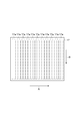
- FIG. 3 is a diagram illustrating a modulation surface of the SLM.
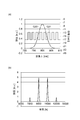
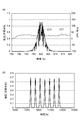
- FIGS. 4A and 4B are diagrams showing (a) the spectrum waveform of the input light in the form of a single pulse, and (b) the time intensity waveform of the input light.
- 5A is a diagram showing a spectrum waveform of output light when rectangular wave-like phase spectrum modulation is applied in the SLM
- FIG. 5B is a diagram showing a time intensity waveform of output light.
- FIG. 6 is a block diagram showing the internal configuration of the phase spectrum design unit and the intensity spectrum design unit.
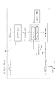
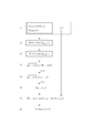
- FIG. 7 is a diagram showing a calculation procedure of the phase spectrum by the iterative Fourier transform method.
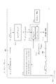
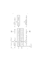
- FIG. 8 is a diagram showing a calculation procedure of the spectrum phase in the phase spectrum design unit.
- FIG. 9 is a diagram showing a calculation procedure of the spectrum intensity in the intensity spectrum design unit.
- FIG. 10 is a diagram illustrating an example of a target spectrogram generation procedure in the target generation unit.
- FIG. 11 is a diagram illustrating an example of a procedure for calculating an intensity spectrum.
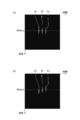
- FIGS. 12A and 12B are diagrams showing a process for creating a target spectrogram.
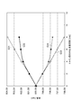
- FIG. 13 is a graph showing the center wavelengths of two domains included in each spectrogram whose evaluation value satisfies a predetermined condition for each corresponding target spectrogram, and the center wavelength interval between the domains.
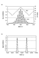
- FIG. 14 shows (a) a graph showing a spectrum waveform when the combination of center wavelengths of two domains of a target spectrogram is (800 nm, 800 nm), and (b) a Fourier transform of the spectrum waveform of (a). It is a graph which shows the time intensity waveform of the produced output light.
- FIG. 14 shows (a) a graph showing a spectrum waveform when the combination of center wavelengths of two domains of a target spectrogram is (800 nm, 800 nm), and (b) a Fourier transform of the spectrum waveform of (a). It is a graph which shows the time intensity waveform of the produced output light.
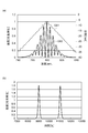
- FIG. 15 shows (a) a graph showing a spectrum waveform when the combination of center wavelengths of two domains of a target spectrogram is (802 nm, 798 nm), and (b) a Fourier transform of the spectrum waveform of (a). It is a graph which shows the time intensity waveform of the produced output light.
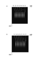
- FIG. 16A is a diagram showing a target spectrogram used in the second embodiment
- FIG. 16B is a spectrogram calculated based on the target spectrogram of FIG.
- FIG. 17 is a spectrogram calculated based on (a) the target spectrogram used in the second embodiment, and (b) the target spectrogram of (a).
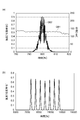
- 18A is a graph showing a spectrum waveform calculated from the spectrogram of FIG. 16B, and FIG. 18B shows a time intensity waveform of output light obtained by Fourier transforming the spectrum waveform of FIG. It is a graph.
- 19A is a graph showing a spectrum waveform calculated from the spectrogram of FIG. 17B, and FIG. 19B is a time intensity waveform of output light obtained by Fourier transforming the spectrum waveform of FIG. It is a graph.
- FIG. 1 is a diagram schematically showing a configuration of a light control apparatus 1A according to an embodiment.
- FIG. 2 is a diagram illustrating a configuration of the optical system 10 included in the light control apparatus 1A.
- the light control apparatus 1A of the present embodiment generates output light Ld having an arbitrary time intensity waveform different from the input light La from the input light La.
- the light control device 1 ⁇ / b> A includes a light source 2, an optical system 10, and a modulation pattern calculation device (data creation device) 20.
- the light source 2 outputs the input light La input to the optical system 10.
- the light source 2 is a laser light source such as a solid laser light source, and the input light La is, for example, coherent pulse light.
- the optical system 10 includes an SLM 14 and receives the control signal SC from the modulation pattern calculation device 20 at the SLM 14.
- the optical system 10 converts the input light La from the light source 2 into output light Ld having an arbitrary time intensity waveform.
- the modulation pattern is data for controlling the SLM 14 and is data in which the intensity of the complex amplitude distribution or the intensity of the phase distribution is output to a file.
- the modulation pattern is, for example, a computer-generated hologram (CGH).
- the optical system 10 includes a diffraction grating 12, a lens 13, an SLM 14, a lens 15, and a diffraction grating 16.
- the diffraction grating 12 is a spectroscopic element in the present embodiment, and is optically coupled to the light source 2.
- the SLM 14 is optically coupled to the diffraction grating 12 via the lens 13.
- the diffraction grating 12 separates the input light La for each wavelength component.
- other optical components such as a prism may be used instead of the diffraction grating 12.
- the input light La is incident on the diffraction grating 12 at an angle, and is split into a plurality of wavelength components.
- the light Lb including the plurality of wavelength components is condensed for each wavelength component by the lens 13 and imaged on the modulation surface of the SLM 14.
- the lens 13 may be a convex lens made of a light transmitting member, or a concave mirror having a concave light reflecting surface.
- the SLM 14 simultaneously performs phase modulation and intensity modulation of the light Lb in order to generate output light Ld having an arbitrary time intensity waveform different from the input light La. Further, the SLM 14 may perform only phase modulation or only intensity modulation.
- the SLM 14 is, for example, a phase modulation type. In one embodiment, the SLM 14 is of the LCOS (Liquid crystal on silicon) type.
- FIG. 3 is a diagram showing the modulation surface 17 of the SLM 14. As shown in FIG. 3, a plurality of modulation regions 17 a are arranged along a certain direction A on the modulation surface 17, and each modulation region 17 a extends in a direction B intersecting the direction A. A direction A is a spectral direction by the diffraction grating 12.
- the modulation surface 17 functions as a Fourier transform surface, and each wavelength component corresponding to the spectrum is incident on each of the plurality of modulation regions 17a.
- the SLM 14 modulates the phase and intensity of each incident wavelength component independently of other wavelength components. Since the SLM 14 of the present embodiment is a phase modulation type, intensity modulation is realized by a phase pattern (phase image) presented on the modulation surface 17.
- Each wavelength component of the modulated light Lc modulated by the SLM 14 is collected at one point on the diffraction grating 16 by the lens 15.
- the lens 15 at this time functions as a condensing optical system that condenses the modulated light Lc.
- the lens 15 may be a convex lens made of a light transmitting member, or a concave mirror having a concave light reflecting surface.
- the diffraction grating 16 functions as a multiplexing optical system, and multiplexes the modulated wavelength components. That is, the plurality of wavelength components of the modulated light Lc are condensed and combined with each other by the lens 15 and the diffraction grating 16 to become output light Ld.
- the region before the lens 15 (spectral region) and the region after the diffraction grating 16 (time region) are in a Fourier transform relationship, and the phase modulation in the spectral region is a time intensity waveform in the time region. Affect. Therefore, the output light Ld has a desired time intensity waveform different from the input light La according to the modulation pattern of the SLM 14.
- FIG. 4A shows a spectrum waveform (spectrum phase G11 and spectrum intensity G12) of the monopulse input light La as an example
- FIG. 4B shows a time intensity waveform of the input light La.
- FIG. 5A shows, as an example, a spectrum waveform (spectrum phase G21 and spectrum intensity G22) of the output light Ld when rectangular wave-like phase spectrum modulation is given in the SLM 14, and FIG.
- the time intensity waveform of the output light Ld is shown.
- 4 (a) and 5 (a) the horizontal axis indicates the wavelength (nm)
- the left vertical axis indicates the intensity value (arbitrary unit) of the intensity spectrum
- the right vertical axis indicates the phase value of the phase spectrum.
- (Rad) is shown.
- 4B and 5B the horizontal axis represents time (femtoseconds), and the vertical axis represents light intensity (arbitrary unit).
- the single pulse of the input light La is converted into a double pulse with higher-order light as the output light Ld.
- the spectrum and waveform shown in FIG. 5 are merely examples, and the time intensity waveform of the output light Ld can be shaped into various shapes by combining various phase spectra and intensity spectra.
- the modulation pattern calculation apparatus 20 is, for example, a personal computer; a smart device such as a smartphone or a tablet terminal; or a computer having a processor such as a cloud server.
- the modulation pattern calculation device 20 is electrically connected to the SLM 14, calculates a phase modulation pattern for bringing the time intensity waveform of the output light Ld closer to a desired waveform, and sends a control signal SC including the phase modulation pattern to the SLM 14. To provide.
- the modulation pattern calculation apparatus 20 of the present embodiment includes a phase pattern for phase modulation that gives a phase spectrum for obtaining a desired waveform to the output light Ld, and an intensity that gives an intensity spectrum for obtaining a desired waveform to the output light Ld.
- a phase pattern including the phase pattern for modulation is presented to the SLM 14.
- the modulation pattern calculation apparatus 20 includes an arbitrary waveform input unit 21, a phase spectrum design unit 22, an intensity spectrum design unit 23, and a modulation pattern generation unit (data generation unit) 24. That is, the processor of the computer provided in the modulation pattern calculation apparatus 20 has the function of the arbitrary waveform input unit 21, the function of the phase spectrum design unit 22, the function of the intensity spectrum design unit 23, and the function of the modulation pattern generation unit 24. And realize. Each function may be realized by the same processor or may be realized by different processors.
- the computer processor can realize the above functions by a modulation pattern calculation program (data creation program). Therefore, the modulation pattern calculation program causes the computer processor to operate as the arbitrary waveform input unit 21, phase spectrum design unit 22, intensity spectrum design unit 23, and modulation pattern generation unit 24 in the modulation pattern calculation device 20.
- the modulation pattern calculation program is stored in a storage device (storage medium) inside or outside the computer.
- the storage device may be a non-transitory recording medium.
- the recording medium include a recording medium such as a flexible disk, a CD, and a DVD, a recording medium such as a ROM, a semiconductor memory, a cloud server, and the like.
- the arbitrary waveform input unit 21 receives an input of a desired time intensity waveform from the operator.
- the operator inputs information related to a desired time intensity waveform (for example, pulse width) to the arbitrary waveform input unit 21.
- Information on the desired time intensity waveform is given to the phase spectrum design unit 22 and the intensity spectrum design unit 23.
- the phase spectrum design unit 22 calculates the phase spectrum of the corresponding output light Ld based on the time intensity waveform.
- the intensity spectrum design unit 23 calculates the intensity spectrum of the corresponding output light Ld based on the time intensity waveform.
- the modulation pattern generation unit 24 provides a phase modulation pattern (for example, a computer-generated hologram) for providing the output light Ld with the phase spectrum obtained by the phase spectrum design unit 22 and the intensity spectrum obtained by the intensity spectrum design unit 23. Is calculated. Then, a control signal SC including the calculated phase modulation pattern is provided to the SLM 14, and the SLM 14 is controlled based on the control signal SC.
- a phase modulation pattern for example, a computer-generated hologram
- FIG. 6 is a block diagram showing the internal configuration of the phase spectrum design unit 22 and the intensity spectrum design unit 23.
- the phase spectrum design unit 22 and the intensity spectrum design unit 23 include a Fourier transform unit 25, a function replacement unit 26, a waveform function modification unit 27, an inverse Fourier transform unit 28, and a target generation unit 29.
- the target generation unit 29 includes a Fourier transform unit 29a and a spectrogram correction unit 29b. The functions of these components will be described in detail later.
- the desired time intensity waveform is represented as a function in the time domain
- the phase spectrum is represented as a function in the frequency domain. Accordingly, the phase spectrum corresponding to the desired time intensity waveform is obtained by, for example, an iterative Fourier transform based on the desired time intensity waveform.
- FIG. 7 is a diagram showing a calculation procedure of the phase spectrum by the iterative Fourier transform method.
- an initial intensity spectrum function A 0 ( ⁇ ) and a phase spectrum function ⁇ 0 ( ⁇ ), which are functions of the frequency ⁇ , are prepared (processing number (1) in the figure).
- these intensity spectrum functions A 0 ( ⁇ ) and phase spectrum functions ⁇ 0 ( ⁇ ) represent the spectrum intensity and the spectrum phase of the input light La, respectively.
- a waveform function (a) in the frequency domain including the intensity spectrum function A 0 ( ⁇ ) and the phase spectrum function ⁇ n ( ⁇ ) is prepared (processing number (2) in the figure).
- the subscript n represents after the nth Fourier transform processing.
- the above-described initial phase spectrum function ⁇ 0 ( ⁇ ) is used as the phase spectrum function ⁇ n ( ⁇ ). i is an imaginary number.
- a Fourier transform from the frequency domain to the time domain is performed on the function (a) (arrow A1 in the figure).
- a frequency domain waveform function (b) including the time intensity waveform function b n (t) and the time phase waveform function ⁇ n (t) is obtained (process number (3) in the figure).
- time intensity waveform function b n (t) included in the function (b) is replaced with a time intensity waveform function Target 0 (t) based on a desired waveform (process numbers (4) and (5) in the figure. )).
- the function is replaced with the initial intensity spectrum function A 0 ( ⁇ ) (process number (7) in the figure).
- phase spectrum shape represented by the phase spectrum function ⁇ n ( ⁇ ) in the waveform function is converted into the phase spectrum shape corresponding to the desired time intensity waveform.
- the finally obtained phase spectrum function ⁇ IFTA ( ⁇ ) is the basis of a modulation pattern for obtaining a desired time intensity waveform.
- the iterative Fourier method as described above can control the time intensity waveform, but has a problem that the frequency component (band wavelength) constituting the time intensity waveform cannot be controlled.
- the output light Ld includes a plurality of light pulses
- the wavelength can be varied for each light pulse, it can be applied to various devices such as a laser processing device, an ultrahigh-speed imaging camera, and a terahertz wave generation device.
- the modulation pattern calculation apparatus 20 calculates the phase spectrum function and the intensity spectrum function that are the basis of the modulation pattern using the calculation method described below.
- FIG. 8 is a diagram showing a calculation procedure of the phase spectrum function in the phase spectrum design unit 22.
- an initial intensity spectrum function A 0 ( ⁇ ) and a phase spectrum function ⁇ 0 ( ⁇ ), which are functions of the frequency ⁇ , are prepared (processing number (1) in the figure).
- these intensity spectrum functions A 0 ( ⁇ ) and phase spectrum functions ⁇ 0 ( ⁇ ) represent the spectrum intensity and the spectrum phase of the input light La, respectively.
- a first waveform function (g) in the frequency domain including the intensity spectrum function A 0 ( ⁇ ) and the phase spectrum function ⁇ 0 ( ⁇ ) is prepared (processing number (2-a)).
- i is an imaginary number.
- the Fourier transform unit 25 of the phase spectrum design unit 22 performs a Fourier transform from the frequency domain to the time domain for the function (g) (arrow A3 in the figure).
- the second waveform function (h) in the time domain including the time intensity waveform function a 0 (t) and the time phase waveform function ⁇ 0 (t) is obtained (Fourier transform step, process number (3)).
- the function replacement unit 26 of the phase spectrum design unit 22 obtains a desired waveform input from the arbitrary waveform input unit 21 to the time intensity waveform function b 0 (t) as shown in the following formula (i).
- the time intensity waveform function Target 0 (t) based on the above is substituted (processing number (4-a)).
- the function replacing unit 26 of the phase spectrum designing unit 22 replaces the time intensity waveform function a 0 (t) with the time intensity waveform function b 0 (t) as shown in the following mathematical formula (j). That is, the time intensity waveform function a 0 (t) included in the function (h) is replaced with a time intensity waveform function Target 0 (t) based on a desired waveform (function replacement step, process number (5)).
- the waveform function correcting unit 27 of the phase spectrum designing unit 22 changes the second waveform function so that the spectrogram of the replaced second waveform function (j) approaches the target spectrogram generated in advance according to the desired wavelength band. Correct it.
- the second waveform function (j) is converted into a spectrogram SG 0, k ( ⁇ , t) by performing time-frequency conversion on the replaced second waveform function (j) (processing in the figure). Number (5-a)).
- the subscript k represents the k-th conversion process.
- the time-frequency conversion is a frequency filter process or a numerical calculation process (a process of deriving a spectrum for each time by multiplying a window function while shifting a composite signal such as a time waveform). Is converted into three-dimensional information composed of time, frequency, and signal component strength (spectral intensity).
- the conversion result time, frequency, spectrum intensity
- spectrogram the conversion result
- time-frequency transform examples include short-time Fourier transform (STFT) and wavelet transform (Haar wavelet transform, Gabor wavelet transform, Mexican hat wavelet transform, and Morley wavelet transform).
- STFT short-time Fourier transform
- wavelet transform Harmonic wavelet transform, Gabor wavelet transform, Mexican hat wavelet transform, and Morley wavelet transform
- the target spectrogram TargetSG 0 ( ⁇ , t) generated in advance according to the desired wavelength band is read from the target generation unit 29.
- This target spectrogram TargetSG 0 ( ⁇ , t) is substantially the same value as the target time waveform (time intensity waveform and frequency components constituting it), and is generated in the target spectrogram function of the process number (5-b). .
- the waveform function correction unit 27 of the phase spectrum design unit 22 performs pattern matching between the spectrogram SG 0, k ( ⁇ , t) and the target spectrogram TargetSG 0 ( ⁇ , t), and the degree of similarity (how much coincides with each other). To check).
- an evaluation value is calculated as an index representing the degree of similarity.
- the time phase waveform function ⁇ 0 (t) included in the second waveform function is changed to an arbitrary time phase waveform function ⁇ 0, k (t).
- the second waveform function after changing the time phase waveform function is converted back to a spectrogram by time-frequency conversion such as STFT.
- the process numbers (5-a) to (5-c) described above are repeatedly performed.
- the second waveform function is corrected so that the spectrogram SG 0, k ( ⁇ , t) gradually approaches the target spectrogram TargetSG 0 ( ⁇ , t) (waveform function correcting step).
- the inverse Fourier transform unit 28 of the phase spectrum design unit 22 performs inverse Fourier transform on the corrected second waveform function (arrow A4 in the figure) to generate a third waveform function (k) in the frequency domain.
- the phase spectrum function ⁇ 0, k ( ⁇ ) included in the third waveform function (k) is the desired phase spectrum function ⁇ TWC-TFD ( ⁇ ) that is finally obtained.
- This phase spectrum function ⁇ TWC-TFD ( ⁇ ) is provided to the modulation pattern generation unit 24.
- FIG. 9 is a diagram showing a calculation procedure of the spectrum intensity in the intensity spectrum design unit 23. Since the process number (1) to the process number (5-c) are the same as the spectrum phase calculation procedure in the phase spectrum design unit 22 described above, the description thereof is omitted.
- the waveform function correction unit 27 of the intensity spectrum design unit 23 determines that the evaluation value indicating the similarity between the spectrogram SG 0, k ( ⁇ , t) and the target spectrogram TargetSG 0 ( ⁇ , t) does not satisfy a predetermined termination condition. While the time phase waveform function ⁇ 0 (t) included in the second waveform function is constrained by the initial value, the time intensity waveform function b 0 (t) is changed to an arbitrary time intensity waveform function b 0, k (t). (Processing number (5-e)). The second waveform function after changing the time intensity waveform function is converted back to a spectrogram by time-frequency conversion such as STFT.
- the process numbers (5-a) to (5-c) are repeatedly performed.
- the second waveform function is corrected so that the spectrogram SG 0, k ( ⁇ , t) gradually approaches the target spectrogram TargetSG 0 ( ⁇ , t) (waveform function correcting step).
- the inverse Fourier transform unit 28 of the intensity spectrum design unit 23 performs inverse Fourier transform on the corrected second waveform function (arrow A4 in the figure) to generate a third waveform function (m) in the frequency domain. (Inverse Fourier transform step, process number (6)).
- the filter processing unit of the intensity spectrum design unit 23 applies the input light La to the intensity spectrum function B 0, k ( ⁇ ) included in the third waveform function (m). Filter processing based on the intensity spectrum is performed (filter processing step). Specifically, the part of the intensity spectrum obtained by multiplying the intensity spectrum function B 0, k ( ⁇ ) by the coefficient ⁇ exceeds the cutoff intensity for each wavelength determined based on the intensity spectrum of the input light La. . This is to prevent the intensity spectrum function ⁇ B 0, k ( ⁇ ) from exceeding the spectrum intensity of the input light La in all wavelength regions.
- the cutoff intensity for each wavelength is set to match the intensity spectrum of the input light La (in this embodiment, the initial intensity spectrum function A 0 ( ⁇ )).
- the intensity spectrum function A TWC-TFD ( ⁇ ) is obtained at a frequency where the intensity spectrum function ⁇ B 0, k ( ⁇ ) is larger than the intensity spectrum function A 0 ( ⁇ ).
- the value of the intensity spectrum function A 0 ( ⁇ ) is taken as the value of.
- the intensity spectrum function ⁇ B 0, k ( ⁇ ) is the intensity spectrum function A frequency is 0 (omega) or less, the intensity spectrum function A TWC-TFD intensity spectrum as a value of (omega) function ⁇ B 0, k ( ⁇ ) Is taken in (process number (7-b) in the figure).
- This intensity spectrum function A TWC-TFD ( ⁇ ) is provided to the modulation pattern generation unit 24 as a desired desired spectrum intensity.
- the modulation pattern generation unit 24 uses the spectrum phase indicated by the phase spectrum function ⁇ TWC-TFD ( ⁇ ) calculated by the phase spectrum design unit 22 and the intensity spectrum function A TWC-TFD (A phase modulation pattern (for example, a computer-generated hologram) for giving the spectrum intensity indicated by ⁇ ) to the output light Ld is calculated (data generation step).
- ⁇ TWC-TFD phase spectrum function
- a phase modulation pattern for example, a computer-generated hologram
- FIG. 10 is a diagram illustrating an example of a generation procedure of the target spectrogram TargetSG 0 ( ⁇ , t) in the target generation unit 29. Since the target spectrogram TargetSG 0 ( ⁇ , t) indicates a target time waveform (time intensity waveform and frequency components (wavelength band components) constituting the time waveform), a target spectrogram is created by using frequency components (wavelength band components). This is an extremely important process for controlling the process.
- the target generation unit 29 first has a spectrum waveform (initial intensity spectrum function A 0 ( ⁇ ) and initial phase spectrum function ⁇ 0 ( ⁇ )), and a desired time intensity waveform function Target 0. Enter (t). Further, a time function p 0 (t) including desired frequency (wavelength) band information is input (process number (1)).
- the target generation unit 29 uses the iterative Fourier transform method shown in FIG. 7 or the method described in Non-Patent Document 1 or 2 to realize the time intensity waveform function Target 0 (t), for example.
- the phase spectrum function ⁇ IFTA ( ⁇ ) is calculated (process number (2)).
- FIG. 11 is a diagram illustrating an example of a procedure for calculating the intensity spectrum function A IFTA ( ⁇ ).
- a waveform function (o) in the frequency domain including the intensity spectrum function A k ( ⁇ ) and the phase spectrum function ⁇ 0 ( ⁇ ) is prepared (process number (2) in the figure).
- the subscript k represents after the k-th Fourier transform processing.
- time intensity waveform function b k (t) included in the function (p) is replaced with a time intensity waveform function Target 0 (t) based on a desired waveform (process numbers (4) and (5) in the figure. )).
- phase spectrum function ⁇ k ( ⁇ ) included in the function (s) is replaced with the initial phase spectrum function ⁇ 0 ( ⁇ ) (process number (7-a) in the figure).
- a filtering process based on the intensity spectrum of the input light La is performed on the intensity spectrum function C k ( ⁇ ) in the frequency domain after the inverse Fourier transform. Specifically, the portion of the intensity spectrum represented by the intensity spectrum function C k ( ⁇ ) that exceeds the cutoff intensity for each wavelength determined based on the intensity spectrum of the input light La is cut.
- the value of the intensity spectrum function C k ( ⁇ ) is taken as the value of the intensity spectrum function A k ( ⁇ ).
- the intensity spectrum shape represented by the intensity spectrum function A k ( ⁇ ) in the waveform function is changed to the intensity spectrum shape corresponding to the desired time intensity waveform. Can be approached. Finally, the intensity spectrum function A IFTA ( ⁇ ) is obtained.
- the Fourier transform unit 29a of the target generation unit 29 performs Fourier transform on the above waveform function (v). Thereby, the 4th waveform function (w) of a time domain is obtained (process number (5)).
- the spectrogram correcting unit 29b of the target generating unit 29 converts the fourth waveform function (w) into the spectrogram SG IFTA ( ⁇ , t) by time-frequency conversion (processing number (6)).
- the target spectrogram TargetSG 0 ( ⁇ , t) is corrected by correcting the spectrogram SG IFTA ( ⁇ , t) based on the time function p 0 (t) including desired frequency (wavelength) band information. t).
- a characteristic pattern appearing in a spectrogram SG IFTA ( ⁇ , t) composed of two-dimensional data is partially cut out, and the frequency component of the portion is manipulated based on the time function p 0 (t). Specific examples thereof will be described in detail below.
- the spectrogram SG IFTA ( ⁇ , t) has a result as shown in FIG. 12A, the horizontal axis represents time (unit: femtosecond), and the vertical axis represents wavelength (unit: nm).
- the spectrogram value is indicated by the brightness of the figure. The brighter the value, the greater the spectrogram value.
- the triple pulse appears as domains D 1 , D 2 , and D 3 divided on the time axis at intervals of 2 picoseconds.
- the center (peak) wavelength of domains D 1 , D 2 , and D 3 is 800 nm.
- the spectrogram SG IFTA ( ⁇ , t) changes to the target spectrogram TargetSG 0 ( ⁇ , t) shown in FIG.
- a target spectrogram in which the constituent frequency (wavelength band) of each pulse is arbitrarily controlled can be created without changing the shape of the time intensity waveform.
- the modulation pattern calculation device data creation device 20
- the light control device 1A the modulation pattern calculation method (data creation method)
- the modulation pattern calculation method data creation method
- the computer-generated hologram computer-generated hologram
- the modulation pattern calculation program data creation program
- the second waveform function (h) is generated after generating the second waveform function (h) in the time domain by performing Fourier transform on the first waveform function (g) in the frequency domain.
- the time intensity waveform function Target 0 (t) based on the desired waveform is replaced.
- an inverse Fourier transform is performed on the second waveform function to generate third waveform functions (k) and (m) in the frequency domain.
- a modulation pattern is generated based on the phase spectrum function ⁇ 0, k ( ⁇ ) of the third waveform function (k) and the intensity spectrum function B 0, k ( ⁇ ) of the third waveform function (m).
- a modulation pattern for realizing a desired waveform can be suitably generated.
- the spectrogram SG 0, k (2) of the second waveform function is added to the target spectrogram Target SG 0 ( ⁇ , t).
- the second waveform function is corrected so that ⁇ , t) approaches.
- the target spectrogram TargetSG 0 ( ⁇ , t) is generated in advance according to the desired wavelength band, and the wavelength band of the second waveform function is corrected to the desired wavelength band by this process. Accordingly, the third waveform functions (k) and (m) obtained by inverse Fourier transform of the second waveform function are also functions within a desired wavelength band.
- the modulation pattern is based on the phase spectrum function ⁇ 0, k ( ⁇ ) of the third waveform function ( k ) and the intensity spectrum function B 0, k ( ⁇ ) of the third waveform function (m). Generated. As described above, according to the present embodiment, it is possible to control the wavelength component (frequency component) of light constituting an arbitrary time intensity waveform.
- the waveform function correcting unit 27 calculates an evaluation value representing the degree of similarity between the spectrogram SG IFTA ( ⁇ , t) of the second waveform function and the target spectrogram TargetSG 0 ( ⁇ , t).
- the second waveform function may be modified so that the evaluation value satisfies a predetermined condition. For example, with this method, the second waveform function can be accurately corrected so that the spectrogram SG IFTA ( ⁇ , t) of the second waveform function approaches the target spectrogram TargetSG 0 ( ⁇ , t).
- the waveform function correcting unit 27 uses the time intensity waveform function b 0, k (t) or the time phase waveform function ⁇ 0, k (t) to correct the second waveform function. It may be changed.
- the second waveform function can be suitably corrected so that the spectrogram SG IFTA ( ⁇ , t) of the second waveform function approaches the target spectrogram TargetSG 0 ( ⁇ , t).
- the phase spectrum design unit 22 calculates the phase spectrum function ⁇ TWC-TFD ( ⁇ )
- the intensity spectrum design unit 23 calculates the intensity spectrum function A TWC-TFD ( ⁇ )
- the unit 24 generates a modulation pattern based on both functions.
- the modulation pattern generation unit generates one of the phase spectrum function ⁇ TWC-TFD ( ⁇ ) and the intensity spectrum function A TWC-TFD ( ⁇ ). Based on this, a modulation pattern may be generated.
- time-frequency conversion when the waveform function correcting unit 27 converts the second waveform function into the spectrogram SG 0, k ( ⁇ , t) (the processing number (5-a) in FIGS. 8 and 9),
- short-time Fourier transform (STFT) and wavelet transform are illustrated. What is important in the time-frequency conversion process is to convert a time waveform into a spectrogram SG 0, k ( ⁇ , t) which is “time-frequency information”.
- this embodiment mainly controls frequency components (band component) which constitute the time waveform. This is because it is meaningful to extract time intensity information and frequency (band) information from the time waveform. That is, the time-frequency conversion is not limited to STFT and wavelet conversion, and various conversion processes that can extract frequency information from a time waveform can be applied.
- the waveform function correcting unit 27 uses the evaluation values indicating the similarity between the spectrogram SG IFTA ( ⁇ , t) of the second waveform function and the target spectrogram TargetSG 0 ( ⁇ , t). Are close to each other (process number (5-c) in FIGS. 8 and 9).
- the target spectrogram TargetSG 0 ( ⁇ , t) represents what time intensity shape and frequency (band) information the desired time waveform includes, and so to speak, serves as a target value (design drawing). Therefore, the evaluation value of this embodiment can be one of the indexes indicating the waveform control accuracy.
- the spectrogram SG IFTA ( ⁇ , t) since the spectrogram SG IFTA ( ⁇ , t) includes two variables such as the frequency ⁇ and the time t, it can be handled as an image. Therefore, examining how much the spectrogram SG IFTA ( ⁇ , t) matches the target spectrogram TargetSG 0 ( ⁇ , t) is a difference extraction operation using various pattern matching techniques in image analysis. Can think.
- a method of extracting a feature amount of an image (such as a contour or shape limited to a frequency or a time axis direction) and evaluating a pattern matching degree
- a method of dividing an image into a plurality of parts and evaluating each part can also be applied.
- the waveform function correcting unit 27 does not satisfy the predetermined condition (the spectrogram SG IFTA ( ⁇ , t) and the target spectrogram TargetSG 0 ( ⁇ , t) are different).
- the time phase waveform function ⁇ 0, k (t) or the time intensity waveform function b 0, k (t) is changed to another arbitrary one (the processing number (5-d) in FIG. 8 and the processing in FIG. 9). Number (5-e)).
- the index may be used.
- the magnitude of the evaluation value calculated in the process number (5-a) and the determination result in the process number (5-c) are changed to the functions ⁇ 0, k (t) and b 0, k (t).
- a new spectrogram NewSG 0 ( ⁇ , t) is created based on the difference value between the spectrogram SG IFTA ( ⁇ , t) and the target spectrogram TargetSG 0 ( ⁇ , t), and the new SG 0 ( ⁇ , T) is transformed into a time waveform by inverse spectrogram transformation.
- the target generation unit 29 when the target generation unit 29 generates the target spectrogram TargetSG 0 ( ⁇ , t), the phase spectrum function for realizing the time intensity waveform function Target 0 (t) in the process number (2) shown in FIG. ⁇ IFTA ( ⁇ ) is calculated.
- the iterative Fourier transform method shown in FIG. 7 or the method described in Non-Patent Document 1 or 2 can be used, but the calculation method of the phase spectrum function ⁇ IFTA ( ⁇ ) is The phase spectrum function ⁇ IFTA ( ⁇ ) obtained analytically or approximately so as to realize the generation of the time intensity waveform function Target 0 (t) is not limited thereto .
- the target generation unit 29 when the target generation unit 29 generates the target spectrogram TargetSG 0 ( ⁇ , t), in the processing number (3) shown in FIG. 10, the intensity spectrum function for realizing the time intensity waveform function Target 0 (t).
- a IFTA ( ⁇ ) is calculated.
- the method of calculating the has been described an example of calculating an improved iterative Fourier transform method intensity spectrum function A IFTA using (omega) above, the intensity spectral function A IFTA ( ⁇ )
- the intensity spectrum function A IFTA ( ⁇ ) obtained analytically or approximately so as to realize generation of the time intensity waveform function Target 0 (t) may be used.
- a modulation pattern (for example, a computer-generated hologram) is created based on the modulation pattern calculation method (data creation method) of the present embodiment using a computer that exists in a remote place such as a cloud server, and the created modulation pattern Data about the may be sent to the user.
- a modulation pattern for example, a computer-generated hologram
- ( ⁇ , t) was prepared. Specifically, combinations of center wavelengths (peak wavelengths) of two domains are (800 nm, 800 nm), (801 nm, 799 nm), (802 nm, 798 nm), (803 nm, 797 nm), and (804 nm, 796 nm), respectively.
- Five types of target spectrograms TargetSG 0 ( ⁇ , t) were prepared. Then, the phase spectrum function ⁇ TWC-TFD ( ⁇ ) was calculated using the method shown in FIG. 8, and the intensity spectrum function A TWC-TFD ( ⁇ ) was calculated using the method shown in FIG.
- FIG. 13 shows the center wavelengths of the two domains included in each spectrogram SG 0, k ( ⁇ , t) whose evaluation values satisfy a predetermined condition for each corresponding target spectrogram TargetSG 0 ( ⁇ , t). It is a graph which shows the center wavelength space
- Graphs G31 and G32 are straight lines connecting the center wavelengths of one and the other domains included in the target spectrogram TargetSG 0 ( ⁇ , t), respectively, and graphs G33 and G34 are spectrograms SG 0, k ( ⁇ , t ) Are approximate curves connecting the center wavelengths of one and the other domains.
- the time waveform including the frequency (wavelength) band can be controlled when the wavelength band difference between adjacent pulses is within 4 nm, for example. That is, it was shown that the change to an arbitrary wavelength band is generally possible within the range of the full width at half maximum (5 nm) of the wavelength band of the input light La. In other words, when moving the domain of the target spectrogram TargetSG ( ⁇ , t) in the wavelength axis direction, it is desirable to move within the wavelength band of the input light La.
- FIG. 14A was obtained using the method shown in FIGS. 8 and 9 with the combination of the center wavelengths of the two domains of the target spectrogram TargetSG ( ⁇ , t) set to (800 nm, 800 nm). It is a graph which shows a spectrum waveform (spectrum phase G41 and spectrum intensity G42).
- FIG. 14B is a graph showing a time intensity waveform of the output light Ld obtained by Fourier transforming the spectrum waveform of FIG.
- FIG. 15A is obtained using the method shown in FIGS. 8 and 9 with the combination of the center wavelengths of the two domains of the target spectrogram TargetSG ( ⁇ , t) set to (802 nm, 798 nm). It is a graph which shows the obtained spectrum waveform (spectrum phase G51 and spectrum intensity G52).
- FIG. 15B is a graph showing a time intensity waveform of the output light Ld obtained by Fourier transforming the spectrum waveform of FIG.
- FIGS. 16A and 17A show the target spectrogram TargetSG ( ⁇ , t) used in this example.
- FIG. 16A shows a case where the wavelength bands of the pulses are not controlled (equalized), and
- FIG. 17A shows a case where the wavelength bands of the pulses are different from each other.
- FIGS. 16B and 17B show spectrograms SG 0, k ( ⁇ , t) calculated based on the target spectrogram TargetSG ( ⁇ , t) in FIGS. 16A and 17A, respectively. t).
- the horizontal axis represents time (unit: femtosecond), and the vertical axis represents wavelength (unit: nm).
- the spectrogram value is indicated by the brightness of the figure. The brighter the value, the greater the spectrogram value.
- the target spectrogram TargetSG ( ⁇ , t) and the spectrogram SG 0, k ( ⁇ , t) include the same number of domains D 1 to D 7 as the number of pulses.
- FIG. 18A shows the spectrum waveform (spectrum phase G61 and spectrum intensity G62) calculated from the time waveform (second waveform function) corresponding to the spectrogram SG 0, k ( ⁇ , t) of FIG. It is a graph to show.
- FIG. 18B is a graph showing a time intensity waveform of the output light Ld obtained by Fourier transforming the spectrum waveform of FIG.
- FIG. 19A shows a spectrum waveform (spectrum phase G71 and spectrum intensity G72) calculated from a time waveform (second waveform function) corresponding to the spectrogram SG 0, k ( ⁇ , t) of FIG. ).
- FIG. 19B is a graph showing a time intensity waveform of the output light Ld obtained by Fourier transforming the spectrum waveform of FIG.
- FIG. 18A and FIG. 19A when the central wavelengths of the domains are equal to each other (FIG. 18A), the central wavelengths of the domains are different from each other (FIG. 19A). It can be seen that there is a clear difference in the phase spectrum of the output light Ld. On the other hand, comparing FIG. 18B and FIG. 19B, it can be seen that the same time intensity waveform can be obtained regardless of the control of the frequency (wavelength) band of the output light Ld.
- the data creation device, the light control device, the data creation method, and the data creation program are not limited to the above-described embodiments, and various other modifications are possible.
- an optical system diffraction grating 12 and lens 13
- an optical system (lens 15 and diffraction grating 16) that generate output light
- the optical system may be common.
- the SLM is preferably of a reflective type.
- the data creation device is a device for creating data for controlling the spatial light modulator, and performs Fourier transform on the first waveform function in the frequency domain including the intensity spectrum function and the phase spectrum function, and the time
- a Fourier transform unit that generates a second waveform function in a time domain including an intensity waveform function and a time phase waveform function
- a function replacement unit that replaces a time intensity waveform function based on a desired waveform for the second waveform function
- a waveform function correcting unit that corrects the second waveform function so that the spectrogram of the second waveform function approaches a target spectrogram generated in advance according to the desired waveform and the desired wavelength band, and the inverse of the corrected second waveform function
- An inverse Fourier transform unit that performs a Fourier transform and generates a third waveform function in the frequency domain, and an intensity spectrum function or a third waveform function. It has a configuration comprising a data generation unit for generating data based on the phase spectrum function.
- the data creation method is a method of creating data for controlling the spatial light modulator, which performs Fourier transform on the first waveform function in the frequency domain including the intensity spectrum function and the phase spectrum function, A Fourier transform step of generating a time domain second waveform function including an intensity waveform function and a time phase waveform function; a function replacement step of replacing the second waveform function with a time intensity waveform function based on a desired waveform; A waveform function correcting step for correcting the second waveform function so that the spectrogram of the second waveform function approaches the target spectrogram generated in advance according to the desired waveform and the desired wavelength band, and reverse with respect to the corrected second waveform function An inverse Fourier transform step for performing a Fourier transform and generating a third waveform function in the frequency domain; It has a data generating step of generating data on the basis of the intensity spectrum function or phase spectrum function, configured to include.
- the data creation program is a program for creating data for controlling the spatial light modulator, which performs Fourier transform on the first waveform function in the frequency domain including the intensity spectrum function and the phase spectrum function, A Fourier transform step of generating a time domain second waveform function including an intensity waveform function and a time phase waveform function; a function replacement step of replacing the second waveform function with a time intensity waveform function based on a desired waveform; A waveform function correcting step for correcting the second waveform function so that the spectrogram of the second waveform function approaches the target spectrogram generated in advance according to the desired waveform and the desired wavelength band, and reverse with respect to the corrected second waveform function An inverse Fourier transform step for performing a Fourier transform and generating a third waveform function in the frequency domain; It has a configuration to execute a data generating step of generating data on the basis of the intensity spectrum function or phase spectrum function of the third waveform function, to the computer.
- the waveform function correcting unit calculates an evaluation value representing the similarity between the spectrogram of the second waveform function and the target spectrogram, and evaluates it.
- the second waveform function may be modified so that the value satisfies a predetermined condition. For example, with this method, the second waveform function can be accurately corrected so that the spectrogram of the second waveform function approaches the target spectrogram.
- the waveform function modification unit changes the time intensity waveform function or the time phase waveform function in order to modify the second waveform function. It is good also as a structure.
- the second waveform function can be suitably corrected so that the spectrogram of the second waveform function approaches the target spectrogram.
- the data generation device, the data generation method, and the data generation program further include a target generation unit (target generation step) that generates a target spectrogram, and the target generation unit (target generation step) is for realizing a desired waveform.
- a target generation unit for performing a Fourier transform on the third waveform function in the frequency domain including the intensity spectrum function and the phase spectrum function of the first to generate a fourth waveform function in the time domain including the time intensity waveform function and the time phase waveform function ( (Fourier transform step) and a spectrogram correcting unit (spectrogram correcting step) for correcting the wavelength band of the spectrogram of the fourth waveform function in accordance with a desired wavelength band.
- a target generation unit target generation step
- the data generation method the data generation method, and the data generation program
- a target spectrogram can be suitably generated in advance.
- the light source that outputs the input light, the spectroscopic element that splits the input light, and the intensity spectrum or the phase spectrum of the input light after the spectrum are modulated, and the modulated light
- a spatial light modulator and an optical system that collects the modulated light, and the spatial light modulator is an intensity spectrum or phase spectrum of the input light based on the data calculated by the data creation device having the above configuration. It is set as the structure which modulates at least any one of these.
- the computer-generated hologram according to the above embodiment is created by the data creation method having the above configuration. If the spatial light modulator is controlled by this computer-generated hologram, the wavelength component (frequency component) of the light constituting the time intensity waveform can be controlled.
- the embodiment can be used as a data creation device, a light control device, a data creation method, and a data creation program capable of controlling the wavelength component (frequency component) of light constituting a time intensity waveform.
- SYMBOLS 1A Light control apparatus, 2 ... Light source, 10 ... Optical system, 12, 16 ... Diffraction grating, 13, 15 ... Lens, 14 ... SLM, 17 ... Modulation surface, 17a ... Modulation area
Landscapes
- Physics & Mathematics (AREA)
- Nonlinear Science (AREA)
- Optics & Photonics (AREA)
- General Physics & Mathematics (AREA)
- Electromagnetism (AREA)
- Engineering & Computer Science (AREA)
- Plasma & Fusion (AREA)
- Optical Modulation, Optical Deflection, Nonlinear Optics, Optical Demodulation, Optical Logic Elements (AREA)
- Spectrometry And Color Measurement (AREA)
Abstract
強度スペクトル関数及び位相スペクトル関数を含む周波数領域の第1波形関数に対してフーリエ変換を行い、時間強度波形関数及び時間位相波形関数を含む時間領域の第2波形関数を生成する。第2波形関数に対し、所望の波形に基づく時間強度波形関数の置き換えを行う。所望の波長帯域に従って予め生成されたターゲットスペクトログラムに第2波形関数のスペクトログラムが近づくように、第2波形関数を修正する。修正後の第2波形関数に対して逆フーリエ変換を行い、周波数領域の第3波形関数を生成する。第3波形関数の強度スペクトル関数又は位相スペクトル関数に基づいてデータを生成する。これにより、時間強度波形を構成する光の波長成分(周波数成分)を制御することが可能となる。
Description
本開示は、データ作成装置、光制御装置、データ作成方法、及びデータ作成プログラムに関するものである。
非特許文献1には、空間光変調器(Spatial Light Modulator:SLM)を用いて位相スペクトルを変調することにより、光パルスを成形する技術が開示されている。この文献では、所望の光パルス波形を得るための位相スペクトルを、反復フーリエ法を用いて算出している。
M. Hacker, G. Stobrawa, T. Feurer, "Iterative Fourier transform algorithm for phase-only pulse shaping", Optics Express, Vol. 9, No. 4, pp.191-199, 2001
Olivier Ripoll, Ville Kettunen, Hans Peter Herzig, "Review of iterative Fourier-transform algorithms for beam shaping applications", Optical Engineering, Vol. 43, No. 11, pp.2549-2556, 2004
例えば超短パルス光といった種々の光の時間波形を制御するための技術として、光パルスの位相スペクトル及び強度スペクトルをSLMによって変調するものがある。このような技術では、光の時間強度波形を所望の波形に近づけるための位相スペクトル及び強度スペクトルを算出し、その位相スペクトル及び強度スペクトルを光に与えるための変調パターンをSLMに呈示させる。
しかしながら、従来のこのような技術においては、時間強度波形の形状の制御しかできず、時間強度波形を構成する光の波長成分(周波数成分)を制御することはできない。例えば、複数のパルスを含む出力光を生成する場合、複数のパルス毎に波長を異ならせることができれば、レーザ加工装置、超高速撮像カメラ、テラヘルツ波発生装置など様々な装置への応用が可能となる。
実施形態は、時間強度波形を構成する光の波長成分(周波数成分)を制御することが可能なデータ作成装置、光制御装置、データ作成方法、及びデータ作成プログラムを提供することを目的とする。
本発明の実施形態は、データ作成装置である。データ作成装置は、空間光変調器を制御するデータを作成する装置であって、強度スペクトル関数及び位相スペクトル関数を含む周波数領域の第1波形関数に対してフーリエ変換を行い、時間強度波形関数及び時間位相波形関数を含む時間領域の第2波形関数を生成するフーリエ変換部と、第2波形関数に対し、所望の波形に基づく時間強度波形関数の置き換えを行う関数置換部と、所望の波形及び所望の波長帯域に従って予め生成されたターゲットスペクトログラムに第2波形関数のスペクトログラムが近づくように第2波形関数を修正する波形関数修正部と、修正後の第2波形関数に対して逆フーリエ変換を行い、周波数領域の第3波形関数を生成する逆フーリエ変換部と、第3波形関数の強度スペクトル関数又は位相スペクトル関数に基づいてデータを生成するデータ生成部と、を備える。
本発明の実施形態は、データ作成方法である。データ作成方法は、空間光変調器を制御するデータを作成する方法であって、強度スペクトル関数及び位相スペクトル関数を含む周波数領域の第1波形関数に対してフーリエ変換を行い、時間強度波形関数及び時間位相波形関数を含む時間領域の第2波形関数を生成するフーリエ変換ステップと、第2波形関数に対し、所望の波形に基づく時間強度波形関数の置き換えを行う関数置換ステップと、所望の波形及び所望の波長帯域に従って予め生成されたターゲットスペクトログラムに第2波形関数のスペクトログラムが近づくように第2波形関数を修正する波形関数修正ステップと、修正後の第2波形関数に対して逆フーリエ変換を行い、周波数領域の第3波形関数を生成する逆フーリエ変換ステップと、第3波形関数の強度スペクトル関数又は位相スペクトル関数に基づいてデータを生成するデータ生成ステップと、を含む。
本発明の実施形態は、データ作成プログラムである。データ作成プログラムは、空間光変調器を制御するデータを作成するプログラムであって、強度スペクトル関数及び位相スペクトル関数を含む周波数領域の第1波形関数に対してフーリエ変換を行い、時間強度波形関数及び時間位相波形関数を含む時間領域の第2波形関数を生成するフーリエ変換ステップと、第2波形関数に対し、所望の波形に基づく時間強度波形関数の置き換えを行う関数置換ステップと、所望の波形及び所望の波長帯域に従って予め生成されたターゲットスペクトログラムに第2波形関数のスペクトログラムが近づくように第2波形関数を修正する波形関数修正ステップと、修正後の第2波形関数に対して逆フーリエ変換を行い、周波数領域の第3波形関数を生成する逆フーリエ変換ステップと、第3波形関数の強度スペクトル関数又は位相スペクトル関数に基づいてデータを生成するデータ生成ステップと、をコンピュータに実行させる。
これらの装置、方法、及びプログラムにおいては、周波数領域の第1波形関数に対してフーリエ変換を行うことにより時間領域の第2波形関数を生成したのち、第2波形関数に対し、所望の波形に基づく時間強度波形関数の置き換えを行う。時間強度波形関数の置き換えののち、逆フーリエ変換の前に、ターゲットスペクトログラムに第2波形関数のスペクトログラムが近づくように第2波形関数を修正する。
このターゲットスペクトログラムは所望の波形及び所望の波長帯域に従って予め生成されたものであり、この処理によって、第2波形関数の波長帯域は、所望の波長帯域に修正される。従って、第2波形関数を逆フーリエ変換して得られる第3波形関数もまた、所望の波長帯域内の関数となる。そして、空間光変調器を制御するデータは、第3波形関数の強度スペクトル関数又は位相スペクトル関数に基づいて生成される。以上より、上記の装置、方法、及びプログラムによれば、時間強度波形を構成する光の波長成分(周波数成分)を制御することが可能となる。
また、別の実施形態は、光制御装置である。光制御装置は、入力光を出力する光源と、入力光を分光する分光素子と、分光後の入力光の強度スペクトルもしくは位相スペクトルの少なくともいずれか一方を変調し、変調光を出力する空間光変調器と、変調光を集光する光学系と、を備え、空間光変調器は、上記構成のデータ作成装置により作成されたデータに基づいて入力光の強度スペクトルもしくは位相スペクトルの少なくともいずれか一方を変調する。
この光制御装置によれば、上記構成のデータ作成装置により作成されたデータに基づいて空間光変調器を制御することによって、時間強度波形を構成する光の波長成分(周波数成分)を制御することが可能となる。
実施形態によるデータ作成装置、光制御装置、データ作成方法、及びデータ作成プログラムによれば、時間強度波形を構成する光の波長成分(周波数成分)を制御することができる。
以下、添付図面を参照しながら、データ作成装置、光制御装置、データ作成方法、及びデータ作成プログラムの実施の形態を詳細に説明する。なお、図面の説明において同一の要素には同一の符号を付し、重複する説明を省略する。
図1は、一実施形態に係る光制御装置1Aの構成を概略的に示す図である。図2は、光制御装置1Aが備える光学系10の構成を示す図である。本実施形態の光制御装置1Aは、入力光Laから、該入力光Laとは異なる任意の時間強度波形を有する出力光Ldを生成する。図1に示されるように、光制御装置1Aは、光源2、光学系10、及び変調パターン算出装置(データ作成装置)20を備える。
光源2は、光学系10に入力される入力光Laを出力する。光源2は例えば固体レーザ光源等のレーザ光源であり、入力光Laは例えばコヒーレントなパルス光である。光学系10は、SLM14を有しており、変調パターン算出装置20からの制御信号SCをSLM14に受ける。光学系10は、光源2からの入力光Laを、任意の時間強度波形を有する出力光Ldに変換する。変調パターンは、SLM14を制御するためのデータであり、複素振幅分布の強度あるいは位相分布の強度をファイルに出力されたデータである。変調パターンは、例えば、計算機合成ホログラム(Computer-Generated Hologram:CGH)である。
図2に示されるように、光学系10は、回折格子12、レンズ13、SLM14、レンズ15、及び回折格子16を有する。回折格子12は本実施形態における分光素子であり、光源2と光学的に結合されている。SLM14はレンズ13を介して回折格子12と光学的に結合されている。回折格子12は、入力光Laを波長成分毎に分光する。なお、分光素子として、回折格子12に代えてプリズム等の他の光学部品を用いてもよい。入力光Laは、回折格子12に対して斜めに入射し、複数の波長成分に分光される。この複数の波長成分を含む光Lbは、レンズ13によって各波長成分毎に集光され、SLM14の変調面に結像される。レンズ13は、光透過部材からなる凸レンズであってもよく、凹状の光反射面を有する凹面鏡であってもよい。
SLM14は、入力光Laとは異なる任意の時間強度波形を有する出力光Ldを生成するために、光Lbの位相変調と強度変調とを同時に行う。また、SLM14は、位相変調のみ、または強度変調のみを行ってもよい。SLM14は、例えば位相変調型である。一実施例では、SLM14はLCOS(Liquid crystal on silicon)型である。
図3は、SLM14の変調面17を示す図である。図3に示されるように、変調面17には、複数の変調領域17aが或る方向Aに沿って並んでおり、各変調領域17aは方向Aと交差する方向Bに延びている。方向Aは、回折格子12による分光方向である。この変調面17はフーリエ変換面として働き、複数の変調領域17aのそれぞれには、分光後の対応する各波長成分が入射する。SLM14は、各変調領域17aにおいて、入射した各波長成分の位相及び強度を他の波長成分から独立して変調する。なお、本実施形態のSLM14は位相変調型であるため、強度変調は、変調面17に呈示される位相パターン(位相画像)によって実現される。
SLM14によって変調された変調光Lcの各波長成分は、レンズ15によって回折格子16上の一点に集められる。このときのレンズ15は、変調光Lcを集光する集光光学系として機能する。レンズ15は、光透過部材からなる凸レンズであってもよく、凹状の光反射面を有する凹面鏡であってもよい。また、回折格子16は合波光学系として機能し、変調後の各波長成分を合波する。すなわち、これらのレンズ15及び回折格子16により、変調光Lcの複数の波長成分は互いに集光・合波されて出力光Ldとなる。
レンズ15よりも前の領域(スペクトル領域)と、回折格子16よりも後ろの領域(時間領域)とは、互いにフーリエ変換の関係にあり、スペクトル領域における位相変調は、時間領域における時間強度波形に影響する。従って、出力光Ldは、SLM14の変調パターンに応じた、入力光Laとは異なる所望の時間強度波形を有することとなる。
ここで、図4(a)は、一例として、単パルス状の入力光Laのスペクトル波形(スペクトル位相G11及びスペクトル強度G12)を示し、図4(b)は、該入力光Laの時間強度波形を示す。また、図5(a)は、一例として、SLM14において矩形波状の位相スペクトル変調を与えたときの出力光Ldのスペクトル波形(スペクトル位相G21及びスペクトル強度G22)を示し、図5(b)は、該出力光Ldの時間強度波形を示す。図4(a)及び図5(a)において、横軸は波長(nm)を示し、左の縦軸は強度スペクトルの強度値(任意単位)を示し、右の縦軸は位相スペクトルの位相値(rad)を示す。また、図4(b)及び図5(b)において、横軸は時間(フェムト秒)を表し、縦軸は光強度(任意単位)を表す。
この例では、矩形波状の位相スペクトル波形を出力光Ldに与えることにより、入力光Laのシングルパルスが、出力光Ldとして高次光を伴うダブルパルスに変換されている。なお、図5に示されるスペクトル及び波形は一つの例であって、様々な位相スペクトル及び強度スペクトルの組み合わせにより、出力光Ldの時間強度波形を様々な形状に整形することができる。
再び図1を参照する。変調パターン算出装置20は、例えば、パーソナルコンピュータ;スマートフォン、タブレット端末などのスマートデバイス;あるいはクラウドサーバなどのプロセッサを有するコンピュータである。変調パターン算出装置20は、SLM14と電気的に接続されており、出力光Ldの時間強度波形を所望の波形に近づけるための位相変調パターンを算出し、該位相変調パターンを含む制御信号SCをSLM14に提供する。
本実施形態の変調パターン算出装置20は、所望の波形を得る為の位相スペクトルを出力光Ldに与える位相変調用の位相パターンと、所望の波形を得る為の強度スペクトルを出力光Ldに与える強度変調用の位相パターンとを含む位相パターンをSLM14に呈示させる。そのために、変調パターン算出装置20は、任意波形入力部21と、位相スペクトル設計部22と、強度スペクトル設計部23と、変調パターン生成部(データ生成部)24とを有する。すなわち、変調パターン算出装置20に設けられたコンピュータのプロセッサは、任意波形入力部21の機能と、位相スペクトル設計部22の機能と、強度スペクトル設計部23の機能と、変調パターン生成部24の機能とを実現する。それぞれの機能は、同じプロセッサにより実現されてもよいし、異なるプロセッサにより実現されてもよい。
コンピュータのプロセッサは、変調パターン算出プログラム(データ作成プログラム)によって、上記の各機能を実現することができる。故に、変調パターン算出プログラムは、コンピュータのプロセッサを、変調パターン算出装置20における任意波形入力部21、位相スペクトル設計部22、強度スペクトル設計部23、及び変調パターン生成部24として動作させる。
変調パターン算出プログラムは、コンピュータの内部または外部の記憶装置(記憶媒体)に記憶される。記憶装置は、非一時的記録媒体であってもよい。記録媒体としては、フレキシブルディスク、CD、DVD等の記録媒体、ROM等の記録媒体、半導体メモリ、クラウドサーバ等が例示される。
任意波形入力部21は、操作者からの所望の時間強度波形の入力を受け付ける。操作者は、所望の時間強度波形に関する情報(例えばパルス幅など)を任意波形入力部21に入力する。所望の時間強度波形に関する情報は、位相スペクトル設計部22及び強度スペクトル設計部23に与えられる。位相スペクトル設計部22は、その時間強度波形に基づいて、対応する出力光Ldの位相スペクトルを算出する。強度スペクトル設計部23は、その時間強度波形に基づいて、対応する出力光Ldの強度スペクトルを算出する。
変調パターン生成部24は、位相スペクトル設計部22において求められた位相スペクトルと、強度スペクトル設計部23において求められた強度スペクトルとを出力光Ldに与えるための位相変調パターン(例えば、計算機合成ホログラム)を算出する。そして、算出された位相変調パターンを含む制御信号SCが、SLM14に提供され、SLM14は、制御信号SCに基づいて制御される。
図6は、位相スペクトル設計部22及び強度スペクトル設計部23の内部構成を示すブロック図である。図6に示されるように、位相スペクトル設計部22及び強度スペクトル設計部23は、フーリエ変換部25、関数置換部26、波形関数修正部27、逆フーリエ変換部28、及びターゲット生成部29を有する。ターゲット生成部29は、フーリエ変換部29a及びスペクトログラム修正部29bを含む。これらの各構成要素の機能については、後に詳述する。
ここで、所望の時間強度波形は時間領域の関数として表され、位相スペクトルは周波数領域の関数として表される。従って、所望の時間強度波形に対応する位相スペクトルは、例えば、所望の時間強度波形に基づく反復フーリエ変換によって得られる。図7は、反復フーリエ変換法による位相スペクトルの計算手順を示す図である。
まず、周波数ωの関数である初期の強度スペクトル関数A0(ω)及び位相スペクトル関数Ψ0(ω)を用意する(図中の処理番号(1))。一例では、これらの強度スペクトル関数A0(ω)及び位相スペクトル関数Ψ0(ω)はそれぞれ入力光Laのスペクトル強度及びスペクトル位相を表す。次に、強度スペクトル関数A0(ω)及び位相スペクトル関数Ψn(ω)を含む周波数領域の波形関数(a)を用意する(図中の処理番号(2))。

添え字nは、第n回目のフーリエ変換処理後を表す。最初(第1回目)のフーリエ変換処理の前においては、位相スペクトル関数Ψn(ω)として上述した初期の位相スペクトル関数Ψ0(ω)が用いられる。iは虚数である。
続いて、上記関数(a)に対して周波数領域から時間領域へのフーリエ変換を行う(図中の矢印A1)。これにより、時間強度波形関数bn(t)及び時間位相波形関数Θn(t)を含む周波数領域の波形関数(b)が得られる(図中の処理番号(3))。

続いて、上記関数(b)に含まれる時間強度波形関数bn(t)を、所望の波形に基づく時間強度波形関数Target0(t)に置き換える(図中の処理番号(4)、(5))。


続いて、上記関数(d)に対して時間領域から周波数領域への逆フーリエ変換を行う(図中の矢印A2)。これにより、強度スペクトル関数Bn(ω)及び位相スペクトル関数Ψn(ω)を含む周波数領域の波形関数(e)が得られる(図中の処理番号(6))。

続いて、上記関数(e)に含まれる強度スペクトル関数Bn(ω)を拘束するため、初期の強度スペクトル関数A0(ω)に置き換える(図中の処理番号(7))。

以降、上記の処理(1)~(7)を複数回繰り返し行うことにより、波形関数中の位相スペクトル関数Ψn(ω)が表す位相スペクトル形状を、所望の時間強度波形に対応する位相スペクトル形状に近づけることができる。最終的に得られる位相スペクトル関数ΨIFTA(ω)が、所望の時間強度波形を得るための変調パターンの基になる。
しかしながら、上述したような反復フーリエ法では、時間強度波形を制御することはできるが、時間強度波形を構成する周波数成分(帯域波長)を制御することはできないという問題がある。例えば出力光Ldが複数の光パルスを含む場合、光パルス毎に波長を異ならせることができれば、レーザ加工装置、超高速撮像カメラ、テラヘルツ波発生装置など様々な装置への応用が可能となる。
そこで、本実施形態の変調パターン算出装置20は、以下に説明する算出方法を用いて、変調パターンの基になる位相スペクトル関数及び強度スペクトル関数を算出する。図8は、位相スペクトル設計部22における位相スペクトル関数の計算手順を示す図である。
まず、周波数ωの関数である初期の強度スペクトル関数A0(ω)及び位相スペクトル関数Φ0(ω)を用意する(図中の処理番号(1))。一例では、これらの強度スペクトル関数A0(ω)及び位相スペクトル関数Φ0(ω)はそれぞれ入力光Laのスペクトル強度及びスペクトル位相を表す。次に、強度スペクトル関数A0(ω)及び位相スペクトル関数Φ0(ω)を含む周波数領域の第1波形関数(g)を用意する(処理番号(2-a))。但し、iは虚数である。

続いて、位相スペクトル設計部22のフーリエ変換部25は、上記関数(g)に対して周波数領域から時間領域へのフーリエ変換を行う(図中の矢印A3)。これにより、時間強度波形関数a0(t)及び時間位相波形関数φ0(t)を含む時間領域の第2波形関数(h)が得られる(フーリエ変換ステップ、処理番号(3))。

続いて、位相スペクトル設計部22の関数置換部26は、次の数式(i)に示されるように、時間強度波形関数b0(t)に、任意波形入力部21において入力された所望の波形に基づく時間強度波形関数Target0(t)を代入する(処理番号(4-a))。

続いて、位相スペクトル設計部22の関数置換部26は、次の数式(j)に示されるように、時間強度波形関数a0(t)を時間強度波形関数b0(t)で置き換える。すなわち、上記関数(h)に含まれる時間強度波形関数a0(t)を、所望の波形に基づく時間強度波形関数Target0(t)に置き換える(関数置換ステップ、処理番号(5))。

続いて、位相スペクトル設計部22の波形関数修正部27は、置き換え後の第2波形関数(j)のスペクトログラムが、所望の波長帯域に従って予め生成されたターゲットスペクトログラムに近づくように第2波形関数を修正する。まず、置き換え後の第2波形関数(j)に対して時間-周波数変換を施すことにより、第2波形関数(j)をスペクトログラムSG0,k(ω,t)に変換する(図中の処理番号(5-a))。添え字kは、第k回目の変換処理を表す。
ここで、時間-周波数変換とは、時間波形のような複合信号に対して、周波数フィルタ処理または数値演算処理(窓関数をずらしながら乗算して、各々の時間に対してスペクトルを導出する処理)を施し、時間、周波数、信号成分の強さ(スペクトル強度)からなる3次元情報に変換することをいう。また、本実施形態では、その変換結果(時間、周波数、スペクトル強度)を「スペクトログラム」と定義する。
時間-周波数変換としては、例えば、短時間フーリエ変換(Short-Time Fourier Transform:STFT)やウェーブレット変換(ハールウェーブレット変換、ガボールウェーブレット変換、メキシカンハットウェーブレット変換、モルレーウェーブレット変換)などがある。
また、所望の波長帯域に従って予め生成されたターゲットスペクトログラムTargetSG0(ω,t)をターゲット生成部29から読み出す。このターゲットスペクトログラムTargetSG0(ω,t)は、目標とする時間波形(時間強度波形とそれを構成する周波数成分)と概ね同値であり、処理番号(5-b)のターゲットスペクトログラム関数において生成される。
次に、位相スペクトル設計部22の波形関数修正部27は、スペクトログラムSG0,k(ω,t)とターゲットスペクトログラムTargetSG0(ω,t)とのパターンマッチングを行い、類似度(どの程度一致しているか)を調べる。本実施形態では、類似度を表す指標として、評価値を算出する。そして、続く処理番号(5-c)では、得られた評価値が、所定の終了条件を満たすか否かの判定を行う。条件を満たせば処理番号(6)へ進み、満たさなければ処理番号(5-d)へ進む。処理番号(5-d)では、第2波形関数に含まれる時間位相波形関数φ0(t)を任意の時間位相波形関数φ0,k(t)に変更する。時間位相波形関数を変更した後の第2波形関数は、STFTなどの時間-周波数変換により再びスペクトログラムに変換される。
以降、上述した処理番号(5-a)~(5-c)が繰り返し行われる。こうして、スペクトログラムSG0,k(ω,t)がターゲットスペクトログラムTargetSG0(ω,t)に次第に近づくように、第2波形関数が修正される(波形関数修正ステップ)。
その後、位相スペクトル設計部22の逆フーリエ変換部28は、修正後の第2波形関数に対して逆フーリエ変換を行い(図中の矢印A4)、周波数領域の第3波形関数(k)を生成する(逆フーリエ変換ステップ、処理番号(6))。

この第3波形関数(k)に含まれる位相スペクトル関数Φ0,k(ω)が、最終的に得られる所望の位相スペクトル関数ΦTWC-TFD(ω)となる。この位相スペクトル関数ΦTWC-TFD(ω)が、変調パターン生成部24に提供される。
図9は、強度スペクトル設計部23におけるスペクトル強度の計算手順を示す図である。なお、処理番号(1)から処理番号(5-c)までは、上述した位相スペクトル設計部22におけるスペクトル位相の計算手順と同様なので説明を省略する。
強度スペクトル設計部23の波形関数修正部27は、スペクトログラムSG0,k(ω,t)とターゲットスペクトログラムTargetSG0(ω,t)との類似度を示す評価値が所定の終了条件を満たさない場合、第2波形関数に含まれる時間位相波形関数φ0(t)は初期値で拘束しつつ、時間強度波形関数b0(t)を任意の時間強度波形関数b0,k(t)に変更する(処理番号(5-e))。時間強度波形関数を変更した後の第2波形関数は、STFTなどの時間-周波数変換により再びスペクトログラムに変換される。
以降、処理番号(5-a)~(5-c)が繰り返し行われる。こうして、スペクトログラムSG0,k(ω,t)がターゲットスペクトログラムTargetSG0(ω,t)に次第に近づくように、第2波形関数が修正される(波形関数修正ステップ)。
その後、強度スペクトル設計部23の逆フーリエ変換部28は、修正後の第2波形関数に対して逆フーリエ変換を行い(図中の矢印A4)、周波数領域の第3波形関数(m)を生成する(逆フーリエ変換ステップ、処理番号(6))。

続いて、処理番号(7-b)では、強度スペクトル設計部23のフィルタ処理部が、第3波形関数(m)に含まれる強度スペクトル関数B0,k(ω)に対し、入力光Laの強度スペクトルに基づくフィルタ処理を行う(フィルタ処理ステップ)。具体的には、強度スペクトル関数B0,k(ω)に係数αを乗じた強度スペクトルのうち、入力光Laの強度スペクトルに基づいて定められる各波長毎のカットオフ強度を超える部分をカットする。全ての波長域において、強度スペクトル関数αB0,k(ω)が入力光Laのスペクトル強度を超えないようにするためである。
一例では、波長毎のカットオフ強度は、入力光Laの強度スペクトル(本実施形態では初期の強度スペクトル関数A0(ω))と一致するように設定される。その場合、次の数式(n)に示されるように、強度スペクトル関数αB0,k(ω)が強度スペクトル関数A0(ω)よりも大きい周波数では、強度スペクトル関数ATWC-TFD(ω)の値として強度スペクトル関数A0(ω)の値が取り入れられる。また、強度スペクトル関数αB0,k(ω)が強度スペクトル関数A0(ω)以下である周波数では、強度スペクトル関数ATWC-TFD(ω)の値として強度スペクトル関数αB0,k(ω)の値が取り入れられる(図中の処理番号(7-b))。

この強度スペクトル関数ATWC-TFD(ω)が、最終的に得られる所望のスペクトル強度として変調パターン生成部24に提供される。
変調パターン生成部24は、位相スペクトル設計部22において算出された位相スペクトル関数ΦTWC-TFD(ω)により示されるスペクトル位相と、強度スペクトル設計部23において算出された強度スペクトル関数ATWC-TFD(ω)により示されるスペクトル強度とを出力光Ldに与えるための位相変調パターン(例えば、計算機合成ホログラム)を算出する(データ生成ステップ)。
ここで、図10は、ターゲット生成部29におけるターゲットスペクトログラムTargetSG0(ω,t)の生成手順の一例を示す図である。ターゲットスペクトログラムTargetSG0(ω,t)は、目標とする時間波形(時間強度波形とそれを構成する周波数成分(波長帯域成分))を示すので、ターゲットスペクトログラムの作成は、周波数成分(波長帯域成分)を制御するために極めて重要な工程である。
図10に示されるように、ターゲット生成部29は、まずスペクトル波形(初期の強度スペクトル関数A0(ω)及び初期の位相スペクトル関数Φ0(ω))、並びに所望の時間強度波形関数Target0(t)を入力する。また、所望の周波数(波長)帯域情報を含む時間関数p0(t)を入力する(処理番号(1))。
次に、ターゲット生成部29は、例えば図7に示された反復フーリエ変換法、或いは非特許文献1または2に記載された方法を用いて、時間強度波形関数Target0(t)を実現するための位相スペクトル関数ΦIFTA(ω)を算出する(処理番号(2))。
続いて、ターゲット生成部29は、先に得られた位相スペクトル関数ΦIFTA(ω)を利用した反復フーリエ変換法により、時間強度波形関数Target0(t)を実現するための強度スペクトル関数AIFTA(ω)を算出する(処理番号(3))。ここで、図11は、強度スペクトル関数AIFTA(ω)を算出する手順の一例を示す図である。
まず、初期の強度スペクトル関数Ak=0(ω)及び位相スペクトル関数Ψ0(ω)を用意する(図中の処理番号(1))。次に、強度スペクトル関数Ak(ω)及び位相スペクトル関数Ψ0(ω)を含む周波数領域の波形関数(o)を用意する(図中の処理番号(2))。
添え字kは、第k回目のフーリエ変換処理後を表す。最初(第1回目)のフーリエ変換処理の前においては、強度スペクトル関数Ak(ω)として上記の初期強度スペクトル関数Ak=0(ω)が用いられる。iは虚数である。
続いて、上記関数(o)に対して周波数領域から時間領域へのフーリエ変換を行う(図中の矢印A5)。これにより、時間強度波形関数bk(t)を含む周波数領域の波形関数(p)が得られる(図中の処理番号(3))。

続いて、上記関数(p)に含まれる時間強度波形関数bk(t)を、所望の波形に基づく時間強度波形関数Target0(t)に置き換える(図中の処理番号(4)、(5))。


続いて、上記関数(r)に対して時間領域から周波数領域への逆フーリエ変換を行う(図中の矢印A6)。これにより、強度スペクトル関数Ck(ω)及び位相スペクトル関数Ψk(ω)を含む周波数領域の波形関数(s)が得られる(図中の処理番号(6))。

続いて、上記関数(s)に含まれる位相スペクトル関数Ψk(ω)を拘束するため、初期の位相スペクトル関数Ψ0(ω)に置き換える(図中の処理番号(7-a))。

また、逆フーリエ変換後の周波数領域における強度スペクトル関数Ck(ω)に対し、入力光Laの強度スペクトルに基づくフィルタ処理を行う。具体的には、強度スペクトル関数Ck(ω)により表される強度スペクトルのうち、入力光Laの強度スペクトルに基づいて定められる各波長毎のカットオフ強度を超える部分をカットする。
一例では、波長毎のカットオフ強度は、入力光Laの強度スペクトル(例えば初期の強度スペクトル関数Ak=0(ω))と一致するように設定される。その場合、次の数式(u)に示されるように、強度スペクトル関数Ck(ω)が強度スペクトル関数Ak=0(ω)よりも大きい周波数では、強度スペクトル関数Ak(ω)の値として強度スペクトル関数Ak=0(ω)の値が取り入れられる。また、強度スペクトル関数Ck(ω)が強度スペクトル関数Ak=0(ω)以下である周波数では、強度スペクトル関数Ak(ω)の値として強度スペクトル関数Ck(ω)の値が取り入れられる(図中の処理番号(7-b))。

上記関数(s)に含まれる強度スペクトル関数Ck(ω)を、上記数式(u)によるフィルタ処理後の強度スペクトル関数Ak(ω)に置き換える。
以降、上記の処理(1)~(7-b)を繰り返し行うことにより、波形関数中の強度スペクトル関数Ak(ω)が表す強度スペクトル形状を、所望の時間強度波形に対応する強度スペクトル形状に近づけることができる。最終的に、強度スペクトル関数AIFTA(ω)が得られる。
再び図10を参照する。以上に説明した処理番号(2)、(3)における位相スペクトル関数ΦIFTA(ω)及び強度スペクトル関数AIFTA(ω)の算出によって、これらの関数を含む周波数領域の第3波形関数(v)が得られる(処理番号(4))。

ターゲット生成部29のフーリエ変換部29aは、上の波形関数(v)をフーリエ変換する。これにより、時間領域の第4波形関数(w)が得られる(処理番号(5))。

ターゲット生成部29のスペクトログラム修正部29bは、時間-周波数変換により第4波形関数(w)をスペクトログラムSGIFTA(ω,t)に変換する(処理番号(6))。そして、処理番号(7)では、所望の周波数(波長)帯域情報を含む時間関数p0(t)を基にスペクトログラムSGIFTA(ω,t)を修正することにより、ターゲットスペクトログラムTargetSG0(ω,t)を生成する。例えば、2次元データにより構成されるスペクトログラムSGIFTA(ω,t)に現れる特徴的パターンを部分的に切り出し、時間関数p0(t)を基に当該部分の周波数成分の操作を行う。以下、その具体例について詳細に説明する。
例えば、所望の時間強度波形関数Target0(t)として時間間隔が2ピコ秒であるトリプルパルスを設定した場合について考える。このとき、スペクトログラムSGIFTA(ω,t)は、図12(a)に示されるような結果となる。なお、図12(a)において横軸は時間(単位:フェムト秒)を示し、縦軸は波長(単位:nm)を示す。また、スペクトログラムの値は、図の明暗によって示されており、明るいほどスペクトログラムの値が大きい。このスペクトログラムSGIFTA(ω,t)において、トリプルパルスは2ピコ秒間隔で時間軸上に分かれたドメインD1、D2、及びD3として現れる。ドメインD1、D2、及びD3の中心(ピーク)波長は800nmである。
仮に出力光Ldの時間強度波形のみを制御したい(単にトリプルパルスを得たい)場合には、これらのドメインD1、D2、及びD3を操作する必要はない。しかし、各パルスの周波数(波長)帯域を制御したい場合には、これらのドメインD1、D2、及びD3の操作が必要となる。すなわち、図12(b)に示されるように、波長軸(縦軸)に沿った方向に各ドメインD1、D2、及びD3を互いに独立して移動させることは、それぞれのパルスの構成周波数(波長帯域)を変更することを意味する。このような各パルスの構成周波数(波長帯域)の変更は、時間関数p0(t)を基に行われる。
例えば、ドメインD2のピーク波長を800nmで据え置き、ドメインD1及びD3のピーク波長がそれぞれ-2nm、+2nmだけ平行移動するように時間関数p0(t)を記述するとき、スペクトログラムSGIFTA(ω,t)は、図12(b)に示されるターゲットスペクトログラムTargetSG0(ω,t)に変化する。例えばスペクトログラムにこのような処理を施すことによって、時間強度波形の形状を変えずに、各パルスの構成周波数(波長帯域)が任意に制御されたターゲットスペクトログラムを作成することができる。
以上に説明した、本実施形態による変調パターン算出装置(データ作成装置)20、光制御装置1A、変調パターン算出方法(データ作成方法)、計算機合成ホログラム、及び変調パターン算出プログラム(データ作成プログラム)によって得られる効果について説明する。
前述したとおり、本実施形態では、周波数領域の第1波形関数(g)に対してフーリエ変換を行うことにより時間領域の第2波形関数(h)を生成したのち、第2波形関数(h)に対し、所望の波形に基づく時間強度波形関数Target0(t)の置き換えを行う。その後、第2波形関数に対して逆フーリエ変換を行い、周波数領域の第3波形関数(k)及び(m)を生成する。そして、第3波形関数(k)の位相スペクトル関数Φ0,k(ω)、及び第3波形関数(m)の強度スペクトル関数B0,k(ω)に基づいて変調パターンを生成する。これにより、所望の波形を実現するための変調パターンを好適に生成することができる。
加えて、本実施形態では、時間強度波形関数Target0(t)の置き換えののち、逆フーリエ変換の前に、ターゲットスペクトログラムTargetSG0(ω,t)に第2波形関数のスペクトログラムSG0,k(ω,t)が近づくように第2波形関数を修正する。
このターゲットスペクトログラムTargetSG0(ω,t)は所望の波長帯域に従って予め生成されたものであり、この処理によって、第2波形関数の波長帯域は、所望の波長帯域に修正される。従って、第2波形関数を逆フーリエ変換して得られる第3波形関数(k)及び(m)もまた、所望の波長帯域内の関数となる。そして、上述したように変調パターンは、第3波形関数(k)の位相スペクトル関数Φ0,k(ω)、及び第3波形関数(m)の強度スペクトル関数B0,k(ω)に基づいて生成される。以上より、本実施形態によれば、任意の時間強度波形を構成する光の波長成分(周波数成分)を制御することが可能となる。
また、本実施形態のように、波形関数修正部27は、第2波形関数のスペクトログラムSGIFTA(ω,t)とターゲットスペクトログラムTargetSG0(ω,t)との類似度を表す評価値を算出し、評価値が所定の条件を満たすように第2波形関数を修正してもよい。例えばこのような方式によって、第2波形関数のスペクトログラムSGIFTA(ω,t)がターゲットスペクトログラムTargetSG0(ω,t)に近づくように第2波形関数を精度良く修正することができる。
また、本実施形態のように、波形関数修正部27は、第2波形関数を修正するために、時間強度波形関数b0,k(t)又は時間位相波形関数φ0,k(t)を変更してもよい。例えばこのような方式によって、第2波形関数のスペクトログラムSGIFTA(ω,t)がターゲットスペクトログラムTargetSG0(ω,t)に近づくように第2波形関数を好適に修正することができる。
なお、変調パターン算出装置、変調パターン算出方法、及び変調パターン算出プログラムは、本実施形態に限られるものではなく、様々な変更が可能である。例えば、本実施形態では、位相スペクトル設計部22が位相スペクトル関数ΦTWC-TFD(ω)を算出し、強度スペクトル設計部23が強度スペクトル関数ATWC-TFD(ω)を算出し、変調パターン生成部24が、双方の関数に基づいて変調パターンを生成しているが、変調パターン生成部は、位相スペクトル関数ΦTWC-TFD(ω)及び強度スペクトル関数ATWC-TFD(ω)のうち一方に基づいて変調パターンを生成してもよい。
また、波形関数修正部27が第2波形関数をスペクトログラムSG0,k(ω,t)に変換する際(図8及び図9の処理番号(5-a))の時間-周波数変換として、本実施形態では短時間フーリエ変換(STFT)及びウェーブレット変換を例示している。時間-周波数変換処理において重要なことは、時間波形を「時間-周波数情報」であるスペクトログラムSG0,k(ω,t)へ変換することにある。本実施形態では、時間波形のうち時間強度波形のみを制御する手法(例えば非特許文献1,2)と異なり、その時間波形を構成する周波数成分(帯域成分)を制御することを主な目的としており、時間波形から時間強度情報と周波数(帯域)情報とを抽出することに意味があるからである。つまり、時間-周波数変換としては、STFT及びウェーブレット変換に限らず、時間波形から周波数情報を抽出し得る様々な変換処理を適用することができる。
また、本実施形態では、波形関数修正部27が、第2波形関数のスペクトログラムSGIFTA(ω,t)とターゲットスペクトログラムTargetSG0(ω,t)との類似度を示す評価値を用いて、これらが互いにどの程度近いかを判定している(図8及び図9の処理番号(5-c))。ターゲットスペクトログラムTargetSG0(ω,t)は、所望の時間波形が、どのような時間強度形状及び周波数(帯域)情報を含むかを表すものであり、いわば目標値(設計図)の役割を果たす。従って、本実施形態の評価値は、波形制御精度を示す指標の一つとなり得る。
一方、スペクトログラムSGIFTA(ω,t)は、周波数ω及び時間tといった2つの変数を含むので、画像としても扱うことができる。従って、スペクトログラムSGIFTA(ω,t)とターゲットスペクトログラムTargetSG0(ω,t)とがどの程度一致しているかを調べることは、画像解析における各種のパターンマッチング手法を用いた差違抽出作業であると考えることができる。故に、類似度を示す評価値を利用する方法の他にも、例えば、画像の特徴量(周波数や時間軸方向に限定した輪郭・形状など)を抽出してパターンのマッチング度合いを評価する方法や、画像を複数の部分に分割して部分毎に評価する方法などを適用することもできる。
また、本実施形態では、波形関数修正部27が、評価値が所定の条件を満たさない(スペクトログラムSGIFTA(ω,t)とターゲットスペクトログラムTargetSG0(ω,t)とが乖離している)場合に、時間位相波形関数φ0,k(t)または時間強度波形関数b0,k(t)を他の任意のものへ変更する(図8の処理番号(5-d)、図9の処理番号(5-e))。
これらの関数φ0,k(t)、b0,k(t)を変更する方法としては、様々な方法がある。最も簡易な方法としては、関数φ0,k(t)、b0,k(t)をランダムに変化させる方法がある。また、例えばシミュレーテッドアニーリング法などにより、一定のルールに従い(確率過程に伴い)関数φ0,k(t)、b0,k(t)の解を探索する方法も適用可能である。
或いは、どのような関数φ0,k(t)、b0,k(t)を用いると評価値が良くなるかの指標が得られる場合には、その指標を活用してもよい。例えば、処理番号(5-a)にて算出される評価値の大きさや処理番号(5-c)における判定結果を、関数φ0,k(t)、b0,k(t)の変更の際にフィードバックしてもよい。具体的には、スペクトログラムSGIFTA(ω,t)とターゲットスペクトログラムTargetSG0(ω,t)との差分値を基に、新たなスペクトログラムNewSG0(ω,t)を作成し、そのNewSG0(ω,t)を逆スペクトログラム変換することで、時間波形の形に変形する。このようなスペクトログラム上での演算を経て得られたNewSG0(ω,t)を逆スペクトログラム変換することで得られる時間波形の時間位相や時間強度関数には、例えば、どのような関数φ0,k(t)、b0,k(t)を用いると評価値が良くなるかに関する(スペクトログラム上での演算に基づく)指標が含まれる。従って、適宜この指標を時間位相波形関数φ0,k(t)または時間強度波形関数b0,k(t)の修正にフィードバック利用する手法が考えられる。
また、ターゲット生成部29がターゲットスペクトログラムTargetSG0(ω,t)を生成する際、図10に示される処理番号(2)において、時間強度波形関数Target0(t)を実現するための位相スペクトル関数ΦIFTA(ω)を算出する。このとき、図7に示された反復フーリエ変換法、或いは非特許文献1または2に記載された方法を用い得ることを先に述べたが、位相スペクトル関数ΦIFTA(ω)の算出方法はこれらに限られず、時間強度波形関数Target0(t)の生成を実現し得るような、解析的若しくは近似的に求められる位相スペクトル関数ΦIFTA(ω)を用いても良い。
また、ターゲット生成部29がターゲットスペクトログラムTargetSG0(ω,t)を生成する際、図10に示される処理番号(3)において、時間強度波形関数Target0(t)を実現するための強度スペクトル関数AIFTA(ω)を算出する。このとき、図9に示された、改良された反復フーリエ変換法を用いて強度スペクトル関数AIFTA(ω)を算出する例を先に述べたが、強度スペクトル関数AIFTA(ω)の算出方法はこれに限られず、時間強度波形関数Target0(t)の生成を実現し得るような、解析的若しくは近似的に求められる強度スペクトル関数AIFTA(ω)を用いても良い。
なお、クラウドサーバなどの遠隔地に存在するコンピュータを用いて、本実施形態の変調パターン算出方法(データ作成方法)に基づいて変調パターン(例えば、計算機合成ホログラム)を作成し、作成された変調パターンに関するデータをユーザーに送信してもよい。
(第1実施例)
上記実施形態の変調パターン算出方法(データ作成方法)に基づく計算を行って、周波数(波長)帯域の制御を含めた時間波形の制御が可能であることを確かめた。この計算においては、波長帯域が半値全幅で5nmであるシングルパルスを入力光Laとして設定し、2ピコ秒間隔のダブルパルスを出力光Ldとして設定した。この場合、ターゲットスペクトログラムTargetSG(ω,t)は、2つのドメインを含む。
本実施例では、図12(b)に示された方法により、この2つのドメインを波長軸方向に平行移動した(すなわち各パルスを構成する周波数(波長)帯域を変更した)5つのターゲットスペクトログラムTargetSG(ω,t)を用意した。具体的には、2つのドメインの中心波長(ピーク波長)の組み合わせがそれぞれ(800nm,800nm)、(801nm,799nm)、(802nm,798nm)、(803nm,797nm)、及び(804nm,796nm)である5種類のターゲットスペクトログラムTargetSG0(ω,t)を用意した。そして、図8に示された方法を用いて位相スペクトル関数ΦTWC-TFD(ω)を、図9に示された方法を用いて強度スペクトル関数ATWC-TFD(ω)を、それぞれ算出した。
図13は、対応する各ターゲットスペクトログラムTargetSG0(ω,t)に対して評価値が所定の条件を満足した各スペクトログラムSG0,k(ω,t)に含まれる2つのドメインの中心波長と、ドメイン間の中心波長間隔とを示すグラフである。縦軸は各ドメインの中心波長を示し、横軸はドメイン間の中心波長間隔を示している。また、グラフG31及びG32は、ターゲットスペクトログラムTargetSG0(ω,t)に含まれる一方及び他方のドメインの中心波長をそれぞれ結ぶ直線であり、グラフG33及びG34は、スペクトログラムSG0,k(ω,t)に含まれる一方及び他方のドメインの中心波長をそれぞれ結ぶ近似曲線である。
この結果から、隣接するパルスの波長帯域差が例えば4nm以内であるときに、周波数(波長)帯域を含めた時間波形の制御が可能であることが示された。すなわち、入力光Laの波長帯域の半値全幅(5nm)の範囲内において、任意の波長帯域への変更が概ね可能であることが示された。言い換えれば、ターゲットスペクトログラムTargetSG(ω,t)のドメインを波長軸方向に移動する際、入力光Laの波長帯域内で移動することが望ましい。
図14(a)は、ターゲットスペクトログラムTargetSG(ω,t)の2つのドメインの中心波長の組み合わせを(800nm,800nm)と設定し、図8、図9に示された方法を用いて得られたスペクトル波形(スペクトル位相G41及びスペクトル強度G42)を示すグラフである。図14(b)は、図14(a)のスペクトル波形をフーリエ変換して得られた出力光Ldの時間強度波形を示すグラフである。また、図15(a)は、ターゲットスペクトログラムTargetSG(ω,t)の2つのドメインの中心波長の組み合わせを(802nm,798nm)と設定し、図8、図9に示された方法を用いて得られたスペクトル波形(スペクトル位相G51及びスペクトル強度G52)を示すグラフである。図15(b)は、図15(a)のスペクトル波形をフーリエ変換して得られた出力光Ldの時間強度波形を示すグラフである。
図14(a)と図15(a)とを比較すると、各ドメインの中心波長が800nm,800nmである場合(図14(a))、位相スペクトル(G41)はステップ状であり、且つ、強度スペクトル(G42)の裾付近の波長において位相スペクトル(G41)に折り返しが生じている。これに対し、各ドメインの中心波長が802nm,798nmである場合(図15(a))、スペクトル強度(G52)の裾付近の波長に近づくに従って位相スペクトル(G51)のステップが滑らかになり、且つ、位相スペクトル(G51)の折り返しが生じていない。このことから、出力光Ldの周波数(波長)帯域を制御するために、出力光Ldの位相スペクトルに明確な違いが生じることがわかる。
また、図14(b)と図15(b)とを比較すると、出力光Ldの周波数(波長)帯域の制御の違いにかかわらず、同様の時間強度波形が得られることがわかる。
(第2実施例)
続いて、7本のパルスを有する出力光Ldを生成し、各パルスの波長帯域を互いに異ならせる実施例について説明する。図16(a)及び図17(a)は、本実施例にて用いられたターゲットスペクトログラムTargetSG(ω,t)を示す。図16(a)は各パルスの波長帯域を制御しない(等しくする)場合を示し、図17(a)は各パルスの波長帯域を互いに異ならせた場合を示す。また、図16(b)及び図17(b)は、それぞれ図16(a)及び図17(a)のターゲットスペクトログラムTargetSG(ω,t)に基づいて算出されたスペクトログラムSG0,k(ω,t)である。
なお、これらの図において、横軸は時間(単位:フェムト秒)を示し、縦軸は波長(単位:nm)を示す。また、スペクトログラムの値は、図の明暗によって示されており、明るいほどスペクトログラムの値が大きい。本実施例では、ターゲットスペクトログラムTargetSG(ω,t)及びスペクトログラムSG0,k(ω,t)が、パルスの本数と同じ数のドメインD1~D7を含んでいる。
図18(a)は、図16(b)のスペクトログラムSG0,k(ω,t)に対応する時間波形(第2波形関数)から算出されたスペクトル波形(スペクトル位相G61及びスペクトル強度G62)を示すグラフである。図18(b)は、図18(a)のスペクトル波形をフーリエ変換して得られた出力光Ldの時間強度波形を示すグラフである。また、図19(a)は、図17(b)のスペクトログラムSG0,k(ω,t)に対応する時間波形(第2波形関数)から算出されたスペクトル波形(スペクトル位相G71及びスペクトル強度G72)を示すグラフである。図19(b)は、図19(a)のスペクトル波形をフーリエ変換して得られた出力光Ldの時間強度波形を示すグラフである。
図18(a)と図19(a)とを比較すると、各ドメインの中心波長が互いに等しい場合(図18(a))と、各ドメインの中心波長が互いに異なる場合(図19(a))とで、出力光Ldの位相スペクトルに明確な違いが生じることがわかる。一方、図18(b)と図19(b)とを比較すると、出力光Ldの周波数(波長)帯域の制御の違いにかかわらず、同様の時間強度波形が得られることがわかる。
データ作成装置、光制御装置、データ作成方法、及びデータ作成プログラムは、上述した実施形態に限られるものではなく、他に様々な変形が可能である。例えば、上記実施形態では入力光をSLMへ導く光学系(回折格子12及びレンズ13)と、出力光を生成する光学系(レンズ15及び回折格子16)とを別個に設けているが、これらの光学系は共通であってもよい。その場合、SLMは反射型であることが好ましい。
上記実施形態によるデータ作成装置では、空間光変調器を制御するデータを作成する装置であって、強度スペクトル関数及び位相スペクトル関数を含む周波数領域の第1波形関数に対してフーリエ変換を行い、時間強度波形関数及び時間位相波形関数を含む時間領域の第2波形関数を生成するフーリエ変換部と、第2波形関数に対し、所望の波形に基づく時間強度波形関数の置き換えを行う関数置換部と、所望の波形及び所望の波長帯域に従って予め生成されたターゲットスペクトログラムに第2波形関数のスペクトログラムが近づくように第2波形関数を修正する波形関数修正部と、修正後の第2波形関数に対して逆フーリエ変換を行い、周波数領域の第3波形関数を生成する逆フーリエ変換部と、第3波形関数の強度スペクトル関数又は位相スペクトル関数に基づいてデータを生成するデータ生成部と、を備える構成としている。
上記実施形態によるデータ作成方法では、空間光変調器を制御するデータを作成する方法であって、強度スペクトル関数及び位相スペクトル関数を含む周波数領域の第1波形関数に対してフーリエ変換を行い、時間強度波形関数及び時間位相波形関数を含む時間領域の第2波形関数を生成するフーリエ変換ステップと、第2波形関数に対し、所望の波形に基づく時間強度波形関数の置き換えを行う関数置換ステップと、所望の波形及び所望の波長帯域に従って予め生成されたターゲットスペクトログラムに第2波形関数のスペクトログラムが近づくように第2波形関数を修正する波形関数修正ステップと、修正後の第2波形関数に対して逆フーリエ変換を行い、周波数領域の第3波形関数を生成する逆フーリエ変換ステップと、第3波形関数の強度スペクトル関数又は位相スペクトル関数に基づいてデータを生成するデータ生成ステップと、を含む構成としている。
上記実施形態によるデータ作成プログラムでは、空間光変調器を制御するデータを作成するプログラムであって、強度スペクトル関数及び位相スペクトル関数を含む周波数領域の第1波形関数に対してフーリエ変換を行い、時間強度波形関数及び時間位相波形関数を含む時間領域の第2波形関数を生成するフーリエ変換ステップと、第2波形関数に対し、所望の波形に基づく時間強度波形関数の置き換えを行う関数置換ステップと、所望の波形及び所望の波長帯域に従って予め生成されたターゲットスペクトログラムに第2波形関数のスペクトログラムが近づくように第2波形関数を修正する波形関数修正ステップと、修正後の第2波形関数に対して逆フーリエ変換を行い、周波数領域の第3波形関数を生成する逆フーリエ変換ステップと、第3波形関数の強度スペクトル関数又は位相スペクトル関数に基づいてデータを生成するデータ生成ステップと、をコンピュータに実行させる構成としている。
上記のデータ作成装置、データ作成方法、及びデータ作成プログラムにおいて、波形関数修正部(波形関数修正ステップ)は、第2波形関数のスペクトログラムとターゲットスペクトログラムとの類似度を表す評価値を算出し、評価値が所定の条件を満たすように第2波形関数を修正する構成としてもよい。例えばこのような方式によって、第2波形関数のスペクトログラムがターゲットスペクトログラムに近づくように第2波形関数を精度良く修正することができる。
上記のデータ作成装置、データ作成方法、及びデータ作成プログラムにおいて、波形関数修正部(波形関数修正ステップ)は、第2波形関数を修正するために、時間強度波形関数又は時間位相波形関数を変更する構成としてもよい。例えばこのような方式によって、ターゲットスペクトログラムに第2波形関数のスペクトログラムが近づくように第2波形関数を好適に修正することができる。
上記のデータ作成装置、データ作成方法、及びデータ作成プログラムは、ターゲットスペクトログラムを生成するターゲット生成部(ターゲット生成ステップ)を更に備え、ターゲット生成部(ターゲット生成ステップ)は、所望の波形を実現するための強度スペクトル関数及び位相スペクトル関数を含む周波数領域の第3波形関数に対してフーリエ変換を行い、時間強度波形関数及び時間位相波形関数を含む時間領域の第4波形関数を生成するフーリエ変換部(フーリエ変換ステップ)と、第4波形関数のスペクトログラムの波長帯域を、所望の波長帯域に従って修正するスペクトログラム修正部(スペクトログラム修正ステップ)と、を有する構成としてもよい。
データ作成装置、データ作成方法、及びデータ作成プログラムがこのようなターゲット生成部(ターゲット生成ステップ)を備えることによって、予めターゲットスペクトログラムを好適に生成することができる。
また、上記実施形態による光制御装置では、入力光を出力する光源と、入力光を分光する分光素子と、分光後の入力光の強度スペクトルもしくは位相スペクトルの少なくともいずれか一方を変調し、変調光を出力する空間光変調器と、変調光を集光する光学系と、を備え、空間光変調器は、上記構成のデータ作成装置により算出されたデータに基づいて入力光の強度スペクトルもしくは位相スペクトルの少なくともいずれか一方を変調する構成としている。
また、上記実施形態による計算機合成ホログラムは、上記構成のデータ作成方法によって作成される。この計算機合成ホログラムによって空間光変調器を制御すれば、時間強度波形を構成する光の波長成分(周波数成分)を制御することが可能となる。
実施形態は、時間強度波形を構成する光の波長成分(周波数成分)を制御することが可能なデータ作成装置、光制御装置、データ作成方法、及びデータ作成プログラムとして利用可能である。
1A…光制御装置、2…光源、10…光学系、12,16…回折格子、13,15…レンズ、14…SLM、17…変調面、17a…変調領域、20…変調パターン算出装置、21…任意波形入力部、22…位相スペクトル設計部、23…強度スペクトル設計部、24…変調パターン生成部、25…フーリエ変換部、26…関数置換部、27…波形関数修正部、28…逆フーリエ変換部、29…ターゲット生成部、29a…フーリエ変換部、29b…スペクトログラム修正部、D1~D7…ドメイン、La…入力光、Ld…出力光、SC…制御信号。
Claims (7)
- 空間光変調器を制御するデータを作成する装置であって、
強度スペクトル関数及び位相スペクトル関数を含む周波数領域の第1波形関数に対してフーリエ変換を行い、時間強度波形関数及び時間位相波形関数を含む時間領域の第2波形関数を生成するフーリエ変換部と、
前記第2波形関数に対し、所望の波形に基づく前記時間強度波形関数の置き換えを行う関数置換部と、
前記所望の波形及び所望の波長帯域に従って予め生成されたターゲットスペクトログラムに前記第2波形関数のスペクトログラムが近づくように前記第2波形関数を修正する波形関数修正部と、
修正後の前記第2波形関数に対して逆フーリエ変換を行い、周波数領域の第3波形関数を生成する逆フーリエ変換部と、
前記第3波形関数の強度スペクトル関数又は位相スペクトル関数に基づいて前記データを生成するデータ生成部と、
を備える、データ作成装置。 - 前記波形関数修正部は、前記第2波形関数のスペクトログラムと前記ターゲットスペクトログラムとの類似度を表す評価値を算出し、前記評価値が所定の条件を満たすように前記第2波形関数を修正する、請求項1に記載のデータ作成装置。
- 前記波形関数修正部は、前記第2波形関数を修正するために、前記時間強度波形関数又は前記時間位相波形関数を変更する、請求項1または2に記載のデータ作成装置。
- 前記ターゲットスペクトログラムを生成するターゲット生成部を更に備え、
前記ターゲット生成部は、
前記所望の波形を実現するための強度スペクトル関数及び位相スペクトル関数を含む周波数領域の第3波形関数に対してフーリエ変換を行い、時間強度波形関数及び時間位相波形関数を含む時間領域の第4波形関数を生成するフーリエ変換部と、
前記第4波形関数のスペクトログラムの波長帯域を、前記所望の波長帯域に従って修正するスペクトログラム修正部と、
を有する、請求項1~3のいずれか一項に記載のデータ作成装置。 - 入力光を出力する光源と、
前記入力光を分光する分光素子と、
分光後の前記入力光の強度スペクトルもしくは位相スペクトルの少なくともいずれか一方を変調し、変調光を出力する空間光変調器と、
前記変調光を集光する光学系と、
を備え、
前記空間光変調器は、請求項1~4のいずれか一項に記載のデータ作成装置により作成された前記データに基づいて前記入力光の強度スペクトルもしくは位相スペクトルの少なくともいずれか一方を変調する、光制御装置。 - 空間光変調器を制御するデータを作成する方法であって、
強度スペクトル関数及び位相スペクトル関数を含む周波数領域の第1波形関数に対してフーリエ変換を行い、時間強度波形関数及び時間位相波形関数を含む時間領域の第2波形関数を生成するフーリエ変換ステップと、
前記第2波形関数に対し、所望の波形に基づく前記時間強度波形関数の置き換えを行う関数置換ステップと、
前記所望の波形及び所望の波長帯域に従って予め生成されたターゲットスペクトログラムに前記第2波形関数のスペクトログラムが近づくように前記第2波形関数を修正する波形関数修正ステップと、
修正後の前記第2波形関数に対して逆フーリエ変換を行い、周波数領域の第3波形関数を生成する逆フーリエ変換ステップと、
前記第3波形関数の強度スペクトル関数又は位相スペクトル関数に基づいて前記データを生成するデータ生成ステップと、
を含む、データ作成方法。 - 空間光変調器を制御するデータを作成するプログラムであって、
強度スペクトル関数及び位相スペクトル関数を含む周波数領域の第1波形関数に対してフーリエ変換を行い、時間強度波形関数及び時間位相波形関数を含む時間領域の第2波形関数を生成するフーリエ変換ステップと、
前記第2波形関数に対し、所望の波形に基づく前記時間強度波形関数の置き換えを行う関数置換ステップと、
前記所望の波形及び所望の波長帯域に従って予め生成されたターゲットスペクトログラムに前記第2波形関数のスペクトログラムが近づくように前記第2波形関数を修正する波形関数修正ステップと、
修正後の前記第2波形関数に対して逆フーリエ変換を行い、周波数領域の第3波形関数を生成する逆フーリエ変換ステップと、
前記第3波形関数の強度スペクトル関数又は位相スペクトル関数に基づいて前記データを生成するデータ生成ステップと、
をコンピュータに実行させる、データ作成プログラム。
Priority Applications (2)
| Application Number | Priority Date | Filing Date | Title |
|---|---|---|---|
| US16/327,891 US10942418B2 (en) | 2016-08-31 | 2017-07-28 | Data creation device, light control device, data creation method, and data creation program |
| CN201780052952.XA CN109643029B (zh) | 2016-08-31 | 2017-07-28 | 数据制作装置、光控制装置、数据制作方法以及数据制作程序 |
Applications Claiming Priority (2)
| Application Number | Priority Date | Filing Date | Title |
|---|---|---|---|
| JP2016169297A JP6762171B2 (ja) | 2016-08-31 | 2016-08-31 | データ作成装置、光制御装置、データ作成方法、及びデータ作成プログラム |
| JP2016-169297 | 2016-08-31 |
Publications (1)
| Publication Number | Publication Date |
|---|---|
| WO2018042983A1 true WO2018042983A1 (ja) | 2018-03-08 |
Family
ID=61309435
Family Applications (1)
| Application Number | Title | Priority Date | Filing Date |
|---|---|---|---|
| PCT/JP2017/027501 Ceased WO2018042983A1 (ja) | 2016-08-31 | 2017-07-28 | データ作成装置、光制御装置、データ作成方法、及びデータ作成プログラム |
Country Status (4)
| Country | Link |
|---|---|
| US (1) | US10942418B2 (ja) |
| JP (1) | JP6762171B2 (ja) |
| CN (1) | CN109643029B (ja) |
| WO (1) | WO2018042983A1 (ja) |
Families Citing this family (5)
| Publication number | Priority date | Publication date | Assignee | Title |
|---|---|---|---|---|
| JP7149857B2 (ja) * | 2019-01-08 | 2022-10-07 | 浜松ホトニクス株式会社 | データ作成装置、光制御装置、データ作成方法、及びデータ作成プログラム |
| EP4006690A4 (en) * | 2019-07-24 | 2022-10-26 | Huawei Technologies Co., Ltd. | OPTICAL COMPUTER CHIP, SYSTEM AND DATA PROCESSING TECHNOLOGY |
| US12438326B2 (en) * | 2021-10-27 | 2025-10-07 | The Government Of The United States Of America, As Represented By The Secretary Of The Navy | Adaptive spatio-temporal optical pulse shaper |
| JP7665491B2 (ja) | 2021-11-01 | 2025-04-21 | 浜松ホトニクス株式会社 | データ作成装置、光制御装置、ターゲット強度スペクトログラム作成装置、データ作成方法、ターゲット強度スペクトログラム作成方法、データ作成プログラム、及びターゲット強度スペクトログラム作成プログラム |
| CN114295577B (zh) * | 2022-01-04 | 2024-04-09 | 太赫兹科技应用(广东)有限公司 | 一种太赫兹检测信号的处理方法、装置、设备和介质 |
Citations (4)
| Publication number | Priority date | Publication date | Assignee | Title |
|---|---|---|---|---|
| JPH11101944A (ja) * | 1997-09-26 | 1999-04-13 | Satoru Toyooka | 光源装置 |
| WO2010060460A1 (en) * | 2008-11-25 | 2010-06-03 | Institut De Ciències Fotòniques, Fundació Privada | Device for multispectral and spatial shaping |
| US20100187208A1 (en) * | 2009-01-23 | 2010-07-29 | Board Of Trustees Of Michigan State University | Laser pulse synthesis system |
| JP2016051018A (ja) * | 2014-08-29 | 2016-04-11 | 浜松ホトニクス株式会社 | パルス光整形装置 |
Family Cites Families (7)
| Publication number | Priority date | Publication date | Assignee | Title |
|---|---|---|---|---|
| EP0617531A1 (en) * | 1993-03-25 | 1994-09-28 | Matsushita Electric Industrial Co., Ltd. | Multiresolution transmission system |
| JP4459547B2 (ja) * | 2003-04-15 | 2010-04-28 | 独立行政法人科学技術振興機構 | 光パルス圧縮器および光関数発生器、光パルス圧縮方法および光関数発生方法 |
| EP1866616B1 (en) * | 2005-04-05 | 2013-01-16 | The Board Of Trustees Of The Leland Stanford Junior University | Optical image processing using minimum phase functions |
| EP1880252B1 (de) * | 2005-05-13 | 2008-10-08 | SeeReal Technologies GmbH | Projektionsvorrichtung und verfahren zur holographischen rekonstruktion von szenen |
| US7154660B2 (en) * | 2005-05-23 | 2006-12-26 | Texas Instruments Incorporated | Testing of spatial light modulators (SLM) |
| JP4951378B2 (ja) * | 2007-03-20 | 2012-06-13 | 株式会社アドバンテスト | 波形発生器および試験装置 |
| JP6516554B2 (ja) * | 2015-05-15 | 2019-05-22 | 浜松ホトニクス株式会社 | 変調パターン算出装置、光制御装置、変調パターン算出方法および変調パターン算出プログラム |
-
2016
- 2016-08-31 JP JP2016169297A patent/JP6762171B2/ja active Active
-
2017
- 2017-07-28 WO PCT/JP2017/027501 patent/WO2018042983A1/ja not_active Ceased
- 2017-07-28 CN CN201780052952.XA patent/CN109643029B/zh active Active
- 2017-07-28 US US16/327,891 patent/US10942418B2/en active Active
Patent Citations (4)
| Publication number | Priority date | Publication date | Assignee | Title |
|---|---|---|---|---|
| JPH11101944A (ja) * | 1997-09-26 | 1999-04-13 | Satoru Toyooka | 光源装置 |
| WO2010060460A1 (en) * | 2008-11-25 | 2010-06-03 | Institut De Ciències Fotòniques, Fundació Privada | Device for multispectral and spatial shaping |
| US20100187208A1 (en) * | 2009-01-23 | 2010-07-29 | Board Of Trustees Of Michigan State University | Laser pulse synthesis system |
| JP2016051018A (ja) * | 2014-08-29 | 2016-04-11 | 浜松ホトニクス株式会社 | パルス光整形装置 |
Non-Patent Citations (2)
| Title |
|---|
| HACKER,M. ET AL.: "Iterative Fourier transform algorithm for phase-only pulse shaping", OPTICS EXPRESS, vol. 9, no. 4, 13 August 2001 (2001-08-13), pages 191 - 199, XP055473906 * |
| QU,W. ET AL.: "Precise design of two-dimensional diffractive optical elements for beam shaping", APPLIED OPTICS, vol. 54, no. 21, 20 July 2015 (2015-07-20), pages 6521 - 6525, XP055473913 * |
Also Published As
| Publication number | Publication date |
|---|---|
| JP6762171B2 (ja) | 2020-09-30 |
| JP2018036486A (ja) | 2018-03-08 |
| CN109643029B (zh) | 2022-05-03 |
| US20190204626A1 (en) | 2019-07-04 |
| CN109643029A (zh) | 2019-04-16 |
| US10942418B2 (en) | 2021-03-09 |
Similar Documents
| Publication | Publication Date | Title |
|---|---|---|
| JP7339416B2 (ja) | 測定装置および測定方法 | |
| WO2018042983A1 (ja) | データ作成装置、光制御装置、データ作成方法、及びデータ作成プログラム | |
| JP6516554B2 (ja) | 変調パターン算出装置、光制御装置、変調パターン算出方法および変調パターン算出プログラム | |
| JP6780985B2 (ja) | テラヘルツ波発生装置及びテラヘルツ波発生方法 | |
| JP6516555B2 (ja) | 変調パターン算出装置、光制御装置、変調パターン算出方法および変調パターン算出プログラム | |
| CN116391105A (zh) | 分散测定装置及分散测定方法 | |
| JP7333457B2 (ja) | データ作成装置、光制御装置、データ作成方法、及びデータ作成プログラム | |
| JP2022180146A (ja) | 分散測定装置及び分散測定方法 | |
| JP7154125B2 (ja) | データ作成装置、光制御装置、データ作成方法、及びデータ作成プログラム | |
| JP7149857B2 (ja) | データ作成装置、光制御装置、データ作成方法、及びデータ作成プログラム | |
| US11022938B2 (en) | Data generating device, light control device, data generating method, and computer-readable recording medium | |
| JP7665491B2 (ja) | データ作成装置、光制御装置、ターゲット強度スペクトログラム作成装置、データ作成方法、ターゲット強度スペクトログラム作成方法、データ作成プログラム、及びターゲット強度スペクトログラム作成プログラム | |
| US20240361620A1 (en) | Data generation method, data generation program, and data generation device | |
| US20240361664A1 (en) | Optical pulse train generation device and optical pulse train generation method |
Legal Events
| Date | Code | Title | Description |
|---|---|---|---|
| 121 | Ep: the epo has been informed by wipo that ep was designated in this application |
Ref document number: 17845992 Country of ref document: EP Kind code of ref document: A1 |
|
| NENP | Non-entry into the national phase |
Ref country code: DE |
|
| 122 | Ep: pct application non-entry in european phase |
Ref document number: 17845992 Country of ref document: EP Kind code of ref document: A1 |