WO2018042572A1 - 無線通信システム、基地局装置、及び制御情報送信方法 - Google Patents
無線通信システム、基地局装置、及び制御情報送信方法 Download PDFInfo
- Publication number
- WO2018042572A1 WO2018042572A1 PCT/JP2016/075553 JP2016075553W WO2018042572A1 WO 2018042572 A1 WO2018042572 A1 WO 2018042572A1 JP 2016075553 W JP2016075553 W JP 2016075553W WO 2018042572 A1 WO2018042572 A1 WO 2018042572A1
- Authority
- WO
- WIPO (PCT)
- Prior art keywords
- base station
- control information
- application server
- information
- unit
- Prior art date
- Legal status (The legal status is an assumption and is not a legal conclusion. Google has not performed a legal analysis and makes no representation as to the accuracy of the status listed.)
- Ceased
Links
Images










Classifications
-
- H—ELECTRICITY
- H04—ELECTRIC COMMUNICATION TECHNIQUE
- H04W—WIRELESS COMMUNICATION NETWORKS
- H04W36/00—Hand-off or reselection arrangements
- H04W36/12—Reselecting a serving backbone network switching or routing node
-
- H—ELECTRICITY
- H04—ELECTRIC COMMUNICATION TECHNIQUE
- H04L—TRANSMISSION OF DIGITAL INFORMATION, e.g. TELEGRAPHIC COMMUNICATION
- H04L65/00—Network arrangements, protocols or services for supporting real-time applications in data packet communication
- H04L65/60—Network streaming of media packets
- H04L65/65—Network streaming protocols, e.g. real-time transport protocol [RTP] or real-time control protocol [RTCP]
-
- H—ELECTRICITY
- H04—ELECTRIC COMMUNICATION TECHNIQUE
- H04W—WIRELESS COMMUNICATION NETWORKS
- H04W36/00—Hand-off or reselection arrangements
- H04W36/0005—Control or signalling for completing the hand-off
- H04W36/0055—Transmission or use of information for re-establishing the radio link
- H04W36/0064—Transmission or use of information for re-establishing the radio link of control information between different access points
-
- H—ELECTRICITY
- H04—ELECTRIC COMMUNICATION TECHNIQUE
- H04W—WIRELESS COMMUNICATION NETWORKS
- H04W36/00—Hand-off or reselection arrangements
- H04W36/08—Reselecting an access point
-
- H—ELECTRICITY
- H04—ELECTRIC COMMUNICATION TECHNIQUE
- H04W—WIRELESS COMMUNICATION NETWORKS
- H04W40/00—Communication routing or communication path finding
- H04W40/34—Modification of an existing route
- H04W40/36—Modification of an existing route due to handover
-
- H—ELECTRICITY
- H04—ELECTRIC COMMUNICATION TECHNIQUE
- H04W—WIRELESS COMMUNICATION NETWORKS
- H04W48/00—Access restriction; Network selection; Access point selection
- H04W48/08—Access restriction or access information delivery, e.g. discovery data delivery
-
- H—ELECTRICITY
- H04—ELECTRIC COMMUNICATION TECHNIQUE
- H04W—WIRELESS COMMUNICATION NETWORKS
- H04W92/00—Interfaces specially adapted for wireless communication networks
- H04W92/16—Interfaces between hierarchically similar devices
- H04W92/20—Interfaces between hierarchically similar devices between access points
Definitions
- the present invention relates to a radio communication system, a base station apparatus, and a control information transmission method.
- Mobile edge computing is a technique in which, for example, an application server is arranged in the vicinity of a terminal device, and the server provides a service to the terminal device.
- EPC Evolved Packet Core
- transmission delay latency
- wireless communication systems for example, there are the following technologies. That is, there is a source network element that inserts session state information into the context data message in the handover procedure and transmits the message to the target network element.
- a mobility management node that transmits application software that provides a service provider to the terminal device at the handover destination to the handover destination.
- the application server connected in the handover source base station device may be different from the application server connected in the handover destination base station device.
- the terminal device may not be able to continuously receive the video distribution from the handover destination application server.
- one disclosure is to provide a radio communication system, a base station apparatus, and a control information transmission method capable of quickly starting service provision to a terminal apparatus.
- the first application server is configured to transmit the first base station.
- a communication unit that transmits / receives individual data to / from the terminal device via a station device, wherein the first base station device includes a second application server connected to the second base station device.
- 1 control information a control information requesting unit that requests the second base station device for second control information for the terminal device to connect to the second base station device, and at least the second A transmission unit that transmits the second control information notified from the base station device to the terminal device, wherein the second base station device transmits the first and second control information to the second control information.
- System to notify base station equipment An information notification unit, wherein the terminal device comprises a receiver for receiving at least the second control information from the first base station apparatus.
- a wireless communication system a base station apparatus, and a control information transmission method that can continuously provide services. Further, according to one disclosure, it is possible to provide a radio communication system, a base station apparatus, and a control information transmission method that can quickly start providing a service to a terminal apparatus.
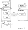
- FIG. 1 is a diagram illustrating a configuration example of a wireless communication system.
- FIG. 2 is a diagram illustrating a configuration example of a wireless communication system including a handover example.
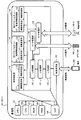
- FIG. 3 is a diagram illustrating a configuration example of a base station.
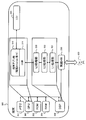
- FIG. 4 is a diagram illustrating a configuration example of the application server.
- FIG. 5 is a diagram illustrating a configuration example of a terminal.
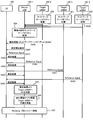
- FIG. 6 is a sequence diagram illustrating an example of an operation for transmitting network capability information.
- FIG. 7 is a sequence diagram illustrating an example of the information collection operation.
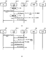
- 8A and 8B are sequence diagrams illustrating an operation example.
- FIG. 9 is a diagram illustrating a configuration example of a packet.
- FIG. 9 is a diagram illustrating a configuration example of a packet.
- FIG. 10 is a diagram illustrating an example of information elements included in the HO Request.
- FIG. 11 is a diagram illustrating an example of information elements included in the HO Request Ack.
- FIG. 12 is a sequence diagram illustrating an overall operation example.
- FIG. 13 is a sequence diagram illustrating an example of the information collection operation.
- FIG. 14 is a diagram illustrating an example of network capability information.
- FIG. 15 is a sequence diagram illustrating an example of an information collecting operation.
- FIG. 16 is a sequence diagram illustrating an operation example when changing the destination.
- FIG. 17 is a sequence diagram illustrating an operation example of prior switching.
- FIG. 18 is a sequence diagram illustrating an example of a server change operation after handover.
- FIG. 19 is a sequence diagram illustrating an example of transmission of application state information.
- FIG. 19 is a sequence diagram illustrating an example of transmission of application state information.
- FIG. 20A is a diagram illustrating a packet configuration example
- FIG. 20B is a diagram illustrating an example of RTCP information.
- FIG. 21 is a flowchart showing an example of the overall operation.
- FIG. 22 is a flowchart showing an example of the overall operation.
- FIG. 23 is a diagram illustrating a configuration example of a wireless communication system.
- FIG. 1 shows a configuration example of a wireless communication system according to the first embodiment.
- the wireless communication system 10 includes eNBs (Evolved Node B) 100-1 and 100-2, MEC (Mobile Edge Computing) servers 200-1 and 200-2, and terminal devices (or UE (User Equipment)). 300-1 and 300-2 and EPC / GW400.
- eNBs Evolved Node B
- MEC Mobile Edge Computing
- terminal devices or UE (User Equipment)
- 300-1 and 300-2 and EPC / GW400 EPC / GW400.
- the eNBs 100-1 and 100-2 perform wireless communication with the terminals 300-1 and 300-2 located in the service available range (or cell range) of the local station and perform various services such as a call service and a web browsing service. It is a base station device or a wireless communication device that provides a simple service. In the following, the eNB may be referred to as a base station, for example.
- the MEC servers 200-1 and 200-1 are, for example, application servers (or application server devices) that realize mobile edge computing.
- the MEC server may be referred to as an application server, for example.
- Application servers 200-1 and 200-1 provide terminals 300-1 and 300-2 with various services such as a Web browsing service and a moving image distribution service via base stations 100-1 and 100-2.
- the application servers 200-1 and 200-2 are disposed near the base stations 100-1 and 100-2, respectively, and are connected to the base stations 100-1 and 100-2, respectively.
- the application servers 200-1 and 200-2 may be arranged (or combined) in the base stations 100-1 and 100-2, for example.
- the application servers 200-1 and 200-2 may be arranged in, for example, an EPC (Evolved Packet Core) network.
- the application servers 200-1 and 200-2 may be arranged in an S-GW (Serving Gateway) or P-GW (PDN (Packet Data Network) Gateway) in the EPC network. It may be connected in the vicinity of the gateway device. All of the above connection forms may be collectively referred to as “application server connected to a base station”, for example.
- the application server 200-1 and the application server 200-2 are connected by a CDN (Content Delivery Network) via the Internet 500 and are connected by a mobile network via the EPC / GW 400.
- the two application servers 200-1 and 200-2 can exchange messages using a CDN or a mobile network.
- the terminals 300-1 and 300-2 are wireless communication devices such as feature phones, smartphones, personal computers, tablet terminals, and game devices, for example.
- the terminal 300-1 is connected to the base station 100-1 to receive service from the application server 200-1
- the terminal 300-2 is connected to the base station 100-2 to connect to the application server.
- An example in which a service is received from 200-2 is shown.
- EPC / GW 400 represents, for example, a gateway device connected to the EPC network.
- Examples of such devices include the S-GW, P-GW, and MME (Mobility Management Entity) described above.
- FIG. 2 shows an example of handover in the wireless communication system 10.
- the radio communication system 10 shown in FIG. 2 is an example including S-GWs 410-1 and 410-2, P-GWs 420-1 and 420-2, and MMEs 430-1 and 430-2 as EPC / GW 400. .
- the terminal 300 When the terminal 300 performs a handover from the base station 100-1 to the base station 100-2, for example, it is a handover between the base stations 100-1 and 100-2 under the same MME 430-1.
- the base stations 100-1 and 100-2 exchange messages (or control information) regarding handover with the other base stations 100-2 and 100-2 using the X2 interface.
- the handover in this case is X2 handover (X2-HO).
- the terminal 300 is handed over from the base station 100-2 under the MME 430-1 to the base station 100-3 under the MME 430-2. ing.
- the base stations 100-2 and 100-3 exchange messages regarding handover via the MMEs 430-1 and 430-2 using the S1 interface.
- the handover in this case is S1 handover.
- the handover destination base station (hereinafter sometimes referred to as “target base station”) to the handover source base station (hereinafter referred to as “source base station”).
- target base station the handover destination base station
- source base station the handover source base station
- the target base station 100-2 is arranged in the application server 200 arranged in the own station and in the S-GW 410-1.
- the control information related to the application server 200 is transmitted.
- the target base station 100-3 when the terminal 300 is handed over from the base station 100-2 to the base station 100-3, the target base station 100-3 includes the application server 200-3 arranged in the own station, and the S-GW 410-2.
- the control information related to the application server placed in is transmitted.
- the target base station 100-4 transmits control information related to the application server arranged in the S-GW 410-2. To do.
- control information related to the application server for example, connection information (or location information) of the application server 200, information related to a route, information related to transmission capability (or transmission delay) of the application server 200, and services that can be provided (or supported). Information, etc.
- connection information or location information
- information related to a route information related to transmission capability (or transmission delay) of the application server 200
- services that can be provided or supported.
- Information etc.
- the control information related to the application server may be referred to as, for example, network capability information. Details will be described later.
- the source base station 100-1 that has received the network capability information at the time of handover can select the application server 200 based on the received network capability information, for example. Details will be described later.
- base stations 100-1 and 100-2 may be referred to as base station 100
- application servers 200-1 and 200-2 may be referred to as application server 200
- terminals 300-1 and 300-2 may be referred to as terminal 300. .
- FIG. 3 is a diagram illustrating a configuration example of the base station 100. Note that the base station 100 illustrated in FIG. 3 represents a configuration example when an application server is connected in the vicinity of the base station 100.
- the base station 100 includes a memory 101, a CPU (Central Processing Unit) 102, a ROM (Read Only Memory) 103, a RAM (Random Access Memory) 104, a DSP (Digital Signal Processing) 105, and a wireless processing unit 160.
- a memory 101 a central processing unit
- CPU Central Processing Unit
- ROM Read Only Memory
- RAM Random Access Memory
- DSP Digital Signal Processing
- the memory 101 stores, for example, various information and data such as network capability information.
- various information, data, or the like is appropriately stored or read out by the CPU 102 or the DSP 105.
- the CPU 102 executes various processes and functions in the base station 100 by, for example, loading a program stored in the ROM 103 into the RAM 104 and executing the loaded program.
- the DSP 105 reads out and executes a program stored in the ROM 103, for example, and thereby executes a terminal control unit 110 and a local application server control information processing unit (hereinafter also referred to as a “local server control information processing unit”) 120.
- the function of the other application server control information processing unit (hereinafter also referred to as “other server control information processing unit”) 130 is executed.
- the DSP 105 executes, for example, the program, so that an S1-IF (Interface) processing unit 140, an X2-IF processing unit 145, an L1 (Layer 1) processing unit 150, an L2 (Layer 2) processing unit 151, The function of the L3 (Layer 3) processing unit 152 is executed.
- S1-IF Interface
- the DSP 105 includes, for example, a terminal control unit 110, a local server control information processing unit 120, another server control information processing unit 130, an S1-IF processing unit 140, an X2-IF processing unit 145, an L1 processing unit 150, an L2 processing unit 151, And the L3 processing unit 152.
- the terminal control unit 110 controls the terminal 300, for example.
- the terminal control unit 110 exchanges user data (or individual data), a message related to handover, and the like with the terminal 300 via the S1-IF processing unit 140, for example. Further, the terminal control unit 110 exchanges user data and the like between the EPC / GW 400 and the other base station 100-2 via the S1-IF processing unit 140 and the X2-IF processing unit 145, for example.
- the terminal control unit 110 includes an information request unit 111 and an information reception unit 112.
- the information request unit 111 transmits, for example, user data or a message to the terminal 300, the EPC / GW 400, or another base station 100-2 via the S1-IF processing unit 140 or the X2-IF processing unit 145. .
- the information receiving unit 112 receives, for example, user data and messages transmitted from the terminal 300, the EPC / GW 400, and the other base station 100-2 via the S1-IF processing unit 140 and the X2-IF processing unit 145. To do. In addition, the information receiving unit 112 receives a message (or control information) related to a handover transmitted from another base station 100-2 or EPC / GW 400, for example.
- the information receiving unit 112 may be, for example, a control information receiving unit.
- the own server control information processing unit 120 processes control information related to the application server 200 connected to the own base station 100, for example.
- the local server control information processing unit 120 generates network capability information or generates a message related to handover.
- the own server control information processing unit 120 includes an information requesting unit 121 and an information receiving unit 122.
- the information request unit 121 transmits, for example, network capability information, a message regarding handover, and the like to the source base station 100-1 via the X2-IF processing unit 145. In addition, the information request unit 121 transmits, for example, network capability information and a message related to handover to the EPC / GW 400 via the S1-IF processing unit 140.
- the information receiving unit 122 may transmit a network capability information transmission request (hereinafter also referred to as a “network capability request”) from the source base station 100-1 via the X2-IF processing unit 145. Receives messages related to handover. In addition, the information receiving unit 122 receives a network capability information transmission request, a message related to a handover, and the like from the EPC / GW 400 via the S1-IF processing unit 140, for example.
- a network capability information transmission request hereinafter also referred to as a “network capability request”
- the information receiving unit 122 receives a network capability information transmission request, a message related to a handover, and the like from the EPC / GW 400 via the S1-IF processing unit 140, for example.
- the other server control information processing unit 130 processes, for example, control information related to the application server 200 connected to another base station.
- the other server control information processing unit 130 generates, for example, a network capability request or a message related to handover.
- the information request unit 131 transmits, for example, a network capability request or a message related to handover to the target base station 100-2 via the X2-IF processing unit 145. In addition, the information request unit 131 transmits a network capability request, a message regarding a handover, and the like to the EPC / GW 400 via the S1-IF processing unit 140, for example.
- the information receiving unit 132 receives network capability information, a message related to handover, and the like from the target base station 100-2 via the X2-IF processing unit 145, for example. Further, the information receiving unit 132 receives network capability information, a message related to handover, and the like from the EPC / GW 400 via the S1-IF processing unit 140, for example.
- the information receiving unit 132 may be a control information receiving unit, for example, because it receives the message (or control information).
- the S1-IF processing unit 140 exchanges packet data related to the S1 interface with the EPC / GW 400. Specifically, for example, the S1-IF processing unit 140 receives user data or a message output from the terminal control unit 110, the local server control information processing unit 120, or the other server control information processing unit 130, and receives them. The packet data is converted into S1 interface packet data and transmitted to the EPC / GW 400. Further, for example, the S1-IF processing unit 140 extracts user data, a message, and the like from the packet data received from the EPC / GW 400, and the terminal control unit 110, the local server control information processing unit 120, or another server control information processing unit To 130.
- the X2-IF processing unit 145 exchanges packet data related to the X2 interface with another base station 100-2. Specifically, the X2-IF processing unit 145 receives, for example, user data and messages output from the terminal control unit 110, the local server control information processing unit 120, or the other server control information processing unit 130, and receives them. The packet data is converted to X2 interface packet data and transmitted to another base station 100-2. Further, for example, the X2-IF processing unit 145 extracts user data, a message, and the like from packet data received from the other base station 100-2, and the terminal control unit 110, the own server control information processing unit 120, or another server Output to the control information processing unit 130.
- the L1 processing unit 150 performs processing related to layer 1 such as modulation processing and encoding processing, for example. Specifically, for example, the L1 processing unit 150 receives a baseband signal from the wireless processing unit 160, performs demodulation processing on the received baseband signal, and generates a MAC (Media Access Control) packet. The L1 processing unit 150 outputs the MAC packet to the L2 processing unit 151. For example, the L1 processing unit 150 receives a MAC packet from the L2 processing unit 151, performs modulation processing on the data included in the received MAC packet, and converts the data into a baseband signal. The L1 processing unit 150 outputs the baseband signal to the wireless processing unit 160.
- MAC Media Access Control
- the L2 processing unit 151 performs processing related to layer 2 such as radio resource allocation and retransmission control, for example. Specifically, for example, the L2 processing unit 151 extracts an IP (Internet protocol) packet from the MAC packet received from the L1 processing unit 150, and outputs the extracted IP packet to the L3 processing unit 152. The L2 processing unit 151 generates a MAC packet by adding a MAC header or the like to the IP packet received from the L3 processing unit 152, for example, and outputs the generated MAC packet to the L2 processing unit 151. .
- IP Internet protocol
- the L3 processing unit 152 performs processing related to layer 3, such as broadcast information distribution processing and RRC (Radio Resource Control) connection. Specifically, for example, the L3 processing unit 152 outputs the IP packet received from the L2 processing unit 151 to the terminal control unit 110 via the S1-IF processing unit 140. Also, the L3 processing unit 152 outputs the IP packet received from the terminal control unit 110 via the S1-IF processing unit 140 to the L2 processing unit 151, for example.
- RRC Radio Resource Control
- the radio processing unit 160 performs, for example, frequency conversion processing on the baseband signal output from the L1 processing unit 150, converts the baseband signal into a radio signal in the radio band, and transmits the radio signal to the terminal 300.
- the radio processing unit 160 receives a radio signal transmitted from the terminal 300, performs frequency conversion processing on the received radio signal, converts the radio signal into a baseband signal of the baseband band, and converts the converted baseband signal The signal is output to the L1 processing unit 150.
- FIG. 4 is a diagram illustrating a configuration example of the application server 200.
- the application server 200 includes a CPU 201, a ROM 202, a RAM 203, and a memory 204.
- the CPU 201 can execute the functions of the data transmission / reception unit 210, the data analysis unit 220, and the application unit 230 by reading a program stored in the ROM 202, loading it into the RAM 203, and executing the loaded program. is there.
- the CPU 201 corresponds to the data transmission / reception unit 210, the data analysis unit 220, and the application unit 230.
- the data transmission / reception unit 210 transmits or receives data, control information, or the like between the base station 100 and the EPC / GW 400, for example.
- the data transmission / reception unit 210 may transmit / receive data, control information, and the like using an S1 interface (or S1-U (User plane)).
- the data analysis unit 220 analyzes control information and exchanges (or relays) user data between the data transmission / reception unit 210 and the application unit 230, for example.
- the data analysis unit 220 can instruct the application unit 230 to provide a service or instruct to stop based on the control information.
- the application unit 230 provides a service to the terminal 300 or stops providing the service in accordance with an instruction from the data analysis unit 220, for example.
- the application unit 230 provides the moving image distribution service by reading out the content stored in the memory 204 and transmitting the content to the terminal 300.
- the data transmission / reception unit 210 or the data analysis unit 220 may be a communication unit that transmits / receives user data (or individual data) to / from the terminal 300 via the base station 100, for example.
- the data transmission / reception unit 210 or the data analysis unit 220 transfers to, for example, the application server 200-2 connected to the target base station 100-2 or the application server 200-1 connected to the source base station 100-1.
- a server line control unit that transmits application status information may be used.
- FIG. 5 is a diagram illustrating a configuration example of the terminal 300.
- the terminal 300 includes a memory 301, a CPU 302, a ROM 303, a RAM 304, a DSP 305, an LCD (Liquid Crystal Display) 320, and a wireless HW (Hardware) 330.
- the memory 301 stores, for example, user data and control information.
- the CPU 302 reads the program stored in the ROM 303, loads it into the RAM 304, and executes the loaded program to execute the function of the terminal application unit 310.
- the CPU 302 corresponds to the terminal application unit 310, for example.
- the terminal application unit 310 executes various applications such as telephone and web browsing via an OS (Operating System) unit 311, for example.
- OS Operating System
- the LCD 320 receives, for example, user data from the terminal application unit 310 and displays the data as a video. Further, the LCD 320 generates control information corresponding to the operation and outputs it to the terminal application unit 310, for example, by an operation by the user. Examples of such control information include a content distribution request.
- the DSP 305 executes the functions of the L1 processing unit 331, the L2 processing unit 332, and the L3 processing unit 333 by executing a program stored in the ROM 303 in accordance with an instruction from the CPU 302.
- the DSP 305 corresponds to, for example, the L1 processing unit 331, the L2 processing unit 332, and the L3 processing unit 333.
- the wireless HW 330 performs processing on a wireless signal, for example.
- the wireless HW 330 receives a baseband signal from the L1 processing unit 331, performs frequency conversion processing on the baseband signal, converts the baseband signal into a wireless signal, and transmits the converted wireless signal to the base station 100.
- the wireless HW 330 receives, for example, a wireless signal transmitted from the base station 100, performs frequency conversion processing on the received wireless signal, converts it to a baseband signal, and performs an L1 process on the converted baseband signal.
- the wireless HW 330 may be a receiving unit that receives control information, user data, and the like transmitted from the base station 100, for example.
- the L1 processing unit 331 performs processing related to layer 1 such as modulation processing and encoding processing, for example. Specifically, for example, the L1 processing unit 331 performs a demodulation process or the like on the baseband signal received from the wireless HW 330 to generate a MAC packet, and outputs the generated MAC packet to the L2 processing unit 332. In addition, the L1 processing unit 331 performs modulation processing on the data included in the MAC packet received from the L2 processing unit 332 and converts the data into a baseband signal, and outputs the converted baseband signal to the wireless HW 330, for example. To do.
- the L2 processing unit 332 performs processing related to layer 2 such as retransmission control, for example. Specifically, for example, the L2 processing unit 332 receives a MAC packet from the L1 processing unit 331, extracts an IP packet from the MAC packet, and outputs the extracted IP packet to the L3 processing unit 333. Also, the L2 processing unit 332 receives an IP packet from the L3 processing unit 333, generates a MAC packet by adding a MAC header from the IP packet, and outputs the generated MAC packet to the L1 processing unit 331, for example.
- the L3 processing unit 333 performs processing related to layer 3, such as broadcast information distribution processing and RRC (Radio Resource Control) connection. Specifically, the L3 processing unit 333 outputs the IP packet received from the L2 processing unit 332 to the terminal application unit 310, for example. Further, the L3 processing unit 333 outputs, for example, the IP packet received from the terminal application unit 310 to the L2 processing unit 332.
- layer 3 such as broadcast information distribution processing and RRC (Radio Resource Control) connection.
- RRC Radio Resource Control
- FIG. 6 is a sequence diagram illustrating an example of the first operation example.
- the source base station 100-1 transmits a network capability request to the target base station 100-2 (S10).
- the target base station 100-2 transmits a network capability response to the source base station 100-1.
- the source base station 100-1 requests transmission of network capability information of the application server 200-2 connected to the target base station 100-2. Then, the target base station 100-2 transmits network capability information to the source base station 100-1 by a network capability response. Details of the operation example 1 will be described later.
- FIG. 7 is a sequence diagram illustrating the second operation example. This operation example 2 is an example of information collection operation.
- the target base stations 100-2 to 100-4 each collect network capability information of the application server 200 connected to the own station (S20 to S22).
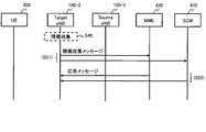
- FIG. 13 shows an example of network capability information collection operation.
- the target base station 100-2 transmits an information collection message to the EPC / GW 400 (in FIG. 13, MME 430 and S-GW 410), and receives a response message from the EPC / GW 400 (S52).
- the target base station 100-2 performs the following processing. That is, the local server control information processing unit 120 generates an information collection message and transmits it to the EPC / GW 400 connected to the local station via the S1-IF processing unit 140 or the like.
- the own server control information processing unit 120 receives a response message from the EPC / GW 400 via the S1-IF processing unit 140 and extracts network capability information from the response message.
- the extracted network capability information is stored in the memory 101.
- the own server control information processing unit 120 transmits and receives each message via the information requesting unit 121 and the information receiving unit 122.
- the local server control information processing unit 120 may be a control information collecting unit that collects control information such as network capability information.
- the local server control information processing unit 120 uses an API (Application Programming Interface) or the like to store the application stored in the memory 101
- the network capability information of the server 200-2 is read out.
- the target base station 100-2 can acquire the network capability information of the application server 200-2 that is combined with the target base station 100-2.
- each of the target base stations 100-2 to 100-4 transmits the collected network capability information to the source base station 100-1 that is the base station of the handover source (S23).
- the own server control information processing unit 120 of each of the target base stations 100-2 to 100-4 transmits the collected network capability information to the source base station 100-1 via the X2-IF processing unit 145.
- the source base station 100-1 receives the network capability information transmitted from the target base stations 100-2 to 100-4, and acquires the network capability information of the adjacent target base stations 100-2 to 100-4. (S24).
- the other server control information processing unit 130 of the source base station 100-1 receives the network capability information via the S1-IF processing unit 140, and stores the received network capability information in the memory 101.
- the source base station 100-1 can collect the network capability information of the target base stations 100-2 to 100-4 in advance before the handover is started.
- the other server control information processing unit 130 in the source base station 100-1 can also be a control information collecting unit, for example.
- the source base station 100-1 transmits broadcast information including the collected network capability information to the terminal 300 (S25).
- the source base station 100-1 performs the following processing. That is, the own server control information processing unit 120 outputs the collected network capability information to the terminal control unit 110.
- the terminal control unit 110 generates broadcast information including network capability information and transmits it to the terminal 300.
- the source base station 100-1 transmits a measurement start request to the terminal 300 (S26), and the terminal 300 receives based on the reference signals transmitted from the base stations 100-1 to 100-4.
- the power is measured (S27, S29, S31, S33), and the measurement result is transmitted to the source base station 100-1 (S28, S30, S32, S34).
- the source base station 100-1 determines the target base station 100-2 as a handover destination based on the measurement result (S35), and transmits application state information to the target base station 100-2 (S36).
- Application state information is information regarding the continuation or state of services provided from the application server 200 in the terminal 300, for example. As an example of such information, for example, there is a time when the application server 200 provides a service to the terminal 300. Details of the application status information will be described later.
- the terminal 300 thereafter performs a handover procedure (S37).
- the information collection operation is performed before the handover is started.
- Such information collection operation (S20 to S24) may be performed at least once before the start of handover, for example.
- an information collection operation (S20 to S24) may be performed at regular intervals.
- FIG. 15 shows a sequence example when it is performed after the reference signal is transmitted as an example of the information collecting operation.
- the terminal 300 receives the reference signals from the base stations 100-1 to 100-4 (S62). , S64, S66, S68). Then, the terminal 300 transmits the measurement result to the source base station 100-1 (S63, S65, S67, S69).
- each of the target base stations 100-2 to 100-4 collects network capability information of the application server 200 connected to the own base station (S70 to S72). Similarly to the example of FIG. 7, each of the target base stations 100-2 to 100-4 may collect using the S1 interface, API, or the like.
- each target base station 100-2 to 100-4 collects network capability information (S80 to S82).
- Each of the target base stations 100-2 to 100-4 can collect the latest network capability information, for example, by performing collection at regular intervals. Then, each target base station 100-2 to 100-4 transmits the collected network capability information to the source base station 100-1.
- the own server control information processing unit 120 of the source base station 100-1 is, for example, a control information collecting unit that periodically collects control information.
- each of the target base stations 100-2 to 100-4 collects network capability information by transmitting an information collection message (S51) and receiving a response message (S52), for example, as shown in FIG. May be.
- the terminal 300 continuously transmits the measurement result to the source base station 100-1 (S83).
- Network capability request how network capability information and its request (hereinafter may be referred to as “network capability request”) is transferred from the target base station 100-2 to the source base station 100-1 will be described.
- network capability request There are two examples:
- network capability information and its request are added to a message defined as a HO procedure in 3GPP or the like.
- FIG. 8A is a diagram showing a sequence example in such a case.
- the terminal 300 transmits a Measurement Report to the source base station 100-1 (S41).
- the source base station 100-1 transmits a HO (Handover) Request including a request for network capability information (hereinafter sometimes referred to as a “network capability request”) to the target base station 100-2. (S42).
- HO Home
- network capability request a request for network capability information
- the target base station 100-2 transmits a HO Request Ack (Acknowledgement) including network capability information related to the application server connected to the own station to the source base station 100-1 (S44).
- a HO Request Ack Acknowledgement
- the source base station 100-1 transmits a HO Command to the terminal 300 (S45).
- the source base station 100-1 may determine the application server 200 connected to the target base station 100-2, which is the takeover destination of the application server 200, based on the network capability information.
- the HO Command includes, for example, information on the target base station 100-2.
- the terminal 300 receives control information for connecting to the target base station 100-2 by receiving the HO Command.
- the target base station 100-2 may collect the network capability information related to the application server 200 connected to the own station in advance before the handover sequence is performed (S40) or receive a HO Request. May be collected (S43).
- the target base station 100-2 may acquire the network capability information by performing the process shown in FIG. That is, the target base station 100-2 transmits an information collection message to the MME 430 or S-GW 410 under its control (S51), and receives a response message from the MME 430 or S-GW 410 (S52).
- network capability information may be transferred using an API in the target base station 100-2.
- the second example is an example of adding network capability information and a network capability request as a new sequence in handover.
- FIG. 8B is a diagram showing a sequence example in such a case.
- the source base station 100-1 transmits a HO Request to the target base station 100-2 (S46), and then a new message (or a new procedure) indicating a request for network capability information. (S47).
- the target base station 100-2 Upon receiving this message, the target base station 100-2 transmits a response message (new procedure) including network capability information to the source base station 100-1 (S48).
- the target base station 100-2 transmits a HO Request Ack to the source base station 100-1 (S49), and the source base station 100-1 transmits a HO Command to the terminal 300 (S45).
- the network capability request (S47) and the network capability response (S48) are transmitted between the HO Request (S46) and the HO Request Ack (S49) in the example of FIG. 8B, but the handover is completed. It may be transmitted in the meantime.
- the base station 100 is the source base station 100-1 and a handover is performed in the terminal 300, for example, the following operation is performed.
- control information (such as Measurement Report) (or message) transmitted from the terminal 300 is transmitted to the terminal control unit 110 via the wireless processing unit 160 or the like.
- the terminal control unit 110 instructs the local server control information processing unit 120 and the other server control information processing unit 130 to transmit control information related to handover.
- the terminal control unit 110 may instruct the other server control information processing unit 130 to transmit a network capability request, and may instruct the own server control information processing unit 120 for other control information.
- the local server control information processing unit 120 and the other server control information processing unit 130 generate control information related to handover according to the instruction, and the target base station via the X2-IF processing unit 145 and the S1-IF processing unit 140 100-2 and EPC / GW 400 are respectively transmitted.
- the other server control information processing unit 130 may generate and transmit a HO Request including a network capability request, or may generate and transmit a network capability request as a new procedure.
- control information transmitted from another base station 100-2 or EPC / GW 400 is transmitted to the own server control information processing unit 120 or other server via the X2-IF processing unit 145 or S1-IF processing unit 140, respectively. It is transmitted to the control information processing unit 130.
- the network capability information (which may be included in the HO Request Ack or may be a new procedure) is stored in the other server control information processing unit 130, and other control information related to handover is stored in the own server control information processing unit 120. You may receive it.
- the own server control information processing unit 120 and the other server control information processing unit 130 output the received control information and the like to the terminal control unit 110.
- the terminal control unit 110 transmits the received control information and the like to the terminal 300 via the S1-IF processing unit 140, the X2-IF processing unit 145, and the like.
- the base station 100 is the target base station 100-2 and a handover is performed in the terminal 300, for example, the following operation is performed.
- control information transmitted from the source base station 100-1 and the EPC / GW 400 is transmitted to the own server control information processing unit 120 and other server control via the X2-IF processing unit 145 and the S1-IF processing unit 140, respectively. It is transmitted to the information processing unit 130.
- the own server control information processing unit 120 may receive a network capability request, control information related to other handover, and the like.
- the local server control information processing unit 120 Upon receiving a network capability request (which may be included in the HO Request or may be a new procedure), the local server control information processing unit 120 exchanges a message with the EPC / GW 400 via the S1-IF processing unit 140. To collect network capability information.
- the local server control information processing unit 120 reads the network capability information stored in the memory 101 from the memory 101.
- the own server control information processing unit 120 transmits the collected or read network capability information to the source base station 100-1 via the X2-IF processing unit 145.
- the local server control information processing unit 120 may generate HO Request Ack including network capability information, or may generate network capability information as a new procedure.
- the server control information processing unit 120 receives other control information related to handover, the server control information processing unit 120 generates control information related to handover, etc., and sends the EPC via the S1-IF processing unit 140 and the X2-IF processing unit 145. / GW 400 and source base station 100-1.
- the terminal control unit 110, the own server control information processing unit 120, and the other server control information processing unit 130 receive control information and the like via the information receiving units 112, 122, and 132, and receive the information request unit 111, Control information and the like are transmitted via 121 and 131.
- the local server control information processing unit 120 and the other server control information processing unit 130 may be control information requesting units that request control information.
- the terminal control unit 110 may be a transmission unit that transmits control information related to handover to the terminal 300.
- the own server control information processing unit 120 may be a control information notification unit.
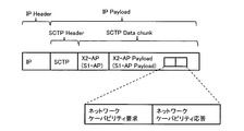
- FIG. 9 is a diagram illustrating a configuration example of packet data by the X2 interface.
- the payload area of the IP packet includes an SCTP (Stream Control Transmission Protocol) header and an SCTP data chunk area.
- the SCTP data chunk area includes an X2-AP (X2 Application Protocol) header and an X2-AP payload area, and the X2-AP payload area includes a network capability request and network capability information.
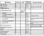
- FIG. 10 is a diagram illustrating an example of an information element (IE (Information Element)) included in the HO Request.
- IE Information Element
- FIG. 10 illustrates an example of an information element (IE (Information Element)) included in the HO Request.
- IE Information Element
- FIG. 9 When the packet shown in FIG. 9 is transmitted as a HO Request, an information element of HO Requestno is included in the X2-AP payload area.
- NW Capability Request Condition is added as a new information element to the HO Request as shown in FIG.
- NW Capability Request Condition represents, for example, a network capability request.
- the HO Request information element including “NW Capability Request Condition” is generated by the other server control information processing unit 130 of the source base station 100-1.
- the other server control information processing unit 130 transmits the generated HO Request to the target base station 100-2 via the information request unit 131 and the X2-IF processing unit 145.
- FIG. 11 is a diagram illustrating an example of information elements included in the HO Request Ack.
- the information element of HO Request Ack is included in the X2-AP payload area.
- NW Capability is added as a new information element to the HO Request Ack as shown in FIG. “NW Capability”, for example, represents network capability information.
- FIGS. 10 and 11 are examples in which the network capability request and the network capability information are included in the HO Request and the HO Request Ack, respectively.
- the network capability request and the network capability information may be transmitted by being included in another message exchanged between the base stations 100-1 and 100-2 in the handover procedure. In either case, as shown in FIGS. 10 and 11, it is possible to exchange these pieces of information by adding new information elements.
- a new procedure may be used that includes “Message type” and “NW Capability Request Condition” as information elements.
- information including “Message type” and “NW Capability” as information elements among the information elements shown in FIG. 11 may be used as a new procedure.
- FIG. 12 shows an example of information elements included in the broadcast information when network capability information is transmitted as broadcast information.
- the broadcast information is transmitted, for example, included in SIB (System Information Block).
- SIBs currently exist from SIB1 to SIB25.
- the example shown in FIG. 12 represents an example of information elements in the case of SIB2.
- “NW Capability” is included as a new information element in SIB2
- the network capability information of target base station 100-2 is included and transmitted in “NW Capability”.
- FIG. 12 is an example, and network capability information may be transmitted using other SIBs such as SIB1, SIB3 to SIB25. In this case, a new information element is added as shown in FIG. Will be.
- FIG. 14 shows an example of network capability information.
- the network capability information includes, for example, information on destination candidates, connection information, route information, transmission delay information, and corresponding services.
- the destination candidate represents, for example, the application server 200 connected to the target base station 100-2.
- “application server A” is an application server arranged in the base station 100-2, “application server B”. "Is an application server arranged in the S-GW 410-1.
- connection information represents, for example, identification information that identifies the application server 200 from other application servers.
- the connection information is represented by an IP address.
- the connection information is used, for example, when specifying an address to which application state information is transferred from the application server 200.
- the route information represents, for example, where the handover destination application server 200 is located in the network.
- the path information is “(P-GW 420-1)-(S-GW 410-1)-(base station 100-2) ".
- path information is represented by connecting nodes from the P-GW 420 to the application server 200 under the application server 200.
- the transmission delay information represents, for example, the time taken to provide the service on the transmission path from the application server 200 to the terminal 300.
- “10 ms” indicates that it takes “10 ms” for the data to be transmitted from the application server A and received by the terminal 300.
- the transmission delay information is used, for example, as to whether or not the transmission delay requirement is satisfied when the service provided by the application server 200 is continued.
- Corresponding service represents, for example, the quality of service to be provided and the content of the service.
- “video distribution A” and “video distribution B” represent video distribution services of the same content
- “video distribution A” represents high image quality
- “video beach B” represents low image quality.
- “moving image distribution C” represents, for example, a moving image distribution service of content different from “moving image distribution A”.
- the corresponding service may be used, for example, to confirm whether or not the service provided by the handover destination application server 200 corresponds to the service provided by the handover source application server 200.
- the corresponding service may include, for example, an acceptable transmission delay time when each service is provided in the application server 200.
- the transmission delay time may be included for each service, such as “10 ms” for the allowable transmission delay time for “video distribution A” and “15 ms” for the allowable transmission delay time for “video distribution B”.
- connection information” and “route information” represent position information of the application server 200
- transmission delay information represents information regarding the transmission capability of the application server 200
- corresponding service can be provided. Represents a service.
- the network capability information including such information is included in the information element “NW Capability” shown in FIG. 11, for example, and transmitted from the target base station 100-2 to the source base station 100-1.
- FIG. 16 shows a sequence example of this operation example.
- the source base station 100-1 selects the target base station 100-2 based on the Measurement Report (S41) received from the terminal 300, and transmits a HO Request to the selected target base station 100-2 (S42). Then, the source base station 100-1 transmits a HO Request including a network capability request.
- the source base station 100-1 receives the HO Request Ack including the network capability information (S44). At this time, the source base station 100-1 changes the handover destination from the base station 100-2 to the base station 100-3 based on the network capability information (S90).
- the other server control information processing unit 130 of the source base station 100-1 receives the network capability information from the target base station 100-2, and outputs the received network capability information to the terminal control unit 110.
- the terminal control unit 110 changes the target base station 100-2 based on the network capability information.
- the terminal control unit 110 transmits the “transmission delay time” and “corresponding service” of the source application server 200-1 and the “transmission delay time” and “correspondence” of the application server 200-2 or 200-3. The determination may be made based on whether or not “service” matches.
- the terminal control unit 110 determines that the capability information requested by the source application server 200-1 matches the destination application server 200-3, the terminal control unit 110- connects to the base station 100- connected to the application server 200-3. 3 is changed to the handover destination mobile station.
- the terminal control unit 110 may be radio channel control that changes the target base station from the base station 100-2 to the base station 100-3, for example.
- the source base station 100-1 transmits a HO Request to the changed base station 100-3 (S91), and receives a HO Request Ack from the base station 100-3 (S92).
- the source base station 100-1 may not include the network capability request in the HO Request
- the target base station 100-2 may not include the network capability information in the HO Request Ack.
- the terminal control unit 110 of the source base station 100-1 generates a HO Request, and transmits the generated HO Request to the changed target base station 100-3 via the X2-IF processing unit 145.
- the source base station 100-1 transmits a HO Command including information designating that the destination is the base station 100-3 to the terminal 300 (S93), with the base station 100-3 as the target base station.
- the handover procedure is continued (S94).
- Advance switching> This operation example is described in ⁇ 3.
- the application server 200 (or the target base station 100-2) is switched in advance based on the network capability information collected in advance by the source base station 100-1, although it partially overlaps with the selection of other target base station>. is there.
- the communication switching between the terminal 300 and the target base station 100-2 is completed after the handover procedure is completed, the communication between the terminal 300 and the application server 200 can be resumed.
- FIG. 17 shows a sequence example in this operation example. It is assumed that the network capability of the application server 200-2 has already been collected from the target base station 100-2 in the source base station 100-1.
- the terminal 300 receives provision of service from the application server 200-1 (S100), and transmits a Measurement Report to the source base station 100-1 (S101).
- the source base station 100-1 determines the start of handover based on the measurement result (S102), and determines the application server 200-2 as the switching destination based on the network capability information collected in advance (S103). For example, the own server control information processing unit 120 of the source base station 100-1 changes the switching destination of the application server 200 from the application server 200-1 to the application server 200-2 based on the network capability information read from the memory 101. Decide to change.
- the own server control information processing unit 120 may be, for example, a line control unit that determines a switching destination of the application server 200.
- the source base station 100-1 starts handover (S105), and exchanges HO Request and HO Request Ack with the target base station 100-2 having the application server 200-2 (S106, S107). .
- the source base station 100-1 transmits a HO Command including information specifying the base station 100-2 as a handover destination to the terminal 300 (S108), and continues the handover procedure (S109).
- the terminal 300 receives a service from the application server 200-2 (S110).
- the source base station 100-1 may make such a determination, or the application server 200-1 before switching may be the switching destination application server 200-2.
- a switching message may be transmitted to In the latter case, for example, the following processing is performed.
- the terminal control unit 110 of the source base station 100-1 reads the network capability information stored in the memory 101 when receiving the Measurement Report. Then, the terminal control unit 110 transmits the generated switching instruction to the application server 200-1 via the S1-IF processing unit 140.
- the data analyzing unit 220 of the application server 200-1 receives the switching instruction via the data transmitting / receiving unit 210
- the data analyzing unit 220 generates a switching message to the switching destination application server 200-2 based on the switching instruction.
- the data analysis unit 220 transmits a switching message to the application server 200-2 via the data transmission / reception unit 210.
- the data analysis unit 220 of the application server 200-2 prepares to start providing services to the terminal 300 based on the received switching message.
- FIG. 18 shows a sequence example of this operation example.
- the source base station 100-1 determines the start of handover (S102) and determines the destination of the application server 200 (S103). In this case, the source base station 100-1 may determine the target base station 100-2 based on network capability information collected in advance as in the above example.
- the example of FIG. 18 represents an example in which the source base station 100-1 determines a handover destination without performing prior collection.
- the source base station 100-1 when the source base station 100-1 starts a handover (S105), the source base station 100-1 transmits a HO Request including a network capability request to the target base station 100-2 (S120).
- the source base station 100-1 receives the HO Request Ack including the network capability information from the target base station 100-2 (S121), and transmits it to the HO Command and the terminal 300 (S122).
- the source base station 100-1 switches the connection of the application server 200-1 to the application server 200-2 (S123), and continues the handover procedure (S124).
- the target base station 100-2 determines to change the connection destination from the application server 200-2 to the application server 200-3 based on the network capability information (S125).
- the own server control information processing unit 120 of the target base station 100-2 changes the connection destination of the application server 200 based on the network capability information stored in the memory 101. Specifically, the own server control information processing unit 120 compares the network capability information of the application server 200-1 with the network capability information of the application server 200-2. In addition, the own server control information processing unit 120 compares the network capability information of the application server 200-1 with the network capability information of the application server 200-2. If the own server control information processing unit 120 determines that the condition of the latter is better than that of the former, the own server control information processing unit 120 changes the application server 200-3.
- the own server control information processing unit 120 may be, for example, a line control unit that changes an application server.
- the target base station 100-2 transmits a switching instruction to the switching source application server 200-2 (S126).
- the following processing is performed. That is, when the terminal control unit 110 of the target base station 100-2 receives the notification of the change of the connection server from the own server control information processing unit 120, it generates a switching instruction.
- the terminal control unit 110 transmits a switching instruction to the application server 200-2.
- the data analysis unit 220 of the application server 200-2 receives the switching instruction and interrupts the provision of service to the terminal 300. Then, the data analysis unit 220 transmits a switching instruction to the switching destination application server 200-3 via the data transmission / reception unit 210.
- the data analysis unit 220 of the application server 200-3 receives the switching instruction via the data transmission / reception unit 210, determines to start providing the service to the terminal 300, and notifies the application unit 230 of it.
- the application unit 230 starts providing a service to the terminal 300 in accordance with a notification from the data analysis unit 220.
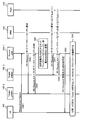
- FIG. 19 shows a sequence example of this operation example.
- the source base station 100-1 transmits application state information to the target base station 100-2.
- the application status information it may be transmitted using the HO Request (S141), as in FIGS. 8A and 8B, or may be transmitted as a new procedure (S142). .
- FIG. 20A shows an example of a packet configuration based on RTP (Real-time Transfer Protocol) protocol
- FIG. 20B shows an example of RTCP information transmitted by RTCP (Real-time Transport Control Protocol).
- RTCP information is encapsulated in the payload area of the RTP packet, and further content data and the like are inserted and transmitted to the transmission destination.
- the application server 200 may receive a RTP packet transmitted from another server device connected via the CDN using the CDN, and perform streaming distribution using the RTP (for example, FIG. 1). ).
- the application server 200 can extract RTCP information from the RTP packet received via the CDN.
- the RTCP information includes, for example, the data amount of the stream transmitted to the application server 200 such as SR (Sender Report) and the transmission time (or distribution time) related to the transmitted stream. Therefore, the application server 200 can extract the data amount and delivery time of the service delivered to the terminal 300 from the RTCP information from the RTP packet.
- the following processing may be performed. That is, when the data analysis unit 220 of the application server 200-1 connected to the source base station 100-1 receives the RTP packet via the data transmission / reception unit 210 and the CDN, it extracts the SR information of the RTCP information. Then, the data analysis unit 220 transmits the extracted RS information to the source base station 100-1 via the data transmission / reception unit 210.
- the own server control information processing unit 120 of the source base station 100-1 When receiving the SR information, the own server control information processing unit 120 of the source base station 100-1 generates application state information including the SR information.
- the own server control information processing unit 120 generates a HO Request including the application state information or a new procedure including the application state information, and transmits it to the target base station 100-2.
- an information element related to the application state information may be added to the information element of the HO Request.
- such an information element may be added after “NW Capability Request Condition”.
- the source base station 100-1 transmits the application state information to the target base station 100-2 (S141 or S142), the source base station 100-1 receives the HO Request Ack from the target base station 100-2 (S143), and receives the HO Command. It transmits to the terminal 300 (S144).
- the source base station 100-1 may generate an HO Request including application status information and a network capability request, and transmit the HO Request to the target base station 100-2 (S141, S142). Further, the source base station 100-1 may generate and transmit a new procedure including application state information and a network capability request.
- 21 and 22 are flowcharts showing an example of the entire operation. Since the part already described is also included, it may be briefly described.
- the source base station 100-1 When the source base station 100-1 starts processing, it determines whether to perform handover (S150). For example, the terminal control unit 110 of the source base station 100-1 determines the execution of the handover based on the information included in the received Measurement Report. Here, the terminal control unit 110 will be described below as determining that the handover is to be executed.
- the source base station 100-1 transmits a network capability request to the target base station 100-2 (S151).
- the network capability request may be included in the HO Request, or may be transmitted by a new procedure (for example, FIG. 8A and FIG. 8B).
- the target base station 100-2 starts processing and receives a network capability request from the source base station 100-1 (S152).
- the target base station 100-2 creates network capability information (S153), and transmits the created network capability information to the source base station 100-1 (S154). Then, the target base station 100-2 waits for reception of a handover request (S154).
- the source base station 100-1 determines whether there is network capability information that matches the conditions of the source application server 200-1 (S156).
- the other server control information processing unit 130 of the source base station 100-1 outputs the received network capability information to the own server control information processing unit 120 when receiving the network capability information.
- the own server control information processing unit 120 reads the network capability information of the application server 200-1 connected to the source base station 100-1 from the memory 101.
- the own server control information processing unit 120 compares and determines the network capability information of the own application server 200-1 and the network capability information received from the target base station 100-2. As a comparison method, for example, whether the former network capability information matches the latter network capability information, or whether the latter network capability information satisfies the former network capability information, etc. It may be done.
- the source base station 100-1 determines a destination server (S157) when there is network capability information that matches the conditions (when “conditions match” in S156).
- the following processing is performed. That is, if there is network capability information that matches the network capability information of the application server 200-1, the other server control information processing unit 130 determines the application server 200-2 having the network capability information as the destination server. To do.
- the source base station 100-1 operates when the application server 200-1 connected to the source base station 100-1 does not have the network capability information that matches the conditions (“condition does not match” in S156). Is stopped (S158).
- the own server control information processing unit 120 determines to stop the application server 200-1 when there is no network capability information that matches the network capability information of the application server 200-1.
- the own server control information processing unit 120 transmits a stop command to the application server 200-1.
- the data analysis unit 220 of the application server 200-1 instructs the application unit 230 to stop providing the service to the terminal 300, and the application unit 230 stops providing the service according to the instruction. .
- the source base station 100-1 then ends a series of processing (S159).
- the source base station 100-1 determines the destination server (S157), it determines the transmission method of the application status information (S160).
- the source base station 100-1 determines how to transmit the application state information. For example, the source base station 100-1 determines “CDN present” when the CDN is connected in the application server 200-1, and determines “no CDN” when the CDN is not connected.
- the local server control information processing unit 120 may read and determine information regarding the presence / absence of the CDN connection of the application server 200 stored in the memory 101.
- the source base station 100-1 selects the CDN when the CDN is connected to the application server 200-1 (“with CDN” in S160) (S161). On the other hand, when the CDN is not connected (“No CDN” in S162)), the source base station 100-1 selects a mobile network (S162). For example, the local server control information processing unit 120 determines selection.
- the source base station 100-1 instructs the transfer start of the application state information and starts handover (S163).
- the own server control information processing unit 120 generates a transfer start instruction indicating whether to transmit via the CDN or the mobile network, and transmits it to the application server 200-1.
- the local server control information processing unit 120 instructs the terminal control unit 110 to start handover.
- the application server 200-1 transmits the application status information to the destination application server 200-2 (S165 in FIG. 22).
- the data analysis unit 220 of the application server 200-1 extracts the data amount and delivery time transmitted from the RTP packet to the terminal 300, and obtains application state information including the data amount and delivery time. Generate. Then, the data analysis unit 220 transmits the application status information to the transfer destination (here, the application server 200-2) included in the transfer start instruction.
- the destination application server 200-2 receives the application status information (S166).
- the data analysis unit 220 of the application server 200-2 receives the application state information via the data transmission / reception unit 210.
- the application server 200-2 prepares for the service provision start for the terminal 300 (S167).
- the following processing is performed. That is, when receiving the application state information, the data analysis unit 220 of the application server 200-2 instructs the application unit 230 to start preparation.
- the application unit 230 reads and prepares user data related to the service stored in the memory 204.
- the application server 200-2 transmits an operation preparation completion to the application server 200-1 (S168).
- the following processing is performed. That is, when the application unit 230 finishes reading the user data addressed to the terminal 300 from the memory 204, the application unit 230 notifies the data analysis unit 220 of the fact, and the data analysis unit 220 receives the notification and determines that the operation preparation is complete. Then, the data analysis unit 220 notifies the application server 200-1 of the completion of operation preparation via the data transmission / reception unit 210.
- the application server 200-1 Upon receiving the operation preparation completion (S169), the application server 200-1 stops providing the service to the terminal 300 (S170). Then, the application server 200-1 ends the series of processes (S171).
- the following processing is performed. That is, when the data analysis unit 220 of the application server 200-1 receives the completion of the operation preparation, it instructs the application unit 230 to stop providing the service to the terminal 300. In response to the instruction, the application unit 230 stops the service.
- the source base station 100-1 and the target base station 100-2 execute a handover procedure (S172).
- the source base station 100-1 ends a series of processing (S173).
- the target base station 100-2 notifies the application server 200-2 of a handover completion notification or a data communication preparation completion (S174).
- the following processing is performed. That is, when the terminal control unit 110 of the target base station 100-2 completes the handover procedure, the terminal control unit 110 notifies the server control information processing unit 120 to that effect.
- the server control information processing unit 120 generates a message indicating handover completion notification or data communication preparation completion, and transmits the message to the application server 200-2.
- Application server 200-2 receives the notification of handover completion or data communication preparation completion, and starts providing services to terminal 300 (S176). Then, the application server 200-2 ends the series of processes (S177).
- the following processing is performed. That is, when the data analysis unit 220 of the application server 200-2 receives a message indicating completion of handover or preparation for data communication, the data analysis unit 220 instructs the application unit 230 to start providing a service to the terminal 300. In response to the instruction, the application unit 230 starts providing services to the terminal 300.
- the target base station 100-2 transmits network capability information to the source base station 100-1 (S154 in FIG. 21). Accordingly, the source base station 100-1 can also select the destination application server 200-2 based on the network capability information (eg, “location information”) (FIG. 17). Further, the target base station 100-2 can also change the application server 200-3 after the handover based on the network capability information. Since the source base station 100-1 and the target base station 100-2 select the application servers 200-2 and 200-3 based on the network capability information, the service distributed from the source application server 200-1 Can be continued. Specifically, for example, the application server 200-2 or 200-3 having network capability information that matches the “transmission delay” or “corresponding service” of the application server 200-1 is selected, so that service continuity is achieved. Is possible.
- the application server 200-2 or 200-3 having network capability information that matches the “transmission delay” or “corresponding service” of the application server 200-1 is selected, so that service continuity is achieved. Is possible.
- transmission of network capability information is performed, for example, between Measurement Report and HO Command (for example, FIG. 8A and FIG. 8B). Therefore, it is possible to transmit the network capability information earlier than when the network capability information is transmitted after the handover procedure is completed.
- service restart from the application server 200-2 can be performed earlier. Therefore, it is possible to quickly start providing services to the terminal device.
- the source base station 100-1 transmits application state information including the distribution time and data amount distributed from the application server 200-1 to the terminal 300 to the target base station 100-2 (FIG. 19). . Accordingly, the application server 200-2 can take over the application status information and provide the service from the continuation of the service distributed so far. Therefore, it is possible to continue providing services to the terminal 300.
- FIG. 23 is a diagram illustrating a configuration example of the wireless communication system 10.
- the wireless communication system 10 includes first and second base station devices 100-1 and 100-2, first and second application servers 200-1 and 200-2, and a terminal device 300.
- the first base station apparatus 100-1 is a source base station
- the second base station apparatus 100-2 is a target base station.
- the first application server 200-1 includes a communication unit 250.
- the communication unit 250 transmits / receives individual data to / from the terminal device 300 via the first base station device 100-1.
- the first base station apparatus 100-1 includes a control information request unit 170 and a transmission unit 171.
- the control information request unit 170 connects the first control information related to the second application server 2002 connected to the second base station device 100-2, and the terminal device 300 connects to the second base station device 100-2. Requesting the second base station apparatus 100-2 for the second control information to be performed.
- the transmission unit 171 transmits at least the second control information notified from the second base station device 100-2 to the terminal device 300.
- the second base station device 100-2 includes a control information notification unit 172.
- the control information notification unit 172 notifies the first base station apparatus 100-1 of the first and second control information.
- the terminal device 300 includes a receiving unit 350.
- the receiving unit 350 receives at least the second control information from the first base station device 100-1.
- the first base station measure 100-1 requests the first control information related to the second application server 200-2, and the second base station apparatus 100-2 receives the first control information. 1 control information is notified to the first base station apparatus 100-1.
- the first base station device 100-1 provides the same service as the service provided to the terminal device 300 by the first application server 200-1 based on the first control information. It can be determined whether or not the application server 200-2 can provide. Also, the first base station apparatus 100-1 can determine whether or not the connection destination of the terminal apparatus 300 is the second base station apparatus 100-2 based on the determination result.
- the present wireless communication system 10 is connected from the second application server 200-2.
- the same service as that provided by the first application server 200-1 can be continuously provided.
- the first base station device 100-1 requests a request for the first control information together with the second control information, for example.
- the second base station apparatus 100-2 notifies, for example, the first control information together with the second control information.
- the request for the first control information and the notification of the first control information are executed in a series of procedures in switching the connection of the terminal device 300. Therefore, as compared with the case where the first control information request and the first control information are notified after the series of procedures including the second control information request and the second control information notification are completed.
- the present embodiment is quicker. Therefore, in the wireless communication system 10, even when the terminal device 300 switches to the second base station device 100-2, it is possible to quickly start providing services to the terminal device 300 from the application server 200-2. Become.
- the communication unit 250 of the first application server 200-1 corresponds to, for example, the data transmission / reception unit 210 and the data analysis unit 220 in the first embodiment.
- control information request unit 170 in the first base station device 100-1 corresponds to, for example, the terminal control unit 110 and the other server control information processing unit 130 in the first embodiment.
- transmission unit 171 corresponds to, for example, the terminal control unit 110 in the first embodiment.
- control information notification unit 172 in the second base station apparatus 100-2 corresponds to, for example, the other server control information processing unit 130 in the first embodiment.
- the receiving unit 350 in the terminal device 300 corresponds to, for example, the wireless HW 330 in the first embodiment.
- the network capability request and the network capability information are directly exchanged between the base stations 100-1 and 100-2 using the X2 interface.
- the network capability request and the network capability information may be exchanged between the base stations 100-1 and 100-2 via the MME 430 using, for example, the S1 interface.
- An example of the packet configuration in this case is shown in FIG. 9, for example.
- the network capability request and the network capability information may be transferred included in the S1-AP payload area, for example.
- network capability request and network capability information may be included as new information elements in HO Required used in the handover sequence.
- a new procedure including a network capability request and network capability information may be transferred.
- a message may be generated and notified by, for example, the terminal control unit 110 or the other server control information processing unit in the base station 100, as in the first embodiment.
- the network capability request and the network capability information may also be generated and notified by the terminal control unit 110 and the other server control information processing unit 130 in the base station 100, for example, as in the first embodiment. .
- the base station 100 may use a processor or controller such as the CPU 102, MPU (Micro-Processing Unit), or FPGA (Field Programmable Gate Array) instead of the DSP 105.
- a processor or controller such as a DSP, MPU, or FPGA may be used instead of the CPU 201.
- a processor or controller such as a CPU, MPU, or FPGA may be used instead of the DSP, MPU, FPGA, or DSP 305.
- Radio communication system 100 Base station apparatus (eNB) 100-1: Source base station 100-2: Target base station 101: Memory 102: CPU 105: DSP 110: Terminal control unit 111: Information request unit 112: Information reception unit 120: Own application server control information processing unit 121: Information request unit 122: Information reception unit 130: Other application server control information processing unit 131: Information request Unit 132: Information receiving unit 140: S1-IF processing unit 145: X2-IF processing unit 160: Wireless processing unit 200: Application server 201: CPU 204: Memory 210: Data transmission / reception unit 220: Data analysis unit 230: Application unit 300 : Terminal device 330: Wireless HW 400: EPC / GW
Landscapes
- Engineering & Computer Science (AREA)
- Computer Networks & Wireless Communication (AREA)
- Signal Processing (AREA)
- Multimedia (AREA)
- Mobile Radio Communication Systems (AREA)
Abstract
第1及び第2の基地局装置と第1及び第2のアプリケーションサーバと、端末装置とを備える無線通信システムおいて、前記第1のアプリケーションサーバは、前記第1の基地局装置を介して前記端末装置との間で個別データを送受信する通信部を備え、前記第1の基地局装置は、前記第2の基地局装置と接続された前記第2のアプリケーションサーバに関する第1の制御情報と、前記端末装置が前記第2の基地局装置に接続するための第2の制御情報を前記第2の基地局装置に対して要求する制御情報要求部と、少なくとも前記第2の基地局装置から通知された前記第2の制御情報を前記端末装置へ送信する送信部とを備え、前記第2の基地局装置は、前記第1及び第2の制御情報を前記第2の基地局装置へ通知する制御情報通知部を備え、前記端末装置は、前記第1の基地局装置から少なくとも前記第2の制御情報を受信する受信部を備える。
Description
本発明は、無線通信システム、基地局装置、及び制御情報送信方法に関する。
現在、標準化団体である3GPP(3rd Generation Partnership Project)やESTI(European Telecommunication Standards Institute)では、大容量で高速の無線通信システムの技術として、LTE(Long Term Evolution)及びLTE-Advancedの後継システムについて検討を開始している。このような無線通信システムは第5世代移動通信(5G:the 5th Generation mobile communication)と呼ばれている。また、日本においてはLTE-Advanced技術の一つであるCA(Carrier Aggregation)を用いたサービスが2015年より本格的に導入され、200Mbpsを超えた伝送速度で無線通信が可能となっている。
ETSIなどにおいては、モバイルエッジコンピューティングについて検討を開始している。モバイルエッジコンピューティングは、例えば、アプリケーションサーバを端末装置近傍に配置し、当該サーバにより端末装置に対してサービスを提供するようにした技術である。これにより、例えば、アプリケーションサーバがネットワーク(例えばEPC(Evolved Packet Core))外に配置された場合と比較して、伝送遅延(Latency)が軽減され、また、ネットワーク内の負荷軽減を図ることが可能となる。
無線通信システムに関して、例えば、以下の技術がある。すなわち、ハンドオーバ手続においてセッション状態情報をコンテキストデータメッセージに挿入し、当該メッセージをターゲットネットワーク要素へ送信するソースネットワーク要素がある。
この技術によれば、基地局装置間のセッション状態の転送についてフレキシブルで、良くデザインされた解決策を提供することができる、とされる。
また、ハンドオーバ先で端末装置に対してサービスプロバイダを提供するアプリケーションンソフトウェアを、ハンドオーバ先へ送信する移動管理ノード(Mobility managing node)がある。
この技術によれば、無線通信ネットワークにおいて端末装置に対してサービスを提供することが可能なネットワークノードや方法を提供することができる、とされる。
しかしながら、端末装置がハンドオーバする際に、ハンドオーバ元の基地局装置において接続されたアプリケーションサーバとハンドオーバ先の基地局装置において接続されたアプリケーションサーバが異なる場合がある。このような場合、例えば、端末装置がアプリケーションサーバから動画配信サービスを受け、配信途中でハンドオーバを行うと、端末装置はハンドオーバ先のアプリケーションサーバから動画の配信を継続して受けることができない場合もある。
上述した、セッション状態情報をコンテキストメッセージによりターゲット要素へ送信する技術では、ターゲット要素がセッション状態情報を受信しても、ハンドオーバの際にどのようにサービスを継続させるのかについては何ら議論されていない。従って、かかる技術では、端末装置に対してサービスを継続して提供することができない場合がある。
また、上述した、端末装置に対してハンドオーバ先でサービスプロバイダを提供するアプリケーションソフトウェアを提供する技術についても、ハンドオーバの際にどのようにサービスを継続させるのかについては何ら議論されていない。従って、かかる技術についても、端末装置に対してサービスを継続して提供することができない場合がある。
そこで、端末装置に対してサービスを継続して提供することが可能な無線通信システム、基地局装置、及び制御情報送信方法を提供することにある。
また、一開示は、端末装置に対してサービスの提供開始を迅速に行うことが可能な無線通信システム、基地局装置、及び制御情報送信方法を提供することにある。
一態様によれば、第1及び第2の基地局装置と第1及び第2のアプリケーションサーバと、端末装置とを備える無線通信システムおいて、前記第1のアプリケーションサーバは、前記第1の基地局装置を介して前記端末装置との間で個別データを送受信する通信部を備え、前記第1の基地局装置は、前記第2の基地局装置と接続された前記第2のアプリケーションサーバに関する第1の制御情報と、前記端末装置が前記第2の基地局装置に接続するための第2の制御情報を前記第2の基地局装置に対して要求する制御情報要求部と、少なくとも前記第2の基地局装置から通知された前記第2の制御情報を前記端末装置へ送信する送信部とを備え、前記第2の基地局装置は、前記第1及び第2の制御情報を前記第2の基地局装置へ通知する制御情報通知部を備え、前記端末装置は、前記第1の基地局装置から少なくとも前記第2の制御情報を受信する受信部を備える。
一開示によれば、サービスを継続して提供することが可能な無線通信システム、基地局装置、及び制御情報送信方法を提供することができる。また、一開示によれば、端末装置に対してサービスの提供開始を迅速に行うことが可能な無線通信システム、基地局装置、及び制御情報送信方法を提供することができる。
以下、本実施の形態について図面を参照して詳細に説明する。本明細書における課題及び実施例は一例であり、本願の権利範囲を限定するものではない。特に、記載の表現が異なっていたとしても技術的に同等であれば、異なる表現であっても本願の技術を適用可能であり、権利範囲を限定するものではない。そして、各実施の形態は、処理内容を矛盾させない範囲で適宜組み合わせることが可能である。
また、本明細書で使用している用語や記載した技術的内容は、3GPPなど通信に関する規格として仕様書に記載された用語や技術的内容が適宜用いられてもよい。
[第1の実施の形態]
<無線通信システムの構成例>
図1は第1の実施の形態における無線通信システムの構成例を表している。
<無線通信システムの構成例>
図1は第1の実施の形態における無線通信システムの構成例を表している。
無線通信システム10は、eNB(Evolved Node B)100-1,100-2、MEC(Mobile Edge Computing)サーバ200-1,200-2、端末装置(又はUE(User Equipment)。以下、「端末」と称する場合がある。)300-1,300-2、EPC/GW400を備える。
eNB100-1,100-2は、例えば、自局のサービス提供可能範囲(又はセル範囲)に在圏する端末300-1,300-2と無線通信を行って、通話サービスやWeb閲覧サービスなど様々なサービスを提供する基地局装置又は無線通信装置である。以下においては、eNBを、例えば、基地局と称する場合がある。
MECサーバ200-1,200-1は、例えば、モバイルエッジコンピューティングを実現するアプリケーションサーバ(又はアプリケーションサーバ装置)である。以下では、MECサーバを、例えば、アプリケーションサーバと称する場合がある。アプリケーションサーバ200-1,200-1は、基地局100-1,100-2を介して、Web閲覧サービスや動画配信サービスなど、種々のサービスを端末300-1,300-2に提供する。
なお、図1の例では、アプリケーションサーバ200-1,200-2は基地局100-1,100-2近傍にそれぞれ配置され、基地局100-1,100-2とそれぞれ接続されている例を表している。ただし、アプリケーションサーバ200-1,200-2は、例えば、基地局100-1,100-2内にそれぞれ配置(又はコンバイン)されてもよい。また、アプリケーションサーバ200-1,200-2は、例えば、EPC(Evolved Packet Core)ネットワーク内に配置されてもよい。この場合、例えば、アプリケーションサーバ200-1,200-2は、EPCネットワーク内のS-GW(Serving Gateway)やP-GW(PDN(Packet Data Network) Gateway)内に配置されてもよいし、これらのゲートウェイ装置の近傍において接続されてもよい。以上のような接続形態を全てまとめて、例えば、「基地局に接続されたアプリケーションサーバ」、と称する場合がある。
アプリケーションサーバ200-1とアプリケーションサーバ200-2は、インターネット500を介してCDN(Content Delivery Network)により接続され、EPC/GW400を介してモバイルネットワークにより接続される。2つのアプリケーションサーバ200-1,200-2は、CDN又はモバイルネットワークを利用してメッセージなどを交換したりすることが可能である。
端末300-1,300-2は、例えば、フィーチャーフォンやスマートフォン、パーソナルコンピュータ、タブレット端末、ゲーム装置などの無線通信装置である。図1の例では、端末300-1は基地局100-1と接続して、アプリケーションサーバ200-1からサービスの提供を受け、端末300-2は基地局100-2と接続して、アプリケーションサーバ200-2からサービスの提供を受けている例を表している。
EPC/GW400は、例えば、EPCネットワークに接続されたゲートウェイ装置などを表している。このような装置の例としては、上述したS-GWやP-GWや、MME(Mobility Management Entity)などがある。
<ハンドオーバの例>
図2は無線通信システム10におけるハンドオーバの例を表している。図2に示す無線通信システム10は、EPC/GW400として、S-GW410-1,410-2、P-GW420-1,420-2、及びMME430-1,430-2を含む例となっている。
図2は無線通信システム10におけるハンドオーバの例を表している。図2に示す無線通信システム10は、EPC/GW400として、S-GW410-1,410-2、P-GW420-1,420-2、及びMME430-1,430-2を含む例となっている。
端末300は、基地局100-1から基地局100-2へハンドオーバを行うとき、例えば、同一のMME430-1配下の基地局100-1,100-2間でのハンドオーバとなっている。この場合、基地局100-1,100-2はX2インタフェースを利用して他方の基地局100-2,100-2とハンドオーバに関するメッセージ(又は制御情報)を交換する。この場合のハンドオーバはX2ハンドオーバ(X2-HO)となる。
一方、端末300は、基地局100-2から基地局100-3へハンドオーバを行うときは、MME430-1配下の基地局100-2からMME430-2配下の基地局100-3へのハンドオーバとなっている。この場合、基地局100-2,100-3は、S1インタフェースを利用して、MME430-1,430-2を介してハンドオーバに関するメッセージを交換する。この場合のハンドオーバはS1ハンドオーバとなる。
本第1の実施の形態では、ハンドオーバの際に、ハンドオーバ先の基地局(以下、「ターゲット基地局」と称する場合がある。)からハンドオーバ元の基地局(以下、「ソース基地局」と称する場合がある。)へ、アプリケーションサーバ200に関する制御情報を送信する。
例えば、端末300が基地局100-1から基地局100-2へハンドオーバするときは、ターゲット基地局100-2は、自局内に配置されたアプリケーションサーバ200と、S-GW410-1内に配置されたアプリケーションサーバ200に関する制御情報を送信する。
また、例えば、端末300が基地局100-2から基地局100-3へハンドオーバするときは、ターゲット基地局100-3は、自局内に配置されたアプリケーションサーバ200-3と、S-GW410-2に配置されたアプリケーションサーバに関する制御情報を送信する。
さらに、例えば、端末300が、基地局100-3から基地局100-4へハンドオーバするときは、ターゲット基地局100-4は、S-GW410-2内に配置されたアプリケーションサーバに関する制御情報を送信する。
アプリケーションサーバに関する制御情報としては、例えば、アプリケーションサーバ200の接続情報(又は位置情報)や経路に関する情報、アプリケーションサーバ200の伝送能力(又は伝送遅延)に関する情報、提供可能(又は対応可能)なサービスに関する情報、などがある。なお、以下においては、アプリケーションサーバに関する制御情報を、例えば、ネットワークケーパビリティ(Network capability)情報と称する場合がある。詳細については後述する。
ハンドオーバの際にネットワークケーパビリティ情報を受信したソース基地局100-1は、例えば、受信したネットワークケーパビリティ情報に基づいて、アプリケーションサーバ200を選択することが可能となる。詳細は後述する。
なお、以下においては、基地局100-1,100-2を基地局100、アプリケーションサーバ200-1,200-2をアプリケーションサーバ200、端末300-1,300-2を端末300と称する場合がある。
<基地局の構成例>
図3は基地局100の構成例を表す図である。なお、図3に示す基地局100は、基地局100近傍にアプリケーションサーバが接続された場合の構成例を表している。
図3は基地局100の構成例を表す図である。なお、図3に示す基地局100は、基地局100近傍にアプリケーションサーバが接続された場合の構成例を表している。
基地局100は、メモリ101、CPU(Central Processing Unit)102、ROM(Read Only Memory)103、RAM(Random Access Memory)104、DSP(Digital Signal Processing)105、及び無線処理部160を備える。
メモリ101は、例えば、ネットワークケーパビリティ情報などの各種情報やデータなどを記憶する。CPU102やDSP105において処理が行われる際に、CPU102やDSP105によって、各種情報やデータなどがメモリ101適宜記憶されたり、読み出されたりする。
CPU102は、例えば、ROM103に記憶されたプログラムをRAM104にロードし、ロードしたプログラムを実行することで、基地局100において種々の処理や機能を実行する。
DSP105は、例えば、ROM103に記憶されたプログラムを読み出して実行することで、端末制御部110、自アプリケーションサーバ制御情報処理部(以下、「自サーバ制御情報処理部」と称する場合がある。)120、他アプリケーションサーバ制御情報処理部(以下、「他サーバ制御情報処理部」と称する場合がある。)130の機能を実行する。また、DSP105は、例えば、当該プログラムを実行することで、S1-IF(Interface)処理部140、X2-IF処理部145、L1(Layer 1)処理部150、L2(Layer 2)処理部151、L3(Layer 3)処理部152の機能を実行する。
DSP105は、例えば、端末制御部110、自サーバ制御情報処理部120、他サーバ制御情報処理部130、S1-IF処理部140、X2-IF処理部145、L1処理部150、L2処理部151、及びL3処理部152に対応する。
端末制御部110は、例えば、端末300に対する制御を行う。端末制御部110は、例えば、S1-IF処理部140を介して、端末300との間でユーザデータ(又は個別データ)やハンドオーバに関するメッセージなどを交換する。また、端末制御部110は、例えば、S1-IF処理部140やX2-IF処理部145を介して、EPC/GW400や他の基地局100-2の間でユーザデータなどをそれぞれ交換する。端末制御部110は、情報要求部111と情報受信部112を備える。
情報要求部111は、例えば、ユーザデータやメッセージなどを、S1-IF処理部140やX2-IF処理部145を介して、端末300やEPC/GW400、或いは他の基地局100-2へ送信する。
情報受信部112は、例えば、S1-IF処理部140やX2-IF処理部145を介して、端末300やEPC/GW400、他の基地局100-2から送信されたユーザデータやメッセージなどを受信する。また、情報受信部112は、例えば、他の基地局100-2やEPC/GW400から送信されたハンドオーバに関するメッセージ(又は制御情報)を受信する。情報受信部112は、例えば、制御情報受信部であってもよい。
自サーバ制御情報処理部120は、例えば、自基地局100に接続されたアプリケーションサーバ200に関する制御情報を処理する。例えば、自サーバ制御情報処理部120は、ネットワークケーパビリティ情報を生成したり、ハンドオーバに関するメッセージなどを生成したりする。自サーバ制御情報処理部120は、情報要求部121と情報受信部122を備える。
情報要求部121は、例えば、X2-IF処理部145を介して、ソース基地局100-1へネットワークケーパビリティ情報やハンドオーバに関するメッセージなどを送信する。また、情報要求部121は、例えば、S1-IF処理部140を介して、EPC/GW400へ、ネットワークケーパビリティ情報やハンドオーバに関するメッセージなどを送信する。
情報受信部122は、例えば、X2-IF処理部145を介して、ソース基地局100-1から、ネットワークケーパビリティ情報の送信要求(以下、「ネットワークケーパビリティ要求」と称する場合がある。)やハンドオーバに関するメッセージなどを受信する。また、情報受信部122は、例えば、S1-IF処理部140を介して、EPC/GW400から、ネットワークケーパビリティ情報の送信要求やハンドオーバに関するメッセージなどを受信する。
他サーバ制御情報処理部130は、例えば、他の基地局に接続されたアプリケーションサーバ200に関する制御情報を処理する。他サーバ制御情報処理部130は、例えば、ネットワークケーパビリティ要求を生成したり、ハンドオーバに関するメッセージなどを生成したりする。
情報要求部131は、例えば、X2-IF処理部145を介して、ターゲット基地局100-2へ、ネットワークケーパビリティ要求やハンドオーバに関するメッセージなどを送信する。また、情報要求部131は、例えば、S1-IF処理部140を介して、EPC/GW400へ、ネットワークケーパビリティ要求やハンドオーバに関するメッセージなどを送信する。
情報受信部132は、例えば、X2-IF処理部145を介して、ターゲット基地局100-2から、ネットワークケーパビリティ情報やハンドオーバに関するメッセージなどを受信する。また、情報受信部132は、例えば、S1-IF処理部140を介して、EPC/GW400から、ネットワークケーパビリティ情報やハンドオーバに関するメッセージなどを受信する。情報受信部132は、例えば、当該メッセージ(又は制御情報)を受信することから、制御情報受信部であってもよい。
S1-IF処理部140は、EPC/GW400との間でS1インタフェースに関するパケットデータを交換する。具体的には、例えば、S1-IF処理部140は、端末制御部110や自サーバ制御情報処理部120、又は他サーバ制御情報処理部130から出力されたユーザデータやメッセージなどを受け取り、これらをS1インタフェースのパケットデータに変換してEPC/GW400へ送信する。また、例えば、S1-IF処理部140は、EPC/GW400から受け取ったパケットデータからユーザデータやメッセージなどを抽出し、端末制御部110や自サーバ制御情報処理部120、又は他サーバ制御情報処理部130へ出力する。
X2-IF処理部145は、他の基地局100-2との間でX2インタフェースに関するパケットデータを交換する。具体的には、X2-IF処理部145は、例えば、端末制御部110や自サーバ制御情報処理部120、又は他サーバ制御情報処理部130から出力されたユーザデータやメッセージなどを受け取り、これらをX2インタフェースのパケットデータに変換して他の基地局100-2へ送信する。また、例えば、X2-IF処理部145は、他の基地局100-2から受け取ったパケットデータからユーザデータやメッセージなどを抽出し、端末制御部110や自サーバ制御情報処理部120、又は他サーバ制御情報処理部130へ出力する。
L1処理部150は、例えば、変調処理や符号化処理などのレイヤ1に関する処理を行う。具体的には、L1処理部150は、例えば、無線処理部160からベースバンド信号を受け取り、受け取ったベースバンド信号に対して復調処理などを施して、MAC(Media Access Control)パケットを生成する。L1処理部150はMACパケットをL2処理部151へ出力する。また、L1処理部150は、例えば、L2処理部151からMACパケットを受け取り、受け取ったMACパケットに含まれるデータなどに対して、変調処理などを施して、ベースバンド信号へ変換する。L1処理部150はベースバンド信号を無線処理部160へ出力する。
L2処理部151は、例えば、無線リソースの割当てや再送制御などのレイヤ2に関する処理を行う。具体的には、L2処理部151は、例えば、L1処理部150から受け取ったMACパケットからIP(Internet Protocol)パケットを抽出し、抽出したIPパケットをL3処理部152へ出力する。また、L2処理部151は、例えば、L3処理部152から受け取ったIPパケットに対して、MACヘッダなどを付加するなどしてMACパケットを生成し、生成したMACパケットをL2処理部151へ出力する。
L3処理部152は、例えば、報知情報の配信処理やRRC(Radio Resource Control)接続など、レイヤ3に関する処理を行う。具体的には、L3処理部152は、例えば、L2処理部151から受け取ったIPパケットを、S1-IF処理部140を介して端末制御部110へ出力する。また、L3処理部152は、例えば、S1-IF処理部140を介して端末制御部110から受け取ったIPパケットをL2処理部151へ出力する。
無線処理部160は、例えば、L1処理部150から出力されたベースバンド信号に対して周波数変換処理などを施して、無線帯域の無線信号へ変換して端末300へ送信する。また、無線処理部160は、端末300から送信された無線信号を受信し、受信した無線信号に対して周波数変換処理などを施して、ベースバンド帯域のベースバンド信号へ変換し、変換したベースバンド信号をL1処理部150へ出力する。
<アプリケーションサーバの構成例>
図4はアプリケーションサーバ200の構成例を表す図である。アプリケーションサーバ200は、CPU201、ROM202、RAM203、及びメモリ204を備える。CPU201は、ROM202に記憶されたプログラムを読み出して、RAM203にロードし、ロードしたプログラムを実行することで、データ送受信部210、データ解析部220、及びアプリケーション部230の機能を実行することが可能である。CPU201は、データ送受信部210、データ解析部220、及びアプリケーション部230に対応する。
図4はアプリケーションサーバ200の構成例を表す図である。アプリケーションサーバ200は、CPU201、ROM202、RAM203、及びメモリ204を備える。CPU201は、ROM202に記憶されたプログラムを読み出して、RAM203にロードし、ロードしたプログラムを実行することで、データ送受信部210、データ解析部220、及びアプリケーション部230の機能を実行することが可能である。CPU201は、データ送受信部210、データ解析部220、及びアプリケーション部230に対応する。
データ送受信部210は、例えば、基地局100とEPC/GW400との間でデータや制御情報などを送信したり受信したりする。例えば、データ送受信部210は、S1インタフェース(又はS1-U(User plane))を利用してデータや制御情報などを送受信してもよい。
データ解析部220は、例えば、制御情報を解析し、データ送受信部210とアプリケーション部230の間でユーザデータを交換(又は中継)する。例えば、データ解析部220は、制御情報に基づいて、アプリケーション部230へサービスの提供を指示したり、停止を指示したりすることができる。
アプリケーション部230は、例えば、データ解析部220からの指示に従って、サービスを端末300へ向けて提供したり、サービスの提供を停止したりする。アプリケーション部230は、例えば、メモリ204に記憶されたコンテンツを読み出して端末300へ送信することで、動画配信サービスを提供する。
なお、データ送受信部210又はデータ解析部220は、例えば、基地局100を介して、端末300との間でユーザデータ(又は個別データ)を送受信する通信部であってもよい。また、例えば、データ送受信部210又はデータ解析部220は、例えば、ターゲット基地局100-2に接続されたアプリケーションサーバ200-2や、ソース基地局100-1に接続されたアプリケーションサーバ200-1へ、アプリケーション状態情報を送信するサーバ回線制御部であってもよい。
<端末の構成例>
図5は端末300の構成例を表す図である。端末300は、メモリ301、CPU302、ROM303、RAM304、DSP305、LCD(Liquid Crystal Display)320、及び無線HW(Hardware)330を備える。
図5は端末300の構成例を表す図である。端末300は、メモリ301、CPU302、ROM303、RAM304、DSP305、LCD(Liquid Crystal Display)320、及び無線HW(Hardware)330を備える。
メモリ301は、例えば、ユーザデータや制御情報などを記憶する。
CPU302は、ROM303に記憶されたプログラムを読み出してRAM304にロードし、ロードしたプログラムを実行することで、端末アプリケーション部310の機能を実行する。CPU302は、例えば、端末アプリケーション部310に対応する。
端末アプリケーション部310は、例えば、OS(Operating System)部311を介して、電話やWeb閲覧などの種々のアプリケーションを実行する。
LCD320は、例えば、端末アプリケーション部310からユーザデータなどを受け取り、当該データを映像表示させる。また、LCD320は、例えば、ユーザによる操作により、当該操作に対応する制御情報を生成して、端末アプリケーション部310へ出力する。このような制御情報としては、例えば、コンテンツの配信要求などがある。
DSP305は、CPU302からの指示により、ROM303に記憶されたプログラムを実行することで、L1処理部331、L2処理部332、及びL3処理部333の機能を実行する。DSP305は、例えば、L1処理部331、L2処理部332、及びL3処理部333に対応する。
無線HW330は、例えば、無線信号に対する処理を行う。例えば、無線HW330は、L1処理部331からベースバンド信号を受け取り、ベースバンド信号に対して周波数変換処理などを施して無線信号へ変換して、変換した無線信号を基地局100へ送信する。また、無線HW330は、例えば、基地局100から送信された無線信号を受信し、受信した無線信号に対して周波数変換処理などを施してベースバンド信号へ変換し、変換したベースバンド信号をL1処理部331へ出力する。無線HW330は、例えば、基地局100から送信された制御情報やユーザデータなどを受信する受信部であってもよい。
L1処理部331は、例えば、変調処理や符号化処理などのレイヤ1に関する処理を行う。具体的には、L1処理部331は、例えば、無線HW330から受け取ったベースバンド信号に対して復調処理などを施してMACパケットを生成し、生成したMACパケットをL2処理部332へ出力する。また、L1処理部331は、例えば、L2処理部332から受け取ったMACパケットに含まれるデータなどに対して変調処理などを施してベースバンド信号へ変換し、変換したベースバンド信号を無線HW330へ出力する。
L2処理部332は、例えば、再送制御などのレイヤ2に関する処理を行う。具体的には、L2処理部332は、例えば、L1処理部331からMACパケットを受け取り、MACパケットからIPパケットを抽出し、抽出したIPパケットをL3処理部333へ出力する。また、L2処理部332は、例えば、L3処理部333からIPパケットを受け取り、IPパケットからMACヘッダを付加するなどしてMACパケットを生成し、生成したMACパケットをL1処理部331へ出力する。
L3処理部333は、例えば、報知情報の配信処理やRRC(Radio Resource Control)接続など、レイヤ3に関する処理を行う。具体的には、L3処理部333は、例えば、L2処理部332から受け取ったIPパケットを、端末アプリケーション部310へ出力する。また、L3処理部333は、例えば、端末アプリケーション部310から受け取ったIPパケットをL2処理部332へ出力する。
<動作例>
次に動作例について説明する。最初に動作例1及び動作例2について簡単に説明する。
次に動作例について説明する。最初に動作例1及び動作例2について簡単に説明する。
<1.動作例1>
図6は動作例1の例を表すシーケンス図である。本第1の実施の形態では、ソース基地局100-1は、ターゲット基地局100-2に対して、ネットワークケーパビリティ(Network capability)要求を送信する(S10)。ターゲット基地局100-2は、この要求を受信すると、ネットワークケーパビリティ応答をソース基地局100-1へ送信する。
図6は動作例1の例を表すシーケンス図である。本第1の実施の形態では、ソース基地局100-1は、ターゲット基地局100-2に対して、ネットワークケーパビリティ(Network capability)要求を送信する(S10)。ターゲット基地局100-2は、この要求を受信すると、ネットワークケーパビリティ応答をソース基地局100-1へ送信する。
ネットワークケーパビリティ要求により、ソース基地局100-1は、ターゲット基地局100-2に接続されたアプリケーションサーバ200-2のネットワークケーパビリティ情報の送信を要求する。そして、ターゲット基地局100-2は、ネットワークケーパビリティ応答により、ネットワークケーパビリティ情報をソース基地局100-1へ送信する。動作例1の詳細は後述する。
<2.動作例2>
図7は動作例2を表すシーケンス図である。本動作例2は情報収集動作の例である。
図7は動作例2を表すシーケンス図である。本動作例2は情報収集動作の例である。
図7に示すように、ターゲット基地局100-2~100-4が各々自局に接続されたアプリケーションサーバ200のネットワークケーパビリティ情報を収集する(S20~S22)。
図13は、ネットワークケーパビリティ情報の収集動作の例を表している。ターゲット基地局100-2は情報収集メッセージをEPC/GW400(図13ではMME430とS-GW410)へ送信し、EPC/GW400から応答メッセージを受信する(S52)。
ターゲット基地局100-2では、例えば、以下の処理を行う。すなわち、自サーバ制御情報処理部120は情報収集メッセージを生成し、S1-IF処理部140などを介して、自局に接続されたEPC/GW400へ送信する。自サーバ制御情報処理部120は、S1-IF処理部140などを介して、EPC/GW400から応答メッセージを受信し、応答メッセージからネットワークケーパビリティ情報を抽出する、自サーバ制御情報処理部120は、抽出したネットワークケーパビリティ情報をメモリ101に記憶する。
なお、自サーバ制御情報処理部120は、各メッセージを情報要求部121と情報受信部122を介して送信したり受信したりする。また、自サーバ制御情報処理部120は、例えば、ネットワークケーパビリティ情報などの制御情報を収集する制御情報収集部であってもよい。
また、自サーバ制御情報処理部120は、アプリケーションサーバ200-2がターゲット基地局100-2にコンバインされている場合は、API(Application Programming Interface)などを利用して、メモリ101に記憶されたアプリケーションサーバ200-2のネットワークケーパビリティ情報を読み出す。これにより、ターゲット基地局100-2は自局にコンバインされたアプリケーションサーバ200-2のネットワークケーパビリティ情報を取得できる。
図7に戻り、ターゲット基地局100-2~100-4は各々収集したネットワークケーパビリティ情報を、ハンドオーバの移動元の基地局であるソース基地局100-1へ送信する(S23)。例えば、各ターゲット基地局100-2~100-4の自サーバ制御情報処理部120は、収集したネットワークケーパビリティ情報を、X2-IF処理部145を介してソース基地局100-1へ送信する。
ソース基地局100-1は、ターゲット基地局100-2~100-4から送信されたネットワークケーパビリティ情報を受信し、隣接するターゲット基地局100-2~100-4のネットワークケーパビリティ情報を取得する(S24)。例えば、ソース基地局100-1の他サーバ制御情報処理部130は、S1-IF処理部140を介して、ネットワークケーパビリティ情報を受信し、受信したネットワークケーパビリティ情報をメモリ101に記憶する。これにより、例えば、ソース基地局100-1ではターゲット基地局100-2~100-4のネットワークケーパビリティ情報をハンドオーバ開始前に事前に収集することが可能となる。ソース基地局100-1における他サーバ制御情報処理部130も、例えば、制御情報収集部となり得る。
ソース基地局100-1は、収集したネットワークケーパビリティ情報を含む報知情報を端末300へ向けて送信する(S25)。
ソース基地局100-1では、例えば、以下の処理を行う。すなわち、自サーバ制御情報処理部120は収集したネットワークケーパビリティ情報を端末制御部110へ出力する。端末制御部110は、ネットワークケーパビリティ情報を含む報知情報を生成し、端末300へ送信する。
以後は、ハンドオーバプロシジャーが実行される。すなわち、ソース基地局100-1は、端末300に対して、測定開始要求を送信し(S26)、端末300は、各基地局100-1~100-4から送信された参照信号に基づいて受信電力などを測定し(S27,S29,S31,S33)、その測定結果をソース基地局100-1へ送信する(S28,S30,S32,S34)。ソース基地局100-1は、測定結果に基づいてターゲット基地局100-2をハンドオーバ先として決定し(S35)、ターゲット基地局100-2へアプリケーション状態情報を送信する(S36)。
アプリケーション状態情報は、例えば、端末300において、アプリケーションサーバ200から提供されるサービスの継続又は状態に関する情報である。このような情報の例として、例えば、アプリケーションサーバ200が端末300にサービスを提供した時間がある。アプリケーション状態情報の詳細は後述する。
そして、端末300は、以後、ハンドオーバプロシジャーを実施する(S37)。
上述した例は情報収集動作がハンドオーバ開始前に行われる例について説明した。このような情報収集動作(S20~S24)は、例えば、ハンドオーバ開始前に最低1回は行われてもよい。あるいは一定周期毎の情報収集動作(S20~S24)が行われてもよい。
図15は、情報収集動作の例として、参照信号送信後に行われる場合のシーケンス例を表している。
図7の例と同様に、ソース基地局100-1は測定開始要求を端末300へ送信後(S61)、端末300は各基地局100-1~100-4からの参照信号を受信する(S62,S64,S66,S68)。そして、端末300は、測定結果をソース基地局100-1へ送信する(S63,S65,S67,S69)。
その後、各ターゲット基地局100-2~100-4は、自局に接続されたアプリケーションサーバ200のネットワークケーパビリティ情報を収集する(S70~S72)。図7の例と同様に、各ターゲット基地局100-2~100-4は、S1インタフェースやAPIなどを利用して収集してもよい。
図15の例では、一定周期後、各ターゲット基地局100-2~100-4は、ネットワークケーパビリティ情報の収集を行っている(S80~S82)。各ターゲット基地局100-2~100-4では、一定周期毎に収集を行うことで、例えば、最新のネットワークケーパビリティ情報を収集することが可能となる。そして、各ターゲット基地局100-2~100-4は収集したネットワークケーパビリティ情報をソース基地局100-1へ送信する。ソース基地局100-1の自サーバ制御情報処理部120は、例えば、周期的に制御情報を収集する制御情報収集部となっている。
この場合、各ターゲット基地局100-2~100-4では、例えば、図13に示すように、情報収集メッセージの送信(S51)と応答メッセージの受信(S52)により、ネットワークケーパビリティ情報を収集してもよい。
図15に戻り、端末300は、ネットワークケーパビリティ情報収集後、継続して測定結果をソース基地局100-1へ送信する(S83)。
<1.1 動作例1の具体例について>
次に、動作例1の具体例について説明する。ここでは、ネットワークケーパビリティ情報とその要求(以下、「ネットワークケーパビリティ要求」と称する場合がある。)をどのようにターゲット基地局100-2からソース基地局100-1へ受け渡すのかについて説明する。以下の2つの例がある。
次に、動作例1の具体例について説明する。ここでは、ネットワークケーパビリティ情報とその要求(以下、「ネットワークケーパビリティ要求」と称する場合がある。)をどのようにターゲット基地局100-2からソース基地局100-1へ受け渡すのかについて説明する。以下の2つの例がある。
1番目の例として、ネットワークケーパビリティ情報やその要求を、3GPPなどでHOプロシジャーとして定義されているメッセージに追加する例である。
図8(A)はこのような場合のシーケンス例を表す図である。端末300は、Measurement Reportをソース基地局100-1へ送信する(S41)。
次に、ソース基地局100-1は、ネットワークケーパビリティ情報の要求(以下、「ネットワークケーパビリティ要求」と称する場合がある。)を含むHO(Handover) Requestをターゲット基地局100-2へ送信する(S42)。
次に、ターゲット基地局100-2は、自局に接続されたアプリケーションサーバに関するネットワークケーパビリティ情報を含むHO Request Ack(Acknowledgement)をソース基地局100-1へ送信する(S44)。
次に、ソース基地局100-1は、端末300へ、HO Commandを送信する(S45)。この場合、ソース基地局100-1は、ネットワークケーパビリティ情報に基づいて、アプリケーションサーバ200の引継ぎ先となる、ターゲット基地局100-2に接続されたアプリケーションサーバ200を決定してもよい。HO Commnandには、例えば、ターゲット基地局100-2の情報などが含まれる。端末300はHO Commandの受信により、ターゲット基地局100-2へ接続するための制御情報を受信している。
なお、ターゲット基地局100-2は、自局に接続されたアプリケーションサーバ200に関するネットワークケーパビリティ情報については、ハンドオーバシーケンスが行われる前に事前に収集してもよいし(S40)、HO Requestを受けて、収集してもよい(S43)。
例えば、ターゲット基地局100-2は、図13に示す処理を行って、ネットワークケーパビリティ情報を取得してもよい。すなわち、ターゲット基地局100-2は、自局を配下とするMME430やS-GW410に対して情報収集メッセージを送信し(S51)、その応答メッセージをMME430やS-GW410から受信する(S52)。
アプリケーションサーバ200がターゲット基地局100-2内に配置(コンバイン)されているときは、ターゲット基地局100-2内のAPIを用いてネットワークケーパビリティ情報を受け渡すようにしてもよい。
2番目の例は、ネットワークケーパビリティ情報とネットワークケーパビリティ要求を、ハンドオーバにおける新たなシーケンスとして追加する例がある。
図8(B)はこのような場合のシーケンス例を表す図である。この場合、ソース基地局100-1は、ターゲット基地局100-2へHO Requestを送信後(S46)、ネットワークケーパビリティ情報の要求を示す新規メッセージ(又は新規プロシジャー。以下では、「新規プロシジャー」と称する場合がある。)を送信する(S47)。
ターゲット基地局100-2は、このメッセージを受信すると、ネットワークケーパビリティ情報を含む応答メッセージ(新規プロシジャー)を、ソース基地局100-1へ送信する(S48)。
その後、ターゲット基地局100-2は、HO Request Ackをソース基地局100-1へ送信し(S49)、ソース基地局100-1は端末300へHO Commandを送信する(S45)。
ネットワークケーパビリティ要求(S47)とネットワークケーパビリティ応答(S48)は、図8(B)の例では、HO Request(S46)とHO Request Ack(S49)の間で送信されているが、ハンドオーバが完了するまでの間に送信されてもよい。
なお、1番目と2番目のいずれの例においても、基地局100がソース基地局100-1であって、端末300においてハンドオーバが行われる場合、例えば、以下のような動作となる。
すなわち、端末300から送信された制御情報(Measurement Reportなど)(又はメッセージ)などは、無線処理部160などを経由して端末制御部110へ送信される。端末制御部110は、このような制御情報を受信すると、ハンドオーバに関する制御情報の送信を自サーバ制御情報処理部120や他サーバ制御情報処理部130へ指示する。この場合、端末制御部110は、ネットワークケーパビリティ要求の送信を他サーバ制御情報処理部130へ指示し、他の制御情報については自サーバ制御情報処理部120へ指示してもよい。自サーバ制御情報処理部120と他サーバ制御情報処理部130は、指示に従って、ハンドオーバに関する制御情報などを生成して、X2-IF処理部145やS1-IF処理部140を介して、ターゲット基地局100-2やEPC/GW400へそれぞれ送信する。この場合、他サーバ制御情報処理部130は、ネットワークケーパビリティ要求を含むHO Requestを生成して送信してもよいし、新規プロシジャーとしてネットワークケーパビリティ要求を生成して送信してもよい。
一方、他の基地局100-2やEPC/GW400から送信された制御情報などは、X2-IF処理部145やS1-IF処理部140をそれぞれ介して、自サーバ制御情報処理部120や他サーバ制御情報処理部130へ送信される。この場合、ネットワークケーパビリティ情報(HO Request Ackに含まれてもよいし、新規プロシジャーでもよい)は、他サーバ制御情報処理部130、ハンドオーバに関する他の制御情報などは自サーバ制御情報処理部120において受信してもよい。自サーバ制御情報処理部120と他サーバ制御情報処理部130は、受信した制御情報などを端末制御部110へ出力する。端末制御部110は受け取った制御情報などを、S1-IF処理部140やX2-IF処理部145などを介して、端末300へ向けて送信する。
他方、基地局100がターゲット基地局100-2であって、端末300においてハンドオーバが行われる場合、例えば、以下のような動作となる。
すなわち、ソース基地局100-1やEPC/GW400から送信された制御情報などは、X2-IF処理部145やS1-IF処理部140をそれぞれ介して、自サーバ制御情報処理部120や他サーバ制御情報処理部130へ送信される。この場合、ネットワークケーパビリティ要求や他のハンドオーバに関する制御情報などは自サーバ制御情報処理部120において受信してもよい。自サーバ制御情報処理部120は、ネットワークケーパビリティ要求(HO Requestに含まれてもよいし、新規プロシジャーでもよい)を受信すると、S1-IF処理部140を介してEPC/GW400とメッセージを交換するなどして、ネットワークケーパビリティ情報を収集する。或いは、自サーバ制御情報処理部120は、メモリ101に記憶されたネットワークケーパビリティ情報をメモリ101から読み出す。そして、自サーバ制御情報処理部120は、収集或いは読み出したネットワークケーパビリティ情報を、X2-IF処理部145を介して、ソース基地局100-1へ送信する。この場合、自サーバ制御情報処理部120は、ネットワークケーパビリティ情報を含むHO Request Ackを生成してもよいし、ネットワークケーパビリティ情報を新規プロシジャーとして生成してもよい。また、自サーバ制御情報処理部120は、ハンドオーバに関する他の制御情報などを受信すると、ハンドオーバに関する制御情報などを生成して、S1-IF処理部140やX2-IF処理部145を介して、EPC/GW400やソース基地局100-1へ送信する。
いずれの場合も、端末制御部110や自サーバ制御情報処理部120、他サーバ制御情報処理部130は、情報受信部112,122,132を介して制御情報などを受信し、情報要求部111,121,131を介して制御情報などを送信する。
基地局100がソース基地局100-1の場合、例えば、自サーバ制御情報処理部120と他サーバ制御情報処理部130は制御情報を要求する制御情報要求部であってもよい。また、この場合、例えば、端末制御部110がハンドオーバに関する制御情報などを端末300へ送信する送信部であってもよい。
また、基地局100がターゲット基地局100-2の場合、例えば、自サーバ制御情報処理部120が制御情報通知部であってもよい。
<1.2 パケット構成例>
ネットワークケーパビリティ要求やネットワークケーパビリティ情報が基地局100-1,100-2間で交換される場合、例えば、X2インタフェースが利用される。図9はX2インタフェースによるパケットデータの構成例を表す図である。図9に示すように、IPパケットのペイロード領域にSCTP(Stream Control Transmission Protocol)ヘッダとSCTPデータチャンク領域が含まれる。そして、SCTPデータチャンク領域に、X2-AP(X2 Application Protocol)ヘッダとX2-APペイロード領域が含まれ、X2-APペイロード領域に、ネットワークケーパビリティ要求とネットワークケーパビリティ情報が含まれる。
ネットワークケーパビリティ要求やネットワークケーパビリティ情報が基地局100-1,100-2間で交換される場合、例えば、X2インタフェースが利用される。図9はX2インタフェースによるパケットデータの構成例を表す図である。図9に示すように、IPパケットのペイロード領域にSCTP(Stream Control Transmission Protocol)ヘッダとSCTPデータチャンク領域が含まれる。そして、SCTPデータチャンク領域に、X2-AP(X2 Application Protocol)ヘッダとX2-APペイロード領域が含まれ、X2-APペイロード領域に、ネットワークケーパビリティ要求とネットワークケーパビリティ情報が含まれる。
図10はHO Requestに含まれる情報要素(IE(Information Element))の例を表す図である。図9に示すパケットが、例えば、HO Requestとして送信される場合、X2-APペイロード領域に、HO Requestnoの情報要素が含まれる。そして、HO Reuqestにネットワークケーパビリティ要求が含まれる場合、図10に示すように、HO Reuqestに新たな情報要素として「NW Capability Request Condition」が追加される。「NW Capability Request Condition」は、例えば、ネットワークケーパビリティ要求を表している。
例えば、「NW Capability Request Condition」を含むHO Requestの情報要素はソース基地局100-1の他サーバ制御情報処理部130で生成される。他サーバ制御情報処理部130は、生成したHO Requestを、情報要求部131とX2-IF処理部145を介して、ターゲット基地局100-2へ送信する。
図11はHO Request Ackに含まれる情報要素の例を表す図である。図9に示すパケットが、例えば、HO Request Ackとして送信される場合、X2-APペイロード領域に、HO Request Ackの情報要素が含まれることになる。そして、HO Request Ackにネットワークケーパビリティ情報を含ませる場合、図11に示すように、HO Request Ackに新たな情報要素として「NW Capability」が追加される。「NW Capability」、例えば、ネットワークケーパビリティ情報を表している。
なお、図10と図11の例は、ネットワークケーパビリティ要求とネットワークケーパビリティ情報を、HO RequestとHO Request Ackにそれぞれ含めて送信される例である。例えば、ネットワークケーパビリティ要求とネットワークケーパビリティ情報は、ハンドオーバプロシジャーにおいて、基地局100-1,100-2間で交換される他のメッセージに含めて送信されてもよい。いずれの場合も、図10と図11に示すように、新たな情報要素を加えることで、これらの情報を交換することが可能となる。
また、ネットワークケーパビリティ要求とネットワークケーパビリティ情報を新規プロシジャーで送信する場合は、例えば、以下のようになる。すなわち、ネットワークケーパビリティ要求については、図10に示す情報要素のうち、「Message type」と「NW Capability Request Condition」を情報要素として含むものを新規プロシジャーとしてもよい。また、ネットワークケーパビリティ情報については、図11に示す情報要素のうち、「Message type」と「NW Capability」を情報要素として含むものを新規プロシジャーとしてもよい。
また、図12は、ネットワークケーパビリティ情報を報知情報として送信する場合の報知情報に含まれる情報要素の例を表している。報知情報は、例えば、SIB(System Information Block)に含まれて送信される。SIBは、現在では、SIB1~SIB25まで存在する。図12に示す例はSIB2の場合の情報要素の例を表している。図12に示すように、SIB2において、新たな情報要素として「NW Capability」が含まれ、「NW Capability」において、ターゲット基地局100-2のネットワークケーパビリティ情報含まれて送信される。図12は一例であって、SIB1,SIB3~SIB25など、他のSIBを用いて、ネットワークケーパビリティ情報が送信されてもよく、その場合は、図12に示すように新たな情報要素が追加されることになる。
<1.3 ネットワークケーパビリティ情報>
図14はネットワークケーパビリティ情報の例を表している。ネットワークケーパビリティ情報は、例えば、移動先候補、接続情報、経路情報、伝送遅延情報、対応サービスの各情報を含む。
図14はネットワークケーパビリティ情報の例を表している。ネットワークケーパビリティ情報は、例えば、移動先候補、接続情報、経路情報、伝送遅延情報、対応サービスの各情報を含む。
移動先候補は、例えば、ターゲット基地局100-2に接続されたアプリケーションサーバ200を表している。図2の例で、端末300がソース基地局100-1からターゲット基地局100-2へハンドオーバするとき、「アプリケーションサーバA」が基地局100-2内に配置されたアプリケーションサーバ、「アプリケーションサーバB」がS-GW410-1内に配置されたアプリケーションサーバ、などとなる。
図14に戻り、接続情報は、例えば、アプリケーションサーバ200を他のアプリケーションサーバと識別する識別情報を表す。図14の例では、接続情報はIPアドレスで表されている。接続情報は、例えば、アプリケーションサーバ200のアプリケーション状態情報の受け渡し先のアドレスを特定する場合に用いられる。
経路情報は、例えば、ハンドオーバ先のアプリケーションサーバ200がネットワークにおいてどこに配置されているのかを表している。図2の例では、「アプリケーションサーバA」がターゲット基地局100-2内に配置されているとき、経路情報は、「(P-GW420-1)-(S-GW410-1)-(基地局100-2)」として表される。例えば、アプリケーションサーバ200を配下にするP-GW420からアプリケーションサーバ200までの各ノードを繋ぐことで経路情報が表される。
図14に戻り、伝送遅延情報は、例えば、アプリケーションサーバ200から端末300までの伝送経路においてサービスの提供にかかる時間を表す。例えば、「10ms」とあるのは、アプリケーションサーバAからデータを送信し、端末300が受信するまでに「10ms」かかることを表している。伝送遅延情報は、例えば、アプリケーションサーバ200によって提供されるサービスの継続にあたり、伝送遅延の要件を満たしているか否かに用いられる。
対応サービスは、例えば、提供するサービスの品質やサービスの内容などを表している。図14の例では、「動画配信A」と「動画配信B」は同一コンテンツの動画配信サービスを表しており、「動画配信A」は高画質、「動画海浜B」は低画質、を表している。また、「動画配信C」は、例えば、「動画配信A」とは異なるコンテンツの動画配信サービスを表している。対応サービスは、例えば、ハンドオーバ先のアプリケーションサーバ200が提供するサービスがハンドオーバ元のアプリケーションサーバ200が提供していたサービスと対応しているのか否かを確認するために用いられる場合がある。対応サービスには、例えば、アプリケーションサーバ200において各サービスを提供するときに許容可能な伝送遅延時間が含まれてもよい。例えば、「動画配信A」において許容可能な伝送遅延時間は「10ms」、「動画配信B」において許容可能な伝送遅延時間は「15ms」など、サービス毎に伝送遅延時間が含まれもよい。
図14においては、例えば、「接続情報」と「経路情報」がアプリケーションサーバ200の位置情報を表し、「伝送遅延情報」がアプリケーションサーバ200の伝送能力に関する情報を表し、「対応サービス」が提供可能なサービスを表している。このような情報を含むネットワークケーパビリティ情報が、例えば、図11に示す「NW Capbility」の情報要素に含まれて、ターゲット基地局100-2からソース基地局100-1へ送信される。
以降においては、動作例1や動作例2を利用した様々な動作例について説明する。
<3.他のターゲット基地局の選択>
本動作例は、ソース基地局100-1がターゲット基地局100-2を選択後、ネットワークケーパビリティ情報に基づいて他のターゲット基地局100-3を選択する例である。
本動作例は、ソース基地局100-1がターゲット基地局100-2を選択後、ネットワークケーパビリティ情報に基づいて他のターゲット基地局100-3を選択する例である。
図16は本動作例のシーケンス例を表している。
ソース基地局100-1は、端末300から受信したMeasurement Report(S41)に基づいて、ターゲット基地局100-2を選択し、選択したターゲット基地局100-2へHO Requestを送信する(S42)。そして、ソース基地局100-1は、ネットワークケーパビリティ要求を含むHO Requestを送信する。
次に、ソース基地局100-1は、ネットワークケーパビリティ情報を含むHO Request Ackを受信する(S44)。このとき、ソース基地局100-1は、ネットワークケーパビリティ情報に基づいて、ハンドオーバ先を、基地局100-2から基地局100-3へ変更する(S90)。
例えば、以下のような処理が行われる。すなわち、ソース基地局100-1の他サーバ制御情報処理部130は、ターゲット基地局100-2からネットワークケーパビリティ情報を受信すると、受信したネットワークケーパビリティ情報を端末制御部110へ出力する。端末制御部110は、ネットワークケーパビリティ情報に基づいて、ターゲット基地局100-2を変更する。具体的には、端末制御部110は、移動元のアプリケーションサーバ200-1の「伝送遅延時間」や「対応サービス」と、アプリケーションサーバ200-2又は200-3の「伝送遅延時間」や「対応サービス」がマッチングするか否かなどにより判別してもよい。端末制御部110は、移動元のアプリケーションサーバ200-1が要求するケーパビリティ情報と、移動先のアプリケーションサーバ200-3とがマッチングすると判別すると、アプリケーションサーバ200-3と接続された基地局100-3をハンドオーバ先の移動局に変更する。端末制御部110は、例えば、ターゲット基地局を基地局100-2から基地局100-3へ変更する無線回線制御であってもよい。
そして、ソース基地局100-1は、変更後の基地局100-3へ、HO Requestを送信し(S91)、基地局100-3からHO Request Ackを受信する(S92)。この場合、ソース基地局100-1は、HO Requestにネットワークケーパビリティ要求を含めなくてもよいし、ターゲット基地局100-2も、HO Request Ackにネットワークケーパビリティ情報を含めなくてもよい。
例えば、ソース基地局100-1の端末制御部110は、HO Requestを生成し、生成したHO Requestを、X2-IF処理部145を介して、変更後のターゲット基地局100-3へ送信する。
以降は、ソース基地局100-1は、移動先が基地局100-3であることを指定した情報を含むHO Commandを端末300へ送信し(S93)、基地局100-3をターゲット基地局としてハンドオーバプロシジャーを継続する(S94)。
<4.事前切替>
本動作例は、上述した<3.他のターゲット基地局の選択>と一部重複するが、ソース基地局100-1が事前収集したネットワークケーパビリティ情報に基づいてアプリケーションサーバ200(又はターゲット基地局100-2)を事前に切替える例である。ハンドオーバプロシジャー完了後、端末300とターゲット基地局100-2の通信切替が完了した時点で、端末300とアプリケーションサーバ200との通信再開が可能となる。
本動作例は、上述した<3.他のターゲット基地局の選択>と一部重複するが、ソース基地局100-1が事前収集したネットワークケーパビリティ情報に基づいてアプリケーションサーバ200(又はターゲット基地局100-2)を事前に切替える例である。ハンドオーバプロシジャー完了後、端末300とターゲット基地局100-2の通信切替が完了した時点で、端末300とアプリケーションサーバ200との通信再開が可能となる。
図17は本動作例におけるシーケンス例を表している。ソース基地局100-1には、ターゲット基地局100-2からアプリケーションサーバ200-2のネットワークケーパビリティを既に収集しているものとする。
端末300は、アプリケーションサーバ200-1からサービスの提供を受け(S100)、Measurement Reportをソース基地局100-1へ送信する(S101)。
ソース基地局100-1は、測定結果によりハンドオーバ開始を判別し(S102)、事前に収集したネットワークケーパビリティ情報に基づいて、アプリケーションサーバ200-2を切り替え先として判別する(S103)。例えば、ソース基地局100-1の自サーバ制御情報処理部120は、メモリ101から読み出したネットワークケーパビリティ情報に基づいて、アプリケーションサーバ200の切り替え先をアプリケーションサーバ200-1からアプリケーションサーバ200-2へ変更することを決定する。自サーバ制御情報処理部120は、例えば、アプリケーションサーバ200の切替先を決定する回線制御部であってもよい。
そして、ソース基地局100-1は、ハンドオーバを開始し(S105)、アプリケーションサーバ200-2を有するターゲット基地局100-2との間で、HO RequestとHO Request Ackを交換する(S106,S107)。
その後、ソース基地局100-1は、ハンドオーバ先として、基地局100-2を指定した情報を含むHO Commandを端末300へ送信し(S108)、ハンドオーバプロシジャーを継続する(S109)。
ハンドオーバプロシジャー完了後、端末300はアプリケーションサーバ200-2からサービスの提供を受けることになる(S110)。
アプリケーションサーバ200の切替(S104)に関しては、例えば、ソース基地局100-1がこのような判断を行う、ということでもよいし、切替前のアプリケーションサーバ200-1が切替先のアプリケーションサーバ200-2へ切替メッセージを送信するようにしてもよい。後者の場合、例えば、以下の処理が行われる。
すなわち、ソース基地局100-1の端末制御部110は、Measurement Reportを受信すると、メモリ101に記憶されたネットワークケーパビリティ情報を読み出す。そして、端末制御部110は、S1-IF処理部140を介して、アプリケーションサーバ200-1へ、生成した切替指示を送信する。アプリケーションサーバ200-1のデータ解析部220は、データ送受信部210を介して切替指示を受信すると、当該切替指示に基づいて切替先のアプリケーションサーバ200-2への切替メッセージを生成する。データ解析部220は、データ送受信部210を介してアプリケーションサーバ200-2へ切替メッセージを送信する。アプリケーションサーバ200-2のデータ解析部220は、受信した切替メッセージに基づいて、端末300へのサービス提供の開始を準備する。
<5.HO後のアプリケーションサーバの切替>
次に、ターゲット基地局100-2がHO後のアプリケーションサーバ200の接続を切り替える例について説明する。
次に、ターゲット基地局100-2がHO後のアプリケーションサーバ200の接続を切り替える例について説明する。
図18は本動作例のシーケンス例を表している。
ソース基地局100-1は、Measurement Reportを端末300から受信すると(S101)、ハンドオーバの開始を判別し(S102)、アプリケーションサーバ200の移動先を決定する(S103)。この場合、ソース基地局100-1は、上述した例と同様に事前収集したネットワークケーパビリティ情報に基づいて、ターゲット基地局100-2を決定してもよい。図18の例では、ソース基地局100-1が事前収集しないでハンドオーバ先を決定する例を表している。
次に、ソース基地局100-1は、ハンドオーバを開始すると(S105)、ネットワークケーパビリティ要求を含むHO Requestを、ターゲット基地局100-2へ送信する(S120)。
次に、ソース基地局100-1は、ターゲット基地局100-2から、ネットワークケーパビリティ情報を含むHO Request Ackを受信し(S121)、HO Commandと端末300へ送信する(S122)。
次に、ソース基地局100-1はアプリケーションサーバ200-1の接続をアプリケーションサーバ200-2へ切替え(S123)、ハンドオーバプロシジャーを継続する(S124)。
ハンドオーバプロシジャー完了後、ターゲット基地局100-2では、ネットワークケーパビリティ情報に基づいて、アプリケーションサーバ200-2からアプリケーションサーバ200-3へ接続先を変更することを決定する(S125)。
例えば、以下のような処理が行われる。すなわち、ターゲット基地局100-2の自サーバ制御情報処理部120では、メモリ101に記憶されたネットワークケーパビリティ情報に基づいて、アプリケーションサーバ200の接続先を変更する。具体的には、自サーバ制御情報処理部120は、アプリケーションサーバ200-1のネットワークケーパビリティ情報と、アプリケーションサーバ200-2のネットワークケーパビリティ情報を比較する。また、自サーバ制御情報処理部120は、アプリケーションサーバ200-1のネットワークケーパビリティ情報と、アプリケーションサーバ200-2のネットワークケーパビリティ情報を比較する。そして、自サーバ制御情報処理部120は、後者の方が前者よりも条件が一致している、と判別すると、アプリケーションサーバ200-3への変更を行う。自サーバ制御情報処理部120は、例えば、アプリケーションサーバを変更する回線制御部であってもよい。
次に、ターゲット基地局100-2は、切替元のアプリケーションサーバ200-2へ切替指示を送信する(S126)。
そして、アプリケーションサーバ200-2とアプリケーションサーバ200-3間で切り替えが行われ(S127)、通信が再開する(S128)。
例えば、以下のような処理が行われる。すなわち、ターゲット基地局100-2の端末制御部110は、自サーバ制御情報処理部120から接続サーバの変更の通知を受け取ると、切替指示を生成する。端末制御部110は、切替指示をアプリケーションサーバ200-2へ送信する。アプリケーションサーバ200-2のデータ解析部220は切替指示を受信して、端末300に対するサービスの提供を中断する。そして、データ解析部220は、データ送受信部210を介して、切替先のアプリケーションサーバ200-3へ切替指示を送信する。アプリケーションサーバ200-3のデータ解析部220は、データ送受信部210を介して切替指示を受信し、端末300に対するサービスの提供を開始することを決定し、アプリケーション部230へ伝える。
そして、端末300とアプリケーションサーバ200-3との間で通信が再開する(S128)。例えば、アプリケーション部230は、データ解析部220からの通知に従って端末300へのサービスの提供を開始する。
<6.アプリケーション状態情報の通知>
次に、アプリケーション状態情報とその通知についての動作例を説明する。
次に、アプリケーション状態情報とその通知についての動作例を説明する。
図19は本動作例のシーケンス例を表している。ソース基地局100-1は、Measurement Reportを端末300から受信すると(S101)、アプリケーション状態情報をターゲット基地局100-2へ送信する。アプリケーション状態情報の送信については、図8(A)と図8(B)と同様に、HO Requestを利用して送信してもよいし(S141)、新規プロシジャーとして送信してもよい(S142)。
図20(A)はRTP(Real-time Transfer Protocol)プロコトルによるパケットの構成例を表し、図20(B)はRTCP(Real-time Transport Control Protocol)により送信されるRTCP情報の例を表している。RTPパケットのペイロード領域にRTCP情報がカプセリング化され、さらに、コンテンツデータなども挿入されて、送信先へ伝送される。
例えば、アプリケーションサーバ200では、CDNを利用して、CDNを介して接続された他のサーバ装置から送信されたRTPパケットを受信して、RTPを利用したストリーミング配信を行う場合がある(例えば図1)。この場合、アプリケーションサーバ200では、CDNを介して受信したRTPパケットからRTCP情報を抽出することができる。RTCP情報には、例えば、SR(Sender Report)など、アプリケーションサーバ200へ送信したストリームのデータ量や送信したストリームに関する送信時間(又は配信時間)が含まれる。従って、アプリケーションサーバ200ではでは、RTPパケットから、端末300へ配信されたサービスのデータ量や配信時間を、RTCP情報から抽出することが可能である。
例えば、以下のような処理が行われてもよい。すなわち、ソース基地局100-1に接続されたアプリケーションサーバ200-1のデータ解析部220は、データ送受信部210及びCDNを介して、RTPパケットを受信すると、RTCP情報のSR情報を抽出する。そして、データ解析部220は、データ送受信部210を介して、抽出したRS情報をソース基地局100-1へ送信する。ソース基地局100-1の自サーバ制御情報処理部120は、SR情報を受信すると、SR情報を含むアプリケーション状態情報を生成する。自サーバ制御情報処理部120は、アプリケーション状態情報を含むHO Request又はアプリケーション状態情報を含む新規プロシジャーを生成して、ターゲット基地局100-2へ送信する。
アプリケーション状態情報がHO Requestに含まれる場合は、例えば、図10に示すように、HO Requestの情報要素において、さらに、アプリケーション状態情報に関する情報要素を追加するようにすればよい。例えば、「NW Capability Request Condition」の次に、かかる情報要素を追加してもよい。
また、新規プロシジャーとして送信される場合は、例えば、図10に示す情報要素において「Message Type」と「NW Capability Request condition」を含み、更に、アプリケーション状態情報を表す新規情報要素を追加すればよい。
図19に戻り、ソース基地局100-1は、アプリケーション状態情報をターゲット基地局100-2へ送信後(S141orS142)、ターゲット基地局100-2からHO Request Ackを受信し(S143)、HO Commandを端末300へ送信する(S144)。
なお、ソース基地局100-1は、アプリケーション状態情報とネットワークケーパビリティ要求を含むHO Requestを生成して、ターゲット基地局100-2へ送信してもよい(S141,S142)。また、ソース基地局100-1は、アプリケーション状態情報とネットワークケーパビリティ要求を含む新規プロシジャーを生成して、送信してもよい。
<全体動作例>
次に全体の動作例について説明する。
次に全体の動作例について説明する。
図21と図22は全体の動作例を表すフローチャートである。既に説明した部分も含まれるため、簡単に説明する場合がある。
ソース基地局100-1は処理を開始すると、ハンドオーバの実施を判断する(S150)。例えば、ソース基地局100-1の端末制御部110は、受信したMeasurement Reportに含まれる情報に基づいて、ハンドオーバの実施を判別する。ここでは、端末制御部110は、ハンドオーバを実行する、と判別するものとして以下説明する。
次に、ソース基地局100-1は、ネットワークケーパビリティ要求をターゲット基地局100-2へ送信する(S151)。ネットワークケーパビリティ要求は、HO Requestに含めてもよいし、新規プロシジャーで送信されてもよい(例えば図8(A)と図8(B))。
一方、ターゲット基地局100-2では、処理を開始し、ソース基地局100-1からネットワークケーパビリティ要求を受信する(S152)。
次に、ターゲット基地局100-2は、ネットワークケーパビリティ情報を作成し(S153)、作成したネットワークケーパビリティ情報をソース基地局100-1へ送信する(S154)。そして、ターゲット基地局100-2は、ハンドオーバ要求の受信を待機する(S154)。
一方、ソース基地局100-1は、ネットワークケーパビリティ情報を受信すると(S155)、移動元のアプリケーションサーバ200-1の条件に一致したネットワークケーパビリティ情報の有無を判別する(S156)。
例えば、以下の処理が行われる。すなわち、ソース基地局100-1の他サーバ制御情報処理部130は、ネットワークケーパビリティ情報を受信すると、自サーバ制御情報処理部120へ受信したネットワークケーパビリティ情報を出力する。自サーバ制御情報処理部120は、メモリ101からソース基地局100-1に接続されたアプリケーションサーバ200-1のネットワークケーパビリティ情報を読み出す。自サーバ制御情報処理部120は、自アプリケーションサーバ200-1のネットワークケーパビリティ情報と、ターゲット基地局100-2から受信したネットワークケーパビリティ情報を比較して判別する。比較方法としては、例えば、前者のネットワークケーパビリティ情報と後者のネットワークケーパビリティ情報が一致するか否か、或いは、後者のネットワークケーパビリティ情報は前者のネットワークケーパビリティ情報を満たすか否か、などにより行われてもよい。
ソース基地局100-1は、条件に一致するネットワークケーパビリティ情報があるとき(S156で「条件一致有り」のとき)、移動先サーバを決定する(S157)。
例えば、以下の処理が行われる。すなわち、他サーバ制御情報処理部130は、アプリケーションサーバ200-1のネットワークケーパビリティ情報と一致するネットワークケーパビリティ情報があれば、当該ネットワークケーパビリティ情報を有するアプリケーションサーバ200-2を移動先サーバとして決定する。
他方、ソース基地局100-1は、条件に一致するネットワークケーパビリティ情報がないとき(S156で「条件一致無し」のとき)、ソース基地局100-1に接続されたアプリケーションサーバ200-1の動作を停止させる(S158)。
例えば、以下の処理が行われる。すなわち、自サーバ制御情報処理部120は、アプリケーションサーバ200-1のネットワークケーパビリティ情報と一致するネットワークケーパビリティ情報がないとき、アプリケーションサーバ200-1の停止を決定する。自サーバ制御情報処理部120は、停止命令をアプリケーションサーバ200-1へ送信する。アプリケーションサーバ200-1のデータ解析部220は停止命令を受信すると、アプリケーション部230に対して端末300へのサービスの提供を停止するよう指示し、アプリケーション部230はその指示に従ってサービスの提供を停止する。
そして、ソース基地局100-1は、一連の処理を終了する(S159)。
一方、ソース基地局100-1は、移動先サーバを決定すると(S157)、アプリケーション状態情報の送信方法を判別する(S160)。ここでは、ソース基地局100-1は、アプリケーション状態情報をどのように送信するかを決定している。例えば、ソース基地局100-1は、アプリケーションサーバ200-1においてCDNが接続されているときは「CDN有り」と判別し、CDNが接続されていないときは「CDN無し」と判別する。例えば、自サーバ制御情報処理部120は、メモリ101に記憶された、アプリケーションサーバ200のCDN接続の有無に関する情報を読み出して判別してもよい。
ソース基地局100-1は、アプリケーションサーバ200-1にCDNが接続されているとき(S160で「CDN有り」)、CDNを選択し(S161)。一方、ソース基地局100-1は、CDNが接続されていないとき(S162で「CDN無し」))、モバイルネットワークを選択する(S162)。 例えば、自サーバ制御情報処理部120が選択の判断を行う。
次に、ソース基地局100-1は、アプリケーション状態情報の転送開始を指示し、ハンドオーバを開始する(S163)。
例えば、以下の処理が行われる。すなわち、自サーバ制御情報処理部120は、CDNを介して送信するか又はモバイルネットワークを介して送信するかを表す転送開始指示を生成して、アプリケーションサーバ200-1へ送信する。また、自サーバ制御情報処理部120は、端末制御部110に対して、ハンドオーバ開始を指示する。
次に、アプリケーションサーバ200-1は、移動先のアプリケーションサーバ200-2へ、アプリケーション状態情報を送信する(図22のS165)。
例えば、以下の処理が行われる。すなわち、アプリケーションサーバ200-1のデータ解析部220は、転送開始指示を受信すると、RTPパケットから端末300へ送信したデータ量や配信時間を抽出して、データ量や配信時間を含むアプリケーション状態情報を生成する。そして、データ解析部220は、アプリケーション状態情報を、転送開始指示に含まれる転送先(ここではアプリケーションサーバ200-2)へ送信する。
次に、移動先のアプリケーションサーバ200-2は、アプリケーション状態情報を受信する(S166)。例えば、アプリケーションサーバ200-2のデータ解析部220は、データ送受信部210を介してアプリケーション状態情報を受信する。
次に、アプリケーションサーバ200-2は、端末300に対してサービス提供開始の準備を行う(S167)。
例えば、以下の処理が行われる。すなわち、アプリケーションサーバ200-2のデータ解析部220は、アプリケーション状態情報を受信すると、アプリケーション部230へ準備開始を指示する。アプリケーション部230は、メモリ204に記憶されたサービスに関するユーザデータなどを読み出して、準備する。
次に、アプリケーションサーバ200-2は、準備を完了すると、動作準備完了を、アプリケーションサーバ200-1へ送信する(S168)。
例えば、以下の処理が行われる。すなわち、アプリケーション部230はメモリ204から端末300宛のユーザデータの読み出しを終了すると、データ解析部220へその旨を通知し、データ解析部220はその通知を受けて、動作準備完了と判別する。そして、データ解析部220は、動作準備完了を、データ送受信部210を介してアプリケーションサーバ200-1へ通知する。
アプリケーションサーバ200-1は、動作準備完了を受信すると(S169)、端末300に対するサービスの提供を停止する(S170)。そして、アプリケーションサーバ200-1は、一連の処理を終了する(S171)。
例えば、以下の処理が行われる。すなわち、アプリケーションサーバ200-1のデータ解析部220は、動作準備完了を受信すると、アプリケーション部230に対して、端末300に対するサービスの提供を停止するよう指示する。アプリケーション部230はその指示を受けて、当該サービスを停止する。
一方、ソース基地局100-1とターゲット基地局100-2は、ハンドオーバプロシジャーを実行する(S172)。そして、ハンドオーバプロシジャーが完了すると、ソース基地局100-1は一連の処理を終了する(S173)。
また、ターゲット基地局100-2では、ハンドオーバプロシジャーが完了すると、ハンドオーバ完了通知又はデータ疎通準備完了をアプリケーションサーバ200-2へ通知する(S174)。
例えば、以下の処理が行われる。すなわち、ターゲット基地局100-2の端末制御部110は、ハンドオーバプロシジャーを完了すると、その旨を自サーバ制御情報処理部120へ通知する。自サーバ制御情報処理部120は、ハンドオーバ完了通知又はデータ疎通準備完了を表すメッセージを生成し、アプリケーションサーバ200-2へ送信する。
アプリケーションサーバ200-2では、ハンドオーバ完了又はデータ疎通準備完了の通知を受けて、端末300に対するサービスの提供を開始する(S176)。そして、アプリケーションサーバ200-2は一連の処理を終了する(S177)。
例えば、以下の処理が行われる。すなわち、アプリケーションサーバ200-2のデータ解析部220は、ハンドオーバ完了又はデータ疎通準備完了を表すメッセージを受信すると、端末300に対するサービスの提供開始をアプリケーション部230へ指示する。アプリケーション部230はその指示を受けて、端末300に対してサービスの提供を開始する。
このように本第1の実施の形態においては、例えば、ターゲット基地局100-2はソース基地局100-1へネットワークケーパビリティ情報を送信している(図21のS154など)。従って、ソース基地局100-1では、ネットワークケーパビリティ情報(例えば「位置情報」)に基づいて、移動先のアプリケーションサーバ200-2を選択することも可能である(図17)。また、ターゲット基地局100-2もネットワークケーパビリティ情報に基づいて、ハンドオーバ後にアプリケーションサーバ200-3を変更することも可能である。ソース基地局100-1やターゲット基地局100-2では、ネットワークケーパビリティ情報に基づいて、アプリケーションサーバ200-2,200-3を選択するため、移動元のアプリケーションサーバ200-1から配信されるサービスを継続させることが可能となる。具体的には、例えば、アプリケーションサーバ200-1の「伝送遅延」や「対応サービス」と一致するネットワークケーパビリティ情報を有するアプリケーションサーバ200-2,200-3が選択されることで、サービスの継続が可能となっている。
また、ネットワークケーパビリティ情報の送信は、例えば、Measurement ReportからHO Commandの間で行われている(例えば図8(A)や図8(B)など)。従って、ネットワークケーパビリティ情報の送信が、ハンドオーバプロシジャーの完了後に行われる場合と比較して、ネットワークケーパビリティ情報の送信を早く行うことが可能となっている。これにより、例えば、ネットワークケーパビリティ情報の送信がハンドオーバプロシジャーの完了後に行われる場合と比較して、アプリケーションサーバ200-2からのサービス再開を早く行うことが可能となる。よって、端末装置に対してサービスの提供開始を迅速に行うことが可能となる。また、ハンドオーバによるアプリケーションサーバ200のサービス提供の中断時間も短縮させることも可能となる。これらのことから、サービス提供に関する伝送速度の改善や、スループットの向上を図ることも可能となる。
さらに、ソース基地局100-1は、アプリケーションサーバ200-1から端末300へ配信された配信時間やデータ量などを含むアプリケーション状態情報を、ターゲット基地局100-2へ送信している(図19)。従って、アプリケーションサーバ200-2は、アプリケーション状態情報を引き継いで、これまで配信されたサービスの続きから、サービスの提供が可能となる。従って、端末300に対するサービスの提供を継続させることが可能となる。
[その他の実施の形態]
次にその他の実施の形態について説明する。
次にその他の実施の形態について説明する。
図23は無線通信システム10の構成例を表す図である。
無線通信システム10は、第1及び第2の基地局装置100-1,100-2と、第1及び第2のアプリケーションサーバ200-1,200-2、及び端末装置300を備える。例えば、第1の基地局装置100-1はソース基地局、第2の基地局装置100-2はターゲット基地局である。
第1のアプリケーションサーバ200-1は通信部250を備える。通信部250は、第1の基地局装置100-1を介して端末装置300との間で個別データを送受信する。
第1の基地局装置100-1は、制御情報要求部170と送信部171を備える。制御情報要求部170は、第2の基地局装置100-2と接続された第2のアプリケーションサーバ2002-に関する第1の制御情報と、端末装置300が第2の基地局装置100-2と接続するための第2の制御情報を第2の基地局装置100-2に対して要求する。送信部171は、少なくとも第2の基地局装置100-2から通知された第2の制御情報を端末装置300へ送信する。
第2の基地局装置100-2は制御情報通知部172を備える。制御情報通知部172は、第1及び第2の制御情報を第1の基地局装置100-1へ通知する。
端末装置300は受信部350を備える。受信部350は、第1の基地局装置100-1から少なくとも第2の制御情報を受信する。
このように、本実施の形態においては、第1の基地局措置100-1が第2のアプリケーションサーバ200-2に関する第1の制御情報を要求し、第2の基地局装置100-2が第1の制御情報を第1の基地局装置100-1へ通知する。これにより、例えば、第1の基地局装置100-1では、第1の制御情報に基づいて、第1のアプリケーションサーバ200-1が端末装置300に提供するサービスと同一のサービスを、第2のアプリケーションサーバ200-2から提供可能か否かを判別できる。また、第1の基地局装置100-1では、この判別結果に基づいて、端末装置300の接続先を、第2の基地局装置100-2とするか否かも判別できる。従って、本無線通信システム10は、例えば、端末装置300が第1の基地局装置100-1から第2の基地局装置100-2へ接続を切り替えても、第2のアプリケーションサーバ200-2から、第1のアプリケーションサーバ200-1が提供するサービスと同じサービスを継続して提供することが可能となる。
また、第1の基地局装置100-1は、例えば、第1の制御情報の要求を第2の制御情報とともに要求している。さらに、第2の基地局装置100-2は、例えば、第1の制御情報を第2の制御情報とともに通知している。この場合、例えば、第1の制御情報の要求と第1の制御情報の通知が端末装置300の接続の切替における一連のプロシジャーにおいて実行されている。従って、第2の制御情報の要求と第2の制御情報の通知を含む一連のプロシジャーが終了した後で、第1の制御情報の要求と第1の制御情報の通知が行われる場合と比較すると、本実施の形態の方が、迅速である。よって、本無線通信システム10においては、端末装置300が第2の基地局装置100-2へ切り替えても、アプリケーションサーバ200-2から端末装置300に対するサービスの提供開始を迅速に行うことが可能となる。
なお、第1のアプリケーションサーバ200-1の通信部250は、例えば、第1の実施の形態におけるデータ送受信部210とデータ解析部220に対応する。
また、第1の基地局装置100-1における制御情報要求部170は、例えば、第1の実施の形態における端末制御部110と他サーバ制御情報処理部130に対応する。さらに、送信部171は、例えば、第1の実施の形態における端末制御部110に対応する。
さらに、第2の基地局装置100-2における制御情報通知部172は、例えば、第1の実施の形態における他サーバ制御情報処理部130に対応する。
また、端末装置300における受信部350は、例えば、第1の実施の形態における無線HW330に対応する。
第1の実施の形態を含む上述した実施の形態では、例えば、ネットワークケーパビリティ要求とネットワークケーパビリティ情報はX2インタフェースを利用して基地局100-1,100-2間で直接交換される例を説明した。ネットワークケーパビリティ要求とネットワークケーパビリティ情報は、例えば、S1インタフェースを利用して、MME430を介して基地局100-1,100-2間で交換されもよい。この場合のパケットの構成例は、例えば、図9に示すものとなる。ネットワークケーパビリティ要求とネットワークケーパビリティ情報は、例えば、S1-APペイロード領域に含まれて転送されてもよい。この場合も、例えば、図10や図11などで示すように、ハンドオーバシーケンスで用いられるHO Requiredなどにおいて、新たな情報要素として、ネットワークケーパビリティ要求とネットワークケーパビリティ情報が含まれてもよい。或いは、ネットワークケーパビリティ要求やネットワークケーパビリティ情報を含む新規プロシジャーが転送されてもよい。このようなメッセージは、例えば、第1の実施の形態と同様に、基地局100における端末制御部110や他サーバ制御情報処理部で生成されて、通知されてもよい。また、ネットワークケーパビリティ要求やネットワークケーパビリティ情報も、例えば、第1の実施の形態と同様に、基地局100における端末制御部110や他サーバ制御情報処理部130で生成されて通知されてもよい。
また、第1の実施の形態において、基地局100では、DSP105に代えて、CPU102や、MPU(Micro-Processing Unit)、FPGA(Field Programmable Gate Array)などのプロセッサやコントローラなどが用いられてもよい。アプリケーションサーバ200においても、CPU201に代えて、DSPやMPU、FPGAなどのプロセッサやコントローラが用いられてもよい。さらに、端末300においても、CPU302に代えてDSPやMPU、FPGA,DSP305に代えて、CPUやMPU、FPGAなどのプロセッサやコントローラが用いられてもよい。
10:無線通信システム 100:基地局装置(eNB)
100-1:ソース基地局 100-2:ターゲット基地局
101:メモリ 102:CPU
105:DSP 110:端末制御部
111:情報要求部 112:情報受信部
120:自アプリケーションサーバ制御情報処理部
121:情報要求部 122:情報受信部
130:他アプリケーションサーバ制御情報処理部
131:情報要求部 132:情報受信部
140:S1-IF処理部 145:X2-IF処理部
160:無線処理部 200:アプリケーションサーバ
201:CPU 204:メモリ
210:データ送受信部 220:データ解析部
230:アプリケーション部 300:端末装置
330:無線HW 400:EPC/GW
100-1:ソース基地局 100-2:ターゲット基地局
101:メモリ 102:CPU
105:DSP 110:端末制御部
111:情報要求部 112:情報受信部
120:自アプリケーションサーバ制御情報処理部
121:情報要求部 122:情報受信部
130:他アプリケーションサーバ制御情報処理部
131:情報要求部 132:情報受信部
140:S1-IF処理部 145:X2-IF処理部
160:無線処理部 200:アプリケーションサーバ
201:CPU 204:メモリ
210:データ送受信部 220:データ解析部
230:アプリケーション部 300:端末装置
330:無線HW 400:EPC/GW
Claims (22)
- 第1及び第2の基地局装置と
第1及び第2のアプリケーションサーバと、
端末装置とを備える無線通信システムにおいて、
前記第1のアプリケーションサーバは、
前記第1の基地局装置を介して前記端末装置との間で個別データを送受信する通信部
を備え、
前記第1の基地局装置は、
前記第2の基地局装置と接続された前記第2のアプリケーションサーバに関する第1の制御情報と、前記端末装置が前記第2の基地局装置に接続するための第2の制御情報を前記第2の基地局装置に対して要求する制御情報要求部と、
少なくとも前記第2の基地局装置から通知された前記第2の制御情報を前記端末装置へ送信する送信部と
を備え、
前記第2の基地局装置は、
前記第1及び第2の制御情報を前記第1の基地局装置へ通知する制御情報通知部
を備え、
前記端末装置は、
前記第1の基地局装置から少なくとも前記第2の制御情報を受信する受信部
を備える
ことを特徴とする無線通信システム。 - 前記第1の制御情報は、前記無線通信システムにおける前記第2のアプリケーションサーバの接続情報と、前記第2の基地局装置と前記第2のアプリケーションサーバ間の経路、又は伝送遅延に関する情報の少なくとも1つを含むことを特徴とする請求項1記載の無線通信システム。
- 前記第1の基地局装置は、更に、前記第1の制御情報を、予め又は周期的に収集する制御情報収集部を備えることを特徴とする請求項1記載の無線通信システム。
- 前記第1の基地局装置は、更に、前記第1の制御情報に基づいて、前記端末装置の接続先を前記第2の基地局装置から第3の基地局装置へ変更する無線回線制御部を備えることを特徴とする請求項1記載の無線通信システム。
- 前記第1の基地局装置は、更に、前記端末装置の接続先の変更前に、前記個別データの通信先を前記第1のアプリケーションサーバから前記第2のアプリケーションサーバへ変更する回線制御部を備えることを特徴とする請求項1記載の無線通信システム。
- 前記第2の基地局装置は、更に、前記端末装置が前記第2の基地局装置へ接続を完了した後、前記第1の制御情報に基づいて、個別データの通信先を前記第2のアプリケーションサーバから第3のアプリケーションサーバへ変更する回線制御部を備えることを特徴とする請求項1記載の無線通信システム。
- 前記第1のアプリケーションサーバは、更に、前記第1のアプリケーションサーバが前記端末装置へ送信した個別データのデータ量又は送信時間を含むアプリケーション状態情報を、前記第2のアプリケーションサーバへ送信するサーバ回線制御部を備えることを特徴とする請求項1記載の無線通信システム。
- 前記無線通信システムにおける前記第2のアプリケーションサーバの接続情報は、前記第2のアプリケーションサーバの位置を表すことを特徴とする請求項2記載の無線通信システム。
- 前記伝送遅延に関する情報は、前記第2のアプリケーションサーバから送信された前記個別データを前記端末装置において受信するまでの時間を表すことを特徴とする請求項2記載の無線通信システム。
- 前記第1の制御情報は、更に、前記第2のアプリケーションサーバが前記端末装置へ提供可能なサービスに関する情報を含むことを特徴とする請求項2記載の無線通信システム。
- 前記サービスに関する情報は、前記第2のアプリケーションサーバから提供された前記サービスが前記端末装置において前記サービスの提供を受けるまでの時間を含むことを特徴とする請求項10記載の無線通信システム。
- 前記制御情報要求部は、前記端末装置が前記第1の基地局装置から前記第2の基地局装置へ変更する際に前記第1の基地局装置から前記第2の基地局装置へ送信する第1のメッセージに、前記第1の制御情報の要求を含めて前記第2の基地局装置へ送信し、
前記制御情報通知部は、前記端末装置が前記第1の基地局装置から前記第2の基地局装置へ変更する際に前記第2の基地局装置から前記第1の基地局装置へ送信する第2のメッセージに、前記第1の制御情報を含めて前記第1の基地局装置へ送信することを特徴とする請求項1に記載の無線通信システム。 - 前記第1のメッセージはHandover Requestメッセージであり、前記第2のメッセージはHandover Request Acknowledgementメッセージであることを特徴とする請求項12に記載の無線通信システム。
- 前記制御情報要求部は、前記第1の制御情報の要求を送信する第1の情報要素に当該要求を挿入して、前記第1の情報要素を含むHandover Requestメッセージを前記第2の基地局装置へ送信し、
前記制御情報通知部は、前記第1の制御情報を送信する第2の情報要素に当該第1の制御情報を挿入して、前記第2の情報要素を含むHandover Request Acknowledgementメッセージを前記第1の基地局装置へ送信することを特徴とする請求項12に記載の無線通信システム。 - 前記制御情報要求部は、SCTP(Stream Control Transmission Protocol)のデータチャンク領域に前記第1の制御情報の要求を挿入して前記第1の制御情報の要求を送信し、
前記制御情報通知部は、SCTPのデータチャンク領域に前記第1の制御情報を挿入して前記第1の制御情報を送信することを特徴とする請求項1記載の無線通信システム。 - 前記制御情報要求部は、X2-AP(X2 Application Protocol)のペイロード領域に前記第1の制御情報の要求を挿入して前記第1の制御情報の要求を送信し、
前記制御情報通知部は、X2-APのペイロード領域に前記第1の制御情報を挿入して前記第1の制御情報を送信することを特徴とする請求項1記載の無線通信システム。 - 前記無線回線制御部は、前記第1の制御情報と、前記第1のアプリケーションサーバに関する第3の制御情報、及び、前記第3の基地局装置に接続された第3のアプリケーションサーバに関する第4の制御情報に基づいて、前記端末装置の接続先を前記第2の基地局装置から前記第3の基地局装置へ変更することを特徴とする請求項4記載の無線通信システム。
- 前記回線制御部は、前記第1の制御情報と、前記第1のアプリケーションサーバに関する第3の制御情報、及び、前記第2の基地局装置に接続された第4のアプリケーションサーバに関する第5の制御情報に基づいて、前記個別データの通信先を前記第2のアプリケーションサーバから第3のアプリケーションサーバへ変更することを特徴とする請求項6記載の無線通信システム。
- 前記サーバ回線制御部は、CDN(Content Delivery Network)を介して接続された他の装置から受信したRTP(Real-time Transport Protocol)パケットに含まれるRTCP(Real-time Transport Control Protocol)情報から、前記データ量又は送信時間を取得することを特徴とする請求項7記載の無線通信システム。
- 第1のアプリケーションサーバに接続された基地局装置において、
他の基地局装置と接続された第2のアプリケーションサーバに関する第1の制御情報と、端末装置が前記他の基地局装置と接続するための第2の制御情報を前記他の基地局装置に対して要求する制御情報要求部と、
少なくとも前記他の基地局装置から通知された前記第2の制御情報を前記端末装置へ送信する送信部と
を備えることを特徴とする基地局装置。 - アプリケーションサーバに接続された基地局装置において、
他の基地局装置から送信された、前記アプリケーションサーバに関する第1の制御情報と、端末装置が前記基地局装置と接続するための第2の制御情報の要求を受信する制御情報受信部と、
前記第1及び第2の制御情報を前記他の基地局装置へ通知する制御情報通知部と
を備えることを特徴とする基地局装置。 - 第1及び第2の基地局装置と第1及び第2のアプリケーションサーバと、端末装置とを備える無線通信システムにおける制御情報送信方法であって、
前記第1のアプリケーションサーバは、前記第1の基地局装置を介して前記端末装置との間で個別データを送受信し、
前記第1の基地局装置は、
前記第2の基地局装置と接続された前記第2のアプリケーションサーバに関する第1の制御情報と、前記端末装置が前記第2の基地局装置に接続するための第2の制御情報を前記第2の基地局装置に対して要求し、
少なくとも前記第2の基地局装置から通知された前記第2の制御情報を前記端末装置へ送信し、
前記第2の基地局装置は、前記第1及び第2の制御情報を前記第1の基地局装置へ通知し、
前記端末装置は、前記第1の基地局装置から少なくとも前記第2の制御情報を受信する
ことを特徴とする制御情報送信方法。
Priority Applications (3)
| Application Number | Priority Date | Filing Date | Title |
|---|---|---|---|
| PCT/JP2016/075553 WO2018042572A1 (ja) | 2016-08-31 | 2016-08-31 | 無線通信システム、基地局装置、及び制御情報送信方法 |
| JP2018536598A JP6802498B2 (ja) | 2016-08-31 | 2016-08-31 | 無線通信システム、基地局装置、及び制御情報送信方法 |
| US16/269,145 US10999769B2 (en) | 2016-08-31 | 2019-02-06 | Radio communication system, base station apparatus, and control information transmission method |
Applications Claiming Priority (1)
| Application Number | Priority Date | Filing Date | Title |
|---|---|---|---|
| PCT/JP2016/075553 WO2018042572A1 (ja) | 2016-08-31 | 2016-08-31 | 無線通信システム、基地局装置、及び制御情報送信方法 |
Related Child Applications (1)
| Application Number | Title | Priority Date | Filing Date |
|---|---|---|---|
| US16/269,145 Continuation US10999769B2 (en) | 2016-08-31 | 2019-02-06 | Radio communication system, base station apparatus, and control information transmission method |
Publications (1)
| Publication Number | Publication Date |
|---|---|
| WO2018042572A1 true WO2018042572A1 (ja) | 2018-03-08 |
Family
ID=61300402
Family Applications (1)
| Application Number | Title | Priority Date | Filing Date |
|---|---|---|---|
| PCT/JP2016/075553 Ceased WO2018042572A1 (ja) | 2016-08-31 | 2016-08-31 | 無線通信システム、基地局装置、及び制御情報送信方法 |
Country Status (3)
| Country | Link |
|---|---|
| US (1) | US10999769B2 (ja) |
| JP (1) | JP6802498B2 (ja) |
| WO (1) | WO2018042572A1 (ja) |
Cited By (2)
| Publication number | Priority date | Publication date | Assignee | Title |
|---|---|---|---|---|
| WO2019102993A1 (ja) * | 2017-11-24 | 2019-05-31 | 京セラ株式会社 | 移動通信システム及び装置 |
| WO2020166461A1 (ja) * | 2019-02-15 | 2020-08-20 | ソニー株式会社 | 情報処理装置、移動体装置、情報処理方法、及び情報処理プログラム |
Families Citing this family (5)
| Publication number | Priority date | Publication date | Assignee | Title |
|---|---|---|---|---|
| US10694439B2 (en) | 2018-11-13 | 2020-06-23 | Verizon Patent And Licensing Inc. | Systems and methods for assignment of multi-access edge computing resources based on network performance indicators |
| CN113543245A (zh) * | 2020-04-20 | 2021-10-22 | 华为技术有限公司 | 用户设备切换基站的方法和网元设备 |
| CN116848925A (zh) * | 2021-01-29 | 2023-10-03 | 瑞典爱立信有限公司 | 用于调制和编码方案表切换的方法及装置 |
| EP4315906A1 (en) * | 2021-04-01 | 2024-02-07 | Telefonaktiebolaget LM Ericsson (publ) | Methods, network nodes and computer readable media for network node reselection |
| CN115843077A (zh) * | 2021-09-22 | 2023-03-24 | 中国电信股份有限公司 | 实现终端快速切换的方法、系统和存储介质 |
Citations (3)
| Publication number | Priority date | Publication date | Assignee | Title |
|---|---|---|---|---|
| JP2010530684A (ja) * | 2007-06-21 | 2010-09-09 | アイピーワイヤレス,インコーポレイテッド | ハンドオーバのためのセルラー通信システム、装置、および方法 |
| JP2012249113A (ja) * | 2011-05-27 | 2012-12-13 | Kyocera Corp | 通信制御方法及び基地局 |
| WO2016128055A1 (en) * | 2015-02-12 | 2016-08-18 | Nokia Solutions And Networks Oy | Access control to services in a network |
Family Cites Families (12)
| Publication number | Priority date | Publication date | Assignee | Title |
|---|---|---|---|---|
| JP2013505612A (ja) | 2009-09-21 | 2013-02-14 | テレフオンアクチーボラゲット エル エム エリクソン(パブル) | モバイルネットワークにおけるキャッシング |
| KR20130122758A (ko) * | 2010-11-24 | 2013-11-08 | 엘타 시스템즈 리미티드 | 셀룰러 네트워크 성능을 개선하는 핸드오버 개시 방법 및 시스템 |
| US9614918B2 (en) * | 2013-03-14 | 2017-04-04 | International Business Machines Corporation | Migration of network connection under mobility |
| WO2015099587A1 (en) | 2013-12-29 | 2015-07-02 | Telefonaktiebolaget L M Ericsson (Publ) | Enabling provision of a service to a mobile terminal in a wireless communications network |
| CN105578538A (zh) * | 2014-10-16 | 2016-05-11 | 中兴通讯股份有限公司 | 承载处理方法及装置 |
| JP6627289B2 (ja) * | 2015-07-06 | 2020-01-08 | 日本電気株式会社 | 無線アクセスネットワークノード、エッジサーバ、ポリシ管理ノード、及びこれらの方法 |
| CN107113662B (zh) * | 2015-10-21 | 2020-08-25 | 华为技术有限公司 | Mec平台的切换方法、装置及系统 |
| US11558788B2 (en) * | 2016-01-20 | 2023-01-17 | Nokia Solutions And Networks Oy | Methods, apparatuses and computer program product for improved service continuity with mobile edge computing |
| WO2017129742A1 (en) * | 2016-01-27 | 2017-08-03 | Nokia Solutions And Networks Oy | Method and apparatus for implementing mobile edge application session connectivity and mobility |
| US10524173B2 (en) * | 2016-02-24 | 2019-12-31 | Cisco Technology, Inc. | System and method to facilitate sharing bearer information in a network environment |
| CN109076421A (zh) * | 2016-05-11 | 2018-12-21 | 株式会社Ntt都科摩 | 通信方法 |
| EP3457748B1 (en) * | 2016-05-16 | 2020-08-26 | Huawei Technologies Co., Ltd. | Communication method and apparatus during switching |
-
2016
- 2016-08-31 JP JP2018536598A patent/JP6802498B2/ja not_active Expired - Fee Related
- 2016-08-31 WO PCT/JP2016/075553 patent/WO2018042572A1/ja not_active Ceased
-
2019
- 2019-02-06 US US16/269,145 patent/US10999769B2/en not_active Expired - Fee Related
Patent Citations (3)
| Publication number | Priority date | Publication date | Assignee | Title |
|---|---|---|---|---|
| JP2010530684A (ja) * | 2007-06-21 | 2010-09-09 | アイピーワイヤレス,インコーポレイテッド | ハンドオーバのためのセルラー通信システム、装置、および方法 |
| JP2012249113A (ja) * | 2011-05-27 | 2012-12-13 | Kyocera Corp | 通信制御方法及び基地局 |
| WO2016128055A1 (en) * | 2015-02-12 | 2016-08-18 | Nokia Solutions And Networks Oy | Access control to services in a network |
Cited By (8)
| Publication number | Priority date | Publication date | Assignee | Title |
|---|---|---|---|---|
| WO2019102993A1 (ja) * | 2017-11-24 | 2019-05-31 | 京セラ株式会社 | 移動通信システム及び装置 |
| JPWO2019102993A1 (ja) * | 2017-11-24 | 2020-12-17 | 京セラ株式会社 | 移動通信システム及び装置 |
| US11368888B2 (en) | 2017-11-24 | 2022-06-21 | Kyocera Corporation | Mobile communication system and apparatus |
| WO2020166461A1 (ja) * | 2019-02-15 | 2020-08-20 | ソニー株式会社 | 情報処理装置、移動体装置、情報処理方法、及び情報処理プログラム |
| CN113412646A (zh) * | 2019-02-15 | 2021-09-17 | 索尼集团公司 | 信息处理设备、移动体设备、信息处理方法以及信息处理程序 |
| JPWO2020166461A1 (ja) * | 2019-02-15 | 2021-12-16 | ソニーグループ株式会社 | 情報処理装置、移動体装置、情報処理方法、及び情報処理プログラム |
| JP7480713B2 (ja) | 2019-02-15 | 2024-05-10 | ソニーグループ株式会社 | 情報処理装置、情報処理方法、及び情報処理プログラム |
| US12207078B2 (en) | 2019-02-15 | 2025-01-21 | Sony Group Corporation | Information processing device, mobile body device, and information processing method |
Also Published As
| Publication number | Publication date |
|---|---|
| JPWO2018042572A1 (ja) | 2019-06-24 |
| US20190174369A1 (en) | 2019-06-06 |
| US10999769B2 (en) | 2021-05-04 |
| JP6802498B2 (ja) | 2020-12-16 |
Similar Documents
| Publication | Publication Date | Title |
|---|---|---|
| US12096306B2 (en) | Realizing mobile relays for device-to-device (D2D) communications | |
| JP6802498B2 (ja) | 無線通信システム、基地局装置、及び制御情報送信方法 | |
| CN111466110B (zh) | 边缘计算重定位 | |
| JP6146832B2 (ja) | デバイス間通信のハンドオーバのための方法及び装置 | |
| JP6463477B2 (ja) | 中継端末の再選方法及び装置 | |
| US8934455B2 (en) | Communication terminal and network node | |
| CN106060869B (zh) | 装置间通信换手程序方法、换手决定方法及其控制节点 | |
| KR102091696B1 (ko) | 이동 통신 시스템에서 매크로 셀과 스몰 셀 간 스위칭 동작 수행 장치 및 방법 | |
| JP2021502734A (ja) | ユーザ装置、ノード、及びその中で実行される方法 | |
| KR102219052B1 (ko) | 통신 장치 및 통신 방법 | |
| WO2022082690A1 (zh) | 群组切换的方法、装置和系统 | |
| US20170374578A1 (en) | Mobility control in dual connectivity operation mode | |
| JP2017028681A (ja) | D2dリンクでのコンテンツ配達 | |
| US9860792B2 (en) | Network device for supporting gateway change in mobile communication system, and method for operating same | |
| US10225765B2 (en) | Network sharing and reverse single radio voice call continuity | |
| RU2732736C1 (ru) | Способ связи, вторичный узел сети и терминал | |
| CN112235841B (zh) | 一种urllc会话切换的方法及装置 | |
| JPWO2019064383A1 (ja) | 基地局装置、端末装置、無線通信システム、及び無線通信方法 | |
| CN114697968A (zh) | 数据传输方法及装置、基站、用户设备以及存储介质 | |
| EP2704486A2 (en) | Network Sharing and Reverse Single Radio Voice Call Continuity | |
| JP2017085201A (ja) | 無線通信システム及びその制御方法、並びに、通信制御プログラム | |
| JP2016111412A (ja) | 端末装置、サーバ装置、無線通信システム、及び通信制御方法 | |
| JP2017077032A (ja) | ネットワーク共有及びリバース単一無線音声通話継続 | |
| WO2023024384A1 (zh) | 小区切换、配置方法及装置、计算机可读存储介质、用户设备、网络设备 | |
| WO2023024385A1 (zh) | 小区切换、配置方法及装置、计算机可读存储介质、用户设备、网络设备 |
Legal Events
| Date | Code | Title | Description |
|---|---|---|---|
| 121 | Ep: the epo has been informed by wipo that ep was designated in this application |
Ref document number: 16915133 Country of ref document: EP Kind code of ref document: A1 |
|
| ENP | Entry into the national phase |
Ref document number: 2018536598 Country of ref document: JP Kind code of ref document: A |
|
| NENP | Non-entry into the national phase |
Ref country code: DE |
|
| 122 | Ep: pct application non-entry in european phase |
Ref document number: 16915133 Country of ref document: EP Kind code of ref document: A1 |