WO2018037723A1 - 画像復号装置及び画像符号化装置 - Google Patents
画像復号装置及び画像符号化装置 Download PDFInfo
- Publication number
- WO2018037723A1 WO2018037723A1 PCT/JP2017/024632 JP2017024632W WO2018037723A1 WO 2018037723 A1 WO2018037723 A1 WO 2018037723A1 JP 2017024632 W JP2017024632 W JP 2017024632W WO 2018037723 A1 WO2018037723 A1 WO 2018037723A1
- Authority
- WO
- WIPO (PCT)
- Prior art keywords
- division
- unit
- conversion
- prediction
- image
- Prior art date
- Legal status (The legal status is an assumption and is not a legal conclusion. Google has not performed a legal analysis and makes no representation as to the accuracy of the status listed.)
- Ceased
Links
Images


























Classifications
-
- H—ELECTRICITY
- H04—ELECTRIC COMMUNICATION TECHNIQUE
- H04N—PICTORIAL COMMUNICATION, e.g. TELEVISION
- H04N19/00—Methods or arrangements for coding, decoding, compressing or decompressing digital video signals
- H04N19/10—Methods or arrangements for coding, decoding, compressing or decompressing digital video signals using adaptive coding
- H04N19/102—Methods or arrangements for coding, decoding, compressing or decompressing digital video signals using adaptive coding characterised by the element, parameter or selection affected or controlled by the adaptive coding
- H04N19/12—Selection from among a plurality of transforms or standards, e.g. selection between discrete cosine transform [DCT] and sub-band transform or selection between H.263 and H.264
- H04N19/122—Selection of transform size, e.g. 8x8 or 2x4x8 DCT; Selection of sub-band transforms of varying structure or type
-
- H—ELECTRICITY
- H04—ELECTRIC COMMUNICATION TECHNIQUE
- H04N—PICTORIAL COMMUNICATION, e.g. TELEVISION
- H04N19/00—Methods or arrangements for coding, decoding, compressing or decompressing digital video signals
- H04N19/10—Methods or arrangements for coding, decoding, compressing or decompressing digital video signals using adaptive coding
- H04N19/134—Methods or arrangements for coding, decoding, compressing or decompressing digital video signals using adaptive coding characterised by the element, parameter or criterion affecting or controlling the adaptive coding
- H04N19/157—Assigned coding mode, i.e. the coding mode being predefined or preselected to be further used for selection of another element or parameter
- H04N19/159—Prediction type, e.g. intra-frame, inter-frame or bidirectional frame prediction
-
- H—ELECTRICITY
- H04—ELECTRIC COMMUNICATION TECHNIQUE
- H04N—PICTORIAL COMMUNICATION, e.g. TELEVISION
- H04N19/00—Methods or arrangements for coding, decoding, compressing or decompressing digital video signals
- H04N19/10—Methods or arrangements for coding, decoding, compressing or decompressing digital video signals using adaptive coding
- H04N19/169—Methods or arrangements for coding, decoding, compressing or decompressing digital video signals using adaptive coding characterised by the coding unit, i.e. the structural portion or semantic portion of the video signal being the object or the subject of the adaptive coding
- H04N19/17—Methods or arrangements for coding, decoding, compressing or decompressing digital video signals using adaptive coding characterised by the coding unit, i.e. the structural portion or semantic portion of the video signal being the object or the subject of the adaptive coding the unit being an image region, e.g. an object
- H04N19/176—Methods or arrangements for coding, decoding, compressing or decompressing digital video signals using adaptive coding characterised by the coding unit, i.e. the structural portion or semantic portion of the video signal being the object or the subject of the adaptive coding the unit being an image region, e.g. an object the region being a block, e.g. a macroblock
-
- H—ELECTRICITY
- H04—ELECTRIC COMMUNICATION TECHNIQUE
- H04N—PICTORIAL COMMUNICATION, e.g. TELEVISION
- H04N19/00—Methods or arrangements for coding, decoding, compressing or decompressing digital video signals
- H04N19/70—Methods or arrangements for coding, decoding, compressing or decompressing digital video signals characterised by syntax aspects related to video coding, e.g. related to compression standards
-
- H—ELECTRICITY
- H04—ELECTRIC COMMUNICATION TECHNIQUE
- H04N—PICTORIAL COMMUNICATION, e.g. TELEVISION
- H04N19/00—Methods or arrangements for coding, decoding, compressing or decompressing digital video signals
- H04N19/90—Methods or arrangements for coding, decoding, compressing or decompressing digital video signals using coding techniques not provided for in groups H04N19/10-H04N19/85, e.g. fractals
- H04N19/96—Tree coding, e.g. quad-tree coding
Definitions
- the present invention relates to a predicted image generation device, an image decoding device, and an image encoding device.
- an image encoding device that generates encoded data by encoding the moving image, and image decoding that generates a decoded image by decoding the encoded data The device is used.
- the moving image encoding method include a method proposed in H.264 / AVC and HEVC (High-Efficiency Video Coding).
- an image (picture) constituting a moving image is a slice obtained by dividing the image, a coding unit obtained by dividing the slice (coding unit (Coding Unit : CU)), and a hierarchical structure consisting of a prediction unit (PU) and a transform unit (TU) that are obtained by dividing a coding unit. Decrypted.
- a predicted image is usually generated based on a local decoded image obtained by encoding / decoding an input image, and the predicted image is generated from the input image (original image).
- a prediction residual obtained by subtraction (sometimes referred to as “difference image” or “residual image”) is encoded. Examples of methods for generating a predicted image include inter-screen prediction (inter prediction) and intra-screen prediction (intra prediction).
- Non-Patent Document 1 can be cited as a technique for encoding and decoding moving images in recent years.
- CTU Coding Tree Unit
- QT partitioning that divides a quadtree (quad tree)
- binary tree partitioning BT split to be introduced.
- This BT division includes horizontal division and vertical division.
- the introduction of BT partitioning in addition to QT partitioning increases the partition pattern to the CU, increases the amount of video encoding / decoding processing, and makes encoding / decoding complicated. Further, when the CU is further divided into PUs, TUs, etc., the amount of video encoding / decoding processing increases by the PU / TU division pattern or the combination of PUs and TUs.
- the present invention has been made in view of the above problems, and an object thereof is to provide an image decoding apparatus and an image encoding apparatus that can reduce the complexity of encoding / decoding of moving images. It is in.
- an image decoding apparatus is an image decoding apparatus that decodes a picture for each coding tree unit, and performs quadtree partitioning on leaf nodes in the coding tree unit.
- a division information decoding unit that decodes division information indicating the presence / absence of division and a division method, and a division method that refers to the division information and does not perform quadtree division on the leaf node or is indicated by the division information
- a splitting unit that performs quadtree splitting for one layer using.
- an image encoding device is an image encoding device that divides a picture into encoding tree units and encodes the pictures.
- a division information encoding unit that encodes division information indicating the presence / absence of division of a quadtree division and a division method for the node, and the division information is referred to, and quadtree division is not performed on the leaf node.
- a division unit that performs quadtree division for one layer using the division method indicated by the division information is provided.
- the complexity of encoding / decoding moving images can be reduced.
- (A) shows a recording device equipped with an image encoding device
- (b) shows a playback device equipped with an image decoding device.
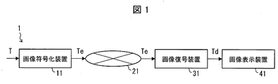
- FIG. 1 is a schematic diagram showing a configuration of an image transmission system 1 according to the present embodiment.
- the image transmission system 1 is a system that transmits a code obtained by encoding an encoding target image, decodes the transmitted code, and displays an image.
- the image transmission system 1 includes an image encoding device 11, a network 21, an image decoding device 31, and an image display device 41.
- the image encoding device 11 receives an image T indicating a single layer image or a plurality of layers.
- a layer is a concept used to distinguish a plurality of pictures when there are one or more pictures constituting a certain time. For example, when the same picture is encoded with a plurality of layers having different image quality and resolution, scalable encoding is performed, and when a picture of a different viewpoint is encoded with a plurality of layers, view scalable encoding is performed.
- inter-layer prediction, inter-view prediction When prediction is performed between pictures of a plurality of layers (inter-layer prediction, inter-view prediction), encoding efficiency is greatly improved. Further, even when prediction is not performed (simultaneous casting), encoded data can be collected.
- the network 21 transmits the encoded stream Te generated by the image encoding device 11 to the image decoding device 31.
- the network 21 is the Internet, a wide area network (WAN: Wide Area Network), a small network (LAN: Local Area Network), or a combination thereof.
- the network 21 is not necessarily limited to a bidirectional communication network, and may be a unidirectional communication network that transmits broadcast waves such as terrestrial digital broadcasting and satellite broadcasting.
- the network 21 may be replaced with a storage medium that records an encoded stream Te such as a DVD (Digital Versatile Disc) or a BD (Blue-ray Disc).
- the image decoding device 31 decodes each of the encoded streams Te transmitted by the network 21, and generates one or a plurality of decoded images Td decoded.
- the image display device 41 displays all or part of one or more decoded images Td generated by the image decoding device 31.
- the image display device 41 includes, for example, a display device such as a liquid crystal display or an organic EL (Electro-luminescence) display.
- a display device such as a liquid crystal display or an organic EL (Electro-luminescence) display.
- a high-quality enhancement layer image is displayed and only a lower processing capability is provided. Displays a base layer image that does not require higher processing capability and display capability as an extension layer.
- X? Y: z is a ternary operator that takes y when x is true (non-zero) and takes z when x is false (0).
- FIG. 2 is a diagram showing a hierarchical structure of data in the encoded stream Te.
- the encoded stream Te illustratively includes a sequence and a plurality of pictures constituting the sequence.
- (A) to (f) of FIG. 2 respectively show an encoded video sequence defining a sequence SEQ, an encoded picture defining a picture PICT, an encoded slice defining a slice S, and an encoded slice defining a slice data
- the encoded video sequence In the encoded video sequence, a set of data referred to by the image decoding device 31 for decoding the sequence SEQ to be processed is defined. As shown in FIG. 2A, the sequence SEQ includes a video parameter set (Video Parameter Set), a sequence parameter set SPS (Sequence Parameter Set), a picture parameter set PPS (Picture Parameter Set), a picture PICT, and an addition. Includes SEI (Supplemental Enhancement Information). Here, the value indicated after # indicates the layer ID.
- FIG. 2 shows an example in which encoded data of # 0 and # 1, that is, layer 0 and layer 1, exists, but the type of layer and the number of layers are not dependent on this.
- the video parameter set VPS is a set of coding parameters common to a plurality of moving images, a plurality of layers included in the moving image, and coding parameters related to individual layers in a moving image composed of a plurality of layers.
- a set is defined.
- the sequence parameter set SPS defines a set of encoding parameters that the image decoding device 31 refers to in order to decode the target sequence. For example, the width and height of the picture are defined. A plurality of SPSs may exist. In that case, one of a plurality of SPSs is selected from the PPS.
- a set of encoding parameters referred to by the image decoding device 31 in order to decode each picture in the target sequence is defined.
- a quantization width reference value (pic_init_qp_minus26) used for picture decoding and a flag (weighted_pred_flag) indicating application of weighted prediction are included.
- the picture PICT includes slices S0 to S NS-1 (NS is the total number of slices included in the picture PICT).
- the coded slice In the coded slice, a set of data referred to by the image decoding device 31 for decoding the slice S to be processed is defined. As shown in FIG. 2C, the slice S includes a slice header SH and slice data SDATA.
- the slice header SH includes an encoding parameter group that is referred to by the image decoding device 31 in order to determine a decoding method of the target slice.
- Slice type designation information (slice_type) for designating a slice type is an example of an encoding parameter included in the slice header SH.
- I slice using only intra prediction at the time of encoding (2) P slice using unidirectional prediction or intra prediction at the time of encoding, (3) B-slice using unidirectional prediction, bidirectional prediction, or intra prediction at the time of encoding may be used.
- the slice header SH may include a reference (pic_parameter_set_id) to the picture parameter set PPS included in the encoded video sequence.
- the slice data SDATA includes a coding tree unit (CTU).
- a CTU is a block of a fixed size (for example, 64x64) that constitutes a slice, and is sometimes called a maximum coding unit (LCU: Large Coding Unit).
- Encoding tree unit As shown in (e) of FIG. 2, a set of data referred to by the image decoding device 31 in order to decode the processing target coding tree unit is defined.
- the coding tree unit is divided by recursive quadtree division (QT division) or binary tree division (BT division).
- a tree-structured node obtained by recursive quadtree partitioning or binary tree partitioning is called a coding node (CN).
- An intermediate node of the quadtree and the binary tree is a coding tree (CT), and the coding tree unit itself is also defined as the highest-level coding tree.
- the CTU includes a QT split flag (cu_split_flag) indicating whether or not to perform QT split, and a BT split mode (split_bt_mode) indicating a split method of BT split.
- cu_split_flag 1
- cu_split_flag 1
- cu_split_flag 0
- the coding node CN is not divided and has one coding unit (CU: Coding Unit) as a node.
- split_bt_mode when split_bt_mode is 2, it is horizontally divided into two coding nodes CN.
- split_bt_mode When split_bt_mode is 1, it is vertically divided into two coding nodes CN.
- the encoding node CN is not divided and has one encoding unit CU as a node.
- the encoding unit CU is a terminal node (leaf node) of the encoding node and is not further divided.
- the encoding unit CU is a basic unit of the encoding process.
- the size of the coding tree unit CTU is 64x64 pixels
- the size of the coding unit is 64x64 pixels, 64x32 pixels, 32x64 pixels, 32x32 pixels, 64x16 pixels, 16x64 pixels, 32x16 pixels, 16x32 pixels, 16x16 pixels.
- the encoding unit As shown in (f) of FIG. 2, a set of data referred to by the image decoding device 31 in order to decode the encoding unit to be processed is defined.
- the encoding unit includes a prediction tree, a conversion tree, and a CU header CUH.
- the CU header defines a prediction mode, a division method (PU division mode), and the like.
- prediction information (a reference picture index, a motion vector, etc.) of each prediction unit (PU) obtained by dividing the coding unit into one or a plurality is defined.
- the prediction unit is one or a plurality of non-overlapping areas constituting the encoding unit.
- the prediction tree includes one or a plurality of prediction units obtained by the above-described division.
- a prediction unit obtained by further dividing the prediction unit is referred to as a “sub-block”.
- the sub block is composed of a plurality of pixels.
- the number of sub-blocks in the prediction unit is one.
- the prediction unit is larger than the size of the sub-block, the prediction unit is divided into sub-blocks. For example, when the prediction unit is 8 ⁇ 8 and the sub-block is 4 ⁇ 4, the prediction unit is divided into four sub-blocks that are divided into two horizontally and two vertically.
- the prediction process may be performed for each prediction unit (sub block).
- Intra prediction is prediction within the same picture
- inter prediction refers to prediction processing performed between different pictures (for example, between display times and between layer images).
- the division method is encoded by the PU division mode (part_mode) of encoded data, and 2Nx2N (the same size as the encoding unit), 2NxN, 2NxnU, 2NxnD, Nx2N, nLx2N, nRx2N, and NxN etc.
- 2NxN and Nx2N indicate 1: 1 symmetrical division
- 2NxnU, 2NxnD and nLx2N and nRx2N indicate 1: 3 and 3: 1 asymmetric division.
- the PUs included in the CU are expressed as PU0, PU1, PU2, and PU3 in this order.
- FIG. 3 specifically show the partition shape (the position of the boundary of the PU partition) in each PU partition mode.
- 3A shows a 2Nx2N partition
- FIGS. 3B, 3C, and 2D show 2NxN, 2NxnU, and 2NxnD partitions (horizontal partitions), respectively.
- E), (f), and (g) show partitions (vertical partitions) in the case of Nx2N, nLx2N, and nRx2N, respectively, and (h) shows an NxN partition.
- the horizontal partition and the vertical partition are collectively referred to as a rectangular partition
- 2Nx2N and NxN are collectively referred to as a square partition.
- the encoding unit is divided into one or a plurality of transform units (TU: Transform Unit), and the position and size of each transform unit are defined.
- TU Transform Unit
- a transform unit is one or more non-overlapping areas that make up a coding unit.
- the conversion tree includes one or a plurality of conversion units obtained by the above division.
- the conversion unit For the division in the conversion tree, an area having the same size as that of the encoding unit is allocated as the conversion unit, and the conversion unit is obtained by dividing the CU into a quadtree (TU division) as in the above-described CU division. There is. The conversion process is performed for each conversion unit.
- TU division quadtree
- the prediction parameter includes prediction list use flags predFlagL0 and predFlagL1, reference picture indexes refIdxL0 and refIdxL1, and motion vectors mvL0 and mvL1.
- the prediction list use flags predFlagL0 and predFlagL1 are flags indicating whether or not reference picture lists called L0 list and L1 list are used, respectively, and a reference picture list corresponding to a value of 1 is used.
- flag indicating whether or not it is XX when “flag indicating whether or not it is XX” is described, when the flag is not 0 (for example, 1) is XX, 0 is not XX, and logical negation, logical product, etc. 1 is treated as true and 0 is treated as false (the same applies hereinafter).
- flag when the flag is not 0 (for example, 1) is XX, 0 is not XX, and logical negation, logical product, etc. 1 is treated as true and 0 is treated as false (the same applies hereinafter).
- other values can be used as true values and false values in an actual apparatus or method.
- Syntax elements for deriving inter prediction parameters included in the encoded data include, for example, PU partition mode part_mode, merge flag merge_flag, merge index merge_idx, inter prediction identifier inter_pred_idc, reference picture index refIdxLX, prediction vector index mvp_LX_idx, There is a difference vector mvdLX.
- the reference picture list is a list including reference pictures stored in the reference picture memory 306.
- FIG. 4 is a conceptual diagram illustrating an example of a reference picture and a reference picture list.
- a rectangle is a picture
- an arrow is a reference relationship of the picture
- a horizontal axis is time
- I, P, and B in the rectangle are an intra picture
- a single prediction picture a bi-prediction picture
- numbers in the rectangle are Indicates the decoding order.
- the decoding order of pictures is I0, P1, B2, B3, and B4
- the display order is I0, B3, B2, B4, and P1.
- FIG. 4B shows an example of the reference picture list.
- the reference picture list is a list representing candidate reference pictures, and one picture (slice) may have one or more reference picture lists.
- the target picture B3 has two reference picture lists, an L0 list RefPicList0 and an L1 list RefPicList1.
- the reference pictures are I0, P1, and B2, and the reference picture has these pictures as elements.
- refIdxLX the reference picture index
- the figure shows an example in which reference pictures P1 and B2 are referred to by refIdxL0 and refIdxL1.
- the prediction parameter decoding (encoding) method includes a merge prediction (merge) mode and an AMVP (Adaptive Motion Vector Prediction) mode.
- the merge flag merge_flag is a flag for identifying these.
- the merge prediction mode is a mode in which the prediction list utilization flag predFlagLX (or inter prediction identifier inter_pred_idc), the reference picture index refIdxLX, and the motion vector mvLX are not included in the encoded data and are derived from the prediction parameters of already processed neighboring PUs
- the AMVP mode is a mode in which the inter prediction identifier inter_pred_idc, the reference picture index refIdxLX, and the motion vector mvLX are included in the encoded data.
- the motion vector mvLX is encoded as a prediction vector index mvp_LX_idx for identifying the prediction vector mvpLX and a difference vector mvdLX.
- the inter prediction identifier inter_pred_idc is a value indicating the type and number of reference pictures, and takes one of PRED_L0, PRED_L1, and PRED_BI.
- PRED_L0 and PRED_L1 indicate that reference pictures managed by the reference picture lists of the L0 list and the L1 list are used, respectively, and that one reference picture is used (single prediction).
- PRED_BI indicates that two reference pictures are used (bi-prediction BiPred), and reference pictures managed by the L0 list and the L1 list are used.
- the prediction vector index mvp_LX_idx is an index indicating a prediction vector
- the reference picture index refIdxLX is an index indicating a reference picture managed in the reference picture list.
- LX is a description method used when L0 prediction and L1 prediction are not distinguished from each other. By replacing LX with L0 and L1, parameters for the L0 list and parameters for the L1 list are distinguished.
- the merge index merge_idx is an index indicating which prediction parameter is used as a prediction parameter of the decoding target PU among prediction parameter candidates (merge candidates) derived from the PU for which processing has been completed.
- the motion vector mvLX indicates a shift amount between blocks on two different pictures.
- a prediction vector and a difference vector related to the motion vector mvLX are referred to as a prediction vector mvpLX and a difference vector mvdLX, respectively.
- Inter prediction identifier inter_pred_idc and prediction list use flag predFlagLX The relationship between the inter prediction identifier inter_pred_idc and the prediction list use flags predFlagL0 and predFlagL1 is as follows and can be converted into each other.
- the flag biPred as to whether it is a bi-prediction BiPred can be derived depending on whether the two prediction list use flags are both 1. For example, it can be derived by the following formula.
- the flag biPred can also be derived depending on whether or not the inter prediction identifier is a value indicating that two prediction lists (reference pictures) are used. For example, it can be derived by the following formula.
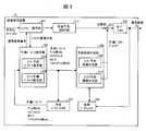
- FIG. 5 is a schematic diagram illustrating a configuration of the image decoding device 31 according to the present embodiment.
- the image decoding device 31 includes an entropy decoding unit 301, a prediction parameter decoding unit (prediction image decoding device) 302, a loop filter 305, a reference picture memory 306, a prediction parameter memory 307, a prediction image generation unit (prediction image generation device) 308, and inversely.
- a quantization / inverse DCT unit 311 and an addition unit 312 are included.
- the prediction parameter decoding unit 302 includes an inter prediction parameter decoding unit 303 and an intra prediction parameter decoding unit 304.
- the predicted image generation unit 308 includes an inter predicted image generation unit 309 and an intra predicted image generation unit 310.
- the entropy decoding unit 301 performs entropy decoding on the coded stream Te input from the outside, and separates and decodes individual codes (syntax elements).
- the separated codes include prediction information for generating a prediction image and residual information for generating a difference image.
- the entropy decoding unit 301 outputs a part of the separated code to the prediction parameter decoding unit 302.
- Some of the separated codes are, for example, a prediction mode predMode, a PU partition mode part_mode, a merge flag merge_flag, a merge index merge_idx, an inter prediction identifier inter_pred_idc, a reference picture index refIdxLX, a prediction vector index mvp_LX_idx, and a difference vector mvdLX.
- Control of which code is decoded is performed based on an instruction from the prediction parameter decoding unit 302.
- the entropy decoding unit 301 outputs the quantization coefficient to the inverse quantization / inverse DCT unit 311.
- the quantization coefficient is a coefficient obtained by performing quantization by performing DCT (Discrete Cosine Transform) on the residual signal in the encoding process.
- the inter prediction parameter decoding unit 303 decodes the inter prediction parameter with reference to the prediction parameter stored in the prediction parameter memory 307 based on the code input from the entropy decoding unit 301.
- the inter prediction parameter decoding unit 303 outputs the decoded inter prediction parameter to the prediction image generation unit 308 and stores it in the prediction parameter memory 307. Details of the inter prediction parameter decoding unit 303 will be described later.
- the intra prediction parameter decoding unit 304 refers to the prediction parameter stored in the prediction parameter memory 307 on the basis of the code input from the entropy decoding unit 301 and decodes the intra prediction parameter.
- the intra prediction parameter is a parameter used in a process of predicting a CU within one picture, for example, an intra prediction mode IntraPredMode.
- the intra prediction parameter decoding unit 304 outputs the decoded intra prediction parameter to the prediction image generation unit 308 and stores it in the prediction parameter memory 307.
- the intra prediction parameter decoding unit 304 may derive different intra prediction modes depending on luminance and color difference.
- the intra prediction parameter decoding unit 304 decodes the luminance prediction mode IntraPredModeY as the luminance prediction parameter and the color difference prediction mode IntraPredModeC as the color difference prediction parameter.
- the luminance prediction mode IntraPredModeY is a 35 mode, and corresponds to planar prediction (0), DC prediction (1), and direction prediction (2 to 34).
- the color difference prediction mode IntraPredModeC uses one of the planar prediction (0), the DC prediction (1), the direction prediction (2 to 34), and the LM mode (35).
- the intra prediction parameter decoding unit 304 decodes a flag indicating whether IntraPredModeC is the same mode as the luminance mode. If the flag indicates that the mode is the same as the luminance mode, IntraPredModeC is assigned to IntraPredModeC, and the flag is luminance. If the mode is different from the mode, planar prediction (0), DC prediction (1), direction prediction (2 to 34), and LM mode (35) may be decoded as IntraPredModeC.
- the loop filter 305 applies filters such as a deblocking filter, a sample adaptive offset (SAO), and an adaptive loop filter (ALF) to the decoded image of the CU generated by the adding unit 312.
- filters such as a deblocking filter, a sample adaptive offset (SAO), and an adaptive loop filter (ALF) to the decoded image of the CU generated by the adding unit 312.
- the reference picture memory 306 stores the decoded image of the CU generated by the adding unit 312 at a predetermined position for each decoding target picture and CU.
- the prediction parameter memory 307 stores the prediction parameter in a predetermined position for each decoding target picture and prediction unit (or sub-block, fixed-size block, pixel). Specifically, the prediction parameter memory 307 stores the inter prediction parameter decoded by the inter prediction parameter decoding unit 303, the intra prediction parameter decoded by the intra prediction parameter decoding unit 304, and the prediction mode predMode separated by the entropy decoding unit 301. .
- the stored inter prediction parameters include, for example, a prediction list utilization flag predFlagLX (inter prediction identifier inter_pred_idc), a reference picture index refIdxLX, and a motion vector mvLX.
- the prediction image generation unit 308 receives the prediction mode predMode input from the entropy decoding unit 301 and the prediction parameter from the prediction parameter decoding unit 302. Further, the predicted image generation unit 308 reads a reference picture from the reference picture memory 306. The prediction image generation unit 308 generates a prediction image of the PU using the input prediction parameter and the read reference picture in the prediction mode indicated by the prediction mode predMode.
- the inter prediction image generation unit 309 uses the inter prediction parameter input from the inter prediction parameter decoding unit 303 and the read reference picture to perform prediction of the PU by inter prediction. Is generated.
- the inter prediction image generation unit 309 performs a motion vector on the basis of the decoding target PU from the reference picture indicated by the reference picture index refIdxLX for a reference picture list (L0 list or L1 list) having a prediction list use flag predFlagLX of 1.
- the reference picture block at the position indicated by mvLX is read from the reference picture memory 306.
- the inter prediction image generation unit 309 performs prediction based on the read reference picture block to generate a prediction image of the PU.
- the inter prediction image generation unit 309 outputs the generated prediction image of the PU to the addition unit 312.
- the intra predicted image generation unit 310 When the prediction mode predMode indicates the intra prediction mode, the intra predicted image generation unit 310 performs intra prediction using the intra prediction parameter input from the intra prediction parameter decoding unit 304 and the read reference picture. Specifically, the intra predicted image generation unit 310 reads, from the reference picture memory 306, neighboring PUs that are pictures to be decoded and are in a predetermined range from the decoding target PUs among the PUs that have already been decoded.
- the predetermined range is, for example, one of the left, upper left, upper, and upper right adjacent PUs when the decoding target PU sequentially moves in the so-called raster scan order, and differs depending on the intra prediction mode.
- the raster scan order is an order in which each row is sequentially moved from the left end to the right end in each picture from the upper end to the lower end.
- the intra predicted image generation unit 310 performs prediction in the prediction mode indicated by the intra prediction mode IntraPredMode for the read adjacent PU, and generates a predicted image of the PU.
- the intra predicted image generation unit 310 outputs the generated predicted image of the PU to the adding unit 312.
- the intra prediction image generation unit 310 performs planar prediction (0), DC prediction (1), direction according to the luminance prediction mode IntraPredModeY.
- Prediction image of luminance PU is generated by any of prediction (2 to 34), and planar prediction (0), DC prediction (1), direction prediction (2 to 34), LM mode according to color difference prediction mode IntraPredModeC
- a predicted image of the color difference PU is generated by any of (35).
- the inverse quantization / inverse DCT unit 311 inversely quantizes the quantization coefficient input from the entropy decoding unit 301 to obtain a DCT coefficient.
- the inverse quantization / inverse DCT unit 311 performs inverse DCT (Inverse Discrete Cosine Transform) on the obtained DCT coefficient to calculate a residual signal.
- the inverse quantization / inverse DCT unit 311 outputs the calculated residual signal to the addition unit 312.
- the addition unit 312 adds the prediction image of the PU input from the inter prediction image generation unit 309 or the intra prediction image generation unit 310 and the residual signal input from the inverse quantization / inverse DCT unit 311 for each pixel, Generate a decoded PU image.
- the adding unit 312 stores the generated decoded image of the PU in the reference picture memory 306, and outputs a decoded image Td in which the generated decoded image of the PU is integrated for each picture to the outside.
- FIG. 6 is a block diagram illustrating a configuration of the image encoding device 11 according to the present embodiment.
- the image encoding device 11 includes a prediction image generation unit 101, a subtraction unit 102, a DCT / quantization unit 103, an entropy encoding unit 104, an inverse quantization / inverse DCT unit 105, an addition unit 106, a loop filter 107, and a prediction parameter memory.
- the prediction parameter encoding unit 111 includes an inter prediction parameter encoding unit 112 and an intra prediction parameter encoding unit 113.
- the predicted image generation unit 101 generates, for each picture of the image T, a predicted image P of the prediction unit PU for each encoding unit CU that is an area obtained by dividing the picture.
- the predicted image generation unit 101 reads a decoded block from the reference picture memory 109 based on the prediction parameter input from the prediction parameter encoding unit 111.
- the prediction parameter input from the prediction parameter encoding unit 111 is, for example, a motion vector in the case of inter prediction.
- the predicted image generation unit 101 reads a block at a position on the reference image indicated by the motion vector with the target PU as a starting point.
- the prediction parameter is, for example, an intra prediction mode.
- a pixel value of an adjacent PU used in the intra prediction mode is read from the reference picture memory 109, and a predicted image P of the PU is generated.
- the predicted image generation unit 101 generates a predicted image P of the PU using one prediction method among a plurality of prediction methods for the read reference picture block.
- the predicted image generation unit 101 outputs the generated predicted image P of the PU to the subtraction unit 102.
- FIG. 7 is a schematic diagram illustrating a configuration of an inter predicted image generation unit 1011 included in the predicted image generation unit 101.
- the inter prediction image generation unit 1011 includes a motion compensation unit 10111 and a weight prediction unit 10112. Since the motion compensation unit 10111 and the weight prediction unit 10112 have the same configurations as the motion compensation unit 3091 and the weight prediction unit 3094 described above, description thereof is omitted here.
- the prediction image generation unit 101 generates a prediction image P of the PU based on the pixel value of the reference block read from the reference picture memory, using the parameter input from the prediction parameter encoding unit.
- the predicted image generated by the predicted image generation unit 101 is output to the subtraction unit 102 and the addition unit 106.
- the subtraction unit 102 subtracts the signal value of the predicted image P of the PU input from the predicted image generation unit 101 from the pixel value of the corresponding PU of the image T, and generates a residual signal.
- the subtraction unit 102 outputs the generated residual signal to the DCT / quantization unit 103.
- the DCT / quantization unit 103 performs DCT on the residual signal input from the subtraction unit 102 and calculates a DCT coefficient.
- the DCT / quantization unit 103 quantizes the calculated DCT coefficient to obtain a quantization coefficient.
- the DCT / quantization unit 103 outputs the obtained quantization coefficient to the entropy coding unit 104 and the inverse quantization / inverse DCT unit 105.
- the entropy encoding unit 104 receives the quantization coefficient from the DCT / quantization unit 103 and receives the encoding parameter from the prediction parameter encoding unit 111.
- Examples of input encoding parameters include codes such as a reference picture index refIdxLX, a prediction vector index mvp_LX_idx, a difference vector mvdLX, a prediction mode predMode, and a merge index merge_idx.
- the entropy encoding unit 104 generates an encoded stream Te by entropy encoding the input quantization coefficient and encoding parameter, and outputs the generated encoded stream Te to the outside.
- the inverse quantization / inverse DCT unit 105 inversely quantizes the quantization coefficient input from the DCT / quantization unit 103 to obtain a DCT coefficient.
- the inverse quantization / inverse DCT unit 105 performs inverse DCT on the obtained DCT coefficient to calculate a residual signal.
- the inverse quantization / inverse DCT unit 105 outputs the calculated residual signal to the addition unit 106.
- the addition unit 106 adds the signal value of the prediction image P of the PU input from the prediction image generation unit 101 and the signal value of the residual signal input from the inverse quantization / inverse DCT unit 105 for each pixel, and performs decoding. Generate an image.
- the adding unit 106 stores the generated decoded image in the reference picture memory 109.
- the loop filter 107 performs a deblocking filter, a sample adaptive offset (SAO), and an adaptive loop filter (ALF) on the decoded image generated by the adding unit 106.
- SAO sample adaptive offset
- ALF adaptive loop filter
- the prediction parameter memory 108 stores the prediction parameter generated by the encoding parameter determination unit 110 at a predetermined position for each encoding target picture and CU.
- the reference picture memory 109 stores the decoded image generated by the loop filter 107 at a predetermined position for each picture to be encoded and each CU.
- the encoding parameter determination unit 110 selects one set from among a plurality of sets of encoding parameters.
- the encoding parameter is a parameter to be encoded that is generated in association with the above-described prediction parameter or the prediction parameter.
- the predicted image generation unit 101 generates a predicted image P of the PU using each of these encoding parameter sets.
- the encoding parameter determination unit 110 calculates a cost value indicating the amount of information and the encoding error for each of a plurality of sets.
- the cost value is, for example, the sum of a code amount and a square error multiplied by a coefficient ⁇ .
- the code amount is the information amount of the encoded stream Te obtained by entropy encoding the quantization error and the encoding parameter.
- the square error is the sum between pixels regarding the square value of the residual value of the residual signal calculated by the subtracting unit 102.
- the coefficient ⁇ is a real number larger than a preset zero.
- the encoding parameter determination unit 110 selects a set of encoding parameters that minimizes the calculated cost value.
- the entropy encoding unit 104 outputs the selected set of encoding parameters to the outside as the encoded stream Te, and does not output the set of unselected encoding parameters.
- the encoding parameter determination unit 110 stores the determined encoding parameter in the prediction parameter memory 108.
- the prediction parameter encoding unit 111 derives a format for encoding from the parameters input from the encoding parameter determination unit 110 and outputs the format to the entropy encoding unit 104. Deriving the format for encoding is, for example, deriving a difference vector from a motion vector and a prediction vector. Also, the prediction parameter encoding unit 111 derives parameters necessary for generating a prediction image from the parameters input from the encoding parameter determination unit 110 and outputs the parameters to the prediction image generation unit 101.
- the parameter necessary for generating the predicted image is, for example, a motion vector in units of sub-blocks.
- the inter prediction parameter encoding unit 112 derives an inter prediction parameter such as a difference vector based on the prediction parameter input from the encoding parameter determination unit 110.
- the inter prediction parameter encoding unit 112 derives parameters necessary for generating a prediction image to be output to the prediction image generating unit 101, and an inter prediction parameter decoding unit 303 (see FIG. 6 and the like) derives inter prediction parameters.
- Some of the configurations are the same as the configuration to be performed. The configuration of the inter prediction parameter encoding unit 112 will be described later.
- the intra prediction parameter encoding unit 113 derives a format (for example, MPM_idx, rem_intra_luma_pred_mode) for encoding from the intra prediction mode IntraPredMode input from the encoding parameter determination unit 110.
- a format for example, MPM_idx, rem_intra_luma_pred_mode
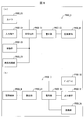
- FIG. 10 is a block diagram showing the main configuration of the image decoding apparatus according to this embodiment.
- illustration of some members included in the block diagram shown in FIG. 10 is omitted.
- members having the same functions as those shown in FIG. 5 are denoted by the same reference numerals, and description thereof is omitted.
- the image decoding apparatus 31 includes a decoding module 9, a CT information decoding unit 10, a predicted image generation unit 308, an inverse quantization / inverse DCT conversion unit 311, a reference picture memory 306, an addition unit 312, a loop filter. 305, a header decoding unit 19 and a CU decoding unit 20 are provided.
- the CU decoding unit 20 further includes a PU information decoding unit 12 and a TT information decoding unit 13 (division information decoding unit, division unit), and the TT information decoding unit 13 further includes a TU decoding unit 22.
- the decoding module 9 performs a decoding process for decoding a syntax value from binary. More specifically, the decoding module 9 decodes and decodes a syntax value encoded by an entropy encoding method such as CABAC based on encoded data and syntax type supplied from a supplier. Returns the syntax value to the supplier.
- an entropy encoding method such as CABAC
- the sources of encoded data and syntax type are the CT information decoding unit 10 and the CU decoding unit 20 (PU information decoding unit 12 and TT information decoding unit 13).
- the header decoding unit 19 decodes the VPS (video parameter set), SPS, PPS, and slice header of the encoded data input from the image encoding device 11.
- the CT information decoding unit 10 uses the decoding module 9 to perform coding tree unit and coding tree decoding processing on the coded data input from the image coding device 11. Specifically, the CT information decoding unit 10 decodes the CTU information and the CT information from the encoded data by the following procedure.
- the CT information decoding unit 10 uses the decoding module 9 to decode the tree unit header CTUH from the CTU information included in the CTU.
- the CT information decoding unit 10 decodes, from the CT information included in the CT, a QT division flag indicating whether or not the target CT is QT-divided and a BT division mode indicating a BT division method of the target CT
- the target CT is recursively divided and decoded until the QT division flag and the BT division mode no longer notify further division.
- the tree unit footer CTUF is decoded from the CTU information.
- the tree unit header CTUH and the tree unit footer CTUF include coding parameters referred to by the image decoding device 31 in order to determine a decoding method of the target coding tree unit.
- the CT information may include parameters applied in the target CT and lower coding nodes.
- the CU decoding unit 20 includes a PU information decoding unit 12 and a TT information decoding unit 13, and decodes PUI information and TTI information of the lowest coding tree CT (ie, CU).
- PU information decoding unit In the PU information decoding unit 12, PU information (merge flag (merge_flag), merge index (merge_idx), prediction vector index (mvp_idx), reference image index (ref_idx), inter prediction identifier (inter_pred_flag), and difference vector (mvd) of each PU And the like) are decrypted using the decryption module 9.
- PU information (merge flag (merge_flag), merge index (merge_idx), prediction vector index (mvp_idx), reference image index (ref_idx), inter prediction identifier (inter_pred_flag), and difference vector (mvd) of each PU And the like) are decrypted using the decryption module 9.
- the TT information decoding unit 13 decodes the TT information (TU partition flag SP_TU (split_transform_flag), TU residual flag CBP_TU (cbf_cb, cbf_cr, cbf_luma), and TU) of the transformation tree TT using the decoding module 9.
- the TT information decoding unit 13 includes a TU decoding unit 22.
- the TU decoding unit 22 decodes the QP update information (quantization correction value) when a residual is included in the TU.
- the QP update information is a value indicating a difference value from the quantization parameter predicted value qPpred, which is a predicted value of the quantization parameter QP.
- the TU decoding unit 22 decodes the quantized prediction residual (residual_coding).
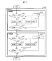
- FIG. 11 is a flowchart illustrating a schematic operation of the CT information decoding unit 10 according to an embodiment of the present invention.
- CT information decoding S1400 by the CT information decoding unit 10 QT information decoding and BT information decoding are performed.
- QT information decoding and BT information decoding by the CT information decoding unit 10 will be described in order.
- the CT information decoding unit 10 decodes CT information from encoded data, and recursively decodes a coding tree CT (coding_quadtree).
- the CT information decoding unit 10 determines whether or not the decoded CT information includes a QT division flag. If the CT information decoding unit 10 determines that there is a QT division flag, the process proceeds to S1421. Otherwise, the process proceeds to S1422.
- CT information decoding unit 10 determines that there is a QT division flag, it decodes the QT division flag (split_cu_flag) that is a syntax element.
- the CT information decoding unit 10 omits decoding of the QT division flag split_cu_flag from the encoded data in other cases, that is, when the QT division flag split_cu_flag does not appear in the encoded data (not present).
- the QT division flag split_cu_flag is derived as 0 (infer).
- the CT information decoding unit 10 performs QT division. Specifically, the CT information decoding unit 10 decodes four coding trees CT in the CT layer one layer below. The CT information decoding unit 10 continues the QT information decoding started from S1411 even in the lower coding tree CT.
- the CT information decoding unit 10 decodes the CT information from the encoded data, and recursively decodes the coding tree CT (coding_binarytree).
- the QT depth (before division) is first set to 0, and then the QT depth is incremented by 1 for each QT division.
- the CT information decoding unit 10 determines whether or not the decoded CT information has a BT division mode. If the CT information decoding unit 10 determines that there is a BT division mode, the process proceeds to S1461. Otherwise, the process proceeds to S1462.
- the CT information decoding unit 10 omits the decoding of the BT partition mode split_bt_mode from the encoded data in other cases, that is, when the BT partition mode split_bt_mode does not appear in the encoded data, and the BT partition mode
- the split_bt_mode is derived as 0.
- the CT information decoding unit 10 performs BT division. Specifically, when the BT partition mode is 1, the CT information decoding unit 10 decodes two coding trees CT when the BT partition mode is 1, and the BT partition mode is 2. Performs vertical division and decodes two coding trees CT. The CT information decoding unit 10 continues the BT information decoding started from S1451 even in the lower coding tree CT. At this time, the BT depth before division is first set to 0, and thereafter the BT depth is incremented by 1 for each BT division.
- the QT tree and the BT tree are separate layers (the QT tree and the BT tree have a hierarchical relationship. That is, the QT tree is recursively between the QT trees. And the BT tree is recursively split between BT trees (there can be a BT tree as a lower node of the QT tree, but there is no QT tree as a lower node of the BT tree) Decoding method. In this method, QT division cannot be performed after BT division, but it is not necessary to determine whether or not there is a QT division flag after BT division.
- this embodiment is not limited to this, and the QT tree and the BT tree are in the same layer (the QT tree and the BT tree do not have a hierarchical relationship. That is, the CT tree in which the QT tree and the BT tree are combined)
- a decoding method that assumes that a BT tree exists as a lower node of a QT tree and a QT tree also exists in a lower node of the BT tree) Also good.
- both QT division and BT division can be selected, that is, QT division can be performed even after BT division, but it is necessary to determine the presence or absence of the QT division flag every time.
- TU partitioning for CUs is limited to only one layer.
- the present embodiment includes a plurality of TU partition patterns. Specifically, the hierarchy of TU division for CU is limited to 0 (that is, no division) or 1 (that is, field division, horizontal 4 division, and vertical 4 division are performed for one layer).
- a plurality of TU division patterns (in this example, three patterns including a square-shaped division, a horizontal division into four, and a vertical division into four) are provided.
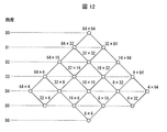
- FIG. 12 shows an example of the CU hierarchy and the CU shape corresponding to the hierarchy.
- the CU has a different shape for each layer.
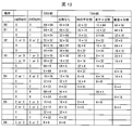
- the TU partition pattern is limited to that shown in FIG. 13 according to the CU hierarchy and shape.
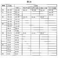
- FIG. 13 is a list of examples of TU division patterns corresponding to each shape of the CU. That is, when the shape of the target CU is 64 ⁇ 64, TU partitioning for the target CU is limited to TU partitioning into the TU shape illustrated in FIG. 13 according to the TU partition mode.
- a TU partition flag (partition information) indicating whether or not the CU is to be TU-divided
- a TU partition indicating a TU partition mode of TU partition The mode (division information) is encoded by including it in the TT information for one layer.
- the TU partition flag is 0, it indicates that TU partition is not performed, and when the TU partition flag is 1, it indicates that TU partition is performed.
- a horizontal split that divides into four in the horizontal direction.
- the method of assigning a value to the TU split mode tuSplitMode is not limited to the above, and another assignment method may be used.
- information (division information) regarding TU division is expressed using two values of a TU division flag indicating the presence / absence of division and a TU division mode indicating a division method (division pattern).
- a configuration using only the TU division mode may be used. In this case, it is assumed that one of the values of the TU division mode includes no division.
- the TU partitioning for the CU is limited to only one layer, so that the complexity of encoding / decoding of moving images can be reduced.
- the number of TU partitions is increased from one (field-shaped division) to three (field-shaped division, horizontal 4-division, and vertical 4-division). Therefore, it becomes possible to deal with various patterns.
- the plurality of division patterns are not limited to rice field division, horizontal four divisions, and vertical four divisions. As will be described later, 8 ⁇ 8 division and 16 ⁇ 16 division may be added.
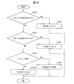
- FIG. 14 is a flowchart illustrating a schematic operation of the TT information decoding unit 13 according to an embodiment of the present invention.
- the TT information decoding unit 13 decodes the TT information from the encoded data and decodes the conversion tree TT.
- the TT information decoding unit 13 determines whether the target TU size (target CU size, target TU size) is equal to or smaller than the maximum TU size and larger than the minimum TU size.
- the TT information decoding unit 13 derives the TU partition flag when the above condition is not satisfied, that is, when the TU partition flag does not appear in the encoded data. The derivation of the TU division flag will be described later.
- the TT information decoding unit 13 decodes the TU partition flag that is a syntax element.
- the TT information decoding unit 13 refers to the TU division flag and decodes the TU division mode when the TU division flag indicates division.
- the TT information decoding unit 13 decodes the TU partition mode from the encoded data, and performs TU partitioning in the TU partition mode specified by the decoded TU partition mode. The derivation of the TU division mode will be described later.
- the TT information decoding unit 13 decodes a TU residual flag indicating whether or not a residual is included in the target TU.
- the TT information decoding unit 13 decodes the AMT flag amt_flag.
- the TU decoding unit 22 of the TT information decoding unit 13 decodes the TU based on the TU residual flag and the AMT flag amt_flag.
- the TT information decoding unit 13 performs the same process in other TUs and continues the TT information decoding.
- FIG. 15 is a flowchart illustrating a schematic operation of the TT information decoding unit 13 according to an embodiment of the present invention.
- the TT information decoding unit 13 determines whether or not the target TU size is larger than the maximum TU size.
- the TT information decoding unit 13 derives the TU partition flag as 1 because the TU partition of the target TU is necessary. In this case, the TU partition flag does not appear in the encoded data, and the encoding of the TU partition flag by the image encoding device 11 and the decoding by the image decoding device 31 are not performed.
- the TT information decoding unit 13 determines whether the target TU size is equal to or smaller than the minimum TU size.
- the TU partition flag appears in the encoded data, and the TU partition flag is encoded by the encoder and decoded by the decoder (S1522).
- FIG. 16 is a flowchart illustrating a schematic operation of the TT information decoding unit 13 according to an embodiment of the present invention.
- the TT information decoding unit 13 determines whether or not the TU partition flag is 1.
- the TT information decoding unit 13 determines whether or not the division mode indicates rice field division.
- the TT information decoding unit 13 determines whether or not the division mode is horizontal four division when the division mode does not indicate rice field division.
- the TT information decoding unit 13 determines whether or not the division mode is vertical four divisions.
- the TT information decoding unit 13 determines, as a TU shape (TUwidth, TUheight) one level lower, a bit shifted by sftx and sfty in which the CU shape (CUwidth, CUheight) is set.
- TUwidth CUwidth >> sftx
- TUheight CUheight >> sfty
- log2CUwidth, log2CUheight log2TUwidth, log2TUheight
- CUwidth 1 ⁇ log2CUwidth
- CUheight 1 ⁇ log2CUheight
- TUwidth 1 ⁇ log2TUwidth
- TUheight 1 ⁇ log2TUheight.
- the TT information decoding unit 13 is given the shape (CUwidth, CUheight) of each CU together with the depth Depth (cqtDepth, cbtDepth) of each CU.
- the TT information decoding unit 13 repeatedly performs the processes from (S1511) to (S1531) shown in FIG. For example, when the TU division mode is no division, the above process is performed once. When the TU division mode is a rice field division, horizontal four division, or vertical four division, the above process is performed four times.
- CU is divided into TUs by this series of processing.
- this series of processing when the CU is divided into TUs for one layer by the above-described series of processing, no further TU division is performed.
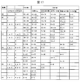
- Fig. 17 shows a list of TU division pattern examples according to each shape of the CU.
- the TU partition mode includes 8 ⁇ 8 partition up to a layer with a large CU size (for example, a layer that does not include a partition pattern into 8 ⁇ 8 size (D3 in this figure)).
- FIG. 18 is a flowchart illustrating a schematic operation of the TT information decoding unit 13 according to an embodiment of the present invention.
- the TT information decoding unit 13 determines whether or not the division mode is 8 ⁇ 8 division when the division mode does not indicate vertical four division.
- the TT information decoding unit 13 determines, as a TU shape (TUwidth, TUheight) one level lower, a bit shifted by sftx and sfty in which the CU shape (CUwidth, CUheight) is set.
- the division mode is not limited to 8 ⁇ 8 division.
- division into 16 ⁇ 16 sizes (hereinafter referred to as 16 ⁇ 16 division) may be used.
- FIG. 19 shows a list of examples of TU division patterns corresponding to each shape of the CU.
- the TU partition mode includes 16 ⁇ 16 partition up to a layer with a large CU size (for example, a layer that does not include a partition pattern into 16 ⁇ 16 size (D1 in this figure)). ing.
- FIG. 20 shows a list of TU division pattern examples corresponding to each shape of the CU in this case.
- the TU partition mode includes 16 ⁇ 16 partition up to a predetermined layer (for example, a layer that does not include a partition pattern into 16 ⁇ 16 size (D1 in this figure)).
- a predetermined layer for example, a layer that does not include a partition pattern into 16 ⁇ 16 size (D1 in this figure)
- 8 ⁇ 8 division is included in the TU division mode.
- the TU division hierarchy is set to 0 (ie, no division) by BT division, and the TU division hierarchy for the CU obtained by QT division is 0 (ie, no division) or 1 (ie, rice field). Division, horizontal 4-division, and vertical 4-division for one layer).
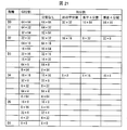
- FIG. 21 is a list of examples of division patterns of TUs according to each shape of the CU. That is, when the shape of the target CU is a square such as 64 ⁇ 64, TU partitioning for the target CU is limited to TU partitioning into the TU shape shown in FIG. 21 according to the TU partition mode.
- TU partitioning for CUs obtained by QT partitioning is limited to only one layer, and TU partitioning for CUs obtained by BT partitioning is not performed, so that the complexity of video encoding / decoding is reduced. Encoding efficiency can be maintained while reducing.
- FIG. 22 is a flowchart illustrating a schematic operation of the TT information decoding unit 13 according to an embodiment of the present invention.
- the TT information decoding unit 13 decodes the TT information from the encoded data and decodes the conversion unit TU.
- the TT information decoding unit 13 determines whether or not the target TU size is equal to or smaller than the maximum TU size and larger than the minimum TU size and is only QT division.
- the TT information decoding unit 13 is given the depth Depth (cqtDepth, cbtDepth) of each CU together with the shape (CUwidth, CUheight) of each CU.
- cbtDepth 0 in the target TU
- the TT information decoding unit 13 can determine that there is no BT division and only QT division.
- the TT information decoding unit 13 derives (infers) the TU partition flag when the above condition is not satisfied, that is, when the TU partition flag does not appear in the encoded data. The derivation of the TU division flag will be described later.
- FIG. 23 is a flowchart illustrating a schematic operation of the TT information decoding unit 13 according to an embodiment of the present invention.
- the TT information decoding unit 13 stabilizes whether the target CU is BT-divided. That is, it is determined whether the target CU is a CU without BT partitioning or a CU obtained by BT partitioning (presence / absence of BT partitioning in the target CU).
- the TT information decoding unit 13 determines that the target CU is a BT-divided CU, the TU division flag is set to 0 because the TU of the target CU is not performed. That is, the TT information decoding unit 13 determines the CU shape (CUwidth, CUheight) as the TU shape (TUwidth, TUheight) one level below.
- the TU partition mode for the CU obtained by QT partition is not limited to no partition, rice field partition, horizontal four partition, and vertical four partition.
- the TU partition mode for a CU obtained by QT partitioning may be limited to no partitioning and rice field partitioning.
- the hierarchy of TU division for CU is limited to 0 (that is, no division) or 1 (that is, rice field division is performed for one layer).
- the TU partition pattern for CUs obtained by QT partitioning is limited to no partitioning or rice field partitioning, so that the TU partition pattern is shown in FIG. 24 according to the CU hierarchy and shape.
- Restricted to FIG. 24 is a list of examples of division patterns of TUs according to each shape of the CU. That is, when the shape of the target CU is a square such as 64 ⁇ 64, TU division for the target CU is limited to TU division into the TU shape shown in FIG. 24 according to the TU division mode.
- Modification 2 As described above, if the CU size is large, it may not be possible to perform appropriate division according to the image characteristics with only one TU division. Therefore, as the TU division mode of the CU, division into 8 ⁇ 8 size (8 ⁇ 8 division) may be used in addition to the square division, horizontal division, or vertical division. In this case, the division mode for the CU obtained by the QT division is not divided, the square character division, the horizontal four division, the vertical four division, and the 8 ⁇ 8 division, and the division mode for the CU obtained by the BT division is not divided and Limit to 8x8 divisions.
- Fig. 25 shows a list of examples of TU division patterns corresponding to each shape of the CU. As shown in FIG. 25, up to a hierarchy having a large CU size (D3 in this figure), 8 ⁇ 8 division is included in the TU division mode. In this case, the TT information decoding unit 13 performs TT information decoding in accordance with the processing illustrated in FIGS. 14 and 15, and derivation of the TU partition mode is performed in accordance with the processing illustrated in FIG. 18.
- the TT information decoding unit 13 derives the TU partitioning mode according to the process shown in FIG. 18, in the case of a CU obtained by QT partitioning, the TU partitioning mode is not divided, the rice field is divided, and horizontal 4 All steps can be taken to determine whether it is a division, a vertical 4 division, or an 8 ⁇ 8 division.
- the TU division mode is limited to no division or 8 ⁇ 8 division, and in order to determine whether the TU division mode is no division or 8 ⁇ 8 division. , S1751, S1771, and S1791.
- FIG. 26 shows a list of TU division pattern examples according to each shape of the CU. As shown in FIG. 26, up to a hierarchy having a large CU size (D1 in this figure), the TU partition mode includes 16 ⁇ 16 partitions.
- FIG. 27 shows a list of TU division pattern examples corresponding to each shape of the CU in this case.
- the TU partitioning mode includes 16 ⁇ 16 partitioning up to a predetermined layer (D1 in this figure), and TU partitioning is performed in the subsequent layers (D2 and D3 in this figure).
- the mode contains 8x8 splits.
- the TU partitioning shown in the first embodiment is performed only when the prediction mode is inter prediction, and the TU partitioning is not performed when the prediction mode is intra prediction.
- the TU partition hierarchy for the CU is 0 (that is, no partition) or 1 (that is, the U-shaped partition, the horizontal four partitions, and the vertical four partitions are performed for one layer. ).
- the TU partition hierarchy for the CU is limited to 0 or 1, so that the TU partition pattern is shown in FIG. 13 according to the CU layer and shape. It is restricted to the thing.
- TU partitioning for the CU is limited to only one layer, and in the case of intra prediction when prediction is performed, TU partitioning for the CU is not performed. Encoding efficiency can be maintained while reducing the complexity of encoding / decoding.
- FIG. 28 is a flowchart illustrating a schematic operation of the TT information decoding unit 13 according to an embodiment of the present invention.
- the TT information decoding unit 13 decodes the TT information from the encoded data and decodes the conversion unit TU.
- the TT information decoding unit 13 determines whether or not the target TU size is equal to or smaller than the maximum TU size and larger than the minimum TU size, and the prediction mode is inter prediction.
- the TT information decoding unit 13 is given the prediction mode (predMode) of each CU together with the shape (CUwidth, CUheight) of each CU and the depth Depth (cqtDepth, cbtDepth) of each CU.
- the TT information decoding unit 13 derives the TU partition flag when the above condition is not satisfied, that is, when the TU partition flag does not appear in the encoded data. The derivation of the TU division flag will be described later.
- FIG. 29 is a flowchart illustrating a schematic operation of the TT information decoding unit 13 according to an embodiment of the present invention.
- the TT information decoding unit 13 determines whether or not the prediction mode of the target TU is inter prediction.
- the TT information decoding unit 13 decodes the TU partition flag from the encoded data because there is a possibility of performing TU partitioning of the target TU. (S1691).
- the TT information decoding unit 13 determines that the prediction mode of the target TU is not inter prediction (that is, intra prediction), it does not perform TU partitioning of the target TU. Is derived as 0. That is, the TT information decoding unit 13 determines the CU shape (CUwidth, CUheight) as the TU shape (TUwidth, TUheight) one level below.
- the TU partitioning performed when the prediction mode is inter prediction is not limited to the above.
- the TU partitioning shown in the modified examples (FIGS. 17, 19, and 20) of the first embodiment may be performed, or the second embodiment (FIG. 21).
- the TU partitioning shown in Modification Example 1 (FIG. 24) and Modification Example 2 (FIGS. 25 to 27) of the second embodiment may be performed.
- Transformation Quantization, inverse transformation, inverse quantization
- transformation unit TU This conversion is performed by the inverse quantization / inverse DCT unit 311.
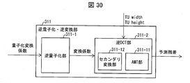
- FIG. 30 is a functional block diagram showing a configuration example of the inverse quantization / inverse DCT unit 311.
- the inverse quantization / inverse DCT unit 311 includes an inverse quantization unit 311-1 and an inverse DCT unit 311-2.
- the inverse quantization unit 311-1 performs inverse quantization on the quantized transform coefficient qd [] [] decoded by the TU decoding unit 22 in the TT information decoding unit 13, and derives a transform coefficient d [] [].
- the inverse quantization unit 311-1 transmits the derived transform coefficient d [] [] to the inverse DCT unit 311-2.
- the inverse DCT unit 311-2 inversely transforms the received transform coefficient d [] [] to restore the prediction residual r [] [] (also expressed as D in FIG. 10).
- the restored prediction residual r [] [] is sent from the inverse DCT unit 311-2 to the adder 312.
- the inverse DCT unit 311-2 includes an AMT unit 311-11 and a secondary conversion unit 311-12.
- the inverse DCT unit 311-2 performs adaptive core transformation (Adaptive Multi Core Transform: AMT) and secondary transformation. Can be used.
- AMT Adaptive Multi Core Transform
- secondary transform section 311-12 receives information indicating that secondary transform is performed from TT information decoding section 13, and uses transform coefficient d [d] [] received from inverse quantization section 311-1 as secondary.
- the modified conversion coefficient d [] [] is restored by conversion.
- the restored modified conversion coefficient d [] [] is transmitted from the secondary conversion unit 311-12 to the AMT unit 311-11. If the secondary conversion is not performed, the conversion coefficient d [] [] received by the secondary conversion unit 311-12 is transmitted from the secondary conversion unit 311-12 to the AMT unit 311-11 as it is.
- AMT The AMT unit 311-11 can adaptively switch conversion bases.
- conversion that is switched by an explicit flag, index, prediction mode, or the like is referred to as AMT.
- the conversion used in AMT is a separation type conversion composed of vertical conversion and horizontal conversion.
- the conversion bases of this conversion are DCT2, DST7, DCT8, DST1, and DCT5.
- DCT5 Tij w0 * w1 * (2 / (2N-1)) 1/2 * cos (2 ⁇ * i * j / (2N-1))
- DCT8 Tij (4 / (2N + 1)) 1/2 * cos ( ⁇ * (2i + 1) * (2j + 1) / (4N + 2))
- DST1 Tij (2 / (N + 1)) 1/2 * sin ( ⁇ * (i + 1) * (j + 1) / (N + 1))
- the AMT unit 311-11 refers to the AMT flag (amt_flag) decoded from the encoded data, and switches between fixed conversion that does not perform switching based on the index and selective conversion that performs switching based on the index.
- amt_flag 0
- amt_flag_ 1
- the AMT unit 311-11 further decodes the AMT index amt_idx used for selection from the encoded data, and switches the conversion according to the prediction mode predMode and the AMT index amt_idx.
- the AMT flag is decoded in units of CU or TU
- the AMT index amt_idx is decoded in units of TU
- the unit of decoding (switching) is not limited to this.
- the fixed conversion is DCT2 or DST7 for the conventional horizontal / vertical conversion.
- the AMT unit 311-11 selects from the plurality of transform bases using the prediction mode predMode and the AMT index amt_idx.
- FIG. 31A is a table showing conversion sets
- FIG. 31B is a diagram showing basis functions of each conversion basis.
- the AMT unit 311-11 selects a transform set to be used from the three transform sets.
- Each transformation set has two transformation bases.
- the conversion set 0 has two conversion bases DST7 and DCT8 as a set.
- the AMT unit 311-11 uses the AMT index amt_idx (amt_idx_hor and amt_idx_ver) to specify which of these two conversion bases is used.
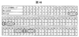
- the AMT unit 311-11 determines which transform set to use among the three transform sets (0, 1, 2) for intra prediction with reference to the intra prediction mode.
- FIG. 32 shows a reference table at this time.
- FIG. 32 shows which transformation set is selected for horizontal transformation and vertical transformation in each of 67 types of intra prediction modes.
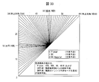
- FIG. 33 is a schematic diagram showing 67 types of intra prediction modes. As shown in FIG. 33, there are 67 types (0 to 66) of intra prediction modes.
- 0, 1, and 2 represent conversion sets 0, 1, and 2, respectively.
- the intra prediction mode is 10
- the value of horizontal conversion (Horizontal) in the figure is 0. Since conversion set 0 is used and the value of vertical conversion (Vertical) in the figure is 0, conversion set 0 is also used for vertical conversion.
- the AMT described above will be specifically described with reference to FIG.
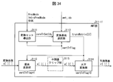
- the AMT unit 311-11 in FIG. 34 is an example of the AMT unit 311-11 in FIG.
- the AMT unit 311-11 in FIG. 34 includes a transformation set derivation unit 3111 that derives an index coreTrSetIdx of a transformation set to be used, a transformation base selection unit 3112 that derives a transformation base using the coreTrSetIdx, and a transformation coefficient d [] [].
- a vertical conversion unit 3113 for performing vertical conversion and a horizontal conversion unit 3114 for performing horizontal conversion.
- the conversion base selection unit 3112 selects a conversion base to be used from the conversion set specified by coreTrSetIdx using the AMT index amt_idx.
- the conversion base selection unit 3112 derives a conversion matrix transMatrix [] [] indicated by the selected conversion base.
- the transformation base selection unit 3112 notifies the transformation matrix transMatrix [] [] derived for vertical / horizontal transformation to the vertical transformation unit 3113 and the horizontal transformation unit 3114, and uses the transformation coefficient d [] [] as the prediction residual r. Convert to [] [].
- the vertical conversion unit 3113 converts the conversion coefficient d [] [] into an intermediate value e [] [] by vertical one-dimensional conversion, and sends the intermediate value e [] [] to the intermediate value clip unit 3115.
- the intermediate value clipping unit 3115 derives the intermediate value g [] [] by clipping the intermediate value e [] [], and sends it to the horizontal conversion unit 3114.
- the horizontal conversion unit 3114 converts the intermediate value g [] [] into a prediction residual r [] [].
- the prediction residual r [] [] is sent from the horizontal conversion unit 3114 to the adder 312.
- the AMT unit 311-11 designates which one of the two transformation bases to use by using the AMT index amt_idx (amt_idx_hor and amt_idx_ver).
- amt_idx amt_idx_ver ⁇ 1 + amt_idx_hor, and the conversion base is selected based on this index value.
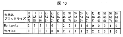
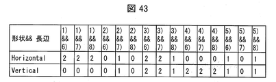
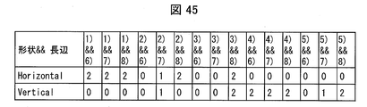
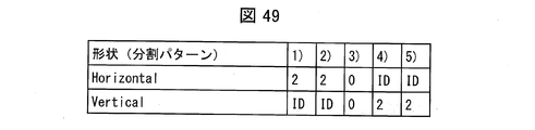
- the AMT unit 311-11 determines which transform set to use among the three transform sets (0, 1, 2) of inter prediction with reference to the shape of the target TU.
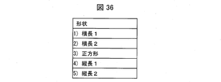
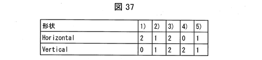
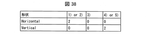
- the reference table at this time is shown in FIG. FIG. 35 shows which conversion set is selected for horizontal conversion and vertical conversion of each of the TU shapes shown in 1) to 5).
- 0, 1, and 2 represent conversion sets 0, 1, and 2, respectively.
- Conversion set 2 is also used for vertical conversion.
- the horizontal shape and the horizontal / vertical conversion of the vertically long shape may be symmetrical to each other. That is, the horizontally long horizontal conversion and the vertically long vertical conversion, the horizontally long vertical conversion and the vertically long horizontal conversion may be equal.
- Horizontally long 2 represents a shape that is horizontally longer than 3) a square
- Horizontally long 1 represents a shape that is horizontally longer than 2) Horizontally long 2
- Longitudinal 1 represents 3) a shape that is vertically longer than a square
- Longitudinal 2 represents a shape that is longer than 5) Longitudinal 1
- the shapes 1), 2), 4) and 5) can be classified according to the aspect ratio, for example. For example, if the aspect ratio (horizontal: vertical) is 2: 1, 2) is horizontal 2. If the aspect ratio is 4: 1 or more, 1) is horizontal 1, and if the aspect ratio is 1: 2, 5) is vertical. 2) If the aspect ratio is 1: 4 or more, 4) Longitudinal 1 is set.
- the shape can be derived from the following expression.
- the transform set deriving unit 3111 refers to the reference table and derives an index coreTrSetIdx of the transform set to be used next based on the shape of the TU. Note that the transformation set derivation unit 3111 is given a prediction mode (predMode) and the shape (TUwidth, TUheight) of each TU.
- the AMT unit 311-11 selects not only the AMT index in the intra prediction but also the intra prediction mode, and selects the transform base in the inter prediction. Since the conversion base is selected with reference to the shape of the TU, it is easy to select an appropriate conversion base according to the target TU. For example, if the TU has an edge in the vertical direction, a vertically long shape is easily selected, and if the TU has an edge in the horizontal direction, a horizontally long shape is easy to select. By selecting, it becomes easy to select a conversion base suitable for the prediction error.
- the shape of the TU referred to by the conversion set deriving unit 3111 is not limited to five types.
- the conversion set deriving unit 3111 may select a conversion set used for horizontal conversion and vertical conversion of each of the three types of TU shapes with reference to the reference table shown in FIG.
- the three types of shapes are landscape, square, and portrait.
- Longitudinal 1 and 5) Longitudinal 2, that is, TUwidth ⁇ TUheight corresponds to the longitudinal.
- the conversion set deriving unit 3111 may select a conversion set used for horizontal conversion and vertical conversion of each TU shape with reference to the reference table shown in FIG. In this figure, 3)
- the transformation set used for horizontal transformation and vertical transformation is the same transformation set (transformation set 0) as inter prediction. This is because the inter prediction of a square shape does not have a large slope characteristic as seen in a vertical shape or a horizontal shape in the bias of the residual, so it is preferable to use the same transformation set, particularly a transformation set 0 having symmetry This is because. Note that it is clear from the top diagram of FIG. 31B that DST7 and DCT8, which are the bases of the pair constituting the transformation set 0 (FIG. 31A), are symmetrical with each other. .
- the horizontal shape 1), 2), the square shape 3), and the vertically long shape 4), 5) include at least horizontal conversion or vertical conversion.
- One different transformation set is used.
- Modification 1 In the inter prediction, what the transform set deriving unit 3111 refers to is not limited to the TU shape and the AMT index.
- the transformation set deriving unit 3111 may derive the transformation set index with reference to the TU shape, the TU block size, and the AMT index.
- the block size is TUwidth + TUheight.
- the reference table at this time is shown in FIG. FIG. 40 shows which conversion set is selected for horizontal conversion and vertical conversion for each combination of five types of TU shapes and four types of TU block sizes. In the figure, 0, 1, and 2 represent conversion sets 0, 1, and 2, respectively.
- FIG. 6 the relationship between the block size of the TU shown in 6) to 9) and the shape of the TU shown in 1) to 5) is shown in FIG.
- 6) represents that the TU block size is 96 or more
- 7) represents that the TU block size is 48 or more
- 8) represents that the TU block size is 24 or more.
- 9) indicates that the block size of the TU is less than 24.
- the size threshold and method are not limited to this.
- a logarithmic size such as log2TUwidth + log2TUheight may be used for determining the block size.
- TUs may be classified using block area TU area (product of TU width TUwidth and height TUheight) instead of the sum of TU width TUwidth and height TUheight. If logarithm, log2TUwidth + log2TUheight may be considered to correspond to the area.
- the conversion base is selected by referring not only to the AMT index and the shape of the TU but also to the block size of the TU, it is easy to select an appropriate conversion base according to the target TU.
- the conversion set deriving unit 3111 selects a conversion set to be used for horizontal conversion and vertical conversion of each combination of five types of TU shapes and four types of TU block sizes with reference to the reference table shown in FIG. May be.
- the transform set deriving unit 3111 refers to the TU shape, the TU block size, and the AMT index.
- the transformation set derivation unit 3111 may derive the transformation set index with reference to the TU shape, the long side of the TU, and the AMT index.
- the reference table at this time is shown in FIG. FIG. 43 shows which conversion set is selected for horizontal conversion and vertical conversion for each combination of five types of TU shapes and long sides of three types of TUs.
- 0, 1, and 2 represent conversion sets 0, 1, and 2, respectively.
- the horizontal conversion value (Horizontal) in the figure is 2, so the conversion set 1 is used for the horizontal conversion. Since the value of vertical conversion (Vertical) is 0, conversion set 0 is also used for vertical conversion.
- FIG. 44 shows the relationship between the long sides of the three types (6) to 8)) of the TU and the shapes of the five types (1) to 5)) of the TU.
- the shapes of the five types of TUs (1) to 5)) are as shown in FIG.
- 6) represents that the length of the long side of the TU is 64 or more
- 7) represents that the length of the long side of the TU is 32 or more
- 8) represents the length of the long side of the TU. Is less than 32.
- the conversion base is selected by referring not only to the AMT index and the shape of the TU but also to the long side of the TU, so that an appropriate conversion base can be easily selected depending on the target TU.
- the conversion set derivation unit 3111 selects a conversion set to be used for horizontal conversion and vertical conversion of each combination of five types of TU shapes and long sides of three types of TUs with reference to the reference table shown in FIG. May be.
- the transformation set derivation unit 3111 refers to the shape of the target TU, not the shape of the target TU.
- the first modification may refer to the block size (CUwidth + CUheight) of the target CU together
- the second modification may refer to the long side of the target CU.
- FIG. 33 there are 65 types of direction prediction in intra prediction.
- intra prediction it is desirable to select a transform base suitable for the intra prediction mode, but accuracy as high as direction prediction is not required. Therefore, in the present embodiment, in intra prediction, in some intra prediction modes, one of horizontal conversion and vertical conversion is performed, the other conversion is skipped, and only scaling (shift or multiplication) is performed (IDentity transform: ID).
- the transform set deriving unit 3111 selects a transform set to be used from the three transform sets.
- the transform set deriving unit 3111 determines which transform set to use among the three transform sets (0, 1, 2) with reference to the intra prediction mode.
- the reference table at this time is shown in FIG.
- FIG. 46 shows which conversion set is selected for horizontal conversion and vertical conversion in each of 67 types of intra prediction modes.
- 0, 1, and 2 represent conversion sets 0, 1, and 2, respectively.
- the conversion set deriving unit 3111 selects the conversion set 2 for horizontal conversion and selects the ID for vertical conversion.
- the conversion set deriving unit 3111 selects ID for horizontal conversion and selects conversion set 2 for vertical conversion.
- the transformation set derivation unit 3111 refers to the reference table and derives the index of the transformation set to be used next by the intra prediction mode.
- the processing after deriving the index of the transformation set is as shown in the fourth embodiment.
- one of horizontal conversion and vertical conversion is performed based on the intra prediction mode, the other conversion is skipped, and only scaling is performed, so that encoding efficiency can be maintained while reducing the amount of calculation. it can.
- the intra prediction mode using the ID is not limited to the horizontal direction (intra prediction mode 18) and the vertical direction (intra prediction mode 50).
- intra prediction modes from the vertical direction to ⁇ 3 for example, intra prediction modes 47 to 49, 51 to 53
- An ID may be used for.
- the conversion set deriving unit 3111 selects the conversion set 2 for horizontal conversion and performs vertical conversion. Choose ID.
- the conversion set deriving unit 3111 selects ID for horizontal conversion and selects conversion set 2 for vertical conversion.
- the intra prediction mode using the ID is not particularly limited.
- the ID may be used instead of the vertical conversion in the intra prediction modes 15 to 21, or the ID may be used instead of the horizontal conversion in the intra prediction modes 47 to 53. It may be used.
- the neighborhood direction in the horizontal direction is not limited to the intra prediction mode from ⁇ 3 to the horizontal direction, and the neighborhood direction in the vertical direction is not limited to the intra prediction mode from ⁇ 3 to the vertical direction.
- ID may be used instead of vertical conversion only in the horizontal direction or in the vicinity direction of the horizontal direction, or ID may be used instead of horizontal conversion only in the vertical direction or in the vicinity direction of the vertical direction.
- the transform set deriving unit 3111 performs horizontal transform and conversion for some intra prediction modes only when the size of the target TU is smaller than a predetermined size (for example, 8 ⁇ 8 or less or 16 ⁇ 16 or less). One conversion of the vertical conversion may be performed, and the ID may be used for the other conversion.
- a predetermined size for example, 8 ⁇ 8 or less or 16 ⁇ 16 or less.
- One conversion of the vertical conversion may be performed, and the ID may be used for the other conversion.
- FIG. 47 is a flowchart for explaining the schematic operation of the transform set deriving unit 3111 according to an embodiment of the present invention.
- the conversion set deriving unit 3111 determines whether the size of the target TU is smaller than a predetermined size.
- the conversion set deriving unit 3111 determines that the size of the target TU is greater than or equal to a predetermined size, the conversion set deriving unit 3111 selects a conversion set using the reference table of FIG.
- Mode 2 Of the intra prediction modes, the intra prediction modes estimated to have a high probability of being applied in the target TU are included in the MPM candidates (candModeList). On the other hand, the remaining mode excluding the intra prediction mode corresponding to the MPM candidate from the entire intra prediction mode is called non-MPM (RemIntraPredMode). Further, the non-MPM is divided into a first Gr (rem_selected_mode) and a second Gr (rem_non_selected_mode).
- the conversion set deriving unit 3111 may perform one of horizontal conversion and vertical conversion for the intra prediction mode included in the second non-MPM second Gr (rem_non_selected_mode), and may use an ID for the other conversion.
- predMode INTRA
- the transform set deriving unit 3111 refers to the intra prediction mode and the intra prediction parameter, and the intra prediction mode included in the second MPr of the non-MPM is as follows. One of horizontal conversion and vertical conversion is performed, and the ID is used for the other conversion.
- the intra prediction parameters include candModeList, RemIntraPredMode, rem_selected_mode, rem_non_selected_mode, and the like.
- the transform set deriving unit 3111 selects a transform set to be used from the three transform sets.
- the transform set derivation unit 3111 determines which transform set to use among the three transform sets (0, 1, 2) with reference to the intra prediction mode and the intra prediction parameter.
- the reference table at this time is shown in FIG.
- FIG. 48 shows which conversion set is selected for horizontal conversion and vertical conversion of each intra prediction mode included in the first Gr or the second Gr of the MPM candidate or the non-MPM.
- 0, 1, and 2 represent conversion sets 0, 1, and 2, respectively, and the numbers on the left represent horizontal conversion sets, and the numbers on the right represent vertical conversion sets.
- the transformation set deriving unit 3111 uses transformation set 0 for one of horizontal transformation and vertical transformation. Select either 1 or 2, and select the ID for the other conversion.
- the transformation set derivation unit 3111 refers to the reference table and derives the index of the transformation set to be used next by the intra prediction mode.
- the processing after deriving the index of the transformation set is as shown in the fourth embodiment.
- the intra prediction mode using ID is not limited to all intra prediction modes included in the second MPr of non-MPM.
- the transform set deriving unit 3111 may perform one of horizontal transform and vertical transform for a part of the intra prediction mode included in the non-MPM second Gr, and may use the ID for the other transform.
- the set deriving unit 3111 performs horizontal conversion and vertical conversion, and uses the ID for the other conversion.
- the intra prediction mode using the ID is not limited to all or two intra prediction modes included in the non-MPM second Gr.
- one intra prediction mode included in the non-MPM second Gr one of horizontal conversion and vertical conversion may be performed, and an ID may be used for the other conversion.
- the transform set deriving unit 3111 only includes the intra-non-MPM second Gr when the size of the target TU is smaller than a predetermined size (for example, 8 ⁇ 8 or less or 16 ⁇ 16 or less).
- a predetermined size for example, 8 ⁇ 8 or less or 16 ⁇ 16 or less.
- the conversion set deriving unit 3111 operates according to the flowchart shown in FIG. 47, but in S1821, the conversion set is selected using the reference table of FIG.
- the transformation set deriving unit 3111 refers to the shape of the TU. If the transformation set deriving unit 3111 is a horizontally long rectangular TU, the transformation set deriving unit 3111 uses the ID instead of the vertical transformation and uses the vertically long rectangular TU. In the case of, ID is used instead of horizontal conversion.
- the transformation set derivation unit 3111 selects a transformation set to be used from the three transformation sets.
- the conversion set deriving unit 3111 determines which conversion set to use among the three conversion sets (0, 1, 2) with reference to the shape of the TU.
- the reference table at this time is shown in FIG.
- FIG. 49 shows which conversion set is selected for horizontal conversion and vertical conversion for each of the five types of TU shapes.
- 0, 1, and 2 represent conversion sets 0, 1, and 2, respectively.
- the shapes of the five types of TUs (1) to 5)) are as shown in FIG.
- the conversion set deriving unit 3111 selects the conversion set 2 for the horizontal conversion and selects the ID for the vertical conversion.
- the conversion set deriving unit 3111 selects an ID for horizontal conversion and selects a conversion set 2 for vertical conversion.
- the conversion set deriving unit 3111 refers to the reference table and derives the index of the conversion set to be used next based on the shape of the TU.
- the processing after deriving the index of the transformation set is as shown in the fourth embodiment.
- one of horizontal conversion and vertical conversion is performed based on the shape of the target TU, the other conversion is skipped, and only scaling is performed, so that encoding efficiency is maintained while reducing the amount of calculation. Can do.
- amt_idx_ver amt_idx
- the conversion set deriving unit 3111 may select a conversion set to be used for horizontal conversion and vertical conversion for each of the five types of TU shapes with reference to the reference table shown in FIG. In this figure, only when the shape of TU is 1) horizontally long 1, conversion set deriving unit 3111 selects conversion set 2 for horizontal conversion and ID for vertical conversion. Also, only when the TU shape is 4) vertically long 1, the conversion set deriving unit 3111 selects an ID for horizontal conversion and selects a conversion set 2 for vertical conversion.
- the rectangular TU may be subjected to one of horizontal conversion and vertical conversion and the ID is used for the other conversion when the block size of the TU is equal to or smaller than the threshold.
- the transformation set derivation unit 3111 refers to the shape of the TU and the block size of the TU, and if the block size is equal to or smaller than the threshold value, if the block is a horizontally long TU, the ID is used instead of the vertical transformation. If the TU has a vertically long rectangular shape, ID is used instead of horizontal conversion.
- FIG. 51 shows which conversion set is selected for horizontal conversion and vertical conversion for each combination of five types of TU shapes and four types of TU block sizes.
- the shapes of the five types of TUs (1) to 5)) are as shown in FIG. 36, and the block sizes of the four types of TUs (6) to 9)) are as shown in FIG. It is.
- the conversion set deriving unit 3111 when the block size of the TU is a threshold value (9 in this figure, less than 24), when the TU shape is 1) horizontally long 1, the conversion set deriving unit 3111 performs conversion for horizontal conversion. Select Set 2 and select ID for vertical conversion. If the block size of the TU is a threshold value (9 in this figure, less than 24), the transform set deriving unit 3111 selects an ID for horizontal conversion and vertical when the TU shape is 4) vertically long 1. Conversion 2 is selected for conversion.
- the conversion set deriving unit 3111 refers to the shape of the TU and the long side of the TU, and if the length of the long side is equal to or less than the threshold, the conversion set deriving unit 3111 ID is used instead, and ID is used instead of horizontal conversion in the case of a vertically long rectangular TU.
- FIG. 52 shows which conversion set is selected for horizontal conversion and vertical conversion for each combination of five types of TU shapes and long sides of three types of TUs.
- the shapes of the five types (1) to 5)) of the TU are as shown in FIG. 36, and the long sides of the four types (6) to 8)) of the TU are as shown in FIG. It is.
- the transformation set derivation unit 3111 Conversion set 2 is selected for horizontal conversion, and ID is selected for vertical conversion. If the block size of the TU is a threshold (8 in this figure, less than 32), the transform set deriving unit 3111 uses the ID for horizontal conversion when the shape of the TU is 4) vertically long 1 or 5) vertically long 2. And conversion set 2 is selected for vertical conversion.
- FIG. 53 is a flowchart illustrating a schematic operation of the transform set deriving unit 3111 according to an embodiment of the present invention.
- the transform set deriving unit 3111 determines whether the prediction mode is inter prediction for the target TU.
- the transform set deriving unit 3111 selects a transform set using the reference table of FIG. 49 when it is determined that the prediction mode is inter prediction.
- the transform set deriving unit 3111 selects a transform set using the reference table of FIG.
- the conversion set may be selected using any one of the reference tables of FIGS. 50 to 52 instead of FIG.
- the conversion set may be selected using the reference table of FIG. 48 instead of FIG.
- the ID may be used for both horizontal conversion and vertical conversion. That is, when the shape of the target TU is 1) landscape 1 or 4) portrait 1 shown in FIG. 36, the inverse DCT section 311-2 does not perform AMT but performs only secondary conversion.
- FIG. 54 is a flowchart illustrating a schematic operation of the transform set deriving unit 3111 according to an embodiment of the present invention.
- the transformation set deriving unit 3111 has a size (width / height) of the target TU that is equal to or greater than a predetermined value (that is, 1) 64 ⁇ 16, 64 ⁇ 8, 64 ⁇ 4, 32 ⁇ 8, 32 ⁇ 4, and 16 ⁇ 4 that are horizontally long 1), Alternatively, if the size (height / width) of the target TU is greater than or equal to the specified value (that is, 4) 16x64, 8x64, 4x64, 8x32, 4x32, 4x16 with a vertical length of 1), horizontal conversion and vertical conversion ID is used for both conversions.
- a predetermined value that is, 1
- the size (height / width) of the target TU is greater than or equal to the specified value (that is, 4) 16x64, 8x64, 4x64, 8x32, 4x32, 4x16 with a vertical length of 1)
- horizontal conversion and vertical conversion ID is used for both conversions.
- the conversion set may be selected using any one of the reference tables of FIGS. 37, 40, 43, and 49 to 52 instead of FIG.
- a part of the image encoding device 11 and the image decoding device 31 in the above-described embodiment for example, the entropy decoding unit 301, the prediction parameter decoding unit 302, the loop filter 305, the predicted image generation unit 308, the inverse quantization / inverse DCT.
- the prediction parameter encoding unit 111 may be realized by a computer.
- the program for realizing the control function may be recorded on a computer-readable recording medium, and the program recorded on the recording medium may be read by a computer system and executed.
- the “computer system” is a computer system built in either the image encoding device 11 or the image decoding device 31 and includes hardware such as an OS and peripheral devices.
- the “computer-readable recording medium” refers to a storage device such as a portable medium such as a flexible disk, a magneto-optical disk, a ROM, a CD-ROM, or a hard disk built in a computer system.
- the “computer-readable recording medium” is a medium that dynamically holds a program for a short time, such as a communication line when transmitting a program via a network such as the Internet or a communication line such as a telephone line,
- a volatile memory inside a computer system serving as a server or a client may be included and a program that holds a program for a certain period of time.
- the program may be a program for realizing a part of the functions described above, and may be a program capable of realizing the functions described above in combination with a program already recorded in a computer system.
- part or all of the image encoding device 11 and the image decoding device 31 in the above-described embodiment may be realized as an integrated circuit such as an LSI (Large Scale Integration).
- LSI Large Scale Integration
- Each functional block of the image encoding device 11 and the image decoding device 31 may be individually made into a processor, or a part or all of them may be integrated into a processor.
- the method of circuit integration is not limited to LSI, and may be realized by a dedicated circuit or a general-purpose processor. Further, in the case where an integrated circuit technology that replaces LSI appears due to progress in semiconductor technology, an integrated circuit based on the technology may be used.
- the image encoding device 11 and the image decoding device 31 described above can be used by being mounted on various devices that perform transmission, reception, recording, and reproduction of moving images.
- the moving image may be a natural moving image captured by a camera or the like, or may be an artificial moving image (including CG and GUI) generated by a computer or the like.
- FIG. 8 is a block diagram showing a configuration of a transmission device PROD_A in which the image encoding device 11 is mounted.
- the transmission apparatus PROD_A modulates a carrier wave with an encoding unit PROD_A1 that obtains encoded data by encoding a moving image, and with the encoded data obtained by the encoding unit PROD_A1.
- a modulation unit PROD_A2 that obtains a modulation signal and a transmission unit PROD_A3 that transmits the modulation signal obtained by the modulation unit PROD_A2 are provided.
- the above-described image encoding device 11 is used as the encoding unit PROD_A1.
- Transmission device PROD_A as a source of moving images to be input to the encoding unit PROD_A1, a camera PROD_A4 that captures moving images, a recording medium PROD_A5 that records moving images, an input terminal PROD_A6 for inputting moving images from the outside, and An image processing unit A7 that generates or processes an image may be further provided.
- FIG. 8A illustrates a configuration in which the transmission apparatus PROD_A includes all of these, but some of them may be omitted.
- the recording medium PROD_A5 may be a recording of a non-encoded moving image, or a recording of a moving image encoded by a recording encoding scheme different from the transmission encoding scheme. It may be a thing. In the latter case, a decoding unit (not shown) for decoding the encoded data read from the recording medium PROD_A5 in accordance with the recording encoding method may be interposed between the recording medium PROD_A5 and the encoding unit PROD_A1.
- FIG. 8 is a block diagram showing a configuration of a receiving device PROD_B in which the image decoding device 31 is mounted.
- the receiving device PROD_B includes a receiving unit PROD_B1 that receives the modulated signal, a demodulating unit PROD_B2 that obtains encoded data by demodulating the modulated signal received by the receiving unit PROD_B1, and a demodulator.
- a decoding unit PROD_B3 that obtains a moving image by decoding the encoded data obtained by the unit PROD_B2.
- the above-described image decoding device 31 is used as the decoding unit PROD_B3.
- the receiving device PROD_B is a display destination PROD_B4 for displaying a moving image, a recording medium PROD_B5 for recording a moving image, and an output terminal for outputting the moving image to the outside as a supply destination of the moving image output by the decoding unit PROD_B3 PROD_B6 may be further provided.
- FIG. 8B illustrates a configuration in which all of these are provided in the receiving device PROD_B, but some of them may be omitted.
- the recording medium PROD_B5 may be used for recording a non-encoded moving image, or is encoded using a recording encoding method different from the transmission encoding method. May be. In the latter case, an encoding unit (not shown) for encoding the moving image acquired from the decoding unit PROD_B3 according to the recording encoding method may be interposed between the decoding unit PROD_B3 and the recording medium PROD_B5.
- the transmission medium for transmitting the modulation signal may be wireless or wired.
- the transmission mode for transmitting the modulated signal may be broadcasting (here, a transmission mode in which the transmission destination is not specified in advance) or communication (here, transmission in which the transmission destination is specified in advance). Refers to the embodiment). That is, the transmission of the modulation signal may be realized by any of wireless broadcasting, wired broadcasting, wireless communication, and wired communication.
- a terrestrial digital broadcast broadcasting station (broadcasting equipment, etc.) / Receiving station (such as a television receiver) is an example of a transmitting device PROD_A / receiving device PROD_B that transmits and receives a modulated signal by wireless broadcasting.
- a broadcasting station (such as broadcasting equipment) / receiving station (such as a television receiver) of cable television broadcasting is an example of a transmitting device PROD_A / receiving device PROD_B that transmits and receives a modulated signal by cable broadcasting.
- a server workstation, etc.
- Client television receiver, personal computer, smartphone, etc.
- VOD Video On Demand
- video sharing service using the Internet is a transmission device that transmits and receives modulated signals via communication.
- PROD_A / receiving device PROD_B normally, either a wireless or wired transmission medium is used in a LAN, and a wired transmission medium is used in a WAN.
- the personal computer includes a desktop PC, a laptop PC, and a tablet PC.
- the smartphone also includes a multi-function mobile phone terminal.
- the video sharing service client has a function of encoding a moving image captured by the camera and uploading it to the server. That is, the client of the video sharing service functions as both the transmission device PROD_A and the reception device PROD_B.
- FIG. 9A is a block diagram showing a configuration of a recording apparatus PROD_C equipped with the image encoding device 11 described above.
- the recording apparatus PROD_C includes an encoding unit PROD_C1 that obtains encoded data by encoding a moving image, and the encoded data obtained by the encoding unit PROD_C1 on a recording medium PROD_M.
- the above-described image encoding device 11 is used as the encoding unit PROD_C1.
- the recording medium PROD_M may be of a type built into the recording device PROD_C, such as (1) HDD (Hard Disk Drive) or SSD (Solid State Drive), or (2) SD memory. It may be of the type connected to the recording device PROD_C, such as a card or USB (Universal Serial Bus) flash memory, or (3) DVD (Digital Versatile Disc) or BD (Blu-ray Disc: registration) Or a drive device (not shown) built in the recording device PROD_C.
- HDD Hard Disk Drive
- SSD Solid State Drive
- SD memory such as a card or USB (Universal Serial Bus) flash memory, or (3) DVD (Digital Versatile Disc) or BD (Blu-ray Disc: registration) Or a drive device (not shown) built in the recording device PROD_C.
- the recording device PROD_C is a camera PROD_C3 that captures moving images as a source of moving images to be input to the encoding unit PROD_C1, an input terminal PROD_C4 for inputting moving images from the outside, and a reception for receiving moving images
- a unit PROD_C5 and an image processing unit PROD_C6 for generating or processing an image may be further provided.
- FIG. 9A illustrates a configuration in which the recording apparatus PROD_C includes all of these, but some of them may be omitted.
- the receiving unit PROD_C5 may receive a non-encoded moving image, or may receive encoded data encoded by a transmission encoding scheme different from the recording encoding scheme. You may do. In the latter case, a transmission decoding unit (not shown) that decodes encoded data encoded by the transmission encoding method may be interposed between the reception unit PROD_C5 and the encoding unit PROD_C1.
- Examples of such a recording device PROD_C include a DVD recorder, a BD recorder, an HDD (Hard Disk Drive) recorder, and the like (in this case, the input terminal PROD_C4 or the receiver PROD_C5 is a main source of moving images). .
- a camcorder in this case, the camera PROD_C3 is a main source of moving images
- a personal computer in this case, the receiving unit PROD_C5 or the image processing unit C6 is a main source of moving images
- a smartphone this In this case, the camera PROD_C3 or the reception unit PROD_C5 is a main source of moving images
- the like is also an example of such a recording apparatus PROD_C.
- FIG. 9 is a block showing a configuration of a playback device PROD_D in which the above-described image decoding device 31 is mounted.
- the playback device PROD_D reads a moving image by decoding a read unit PROD_D1 that reads encoded data written to the recording medium PROD_M and a read unit PROD_D1 that reads the encoded data. And a decoding unit PROD_D2 to obtain.
- the above-described image decoding device 31 is used as the decoding unit PROD_D2.
- the recording medium PROD_M may be of the type built into the playback device PROD_D, such as (1) HDD or SSD, or (2) such as an SD memory card or USB flash memory. It may be of the type connected to the playback device PROD_D, or (3) may be loaded into a drive device (not shown) built in the playback device PROD_D, such as a DVD or BD. Good.
- the playback device PROD_D has a display unit PROD_D3 that displays a moving image as a supply destination of the moving image output by the decoding unit PROD_D2, an output terminal PROD_D4 that outputs the moving image to the outside, and a transmission unit that transmits the moving image.
- PROD_D5 may be further provided.
- FIG. 9B illustrates a configuration in which the playback apparatus PROD_D includes all of these, but some of them may be omitted.
- the transmission unit PROD_D5 may transmit a non-encoded moving image, or transmits encoded data encoded by a transmission encoding scheme different from the recording encoding scheme. You may do. In the latter case, it is preferable to interpose an encoding unit (not shown) that encodes a moving image using a transmission encoding method between the decoding unit PROD_D2 and the transmission unit PROD_D5.
- Examples of such a playback device PROD_D include a DVD player, a BD player, and an HDD player (in this case, an output terminal PROD_D4 to which a television receiver or the like is connected is a main moving image supply destination). .
- a television receiver in this case, the display PROD_D3 is a main supply destination of moving images
- a digital signage also referred to as an electronic signboard or an electronic bulletin board
- the display PROD_D3 or the transmission unit PROD_D5 is the main supply of moving images
- Desktop PC in this case, output terminal PROD_D4 or transmission unit PROD_D5 is the main video source
- laptop or tablet PC in this case, display PROD_D3 or transmission unit PROD_D5 is video
- a smartphone which is a main image supply destination
- a smartphone in this case, the display PROD_D3 or the transmission unit PROD_D5 is a main moving image supply destination
- the like are also examples of such a playback device PROD_D.
- Each block of the image decoding device 31 and the image encoding device 11 described above may be realized in hardware by a logic circuit formed on an integrated circuit (IC chip), or may be a CPU (Central Processing Unit). You may implement
- IC chip integrated circuit
- CPU Central Processing Unit
- each of the above devices includes a CPU that executes instructions of a program that realizes each function, a ROM (Read Memory) that stores the program, a RAM (RandomAccess Memory) that expands the program, the program, and various data
- a storage device such as a memory for storing the.
- the object of the embodiment of the present invention is a record in which the program code (execution format program, intermediate code program, source program) of the control program for each of the above devices, which is software that realizes the above-described functions, is recorded in a computer-readable manner This can also be achieved by supplying a medium to each of the above devices, and reading and executing the program code recorded on the recording medium by the computer (or CPU or MPU).
- Examples of the recording medium include tapes such as magnetic tapes and cassette tapes, magnetic disks such as floppy (registered trademark) disks / hard disks, CD-ROMs (Compact Disc Read-Only Memory) / MO discs (Magneto-Optical discs).
- tapes such as magnetic tapes and cassette tapes
- magnetic disks such as floppy (registered trademark) disks / hard disks
- CD-ROMs Compact Disc Read-Only Memory
- MO discs Magnetic-Optical discs
- IC cards including memory cards
- Cards such as optical cards
- Semiconductor memories such as flash ROM, or PLD (Programmable logic device ) Or FPGA (Field Programmable Gate Gate Array) or the like.
- each of the above devices may be configured to be connectable to a communication network, and the program code may be supplied via the communication network.
- the communication network is not particularly limited as long as it can transmit the program code.
- Internet intranet, extranet, LAN (Local Area Network), ISDN (Integrated Services Digital Network), VAN (Value-Added Network), CATV (Community Area Antenna / television / Cable Television), Virtual Private Network (Virtual Private Network) Network), telephone line network, mobile communication network, satellite communication network, and the like.
- the transmission medium constituting the communication network may be any medium that can transmit the program code, and is not limited to a specific configuration or type.
- IEEE Institute of Electrical and Electronic Engineers 1394, USB, power line carrier, cable TV line, telephone line, ADSL (Asymmetric Digital Subscriber Line) line, etc. wired such as IrDA (Infrared Data Association) or remote control , BlueTooth (registered trademark), IEEE802.11 wireless, HDR (High Data Rate), NFC (Near Field Communication), DLNA (Digital Living Network Alliance: registered trademark), mobile phone network, satellite line, terrestrial digital broadcasting network, etc. It can also be used wirelessly.
- the embodiment of the present invention can also be realized in the form of a computer data signal embedded in a carrier wave in which the program code is embodied by electronic transmission.
- Embodiments of the present invention are preferably applied to an image decoding apparatus that decodes encoded data in which image data is encoded, and an image encoding apparatus that generates encoded data in which image data is encoded. it can. Further, the present invention can be suitably applied to the data structure of encoded data generated by an image encoding device and referenced by the image decoding device.
Landscapes
- Engineering & Computer Science (AREA)
- Multimedia (AREA)
- Signal Processing (AREA)
- Physics & Mathematics (AREA)
- Discrete Mathematics (AREA)
- General Physics & Mathematics (AREA)
- Compression Or Coding Systems Of Tv Signals (AREA)
Abstract
画像復号装置(31)は、符号化ツリーユニットにおけるリーフノードに対する四分木分割の分割有無及び分割方法を示す分割情報を復号し、分割情報を参照して、リーフノードに対して、四分木分割を行わない、または、分割情報が示す分割方法を用いて1階層分の四分木分割を行うTT情報復号部(13)を備える。
Description
本発明は、予測画像生成装置、画像復号装置、及び画像符号化装置に関する。
動画像を効率的に伝送または記録するために、動画像を符号化することによって符号化データを生成する画像符号化装置、及び、当該符号化データを復号することによって復号画像を生成する画像復号装置が用いられている。
具体的な動画像符号化方式としては、例えば、H.264/AVCやHEVC(High-Efficiency Video Coding)にて提案されている方式などが挙げられる。
このような動画像符号化方式においては、動画像を構成する画像(ピクチャ)は、画像を分割することにより得られるスライス、スライスを分割することにより得られる符号化単位(符号化ユニット(Coding Unit:CU)と呼ばれることもある)、及び、符号化単位を分割することより得られるブロックである予測ユニット(PU)、変換ユニット(TU)からなる階層構造により管理され、CUごとに符号化/復号される。
また、このような動画像符号化方式においては、通常、入力画像を符号化/復号することによって得られる局所復号画像に基づいて予測画像が生成され、当該予測画像を入力画像(原画像)から減算して得られる予測残差(「差分画像」または「残差画像」と呼ぶこともある)が符号化される。予測画像の生成方法としては、画面間予測(インター予測)、及び、画面内予測(イントラ予測)が挙げられる。
また、近年の動画像符号化及び復号の技術として非特許文献1が挙げられる。
さらに、近年では、スライスを構成する符号化ツリーユニット(CTU:Coding Tree Unit)の分割方式として、CTUを、四分木(quad tree)分割するQT分割に加えて、二分木(binary tree)分割するBT分割が導入されている。このBT分割には、水平分割と垂直分割とが含まれる。
"Algorithm Description of Joint Exploration Test Model 2", JVET-B1002, Joint Video Exploration Team (JVET) of ITU-T SG 16 WP 3 and ISO/IEC JTC 1/SC 29/WG 11, 20-26 February 2016
CTUの分割方式として、QT分割に加えてBT分割が導入されたことにより、CUへの分割パターンが増大し、動画像の符号化/復号処理量が増え、符号化/復号が複雑となる。また、CUをさらにPU、TU等に分割する場合は、PU、TUの分割パターンまたはPU、TUの組合せだけ動画像の符号化/復号処理量が増えることになる。
そこで、本発明は、上記の課題に鑑みてなされたものであり、その目的は、動画像の符号化/復号の複雑度を低減することができる画像復号装置及び画像符号化装置を提供することにある。
本発明の一態様に係る画像復号装置は、上記の課題を解決するために、ピクチャを符号化ツリーユニット毎に復号する画像復号装置において、上記符号化ツリーユニットにおけるリーフノードに対する四分木分割の分割有無及び分割方法を示す分割情報を復号する分割情報復号部と、上記分割情報を参照して、上記リーフノードに対して、四分木分割を行わない、または、上記分割情報が示す分割方法を用いて1階層分の四分木分割を行う分割部と、を備える。
また、本発明の一態様に係る画像符号化装置は、上記の課題を解決するために、ピクチャを符号化ツリーユニットに分割して符号化する画像符号化装置において、上記符号化ツリーユニットにおけるリーフノードに対する四分木分割の分割有無及び分割方法を示す分割情報を符号化する分割情報符号化部と、上記分割情報を参照して、上記リーフノードに対して、四分木分割を行わない、または、上記分割情報が示す分割方法を用いて1階層分の四分木分割を行う分割部と、を備える。
本発明の一態様によれば、動画像の符号化/復号の複雑度を低減することができる。
(第1の実施形態)
以下、図面を参照しながら本発明の実施形態について説明する。
以下、図面を参照しながら本発明の実施形態について説明する。
図1は、本実施形態に係る画像伝送システム1の構成を示す概略図である。
画像伝送システム1は、符号化対象画像を符号化した符号を伝送し、伝送された符号を復号し画像を表示するシステムである。画像伝送システム1は、画像符号化装置11、ネットワーク21、画像復号装置31及び画像表示装置41を含んで構成される。
画像符号化装置11には、単一レイヤもしくは複数レイヤの画像を示す画像Tが入力される。レイヤとは、ある時間を構成するピクチャが1つ以上ある場合に、複数のピクチャを区別するために用いられる概念である。たとえば、同一ピクチャを、画質や解像度の異なる複数のレイヤで符号化するとスケーラブル符号化になり、異なる視点のピクチャを複数のレイヤで符号化するとビュースケーラブル符号化となる。複数のレイヤのピクチャ間で予測(インターレイヤ予測、インタービュー予測)を行う場合には、符号化効率が大きく向上する。また予測を行わない場合(サイマルキャスト)の場合にも、符号化データをまとめることができる。
ネットワーク21は、画像符号化装置11が生成した符号化ストリームTeを画像復号装置31に伝送する。ネットワーク21は、インターネット(internet)、広域ネットワーク(WAN:Wide Area Network)、小規模ネットワーク(LAN:Local Area Network)またはこれらの組み合わせである。ネットワーク21は、必ずしも双方向の通信網に限らず、地上デジタル放送、衛星放送等の放送波を伝送する一方向の通信網であっても良い。また、ネットワーク21は、DVD(Digital Versatile Disc)、BD(Blue-ray Disc)等の符号化ストリームTeを記録した記憶媒体で代替されても良い。
画像復号装置31は、ネットワーク21が伝送した符号化ストリームTeのそれぞれを復号し、それぞれ復号した1または複数の復号画像Tdを生成する。
画像表示装置41は、画像復号装置31が生成した1または複数の復号画像Tdの全部または一部を表示する。画像表示装置41は、例えば、液晶ディスプレイ、有機EL(Electro-luminescence)ディスプレイ等の表示デバイスを備える。また、空間スケーラブル符号化、SNRスケーラブル符号化では、画像復号装置31、画像表示装置41が高い処理能力を有する場合には、画質の高い拡張レイヤ画像を表示し、より低い処理能力しか有しない場合には、拡張レイヤほど高い処理能力、表示能力を必要としないベースレイヤ画像を表示する。
<演算子>
本明細書で用いる演算子を以下に記載する。
本明細書で用いる演算子を以下に記載する。
>>は右ビットシフト、<<は左ビットシフト、&はビットワイズAND、|はビットワイズOR、|=は別の条件との和演算(OR)である。
x ? y : zは、xが真(0以外)の場合にy、xが偽(0)の場合にzをとる3項演算子である。
Clip3(a, b, c) は、cをa以上b以下の値にクリップする関数であり、c<aの場合にはaを返し、c>bの場合にはbを返し、その他の場合にはcを返す関数である(ただし、a<=b)。
<符号化ストリームTeの構造>
本実施形態に係る画像符号化装置11及び画像復号装置31の詳細な説明に先立って、画像符号化装置11によって生成され、画像復号装置31によって復号される符号化ストリームTeのデータ構造について説明する。
本実施形態に係る画像符号化装置11及び画像復号装置31の詳細な説明に先立って、画像符号化装置11によって生成され、画像復号装置31によって復号される符号化ストリームTeのデータ構造について説明する。
図2は、符号化ストリームTeにおけるデータの階層構造を示す図である。符号化ストリームTeは、例示的に、シーケンス、及びシーケンスを構成する複数のピクチャを含む。図2の(a)~(f)は、それぞれ、シーケンスSEQを既定する符号化ビデオシーケンス、ピクチャPICTを規定する符号化ピクチャ、スライスSを規定する符号化スライス、スライスデータを規定する符号化スライスデータ、符号化スライスデータに含まれる符号化ツリーユニット、符号化ツリーユニットに含まれる符号化ユニット(Coding Unit;CU)を示す図である。
(符号化ビデオシーケンス)
符号化ビデオシーケンスでは、処理対象のシーケンスSEQを復号するために画像復号装置31が参照するデータの集合が規定されている。シーケンスSEQは、図2の(a)に示すように、ビデオパラメータセット(Video Parameter Set)、シーケンスパラメータセットSPS(Sequence Parameter Set)、ピクチャパラメータセットPPS(Picture Parameter Set)、ピクチャPICT、及び、付加拡張情報SEI(Supplemental Enhancement Information)を含んでいる。ここで#の後に示される値はレイヤIDを示す。図2では、#0と#1すなわちレイヤ0とレイヤ1の符号化データが存在する例を示すが、レイヤの種類及びレイヤの数はこれによらない。
符号化ビデオシーケンスでは、処理対象のシーケンスSEQを復号するために画像復号装置31が参照するデータの集合が規定されている。シーケンスSEQは、図2の(a)に示すように、ビデオパラメータセット(Video Parameter Set)、シーケンスパラメータセットSPS(Sequence Parameter Set)、ピクチャパラメータセットPPS(Picture Parameter Set)、ピクチャPICT、及び、付加拡張情報SEI(Supplemental Enhancement Information)を含んでいる。ここで#の後に示される値はレイヤIDを示す。図2では、#0と#1すなわちレイヤ0とレイヤ1の符号化データが存在する例を示すが、レイヤの種類及びレイヤの数はこれによらない。
ビデオパラメータセットVPSは、複数のレイヤから構成されている動画像において、複数の動画像に共通する符号化パラメータの集合及び動画像に含まれる複数のレイヤ及び個々のレイヤに関連する符号化パラメータの集合が規定されている。
シーケンスパラメータセットSPSでは、対象シーケンスを復号するために画像復号装置31が参照する符号化パラメータの集合が規定されている。例えば、ピクチャの幅や高さが規定される。なお、SPSは複数存在してもよい。その場合、PPSから複数のSPSの何れかを選択する。
ピクチャパラメータセットPPSでは、対象シーケンス内の各ピクチャを復号するために画像復号装置31が参照する符号化パラメータの集合が規定されている。例えば、ピクチャの復号に用いられる量子化幅の基準値(pic_init_qp_minus26)や重み付き予測の適用を示すフラグ(weighted_pred_flag)が含まれる。なお、PPSは複数存在してもよい。その場合、対象シーケンス内の各ピクチャから複数のPPSの何れかを選択する。
(符号化ピクチャ)
符号化ピクチャでは、処理対象のピクチャPICTを復号するために画像復号装置31が参照するデータの集合が規定されている。ピクチャPICTは、図2の(b)に示すように、スライスS0~SNS-1を含んでいる(NSはピクチャPICTに含まれるスライスの総数)。
符号化ピクチャでは、処理対象のピクチャPICTを復号するために画像復号装置31が参照するデータの集合が規定されている。ピクチャPICTは、図2の(b)に示すように、スライスS0~SNS-1を含んでいる(NSはピクチャPICTに含まれるスライスの総数)。
なお、以下、スライスS0~SNS-1のそれぞれを区別する必要が無い場合、符号の添え字を省略して記述することがある。また、以下に説明する符号化ストリームTeに含まれるデータであって、添え字を付している他のデータについても同様である。
(符号化スライス)
符号化スライスでは、処理対象のスライスSを復号するために画像復号装置31が参照するデータの集合が規定されている。スライスSは、図2の(c)に示すように、スライスヘッダSH、及び、スライスデータSDATAを含んでいる。
符号化スライスでは、処理対象のスライスSを復号するために画像復号装置31が参照するデータの集合が規定されている。スライスSは、図2の(c)に示すように、スライスヘッダSH、及び、スライスデータSDATAを含んでいる。
スライスヘッダSHには、対象スライスの復号方法を決定するために画像復号装置31が参照する符号化パラメータ群が含まれる。スライスタイプを指定するスライスタイプ指定情報(slice_type)は、スライスヘッダSHに含まれる符号化パラメータの一例である。
スライスタイプ指定情報により指定可能なスライスタイプとしては、(1)符号化の際にイントラ予測のみを用いるIスライス、(2)符号化の際に単方向予測、または、イントラ予測を用いるPスライス、(3)符号化の際に単方向予測、双方向予測、または、イントラ予測を用いるBスライスなどが挙げられる。
なお、スライスヘッダSHには、上記符号化ビデオシーケンスに含まれる、ピクチャパラメータセットPPSへの参照(pic_parameter_set_id)を含んでいても良い。
(符号化スライスデータ)
符号化スライスデータでは、処理対象のスライスデータSDATAを復号するために画像復号装置31が参照するデータの集合が規定されている。スライスデータSDATAは、図2の(d)に示すように、符号化ツリーユニット(CTU:Coding Tree Unit)を含んでいる。CTUは、スライスを構成する固定サイズ(例えば64x64)のブロックであり、最大符号化単位(LCU:Largest Coding Unit)と呼ぶこともある。
符号化スライスデータでは、処理対象のスライスデータSDATAを復号するために画像復号装置31が参照するデータの集合が規定されている。スライスデータSDATAは、図2の(d)に示すように、符号化ツリーユニット(CTU:Coding Tree Unit)を含んでいる。CTUは、スライスを構成する固定サイズ(例えば64x64)のブロックであり、最大符号化単位(LCU:Largest Coding Unit)と呼ぶこともある。
(符号化ツリーユニット)
図2の(e)に示すように、処理対象の符号化ツリーユニットを復号するために画像復号装置31が参照するデータの集合が規定されている。符号化ツリーユニットは、再帰的な四分木分割(QT分割)または二分木分割(BT分割)により分割される。再帰的な四分木分割または二分木分割により得られる木構造のノードのことを符号化ノード(CN:Coding Node)と称する。四分木及び二分木の中間ノードは、符号化ツリー(CT:Coding Tree)であり、符号化ツリーユニット自身も最上位の符号化ツリーとして規定される。
図2の(e)に示すように、処理対象の符号化ツリーユニットを復号するために画像復号装置31が参照するデータの集合が規定されている。符号化ツリーユニットは、再帰的な四分木分割(QT分割)または二分木分割(BT分割)により分割される。再帰的な四分木分割または二分木分割により得られる木構造のノードのことを符号化ノード(CN:Coding Node)と称する。四分木及び二分木の中間ノードは、符号化ツリー(CT:Coding Tree)であり、符号化ツリーユニット自身も最上位の符号化ツリーとして規定される。
CTUは、QT分割を行うか否かを示すQT分割フラグ(cu_split_flag)、及びBT分割の分割方法を示すBT分割モード(split_bt_mode)を含む。cu_split_flagが1の場合には、4つの符号化ノードCNに分割される。cu_split_flagが0の場合には、符号化ノードCNは分割されず、1つの符号化ユニット(CU:Coding Unit)をノードとして持つ。一方、split_bt_modeが2の場合には、2つの符号化ノードCNに水平分割される。split_bt_modeが1の場合には、2つの符号化ノードCNに垂直分割される。split_bt_modeが0の場合には、符号化ノードCNは分割されず、1つの符号化ユニットCUをノードとして持つ。符号化ユニットCUは符号化ノードの末端ノード(リーフノード)であり、これ以上分割されない。符号化ユニットCUは、符号化処理の基本的な単位となる。
また、符号化ツリーユニットCTUのサイズが64x64画素の場合には、符号化ユニットのサイズは、64x64画素、64x32画素、32x64画素、32x32画素、64x16画素、16x64画素、32x16画素、16x32画素、16x16画素、64x8画素、8x64画素、32x8画素、8x32画素、16x8画素、8x16画素、及び、8x8画素の何れかをとり得る。
(符号化ユニット)
図2の(f)に示すように、処理対象の符号化ユニットを復号するために画像復号装置31が参照するデータの集合が規定されている。具体的には、符号化ユニットは、予測ツリー、変換ツリー、CUヘッダCUHから構成される。CUヘッダでは予測モード、分割方法(PU分割モード)等が規定される。
図2の(f)に示すように、処理対象の符号化ユニットを復号するために画像復号装置31が参照するデータの集合が規定されている。具体的には、符号化ユニットは、予測ツリー、変換ツリー、CUヘッダCUHから構成される。CUヘッダでは予測モード、分割方法(PU分割モード)等が規定される。
予測ツリーでは、符号化ユニットを1または複数に分割した各予測ユニット(PU)の予測情報(参照ピクチャインデックス、動きベクトル等)が規定される。別の表現でいえば、予測ユニットは、符号化ユニットを構成する1または複数の重複しない領域である。また、予測ツリーは、上述の分割により得られた1または複数の予測ユニットを含む。なお、以下では、予測ユニットをさらに分割した予測単位を「サブブロック」と呼ぶ。サブブロックは、複数の画素によって構成されている。予測ユニットとサブブロックのサイズが等しい場合には、予測ユニット中のサブブロックは1つである。予測ユニットがサブブロックのサイズよりも大きい場合には、予測ユニットは、サブブロックに分割される。たとえば予測ユニットが8x8、サブブロックが4x4の場合には、予測ユニットは水平に2分割、垂直に2分割からなる、4つのサブブロックに分割される。
予測処理は、この予測ユニット(サブブロック)ごとに行ってもよい。
予測ツリーにおける分割の種類は、大まかにいえば、イントラ予測の場合と、インター予測の場合との2つがある。イントラ予測とは、同一ピクチャ内の予測であり、インター予測とは、互いに異なるピクチャ間(例えば、表示時刻間、レイヤ画像間)で行われる予測処理を指す。
イントラ予測の場合、分割方法は、2Nx2N(符号化ユニットと同一サイズ)と、NxNとがある。
また、インター予測の場合、分割方法は、符号化データのPU分割モード(part_mode)により符号化され、2Nx2N(符号化ユニットと同一サイズ)、2NxN、2NxnU、2NxnD、Nx2N、nLx2N、nRx2N、及び、NxNなどがある。なお、2NxN、Nx2Nは1:1の対称分割を示し、2NxnU、2NxnD及びnLx2N、nRx2Nは、1:3、3:1の非対称分割を示す。CUに含まれるPUを順にPU0、PU1、PU2、PU3と表現する。
図3の(a)~(h)に、それぞれのPU分割モードにおけるパーティションの形状(PU分割の境界の位置)を具体的に図示している。図3の(a)は、2Nx2Nのパーティションを示し、(b)、(c)、(d)は、それぞれ、2NxN、2NxnU、及び、2NxnDのパーティション(横長パーティション)を示す。(e)、(f)、(g)は、それぞれ、Nx2N、nLx2N、nRx2Nである場合のパーティション(縦長パーティション)を示し、(h)は、NxNのパーティションを示す。なお、横長パーティションと縦長パーティションを総称して長方形パーティション、2Nx2N、NxNを総称して正方形パーティションと呼ぶ。
また、変換ツリー(TT:Transform Tree)においては、符号化ユニットが1または複数の変換ユニット(TU:Transform Unit)に分割され、各変換ユニットの位置とサイズとが規定される。別の表現でいえば、変換ユニットは、符号化ユニットを構成する1または複数の重複しない領域のことである。また、変換ツリーは、上述の分割より得られた1または複数の変換ユニットを含む。
変換ツリーにおける分割には、符号化ユニットと同一のサイズの領域を変換ユニットとして割り付けるものと、上述したCUの分割と同様、CUを四分木分割(TU分割)することにより変換ユニットを得るものがある。変換処理は、この変換ユニットごとに行われる。
(予測パラメータ)
予測ユニット(PU:Prediction Unit)の予測画像は、PUに付随する予測パラメータによって導出される。予測パラメータには、イントラ予測の予測パラメータもしくはインター予測の予測パラメータがある。以下、インター予測の予測パラメータ(インター予測パラメータ)について説明する。インター予測パラメータは、予測リスト利用フラグpredFlagL0、predFlagL1と、参照ピクチャインデックスrefIdxL0、refIdxL1と、動きベクトルmvL0、mvL1から構成される。予測リスト利用フラグpredFlagL0、predFlagL1は、各々L0リスト、L1リストと呼ばれる参照ピクチャリストが用いられるか否かを示すフラグであり、値が1の場合に対応する参照ピクチャリストが用いられる。なお、本明細書中「XXであるか否かを示すフラグ」と記す場合、フラグが0以外(たとえば1)をXXである場合、0をXXではない場合とし、論理否定、論理積などでは1を真、0を偽と扱う(以下同様)。但し、実際の装置や方法では真値、偽値として他の値を用いることもできる。
予測ユニット(PU:Prediction Unit)の予測画像は、PUに付随する予測パラメータによって導出される。予測パラメータには、イントラ予測の予測パラメータもしくはインター予測の予測パラメータがある。以下、インター予測の予測パラメータ(インター予測パラメータ)について説明する。インター予測パラメータは、予測リスト利用フラグpredFlagL0、predFlagL1と、参照ピクチャインデックスrefIdxL0、refIdxL1と、動きベクトルmvL0、mvL1から構成される。予測リスト利用フラグpredFlagL0、predFlagL1は、各々L0リスト、L1リストと呼ばれる参照ピクチャリストが用いられるか否かを示すフラグであり、値が1の場合に対応する参照ピクチャリストが用いられる。なお、本明細書中「XXであるか否かを示すフラグ」と記す場合、フラグが0以外(たとえば1)をXXである場合、0をXXではない場合とし、論理否定、論理積などでは1を真、0を偽と扱う(以下同様)。但し、実際の装置や方法では真値、偽値として他の値を用いることもできる。
符号化データに含まれるインター予測パラメータを導出するためのシンタックス要素には、例えば、PU分割モードpart_mode、マージフラグmerge_flag、マージインデックスmerge_idx、インター予測識別子inter_pred_idc、参照ピクチャインデックスrefIdxLX、予測ベクトルインデックスmvp_LX_idx、差分ベクトルmvdLXがある。
(参照ピクチャリスト)
参照ピクチャリストは、参照ピクチャメモリ306に記憶された参照ピクチャからなるリストである。図4は、参照ピクチャ及び参照ピクチャリストの一例を示す概念図である。図4の(a)において、矩形はピクチャ、矢印はピクチャの参照関係、横軸は時間、矩形中のI、P、Bは各々イントラピクチャ、単予測ピクチャ、双予測ピクチャ、矩形中の数字は復号順を示す。図に示すように、ピクチャの復号順は、I0、P1、B2、B3、B4であり、表示順は、I0、B3、B2、B4、P1である。図4の(b)に、参照ピクチャリストの例を示す。参照ピクチャリストは、参照ピクチャの候補を表すリストであり、1つのピクチャ(スライス)が1つ以上の参照ピクチャリストを有してもよい。図の例では、対象ピクチャB3は、L0リストRefPicList0及びL1リストRefPicList1の2つの参照ピクチャリストを持つ。対象ピクチャがB3の場合の参照ピクチャは、I0、P1、B2であり、参照ピクチャはこれらのピクチャを要素として持つ。個々の予測ユニットでは、参照ピクチャリストRefPicListX中のどのピクチャを実際に参照するかを参照ピクチャインデックスrefIdxLXで指定する。図では、refIdxL0及びrefIdxL1により参照ピクチャP1とB2が参照される例を示す。
参照ピクチャリストは、参照ピクチャメモリ306に記憶された参照ピクチャからなるリストである。図4は、参照ピクチャ及び参照ピクチャリストの一例を示す概念図である。図4の(a)において、矩形はピクチャ、矢印はピクチャの参照関係、横軸は時間、矩形中のI、P、Bは各々イントラピクチャ、単予測ピクチャ、双予測ピクチャ、矩形中の数字は復号順を示す。図に示すように、ピクチャの復号順は、I0、P1、B2、B3、B4であり、表示順は、I0、B3、B2、B4、P1である。図4の(b)に、参照ピクチャリストの例を示す。参照ピクチャリストは、参照ピクチャの候補を表すリストであり、1つのピクチャ(スライス)が1つ以上の参照ピクチャリストを有してもよい。図の例では、対象ピクチャB3は、L0リストRefPicList0及びL1リストRefPicList1の2つの参照ピクチャリストを持つ。対象ピクチャがB3の場合の参照ピクチャは、I0、P1、B2であり、参照ピクチャはこれらのピクチャを要素として持つ。個々の予測ユニットでは、参照ピクチャリストRefPicListX中のどのピクチャを実際に参照するかを参照ピクチャインデックスrefIdxLXで指定する。図では、refIdxL0及びrefIdxL1により参照ピクチャP1とB2が参照される例を示す。
(マージ予測とAMVP予測)
予測パラメータの復号(符号化)方法には、マージ予測(merge)モードとAMVP(Adaptive Motion Vector Prediction、適応動きベクトル予測)モードがある、マージフラグmerge_flagは、これらを識別するためのフラグである。マージ予測モードは、予測リスト利用フラグpredFlagLX(またはインター予測識別子inter_pred_idc)、参照ピクチャインデックスrefIdxLX、動きベクトルmvLXを符号化データに含めずに、既に処理した近傍PUの予測パラメータから導出するモードであり、AMVPモードは、インター予測識別子inter_pred_idc、参照ピクチャインデックスrefIdxLX、動きベクトルmvLXを符号化データに含めるモードである。なお、動きベクトルmvLXは、予測ベクトルmvpLXを識別する予測ベクトルインデックスmvp_LX_idxと差分ベクトルmvdLXとして符号化される。
予測パラメータの復号(符号化)方法には、マージ予測(merge)モードとAMVP(Adaptive Motion Vector Prediction、適応動きベクトル予測)モードがある、マージフラグmerge_flagは、これらを識別するためのフラグである。マージ予測モードは、予測リスト利用フラグpredFlagLX(またはインター予測識別子inter_pred_idc)、参照ピクチャインデックスrefIdxLX、動きベクトルmvLXを符号化データに含めずに、既に処理した近傍PUの予測パラメータから導出するモードであり、AMVPモードは、インター予測識別子inter_pred_idc、参照ピクチャインデックスrefIdxLX、動きベクトルmvLXを符号化データに含めるモードである。なお、動きベクトルmvLXは、予測ベクトルmvpLXを識別する予測ベクトルインデックスmvp_LX_idxと差分ベクトルmvdLXとして符号化される。
インター予測識別子inter_pred_idcは、参照ピクチャの種類及び数を示す値であり、PRED_L0、PRED_L1、PRED_BIの何れかの値をとる。PRED_L0、PRED_L1は、各々L0リスト、L1リストの参照ピクチャリストで管理された参照ピクチャを用いることを示し、1枚の参照ピクチャを用いること(単予測)を示す。PRED_BIは2枚の参照ピクチャを用いること(双予測BiPred)を示し、L0リストとL1リストで管理された参照ピクチャを用いる。予測ベクトルインデックスmvp_LX_idxは予測ベクトルを示すインデックスであり、参照ピクチャインデックスrefIdxLXは、参照ピクチャリストで管理された参照ピクチャを示すインデックスである。なお、LXは、L0予測とL1予測を区別しない場合に用いられる記述方法であり、LXをL0、L1に置き換えることでL0リストに対するパラメータとL1リストに対するパラメータを区別する。
マージインデックスmerge_idxは、処理が完了したPUから導出される予測パラメータ候補(マージ候補)のうち、いずれの予測パラメータを復号対象PUの予測パラメータとして用いるかを示すインデックスである。
(動きベクトル)
動きベクトルmvLXは、異なる2つのピクチャ上のブロック間のずれ量を示す。動きベクトルmvLXに関する予測ベクトル、差分ベクトルを、それぞれ予測ベクトルmvpLX、差分ベクトルmvdLXと呼ぶ。
動きベクトルmvLXは、異なる2つのピクチャ上のブロック間のずれ量を示す。動きベクトルmvLXに関する予測ベクトル、差分ベクトルを、それぞれ予測ベクトルmvpLX、差分ベクトルmvdLXと呼ぶ。
(インター予測識別子inter_pred_idcと予測リスト利用フラグpredFlagLX)
インター予測識別子inter_pred_idcと、予測リスト利用フラグpredFlagL0、predFlagL1の関係は以下のとおりであり、相互に変換可能である。
インター予測識別子inter_pred_idcと、予測リスト利用フラグpredFlagL0、predFlagL1の関係は以下のとおりであり、相互に変換可能である。
inter_pred_idc = (predFlagL1<<1) + predFlagL0
predFlagL0 = inter_pred_idc & 1
predFlagL1 = inter_pred_idc >> 1
なお、インター予測パラメータは、予測リスト利用フラグを用いても良いし、インター予測識別子を用いてもよい。また、予測リスト利用フラグを用いた判定は、インター予測識別子を用いた判定に置き替えてもよい。逆に、インター予測識別子を用いた判定は、予測リスト利用フラグを用いた判定に置き替えてもよい。
predFlagL0 = inter_pred_idc & 1
predFlagL1 = inter_pred_idc >> 1
なお、インター予測パラメータは、予測リスト利用フラグを用いても良いし、インター予測識別子を用いてもよい。また、予測リスト利用フラグを用いた判定は、インター予測識別子を用いた判定に置き替えてもよい。逆に、インター予測識別子を用いた判定は、予測リスト利用フラグを用いた判定に置き替えてもよい。
(双予測biPredの判定)
双予測BiPredであるかのフラグbiPredは、2つの予測リスト利用フラグがともに1であるかによって導出できる。たとえば以下の式で導出できる。
双予測BiPredであるかのフラグbiPredは、2つの予測リスト利用フラグがともに1であるかによって導出できる。たとえば以下の式で導出できる。
biPred = (predFlagL0 == 1 && predFlagL1 == 1)
フラグbiPredは、インター予測識別子が2つの予測リスト(参照ピクチャ)を使うことを示す値であるか否かによっても導出できる。たとえば以下の式で導出できる。
フラグbiPredは、インター予測識別子が2つの予測リスト(参照ピクチャ)を使うことを示す値であるか否かによっても導出できる。たとえば以下の式で導出できる。
biPred = (inter_pred_idc == PRED_BI) ? 1 : 0
上記式は、以下の式でも表現できる。
上記式は、以下の式でも表現できる。
biPred = (inter_pred_idc == PRED_BI)
なお、PRED_BIはたとえば3の値を用いることができる。
なお、PRED_BIはたとえば3の値を用いることができる。
(画像復号装置の構成)
次に、本実施形態に係る画像復号装置31の構成について説明する。図5は、本実施形態に係る画像復号装置31の構成を示す概略図である。画像復号装置31は、エントロピー復号部301、予測パラメータ復号部(予測画像復号装置)302、ループフィルタ305、参照ピクチャメモリ306、予測パラメータメモリ307、予測画像生成部(予測画像生成装置)308、逆量子化・逆DCT部311、及び加算部312を含んで構成される。
次に、本実施形態に係る画像復号装置31の構成について説明する。図5は、本実施形態に係る画像復号装置31の構成を示す概略図である。画像復号装置31は、エントロピー復号部301、予測パラメータ復号部(予測画像復号装置)302、ループフィルタ305、参照ピクチャメモリ306、予測パラメータメモリ307、予測画像生成部(予測画像生成装置)308、逆量子化・逆DCT部311、及び加算部312を含んで構成される。
また、予測パラメータ復号部302は、インター予測パラメータ復号部303及びイントラ予測パラメータ復号部304を含んで構成される。予測画像生成部308は、インター予測画像生成部309及びイントラ予測画像生成部310を含んで構成される。
エントロピー復号部301は、外部から入力された符号化ストリームTeに対してエントロピー復号を行って、個々の符号(シンタックス要素)を分離し復号する。分離された符号には、予測画像を生成するための予測情報及び、差分画像を生成するための残差情報などがある。
エントロピー復号部301は、分離した符号の一部を予測パラメータ復号部302に出力する。分離した符号の一部とは、例えば、予測モードpredMode、PU分割モードpart_mode、マージフラグmerge_flag、マージインデックスmerge_idx、インター予測識別子inter_pred_idc、参照ピクチャインデックスrefIdxLX、予測ベクトルインデックスmvp_LX_idx、差分ベクトルmvdLXである。どの符号を復号するかの制御は、予測パラメータ復号部302の指示に基づいて行われる。エントロピー復号部301は、量子化係数を逆量子化・逆DCT部311に出力する。この量子化係数は、符号化処理において、残差信号に対してDCT(Discrete Cosine Transform、離散コサイン変換)を行い量子化して得られる係数である。
インター予測パラメータ復号部303は、エントロピー復号部301から入力された符号に基づいて、予測パラメータメモリ307に記憶された予測パラメータを参照してインター予測パラメータを復号する。
インター予測パラメータ復号部303は、復号したインター予測パラメータを予測画像生成部308に出力し、また予測パラメータメモリ307に記憶する。インター予測パラメータ復号部303の詳細については後述する。
イントラ予測パラメータ復号部304は、エントロピー復号部301から入力された符号に基づいて、予測パラメータメモリ307に記憶された予測パラメータを参照してイントラ予測パラメータを復号する。イントラ予測パラメータとは、CUを1つのピクチャ内で予測する処理で用いるパラメータ、例えば、イントラ予測モードIntraPredModeである。イントラ予測パラメータ復号部304は、復号したイントラ予測パラメータを予測画像生成部308に出力し、また予測パラメータメモリ307に記憶する。
イントラ予測パラメータ復号部304は、輝度と色差で異なるイントラ予測モードを導出しても良い。この場合、イントラ予測パラメータ復号部304は、輝度の予測パラメータとして輝度予測モードIntraPredModeY、色差の予測パラメータとして、色差予測モードIntraPredModeCを復号する。輝度予測モードIntraPredModeYは、35モードであり、プレーナ予測(0)、DC予測(1)、方向予測(2~34)が対応する。色差予測モードIntraPredModeCは、プレーナ予測(0)、DC予測(1)、方向予測(2~34)、LMモード(35)の何れかを用いるものである。イントラ予測パラメータ復号部304は、IntraPredModeCは輝度モードと同じモードであるか否かを示すフラグを復号し、フラグが輝度モードと同じモードであることを示せば、IntraPredModeCにIntraPredModeYを割り当て、フラグが輝度モードと異なるモードであることを示せば、IntraPredModeCとして、プレーナ予測(0)、DC予測(1)、方向予測(2~34)、LMモード(35)を復号しても良い。
ループフィルタ305は、加算部312が生成したCUの復号画像に対し、デブロッキングフィルタ、サンプル適応オフセット(SAO)、適応ループフィルタ(ALF)等のフィルタを施す。
参照ピクチャメモリ306は、加算部312が生成したCUの復号画像を、復号対象のピクチャ及びCU毎に予め定めた位置に記憶する。
予測パラメータメモリ307は、予測パラメータを、復号対象のピクチャ及び予測ユニット(もしくはサブブロック、固定サイズブロック、ピクセル)毎に予め定めた位置に記憶する。具体的には、予測パラメータメモリ307は、インター予測パラメータ復号部303が復号したインター予測パラメータ、イントラ予測パラメータ復号部304が復号したイントラ予測パラメータ及びエントロピー復号部301が分離した予測モードpredModeを記憶する。記憶されるインター予測パラメータには、例えば、予測リスト利用フラグpredFlagLX(インター予測識別子inter_pred_idc)、参照ピクチャインデックスrefIdxLX、動きベクトルmvLXがある。
予測画像生成部308には、エントロピー復号部301から入力された予測モードpredModeが入力され、また予測パラメータ復号部302から予測パラメータが入力される。また、予測画像生成部308は、参照ピクチャメモリ306から参照ピクチャを読み出す。予測画像生成部308は、予測モードpredModeが示す予測モードで、入力された予測パラメータと読み出した参照ピクチャを用いてPUの予測画像を生成する。
ここで、予測モードpredModeがインター予測モードを示す場合、インター予測画像生成部309は、インター予測パラメータ復号部303から入力されたインター予測パラメータと読み出した参照ピクチャを用いてインター予測によりPUの予測画像を生成する。
インター予測画像生成部309は、予測リスト利用フラグpredFlagLXが1である参照ピクチャリスト(L0リスト、もしくはL1リスト)に対し、参照ピクチャインデックスrefIdxLXで示される参照ピクチャから、復号対象PUを基準として動きベクトルmvLXが示す位置にある参照ピクチャブロックを参照ピクチャメモリ306から読み出す。インター予測画像生成部309は、読み出した参照ピクチャブロックをもとに予測を行ってPUの予測画像を生成する。インター予測画像生成部309は、生成したPUの予測画像を加算部312に出力する。
予測モードpredModeがイントラ予測モードを示す場合、イントラ予測画像生成部310は、イントラ予測パラメータ復号部304から入力されたイントラ予測パラメータと読み出した参照ピクチャを用いてイントラ予測を行う。具体的には、イントラ予測画像生成部310は、復号対象のピクチャであって、既に復号されたPUのうち、復号対象PUから予め定めた範囲にある隣接PUを参照ピクチャメモリ306から読み出す。予め定めた範囲とは、復号対象PUがいわゆるラスタースキャンの順序で順次移動する場合、例えば、左、左上、上、右上の隣接PUのうちのいずれかであり、イントラ予測モードによって異なる。ラスタースキャンの順序とは、各ピクチャにおいて、上端から下端まで各行について、順次左端から右端まで移動させる順序である。
イントラ予測画像生成部310は、読み出した隣接PUについてイントラ予測モードIntraPredModeが示す予測モードで予測を行ってPUの予測画像を生成する。イントラ予測画像生成部310は、生成したPUの予測画像を加算部312に出力する。
イントラ予測パラメータ復号部304において、輝度と色差で異なるイントラ予測モードを導出する場合、イントラ予測画像生成部310は、輝度予測モードIntraPredModeYに応じて、プレーナ予測(0)、DC予測(1)、方向予測(2~34)の何れかによって輝度のPUの予測画像を生成し、色差予測モードIntraPredModeCに応じて、プレーナ予測(0)、DC予測(1)、方向予測(2~34)、LMモード(35)の何れかによって色差のPUの予測画像を生成する。
逆量子化・逆DCT部311は、エントロピー復号部301から入力された量子化係数を逆量子化してDCT係数を求める。逆量子化・逆DCT部311は、求めたDCT係数について逆DCT(Inverse Discrete Cosine Transform、逆離散コサイン変換)を行い、残差信号を算出する。逆量子化・逆DCT部311は、算出した残差信号を加算部312に出力する。
加算部312は、インター予測画像生成部309またはイントラ予測画像生成部310から入力されたPUの予測画像と逆量子化・逆DCT部311から入力された残差信号を画素毎に加算して、PUの復号画像を生成する。加算部312は、生成したPUの復号画像を参照ピクチャメモリ306に記憶し、生成したPUの復号画像をピクチャ毎に統合した復号画像Tdを外部に出力する。
(画像符号化装置の構成)
次に、本実施形態に係る画像符号化装置11の構成について説明する。図6は、本実施形態に係る画像符号化装置11の構成を示すブロック図である。画像符号化装置11は、予測画像生成部101、減算部102、DCT・量子化部103、エントロピー符号化部104、逆量子化・逆DCT部105、加算部106、ループフィルタ107、予測パラメータメモリ(予測パラメータ記憶部、フレームメモリ)108、参照ピクチャメモリ(参照画像記憶部、フレームメモリ)109、符号化パラメータ決定部110、予測パラメータ符号化部111を含んで構成される。予測パラメータ符号化部111は、インター予測パラメータ符号化部112及びイントラ予測パラメータ符号化部113を含んで構成される。
次に、本実施形態に係る画像符号化装置11の構成について説明する。図6は、本実施形態に係る画像符号化装置11の構成を示すブロック図である。画像符号化装置11は、予測画像生成部101、減算部102、DCT・量子化部103、エントロピー符号化部104、逆量子化・逆DCT部105、加算部106、ループフィルタ107、予測パラメータメモリ(予測パラメータ記憶部、フレームメモリ)108、参照ピクチャメモリ(参照画像記憶部、フレームメモリ)109、符号化パラメータ決定部110、予測パラメータ符号化部111を含んで構成される。予測パラメータ符号化部111は、インター予測パラメータ符号化部112及びイントラ予測パラメータ符号化部113を含んで構成される。
予測画像生成部101は画像Tの各ピクチャについて、そのピクチャを分割した領域である符号化ユニットCU毎に予測ユニットPUの予測画像Pを生成する。ここで、予測画像生成部101は、予測パラメータ符号化部111から入力された予測パラメータに基づいて参照ピクチャメモリ109から復号済のブロックを読み出す。予測パラメータ符号化部111から入力された予測パラメータとは、例えばインター予測の場合、動きベクトルである。予測画像生成部101は、対象PUを起点として動きベクトルが示す参照画像上の位置にあるブロックを読み出す。またイントラ予測の場合、予測パラメータとは例えばイントラ予測モードである。イントラ予測モードで使用する隣接PUの画素値を参照ピクチャメモリ109から読み出し、PUの予測画像Pを生成する。予測画像生成部101は、読み出した参照ピクチャブロックについて複数の予測方式のうちの1つの予測方式を用いてPUの予測画像Pを生成する。予測画像生成部101は、生成したPUの予測画像Pを減算部102に出力する。
なお、予測画像生成部101は、既に説明した予測画像生成部308と同じ動作である。例えば、図7は、予測画像生成部101に含まれるインター予測画像生成部1011の構成を示す概略図である。インター予測画像生成部1011は、動き補償部10111、重み予測部10112を含んで構成される。動き補償部10111及び重み予測部10112については、上述の動き補償部3091、重み予測部3094のそれぞれと同様の構成であるためここでの説明を省略する。
予測画像生成部101は、予測パラメータ符号化部から入力されたパラメータを用いて、参照ピクチャメモリから読み出した参照ブロックの画素値をもとにPUの予測画像Pを生成する。予測画像生成部101で生成した予測画像は減算部102、加算部106に出力される。
減算部102は、予測画像生成部101から入力されたPUの予測画像Pの信号値を、画像Tの対応するPUの画素値から減算して、残差信号を生成する。減算部102は、生成した残差信号をDCT・量子化部103に出力する。
DCT・量子化部103は、減算部102から入力された残差信号についてDCTを行い、DCT係数を算出する。DCT・量子化部103は、算出したDCT係数を量子化して量子化係数を求める。DCT・量子化部103は、求めた量子化係数をエントロピー符号化部104及び逆量子化・逆DCT部105に出力する。
エントロピー符号化部104には、DCT・量子化部103から量子化係数が入力され、予測パラメータ符号化部111から符号化パラメータが入力される。入力される符号化パラメータには、例えば、参照ピクチャインデックスrefIdxLX、予測ベクトルインデックスmvp_LX_idx、差分ベクトルmvdLX、予測モードpredMode、及びマージインデックスmerge_idx等の符号がある。
エントロピー符号化部104は、入力された量子化係数と符号化パラメータをエントロピー符号化して符号化ストリームTeを生成し、生成した符号化ストリームTeを外部に出力する。
逆量子化・逆DCT部105は、DCT・量子化部103から入力された量子化係数を逆量子化してDCT係数を求める。逆量子化・逆DCT部105は、求めたDCT係数について逆DCTを行い、残差信号を算出する。逆量子化・逆DCT部105は、算出した残差信号を加算部106に出力する。
加算部106は、予測画像生成部101から入力されたPUの予測画像Pの信号値と逆量子化・逆DCT部105から入力された残差信号の信号値を画素毎に加算して、復号画像を生成する。加算部106は、生成した復号画像を参照ピクチャメモリ109に記憶する。
ループフィルタ107は加算部106が生成した復号画像に対し、デブロッキングフィルタ、サンプル適応オフセット(SAO)、適応ループフィルタ(ALF)を施す。
予測パラメータメモリ108は、符号化パラメータ決定部110が生成した予測パラメータを、符号化対象のピクチャ及びCU毎に予め定めた位置に記憶する。
参照ピクチャメモリ109は、ループフィルタ107が生成した復号画像を、符号化対象のピクチャ及びCU毎に予め定めた位置に記憶する。
符号化パラメータ決定部110は、符号化パラメータの複数のセットのうち、1つのセットを選択する。符号化パラメータとは、上述した予測パラメータやこの予測パラメータに関連して生成される符号化の対象となるパラメータである。予測画像生成部101は、これらの符号化パラメータのセットの各々を用いてPUの予測画像Pを生成する。
符号化パラメータ決定部110は、複数のセットの各々について情報量の大きさと符号化誤差を示すコスト値を算出する。コスト値は、例えば、符号量と二乗誤差に係数λを乗じた値との和である。符号量は、量子化誤差と符号化パラメータをエントロピー符号化して得られる符号化ストリームTeの情報量である。二乗誤差は、減算部102において算出された残差信号の残差値の二乗値についての画素間の総和である。係数λは、予め設定されたゼロよりも大きい実数である。符号化パラメータ決定部110は、算出したコスト値が最小となる符号化パラメータのセットを選択する。これにより、エントロピー符号化部104は、選択した符号化パラメータのセットを符号化ストリームTeとして外部に出力し、選択されなかった符号化パラメータのセットを出力しない。符号化パラメータ決定部110は決定した符号化パラメータを予測パラメータメモリ108に記憶する。
予測パラメータ符号化部111は、符号化パラメータ決定部110から入力されたパラメータから、符号化するための形式を導出し、エントロピー符号化部104に出力する。符号化するための形式の導出とは、例えば動きベクトルと予測ベクトルから差分ベクトルを導出することである。また予測パラメータ符号化部111は、符号化パラメータ決定部110から入力されたパラメータから予測画像を生成するために必要なパラメータを導出し、予測画像生成部101に出力する。予測画像を生成するために必要なパラメータとは、例えばサブブロック単位の動きベクトルである。
インター予測パラメータ符号化部112は、符号化パラメータ決定部110から入力された予測パラメータに基づいて、差分ベクトルのようなインター予測パラメータを導出する。インター予測パラメータ符号化部112は、予測画像生成部101に出力する予測画像の生成に必要なパラメータを導出する構成として、インター予測パラメータ復号部303(図6等、参照)がインター予測パラメータを導出する構成と一部同一の構成を含む。インター予測パラメータ符号化部112の構成については、後述する。
イントラ予測パラメータ符号化部113は、符号化パラメータ決定部110から入力されたイントラ予測モードIntraPredModeから、符号化するための形式(例えばMPM_idx、rem_intra_luma_pred_mode等)を導出する。
(画像復号装置の要部構成)
図10に、本実施形態に係る画像復号装置の要部構成を示したブロック図を示す。本図では、図を簡略化するために、図10に示したブロック図に含まれる一部の部材の図示を省略している。また、説明の便宜上、図5に示した部材と同じ機能を有する部材については、同じ符号を付記し、その説明を省略する。
図10に、本実施形態に係る画像復号装置の要部構成を示したブロック図を示す。本図では、図を簡略化するために、図10に示したブロック図に含まれる一部の部材の図示を省略している。また、説明の便宜上、図5に示した部材と同じ機能を有する部材については、同じ符号を付記し、その説明を省略する。
図10に示すように、画像復号装置31は、復号モジュール9、CT情報復号部10、予測画像生成部308、逆量子化・逆DCT変換部311、参照ピクチャメモリ306、加算部312、ループフィルタ305、ヘッダ復号部19、及びCU復号部20を備えている。CU復号部20は、さらにPU情報復号部12及びTT情報復号部13(分割情報復号部、分割部)を備えており、TT情報復号部13は、さらにTU復号部22を備えている。
(復号モジュール)
以下、各モジュールの概略動作を説明する。復号モジュール9は、バイナリからシンタックス値を復号する復号処理を行う。復号モジュール9は、より具体的には、供給元から供給される符号化データ及びシンタックス種別に基づいて、CABAC等のエントロピー符号化方式により符号化されているシンタックス値を復号し、復号したシンタックス値を供給元に返す。
以下、各モジュールの概略動作を説明する。復号モジュール9は、バイナリからシンタックス値を復号する復号処理を行う。復号モジュール9は、より具体的には、供給元から供給される符号化データ及びシンタックス種別に基づいて、CABAC等のエントロピー符号化方式により符号化されているシンタックス値を復号し、復号したシンタックス値を供給元に返す。
以下に示す例では、符号化データ及びシンタックス種別の供給元は、CT情報復号部10、CU復号部20(PU情報復号部12及びTT情報復号部13)である。
(ヘッダ復号部)
ヘッダ復号部19は、画像符号化装置11から入力された符号化データのVPS(video parameter set)、SPS、PPS、スライスヘッダを復号する。
ヘッダ復号部19は、画像符号化装置11から入力された符号化データのVPS(video parameter set)、SPS、PPS、スライスヘッダを復号する。
(CT情報復号部)
CT情報復号部10は、復号モジュール9を用いて、画像符号化装置11から入力された符号化データについて、符号化ツリーユニット及び符号化ツリーの復号処理を行う。CT情報復号部10は、具体的には、以下の手順により符号化データから、CTU情報及びCT情報を復号する。
CT情報復号部10は、復号モジュール9を用いて、画像符号化装置11から入力された符号化データについて、符号化ツリーユニット及び符号化ツリーの復号処理を行う。CT情報復号部10は、具体的には、以下の手順により符号化データから、CTU情報及びCT情報を復号する。
まず、CT情報復号部10は、復号モジュール9を用いて、CTUに含まれるCTU情報からツリーユニットヘッダCTUHを復号する。次に、CT情報復号部10は、CTに含まれるCT情報から、対象CTをQT分割するか否かを示すQT分割フラグ、及び対象CTのBT分割の分割方法を示すBT分割モードを復号し、QT分割フラグ及びBT分割モードがさらなる分割を通知しなくなるまで対象CTを再帰的に分割し復号する。最後に、CTU情報からツリーユニットフッタCTUFを復号する。
ツリーユニットヘッダCTUH及びツリーユニットフッタCTUFには、対象符号化ツリーユニットの復号方法を決定するために画像復号装置31が参照する符号化パラメータが含まれる。また、CT情報には、QT分割フラグ及びBT分割モードの他、対象CT及び下位の符号化ノードで適用されるパラメータを含んでいてもよい。
(CU復号部)
CU復号部20は、PU情報復号部12及びTT情報復号部13から構成され、最下位の符号化ツリーCT(すなわちCU)のPUI情報及びTTI情報を復号する。
CU復号部20は、PU情報復号部12及びTT情報復号部13から構成され、最下位の符号化ツリーCT(すなわちCU)のPUI情報及びTTI情報を復号する。
(PU情報復号部)
PU情報復号部12では各PUのPU情報(マージフラグ(merge_flag)、マージインデックス(merge_idx)、予測ベクトルインデックス(mvp_idx)、参照画像インデックス(ref_idx)、インター予測識別子(inter_pred_flag)、及び差分ベクトル(mvd)等)を、復号モジュール9を用いて復号する。
PU情報復号部12では各PUのPU情報(マージフラグ(merge_flag)、マージインデックス(merge_idx)、予測ベクトルインデックス(mvp_idx)、参照画像インデックス(ref_idx)、インター予測識別子(inter_pred_flag)、及び差分ベクトル(mvd)等)を、復号モジュール9を用いて復号する。
(TT情報復号部)
TT情報復号部13は、変換ツリーTTのTT情報(TU分割フラグSP_TU(split_transform_flag)、TU残差フラグCBP_TU(cbf_cb、cbf_cr、cbf_luma)等、及びTU)を、復号モジュール9を用いて復号する。
TT情報復号部13は、変換ツリーTTのTT情報(TU分割フラグSP_TU(split_transform_flag)、TU残差フラグCBP_TU(cbf_cb、cbf_cr、cbf_luma)等、及びTU)を、復号モジュール9を用いて復号する。
また、TT情報復号部13は、TU復号部22を備えている。TU復号部22は、TUに残差が含まれている場合に、QP更新情報(量子化補正値)を復号する。なお、QP更新情報は、量子化パラメータQPの予測値である量子化パラメータ予測値qPpredからの差分値を示す値である。またTU復号部22は、量子化予測残差(residual_coding)を復号する。
(CT情報復号の処理)
CT情報復号部10によるCT情報復号の動作について、図11を参照して詳細に説明する。図11は、本発明の一実施形態に係るCT情報復号部10の概略的動作を説明するフローチャートである。
CT情報復号部10によるCT情報復号の動作について、図11を参照して詳細に説明する。図11は、本発明の一実施形態に係るCT情報復号部10の概略的動作を説明するフローチャートである。
CT情報復号部10によるCT情報復号S1400では、QT情報復号と、BT情報復号とを行う。以下では、CT情報復号部10によるQT情報復号と、BT情報復号とについて順に説明する。
まず、CT情報復号部10は、符号化データからCT情報を復号し、再帰的に符号化ツリーCT(coding_quadtree)を復号する。
(S1411)CT情報復号部10は、復号したCT情報にQT分割フラグがあるか否かを判定する。CT情報復号部10は、QT分割フラグがあると判定した場合は、S1421に遷移する。それ以外の場合には、S1422に遷移する。
(S1421)CT情報復号部10は、QT分割フラグがあると判定した場合には、シンタックス要素であるQT分割フラグ(split_cu_flag)を復号する。
(S1422)CT情報復号部10は、それ以外の場合、つまり、符号化データにQT分割フラグsplit_cu_flagが現れない場合(not present)には、符号化データからのQT分割フラグsplit_cu_flagの復号を省略し、QT分割フラグsplit_cu_flagを0として導出(infer)する。
(S1431)CT情報復号部10は、QT分割フラグsplit_cu_flagが0以外(=1)である場合には、後述の(S1441)を実施し、一階層下に移行して(S1411)以降の処理を繰り返す。それ以外の場合(QT分割フラグsplit_cu_flagが0の場合)には、S1451に遷移する。
(S1441)CT情報復号部10は、QT分割を行う。具体的には、CT情報復号部10は、一階層下のCT階層において4つの符号化ツリーCTを復号する。CT情報復号部10は、下位の符号化ツリーCTにおいても、S1411から開始されるQT情報復号を継続する。
続いて、CT情報復号部10は、符号化データからCT情報を復号し、再帰的に符号化ツリーCT(coding_binarytree)を復号する。このとき、最初に(分割前の)QTデプスを0とし、その後QT分割の度にQTデプスを1だけインクリメントする。
(S1451)まず、CT情報復号部10は、復号したCT情報にBT分割モードがあるか否かを判定する。CT情報復号部10は、BT分割モードがあると判定した場合は、S1461に遷移する。それ以外の場合には、S1462に遷移する。
(S1461)CT情報復号部10は、BT分割モードがあると判定した場合には、シンタックス要素であるBT分割モードsplit_bt_modeを復号する。
(S1462)CT情報復号部10は、それ以外の場合、つまり、符号化データにBT分割モードsplit_bt_modeが現れない場合には、符号化データからのBT分割モードsplit_bt_modeの復号を省略し、BT分割モードsplit_bt_modeを0として導出する。
(S1471)CT情報復号部10は、BT分割モードsplit_bt_modeが0以外(=1または2)である場合には、後述の(S1481)を実施し、一階層下に移行して(S1451)以降の処理を繰り返す。それ以外の場合(BT分割モードsplit_bt_modeが0の場合)には、CT情報復号部10は、対象符号化ツリーを分割せず、処理を終了する。
(S1481)CT情報復号部10は、BT分割を行う。具体的には、CT情報復号部10は、一階層下のBT階層において、BT分割モードが1の場合は、水平分割を行い2つの符号化ツリーCTを復号し、BT分割モードが2の場合は、垂直分割を行い2つの符号化ツリーCTを復号する。CT情報復号部10は、下位の符号化ツリーCTにおいても、S1451から開始されるBT情報復号を継続する。このとき、最初に分割前のBTデプスを0とし、その後BT分割の度にBTデプスを1だけインクリメントする。
なお、以上で説明したCT情報復号は、QTツリーとBTツリーとが別レイヤ(QTツリーとBTツリーとの間には上下関係が存在する。つまり、QTツリーはQTツリーの間で再帰的に分割され、BTツリーはBTツリーの間で再帰的に分割される。QTツリーの下位ノードとしてBTツリーが存在し得るが、BTツリーの下位ノードにQTツリーは存在しない)である場合を想定した復号方法である。この方法では、BT分割後にはQT分割を行うことができないが、BT分割後にはQT分割フラグの有無の判定が不要となる。しかし、本実施形態はこれに限定されず、QTツリーとBTツリーとが同一レイヤ(QTツリーとBTツリーとの間に上下関係が存在しない。つまり、QTツリーとBTツリーとを合わせたCTツリーの間で再帰的に分割される。QTツリーの下位ノードとしてBTツリーが存在するのと同時に、BTツリーの下位ノードにもQTツリーが存在する)である場合を想定した復号方法を採用してもよい。この場合は、QT分割及びBT分割のいずれも選択できる、すなわちBT分割後にもQT分割を行うことができるが、毎度QT分割フラグの有無の判定が必要となる。
(TU分割の制限)
QT分割またはBT分割によって得られたCUをさらにTU分割する場合、TUの分割パターンだけ動画像の符号化/復号処理量が増えることになる。そこで、本実施形態では、動画像の符号化/復号の複雑度を低減するために、CUに対するTU分割を一階層のみに制限している。同時に、本実施形態では、複数のTU分割パターンを備える。具体的には、CUに対するTU分割の階層を0(すなわち、分割なし)か1(すなわち、田の字分割、水平4分割、垂直4分割を1階層分行う)に制限する。また、本実施形態では複数のTU分割パターン(本例では田の字分割、水平4分割、垂直4分割の3つのパターン)を備える。
QT分割またはBT分割によって得られたCUをさらにTU分割する場合、TUの分割パターンだけ動画像の符号化/復号処理量が増えることになる。そこで、本実施形態では、動画像の符号化/復号の複雑度を低減するために、CUに対するTU分割を一階層のみに制限している。同時に、本実施形態では、複数のTU分割パターンを備える。具体的には、CUに対するTU分割の階層を0(すなわち、分割なし)か1(すなわち、田の字分割、水平4分割、垂直4分割を1階層分行う)に制限する。また、本実施形態では複数のTU分割パターン(本例では田の字分割、水平4分割、垂直4分割の3つのパターン)を備える。
図12に、CUの階層と、階層に対応するCUの形状との例を示す。図12に示すように、CUは、階層ごとに形状が異なる。本実施形態では、CUに対するTU分割の階層を0か1に制限していることにより、CUの階層及び形状に応じて、TUの分割パターンを図13に示すものに制限している。図13は、CUの各形状に応じたTUの分割パターン例の一覧である。つまり、対象CUの形状が64×64である場合、TU分割モードに応じて、対象CUに対するTU分割は図13に示したTU形状へのTU分割に制限される。
この場合、画像符号化装置11においては、各CUを符号化する際に、当該CUをTU分割するか否かを示すTU分割フラグ(分割情報)、及びTU分割のTU分割モードを示すTU分割モード(分割情報)を一階層分だけTT情報に含めて符号化する。TU分割フラグが0の場合には、TU分割を行わないことを表し、TU分割フラグが1の場合には、TU分割を行うことを表す。また、TU分割モードtuSplitModeとは、分割なし(tuSplitMode=0)、田の字(つまり、2×2の格子状)に分割する田の字分割(tuSplitMode=1)、水平方向に4分割する水平4分割(つまり、水平方向の境界による4分割)(tuSplitMode=2)、及び垂直方向に4分割する垂直4分割(つまり、垂直方向の境界による4分割)(tuSplitMode=3)の何れかである。なお、TU分割モードtuSplitModeに値を割り当てる方法は上記によらず別の割り当て方でもよい。例えば、TU分割モードを、田の字分割(tuSplitMode=0)、水平4分割(tuSplitMode=1)、垂直4分割(tuSplitMode=2)としてもよい。
また、上記では、TU分割に関する情報(分割情報)を、分割の有無を示すTU分割フラグと分割方法(分割パターン)を示すTU分割モードの2つの値を用いて表現したが、1つの値(TU分割モード)のみを用いる構成でもよい。この場合、TU分割モードの値の一つとして、分割なしを含むこととする。
本実施形態では、CUに対するTU分割を一階層のみに制限しているため、動画像の符号化/復号の複雑度を低減することができる。また、本実施形態では、TU分割の階層を減らす代わりに、TU分割の種類を1種類(田の字分割)から3種類(田の字分割、水平4分割、及び垂直4分割)に増加させているため、多様なパターンに対応できるようになる。
なお、複数の分割パターンは、田の字分割、水平4分割、及び垂直4分割に限定されない。後述するように8×8分割、16×16分割を加えてもよい。
(TT情報復号の処理)
TU分割の階層を一階層のみに制限している場合のTT情報復号部13によるTT情報復号の動作について、図14を参照して詳細に説明する。図14は、本発明の一実施形態に係るTT情報復号部13の概略的動作を説明するフローチャートである。
TU分割の階層を一階層のみに制限している場合のTT情報復号部13によるTT情報復号の動作について、図14を参照して詳細に説明する。図14は、本発明の一実施形態に係るTT情報復号部13の概略的動作を説明するフローチャートである。
TT情報復号部13は、符号化データからTT情報を復号し、変換ツリーTTを復号する。
(S1511)まず、TT情報復号部13は、対象TUサイズ(対象CUサイズ、対象TUサイズ)が最大TUサイズ以下、且つ、最小TUサイズよりも大きいか否かを判定する。
(S1521)TT情報復号部13は、上記の条件を満たさない場合、つまり、符号化データにTU分割フラグが現れない場合には、TU分割フラグを導出する。このTU分割フラグの導出については、後述する。
(S1522)一方、TT情報復号部13は、上記の条件を満たす場合には、シンタックス要素であるTU分割フラグを復号する。
(S1531)続いて、TT情報復号部13は、TU分割フラグを参照して、TU分割フラグが分割することを示す場合には、TU分割モードを復号する。TT情報復号部13は、符号化データからTU分割モードを復号し、復号したTU分割モードが指定するTU分割モードでTU分割を行う。なお、このTU分割モードの導出については、後述する。
(S1541)TT情報復号部13は、対象TUに残差が含まれているか否かを示すTU残差フラグを復号する。
(S1551)次に、TT情報復号部13は、AMTフラグamt_flagを復号する。
(S1561)TT情報復号部13のTU復号部22は、TU残差フラグ及びAMTフラグamt_flagに基づき、TUを復号する。
(S1571)TT情報復号部13は、他のTUにおいても、同様の処理を行ってTT情報復号を継続する。
なお、TU残差フラグを復号してからTUを復号するまでの処理は周知の技術であるため、ここでは詳細な説明は省略する。
(TU分割フラグの導出処理)
以下では、TT情報復号部13によるTU分割フラグの導出(S1521)について、図15を参照して説明する。図15は、本発明の一実施形態に係るTT情報復号部13の概略的動作を説明するフローチャートである。
以下では、TT情報復号部13によるTU分割フラグの導出(S1521)について、図15を参照して説明する。図15は、本発明の一実施形態に係るTT情報復号部13の概略的動作を説明するフローチャートである。
(S1611)まず、TT情報復号部13は、対象TUサイズが最大TUサイズよりも大きいか否かを判定する。
(S1621)TT情報復号部13は、対象TUサイズが最大TUサイズよりも大きいと判定した場合には、対象TUのTU分割が必要であるため、TU分割フラグを1として導出する。この場合、TU分割フラグは符号化データに現れず、TU分割フラグの画像符号化装置11での符号化や画像復号装置31での復号は行われない。
(S1631)一方、TT情報復号部13は、対象TUサイズが最大TUサイズ以下の場合は、対象TUサイズが最小TUサイズ以下であるか否かを判定する。
(S1641)TT情報復号部13は、対象TUサイズが最小TUサイズ以下であると判定した場合には、対象TUのTU分割は不要であるため、TU分割フラグを0として導出する。この場合、TU分割フラグは符号化データに現れず、TU分割フラグの画像符号化装置11での符号化や画像復号装置31での復号は行われない。
上記以外の場合、TU分割フラグは符号化データに現れ、TU分割フラグの符号化装置での符号化や復号装置での復号(S1522)が行われる。
(TU分割モードの導出)
続いて、TT情報復号部13によるTU分割モードの導出(S1531)について、図16を参照して説明する。図16は、本発明の一実施形態に係るTT情報復号部13の概略的動作を説明するフローチャートである。
続いて、TT情報復号部13によるTU分割モードの導出(S1531)について、図16を参照して説明する。図16は、本発明の一実施形態に係るTT情報復号部13の概略的動作を説明するフローチャートである。
(S1711)まず、TT情報復号部13は、TU分割フラグが1であるか否かを判定する。
(S1721)TT情報復号部13は、TU分割フラグが1以外(=0)である場合には、対象TUを分割しない。具体的には、TT情報復号部13は、ループ数N(分割数N)を1、sftx = 0及びsfty = 0と設定する。
(S1731)TT情報復号部13は、TU分割フラグが1である場合には、符号化データから分割モードを復号する。
(S1741)続いて、TT情報復号部13は、分割モードが田の字分割を示すか否かを判定する。
(S1751)TT情報復号部13は、分割モードが田の字分割を示す場合は、対象TUを田の字分割する。具体的には、TT情報復号部13は、ループ数Nを4、sftx = 1及びsfty = 1と設定する。ループ数Nは、図14に示した(S1511)~(S1531)までの処理を行う回数である。sftxはCUの幅(CUwidth)を算出するためのシフト量、sftyはCUの高さ(CUheight)を算出するためのシフト量である。
(S1761)一方、TT情報復号部13は、分割モードが田の字分割を示さない場合は、分割モードが水平4分割であるか否かを判定する。
(S1771)TT情報復号部13は、分割モードが水平4分割を示す場合は、対象TUを水平4分割する。具体的には、TT情報復号部13は、ループ数Nを4、sftx = 0及びsfty = 2と設定する。
(S1781)一方、TT情報復号部13は、分割モードが水平4分割を示さない場合は、分割モードが垂直4分割であるか否かを判定する。
(S1791)TT情報復号部13は、分割モードが垂直4分割を示す場合は、対象TUを垂直4分割する。具体的には、TT情報復号部13は、ループ数Nを4、sftx = 2及びsfty = 0と設定する。
(S1800)TT情報復号部13は、CUの形状(CUwidth,CUheight)を設定したsftx及びsftyだけビットシフトさせたものを一階層下のTUの形状(TUwidth,TUheight)として決定する。
TUwidth = CUwidth >> sftx
TUheight = CUheight >> sfty
なお、CUの形状、TUの形状が2の対数である(log2CUwidth,log2CUheight)、(log2TUwidth,log2TUheight)で表現されている場合には、以下のように決定する。
TUheight = CUheight >> sfty
なお、CUの形状、TUの形状が2の対数である(log2CUwidth,log2CUheight)、(log2TUwidth,log2TUheight)で表現されている場合には、以下のように決定する。
log2TUwidth = log2CUwidth - sftx
log2TUheight = log2CUheight - sfty
なお、
CUwidth = 1<<log2CUwidth、CUheight = 1<<log2CUheight、TUwidth = 1<<log2TUwidth、TUheight = 1<<log2TUheightである。
log2TUheight = log2CUheight - sfty
なお、
CUwidth = 1<<log2CUwidth、CUheight = 1<<log2CUheight、TUwidth = 1<<log2TUwidth、TUheight = 1<<log2TUheightである。
なお、TT情報復号部13には、各CUの形状(CUwidth,CUheight)が、各CUの深度Depth(cqtDepth,cbtDepth)と共に与えられている。
TT情報復号部13は、図14に示した(S1511)~(S1531)までの処理をループ数Nだけ繰り返し行う。例えば、TU分割モードが分割なしである場合は、上記の処理を1回行い、TU分割モードが田の字分割、水平4分割または垂直4分割である場合は、上記の処理を4回行う。
この一連の処理により、CUはTU分割される。本実施形態では、上記の一連の処理によりCUを一階層分TU分割すると、それ以上はTU分割を行わない。
(変形例)
CUサイズが大きいと、TU分割が1階層だけでは画像の特徴に合わせた適切な分割ができない場合がある。そこで、CUのTU分割モードとして、田の字分割、水平4分割、または垂直4分割以外にも8×8サイズへの分割(以下、8×8分割と称す)を用いてもよい。
CUサイズが大きいと、TU分割が1階層だけでは画像の特徴に合わせた適切な分割ができない場合がある。そこで、CUのTU分割モードとして、田の字分割、水平4分割、または垂直4分割以外にも8×8サイズへの分割(以下、8×8分割と称す)を用いてもよい。
図17にCUの各形状に応じたTUの分割パターン例の一覧を示す。図17に示すように、CUサイズが大きい階層(例えば、8×8サイズへの分割パターンが含まれない階層(本図では、D3))までは、TU分割モードに8×8分割が含まれている。この場合、TT情報復号部13は、TU分割モードが分割なし(tuSplitMode=0)、田の字分割(tuSplitMode=1)、水平4分割(tuSplitMode=2)、垂直4分割(tuSplitMode=3)、及び8×8分割(tuSplitMode=4)の何れであるのか判定する。ここでもTU分割モードの割り当ては上記によらず、田の字分割(tuSplitMode=0)、水平4分割(tuSplitMode=1)、垂直4分割(tuSplitMode=2)、及び8×8分割(tuSplitMode=3)等でもよい。
この場合のTT情報復号部13によるTU分割モードの導出について、図18を参照して説明する。図18は、本発明の一実施形態に係るTT情報復号部13の概略的動作を説明するフローチャートである。
S1711~S1791までの処理は、図16に示した処理と同じであるので、ここではその説明は省略する。
(S1792)TT情報復号部13は、分割モードが垂直4分割を示さない場合は、分割モードが8×8分割であるか否かを判定する。
(S1793)TT情報復号部13は、分割モードが8×8分割を示す場合は、対象TUを8×8分割する。具体的には、TT情報復号部13は、ループ数N(分割数N)をCUwidth * CUheight >> 6、sftx = log2CUwidth - 3及びsfty = log2CUheight - 3と設定する。
(S1800)TT情報復号部13は、CUの形状(CUwidth,CUheight)を設定したsftx及びsftyだけビットシフトさせたものを一階層下のTUの形状(TUwidth,TUheight)として決定する。
なお、分割モードは8×8分割に限定されない。例えば、16×16サイズへの分割(以下、16×16分割と称す)を用いてもよい。図19にCUの各形状に応じたTUの分割パターン例の一覧を示す。図19に示すように、CUサイズが大きい階層(例えば、16×16サイズへの分割パターンが含まれない階層(本図では、D1))までは、TU分割モードに16×16分割が含まれている。
あるいは、分割モードとして8×8分割及び16×16分割の両方を用いてもよい。この場合のCUの各形状に応じたTUの分割パターン例の一覧を図20に示す。図20に示すように、所定の階層(例えば、16×16サイズへの分割パターンが含まれない階層(本図では、D1))までは、TU分割モードに16×16分割が含まれており、以降の階層(例えば、8×8サイズへの分割パターンが含まれない階層(本図では、D2及びD3)では、TU分割モードに8×8分割が含まれている。
(第2の実施形態)
BT分割によって得られたCUをさらにTU分割する場合のTUの分割パターンは、BT分割とTU分割の組合せの数だけあり、QT分割によって得られたCUをさらにTU分割する場合のTUの分割パターンは、QT分割のパターンとTU分割のパターンの組合せの数だけある。BT分割のパターンは、QT分割のパターンに比べて大きいことから、BT分割によって得られたCUのTUの分割パターンは、QT分割によって得られたCUのTUの分割パターンと比べて多く、動画像の符号化/復号処理量が多い。そこで、本実施形態では、QT分割によって得られたCUに対するTU分割を一階層のみに制限すると共に、BT分割によって得られたCUに対するTU分割は行わない。具体的には、BT分割によってTU分割の階層を0(すなわち、分割なし)に、QT分割によって得られたCUに対するTU分割の階層を0(すなわち、分割なし)か1(すなわち、田の字分割、水平4分割、垂直4分割を1階層分行う)に制限する。
BT分割によって得られたCUをさらにTU分割する場合のTUの分割パターンは、BT分割とTU分割の組合せの数だけあり、QT分割によって得られたCUをさらにTU分割する場合のTUの分割パターンは、QT分割のパターンとTU分割のパターンの組合せの数だけある。BT分割のパターンは、QT分割のパターンに比べて大きいことから、BT分割によって得られたCUのTUの分割パターンは、QT分割によって得られたCUのTUの分割パターンと比べて多く、動画像の符号化/復号処理量が多い。そこで、本実施形態では、QT分割によって得られたCUに対するTU分割を一階層のみに制限すると共に、BT分割によって得られたCUに対するTU分割は行わない。具体的には、BT分割によってTU分割の階層を0(すなわち、分割なし)に、QT分割によって得られたCUに対するTU分割の階層を0(すなわち、分割なし)か1(すなわち、田の字分割、水平4分割、垂直4分割を1階層分行う)に制限する。
本実施形態では、QT分割によって得られたCUに対するTU分割の階層を0か1に制限していることにより、CUの階層及び形状に応じて、TUの分割パターンを図21に示すものに制限している。図21は、CUの各形状に応じたTUの分割パターン例の一覧である。つまり、対象CUの形状が64×64等の正方形である場合、TU分割モードに応じて、対象CUに対するTU分割は図21に示したTU形状へのTU分割に制限される。
本実施形態では、QT分割によって得られたCUに対するTU分割を一階層のみに制限すると共に、BT分割によって得られたCUに対するTU分割は行わないため、動画像の符号化/復号の複雑度を低減しながらも符号化効率を維持することができる。
(TT情報復号の処理)
QT分割によって得られたCUに対するTU分割の階層を一階層のみに制限している場合のTT情報復号部13によるTT情報復号の動作について、図22を参照して詳細に説明する。図22は、本発明の一実施形態に係るTT情報復号部13の概略的動作を説明するフローチャートである。
QT分割によって得られたCUに対するTU分割の階層を一階層のみに制限している場合のTT情報復号部13によるTT情報復号の動作について、図22を参照して詳細に説明する。図22は、本発明の一実施形態に係るTT情報復号部13の概略的動作を説明するフローチャートである。
TT情報復号部13は、符号化データからTT情報を復号し、変換ユニットTUを復号する。
(S1512)まず、TT情報復号部13は、対象TUサイズが最大TUサイズ以下、且つ、最小TUサイズよりも大きい、且つ、QT分割のみであるか否かを判定する。TT情報復号部13には、各CUの深度Depth(cqtDepth,cbtDepth)が、各CUの形状(CUwidth,CUheight)と共に与えられている。TT情報復号部13は、対象TUにおいて、cbtDepth = 0である場合には、BT分割はなくQT分割のみであると判定できる。
(S1521)TT情報復号部13は、上記の条件を満たさない場合、つまり、符号化データにTU分割フラグが現れない場合には、TU分割フラグを導出(infer)する。このTU分割フラグの導出については、後述する。
S1522~S1571までの処理は、図14に示した処理と同じであるので、ここではその説明は省略する。
(TU分割フラグの導出処理)
以下では、TT情報復号部13によるTU分割フラグの導出について、図23を参照して説明する。図23は、本発明の一実施形態に係るTT情報復号部13の概略的動作を説明するフローチャートである。
以下では、TT情報復号部13によるTU分割フラグの導出について、図23を参照して説明する。図23は、本発明の一実施形態に係るTT情報復号部13の概略的動作を説明するフローチャートである。
S1611~S1641までの処理は、図15に示した処理と同じであるので、ここではその説明は省略する。
(S1651)TT情報復号部13は、対象CUがBT分割されたものであるかを安定する。すなわち、対象CUがBT分割なしのCUであるか、BT分割により得られたCUであるか否か(対象CUにおけるBT分割の有無)を判定する。なお、判定方法としては以下のいずれかを用いることができる。
1)CUが正方形ではない場合(CUwidth!=CUHeight)をBT分割があると判定する。CUが正方形である場合(CUwidth==CUHeight)をBT分割がないと判定する。
2)BTデプスが0以外である場合をBT分割があると判定し、BTデプスが0の場合をBT分割がないと判定する。
1)CUが正方形ではない場合(CUwidth!=CUHeight)をBT分割があると判定する。CUが正方形である場合(CUwidth==CUHeight)をBT分割がないと判定する。
2)BTデプスが0以外である場合をBT分割があると判定し、BTデプスが0の場合をBT分割がないと判定する。
(S1661)TT情報復号部13は、対象CUがBT分割されていないと判定した場合には、対象CUのTU分割が可能であるため、TU分割フラグを復号する(S1661)。
(S1671)一方、TT情報復号部13は、対象CUがBT分割されたCUであると判定した場合には、対象CUのTU分割は行わないため、TU分割フラグを0として導出する。すなわち、TT情報復号部13は、CUの形状(CUwidth,CUheight)を一階層下のTUの形状(TUwidth,TUheight)として決定する。
(変形例-1)
QT分割によって得られたCUに対するTU分割モードは、分割なし、田の字分割、水平4分割及び垂直4分割に限定されない。例えば、QT分割によって得られたCUに対するTU分割モードを分割なし及び田の字分割に制限してもよい。具体的には、CUに対するTU分割の階層を0(すなわち、分割なし)か1(すなわち、田の字分割を1階層分行う)に制限する。
QT分割によって得られたCUに対するTU分割モードは、分割なし、田の字分割、水平4分割及び垂直4分割に限定されない。例えば、QT分割によって得られたCUに対するTU分割モードを分割なし及び田の字分割に制限してもよい。具体的には、CUに対するTU分割の階層を0(すなわち、分割なし)か1(すなわち、田の字分割を1階層分行う)に制限する。
本実施形態では、QT分割によって得られたCUに対するTU分割を分割なしまたは田の字分割に制限していることにより、CUの階層及び形状に応じて、TUの分割パターンを図24に示すものに制限している。図24は、CUの各形状に応じたTUの分割パターン例の一覧である。つまり、対象CUの形状が64×64等の正方形である場合、TU分割モードに応じて、対象CUに対するTU分割は図24に示したTU形状へのTU分割に制限される。
この場合、TT情報復号部13がTU分割モードを導出する処理においては、図16に示した処理におけるS1761~S1793を省略すればよい。
(変形例-2)
上述したように、CUサイズが大きいと、TU分割が1階層だけでは画像の特徴に合わせた適切な分割ができない場合がある。そこで、CUのTU分割モードとして、田の字分割、水平4分割、または垂直4分割以外にも8×8サイズへの分割(8×8分割)を用いてもよい。この場合、QT分割によって得られたCUに対する分割モードを分割なし、田の字分割、水平4分割、垂直4分割及び8×8分割にし、BT分割によって得られたCUに対する分割モードを分割なし及び8×8分割に制限する。
上述したように、CUサイズが大きいと、TU分割が1階層だけでは画像の特徴に合わせた適切な分割ができない場合がある。そこで、CUのTU分割モードとして、田の字分割、水平4分割、または垂直4分割以外にも8×8サイズへの分割(8×8分割)を用いてもよい。この場合、QT分割によって得られたCUに対する分割モードを分割なし、田の字分割、水平4分割、垂直4分割及び8×8分割にし、BT分割によって得られたCUに対する分割モードを分割なし及び8×8分割に制限する。
図25にCUの各形状に応じたTUの分割パターン例の一覧を示す。図25に示すように、CUサイズが大きい階層(本図では、D3)までは、TU分割モードに8×8分割が含まれている。この場合、TT情報復号部13は、図14及び図15に示した処理に沿ってTT情報復号を行うが、TU分割モードの導出については、図18に示した処理に沿って行う。
つまり、TT情報復号部13が図18に示した処理に沿ってTU分割モードを導出する際、QT分割によって得られたCUの場合は、TU分割モードが分割なし、田の字分割、水平4分割、垂直4分割、及び8×8分割の何れであるのか判定するため、すべてのステップを経由し得る。一方、BT分割によって得られたCUの場合は、TU分割モードが分割なしまたは8×8分割に制限されており、TU分割モードが分割なし、及び8×8分割の何れであるのか判定するため、S1751、S1771、及びS1791を経由することはない。
なお、分割モードは8×8分割に限定されない。例えば、16×16サイズへの分割(16×16分割)を用いてもよい。図26にCUの各形状に応じたTUの分割パターン例の一覧を示す。図26に示すように、CUサイズが大きい階層(本図では、D1)までは、TU分割モードに16×16分割が含まれている。
あるいは、分割モードとして8×8分割及び16×16分割の両方を用いてもよい。この場合のCUの各形状に応じたTUの分割パターン例の一覧を図27に示す。図27に示すように、所定の階層(本図では、D1)までは、TU分割モードに16×16分割が含まれており、以降の階層(本図では、D2及びD3)では、TU分割モードに8×8分割が含まれている。
(第3の実施形態)
イントラ予測では、小サイズのCUの出現率が高いため、TUも小サイズになりやすいが、インター予測では、大サイズのCUの出現率が高いため、イントラ予測及びインター予測で同じTU分割基準を設けるのは合理的ではない。そこで、本実施形態では、予測モードがインター予測の場合のみ第1の実施形態で示したTU分割を行い、予測モードがイントラ予測の場合はTU分割を行わない。具体的には、予測モードがインター予測の場合は、CUに対するTU分割の階層を0(すなわち、分割なし)か1(すなわち、田の字分割、水平4分割、垂直4分割を1階層分行う)に制限する。
イントラ予測では、小サイズのCUの出現率が高いため、TUも小サイズになりやすいが、インター予測では、大サイズのCUの出現率が高いため、イントラ予測及びインター予測で同じTU分割基準を設けるのは合理的ではない。そこで、本実施形態では、予測モードがインター予測の場合のみ第1の実施形態で示したTU分割を行い、予測モードがイントラ予測の場合はTU分割を行わない。具体的には、予測モードがインター予測の場合は、CUに対するTU分割の階層を0(すなわち、分割なし)か1(すなわち、田の字分割、水平4分割、垂直4分割を1階層分行う)に制限する。
本実施形態では、予測モードがインター予測の場合は、CUに対するTU分割の階層を0か1に制限していることにより、CUの階層及び形状に応じて、TUの分割パターンを図13に示したものに制限している。
本実施形態では、予測モードがインター予測の場合は、CUに対するTU分割を一階層のみに制限すると共に、予測であるとイントラ予測の場合は、CUに対するTU分割は行わないため、動画像の符号化/復号の複雑度を低減しながらも符号化効率を維持することができる。
(TT情報復号の処理)
予測モードがインター予測の場合において、CUに対するTU分割の階層を一階層のみに制限している場合のTT情報復号部13によるTT情報復号の動作について、図28を参照して詳細に説明する。図28は、本発明の一実施形態に係るTT情報復号部13の概略的動作を説明するフローチャートである。
予測モードがインター予測の場合において、CUに対するTU分割の階層を一階層のみに制限している場合のTT情報復号部13によるTT情報復号の動作について、図28を参照して詳細に説明する。図28は、本発明の一実施形態に係るTT情報復号部13の概略的動作を説明するフローチャートである。
TT情報復号部13は、符号化データからTT情報を復号し、変換ユニットTUを復号する。
(S1513)まず、TT情報復号部13は、対象TUサイズが最大TUサイズ以下、且つ、最小TUサイズよりも大きい、且つ、予測モードがインター予測であるか否かを判定する。TT情報復号部13には、各CUの予測モード(predMode)が、各CUの形状(CUwidth,CUheight)及び各CUの深度Depth(cqtDepth,cbtDepth)と共に与えられている。TT情報復号部13は、predMode = INTRAの場合は、予測モードがイントラ予測であると判定し、predMode = INTERの場合は、予測モードがインター予測であると判定する。
(S1521)TT情報復号部13は、上記の条件を満たさない場合、つまり、符号化データにTU分割フラグが現れない場合には、TU分割フラグを導出する。このTU分割フラグの導出については、後述する。
S1522~S1571までの処理は、図14に示した処理と同じであるので、ここではその説明は省略する。
(TU分割フラグの導出処理)
以下では、TT情報復号部13によるTU分割フラグの導出について、図29を参照して説明する。図29は、本発明の一実施形態に係るTT情報復号部13の概略的動作を説明するフローチャートである。
以下では、TT情報復号部13によるTU分割フラグの導出について、図29を参照して説明する。図29は、本発明の一実施形態に係るTT情報復号部13の概略的動作を説明するフローチャートである。
S1611~S1641までの処理は、図15に示した処理と同じであるので、ここではその説明は省略する。
(S1681)TT情報復号部13は、対象TUの予測モードがインター予測であるか否かを判定する。
(S1691)TT情報復号部13は、対象TUの予測モードがインター予測であると判定した場合には、対象TUのTU分割を行う可能性があるため、TU分割フラグを符号化データから復号する(S1691)。
(S1700)一方、TT情報復号部13は、対象TUの予測モードがインター予測ではない(つまり、イントラ予測である)と判定した場合には、対象TUのTU分割は行わないため、TU分割フラグを0として導出する。すなわち、TT情報復号部13は、CUの形状(CUwidth,CUheight)を一階層下のTUの形状(TUwidth,TUheight)として決定する。
なお、予測モードがインター予測である場合に行うTU分割は、上述したものに限定されない。例えば、予測モードがインター予測である場合、第1の実施形態の変形例(図17、図19、図20)に示したTU分割を行ってもよいし、第2の実施形態(図21)、第2の実施形態の変形例-1(図24)、及び変形例-2(図25~図27)に示したTU分割を行ってもよい。
(第4の実施形態)
変換ユニットTUに対しては、変換(量子化、逆変換、逆量子化)が行われる。この変換は、逆量子化・逆DCT部311で行われる。
変換ユニットTUに対しては、変換(量子化、逆変換、逆量子化)が行われる。この変換は、逆量子化・逆DCT部311で行われる。
図30は、逆量子化・逆DCT部311の構成例について示す機能ブロック図である。図30に示すように、逆量子化・逆DCT部311は、逆量子化部311-1及び逆DCT部311-2を備えている。逆量子化部311-1は、TT情報復号部13内のTU復号部22で復号した量子化変換係数qd[ ][ ]を逆量子化し、変換係数d[ ][ ]を導出する。逆量子化部311-1は、導出した変換係数d[ ][ ]を逆DCT部311-2に送信する。
逆DCT部311-2は、受信した変換係数d[ ][ ]を逆変換して、予測残差r[ ][ ](図10ではDとも表現)を復元する。復元された予測残差r[ ][ ]は、逆DCT部311-2から加算器312に送られる。
逆DCT部311-2は、逆DCT部311-2は、AMT部311-11及びセカンダリ変換部311-12を備えており、適応的コア変換(Adaptive Multiple Core Transform:AMT)とセカンダリ変換とを使用することができる。
具体的には、セカンダリ変換部311-12は、TT情報復号部13からセカンダリ変換を行うことを示す情報を受信し、逆量子化部311-1から受信した変換係数d[ ][ ]をセカンダリ変換することにより修正変換係数d[ ][ ]を復元する。復元された修正変換係数d[ ][ ]は、セカンダリ変換部311-12からAMT部311-11へ送信される。もし、セカンダリ変換が行われなかった場合には、セカンダリ変換部311-12が受信した変換係数d[ ][ ]がそのまま、セカンダリ変換部311-12からAMT部311-11に送信される。
なお、変換と逆変換とは、変換基底となる係数の値以外の処理に違いはない。以降の説明では逆DCT部311-2の中の変換処理に関しては、「逆変換」ではなく「変換」という用語を用いることにする。
(AMT)
AMT部311-11では、適応的に変換基底を切り替えることができ、本明細書では、明示的なフラグやインデックス及び予測モード等により切り替えられる変換をAMTと呼ぶ。AMTで用いられる変換は垂直変換と水平変換とから構成される分離型変換である。この変換の変換基底はDCT2、DST7、DCT8、DST1、及びDCT5である。
AMT部311-11では、適応的に変換基底を切り替えることができ、本明細書では、明示的なフラグやインデックス及び予測モード等により切り替えられる変換をAMTと呼ぶ。AMTで用いられる変換は垂直変換と水平変換とから構成される分離型変換である。この変換の変換基底はDCT2、DST7、DCT8、DST1、及びDCT5である。
各変換基底Tij(i,j=0,1,…,N-1)は、以下の通りに求めることができる。
DCT2
Tij = w0 * (2/N)1/2 * cos(π*i*(2j+1)/2N)
w0 = (2/N)1/2 (i=0)
1 (i≠0)
DCT5
Tij = w0 * w1 * (2/(2N-1))1/2 * cos(2π*i*j/(2N-1))
w0 = (2/N)1/2 (i=0)
1 (i≠0)
w1 = (2/N)1/2 (j=0)
1 (j≠0)
DCT8
Tij = (4/(2N+1))1/2 * cos(π*(2i+1)*(2j+1)/(4N+2))
DST1
Tij = (2/(N+1))1/2 * sin(π*(i+1)*(j+1)/(N+1))
DST7
Tij = (4/(2N+1))1/2 * sin(π*(2i+1)*(j+1)/(2N+1))
AMTでは、AMT部311-11は、垂直変換及び水平変換それぞれ独立に変換基底を切り替える。なお、選択可能な変換は、上記に限定されず、別の変換(変換基底)を用いることも可能である。
DCT2
Tij = w0 * (2/N)1/2 * cos(π*i*(2j+1)/2N)
w0 = (2/N)1/2 (i=0)
1 (i≠0)
DCT5
Tij = w0 * w1 * (2/(2N-1))1/2 * cos(2π*i*j/(2N-1))
w0 = (2/N)1/2 (i=0)
1 (i≠0)
w1 = (2/N)1/2 (j=0)
1 (j≠0)
DCT8
Tij = (4/(2N+1))1/2 * cos(π*(2i+1)*(2j+1)/(4N+2))
DST1
Tij = (2/(N+1))1/2 * sin(π*(i+1)*(j+1)/(N+1))
DST7
Tij = (4/(2N+1))1/2 * sin(π*(2i+1)*(j+1)/(2N+1))
AMTでは、AMT部311-11は、垂直変換及び水平変換それぞれ独立に変換基底を切り替える。なお、選択可能な変換は、上記に限定されず、別の変換(変換基底)を用いることも可能である。
AMTでは、AMT部311-11は、符号化データから復号されるAMTフラグ(amt_flag)を参照し、インデックスによる切り替えを行わない固定変換と、インデックスによる切り替えを行う選択的変換とを切り替える。amt_flag = 0の場合は固定変換を用い、amt_flag= 1の場合は選択的変換を用いる。AMT部311-11は、固定変換(amt_flag = 0)では、AMTインデックスamt_idxは参照せず、固定的な変換を行う。AMT部311-11は、選択的変換(amt_flag = 1)では、選択に用いるAMTインデックスamt_idxをさらに符号化データから復号し、予測モードpredModeとAMTインデックスamt_idxとに応じて変換を切り替える。なお、本実施形態では、CU単位またはTU単位でAMTフラグを復号し、TU単位でAMTインデックスamt_idxを復号する例を記載するが、復号(切替)の単位はこれに限らない。なお、固定変換は、従来の水平・垂直変換ともDCT2、あるいはDST7である。
(イントラ予測)
AMTでは、AMT部311-11は、予測モードpredMode及びAMTインデックスamt_idxを用いて、上記の複数の変換基底から選択する。図31の(a)は、変換セットを示すテーブルであり、(b)は、各変換基底の基底関数を示す図である。
AMTでは、AMT部311-11は、予測モードpredMode及びAMTインデックスamt_idxを用いて、上記の複数の変換基底から選択する。図31の(a)は、変換セットを示すテーブルであり、(b)は、各変換基底の基底関数を示す図である。
predMode = INTRA、すなわちイントラ予測の場合、AMT部311-11は、3つの変換セットから使用する変換セットを選択する。各変換セットは2つの変換基底をもつ。例えば、変換セット0では、DST7及びDCT8の2つの変換基底をセットとして持つ。
AMT部311-11では、AMTインデックスamt_idx(amt_idx_hor及びamt_idx_ver)を用いて、この2つの変換基底のどちらを使用するか指定する。amt_idx = amt_idx_ver <<1 + amt_idx_horであり、このインデックス値に基づき、変換基底を選択する。例えば、変換セット0では、amt_idx = 0であればDST7を選択し、amt_idx = 1であればDCT8を選択する。
AMT部311-11は、イントラ予測の3つの変換セット(0、1、2)のうち、どの変換セットを使用するかを、イントラ予測モードを参照して決定する。このときの参照テーブルを図32に示す。図32は、67種類のイントラ予測モード各々の水平変換及び垂直変換がどの変換セットを選択するかを示している。また、図33は、67種類のイントラ予測モードを示す概略図である。図33に示すように、イントラ予測モードは、67種類(0~66)存在する。
図32中の0、1、2はそれぞれ変換セット0、1、2を表しており、例えば、イントラ予測モードが10の場合、図中の水平変換(Horizontal)の値は0なので、水平変換には変換セット0が使用され、図中の垂直変換(Vertical)の値も0なので、垂直変換にも変換セット0が使用される。
上記で説明したAMTを、図34を用いて具体的に説明する。図34のAMT部311-11は、図30のAMT部311-11の一例である。図34のAMT部311-11は、使用する変換セットのインデックスcoreTrSetIdxを導出する変換セット導出部3111と、coreTrSetIdxを用いて変換基底を導出する変換基底選択部3112と、変換係数d[ ][ ]に垂直変換を施す垂直変換部3113と、水平変換を施す水平変換部3114とから構成される。
変換セット導出部3111は、predMode = INTRAである場合、参照テーブルを参照して、次に使用する変換セットのインデックスcoreTrSetIdxをイントラ予測モードIntraPredModeによって導出する。なお、変換セット導出部3111には、各TUの予測モード(predMode,IntraPredMode)が与えられている。
変換基底選択部3112は、coreTrSetIdxで指定される変換セットの中から、AMTインデックスamt_idxを用いて、使用する変換基底を選択する。変換基底選択部3112は、選択した変換基底が示す変換行列transMatrix[][]を導出する。変換基底選択部3112は、垂直/水平変換用に各々導出した変換行列transMatrix[][]を垂直変換部3113と水平変換部3114とに通知し、変換係数d[ ][ ]を予測残差r[ ][ ]に変換する。
垂直変換部3113は、垂直方向1次元変換により、変換係数d[ ][ ]を中間値e[ ][ ]に変換し、中間値e[ ][ ]を中間値クリップ部3115に送る。中間値クリップ部3115は、中間値e[ ][ ]をクリップすることにより中間値g[ ][ ]を導出して、水平変換部3114に送る。水平変換部3114は、中間値g[ ][ ]を予測残差r[ ][ ]に変換する。予測残差r[ ][ ]は、水平変換部3114から加算器312に送られる。
(インター予測)
本実施形態では、predMode = INTER、すなわちインター予測の場合においても、AMT部311-11は、図31に示したように、3つの変換セット(0、1、2)から使用する変換セットを選択する。各変換セットは2つの変換基底をもつ。
本実施形態では、predMode = INTER、すなわちインター予測の場合においても、AMT部311-11は、図31に示したように、3つの変換セット(0、1、2)から使用する変換セットを選択する。各変換セットは2つの変換基底をもつ。
インター予測においても、AMT部311-11では、AMTインデックスamt_idx(amt_idx_hor及びamt_idx_ver)を用いて、この2つの変換基底のどちらを使用するか指定する。amt_idx = amt_idx_ver << 1 + amt_idx_horであり、このインデックス値に基づき、変換基底を選択する。
本実施形態では、AMT部311-11は、インター予測の3つの変換セット(0、1、2)のうち、どの変換セットを使用するかは対象TUの形状を参照して決定する。このときの参照テーブルを図35に示す。図35は、1)~5)で示されるTUの形状各々の水平変換及び垂直変換がどの変換セットを選択するかを示している。図中の0、1、2はそれぞれ変換セット0、1、2を表す。例えば、TUの形状が3)の場合、図中の水平変換(Horizontal)の値は2なので、水平変換には変換セット2が使用され、図中の垂直変換(Vertical)の値も2なので、垂直変換にも変換セット2が使用される。図35では、横長形状である1)、2)と、正方形状である3)と、縦長形状である4)、5)とには、水平変換もしくは垂直変換の少なくとも1つが異なる変換セットが用いられる。また、図35のように、横長形状と縦長形状の水平/垂直変換とは互いに対称でもよい。つまり、横長形状の水平変換と縦長形状の垂直変換、横長形状の垂直変換と縦長形状の水平変換は等しくてもよい。
ここで、TUの5種類(形状1)~5))の形状を図36に示す。2)横長2は、3)正方形よりも横長な形状を表し、1)横長1は、2)横長2よりも横長な形状を表す。また、5)縦長1は、3)正方形よりも縦長な形状を表し、4)縦長2は、5)縦長1よりも縦長な形状を表す。
なお、形状1)、2)、4)及び5)は、例えば、アスペクト比に応じて分類することができる。例えば、アスペクト比(横:縦)が2:1であれば2)横長2とし、アスペクト比が4:1以上であれば1)横長1とし、アスペクト比が1:2であれば5)縦長2とし、アスペクト比が1:4以上であれば4)縦長1とする。例えば、以下の式により形状を導出することもできる。
if (TUwidth > 2*TH height) TU形状= 形状1)横長1
else if (TUwidth > TH height) TU形状= 形状2)横長2
if (TUwidth == TH height) TU形状= 形状3)正方形
if (2*TUwidth < TH height) TU形状= 形状4)縦長1
else if (TUwidth < TH height) TU形状= 形状5)縦長2
インター予測においては、変換セット導出部3111は、predMode = INTERである場合、参照テーブルを参照して、次に使用する変換セットのインデックスcoreTrSetIdxをTUの形状によって導出する。なお、変換セット導出部3111には、予測モード(predMode)及び各TUの形状(TUwidth,TUheight)が与えられている。
else if (TUwidth > TH height) TU形状= 形状2)横長2
if (TUwidth == TH height) TU形状= 形状3)正方形
if (2*TUwidth < TH height) TU形状= 形状4)縦長1
else if (TUwidth < TH height) TU形状= 形状5)縦長2
インター予測においては、変換セット導出部3111は、predMode = INTERである場合、参照テーブルを参照して、次に使用する変換セットのインデックスcoreTrSetIdxをTUの形状によって導出する。なお、変換セット導出部3111には、予測モード(predMode)及び各TUの形状(TUwidth,TUheight)が与えられている。
変換セットのインデックスcoreTrSetIdxを導出した後の処理は、イントラ予測と同じである。
このように、本実施形態では、AMT部311-11は、イントラ予測においてAMTインデックスだけでなくイントラ予測モードを参照して変換基底を選択しているように、インター予測において、AMTインデックスだけでなくTUの形状も参照して変換基底を選択しているため、対象TUにより適当な変換基底を選択しやすくなる。例えば、TUに垂直方向のエッジがある場合には縦長の形状が選択されやすく、TUに水平方向のエッジがある場合には横長の形状が選択されやすいので、TUの形状を参照して変換基底を選択することにより、予測誤差に適した変換基底を選択しやすくなる。
なお、5種類のTUの形状各々の水平変換及び垂直変換がどの変換セットを選択するかは、図35に示した例に限定されない。例えば、変換セット導出部3111は、図37に示した参照テーブルを参照して、5種類のTUの形状各々の水平変換及び垂直変換に用いる変換セットを選択してもよい。図37のように、一部の横長形状である1)と、一部の縦長形状である4)とには、異なる変換セットが用いられ(Horizontal,Vertical)=(2,0)と(0,2)、別の一部の横長形状である2)と別の一部の縦長形状である5)とには同じ変換セット(Horizontal,Vertical)=(1, 1)が用いられてもよい。
また、変換セット導出部3111が参照するTUの形状は、5種類に限定されない。例えば、変換セット導出部3111は、図38に示した参照テーブルを参照して、3種類のTUの形状各々の水平変換及び垂直変換に用いる変換セットを選択してもよい。3種類の形状とは、横長、正方形、及び縦長であり、この場合、図36に示した1)横長1及び2)横長2、つまりTUwidth > TUheightが横長に相当し、3)正方形が正方形に相当し、4)縦長1及び5)縦長2、つまりTUwidth < TUheightが縦長に相当する。
また、変換セット導出部3111は、図39に示した参照テーブルを参照して、TUの形状各々の水平変換及び垂直変換に用いる変換セットを選択してもよい。本図では、3)正方形の場合は、水平変換及び垂直変換に用いる変換セットを何れもインター予測と同じ変換セット(変換セット0)にしている。これは、正方形形状のインター予測は、残差の偏りに垂直形状や水平形状にみられるような大きな傾斜特性がないことから、同じ変換セット、特に対称性のある変換セット0を用いることが好適であるためである。なお、変換セット0を構成するペアの基底(図31の(a))であるDST7とDCT8とが互いに対称性を有することは、図31の(b)の一番上の図から明らかである。
なお、図39でも、図35と同様、横長形状である1)、2)と、正方形上である3)と、縦長形状である4)、5)とには、水平変換もしくは垂直変換の少なくとも1つが異なる変換セットが用いられる。
(変形例-1)
インター予測において、変換セット導出部3111が参照するのは、TUの形状及びAMTインデックスに限定されない。例えば、変換セット導出部3111は、TUの形状、TUのブロックサイズ及びAMTインデックスを参照して、変換セットのインデックスを導出してもよい。ここで、ブロックサイズとは、TUwidth+TUheightである。このときの参照テーブルを図40に示す。図40は、5種類のTUの形状及び4種類のTUのブロックサイズの各組合せの水平変換及び垂直変換がどの変換セットを選択するかを示している。図中の0、1、2は各々変換セット0、1、2を表す。例えば、TUの形状が2)であり、TUのブロックサイズが8)である場合、図中の水平変換(Horizontal)の値は1なので、水平変換には変換セット1が使用され、図中の垂直変換(Vertical)の値は0なので、垂直変換にも変換セット0が使用される。
インター予測において、変換セット導出部3111が参照するのは、TUの形状及びAMTインデックスに限定されない。例えば、変換セット導出部3111は、TUの形状、TUのブロックサイズ及びAMTインデックスを参照して、変換セットのインデックスを導出してもよい。ここで、ブロックサイズとは、TUwidth+TUheightである。このときの参照テーブルを図40に示す。図40は、5種類のTUの形状及び4種類のTUのブロックサイズの各組合せの水平変換及び垂直変換がどの変換セットを選択するかを示している。図中の0、1、2は各々変換セット0、1、2を表す。例えば、TUの形状が2)であり、TUのブロックサイズが8)である場合、図中の水平変換(Horizontal)の値は1なので、水平変換には変換セット1が使用され、図中の垂直変換(Vertical)の値は0なので、垂直変換にも変換セット0が使用される。
ここで、6)~9)に示されるTUののブロックサイズと、1)~5)で示されるTUの形状との関係を図41に示す。なお、TUの5種類(1)~5))の形状は、図36に示した通りである。
6)は、TUのブロックサイズが96以上であることを表し、7)は、TUのブロックサイズが48以上であることを表し、8)は、TUのブロックサイズが24以上であることを表し、9)は、TUのブロックサイズが24未満であることを表す。サイズの閾値及び方法はこれに限定されない。
なお、ブロックサイズの判定に対数サイズ、例えば、log2TUwidth+log2TUheight等を用いてもよい。また、ブロックサイズとしてTUの幅TUwidthと高さTUheightの和の代わりにTUの面積(TUの幅TUwidthと高さTUheightとの積)を使用してTUを分類してもよい。対数であればlog2TUwidth+log2TUheightは面積に対応すると考えてもよい。
このように、インター予測において、AMTインデックス及びTUの形状だけでなく、TUのブロックサイズも参照して変換基底を選択しているため、対象TUにより適当な変換基底を選択しやすくなる。
なお、5種類のTUの形状及び4種類のTUのブロックサイズの各組合せの水平変換及び垂直変換がどの変換セットを選択するかは、図40に示した例に限定されない。例えば、変換セット導出部3111は、図42に示した参照テーブルを参照して、5種類のTUの形状及び4種類のTUのブロックサイズの各組合せの水平変換及び垂直変換に用いる変換セットを選択してもよい。
(変形例-2)
インター予測において、変換セット導出部3111が参照するのは、TUの形状、TUのブロックサイズ及びAMTインデックスに限定されない。例えば、変換セット導出部3111は、TUの形状、TUの長辺及びAMTインデックスを参照して、変換セットのインデックスを導出してもよい。このときの参照テーブルを図43に示す。図43は、5種類のTUの形状及び3種類のTUの長辺の各組合せの水平変換及び垂直変換がどの変換セットを選択するかを示している。図中の0、1、2は各々変換セット0、1、2を表す。例えば、TUの形状が1)であり、TUの長辺が7)である場合、図中の水平変換(Horizontal)の値は2なので、水平変換には変換セット1が使用され、図中の垂直変換(Vertical)の値は0なので、垂直変換にも変換セット0が使用される。
インター予測において、変換セット導出部3111が参照するのは、TUの形状、TUのブロックサイズ及びAMTインデックスに限定されない。例えば、変換セット導出部3111は、TUの形状、TUの長辺及びAMTインデックスを参照して、変換セットのインデックスを導出してもよい。このときの参照テーブルを図43に示す。図43は、5種類のTUの形状及び3種類のTUの長辺の各組合せの水平変換及び垂直変換がどの変換セットを選択するかを示している。図中の0、1、2は各々変換セット0、1、2を表す。例えば、TUの形状が1)であり、TUの長辺が7)である場合、図中の水平変換(Horizontal)の値は2なので、水平変換には変換セット1が使用され、図中の垂直変換(Vertical)の値は0なので、垂直変換にも変換セット0が使用される。
ここで、TUの3種類(6)~8))の長辺と、TUの5種類(1)~5))の形状との関係を図44に示す。なお、TUの5種類(1)~5))の形状は、図36に示した通りである。
6)は、TUの長辺の長さが64以上であることを表し、7)は、TUの長辺の長さが32以上であることを表し、8)は、TUの長辺の長さが32未満であることを表す。
このように、インター予測において、AMTインデックス及びTUの形状だけでなく、TUの長辺も参照して変換基底を選択しているため、対象TUにより適当な変換基底を選択しやすくなる。
なお、5種類のTUの形状及び3種類のTUの長辺の各組合せの水平変換及び垂直変換がどの変換セットを選択するかは、図45に示した例に限定されない。例えば、変換セット導出部3111は、図45に示した参照テーブルを参照して、5種類のTUの形状及び3種類のTUの長辺の各組合せの水平変換及び垂直変換に用いる変換セットを選択してもよい。
なお、インター予測において、変換セット導出部3111が参照するのは対象TUの形状に限定されず、対象CUの形状を参照してもよい。この場合、変形例-1においては、対象CUのブロックサイズ(CUwidth+CUheight)を併せて参照すればよく、変形例-2においては、対象CUの長辺を併せて参照すればよい。
(第5の実施形態)
図33に示したように、イントラ予測においては、方向予測が65種類ある。イントラ予測において、イントラ予測モードに適した変換基底を選択することが望ましいが、方向予測ほどの精度は不要である。そこで、本実施形態では、イントラ予測では、一部のイントラ予測モードについて、水平変換及び垂直変換の一方の変換を行い、他方の変換をスキップし、スケーリング(シフトまたは乗算)のみ行う(IDentity transform:ID)。
図33に示したように、イントラ予測においては、方向予測が65種類ある。イントラ予測において、イントラ予測モードに適した変換基底を選択することが望ましいが、方向予測ほどの精度は不要である。そこで、本実施形態では、イントラ予測では、一部のイントラ予測モードについて、水平変換及び垂直変換の一方の変換を行い、他方の変換をスキップし、スケーリング(シフトまたは乗算)のみ行う(IDentity transform:ID)。
具体的には、本実施形態では、変換セット導出部3111は、predMode = INTRAである場合、イントラ予測モードを参照して、水平方向(イントラ予測モードが18)では垂直変換の代わりにIDを用い、垂直方向(イントラ予測モードが50)では水平変換の代わりにIDを用いる。
この場合の変換セット導出部3111の動作について説明する。上述したように、predMode = INTRA、すなわちイントラ予測の場合、変換セット導出部3111は、3つの変換セットから使用する変換セットを選択する。本実施形態では、変換セット導出部3111は、3つの変換セット(0、1、2)のうち、どの変換セットを使用するかはイントラ予測モードを参照して決定する。このときの参照テーブルを図46に示す。
図46は、67種類のイントラ予測モード各々の水平変換及び垂直変換がどの変換セットを選択するかを示している。図中の0、1、2はそれぞれ変換セット0、1、2を表す。
本図(実線で囲った部分)に示すように、イントラ予測モードが18の場合、変換セット導出部3111は、水平変換には変換セット2を選択し、垂直変換にはIDを選択する。また、イントラ予測モードが50の場合、変換セット導出部3111は、水平変換にはIDを選択し、垂直変換には変換セット2を選択する。
変換セット導出部3111は、参照テーブルを参照して、次に使用する変換セットのインデックスをイントラ予測モードによって導出する。変換セットのインデックスを導出した後の処理は、第4の実施形態に示した通りである。
本実施形態では、イントラ予測モードに基づき、水平変換及び垂直変換の一方の変換を行い、他方の変換はスキップし、スケーリングのみ行うため、計算量を削減しながらも符号化効率を維持することができる。
なお、IDを用いるイントラ予測モードは、水平方向(イントラ予測モード18)及び垂直方向(イントラ予測モード50)に限定されない。例えば、変換セット導出部3111は、水平方向(イントラ予測モード18)の近傍方向(例えば、水平方向から±3までのイントラ予測モード(=イントラ予測モード15~17,19~21))では垂直変換の代わりにIDを用い、垂直方向(イントラ予測モード50)の近傍方向(例えば、垂直方向から±3までのイントラ予測モード(=イントラ予測モード47~49,51~53))では水平変換の代わりにIDを用いてもよい。
図46(点線で囲った部分)に示したように、イントラ予測モードが15~17,19~21の場合、変換セット導出部3111は、水平変換には変換セット2を選択し、垂直変換にはIDを選択する。また、イントラ予測モードが47~49,51~53の場合、変換セット導出部3111は、水平変換にはIDを選択し、垂直変換には変換セット2を選択する。
なお、IDを用いるイントラ予測モードに特に限定はなく、例えば、イントラ予測モード15~21で垂直変換の代わりにIDを用いてもよいし、イントラ予測モード47~53で水平変換の代わりにIDを用いてもよい。また、水平方向の近傍方向は、水平方向から±3までのイントラ予測モードに限定されず、垂直方向の近傍方向は、垂直方向から±3までのイントラ予測モードに限定されない。さらに、水平方向または水平方向の近傍方向のみで垂直変換の代わりにIDを用いてもよいし、垂直方向または垂直方向の近傍方向のみで水平変換の代わりにIDを用いてもよい。
(変形例-1)
イントラ予測において、変換セット導出部3111は、対象TUのサイズが所定の大きさよりも小さい(例えば、8×8以下または16×16以下等)ときのみ、一部のイントラ予測モードについて、水平変換及び垂直変換の一方の変換を行い、他方の変換にIDを用いてもよい。この場合の変換セット導出部3111の動作について説明する。図47は、本発明の一実施形態に係る変換セット導出部3111の概略的動作を説明するフローチャートである。
イントラ予測において、変換セット導出部3111は、対象TUのサイズが所定の大きさよりも小さい(例えば、8×8以下または16×16以下等)ときのみ、一部のイントラ予測モードについて、水平変換及び垂直変換の一方の変換を行い、他方の変換にIDを用いてもよい。この場合の変換セット導出部3111の動作について説明する。図47は、本発明の一実施形態に係る変換セット導出部3111の概略的動作を説明するフローチャートである。
(S1811)まず、変換セット導出部3111は、対象TUのサイズが所定の大きさよりも小さいか否かを判定する。
(S1821)変換セット導出部3111は、対象TUのサイズが所定の大きさよりも小さいと判定した場合は、図46の参照テーブルを用い、変換セットの選択を行う。
(S1822)一方、変換セット導出部3111は、対象TUのサイズが所定の大きさ以上であると判定した場合は、図32の参照テーブルを用い、変換セットの選択を行う。
(変形例-2)
イントラ予測モードのうち、対象TUにおいて適用される確率が高いと推定されたイントラ予測モードは、MPM候補(candModeList)に含まれる。一方、イントラ予測モード全体からMPM候補に該当するイントラ予測モードを除いた残りのモードは、非MPM(RemIntraPredMode)と呼ばれる。さらに非MPMは、第1Gr(rem_selected_mode)と、第2Gr(rem_non_selected_mode)とに分けられる。
イントラ予測モードのうち、対象TUにおいて適用される確率が高いと推定されたイントラ予測モードは、MPM候補(candModeList)に含まれる。一方、イントラ予測モード全体からMPM候補に該当するイントラ予測モードを除いた残りのモードは、非MPM(RemIntraPredMode)と呼ばれる。さらに非MPMは、第1Gr(rem_selected_mode)と、第2Gr(rem_non_selected_mode)とに分けられる。
変換セット導出部3111は、非MPMの第2Gr(rem_non_selected_mode)に含まれるイントラ予測モードについて、水平変換及び垂直変換の一方の変換を行い、他方の変換にIDを用いてもよい。具体的には、本実施形態では、変換セット導出部3111は、predMode= INTRAである場合、イントラ予測モード及びイントラ予測パラメータを参照して、非MPMの第2Grに含まれるイントラ予測モードについては、水平変換及び垂直変換の一方の変換を行い、他方の変換にIDを用いる。なお、イントラ予測パラメータには、candModeList、RemIntraPredMode、rem_selected_mode及びrem_non_selected_mode等が含まれる。
この場合の変換セット導出部3111の動作について説明する。上述したように、predMode = INTRA、すなわちイントラ予測の場合、変換セット導出部3111は、3つの変換セットから使用する変換セットを選択する。本実施形態では、変換セット導出部3111は、3つの変換セット(0、1、2)のうち、どの変換セットを使用するかはイントラ予測モード及びイントラ予測パラメータを参照して決定する。このときの参照テーブルを図48に示す。
図48は、MPM候補あるいは非MPMの第1Grまたは第2Grに含まれる各イントラ予測モードの水平変換及び垂直変換がどの変換セットを選択するかを示している。図中の0、1、2はそれぞれ変換セット0、1、2を表しており、左側の数字は水平変換の変換セットを表し、右側の数字は垂直変換の変換セットを表す。
本図(実線で囲った部分)に示すように、非MPMの第2Grに含まれるイントラ予測モードについては、変換セット導出部3111は、水平変換及び垂直変換の一方の変換には変換セット0、1、2の何れかを選択し、他方の変換にはIDを選択する。
変換セット導出部3111は、参照テーブルを参照して、次に使用する変換セットのインデックスをイントラ予測モードによって導出する。変換セットのインデックスを導出した後の処理は、第4の実施形態に示した通りである。
なお、IDを用いるイントラ予測モードは、非MPMの第2Grに含まれるすべてのイントラ予測モードに限定されない。例えば、変換セット導出部3111は、非MPMの第2Grに含まれるイントラ予測モードの一部について、水平変換及び垂直変換の一方の変換を行い、他方の変換にIDを用いてもよい。
図48(点線で囲った部分)に示したように、隣り合う2つの第1Grのイントラ予測モードの間に含まれる3つの第2Grのイントラ予測モードのうち、2つのイントラ予測モードについてのみ、変換セット導出部3111は、水平変換及び垂直変換を行い、他方の変換にIDを用いる。
なお、IDを用いるイントラ予測モードは、非MPMの第2Grに含まれるすべてまたは2つのイントラ予測モードに限定されない。例えば、非MPMの第2Grに含まれる1つのイントラ予測モードについて、水平変換及び垂直変換の一方の変換を行い、他方の変換にIDを用いてもよい。
本変形例においても、変換セット導出部3111は、対象TUのサイズが所定の大きさよりも小さい(例えば、8×8以下または16×16以下等)ときのみ、非MPMの第2Grに含まれるイントラ予測モードについて、水平変換及び垂直変換の一方の変換を行い、他方の変換にIDを用いてもよい。この場合も変換セット導出部3111は、図47に示したフローチャートに沿って動作するが、S1821では、図48の参照テーブルを用い、変換セットの選択を行う。
なお、イントラ予測モードによって片方向の変換をスキップするか否かを決定するので、IDを使用するか否かのフラグを符号化/復号する必要がない。さらに、図46及び図48に示したように、イントラ予測モード毎に水平変換及び垂直変換の何れの変換でIDを用いるのかは決まっているので、IDを水平変換に適用する場合、AMTインデックスamt_idxで指定するのはamt_idx_verのみでよく(amt_idx_ver = amt_idx)、amt_idx_verの符号化/復号が不要である。一方、IDを垂直変換に適用する場合、AMTインデックスamt_idxで指定するのはamt_idx_horのみでよく(amt_idx_hor = amt_idx)、amt_idx_horの符号化/復号が不要である。
(第6の実施形態)
長方形状のTUでは、水平変換及び垂直変換のうち適切な方向の変換を選択すれば、1回目の分離型変換だけでも低周波数項にエネルギーが集中するため、2回目の分離型変換は不要となる。そこで、本実施形態では、対象TUの形状に基づき、水平変換及び垂直変換の一方の変換を行い、他方の変換はスキップし、スケーリング(シフトまたは乗算)のみ行う(ID)。
長方形状のTUでは、水平変換及び垂直変換のうち適切な方向の変換を選択すれば、1回目の分離型変換だけでも低周波数項にエネルギーが集中するため、2回目の分離型変換は不要となる。そこで、本実施形態では、対象TUの形状に基づき、水平変換及び垂直変換の一方の変換を行い、他方の変換はスキップし、スケーリング(シフトまたは乗算)のみ行う(ID)。
具体的には、本実施形態では、変換セット導出部3111は、TUの形状を参照して、横長な長方形状のTUである場合は垂直変換の代わりにIDを用い、縦長な長方形状のTUである場合は水平変換の代わりにIDを用いる。
この場合の変換セット導出部3111の動作について説明する。上述したように、変換セット導出部3111は、3つの変換セットから使用する変換セットを選択する。本実施形態では、変換セット導出部3111は、3つの変換セット(0、1、2)のうち、どの変換セットを使用するかはTUの形状を参照して決定する。このときの参照テーブルを図49に示す。
図49は、5種類のTUの形状各々の水平変換及び垂直変換がどの変換セットを選択するかを示している。図中の0、1、2はそれぞれ変換セット0、1、2を表す。なお、TUの5種類(1)~5))の形状は、図35に示した通りである。
本図に示すように、TUの形状が1)横長1または2)横長2の場合、変換セット導出部3111は、水平変換には変換セット2を選択し、垂直変換にはIDを選択する。また、TUの形状が4)縦長1または5)縦長2の場合、変換セット導出部3111は、水平変換にはIDを選択し、垂直変換には変換セット2を選択する。
変換セット導出部3111は、参照テーブルを参照して、次に使用する変換セットのインデックスをTUの形状によって導出する。変換セットのインデックスを導出した後の処理は、第4の実施形態に示した通りである。
本実施形態では、対象TUの形状に基づき、水平変換及び垂直変換の一方の変換を行い、他方の変換はスキップし、スケーリングのみ行うため、計算量を削減しながらも符号化効率を維持することができる。
また、TUの形状によって片方向の変換をスキップするか否かを決定するので、IDを使用するか否かのフラグを符号化/復号する必要がない。さらに、図49に示したように、対象TUの形状毎に水平変換及び垂直変換の何れの変換でIDを用いるのかは決まっているので、IDを水平変換に適用する場合、AMTインデックスamt_idxで指定するのはamt_idx_verのみでよく(amt_idx_ver = amt_idx)、amt_idx_verの符号化/復号が不要である。一方、IDを垂直変換に適用する場合、AMTインデックスamt_idxで指定するのはamt_idx_horのみでよく(amt_idx_hor = amt_idx)、amt_idx_horの符号化/復号が不要である。
なお、5種類のTUの形状各々の水平変換及び垂直変換がどの変換セットを選択するかは、図49に示した例に限定されない。例えば、変換セット導出部3111は、図50に示した参照テーブルを参照して、5種類のTUの形状各々の水平変換及び垂直変換に用いる変換セットを選択してもよい。本図では、TUの形状が1)横長1の場合のみ、変換セット導出部3111は、水平変換には変換セット2を選択し、垂直変換にはIDを選択する。また、TUの形状が4)縦長1の場合のみ、変換セット導出部3111は、水平変換にはIDを選択し、垂直変換には変換セット2を選択する。
(変形例-1)
長方形状のTUについて、水平変換及び垂直変換の一方の変換を行い、他方の変換にIDを用いる対応は、TUのブロックサイズが閾値以下の場合に行ってもよい。具体的には、変換セット導出部3111は、TUの形状及びTUのブロックサイズを参照して、ブロックサイズが閾値以下であれば、横長な長方形状のTUである場合は垂直変換の代わりにIDを用い、縦長な長方形状のTUである場合は水平変換の代わりにIDを用いる。
長方形状のTUについて、水平変換及び垂直変換の一方の変換を行い、他方の変換にIDを用いる対応は、TUのブロックサイズが閾値以下の場合に行ってもよい。具体的には、変換セット導出部3111は、TUの形状及びTUのブロックサイズを参照して、ブロックサイズが閾値以下であれば、横長な長方形状のTUである場合は垂直変換の代わりにIDを用い、縦長な長方形状のTUである場合は水平変換の代わりにIDを用いる。
このときの参照テーブルを図51に示す。図51は、5種類のTUの形状及び4種類のTUのブロックサイズの各組合せの水平変換及び垂直変換がどの変換セットを選択するかを示している。なお、TUの5種類(1)~5))の形状は、図36に示した通りであり、また、TUの4種類(6)~9))のブロックサイズは、図41に示した通りである。
本図に示すように、TUのブロックサイズが閾値(本図では、9)24未満)であれば、TUの形状が1)横長1の場合、変換セット導出部3111は、水平変換には変換セット2を選択し、垂直変換にはIDを選択する。また、TUのブロックサイズが閾値(本図では、9)24未満)であれば、TUの形状が4)縦長1の場合、変換セット導出部3111は、水平変換にはIDを選択し、垂直変換には変換セット2を選択する。
(変形例-2)
長方形状のTUについて、水平変換及び垂直変換の一方の変換を行い、他方の変換にIDを用いる対応は、TUの長辺の長さが閾値以下の場合に行ってもよい。具体的には、変換セット導出部3111は、TUの形状及びTUの長辺を参照して、長辺の長さが閾値以下であれば、横長な長方形状のTUである場合は垂直変換の代わりにIDを用い、縦長な長方形状のTUである場合は水平変換の代わりにIDを用いる。
長方形状のTUについて、水平変換及び垂直変換の一方の変換を行い、他方の変換にIDを用いる対応は、TUの長辺の長さが閾値以下の場合に行ってもよい。具体的には、変換セット導出部3111は、TUの形状及びTUの長辺を参照して、長辺の長さが閾値以下であれば、横長な長方形状のTUである場合は垂直変換の代わりにIDを用い、縦長な長方形状のTUである場合は水平変換の代わりにIDを用いる。
このときの参照テーブルを図52に示す。図52は、5種類のTUの形状及び3種類のTUのブ長辺の各組合せの水平変換及び垂直変換がどの変換セットを選択するかを示している。なお、TUの5種類(1)~5))の形状は、図36に示した通りであり、また、TUの4種類(6)~8))の長辺は、図44に示した通りである。
本図に示すように、TUの長辺が閾値(本図では、8)32未満)であれば、TUの形状が1)横長1または2)横長2の場合、変換セット導出部3111は、水平変換には変換セット2を選択し、垂直変換にはIDを選択する。また、TUのブロックサイズが閾値(本図では、8)32未満)であれば、TUの形状が4)縦長1または5)縦長2の場合、変換セット導出部3111は、水平変換にはIDを選択し、垂直変換には変換セット2を選択する。
(変形例-3)
以上で示した水平変換及び垂直変換の一方の変換を行い、他方の変換にIDを用いる対応は、インター予測である場合に行ってもよい。具体的には、変換セット導出部3111は、predMode = INTERである場合、TUの形状を参照して、横長な長方形状のTUである場合は垂直変換の代わりにIDを用い、縦長な長方形状のTUである場合は水平変換の代わりにIDを用いる。あるいは、変換セット導出部3111は、predMode = INTERである場合、TUの形状及びTUの長辺を参照して、長辺の長さが閾値以下であれば、横長な長方形状のTUである場合は垂直変換の代わりにIDを用い、縦長な長方形状のTUである場合は水平変換の代わりにIDを用いる。
以上で示した水平変換及び垂直変換の一方の変換を行い、他方の変換にIDを用いる対応は、インター予測である場合に行ってもよい。具体的には、変換セット導出部3111は、predMode = INTERである場合、TUの形状を参照して、横長な長方形状のTUである場合は垂直変換の代わりにIDを用い、縦長な長方形状のTUである場合は水平変換の代わりにIDを用いる。あるいは、変換セット導出部3111は、predMode = INTERである場合、TUの形状及びTUの長辺を参照して、長辺の長さが閾値以下であれば、横長な長方形状のTUである場合は垂直変換の代わりにIDを用い、縦長な長方形状のTUである場合は水平変換の代わりにIDを用いる。
この場合の変換セット導出部3111の動作について説明する。図53は、本発明の一実施形態に係る変換セット導出部3111の概略的動作を説明するフローチャートである。
(S1831)まず、変換セット導出部3111は、対象TUについて、予測モードがインター予測であるか否かを判定する。
(S1841)変換セット導出部3111は、予測モードがインター予測であると判定した場合は、図49の参照テーブルを用い、変換セットの選択を行う。
(S1842)一方、変換セット導出部3111は、予測モードがインター予測ではない、つまりイントラ予測であると判定した場合は、図46の参照テーブルを用い、変換セットの選択を行う。
なお、S1841では、図49の代わりに図50~図52の何れかの参照テーブルを用い、変換セットの選択を行ってもよい。また、S1842では、図46の代わりに、図48の参照テーブルを用い、変換セットの選択を行ってもよい。
(変形例-4)
対象TUの形状が、図36に示した1)横長1または4)縦長1の場合は、水平変換及び垂直変換の両方の変換にIDを用いてもよい。つまり、対象TUの形状が、図36に示した1)横長1または4)縦長1の場合は、逆DCT部311-2では、AMTは行われずセカンダリ変換のみ行われることになる。
対象TUの形状が、図36に示した1)横長1または4)縦長1の場合は、水平変換及び垂直変換の両方の変換にIDを用いてもよい。つまり、対象TUの形状が、図36に示した1)横長1または4)縦長1の場合は、逆DCT部311-2では、AMTは行われずセカンダリ変換のみ行われることになる。
この場合の変換セット導出部3111の動作について説明する。図54は、本発明の一実施形態に係る変換セット導出部3111の概略的動作を説明するフローチャートである。
(S1851)まず、変換セット導出部3111は、対象TUのサイズの比(幅/高さ)が所定値以上(例えば、TUwidth/TUheight>=4)であるか否かを判定する。
(S1861)変換セット導出部3111は、対象TUのサイズの比(幅/高さ)が所定値未満であると判定した場合は、対象TUのサイズの比(高さ/幅)が所定値以上(例えば、TUheight/TUwidth>=4)であるか否かを判定する。
(S1871)変換セット導出部3111は、対象TUのサイズ(高さ/幅)が所定値未満であると判定した場合は、図35の参照テーブルを用い、変換セットの選択を行う。
(S1872)一方、変換セット導出部3111は、対象TUのサイズ(幅/高さ)が所定値以上である(つまり、1)横長1である64x16、64x8、64x4、32x8、32x4、16x4)、または、対象TUのサイズ(高さ/幅)が所定値以上である(つまり、4)縦長1である16x64、8x64、4x64、8x32、4x32、4x16)と判定した場合は、水平変換及び垂直変換の両方の変換にIDを用いる。
なお、S1871では、図35の代わりに図37、図40、図43、図49~図52の何れかの参照テーブルを用い、変換セットの選択を行ってもよい。
(ソフトウェアによる実現例)
なお、上述した実施形態における画像符号化装置11、画像復号装置31の一部、例えば、エントロピー復号部301、予測パラメータ復号部302、ループフィルタ305、予測画像生成部308、逆量子化・逆DCT部311、加算部312、予測画像生成部101、減算部102、DCT・量子化部103、エントロピー符号化部104、逆量子化・逆DCT部105、ループフィルタ107、符号化パラメータ決定部110、予測パラメータ符号化部111をコンピュータで実現するようにしても良い。その場合、この制御機能を実現するためのプログラムをコンピュータ読み取り可能な記録媒体に記録して、この記録媒体に記録されたプログラムをコンピュータシステムに読み込ませ、実行することによって実現しても良い。なお、ここでいう「コンピュータシステム」とは、画像符号化装置11、画像復号装置31のいずれかに内蔵されたコンピュータシステムであって、OSや周辺機器等のハードウェアを含むものとする。また、「コンピュータ読み取り可能な記録媒体」とは、フレキシブルディスク、光磁気ディスク、ROM、CD-ROM等の可搬媒体、コンピュータシステムに内蔵されるハードディスク等の記憶装置のことをいう。さらに「コンピュータ読み取り可能な記録媒体」とは、インターネット等のネットワークや電話回線等の通信回線を介してプログラムを送信する場合の通信線のように、短時間、動的にプログラムを保持するもの、その場合のサーバやクライアントとなるコンピュータシステム内部の揮発性メモリのように、一定時間プログラムを保持しているものも含んでも良い。また上記プログラムは、前述した機能の一部を実現するためのものであっても良く、さらに前述した機能をコンピュータシステムにすでに記録されているプログラムとの組み合わせで実現できるものであっても良い。
なお、上述した実施形態における画像符号化装置11、画像復号装置31の一部、例えば、エントロピー復号部301、予測パラメータ復号部302、ループフィルタ305、予測画像生成部308、逆量子化・逆DCT部311、加算部312、予測画像生成部101、減算部102、DCT・量子化部103、エントロピー符号化部104、逆量子化・逆DCT部105、ループフィルタ107、符号化パラメータ決定部110、予測パラメータ符号化部111をコンピュータで実現するようにしても良い。その場合、この制御機能を実現するためのプログラムをコンピュータ読み取り可能な記録媒体に記録して、この記録媒体に記録されたプログラムをコンピュータシステムに読み込ませ、実行することによって実現しても良い。なお、ここでいう「コンピュータシステム」とは、画像符号化装置11、画像復号装置31のいずれかに内蔵されたコンピュータシステムであって、OSや周辺機器等のハードウェアを含むものとする。また、「コンピュータ読み取り可能な記録媒体」とは、フレキシブルディスク、光磁気ディスク、ROM、CD-ROM等の可搬媒体、コンピュータシステムに内蔵されるハードディスク等の記憶装置のことをいう。さらに「コンピュータ読み取り可能な記録媒体」とは、インターネット等のネットワークや電話回線等の通信回線を介してプログラムを送信する場合の通信線のように、短時間、動的にプログラムを保持するもの、その場合のサーバやクライアントとなるコンピュータシステム内部の揮発性メモリのように、一定時間プログラムを保持しているものも含んでも良い。また上記プログラムは、前述した機能の一部を実現するためのものであっても良く、さらに前述した機能をコンピュータシステムにすでに記録されているプログラムとの組み合わせで実現できるものであっても良い。
また、上述した実施形態における画像符号化装置11、画像復号装置31の一部、または全部を、LSI(Large Scale Integration)等の集積回路として実現しても良い。画像符号化装置11、画像復号装置31の各機能ブロックは個別にプロセッサ化しても良いし、一部、または全部を集積してプロセッサ化しても良い。また、集積回路化の手法はLSIに限らず専用回路、または汎用プロセッサで実現しても良い。また、半導体技術の進歩によりLSIに代替する集積回路化の技術が出現した場合、当該技術による集積回路を用いても良い。
(応用例)
上述した画像符号化装置11及び画像復号装置31は、動画像の送信、受信、記録、再生を行う各種装置に搭載して利用することができる。なお、動画像は、カメラ等により撮像された自然動画像であってもよいし、コンピュータ等により生成された人工動画像(CG及びGUIを含む)であってもよい。
上述した画像符号化装置11及び画像復号装置31は、動画像の送信、受信、記録、再生を行う各種装置に搭載して利用することができる。なお、動画像は、カメラ等により撮像された自然動画像であってもよいし、コンピュータ等により生成された人工動画像(CG及びGUIを含む)であってもよい。
まず、上述した画像符号化装置11及び画像復号装置31を、動画像の送信及び受信に利用できることを、図8を参照して説明する。
図8の(a)は、画像符号化装置11を搭載した送信装置PROD_Aの構成を示したブロック図である。図8の(a)に示すように、送信装置PROD_Aは、動画像を符号化することによって符号化データを得る符号化部PROD_A1と、符号化部PROD_A1が得た符号化データで搬送波を変調することによって変調信号を得る変調部PROD_A2と、変調部PROD_A2が得た変調信号を送信する送信部PROD_A3と、を備えている。上述した画像符号化装置11は、この符号化部PROD_A1として利用される。
送信装置PROD_Aは、符号化部PROD_A1に入力する動画像の供給源として、動画像を撮像するカメラPROD_A4、動画像を記録した記録媒体PROD_A5、動画像を外部から入力するための入力端子PROD_A6、及び、画像を生成または加工する画像処理部A7を更に備えていてもよい。図8の(a)においては、これら全てを送信装置PROD_Aが備えた構成を例示しているが、一部を省略しても構わない。
なお、記録媒体PROD_A5は、符号化されていない動画像を記録したものであってもよいし、伝送用の符号化方式とは異なる記録用の符号化方式で符号化された動画像を記録したものであってもよい。後者の場合、記録媒体PROD_A5と符号化部PROD_A1との間に、記録媒体PROD_A5から読み出した符号化データを記録用の符号化方式に従って復号する復号部(不図示)を介在させるとよい。
図8の(b)は、画像復号装置31を搭載した受信装置PROD_Bの構成を示したブロック図である。図8の(b)に示すように、受信装置PROD_Bは、変調信号を受信する受信部PROD_B1と、受信部PROD_B1が受信した変調信号を復調することによって符号化データを得る復調部PROD_B2と、復調部PROD_B2が得た符号化データを復号することによって動画像を得る復号部PROD_B3と、を備えている。上述した画像復号装置31は、この復号部PROD_B3として利用される。
受信装置PROD_Bは、復号部PROD_B3が出力する動画像の供給先として、動画像を表示するディスプレイPROD_B4、動画像を記録するための記録媒体PROD_B5、及び、動画像を外部に出力するための出力端子PROD_B6を更に備えていてもよい。図8の(b)においては、これら全てを受信装置PROD_Bが備えた構成を例示しているが、一部を省略しても構わない。
なお、記録媒体PROD_B5は、符号化されていない動画像を記録するためのものであってもよいし、伝送用の符号化方式とは異なる記録用の符号化方式で符号化されたものであってもよい。後者の場合、復号部PROD_B3と記録媒体PROD_B5との間に、復号部PROD_B3から取得した動画像を記録用の符号化方式に従って符号化する符号化部(不図示)を介在させるとよい。
なお、変調信号を伝送する伝送媒体は、無線であってもよいし、有線であってもよい。また、変調信号を伝送する伝送態様は、放送(ここでは、送信先が予め特定されていない送信態様を指す)であってもよいし、通信(ここでは、送信先が予め特定されている送信態様を指す)であってもよい。すなわち、変調信号の伝送は、無線放送、有線放送、無線通信、及び有線通信の何れによって実現してもよい。
例えば、地上デジタル放送の放送局(放送設備など)/受信局(テレビジョン受像機など)は、変調信号を無線放送で送受信する送信装置PROD_A/受信装置PROD_Bの一例である。また、ケーブルテレビ放送の放送局(放送設備など)/受信局(テレビジョン受像機など)は、変調信号を有線放送で送受信する送信装置PROD_A/受信装置PROD_Bの一例である。
また、インターネットを用いたVOD(Video On Demand)サービスや動画共有サービスなどのサーバ(ワークステーションなど)/クライアント(テレビジョン受像機、パーソナルコンピュータ、スマートフォンなど)は、変調信号を通信で送受信する送信装置PROD_A/受信装置PROD_Bの一例である(通常、LANにおいては伝送媒体として無線または有線の何れかが用いられ、WANにおいては伝送媒体として有線が用いられる)。ここで、パーソナルコンピュータには、デスクトップ型PC、ラップトップ型PC、及びタブレット型PCが含まれる。また、スマートフォンには、多機能携帯電話端末も含まれる。
なお、動画共有サービスのクライアントは、サーバからダウンロードした符号化データを復号してディスプレイに表示する機能に加え、カメラで撮像した動画像を符号化してサーバにアップロードする機能を有している。すなわち、動画共有サービスのクライアントは、送信装置PROD_A及び受信装置PROD_Bの双方として機能する。
次に、上述した画像符号化装置11及び画像復号装置31を、動画像の記録及び再生に利用できることを、図9を参照して説明する。
図9の(a)は、上述した画像符号化装置11を搭載した記録装置PROD_Cの構成を示したブロック図である。図9の(a)に示すように、記録装置PROD_Cは、動画像を符号化することによって符号化データを得る符号化部PROD_C1と、符号化部PROD_C1が得た符号化データを記録媒体PROD_Mに書き込む書込部PROD_C2と、を備えている。上述した画像符号化装置11は、この符号化部PROD_C1として利用される。
なお、記録媒体PROD_Mは、(1)HDD(Hard Disk Drive)やSSD(Solid State Drive)などのように、記録装置PROD_Cに内蔵されるタイプのものであってもよいし、(2)SDメモリカードやUSB(Universal Serial Bus)フラッシュメモリなどのように、記録装置PROD_Cに接続されるタイプのものであってもよいし、(3)DVD(Digital Versatile Disc)やBD(Blu-ray Disc:登録商標)などのように、記録装置PROD_Cに内蔵されたドライブ装置(不図示)に装填されるものであってもよい。
また、記録装置PROD_Cは、符号化部PROD_C1に入力する動画像の供給源として、動画像を撮像するカメラPROD_C3、動画像を外部から入力するための入力端子PROD_C4、動画像を受信するための受信部PROD_C5、及び、画像を生成または加工する画像処理部PROD_C6を更に備えていてもよい。図9の(a)においては、これら全てを記録装置PROD_Cが備えた構成を例示しているが、一部を省略しても構わない。
なお、受信部PROD_C5は、符号化されていない動画像を受信するものであってもよいし、記録用の符号化方式とは異なる伝送用の符号化方式で符号化された符号化データを受信するものであってもよい。後者の場合、受信部PROD_C5と符号化部PROD_C1との間に、伝送用の符号化方式で符号化された符号化データを復号する伝送用復号部(不図示)を介在させるとよい。
このような記録装置PROD_Cとしては、例えば、DVDレコーダ、BDレコーダ、HDD(Hard Disk Drive)レコーダなどが挙げられる(この場合、入力端子PROD_C4または受信部PROD_C5が動画像の主な供給源となる)。また、カムコーダ(この場合、カメラPROD_C3が動画像の主な供給源となる)、パーソナルコンピュータ(この場合、受信部PROD_C5または画像処理部C6が動画像の主な供給源となる)、スマートフォン(この場合、カメラPROD_C3または受信部PROD_C5が動画像の主な供給源となる)なども、このような記録装置PROD_Cの一例である。
図9の(b)は、上述した画像復号装置31を搭載した再生装置PROD_Dの構成を示したブロックである。図9の(b)に示すように、再生装置PROD_Dは、記録媒体PROD_Mに書き込まれた符号化データを読み出す読出部PROD_D1と、読出部PROD_D1が読み出した符号化データを復号することによって動画像を得る復号部PROD_D2と、を備えている。上述した画像復号装置31は、この復号部PROD_D2として利用される。
なお、記録媒体PROD_Mは、(1)HDDやSSDなどのように、再生装置PROD_Dに内蔵されるタイプのものであってもよいし、(2)SDメモリカードやUSBフラッシュメモリなどのように、再生装置PROD_Dに接続されるタイプのものであってもよいし、(3)DVDやBDなどのように、再生装置PROD_Dに内蔵されたドライブ装置(不図示)に装填されるものであってもよい。
また、再生装置PROD_Dは、復号部PROD_D2が出力する動画像の供給先として、動画像を表示するディスプレイPROD_D3、動画像を外部に出力するための出力端子PROD_D4、及び、動画像を送信する送信部PROD_D5を更に備えていてもよい。図9の(b)においては、これら全てを再生装置PROD_Dが備えた構成を例示しているが、一部を省略しても構わない。
なお、送信部PROD_D5は、符号化されていない動画像を送信するものであってもよいし、記録用の符号化方式とは異なる伝送用の符号化方式で符号化された符号化データを送信するものであってもよい。後者の場合、復号部PROD_D2と送信部PROD_D5との間に、動画像を伝送用の符号化方式で符号化する符号化部(不図示)を介在させるとよい。
このような再生装置PROD_Dとしては、例えば、DVDプレイヤ、BDプレイヤ、HDDプレイヤなどが挙げられる(この場合、テレビジョン受像機等が接続される出力端子PROD_D4が動画像の主な供給先となる)。また、テレビジョン受像機(この場合、ディスプレイPROD_D3が動画像の主な供給先となる)、デジタルサイネージ(電子看板や電子掲示板等とも称され、ディスプレイPROD_D3または送信部PROD_D5が動画像の主な供給先となる)、デスクトップ型PC(この場合、出力端子PROD_D4または送信部PROD_D5が動画像の主な供給先となる)、ラップトップ型またはタブレット型PC(この場合、ディスプレイPROD_D3または送信部PROD_D5が動画像の主な供給先となる)、スマートフォン(この場合、ディスプレイPROD_D3または送信部PROD_D5が動画像の主な供給先となる)なども、このような再生装置PROD_Dの一例である。
(ハードウェア的実現及びソフトウェア的実現)
また、上述した画像復号装置31及び画像符号化装置11の各ブロックは、集積回路(ICチップ)上に形成された論理回路によってハードウェア的に実現してもよいし、CPU(Central Processing Unit)を用いてソフトウェア的に実現してもよい。
また、上述した画像復号装置31及び画像符号化装置11の各ブロックは、集積回路(ICチップ)上に形成された論理回路によってハードウェア的に実現してもよいし、CPU(Central Processing Unit)を用いてソフトウェア的に実現してもよい。
後者の場合、上記各装置は、各機能を実現するプログラムの命令を実行するCPU、上記プログラムを格納したROM(Read Only Memory)、上記プログラムを展開するRAM(RandomAccess Memory)、上記プログラム及び各種データを格納するメモリ等の記憶装置(記録媒体)などを備えている。そして、本発明の実施形態の目的は、上述した機能を実現するソフトウェアである上記各装置の制御プログラムのプログラムコード(実行形式プログラム、中間コードプログラム、ソースプログラム)をコンピュータで読み取り可能に記録した記録媒体を、上記各装置に供給し、そのコンピュータ(またはCPUやMPU)が記録媒体に記録されているプログラムコードを読み出し実行することによっても、達成可能である。
上記記録媒体としては、例えば、磁気テープやカセットテープ等のテープ類、フロッピー(登録商標)ディスク/ハードディスク等の磁気ディスクやCD-ROM(Compact Disc Read-Only Memory)/MOディスク(Magneto-Optical disc)/MD(Mini Disc)/DVD(Digital Versatile Disc)/CD-R(CD Recordable)/ブルーレイディスク(Blu-ray Disc:登録商標)等の光ディスクを含むディスク類、ICカード(メモリカードを含む)/光カード等のカード類、マスクROM/EPROM(Erasable Programmable Read-Only Memory)/EEPROM(Electrically Erasable and Programmable Read-Only Memory:登録商標)/フラッシュROM等の半導体メモリ類、あるいはPLD(Programmable logic device)やFPGA(Field Programmable Gate Array)等の論理回路類などを用いることができる。
また、上記各装置を通信ネットワークと接続可能に構成し、上記プログラムコードを通信ネットワークを介して供給してもよい。この通信ネットワークは、プログラムコードを伝送可能であればよく、特に限定されない。例えば、インターネット、イントラネット、エキストラネット、LAN(Local Area Network)、ISDN(Integrated Services Digital Network)、VAN(Value-Added Network)、CATV(Community Antenna television/Cable Television)通信網、仮想専用網(Virtual Private Network)、電話回線網、移動体通信網、衛星通信網等が利用可能である。また、この通信ネットワークを構成する伝送媒体も、プログラムコードを伝送可能な媒体であればよく、特定の構成または種類のものに限定されない。例えば、IEEE(Institute of Electrical and Electronic Engineers)1394、USB、電力線搬送、ケーブルTV回線、電話線、ADSL(Asymmetric Digital Subscriber Line)回線等の有線でも、IrDA(Infrared Data Association)やリモコンのような赤外線、BlueTooth(登録商標)、IEEE802.11無線、HDR(High Data Rate)、NFC(Near Field Communication)、DLNA(Digital Living Network Alliance:登録商標)、携帯電話網、衛星回線、地上デジタル放送網等の無線でも利用可能である。なお、本発明の実施形態は、上記プログラムコードが電子的な伝送で具現化された、搬送波に埋め込まれたコンピュータデータ信号の形態でも実現され得る。
本発明の実施形態は上述した実施形態に限定されるものではなく、請求項に示した範囲で種々の変更が可能である。すなわち、請求項に示した範囲で適宜変更した技術的手段を組み合わせて得られる実施形態についても本発明の技術的範囲に含まれる。
(関連出願の相互参照)
本出願は、2016年8月26日に出願された日本国特許出願:特願2016-166318に対して優先権の利益を主張するものであり、それを参照することにより、その内容の全てが本書に含まれる。
(関連出願の相互参照)
本出願は、2016年8月26日に出願された日本国特許出願:特願2016-166318に対して優先権の利益を主張するものであり、それを参照することにより、その内容の全てが本書に含まれる。
本発明の実施形態は、画像データが符号化された符号化データを復号する画像復号装置、及び、画像データが符号化された符号化データを生成する画像符号化装置に好適に適用することができる。また、画像符号化装置によって生成され、画像復号装置によって参照される符号化データのデータ構造に好適に適用することができる。
11 画像符号化装置
13 TT情報復号部
22 TU復号部
31 画像復号装置
41 画像表示装置
13 TT情報復号部
22 TU復号部
31 画像復号装置
41 画像表示装置
Claims (8)
- ピクチャを符号化ツリーユニット毎に復号する画像復号装置において、
上記符号化ツリーユニットにおけるリーフノードに対する四分木分割の分割有無及び分割方法を示す分割情報を復号する分割情報復号部と、
上記分割情報を参照して、上記リーフノードに対して、四分木分割を行わない、または、上記分割情報が示す分割方法を用いて1階層分の四分木分割を行う分割部と、を備えることを特徴とする画像復号装置。 - 上記分割情報が示す分割方法は、2×2の格子状に分割する方法、水平方向に4分割する方法、垂直方向に4分割する方法、及び8×8サイズに分割する方法の何れかである
ことを特徴とする請求項1に記載の画像復号装置。 - 上記分割情報が示す分割方法は、2×2の格子状に分割する方法、水平方向に4分割する方法、垂直方向に4分割する方法、及び16×16サイズに分割する方法の何れかである
ことを特徴とする請求項1に記載の画像復号装置。 - 上記分割部は、
上記リーフノードが四分木分割によって得られたノードである場合は、四分木分割を行わない、または、上記分割情報が示す分割方法を用いて1階層分の四分木分割を行い、
上記リーフノードが二分木分割によって得られたノードである場合は、四分木分割を行わない
ことを特徴とする請求項1に記載の画像復号装置。 - 上記分割部は、
上記リーフノードが四分木分割によって得られたノードである場合は、四分木分割を行わない、または、上記分割情報が示す分割方法を用いて1階層分の四分木分割を行い、
上記リーフノードが二分木分割によって得られたノードである場合は、四分木分割を行わない、または、8×8サイズに分割する
ことを特徴とする請求項1に記載の画像復号装置。 - 上記分割部は、
上記リーフノードが四分木分割によって得られたノードである場合は、四分木分割を行わない、または、上記分割情報が示す分割方法を用いて1階層分の四分木分割を行い、
上記リーフノードが二分木分割によって得られたノードである場合は、四分木分割を行わない、または、16×16サイズに分割する
ことを特徴とする請求項1に記載の画像復号装置。 - 上記分割部は、
上記リーフノードに対する予測モードがイントラ予測である場合は、四分木分割を行わず、
上記リーフノードに対する予測モードがインター予測である場合は、四分木分割を行わない、または、上記分割情報が示す分割方法を用いて1階層分の四分木分割を行う
ことを特徴とする請求項1~6の何れか1項に記載の画像復号装置。 - ピクチャを符号化ツリーユニットに分割して符号化する画像符号化装置において、
上記符号化ツリーユニットにおけるリーフノードに対する四分木分割の分割有無及び分割方法を示す分割情報を符号化する分割情報符号化部と、
上記分割情報を参照して、上記リーフノードに対して、四分木分割を行わない、または、上記分割情報が示す分割方法を用いて1階層分の四分木分割を行う分割部と、を備えることを特徴とする画像符号化装置。
Priority Applications (2)
| Application Number | Priority Date | Filing Date | Title |
|---|---|---|---|
| JP2018535502A JP6995760B2 (ja) | 2016-08-26 | 2017-07-05 | 画像復号装置 |
| JP2021203652A JP7241153B2 (ja) | 2016-08-26 | 2021-12-15 | 画像復号装置 |
Applications Claiming Priority (2)
| Application Number | Priority Date | Filing Date | Title |
|---|---|---|---|
| JP2016-166318 | 2016-08-26 | ||
| JP2016166318 | 2016-08-26 |
Publications (1)
| Publication Number | Publication Date |
|---|---|
| WO2018037723A1 true WO2018037723A1 (ja) | 2018-03-01 |
Family
ID=61245665
Family Applications (1)
| Application Number | Title | Priority Date | Filing Date |
|---|---|---|---|
| PCT/JP2017/024632 Ceased WO2018037723A1 (ja) | 2016-08-26 | 2017-07-05 | 画像復号装置及び画像符号化装置 |
Country Status (2)
| Country | Link |
|---|---|
| JP (2) | JP6995760B2 (ja) |
| WO (1) | WO2018037723A1 (ja) |
Cited By (4)
| Publication number | Priority date | Publication date | Assignee | Title |
|---|---|---|---|---|
| JP2021518077A (ja) * | 2018-04-01 | 2021-07-29 | エルジー エレクトロニクス インコーポレイティド | 映像の処理方法、及びこのための装置 |
| US20210258576A1 (en) * | 2018-06-18 | 2021-08-19 | Interdigital Vc Holdings, Inc. | Method and apparatus for video encoding and decoding based on asymmetric binary partitioning of image blocks |
| CN113924777A (zh) * | 2019-03-12 | 2022-01-11 | 现代自动车株式会社 | 用于将预测单元划分为子单元并对预测单元进行预测的帧内预测方法及装置 |
| US12563195B2 (en) | 2018-09-20 | 2026-02-24 | Nokia Technologies Oy | Method and an apparatus for encoding and decoding of digital image/video material |
Citations (2)
| Publication number | Priority date | Publication date | Assignee | Title |
|---|---|---|---|---|
| JPH08111869A (ja) * | 1994-09-27 | 1996-04-30 | Samsung Electron Co Ltd | 条件付き4分割ツリー方式を用いた画像データ圧縮方法及び装置 |
| JP2014526207A (ja) * | 2011-08-08 | 2014-10-02 | モトローラ モビリティ エルエルシー | 変換単位分割の残差ツリー構造 |
-
2017
- 2017-07-05 WO PCT/JP2017/024632 patent/WO2018037723A1/ja not_active Ceased
- 2017-07-05 JP JP2018535502A patent/JP6995760B2/ja active Active
-
2021
- 2021-12-15 JP JP2021203652A patent/JP7241153B2/ja active Active
Patent Citations (2)
| Publication number | Priority date | Publication date | Assignee | Title |
|---|---|---|---|---|
| JPH08111869A (ja) * | 1994-09-27 | 1996-04-30 | Samsung Electron Co Ltd | 条件付き4分割ツリー方式を用いた画像データ圧縮方法及び装置 |
| JP2014526207A (ja) * | 2011-08-08 | 2014-10-02 | モトローラ モビリティ エルエルシー | 変換単位分割の残差ツリー構造 |
Non-Patent Citations (2)
| Title |
|---|
| HUANG, HAN ET AL.: "EE 2.1: Quadtree plus binary tree structure integration with JEM tools", JOINT VIDEO EXPLORATION TEAM (JVET) OF ITU-T SG 16 WP 3 AND ISO/IEC JTC 1/SC 29/WG 11 3RD MEETING, 26 May 2016 (2016-05-26), Geneva, CH, XP030150107 * |
| WIEGAND, T. ET AL.: "BoG report: residual quadtree structure", JOINT COLLABORATIVE TEAM ON VIDEO CODING (JCT-VC) OF ITU-T SG 16 WP3 AND ISO/IEC JTC1/SC29/WG11 3RD MEETING, 7 October 2010 (2010-10-07), Guangzhou, CN, XP030047180 * |
Cited By (8)
| Publication number | Priority date | Publication date | Assignee | Title |
|---|---|---|---|---|
| JP2021518077A (ja) * | 2018-04-01 | 2021-07-29 | エルジー エレクトロニクス インコーポレイティド | 映像の処理方法、及びこのための装置 |
| US11589064B2 (en) | 2018-04-01 | 2023-02-21 | Lg Electronics Inc. | Method for processing image and apparatus therefor |
| US20210258576A1 (en) * | 2018-06-18 | 2021-08-19 | Interdigital Vc Holdings, Inc. | Method and apparatus for video encoding and decoding based on asymmetric binary partitioning of image blocks |
| US11956430B2 (en) * | 2018-06-18 | 2024-04-09 | Interdigital Vc Holdings, Inc. | Method and apparatus for video encoding and decoding based on asymmetric binary partitioning of image blocks |
| US12563195B2 (en) | 2018-09-20 | 2026-02-24 | Nokia Technologies Oy | Method and an apparatus for encoding and decoding of digital image/video material |
| CN113924777A (zh) * | 2019-03-12 | 2022-01-11 | 现代自动车株式会社 | 用于将预测单元划分为子单元并对预测单元进行预测的帧内预测方法及装置 |
| US20220191530A1 (en) * | 2019-03-12 | 2022-06-16 | Hyundai Motor Company | Intra prediction method and device for predicting and dividing prediction unit into sub-units |
| CN113924777B (zh) * | 2019-03-12 | 2025-06-24 | 现代自动车株式会社 | 视频解码方法、视频编码方法以及提供包含视频数据的比特流的方法 |
Also Published As
| Publication number | Publication date |
|---|---|
| JP6995760B2 (ja) | 2022-01-17 |
| JPWO2018037723A1 (ja) | 2019-06-20 |
| JP2022048142A (ja) | 2022-03-25 |
| JP7241153B2 (ja) | 2023-03-16 |
Similar Documents
| Publication | Publication Date | Title |
|---|---|---|
| JP7516603B2 (ja) | 画像フィルタ装置、画像復号装置、および画像符号化装置 | |
| JP7223886B2 (ja) | 画像復号方法 | |
| JP2021010046A (ja) | 画像符号化装置及び画像復号装置 | |
| WO2018037853A1 (ja) | 画像復号装置及び画像符号化装置 | |
| WO2018221368A1 (ja) | 動画像復号装置、及び動画像符号化装置 | |
| WO2018116802A1 (ja) | 画像復号装置、画像符号化装置、及び画像予測装置 | |
| JP7213689B2 (ja) | 画像復号装置及び画像符号化装置 | |
| WO2019221072A1 (ja) | 画像符号化装置、符号化ストリーム抽出装置及び画像復号装置 | |
| WO2018199001A1 (ja) | 画像復号装置及び画像符号化装置 | |
| WO2018116925A1 (ja) | イントラ予測画像生成装置、画像復号装置、および画像符号化装置 | |
| WO2018037896A1 (ja) | 画像復号装置、画像符号化装置、画像復号方法、および画像符号化方法 | |
| JP7241153B2 (ja) | 画像復号装置 | |
| WO2018110203A1 (ja) | 動画像復号装置、および動画像符号化装置 | |
| JP2019201256A (ja) | 画像フィルタ装置 | |
| WO2018159526A1 (ja) | 動画像符号化装置及び動画像復号装置 | |
| WO2018216688A1 (ja) | 動画像符号化装置及び動画像復号装置、フィルタ装置 | |
| WO2019230904A1 (ja) | 画像復号装置、および画像符号化装置 | |
| WO2019131778A1 (ja) | 画像復号装置及び画像符号化装置 | |
| WO2019065488A1 (ja) | 画像復号装置および画像符号化装置 | |
| WO2018199002A1 (ja) | 動画像符号化装置及び動画像復号装置 | |
| WO2018143289A1 (ja) | 画像符号化装置及び画像復号装置 | |
| JPWO2020045248A1 (ja) | 動画像復号装置および動画像符号化装置 | |
| JPWO2020241858A5 (ja) | ||
| WO2018173862A1 (ja) | 画像復号装置及び画像符号化装置 | |
| JP2022068379A (ja) | 画像復号装置 |
Legal Events
| Date | Code | Title | Description |
|---|---|---|---|
| 121 | Ep: the epo has been informed by wipo that ep was designated in this application |
Ref document number: 17843211 Country of ref document: EP Kind code of ref document: A1 |
|
| ENP | Entry into the national phase |
Ref document number: 2018535502 Country of ref document: JP Kind code of ref document: A |
|
| NENP | Non-entry into the national phase |
Ref country code: DE |
|
| 122 | Ep: pct application non-entry in european phase |
Ref document number: 17843211 Country of ref document: EP Kind code of ref document: A1 |