WO2018037552A1 - スクリーン印刷機 - Google Patents
スクリーン印刷機 Download PDFInfo
- Publication number
- WO2018037552A1 WO2018037552A1 PCT/JP2016/074965 JP2016074965W WO2018037552A1 WO 2018037552 A1 WO2018037552 A1 WO 2018037552A1 JP 2016074965 W JP2016074965 W JP 2016074965W WO 2018037552 A1 WO2018037552 A1 WO 2018037552A1
- Authority
- WO
- WIPO (PCT)
- Prior art keywords
- mask
- substrate
- screen printing
- clamp
- printing machine
- Prior art date
- Legal status (The legal status is an assumption and is not a legal conclusion. Google has not performed a legal analysis and makes no representation as to the accuracy of the status listed.)
- Ceased
Links
Images



Classifications
-
- B—PERFORMING OPERATIONS; TRANSPORTING
- B41—PRINTING; LINING MACHINES; TYPEWRITERS; STAMPS
- B41F—PRINTING MACHINES OR PRESSES
- B41F15/00—Screen printers
- B41F15/08—Machines
- B41F15/12—Machines with auxiliary equipment, e.g. for drying printed articles
-
- B—PERFORMING OPERATIONS; TRANSPORTING
- B41—PRINTING; LINING MACHINES; TYPEWRITERS; STAMPS
- B41F—PRINTING MACHINES OR PRESSES
- B41F15/00—Screen printers
- B41F15/14—Details
- B41F15/16—Printing tables
- B41F15/18—Supports for workpieces
-
- B—PERFORMING OPERATIONS; TRANSPORTING
- B41—PRINTING; LINING MACHINES; TYPEWRITERS; STAMPS
- B41F—PRINTING MACHINES OR PRESSES
- B41F15/00—Screen printers
- B41F15/14—Details
- B41F15/16—Printing tables
- B41F15/18—Supports for workpieces
- B41F15/26—Supports for workpieces for articles with flat surfaces
-
- B—PERFORMING OPERATIONS; TRANSPORTING
- B41—PRINTING; LINING MACHINES; TYPEWRITERS; STAMPS
- B41F—PRINTING MACHINES OR PRESSES
- B41F15/00—Screen printers
- B41F15/14—Details
- B41F15/34—Screens, Frames; Holders therefor
-
- H—ELECTRICITY
- H05—ELECTRIC TECHNIQUES NOT OTHERWISE PROVIDED FOR
- H05K—PRINTED CIRCUITS; CASINGS OR CONSTRUCTIONAL DETAILS OF ELECTRIC APPARATUS; MANUFACTURE OF ASSEMBLAGES OF ELECTRICAL COMPONENTS
- H05K3/00—Apparatus or processes for manufacturing printed circuits
- H05K3/10—Apparatus or processes for manufacturing printed circuits in which conductive material is applied to the insulating support in such a manner as to form the desired conductive pattern
- H05K3/12—Apparatus or processes for manufacturing printed circuits in which conductive material is applied to the insulating support in such a manner as to form the desired conductive pattern using thick film techniques, e.g. printing techniques to apply the conductive material or similar techniques for applying conductive paste or ink patterns
Definitions
- the present invention relates to a screen printing machine that prevents interference between members.
- a mask having a printing pattern (printing through-hole) is held inside the machine body, a substrate is conveyed by a substrate conveying device, and screen printing with cream solder is performed on the substrate.
- a substrate holding device for holding the transferred substrate and positioning it at the printing location
- a mask holding device for positioning and holding the mask
- a squeegee device for spreading cream solder from the upper surface is provided.
- Patent Document 1 discloses a configuration in which a distance between mask support bases that hold both ends of a mask can be adjusted in accordance with a size change with respect to a mask holding device.
- the substrate holding device it has a pair of clamp pieces that hold the substrate directly from the width direction, and the clamp pieces are long or short according to the size of the substrate by attaching and detaching the joint pieces. The structure which can change is disclosed.
- the clamp piece In the conventional screen printing machine, it is possible to easily change the length of the clamp piece during the setup change. However, in the setup change performed by the operator, the clamp piece is switched to the short type despite the fact that the mask support base is narrowed due to the reduced mask size. It is thought that it has been left. This point is more likely to occur if the mask holding device is a screen printing machine having a mechanism for automatically adjusting the distance between the mask support bases. If the screen printing machine is operated with the long clamp piece attached even though the mask holding interval has been reduced, interference between the mask support and the clamp piece will occur. There is a possibility of causing damage, or the adjustment of each device is out of order, and time and extra labor are required for readjustment.
- an object of the present invention is to provide a screen printing machine that performs interference determination between members in order to solve such a problem.
- a screen printing machine includes a squeegee device that pushes cream solder into the print pattern with respect to a mask on which a print pattern including a plurality of through holes is formed, and a pair of gaps that can be adjusted in the board conveyance direction
- a mask holding device that holds a mask with a mask receiving member, and a lifting mechanism that holds the substrate with a pair of substrate holding portions arranged in a direction perpendicular to the substrate transport direction and positions the substrate with respect to the mask from below.
- the clamp member having a predetermined length when a clamp member having a predetermined length among the clamp members having different lengths in the substrate holding portion is attached to the base portion, the clamp member having a predetermined length is controlled by the control device based on the imaging information from the imaging device. Therefore, even if there is an error in the attachment of the clamp member, it is possible to perform processing that prevents the interference based on the determination result.
- FIG. 1 is a perspective view showing a screen printing machine according to the present embodiment, and shows a state in which an upper cover is opened.
- FIG. 2 is a side view schematically showing the inside of the screen printing machine.
- This screen printing machine 1 prints cream solder on a substrate, and constitutes a circuit board production line together with, for example, an inspection machine for inspecting a printing state and a component mounting machine for mounting electronic components on a substrate.
- the substrate is transported under a mask installed in the machine, and cream solder is applied to the lower substrate through a printing pattern (through hole) from the upper surface of the mask. Therefore, a pair of mask holders 2 arranged in the machine body width direction are provided on the upper side of the screen printing machine 1 so as to hold a mask fixed to the mask frame.
- a squeegee device 3 is installed on the further upper side of the mask holder 2 and is attached so as to be movable in the longitudinal direction of the machine body.
- the front and rear direction of the screen printing machine 1 is described as the Y-axis direction
- the body width direction (the conveyance direction of the substrate 10) is the X-axis direction
- the body height direction is the Z-axis direction.
- a substrate table 5 is provided below the mask holder 2 to convey the substrate and hold the substrate at a predetermined position.
- the substrate table 5 includes a substrate transfer device that loads and unloads the substrate in the body width direction, a clamp device that clamps the substrate in the longitudinal direction of the body, and a backup device that moves the substrate up and down to the clamp position.
- FIG. 3 is a simplified internal configuration diagram of the screen printing machine centered on such a substrate table 5.
- the entire screen printing machine 1 is covered with a body cover 4 (see FIG. 1).
- Conveying ports 601 are formed on both sides in the width direction of the machine body cover 4 so that the substrate 10 that moves from the upstream side to the downstream side of the production line is loaded and unloaded by the substrate conveying device 11 through the conveying port 601. It has become.
- the substrate transfer device 11 is assembled to the substrate table 5 and is constituted by a pair of conveyor belts 21 that support both sides of the substrate 10.
- a substrate transport device 11 for transporting the substrate 10 and a clamp device 12 for holding the transported substrate 10 are assembled to the lifting device 13.
- the lifting device 13 includes a lifting platform 24 that slides along a vertical guide rail 23, and the lifting platform 24 is connected to a lifting motor 26 via a ball screw mechanism 25.
- a substrate transfer device 11, a clamp device 12, and the like are mounted on the lift 24 via a support 27.
- a pair of mask supports 31 are provided on the support base 27 in the longitudinal direction of the machine body (Y-axis direction), and the clamp device 12 is disposed therebetween.
- Each of the pair of mask supports 31 positioned in the longitudinal direction of the machine body includes a portal leg 311 in the machine body width direction (X-axis direction), and a mask support plate 312 to which the mask 20 contacts is fixed on the upper surface.
- One mask support 31 (on the right side of the drawing) includes a ball screw mechanism in which a fixing nut inside the leg 311 and one screw shaft 32 are screwed together. Therefore, the distance from the other mask support 31 can be adjusted by controlling the drive motor that rotates the screw shaft 32.
- the clamp device 12 has a pair of side frames 35 arranged in the longitudinal direction of the machine body that is orthogonal to the carrying direction of the substrate 10 with respect to the support base 33, and one side frame 35 (right side of the drawing) has an internal fixing nut and a screw shaft. 37 is screwed to form a ball screw mechanism, and the distance from the other side frame 35 can be adjusted by rotation of the clamping motor with respect to the screw shaft 37. A clamp portion 38 is formed at the upper end of the side frame 35 so that the substrate 10 can be gripped by adjusting the distance between them. Then, the substrate transport device 11 is assembled to the side frame 35, and the substrate 10 transported by the conveyor belt 21 is held by a pair of clamp portions 38.
- a backup device 14 is provided between the pair of side frames 35.
- a plurality of backup pins 42 are attached to the backup table 41, and the backup pins 42 are arranged so as to avoid electronic components mounted on the substrate 10. And it is supported with respect to the support stand 33 of the clamp apparatus 12 via the ball screw mechanism which converts the rotation output of the raising / lowering motor 43 into a raising / lowering motion.
- a drive motor 44 is fixed to the support base 33, and the backup table 41 is supported via a ball screw mechanism that converts the rotation output into a lifting motion.
- the squeegee device 3 is provided on the set mask 20.
- the squeegee device 3 is applied to the substrate 10 located under the mask 20 by pushing cream solder into the printing pattern of the mask 20 while rolling.
- the squeegee device 3 is mounted on the traveling platform 45 in a state in which a pair of squeegee heads 301 and 302 having a squeegee can be moved up and down by a cylinder.
- the traveling platform 45 is slidably assembled with respect to a guide rod 46 installed in the longitudinal direction of the machine body and can move linearly in the horizontal direction.
- a screw shaft 47 parallel to the guide rod 46 is installed in the screen printing machine 1 in a rotatable state, and is rotated by a drive motor.
- a ball screw mechanism is constituted by the fixing nut inside the carriage 45 and the screw shaft 47.
- a camera 6 for imaging a substrate mark or a mask mark attached to the substrate 10 or the mask 20 is provided at a height between the mask holder 2 and the substrate table 5.
- the camera 6 is attached to a guide rail 51 in the longitudinal direction of the machine body via a Y-axis slider 48, and the guide rail 51 on which the camera 6 is mounted is attached to two guide rails 52 in the machine body width direction on the X-axis slider. 53 is installed. Therefore, the camera 6 is configured to be movable on the XY plane by the Y-axis slider 48 and the X-axis slider 52.
- the screen printing machine 1 is equipped with a control device 7 for controlling the overall drive, and the drive control set for the drive unit of each device is performed.
- the control device 7 includes a control unit including a computer and an input / output unit, a plurality of drive circuits, and the like.
- the computer includes a CPU, a ROM, a RAM, and a bus for connecting them, an image processing computer is connected to the input / output unit, and a lifting motor 26 and the like are connected via a drive circuit.
- the substrate 10 is first carried by the conveyor belt 21 between the pair of side frames 35. Then, the backup table 41 is lifted by driving the lifting / lowering motor 44, and the substrate 10 is lifted from the conveyor belt 11 so as to be pushed up by the backup pins 42. Further, when the screw shaft 37 is rotated, one side frame 35 moves, and the substrate 10 is sandwiched and held by the clamp portions 38 of the pair of side frames 35.
- the entire clamping device 12 holding the substrate 10 is raised, the positions of the clamp unit 38 and the substrate 10 are adjusted to the height of the mask support plate 312, and the height of the upper surface is increased. It is in an aligned state. Thereafter, the lifting platform 24 is raised by driving the lifting motor 26 and stops at a printing position where the upper surface of the mask support plate 312, the clamp portion 38, and the substrate 10 lightly contacts the lower surface of the mask 20.
- the supplied cream solder is rolled on the mask 20 by the squeegee device 3 and pushed into the printing pattern. Thereby, the cream solder is printed on the substrate 10 located under the mask 20 through the through hole of the print pattern.
- the mask 20 is a very thin rectangular metal plate on which a printing pattern is formed, and the outer edge portion is fixed by a square mask frame to maintain a flat state.
- the pair of mask holders 2 are arranged at predetermined intervals in the transport direction of the substrate 10 so as to hold two sides of the mask frame.
- Such a mask holder 2 has a position adjusting function capable of moving in the machine body width direction, and has a configuration capable of adjusting the interval according to the size of the mask 20.
- 4 and 5 are perspective views showing the mask holder 2.
- FIG. FIG. 5 shows a state where a mask 20L is held
- FIG. 5 shows a state where a small size mask 20S is held.
- the pair of mask holders 2 positioned in the body width direction (X-axis direction) are symmetrically assembled to the gate-shaped legs 55, respectively.
- guide blocks 56 are fixed at two places on the upper surface of the leg 55, rod-like sliders 57 are slidably assembled, and a mask receiver 58 is fixed to the two sliders 57.
- the mask holder 2 of the screen printing machine 1 can adjust the distance between the pair of mask receivers 58 according to the size of the mask 20 by the operator.
- the slider 57 is provided with a scale, and the mask receiver 58 can be moved in accordance with the size of each of the masks 20L, 20M, and 20S by alignment with the guide block 56 as a reference.
- the mask receiver 58 is an L-shaped plate-like member, and is arranged so that horizontal portions on which the mask frame 202 is placed face each other.
- two air cylinders 59 are attached to each mask receiver 58, and the mask frame 202 is held by the mask receiver 58 by pressing a piston rod that extends downward.
- a base plate 61 having positioning protrusions 611 formed in the longitudinal direction is fixed to the side frame 35 of the clamp device 12, and a plurality of clamp pieces 62 prepared on the base plate 61 are detachable.
- three clamp pieces 62 are prepared: a long clamp piece 62L, a medium clamp piece 62M, and a short clamp piece 62S.
- Such a clamp piece 62 is fixed to the base plate 61 in place by bolts.
- FIG. 7 is a view showing the positional relationship between the clamp pieces 62L, 62M, and 62S attached to the base plate 61.
- the length direction of the clamp piece 62 attached to the clamp device 12 is the machine body width direction (X-axis direction) as shown in FIG. Therefore, when the distance between the pair of mask receivers 58 arranged in the width direction of the machine body is shortened by a certain amount or more, the mask receiver 58 overlaps with the end of the long clamp piece 62L. Interference between the receiver 58 and the clamp piece 62L occurs.
- the clamp piece 62L is not replaced with the clamp piece 62M or 62S even though the position of the pair of mask receivers 58 is changed as shown in FIGS. Is the case.
- the end of the clamp piece 62 ⁇ / b> L collides with the lower surface of the mask receiver 58.
- the clamp piece 62 is correctly replaced, the substrate 10 can be brought into contact with the mask 20 without interference. Therefore, in the present embodiment, a configuration is adopted for preventing the mask receiver 58 and the clamp piece 62 from interfering with each other by eliminating replacement mistakes by the operator.
- recognition marks 621, 622, and 623 having different shapes are attached to the clamp pieces 62L, 62M, and 62S constituting the clamp portion 38, respectively.
- square, round, and rhombus marks are added in order from the long clamp piece 62L.
- the recognition marks 621, 622, and 623 are picked up by the camera 6 and subjected to image processing.
- the mark is not particularly limited in shape, as long as the length of the clamp piece can be identified.
- an arm 65 parallel to the leg body 55 is fixed to the mask holder 2 in the X-axis direction, and a recognition mark is attached to the lower end surface thereof.
- 66 is mounted vertically.
- a recognition mark on the lower end surface of the confirmation rod 66 is also captured by the camera 6 and subjected to image processing. However, since it is only necessary to recognize the presence or absence of the confirmation rod 66 from the imaging data of the camera 6, the recognition mark is not necessarily required.
- a shielding plate 67 is fixed to the mask receiver 58 in a state parallel to the X-axis direction. The shielding plate 67 is configured to hide the confirmation rod 66 from the camera 6 when the mask receiver 58 moves to a position where there is a possibility of interference with the clamp piece 62L.
- the control device 7 is provided with a size determination unit 701 in the ROM of the computer and stores a size determination program (see FIG. 3).
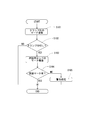
- FIG. 8 is a diagram showing a flowchart of the size determination process by executing the size determination program.
- the size determination process will be described.
- the clamp piece 62 attached to the clamp device 12 is confirmed (S101). That is, for any of the clamp pieces 62L, 62M, and 62S attached to the clamp unit 38, the recognition mark 621, 62, or 623 is imaged by the camera 6, and the imaged data is subjected to image processing by the control device 7. Thus, it is confirmed which size of the clamp piece 62 is attached.
- the clamp piece 62L is a long clamp piece 62L (S102). If the clamp piece 62L is not a clamp piece 62L but a medium or short clamp piece 62M or 62S. (S102: NO), this size determination process ends. This is because, in the present embodiment, the determination with respect to the interference with the mask receiver 58 is made only when the clamp piece 62L with the possibility of interference is attached. Therefore, in the case of the mask receiver 58, the clamp pieces 62M and 62S having a short size that cannot cause interference are transferred to the next driving process in the screen printer 1.
- the position of the pair of mask receivers 58 is confirmed (S103). That is, the camera 6 moves to the imaging position with respect to the confirmation rod 66 at the fixed position, and the imaging data of the camera 6 imaged there is sent to the control device 7 for image processing. Then, the position of the mask receiver 58 is confirmed depending on whether or not the recognition mark of the confirmation rod 66 has been imaged (S104). When the recognition mark can be confirmed (S104: YES), it can be seen that the pair of mask receivers 58 are largely separated as shown in FIG. At this time, since the interference between the mask receiver 58 and the clamp piece 62L does not occur, the size determination process ends.
- the interference between the mask receiver 58 and the clamp piece 62L is confirmed by the size determination process, so that the interference can be prevented in advance.
- the drive of the screen printing machine 1 is stopped by the warning process (S105)
- the operator can confirm the replacement mistake of the clamp piece 62 by the blinking display of the signal signal tower 8 or the like.
- the above-described effects can be achieved at low cost by performing the size determination process without significantly changing or adding the configuration to the conventional screen printing machine. Further, in the size determination process of the present embodiment, the position of the mask receiver 58 is confirmed only in the case of the clamp piece 62L with the possibility of interference, so that the processing time is shortened.
- the position of the mask receiver 58 is determined by imaging the confirmation rod 66 at a fixed position, it is possible to simplify the determination process required for interference determination.
- a mechanism for searching the mask receiver mark attached to the mask receiver 58 and the mask mark attached to the mask 20 with the camera 6 is used as another method for grasping the position of the mask receiver 58.
- the position of the mask receiver 58 may be accurately specified from the information.
- the positions of the mask receiver mark and the mask mark are not always constant.
- the confirmation rod 66 of the mask holder 2 is in a fixed position.
- the confirmation rod 66 can recognize the position of the mask receiver 58 in a short time.
- the camera 6 uses the mask reference mark (mask receiving mark). Since the position information of the encoder can be used when recognizing the mark (which may be the same or different from the position recognition mark), there is an advantage that the camera 6 can be moved to an appropriate mark reading position.
- the length of the clamp piece 62 can be determined from the imaging data of the recognition marks 621, 622, and 623, but it is determined by imaging the edge positions of the clamp pieces 62L, 62M, and 62S. May be.
- the clamp pieces 62M and 62S having a short size cannot be interfered with the mask receiver 58. Therefore, the confirmation rod 66 is discriminated by only one, but the clamp 62M also interferes. If there is, it is possible to attach the two confirmation rods 66 so that the position of the mask receiver 58 in the middle can also be confirmed.
Landscapes
- Engineering & Computer Science (AREA)
- Mechanical Engineering (AREA)
- Manufacturing & Machinery (AREA)
- Microelectronics & Electronic Packaging (AREA)
- Electric Connection Of Electric Components To Printed Circuits (AREA)
- Screen Printers (AREA)
Abstract
複数の貫通孔からなる印刷パターンが形成されたマスク(20)に対してクリームはんだを印刷パターンに押し込むスキージ装置(3)と、基板搬送方向における間隔調整が可能な一対のマスク受け部材(58)によってマスク(20)を保持するマスク保持装置(2)と、基板搬送方向と直行する方向に配置された一対の基板保持部(38)で基板(10)を保持し、当該基板をマスクに対して下方から位置決めする昇降機構(13)を備えた基板保持装置(5)と、移動可能な撮像装置(6)と、各装置の駆動を制御する制御装置(7)とを有し、基板保持部(38)は、基板サイズに応じて長さが異なるクランプ部材(62)がそれぞれベース部分(61)に着脱可能であり、制御装置(7)は、撮像装置(6)からの撮像情報に基づいてマスク受け部材(58)と基板保持部(38)との干渉判定を行うスクリーン印刷機(1)。
Description
本発明は、部材同士の干渉を防止するスクリーン印刷機に関する。
スクリーン印刷機は、機体内部に印刷パターン(印刷用の貫通孔)を有するマスクが保持され、その下には基板搬送装置によって基板が搬送され、その基板に対してクリームはんだによるスクリーン印刷が行われるよう構成されている。スクリーン印刷機には、基板搬送装置の他にも、搬送された基板を保持して印刷箇所に位置決めするための基板保持装置や、マスクを位置決めして保持するためのマスク保持装置、更にはマスクに対して上面からクリームはんだを塗り延ばすためのスキージ装置などが設けられている。
印刷対象となる基板には様々なサイズのものがあり、マスクに関しても基板に対応したサイズのものが用意されている。そのため、基板保持装置やマスク保持装置は、各々のサイズに変更するための段取り替えにおいて、部材の組換えや位置調整などが行われる。例えば、下記特許文献1には、マスク保持装置に関して、マスクの両端を保持するマスク支持台の間隔がサイズ変更に応じて調整できる構成が開示されている。また、基板保持装置に関しては、基板を幅方向から直接保持する一対のクランプ片を有し、そのクランプ片が、継片の脱着によって基板の大きさに従った長尺タイプや短尺タイプに長さを変更できる構成が開示されている。
前記従来例のスクリーン印刷機は、段取り替えにおいてクランプ片の長さを容易に変更することが可能である。しかし、作業者が行う段取り替えでは、マスクサイズを小さくしたためにマスク支持台の間隔が狭くなったにも関わらず、クランプ片を短尺タイプに切り替えるところ、誤って継片を装着した長尺タイプのままになってしまっていることが考えられる。この点は、マスク保持装置がマスク支持台の間隔を自動的に調整する機構を持ったスクリーン印刷機であればなおさら起こり得ることである。そして、マスク保持間隔が縮小したにも関わらず長尺のクランプ片を装着したままスクリーン印刷機を作動させてしまった場合には、マスク支持台とクランプ片との干渉が生じてしまい、それによって破損を引き起こすおそれがあり、あるいは各装置の調整が狂ってしまい再調整に時間や余分な手間を要することとなる。
そこで、本発明は、かかる課題を解決すべく、部材同士の干渉判定を行うスクリーン印刷機を提供することを目的とする。
本発明の一態様におけるスクリーン印刷機は、複数の貫通孔からなる印刷パターンが形成されたマスクに対してクリームはんだを前記印刷パターンに押し込むスキージ装置と、基板搬送方向における間隔調整が可能な一対のマスク受け部材によってマスクを保持するマスク保持装置と、基板搬送方向と直行する方向に配置された一対の基板保持部で基板を保持し、当該基板をマスクに対して下方から位置決めする昇降機構を備えた基板保持装置と、移動可能な撮像装置と、前記各装置の駆動を制御する制御装置とを有し、前記基板保持部は、基板サイズに応じて長さが異なるクランプ部材がそれぞれベース部分に着脱可能であり、前記制御装置は、前記撮像装置からの撮像情報に基づいて前記マスク受け部材と前記基板保持部との干渉判定を行うものである。
本発明によれば、基板保持部において長さが異なるクランプ部材のうち所定長さのものがベース部分に取り付けられた場合、撮像装置からの撮像情報に基づき、制御装置によって所定長さのクランプ部材を取り付けた基板保持部とマスク受け部材との干渉判定が行われるため、クランプ部材の取り付けに誤りがあったとしても、判定結果に基づいて干渉を防止した処理を行うことができる。
次に、本発明に係るスクリーン印刷機の一実施形態について、図面を参照しながら以下に説明する。図1は、本実施形態のスクリーン印刷機を示した斜視図であり、上面開閉カバーが開いた状態が示されている。また、図2は、スクリーン印刷機の内部を簡易的に示した側面図である。このスクリーン印刷機1は、基板に対してクリームはんだを印刷するものであり、例えば印刷状態を検査する検査機や基板に電子部品の装着を行う部品装着機などと共に回路基板生産ラインを構成する。
スクリーン印刷機1は、機内に設置されたマスクの下に基板が搬送され、マスク上面から印刷パターン(貫通孔)を通して下側の基板にクリームはんだが塗布されるものである。そこで、スクリーン印刷機1の機内上部側には、機体幅方向に配置された一対のマスクホルダ2があり、マスク枠に固定されたマスクが保持されるようになっている。そして、マスクホルダ2の更に上方側にはスキージ装置3が設置され、機体前後方向に移動可能な状態で取り付けられている。なお、本実施形態では、スクリーン印刷機1の機体前後方向をY軸方向、機体幅方向(基板10の搬送方向)をX軸方向、そして機体高さ方向をZ軸方向として説明する。
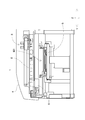
マスクホルダ2の下方側には、基板を搬送するとともに、所定の位置で基板を保持するための基板用テーブル5が設置されている。基板用テーブル5は、基板を機体幅方向に搬入及び搬出させる基板搬送装置、基板を機体前後方向にクランプするためのクランプ装置、そして基板をクランプ位置へと上下させるバックアップ装置などによって構成されている。図3は、そうした基板用テーブル5を中心に示したスクリーン印刷機の簡易的な内部構成図である。
スクリーン印刷機1は、全体が機体カバー4によって覆われている(図1参照)。機体カバー4の幅方向両側面には搬送口601が形成され、生産ラインの上流側から下流側へと移動する基板10に対し、搬送口601を通して基板搬送装置11による搬入および搬出が行われるようになっている。その基板搬送装置11は、基板用テーブル5に組み付けられたものであり、基板10の両サイドを支持する一対のコンベアベルト21によって構成されている。
そして、基板10を搬送するための基板搬送装置11および、搬送された基板10を保持するためのクランプ装置12が、昇降装置13に対して組み付けられている。昇降装置13は、垂直なガイドレール23に沿って摺動する昇降台24を備え、その昇降台24がボールネジ機構25を介して昇降用モータ26に連結されている。そして、昇降台24の上には支持台27を介して基板搬送装置11やクランプ装置12などが搭載されている。
支持台27の上には、機体前後方向(Y軸方向)に一対のマスクサポート31が設けられ、その間にクランプ装置12が配置されている。機体前後方向に位置する一対のマスクサポート31は、それぞれ機体幅方向(X軸方向)に門型の脚体311を備え、その上面にはマスク20が接触するマスク支持プレート312が固定されている。一方のマスクサポート31(図面右側)には、脚体311内部の固定ナットと1本のネジ軸32とが螺合したボールネジ機構が構成されている。従って、ネジ軸32を回転させる駆動モータの制御によって他方のマスクサポート31との距離の調整が可能になっている。
クランプ装置12は、支持台33に対し、基板10の搬送方向と直行する機体前後方向に一対のサイドフレーム35が配置され、一方のサイドフレーム35(図面右側)には内部の固定ナットにネジ軸37が螺合してボールネジ機構が構成され、ネジ軸37に対するクランプ用モータの回転によって他方のサイドフレーム35との距離が調整可能になっている。また、サイドフレーム35の上端部にはクランプ部38が形成され、互いの距離を調整することによって基板10が把持できるようになっている。そして、そのサイドフレーム35には基板搬送装置11が組み付けられており、そのコンベアベルト21によって搬送された基板10が一対のクランプ部38によって保持されることとなる。
また、一対のサイドフレーム35の間にはバックアップ装置14が設けられている。バックアップ装置14は、バックアップテーブル41に対して複数のバックアップピン42が取り付けられているが、そのバックアップピン42は、基板10に実装される電子部品を避けるようにして配置されている。そして、クランプ装置12の支持台33に対し、昇降用モータ43の回転出力を昇降運動に変換するボールネジ機構を介して支持されている。更に、支持台33に対して駆動モータ44が固定され、その回転出力を昇降運動に変換するボールネジ機構を介してバックアップテーブル41が支持されている。
次に、セットされたマスク20の上にはスキージ装置3が設けられている。スキージ装置3は、クリームはんだをローリングしながらマスク20の印刷パターンに押し込むことにより、マスク20の下に位置する基板10に塗布するものである。そのスキージ装置3は、スキージを備えた一対のスキージヘッド301,302がシリンダによって昇降可能な状態で走行台45に搭載されている。走行台45は、機体前後方向に架設されたガイドロッド46に対して摺動可能に組み付けられ、水平方向に直線移動が可能なものである。また、スクリーン印刷機1には、ガイドロッド46と平行なネジ軸47が回転自在な状態で架設され、駆動モータによって回転が与えられるようになっている。そして、走行台45内部の固定ナットとネジ軸47とによってボールネジ機構が構成されている。
さらに、マスクホルダ2と基板用テーブル5の間の高さには、基板10やマスク20に付された基板マークやマスクマークを撮像するためのカメラ6が設けられている。カメラ6は、Y軸スライダ48を介して機体前後方向のガイドレール51に取り付けられており、また、カメラ6を搭載したガイドレール51が、機体幅方向の2本のガイドレール52にX軸スライダ53を介して架設されている。従って、カメラ6は、Y軸スライダ48やX軸スライダ52によってXY平面上を移動できるよう構成されている。
そして、スクリーン印刷機1には、全体の駆動を制御する制御装置7が搭載され、各装置の駆動部に対して設定された駆動制御が行われるようになっている。制御装置7は、コンピュータおよび入出力部を含む制御部や複数の駆動回路などを備えている。そのコンピュータは、CPU、ROM、RAMおよびそれらを接続するバスを含み、入出力部には画像処理コンピュータが接続され、昇降用モータ26などが駆動回路を介して接続されている。
以上のように構成されたスクリーン印刷機1における基板10への印刷は、先ず、一対のサイドフレーム35の間にコンベアベルト21によって基板10が搬入される。そして、昇降用モータ44の駆動によりバックアップテーブル41が上昇し、バックアップピン42に突き上げられるようにして基板10がコンベアベルト11から持ち上げられる。また、ネジ軸37に回転が与えられることにより一方のサイドフレーム35が移動し、一対のサイドフレーム35のクランプ部38によって基板10が挟み込まれて保持される。
そして、昇降用モータ43の駆動により、基板10を保持した状態のクランプ装置12全体が上昇し、マスク支持プレート312の高さにクランプ部38と基板10の位置が合わせられ、上面の高さが揃えられた状態になる。その後、昇降用モータ26の駆動により昇降台24が上昇し、マスク支持プレート312、クランプ部38及び基板10の上面がマスク20の下面に軽く接触する印刷位置で停止する。一方、マスク20の上面側では、供給されたクリームはんだが、スキージ装置3によってマスク20上でローリングされて印刷パターンへと押し込まれる。これにより、印刷パターンの貫通孔を通ってマスク20の下に位置する基板10にクリームはんだが印刷される。
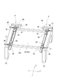
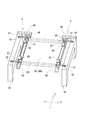
ところで、マスク20は、印刷パターンが形成された極めて薄い矩形形状の金属板であり、外縁部分が四角いマスク枠によって固定され、平面状態が保たれている。一対のマスクホルダ2は、基板10の搬送方向に所定の間隔で配置され、マスク枠の2辺を保持するようにしたものである。そして、こうしたマスクホルダ2は、機体幅方向に移動可能な位置調整機能を有し、マスク20のサイズに合わせた間隔調整が可能な構成を備えている。図4及び図5は、そのマスクホルダ2を示した斜視図であり、用意された複数のマスク20(例えば、大きい順にマスク20L,20M,20Sの3つ)のうち、図4は大きいサイズのマスク20Lを保持した状態を示し、図5は小さいサイズのマスク20Sを保持した状態を示している。
機体幅方向(X軸方向)に位置する一対のマスクホルダ2は、それぞれ門型の脚体55に対称的に組み付けられている。そのマスクホルダ2は、脚体55上面の2か所にガイドブロック56が固定され、それぞれ棒状のスライダ57が摺動可能に組み付けられ、さらに2本のスライダ57にマスク受け58が固定されている。従って、スクリーン印刷機1のマスクホルダ2は、作業者によってマスク20の大きさに応じて一対のマスク受け58の間隔が調整できるようになっている。例えば、スライダ57には目盛りが付けてあり、ガイドブロック56を基準にした位置合わせによりマスク20L,20M,20Sのそれぞれの大きさに合わせたマスク受け58の移動が可能になっている。
マスク受け58は、L字形の板状部材であり、マスク枠202が載る水平部分が向かい合うようにして配置されている。また、各々のマスク受け58には2個ずつのエアシリンダ59が取り付けられ、下方に伸張作動するピストンロッドの押え付けによりマスク枠202がマスク受け58に保持されるようになっている。図4に示す大きいマスク20Lから図5に示す小さいマスク20Sへの交換が行われる場合、つまりマスク20のサイズ縮小は基板10のサイズ変更に伴うため、クランプ装置12のクランプ部38についても変更が行われる。ここで、図6は、クランプ部38を示した斜視図である。
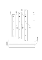
クランプ装置12のサイドフレーム35には、位置決め突起611が長手方向に形成されたベースプレート61が固定され、そのベースプレート61に対して用意された複数のクランプ片62がそれぞれ着脱可能な構成になっている。例えば、長尺なクランプ片62L、中尺なクランプ片62M、そして短尺なクランプ片62Sの3つのクランプ片62が用意されている。そうしたクランプ片62は、ベースプレート61に対してボルトによって定位置に固定される。
図7は、ベースプレート61に取り付けられたクランプ片62L,62M,62Sの位置関係を示した図である。サイズの縮小が行われる場合、マスク受け58は矢印で示す方向に移動することにより一点鎖線で示す位置への変更が行われる。クランプ装置12に取り付けられたクランプ片62の長さ方向は図1に示すように機体幅方向(X軸方向)である。そのため、機体幅方向に配置された一対のマスク受け58の距離が一定以上縮められると、マスク受け58が長尺なクランプ片62Lの端部に重なってしまい、前記課題でも述べたように、マスク受け58とクランプ片62Lとの干渉が生じてしまう。
具体的に干渉が生じる場合としては、一対のマスク受け58について図4から図5に示すように位置替えが行われたにも関わらず、クランプ片62Lがクランプ片62M又は62Sに交換されていない場合である。このような状態で基板10がマスク20に対して上昇すると、クランプ片62Lの端部がマスク受け58の下面に衝突しまう。この点、クランプ片62が正しく交換されていれば干渉することなく、基板10をマスク20へ接触させることができる。そこで、本実施形態では、作業者による交換ミスをなくしてマスク受け58とクランプ片62との干渉を防止するための構成が採られている。
先ず、クランプ部38を構成するクランプ片62L,62M,62Sに対して、図7に示すように、それぞれ形の異なる認識マーク621,622,623が付されている。本実施形態では、長いクランプ片62Lから順に四角、丸、菱形のマークが付されている。この認識マーク621,622,623はカメラ6によって撮像され、画像処理されるものである。なお、このマークはクランプ片の長さが識別できるものであればよいため、同じ形で大きさの異なるものなど、特に形状などが限定されるものではない。
一方、マスクホルダ2には、図4および図5に示すように、脚体55に対してX軸方向に平行なアーム65が固定され、そこに認識マークが下端面に付された確認用ロッド66が垂直に取り付けられている。確認用ロッド66の下端面の認識マークもカメラ6によって撮像され、画像処理されるものである。ただ、カメラ6の撮像データから確認用ロッド66の有無が認識できればよいため、認識マークは必ずしも必要ではない。そして、マスク受け58には遮蔽板67がX軸方向に平行な状態で固定されている。この遮蔽板67は、マスク受け58がクランプ片62Lと干渉する可能性のある位置まで移動した場合に、確認用ロッド66をカメラ6から隠すようにしたものである。
そして、制御装置7には、コンピュータのROMにサイズ判定部701が設けられ、サイズ判定プログラムが格納されている(図3参照)。図8は、そのサイズ判定プログラムの実行によるサイズ判定処理のフローチャートを示した図である。そこで次に、そのサイズ判定処理について説明する。サイズ判定処理では先ず、クランプ装置12に取り付けられているクランプ片62の確認が行われる(S101)。すなわち、クランプ部38に取り付けられているクランプ片62L,62M,62Sのいずれかについて、その認識マーク621,62又は623がカメラ6によって撮像され、その撮像データが制御装置7によって画像処理されることにより、どのサイズのクランプ片62が取り付けられているかについて確認が行われる。
次に、確認されたクランプ片62が、長尺のクランプ片62Lであるか否かについて判定が行なわれ(S102)、クランプ片62Lではなく中尺や短尺のクランプ片62M又は62Sの場合には(S102:NO)、このサイズ判定処理が終了する。本実施形態では、干渉の可能性のあるクランプ片62Lが取り付けられている場合にのみマスク受け58との干渉について判定が行われるようにしているからである。よって、干渉が生じ得ない短いサイズのクランプ片62M,62Sはマスク受け58の場合には、スクリーン印刷機1における次の駆動処理へと移行することとなる。
クランプ片62Lが取り付けられている場合には(S102:YES)、一対のマスク受け58について位置確認が行われる(S103)。すなわち、定位置にある確認用ロッド66に対する撮像位置へカメラ6が移動し、そこで撮像されたカメラ6の撮像データが制御装置7へと送られて画像処理される。そして、確認用ロッド66の認識マークが撮像されているか否かによってマスク受け58の位置が確認される(S104)。認識マークが確認できた場合は(S104:YES)、図4に示すように一対のマスク受け58が大きく距離を離した状態であることが分かる。このとき、マスク受け58とクランプ片62Lとの干渉は生じないためサイズ判定処理が終了する。
一方、図5に示すように、一対のマスク受け58の距離が近い状態にある場合は、遮蔽板67が確認用ロッド66とカメラ6との間に位置することで認識マークが撮像できない。このように撮像データから認識マークが確認できない場合は(S104:NO)、クランプ装置12を上昇させることなく警告処理が行われる(S105)。そして、サイズ判定処理が終了する。警告処理では、スクリーン印刷機1の駆動停止が行われ、シグナルタワー8を点滅表示させ、或いはブザーや音声などにより作業者への報知が行われる。そこで、取り付けミスに気が付いた作業者により、クランプ片62Lがベースプレート61から取り外され、クランプ片62M又は62Sが付け替えられる。
よって、本実施形態によれば、クランプ片62の取り付けに誤りがあったとしても、サイズ判定処理によってマスク受け58とクランプ片62Lとの干渉を確認するため、予めその干渉を防止することができる。特に、警告処理(S105)によってスクリーン印刷機1の駆動が停止するため、クランプ部38が上昇することなく、マスク受け58の下面にクランプ片62Lの端部が衝突することを防止することができる。また、シグナルシグナルタワー8の点滅表示などにより、クランプ片62の交換ミスを作業者に確認させることができる。
そして、本実施形態では、従来のスクリーン印刷機に対して構成を大幅に変更や追加することなく、サイズ判定処理を行うことで安価に上記効果を達成することができる。また、本実施形態のサイズ判定処理では、干渉の可能性のあるクランプ片62Lの場合にのみマスク受け58の位置確認が行われるようにしたため、処理時間の短縮が図られている。
更に、本実施形態では、定位置の確認用ロッド66を撮像することによってマスク受け58の位置を判定するようにしたため、干渉判断に必要な判定処理を単純化することができる。この点、マスク受け58の位置を把握する他の方法として、マスク受け58に付したマスク受けマークや、マスク20に付されたマスクマークをカメラ6でサーチする機構とし、カメラ軸モータのエンコーダ位置情報からマスク受け58の位置を正確に特定するようにしてもよい。ただし、マスク受け58やマスク20の設置には作業者が介在するため、マスク受けマークやマスクマークの位置が一定とは限らない。この点、マスクホルダ2の確認用ロッド66は定位置にある。
よって、確認用ロッド66であればマスク受け58の位置の認識が短時間でできる。その一方で、マスクマークをカメラ6でサーチする機構では、マスクマークの認識に時間を要するおそれがあるが、基板10とマスク20の位置あわせをするためにカメラ6がマスクの基準マーク(マスク受け位置認識マークと同じでも異なるマークでもよい)を認識する際、エンコーダの位置情報を利用できるので、カメラ6を適切なマーク読み取り位置へ移動させることができる利点がある。
以上、本発明の一実施形態について説明したが、本発明はこれらに限定されるものではなく、その趣旨を逸脱しない範囲で様々な変更が可能である。
例えば、前記実施形態では認識マーク621,622,623の撮像データからクランプ片62の長さを判別できるようにしたが、クランプ片62L,62M,62Sのエッジ位置を撮像することで判別するようにしてもよい。
また、前記実施形態では、短いサイズのクランプ片62M,62Sではマスク受け58との干渉が生じ得ないため、確認用ロッド66を1本だけで判別するようにしたが、クランプ62Mでも干渉する場合があるとすれば、2本の確認用ロッド66を取り付けて中間でのマスク受け58の位置も確認できるようにしてもよい。
例えば、前記実施形態では認識マーク621,622,623の撮像データからクランプ片62の長さを判別できるようにしたが、クランプ片62L,62M,62Sのエッジ位置を撮像することで判別するようにしてもよい。
また、前記実施形態では、短いサイズのクランプ片62M,62Sではマスク受け58との干渉が生じ得ないため、確認用ロッド66を1本だけで判別するようにしたが、クランプ62Mでも干渉する場合があるとすれば、2本の確認用ロッド66を取り付けて中間でのマスク受け58の位置も確認できるようにしてもよい。
1…スクリーン印刷機 2…マスクホルダ 3…スキージ装置 5…基板用テーブル 6…カメラ 7…制御装置 10…基板 12…クランプ装置 13…昇降装置 14…バックアップ装置 20(20L,20M,20S)…マスク 38…クランプ部 58…マスク受け 61…ベースプレート 62(62L,62M,62S)…クランプ片 67…遮蔽板 66…確認用ロッド 621,622,623…認識マーク
Claims (5)
- 複数の貫通孔からなる印刷パターンが形成されたマスクに対してクリームはんだを前記印刷パターンに押し込むスキージ装置と、
基板搬送方向における間隔調整が可能な一対のマスク受け部材によってマスクを保持するマスク保持装置と、
基板搬送方向と直行する方向に配置された一対の基板保持部で基板を保持し、当該基板をマスクに対して下方から位置決めする昇降機構を備えた基板保持装置と、
移動可能な撮像装置と、
前記各装置の駆動を制御する制御装置とを有し、
前記基板保持部は、基板サイズに応じて長さが異なるクランプ部材がそれぞれベース部分に着脱可能であり、
前記制御装置は、前記撮像装置からの撮像情報に基づいて前記マスク受け部材と前記基板保持部との干渉判定を行うものであることを特徴とするスクリーン印刷機。 - 前記制御装置は、撮像情報から該当する前記クランプ部材を特定し、特定したクランプ部材が判定対象として設定された長尺なクランプ部材である場合に、前記マスク受け部材と前記基板保持部との干渉判定を行うものであることを特徴とする請求項1に記載のスクリーン印刷機。
- 前記クランプ部材には、長さに応じて異なる形状のサイズ認識マーク、または長さに応じて同一形状で大きさが異なるサイズ認識マークが付され、
前記制御装置は、前記サイズ認識マークの撮像情報から該当する前記クランプ部材を特定し、前記マスク受け部材と前記基板保持部との干渉判定を行うものであることを特徴とする請求項1又は請求項2に記載のスクリーン印刷機。 - 前記撮像装置は、マスクおよび基板に付されたマスクマークや基板マークを撮像するものであり、前記制御装置は、前記撮像装置によって撮像された前記マスクマークの位置から前記マスク受け部材の位置を確認することにより、前記マスク受け部材と前記基板保持部との干渉判定を行うものであることを特徴とする請求項1乃至請求項3のいずれかに記載のスクリーン印刷機。
- 前記マスク受け部材に対して取り付けられた一又は移動方向に並んだ二以上のマスク受け用認識マークと、前記マスク受け部材の移動位置によって前記マスク受け用認識マークを前記撮像装置から遮蔽する遮蔽部材とを有し、
前記制御装置は、前記マスク受け用認識マークの撮像情報の有無によって前記マスク受け部材の位置を確認し、前記マスク受け部材と前記基板保持部との干渉判定を行うものであることを特徴とする請求項1乃至請求項3のいずれかに記載のスクリーン印刷機。
Priority Applications (2)
| Application Number | Priority Date | Filing Date | Title |
|---|---|---|---|
| PCT/JP2016/074965 WO2018037552A1 (ja) | 2016-08-26 | 2016-08-26 | スクリーン印刷機 |
| JP2018536021A JP6810747B2 (ja) | 2016-08-26 | 2016-08-26 | スクリーン印刷機 |
Applications Claiming Priority (1)
| Application Number | Priority Date | Filing Date | Title |
|---|---|---|---|
| PCT/JP2016/074965 WO2018037552A1 (ja) | 2016-08-26 | 2016-08-26 | スクリーン印刷機 |
Publications (1)
| Publication Number | Publication Date |
|---|---|
| WO2018037552A1 true WO2018037552A1 (ja) | 2018-03-01 |
Family
ID=61245592
Family Applications (1)
| Application Number | Title | Priority Date | Filing Date |
|---|---|---|---|
| PCT/JP2016/074965 Ceased WO2018037552A1 (ja) | 2016-08-26 | 2016-08-26 | スクリーン印刷機 |
Country Status (2)
| Country | Link |
|---|---|
| JP (1) | JP6810747B2 (ja) |
| WO (1) | WO2018037552A1 (ja) |
Citations (3)
| Publication number | Priority date | Publication date | Assignee | Title |
|---|---|---|---|---|
| JPS62123793A (ja) * | 1985-11-22 | 1987-06-05 | ソニー株式会社 | 回路基板の位置決め装置 |
| JP2006007625A (ja) * | 2004-06-28 | 2006-01-12 | Matsushita Electric Ind Co Ltd | スクリーン印刷装置およびスクリーン印刷方法 |
| JP2007190714A (ja) * | 2006-01-17 | 2007-08-02 | Yamaha Motor Co Ltd | スクリーン印刷装置 |
-
2016
- 2016-08-26 WO PCT/JP2016/074965 patent/WO2018037552A1/ja not_active Ceased
- 2016-08-26 JP JP2018536021A patent/JP6810747B2/ja active Active
Patent Citations (3)
| Publication number | Priority date | Publication date | Assignee | Title |
|---|---|---|---|---|
| JPS62123793A (ja) * | 1985-11-22 | 1987-06-05 | ソニー株式会社 | 回路基板の位置決め装置 |
| JP2006007625A (ja) * | 2004-06-28 | 2006-01-12 | Matsushita Electric Ind Co Ltd | スクリーン印刷装置およびスクリーン印刷方法 |
| JP2007190714A (ja) * | 2006-01-17 | 2007-08-02 | Yamaha Motor Co Ltd | スクリーン印刷装置 |
Also Published As
| Publication number | Publication date |
|---|---|
| JPWO2018037552A1 (ja) | 2019-06-20 |
| JP6810747B2 (ja) | 2021-01-06 |
Similar Documents
| Publication | Publication Date | Title |
|---|---|---|
| CN107709014B (zh) | 印刷装置及对基板作业装置 | |
| US20110297020A1 (en) | Screen printer and screen printing method | |
| JP6142290B2 (ja) | スクリーン印刷機、部品実装ライン及びスクリーン印刷方法 | |
| KR102366109B1 (ko) | 스텐실 프린터용 리프트 툴 어셈블리 | |
| CN103515274B (zh) | 焊球印刷搭载装置 | |
| JP5536470B2 (ja) | スクリーン印刷装置 | |
| JP7086862B2 (ja) | スクリーン印刷機 | |
| EP2897449B1 (en) | Work system for substrate and workbench-quantity-determining program | |
| JP4852456B2 (ja) | 実装ライン及び実装方法 | |
| JP5906398B2 (ja) | スクリーン印刷装置及びスクリーン印刷装置におけるマスク位置決め方法 | |
| JPWO2017145280A1 (ja) | スクリーン印刷機 | |
| JP2007335524A (ja) | 実装ライン | |
| JP7002181B2 (ja) | スクリーン印刷機 | |
| JP6137813B2 (ja) | 印刷機 | |
| JP6810747B2 (ja) | スクリーン印刷機 | |
| JP6760823B2 (ja) | スクリーン印刷機 | |
| JP5536438B2 (ja) | スクリーン印刷装置 | |
| JP5370229B2 (ja) | 電子部品実装用装置及び電子部品実装用装置による作業方法 | |
| CN111093996A (zh) | 丝网印刷机 | |
| JP2012248591A (ja) | 部品実装システム及び部品実装方法 | |
| CN103619593A (zh) | 网版印刷装置 | |
| JP2010238820A (ja) | 支持ピン移載装置 | |
| JP6207903B2 (ja) | はんだ印刷装置 | |
| JP2012248590A (ja) | 部品実装システム及び部品実装方法 | |
| JP2023168369A (ja) | 対基板作業装置 |
Legal Events
| Date | Code | Title | Description |
|---|---|---|---|
| ENP | Entry into the national phase |
Ref document number: 2018536021 Country of ref document: JP Kind code of ref document: A |
|
| 121 | Ep: the epo has been informed by wipo that ep was designated in this application |
Ref document number: 16914226 Country of ref document: EP Kind code of ref document: A1 |
|
| NENP | Non-entry into the national phase |
Ref country code: DE |
|
| 122 | Ep: pct application non-entry in european phase |
Ref document number: 16914226 Country of ref document: EP Kind code of ref document: A1 |